gcl gcx operator manual warranty - amazon web services
TRANSCRIPT

™ 08-12
This Installation Manual provides the information required to install, troubleshoot andmaintain a GCL-GCX™ Counter Door Operator.
NOT FOR RESIDENTIAL USE
PROPER APPLICATION
Door Type Operator Type Max Door Weight/HP
Rolling Steel Counter Door 1/2HP = 500 lbs.Counter Door
112070.501539
COMMERCIAL LINE
COUNTER DOOR OPERATOR
GCL-GCX

Section 1 How to use this manual . . . . . . . . . . . . . . . . . . . . . . . . . . . . . . 1.1
Section 2 Safety Information & Instructions . . . . . . . . . . . . . . . . . . . . 2.1
Section 3 Critical Installation Information . . . . . . . . . . . . . . . . . . .3.1-3.3Section 4 Installation . . . . . . . . . . . . . . . . . . . . . . . . . . . . . . . . . . . . . . 4.1-4.3
Mounting. . . . . . . . . . . . . . . . . . . . . . . . . . . . . . . . . . . . . . . . . .4.1-4.2
Manual Release . . . . . . . . . . . . . . . . . . . . . . . . . . . . . . . . . . . . . . . 4.3
Optional Timer-Close or Aux. Output Modules . . . . . . . . . 4.4
Section 5 Wiring . . . . . . . . . . . . . . . . . . . . . . . . . . . . . . . . . . . . . . . . . . . 5.1-5.8
Line Voltage Wiring . . . . . . . . . . . . . . . . . . . . . . . . . . . . . . . . . . . .5.1
Low Voltage Control Wiring . . . . . . . . . . . . . . . . . . . . . . . . . . . 5.2
External Wire Diagram . . . . . . . . . . . . . . . . . . . . . . . . . . . . . . . . 5.3
Wall Control . . . . . . . . . . . . . . . . . . . . . . . . . . . . . . . . . . . . . . . . . . 5.4
Montored/Non-monitored Photocells . . . . . . . . . . . . . . . . . 5.5
Locking Bottom Bar / Interlock Switch. . . . . . . . . . . . . . . . . . 5.7 Montored/Non-monitored Sensing Edge . . . . . . . . . . . . . . 5.6
External Radio/Safety Instructions . . . . . . . . . . . . . . . . . . . . . 5.8
Section 6 Operator Setup Procedures . . . . . . . . . . . . . . . . . . . . . . .6.1-6.7
Setting Close Direction. . . . . . . . . . . . . . . . . . . . . . . . . . . . . . . . 6.2
6.3
Setting
Travel
Limits . . . . . . . . . . . . . . . . . . . . . . . . . . . . . . . . . .
6.4
Control Panel . . . . . . . . . . . . . . . . . . . . . . . . . . . . . . . . . . . . . . . . .
Setting
Limit
Overrun . . . . . . . . . . . . . . . . . . . . . . . . . . . . . . . . .
6.5
Setting
Open
&
Close
Modes . . . . . . . . . . . . . . . . . . . . . . . . . .
6.6
6.7
Setting Mid-Stop Limit . . . . . . . . . . . . . . . . . . . . . . . . . . . . . . . .
Resetting the MRT, Monitored Reversing Devices . . . . .
Section 7 Special Operational Features. . . . . . . . . . . . . . . . . . . . . 7.1-7.4 Operator Cycle Count. . . . . . . . . . . . . . . . . . . . . . . . . . . . . . . . . 7.1 GDO & Display Firmware . . . . . . . . . . . . . . . . . . . . . . . . . . . . . .7.1 Operator Type . . . . . . . . . . . . . . . . . . . . . . . . . . . . . . . . . . . . . . . .7.2 Optional Hand Crank. . . . . . . . . . . . . . . . . . . . . . . . . . . . . . 7.3-7.4
Section 8 Troubleshooting . . . . . . . . . . . . . . . . . . . . . . . . . . . . . . . . 8.1-8.5 Display Operation. . . . . . . . . . . . . . . . . . . . . . . . . . . . . . . . . . . . .8.1 Error Codes . . . . . . . . . . . . . . . . . . . . . . . . . . . . . . . . . . . . . . . 8.1-8.2 Run Codes . . . . . . . . . . . . . . . . . . . . . . . . . . . . . . . . . . . . . . . . 8.2-8.3 LED Indicators . . . . . . . . . . . . . . . . . . . . . . . . . . . . . . . . . . . . . . . .8.4 Safe-T-Beam® Self-Diagnostic Troubleshooting Chart . .8.5
Section 9 Service & Maintenance . . . . . . . . . . . . . . . . . . . . . . . . . . . . . .9.1 Periodic Maintenance Schedule . . . . . . . . . . . . . . . . . . . . . . . . . . .9.1
Section 10 Appendixes . . . . . . . . . . . . . . . . . . . . . . . . . . . . . . . . . . 10.1-10.7 Appendix A . . . . . . . . . . . . . . . . . . . . . . . . . . . . . . . . . . . . . . . 10.1-10.2 Operator Parts Breakdown (Exploded View) . . . . . . 10.1 Operator Parts Breakdown (Parts List) . . . . . . . . . . . . 10.2 Base Electric Box Parts Breakdown . . . . . . . . . . . . . . . 10.3 Appendix B. . . . . . . . . . . . . . . . . . . . . . . . . . . . . . . . . . . . . . . . . . . . . 10.4 Screw Terminal Assignments. . . . . . . . . . . . . . . . . . . . . 10.4 Appendix C. . . . . . . . . . . . . . . . . . . . . . . . . . . . . . . . . . . . . . . . 10.5-10.7 Run Codes. . . . . . . . . . . . . . . . . . . . . . . . . . . . . . . . . . . . . . . 10.5 Error Codes. . . . . . . . . . . . . . . . . . . . . . . . . . . . . . . . . 10.6-10.7
Section 11 Warranty . . . . . . . . . . . . . . . . . . . . . . . . . . . . . . . . . . . . . . . . . 11.1
Table of Contents
6.1
TOCwww.geniecompany.com 08-12Counter Door OperatorGCL-GCX

Section 1: How to use this manualThe 11 sections of this Installation Manual provide the information required to install, troubleshoot and maintain an GCX commercial/industrial door operator.
Section 2 Provides important defining information related to safety terminology used throughout this manual, as well as safety related instructions which must be followed at all times while doing any steps/tasks/instructions detailed in this manual.
Section 3 Details pre-installation concerns/issues/decisions that are recommended to be considered and/or resolved prior to beginning any commercial door operator installation.
Sections 4-6 Provide step by step installation and set-up instructions for the GCX commercial door operator. Each section is written such that it must be followed in a step by step order to complete a successful installation.
Sections 7-8 Detail important features and troubleshooting information for typical installation and normal operations that may occur.
Sections 9-11 Provide related information on service and maintenance items, operator drawings for use in troubleshooting and service activities, along with important warranty and returned goods policy information.
Failure to correctly perform all steps in sections 4-6 can result in serious injury or death. WARNING
1.1www.geniecompany.com 08-12Counter Door OperatorGCL-GCX

Section 2: Safety Information & Instructions
WARNINGOverhead Doors are large, heavy objects that move with the help of springs under high tension and electric motors. Since moving
gnidaer uoy no dneped srehto fo ytefas eht dna ytefas ruoy ,seirujni esuac nac srotom cirtcele dna ,noisnet rednu sgnirps ,stcejbo ecivres tseraen ruoy llac ,detneserp noitamrofni eht dnatsrednu ton od ro snoitseuq yna evah uoy fI .launam siht ni noitamrofni eht
representative. For the number of your local Genie® Dealer, call 800-OK-GENIE, and for Genie® Factory Technical call 800-843-4084.
Advice,
In this Manual, the words Danger, Warning, and Caution are used to stress important safety information. The word: DANGER indicates an imminently hazardous situation which, if not avoided, will result in death or serious injury. WARNING indicates a potentially hazardous situation which, if not avoided, could result in death or serious injury. CAUTION indicates a potentially hazardous situation which, if not avoided, may result in injury or property damage.
The word NOTE is used to indicate important steps to be followed or important considerations.
IMPORTANTREAD PRIOR TO ANY DOOR OPERATION
POTENTIAL HAZARD EFFECT PREVENTION
Do Not operate unless the doorway is in sight and free of obstructions. Keep people clear of opening while door is moving.Do Not allow children to play with the door operator.Do Not change operator control to momentary contact unless an external reversing means is installed.Do Not operate a door that jams or one that has a broken spring
Could result inSerious Injury
or Death
Turn off electrical power before removing operator cover. When replacing the cover, make sure wires are not pinched or near moving parts.Operator must be electrically grounded.
ELECTRICAL SHOCKDo Not try to remove, repair or adjust springs or anything to which door spring parts are fastened, such as, wood block, steel bracket, cable or any other structure or like item.Repairs and adjustments must be made by a trained service
.snoitcurtsni dna sloot reporp gnisu evitatneserperHIGH SPRING TENSION
WARNING
MOVING DOOR
1. Read manual and warnings carefully.2. Keep the door in good working condition. Periodically lubricate all moving parts of door.3. If door has a sensing edge, check operations monthly. Make any necessary repairs to keep it functional.4. AT LEAST twice a year, manually operate door by disconnecting it from the operator. The Door should open and close freely. If it does not, the door must be taken out of service and a trained service representative must correct the condition causing the malfunction.5. The Operator Motor is protected against overheating by an internal thermal protector. If the operator ceases to function because motor protector has tripped, a trained service technician may need to correct the condition which caused the overheating. When motor has cooled, thermal protector will automatically reset and normal operation can be resumed.6. In case of power failure, the door can be operated manually by pulling the release cable to disconnect the operator drive system. 7. Keep instructions in a prominent location near the pushbutton.
Could result inSerious Injury
or Death
WARNING
Could result inSerious Injury
or Death
WARNING
2.1www.geniecompany.com 08-12Counter Door OperatorGCL-GCX

3.1
Job Site Issues to Consider/ConcernsThe following list of items should be considered prior to selecting an operator for a given job site.1-Available power supply. 2-Type of door. 3-Potential operator mounting obstructions. Items to consider include, but are not limited to: side room, room above door shaft, room below door shaft, available mounting
surface integrity, power supply location, and convenient chain hoist and release cable positioning. 4-Size of door for appropriate operator torque and door travel speed selection. 5-Operator mounting environment. Items to consider include operator location, dampness of location, dustiness of the location and corrosiveness of the location. 6-Door activation needs/requirements. Examples include 3 button control stations, 1 button control stations, radio controls, pull cords, loop detectors, photoelectric controls,
key switches, etc. See “Entrapment Protection” section below. 7-Interlock switches are required under certain conditions for doors with pass doors and door locks. See Section
5.5 below.
8-Accessory equipment. Examples include reversing edges and/or photocell beams, which are required for doors set to operate as momentary contact, auxiliary control relays, warning lights, etc. See “Entrapment Protection” section below.
WARNING: DO NOT apply line voltage until instructed to do so.
CAUTION: Check working condition of door before installing the operator. Door must be free from sticking and binding. If equipped, deactivate any door locking device(s). Door repairs and adjustments, including cables and spring assemblies MUST be made by a trained service representative using proper tools and instructions.
Section 3: Critical Installation Information
ENTRAPMENT PROTECTIONThe installation of a fail safe external reversing device (such as a monitored reversing edge or photocell system, etc.) is required on all momentary contact electronicallyoperated commercial doors. If such a reversing device is not installed, the operator will revert to a constant contact control switch for operation (Closing only). The Reversing Devices currently UL Approved with this model are:
MillerEdge ME, MT and CPT series monitored edge sensors used in combination with Timer-Close Module P/N OPABTCX.S, and/or OPAKMEIGX.S INTERFACE MODULE.
2) Residential Safe-T-Beam® Monitored Photocells from The Genie® Company, model OSTB-BX (P/N 38176R).3) Series II Commercial Safe-T-Beam®, Monitored Photocells P/N OPAKPE.S. 4) Series II Commercial Safe-T-Beam®, Monitored Photocells P/N OPAKPEN4GX.S.
1)
www.geniecompany.com 08-12Counter Door OperatorGCL-GCX

GCL-GCX
ENTRAPMENT PROTECTIONThe GCX can be used with the following UL Listed entrapment devices in compliance with UL325 requirements active starting August 29, 2010.UNTIL ONE OF THESE MONITORED EXTERNAL ENTRAPMENT DEVICES IS INSTALLED, THE OPERATOR WILL NOT ALLOW MOMENTARY CONTACT OPERATION IN THE CLOSE DIRECTION.
Model HPFIRESTAR 3” SLAT
FIRESTAR 3” SLAT INSULATED SHEET DOOR
16GA. 18GA. 20GA. 22GA. 24GA. 26GA. 18GA. 20GA. 22GA. ALUM. STL/SST 20GA. 22GA.142 108 82 94 N/A
STEEL, NON-INSULATED STEEL, INSULATEDULL is ted
FIRESTAR 2” SLATGRILLESCOUNTER DOOR
ALUM. STL/SST
126 126
Rolling Steel Door Chart (sq. ft.)
Note: Total door weight and not square footage is the critical factor in selecting the proper operator. These Sq.Ft. measurements are based on square doors, e.g. 16' x 16'.
Unbalanced Fire Shutters have a maximum square footage of 52 for 22GA. steel and 42 for 20GA. steel.
GCL-GCX 1/2 YES N/A N/A 144 144 144 144 N/A N/A N/A 16GA. 18GA. 20GA. 22GA.
N/A N/A N/A
20GA. 22GA. 26GA.
N/A N/A N/A
3.2
APPROVED
DEVICES
ALLOWABLE DOOR WIDTH
ANY
WIDTH
30 FEET
30 FEET
30 FEET
Miller Edge ME, MT & CPT series monitored edge sensors used in combination with either the Genie® Timer-Close Module or Direct connect through STB inputs using the OPAKMEIGX.S Interface Module.
Commercial Photoeye Kit—P/N OPAKPE.S.
Safe-T-Beam® from Genie®—P/N 38176R.
Monitored Photocells—P/N OPAKPEN4GX.S.
www.geniecompany.com 08-12Counter Door Operator

3.3www.geniecompany.com 08-12Counter Door OperatorGCL-GCX
IMPORTANTINSTALLATION INSTRUCTIONS
WARNING To reduce the risk of severe injury or death:
1) READ AND FOLLOW ALL INSTALLATION INSTRUCTIONS.2) Install only on a properly operating and balanced door. A door that is operating improperly could cause severe injury. Have qualified service personnel make repairs to cables, spring assemblies and other hardware before installing the operator.3) Remove all pull ropes and remove, or make inoperative, all locks (unless mechanically and/or electronically interlocked to the power unit) that are connected to the door before installing the operator.4) Install the door operator at least 8 feet above the floor if the operator has exposed moving parts.5) Do not connect the door operator to the power source until instructed to do so.6) Locate the control station: (a) within sight of the door, (b) a minimum of 5 feet above the floor so that small children cannot reach it, and (c) away from all moving parts of the door.7) Install the Entrapment Warning Placard next to the control station and in a prominent location.8) For products having a manual release, instruct the end user on the operation of the manual release.

4.1
Unless otherwise stated, these instructions will show right side mount installations. Left side mount is opposite. 1) Insert four(4) 3/8"-16 x 1" carriage bolts into headplate. FIG. 1. • Threads to outside of plate. • Retain by pushing 4 speed nuts onto bolts. 2) Complete installation of door as instructed in door installation manual up to "mounting of hood." 3) Make certain both headplates are at 90° to wall. • If not at 90°, use temporary external brace to hold in place. 4) Install hood and secure with hood mounting screws. • When hood is secure, remove temporary brace if used (in step3). • Leave door in FULL OPEN position. 5) Place 3/8" flat washers and 3/8"-16 keps nuts on 3/8" carriage bolts closest to wall. FIG. 2. • Leave nuts flush with ends of bolts.
.rotarepo XCG morf draug niahc evomeR )6
Section 4: InstallationMounting
Figure 1 Figure 2
CARRIAGEBOLT WALL
FLAT WASHERS & KEPS NUTS
SPEEDNUT
nuts flush with end of bolts
www.geniecompany.com 08-12Counter Door OperatorGCL-GCX

GCL-GCXGCL-GCX
Mounting (continued)
7) Slide open ended slots of frame under flat washers installed in step 5. FIG. 3. • Locate other frame slots over remaining two(2) carriage bolts and bring frame against headplate. • Put 3/8" washers and keps nuts on remaining bolts. • DO NOT fully tighten nuts. • Slide operator toward wall as far as slots allow. FIG. 4. 8) Place driven sprocket and key on door shaft and align with output sprocket on operator. FIG. 4A. • Secure sprocket and key in place with set screws. 9) Wrap #25 roller chain around both sprockets and join with connecting link. FIG. 5 & 6. • Chain length is correct for 9-1/2" headplate. • For 11-1/2" headplate, add short #25 chain (provided) to long chain using extra connecting link. • Slide operator away from hood until drive chain is tensioned but not tight. FIG. 7. • Tighten mounting nuts.
Figure 3
Figure 6
Figure 5
Figure 7
4.2
TOWARD WALL AS FAR AS SLOTS WILL ALLOW
Figure 4
Figure 4A
90°
www.geniecompany.com 08-12Counter Door Operator

GCL-GCXGCL-GCX
Manual Release
NOTE: In case of power failure, door can be operated manually. The operator can be disconnected from door by pulling red pull rope attached to Drop Release Lever to allow opening door. FIG. 8.
FIG. 8.
• When door is in manual operation, limit switch setting is not affected. • Releasing pull rope will re-engage operator.
Figure 8
Figure
DROP RELEASE LEVER
4.3
1) Install Release Cord.
2) Locate and install the wall control.
3) Locate and install Warning Placard. FIG. 9.
Warning Placard MUST BE ATTACHED
to push button.
111735 00 1
(install release cord here)
9
ADJACENT
4) Remove four (4) self-tapping screws from front panel of the enclosure and remove front panel to expose control circuits and allow for installation of
any optional accessory board. to
www.geniecompany.com 08-12Counter Door Operator

GCL-GCX
These instructions apply to either board. Although they perform different functions, they mount in the same way.
2) Orient the module so mounting bracket tabs are to the left and wire terminals are facing up. 3) Make desired wiring connections, in accordance with instruction manual accompanying the module. 4) Insert module into the area indicated and slide front mounting tab into slot on side panel of the enclosure. FIG. 10 & 11. 5) Adjust module so that it is level with GCX enclosure. • There is a mounting hole on side panel of enclosure which will line up with hole in module mounting bracket. • Attach module by inserting self-tapping screw (provided in kit) through module bracket and into hole in side panel. Do not overtighten. 6) Replace front panel.
Optional Timer-Close Module or Auxiliary Output ModuleFigure 10
Figure 11
MOUNTINGBRACKETTAB
Self tapping screw
4.4www.geniecompany.com 08-12Counter Door Operator

GCL-GCX
WARNING • DO NOT apply power to operator until instructed to do so. • The Genie® Company recommends that line voltage wiring be performed by a qualified electrician. • Be sure that electrical power has been disconnected from the input power wires being connected to the operator prior to handling these wires. An appropriate lock-out /tag-out procedure is recommended. • Line voltage wiring must meet all local building codes. • Make sure operator voltage, phase and frequency nameplate ratings are identical to the job site line voltage ratings. • Input power wiring must be properly sized for the operators amperage rating located on the nameplate. • To reduce the risk of electric shock, make sure the chassis of this unit is properly grounded.
1) Remove LINE VOLTAGE INPUT PLUG and install proper fittings and 1/2”conduit. 2) Route proper LINE VOLTAGE wires into operator. 3) Locate LINE INPUT terminals on circuit board. Using correct connectors, attach wires to LINE INPUTS, and GROUND terminal. • Keep low voltage and line voltage wires separate. • Route all line voltage wires as shown. • Plug all unused conduit holes.
S S B S Y
S YS B S B
STBENAB+ 4VACEXTIN LKHOISTIN LK
CALRUN
SETCLR
SCROLL
SCROLL
Section 5: Wiring
Figure 1
Line Voltage Wiring Fig. 1
5.1www.geniecompany.com 08-12Counter Door Operator

GCL-GCX
1) Connect all LOW VOLTAGE control circuit wires to this side
of unit using 1/2” conduit or flexible convoluted
tubing.
• Keep low voltage and line voltage wires separate. • Route all low voltage control wiring as shown. This
includes
all control circuit wires such as wall controls, timers and single
button
input
devices
as
well
as radio control and safety
circuit wiring.
• Plug all unused conduit holes.
Low Voltage Control Wiring Fig. 2
S S B S Y
SS B S B
STBENAB+ 24VACEXTNTLK
HO STNTLK
CALRUN
SETCLR
SCROLL
SCROLL
Figure 2
5.2www.geniecompany.com 08-12Counter Door Operator

5.3
External Wire DiagramSee Appendix B for detailed description of terminals.
1-BTNSTATION
KEYSWITCHSTATION
CARD READER
O/C PULLSWITCH
N/O
N/O
N/O
N/O
REMOVE JUMPER WHEN INSTALLING EXTERNAL INTERLOCK
MULT PLE 3 BUTTONSTAT ON NSTALLAT ONS
REQU RE THE STOP BUTTON TO BE W REDN SER ES
See Fig 5 pg 5 4
*
EXTINTLK
EXTINTLK
N-OREVERSE
N-OREVERSE
ODCSTB
ODCSTB
1-BTNGNDSTOPCLOSEOPEN
EXT RAD O CONNECTOR
SENSING EDGE SWITCH
(DO NOT CONNECT 2-WIRE MONITORED SENSING EDGE SWITCH TO THESE INPUTS)
THRU-BEAM PHOTOCELLS
2-WIRE MONITORED SENSING EDGE SWITCH
+
-
+-
PWR 20 40 VDC @ 315mA MAX CURRENT
RELAY
GNDNOM+ 24VDC
RADIO
SERIES II SAFE-T-BEAM® (STB)
(*CONNECT STB WIRES TO EITHER TERMINAL)
*
OPEN
CLOSE
STOP
REMOVEJUMPERIF STOPBUTTONIS USED
3-BUTTON STATION*
BLU
E
ORA
NG
E
YEL
LOW
Located inside Electrical Box
MONITORED EDGE INTERFACE MODULE(OPAKMEIGX.S)
www.geniecompany.com 08-12Counter Door OperatorGCL-GCX

GCL-GCX
1) For one 3 - button installation, make connections as shown in Fig. 3.
2) For single button accessory controls, make connections as shown in Fig. 4. 3) For a multiple 3 - button installations, make connections as shown in Fig. 5.NOTE: If an External STOP button is NOT being installed, a jumper wire must be installed between the “STOP” AND “GND” terminals as shown.NOTE: Long Distance Relay Kit wiring is not required for long distance control runs and should not be used
Wall Control
WARNING: • Wall Control(s) must be located so that the door is within sight of the user. • Attach the Warning placard adjacent to the Wall Control. Fig. 3A. • Attach the Caution Label adjacent to the Wall Control. Fig. 3B.
WARNING: If momentary contact control is to be used, an external monitored reversing device such as a photocell system or sensing edge switch must be used. See pages 5.6-5.7 for installation of entrapment protection devices.
NOTE:JUMPER BETWEEN STOP AND GND TERMINALS MUST BE REMOVED
3-BUTTON STATION
CONTROL SIGNAL TERMINAL STRIP
OPEN CLOSE STOP GND
3-BUTTON STATION
OPEN
CLOSE
STOP
OPEN
CLOSE
STOP
Figure 4
1-BTNSTATION
KEYSWITCHSTATION
CARD READER
OPEN/CLOSEPULL SWITCH
CONTROL SIGNAL TERMINAL STRIPODCSTBGNDSTOP 1-BTN
Figure 5
OPEN
CLOSE
STOP
3-BUTTON STATION
CONTROL SIGNAL TERMINAL STRIP
NOTE:JUMPER BETWEEN STOP AND GND TERMINALS MUST BE REMOVED
OPEN CLOSE STOP GND
Figure 3
11 35 0 1
Entrapment Warning Placard
Figure 3A
Figure 3B CAUTIONTo prevent the motor protector from tripping,
do not exceed 4 door operations per hour.
For light-duty use ONLYNot for residential use.
P/N 111980.0001
5.4www.geniecompany.com 08-12Counter Door Operator

5.5
Photocell Wiring
1) Monitored SERIES II (STB) photocells (P/N 38176R.S or OPAKPE.S) can be installed as shown in Fig. 6. Wiring to these photocells can be connected to either terminal (they are not polarity sensitive). ( Troubleshooting in Section 8).
NOTE: Installer must enable ODC STB in calibration mode. See page 6.7.
2) To Mount Photocells: (Kit includes detailed Instructions). • Determine location for mounting. They do not need to be directly adjacent to the door but must be somewhere along the wall where there will be an unobstructed line between them. Fig 7. • Screws provided for mounting on soft material (wood, drywall, etc.) • They must extend out away from the wall sufficiently that no door hardware breaks the plane of the photo-beam.
1) Nominal 24 Volt DC Commercial photocells with normally open contacts can be connected as shown in Fig. 8.
NOTE: Blue wire supplies 20 – 40VDC. Photocells used must be compatible with this voltage range.
NOTE: If no voltage is present at Blue wire, check fuse F-1 on Control board.
Series II Safe-T-Beam® Monitored Photocells
Commercial Non-Monitored Photocells
WARNING: Photocell systems provide entrapment protection when mounted near the doorway in such a way that the lower portion of an individual’s leg will break the photocell beam during normal walking conditions.
WARNING: Actuating operator using constant contact on the CLOSE button will override external reversing devices, including photocells.
SERIES II (STB)RESIDENTIAL SAFE-T-BEAMS®
CONTROL SIGNAL TERMINAL STRIP
ODCSTB
ODCSTBFigure 6
CONNECT WIRES TO EITHER TERMINAL. (NOT POLARITY SENSITIVE)
Figure 7
N-OREVERSE
N-OREVERSE
+
-
+-
THRU-BEAMPHOTOCELLS
CONTROL SIGNALTERMINAL STRIP
RECEIVER
TRANSMITTER
EXT RADIO CONNECTOR
PWR 20 40 VDC @ 315mA
MAX CURRENT
RELAY
GNDNOM+ 24VDC
RADIO
Blu
e
Ora
ng
e
Yelo
w
Figure 8
www.geniecompany.com 08-12Counter Door OperatorGCL-GCX
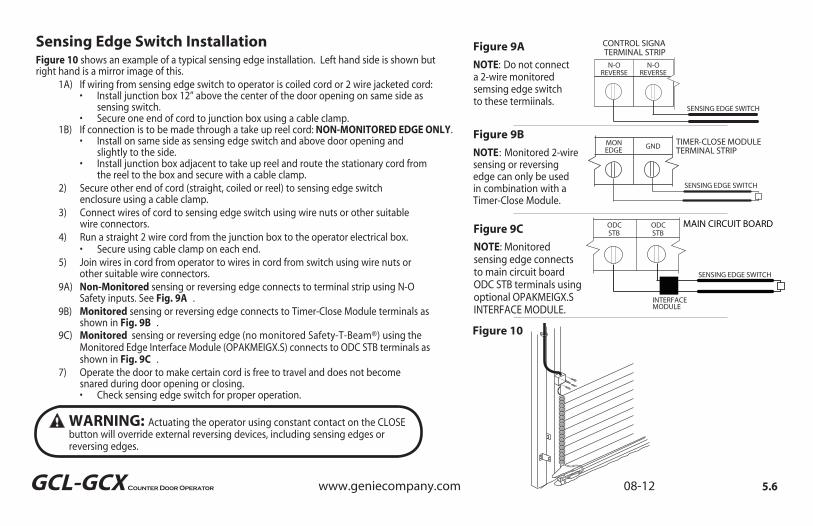
If connection is to be made through a take up reel cord: NON-MONITORED EDGE ONLY.
WARNING: Actuating the operator using constant contact on the CLOSE button will override external reversing devices, including sensing edges or reversing edges.
SENSING EDGE SWITCH
N-OREVERSE
N-OREVERSE
CONTROL SIGNA TERMINAL STRIP
Figure 9B
NOTE : Monitored 2-wiresensing or reversing edge can
Figure 9A
NOTE: Do not connect a 2-wire monitored semsing edge switch to these termiinals.
only be used in combination with a Timer-Close Module.
Figure 10
SENSING EDGE SWITCH
TIMER-CLOSE MODULE TERMINAL STRIP
GNDMONEDGE
VER VER
TERM NAL STR P
Figure 10 shows an example of a typical sensing edge installation. Left hand side is shown but right hand is a mirror image of this. 1A) If wiring from sensing edge switch to operator is coiled cord or 2 wire jacketed cord: • Install junction box 12” above the center of the door opening on same side as sensing switch. • Secure one end of cord to junction box using a cable clamp. 1B) • Install on same side as sensing edge switch and above door opening and slightly to the side. • Install junction box adjacent to take up reel and route the stationary cord from the reel to the box and secure with a cable clamp. 2) Secure other end of cord (straight, coiled or reel) to sensing edge switch enclosure using a cable clamp. 3) Connect wires of cord to sensing edge switch using wire nuts or other suitable wire connectors. 4) Run a straight 2 wire cord from the junction box to the operator electrical box. • Secure using cable clamp on each end. 5) Join wires in cord from operator to wires in cord from switch using wire nuts or other suitable wire connectors.
9A)
9B)
Non-Monitored sensing or reversing edge connects to terminal strip using N-O Safety inputs. See Fig. 9A .
9C)
Monitored sensing or reversing edge connects to Timer-Close Module terminals as shown in Fig. 9B .
Monitored sensing or reversing edge (no monitored Safety-T-Beam®) using the Monitored Edge Interface Module (OPAKMEIGX.S) connects to ODC STB terminals as
shown in Fig. 9C .
7) Operate the door to make certain cord is free to travel and does not become
snared during door opening or closing. • Check sensing edge switch for proper operation.
Sensing Edge Switch Installation
5.6
NOTE: Monitored sensing edge connects to main circuit board ODC STB terminals using optional OPAKMEIGX.S INTERFACE MODULE.
ODCSTB
ODCSTB
SENSING EDGE SWITCH
INTERFACE MODULE
MAIN CIRCUIT BOARDFigure 9C
www.geniecompany.com 08-12Counter Door OperatorGCL-GCX

GCL-GCX
Figure 11 shows an example of a typical locking bottom bar. Left hand side Interlock
Switch is shown. Right hand mount is mirror image.
Locking Bottom Bar / Interlock
NOTE: Interlock Switch is mandatory on doors equipped with an electronically controlled commercial operator.
OPEN CLOSE STOP GND 1 BTN N O SAFETY
N O SAFETY
ODCSTB
ODCSTB
EXTINTLK
EXTINTLK
CONTROL SIGNAL TERMINAL STRIP
* REMOVE JUMPER WHENINSTALLING EXTERNAL INTERLOCK
*
T-HANDLE TYPE LOCKING BOTTOM BAR
SLIDE TYPE LOCKING BOTTOM BAR
Figure 11
5.7www.geniecompany.com 08-12Counter Door Operator

GCL-GCX
RADIO CONNECTOR
S YSS B S BS S B
TBNAB
+ 4ACXT
N LKOI T
N LK
CALRUN
SETCLR
CROLL
CROLL
To Add the External Radio 1) Plug the pigtail with the 3-terminal strip attached (provided) onto the plug connector marked “EXT RAD.” Fig. 12. 2) Make wiring connections to the terminal strip per the diagram below.
External Radio Installation
EXT RAD O CONNECTOR
PWR 20-40 VDC @ 315mA MAX CURRENT
RELAY
GNDNOM+ 24VDC
RADIO
Blu
e
Ora
ng
e
Yello
w
Figure 12
IMPORTANTSAFETY INSTRUCTIONS
WARNING - To reduce the risk of severe injury or death:
1) READ AND FOLLOW ALL INSTRUCTIONS.2) Never let children operate or play with door controls. Keep the
remote control (where provided) away from children. 3) Personnel should keep away from a door in motion and keep the moving door in sight until it is completely closed or opened. NO ONE SHOULD CROSS THE PATH OF A MOVING DOOR.4) Test the door’s safety features at least once a month. After adjusting either the force or the limit of travel, retest the door operator’s safety features.5) For products having a manual release, if possible, use the manual release only when the door is closed. Use caution when operating the release while the door is open. Weak or broken springs may cause the door to fall rapidly, causing severe injury or death.6) KEEP DOOR PROPERLY OPERATING AND BALANCED. See Door Manufacturer’s Owner’s Manual. An improperly operating or improperly balanced door could cause severe injury or death. Have only trained door systems technicians make repairs to cables, spring assemblies, other hardware and any wooden blocks or like items to which they may be attached.7) SAVE THESE INSTRUCTIONS.
5.8www.geniecompany.com 08-12Counter Door Operator

GCL-GCX
OPEN
CLOSE
STOP
CALRUN SCROLL
SCROLL
SETCLEAR
Section 6: Operator Setup Procedure
These operators include a full function control panel including a liquid crystal display (LCD), calibration keys and Open, Close and Stop keys for on board operator control. See Fig. 1. The open, close and stop keys function as a 3-button wall control. The Display will show current operator conditions and calibration information. Due to limited character space, some displays will be abbreviated. See Appendix C (pgs. 10.5-10.7) for full display descriptions.The operators also include a non-volatile memory. The unit will remember all calibration settings plus error code and run code logs, if power is removed from unit.
DANGER: After power is supplied to the operator, Do Not make contact with components inside the control panel except for the Keypad Keys. Fig. 1.
Control Operating Modes Operator control boards operate in two modes: Run Mode and Calibration Mode. The control board should normally operate in the Run Mode. The operator is calibrated in Calibration Mode.With the operator standing idle: PRESS CAL/RUN TO TOGGLE BETWEEN OPERATING MODES. • ”.RID ESOLC TES“ si edom noitarbilac ni yalpsid tsrif ehT
• The display in run mode will be one of the condition codes listed in Appendix C.
Control Panel
Apply Power to the Operator Now
Operation Keys, operate unit like a 3-button wall station.
Scroll Keys, used in Calibration Mode.
Set/Clear Key, used to reset and adjust calibration settings.
Figure 1
Calibration & Run Mode Toggle Key.
Display Backlighting Toggle Key.
LCD DISPLAY
WARNING: DO NOT calibrate operator or operate door unless doorway is in sight and free of obstructions. Keep people clear of opening while door is moving.
6.1www.geniecompany.com 08-12Counter Door Operator

GCL-GCX
OPEN
CLOSE
STOP
CALRUN SCROLL
SETCLEAR
Setting Close Direction
SET CLOSE DIR Figure 2
OPEN
CLOSE
STOP
CAL SET
HIT CLOSE KEY
OPEN
CLOSE
STOP
CAL SET
DID DOOR CLOSE?
Figure 3
Figure 4
OPEN
CLOSE
STOP
CALRUN SCROLL
SCROLL
SETCLEAR
Figure 5
SCROLL KEY
CALRUN
CLOSE
SCROLL
SCROLL
SETCLEAR
CALRUN
YES NO
The direction of motor rotation depends on mounting position. This setting is
used to insure the door is closing and opening according to the input commands.
1) If operator is in RUN mode, press CAL/RUN to enter calibration mode. 2) Press SCROLL until “SET CLOSE DIR” is displayed. Figure 2.
SETCLEAR 2) Press SET/CLEAR to begin the calibration procedure and advance to
the next screen. Figure 3. 3 ) Briefly press the CLOSE key. (Pressing the Scroll key at this point will exit this control function.) • The display will read “ DID DOOR CLOSE? “ Figure 4 4) Press SCROLL key (up or down) to toggle between YES and NO. Figure 5. • If YES is selected, no change to operator calibration is made. If NO is selected — the POD will change the operator’s down direction. 5) Press the SET/CLEAR key. 6) Press CAL/RUN to return to run mode or, press SCROLL to shift to another function.
6.2
SCROLL
www.geniecompany.com 08-12Counter Door Operator

GCL-GCX
OPEN
CLOSE
STOP
CALRUN SCROLL
SCROLL
SETCLEAR
Setting Travel Limits
UP LIMIT SET
Figure 7
OPEN
CLOSE
STOP
CALRUN SCROLL
SCROLL
SETCLEAR
DOWN LIMIT SET
Figure 8
NOTE: The recommended setpoint for the DOWN Travel Limit is normally at approximately 2 inches off the floor. This final distance will be covered by the Limit Overrun Function to establish a more accurate seal.
CALRUN
CAL
CROL
SETCLEAR
OPEN
CROLL
CALRUN
CLOSE
Resetting Travel Limits
CALRUN
CAL
SCROLL
OPEN
SETCLEAR
CALRUN
CLOSE
SETCLEAR
UP and/or DOWN 1) If operator is in RUN mode, press CAL/RUN to enter calibration mode. 2) Press SCROLL until display reads “UP LIMIT>CLR ” or “DOWN LIMIT>CLR ” Figure 7. 3) Jog the door using the OPEN or CLOSE key until you reach the desired height. 4) Press SET/CLEAR key to switch display to “UP LIMIT>SET “ or “DOWN LIMIT>SET .“ Figure 8. 5) Press a SCROLL key to shift to a new function and lock in the limit setting. 6) Press CAL/RUN to return to run mode.
UP and/or DOWN 1) If operator is in RUN mode, press CAL/RUN to enter calibration mode. 2) Press SCROLL until display reads “UP LIMIT>SET ” or “DOWN LIMIT>SET.” Figure 8. 3) Press SET/CLEAR to switch display to ”UP LIMIT>CLR” or ”DOWN LIMIT>CLR” 4) Jog the door using the OPEN or CLOSE key until you reach the desired height. 5) Press SET/CLEAR to switch display to ”UP LIMIT>SET” or ”DOWN LIMIT>SET” 6) Press CAL/RUN to return to run mode.
6.3www.geniecompany.com 08-12Counter Door Operator

GCL-GCX
OPEN
CLOSE
STOP
CALRUN SCROLL
SCROLL
SETCLEAR
Setting Limit Overrun
LIMIT OVERRUN #
Figure 9
NOTE: The actual distance that the Overrun function covers is variable depending on model of operator and size of the door (nominally about 2 inches of travel).
WARNING: The Limit Overrun function will override external reversing devices, including photocells and sensing or reversing edges. Therefore, any externally connected devices will be disabled during that portion of door travel which is controlled by the Limit Overrun function.
CALRU
CROLL
SETCLEAR
SCROLL
CLO E
CALRUN
R
This Setting is a matter of trial and Error 1) If operator is in RUN mode, press CAL/RUN to enter calibration mode. 2) Press SCROLL until display reads “LIMIT OVERRUN>#” where # is the increment of travel beyond the CLOSE Limit ranging from 0 to 9. Zero turns off the Overrun function and the door stops at the DOWN Limit. Nine is the maximum distance the door will travel passed the limit. This function is used to insure a good seal at the bottom of the door. Figure 9. 3) Press SET/CLEAR key to toggle between 0 and 9—one digit at a time. 4) Pick a value and operate the door. Adjust as necessary. 5) Press a SCROLL key to shift to a new function and lock in the setting. 6) Press CAL/RUN to return to run mode.
EN
CALRUN
S ROLL
R
SET
6.4www.geniecompany.com 08-12Counter Door Operator

“CLOSE MODE>C-STP” or “CLOSE MODE>C-REV.” 2) Press SCROLL until display reads “CLOSE MODE>MOM,”
2) Press SCROLL until display reads “OPEN MODE>MOM”
6.5
OPEN
CLOSE
STOP
CALRUN SCROLL
SCROLL
SETCLEAR
Setting Open and Close Modes (Constant vs Momentary Contact)
OPEN MODE MOM
Figure 10
NOTE: Momentary contact (MOM) or Constant Reverse (C-REV) may not be used unless both the OPEN and CLOSE Limits have been set.In situations where an external reversing device is either not installed or not operating properly, Constant Contact (C-STP) MUST BE USED.
NOTE:
:
During
NOTE THIS OPERATOR MUST COMPLETE 2 FULL TRAVEL CYCLES BEFORE THE MODE CAN BE SET.
adjustment of a Travel Limit, the Open and Close Modes will automatically fail-safe to Constant Contact until the Limit has been set or reset. At that time the Open and Close Modes will revert to their previous setting.
CALRUN
OPEN CLOSE
SETCLEAR
SCROLL
CALRUN
CALRUN
OPEN CLOSE
SETCLEAR
SCROLL
CALRUN
WARNING: If momentary contact close control is to be used, a monitored external reversing device such as a photocell system or sensing edge switch must be used. See pages 5.5-5.6 for installation of entrapment protection devices.
OPEN 1) If operator is in RUN mode, press CAL/RUN to enter calibration mode.
“OPEN MODE>C-STP.”Figure 10.• MOM=momentary contact, meaning you press and release the
OPEN or CLOSE key and the door will continue to move until it reaches its travel limit. (See NOTE)
• C-STP=constant contact-stop, meaning if you release the key prior to the door reaching its travel limit, the door will stop. 3) Press SET/CLEAR key to toggle between “OPEN MODE>C-STP” or “OPEN MODE>MOM” on the display. 4) Press a SCROLL key to shift to a new function and lock in the setting. 5) Press CAL/RUN to return to run mode.
CLOSE 1) If operator is in RUN mode, press CAL/RUN to enter calibration mode.
Figure 10. MOM=momentary contact, meaning you press and release the
OPEN or CLOSE key and the door will continue to move until it reaches its travel limit. (See NOTE)
• C-STP=constant contact-stop, meaning if you release the key prior to the door reaching its travel limit, the door will stop.
• C-REV=constant contact-reverse, meaning if you release the key prior to the door reaching its travel limit, the door will reverse direction. (See NOTE)
3) Press SET/CLEAR key to toggle between “CLOSE MODE>C-STP” or “CLOSE MODE>C-REV” or ”CLOSE MODE>MOM” on the display. 4) Press a SCROLL key to shift to a new function and lock in the setting.
5) Press CAL/RUN to return to run mode.
SCROLL
SCROLL
www.geniecompany.com 08-12Counter Door OperatorGCL-GCX

GCL-GCX
OPEN
OPEN
CLOSE
STOP
CALRUN SCROLL
SCROLL
SETCLEAR
Setting Mid-Stop Limit
MID-STOP SET
Figure 14
CALRUN
SCROL
SETCLEAR
RUN
CLOSE
CALRUN
CALRUN
AL
SETCLEAR
SCROLL
The operator includes a programmable Mid-Stop. This feature allows the operator to stop at a user selectable point when opening. It is used when operating very tall doors that only open to their full height occasionally. The Mid-Stop does not effect the operator when closing. To operate door to full open position from mid-stop, press open button again.
NOTE: Setting of the MID-STOP should only be performed AFTER TravelLimit and Max Run Timer settings have been made. 1) Press CAL/RUN to enter calibration mode. 2) Press the CLOSE to close the door to the down limit. 3) Press SCROLL until display reads “MID-STOP >CLR” Figure 14
NOTE: If the display reads MID-STOP > SET at this point, first clear MID-STOP as described below then repeat steps 1-3 and continue.
4) Press the OPEN to open the door to desired mid-stop height. 5) Press SET/CLEAR until the display reads ”MID-STOP > SET” 6) Press CAL/RUN to return to run mode.To CLEAR the Limit 1) Press CAL/RUN to enter calibration mode. 3) Press SCROLL until display reads “MID-STOP >SET” 5) Press SET/CLEAR until the display reads ”MID-STOP > CLR” 8) Press CAL/RUN to return to run mode.
6.6www.geniecompany.com 08-12Counter Door Operator

GCL-GCX
OPEN
CLOSE
STOP
CALRUN SCROLL
SCROLL
SETCLEAR
MAX RUN TMR SET
Figure 15
Resetting the MRT (The Max Run Timer is set automatically once the unit is cycled between Limits. The Max Run Timer prevents the unit from running continuously in the event of a problem. The MRT’s are set to the time required to run from one limit to the other, plus 5 seconds (nominal). When the MRT is exceeded, the operator stops and will not respond to any command until it is reset by pressing one of the calibration keys or by cycling power to the unit.
CAUTION: The MID-STOP feature must be turned off in order to properly set the Max Run Timer.
CALRUN
ALUN
LL
SCROLL
SETCLEAR
O
CALRUN
ROLL
OPEN
CLOSE
STOP
CALRUN SCROLL
SCROLL
SETCLEAR
ODC STB ON
Figure 16
NOTE Installation of Series II Monitored Photocells DOES NOT make the GCX unit legal for residential use. The Genie® Company strictly prohibits any installation of a commercial unit in any residentially zoned construction.
Monitored Reversing Devices
WARNING: Photocell systems provide entrapment protection when mountednear the doorway in such a way that the lower portion of an individuals leg willbreak the photocell beam during normal walking through the doorway.
CALRUN
CAL
SETCLEAR
SCROLL
OP N
LOS
CALRUN
SCROLL
C O
C A
CARUN
CROLL
TO RESET 1) Press CAL/RUN to enter calibration mode. 2) Press SCROLL (up or down) until display reads ”MAX RUN TMR > SET.” Fig. 15. 3) Press SET/CLEAR until display reads ”MAX RUN TMR > CLR.” 4) Press CAL/RUN to return to RUN mode. 5) Cycle the door between limits. NOTE:
:
The Max Run Time must be reset each and every time the Travel Limits are adjusted.
ODC Safe-T-Beams® (OPTIONAL) 1) If operator is in RUN mode, press CAL/RUN to enter calibration
2) Press SCROLL (up or down) until display reads “ODC STB>ON” “ODC STB>OFF” Figure 16
3) Press SET/CLEAR key to toggle between ON and OFF.4) Press SCROLL (up or down) to shift to a new function and lock setting.5) Press CAL/RUN to return to run mode.
6.7
Current UL Approved Monitored Reversing Devices:
1) MillerEdge ME and MT series monitored edge sensors used in combination with Timer-Close Module P/N OPABTCX.S.
2) MillerEdge ME and MT series monitored edge sensors used in combination with OPAKMEIGX.S Interface Module. (Direct connect through STB inputs).
5) Monitored Photocells P/N OPAKPEN4GX.S.
3) Residential Safe-T-Beam® Monitored Photocells from The Genie® Company, model OSTB-BX (P/N 38176R.S).
4) Series II Safe-T-Beam® Monitored Photocells (P/N OPAKPE.S).
www.geniecompany.com 08-12Counter Door Operator

GCL-GCX
Section 7: Special Operator Features (No user input)
OPEN
CLOSE
STOP
CYCLES 1
Figure A
OPEN
CLOSE
STOP
GDO V# #########
OPEN
CLOSE
STOP
CALRUN SCROLL
SETCLEAR
DISPLAY V# #######
Figure B
Operator Cycle Count
GDO and Display Firmware
CALRUN
R N
SCROLL
P
CALRUN
CALRUN
CN
SCROLL
CALRUN
1) Press CAL/RUN to enter calibration mode. 2) Press SCROLL until display reads “GDO V# > ######.” Figure B. This display will cycle between the version number of the current GDO firmware and the current Display Firmware. 3) Press CAL/RUN to return to run mode.
1) Press CAL/RUN to enter calibration mode. 2) Press SCROLL until display reads “CYCLES>1,2,3 etc. where the number is the number of open/close cycles the operator has performed. Figure A. 3) Press CAL/RUN to return to run mode.
7.1www.geniecompany.com 08-12Counter Door Operator

GCL-GCX
OPEN
CLOSE
STOP
CALRUN SCROLL
SCROLL
SETCLEAR
GDO TYPE J-SHAFT
Figure 3
Operator Type Fig. 3
CALRUN
CALRUN
SCROLL
S
SETCLEAR
Operator circuit boards are available for use in jackshaft or trolley configurations. The same control board is used for either configuration, however the control board must be set for the appropriate GDO configuration. A board set for trolley mode will not work in a jackshaft operator and vice-versa. NOTE: The GDO type is factory set. The installer should not have to set this feature. However, if the GDO type is inadvertently changed, or if a board needs to be replaced in the field, follow these instructions to set GDO type. 1) Press CAL/RUN to enter calibration mode. 2) Press SCROLL until display reads “GDO TYPE > .” This will display the current GDO type. 3) Press SET/CLEAR until display indicates correct GDO type
.)TFAHS-J ( 4) Press CAL/RUN to return to run mode.
7.2www.geniecompany.com 08-12Counter Door Operator

OPEN
CLOSE
STOP
CALRUN SCROLL
SCROLL
SETCLEAR
OPEN
CLOSE
STOP
CALRUN SCROLL
SCROLL
SETCLEAR
Section 8: Troubleshooting
These operators display their status on the integrated display. Each time the operator runs, stops, reverses or refuses to run, the display will indicate why the action did, or did not, take place.Once an error code has been generated, the operator will continue to display the error code while the operator is not running. This error code can be cleared by pressing the STOP button or STOP key on the keypad. The error code will automatically clear when the operator stops at the down limit. Error codes will continue to be stored in the operator’s Error Code Memory after they have been cleared from the display in the Run Mode.
Display Operation in Run Mode
To aid in troubleshooting problems, these operators include an error code memory that stores the last 10 error events. These codes are stored with or without power. The last error code detected is also displayed on the LCD until the stop button or key is pressed or the operator stops at the down limit.The error code memory stores the last 10 error codes in sequence. Once 10 codes are stored, the oldest code is erased to make room for the newest code. These codes are displayed in calibration mode. The display will flash the number of the error code and the 2-digit error code followed by a description of the error code. Fig. 1 & 2.
Error Codes
ERROR CODE 1 41
Figure 1
REV ONE BUTTON
Figure 2
3.18.1www.geniecompany.com 08-12Counter Door OperatorGCL-GCX

GCL-GCX
OPEN
CLOSE
STOP
CALRUN SCROLL
SCROLL
SETCLEAR
OPEN
CLOSE
STOP
CALRUN SCROLL
SCROLL
SETCLEAR
The operators also include a run code memory that stores the last 10 run events. These codes are stored with or without power. Each time the operator runs or stops, it generates a code that it stores in this memory (Why the operator ran or stopped). Used together with the error code memory, it becomes a powerful troubleshooting aid. The run code memory stores the last 10 codes in sequence. Once 10 codes are stored, the oldest code is erased to make room for the newest code. These codes are displayed in calibration mode. The display will flash the number of the run code and the 2-digit run code followed by a description of the run code. Fig. 3 & 4.
Run Codes
RUN CODE 1 3C
Figure 3
HALT DOWN LIMIT
Figure 4
Error Codes (continued)
CALRUN
SCROLL
CR
SETCLEAR
CALRUN
To view the error code memory: 1) Press CAL/RUN to enter calibration mode. 2) Press SCROLL until display reads “ERROR CODE 1 >”. • The display will begin flashing the error code number and 2-digit error code followed by its description. • Reminder: Error code number 1 is the latest code generated. 3) Press SET/CLEAR . The display will now read “ERROR CODE 2 > .” (This is the error code which was generated before error code 1.) 4) Repeat step 3 until all 10 error codes have been displayed or move on to step 5 when ready. 5) Press CAL/RUN to return to run mode.
NOTE: For all error codes see Appendix C, Sections 10.6 - 10.7.
8.2www.geniecompany.com 08-12Counter Door Operator

GCL-GCX
TROUBLESHOOTING EXAMPLE USING RUN AND ERROR
CODE MEMORIES. Fig. 51. In Calibration Mode, display and write down each Run Code and Error Code stored in memory.2. List as shown in Fig. 5.3. Refer to Appendix C to interpret the codes.In this example, the operator was opened using the OPEN key on the keypad and stopped at the up limit. The OPEN wall button was then activated, causing the “6D” code to be generated since the operator could not open when it is already at the up limit. The CLOSE wall button was then activated, causing the operator to close. While closing, the Normally-Open (N-O) Safety Input was activated, causing the operator to stop and then reverse, stopping at the up limit.
ERRORCODES
RUNCODES
1
2
3
4
5
6
7
8
9
10
1
2
3
4
5
6
7
8
9
10
45
6D
00
00
00
00
00
00
00
00
00
00
00
00
00
3D
35
20
3D
14
REVERSED DUE TO ACTIVE N-O SAFETY INPUT
WOULD NOT OPEN —ALREADY AT UP LIMIT
STOPPED AT UP LIMIT
STOPPED DUE TO ACTIVE N-O SAFETY INPUT
CLOSED FROM CLOSE WALL BUTTON
STOPPED AT UP LIMIT
OPENED FROM OPEN KEY ACTIVATION
OPERATOR STORES “00” CODES IN UNUSED RUN AND ERROR CODE MEMORY LOCATIONS AT THE TIME OF MANUFACTURE. AS ERROR OR RUN CODES ARE RECORDED, THE “00” CODES ARE REPLACED WITH VALID CODES
NUMBER CODE NUMBERCODE
Figure 5
Run Codes (continued)
CALRUN
L
SCROLL
SETCLEAR
S OP
CALRUN
SETCLEAR
To view the run code memory: 1) Press CAL/RUN to enter calibration mode. 2) Press SCROLL until display reads “RUN CODE 1 > .” • The display will begin flashing the run code number and code followed by its description. • Remember: run code number 1 is the latest code generated. 3) Press SET/CLEAR . The display will now read “RUN CODE 2 > .” (This is the run code which was generated before run code 1.) 4) Repeat step 3 until all 10 run codes have been displayed or move on to step 5 when ready. 5) Press CAL/RUN to return to run mode.
NOTE: For all run codes see Appendix C, Section 10.5.
8.3www.geniecompany.com 08-12Counter Door Operator

GCL-GCX
The operators include a self-diagnostic circuit board using troubleshooting LED indicators to signal the technician of a problem.
LED Indicators Fig. 6
TROUBLESHOOTING LEDs
S YS YS B S BS S B
S BE AB+ 24VACEXTNTLK
HO STNTLK
CALRUN
SETCLR
SCROLL
SCROLL
Figure 6
+ 24 VOLTSDC
STBENABLE
1. CHECK AC POWER SUPPLY
8.4
STB ENABLED STB DISABLED
POWER AVAILABLE
EXTINTLK
HOISTINTLK
1. INTLK SWITCH OPEN
INTLK ENABLED 1. INTLK SWITCH OPEN 2. CHECK POWER SUPPLY 3. CHECK MAIN POWER FUSE 4. CHECK SECONDARY FUSE (2A)
INTLK ENABLED 2. HOIST RELEASE NEEDS RESET 3. INTLK CONNECTOR NOT PLUGGED IN 4. INTERLOCK DEFECTIVE
LED ON OFF
2. CHECK FUSES
www.geniecompany.com 08-12Counter Door Operator

GCL-GCX
Safe-T-Beam® Monitored Photocell Self-diagnostic Troubleshooting Chart
ON ON NORMAL OPERATION NONE REQUIRED
OFF OFF1. POWER HEAD NOT POWERED 2. WIRING FROM POWER HEAD BAD
1. CHECK BREAKERS, FUSES, PLUGS 2. CHECK WIRING FOR OBVIOUS SHORTS
OFF ON 1. WIRING TO SOURCE MISSING OR BAD 2. POWER HAS BEEN INTERRUPTED
1. CHECK WIRING 2. REMOVE POWER AND REAPPLY
2 BLINKS, PAUSE (REPEAT)
ON1. BEAM NOT ALIGNED 2. BEAM OBSTRUCTED 3. SENSOR DEFECTIVE
1. CHECK ALIGNMENT 2. CHECK FOR OBSTRUCTION 3. CALL CUSTOMER SERVICE
1. WIRE TO SENSOR MISSING OR BAD 2. SENSOR DEFECTIVE
1. CHECK WIRING 2. CALL CUSTOMER SERVICEOFF
ON1. SENSOR RECEIVING INTERFERENCE 1. ATTEMPT TO DETERMINE SOURCE OF
INTERFERENCE 2. CALL CUSTOMER SERVICE
ON 1. SOURCE NOT SENDING PULSES 2. SOURCE DEFECTIVE
1. CALL CUSTOMER SERVICE 2. CALL CUSTOMER SERVICE
SOURCE (RED LED) SENSOR (GREEN LED) INDICATED CONDITION REQUIRED ACTION
2 BLINKS, PAUSE (REPEAT)
3 BLINKS, PAUSE (REPEAT)
4 BLINKS, PAUSE (REPEAT)
WARNING: ACTUATING THE OPERATOR BY USING CONSTANT CONTACT ON THE CLOSE BUTTON WILL OVERRIDE EXTERNAL REVERSING DEVICES, INCLUDING PHOTOCELLS.
WARNING: THE GENIE® COMPANY RECOMMENDS THAT LINE VOLTAGE WIRING BE PERFORMED BY A QUALIFIED ELECTRICIAN. SEE SECTION 5 FOR ADDITIONAL WIRING INSTRUCTIONS.
8.5www.geniecompany.com 08-12Counter Door Operator

9.1
Section 9: Service and MaintenanceMaintenance Schedule
The following table provides a schedule of recommended Service and Maintenance items to be completed by a trained service representative.
CAUTION: Failure to perform the recommended Service & Maintenance may result in premature failure of the operator.
SERVICE ITEM SERVICE INTERVAL (FREQUENCY) EVERY 6 MO. EVERY 12 MO. EVERY 36 MO. MONTHLY OR OR OR 5,000 CYCLES 10,000 CYCLES 30,000 CYCLE MANUAL OPERATION OF DOOR CHECK DRIVE CHAINS AND LUBRICATE * PHOTOCELL/ SENSING EDGE OPERATION
CHECK FOR LOOSE OR MISSING HARDWARE CHECK LIMIT POSITION GEAR TRAIN WEAR
* If Installed.
www.geniecompany.com 08-12Counter Door OperatorGCL-GCX

GCL-GCXGCL-GCX
Section 10: Appendix AOperator Parts Breakdown (Exploded
View)
23
158
156
10.1
1
3
13
19 32
35
12
86
143142
91109
141
144 145
150
157
15916499
32
www.geniecompany.com 08-12Counter Door Operator

GCL-GCXGCL-GCX
Section 10: Appendix AOperator Parts Breakdown (Parts List)
10.2
ELECTRIC MOTOR13
12131923323586
9199
109141142
143144145
150
156
KIT, PCBTRANSFORMER
CHAIN GUARD
OUTPUT SHAFT
OUTPUT SPROCKETOPERATOR CHASSIS, COVER
157158159
164
TEM NO. DESCRIPTIONPART NUMBER
PARTS LIST
** CONTACT DEALER FOR PROPER PART BASED ON YOUR SPECIFIC MODEL.
108802.0001
112365.0001.S111421.0001.S108563.0001
110846.0001.S
108819.0001
107871.0001.S
111933.0001
108608.0001.S
108822.0001.S106062.0002.S
108807.0001.S
108609.0001108802.0001
108796.0001
LIMIT MODULE KIT
CAPACITORRELEASE LEVERSHAFT BEARINGCOVER POWERHEADOUTPUT HELICAL GEAR
WORM GEAR
MAIN CIRCUIT BOARD INSULATORDENTILOUTPUT PINION THRUST WASHERSET COLLARWASHER, NYLON
105961.0001077852.0000106124.0007
111629.0001108855.0001
MAIN FRAMEFRAME SIDE MOUNTING, RH
FRAME ASSY, MTR & GEAR
111679.0002
111950.0001
111932.0001FRAME SIDE MOUNTING, LH111932.0002
MAIN FRAME, BACK
www.geniecompany.com 08-12Counter Door Operator
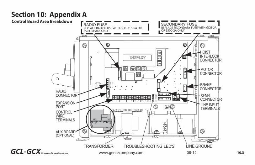
GCL-GCXLINE GROUNDTROUBLESHOOTING LED'STRANSFORMER
SA ESA ES B S B N KO EN C OSE S O GND B N N O N O ODC ODC EX EXN K
N
CONTROL WIRE
AUX BOARD(OPTIONAL)
TERMINALS
STBENAB+ 24VACEXTNTLK
HO STNTLK
RADIO FUSE SECONDARY FUSEREPLACE RADIO FUSE WITH GDC-315mA ORS504-315mA ONLY
REPLACE SECONDARY FUSE WITH GDB-2A OR S500-2A ONLY
EXPANSIONPORT
RADIO CONNECTOR
CALRUN
SETCLR
SCROLL
SCROLL
HOISTINTERLOCK CONNECTOR
MOTORCONNECTOR
LINE INPUTTERMINALS
XFMRCONNECTOR
BRAKECONNECTOR
Control Board Area BreakdownSection 10: Appendix A
10.3www.geniecompany.com 08-12Counter Door Operator

GCL-GCX
Section 10: Appendix BScrew Terminal Assignments
FUNCTION CONNECTION TYPE11-POSITION TERMINAL BLOCK INSIDE ELECTRIC BOX
OPEN Causes door to open if not at Up Limit. Causes a closing door to reverse.CLOSE Causes door to close if not at Down Limit. Normally-Open Dry Contact to GND.
Normally-Open Dry Contact to GND.
STOP Causes a moving door to stop. Prevents the operator from running. Normally-Closed Dry Contact to GND.GND Common ground connection for Open, Close, Stop & 1-Btn Inputs.
1-BTNCauses door to open if not at Up Limit or Mid-Stop Limit. Causes door to close if at Up Limit or Mid-Stop Limit. Causes door to stop if opening. Causes a closing door to reverse.
Normally-Open Dry Contact to GND.
ODC STB
Reverses a closing door if photocell beam is blocked. NOTE: STB's must be enabled in Calibration Mode.
ODC Series II Safe-T-Beams® ONLY to these inputs.
ODC STB
Reverses a closing door if photocell beam is blocked.NOTE: STB's must be enabled in Calibration Mode.
N-O REVERSE Causes a closing door to reverse. NOTE: Will not open a stopped door. Normally-Open 2-Wire Non-Monitored Edge Sensor.
N-O REVERSE Causes a closing door to reverse. NOTE: Will not open a stopped door. Normally-Open 2-Wire Non-Monitored Edge Sensor.
EXT INTLKCauses a moving door to stop. Prevents the operator from running when contact is open. Operates even if microcontroller is non-functional.
Normally-Closed dry contacts. (board will energize these contacts at nominal +24VDC).
EXT INTLKCauses a moving door to stop. Prevents the operator from running when contact is open. Operates even if microcontroller is non-functional.
Normally-Closed dry contacts. (board will energize these contacts at nominal +24VDC).
2-POSITION TERMINAL L1 / L1 120VAC: Connect to Line (Hot) Power to operator.BLOCK (INSIDE ELECTRIC BOX) N / L2 120VAC: Connect to Neutral Power to operator.
PWR Power for radio & other accessories. +20 to +40VDC, fused at 315mA (F1). Connect to radio or other accessory's power input.
RAD
GND
Causes door to open if not at Up Limit or Mid-Stop Limit. Causes door to close if at Up Limit or Mid-Stop Limit. Causes a closing door to reverse.Common ground connection for PWR and RAD terminals. Connect to radio or other accessory's ground input.
EXPANSION PORT Accessory Module Ribbon Cable.PLUG CONNECTIONSINSIDE ELECTRIC BOX TRANSFORMER Connects main transformer to control board. Transformer Plug.
BRAKE Connects brake solenoid to control board. Brake Solenoid Plug.Motor Plug.
HOIST INTLK Causes moving door to stop. Prevents the operator from running. Operates even if microcontroller is non-functional.
Limit Sensor Plug.
Hoist Interlock Plug or Jumper.
INPUT
(Radio Input Control)
(not polarity sensitive)
ODC Series II Safe-T-Beams® ONLY to these inputs. (not polarity sensitive)
(not polarity sensitive)
(not polarity sensitive)
LIMIT SENSOR Causes door to stop at top and bottom of normal travel.
MOTOR Connects motor and capacitor to control board.
Connects accessory modules to operator.
RADIO ANDACCESSORIES
PIGTAIL
10.4www.geniecompany.com 08-12Counter Door Operator

GCL-GCX
Section 10: Appendix CRun Code Displays
Condition Code DISPLAY Condition Code Description
0C IDLE > DOWN LIMIT STANDING BY AT DOWN LIMIT (NOTE: THIS MESSAGE IS DISPLAYED IF BOTH LIMITS ARE ACTIVE) 0D IDLE > UP LIMIT STANDING BY AT UP LIMIT 0E IDLE > MID STOP STANDING BY AT MID-STOP LIMIT 0F IDLE > NO LIMIT STANDING BY BETWEEN LIMITS 10 OPENING > OPEN BTN OPENING FROM OPEN BUTTON 11 OPENING > ONE BTN OPENING FROM 1 BUTTON 12 OPENING > RADIO OPENING FROM RADIO 13 OPENING > AUX OPEN OPENING FROM AUXILIARY OPEN INPUT 14 OPENING > OPEN KEY OPENING FROM KEYPAD OPEN KEY 20 CLOSING > CLOSE PB CLOSING FROM CLOSE BUTTON 21 CLOSING > ONE BTN CLOSING FROM 1 BUTTON 22 CLOSING > RADIO CLOSING FROM RADIO 24 CLOSING > CLOSE KP CLOSING FROM KEYPAD CLOSE KEY 2A CLOSING > TCM CLS CLOSING FROM TIMER CLOSE MODULE 2B CLOSING > FDM CLS CLOSING FROM FORE DOOR MODULE 30 HALT > WALL BUTTON GDO STOPPED BECAUSE STOP OR OPEN BUTTON WAS ACTIVATED, POSSIBLY STARTING A REVERSAL 31 HALT > ONE BUTTON GDO STOPPED BECAUSE 1 BUTTON WAS ACTIVATED, POSSIBLY STARTING A REVERSAL 32 HALT > RADIO GDO STOPPED BECAUSE RADIO INPUT WAS ACTIVATED, STARTING A REVERSAL 33 HALT > AUX. OPEN GDO STOPPED BECAUSE AUXILIARY OPEN INPUT WAS ACTIVATED, STARTING A REVERSAL 34 HALT > KEYPAD KEY GDO STOPPED BECAUSE KEYPAD STOP OR OPEN KEY WAS ACTIVATED, POSSIBLY STARTING A REVERSAL 35 HALT > N-O SAFETY GDO STOPPED BECAUSE N-O REVERSING INPUT WAS ACTIVATED, STARTING A REVERSAL 36 HALT > ODC STB GDO STOPPED BECAUSE ODC STB WAS BLOCKED, STARTING A REVERSAL 37 HALT > N-C SAFETY GDO STOPPED BECAUSE N-C REVERSING INPUT WAS ACTIVATED, STARTING A REVERSAL 38 HALT > MON. EDGE GDO STOPPED BECAUSE MONITORED EDGE SENSOR INPUT WAS ACTIVATED, STARTING A REVERSAL 39 HALT > DOOR FORCE GDO STOPPED BECAUSE THE FORCE REQUIRED TO OPERATE THE DOOR WAS TOO HIGH, POSSIBLY STARTING A REVERSAL 3A HALT > LOSS OF C/C GDO STOPPED BECAUSE CONSTANT CONTACT ON CONTROL REMOVED BEFORE REACHING A LIMIT, POSSIBLY STARTING A REVERSAL 3B HALT > SHUTDOWN GDO STOPPED BECAUSE THE GDO DETECTED A FAULT SUCH AS AN OPEN INTERLOCK, OVERHEATED MOTOR, ETC. 3C HALT > DOWN LIMIT GDO STOPPED BECAUSE IT REACHED THE DOWN LIMIT 3D HALT > UP LIMIT GDO STOPPED BECAUSE IT REACHED THE UP LIMIT 3E HALT > MID STOP GDO STOPPED BECAUSE IT REACHED THE MID-STOP LIMIT 3F HALT > MODULE FAIL GDO STOPPED BECAUSE AN EXPANSION MODULE WAS NOT WORKING PROPERLY 40 REV > OPEN BUTTON GDO REVERSED BECAUSE THE OPEN BUTTON WAS ACTIVATED 41 REV > ONE BUTTON GDO REVERSED BECAUSE THE 1 BUTTON WAS ACTIVATED 42 REV > RADIO GDO REVERSED BECAUSE THE RADIO INPUT WAS ACTIVATED 43 REV > AUX OPEN GDO REVERSED BECAUSE THE AUXILIARY OPEN INPUT WAS ACTIVATED 44 REV > OPEN KEY GDO REVERSED BECAUSE THE KEYPAD OPEN KEY WAS ACTIVATED 45 REV > N-O SAFETY GDO REVERSED BECAUSE THE N-O REVERSING INPUT WAS ACTIVATED
10.5www.geniecompany.com 08-12Counter Door Operator

www .geniecompany.com 08-12 10.6Counter Door OperatorGCL-GCX
Condition Code DISPLAY Condition Code Description 46 REV > ODC STB GDO REVERSED BECAUSE THE ODC STB WAS BLOCKED 47 REV > N-C SAFETY GDO REVERSED BECAUSE THE N-C REVERSING INPUT WAS ACTIVATED 48 REV > MON. EDGE GDO REVERSED BECAUSE THE MONITORED EDGE SENSOR WAS ACTIVATED 49 REV > DOOR FORCE GDO REVERSED BECAUSE THE FORCE REQUIRED TO CLOSE THE DOOR WAS TOO HIGH 4A REV > LOSS OF C/C GDO REVERSED BECAUSE CONSTANT CONTACT ON THE CONTROL WAS REMOVED BEFORE REACHING THE DOWN LIMIT 4B REV > MAX RUN TMR GDO REVERSED BECAUSE THE CLUTCH SLIPPED OR SOME OTHER FAULT OCCURRED THAT ALLOWED THE GDO TO RUN TOO LONG 4F REV > EXP MOD FAIL GDO REVERSED BECAUSE AN EXPANSION MODULE WAS NOT WORKING PROPERLY 50 STOP > HOT MOTOR GDO STOPPED BECAUSE THE MOTOR WAS OVERHEATED 51 STOP > OPEN MRT GDO STOPPED BECAUSE THE CLUTCH SLIPPED OR SOME OTHER FAULT OCCURRED THAT ALLOWED THE GDO TO RUN OPEN TOO LONG 52 STOP > CLOSE MRT GDO STOPPED BECAUSE THE CLUTCH SLIPPED OR SOME OTHER FAULT OCCURRED THAT ALLOWED THE GDO TO RUN DOWN TOO LONG 53 STOP > BRAKE FAULT GDO STOPPED BECAUSE OF BRAKE ERRONEOUSLY ENGAGED 57 STOP > OPEN INTLK GDO STOPPED BECAUSE THE HOIST INTERLOCK OR EXTERNAL INTERLOCK IS OPEN 58 STOP > WRONG GDO GDO STOPPED BECAUSE THE BOARD IS SET FOR JACKSHAFT MODE, BUT INSTALLED IN A TROLLEY OPERATOR 59 STOP > DOOR FORCE GDO STOPPED BECAUSE THE FORCE REQUIRED TO OPEN THE DOOR WAS TOO HIGH 5A STOP > WRONG LIMIT GDO STOPPED BECAUSE THE UP LIMIT ACTIVATED WHEN CLOSING OR THE DOWN LIMIT ACTIVATED WHEN OPENING 5B STOP > WRONG DIR GDO STOPPED BECAUSE THE DOOR MOVED IN THE WRONG DIRECTION 5C STALL > DOWN LIMIT GDO STOPPED BECAUSE IT COULDN'T LEAVE THE DOWN LIMIT DUE TO A SLIPPING CLUTCH OR OTHER PROBLEM 5D STALL > UP LIMIT GDO STOPPED BECAUSE IT COULDN'T LEAVE THE UP LIMIT DUE TO A SLIPPING CLUTCH OR OTHER PROBLEM 5E STALL > MID-STOP GDO STOPPED BECAUSE IT COULDN’T LEAVE THE MID-STOP LIMIT DUE TO A SLIPPING CLUTCH OR OTHER PROBLEM 5F STALL > NO LIMIY GDO STOPPED BECAUSE TRAVEL LIMITS HAVE NOT BEEN SET 60 CHECK STOP BTN GDO WON'T RUN BECAUSE THE STOP BUTTON IS ACTIVE 61 TCM DISABLED TIMER CLOSE WON'T WORK BECAUSE NO SAFETIES ARE ENABLED 62 NO RADIO >> C/C RADIO INPUT WON'T WORK WITH OPEN OR CLOSE FUNCTION IN CONSTANT CONTACT MODE 63 CHECK AUX OPEN GDO WON'T CLOSE BECAUSE AUXILIARY OPEN INPUT IS ACTIVE 64 CHECK STOP KEY GDO WON'T RUN BECAUSE THE KEYPAD STOP KEY IS ACTIVE 65 CHECK N-O SAFETY GDO WON'T CLOSE BECAUSE THE N-O REVERSING IS ACTIVE 66 CHECK ODC STB GDO WON'T CLOSE BECAUSE THE ODC STB IS BLOCKED 67 CHECK N-C SAFETY GDO WON'T CLOSE BECAUSE THE N-C REVERSING INPUT IS ACTIVE 68 CHECK MON. EDGE GDO WON'T CLOSE BECAUSE THE MONITORED EDGE SENSOR IS ACTIVE 69 OVERHEATED MOTOR GDO WON'T RUN BECAUSE THE MOTOR IS OVERHEATED 6A POWER WIRING ERROR GDO WON’T RUN BECAUSE POWER SUPPLY WIRED INCORRECTLY 6B FIRE DOOR SHTDN GDO WON’T RUN BECAUSE OF LOSS OF POWER 6C NO RUN > DOWN LIM GDO WON'T CLOSE BECAUSE ITS ALREADY AT THE DOWN LIMIT 6D NO RUN > UP LIMIT GDO WON'T OPEN BECAUSE ITS ALREADY AT THE UP LIMIT 6E NO RUN > MID STOP GDO WON'T RUN BECAUSE ITS AT OR ABOVE THE MID-STOP LIMIT & CAN'T RUN UP & A REVERSING INPUT IS PREVENTING IT FROM CLOSING 6F EXP MODULE FAIL GDO WON'T RUN BECAUSE AN EXPANSION MODULE FAILURE IS PREVENTING IT
Error Code DisplaysSection 10: Appendix C

www.geniecompany.com 08-12Counter Door OperatorGCL-GCX
Error Codes Displays (continued)Section 10: Appendix C
Condition Code DISPLAY Condition Code Description
70 BOARD FAILURE 70 CONTROL BOARD FAILURE 70, CONTACT FACTORY TECHNICAL SERVICE DEPT. 71 BOARD FAILURE 71 CONTROL BOARD FAILURE 71, CONTACT FACTORY TECHNICAL SERVICE DEPT. 74 BOARD FAILURE 74 CONTROL BOARD FAILURE 74, CONTACT FACTORY TECHNICAL SERVICE DEPT. 75 BOARD FAILURE 75 CONTROL BOARD FAILURE 75, CONTACT FACTORY TECHNICAL SERVICE DEPT. 76 BOARD FAILURE 76 CONTROL BOARD FAILURE 76, CONTACT FACTORY TECHNICAL SERVICE DEPT. 77 BOARD FAILURE 77 CONTROL BOARD FAILURE 77, CONTACT FACTORY TECHNICAL SERVICE DEPT. 80 BOARD FAILURE 80 CONTROL BOARD FAILURE 80, CONTACT FACTORY TECHNICAL SERVICE DEPT. 81 BOARD FAILURE 81 CONTROL BOARD FAILURE 81, CONTACT FACTORY TECHNICAL SERVICE DEPT. 82 BOARD FAILURE 82 CONTROL BOARD FAILURE 82, CONTACT FACTORY TECHNICAL SERVICE DEPT. 83 BOARD FAILURE 83 CONTROL BOARD FAILURE 83, CONTACT FACTORY TECHNICAL SERVICE DEPT. 84 BOARD FAILURE 84 CONTROL BOARD FAILURE 84, CONTACT FACTORY TECHNICAL SERVICE DEPT. 85 EXP PORT PROBLEM EXPANSION PORT IS SHORT CIRCUITED, TRY DISCONNECTING EXPANSION MODULES OR CONTACT FACTORY TECHNICAL SERVICE DEPT. 86 BOARD FAILURE 86 CONTROL BOARD FAILURE 86, DISCONNECT EXPANSION MODULES. IF NO CHANGE, CONTACT FACTORY TECHNICAL SERVICE DEPT. 87 IEM FAILURE RESERVED--NOT CURRENTLY USED 88 TCM FAILURE TIMER CLOSE MODULE (TCM) HAS FAILED 89 FDM FAILURE FIRE DOOR MODULE (FDM) HAS FAILED 8A AOM FAILURE AUXILIARY OUTPUT MODULE (AOM) HAS FAILED 8B SPARE MOD FAILURE RESERVED--NOT CURRENTLY USED 8C LOW SYSTEM VOLTS POWER SUPPLY LINE VOLTAGE LOW 8D HI SYSTEM VOLTS POWER SUPPLY LINE VOLTAGE HIGH 8E REV INTERRUPTED GDO LOST POWER OR ENCOUNTERED ANOTHER PROBLEM DURING THE REVERSAL PROCESS, REVERSAL IS COMPLETING NOW 8F LIMIT MOD. FAIL GDO WON'T RUN, LIMIT MODULE HAS FAILED 90 DIAGNOSTIC MODE GDO IS IN DIAGNOSTIC MODE, NORMAL FUNCTIONS ARE NOT ALLOWED A0 OPEN BTN BAD > PU OPEN & CLOSE BUTTONS WON'T WORK, THE OPEN BUTTON WAS ACTIVE WHEN THE GDO WAS POWERED-UP A1 CLOSE BTN BAD > PU OPEN & CLOSE BUTTONS WON'T WORK, THE CLOSE BUTTON WAS ACTIVE WHEN THE GDO WAS POWERED-UP A2 ONE BTN BAD > PU 1 BUTTON WON'T WORK, THE 1 BUTTON WAS ACTIVE WHEN THE GDO WAS POWERED-UP A3 RADIO BAD > PWR UP RADIO INPUT WON'T WORK, THE RADIO INPUT WAS ACTIVE WHEN THE GDO WAS POWERED-UP A4 AUX OPEN BAD > PU AUXILIARY OPEN INPUT WON'T WORK, THE AUXILIARY OPEN INPUT WAS ACTIVE WHEN THE GDO WAS POWERED-UP A5 OPEN KEY BAD > PU KEYPAD OPEN & CLOSE KEYS WON'T WORK, THE OPEN KEY WAS ACTIVE WHEN THE GDO WAS POWERED-UP A6 CLOSE KEY BAD > PU KEYPAD OPEN & CLOSE KEYS WON'T WORK, THE CLOSE KEY WAS ACTIVE WHEN THE GDO WAS POWERED-UP A7 MULT KEYS BAD > PU 1 OR MORE KEYPAD CALIBRATION KEYS WON'T WORK, 1 OR MORE WERE ACTIVE WHEN THE GDO WAS POWERED-UP AA TCM BAD > POWER UP RESERVED--NOT CURRENTLY USED AB FDM BAD > POWER UP RESERVED--NOT CURRENTLY USED B0 OPENING > XMTR # OPENING FROM TRANSMITTER # __ B1 CLOSING > XMTR # CLOSING FROM TRANSMITTER # __ B2 HALT > XMTR # HALT FROM TRANSMITTER # __ B3 NO XMTR > CC NO CONTROL FROM TRANSMITTER, CONSTANT CONTACT EMPLOYED AT LOCAL CONTROL
10.7

GCL-GCXGCL-GCX 11.1
The G
enie
Comp
any (
"Sell
er") w
arran
ts to
the or
igina
l purc
haser
of th
is co
mmerc
ial do
or op
erator
(“P
roduc
t”) su
bject
to all
of th
e term
s and
cond
itions
hereo
f tha
t the P
roduc
t and
all c
ompo
nents
the
reof w
ill be
free
from
defec
ts in
mater
ials a
nd w
orkma
nship
unde
r norm
al us
e for
the fo
llowi
ng
perio
d(s) m
easu
red fr
om th
e date
of in
stalla
tion
Tw
o (2)
years
or W
hen t
he O
perat
or ex
ceed
s 200
00 cy
cles o
f ope
ration
as m
easu
red by
the
integ
rated
cycle
coun
ter co
ntaine
d in t
he O
perat
or.
Selle
r’s ob
ligati
on un
der t
his w
arran
ty is
spec
ifica
lly lim
ited t
o rep
airing
or re
placin
g at
its op
tion
any
part
which
is de
termi
ned b
y Sell
er to
be de
fectiv
e duri
ng th
e app
licab
le wa
rranty
perio
d.
Any l
abor
charg
es are
exclu
ded a
nd w
ill be
the r
espon
sibilit
y of t
he pu
rchase
r.
This
warra
nty is
mad
e to t
he or
igina
l purc
haser
of th
e Prod
uct o
nly an
d is n
ot tra
nsfer
able
or ass
ignab
le.
This
warra
nty do
es no
t app
ly to
any u
nauth
orize
d alte
ration
or re
pair
of the
Prod
uct o
r to a
ny Pr
oduc
t or
comp
onen
t whic
h has
been
dama
ged o
r dete
riorat
ed du
e to m
isuse
negle
ct ac
ciden
t fail
ure to
prov
ide
nece
ssary
maint
enan
ce no
rmal
wear
and t
ear o
r acts
of G
od or
any o
ther c
ause
beyo
nd th
e rea
sona
ble
contr
ol of
Selle
r.
THIS
WAR
RANT
Y IS
EXC
LUSI
VE A
ND IN
LIE
U OF
ANY
OTH
ER W
ARRA
NTIE
S EI
THER
EX
PRES
SED
OR IM
PLIE
D IN
CLUD
ING
BUT
NOT
LIM
ITED
TO
ANY
IMPL
IED
WAR
RANT
Y OF
M
ERCH
ANTA
BILI
TY O
R FI
TNES
S FOR
A PA
RTIC
ULAR
PURP
OSE.
IN N
O EV
ENT S
HALL
SELL
ER B
E RE
SPON
SIBL
E FO
R O
R LI
ABLE
TO A
NYON
E FO
R SP
ECIA
L
INDI
RECT
COL
LATE
RAL
PUNI
TIVE
INCI
DENT
AL O
R CO
NSEQ
UENT
IAL D
AMAG
ES ev
en if
Se
ller h
as be
en ad
vised
of th
e pos
sibilit
y of s
uch d
amag
es. S
uch e
xclud
ed da
mage
s inc
lude
but a
re no
t limi
ted to
loss
of go
odwi
ll los
s of p
rofits
loss
of us
e co
st of
any s
ubsti
tute p
roduc
t inte
rrupti
on of
bu
siness
or ot
her s
imila
r ind
irect
finan
cial lo
ss.Cl
aims u
nder
this w
arran
ty mu
st be
mad
e prom
ptly a
fter d
iscov
ery w
ithin
the ap
plica
ble w
arran
ty pe
riod
and i
n writ
ing to
the S
eller
or to
the au
thoriz
ed di
stribu
tor or
insta
ller w
hose
name
and a
ddres
s app
ear b
elow.
The p
urcha
ser m
ust a
llow
Selle
r a re
asona
ble op
portu
nity t
o ins
pect
any P
roduc
t clai
med t
o be d
efecti
ve
prior
to rem
oval
or an
y alte
ration
of its
cond
ition.
Proo
f of t
he pu
rchase
and/o
r ins
tallat
ion da
te an
d ide
ntific
ation
as th
e orig
inal p
urcha
ser m
ay be
requ
ired.
ORIG
INAL
PURC
HASE
R
INST
ALLA
TION
ADD
RESS
SELL
ER:
SELL
ERS A
DDRE
SS:
FACT
ORY
ORDE
R #:
DATE
OF I
NSTA
LLAT
ION:
SIGN
ATUR
E OF
SELL
ER:
Com
mer
cial
Ope
rato
r L
imite
d W
arra
nty
www.geniecompany.com 08-12Counter Door Operator

THIS PAGE LEFT BLANK
www.geniecompany.com 08-12Counter Door OperatorGCL-GCX

1 Door DriveMt. Hope, Ohio 44660