gea redgenium heat pump
TRANSCRIPT

Heat pumpGEA RedGenium
Product Information (Translation from the original language)L_151011_4

COPYRIGHT
All Rights reserved.No part of this documentation may be copied or published by means of printing,photocopying, microfilm or otherwise without prior written consent of
• GEA Refrigeration Germany GmbHherein after referred to as the manufacturer. This restriction also applies to thedrawings and diagrams contained in the documentation.
LEGAL NOTICE
This product information is a part of the documentation for the GEA RefrigerationGermany GmbH scope of delivery and serves as product presentation and cus-tomer advisory service. It contains important information and technical dataregarding the product.The product information makes the technical, product related and commercialinformation available to the customer in detail before the sale of the product.This product information serves as a support and technical advisory service forour partners and customers as well as for the marketing team. Apart from servingas the medium for transfer of product know-how, it also forms the basis for prod-uct demonstrations, the organisation and conduction of technical seminars aswell as the technical support at trade fairs.This product information should be supplemented with the information about theindustrial safety and health related regulations at the site of installation of theproduct. The regulations vary form place to place as a result of the statutory regu-lations applicable at the site of installation of the product and are therefore havenot been considered in this product information.In addition to this product information and the accident prevention regulationsapplicable for the respective country and area where the product is used, theaccepted technical regulations for safe and professional work must also beobserved.This product information has been written in good faith. However, GEA Refrigera-tion Germany GmbH cannot be held responsible for any errors that this documentmay contain or for their consequences.GEA Refrigeration Germany GmbH reserves the right to make technical changesduring the course of further development of the product covered by this productinformation.Illustrations and drawings in this product information are simplified representa-tions. As a result of the improvements and changes, it is possible that the illustra-tions do not exactly match the current development status. The technical dataand dimensions are subject to change. No claims can be made on the basis ofthem.
L_151011_42 02.12.2020

SYMBOLS USED
Danger
Stands for an immediate danger leading to severe physical injuries or death.► Description for avoiding the danger.
Warning!
Stands for a potentially dangerous situation leading to severe physical inju-ries or death.► Description for avoiding the dangerous situation.
Caution!
Stands for a potentially dangerous situation which could lead to minor physi-cal injuries or damage to property.► Description for avoiding the dangerous situation.
Notice
Stands for important information that must be observed for the intended useand function of the product.► Description of the required action for the intended function of the product.
L_151011_4 02.12.2020 3

PREFACE
In addition to other products, the portfolio of GEA Refrigeration Germany GmbHincludes complete chillers and heat pumps.In connection with GEA products and in this document, the term heat pump des-ignates an ammonia chiller that is operated at high condensing temperatures(depending on the application, higher than approx. 50 °C or 55 °C) and has amaximum permissible pressure of at least 39 bar or higher.The figure on the cover page shows a product with project-specific equipment(project-specific changes possible).Many components and modules are used interchangeably in different GEA chillerand heat pump product series. The description of certain components and opera-tional principles in this document are therefore general in nature.
L_151011_44 02.12.2020

LAYOUT INFORMATION
Bullet points and numbered list charactersBullet points are used to separate logical contents within a section:
• Bullet point 1
– Types of bullet point 1.
• Bullet point 2
– Types of bullet point 2.Numbered list characters are used to separate enumerations within a descrip-tive text:Descriptive text with consecutive numbering:
• Numbered list point 1
• Numbered list point 2
Handling instructionsHandling instructions prompt you to do something. Several steps in sequencetime form a handling sequence that should be completed in the prescribed order.The handling sequence can be divided into individual steps.Handling sequence1. Handling sequence step 1
– step 1,
– step 2,
– step 3.
2. Handling sequence step 2The subsequent handling sequence is the expected result:
® Result of the handling sequence.
Individual handling stepsIndividual handling steps are marked thus:
– Individual work steps
L_151011_4 02.12.2020 5

L_151011_46 02.12.2020

TABLE OF CONTENTS1 Description 111.1 General information 111.2 Technical specifications 121.3 Product designation, heat pumps with reciprocating compressors 142 Scope of delivery 163 Description of Design and Function 183.1 Design, applications 183.2 General mode of operation of chillers and heat pumps 193.3 Main components 213.3.1 Reciprocating compressor 213.3.2 Compressor drive motor 223.3.3 Coupling 233.3.4 Evaporator 233.3.5 Condenser 243.3.6 Oil cooler 253.3.7 desuperheater (optional) 253.3.8 Subcooler (optional) 273.3.9 Control cabinet with control 283.3.10 Fittings 293.3.11 Safety devices 303.3.12 Pressure limiting safety devices 303.3.13 Components installed by the client 314 GEA Omni™ control panel 324.1 Product Highlights 324.2 View 334.3 Standard function 334.4 Components of the GEA Omni™ 344.5 Input and Output Signals 365 Technical data 385.1 Dimensions, weights and fill quantities 385.1.1 GEA RedGenium 500 (W) ... GEA RedGenium 1100 (W) series 385.1.2 GEA RedGenium 500 (K) ... GEA RedGenium 1100 (K) series 405.2 Operation limits 415.3 Water quality requirements, parameters 435.4 Performance characteristics 455.4.1 GEA RedGenium 500 (W) … GEA RedGenium 1100 (W) series 455.4.2 GEA RedGenium 500 (K) … GEA RedGenium 1100 (K) series 456 Application form 466.1 Manufacturer address 46
L_151011_4 02.12.2020 7

L_151011_48 02.12.2020
TABLE OF FIGURESFig. 1 GEA RedGenium 11Fig. 2 Position of the reciprocating compressor 21Fig. 3 Arrangement of the compressor drive motor 22Fig. 4 Arrangement of the coupling 23Fig. 5 Arrangement of the evaporator 23Fig. 6 Position of the condenser 24Fig. 7 Arrangement of the oil cooler 25Fig. 8 Position of the desuperheater 25Fig. 9 Position of the subcooler 27Fig. 10 Position of the control cabinet 28Fig. 11 GEA Omni™ outer view without indicator lights 33Fig. 12 GEA Omni™ outer view with indicator lights 33Fig. 13 GEA Omni™ control cabinet interior view (frequency con-
verter installed in the control cabinet) 35Fig. 14 Connections GEA RedGenium (Variant (W)) 38Fig. 15 Corrosion resistance in presence of chlorides 44
L_151011_4 02.12.2020 9

L_151011_410 02.12.2020

1 Description
1.1 General information
Fig.1: GEA RedGenium
Parameter Remark
Capacity range(Application example, pure heatingmode, evaporator with ext. secondaryrefrigerant)
Approx. 420 - 840 / 520 - 1040 kW (refrigerating/heating capacity)27 °C / 22 °C (secondary refrigerant temperature)50 °C / 70 °C (heat carrier temperature)
Capacity range(Application example 2 as "add-on"heat pump with NH3 cascade evapora-tor)
Approx. 555 - 1105 / 660 - 1310 kW (refrigerating/heating capacity)Approx. 28 °C (evaporating temperature)50 °C / 70 °C (heat carrier temperature)
Reciprocating compressor GEA Grasso V HP 300 - V HP 600 seriesVth = 290 ... 580 m³/h
Heat pump GEA RedGenium
Evaporator type Fully welded plate heat exchanger,with integrated separator, charged with liquid secondary refrigerant(W) or as NH3 cascade heat exchanger (K)
Working principle flooded evaporation
Liquid separator integrated
Condenser type Fully welded plate heat exchanger
Transport 1 part
DescriptionGeneral information
L_151011_4 02.12.2020 11

1.2 Technical specifications
Notice
The GEA RedGenium is manufactured and delivered according to technicalspecifications.► Optional design variants based on the standard equipment can be con-sidered.
Standard equipment
Designation Design
Design pressure: 39 bar(g)
Intended environment: Closed machine rooms
Ambient temperatures: +15 ℃ to +40 ℃Installation altitude: ≤ 1000 m above sea level
Secondary refrigerant outlet temperaturecarrier 1:
RedGenium 500 and RedGenium 1100: 3 °C to 35 °CRedGenium 800: 8 °C to 22 °C
Evaporating temperature 2: +10 ℃ to +34 ℃
Heat carrier outlet temperature 3: +50 ℃ to +70 ℃Electric motor: scope of delivery
Refrigerant: R717
Type of oil: highly refined mineral oils CPI CP-1009-100
Caution!
Please contact the manufacturer in case of other types of oil.► Contact the service or the design department of GEA Refrigeration GermanyGmbH.
Oil cooling: Standard scope of delivery (air cooled)
Oil heater: scope of delivery
Oil filter: Single stage filter
Spare oil filter: Oil pressure filter cartridge, delivered separately (included)
Oil level switch: none
Pressure sensors: on sensor block compressor
Safety pressure switch: electronic
Overflow valve compressor: scope of delivery
Overflow valve HP/LP: scope of delivery
Safety valve LP: Double safety valve with change-over valve
Flow monitor: mechanical (paddle), for secondary refrigerant
Control: GEA Omni™
Communication: EtherNet/IP, Modbus TCP
Power current and frequency inverter: Default scope of delivery, cable entry from below
Colour: RAL 5014 (dove blue), control cabinet RAL 7035
Soundproof housing: none
Vibration isolators: without (standard)
1 Temperature difference of secondary refrigerant 10 K maximum, higher values on request2 In the version with NH3 cascade evaporator3 Temperature difference of heat carrier 40 K maximum, higher values on request
DescriptionTechnical specifications
L_151011_412 02.12.2020

Standard equipment
Designation Design
Approval of pressure equipment: CE-PED, Module H (piping)
Documentation: electronic (provided on a server)
Optional equipment
Designation Design
Intended environment: Outdoor installation on request
Installation altitude: > 1000 m above sea level on request
Electric motor: supplied by customer, customer-specific design possible on request
Spare oil filter: none
Overflow valve HP/LP: version with double safety valve with change-over valve blowing to the surroundings
Flow monitor: electronic, mechanical (paddle) or electronic also for heat carrier
Communication: Profibus DP, ProfiNet
Control options: intelligent sequence control, energy measurement
Vibration isolators: can be delivered
Approval of pressure equipment: CE-PED, module H1 (complete heat pump), 100% weld seam inspection, Frenchacceptance specifications, Russian acceptance specifications, Belarusian acceptancespecifications, DOSH acceptance for Malaysia (on request), MOM acceptance for Singa-pore (on request)
Documentation: USB, paper version
DescriptionTechnical specifications
L_151011_4 02.12.2020 13

1.3 Product designation, heat pumps with reciprocating compressorsGEA RedGenium series
Product code description
Code Description
RedGenium Heat pump series
9 Heat pump frame size (output)
(X) Evaporator design type
RedGenium = Heat pump series9 = Frame size (output) of the heat pump at 1500 rpm in kW based on the heat-ing capacity when operating from t0 +20 °C to tc +70 °C
Compressor framesize Frame size
V-HP 300 RedGenium 500
V-HP 450 RedGenium 800
V-HP 600 RedGenium 1100
(X) Evaporator design variant
Code Description
(W) Water/liquid-cooled plate heat exchanger (fully welded)Heat pump for indoor installation
(K) Evaporator as NH3 cascade heat exchanger 4
Heat pump for indoor installation
4 The evaporator design variant as NH3 cascade heat exchanger (K) is also suitable for use in a two-stagechiller heat pump combination. This results in application-related design differences.
DescriptionProduct designation, heat pumps with reciprocating compressors
L_151011_414 02.12.2020

Examples of designation
Examples Description
RedGenium 1100 (W) Heat pump with reciprocating compressor, evaporator with integrated separa-tor(RedGenium)Heat pump frame size, 1100 with V HP 600 compressorVersion with water/liquid-cooled evaporator as fully welded plate heat exchangerHeat pump for indoor installation (W)
RedGenium 500 (K) Heat pump with reciprocating compressor, evaporator with integrated separator(RedGenium)Heat pump frame size, 500 with V HP 300 compressorVersion with NH3 cascade evaporator as fully welded plate heat exchangerHeat pump for indoor installation (K)
Description
L_151011_4 02.12.2020 15

2 Scope of deliveryThe heat pumps of the GEA RedGenium series consist of the following compo-nents:
• Reciprocating compressor,
• Evaporator with integrated separator,
• Condenser,
• Electric motor with coupling,
• Oil supply system,
• Oil cooler,
• Subcooler (optional),
• Oil filter,
• Suction filter (integrated in the reciprocating compressor),
• Motor valve on the compressor side,
• Check valve on the compressor side,
• Capacity control,
• Monitoring and safety devices,
• Frequency inverter,
• Low-voltage installation with control GEA Omni™,All components are fully mounted.Low-voltage installation with frequency inverter and control GEA Omni™ arewired.The oil is cooled by an air-cooled oil cooler.A rigid installation on the foundation is intended as standard. An installation withvibration isolators is available optionally.All connections are closed tight upon delivery.
Operating fluidsThe heat pumps of the GEA RedGenium series are delivered without refrigerants.They are filled with dry nitrogen (approx. 0.2 bar ... 0.5 bar overpressure).When commissioning a function test, start-up or factory acceptance test (FAT),the refrigerator oil is included in the scope of delivery.
InsulationHeated components (high pressure side) are insulated with mineral wool, includ-ing aluminium cladding.Cold components (low pressure side) are insulated with PUR foam, including alu-minium cladding or Armaflex.
Scope of delivery
L_151011_416 02.12.2020

PaintingThe painting is done with 2 component EP paint RAL 5014 with a coating thick-ness of 120 µm.
ApprovalAfter approval, the heat pumps of the GEA RedGenium series are assigned a CElabel in accordance with the Pressure Equipment Directive 2014/68/EU.
DocumentationEach heat pump of the GEA RedGenium series is delivered with user documen-tation. The user documentation includes:
• Drawings and part lists,
• Safety Instructions,
• Operating manual(etc. with the description of the refrigerant and oil circuits, the instructions forinstallation, start-up and maintenance),
• Documentation of the main components (e.g. electric motor, control),
• Maintenance manual,
• Acceptance certificate for components requiring acceptance.The transport instructions can be accessed as a separate document at GEARefrigeration Germany GmbH.
Scope of delivery
L_151011_4 02.12.2020 17

3 Description of Design and Function
3.1 Design, applicationsThe GEA RedGenium heat pump range provides tried and tested components ascomplete heat pump or refrigeration systems for medium heating, refrigerationand/or air conditioning requirements.Main fields of application:
• (cold) and warm water for heat pump operation
• (cold) and warm brine for heat pump operation
• cold water for air conditioning
• cold brine for air conditioning with combined ice storage operation
• cold water for industrial processes
• cold brine for industrial processesThe GEA RedGenium heat pump can either be equipped with an evaporator (W)charged with an external secondary refrigerant or for use as “add-on” heat pumpon an existing chiller with an NH3 cascade evaporator (K).
In principle, these heat/refrigeration systems use ammonia as the refrigerantwhich is characterised by a high specific refrigerating capacity, low energy con-sumption and a favourable price and are completely neutral towards the environ-ment.Equipped with the reciprocating compressor series, the range of GEA RedGe-nium heat pumps cover a heating capacity range of 350 to 1100 kW for the heatcarrier range.The capacity ranges are determined by the 3 sizes of the reciprocating compres-sor series.GEA RedGenium heat pumps work with flooded evaporator systems in forced cir-culation operation and run with a condenser operated with cooling water (heatcarrier).The heat pumps have a modular design and comprise the following main mod-ules:
• Reciprocating compressor package in high pressure design
• Heat exchanger subassembly with integrated liquid separator and de-oilingsystem
• Low-voltage installation with frequency inverter and controlThe arrangement of the components ensures the compact design of the heatpump.Only flat plate evaporators with integrated separator are used as evaporators.Only plate condensers are used on the condenser side.GEA RedGenium heat pumps are supplied, as a standard, ready for connection,fully piped and wired.The heat exchangers are designed according to the parameters of a project, tak-ing into account maximum energy efficiency on the evaporator and the condenserside.
Description of Design and FunctionDesign, applications
L_151011_418 02.12.2020

The standard version of the heat pumps is equipped with a freely programmablecontrol.All operating and fault signals as well as the process variables can be read froma display.The control device is operated via a Touch Panel.The heat pumps are delivered without refrigerant. They are filled with dry nitrogen(approx. 0.2 bar ... 0.5 bar overpressure).Each heat pump is supplied with user documentation containing a description ofthe heating/refrigeration cycle, commissioning instructions, an operating manualand the maintenance manual.Separate installation and maintenance manuals are provided for detailed informa-tion about the reciprocating compressors.
3.2 General mode of operation of chillers and heat pumpsChillers and heat pumps are systems operating automatically in a cycle processin which a refrigerant absorbs heat at a low temperature level (source) and relea-ses it at a high temperature level (sink).The reciprocating compressor draws the refrigerant from the liquid separator andcompresses it to condensation pressure.The refrigerant condenses as it is cooled and releases the heat to a coolingmedium or heat carrier. Before or after condensing, superheat or subcooling heatcan be extracted from the refrigerant in an external desuperheater or subcooler.The liquid refrigerant is then expanded in the liquid separator.In the liquid separator, the refrigerant vapour and liquid are separated.The liquid is led through the evaporator by gravity circulation (thermosiphon prin-ciple). As result of liquid refrigerant absorbing heat (flooded evaporation) therefrigerant evaporates and the secondary refrigerant is cooled down. With a cas-cade version, an evaporator can be used which can be charged with compressedrefrigerant from the low pressure stage instead of a secondary refrigerant fluid.The refrigerant from the process of the low pressure stage is condensed in theprocess.During the operation of the reciprocating compressor, oil in the crankcase is usedto lubricate moving parts. Since, as opposed to applications based on a screwcompressor, the oil is not injected into the working chamber and does not mixwith the refrigerant, no oil separation is required.Despite this, tiny oil particles enter the refrigerant circuit and its low pressureside.An automatic and maintenance-free oil return system, specifically developed forthis purpose by GEA Refrigeration Germany GmbH, guides the oil out of theevaporator/liquid separator back into the reciprocating compressor.This is a basic precondition for fault-free operation of the evaporator system.The capacity of the reciprocating compressor is controlled by incrementallyswitching off the compressor or cylinder using internal controllers in the chiller aswell as optionally by the FC control of the compressor drive motor (standard forthe GEA BluGenium and GEA RedGenium series).
Description of Design and FunctionGeneral mode of operation of chillers and heat pumps
L_151011_4 02.12.2020 19

The refrigerating capacity can thus be adapted optimally to the effectivelyrequired refrigerating capacity.During partial load operation, the cold water/brine and heat carrier volumetric flowrates may be reduced by a max. of 50% to guarantee the efficient transfer of heatto the heat exchanger systems.
Description of Design and FunctionGeneral mode of operation of chillers and heat pumps
L_151011_420 02.12.2020

3.3 Main components
3.3.1 Reciprocating compressor
Fig.2: Position of the reciprocating compressor
The GEA RedGenium uses open, single-action, multi-cylinder reciprocating com-pressors for the refrigerant ammonia (R717).The reciprocating compressors are characterised by compact design, high relia-bility, high quality components and ease of maintenance.The compressors are operated with ammonia (NH3) as the refrigerant.
With the compressor the suction of the ammonia vapour and its compression cre-ated in the evaporator takes place at condensing pressure.The pressure and temperature transmitters installed on the compressor are usedto monitor the operating values of the compressor. With the compressor the indi-vidual cylinders can be switched off either by bypass valves or suction valve reliefdevices.The compressors have the following equipment features:
• Start-up load relief
• Capacity control by cylinders switch-off
• Monitoring oil difference pressure
• Oil heater
• Monitoring discharge pressure
• Monitoring suction pressure
• Monitoring crankcase pressure
• Monitoring discharge temperature
• Monitoring oil temperature
• Monitoring suction temperature
Description of Design and FunctionMain components
L_151011_4 02.12.2020 21
Safety equipment on the pressure generators is standard in compliance with EN378 by current linkage valves combined with DBK safety pressure limiters.The documentation of the reciprocating compressor (installation and main-tenance instruction, part lists, drawings) is part of the product documenta-tion.
3.3.2 Compressor drive motor
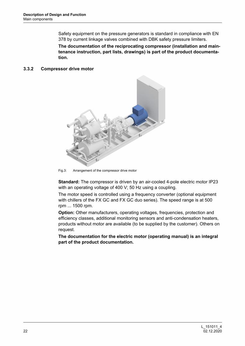
Fig.3: Arrangement of the compressor drive motor
Standard: The compressor is driven by an air-cooled 4-pole electric motor IP23with an operating voltage of 400 V; 50 Hz using a coupling.The motor speed is controlled using a frequency converter (optional equipmentwith chillers of the FX GC and FX GC duo series). The speed range is at 500rpm ... 1500 rpm.Option: Other manufacturers, operating voltages, frequencies, protection andefficiency classes, additional monitoring sensors and anti-condensation heaters,products without motor are available (to be supplied by the customer). Others onrequest.The documentation for the electric motor (operating manual) is an integralpart of the product documentation.
Description of Design and FunctionMain components
L_151011_422 02.12.2020
3.3.3 Coupling
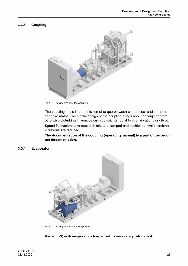
Fig.4: Arrangement of the coupling
The coupling helps in transmission of torque between compressor and compres-sor drive motor. The elastic design of the coupling brings about decoupling fromotherwise disturbing influences such as axial or radial forces, vibrations or offset.Speed fluctuations and speed shocks are damped and cushioned, while torsionalvibrations are reduced.The documentation of the coupling (operating manual) is a part of the prod-uct documentation.
3.3.4 Evaporator
Fig.5: Arrangement of the evaporator
Variant (W) with evaporator charged with a secondary refrigerant:
Description of Design and FunctionMain components
L_151011_4 02.12.2020 23

In the evaporator heat is absorbed from the secondary refrigerant (which isthereby cooled) by way of evaporation of the refrigerant.
Variant (K) with NH3 cascade evaporator:As a result of the evaporation of the refrigerant, heat is absorbed in the evapora-tor from the condensation of the refrigerant in the chiller circuit.
Liquid drops are effectively separated in the liquid separator integrated into theevaporator.Design, manufacture and acceptance of the evaporator with integrated liquid sep-arator comply with the requirements of the Pressure Equipment Directive.The documentation of the evaporator (operating and maintenance instruc-tions, acceptance certificate) is a part of the product documentation.
3.3.5 Condenser
Fig.6: Position of the condenser
In the condenser the compressed refrigerant vapour is desuperheated and lique-fied by dissipating the energy absorbed in the evaporator and compressor to theheat carrier (heating).Design, manufacture and acceptance of the condenser comply with the require-ments of the Pressure Equipment Directive.Condenser designed as a plate heat exchanger (included in the scope of deliv-ery)The documentation of the condenser (operating and maintenance instruc-tions, acceptance certificate) is a part of the product documentation.
Description of Design and FunctionMain components
L_151011_424 02.12.2020

3.3.6 Oil cooler
Fig.7: Arrangement of the oil cooler
The GEA RedGenium heat pumps are equipped with an air cooled oil cooler.The oil cooler is used for cooling the oil heated in the compressor in order toensure sufficient oil viscosity for supplying to the compressor.The documentation of the oil cooler (acceptance certificate) is part of theproduct documentation.
3.3.7 desuperheater (optional)
Fig.8: Position of the desuperheater
Description of Design and FunctionMain components
L_151011_4 02.12.2020 25

Depending on the specific project conditions, incorporating a desuperheater mayhave partly significant energy advantages and increase the efficiency of the heatpump, since the desuperheater capacity adds to the heating and cooling capacitywithout requiring additional drive power.Before condensing, the refrigerant is heated in the desuperheater by a certaintemperature difference (depending on the level of the heat carrier inlet and outlettemperatures), and its heat is transferred to the heat carrier.The documentation of the desuperheater (operating instructions, accept-ance certificate) is an integral part of the product documentation.
Description of Design and FunctionMain components
L_151011_426 02.12.2020

3.3.8 Subcooler (optional)
Fig.9: Position of the subcooler
Depending on the specific project conditions, incorporating a subcooler may havepartly significant energy advantages and increase the efficiency of the heatpump, since the subcooler capacity adds to the heating and cooling capacitywithout requiring additional drive power.After condensing, the refrigerant is supercooled in the subcooler by a certain tem-perature difference (depending on the level of the heat carrier inlet and outlettemperatures) and its heat is transferred to the heat carrier.The documentation of the subcooler (operating manual, acceptance certifi-cate) is part of the product documentation.
Description of Design and FunctionMain components
L_151011_4 02.12.2020 27

3.3.9 Control cabinet with control
Fig.10: Position of the control cabinet
The product is equipped with a GEA Omni™ control as standard.The switching cabinet and control device consists of the control with operatingand display unit, indicator lights for “Operation”, “Warning” and “Fault”, EMER-GENCY STOP button, coupling elements as well as the casing.For motors with an output power of up to 450 kW, the control cabinet with thecontrol is directly mounted on the product.For certain product series, the control cabinet can be optionally removed from thescope of delivery. In this case, only the GEA Omni™ control is mounted in a con-trol cabinet on the product.If the product operates with variable speed (standard for the GEA Blu chiller andGEA Red heat pump series), the frequency converter is integrated in the controlcabinet.
Notice
Depending on the motor size, the frequency converter (FC) must be instal-led in a separate cabinet. Depending on the application, the complete con-trol cabinet is mounted in a different configuration than the one shown, orthe FC cabinet is supplied separately.► Details can be found in the project-specific specifications or in the orderdrawings.
More details on the functional scope of the control can be found in the separatechapter concerning the GEA Omni™.
The documentation for the control (operating manual, circuit diagram,parameter list, communication guideline) is an integral part of the productdocumentation.
Description of Design and FunctionMain components
L_151011_428 02.12.2020

Notice
The communication guideline offers detailed information about communica-tion of the controller.► The communication guideline can be made available before a plannedinstallation.
3.3.10 FittingsThe term 'fittings' generally designates a control element of the product. Amongother things, the term 'fittings' is also used for valves if they are used for the con-trol and regulation of fluid flows in the pipes.Furthermore, all kinds of installations in pipes, such as sight glasses, measure-ment apertures, filters and similar, are also designated as fittings. Therefore, fit-tings also include all kinds of valves, such as
• Stop valves
• Check valves
• Safety valves
• Throttle valvesEach fitting has its own field of use, according to the pressure or temperature inthe pipe, the size of the pipe, the sealing requirements for the fitting, the reduc-tion and direction of the flow of liquid, as well as the medium itself.The safety fittings are used to limit the pressure in systems which are under pres-sure.Each fitting is designed for the specific application. The fittings can be operatedmanually or by motor, e.g. by gear motors, or pneumatic or hydraulic cylinders. Inreset fittings, the flow of fluid in the pipe causes automatic closing of the valve.Depending on the model, different closing elements (e.g. valve discs, flaps,washers) close the pipe connected to the fitting.The documentation of the fittings (acceptance certificate) forms part of theproduct documentation.
Description of Design and FunctionMain components
L_151011_4 02.12.2020 29

3.3.11 Safety devicesThe product is equipped with a comprehensive software safety chain preventingtoo high pressures, temperatures and the hazard of freezing.A suction as well as condenser pressure control and a rated current limitationcontrol cause a speed reduction whenever the adjustable limit values are excee-ded.Due to the applicable laws and regulations, various certifying bodies require avast range of auxiliary equipment with independent safety devices.Following safety equipment is included if the product is delivered with CE labelaccording to EN 378.
• Overflow valve (on the compressor) from discharge to suction side
• Double safety valve with pressure relief connection, installed on the low-pres-sure side of the product.
Notice
Proper installation of the pressure relief connection.► The contractors must guarantee that the pressure relief connection issafely operated to the outside.
• Safety pressure limiter via 2 switching positions with manual internal andexternal reset (one switching position may also be sufficient depending on theapplication)
• Pressure relief device for each closable container which can contain liquidrefrigerant.This applies to all containers with a diameter > 152 mm and a volume > 100litres barring oil separator and oil filter.
The scope of delivery does not include the following safety devices in relation toescaping ammonia:
• Protective equipment (health and industrial safety)
• Gas warning device/gas warning sensors (included as standard with the GEABluAir and GEA BluAir duo series)
In case of delivery according to EN 378 with CE label, all parts of the documenta-tion mentioned in the regulation are delivered in the national language of theplace where the chiller is installed.All other approvals have to be agreed upon separately.
3.3.12 Pressure limiting safety devicesThe pressure limiting safety devices of the product comply with EN 378-2.The overflow valve to protect the compressor is designed according to EN 13136.The blow-off pressure is set to the maximum permissible operating pressure ofthe system.The blow-off pipe has been dimensioned in accordance with EN 13136.The electro-mechanical safety switching devices for pressure limiting comply withEN12263 and are type-approved. The settings match the specifications of EN378-2.
Description of Design and FunctionMain components
L_151011_430 02.12.2020

If electronic safety switching devices are used for pressure limiting, the settingmay deviate from the standard specifications (see EN 378-2) due to theincreased precision.
Notice
When using safety valves for pressure relief, the operator is responsible for:► dimensioning of the piping,► safe discharge of refrigerant when the pressure relief device is triggered.
The safety devices for pressure limiting according to EN 378-2 are the minimumrequirements. Before commissioning, the requirements specified in the localoperational safety regulations must therefore be compared with those of EN378-2.The specified test intervals must be observed to ensure proper functioning of thesafety devices for pressure limiting. They are specified in the respective opera-tional safety regulations.
3.3.13 Components installed by the client
Warning!
GEA Refrigeration Germany GmbH does not assume any liability for arisingdamages or for the violation of the safety regulations resulting from the useof unsuitable materials or a modification to the product that is not included inthe original safety concept.► The material properties of components and system parts provided by andmonitored by the customer, in particular in the secondary refrigerant andheat carrier or coolant circuit as well as in the oil circuit, must be suitable forthe fluids flowing there. Furthermore, in the event of modifications to theproduct by the customer, the effects upon the safety devices must bechecked.
Description of Design and Function
L_151011_4 02.12.2020 31

4 GEA Omni™ control panel
4.1 Product HighlightsGEA stands for sophisticated high-precision solutions. With the new GEA Omni™control system, the system supplier demonstrates again its technological leader-ship and innovation.Powerful and practical, well thought out and intuitive, refined and simple – that isGEA Omni™.GEA Omni™ keeps what it promises: maximum efficiency and reliable operationof the system. The next generation control includes all important components of arefrigeration and gas compression system. This allows it a demand-driven andhighly efficient operation of the system.GEA Omni™ benefits at a glance:
• System control with only one devicecontrol of the refrigeration plant with GEA Omni™
• High-resolution display→ 1366 x 768 pixels
• Multi-touch display→ Ergonomic and intuitive input
• Easy integration→ Easy installation on site, ideal for retrofitting of existing systems
• Configurable Modbus TCP communication→ Data exchange with other systems without additional wiring
• Hardware design→ Standard industrial components with modular design
• Individual user profiles and management→ Set-up of individual user profiles and recording of user inputs
• Drawings, manuals and videos→ Technical documentation including helpful videos are available directly viathe touch panel
• Intelligent service intervals→ Timely notification of operating-specific maintenance recommendations
• GEA OmniLink™→ Application for remote control of the GEA Omni™ via Ethernet with integra-ted data transmission
• GEA OmniHistorian™→ Application for detailed analysis of recorded operating data histories
• Global product with local sales and service→ Globally available product in a uniform design
• Production in North America, Europe and Asia
GEA Omni™ control panelProduct Highlights
L_151011_432 02.12.2020

→ available in over 25 languages
• Reliability with GEA→ Developed, manufactured and supported by the market leader of controlsystems for refrigeration and gas compression systems
4.2 View
Fig.11: GEA Omni™ outer view without indicatorlights Fig.12: GEA Omni™ outer view with indicator lights
4.3 Standard functionThe GEA Omni™ supports the following standard functions:
• Display of all important physical and technical parameters, e.g. pressure, tem-perature, motor current, output, number of operating hours, operating modeand status signals.Various parameters and menus are hidden if they are not needed.
• Automatic start/stop of the product and capacity control depending on, forexample:
– Suction pressure
– Discharge pressure
– External pressure
– External temperature
– Network temperature
– Inlet temperature (evaporator, secondary refrigerant)
– Outlet temperature (evaporator, secondary refrigerant)
– Inlet temperature (condenser, cooling medium or heat carrier)
– Outlet temperature (condenser, cooling medium or heat carrier)
• Monitoring of all operating parameters.
GEA Omni™ control panelView
L_151011_4 02.12.2020 33

• Limited compressor capacity once any of the defined limit values is reachedor exceeded.
• Notification history (messages, warnings, and faults) with date and time.
• Wire failure detection for all analogue input signals.
• Password protection against unauthorised access to important parameters
• Storage of software, configuration and settings in non-volatile memory.
• Regulation by a superior control via potential-free contacts.
• Program stored non-volatile on a CFast card
• Possibility of communication with master control via Modbus TCP, Ethernet/IP(optionally via Profibus DP and ProfiNet)
• Remote access (optional via Ethernet)
4.4 Components of the GEA Omni™• Control cabinet (various sizes and installation options, see - IEC standard
IP54 / NEMA 4 minimum classification)
• Control cabinet with:
– Industrial PC with multi-touch screen and HD display for operation
– EMERGENCY STOP switch – directly connected to the control outputs, toimmediately switch off all rotating components
– USB port – with IP54 cover for data exchange with the industrial PC
– Optional indicator lights for:
® “Operation” – for status indicators start, operation or stop of the com-pressor
® “Warning” – for indication that an operating condition has exceeded thelimit for a warning
® “Fault” – for indication that the compressor is switched off
• Control cabinet interior view:
– Power supply for the industrial PC, input and output circuits and sensors
– Frequency inverter (optional)
– I/O system – as an interface for all digital and analogue inputs and control-led outputs
– Connections – for incoming power supply and cabling connections
– Fuses and circuit breakers – as short-circuit and overvoltage protection;industrial PC and I/O logic are protected by a fuse; the control and sensorpower supplies are protected by circuit breakers
– Cable ducts – as guide for the internal wiring
GEA Omni™ control panelComponents of the GEA Omni™
L_151011_434 02.12.2020

Fig.13: GEA Omni™ control cabinet interior view (frequency converter installed in the control cabinet)
GEA Omni™ control panelComponents of the GEA Omni™
L_151011_4 02.12.2020 35

4.5 Input and Output Signals
Low-voltage switchgear - GEA Omni™
from the low-voltage switchgear to the GEA Omni™INPUTS
from the GEA Omni™ to the low-voltage switchgearOUTPUTS
Not applicable if the low-voltage switchgear is included in the scope of supply.
Supply: 100 ... 240 V, 50/60 Hz digital • Motor feedback
• Motor protection compressor
digital • Run compressor
analogue(4-20 mA)
• Motor current compressor
• Compressor motor speed 5
analogue(4-20 mA)
• Compressor motor speed setpoint 5
Remote controller or BMS - GEA Omni™
from the remote controller (BMS) to the GEA Omni™INPUTS
from the GEA Omni™ to the remote controller (BMS)OUTPUTS
digital • External On/Off
• External "MORE"
• External "LESS"
• External motor start release
• External reset
• Changeover to 2nd setpoint
• Compressor blocked
digital • Ready for external mode signal
• Signal Compressor runs
• Main failure
• auxiliary output 1
analogue(4-20 mA)
• external setpoint
Refrigeration plant - GEA Omni™
from refrigeration plant to GEA Omni™INPUTS
from the GEA Omni™ to the refrigeration plantOUTPUTS
digital • External EMERGENCY STOP
• Separator level 6
• Gas sensor 6
digital: --
analogue(4-20 mA)
-- analogue(4-20 mA)
--
5 option, only for operation with frequency converter6 option
GEA Omni™ control panelInput and Output Signals
L_151011_436 02.12.2020

Chiller - GEA Omni™
from the chiller/heat pump to the GEA Omni™INPUTS
from GEA Omni™ to the chiller/heat pumpOUTPUTS
digital • Discharge pressure safety switch
• Refrigerant level up/down
digital • Solenoid valve capacity control 7
• Solenoid valve start-up unloading
analogue(4-20 mA)
• Suction pressure
• Discharge pressure
• Oil pressure
• Crankcase pressure
• Suction temperature
• Discharge temperature
• Oil temperature
analogue(4-20 mA)
• Setpoint IntelliSOC injection valve 6
• Setpoint level control 6
7 depending on the type of compressor
GEA Omni™ control panel
L_151011_4 02.12.2020 37

5 Technical data
5.1 Dimensions, weights and fill quantities
Fig.14: Connections GEA RedGenium (Variant (W))
5.1.1 GEA RedGenium 500 (W) ... GEA RedGenium 1100 (W) series
Notice
The data applies to the following standard conditions (application example 1pure heating mode, evaporator charged with external secondary refriger-ant):► Outlet temperature of secondary refrigerant +27 °C/+22 °C► Heat carrier temperature +50 °C/+70 °C
Data deviating from the standard can be the result of other conditions.
Characteristics
Code Parameter GEA RedGenium (W) heat pump
500 8 800 8 1100 8
Length 9 mm 4900 5300 5700
Width mm 1800 1800 2000
Height mm 2350 2400 2450
EConnectionCold water IN
DN 80 100 100
8 Values subject to technical changes9 plus frame protrusion (< 200 mm)
Technical dataDimensions, weights and fill quantities
L_151011_438 02.12.2020

Characteristics
Code Parameter GEA RedGenium (W) heat pump
500 8 800 8 1100 8
FConnectionCold water OUT
DN 80 100 100
G Connection 10
Heat carrier ONDN 80 80 100
H Connection 10
Heat carrier OFFDN 80 80 100
Connection of blow-off line to safetyvalve DN 25 25 25
Weight without charging kg 5500 6500 6960
Operating weight kg 5555 6565 7040
Filling quantity (Oil) l 20 27 38
Fill amount (refrigerant NH3) kg 35 40 45
8 Values subject to technical changes10 The position of the inlet/outlet connections of the heat carrier varies depending on the arrangement of the
heat exchanger (project-specific configuration)
Technical dataDimensions, weights and fill quantities
L_151011_4 02.12.2020 39
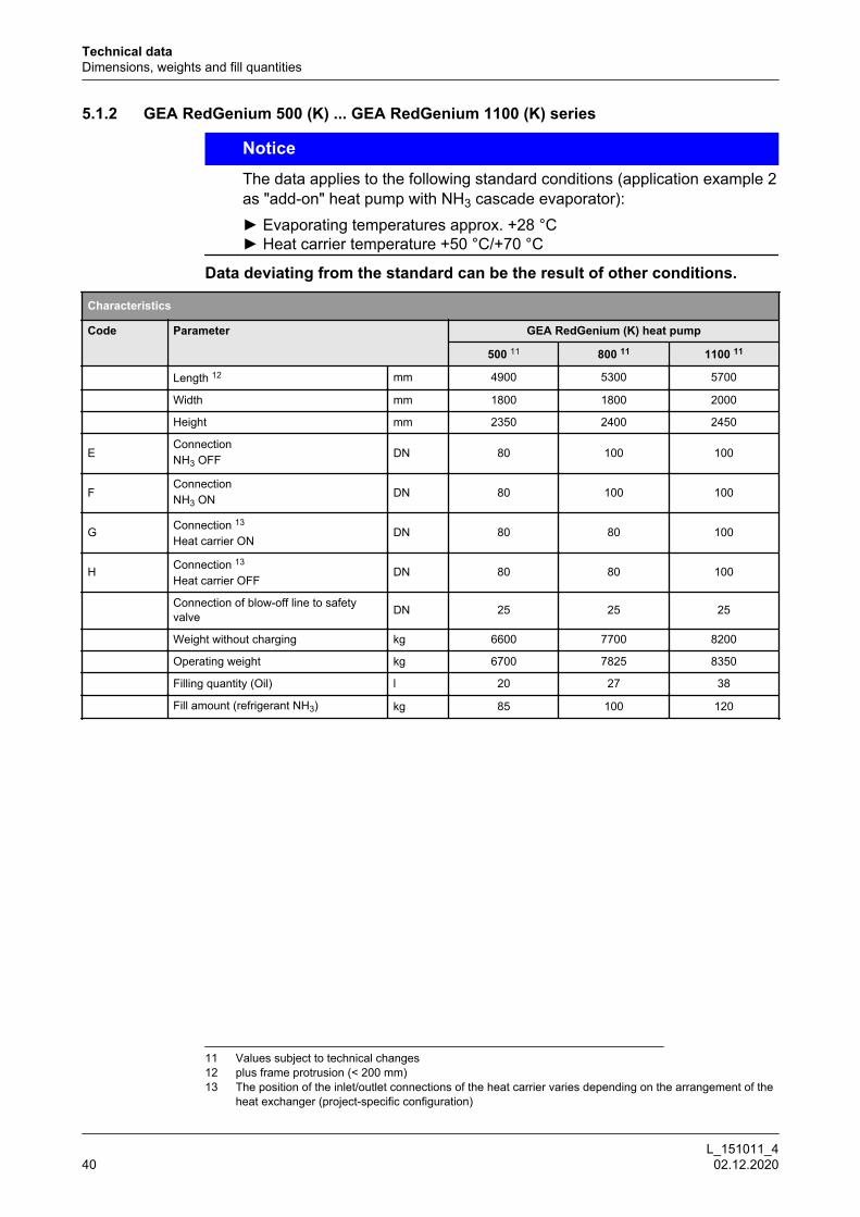
5.1.2 GEA RedGenium 500 (K) ... GEA RedGenium 1100 (K) series
Notice
The data applies to the following standard conditions (application example 2as "add-on" heat pump with NH3 cascade evaporator):► Evaporating temperatures approx. +28 °C► Heat carrier temperature +50 °C/+70 °C
Data deviating from the standard can be the result of other conditions.
Characteristics
Code Parameter GEA RedGenium (K) heat pump
500 11 800 11 1100 11
Length 12 mm 4900 5300 5700
Width mm 1800 1800 2000
Height mm 2350 2400 2450
EConnectionNH3 OFF DN 80 100 100
FConnectionNH3 ON DN 80 100 100
G Connection 13
Heat carrier ONDN 80 80 100
H Connection 13
Heat carrier OFFDN 80 80 100
Connection of blow-off line to safetyvalve DN 25 25 25
Weight without charging kg 6600 7700 8200
Operating weight kg 6700 7825 8350
Filling quantity (Oil) l 20 27 38
Fill amount (refrigerant NH3) kg 85 100 120
11 Values subject to technical changes12 plus frame protrusion (< 200 mm)13 The position of the inlet/outlet connections of the heat carrier varies depending on the arrangement of the
heat exchanger (project-specific configuration)
Technical dataDimensions, weights and fill quantities
L_151011_440 02.12.2020

5.2 Operation limitsThe heat pumps from the GEA RedGenium series can be operated within thespecified operation limits according to the respective specifications under diversework conditions. The operation limits listed below are based on the operationalprinciple of the reciprocating compressor, thermodynamic relationships, the ves-sels and safety devices in use, and the practical operating conditions.
Permissible minimum and maximum values for heat pumps of the GEA RedGenium series
Parameter GEA RedGenium
Speed n rpmmin 500
max 1500
Maximum permissible pressure, high pressure side PS bar(g) max 39
Maximum permissible pressure, low pressure side PS bar(g)min 16
max 25
Suction pressure psuc bar(g)min 2.0
max 13.0
Discharge pressure p bar(g) max 35
Pressure ratio p/psuc 14 π -min 1.5
max 6.0
Pressure difference p - psuc 14 Δp bar(g) max 25.0
Inlet temperature of secondary refrigerant 15 tK1 °Cmin +4.0
max +40.0
Outlet temperature of secondary refrigerant 15 tK2 °Cmin +3.0
max +35.0
Difference inlet / outlet temperature of secondaryrefrigerant 15 ΔtK K
min 1.0
max 10.0
Evaporating temperature NH3 cascade evaporator t0 °Cmin +10.0
max +34.0
Heating agent inlet temperature in the heat pump tW1 °Cmin +15.0
max +65.0
Heat carrier outlet temperature from heat pump 16 tW2 °Cmin +50.0
max +70.0
Difference inlet / outlet temperature of heat carrier ΔtK Kmin 5.0
max 50.0
14 The specified pressure ratio and pressure difference ensure reliable compressor operation. Furthermore,allowance must be made for the pressure difference necessary for the control valves fitted in the refriger-ating plant. Generalised maximum values for pressure ratio and difference cannot be specified due totheir dependence on different parameters. Depending on the suction pressure level, the maximum possi-ble discharge pressure may be below the value specified. The respective compressor usage diagramsapply. To comply with the minimum pressure difference, we recommend customer to provide a water-side3-way valve.
15 Minor inlet/outlet temperature differences up to 1 K of the secondary refrigerant may be implemented aslong as the max. permissible speed (7.5 m/s) is not exceeded at the heat-exchanger nozzle.
16 Depending on the temperature level of the secondary refrigerant and the corresponding suction pressure,the maximum possible outlet temperature of the heat carrier may be below the value specified due to themaximum pressure ratios and pressure differences. The respective temperature operation limit diagramsof the compressor apply. Higher outlet temperatures on request.
Technical dataOperation limits
L_151011_4 02.12.2020 41

Permissible minimum and maximum values for heat pumps of the GEA RedGenium series
Parameter GEA RedGenium
Oil temperature toil °Cmin +45
max +70
Discharge temperature at compressor outlet tdis °Cmin +80
max +150
Ambient temperature tU °Cmin +15
max +40
Relative ambient humidity 17 ƒ % max 95
Notes1. When considering a specific application, all the conditions specified in the
table must be taken into account and adhered to.
2. If the specified limits are exceeded for a specific application, GEA Refrigera-tion Germany GmbH must be consulted.
3. In addition to the operating limits stated in the tables, the applicable operatingconditions of the compressor must also be considered (e. g. start-up regime,oil pressure, oil quantity, oil type etc.).
4. The oil temperature at the compressor inlet must be at least 18 °C and below70 °C.
5. The specified data refer to the operating conditions of a heat pump.During downtime or start-up, the limiting values may be exceeded or fallenshort of for a short (never long-term) period of time.
6. The operating parameters of the order confirmation apply for an agreed fieldtest.
17 The max. permanent permissible ambient humidity depends on the drive motor and can be below 95%depending on the motor manufacturer and design. Binding values are detailed in the order specification.
Technical dataOperation limits
L_151011_442 02.12.2020

5.3 Water quality requirements, parametersAll water bearing components from the manufacturer give an optimum perform-ance and maximum protection from corrosion, if you meet all recommended limit-ing values of VDI 3803 issue 2010-02 (Tab. B3) for non-corrosive water and ade-quate water conditioning.
Notice
Disregarding the following rules for limiting values of non-corrosive waterspecified in VDI 3803, the manufacturer can not accept any warranty forwater-contacting components.► All components are designed for use with non-corrosive water. Waterand glycol brine analysis is essential in protecting system components.Analyses prior to start up will prevent corrosion.
Following are shown required limiting values of VDI 3803, for use of carbon steelcomponents in non corrosive water systems.
Water quality requirements, parameters
Parameter Value Unit
Appearance clear,without sediment
Colour colourless Odour none pH-level at 20 °C 7.5 - 9.0 Electrical conductivity LF < 220 mS/m
Soil alkali Ca2+, Mg2+ < 0.5 mol/m³
General hardness, for stabilization GH < 20 °d
Carbonate hardness without hardness sta-bilizer KH < 4 °d
Chloride Cl < 150 g/m³
Sulphur SO4 < 325 g/m³
Active biological components KBE < 10 000 per ml
Thickness factor EZ 2 - 4
The use of carbon steel and cast iron required in the most of applications waterconditioning with corrosion inhibitors.The use of stainless steel requires very special monitoring of water in apply toChloride contents (risk of stress crack and pitting corrosion).
Notice
Recommended with use of plate heat exchangers► < 100 ppm Cl for the use of 1.4301 and max. 40 °C wall temperature inthe plate heat exchanger► < 200 ppm Cl for the use of 1.4401 and max. 100 °C wall temperature inthe plate heat exchanger
Technical dataWater quality requirements, parameters
L_151011_4 02.12.2020 43

Fig.15: Corrosion resistance in presence of chlorides
X Chloride ion concentration in ppm Cl-
Y Wall temperature heat exchanger in °C
A AISI 304
B AISI 316
C SMO 254
Notice
Manufacturer recommendation: Use uncontaminated secondary refrigerantsand cooling media, in particular in chillers and the use of plate heatexchangers.► The media quality needs to be assured through an appropriate filter onthe inlet to the heat exchanger. The mesh for such a filter needs to be ≤ 0.9mm!► Should the chiller need to remain in operation during filter cleaning, dou-ble filters need to be used. Pressure loss through the filter need to be takeninto consideration on the building side when configuring the pump.
The manufacturer recommends enlisting the services of a reputable water condi-tioning company.
Technical dataWater quality requirements, parameters
L_151011_444 02.12.2020

5.4 Performance characteristics
5.4.1 GEA RedGenium 500 (W) … GEA RedGenium 1100 (W) series
Notice
The data applies to the following standard conditions(Application example 1 pure heating mode, evaporator charged with exter-nal secondary refrigerant):► Q0: Refrigerating capacity at cooling water inlet/outlet temperatures =27/22 °C► Pe: Drive power on mains (at 1500 rpm)► QH: Heating capacity at heat carrier inlet/outlet temperatures = 50/70 °C
Performance characteristics
Frame size Q0
in kWPe 18
in kWQH
in kW
GEA RedGenium 500 420 111 520
GEA RedGenium 800 640 167 790
GEA RedGenium 1100 840 218 1040
5.4.2 GEA RedGenium 500 (K) … GEA RedGenium 1100 (K) series
Notice
The data applies to the following standard conditions(Application example 2 as "add-on" heat pump with NH3 cascade evapora-tor):► Q0: Refrigerating capacity at evaporating temperatures of approx. 28 °C► Pe: Drive power on mains (at 1500 rpm)► QH: Heating capacity at heat carrier inlet/outlet temperatures = 50/70 °C
Performance characteristics
Frame size Q0
in kWPe 19
in kWQH
in kW
GEA RedGenium 500 555 116 660
GEA RedGenium 800 830 173 990
GEA RedGenium 1100 1105 226 1310
18 Clamping performance (including motor/frequency converter power losses)19 Clamping performance (including motor/frequency converter power losses)
Technical dataPerformance characteristics
L_151011_4 02.12.2020 45
6 Application formGEA Refrigeration Germany GmbH supplies products of high quality and reliabil-ity. With regard to project requirements, every product is configured, constructedand manufactured individually.Are you looking for the optimum solution for your application? Contact GEA salesand on request, we can provide you with an application form that you can alsoconveniently fill in and send away electronically.You can find an overview of sales offices and contacts at:www.gea.com
6.1 Manufacturer addressGEA Refrigeration Germany GmbH is a company of the GEA Group AG and pro-vides its customers around the world with high-quality components and servicesfor refrigeration and process technology applications.
Locations:
GEA Refrigeration Germany GmbHWerk BerlinHolzhauser Str. 16513509 Berlin, GermanyTel.: +49 30 43592-600Fax: +49 30 43592-777Web:www.gea.comE-Mail: [email protected]
GEA Refrigeration Germany GmbHWerk HalleBerliner Straße 13006258 Schkopau/ OT Döllnitz, GermanyTel.: +49 345 78 236 - 0Fax: +49 345 78 236 - 14Web:www.gea.comE-Mail: [email protected]
Application formManufacturer address
L_151011_446 02.12.2020

Application form
L_151011_4 02.12.2020 47
