geh-6721 vol i mark vie and mark vies control systems volume i · relateddocuments geh-6723...
TRANSCRIPT
GEH-6721_Vol_I_BN
Mark* VIe and Mark VIeS Control SystemsVolume I: System Guide
Dec 2019
Public Information

These instructions do not purport to cover all details or variations in equipment, nor to provide for every possiblecontingency to be met during installation, operation, and maintenance. The information is supplied for informationalpurposes only, and GE makes no warranty as to the accuracy of the information included herein. Changes, modifications,and/or improvements to equipment and specifications are made periodically and these changes may or may not be reflectedherein. It is understood that GE may make changes, modifications, or improvements to the equipment referenced herein or tothe document itself at any time. This document is intended for trained personnel familiar with the GE products referencedherein.
GE may have patents or pending patent applications covering subject matter in this document. The furnishing of thisdocument does not provide any license whatsoever to any of these patents.
Public Information – This document contains non-sensitive information approved for public disclosure.
GE provides the following document and the information included therein as is and without warranty of any kind,expressed or implied, including but not limited to any implied statutory warranty of merchantability or fitness forparticular purpose.
For further assistance or technical information, contact the nearest GE Sales or Service Office, or an authorized GE SalesRepresentative.
Revised: Dec 2019Issued: Jan 2004
© 2004 - 2019 General Electric Company.___________________________________* Indicates a trademark of General Electric Company and/or its subsidiaries.All other trademarks are the property of their respective owners.
We would appreciate your feedback about our documentation.Please send comments or suggestions to [email protected]
Public Information
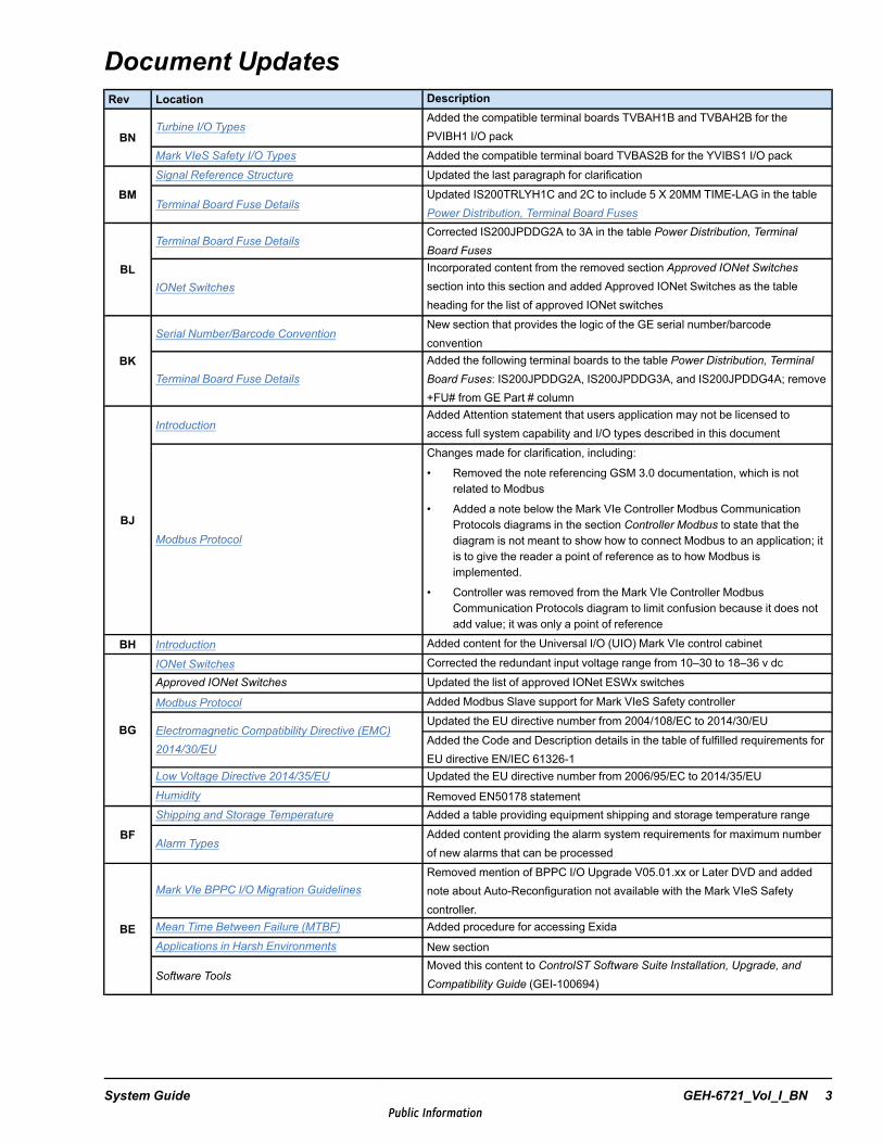
Document UpdatesRev Location Description
BNTurbine I/O Types
Added the compatible terminal boards TVBAH1B and TVBAH2B for thePVIBH1 I/O pack
Mark VIeS Safety I/O Types Added the compatible terminal board TVBAS2B for the YVIBS1 I/O pack
BMSignal Reference Structure Updated the last paragraph for clarification
Terminal Board Fuse DetailsUpdated IS200TRLYH1C and 2C to include 5 X 20MM TIME-LAG in the tablePower Distribution, Terminal Board Fuses
BL
Terminal Board Fuse DetailsCorrected IS200JPDDG2A to 3A in the table Power Distribution, TerminalBoard Fuses
IONet Switches
Incorporated content from the removed section Approved IONet Switchessection into this section and added Approved IONet Switches as the tableheading for the list of approved IONet switches
BK
Serial Number/Barcode ConventionNew section that provides the logic of the GE serial number/barcodeconvention
Terminal Board Fuse DetailsAdded the following terminal boards to the table Power Distribution, TerminalBoard Fuses: IS200JPDDG2A, IS200JPDDG3A, and IS200JPDDG4A; remove+FU# from GE Part # column
BJ
IntroductionAdded Attention statement that users application may not be licensed toaccess full system capability and I/O types described in this document
Modbus Protocol
Changes made for clarification, including:
• Removed the note referencing GSM 3.0 documentation, which is notrelated to Modbus
• Added a note below the Mark VIe Controller Modbus CommunicationProtocols diagrams in the section Controller Modbus to state that thediagram is not meant to show how to connect Modbus to an application; itis to give the reader a point of reference as to how Modbus isimplemented.
• Controller was removed from the Mark VIe Controller ModbusCommunication Protocols diagram to limit confusion because it does notadd value; it was only a point of reference
BH Introduction Added content for the Universal I/O (UIO) Mark VIe control cabinet
BG
IONet Switches Corrected the redundant input voltage range from 10–30 to 18–36 v dcApproved IONet Switches Updated the list of approved IONet ESWx switches
Modbus Protocol Added Modbus Slave support for Mark VIeS Safety controller
Electromagnetic Compatibility Directive (EMC)2014/30/EU
Updated the EU directive number from 2004/108/EC to 2014/30/EUAdded the Code and Description details in the table of fulfilled requirements forEU directive EN/IEC 61326-1
Low Voltage Directive 2014/35/EU Updated the EU directive number from 2006/95/EC to 2014/35/EUHumidity Removed EN50178 statement
BFShipping and Storage Temperature Added a table providing equipment shipping and storage temperature range
Alarm TypesAdded content providing the alarm system requirements for maximum numberof new alarms that can be processed
BE
Mark VIe BPPC I/O Migration GuidelinesRemoved mention of BPPC I/O Upgrade V05.01.xx or Later DVD and addednote about Auto-Reconfiguration not available with the Mark VIeS Safetycontroller.
Mean Time Between Failure (MTBF) Added procedure for accessing ExidaApplications in Harsh Environments New section
Software ToolsMoved this content to ControlST Software Suite Installation, Upgrade, andCompatibility Guide (GEI-100694)
System Guide GEH-6721_Vol_I_BN 3Public Information
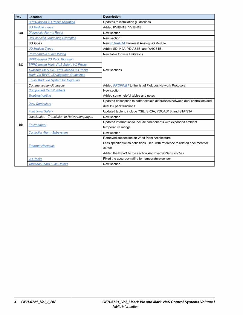
Rev Location Description
BD
BPPC-based I/O Packs Migration Updates to installation guideslinesI/O Module Types Added PVIBH1B, YVIBH1BDiagnostic Alarms Reset New sectionUnit-specific Grounding Examples New sectionI/O Types New PUAAH1A Universal Analog I/O Module
BC
I/O Module Types Added SDIIH2A, YDIAS1B, and YAICS1BPower and I/O Field Wiring New table for wire limitationsBPPC-based I/O Pack Migration
New sectionsBPPC-based Mark VIeS Safety I/O Packs
Available Mark VIe BPPC-based I/O PacksMark VIe BPPC I/O Migration Guidelines
Equip Mark VIe System for Migration
bb
Communication Protocols Added PROFINET to the list of Fieldbus Network ProtocolsComponent Part Numbers New sectionTroubleshooting Added some helpful tables and notes
Dual ControllersUpdated description to better explain differences between dual controllers anddual I/O pack functions.
Functional Safety Updated table to include YSIL, SRSA, YDOAS1B, and STAIS3ALocalization - Translation to Native Languages New section
EnvironmentUpdated information to include components with expanded ambienttemperature ratings
Controller Alarm Subsystem New section
Ethernet Networks
Removed subsection on Wind Plant ArchitectureLess specific switch definitions used, with reference to related document fordetailsAdded the ESWA to the section Approved IONet Switches
I/O Packs Fixed the accuracy rating for temperature sensorTerminal Board Fuse Details New section
4 GEH-6721_Vol_I_BN GEH-6721_Vol_I Mark VIe and Mark VIeS Control Systems Volume IPublic Information
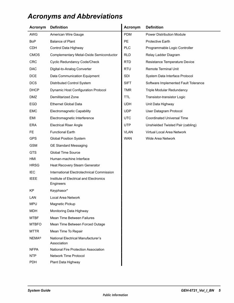
Acronyms and AbbreviationsAcronym Definition Acronym Definition
AWG American Wire Gauge PDM Power Distribution Module
BoP Balance of Plant PE Protective Earth
CDH Control Data Highway PLC Programmable Logic Controller
CMOS Complementary Metal-Oxide Semiconductor RLD Relay Ladder Diagram
CRC Cyclic Redundancy Code/Check RTD Resistance Temperature Device
DAC Digital-to-Analog Converter RTU Remote Terminal Unit
DCE Data Communication Equipment SDI System Data Interface Protocol
DCS Distributed Control System SIFT Software Implemented Fault Tolerance
DHCP Dynamic Host Configuration Protocol TMR Triple Modular Redundancy
DMZ Demilitarized Zone TTL Transistor-transistor Logic
EGD Ethernet Global Data UDH Unit Data Highway
EMC Electromagnetic Capability UDP User Datagram Protocol
EMI Electromagnetic Interference UTC Coordinated Universal Time
ERA Electrical Riser Angle UTP Unshielded Twisted Pair (cabling)
FE Functional Earth VLAN Virtual Local Area Network
GPS Global Position System WAN Wide Area Network
GSM GE Standard Messaging
GTS Global Time Source
HMI Human-machine Interface
HRSG Heat Recovery Steam Generator
IEC International Electrotechnical Commission
IEEE Institute of Electrical and ElectronicsEngineers
KP Keyphasor*
LAN Local Area Network
MPU Magnetic Pickup
MDH Monitoring Data Highway
MTBF Mean Time Between Failures
MTBFO Mean Time Between Forced Outage
MTTR Mean Time To Repair
NEMA® National Electrical Manufacturer’sAssociation
NFPA National Fire Protection Association
NTP Network Time Protocol
PDH Plant Data Highway
System Guide GEH-6721_Vol_I_BN 5Public Information

Related DocumentsGEH-6723 Mark VIeS Control Functional Safety Manual
GEH-6725 Mark VIe and Mark VIeS Control Systems Equipment in Hazardous Locations (HazLoc)Instruction Guide
GEH-6700 or GEH-6703 ToolboxST User Guide for Mark Controls Platform
GEH-6721_Vol_II Mark VIe and Mark VIeS Control Systems Volume II: System Guide for General-purposeApplications
GEH-6855_Vol_I Mark VIeS Functional Safety Systems for General Market Volume I: System Guide
GEH-6855_Vol_II Mark VIeS Functional Safety Systems for General Market Volume I: System Guide forGeneral-purpose Applications
GEH-6860 Mark VIeS Control General Market Functional Safety Manual
GEH-6861 Mark VIeS Functional Safety System Equipment in Hazardous Locations (HazLoc) InstructionGuide
GEH-6741 Sequential Function Chart Application Guide
GEH-6742 Mark VIe and Mark VIeS Virtual Controller User Guide
GEH-6757 WorkstationST GSM 3.0 User Guide
GEH-6760 WorkstationST GSM 3.0 Application Guide
GEH-6761 Mark VIe Control FOUNDATION Fieldbus™ Interface Application Guide
GEH-6812 Mark Controllers Shared IONet User Guide
GEI-100679 Mark VIe Distributed Control System (DCS) Block Library
GEI-100682 Mark VIe Control Standard Block Library
GEI-100681 Mark VIe Control Legacy Block Library
GEI-100694 ControlST Software Suite Installation, Upgrade, and Compatibility Guide
GEI-100795 Trender Instruction Guide
GEI-100620 WorkstationSTAlarm Viewer Instruction Guide
6 GEH-6721_Vol_I_BN GEH-6721_Vol_I Mark VIe and Mark VIeS Control Systems Volume IPublic Information
Safety Symbol Legend
Warning
Indicates a procedure or condition that, if not strictly observed, could result inpersonal injury or death.
Caution
Indicates a procedure or condition that, if not strictly observed, could result in damageto or destruction of equipment.
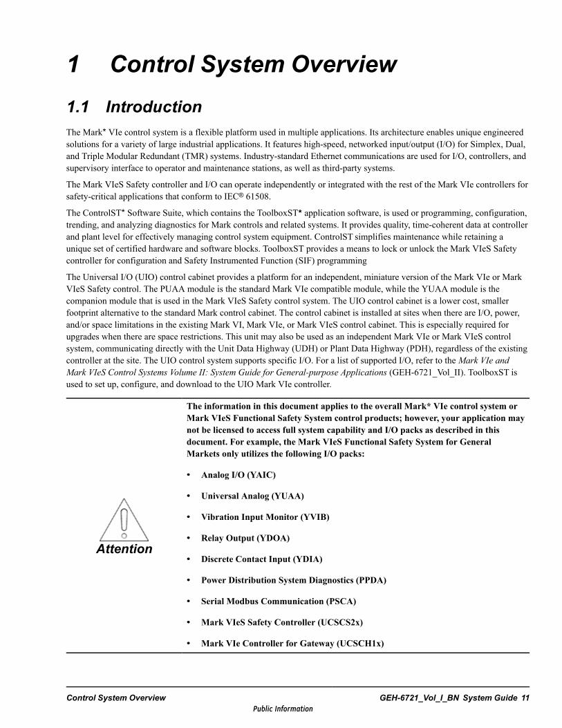
Attention
Indicates a procedure or condition that should be strictly followed to improve theseapplications.
GEH-6721_Vol_I_BN System Guide 7Public Information
Control System Warnings
Warning
To prevent personal injury or damage to equipment, follow all equipment safetyprocedures, Lockout Tagout (LOTO), and site safety procedures as indicated byEmployee Health and Safety (EHS) guidelines.
Warning
This equipment contains a potential hazard of electric shock, burn, or death. Onlypersonnel who are adequately trained and thoroughly familiar with the equipmentand the instructions should install, operate, or maintain this equipment.
Warning
Isolation of test equipment from the equipment under test presents potential electricalhazards. If the test equipment cannot be grounded to the equipment under test, thetest equipment’s case must be shielded to prevent contact by personnel.
To minimize hazard of electrical shock or burn, approved grounding practices andprocedures must be strictly followed.
Warning
To prevent personal injury or equipment damage caused by equipment malfunction,only adequately trained personnel should modify any programmable machine.
Warning
Always ensure that applicable standards and regulations are followed and onlyproperly certified equipment is used as a critical component of a safety system. Neverassume that the Human-machine Interface (HMI) or the operator will close a safetycritical control loop.
8 GEH-6721_Vol_I_BN GEH-6721_Vol_I Mark VIe and Mark VIeS Control Systems Volume IPublic Information
Contents1 Control System Overview............................................................................................................. 111.1 Introduction.......................................................................................................................................... 111.2 Controllers ........................................................................................................................................... 151.3 IONet Switches ..................................................................................................................................... 161.4 Distributed I/O Modules.......................................................................................................................... 161.5 Power Distribution................................................................................................................................. 361.6 Redundancy Options .............................................................................................................................. 371.7 Reliability and Availability ...................................................................................................................... 491.8 Component Part Numbers and Serial Numbers/Barcodes ............................................................................... 57
2 Functional Safety............................................................................................................................ 672.1 Safety Instrumented System (SIF)............................................................................................................. 682.2 Risk Reduction...................................................................................................................................... 692.3 Safety System Redundancy Options .......................................................................................................... 70
3 Ethernet Networks.......................................................................................................................... 753.1 Introduction.......................................................................................................................................... 753.2 IONet Layer ......................................................................................................................................... 803.3 Unit Control Layer................................................................................................................................. 863.4 Supervisory Layer.................................................................................................................................. 913.5 Monitoring Layer................................................................................................................................... 923.6 Enterprise Layer .................................................................................................................................... 933.7 Ethernet Cabling for Monitoring, Supervisory, and Unit Control Layers ........................................................... 943.8 Third-party Communication Links ............................................................................................................ 98
4 Communication Protocols ........................................................................................................... 994.1 OPC Protocols .....................................................................................................................................1014.2 WorkstationST GSM Protocol .................................................................................................................1044.3 Modbus Protocol ..................................................................................................................................1064.4 Ethernet Global Data (EGD) ...................................................................................................................1094.5 System Data Interface (SDI) Protocol .......................................................................................................1114.6 Network Time Protocol (NTP) ................................................................................................................1124.7 Fieldbus Communications ......................................................................................................................115
5 Technical Regulations, Standards, and Environment ........................................................ 1175.1 Safety Standards...................................................................................................................................1175.2 Conditions for Compliance .....................................................................................................................1185.3 Electrical.............................................................................................................................................1195.4 Environment ........................................................................................................................................121
6 Installation Guidelines ................................................................................................................1276.1 Installation Support ...............................................................................................................................1276.2 Equipment Receiving and Handling .........................................................................................................1306.3 Power Requirements .............................................................................................................................1326.4 Installation Support Drawings .................................................................................................................1346.5 Grounding...........................................................................................................................................1346.6 Cable Separation and Routing .................................................................................................................1436.7 Power and I/O Field Wiring ....................................................................................................................149
GEH-6721_Vol_I_BN System Guide 9Public Information
6.8 System Power Connection ......................................................................................................................1526.9 Startup Checks .....................................................................................................................................1536.10 BPPC-based I/O Pack Migration..............................................................................................................1586.11 Available Mark VIe BPPC-based I/O Packs ...............................................................................................1606.12 Mark VIe BPPC I/O Migration Guidelines.................................................................................................1616.13 Equip Mark VIe System for Migration ......................................................................................................163
7 Alarm Overview.............................................................................................................................1657.1 Alarm System Architecture.....................................................................................................................1657.2 Alarm Types ........................................................................................................................................1687.3 Controller Alarm Subsystem ...................................................................................................................1687.4 Diagnostic Alarms ................................................................................................................................1697.5 Process Alarms ....................................................................................................................................1727.6 Alarm Communication Flow...................................................................................................................174
8 Troubleshooting ...........................................................................................................................1758.1 Controller, I/O Pack, IONet Switch Not Powering On..................................................................................1758.2 Unable to Download to Controller............................................................................................................1788.3 Controller Not in Controlling State...........................................................................................................1798.4 Unable to Download to I/O Modules ........................................................................................................1848.5 Unable to Communicate with I/O Module .................................................................................................1858.6 Unable to Download to Controller or I/O Module .......................................................................................1868.7 Communication Loss Between Controller and I/O Module............................................................................1878.8 Boot Log Collection ..............................................................................................................................1888.9 I/O Module Replacement or Upgrade Issues...............................................................................................1898.10 LED Indicators.....................................................................................................................................194
Glossary of Terms ..............................................................................................................................195Index.......................................................................................................................................................199
10 GEH-6721_Vol_I_BN GEH-6721_Vol_I Mark VIe and Mark VIeS Control Systems Volume IPublic Information
1 Control System Overview1.1 IntroductionThe Mark* VIe control system is a flexible platform used in multiple applications. Its architecture enables unique engineeredsolutions for a variety of large industrial applications. It features high-speed, networked input/output (I/O) for Simplex, Dual,and Triple Modular Redundant (TMR) systems. Industry-standard Ethernet communications are used for I/O, controllers, andsupervisory interface to operator and maintenance stations, as well as third-party systems.
The Mark VIeS Safety controller and I/O can operate independently or integrated with the rest of the Mark VIe controllers forsafety-critical applications that conform to IEC® 61508.
The ControlST* Software Suite, which contains the ToolboxST* application software, is used or programming, configuration,trending, and analyzing diagnostics for Mark controls and related systems. It provides quality, time-coherent data at controllerand plant level for effectively managing control system equipment. ControlST simplifies maintenance while retaining aunique set of certified hardware and software blocks. ToolboxST provides a means to lock or unlock the Mark VIeS Safetycontroller for configuration and Safety Instrumented Function (SIF) programming
The Universal I/O (UIO) control cabinet provides a platform for an independent, miniature version of the Mark VIe or MarkVIeS Safety control. The PUAA module is the standard Mark VIe compatible module, while the YUAA module is thecompanion module that is used in the Mark VIeS Safety control system. The UIO control cabinet is a lower cost, smallerfootprint alternative to the standard Mark control cabinet. The control cabinet is installed at sites when there are I/O, power,and/or space limitations in the existing Mark VI, Mark VIe, or Mark VIeS control cabinet. This is especially required forupgrades when there are space restrictions. This unit may also be used as an independent Mark VIe or Mark VIeS controlsystem, communicating directly with the Unit Data Highway (UDH) or Plant Data Highway (PDH), regardless of the existingcontroller at the site. The UIO control system supports specific I/O. For a list of supported I/O, refer to theMark VIe andMark VIeS Control Systems Volume II: System Guide for General-purpose Applications (GEH-6721_Vol_II). ToolboxST isused to set up, configure, and download to the UIO Mark VIe controller.
Attention
The information in this document applies to the overall Mark* VIe control system orMark VIeS Functional Safety System control products; however, your application maynot be licensed to access full system capability and I/O packs as described in thisdocument. For example, the Mark VIeS Functional Safety System for GeneralMarkets only utilizes the following I/O packs:
•• Analog I/O (YAIC)
•• Universal Analog (YUAA)
•• Vibration Input Monitor (YVIB)
•• Relay Output (YDOA)
•• Discrete Contact Input (YDIA)
•• Power Distribution System Diagnostics (PPDA)
•• Serial Modbus Communication (PSCA)
•• Mark VIeS Safety Controller (UCSCS2x)
•• Mark VIe Controller for Gateway (UCSCH1x)
Control System Overview GEH-6721_Vol_I_BN System Guide 11Public Information
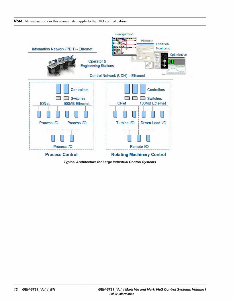
Note All instructions in this manual also apply to the UIO control cabinet.
Typical Architecture for Large Industrial Control Systems
12 GEH-6721_Vol_I_BN GEH-6721_Vol_I Mark VIe and Mark VIeS Control Systems Volume IPublic Information
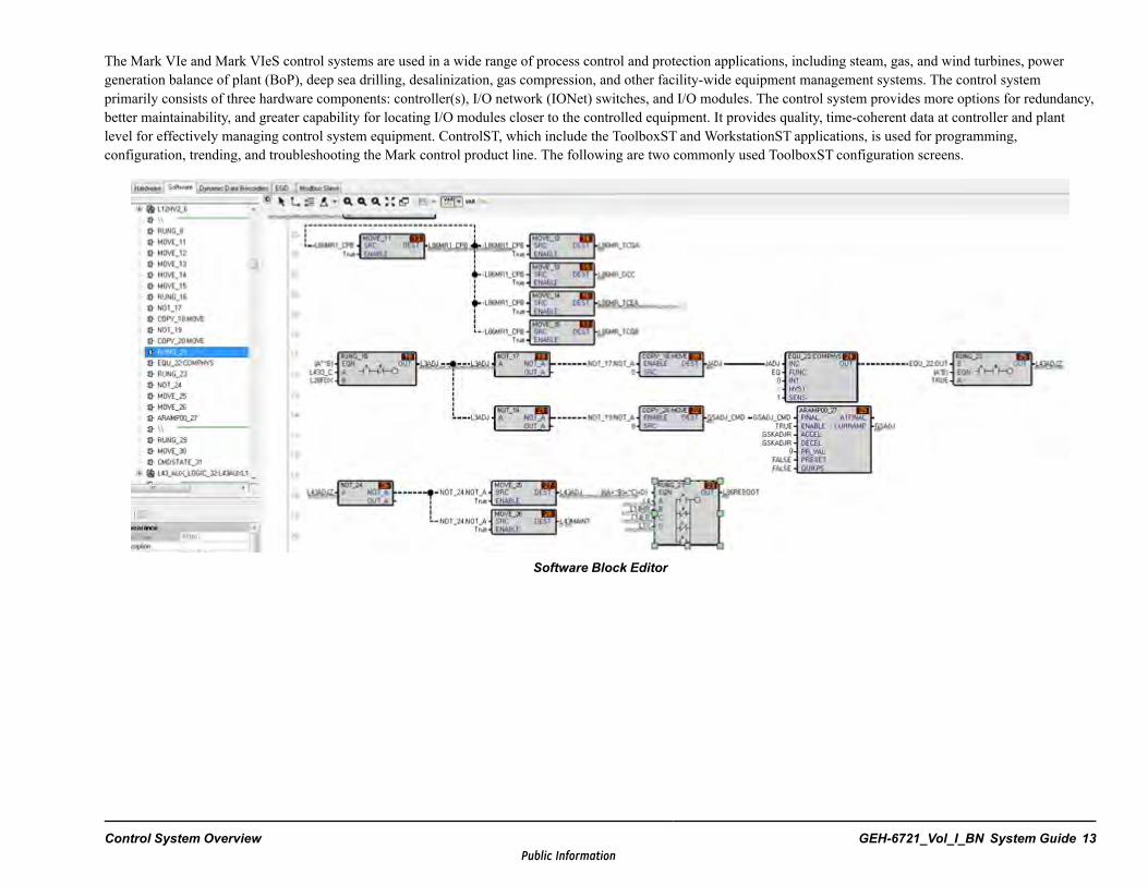
The Mark VIe and Mark VIeS control systems are used in a wide range of process control and protection applications, including steam, gas, and wind turbines, powergeneration balance of plant (BoP), deep sea drilling, desalinization, gas compression, and other facility-wide equipment management systems. The control systemprimarily consists of three hardware components: controller(s), I/O network (IONet) switches, and I/O modules. The control system provides more options for redundancy,better maintainability, and greater capability for locating I/O modules closer to the controlled equipment. It provides quality, time-coherent data at controller and plantlevel for effectively managing control system equipment. ControlST, which include the ToolboxST and WorkstationST applications, is used for programming,configuration, trending, and troubleshooting the Mark control product line. The following are two commonly used ToolboxST configuration screens.
Software Block Editor
Control System Overview GEH-6721_Vol_I_BN System Guide 13Public Information
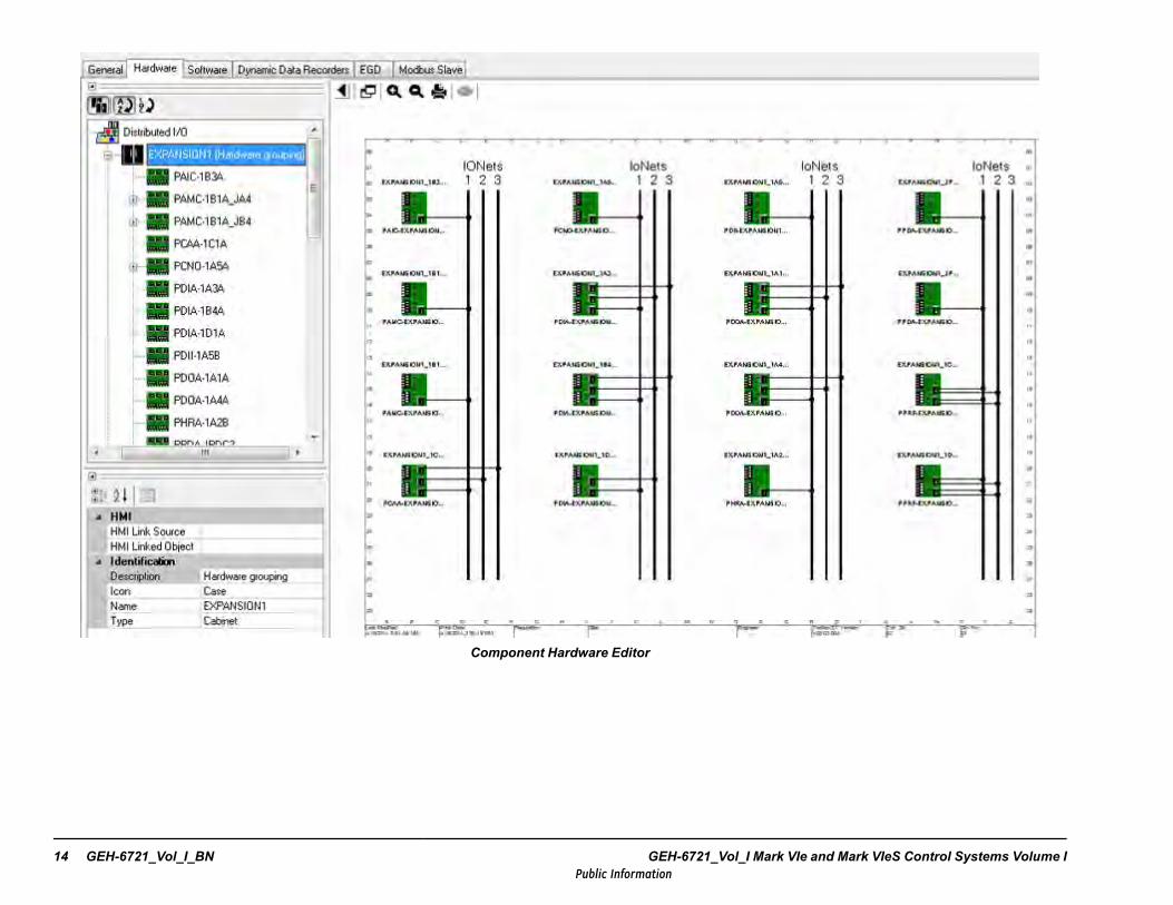
Component Hardware Editor
14 GEH-6721_Vol_I_BN GEH-6721_Vol_I Mark VIe and Mark VIeS Control Systems Volume IPublic Information
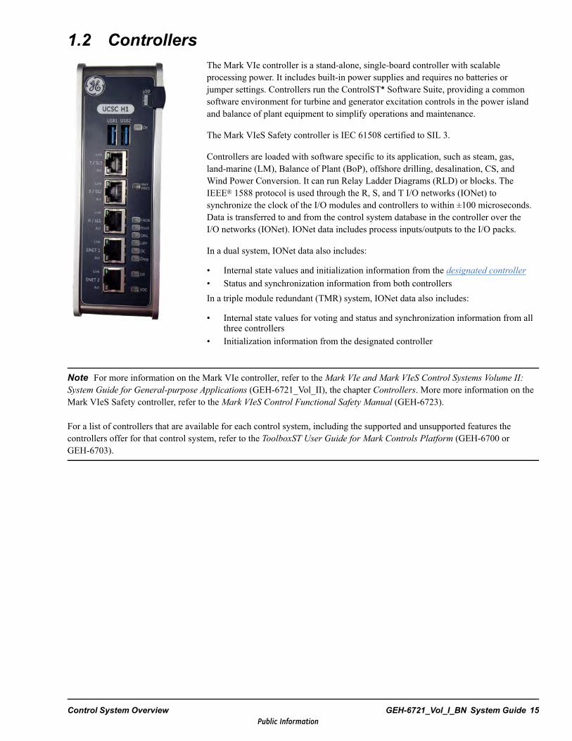
1.2 ControllersThe Mark VIe controller is a stand-alone, single-board controller with scalableprocessing power. It includes built-in power supplies and requires no batteries orjumper settings. Controllers run the ControlST* Software Suite, providing a commonsoftware environment for turbine and generator excitation controls in the power islandand balance of plant equipment to simplify operations and maintenance.
The Mark VIeS Safety controller is IEC 61508 certified to SIL 3.
Controllers are loaded with software specific to its application, such as steam, gas,land-marine (LM), Balance of Plant (BoP), offshore drilling, desalination, CS, andWind Power Conversion. It can run Relay Ladder Diagrams (RLD) or blocks. TheIEEE® 1588 protocol is used through the R, S, and T I/O networks (IONet) tosynchronize the clock of the I/O modules and controllers to within ±100 microseconds.Data is transferred to and from the control system database in the controller over theI/O networks (IONet). IONet data includes process inputs/outputs to the I/O packs.
In a dual system, IONet data also includes:
• Internal state values and initialization information from the designated controller• Status and synchronization information from both controllersIn a triple module redundant (TMR) system, IONet data also includes:
• Internal state values for voting and status and synchronization information from allthree controllers
• Initialization information from the designated controller
Note For more information on the Mark VIe controller, refer to the Mark VIe and Mark VIeS Control Systems Volume II:System Guide for General-purpose Applications (GEH-6721_Vol_II), the chapter Controllers. More more information on theMark VIeS Safety controller, refer to the Mark VIeS Control Functional Safety Manual (GEH-6723).
For a list of controllers that are available for each control system, including the supported and unsupported features thecontrollers offer for that control system, refer to the ToolboxST User Guide for Mark Controls Platform (GEH-6700 orGEH-6703).
Control System Overview GEH-6721_Vol_I_BN System Guide 15Public Information
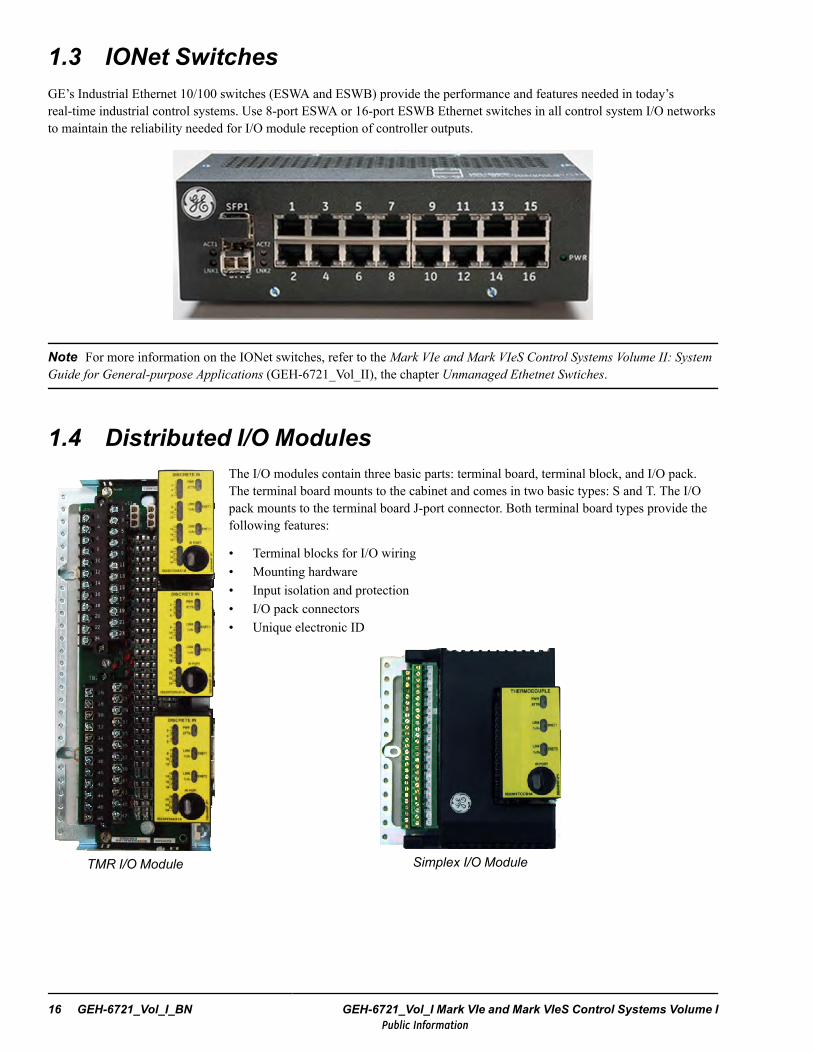
1.3 IONet SwitchesGE’s Industrial Ethernet 10/100 switches (ESWA and ESWB) provide the performance and features needed in today’sreal-time industrial control systems. Use 8-port ESWA or 16-port ESWB Ethernet switches in all control system I/O networksto maintain the reliability needed for I/O module reception of controller outputs.
Note For more information on the IONet switches, refer to the Mark VIe and Mark VIeS Control Systems Volume II: SystemGuide for General-purpose Applications (GEH-6721_Vol_II), the chapter Unmanaged Ethetnet Swtiches.
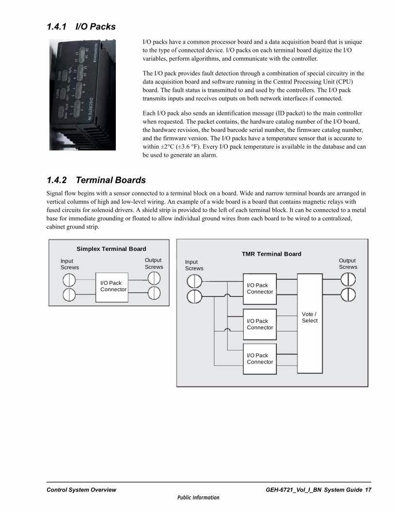
1.4 Distributed I/O Modules
TMR I/O Module
The I/O modules contain three basic parts: terminal board, terminal block, and I/O pack.The terminal board mounts to the cabinet and comes in two basic types: S and T. The I/Opack mounts to the terminal board J-port connector. Both terminal board types provide thefollowing features:
• Terminal blocks for I/O wiring• Mounting hardware• Input isolation and protection• I/O pack connectors• Unique electronic ID
Simplex I/O Module
16 GEH-6721_Vol_I_BN GEH-6721_Vol_I Mark VIe and Mark VIeS Control Systems Volume IPublic Information
1.4.1 I/O PacksI/O packs have a common processor board and a data acquisition board that is uniqueto the type of connected device. I/O packs on each terminal board digitize the I/Ovariables, perform algorithms, and communicate with the controller.
The I/O pack provides fault detection through a combination of special circuitry in thedata acquisition board and software running in the Central Processing Unit (CPU)board. The fault status is transmitted to and used by the controllers. The I/O packtransmits inputs and receives outputs on both network interfaces if connected.
Each I/O pack also sends an identification message (ID packet) to the main controllerwhen requested. The packet contains, the hardware catalog number of the I/O board,the hardware revision, the board barcode serial number, the firmware catalog number,and the firmware version. The I/O packs have a temperature sensor that is accurate towithin ±2°C (±3.6 °F). Every I/O pack temperature is available in the database and canbe used to generate an alarm.
1.4.2 Terminal BoardsSignal flow begins with a sensor connected to a terminal block on a board. Wide and narrow terminal boards are arranged invertical columns of high and low-level wiring. An example of a wide board is a board that contains magnetic relays withfused circuits for solenoid drivers. A shield strip is provided to the left of each terminal block. It can be connected to a metalbase for immediate grounding or floated to allow individual ground wires from each board to be wired to a centralized,cabinet ground strip.
Input Screws
I/O Pack Connector
Output Screws
Simplex Terminal Board
Input Screws
I/O Pack Connector
I/O Pack Connector
I/O Pack Connector
Output Screws
Vote / Select
TMR Terminal Board
Control System Overview GEH-6721_Vol_I_BN System Guide 17Public Information

1.4.2.1 T-typeT-type terminal boards typically fan the sensor inputs to three separate I/O packs. Usually, the TMR board hardware votes theoutputs from the three I/O packs. T-type boards contain two, 24-point, barrier-type, removable, terminal blocks. Each pointcan accept two 3.0 mm (0.12 in) (#12AWG) wires with 300 V insulation per point with either spade or ring-type lugs. Inaddition, captive clamps are provided for terminating bare wires. Screw spacing is 9.53 mm (0.375 in) minimum andcenter-to-center.
Note Some application-specific TMR terminal boards do not fan inputs or vote the outputs.
Barrier-type Terminal Blocks
These terminal blocks have the following features:
• Black in color with white number labels• Terminal rating is 300 V, 10 A• UL recognized• Recommended screw tightening torque is 7 lb-in (0.8 Nm).
18 GEH-6721_Vol_I_BN GEH-6721_Vol_I Mark VIe and Mark VIeS Control Systems Volume IPublic Information
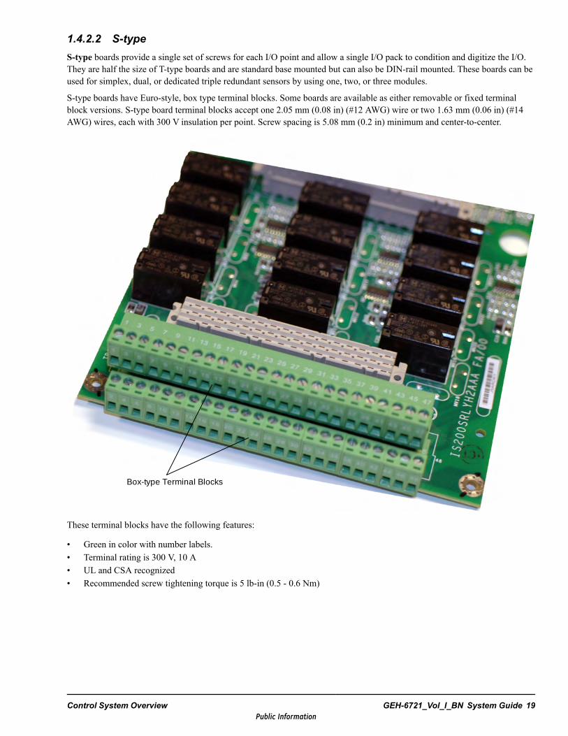
1.4.2.2 S-typeS-type boards provide a single set of screws for each I/O point and allow a single I/O pack to condition and digitize the I/O.They are half the size of T-type boards and are standard base mounted but can also be DIN-rail mounted. These boards can beused for simplex, dual, or dedicated triple redundant sensors by using one, two, or three modules.
S-type boards have Euro-style, box type terminal blocks. Some boards are available as either removable or fixed terminalblock versions. S-type board terminal blocks accept one 2.05 mm (0.08 in) (#12 AWG) wire or two 1.63 mm (0.06 in) (#14AWG) wires, each with 300 V insulation per point. Screw spacing is 5.08 mm (0.2 in) minimum and center-to-center.
Box-type Terminal Blocks
These terminal blocks have the following features:
• Green in color with number labels.• Terminal rating is 300 V, 10 A• UL and CSA recognized• Recommended screw tightening torque is 5 lb-in (0.5 - 0.6 Nm)
Control System Overview GEH-6721_Vol_I_BN System Guide 19Public Information
1.4.3 I/O Module Types
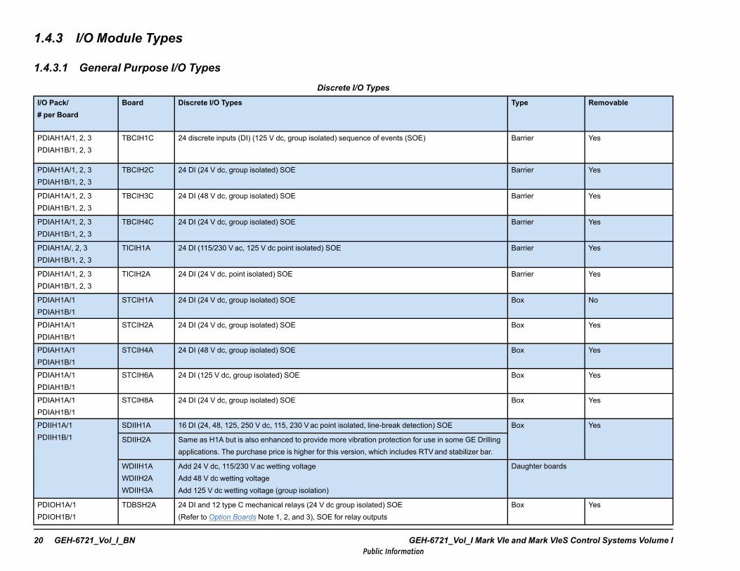
1.4.3.1 General Purpose I/O TypesDiscrete I/O Types
I/O Pack/# per Board
Board Discrete I/O Types Type Removable
PDIAH1A/1, 2, 3PDIAH1B/1, 2, 3
TBCIH1C 24 discrete inputs (DI) (125 V dc, group isolated) sequence of events (SOE) Barrier Yes
PDIAH1A/1, 2, 3PDIAH1B/1, 2, 3
TBCIH2C 24 DI (24 V dc, group isolated) SOE Barrier Yes
PDIAH1A/1, 2, 3PDIAH1B/1, 2, 3
TBCIH3C 24 DI (48 V dc, group isolated) SOE Barrier Yes
PDIAH1A/1, 2, 3PDIAH1B/1, 2, 3
TBCIH4C 24 DI (24 V dc, group isolated) SOE Barrier Yes
PDIAH1A/, 2, 3PDIAH1B/1, 2, 3
TICIH1A 24 DI (115/230 V ac, 125 V dc point isolated) SOE Barrier Yes
PDIAH1A/1, 2, 3PDIAH1B/1, 2, 3
TICIH2A 24 DI (24 V dc, point isolated) SOE Barrier Yes
PDIAH1A/1PDIAH1B/1
STCIH1A 24 DI (24 V dc, group isolated) SOE Box No
PDIAH1A/1PDIAH1B/1
STCIH2A 24 DI (24 V dc, group isolated) SOE Box Yes
PDIAH1A/1PDIAH1B/1
STCIH4A 24 DI (48 V dc, group isolated) SOE Box Yes
PDIAH1A/1PDIAH1B/1
STCIH6A 24 DI (125 V dc, group isolated) SOE Box Yes
PDIAH1A/1PDIAH1B/1
STCIH8A 24 DI (24 V dc, group isolated) SOE Box Yes
PDIIH1A/1PDIIH1B/1
SDIIH1A 16 DI (24, 48, 125, 250 V dc, 115, 230 Vac point isolated, line-break detection) SOE Box Yes
SDIIH2A Same as H1A but is also enhanced to provide more vibration protection for use in some GE Drillingapplications. The purchase price is higher for this version, which includes RTVand stabilizer bar.
WDIIH1AWDIIH2AWDIIH3A
Add 24 V dc, 115/230 Vac wetting voltageAdd 48 V dc wetting voltageAdd 125 V dc wetting voltage (group isolation)
Daughter boards
PDIOH1A/1PDIOH1B/1
TDBSH2A 24 DI and 12 type C mechanical relays (24 V dc group isolated) SOE(Refer to Option Boards Note 1, 2, and 3), SOE for relay outputs
Box Yes
20 GEH-6721_Vol_I_BN GEH-6721_Vol_I Mark VIe and Mark VIeS Control Systems Volume IPublic Information
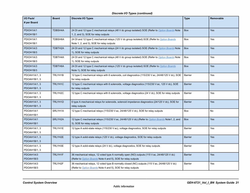
Discrete I/O Types (continued)
I/O Pack/# per Board
Board Discrete I/O Types Type Removable
PDIOH1A/1PDIOH1B/1
TDBSH4A 24 DI and 12 type C mechanical relays (48 V dc group isolated) SOE (Refer to Option Boards Note1, 2, and 3), SOE for relay outputs
Box Yes
PDIOH1A/1PDIOH1B/1
TDBSH6A 24 DI and 12 type C mechanical relays (125 V dc group isolated) SOE (Refer to Option BoardsNote 1, 2, and 3), SOE for relay outputs
Box Yes
PDIOH1A/3PDIOH1B/3
TDBTH2A 24 DI and 12 type C mechanical relays (24 V dc group isolated) SOE (Refer to Option Boards Note1), SOE for relay outputs
Box Yes
PDIOH1A/3PDIOH1B/3
TDBTH4A 24 DI and 12 type C mechanical relays (48 V dc group isolated) SOE (Refer to Option Boards Note1), SOE for relay outputs
Box Yes
PDIOH1A/3PDIOH1B/3
TDBTH6A 24 DI and 12 type C mechanical relays (125 V dc group isolated) SOE (Refer to Option BoardsNote 1), SOE for relay outputs
Box Yes
PDOAH1A/1, 3PDOAH1B/1, 3
TRLYH1B 12 type C mechanical relays with 6 solenoids, coil diagnostics (115/230 V ac, 24/48/125 V dc), SOEfor relay outputs
Barrier Yes
PDOAH1A/1, 3PDOAH1B/1, 3
TRLYH1C 12 type C mechanical relays with 6 solenoids, voltage diagnostics (115/230 V ac, 125 V dc), SOEfor relay outputs
Barrier Yes
PDOAH1A/1, 3PDOAH1B/1, 3
TRLYH2C 12 type C mechanical relays with 6 solenoids, voltage diagnostics (24 V dc), SOE for relay outputs Barrier Yes
PDOAH1A/1, 3PDOAH1B/1, 3
TRLYH1D 6 type A mechanical relays for solenoids, solenoid impedance diagnostics (24/125 V dc), SOE forrelay outputs
Barrier Yes
PDOAH1A/1PDOAH1B/1
SRLYH1A 12 type C mechanical relays (115/230 Vac, 24/48/125 V dc), SOE for relay outputs Box No
PDOAH1A/1PDOAH1B/1
SRLYH2A 12 type C mechanical relays (115/230 Vac, 24/48/125 V dc) (Refer to Option Boards Note1, 2, and3), SOE for relay outputs
Box Yes
PDOAH1A/1, 3PDOAH1B/1, 3
TRLYH1E 12 type A solid-state relays (115/230 V ac), voltage diagnostics, SOE for relay outputs Barrier Yes
PDOAH1A/1, 3PDOAH1B/1, 3
TRLYH2E 12 type A solid-state relays (125 V dc), voltage diagnostics, SOE for relay outputs Barrier Yes
PDOAH1A/1, 3PDOAH1B/1, 3
TRLYH3E 12 type A solid-state relays (24 V dc), voltage diagnostics, SOE for relay outputs Barrier Yes
PDOAH1A/3PDOAH1B/3
TRLYH1F 36 mechanical relays, 12 voted type A normally open (NO) outputs (115 V ac, 24/48/125 V dc)(Refer to Option Boards Note 4 and 5), SOE for relay outputs
Barrier Yes
PDOAH1A/3PDOAH1B/3
TRLYH2F 36 mechanical relays, 12 voted type B normally closed (NC) outputs (115 V ac, 24/48/125 V dc)(Refer to Option Boards Note 4 and 5), SOE for relay outputs
Barrier Yes
Control System Overview GEH-6721_Vol_I_BN System Guide 21Public Information
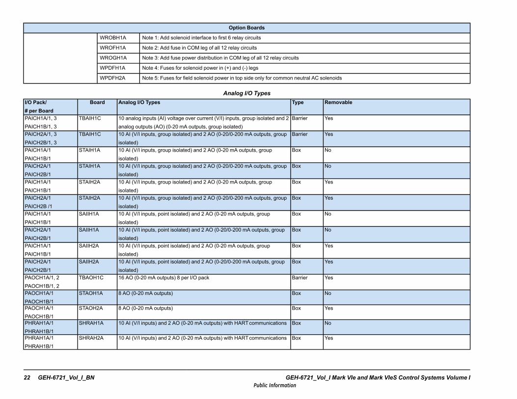
Option Boards
WROBH1A Note 1: Add solenoid interface to first 6 relay circuits
WROFH1A Note 2: Add fuse in COM leg of all 12 relay circuits
WROGH1A Note 3: Add fuse power distribution in COM leg of all 12 relay circuits
WPDFH1A Note 4: Fuses for solenoid power in (+) and (-) legs
WPDFH2A Note 5: Fuses for field solenoid power in top side only for common neutral AC solenoids
Analog I/O TypesI/O Pack/# per Board
Board Analog I/O Types Type Removable
PAICH1A/1, 3PAICH1B/1, 3
TBAIH1C 10 analog inputs (AI) voltage over current (V/I) inputs, group isolated and 2analog outputs (AO) (0-20 mA outputs, group isolated)
Barrier Yes
PAICH2A/1, 3PAICH2B/1, 3
TBAIH1C 10 AI (V/I inputs, group isolated) and 2 AO (0-20/0-200 mA outputs, groupisolated)
Barrier Yes
PAICH1A/1PAICH1B/1
STAIH1A 10 AI (V/I inputs, group isolated) and 2 AO (0-20 mA outputs, groupisolated)
Box No
PAICH2A/1PAICH2B/1
STAIH1A 10 AI (V/I inputs, group isolated) and 2 AO (0-20/0-200 mA outputs, groupisolated)
Box No
PAICH1A/1PAICH1B/1
STAIH2A 10 AI (V/I inputs, group isolated) and 2 AO (0-20 mA outputs, groupisolated)
Box Yes
PAICH2A/1PAICH2B /1
STAIH2A 10 AI (V/I inputs, group isolated) and 2 AO (0-20/0-200 mA outputs, groupisolated)
Box Yes
PAICH1A/1PAICH1B/1
SAIIH1A 10 AI (V/I inputs, point isolated) and 2 AO (0-20 mA outputs, groupisolated)
Box No
PAICH2A/1PAICH2B/1
SAIIH1A 10 AI (V/I inputs, point isolated) and 2 AO (0-20/0-200 mA outputs, groupisolated)
Box No
PAICH1A/1PAICH1B/1
SAIIH2A 10 AI (V/I inputs, point isolated) and 2 AO (0-20 mA outputs, groupisolated)
Box Yes
PAICH2A/1PAICH2B/1
SAIIH2A 10 AI (V/I inputs, point isolated) and 2 AO (0-20/0-200 mA outputs, groupisolated)
Box Yes
PAOCH1A/1, 2PAOCH1B/1, 2
TBAOH1C 16 AO (0-20 mA outputs) 8 per I/O pack Barrier Yes
PAOCH1A/1PAOCH1B/1
STAOH1A 8 AO (0-20 mA outputs) Box No
PAOCH1A/1PAOCH1B/1
STAOH2A 8 AO (0-20 mA outputs) Box Yes
PHRAH1A/1PHRAH1B/1
SHRAH1A 10 AI (V/I inputs) and 2 AO (0-20 mA outputs) with HARTcommunications Box No
PHRAH1A/1PHRAH1B/1
SHRAH2A 10 AI (V/I inputs) and 2 AO (0-20 mA outputs) with HARTcommunications Box Yes
22 GEH-6721_Vol_I_BN GEH-6721_Vol_I Mark VIe and Mark VIeS Control Systems Volume IPublic Information
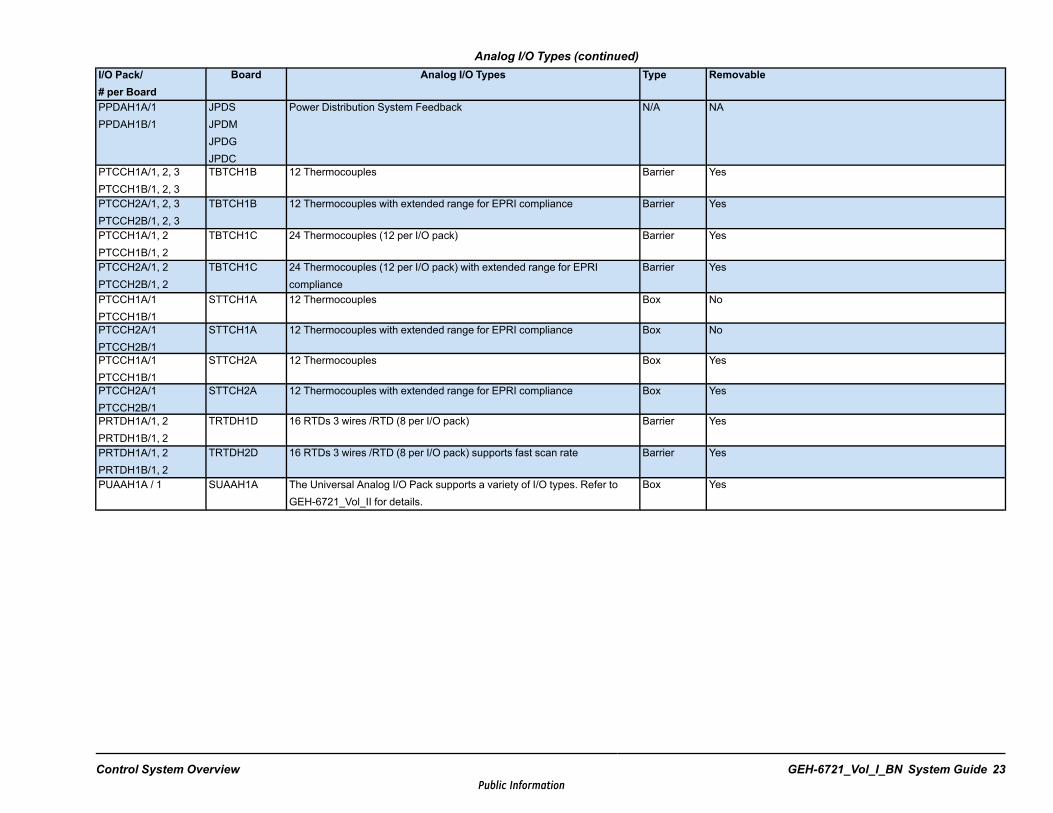
Analog I/O Types (continued)I/O Pack/# per Board
Board Analog I/O Types Type Removable
PPDAH1A/1PPDAH1B/1
JPDSJPDMJPDGJPDC
Power Distribution System Feedback N/A NA
PTCCH1A/1, 2, 3PTCCH1B/1, 2, 3
TBTCH1B 12 Thermocouples Barrier Yes
PTCCH2A/1, 2, 3PTCCH2B/1, 2, 3
TBTCH1B 12 Thermocouples with extended range for EPRI compliance Barrier Yes
PTCCH1A/1, 2PTCCH1B/1, 2
TBTCH1C 24 Thermocouples (12 per I/O pack) Barrier Yes
PTCCH2A/1, 2PTCCH2B/1, 2
TBTCH1C 24 Thermocouples (12 per I/O pack) with extended range for EPRIcompliance
Barrier Yes
PTCCH1A/1PTCCH1B/1
STTCH1A 12 Thermocouples Box No
PTCCH2A/1PTCCH2B/1
STTCH1A 12 Thermocouples with extended range for EPRI compliance Box No
PTCCH1A/1PTCCH1B/1
STTCH2A 12 Thermocouples Box Yes
PTCCH2A/1PTCCH2B/1
STTCH2A 12 Thermocouples with extended range for EPRI compliance Box Yes
PRTDH1A/1, 2PRTDH1B/1, 2
TRTDH1D 16 RTDs 3 wires /RTD (8 per I/O pack) Barrier Yes
PRTDH1A/1, 2PRTDH1B/1, 2
TRTDH2D 16 RTDs 3 wires /RTD (8 per I/O pack) supports fast scan rate Barrier Yes
PUAAH1A / 1 SUAAH1A The Universal Analog I/O Pack supports a variety of I/O types. Refer toGEH-6721_Vol_II for details.
Box Yes
Control System Overview GEH-6721_Vol_I_BN System Guide 23Public Information

1.4.3.2 Fieldbus I/O Types
I/O Pack/Qty per Board
Board Communications Types Type Removable
PSCHHIA/1, 2 SSCAH1ASSCAH2A
6 serial6 serial
BoxBox
NoYes
PSCAH1A/1PSCAH1B/1
SSCAH1A 6 MODBUS Master serial or 1 Modbus Ethernet Box No
PSCAH1A/1PSCAH1B/1
SSCAH2A 6 MODBUS Master serial or 1 Modbus Ethernet Box Yes
PCNOH1A/1PCNOH1B/1
SPIDG1A CANopen Master Gateway N/A N/A
PPRFH1A/1PPRFH1B/1
PROFIBUS - DP-V0, Class 1 Master CommunicationsPROFIBUS - DP-V1 Class 1 Master Communications(PPRFH1B only)
N/A N/A
PPNGH1A N/A PROFINET RT Version 2.2 I/O gateway module mapsI/O from PROFINETslave devices to the Mark VIecontroller on the IONet
N/A N/A
PFFAH1A/1 N/A FOUNDATION Fieldbus H1 TO HSE Linking Device N/A N/A
24 GEH-6721_Vol_I_BN GEH-6721_Vol_I Mark VIe and Mark VIeS Control Systems Volume IPublic Information
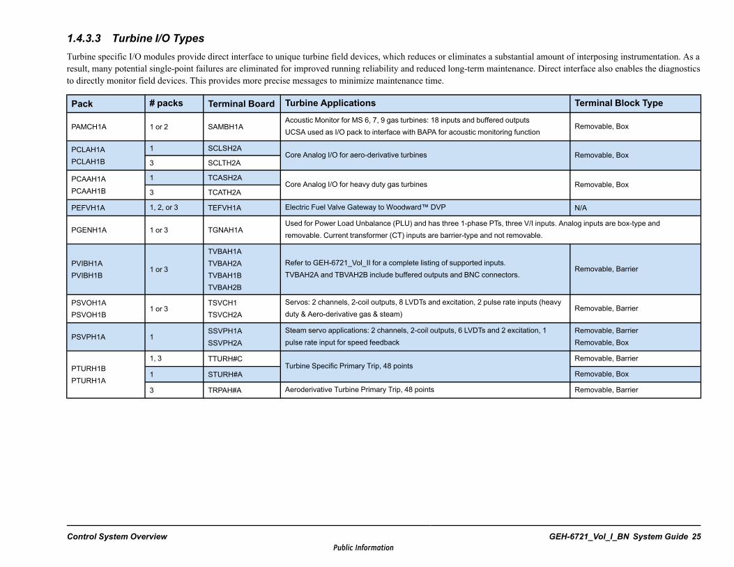
1.4.3.3 Turbine I/O TypesTurbine specific I/O modules provide direct interface to unique turbine field devices, which reduces or eliminates a substantial amount of interposing instrumentation. As aresult, many potential single-point failures are eliminated for improved running reliability and reduced long-term maintenance. Direct interface also enables the diagnosticsto directly monitor field devices. This provides more precise messages to minimize maintenance time.
Pack # packs Terminal Board Turbine Applications Terminal Block Type
PAMCH1A 1 or 2 SAMBH1AAcoustic Monitor for MS 6, 7, 9 gas turbines: 18 inputs and buffered outputsUCSA used as I/O pack to interface with BAPA for acoustic monitoring function
Removable, Box
PCLAH1APCLAH1B
1 SCLSH2ACore Analog I/O for aero-derivative turbines Removable, Box
3 SCLTH2A
PCAAH1APCAAH1B
1 TCASH2ACore Analog I/O for heavy duty gas turbines Removable, Box
3 TCATH2A
PEFVH1A 1, 2, or 3 TEFVH1A Electric Fuel Valve Gateway to Woodward™ DVP N/A
PGENH1A 1 or 3 TGNAH1AUsed for Power Load Unbalance (PLU) and has three 1-phase PTs, three V/I inputs. Analog inputs are box-type andremovable. Current transformer (CT) inputs are barrier-type and not removable.
PVIBH1APVIBH1B
1 or 3
TVBAH1ATVBAH2ATVBAH1BTVBAH2B
Refer to GEH-6721_Vol_II for a complete listing of supported inputs.TVBAH2A and TBVAH2B include buffered outputs and BNC connectors.
Removable, Barrier
PSVOH1APSVOH1B
1 or 3TSVCH1TSVCH2A
Servos: 2 channels, 2-coil outputs, 8 LVDTs and excitation, 2 pulse rate inputs (heavyduty & Aero-derivative gas & steam)
Removable, Barrier
PSVPH1A 1SSVPH1ASSVPH2A
Steam servo applications: 2 channels, 2-coil outputs, 6 LVDTs and 2 excitation, 1pulse rate input for speed feedback
Removable, BarrierRemovable, Box
PTURH1BPTURH1A
1, 3 TTURH#CTurbine Specific Primary Trip, 48 points
Removable, Barrier
1 STURH#A Removable, Box
3 TRPAH#A Aeroderivative Turbine Primary Trip, 48 points Removable, Barrier
Control System Overview GEH-6721_Vol_I_BN System Guide 25Public Information

Pack # packs TerminalBoard
Turbine Applications Terminal Block Type
PPRAS1B††
PPRAS1A††3
TREAS#A +WREAS1A Aero-derivative Turbine Emergency Trip, 48
pointsTREA_1A: Removable, BarrierTREA_3A: Removable, Box
PPRAH1A 3TREAH#A +WREAH1A
PPROS1B†† 3 TPROS#C Backup Turbine Protection, 48 points TPRO_1A: Removable, BarrierTPRO_2A: Removable, Box
PPROS1BPPROH1A
3 TPROH#C
1 SPROH#A Backup Turbine Protection, 24 pointsSPROH1A: Removable, BarrierSPROH2A: Removable, Box
3 TREAH#AAero-derivative Turbine Emergency Trip, 48points
H1A, H2A: Removable, BarrierH3A, H4A: Removable, Box
††These modules have IEC 61508 safety-certified functions
26 GEH-6721_Vol_I_BN GEH-6721_Vol_I Mark VIe and Mark VIeS Control Systems Volume IPublic Information

1.4.3.4 Migration I/O TypesThe following table provides a list of I/O modules approved for use with Mark V, Mark V LM, and Mark VI migration to the Mark VIe control
Mark V, Mark V LM, and Mark VI Migration to Mark VIe Control
I/O Pack/Qtyper Board
TerminalBoard
InterfaceBoard
Migration I/O Types Type Removable
PIOAH1A/1 N/A JPDV Mark VARCNET I/O (for excitation control) N/A N/A
PMVE/1, 3
QTBATBQATBQBTBQCTBQFTBQDTBQGCTBATBCATBCB
TCQCMVRAMVRBMVRCMVRF
UCSA used as I/O pack controller to interface withdedicated Mark V turbine I/O application boards.
Box
No – H1A,Yes - H2A,No - G1A,No - G1B
PMVD/1, 3
DTBADTBBDTBCDTBD
TCRA96 contact inputs,60 relay contact outputs
Box
No – H1A,Yes – H2A,No –G1A,No – G1B
PMVP/3PTBAG1APTBAG2A
Expansionboard TCEBand tripboards TCTE,TCTG, TCTL,TCTS,
2 magnetic p.u. speed inputs,8 flame detector pulse inputs,Trip solenoid interface relays,Generator breaker synchronizing circuitsE-Stop
Barrier No
PCMI VRID
Any existingMark VI VMEboard exceptVPYR, VSCA,VPRO, orVAMB
Migration from Mark VI Master Interface N/A N/A
Control System Overview GEH-6721_Vol_I_BN System Guide 27Public Information
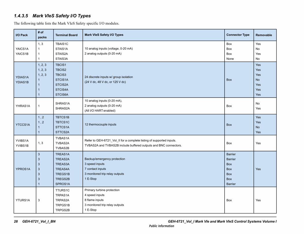
1.4.3.5 Mark VIeS Safety I/O TypesThe following table lists the Mark VIeS Safety specific I/O modules.
I/O Pack# ofpacks
Terminal Board Mark VIeS Safety I/O Types Connector Type Removable
YAICS1AYAICS1B
1, 3111
TBAIS1CSTAIS1ASTAIS2ASTAIS3A
10 analog inputs (voltage, 0-20 mA)2 analog outputs (0-20 mA)
BoxBoxBoxNone
YesNoYesNo
YDIAS1AYDIAS1B
1, 2, 31, 2, 31, 2, 31111
TBCIS1TBCIS2TBCIS3STCIS1ASTCIS2ASTCIS4ASTCIS6A
24 discrete inputs w/ group isolation(24 V dc, 48 V dc, or 125 V dc)
Box
YesYesYesNoYesYesYes
YHRAS1A 1SHRAS1ASHRAS2A
10 analog inputs (0-20 mA),2 analog outputs (0-20 mA)(All I/O HARTenabled)
BoxNoYes
YTCCS1A
1 , 21 , 211
TBTCS1BTBTCS1CSTTCS1ASTTCS2A
12 thermocouple inputs Box
YesYesNoYes
YVIBS1AYVIBS1B
1, 3TVBAS1ATVBAS2ATVBAS2B
Refer to GEH-6721_Vol_II for a complete listing of supported inputs.TVBAS2A and TVBAS2B include buffered outputs and BNC connectors.
Box Yes
YPROS1A
3333331
TREAS1ATREAS2ATREAS3ATREAS4ATREGS1BTREGS2BSPROS1A
Backup/emergency protection3 speed inputs7 contact inputs3 monitored trip relay outputs1 E-Stop
BarrierBarrierBoxBoxBoxBoxBarrier
Yes
YTURS1A 3
TTURS1CTRPAS1ATRPAS2ATRPGS1BTRPGS2B
Primary turbine protection4 speed inputs8 flame inputs3 monitored trip relay outputs1 E-Stop
Box Yes
28 GEH-6721_Vol_I_BN GEH-6721_Vol_I Mark VIe and Mark VIeS Control Systems Volume IPublic Information
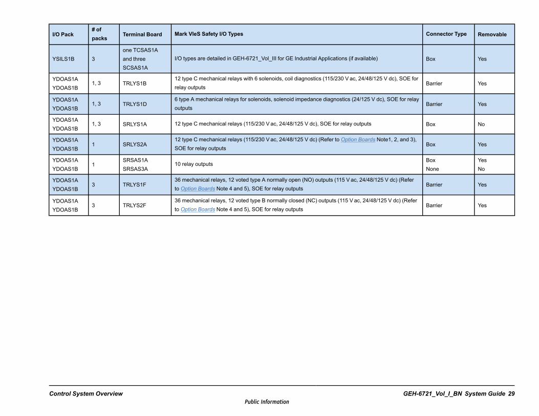
I/O Pack# ofpacks
Terminal Board Mark VIeS Safety I/O Types Connector Type Removable
YSILS1B 3one TCSAS1Aand threeSCSAS1A
I/O types are detailed in GEH-6721_Vol_III for GE Industrial Applications (if available) Box Yes
YDOAS1AYDOAS1B
1, 3 TRLYS1B12 type C mechanical relays with 6 solenoids, coil diagnostics (115/230 V ac, 24/48/125 V dc), SOE forrelay outputs
Barrier Yes
YDOAS1AYDOAS1B
1, 3 TRLYS1D6 type A mechanical relays for solenoids, solenoid impedance diagnostics (24/125 V dc), SOE for relayoutputs
Barrier Yes
YDOAS1AYDOAS1B
1, 3 SRLYS1A 12 type C mechanical relays (115/230 Vac, 24/48/125 V dc), SOE for relay outputs Box No
YDOAS1AYDOAS1B
1 SRLYS2A12 type C mechanical relays (115/230 Vac, 24/48/125 V dc) (Refer to Option Boards Note1, 2, and 3),SOE for relay outputs
Box Yes
YDOAS1AYDOAS1B
1SRSAS1ASRSAS3A
10 relay outputsBoxNone
YesNo
YDOAS1AYDOAS1B
3 TRLYS1F36 mechanical relays, 12 voted type A normally open (NO) outputs (115 V ac, 24/48/125 V dc) (Referto Option Boards Note 4 and 5), SOE for relay outputs
Barrier Yes
YDOAS1AYDOAS1B
3 TRLYS2F36 mechanical relays, 12 voted type B normally closed (NC) outputs (115 V ac, 24/48/125 V dc) (Referto Option Boards Note 4 and 5), SOE for relay outputs
Barrier Yes
Control System Overview GEH-6721_Vol_I_BN System Guide 29Public Information

1.4.3.6 Renewable Energy I/O TypesThe following table lists the Renewable Energy I/O types.
Assembly Individual Boards Renewable I/O Types
AEPAH1AAEPAH1ABPPB Alternative Energy Pitch Axis, special-purpose in 1.5 MW wind pitch control: 8 analog inputs, 1 incremental encoder input, 1 absolute
encoder input, 1 analog output, 20 discrete inputs, 1 discrete output, 8 relay outputs, 2 RS-485 interfaces, 1 brake control outputAEPAH1C
AEPAH1ABPPC
AEPCH1AAEPCH1ABPPB
Alternative Energy Pitch Center module in 20, 30, and 40 Newton Meters (Nm) wind pitch control: 1 24 V dc, 8 A power input, 1 RS-422interface
AEPCH1BAEPCH1BBPPB
AEPCH1CAEPCH1CBPPB
AEPCH1DAEPCH1ABPPCWEMDH4
AEPCH1EAEPCH1BBPPCWEMDH5
AEPCH1FAEPCH1CBPPC
WEPAH1AAEPAH1BBPPBWPCI
Wind Energy Pitch Axis special-purpose in 30 and 40 Nm wind pitch control: 8 analog inputs, 1 incremental encoder input, 1 analogoutput, 20 discrete inputs, 2 discrete outputs, 9 relay outputs, 2 RS-485 interfaces, 2 PWM control outputs
WEPAH1BAEPAH1BBPPCWPCI
WEPAH2AAEPAH1BBPPB
WEPAH2BAEPAH1BBPPC
WETAH1AWETAH1ABPPB
Wind Energy Top Box board A, special-purpose in 1.5 MW ESS turbine: 69 digital inputs; 8 are pulse-rate counter inputs, 18 analog PT100temperature sensor inputs, 2 analog thermistor temperature sensor inputs, 12 analog 4 to 20 mA current inputs, 25 relay contact outputs19 solid-state relay outputs, 1 RS-485 interfaceWETAH1B
WETAH1BBPPC
WCBMH1A WCBMH1AWind Condition Top Box Monitor condition-based monitoring for wind turbines, measures vibration on main bearing, gearbox, andgenerator bearings
WEMAH1AWEMABPPB Wind Energy Main converter control for ESS wind turbine: 27 digital inputs, 2 analog thermistor temperature sensor inputs, 9 relay contact
outputs, 3 solid-state relay outputsWEMAH1B
WEMABPPC
30 GEH-6721_Vol_I_BN GEH-6721_Vol_I Mark VIe and Mark VIeS Control Systems Volume IPublic Information
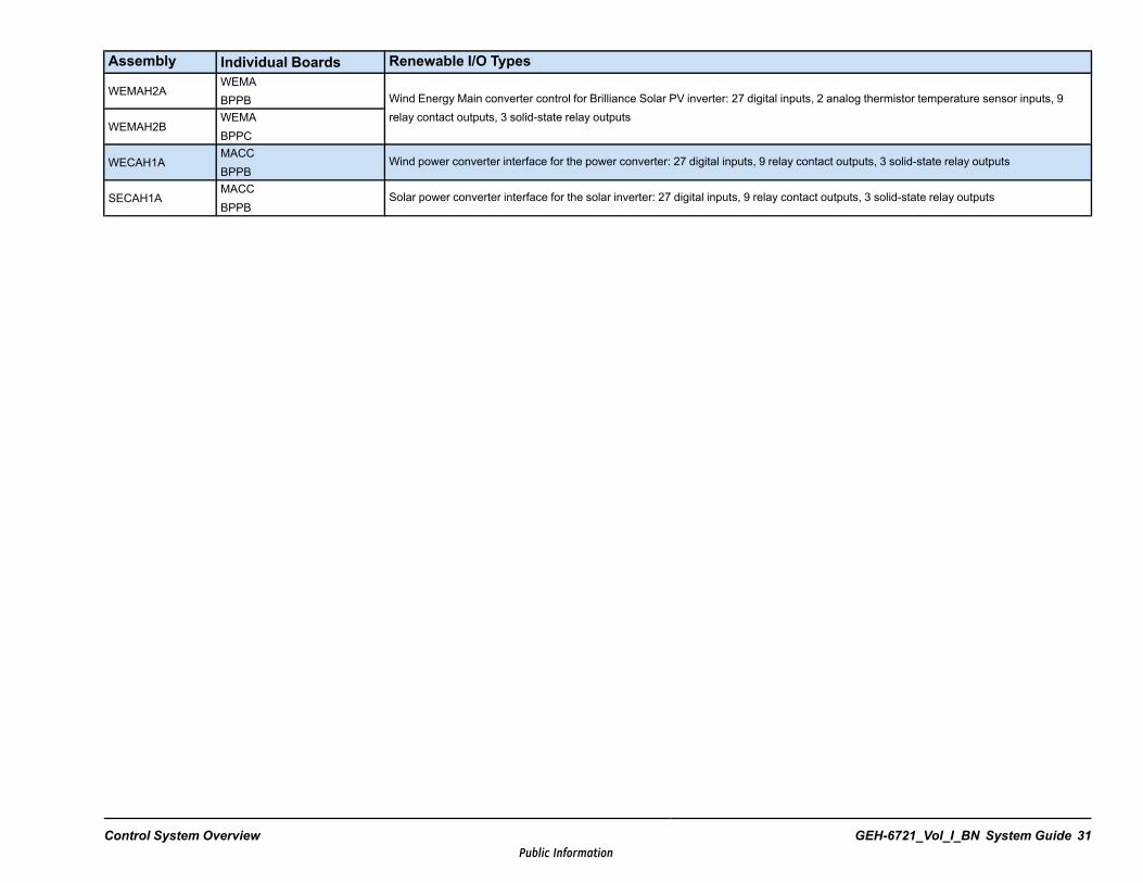
Assembly Individual Boards Renewable I/O Types
WEMAH2AWEMABPPB Wind Energy Main converter control for Brilliance Solar PV inverter: 27 digital inputs, 2 analog thermistor temperature sensor inputs, 9
relay contact outputs, 3 solid-state relay outputsWEMAH2B
WEMABPPC
WECAH1AMACCBPPB
Wind power converter interface for the power converter: 27 digital inputs, 9 relay contact outputs, 3 solid-state relay outputs
SECAH1AMACCBPPB
Solar power converter interface for the solar inverter: 27 digital inputs, 9 relay contact outputs, 3 solid-state relay outputs
Control System Overview GEH-6721_Vol_I_BN System Guide 31Public Information
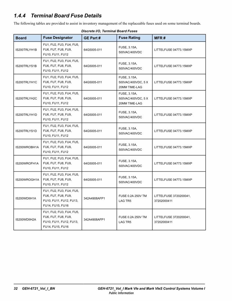
1.4.4 Terminal Board Fuse DetailsThe following tables are provided to assist in inventory management of the replaceable fuses used on some terminal boards.
Discrete I/O, Terminal Board Fuses
Board Fuse Designator GE Part # Fuse Rating MFR #
IS200TRLYH1BFU1, FU2, FU3, FU4, FU5,FU6, FU7, FU8, FU9,FU10, FU11, FU12
64G5005-011FUSE, 3.15A,500VAC/400VDC
LITTELFUSE 04773.15MXP
IS200TRLYS1BFU1, FU2, FU3, FU4, FU5,FU6, FU7, FU8, FU9,FU10, FU11, FU12
64G5005-011FUSE, 3.15A,500VAC/400VDC
LITTELFUSE 04773.15MXP
IS200TRLYH1CFU1, FU2, FU3, FU4, FU5,FU6, FU7, FU8, FU9,FU10, FU11, FU12
64G5005-011FUSE, 3.15A,500VAC/400VDC, 5 X20MM TIME-LAG
LITTELFUSE 04773.15MXP
IS200TRLYH2CFU1, FU2, FU3, FU4, FU5,FU6, FU7, FU8, FU9,FU10, FU11, FU12
64G5005-011FUSE, 3.15A,500VAC/400VDC, 5 X20MM TIME-LAG
LITTELFUSE 04773.15MXP
IS200TRLYH1DFU1, FU2, FU3, FU4, FU5,FU6, FU7, FU8, FU9,FU10, FU11, FU12
64G5005-011FUSE, 3.15A,500VAC/400VDC
LITTELFUSE 04773.15MXP
IS200TRLYS1DFU1, FU2, FU3, FU4, FU5,FU6, FU7, FU8, FU9,FU10, FU11, FU12
64G5005-011FUSE, 3.15A,500VAC/400VDC
LITTELFUSE 04773.15MXP
IS200WROBH1AFU1, FU2, FU3, FU4, FU5,FU6, FU7, FU8, FU9,FU10, FU11, FU12
64G5005-011FUSE, 3.15A,500VAC/400VDC
LITTELFUSE 04773.15MXP
IS200WROFH1AFU1, FU2, FU3, FU4, FU5,FU6, FU7, FU8, FU9,FU10, FU11, FU12
64G5005-011FUSE, 3.15A,500VAC/400VDC
LITTELFUSE 04773.15MXP
IS200WROGH1AFU1, FU2, FU3, FU4, FU5,FU6, FU7, FU8, FU9,FU10, FU11, FU12
64G5005-011FUSE, 3.15A,500VAC/400VDC
LITTELFUSE 04773.15MXP
IS200WDIIH1A
FU1, FU2, FU3, FU4, FU5,FU6, FU7, FU8, FU9,FU10, FU11, FU12, FU13,FU14, FU15, FU16
342A4908AFP1FUSE 0.2A 250V TMLAG TR5
LITTELFUSE 3720200041,37202000411
IS200WDIIH2A
FU1, FU2, FU3, FU4, FU5,FU6, FU7, FU8, FU9,FU10, FU11, FU12, FU13,FU14, FU15, FU16
342A4908AFP1FUSE 0.2A 250V TMLAG TR5
LITTELFUSE 3720200041,37202000411
32 GEH-6721_Vol_I_BN GEH-6721_Vol_I Mark VIe and Mark VIeS Control Systems Volume IPublic Information
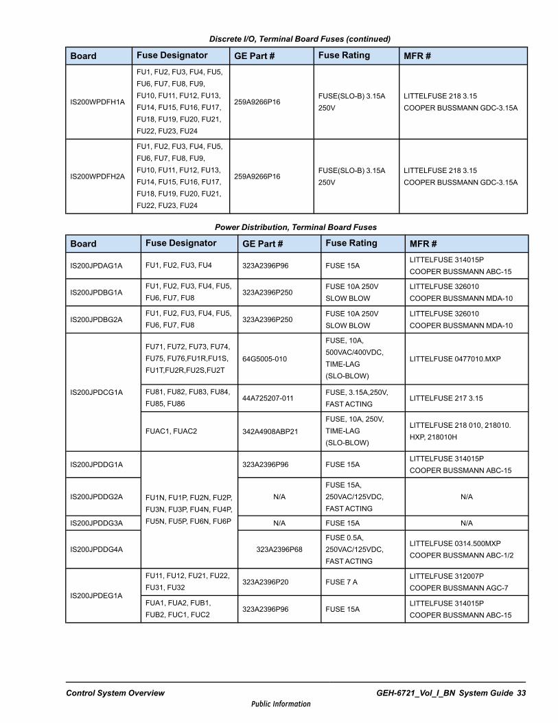
Discrete I/O, Terminal Board Fuses (continued)
Board Fuse Designator GE Part # Fuse Rating MFR #
IS200WPDFH1A
FU1, FU2, FU3, FU4, FU5,FU6, FU7, FU8, FU9,FU10, FU11, FU12, FU13,FU14, FU15, FU16, FU17,FU18, FU19, FU20, FU21,FU22, FU23, FU24
259A9266P16FUSE(SLO-B) 3.15A250V
LITTELFUSE 218 3.15COOPER BUSSMANN GDC-3.15A
IS200WPDFH2A
FU1, FU2, FU3, FU4, FU5,FU6, FU7, FU8, FU9,FU10, FU11, FU12, FU13,FU14, FU15, FU16, FU17,FU18, FU19, FU20, FU21,FU22, FU23, FU24
259A9266P16FUSE(SLO-B) 3.15A250V
LITTELFUSE 218 3.15COOPER BUSSMANN GDC-3.15A
Power Distribution, Terminal Board Fuses
Board Fuse Designator GE Part # Fuse Rating MFR #
IS200JPDAG1A FU1, FU2, FU3, FU4 323A2396P96 FUSE 15ALITTELFUSE 314015PCOOPER BUSSMANN ABC-15
IS200JPDBG1AFU1, FU2, FU3, FU4, FU5,FU6, FU7, FU8
323A2396P250FUSE 10A 250VSLOW BLOW
LITTELFUSE 326010COOPER BUSSMANN MDA-10
IS200JPDBG2AFU1, FU2, FU3, FU4, FU5,FU6, FU7, FU8
323A2396P250FUSE 10A 250VSLOW BLOW
LITTELFUSE 326010COOPER BUSSMANN MDA-10
IS200JPDCG1A
FU71, FU72, FU73, FU74,FU75, FU76,FU1R,FU1S,FU1T,FU2R,FU2S,FU2T
64G5005-010
FUSE, 10A,500VAC/400VDC,TIME-LAG(SLO-BLOW)
LITTELFUSE 0477010.MXP
FU81, FU82, FU83, FU84,FU85, FU86
44A725207-011FUSE, 3.15A,250V,FASTACTING
LITTELFUSE 217 3.15
FUAC1, FUAC2 342A4908ABP21
FUSE, 10A, 250V,TIME-LAG(SLO-BLOW)
LITTELFUSE 218 010, 218010.HXP, 218010H
IS200JPDDG1A
FU1N, FU1P, FU2N, FU2P,FU3N, FU3P, FU4N, FU4P,FU5N, FU5P, FU6N, FU6P
323A2396P96 FUSE 15ALITTELFUSE 314015PCOOPER BUSSMANN ABC-15
IS200JPDDG2A N/AFUSE 15A,250VAC/125VDC,FASTACTING
N/A
IS200JPDDG3A N/A FUSE 15A N/A
IS200JPDDG4A 323A2396P68FUSE 0.5A,250VAC/125VDC,FASTACTING
LITTELFUSE 0314.500MXPCOOPER BUSSMANN ABC-1/2
IS200JPDEG1A
FU11, FU12, FU21, FU22,FU31, FU32
323A2396P20 FUSE 7 ALITTELFUSE 312007PCOOPER BUSSMANN AGC-7
FUA1, FUA2, FUB1,FUB2, FUC1, FUC2
323A2396P96 FUSE 15ALITTELFUSE 314015PCOOPER BUSSMANN ABC-15
Control System Overview GEH-6721_Vol_I_BN System Guide 33Public Information
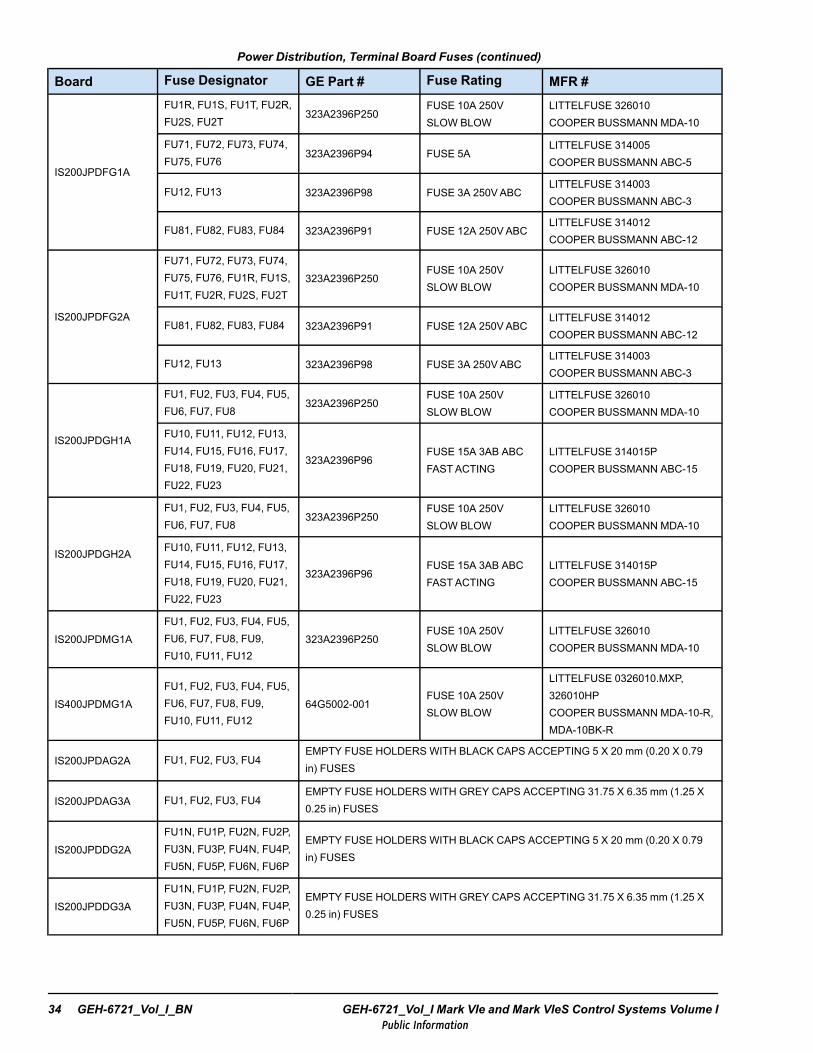
Power Distribution, Terminal Board Fuses (continued)
Board Fuse Designator GE Part # Fuse Rating MFR #
IS200JPDFG1A
FU1R, FU1S, FU1T, FU2R,FU2S, FU2T
323A2396P250FUSE 10A 250VSLOW BLOW
LITTELFUSE 326010COOPER BUSSMANN MDA-10
FU71, FU72, FU73, FU74,FU75, FU76
323A2396P94 FUSE 5ALITTELFUSE 314005COOPER BUSSMANN ABC-5
FU12, FU13 323A2396P98 FUSE 3A 250VABCLITTELFUSE 314003COOPER BUSSMANN ABC-3
FU81, FU82, FU83, FU84 323A2396P91 FUSE 12A 250VABCLITTELFUSE 314012COOPER BUSSMANN ABC-12
IS200JPDFG2A
FU71, FU72, FU73, FU74,FU75, FU76, FU1R, FU1S,FU1T, FU2R, FU2S, FU2T
323A2396P250FUSE 10A 250VSLOW BLOW
LITTELFUSE 326010COOPER BUSSMANN MDA-10
FU81, FU82, FU83, FU84 323A2396P91 FUSE 12A 250VABCLITTELFUSE 314012COOPER BUSSMANN ABC-12
FU12, FU13 323A2396P98 FUSE 3A 250VABCLITTELFUSE 314003COOPER BUSSMANN ABC-3
IS200JPDGH1A
FU1, FU2, FU3, FU4, FU5,FU6, FU7, FU8
323A2396P250FUSE 10A 250VSLOW BLOW
LITTELFUSE 326010COOPER BUSSMANN MDA-10
FU10, FU11, FU12, FU13,FU14, FU15, FU16, FU17,FU18, FU19, FU20, FU21,FU22, FU23
323A2396P96FUSE 15A 3AB ABCFASTACTING
LITTELFUSE 314015PCOOPER BUSSMANN ABC-15
IS200JPDGH2A
FU1, FU2, FU3, FU4, FU5,FU6, FU7, FU8
323A2396P250FUSE 10A 250VSLOW BLOW
LITTELFUSE 326010COOPER BUSSMANN MDA-10
FU10, FU11, FU12, FU13,FU14, FU15, FU16, FU17,FU18, FU19, FU20, FU21,FU22, FU23
323A2396P96FUSE 15A 3AB ABCFASTACTING
LITTELFUSE 314015PCOOPER BUSSMANN ABC-15
IS200JPDMG1AFU1, FU2, FU3, FU4, FU5,FU6, FU7, FU8, FU9,FU10, FU11, FU12
323A2396P250FUSE 10A 250VSLOW BLOW
LITTELFUSE 326010COOPER BUSSMANN MDA-10
IS400JPDMG1AFU1, FU2, FU3, FU4, FU5,FU6, FU7, FU8, FU9,FU10, FU11, FU12
64G5002-001FUSE 10A 250VSLOW BLOW
LITTELFUSE 0326010.MXP,326010HPCOOPER BUSSMANN MDA-10-R,MDA-10BK-R
IS200JPDAG2A FU1, FU2, FU3, FU4EMPTY FUSE HOLDERS WITH BLACK CAPS ACCEPTING 5 X 20 mm (0.20 X 0.79in) FUSES
IS200JPDAG3A FU1, FU2, FU3, FU4EMPTY FUSE HOLDERS WITH GREY CAPS ACCEPTING 31.75 X 6.35 mm (1.25 X0.25 in) FUSES
IS200JPDDG2AFU1N, FU1P, FU2N, FU2P,FU3N, FU3P, FU4N, FU4P,FU5N, FU5P, FU6N, FU6P
EMPTY FUSE HOLDERS WITH BLACK CAPS ACCEPTING 5 X 20 mm (0.20 X 0.79in) FUSES
IS200JPDDG3AFU1N, FU1P, FU2N, FU2P,FU3N, FU3P, FU4N, FU4P,FU5N, FU5P, FU6N, FU6P
EMPTY FUSE HOLDERS WITH GREY CAPS ACCEPTING 31.75 X 6.35 mm (1.25 X0.25 in) FUSES
34 GEH-6721_Vol_I_BN GEH-6721_Vol_I Mark VIe and Mark VIeS Control Systems Volume IPublic Information
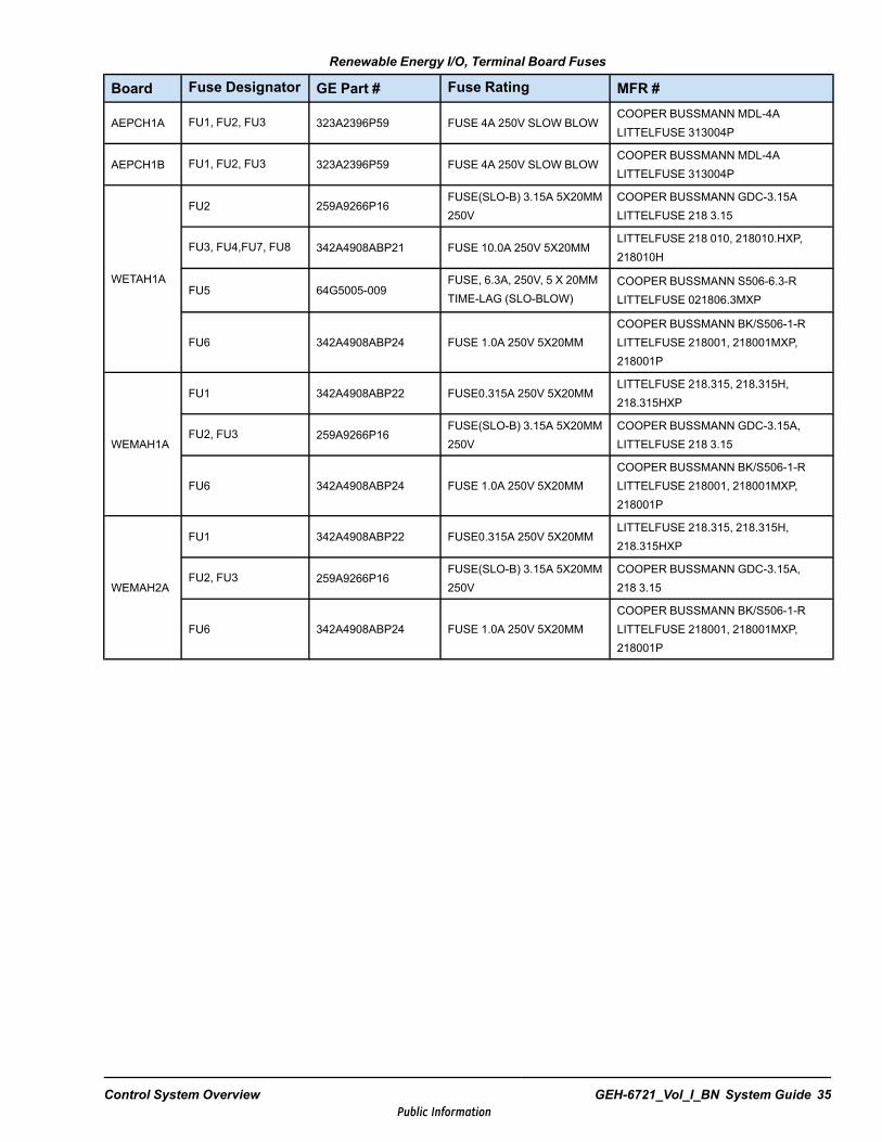
Renewable Energy I/O, Terminal Board Fuses
Board Fuse Designator GE Part # Fuse Rating MFR #
AEPCH1A FU1, FU2, FU3 323A2396P59 FUSE 4A 250V SLOW BLOWCOOPER BUSSMANN MDL-4ALITTELFUSE 313004P
AEPCH1B FU1, FU2, FU3 323A2396P59 FUSE 4A 250V SLOW BLOWCOOPER BUSSMANN MDL-4ALITTELFUSE 313004P
WETAH1A
FU2 259A9266P16FUSE(SLO-B) 3.15A 5X20MM250V
COOPER BUSSMANN GDC-3.15ALITTELFUSE 218 3.15
FU3, FU4,FU7, FU8 342A4908ABP21 FUSE 10.0A 250V 5X20MMLITTELFUSE 218 010, 218010.HXP,218010H
FU5 64G5005-009FUSE, 6.3A, 250V, 5 X 20MMTIME-LAG (SLO-BLOW)
COOPER BUSSMANN S506-6.3-RLITTELFUSE 021806.3MXP
FU6 342A4908ABP24 FUSE 1.0A 250V 5X20MMCOOPER BUSSMANN BK/S506-1-RLITTELFUSE 218001, 218001MXP,218001P
WEMAH1A
FU1 342A4908ABP22 FUSE0.315A 250V 5X20MMLITTELFUSE 218.315, 218.315H,218.315HXP
FU2, FU3 259A9266P16FUSE(SLO-B) 3.15A 5X20MM250V
COOPER BUSSMANN GDC-3.15A,LITTELFUSE 218 3.15
FU6 342A4908ABP24 FUSE 1.0A 250V 5X20MMCOOPER BUSSMANN BK/S506-1-RLITTELFUSE 218001, 218001MXP,218001P
WEMAH2A
FU1 342A4908ABP22 FUSE0.315A 250V 5X20MMLITTELFUSE 218.315, 218.315H,218.315HXP
FU2, FU3 259A9266P16FUSE(SLO-B) 3.15A 5X20MM250V
COOPER BUSSMANN GDC-3.15A,218 3.15
FU6 342A4908ABP24 FUSE 1.0A 250V 5X20MMCOOPER BUSSMANN BK/S506-1-RLITTELFUSE 218001, 218001MXP,218001P
Control System Overview GEH-6721_Vol_I_BN System Guide 35Public Information

1.5 Power DistributionThe Mark VIe and Mark VIeS control systems are designed to operate on a flexible, modular selection of power sources. Thepower distribution modules (PDM) support 115/230 Vac, 24 and 125 V dc power sources in many redundant combinations.The power applied is converted to 28 V dc for operation of the I/O packs, controllers, and switches.
Note Refer to For more information on the IONet switches, refer to theMark VIe and Mark VIeS Control Systems VolumeII: System Guide for General-purpose Applications (GEH-6721_Vol_II), the chapter PDM Power Distribution Modules. TheJPDS, JPDM, JPDG, or JPDC core power distribution board allows for the optional attachment of a PPDA I/O pack forsystem feedback.
The PDM can be divided into two substantially different categories, the core distribution system, and the branch circuitelements. They serve as the primary power management for a cabinet or series of cabinets. The branch circuit elements takethe core output and fan it into individual circuits for consumption in the cabinets. Branch circuits provide their own feedbackmechanisms, which are not part of the feedback provided by the PPDA I/O pack. The wide variety of power distributioncomponents available for use with the Mark VIe and Mark VIeS control systems allow for a flexible and scalable powerdistribution solution.
36 GEH-6721_Vol_I_BN GEH-6721_Vol_I Mark VIe and Mark VIeS Control Systems Volume IPublic Information
1.6 Redundancy OptionsThe Mark control platform provides scaleable levels of redundancy. The basic system is a single (simplex) controller withsimplex I/O and one network. The dual system has two controllers, singular or fanned TMR I/O and dual networks, whichprovides added reliability and online repair options. The TMR system has three controllers, singular or fanned TMR I/O, threenetworks, and state voting between controllers providing the maximum fault detection and availability.
1.6.1 Controller RedundancyController redundancy consists of the following:
• Simplex controller• Dual controllers• Triple redundant controllers (TMR)
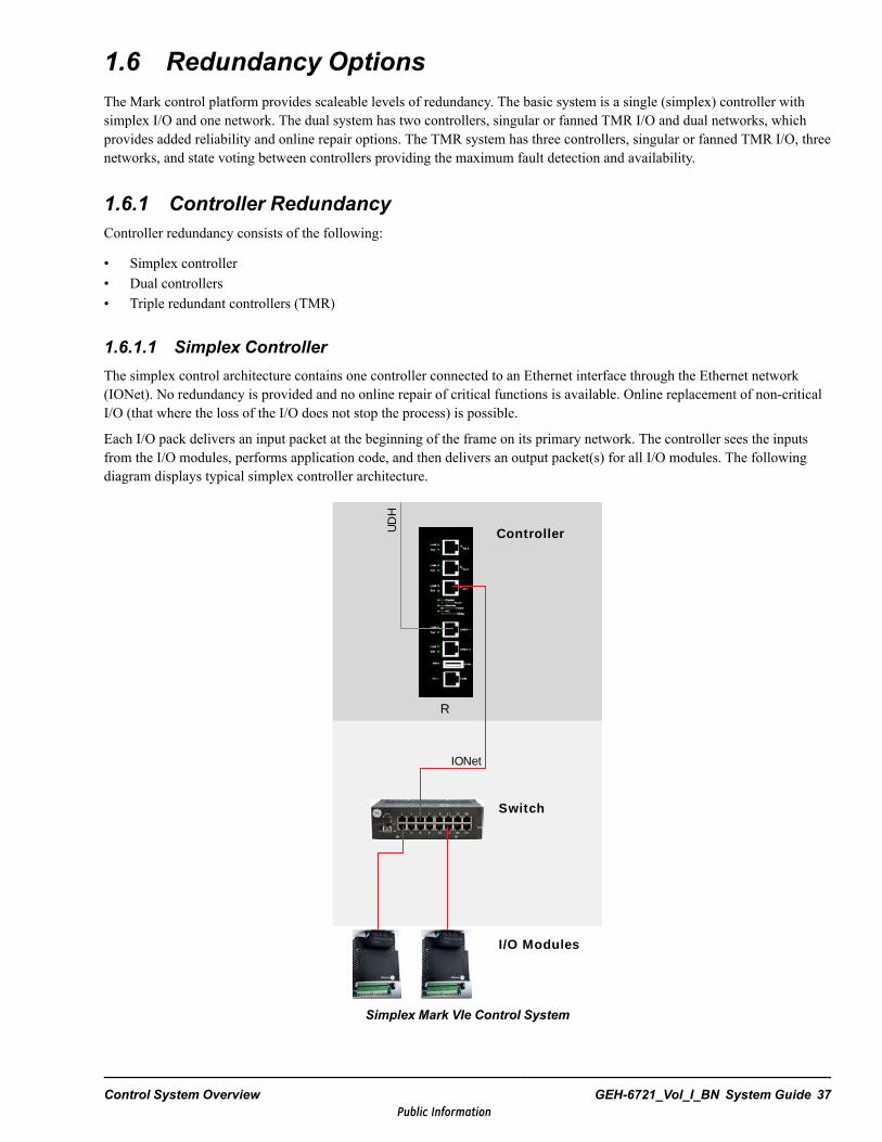
1.6.1.1 Simplex ControllerThe simplex control architecture contains one controller connected to an Ethernet interface through the Ethernet network(IONet). No redundancy is provided and no online repair of critical functions is available. Online replacement of non-criticalI/O (that where the loss of the I/O does not stop the process) is possible.
Each I/O pack delivers an input packet at the beginning of the frame on its primary network. The controller sees the inputsfrom the I/O modules, performs application code, and then delivers an output packet(s) for all I/O modules. The followingdiagram displays typical simplex controller architecture.
Switch
Controller
R
UD
H
I/O Modules
IONet
Simplex Mark VIe Control System
Control System Overview GEH-6721_Vol_I_BN System Guide 37Public Information
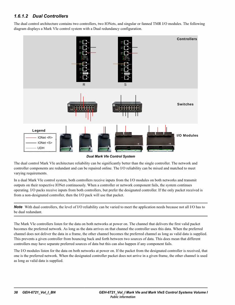
1.6.1.2 Dual ControllersThe dual control architecture contains two controllers, two IONets, and singular or fanned TMR I/O modules. The followingdiagram displays a Mark VIe control system with a Dual redundancy configuration.
Switches
Controllers
R S
I/O Modules
IONet <S>
IONet <R>
Legend
UDH
Dual Mark VIe Control System
The dual control Mark VIe architecture reliability can be significantly better than the single controller. The network andcontroller components are redundant and can be repaired online. The I/O reliability can be mixed and matched to meetvarying requirements.
In a dual Mark VIe control system, both controllers receive inputs from the I/O modules on both networks and transmitoutputs on their respective IONet continuously. When a controller or network component fails, the system continuesoperating. I/O packs receive inputs from both controllers, but prefer the designated controller. If the only packet received isfrom a non-designated controller, then the I/O pack will use that packet.
Note With dual controllers, the level of I/O reliability can be varied to meet the application needs because not all I/O has tobe dual redundant.
The Mark VIe controllers listen for the data on both networks at power on. The channel that delivers the first valid packetbecomes the preferred network. As long as the data arrives on that channel the controller uses this data. When the preferredchannel does not deliver the data in a frame, the other channel becomes the preferred channel as long as valid data is supplied.This prevents a given controller from bouncing back and forth between two sources of data. This does mean that differentcontrollers may have separate preferred sources of data but this can also happen if any component fails.
The I/O modules listen for the data on both networks at power on. If the packet from the designated controller is received, thatone is the preferred network. When the designated controller packet does not arrive in a given frame, the other channel is usedas long as valid data is supplied.
38 GEH-6721_Vol_I_BN GEH-6721_Vol_I Mark VIe and Mark VIeS Control Systems Volume IPublic Information

In a dual control system, the application logic in each controller tries to produce the same results. After many iterations ofrunning the application, it is possible for the internal data values to differ due to mathematical round off, and different pasthistory (power-up). To converge this data, the internal data (state) variables are taken from the designated controller andtransmitted to the non-designated controller for its use. This is known as state exchange.
State variables are any internal variables not immediately derived from input or control constants. Any variable that is usedprior to being re-calculated is an internal state variable.
This principle can be displayed in the following two equations:
A = B+CC = 3 x D
Assume B and D are inputs and A and C are intermediate values. Since C is used prior to being calculated, the value of Cduring the previous scan retains some state information. Therefore, C is a state variable that must be updated in thenon-designated controller if both controllers are to remain synchronized.
In the Mark VIe controller, Boolean state variables are updated on every control frame. The analog state variable updates aremultiplexed. A subset of analog state variables is updated every control frame. The controller rolls through each subset untilall state variables are transmitted.
Control System Overview GEH-6721_Vol_I_BN System Guide 39Public Information
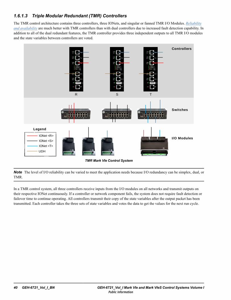
1.6.1.3 Triple Modular Redundant (TMR) ControllersThe TMR control architecture contains three controllers, three IONets, and singular or fanned TMR I/O Modules. Reliabilityand availability are much better with TMR controllers than with dual controllers due to increased fault detection capability. Inaddition to all of the dual redundant features, the TMR controller provides three independent outputs to all TMR I/O modulesand the state variables between controllers are voted.
I/O Modules
Switches
Controllers
R S T
IONet <T>
IONet <S>
IONet <R>
Legend
UDH
TMR Mark VIe Control System
Note The level of I/O reliability can be varied to meet the application needs because I/O redundancy can be simplex, dual, orTMR.
In a TMR control system, all three controllers receive inputs from the I/O modules on all networks and transmit outputs ontheir respective IONet continuously. If a controller or network component fails, the system does not require fault detection orfailover time to continue operating. All controllers transmit their copy of the state variables after the output packet has beentransmitted. Each controller takes the three sets of state variables and votes the data to get the values for the next run cycle.
40 GEH-6721_Vol_I_BN GEH-6721_Vol_I Mark VIe and Mark VIeS Control Systems Volume IPublic Information
1.6.2 I/O RedundancyThere are various options available for single and multiple packs and single and dual networks for I/O redundancy. Thefollowing are options for TMR I/O modules:
• Single Pack Dual Network I/O Module (SPDN)• Two Single Pack, Single Network (2SPSN) I/O Modules• Dual Pack, Dual Network (DPDN) I/O Module• Triple Pack, Dual Network (TPDN) I/O Module• Hot Backup I/O Module
1.6.2.1 Single Pack Dual Network I/O Module (SPDN)This configuration is typically used for non-critical single sensor I/O. A single sensor connects to a single set of acquisitionelectronics which is then connected to two networks.
• Single data acquisition• Redundant network
The I/O pack delivers input data on both networks at the beginning of the frame and receives output data from bothcontrollers at the end of the frame.
1.6.2.2 Two Single Pack, Single Network (2SPSN) I/O ModulesThis configuration is typically used for inputs where there are multiple sensors monitoring the same process points. Twosensors are connected to two independent I/O modules.
• Redundant sensors• Redundant data acquisition• Redundant network• Online repair
Each I/O pack delivers input data on a separate network at the beginning of the frame and receives output data from separatecontrollers at the end of the frame.
1.6.2.3 Dual Pack, Dual Network (DPDN) I/O ModuleThis is a special case for inputs only, using a dual pack, dual network module. A fanned input terminal board can be populatedwith two packs providing redundant data acquisition for a set of inputs.
• Redundant data acquisition• Redundant network• Online repair
Each I/O pack delivers input data on a separate network at the beginning of the frame.
Control System Overview GEH-6721_Vol_I_BN System Guide 41Public Information
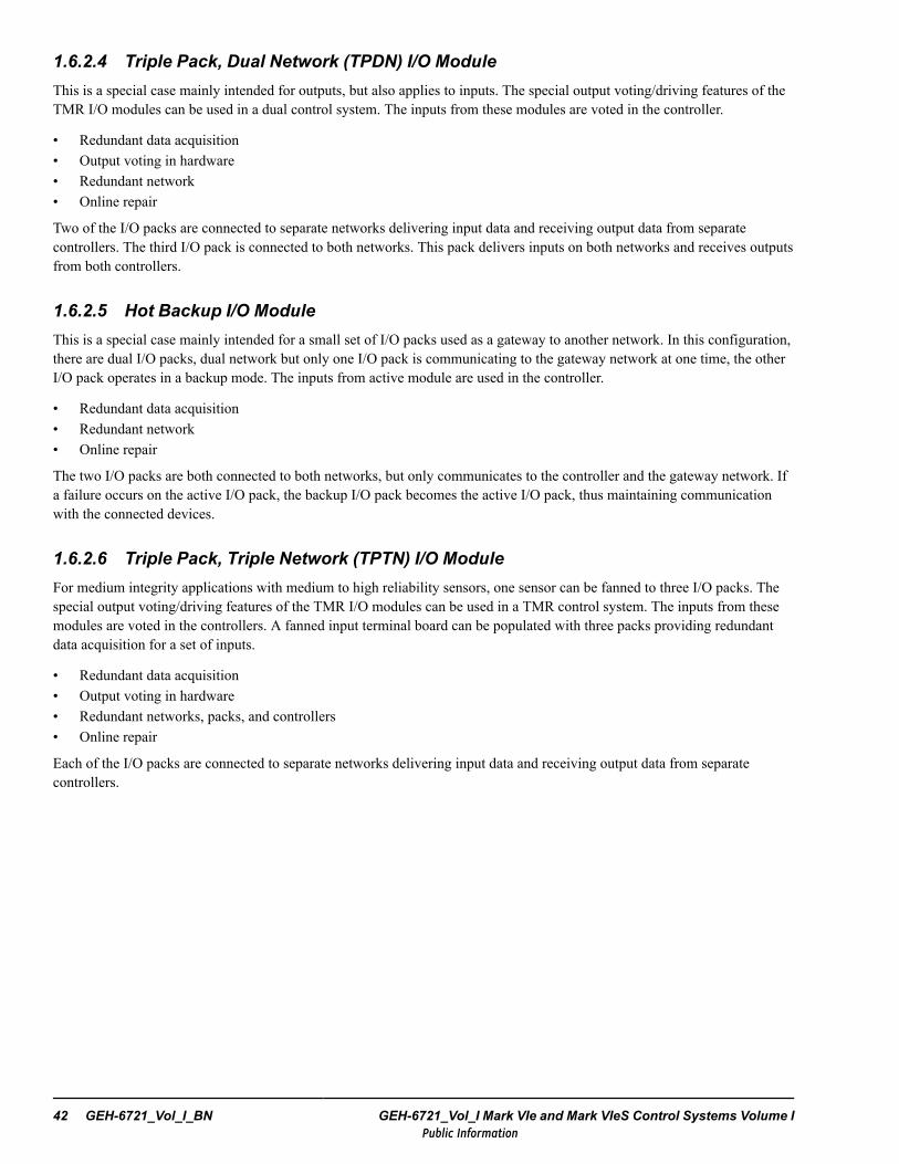
1.6.2.4 Triple Pack, Dual Network (TPDN) I/O ModuleThis is a special case mainly intended for outputs, but also applies to inputs. The special output voting/driving features of theTMR I/O modules can be used in a dual control system. The inputs from these modules are voted in the controller.
• Redundant data acquisition• Output voting in hardware• Redundant network• Online repair
Two of the I/O packs are connected to separate networks delivering input data and receiving output data from separatecontrollers. The third I/O pack is connected to both networks. This pack delivers inputs on both networks and receives outputsfrom both controllers.
1.6.2.5 Hot Backup I/O ModuleThis is a special case mainly intended for a small set of I/O packs used as a gateway to another network. In this configuration,there are dual I/O packs, dual network but only one I/O pack is communicating to the gateway network at one time, the otherI/O pack operates in a backup mode. The inputs from active module are used in the controller.
• Redundant data acquisition• Redundant network• Online repair
The two I/O packs are both connected to both networks, but only communicates to the controller and the gateway network. Ifa failure occurs on the active I/O pack, the backup I/O pack becomes the active I/O pack, thus maintaining communicationwith the connected devices.
1.6.2.6 Triple Pack, Triple Network (TPTN) I/O ModuleFor medium integrity applications with medium to high reliability sensors, one sensor can be fanned to three I/O packs. Thespecial output voting/driving features of the TMR I/O modules can be used in a TMR control system. The inputs from thesemodules are voted in the controllers. A fanned input terminal board can be populated with three packs providing redundantdata acquisition for a set of inputs.
• Redundant data acquisition• Output voting in hardware• Redundant networks, packs, and controllers• Online repair
Each of the I/O packs are connected to separate networks delivering input data and receiving output data from separatecontrollers.
42 GEH-6721_Vol_I_BN GEH-6721_Vol_I Mark VIe and Mark VIeS Control Systems Volume IPublic Information
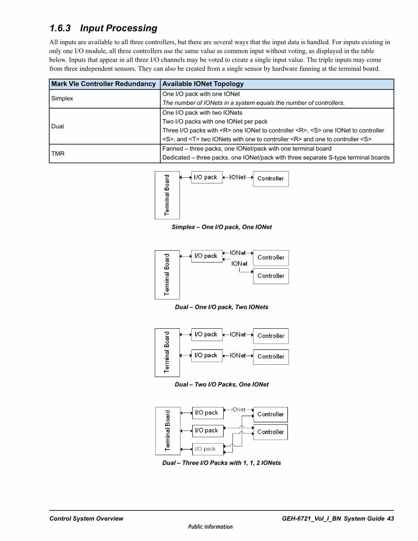
1.6.3 Input ProcessingAll inputs are available to all three controllers, but there are several ways that the input data is handled. For inputs existing inonly one I/O module, all three controllers use the same value as common input without voting, as displayed in the tablebelow. Inputs that appear in all three I/O channels may be voted to create a single input value. The triple inputs may comefrom three independent sensors. They can also be created from a single sensor by hardware fanning at the terminal board.
Mark VIe Controller Redundancy Available IONet Topology
SimplexOne I/O pack with one IONetThe number of IONets in a system equals the number of controllers.
Dual
One I/O pack with two IONetsTwo I/O packs with one IONet per packThree I/O packs with <R> one IONet to controller <R>, <S> one IONet to controller<S>, and <T> two IONets with one to controller <R> and one to controller <S>
TMRFanned – three packs, one IONet/pack with one terminal boardDedicated – three packs, one IONet/pack with three separate S-type terminal boards
Simplex – One I/O pack, One IONet
Dual – One I/O pack, Two IONets
Dual – Two I/O Packs, One IONet
Dual – Three I/O Packs with 1, 1, 2 IONets
Control System Overview GEH-6721_Vol_I_BN System Guide 43Public Information
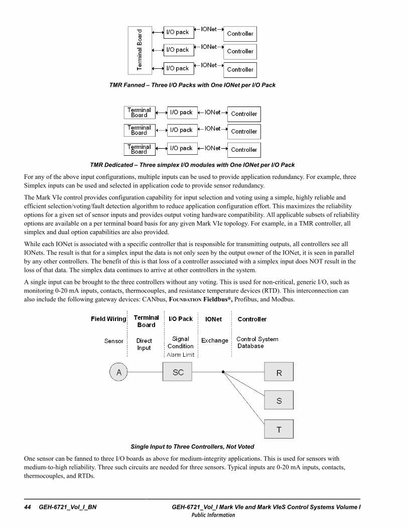
TMR Fanned – Three I/O Packs with One IONet per I/O Pack
TMR Dedicated – Three simplex I/O modules with One IONet per I/O Pack
For any of the above input configurations, multiple inputs can be used to provide application redundancy. For example, threeSimplex inputs can be used and selected in application code to provide sensor redundancy.
The Mark VIe control provides configuration capability for input selection and voting using a simple, highly reliable andefficient selection/voting/fault detection algorithm to reduce application configuration effort. This maximizes the reliabilityoptions for a given set of sensor inputs and provides output voting hardware compatibility. All applicable subsets of reliabilityoptions are available on a per terminal board basis for any given Mark VIe topology. For example, in a TMR controller, allsimplex and dual option capabilities are also provided.
While each IONet is associated with a specific controller that is responsible for transmitting outputs, all controllers see allIONets. The result is that for a simplex input the data is not only seen by the output owner of the IONet, it is seen in parallelby any other controllers. The benefit of this is that loss of a controller associated with a simplex input does NOT result in theloss of that data. The simplex data continues to arrive at other controllers in the system.
A single input can be brought to the three controllers without any voting. This is used for non-critical, generic I/O, such asmonitoring 0-20 mA inputs, contacts, thermocouples, and resistance temperature devices (RTD). This interconnection canalso include the following gateway devices: CANbus, FOUNDATION Fieldbus®, Profibus, and Modbus.
Single Input to Three Controllers, Not Voted
One sensor can be fanned to three I/O boards as above for medium-integrity applications. This is used for sensors withmedium-to-high reliability. Three such circuits are needed for three sensors. Typical inputs are 0-20 mA inputs, contacts,thermocouples, and RTDs.
44 GEH-6721_Vol_I_BN GEH-6721_Vol_I Mark VIe and Mark VIeS Control Systems Volume IPublic Information

One Sensor with Fanned Input and Software Voting
Three independent sensors can be brought into the controllers without voting to provide the individual sensor values to theapplication. Median values can be selected in the controller if required. This configuration, displayed in the following figure,is used for special applications only.
Three Independent Sensors with Common Input, Not Voted
Control System Overview GEH-6721_Vol_I_BN System Guide 45Public Information
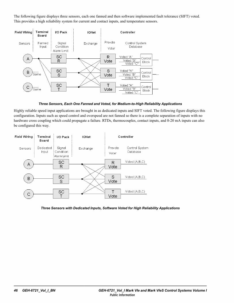
The following figure displays three sensors, each one fanned and then software implemented fault tolerance (SIFT) voted.This provides a high reliability system for current and contact inputs, and temperature sensors.
Three Sensors, Each One Fanned and Voted, for Medium-to-High Reliability Applications
Highly reliable speed input applications are brought in as dedicated inputs and SIFT voted. The following figure displays thisconfiguration. Inputs such as speed control and overspeed are not fanned so there is a complete separation of inputs with nohardware cross coupling which could propagate a failure. RTDs, thermocouples, contact inputs, and 0-20 mA inputs can alsobe configured this way.
Three Sensors with Dedicated Inputs, Software Voted for High Reliability Applications
46 GEH-6721_Vol_I_BN GEH-6721_Vol_I Mark VIe and Mark VIeS Control Systems Volume IPublic Information
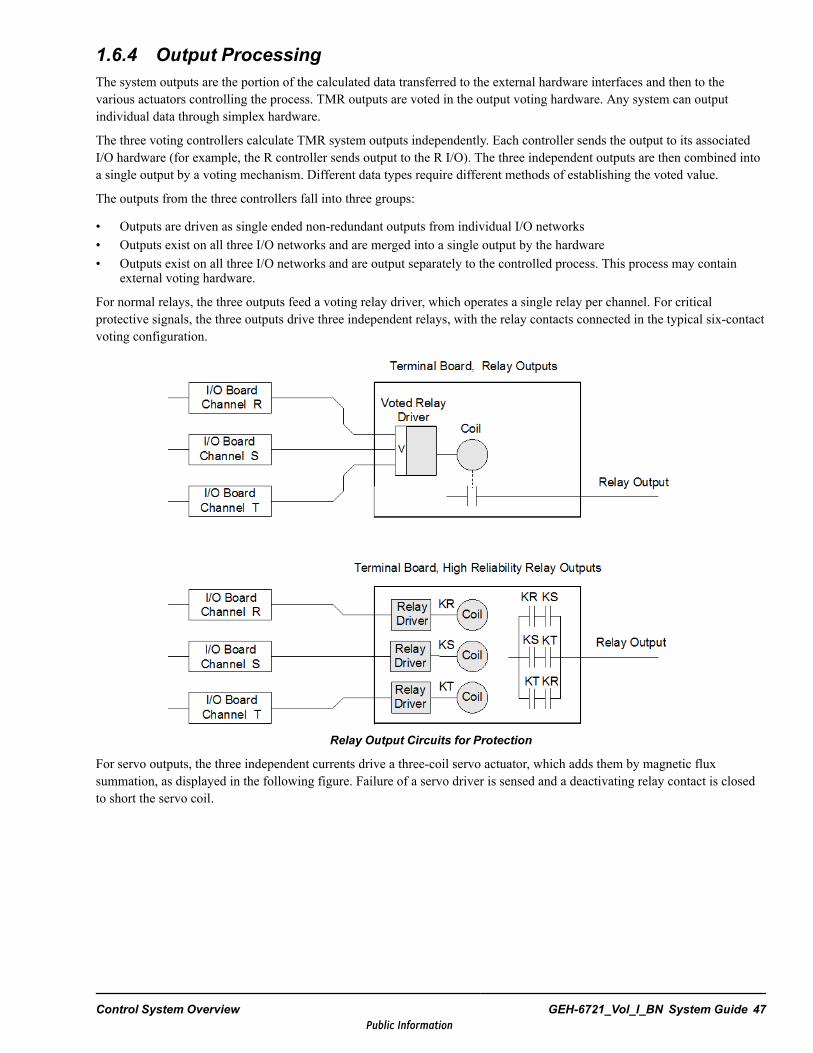
1.6.4 Output ProcessingThe system outputs are the portion of the calculated data transferred to the external hardware interfaces and then to thevarious actuators controlling the process. TMR outputs are voted in the output voting hardware. Any system can outputindividual data through simplex hardware.
The three voting controllers calculate TMR system outputs independently. Each controller sends the output to its associatedI/O hardware (for example, the R controller sends output to the R I/O). The three independent outputs are then combined intoa single output by a voting mechanism. Different data types require different methods of establishing the voted value.
The outputs from the three controllers fall into three groups:
• Outputs are driven as single ended non-redundant outputs from individual I/O networks• Outputs exist on all three I/O networks and are merged into a single output by the hardware• Outputs exist on all three I/O networks and are output separately to the controlled process. This process may contain
external voting hardware.
For normal relays, the three outputs feed a voting relay driver, which operates a single relay per channel. For criticalprotective signals, the three outputs drive three independent relays, with the relay contacts connected in the typical six-contactvoting configuration.
Relay Output Circuits for Protection
For servo outputs, the three independent currents drive a three-coil servo actuator, which adds them by magnetic fluxsummation, as displayed in the following figure. Failure of a servo driver is sensed and a deactivating relay contact is closedto short the servo coil.
Control System Overview GEH-6721_Vol_I_BN System Guide 47Public Information
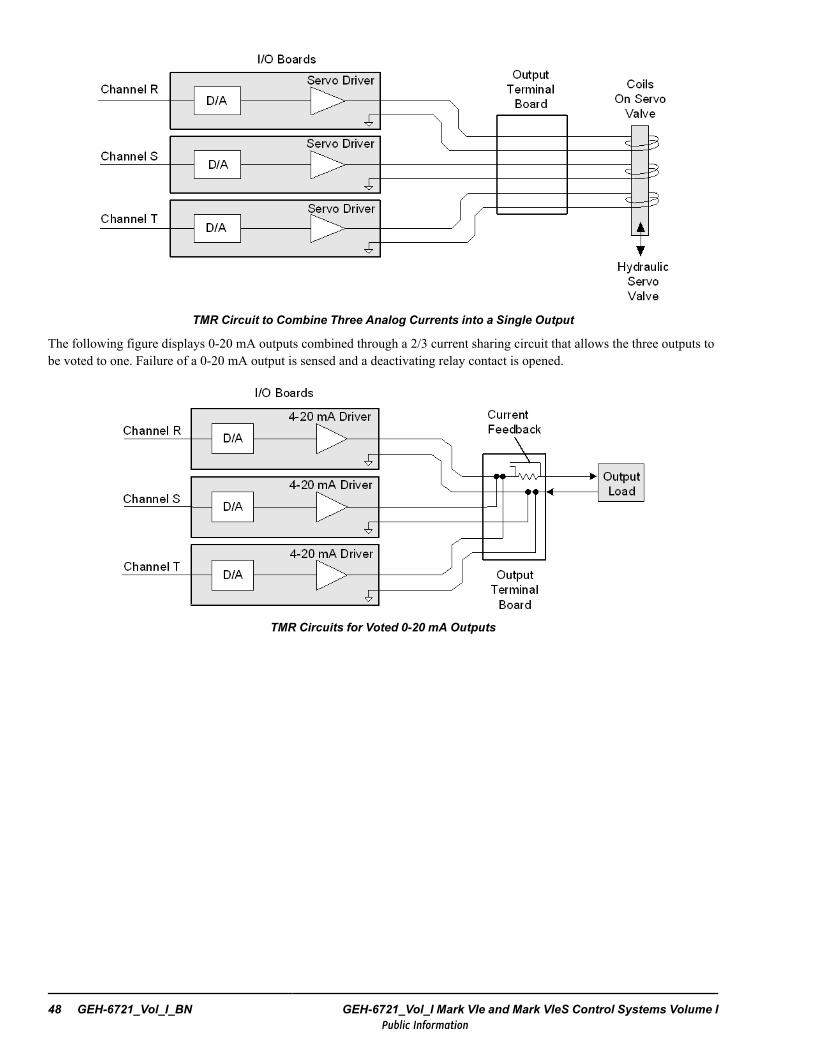
TMR Circuit to Combine Three Analog Currents into a Single Output
The following figure displays 0-20 mA outputs combined through a 2/3 current sharing circuit that allows the three outputs tobe voted to one. Failure of a 0-20 mA output is sensed and a deactivating relay contact is opened.
TMR Circuits for Voted 0-20 mA Outputs
48 GEH-6721_Vol_I_BN GEH-6721_Vol_I Mark VIe and Mark VIeS Control Systems Volume IPublic Information
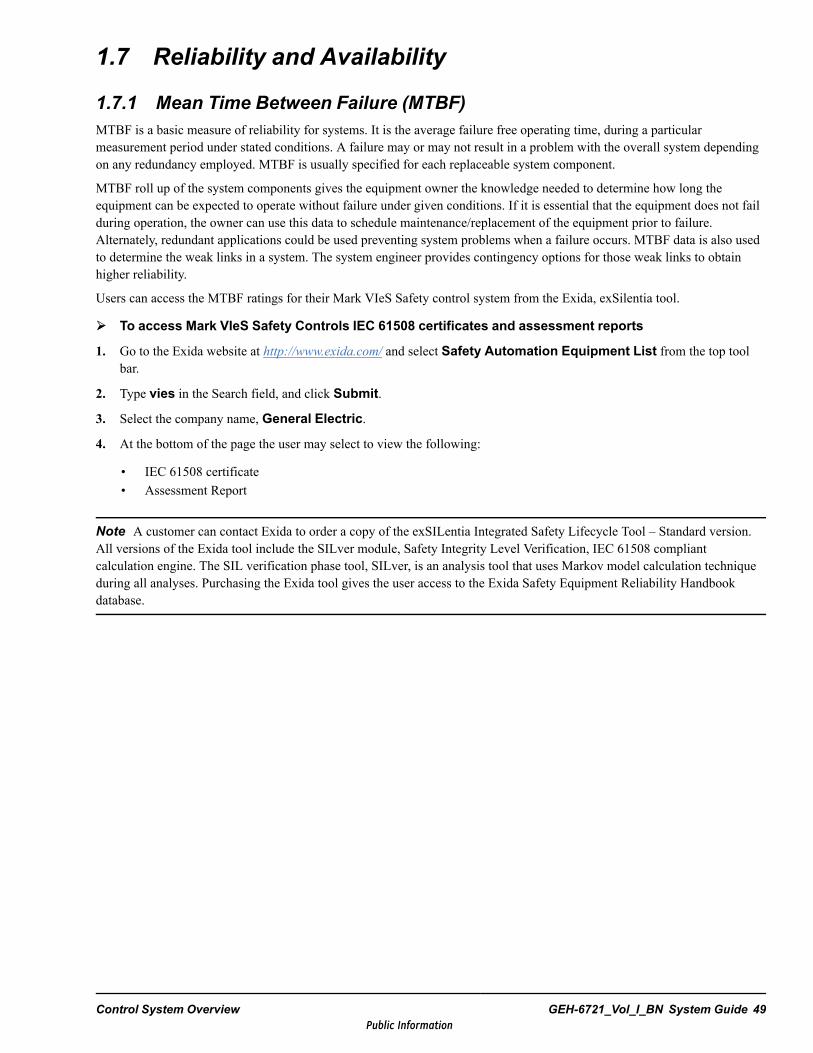
1.7 Reliability and Availability
1.7.1 Mean Time Between Failure (MTBF)MTBF is a basic measure of reliability for systems. It is the average failure free operating time, during a particularmeasurement period under stated conditions. A failure may or may not result in a problem with the overall system dependingon any redundancy employed. MTBF is usually specified for each replaceable system component.
MTBF roll up of the system components gives the equipment owner the knowledge needed to determine how long theequipment can be expected to operate without failure under given conditions. If it is essential that the equipment does not failduring operation, the owner can use this data to schedule maintenance/replacement of the equipment prior to failure.Alternately, redundant applications could be used preventing system problems when a failure occurs. MTBF data is also usedto determine the weak links in a system. The system engineer provides contingency options for those weak links to obtainhigher reliability.
Users can access the MTBF ratings for their Mark VIeS Safety control system from the Exida, exSilentia tool.
To access Mark VIeS Safety Controls IEC 61508 certificates and assessment reports
1. Go to the Exida website at http://www.exida.com/ and select Safety Automation Equipment List from the top toolbar.
2. Type vies in the Search field, and click Submit.
3. Select the company name, General Electric.
4. At the bottom of the page the user may select to view the following:
• IEC 61508 certificate• Assessment Report
Note A customer can contact Exida to order a copy of the exSILentia Integrated Safety Lifecycle Tool – Standard version.All versions of the Exida tool include the SILver module, Safety Integrity Level Verification, IEC 61508 compliantcalculation engine. The SIL verification phase tool, SILver, is an analysis tool that uses Markov model calculation techniqueduring all analyses. Purchasing the Exida tool gives the user access to the Exida Safety Equipment Reliability Handbookdatabase.
Control System Overview GEH-6721_Vol_I_BN System Guide 49Public Information

1.7.2 Mean Time Between Forced Outage (MTBFO)MTBFO is a measure of system availability, which includes the effects of any fault tolerance that may exist. This averagetime between failures causes the loss of system functions.
The engineer must be very aware of MTBF and MTBFO when designing a reliable continuous system. To maximize theMTBFO, Mark VIe control systems undergo evaluation of all system component MTBF values. The effects of failures andcontingency operation are then analyzed to maximizing MTBFO.
To continue operation after a critical system component has failed, a control must have one or more backups in place(redundancy) to improve the MTBFO significantly above that of a simplex control. The simplest method is adding a secondcomponent that takes over the critical function when a fault is detected.
The redundancy in the system can be either active or standby. The Mark VIe control uses active redundancy and has allcomponents operating simultaneously. Standby redundancy activates backup systems after a failure is detected.
Realizing the full benefits of redundancy, a system failure must be detectable for the control to bypass it. In a dual control,gross failures are readily detectable while subtle failures are more difficult to detect. TMR controls, using two out of threevoting, are always able to select a valid value when presented with any single failure.
Depending on the equipment, the time required to detect the fault and switch to the new component may behours/minutes/seconds/milliseconds. In the case of fuel-flow control to a turbine, this is required to be done in milliseconds.
When a redundant control bypasses a failure, it is required that the system annunciate the presence of the failure and thatrepairs be completed in a timely fashion. The term, mean time to repair (MTTR), refers to the time it takes to identify andrepair a given failure. The Mark VIe control is designed to support a MTTR of four hours. This preserves the MTBFObenefits of redundancy resulting in unequaled system reliability. A control is used to run the system as well as detect systemfailures. In a dual control, configured for one out of two to run, it is often necessary to add dedicated tripping controls foreach critical trip system. This is done to yield running reliability while maintaining required tripping reliability.
ATMR control normally configures the control for two out of three selection. This yields high running and tripping reliabilityfrom the primary control. Additional dedicated tripping controls can be used to achieve even higher tripping reliability, butthey must also be TMR to preserve running reliability.
50 GEH-6721_Vol_I_BN GEH-6721_Vol_I Mark VIe and Mark VIeS Control Systems Volume IPublic Information
1.7.3 Fault DetectionA system offering redundancy can be less reliable than a non-redundant system. The system must be able to detect andannunciate faults so it can be repaired before a forced outage occurs. Fault detection is needed to ensure a component or groupof components are operating properly. Fault detection is achieved through one or more of the following methods.
• Operator inspection of the process• Operator inspection of the equipment.• Special hardware circuits to monitor operation• Hardware and software watchdogs• Software logic• Software heartbeats
Complex control systems have many potential failure points. This can be very costly and time consuming to create foolprooffault detection. Failure to control the outputs of a system is the most damaging. Fault detection must be determined as close tothe output as possible to achieve the highest level of reliability. With the Mark VIe control configured using triple redundantcontrollers and I/O modules, a high level of detection and fault masking is provided by voting the outputs of all threecontrollers and monitoring discrepancies.
All Mark VIe control systems benefit from the fault detection design of the I/O packs. Every pack includes function-specificfault detection methods attempting to confirm correct operation. This is made possible by the powerful local processing that ispresent in each input and output pack. Some examples of this include:
• Analog to digital (A/D) converters are compared to a reference standard each conversion cycle. If the convertedcalibration input falls outside of acceptable ranges, the pack declares bad health.
• Analog output 0-20 mA use a small current-sense resistor on the output terminal board. This output is read back througha separate A/D converter and compared to the commanded value. A difference between the commanded and actual valueexceeding an acceptable level results in the output being declared in bad health.
• Discrete input opto-isolators are periodically forced to an on condition, then forced off. This is done independently of theactual input and is fast enough not to interfere with the sequence of events (SOE) time capture. If any signal path is stuckand does not respond to the test command, the signal is declared in bad health.
1.7.4 Online RepairWhen a component failure is detected and healed in the control system on a critical path, a potential failure has been avoided.Subsequent actions can include:
Option 1- Continue running until the backup component fails.
Option 2 - Continue running until the system is brought down in a controlled manner to replace the failed component.
Option 3 - Replace the component online.
Option 1 is not recommended. A redundant system, where the MTTR is infinite can have a lower total reliability than asimplex system.
Option 2 is a valid procedure for some processes needing predictable mission times. Many controlled processes cannot beeasily scheduled for a shut down.
Note As MTTR increases from the expected four hours to infinite, the system reliability can decline from significantlygreater down to less than a simplex system reliability. Repair should be accomplished as soon as possible.
Option 3 is required to get the maximum benefit from redundant systems with long mission times. In dual or triple redundantMark VIe controller applications, the controllers and redundant I/O packs can be replaced online.
Control System Overview GEH-6721_Vol_I_BN System Guide 51Public Information
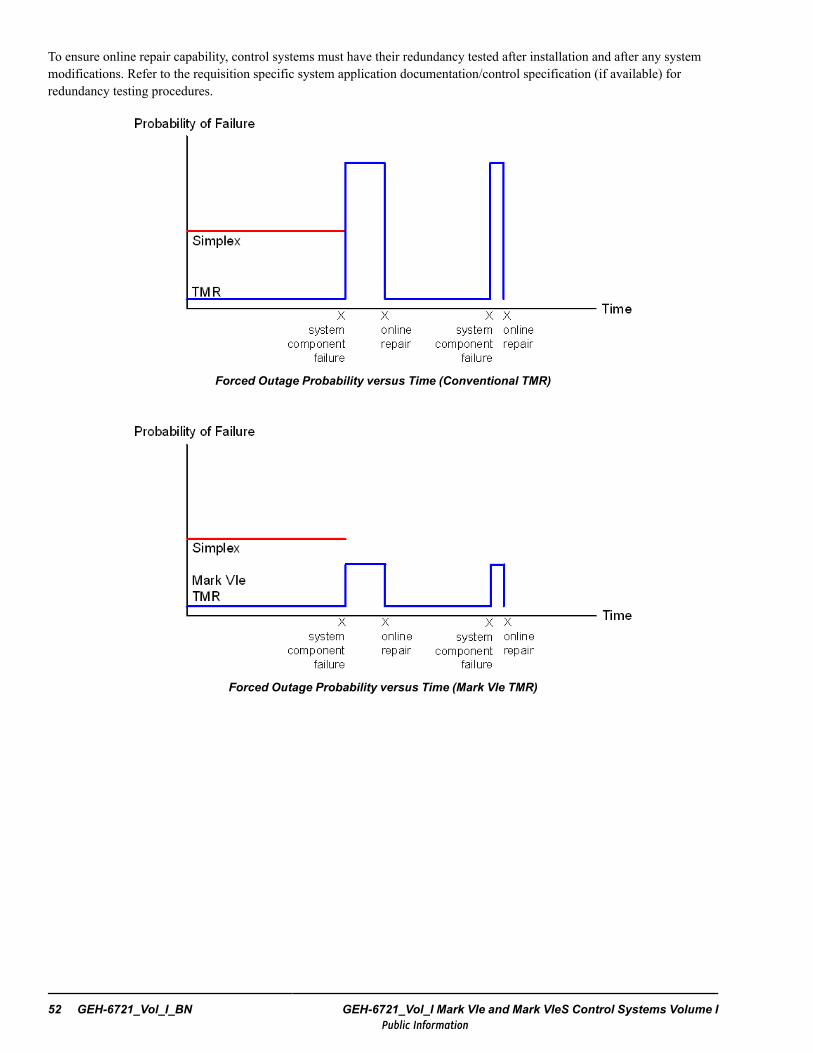
To ensure online repair capability, control systems must have their redundancy tested after installation and after any systemmodifications. Refer to the requisition specific system application documentation/control specification (if available) forredundancy testing procedures.
Forced Outage Probability versus Time (Conventional TMR)
Forced Outage Probability versus Time (Mark VIe TMR)
52 GEH-6721_Vol_I_BN GEH-6721_Vol_I Mark VIe and Mark VIeS Control Systems Volume IPublic Information

1.7.5 Designated ControllerAlthough three controllers, R, S, and T, contain identical hardware and software, some of the functions performed are unique.A single designated controller can perform the following functions:
• Supply initialization data to the other two controllers at start-up• Keep the master time clock• Supply variable state information to the other controllers if one fails
For the purposes of deciding which controller is to be the designated controller, each controller nominates itself on aweighting algorithm. The nominating values are voted among the controllers and the majority value is used. If there is a tie, orno majority, the priority is R, then S, and then T. If a designated controller is powered down and later powered up, thedesignated controller will move and not come back if all controllers are equal. This ensures that a toggling designatedcontroller is not automatically reselected.
Designated controller selection is based on:
• Control state• UDH connectivity• IONet connectivity• NVRAM health
1.7.6 Communication LossEach output pack monitors the IONet for valid commands from one or two controllers. In the event that a valid command isnot received within an expected time the pack declares the communication as being lost. Upon loss of communication thepack action is configurable. The pack can continue to hold the last commanded value indefinitely or it can be commanded togo to a specified output state. The default action is to go to a power-down state, the same as if the power were removed fromthe pack.
Note Refer to specific I/O pack documentation in Mark VIe and Mark VIeS Control Systems Volume II: System Guide forGeneral-purpose Applications (GEH-6721_Vol_II).
For critical loops, the default action is the only acceptable choice. The other options are provided for non-critical loops, whererunning liability may be enhanced by an alternate output.
1.7.7 State ExchangeTo keep multiple controllers in synchronization, the Mark VIe control efficiently exchanges the necessary state informationthrough the IONet. State information includes calculated values such as timers, counters, integrators, and logic signals such asbi-stable relays, momentary logic with seal-in, and cross-linked relay circuits. State information is voted in TMR controllersand follows the designated controller in dual or faulted TMR systems.
1.7.8 VotingVoting in the Mark VIe control is separated into analog and logic voting. Additionally, fault detection mechanisms directlychoose owned inputs and designated states.
Control System Overview GEH-6721_Vol_I_BN System Guide 53Public Information
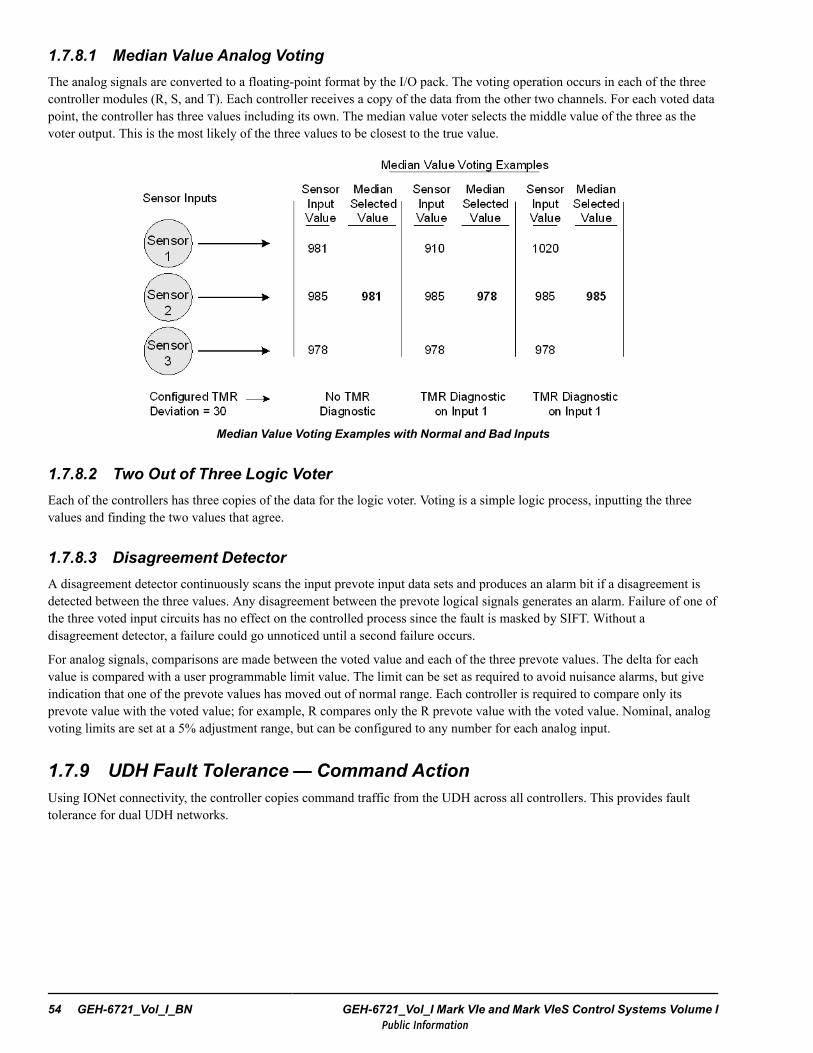
1.7.8.1 Median Value Analog VotingThe analog signals are converted to a floating-point format by the I/O pack. The voting operation occurs in each of the threecontroller modules (R, S, and T). Each controller receives a copy of the data from the other two channels. For each voted datapoint, the controller has three values including its own. The median value voter selects the middle value of the three as thevoter output. This is the most likely of the three values to be closest to the true value.
Median Value Voting Examples with Normal and Bad Inputs
1.7.8.2 Two Out of Three Logic VoterEach of the controllers has three copies of the data for the logic voter. Voting is a simple logic process, inputting the threevalues and finding the two values that agree.
1.7.8.3 Disagreement DetectorA disagreement detector continuously scans the input prevote input data sets and produces an alarm bit if a disagreement isdetected between the three values. Any disagreement between the prevote logical signals generates an alarm. Failure of one ofthe three voted input circuits has no effect on the controlled process since the fault is masked by SIFT. Without adisagreement detector, a failure could go unnoticed until a second failure occurs.
For analog signals, comparisons are made between the voted value and each of the three prevote values. The delta for eachvalue is compared with a user programmable limit value. The limit can be set as required to avoid nuisance alarms, but giveindication that one of the prevote values has moved out of normal range. Each controller is required to compare only itsprevote value with the voted value; for example, R compares only the R prevote value with the voted value. Nominal, analogvoting limits are set at a 5% adjustment range, but can be configured to any number for each analog input.
1.7.9 UDH Fault Tolerance — Command ActionUsing IONet connectivity, the controller copies command traffic from the UDH across all controllers. This provides faulttolerance for dual UDH networks.
54 GEH-6721_Vol_I_BN GEH-6721_Vol_I Mark VIe and Mark VIeS Control Systems Volume IPublic Information

1.7.10 Forced VariablesThe controller has a feature called Forced Variables. This allows the maintenance technician using application software to setanalog or logical variables to forced values. Variables remain at the forced value until unforced. Both compute and inputprocessing respect forcing. Any applied forcing is preserved through power down or restart of the controller.
Warning
Logic Forcing is for offline software checkout and troubleshooting and should only beused in conjunction with proper lockout/tag out procedures. Forcing of protectivefunctions is never permissible for an operating unit.
1.7.11 Peer I/OIn addition to the data from the I/O modules, there is a class of data coming from other controllers in other cabinets connectedthrough the UDH network. For integrated systems, this network provides a data path between multiple turbine controllers andpossibly the controls for the generator, the exciter, or the HRSG/boiler.
Selected signals from the controller database can be mapped into pages of peer outputs that are broadcast periodically on theUDH I/O to peer controllers. For TMR systems, the UDH communicator performs this action using the data from its internaldatabase. In the event of a redundant UDH network failure, the controller will request data over the remaining network, theIONet.
Control System Overview GEH-6721_Vol_I_BN System Guide 55Public Information

1.7.12 Rate of ResponseMark VIe and Mark VIeS controllers can run at a variety of frame rates to meet the application needs of the industrial control solution. Control systems are tunedaccordingly, based on a variety of factors including: complexity of controller application logic, processor type, and number of I/O and other interfaces used. The followingdiagram provides an example of typical processes that occur during a single controller frame in sequence.
Time
TMR set ofMark VIe Controllers
NotesAssumes a Triple Modular Redundant (T MR) configuration, versus dual, or simplex
Subsystem activities identified with a gray rectangle
Activities that span multiple subsystems identified with a dashed
TMR IONet
TMR Mark VIeControl I/O
Start of frame
Transmission ofoutputs fromcontrollers to I/Opacks
Input and state variables copied into variable space inprep for execution of control logic (application code)
Control LogicTime to execute based on quantity and complexity of
control blocks
Synchronization of data between R,S, and T controllers using IONet
Fresh state of outputsapplied to terminal blockscrews, latency isdependent on circuit type
I/O packs sample inputs,latency is dependent oncircuit type
Transmission ofinputs from I/Opacks tocontrollers
End of frame
Mark VIe Subsystem
brown rectangle
56 GEH-6721_Vol_I_BN GEH-6721_Vol_I Mark VIe and Mark VIeS Control Systems Volume IPublic Information
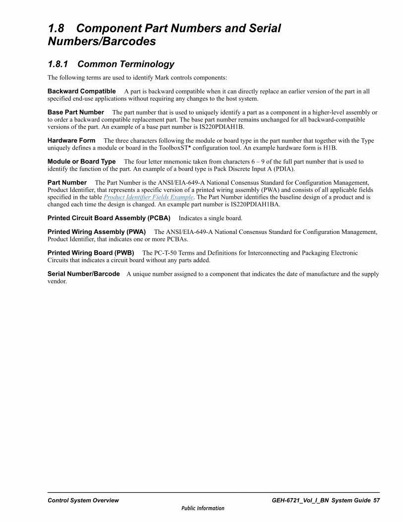
1.8 Component Part Numbers and SerialNumbers/Barcodes
1.8.1 Common TerminologyThe following terms are used to identify Mark controls components:
Backward Compatible A part is backward compatible when it can directly replace an earlier version of the part in allspecified end-use applications without requiring any changes to the host system.
Base Part Number The part number that is used to uniquely identify a part as a component in a higher-level assembly orto order a backward compatible replacement part. The base part number remains unchanged for all backward-compatibleversions of the part. An example of a base part number is IS220PDIAH1B.
Hardware Form The three characters following the module or board type in the part number that together with the Typeuniquely defines a module or board in the ToolboxST* configuration tool. An example hardware form is H1B.
Module or Board Type The four letter mnemonic taken from characters 6 – 9 of the full part number that is used toidentify the function of the part. An example of a board type is Pack Discrete Input A (PDIA).
Part Number The Part Number is the ANSI/EIA-649-A National Consensus Standard for Configuration Management,Product Identifier, that represents a specific version of a printed wiring assembly (PWA) and consists of all applicable fieldsspecified in the table Product Identifier Fields Example. The Part Number identifies the baseline design of a product and ischanged each time the design is changed. An example part number is IS220PDIAH1BA.
Printed Circuit Board Assembly (PCBA) Indicates a single board.
Printed Wiring Assembly (PWA) The ANSI/EIA-649-A National Consensus Standard for Configuration Management,Product Identifier, that indicates one or more PCBAs.
Printed Wiring Board (PWB) The PC-T-50 Terms and Definitions for Interconnecting and Packaging ElectronicCircuits that indicates a circuit board without any parts added.
Serial Number/Barcode A unique number assigned to a component that indicates the date of manufacture and the supplyvendor.
Control System Overview GEH-6721_Vol_I_BN System Guide 57Public Information
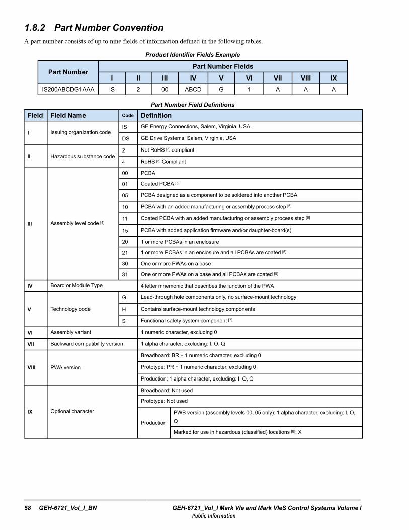
1.8.2 Part Number ConventionA part number consists of up to nine fields of information defined in the following tables.
Product Identifier Fields Example
Part NumberPart Number Fields
I II III IV V VI VII VIII IXIS200ABCDG1AAA IS 2 00 ABCD G 1 A A A
Part Number Field Definitions
Field Field Name Code Definition
I Issuing organization codeIS GE Energy Connections, Salem, Virginia, USA
DS GE Drive Systems, Salem, Virginia, USA
II Hazardous substance code2 Not RoHS [3] compliant
4 RoHS [3] Compliant
III Assembly level code [4]
00 PCBA
01 Coated PCBA [5]
05 PCBA designed as a component to be soldered into another PCBA
10 PCBA with an added manufacturing or assembly process step [6]
11 Coated PCBA with an added manufacturing or assembly process step [6]
15 PCBA with added application firmware and/or daughter-board(s)
20 1 or more PCBAs in an enclosure
21 1 or more PCBAs in an enclosure and all PCBAs are coated [5]
30 One or more PWAs on a base
31 One or more PWAs on a base and all PCBAs are coated [5]
IV Board or Module Type 4 letter mnemonic that describes the function of the PWA
V Technology code
G Lead-through hole components only, no surface-mount technology
H Contains surface-mount technology components
S Functional safety system component [7]
VI Assembly variant 1 numeric character, excluding 0
VII Backward compatibility version 1 alpha character, excluding: I, O, Q
VIII PWA version
Breadboard: BR + 1 numeric character, excluding 0
Prototype: PR + 1 numeric character, excluding 0
Production: 1 alpha character, excluding: I, O, Q
IX Optional character
Breadboard: Not used
Prototype: Not used
Production
PWB version (assembly levels 00, 05 only): 1 alpha character, excluding: I, O,Q
Marked for use in hazardous (classified) locations [8]: X
58 GEH-6721_Vol_I_BN GEH-6721_Vol_I Mark VIe and Mark VIeS Control Systems Volume IPublic Information
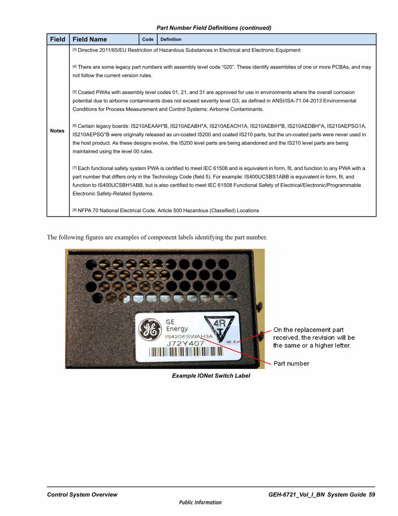
Part Number Field Definitions (continued)
Field Field Name Code Definition
Notes
[3] Directive 2011/65/EU Restriction of Hazardous Substances in Electrical and Electronic Equipment
[4] There are some legacy part numbers with assembly level code “020”. These identify assemblies of one or more PCBAs, and maynot follow the current version rules.
[5] Coated PWAs with assembly level codes 01, 21, and 31 are approved for use in environments where the overall corrosionpotential due to airborne contaminants does not exceed severity level G3, as defined in ANSI/ISA-71.04-2013 EnvironmentalConditions for Process Measurement and Control Systems: Airborne Contaminants.
[6] Certain legacy boards: IS210AEAAH*B, IS210AEABH*A, IS210AEACH1A, IS210AEBIH*B, IS210AEDBH*A, IS210AEPSG1A,IS210AEPSG*B were originally released as un-coated IS200 and coated IS210 parts, but the un-coated parts were never used inthe host product. As these designs evolve, the IS200 level parts are being abandoned and the IS210 level parts are beingmaintained using the level 00 rules.
[7] Each functional safety system PWA is certified to meet IEC 61508 and is equivalent in form, fit, and function to any PWA with apart number that differs only in the Technology Code (field 5). For example: IS400UCSBS1ABB is equivalent in form, fit, andfunction to IS400UCSBH1ABB, but is also certified to meet IEC 61508 Functional Safety of Electrical/Electronic/ProgrammableElectronic Safety-Related Systems.
[8] NFPA 70 National Electrical Code, Article 500 Hazardous (Classified) Locations
The following figures are examples of component labels identifying the part number.
Example IONet Switch Label
Control System Overview GEH-6721_Vol_I_BN System Guide 59Public Information

UCPA part number
Example UCPA Controller Label
60 GEH-6721_Vol_I_BN GEH-6721_Vol_I Mark VIe and Mark VIeS Control Systems Volume IPublic Information
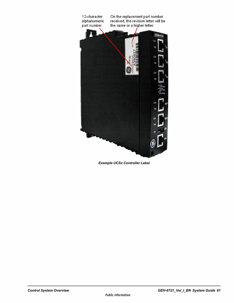
Example UCSx Controller Label
Control System Overview GEH-6721_Vol_I_BN System Guide 61Public Information

On the replacement, the revision letter will be the same or a higher letter.
Part number
Example I/O Pack Label
Internal GE employees and certain third-party parts suppliers can use the ENOVIA PLM tool to search for parts. Thefollowing Power Generation PLM web portal is available to assist with account registration and training on how to use thetool to search for parts:http://colab.ge.com/dashboard/canvas/v/518d03b3bf1d408e570001c9/home
62 GEH-6721_Vol_I_BN GEH-6721_Vol_I Mark VIe and Mark VIeS Control Systems Volume IPublic Information
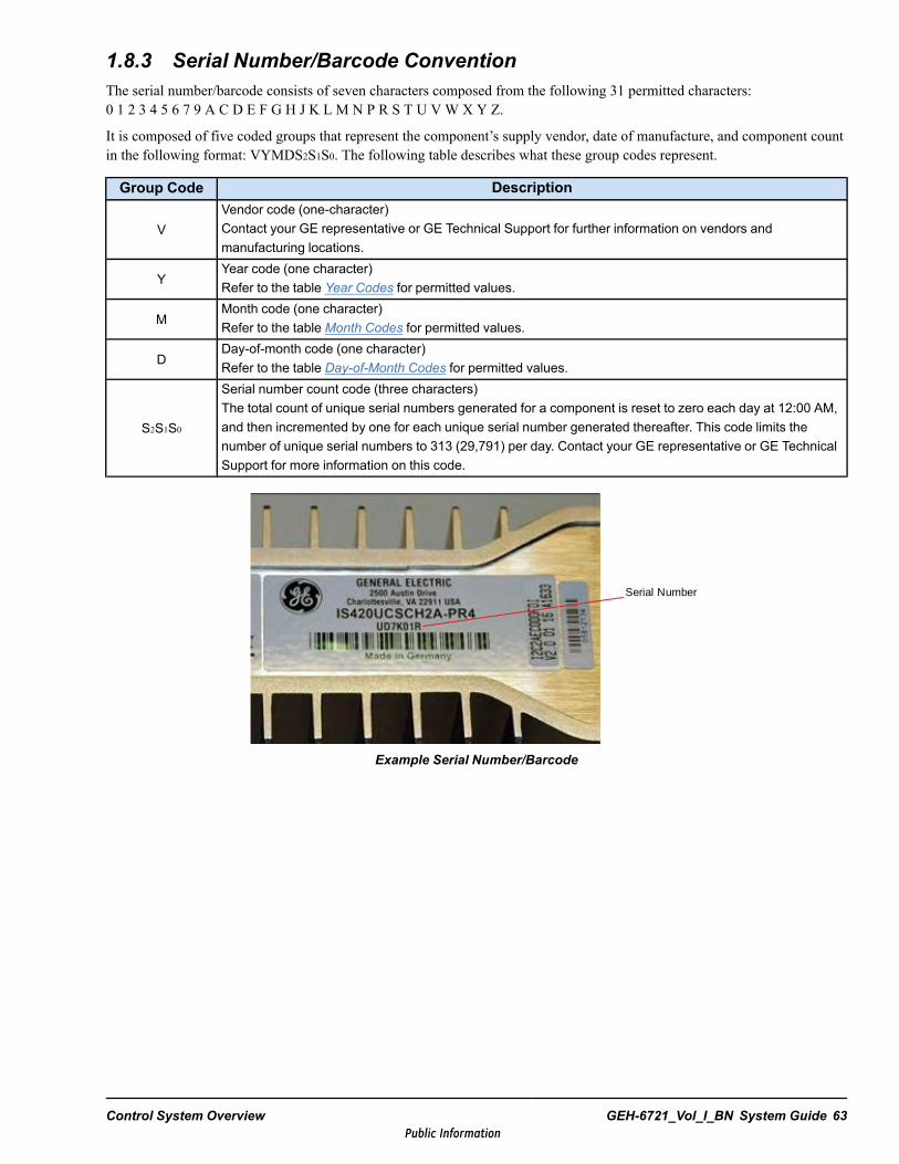
1.8.3 Serial Number/Barcode ConventionThe serial number/barcode consists of seven characters composed from the following 31 permitted characters:0 1 2 3 4 5 6 7 9 A C D E F G H J K L M N P R S T U VW X Y Z.
It is composed of five coded groups that represent the component’s supply vendor, date of manufacture, and component countin the following format: VYMDS2S1S0. The following table describes what these group codes represent.
Group Code Description
VVendor code (one-character)Contact your GE representative or GE Technical Support for further information on vendors andmanufacturing locations.
YYear code (one character)Refer to the table Year Codes for permitted values.
MMonth code (one character)Refer to the table Month Codes for permitted values.
DDay-of-month code (one character)Refer to the table Day-of-Month Codes for permitted values.
S2S1S0
Serial number count code (three characters)The total count of unique serial numbers generated for a component is reset to zero each day at 12:00 AM,and then incremented by one for each unique serial number generated thereafter. This code limits thenumber of unique serial numbers to 313 (29,791) per day. Contact your GE representative or GE TechnicalSupport for more information on this code.
Serial Number
Example Serial Number/Barcode
Control System Overview GEH-6721_Vol_I_BN System Guide 63Public Information
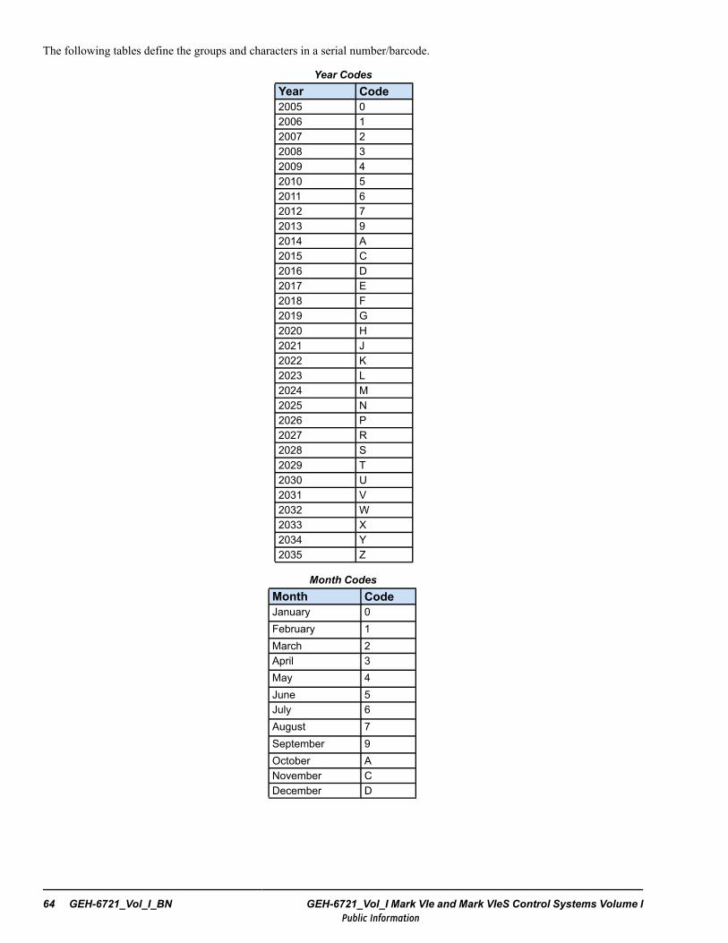
The following tables define the groups and characters in a serial number/barcode.
Year CodesYear Code2005 02006 12007 22008 32009 42010 52011 62012 72013 92014 A2015 C2016 D2017 E2018 F2019 G2020 H2021 J2022 K2023 L2024 M2025 N2026 P2027 R2028 S2029 T2030 U2031 V2032 W2033 X2034 Y2035 Z
Month CodesMonth CodeJanuary 0February 1March 2April 3May 4June 5July 6August 7September 9October ANovember CDecember D
64 GEH-6721_Vol_I_BN GEH-6721_Vol_I Mark VIe and Mark VIeS Control Systems Volume IPublic Information
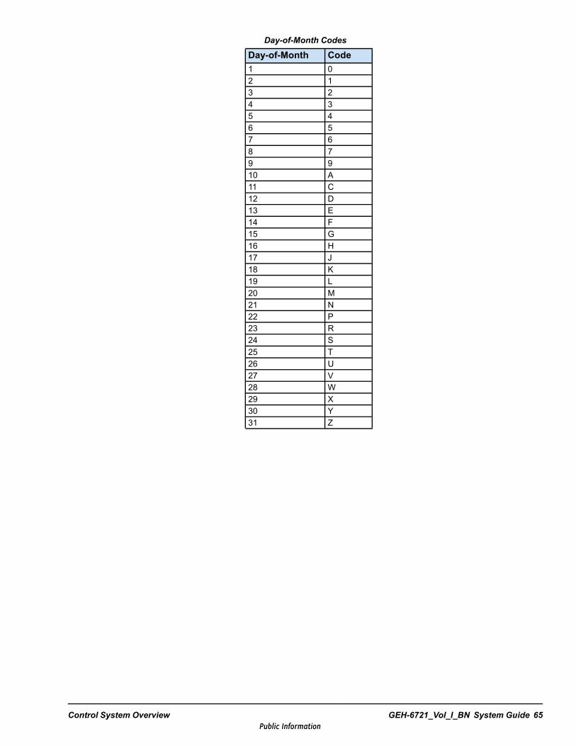
Day-of-Month Codes
Day-of-Month Code1 02 13 24 35 46 57 68 79 910 A11 C12 D13 E14 F15 G16 H17 J18 K19 L20 M21 N22 P23 R24 S25 T26 U27 V28 W29 X30 Y31 Z
Control System Overview GEH-6721_Vol_I_BN System Guide 65Public Information

Notes
66 GEH-6721_Vol_I_BN GEH-6721_Vol_I Mark VIe and Mark VIeS Control Systems Volume IPublic Information
2 Functional SafetyThis chapter provides an introduction to the Mark VIeS Safety control, which is usedfor functional safety loops to achieve SIL 2 and 3 capabilities. The Mark VIeS Safetycontrol is used by operators knowledgeable in safety-instrumented system (SIS)applications to reduce risk in critical safety functions. Safety controllers and distributedI/O modules are programmed specifically for safety control use, and this specificcontrol hardware has been IEC 61508 certified.
Functional safety is concerned about the speed of the control system’s reaction to tripthe system (energize to trip) or to provide an emergency shut-down (de-energize to trip)when a safety-critical event occurs. With this in mind, safety equipment is rated to meetsafety integrity levels (SIL), which are achieved by analyzing probability of failure ondemand.
The Mark VIeS Safety control is a differentiator in the market because of its significantflexibility, easy of control logic development, and redundancy capabilities. Its safetyI/O is very flexible in application, for example both analog inputs and outputs areavailable. The Mark VIeS Safety control is an engineered solution designed for thecustomers that work on our systems to help simplify and reduce maintenance costs.
GE has engineered specific solutions for their internal turbine power plant applications,meeting high standards for reliability of function, and continues to invest in new SILcapabilities, for example GE Oil & Gas YSIL applications. The Mark VIeS control hasjust recently been made available for integration into other safety-critical applicationsoutside of GE, for example emergency shutdown, burner management, and fire andgas-critical control applications. This solution reflects the experience of three plusdecades, four generations, and over ten thousand installed triple-redundant digitalturbine controls.
Functional Safety GEH-6721_Vol_I_BN System Guide 67Public Information
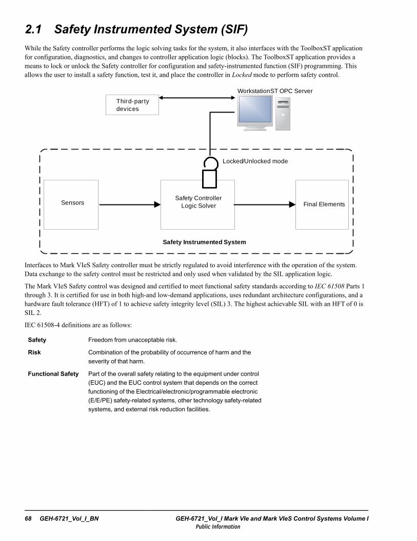
2.1 Safety Instrumented System (SIF)While the Safety controller performs the logic solving tasks for the system, it also interfaces with the ToolboxST applicationfor configuration, diagnostics, and changes to controller application logic (blocks). The ToolboxST application provides ameans to lock or unlock the Safety controller for configuration and safety-instrumented function (SIF) programming. Thisallows the user to install a safety function, test it, and place the controller in Locked mode to perform safety control.
SensorsSafety Controller
Logic Solver Final Elements
Safety Instrumented System
Third-party devices
WorkstationST OPC Server
Locked/Unlocked mode
Interfaces to Mark VIeS Safety controller must be strictly regulated to avoid interference with the operation of the system.Data exchange to the safety control must be restricted and only used when validated by the SIL application logic.
The Mark VIeS Safety control was designed and certified to meet functional safety standards according to IEC 61508 Parts 1through 3. It is certified for use in both high-and low-demand applications, uses redundant architecture configurations, and ahardware fault tolerance (HFT) of 1 to achieve safety integrity level (SIL) 3. The highest achievable SIL with an HFT of 0 isSIL 2.
IEC 61508-4 definitions are as follows:
Safety Freedom from unacceptable risk.
Risk Combination of the probability of occurrence of harm and theseverity of that harm.
Functional Safety Part of the overall safety relating to the equipment under control(EUC) and the EUC control system that depends on the correctfunctioning of the Electrical/electronic/programmable electronic(E/E/PE) safety-related systems, other technology safety-relatedsystems, and external risk reduction facilities.
68 GEH-6721_Vol_I_BN GEH-6721_Vol_I Mark VIe and Mark VIeS Control Systems Volume IPublic Information
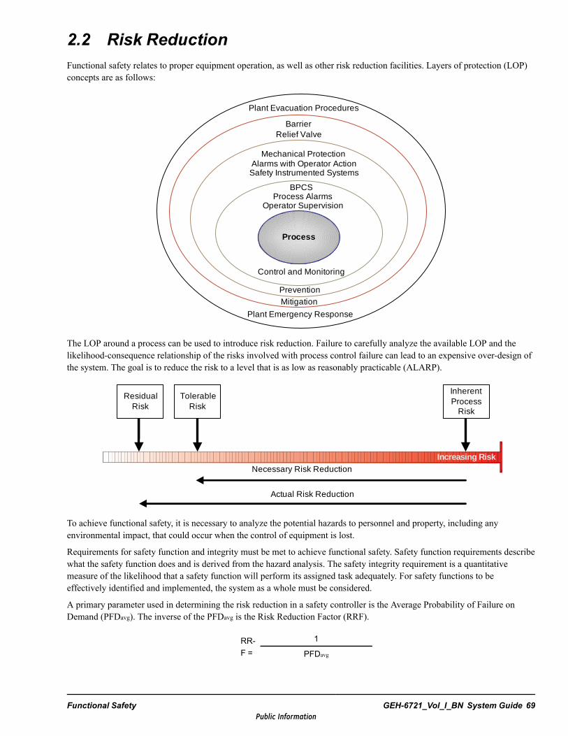
2.2 Risk ReductionFunctional safety relates to proper equipment operation, as well as other risk reduction facilities. Layers of protection (LOP)concepts are as follows:
Control and Monitoring
PreventionMitigation
Plant Emergency Response
BPCSProcess Alarms
Operator Supervision
Mechanical ProtectionAlarms with Operator ActionSafety Instrumented Systems
Plant Evacuation Procedures
Relief ValveBarrier
Process
The LOP around a process can be used to introduce risk reduction. Failure to carefully analyze the available LOP and thelikelihood-consequence relationship of the risks involved with process control failure can lead to an expensive over-design ofthe system. The goal is to reduce the risk to a level that is as low as reasonably practicable (ALARP).
Residual
Risk
Tolerable
Risk
InherentProcess
Risk
Necessary Risk Reduction
Actual Risk Reduction
Increasing Risk
Residual Risk
Tolerable Risk
Inherent Process
Risk
Necessary Risk Reduction
Actual Risk Reduction
To achieve functional safety, it is necessary to analyze the potential hazards to personnel and property, including anyenvironmental impact, that could occur when the control of equipment is lost.
Requirements for safety function and integrity must be met to achieve functional safety. Safety function requirements describewhat the safety function does and is derived from the hazard analysis. The safety integrity requirement is a quantitativemeasure of the likelihood that a safety function will perform its assigned task adequately. For safety functions to beeffectively identified and implemented, the system as a whole must be considered.
A primary parameter used in determining the risk reduction in a safety controller is the Average Probability of Failure onDemand (PFDavg). The inverse of the PFDavg is the Risk Reduction Factor (RRF).
RR-F =
1
PFDavg
Functional Safety GEH-6721_Vol_I_BN System Guide 69Public Information
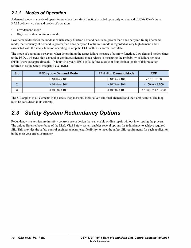
2.2.1 Modes of OperationA demand mode is a mode of operation in which the safety function is called upon only on demand. IEC 61508-4 clause3.5.12 defines two demand modes of operation:
• Low demand mode• High demand or continuous mode
Low demand describes the mode in which safety function demand occurs no greater than once per year. In high demandmode, the frequency of demand is greater than once per year. Continuous mode is regarded as very high demand and isassociated with the safety function operating to keep the EUC within its normal safe state.
The mode of operation is relevant when determining the target failure measure of a safety function. Low demand mode relatesto the PFDavg whereas high demand or continuous demand mode relates to measuring the probability of failure per hour(PFH) (there are approximately 104 hours in a year). IEC 61508 defines a scale of four distinct levels of risk reductionreferred to as the Safety Integrity Level (SIL).
SIL PFDavg Low Demand Mode PFH High Demand Mode RRF
1 ≥ 10-2 to < 10-1 ≥ 10-6 to < 10-5 > 10 to ≤ 100
2 ≥ 10-3 to < 10-2 ≥ 10-7 to < 10-6 > 100 to ≤ 1,000
3 ≥ 10-4 to < 10-3 ≥ 10-8 to < 10-7 > 1,000 to ≤ 10,000
The SIL applies to all elements in the safety loop (sensors, logic solver, and final element) and their architecture. The loopmust be considered in its entirety.
2.3 Safety System Redundancy OptionsRedundancy is a key feature in safety control system design that can enable on-line repair without interrupting the process.The unique Ethernet back-bone of the Mark VIeS Safety system enables several options for redundancy to achieve requiredSIL. This provides the safety control engineer unparalleled flexibility to meet the safety SIL requirements for each applicationin the most cost effective manner.
70 GEH-6721_Vol_I_BN GEH-6721_Vol_I Mark VIe and Mark VIeS Control Systems Volume IPublic Information
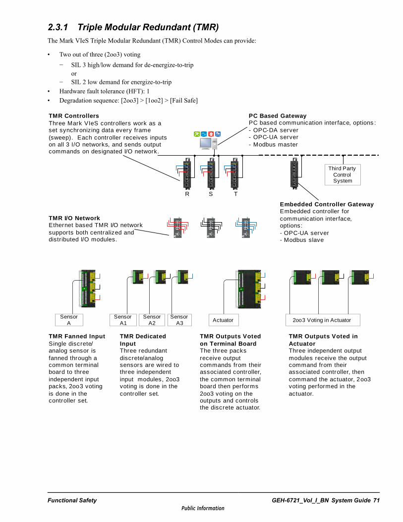
2.3.1 Triple Modular Redundant (TMR)The Mark VIeS Triple Modular Redundant (TMR) Control Modes can provide:
• Two out of three (2oo3) voting− SIL 3 high/low demand for de-energize-to-trip
or− SIL 2 low demand for energize-to-trip
• Hardware fault tolerance (HFT): 1• Degradation sequence: [2oo3] > [1oo2] > [Fail Safe]
TMR Fanned InputSingle discrete/analog sensor is fanned through a common terminal board to three independent input packs, 2oo3 voting is done in the controller set.
TMR Dedicated InputThree redundant discrete/analog sensors are wired to three independent input modules, 2oo3 voting is done in the controller set.
Sensor A
Sensor A1
Sensor A2
Sensor A3 Actuator
TMR Outputs Voted on Terminal BoardThe three packs receive output commands from their associated controller, the common terminal board then performs 2oo3 voting on the outputs and controls the discrete actuator.
2oo3 Voting in Actuator
TMR Outputs Voted in ActuatorThree independent output modules receive the output command from their associated controller, then command the actuator, 2oo3 voting performed in the actuator.
TMR ControllersThree Mark VIeS controllers work as a set synchronizing data every frame (sweep). Each controller receives inputs on all 3 I/O networks, and sends output commands on designated I/O network.
TMR I/O NetworkEthernet based TMR I/O network supports both centralized and distributed I/O modules.
R S T
Embedded Controller GatewayEmbedded controller for communication interface, options:- OPC-UA server- Modbus slave
Third Party Control System
PC Based GatewayPC based communication interface, options :- OPC-DA server- OPC-UA server- Modbus master
Functional Safety GEH-6721_Vol_I_BN System Guide 71Public Information

2.3.2 DualThe Mark VIeS Dual Control Modes can provide:
• One out of two (1oo2) voting, SIL 3 high/low demand for de-energize-to-trip• Two out of two (2oo2) voting, SIL 2 low demand for energize and de-energize-to-trip• Hardware fault tolerance (HFT): 1
TMR Fanned InputSingle sensor is fanned through a common terminal board to three independent input packs, 2oo3 voting done in the controller set.
Single SensorSingle sensor wired to a single input module with dual I/O network to controller set.
Sensor A
Sensor A
Sensor A1
Sensor A2
Actuator
TMR Outputs Voted on Terminal BoardThe three output packs receive an output command from designated controller, the common terminal board then performs 2oo3 voting and controls the actuator.
Acutator
1oo2 De-energize to Trip in Output ModulesTwo independent output modules receive the output command from designated controller, combination of two creates 1oo2 de-energize to tr ip function across the two modules.
Dual ControllersDual Mark VIeS controllers work as a controller set synchronizing data every frame (sweep). Each controller receives inputs on both I/O networks, and sends output commands on designated I/O network.
Dual I/O NetworkEthernet based dual I/O network supports both centralized and distributed I/O modules.
Dual SensorDual sensors wired to independent input modules with independent I/O networks to controller set.
Third Party Control System
R S
PC Based GatewayPC based communication interface, options:- OPC-DA server- OPC-UA server- Modbus master
Embedded Controller GatewayEmbedded controller for communication interface, options:- OPC-UA server- Modbus slave
72 GEH-6721_Vol_I_BN GEH-6721_Vol_I Mark VIe and Mark VIeS Control Systems Volume IPublic Information
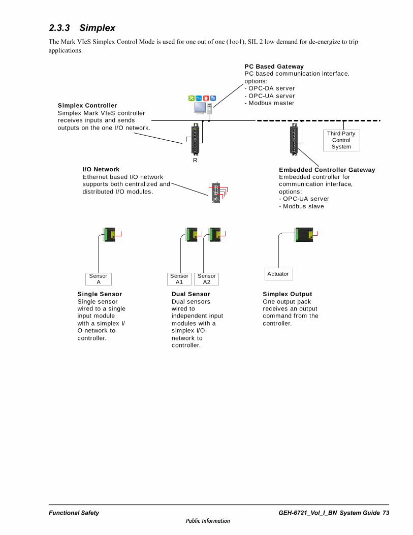
2.3.3 SimplexThe Mark VIeS Simplex Control Mode is used for one out of one (1oo1), SIL 2 low demand for de-energize to tripapplications.
R
Simplex ControllerSimplex Mark VIeS controller receives inputs and sends outputs on the one I/O network.
I/O NetworkEthernet based I/O network supports both centralized and distributed I/O modules.
PC Based GatewayPC based communication interface, options:- OPC-DA server- OPC-UA server- Modbus master
Third Party Control System
Embedded Controller GatewayEmbedded controller for communication interface, options:- OPC-UA server- Modbus slave
Single SensorSingle sensor wired to a single input module with a simplex I/O network to controller.
Sensor A
Sensor A1
Sensor A2
Dual SensorDual sensors wired to independent input modules with a simplex I/O network to controller.
Actuator
Simplex OutputOne output pack receives an output command from the controller.
Functional Safety GEH-6721_Vol_I_BN System Guide 73Public Information

Notes
74 GEH-6721_Vol_I_BN GEH-6721_Vol_I Mark VIe and Mark VIeS Control Systems Volume IPublic Information

3 Ethernet Networks3.1 IntroductionThe integrated control system is based on a hierarchy of Ethernet networks, used to interconnect individual nodes or zones.These networks separate the different communication traffic into layers according to their individual functions. This hierarchyextends from the I/O modules and controllers (providing real-time control of the process) to the HMIs, and out tofacility-wide monitoring and external networks (industrial internet).
Each network layer uses industry standard components and protocols to simplify integration between different platforms andimprove overall reliability and maintenance. These layers are designated as IONet, Unit Control, Supervisory, and Enterprisein the following figure, which displays a simplified network hierarchy and is not representative of any specific installation.
Ethernet Networks GEH-6721_Vol_I_BN System Guide 75Public Information
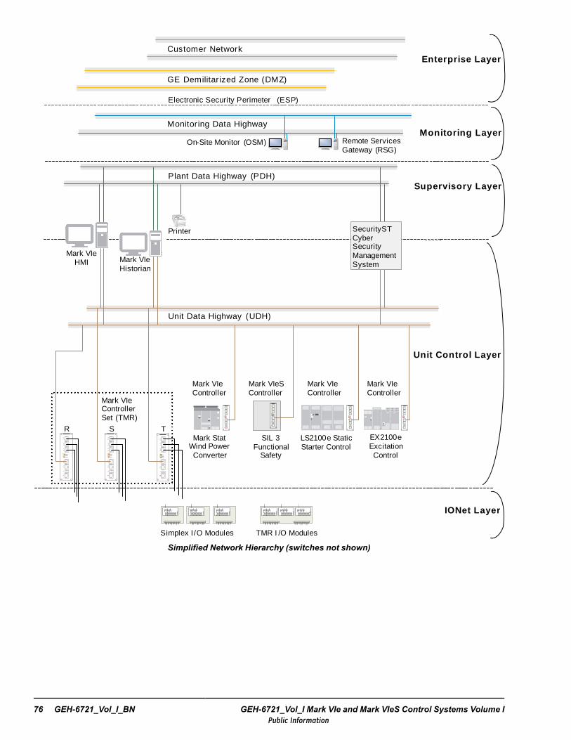
Mark VIe Controller Set (TMR)
Unit Control Layer
Supervisory Layer
Mark VIeS Controller
IONet Layer
EX2100e Excitation Control
LS2100e Static Starter Control
Mark VIe Controller
Mark VIe Controller
Plant Data Highway (PDH)
Unit Data Highway (UDH)
Enterprise Layer
GE Demilitarized Zone (DMZ)
Electronic Security Perimeter (ESP)
Mark Stat Wind Power Converter
Mark VIe Controller
R S T
TMR I /O ModulesSimplex I /O Modules
SIL 3 Functional
Safety
Monitoring Data HighwayMonitoring Layer
On-Site Monitor (OSM) Remote Services Gateway (RSG)
Mark VIe HMI Mark VIe
Historian
SecurityST Cyber Security Management System
Printer
Customer Network
Simplified Network Hierarchy (switches not shown)
76 GEH-6721_Vol_I_BN GEH-6721_Vol_I Mark VIe and Mark VIeS Control Systems Volume IPublic Information

3.1.1 GE Large Industrial Plant Network ArchitectureThe current networking architecture for GE large industrial plants uses a mesh architecture design (also known as hub andspoke) with redundant network switches. This design enables flexibility for implementation of cyber security offerings,allowing secure access to unit control data from external customer and monitoring networks. Trunks from the root or hubswitches to the edge or spoke switches shall be single-mode fiber for all new site installations. These trunks are configured toprovide the UDH, PDH, Monitoring Data Highway (MDH), and can also provide other optional networks to further partitionnetwork access to specified unit control equipment and data.
Network security can be implemented by adding an additional layer 3 security hardware infrastructure. Network traffic is thenregulated by an additional series of routers, switches, and firewalls. The SecurityST* appliance can be installed to allow fortighter network security with or without the additional layer 3 security hardware by providing white listing and restrictedaccess to network devices. Various options for existing sites are available to improve network security without having torelocate equipment or cable runs.
In the following figure, both cyber security offerings (the layer 3 hardware and the SecurityST server) are displayed as asimplified example that is not representative of any specific installation. This industrial plant network architecture providesflexibility to cost for sites with various security compliance requirements. A qualified GE networking engineer can determinebest fit options for particular customer facilities.
Ethernet Networks GEH-6721_Vol_I_BN System Guide 77Public Information
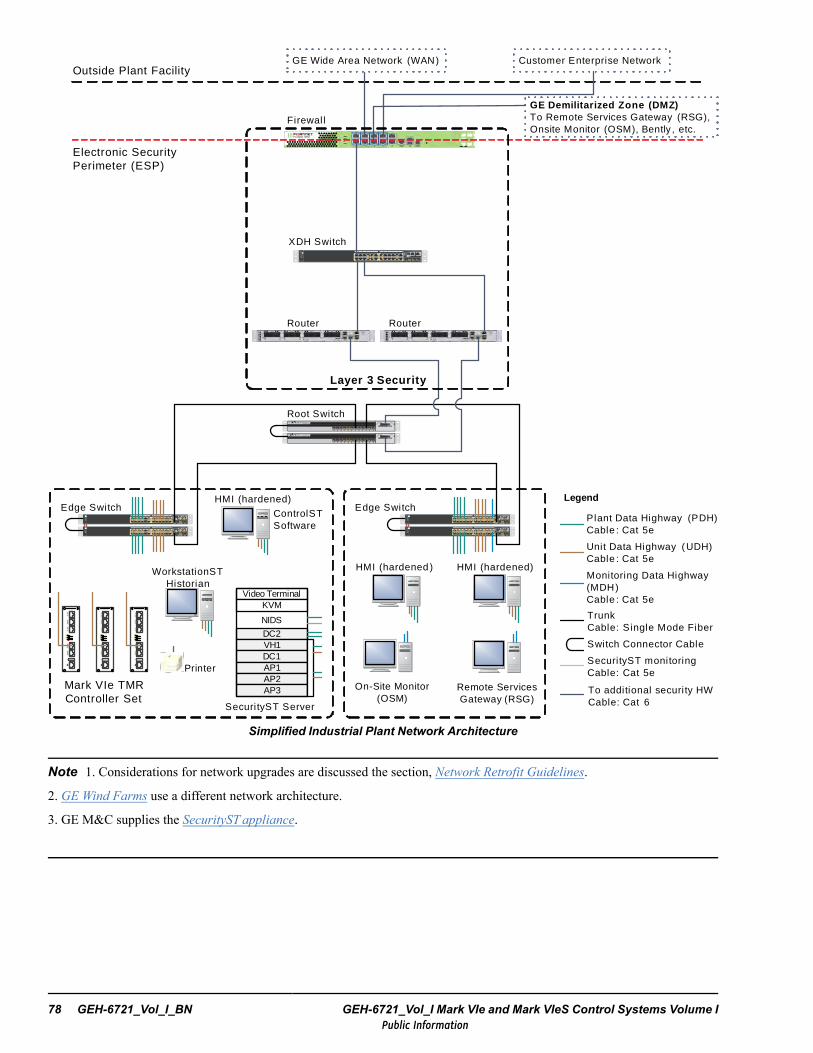
Securi tyST Server
Electronic Security Perimeter (ESP)
HMI (hardened)
Catalyst 2960-S Series
25 26 27 28
MGMT
BASET
CONSOLE
STCKSPEDDPLXSTATMSTR
RPSSYST
MODE
13X
14X
23X
24X
13 14 15 16 17 18 19 20 21 22 23 241 2 3 4 5 6 7 8 9 10 11 12
1X
2X
11X
12X
Catalyst 2960-S Series
25 26 27 28
MGMT
BASET
CONSOLE
STCKSPEDDPLXSTATMSTR
RPSSYST
MODE
13X
14X
23X
24X
13 14 15 16 17 18 19 20 21 22 23 241 2 3 4 5 6 7 8 9 10 11 12
1X
2X
11X
12X
Root SwitchMODE
Catalyst 3750 -X Series
BLAN KMODULEF N
SYSTCONS OLE XPS STAT SPEED DUPLX
S-PWR M AST STACK
Catalyst 3750-X Series
1 2 3 4 5 6 7 8 9 10 11 12
MODE
Catalyst 3750 -X Series
BLAN KMODULEF N
SYSTCONS OLE XPS STAT SPEED DUPLX
S-PWR M AST STACK
Catalyst 3750-X Series
1 2 3 4 5 6 7 8 9 10 11 12
ControlST Software
Mark VIe TMR Controller Set
Catalyst 2960-S Series
25 26 27 28
MGMT
BASET
CONSOLE
STCKSPEDDPLXSTATMSTR
RPSSYST
MODE
13 X
14 X
23X
24X
13 14 15 16 17 18 19 20 21 22 23 241 2 3 4 5 6 7 8 9 10 11 12
1X
2X
1 1X
1 2X
XDH Switch
Customer Enterprise NetworkGE Wide Area Network (WAN)
Firewall
Outside Plant Facility
GE Demilitarized Zone (DMZ)To Remote Services Gateway (RSG), Onsite Monitor (OSM), Bently , etc.
Layer 3 Security
Video TerminalKVM
DC2VH1DC1AP1AP2AP3
Catalyst 2960-S Series
25 26 27 28
MGMT
BASET
CONSOLE
STCKSPEDDPLXSTATMSTR
RPSSYST
MODE
13X
14X
23X
24X
13 14 15 16 17 18 19 20 21 22 23 241 2 3 4 5 6 7 8 9 10 11 12
1X
2X
11X
12X
Catalyst 2960-S Series
25 26 27 28
MGMT
BASET
CONSOLE
STCKSPEDDPLXSTATMSTR
RPSSYST
MODE
13X
14X
23X
24X
13 14 15 16 17 18 19 20 21 22 23 241 2 3 4 5 6 7 8 9 10 11 12
1X
2X
11X
12X
Edge Switch Edge Switch
Router Router
Switch Connector Cable
Plant Data Highway (PDH)Cable : Cat 5e
Legend
Unit Data Highway (UDH)Cable : Cat 5e
TrunkCable: Single Mode Fiber
To additional securi ty HWCable: Cat 6
WorkstationST Historian
HMI (hardened)
NIDS
SecurityST monitoringCable: Cat 5e
Monitoring Data Highway (MDH)Cable : Cat 5e
Printer
Remote Services Gateway (RSG)
On-Site Monitor (OSM)
HMI (hardened )
Simplified Industrial Plant Network Architecture
Note 1. Considerations for network upgrades are discussed the section, Network Retrofit Guidelines.
2. GE Wind Farms use a different network architecture.
3. GE M&C supplies the SecurityST appliance.
78 GEH-6721_Vol_I_BN GEH-6721_Vol_I Mark VIe and Mark VIeS Control Systems Volume IPublic Information
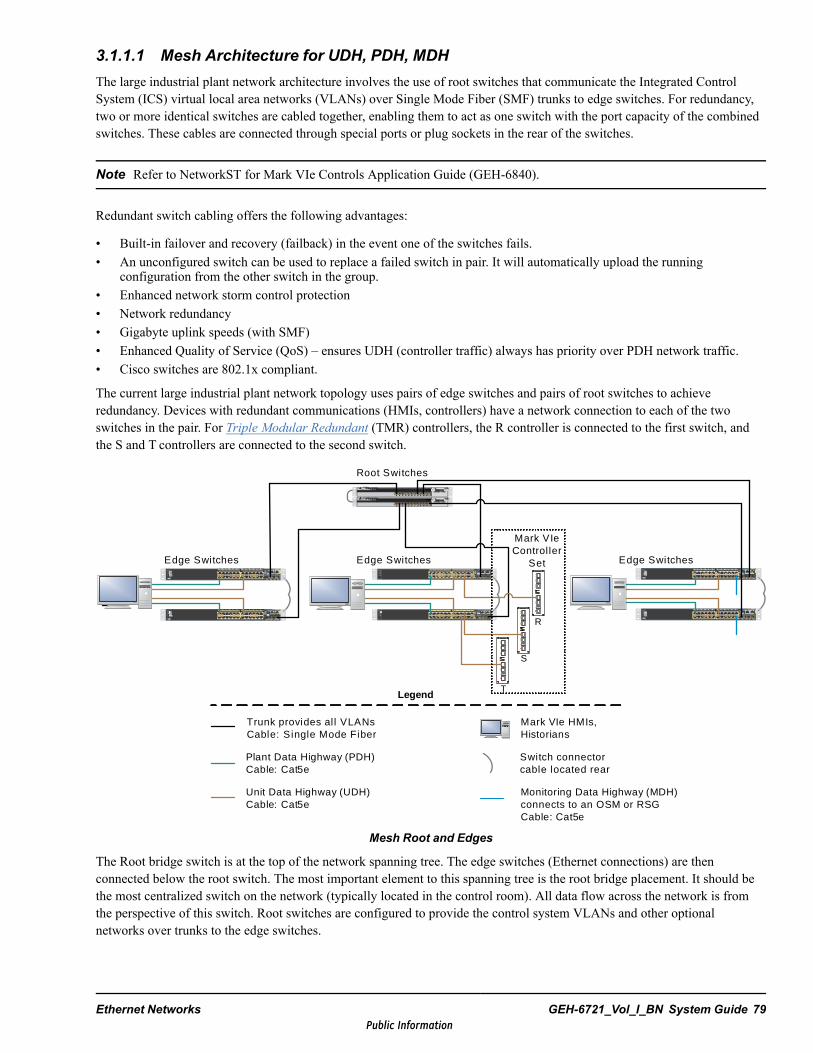
3.1.1.1 Mesh Architecture for UDH, PDH, MDHThe large industrial plant network architecture involves the use of root switches that communicate the Integrated ControlSystem (ICS) virtual local area networks (VLANs) over Single Mode Fiber (SMF) trunks to edge switches. For redundancy,two or more identical switches are cabled together, enabling them to act as one switch with the port capacity of the combinedswitches. These cables are connected through special ports or plug sockets in the rear of the switches.
Note Refer to NetworkST for Mark VIe Controls Application Guide (GEH-6840).
Redundant switch cabling offers the following advantages:
• Built-in failover and recovery (failback) in the event one of the switches fails.• An unconfigured switch can be used to replace a failed switch in pair. It will automatically upload the running
configuration from the other switch in the group.• Enhanced network storm control protection• Network redundancy• Gigabyte uplink speeds (with SMF)• Enhanced Quality of Service (QoS) – ensures UDH (controller traffic) always has priority over PDH network traffic.• Cisco switches are 802.1x compliant.
The current large industrial plant network topology uses pairs of edge switches and pairs of root switches to achieveredundancy. Devices with redundant communications (HMIs, controllers) have a network connection to each of the twoswitches in the pair. For Triple Modular Redundant (TMR) controllers, the R controller is connected to the first switch, andthe S and T controllers are connected to the second switch.
MODE Cat alyst 3750- X Ser iesBLANKMODULEFNSYSTCONSOLEXPSSTATSPEEDDUPLXS-PWRMASTSTACKCatalyst 3750-X Ser ies
1 2 3 4 5 6 7 8 9 10 11 12
MODE Cat alyst 3750- X Ser iesBLANKMODULEFNSYSTCONSOLEXPSSTATSPEEDDUPLXS-PWRMASTSTACKCatalyst 3750-X Ser ies
1 2 3 4 5 6 7 8 9 10 11 12
Root Switches
Edge Switches
Switch connector cable located rear
Mark VIe HMIs, Historians
Legend
Cat alyst 2960-S Ser ies
25 26 27 28
MGMTBASET
CONSOLE
STCKSPEDDPLXSTATMSTRRPSSYST
MODE
13X
14X
23X
24X
13 14 15 16 17 1819 20 21 22 23 241 2 3 4 5 6 7 8 9 10 11 12
1X
2X
11X
12X
Cat alyst 2960-S Ser ies
25 26 27 28
MGMTBASET
CONSOLE
STCKSPEDDPLXSTATMSTRRPSSYST
MODE
13X
14X
23X
24X
13 14 15 16 17 1819 20 21 22 23 241 2 3 4 5 6 7 8 9 10 11 12
1X
2X
11X
12X
Catalyst 2960-S Series
25 26 27 28
MGMT
BASET
CONSOLE
STCKSPEDDPLXSTATMSTRRPS
SYST
MODE
13X
14X
23X
24X
13 14 15 16 17 18 19 20 21 22 23 241 2 3 4 5 6 7 8 9 10 11 12
1X
2X
11X
12X
Catalyst 2960-S Series
25 26 27 28
MGMT
BASET
CONSOLE
STCKSPEDDPLXSTATMSTRRPS
SYST
MODE
13X
14X
23X
24X
13 14 15 16 17 18 19 20 21 22 23 241 2 3 4 5 6 7 8 9 10 11 12
1X
2X
11X
12X
Edge Switches
Mark VIe Controller
SetCat alyst 2960- S Series
25 26 27 28
MGMTBASET
CONSOLE
STCKSPEDDPLXSTATMSTRRPSSYST
MODE
13X
14X
23X
24X
13 1415 16 17 18 19 2021 22 23 241 2 3 4 5 6 7 8 9 10 11 12
1X
2X
11X
12X
Cat alyst 2960- S Series
25 26 27 28
MGMTBASET
CONSOLE
STCKSPEDDPLXSTATMSTRRPSSYST
MODE
13X
14X
23X
24X
13 1415 16 17 18 19 2021 22 23 241 2 3 4 5 6 7 8 9 10 11 12
1X
2X
11X
12X
Edge Switches
Trunk provides al l VLANsCable: Single Mode Fiber
Plant Data Highway (PDH)Cable: Cat5e
Unit Data Highway (UDH)Cable: Cat5e
Monitoring Data Highway (MDH) connects to an OSM or RSGCable: Cat5e
R
S
T
Mesh Root and Edges
The Root bridge switch is at the top of the network spanning tree. The edge switches (Ethernet connections) are thenconnected below the root switch. The most important element to this spanning tree is the root bridge placement. It should bethe most centralized switch on the network (typically located in the control room). All data flow across the network is fromthe perspective of this switch. Root switches are configured to provide the control system VLANs and other optionalnetworks over trunks to the edge switches.
Ethernet Networks GEH-6721_Vol_I_BN System Guide 79Public Information
Note Root and edge switches are not interchangeable.
Each edge switch connects back to a corresponding root bridge switch through the trunks. There is only one root bridgeswitch group in the system. Special configuration files define which switch acts as the root or edge. In addition, the edgeswitch ports are specially configured to provide the PDH, UDH, or MDH. Typically, ports 1–10 are PDH, ports 11–22 areUDH, and 23–24 are MDH (refer to the label on the switch itself for specific port details).
Depending on specific site network requirements, the Cisco 2960S can be supplied as a root bridge switch on jobs with up tofour units. Cisco 3750X switches serve as the root bridge at sites with more than four units.
3.2 IONet LayerIONet communication is internal between the controller(s) and the I/O modules through an unmanaged IONet switch. IONetredundancy can be one, two, or three networks, and is equal to the controller redundancy. The following cable color-codingfor RJ-45 hoods is used to reduce the chance for cross connecting:
Note On the UCSx controller from top to bottom, the networks are T, S, R.
• Blue for IONet 3 (T network)• Black for IONet 2 (S network)• Red for IONet 1 (R network)
Note Refer to the section Controller Redundancy for more information.
The IONet provides direct communication between controllers and I/O modules. IONet EGD protocol (which is different thanUDH EDG protocol) is used. The I/O modules send their inputs to the controllers and the controllers send their outputs to theI/O modules each frame, as displayed in the section Rate of Response. Examples of IONet traffic are as follows:
• Status of control system input data from the I/O packs to the controller set• Status of control system output data from the controller set to the I/O packs• I/O pack configuration data from the ToolboxST application to the controller to the I/O packs• I/O pack health status data from the packs to the controller• Field device input data from the I/O pack to the controller
Note The ESWx switch is used for IONet communication.
The sharing of input data between two control sets (Shared IONet) on a single IONet is available for the following controllers:
• One Mark VIeS Safety controller set and one Mark VIe controller set• One Mark Stat controller set and one Mark VIe controller set• Two Mark VIe controller sets
Note A control set is the group of controllers (based on redundancy) with the set of owned I/O modules. From theToolboxST System Editor Summary View, a control set displays as a single controller.
80 GEH-6721_Vol_I_BN GEH-6721_Vol_I Mark VIe and Mark VIeS Control Systems Volume IPublic Information

3.2.1 IONet SpecificationsIONets are IEEE 802.3 100 Megabits full duplex Ethernet networks. All traffic on each IONet is deterministic UDP/IP basedpackets. Each network (red, blue, black) is an independent IP subnet. The IEEE 1588 standard for precision clocksynchronization protocol is used to synchronize frame and time between the controllers, and the I/O modules on the IONet.This synchronization provides a high level of traffic flow control on the networks.
The following figure display maximum IONet cable lengths.
100FX FiberMulti mode (MMF): 2000 m (6600 ft)Single mode (SMF): 15km (9.32 miles)
Controller
Cat 5e (copper)
100m (328 ft) Cat 5e (copper )
100m (328 ft)
Copper or Fiber depending on distance required
field wir ing
Field device
Cat 5e (copper)
100m (328 ft)
IONet Maximum Distances
Item IONet SpecificationIEEE specification 802.3uWire speed 100 Mbps
Cable types 100Base-TX: UTP Cat 5e100Base-FX: MMF or SMF
Maximum taps per segment 2Maximum packets per network 199Maximum number of switches 5Topology Star
For the control system IONet topologies, the following rules apply for deploying SMF systems:
• No more than five switches can be placed in series between controller and remote I/O module.• The topology should be kept as flat and balanced as possible (star topology).
• Use the GE ESWA or ESWB switch with additional IR SFP single-mode transceiver for SFP1 and SFP2.− GE part # 65G2100-009 for single-mode fiber distances up to 2 km− GE part # 65G2100-008 for single-mode fiber distances up to 15 km
Caution
Use of any other switch in this application may cause miss operation and/or damage tothe associated equipment.
Ethernet Networks GEH-6721_Vol_I_BN System Guide 81Public Information

3.2.2 IONet SwitchesIONet switches are unmanaged, fully switched, and full-duplex to prevent collisions. They provide data buffering and flowcontrol during the critical input scan. Only industrial grade switches that meet the codes, standards, performance, andenvironmental criteria for industrial applications are used for the IONet. GE industrial Ethernet 10/100 IONet switches(ESWA and ESWB) have an operating temperature of -30 to 65°C (-22 to 149 °F), have provisions for redundant 18 to 36 Vdc power sources (200/400 mA), and can be DIN-rail mounted. The switches also provide LEDs to indicate the status of theIONet link, speed, activity, and duplex.
16-port ESWB IONet Switch
Caution
Use only GE-approved Ethernet switches in all control system I/O networks.Unsupported switches can prevent I/O modules from receiving controller outputs.
Approved IONet Switches
Part # DescriptionIS420ESWAH1A 8 ports 10/100BASE-TX + 1 port 100BASE-FX LC-type connection
IS420ESWAH2A 8 ports 10/100BASE-TX + 2 ports 100BASE-FX LC-type connection
IS420ESWAH3A 8 ports 10/100BASE-TX
IS420ESWAH4A 8 ports 10/100BASE-TX + 1 port 100BASE-LX10 LC-type connection
IS420ESWAH5A 8 ports 10/100BASE-TX + 2 ports 100BASE-LX10 LC-type connection
IS420ESWBH1A 16 ports 10/100BASE-TX + 1 port 100BASE-FX LC-type connection
IS420ESWBH2A 16 ports 10/100BASE-TX + 2 ports 100BASE-FX LC-type connection
IS420ESWBH3A 16 ports 10/100BASE-TX
IS420ESWBH4A 16 ports 10/100BASE-TX + 1 port 100BASE-LX10 LC-type connection
IS420ESWBH5A 16 ports 10/100BASE-TX + 2 ports 100BASE-LX10 LC-type connection
Part # Description336A4940DNP508TX 8 copper ports
336A4940DNP516TX 16 copper ports
336A4940DNP509FX 8 copper ports and 1 fiber port
336A4940DNP517FX 16 copper ports and 1 fiber port
336A4940DNP508FXE2 6 copper ports and 2 fiber ports (single mode)336A4940JEP001 Installed within the 1.x ESS wind turbine hub336A4940JEP002 Installed within the 1.x wind turbine top box
336A4940JEP003 Installed within the 1.x wind turbine Down Tower Assembly (DTA)336A4940JEP004 Installed within the 2.x and 1.x non-ESS wind turbine hub
82 GEH-6721_Vol_I_BN GEH-6721_Vol_I Mark VIe and Mark VIeS Control Systems Volume IPublic Information
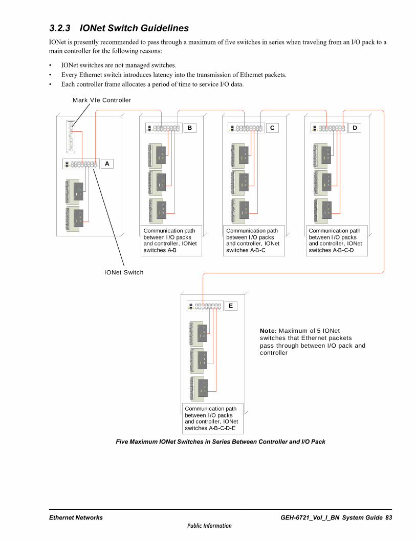
3.2.3 IONet Switch GuidelinesIONet is presently recommended to pass through a maximum of five switches in series when traveling from an I/O pack to amain controller for the following reasons:
• IONet switches are not managed switches.• Every Ethernet switch introduces latency into the transmission of Ethernet packets.• Each controller frame allocates a period of time to service I/O data.
Mark VIe Controller
IONet Switch
Communication path between I /O packs and controller, IONet switches A-B
A
B C D
E
Communication path between I /O packs and controller, IONet switches A-B-C
Communication path between I /O packs and controller, IONet switches A-B-C-D
Communication path between I /O packs and controller, IONet switches A-B-C-D-E
Note: Maximum of 5 IONet switches that Ethernet packets pass through between I/O pack and controller
Five Maximum IONet Switches in Series Between Controller and I/O Pack
Ethernet Networks GEH-6721_Vol_I_BN System Guide 83Public Information

3.2.4 I/O Pack Ethernet AddressingOn the IONet, I/O packs are assigned IP addresses through the DHCP servers in the controllers. The Host ID presented to theDHCP server is based on the board type and serial number information stored on a serial EEPROM located on the terminalboard. Since the Host ID is part of the terminal board, the I/O pack can be replaced without having to update the ToolboxSTapplication or controller communication IDs.
Note When a terminal board is replaced, the user must associate the new Host ID to the configured device. The ToolboxSTapplication presents a list of unrecognized devices that have requested IP addresses to simplify this process.
IONets are Class C networks. Each is an independent network with different subnet addresses. The IONet IP host addressesfor the controllers are fixed. The IP addresses of the I/O packs are assigned by the ToolboxST application, and the controllerautomatically distributes the addresses to the I/O packs through a standard Dynamic Host Configuration Protocol (DHCP)server in the controllers.
84 GEH-6721_Vol_I_BN GEH-6721_Vol_I Mark VIe and Mark VIeS Control Systems Volume IPublic Information
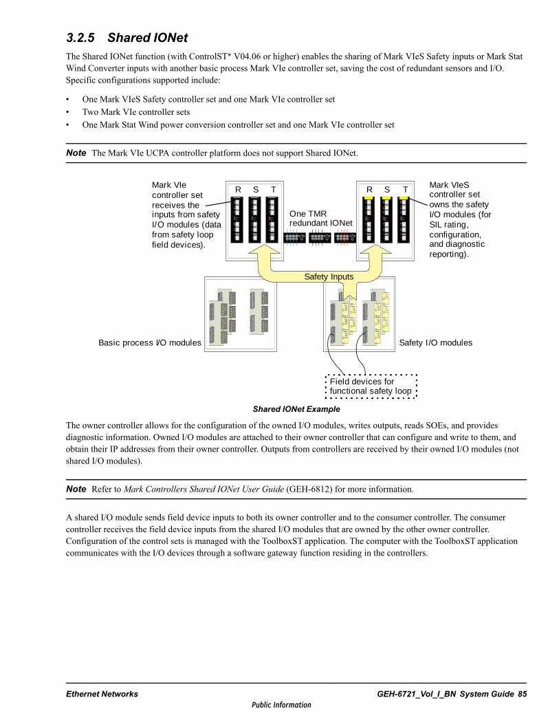
3.2.5 Shared IONetThe Shared IONet function (with ControlST* V04.06 or higher) enables the sharing of Mark VIeS Safety inputs or Mark StatWind Converter inputs with another basic process Mark VIe controller set, saving the cost of redundant sensors and I/O.Specific configurations supported include:
• One Mark VIeS Safety controller set and one Mark VIe controller set• Two Mark VIe controller sets• One Mark Stat Wind power conversion controller set and one Mark VIe controller set
Note The Mark VIe UCPA controller platform does not support Shared IONet.
R S T R S T
Safety Inputs
Field devices for functional safety loop
Mark VIeS controller set owns the safety I/O modules (for SIL rating, configuration, and diagnostic reporting).
Safety I/O modulesBasic process I/O modules
Mark VIe controller set receives the inputs from safety I/O modules (data from safety loop field devices).
One TMR redundant IONet
Shared IONet Example
The owner controller allows for the configuration of the owned I/O modules, writes outputs, reads SOEs, and providesdiagnostic information. Owned I/O modules are attached to their owner controller that can configure and write to them, andobtain their IP addresses from their owner controller. Outputs from controllers are received by their owned I/O modules (notshared I/O modules).
Note Refer to Mark Controllers Shared IONet User Guide (GEH-6812) for more information.
A shared I/O module sends field device inputs to both its owner controller and to the consumer controller. The consumercontroller receives the field device inputs from the shared I/O modules that are owned by the other owner controller.Configuration of the control sets is managed with the ToolboxST application. The computer with the ToolboxST applicationcommunicates with the I/O devices through a software gateway function residing in the controllers.
Ethernet Networks GEH-6721_Vol_I_BN System Guide 85Public Information
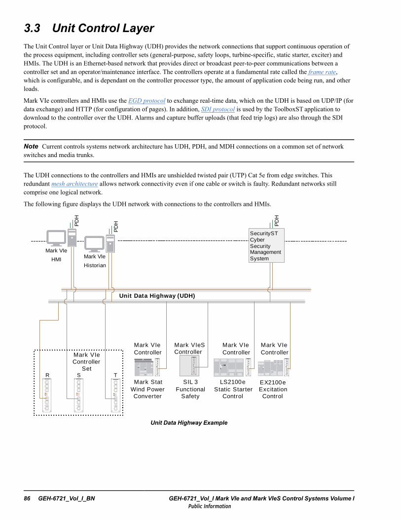
3.3 Unit Control LayerThe Unit Control layer or Unit Data Highway (UDH) provides the network connections that support continuous operation ofthe process equipment, including controller sets (general-purpose, safety loops, turbine-specific, static starter, exciter) andHMIs. The UDH is an Ethernet-based network that provides direct or broadcast peer-to-peer communications between acontroller set and an operator/maintenance interface. The controllers operate at a fundamental rate called the frame rate,which is configurable, and is dependant on the controller processor type, the amount of application code being run, and otherloads.
Mark VIe controllers and HMIs use the EGD protocol to exchange real-time data, which on the UDH is based on UDP/IP (fordata exchange) and HTTP (for configuration of pages). In addition, SDI protocol is used by the ToolboxST application todownload to the controller over the UDH. Alarms and capture buffer uploads (that feed trip logs) are also through the SDIprotocol.
Note Current controls systems network architecture has UDH, PDH, and MDH connections on a common set of networkswitches and media trunks.
The UDH connections to the controllers and HMIs are unshielded twisted pair (UTP) Cat 5e from edge switches. Thisredundant mesh architecture allows network connectivity even if one cable or switch is faulty. Redundant networks stillcomprise one logical network.
The following figure displays the UDH network with connections to the controllers and HMIs.
Mark VIe Controller
Set
Mark VIeS Controller
EX2100e Excitation
Control
LS2100e Static Starter
Control
Mark VIe Controller
Mark VIe Controller
Unit Data Highway (UDH)
Mark Stat Wind Power Converter
Mark VIe Controller
R S TSIL 3
Functional Safety
SecurityST Cyber Security Management System
PD
H
PD
H PD
H
Mark VIe
HMI Mark VIe
Historian
Unit Data Highway Example
86 GEH-6721_Vol_I_BN GEH-6721_Vol_I Mark VIe and Mark VIeS Control Systems Volume IPublic Information

3.3.1 UDH Communicator in a Redundant Controller SetIn dual or TMR Mark VIe controller sets, a single controller is designated to transmit real-time and alarm data for the set; thisis the UDH Communicator. This data includes both control signals (EGD) and alarms (SDI). Since each controller has anindependent, physical connection to the UDH, if a UDH network fault occurs where one controller becomes isolated from itscompanion controllers, the isolated controllers assumes the role of UDH communicator for that network fragment. For thisreason, a controller set has only one designated controller, while there could be multiple UDH communicators. Thedesignated controller is always a UDH communicator.
Note UDH command data is replicated to redundant controllers by the UDH Communicator, allowing for synchronizationacross the redundant controller set.
When a controller does not receive external EGD data from its UDH connection, it may request that the data be forwardedacross the IONet from another UDH communicator. One or more communicators supply the data, and the requestingcontroller uses the last data set received. Only the external EGD data used in sequencing by the controllers is forwarded inthis manner.
3.3.2 UDH Network Specifications
Item Description
Type of Network Ethernet, full duplex, in a single or redundant star configuration
Media and Distance Ethernet 100Base-TX for switch to controller/device connections. The cable is 22 to 26 AWGunshielded twisted pair; category 5e EIA/TIA 568 A/B. Distance is up to 100 m. Ethernet100Base-FX with fiber-optic cable optional for distances up to 2 km (1.24 mi).
Number of Nodes At least 25 nodes, given a 25 Hz data rate. Other configurations may be available.
Type of Nodes Supported Controllers, PLCs, operator interfaces, and engineering workstations
Protocol EGD, based on UDP/IP
Message Integrity 32-bit CRC appended to each Ethernet packet plus integrity checks built into UDP and EGD
Time Sync. Methods Network time protocol (NTP), accuracy ±1 ms.
3.3.3 Control System Devices on the UDH
3.3.3.1 Mark VIe ControllersThe Mark VIe controllers are applied in a wide variety of industrial control applications. The Mark VIeS Safety controller isused for safety-critical SIL applications. The Mark VIe UCPA platform is a lower cost, smaller footprint controller withintegral I/O and limited expansion I/O capability. The same ToolboxST application is used for configuration of the Mark VIecontroller product line. For more information, refer to Mark VIe and Mark VIeS Control Systems Volume II: System Guide forGeneral-purpose Applications (GEH-6721_Vol_II), the chapter Controllers.
The EX2100e excitation controller supplies dc power to the field of the synchronous generator, and controls the generator acterminal voltage and/or the reactive volt-amperes by means of the field current. The excitation control system is supplied inNEMA 1 freestanding floor-mounted indoor type metal cabinets. The cabinet lineup consists of several cabinets boltedtogether.
Note Refer to EX2100e Excitation Control User Guide (GEH-6781) for further details.
Ethernet Networks GEH-6721_Vol_I_BN System Guide 87Public Information

The LS2100e Static Starter controller is used to start a gas turbine by running the generator as a starting motor. The StaticStarter control, the Mark VIe control, and the excitation control system form an integrated static start system. The Mark VIecontrol supplies the run, torque, and speed setpoint signals to the Static Starter control, which operates in a closed loop controlmode to supply variable frequency power to the generator stator. The excitation control system is controlled by the StaticStarter control to regulate the field current during startup.
Note The Static Starter control cabinet is a ventilated NEMA 1 freestanding enclosure made of 12-gauge sheet steel on arigid steel frame designed for indoor mounting.
The LS2100e Static Starter control is an adjustable speed ac drive system specifically designed to start a gas turbine generatorset. By operating the generator as a synchronous motor, the static starter accelerates the turbine set according to a specificspeed profile that provides optimum starting conditions for the gas turbine. The LS2100e control eliminates the need forseparate starting hardware, such as an electric motor or diesel engine, torque converters, and associated auxiliary equipment,thus opening up critical space around the turbine base.
Note Refer to LS2100e Static Starter Control User Guide (GEH-6798).
The Mark Stat controller contains specialized firmware and application to control a GE multi-megawatt wind turbine powerconversion system.
3.3.3.2 Human-machine InterfaceThe Human-machine Interface (HMI) is the main operator interface to the Mark VIe control system. Current Mark VIe HMIsare desktop computers running the Windows® 7 operating system with multiple communication drivers for the redundant datahighways, WorkstationST* and ToolboxST applications, and the CIMPLICITYAdvanced Viewer for the Graphical UserInterface (GUI). The operator initiates commands from the real-time graphic displays, and views real-time process data andalarms. Detailed I/O diagnostics and system configuration is accomplished from the ToolboxST applications.
Note HMIs typically connect to both PDH and UDH networks.
The WorkstationST server is the hub of the system, channeling data between the UDH and the PDH, and providing datasupport and system management. The server also has the responsibility for device communication for both internal andexternal data interchanges. WorkstationST servers collect data on the UDH, and use the PDH to communicate with HMIviewers. Configuration servers, Historian servers, and Alarm servers are used for large system scaling. Multiple servers canbe used to provide redundancy so that communication with the viewers continues even if one server fails.
Note The HMI can be configured as a server or viewer, containing tools and utility programs.
88 GEH-6721_Vol_I_BN GEH-6721_Vol_I Mark VIe and Mark VIeS Control Systems Volume IPublic Information

3.3.3.3 HistorianThe Mark VIe Historian computer runs ControlST software including Historian reports, the WorkstationST application, andTrender, and can be configured for PI or Proficy data exchange to an external database server. The Historian is a data archivalsystem based on client-server technology, used for data collection, storage, and display of process data. Flexible tools enablethe operator to quickly generate custom trends and reports from the archived process data. The Historian combineshigh-resolution digital event data from the Mark VIe controllers with process analog data, creating a sophisticated tool forinvestigating cause-effect relationships.
The Historian receives data from the controllers over the UDH. The HMIs and other operator interface devices communicateto the Historian through the PDH. Network technology provided by the Windows operating system allows interaction fromnetwork computers, including query and view capabilities, using the Historian Client Tool Set. The interface options includethe ability to export data into spreadsheet applications.
3.3.3.4 Power Conversion ControllersGE Brilliance* solar inverter and legacy wind power conversion controllers can reside on the integrated control system UDH,and are configured with a common ToolboxST application.
3.3.4 Control Data Highway (CDH)A second UDH or redundant Ethernet Communication known as the Control Data Highway (CDH) allows two separatecontrollers to communicate with each other. The second CDH Ethernet can be added to a control system currently using theother UDH Ethernet port. The following table displays requirements for hardware setup.
Note To configure a CDH, refer to ToolboxST User Guide for Mark Controls Platform (GEH-6700 or GEH-6703), thesection Networks.
CDH Hardware Setup
FirstController
SecondController
Ethernet Connection
Simplex Simplex Each controller connects though the second Ethernet port using a single cross-overcategory 5 network cable.
Simplex Dual The simplex controller connects to the second Ethernet ports of both the <R> and <S>controllers of the dual system using a category 5 network cable through a networkswitch.
Simplex TMR The simplex controller connects to the second Ethernet ports of <R>, <S>, and <T>controllers of the TMR system using a category 5 network cable through a networkswitch.
Dual Dual The <R> and <S> controllers of each system connect using a category 5 networkcable through a network switch.
Dual TMR The <R> and <S> controllers of the dual system connect to the <R>, <S>, and <T>controllers of the TMR system using a category 5 network cable through a networkswitch.
TMR TMR The <R>, <S>, and <T> controllers of each system connect using a category 5network cable through a network switch.With the TMR and TMR configuration, the customer does not have to use the networkif all EGD exchanges run at frame rate.
Ethernet Networks GEH-6721_Vol_I_BN System Guide 89Public Information
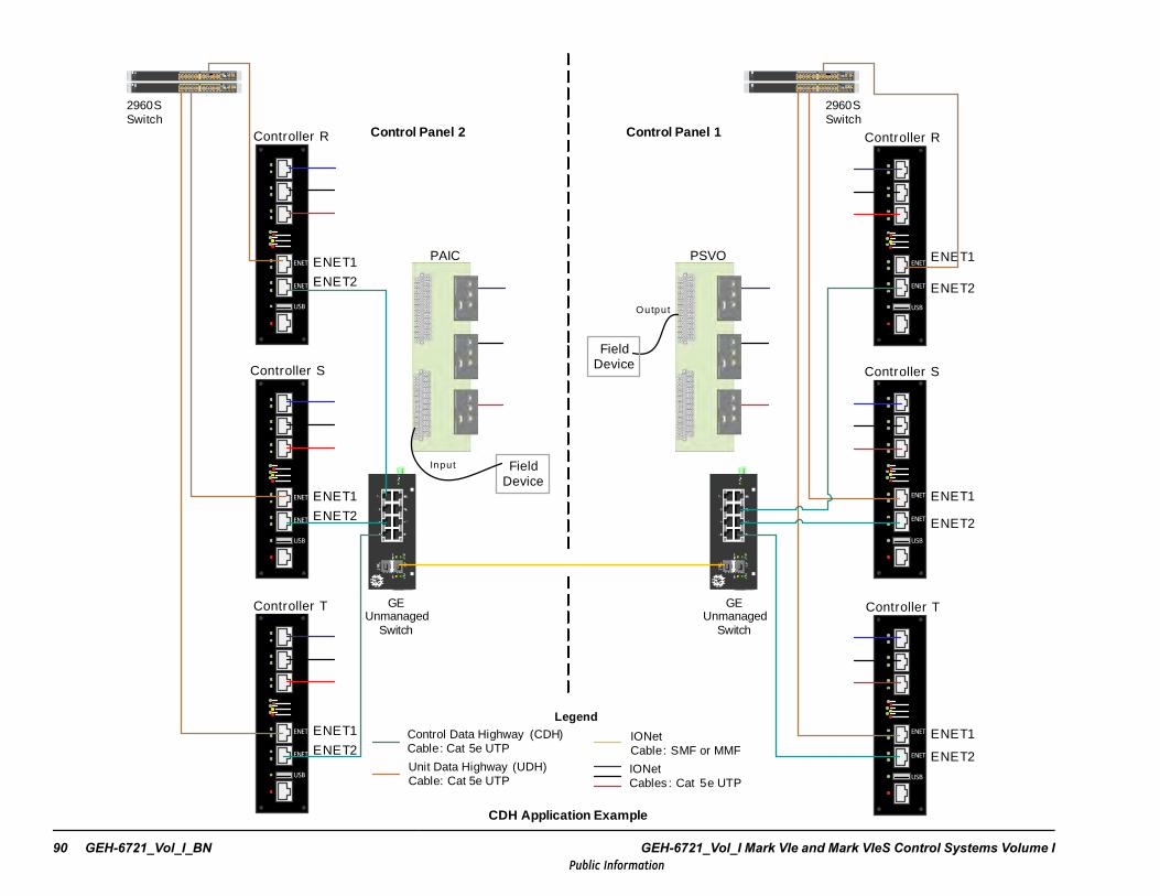
ENET1
ENET1
ENET1 ENET1
ENET1
ENET1
ENET2
ENET2
ENET2
ENET2
ENET2
C atalyst 2960-S Series
25 26 27 28
MGMT
BASET
CONSOLE
S TCKS PE DD PLX
S TATMSTR
R PS
S YS T
MODE
13X
14X
23X
24X
13 14 15 16 17 18 19 20 21 22 23 241 2 3 4 5 6 7 8 9 10 11 12
1X
2X
11X
12X
C atalyst 2960-S Series
25 26 27 28
MGMT
BASET
CONSOLE
S TCKS PE DD PLX
S TATMSTR
R PSS YS T
MODE
13X
14X
23X
24X
13 14 15 16 17 18 19 20 21 22 23 241 2 3 4 5 6 7 8 9 10 11 12
1X
2X
11X
12X
Controller R
Controller S
Controller T
2960S Switch
Control Panel 1Control Panel 2
PAIC PSVO
ENET2
GE Unmanaged
Switch
Field Device
Output
C atalys t 2960-S Series
25 26 27 28
MGMT
BASET
CONSOLE
STCKSPE DDPLX
STATMSTR
R PS
SYS T
MODE
13X
14X
23X
24X
13 14 15 16 17 18 19 20 21 22 23 241 2 3 4 5 6 7 8 9 10 11 12
1X
2X
11X
12X
C atalys t 2960-S Series
25 26 27 28
MGMT
BASET
CONSOLE
STCKSPE DDPLX
STATMSTR
R PSSYS T
MODE
13X
14X
23X
24X
13 14 15 16 17 18 19 20 21 22 23 241 2 3 4 5 6 7 8 9 10 11 12
1X
2X
11X
12X
Controller R
Controller S
Controller T
Input
2960S Switch
CDH Application Example
Control Data Highway (CDH)Cable: Cat 5e UTP
Legend
Unit Data Highway (UDH)Cable: Cat 5e UTP
IONetCables : Cat 5e UTP
IONetCable: SMF or MMF
Field Device
GE Unmanaged
Switch
90 GEH-6721_Vol_I_BN GEH-6721_Vol_I Mark VIe and Mark VIeS Control Systems Volume IPublic Information
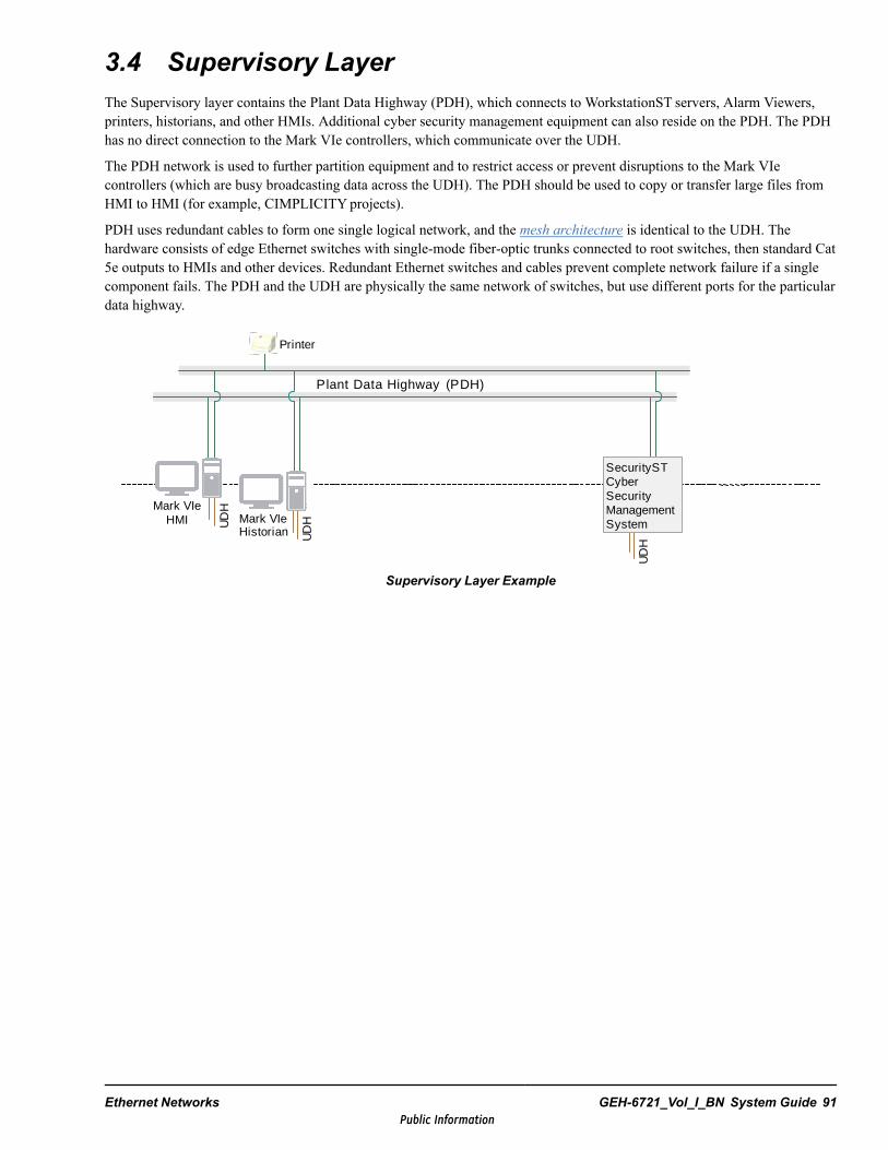
3.4 Supervisory LayerThe Supervisory layer contains the Plant Data Highway (PDH), which connects to WorkstationST servers, Alarm Viewers,printers, historians, and other HMIs. Additional cyber security management equipment can also reside on the PDH. The PDHhas no direct connection to the Mark VIe controllers, which communicate over the UDH.
The PDH network is used to further partition equipment and to restrict access or prevent disruptions to the Mark VIecontrollers (which are busy broadcasting data across the UDH). The PDH should be used to copy or transfer large files fromHMI to HMI (for example, CIMPLICITYprojects).
PDH uses redundant cables to form one single logical network, and the mesh architecture is identical to the UDH. Thehardware consists of edge Ethernet switches with single-mode fiber-optic trunks connected to root switches, then standard Cat5e outputs to HMIs and other devices. Redundant Ethernet switches and cables prevent complete network failure if a singlecomponent fails. The PDH and the UDH are physically the same network of switches, but use different ports for the particulardata highway.
Plant Data Highway (PDH)
UD
H
UD
H
UD
H
SecurityST Cyber Security Management System
Printer
Mark VIe HMI Mark VIe
Historian
Supervisory Layer Example
Ethernet Networks GEH-6721_Vol_I_BN System Guide 91Public Information
PDH Network FeaturesFeature DescriptionType of Network IEEE 802.3 Ethernet in a mesh topologySpeed 100 megabit per second or with 1000 megabit per second trunks interconnecting switches
Media and Distance
Ethernet 100Base-TX is used for switch to controller/device connections. Cable is CAT 5ecompliant. Distance is up to 100 m (328 ft). * Fiber-optic connections, Ethernet 100FX, 1000SX,1000 LX are used for distances of 2 km (1.24 mi), 550 m (1804.46 ft), and 5 km (3.11 mi),respectively.
Number of Nodes Up to 1024 nodes supported
ProtocolsEthernet-compatible protocol, typically TCP/IP-based. Use GSM, OPC UA, or Modbus overEthernet for external communications.
Message Integrity32-bit cyclic redundancy code (CRC) appended to each Ethernet packet plus additional checks inprotocol used.
External Interfaces Various third-party interfaces are available; GSM, OPC UA, and Modbus are the most common.* Fiber-optic cable provides the best signal quality, completely free of electromagnetic interference (EMI) and radio frequencyinterference (RFI). Large point-to-point distances are possible, and since the cable does not carry electrical charges, groundpotential problems are eliminated.
3.5 Monitoring LayerThe monitoring data highway (MDH) is used to further partition the flow of data to individual assets, and can includeconnection to GE Monitoring and Diagnostic (M&D) equipment: the On-Site Monitor (OSM) or Remote Services Gateway(RSG). The data that is allowed to travel over the MDH is managed by two specially configured Cisco 2901 routers. Thesame mesh architecture and trunks provide the MDH from the root to edge switches, then from special configured ports on theedge switches to the OSM or RSG. Other devices may also be included on the MDH to meet customer requirements.Connectivity to the RSG and OSM is designed during the plant requisition phase, so the MDH is not the only availableimplementation of GE M&D equipment.
Note Refer to the figure Simplified Network Hierarchy.
92 GEH-6721_Vol_I_BN GEH-6721_Vol_I Mark VIe and Mark VIeS Control Systems Volume IPublic Information
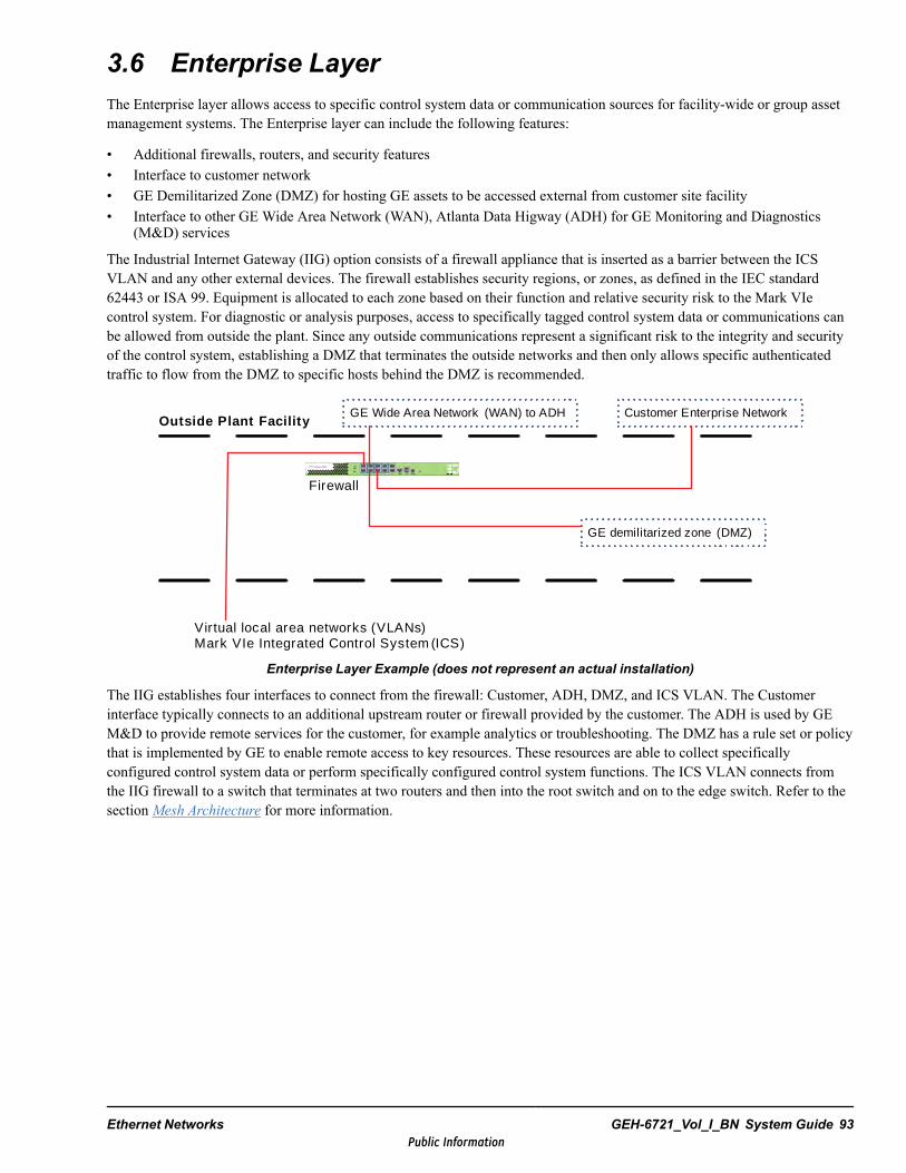
3.6 Enterprise LayerThe Enterprise layer allows access to specific control system data or communication sources for facility-wide or group assetmanagement systems. The Enterprise layer can include the following features:
• Additional firewalls, routers, and security features• Interface to customer network• GE Demilitarized Zone (DMZ) for hosting GE assets to be accessed external from customer site facility• Interface to other GE Wide Area Network (WAN), Atlanta Data Higway (ADH) for GE Monitoring and Diagnostics
(M&D) services
The Industrial Internet Gateway (IIG) option consists of a firewall appliance that is inserted as a barrier between the ICSVLAN and any other external devices. The firewall establishes security regions, or zones, as defined in the IEC standard62443 or ISA 99. Equipment is allocated to each zone based on their function and relative security risk to the Mark VIecontrol system. For diagnostic or analysis purposes, access to specifically tagged control system data or communications canbe allowed from outside the plant. Since any outside communications represent a significant risk to the integrity and securityof the control system, establishing a DMZ that terminates the outside networks and then only allows specific authenticatedtraffic to flow from the DMZ to specific hosts behind the DMZ is recommended.
GE demilitarized zone (DMZ)
Customer Enterprise NetworkGE Wide Area Network (WAN) to ADH
Firewall
Outside Plant Facility
Virtual local area networks (VLANs)Mark VIe Integrated Control System (ICS)
Enterprise Layer Example (does not represent an actual installation)
The IIG establishes four interfaces to connect from the firewall: Customer, ADH, DMZ, and ICS VLAN. The Customerinterface typically connects to an additional upstream router or firewall provided by the customer. The ADH is used by GEM&D to provide remote services for the customer, for example analytics or troubleshooting. The DMZ has a rule set or policythat is implemented by GE to enable remote access to key resources. These resources are able to collect specificallyconfigured control system data or perform specifically configured control system functions. The ICS VLAN connects fromthe IIG firewall to a switch that terminates at two routers and then into the root switch and on to the edge switch. Refer to thesection Mesh Architecture for more information.
Ethernet Networks GEH-6721_Vol_I_BN System Guide 93Public Information

3.7 Ethernet Cabling for Monitoring, Supervisory, andUnit Control Layers
3.7.1 Single-mode Fiber
Note Trunks tie edge switches to the root switch.
For new sites, single-mode fiber-optic (SMF) cables are installed for all trunks. The main advantages of fiber-optictransmission are as follows:
Note For more information, refer to Fiber-optic Cable and Patch Panel Selection (GHT-200001).
• Fiber segments can be longer than copper because the signal attenuation per foot is less.• In high-lightning areas, copper cable can pick up currents, which can damage the communications electronics. Since the
glass fiber does not conduct electricity, the use of fiber-optic segments avoids pickup and reduces lightning-causedoutages.
• Grounding problems are avoided with optical cable. The ground potential can rise when there is a ground fault ontransmission lines, caused by currents coming back to the generator neutral point, or lightning.
• Optical cable can be routed through a switchyard or other electrically noisy area and not pick up any interference. Thiscan shorten the required runs and simplify the installation.
• Fiber-optic connections normally have higher signal levels and decreased chances of packet discard from noisecorruption. Typical differences in error rate is 10000 lower for fiber-optic cables.
• The cost per connection for fiber may now be less than copper cables. Large, multifiber trunk cables contain many fibers,so cost per foot for each connection may actually cost less than multiple copper cables.
• Fiber-optic cable with proper jacket materials can be run buried in trays or in conduit.• High-quality fiber-cable is light, tough, and easily pulled. With careful installation, it can last the life of the plant.
3.7.1.1 SMF Specifications
• Single-mode fiber-optic cables are connected from the root switch group to the edge switch group, providing redundancy.Refer to the figure,Mesh Root and Edges.
• SMF cable lengths are less than or equal to 15 km (9.32 mi).• SMF cables must be terminated and/or spliced by a certified fiber-optic cable installer. SMF cables cannot be terminated
and/or spliced by requisition or field engineers.• SMF cables are 8.3/125 µm Core/Cladding diameter with a numeric aperture of 0.13.
94 GEH-6721_Vol_I_BN GEH-6721_Vol_I Mark VIe and Mark VIeS Control Systems Volume IPublic Information

3.7.1.2 SMF and TrunksUse the following rules for installing SMF cables:
• SMF cable lengths cannot exceed 15 km (9.32 mi).• SMF cables must be terminated and/or spliced by a certified fiber-optic cable installer, not by installation engineers.• SMF is used for new unit installations because the new network switches used have Gbit speeds. SMF has greater
distance capability than multi-mode fiber (MMF) in Gbit applications.
Note Refer to the section Mesh Architecture for more information.
The small form-factor pluggable (SFP) or Mini-GBIC is a compact, hot-pluggable transceiver used in network switchapplications. It interfaces the network switch to a fiber optic or copper networking cable. It is a popular industry formatsupported by many network component vendors.
The switches used in the current Mark VIecontrol system networking design use SFPswith LC Connectors to connect to single modefiber-optic cable for new installations.
LC Connectors SFP
Ethernet Networks GEH-6721_Vol_I_BN System Guide 95Public Information

3.7.1.3 SMF Component SourcesThe following are typical sources for single-mode fiber-optic cables and connectors.
Fiber-optic Cable:
Optical Cable Corporation5290 Concourse DriveRoanoke, VA 24019Phone: +1-540-265-0690
Part Numbers (from OCC)
Each of these cables are SMF 8.3/125 um Core/Cladding diameter with a numeric aperture of 0.13.
OC041214-01 4 Fiber Zero Halogen Riser Rated Cable.OC041214-02 4 Fiber Zero Halogen with CSTArmor.OC041214-03 4 Fiber with Flame Retardant Polyurethane.OC041214-04 4 Fiber with Flame Retardant Polyurethane with CSTArmor
Corning Cable SystemsPO Box 489Hickory, NC 28603-0489Phone: +1-800-743-2671
Fiber-optic Connectors:
3M® - Connectors and Installation kitThomas and Betts - Connectors and Assembly polishing kitAmphenol - Connectors and Termination kit
3.7.2 Un-shielded Twisted Pair (UTP) Copper Cables
3.7.2.1 Cat 5e Cables for PDH, UDH, MDHThese copper cables are used for data highways connections from edge switches to HMIs and controllers.
• High-quality, category 5e UTP cable, for 10/100Base-TX Ethernet• Four pairs of twisted 22 AWG or 24 AWG wire• Protective plastic jacket• Impedance: 75 – 165 Ω• Connector: RJ-45 UTP connector for solid wire
3.7.2.2 Cat 6 Cables for Layer 3 Security HardwareThese copper cables are used for the additional layer 3 security offering, and provide connections from root switches to anadditional series of routers, switches, and firewalls.
• High-quality, category 6 UTP cable, for 10/100Base-TX Ethernet• Four pairs of twisted 22 AWG or 24 AWG wire• More stringent specifications for crosstalk and system noise• Protective plastic jacket• Connector: RJ-45 UTP connector for solid wire• Backward compatible with the Category 5/5e cable standards
96 GEH-6721_Vol_I_BN GEH-6721_Vol_I Mark VIe and Mark VIeS Control Systems Volume IPublic Information
3.7.3 Ethernet InstallationThe data highways use a number of 100Base-TX segments and some fiber-optic segments. These guidelines comply withIEEE 802.3 standards for Ethernet. For details on individual Ethernet LAN component installation, refer to the instructionssupplied by the manufacturer of that equipment. For more information, refer to the section Cable Separation and Routing.
Note If the connection within a building and the sites share a common ground, it is acceptable to use 100Base-TXconnections. If connecting between buildings, or there are differences in ground potential within a building, or distancesexceed 100 m (328 ft), then 100Base-FX fiber is required.
3.7.4 Network Retrofit GuidelinesExisting sites should upgrade from Allied Telesis to Cisco switches, and use single-mode fiber (SMF) for all ICS VLANtrunks. These required Cisco network switches can use SFPs with LC connectors to connect to multi-mode fiber (MMF),however this is not recommended because it downgrades them to only 100 Mb speed (with SMF, the switches function at Gbspeeds).
Note GE recommends replacing MMF with SMF. If not, the network is downgraded to only run at 100 MB speed.
The GE requisition engineer needs to understand the ramifications if existing sites have MMF runs and the options forretermination of Ethernet cables, changes to junction boxes, and so forth. Only a certified cable installer (not the GE fieldengineer) can do any changes to MMF sites. Also, it is not recommended to use a converter from MMF SC connector tosingle SMF LC connector as this can cause network latency or introduce an additional failure point.
Note Refer to the figure in the section SMF and Trunks that displays the LC connector and SFP.
The options for supporting the new network switch architecture are as follows:
• Re-terminate existing MMF with LC connectors to connect to the SFPs. This downgrades to 100 Mb speed, and requiresa certified cable technician.
• Use SC to LC conversion part (323A4747CSP1G). This is not recommended as it can introduce network latency andanother possible point of failure. In addition, it still downgrades network to 100 Mb speed.
• Run new SMF cables and use new Cisco switches to full capabilities of Gbit speeds (preferred solution).
3.7.4.1 MMF Cable, Outdoor Use (Data Highways)
Warning
Never look directly into a fiber because some longer links use lasers, which can causepermanent eye damage. Most fiber links use LEDs, which cannot damage the eyes.
The following MMF cables are approved for use:
• Multi-mode fiber, 62.5/125 µ core/cladding, 850 nm infrared light• Four sub-cables with elastomeric jackets and aramid strength members, and plastic outer jacket• Cable construction: flame retardant pressure extruded polyurethane. Cable diameter: 8.0 mm (0.31 in). Cable weight: 65
Kg/km• Optical Cable Corporation part number: RK920929-A
The following sections provide more details on existing site MMF cabling specifications.
Ethernet Networks GEH-6721_Vol_I_BN System Guide 97Public Information
3.7.4.2 MMF Cable, Heavy Duty Outdoor Use
• Multi-mode fiber, 62.5/125 µ core/cladding, 850 nm infrared light• Four sub-cables with elastomeric jackets and aramid strength members, and armored outer jacket• Cable construction: flame retardant pressure extruded polyurethane. Armored with 0.155 mm (0.01 in) steel tape, wound
with 2 mm (0.08 in) overlap, and covered with polyethylene outer jacket, 1 to 1.5 mm (0.04 to 0.06 in) thick. Cablediameter: 13 mm (0.51 in). Cable weight: 174 Kg/km
• Optical Cable Corporation part number: RK920929-A-CST
3.7.4.3 MMF Cable, Indoor Use (Data Highways)
• Multi-mode fiber, 62.5/125 µ core/cladding, 850 nm infrared light• Twin plastic jacketed cables (Zipcord) for indoor use• Cable construction: tight-buffered fibers surrounded by aramid strength members with a flexible flame retardant jacket.
Cable dimensions: 2.9 mm (0.11 in) diameter x 5.8 mm (0.23 in) width. Cable weight: 15 Kg/km• Corning Cable Systems part number: 002K58-31141–24
3.8 Third-party Communication LinksExternal communication links are available to interface with third-party plant controls or devices. This allows operators tohave access to real-time data, and provides for discrete and analog commands to be passed to the Mark VIe controller. TheMark VIe control system can be linked to third-parties in several different ways:
• OPC UA direct from the Mark VIe controller (UCSC)• OPC UA, DA, AE from the WorkstationST server• Serial or Ethernet Modbus® Slave link from the WorkstationST server• Ethernet Modbus Slave direct from the Mark VIe controller to the third-party device (Ethernet to serial converter device
may be used)• GSM from the WorkstationST server to the DCS.
GEDS Standard Messages (GSM) is a proprietary 100 mbps Ethernet link using TCP/IP. It supports turbine controlcommands, Mark VIe control data and alarms, the alarm silence function, logical events, and contact input sequence of eventsrecords with 1 ms resolution. Ethernet GSM has the advantage of tighter system integration.
Attention
When connecting to third-party devices, the security of the networks and the overallnetwork architecture need to be considered and engineered accordingly. Third-partylinks are best connected through a firewall where one is available. Consideration mustbe given to redundancy and availability of communication paths.
98 GEH-6721_Vol_I_BN GEH-6721_Vol_I Mark VIe and Mark VIeS Control Systems Volume IPublic Information
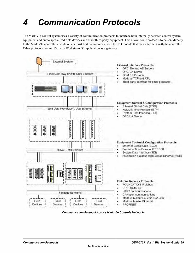
4 Communication ProtocolsThe Mark VIe control system uses a variety of communication protocols to interface both internally between control systemequipment and out to specialized field devices and other third-party equipment. This allows some protocols to be sent directlyto the Mark VIe controllers, while others must first communicate with the I/O module that then interfaces with the controller.Other protocols use an HMI with WorkstationST application as a gateway.
Communication Protocol Across Mark VIe Controls Networks
Communication Protocols GEH-6721_Vol_I_BN System Guide 99Public Information

External Interface Protocols
External interface protocols support transmitting and receiving data with third-party control, monitoring, and supervisorysystems through the Plant Data Highway (PDH). Communication is important but normally not critical to control andequipment protection. The protocol types include:
• Variable feedback and commands to and from a third-party Distributed Control System (DCS)• Alarm annunciation and management interface with third-party systems• Interface with third-party industrial protocol gateways
Equipment Control and Configuration Protocols
The Unit Data Highway (UDH) and IONet networks use several different protocols for equipment control and configuration,as described in the following table.
Equipment Control and ConfigurationProtocols Functions
Ethernet Global Data (EGD)
• Feedback and commands between HMI and Mark VIe controllers on UDH• Control data between Mark VIe controllers on UDH• Real time data between I/O modules and Mark VIe controllers on IONet• Redundant controller data synchronization
Network Time Protocol (NTP)Clock synchronization between Mark VIe controllers, I/O packs, WorkstationSTPCs, and a master time source. NTP operates on both the UDH and IONetnetworks.
System Data Interface (SDI)
• ToolboxSTconfiguration and monitoring with controllers, I/O packs, andWorkstationST PCs
• Real time alarm annunciation and management between controllers andWorkstationSTAlarm Server
• Transmission of trip log data from controllers to WorkstationSTAlarmServer
OPC-UA Server Mark VIe controller interfaces with OPC-UA client functions on UDH network
Precision Time Protocol IEEE 1588IEEE 1588 is designed for local systems requiring high precision that cannotafford the a GPS receiver at each node. The standards describe a hierarchicalmaster-slave architecture for clock distribution.
FOUNDATION Fieldbus HSEMark VIe implementation of HSE is used to couple the controller with the linkingdevice (gateway between IONet and H1).
Fieldbus Network Protocols
Fieldbus protocols network field devices (sensor and actuators) with the control system, enabling diagnostic and configurationfunctions along with traditional real time control. The Mark VIe system supports the following protocols:
• FOUNDATION Fieldbus• PROFIBUS -DP• HART communications• CANopen communications• Modbus Master RS-232, 422, 485• Modbus Master Ethernet• PROFINET
100 GEH-6721_Vol_I_BN GEH-6721_Vol_I Mark VIe and Mark VIeS Control Systems Volume IPublic Information

4.1 OPC ProtocolsThe Object Linking and Embedding for Process Control (OPC) protocols are widely-adopted standards for communicationbetween vendors across different industries. The OPC Foundation provides the specification for the standards, as well asprogramming proxy stubs. Supported OPC protocols include:
• OPC Data Access (DA) communicates real-time data• OPC Alarms and Events (AE) for alarm and event messaging and management• OPC Unified Architecture (UA) that integrates OCP-DA and OPC-AE into a common framework
Refer to the following documents for additional information:
• WorkstationST OPC DA Server Instruction Guide (GEI-100621)• WorkstationST OPC AE Server Instruction Guide (GEI-100624)• WorkstationST OPC UA Server Instruction Guide (GEI-100828)• ToolboxST User Guide for Mark Controls Platform (GEH-6703) for OPC UA configuration from the Mark VIe controller
and Mark VIe for OPC DA, AE, HDA, and UA configuration from the WorkstationST server• ControlST Software Suite How-to Guides (GEH-6808), chapters How to Interface to Third Parties Using and How to
Configure OPC AE Capability
4.1.1 WorkstationST OPC DA ServerOPC Data Access (DA) is designed for real-time data flow between industrial controllers and supervisory functions, such asHMIs and data historians. The WorkstationST-based OPC DA server includes an EGD server and SDI interface for non-EGDvariables. In Mark controls applications, the OPC DA server is commonly used to interface with the CIMPLICITYAdvancedViewer and Proficy historian.
WorkstationST OPC DA Server Example
Communication Protocols GEH-6721_Vol_I_BN System Guide 101Public Information
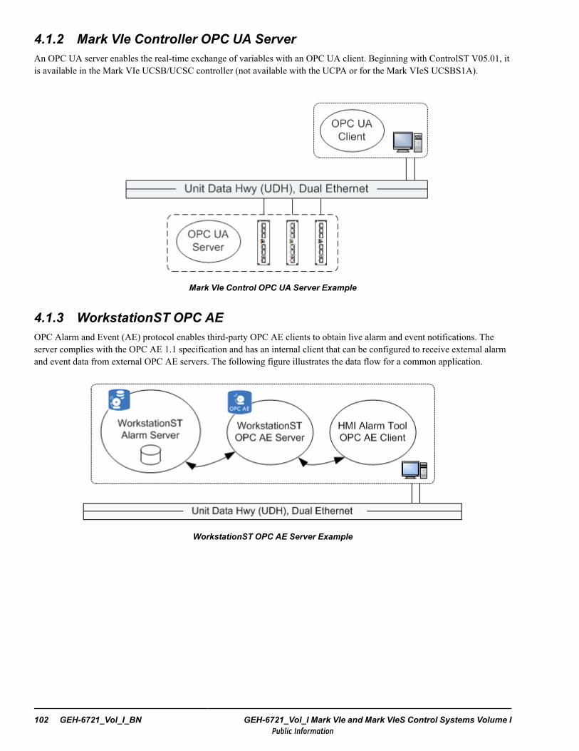
4.1.2 Mark VIe Controller OPC UA ServerAn OPC UA server enables the real-time exchange of variables with an OPC UA client. Beginning with ControlST V05.01, itis available in the Mark VIe UCSB/UCSC controller (not available with the UCPA or for the Mark VIeS UCSBS1A).
Mark VIe Control OPC UA Server Example
4.1.3 WorkstationST OPC AEOPC Alarm and Event (AE) protocol enables third-party OPC AE clients to obtain live alarm and event notifications. Theserver complies with the OPC AE 1.1 specification and has an internal client that can be configured to receive external alarmand event data from external OPC AE servers. The following figure illustrates the data flow for a common application.
WorkstationST OPC AE Server Example
102 GEH-6721_Vol_I_BN GEH-6721_Vol_I Mark VIe and Mark VIeS Control Systems Volume IPublic Information
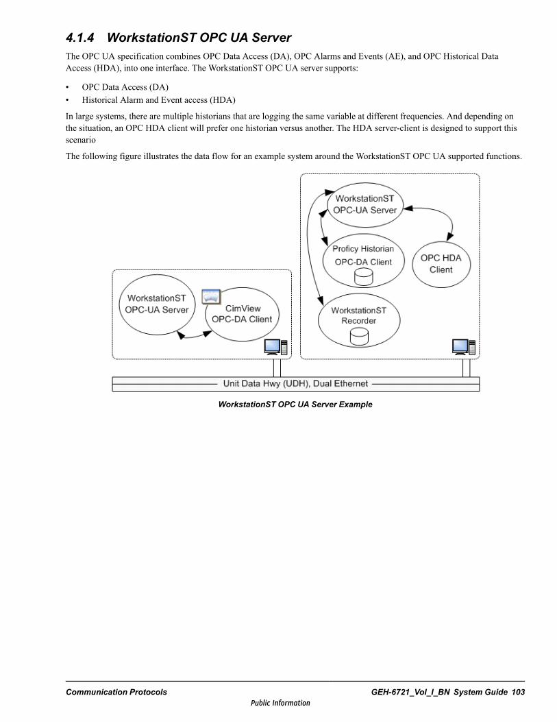
4.1.4 WorkstationST OPC UA ServerThe OPC UA specification combines OPC Data Access (DA), OPC Alarms and Events (AE), and OPC Historical DataAccess (HDA), into one interface. The WorkstationST OPC UA server supports:
• OPC Data Access (DA)• Historical Alarm and Event access (HDA)
In large systems, there are multiple historians that are logging the same variable at different frequencies. And depending onthe situation, an OPC HDA client will prefer one historian versus another. The HDA server-client is designed to support thisscenario
The following figure illustrates the data flow for an example system around the WorkstationST OPC UA supported functions.
WorkstationST OPC UA Server Example
Communication Protocols GEH-6721_Vol_I_BN System Guide 103Public Information
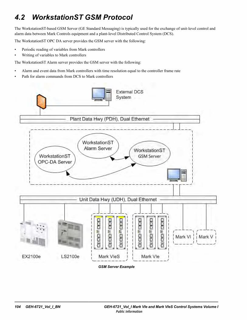
4.2 WorkstationST GSM ProtocolThe WorkstationST-based GSM Server (GE Standard Messaging) is typically used for the exchange of unit-level control andalarm data between Mark Controls equipment and a plant-level Distributed Control System (DCS).
The WorkstationST OPC DA server provides the GSM server with the following:
• Periodic reading of variables from Mark controllers• Writing of variables to Mark controllers
The WorkstationSTAlarm server provides the GSM server with the following:
• Alarm and event data from Mark controllers with time resolution equal to the controller frame rate• Path for alarm commands from DCS to Mark controllers
GSM Server Example
104 GEH-6721_Vol_I_BN GEH-6721_Vol_I Mark VIe and Mark VIeS Control Systems Volume IPublic Information

There are four types of GSM messages:
• Administrative• Event-driven data• Periodic data• Command
Administration Messages are not associated with given Mark controller. These requests are messages from the DCS to theGSM server to interrogate its capabilities.
Event Driven Messages are sent from the GSM server to the DCS in reaction to a system alarm or event occurring or clearing.Event driven messages include:
• Process alarm is initiated or clears• Internal control diagnostic alarm is initiated or clears• Process event occurs• Sequence of Event (SOE) contact input opens or closes
Periodic Data consists of variable sets transmitted from the GSM server to DCS either once or periodically (rates up to onceper second). This data is typically used to refresh DCS process display screens.
Command Requests fall into two classes:
• Process alarm command requests• Process command requests, either a momentary contact push-button or a variable write command
Note For additional information, refer to the WorkstationST GSM 3.0 User Guide (GEH-6757) and the WorkstationST GSM3.0 Application Guide (GEH-6760).
Communication Protocols GEH-6721_Vol_I_BN System Guide 105Public Information
4.3 Modbus ProtocolModbus is a Request-Response protocol typically used for Supervisory Control and Data Acquisition (SCADA) interface,either as the Master for data acquisition by the SCADA or a Slave to transmit data to the SCADA. The application data unit(ADU) layer offers three methods of implementation:
• TCP/IP• RTU• ASCII
The Request-Response protocol is straight forward to implement; however, it has an inherent latency in the Request-Responsecycle between the two computers instead of the Event Driven messages (exception reporting) available with OPC and GSM.Additionally, it does not support individual high-resolution time stamps for each alarm and event, but rather a single timestamp for a set of data transmitted from the Slave to the Master upon request.
In the Mark control systems, Modbus is supported in both the controllers and WorkstationST. For the Mark VIeS Safetycontroller, only Ethernet Modbus and the Modbus Read command from the Modbus Master is supported (Serial Modbus andthe Write command is not supported).
Note Modbus protocol does not provide security against unauthorized commands or interception of data. A separate Modbusgateway should be considered rather than a shared resource.
4.3.1 WorkstationST ModbusModbus in the WorkstationST has full support, as follows:
• One or multiple Modbus masters running simultaneously• One or multiple Modbus slaves running simultaneously• Ethernet or serial communication running simultaneously• Each Modbus page is configured with ToolboxST, enabling virtually any variable in the system to be mapped to a page
106 GEH-6721_Vol_I_BN GEH-6721_Vol_I Mark VIe and Mark VIeS Control Systems Volume IPublic Information
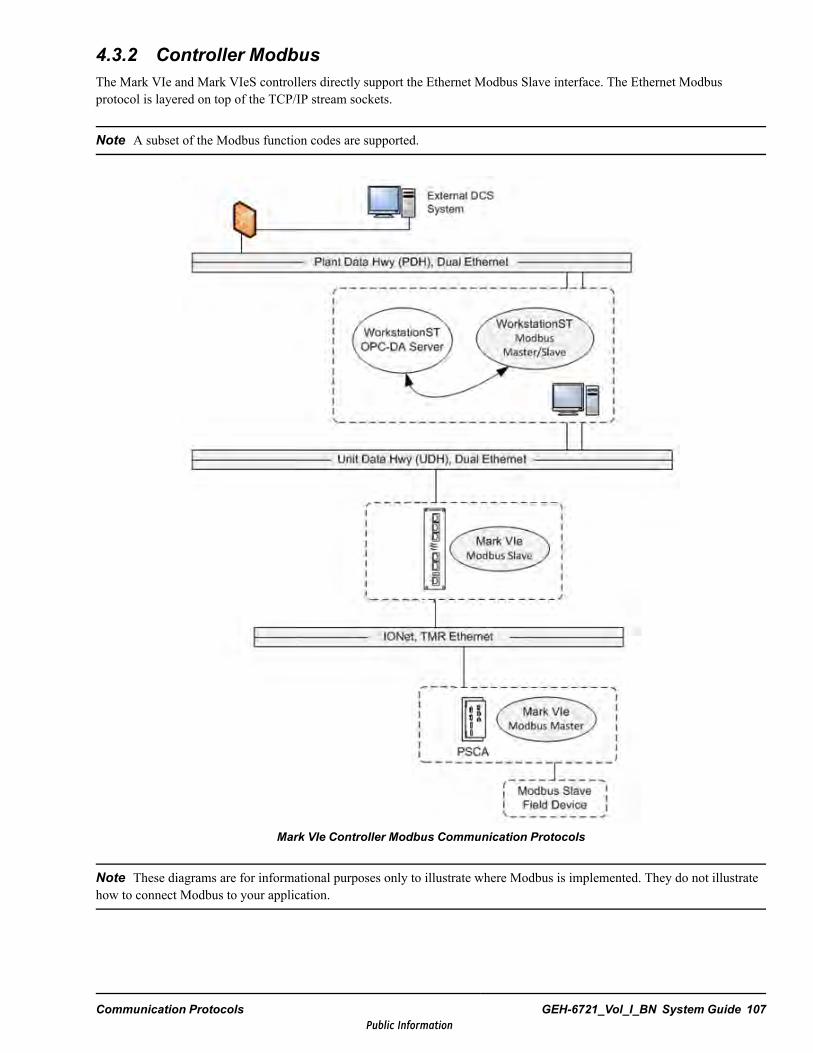
4.3.2 Controller ModbusThe Mark VIe and Mark VIeS controllers directly support the Ethernet Modbus Slave interface. The Ethernet Modbusprotocol is layered on top of the TCP/IP stream sockets.
Note A subset of the Modbus function codes are supported.
Mark VIe Controller Modbus Communication Protocols
Note These diagrams are for informational purposes only to illustrate where Modbus is implemented. They do not illustratehow to connect Modbus to your application.
Communication Protocols GEH-6721_Vol_I_BN System Guide 107Public Information

Mark VIeS Safety Controller Modbus Communication Protocols
108 GEH-6721_Vol_I_BN GEH-6721_Vol_I Mark VIe and Mark VIeS Control Systems Volume IPublic Information

4.4 Ethernet Global Data (EGD)The EGD protocol on the UDH is used for Mark VIe controller to Mark VIe HMI (running WorkstationST application), or forController to Controller communications, and is configured using the ToolboxST application for the Mark VIe controller andthe WorkstationST application. Controller data configured for transmission over EGD is separated into groups calledexchanges. Multiple exchanges make up pages. Pages can be configured either to a specific address (unicast), if supported, orto multiple consumers at the same time (broadcast or multicast), if supported.
Note IONet EGD transmissions occur between controller and I/O packs. IONet EGD communication is transparent to theuser, requiring no specific configuration by the user. An IONet EGD report can be generated in ToolboxST to providenetwork status values for all IONet communication displayed in the current component and reflects totals of the controllerexchange. For further details, refer to the ToolboxST User Guide for Mark Controls Platform (GEH-6700), the section IONetEGD Report.
Each page is identified by the combination of a Producer ID and an Exchange ID. The consumer recognizes the data andknows where to store it. EGD allows one controller component, referred to as the producer of the data, to simultaneously sendinformation at a fixed periodic rate (frame rate) to any number of peer controller components, known as the consumers. Thisnetwork supports a large number of controller components capable of both producing and consuming information.
The exchange contains a configuration signature, which displays the revision number of the exchange configuration. If theconsumer receives data with an unknown configuration signature, it makes that data unhealthy. If a transmission isinterrupted, the receiver waits three periods for the EGD message, after which it times out and the data is consideredunhealthy.
EGD Communications FeaturesFeature DescriptionExample types ofcommunication
Supervisory data is transmitted periodically at either 480 or 960 ms.Controller data is transmitted to the HMI at frame rate.Controller to Controller data is transmitted at 40 ms.
Message Type Broadcast – a message sent to all stations on a subnetUnicast – a directed message to one stationMulticast – a message sent to a group of destinations simultaneously in a single transmission
Redundancy Refer to the section Controller Redundancy to Prevent Loss of Communication.Sizes Each exchange can contain a maximum of 1400 bytes of data (or payload). Pages can contain
multiple exchanges. The number of exchanges within a page and the number of pages within anEGD node are limited by each EGD device type. The Mark VIe controller does not limit thenumber of, exchanges, or pages.
Message Integrity Ethernet supports a 32-bit CRC appended to each Ethernet packet.Reception timeout is determined by EGD device type. The exchange times out after anexchange update had not occurred within four times the exchange period, using Sequence ID.Missing/out of order packet detectionUDP and IP header checksumsConfiguration signature (data layout revision control)Exchange size validation
Function Codes EGD allows each controller to send a block of information to, or receive a block from, othercontrollers in the system.
Communication Protocols GEH-6721_Vol_I_BN System Guide 109Public Information
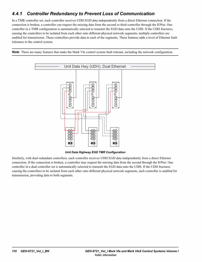
4.4.1 Controller Redundancy to Prevent Loss of CommunicationIn a TMR controller set, each controller receives UDH EGD data independently from a direct Ethernet connection. If theconnection is broken, a controller can request the missing data from the second or third controller through the IONet. Onecontroller in a TMR configuration is automatically selected to transmit the EGD data onto the UDH. If the UDH fractures,causing the controllers to be isolated from each other onto different physical network segments, multiple controllers areenabled for transmission. These controllers provide data to each of the segments. These features adds a level of Ethernet faulttolerance to the control system.
Note There are many features that make the Mark VIe control system fault tolerant, including the network configuration.
Unit Data Highway EGD TMR Configuration
Similarly, with dual redundant controllers, each controller receives UDH EGD data independently from a direct Ethernetconnection. If the connection is broken, a controller may request the missing data from the second through the IONet. Onecontroller in a dual controller set is automatically selected to transmit the EGD data onto the UDH. If the UDH fracturescausing the controllers to be isolated from each other onto different physical network segments, each controller is enabled fortransmission, providing data to both segments.
110 GEH-6721_Vol_I_BN GEH-6721_Vol_I Mark VIe and Mark VIeS Control Systems Volume IPublic Information

4.5 System Data Interface (SDI) ProtocolThe SDI protocol is a configuration protocol layered upon TCP/IP. SDI is used primarily between the ToolboxST applicationand the other control system devices on the UDH (controllers, HMIs, and Historians). SDI commands support configurationdownloads, file transfers, debugging, live data access, and a variety of other activities. The SDI connection between theToolboxST application and the controllers is secured when the SecurityST server is deployed. SDI is also used by theWorkstationST application to monitor controller status, upload trip logs, transport alarms from the devices to theWorkstationSTAlarm Server, and to transmit alarm commands to the controllers.
Note The Mark VIe control systems can support up to a maximum of 10 supervisory PCs with individual alarm serverconnections to a unit controller (not including OSM and Historian).
The total number of SDI connections to any particular controller must be limited to prevent overburdening controllerresources, so attention must be paid to the overall system architecture during the application engineering design phase. Forexample, supporting a large number of WorkstationSTAlarm Viewers is best accomplished by deploying a centralized alarmserver with a single SDI connection to the controller rather than having each HMI run its own alarm server and therefore aseparate SDI connection from the controller to each HMI. In addition, sites with multiple HMIs should limit requests forcontroller trip logs to be made from only a few HMIs as to not overburden the Mark VIe controller.
Because EGD does not create a connection per HMI, EGD is typically used for live data transfer and to fan data out fromcontrollers to a large number of HMIs. SDI is used for live data in cases such as ExperTune® support, where a large numberof variables must be made available but only a few variables will be accessed at any one time.
An SDI server runs on the Mark VIe controller to provides a communication mechanism between the controller and the HMI.The server on the controller waits for the ToolboxST and WorkstationST applications to establish connections. It allows theHMI to retrieve data from the controller and for the ToolboxST and WorkstationST applications to run commands in thecontroller.
SDI is a communication scheme that is built on top of TCP/IP, which provides a reliable delivery mechanism between twocommunicating parties. Data that is sent from one to the other is guaranteed to be delivered, and delivered in the correct order.When a segment of data is sent by TCP/IP, the sender will wait for an acknowledgement of the segment. If theacknowledgment is not received, the data will be resent. Also, if data is not delivered in the correct order, TCP/IP willreorganize it in the correct order. TCP/IP will also discard any duplicate packets.
Communication Protocols GEH-6721_Vol_I_BN System Guide 111Public Information
4.6 Network Time Protocol (NTP)
4.6.1 Control System Time SynchronizationThe control time synchronization option synchronizes all controllers and HMIs on the UDH to a Global Time Source (GTS)or master time source. Typical GTS systems are Global Positioning Satellite (GPS) receivers such as the StarTime GPS Clockor similar time processing hardware.
Note Refer to GEH-6808, the section How to Configure Time Synchronization in the ToolboxSTApplication.
GE recommends using a dedicated NTP box that is not part of the HMI, but a time/frequency processor board can be placedin the HMI as an alternative. This NTP box or board acquires time from the master time source with a high degree ofaccuracy. When the HMI receives the time signal, it makes the time information available to the turbine and generatorcontrols on the network by way of NTP. The HMI server provides time to client devices either by broadcasting time, or byresponding to NTP time queries, or both methods.
Supplying a time/frequency processor board in another HMI server as a backup can provide redundant time synchronization.Normally, the primary HMI server on the UDH is the time master for the UDH, and other computers without thetime/frequency board are time slaves. The time slave computes the difference between the returned time and the recordedtime of request and adjusts its internal time. Each time slave can be configured to respond to a time master through unicastmode or broadcast mode.
Local time is used for display of real time data by adding a local time correction to UTC. A node’s internal time clock isnormally UTC rather than local. This is done because UTC time steadily increases at a constant rate while corrections areallowed to local time. Historical data is stored with global time to minimize discontinuities.
4.6.2 Clock Stratum
Note This stratum is different from the clock strata used in telecommunication systems.
The term Stratum defines the levels in the hierarchy of clocks that makeup NTP. Each level is assigned a layer numberstarting with zero at the top. The stratum level defines its distance from the reference clock and prevents cyclicaldependencies in the hierarchy.
Note Stratum is not an indication of the quality or reliability, it is common to fine Stratum 3 time sources that are higherquality than other Stratum 2 time sources.
Stratum 0 are devices such as atomic (cesium, rubidium) clocks, GPS clocks, or other radio clocks. Stratum 0 devices areusually not attached to the network. Instead, they are locally connected to computers (for example, through an RS-232connection using a pulse per second signal).
Stratum 1 are computers attached to Stratum 0 devices. Normally they act as servers for timing requests from Stratum 2servers through NTP. These computers are also referred to as time servers.
Stratum 2 are computers that send NTP requests to Stratum 1 servers. Normally a Stratum 2 computer will reference anumber of Stratum 1 servers and use the NTP algorithm to gather the best data sample, dropping any Stratum 1 servers thatare wrong. Stratum 2 computers are grouped with other Stratum 2 computers to provide more stable and robust time for alldevices in the peer group. Stratum 2 computers normally operate as servers for Stratum 3 NTP requests.
Stratum 3 are computers that use exactly the same NTP functions of peering and data sampling as Stratum 2, and can beused as servers for lower strata. NTP support up to 256 strata, depending on the version of NTP protocol in use.
112 GEH-6721_Vol_I_BN GEH-6721_Vol_I Mark VIe and Mark VIeS Control Systems Volume IPublic Information
4.6.3 NTP TimestampsThe 64-bit timestamps used by NTP consist of a 32-bit seconds part and a 32-bit fractional second part, giving NTP a timescale of 232 seconds (136 years) and a theoretical resolution of 2-32 seconds (233 picoseconds). The timescale wraps aroundevery 232 seconds (136 years). NTP uses an epoch of January 1, 1900. The first rollover will occur in 2036.
Note The current NTPv4 format supports Era Number and Era Offset, which corrects date rollover issues.
Implementations should disambiguate NTP time using a knowledge of the approximate time from other sources. Since NTPonly works with the differences between timestamps and never their absolute values, the wraparound is invisible as long asthe timestamps are within 68 years of each other. This means that the rollover will be invisible for most running systems,since they will have the correct time to within a very small tolerance. However, systems that are starting up need to know thedate within no more than 68 years. The Mark VIe control uses a battery powered hardware clock to avoid this problem.
4.6.4 Clock Synchronization AlgorithmTo synchronize its clock with a remote server, the NTP client must compute the round-trip delay time. The round-trip delay =(t3 - t0) - (t2- t1).
The time of the request packet transmission is t0, the time of the packet reception is t1, the time of the response packettransmission is t2, and the time of the response packet reception is t3. The elapsed time on the client side between the emissionof the request packet and the reception of the response packet is t3 - t0. The time the server waited before sending the answeris t2 - t1.
The offset = ((t1 - t0) + (t2- t3)) / 2.
The NTP synchronization is correct when both the incoming and outgoing routes between the client and the server have asymmetrical nominal delay. If the routes do not have a common nominal delay, the synchronization has a systematic bias ofhalf the difference between the forward and backward travel time.
4.6.5 Clients and ServersThe relationship between NTP servers and clients can be configured to operate in several ways. Computers using NTP canoperate in different modes with respect to different machines. For example, a single machine could be a client of a machinewith a lower stratum number, while being a peer to a machine on the same stratum, and a broadcast server to a number ofclients at higher stratum numbers.
Servers provide time to clients. Clients send requests to the server and the server sends back a time stamped response,along with information such as accuracy and stratum.
Clients get time responses from a NTP server or servers, and uses the information to calibrate its clock. This consists of theclient determining how far its clock is off and adjusting its time to match that of the server. The maximum error is determinedbased on the round-trip delay time for the packet to be received.
Peers are members of a group of NTP servers that are tightly coupled. In a group of two peers, at any given time, the mostaccurate peer is acting as a server and the other peers are acting as clients. The result is that peer groups will have closelysynchronized times without requiring a single server to be specified.
Communication Protocols GEH-6721_Vol_I_BN System Guide 113Public Information

Broadcast or Multicast Mode
The NTP server can operate in either broadcast or multicast mode. Broadcast servers send periodic time updates to abroadcast address, while multicast servers send periodic updates to a multicast address. Using broadcast packets can greatlyreduce the NTP traffic on a network, especially for a network with many NTP clients.
The NTP broadcast or multicast client listens for NTP packets on a broadcast or multicast address. When the first packet isreceived, it attempts to quantify the delay to the server to better quantify the correct time from later broadcasts. This isaccomplished by a series of brief interchanges where the client and server function as a regular (non-broadcast) NTP clientand server. Once these interchanges occur, the client has an idea of the network delay and can estimate the time based only onbroadcast packets. If this interchange is not desirable, it can be disabled using NTP’s access control features.
4.6.6 Accuracy and ResolutionNTP may take several minutes or even hours to adjust a system's time to the ultimate degree of accuracy. There are severalreasons for this. NTP averages the results of several time exchanges to reduce the effects of variable latency, so it may takeseveral minutes for NTP to even reach consensus on what the average latency is. Generally this happens in about fiveminutes. In addition, it often takes several adjustments for NTP to reach synchronization. Users should not expect NTP toimmediately synchronize two clocks.
To allow clocks to quickly achieve high accuracy, yet avoid overshooting the time with large time adjustments, NTP uses asystem where large adjustments occur quickly and small adjustments occur over time. For small time differences (less than128 ms), NTP uses a gradual adjustment. This is called slewing. For larger time differences, the adjustment is immediate. Thisis called stepping. If the accuracy of the clock becomes too insufficient (off by more than 17 minutes), NTP aborts the NTPdaemon, with the assumption that something is wrong with either the server or client. To accurately synchronize with a server,the client needs to avoid step adjustments.
The degree of synchronization to a server is dependent primarily on network latency. Because NTP uses UDP packets, trafficcongestion could temporarily prevent synchronization, but the client can still self-adjust, based on its historic drift. Undergood conditions on a LAN without too many routers or other sources of network delay, synchronization to within a fewmilliseconds is normal. Anything that adds latency, such as hubs, switches, routers, or network traffic, will reduce thisaccuracy.
If even more synchronization accuracy is required, use the following options:
• Connecting directly to a reference clock. Then, accuracy is limited only by the accuracy of the reference clock and thehardware and software latencies involved in these connections.
• Clocks can use pulse per second (PPS) radio receivers, which receive on-the-second radio pulses from a nationalstandards organization. If the time is within a fraction of a second, the PPS pulses can be used to precisely synchronize tothe tick of the second. The method achieves accuracies in the tens of microsecond range.
114 GEH-6721_Vol_I_BN GEH-6721_Vol_I Mark VIe and Mark VIeS Control Systems Volume IPublic Information
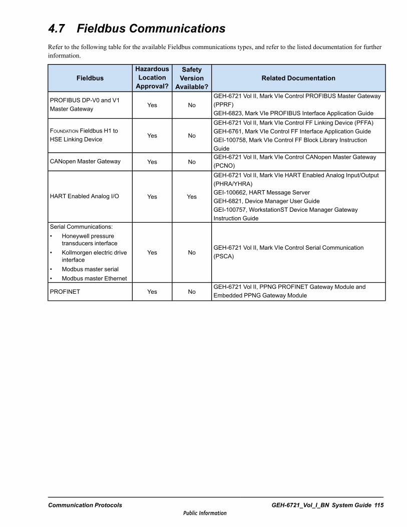
4.7 Fieldbus CommunicationsRefer to the following table for the available Fieldbus communications types, and refer to the listed documentation for furtherinformation.
FieldbusHazardousLocationApproval?
SafetyVersion
Available?Related Documentation
PROFIBUS DP-V0 and V1Master Gateway Yes No
GEH-6721 Vol II, Mark VIe Control PROFIBUS Master Gateway(PPRF)GEH-6823, Mark VIe PROFIBUS Interface Application Guide
FOUNDATION Fieldbus H1 toHSE Linking Device Yes No
GEH-6721 Vol II, Mark VIe Control FF Linking Device (PFFA)GEH-6761, Mark VIe Control FF Interface Application GuideGEI-100758, Mark VIe Control FF Block Library InstructionGuide
CANopen Master Gateway Yes NoGEH-6721 Vol II, Mark VIe Control CANopen Master Gateway(PCNO)
HART Enabled Analog I/O Yes Yes
GEH-6721 Vol II, Mark VIe HART Enabled Analog Input/Output(PHRA/YHRA)GEI-100662, HART Message ServerGEH-6821, Device Manager User GuideGEI-100757, WorkstationST Device Manager GatewayInstruction Guide
Serial Communications:• Honeywell pressure
transducers interface• Kollmorgen electric drive
interface• Modbus master serial• Modbus master Ethernet
Yes NoGEH-6721 Vol II, Mark VIe Control Serial Communication(PSCA)
PROFINET Yes NoGEH-6721 Vol II, PPNG PROFINET Gateway Module andEmbedded PPNG Gateway Module
Communication Protocols GEH-6721_Vol_I_BN System Guide 115Public Information

Notes
116 GEH-6721_Vol_I_BN GEH-6721_Vol_I Mark VIe and Mark VIeS Control Systems Volume IPublic Information

5 Technical Regulations, Standards,and EnvironmentThis chapter describes the technical regulations, standards, and environmental guidelines used for the design of all printedcircuit boards, modules, core components, panels, and cabinet line-ups in the control system.
5.1 Safety StandardsEN61010-1:2010 (3rd Edition) Safety Requirements for Electrical Equipment for Measurement, Control, and
Laboratory Use, Part 1: General RequirementsCAN/CSA® 22.2 No. 61010-1-12 Safety Requirements for Electrical Equipment for Measurement, Control, and
Laboratory Use, Part 1: General RequirementsUL 61010-1 (3rd Edition) Safety Standard for Electrical and Electronic Test, Measuring, Controlling, and
Related Equipment – General RequirementsIEC® 60529 Intrusion Protection Codes IP20 minimum (NEMA 1)
Technical Regulations, Standards, and Environment GEH-6721_Vol_I_BN System Guide 117Public Information

5.2 Conditions for ComplianceIf the following conditions for compliance are not met or if unapproved third-party equipment is included in the Mark VIecontrol cabinet, then the user is responsible for obtaining the appropriate Low Voltage Safety and EMC certifications for theassembled Mark VIe control & IO based cabinets.
• Mark VIe control equipment must be mounted inside a grounded steel enclosure, with doors that require a tool or key toopen, and 0.86 mm minimum steel thickness. The enclosure must provide a minimum Intrusion Protection of IP 20 andan internal micro-environment of not more than Pollution Degree 2.
• PE and FE connections must be clearly marked. Customer must connect PE/FE to suitable building ground systemthrough minimum 120 mm2 (4/0 AWG) gauge wire. Refer to the chapter Installation Guidelines, the section Groundingfor more information.
• Use only Mark VIe family of controllers, IO, switches, and power supplies.• Customer power supply mains connection terminal boards must be clearly marked with L (Line) and N (Neutral) for each
AC supply feed connection and Hi (+) and Lo (-) for each DC supply feed connection.• A Power Requirements nameplate with supply source designations, voltage, and rated current shall be located on the
front door of the cabinet with the customer supply mains connections. Refer to the chapter Installation Guidelines, thesection Power Requirements for details and nameplate examples.
• The customer shall provide an easily accessible external disconnect device for each of the mains supplies near the controlcabinet. The customer shall provide external 30 A two-pole circuit breaker protection for each 120 Vac and 125 V dcmains and 15 A two-pole circuit breaker protection for each 240 Vac and 220 V dc mains. Circuit breaker can serve asthe Disconnect Device if mounted accessible to the control cabinet.
• Any accessory outlet / socket must be labeled near the outlet with the max rated current.• All AC and DC power supply mains must connect thru a Mark VIe Overvoltage Transient Protection and EMI Filter
circuit. These OVand EMI filter circuits are built-in to the JPDB and JPDF Power Distribution Modules. If JPDB/JPDFare not used to distribute AC and DC power supply mains to the Mark VIe control, then a separate GE Filter Module246B8279Gx should be used to filter the mains. Refer to GEH-6721 Volume II, the chapter PDM Power DistributionModules for more information.
• Elevation shall not exceed 2000 m for compliance to 61010-1.• Appropriate Warning nameplates shall be applied to the front door of each cabinet and shall include appropriate warning
symbols per IEC 61010-1 per Table 1. See examples below. Warning nameplates shall highlight the presence of electricalcircuits that must be disconnected before opening the enclosure for servicing, electrical shock or burn hazard, QualifiedPersonnel Only, and include symbols 12 and 14 from IEC 61010-1 Table 1.
118 GEH-6721_Vol_I_BN GEH-6721_Vol_I Mark VIe and Mark VIeS Control Systems Volume IPublic Information
5.3 Electrical
5.3.1 Electromagnetic Compatibility Directive (EMC) 2014/30/EU
Attention
Equipment is not approved for use in a residential, commercial or light industrialenvironment and should not be connected to a residential electric power network. ForEMC Directive compliance, Mark VIe components shipped loose from the factorymust be installed in an enclosure with a minimum steel thickness of 0.86 mm and havea minimum Intrusion Protection (IP) of 20.
The Mark VIe control fulfils the requirements listed in the following table.
Code DescriptionEN 55011:2009 + A1:2010 ISM equipment - Electromagnetic disturbance characteristicsEN 61000-6-2: 2005 Generic Immunity Industrial EnvironmentEN/IEC 61326-1 Electrical equipment for measurement, control and laboratory use – EMC requirementsIEC 61000-4-2 Electrostatic Discharge SusceptibilityIEC 61000-4-3 Radiated RF Immunity
IEC 61000-4-4 Electrical Fast Transient Susceptibility
IEC 61000-4-5 Surge Immunity
IEC 61000-4-6 Conducted RF ImmunityIEC 61000-4-11 Voltage Variation, Dips and Interruptions
5.3.2 Low Voltage Directive 2014/35/EUUnder the conditions specified in this document, the Mark VIe control fulfils the requirements of CAN/CSA-C22.2 No.61010-1-12, UL Std. No. 61010-1 (3rd Edition), and EN 61010-1 (3rd edition) Safety Requirements for Electrical Equipmentfor Measurement, Control, and Laboratory Use, Part 1: General Requirements.
Warning
The protection provided by this equipment may be impaired if it is used in a mannerthat is not specified by the manufacturer.
Technical Regulations, Standards, and Environment GEH-6721_Vol_I_BN System Guide 119Public Information
5.3.3 Supply Voltage
5.3.3.1 Line VariationsMark VIe control equipment meets the requirements for Overvoltage Category II equipment (IEC 60664-1:2007) under theConditions for Compliance specified in this document.
Ac Supplies – Operating line variations of ±10%IEEE STD 141-1993 defines the Equipment Terminal Voltage – Utilization voltage.
The above meets IEC 60204-1 2005, and exceeds IEEE STD 141-1993, and ANSI C84.1-1989.
Dc Supplies – Operating line variations of -30%, 10% or 140 V dc. This meets IEC 60204-1 2005.
5.3.3.2 Voltage UnbalanceLess than 2% of positive sequence component for negative sequence componentLess than 2% of positive sequence component for zero sequence components
This meets IEC 60204-1 2005 and IEEE STD 141-1993.
5.3.3.3 Harmonic Distortion Voltage UnbalanceVoltage: Less than 10% of total rms voltages between live conductors for 2nd through 5th harmonic
Additional 2% of total rms voltages between live conductors for sum of 6th through 30th harmonic
This meets IEC 60204-1 2005.
Current: The system specification is not per individual equipment
Less than 15% of maximum demand load current for harmonics less than 11Less than 7% of maximum demand load current for harmonics between 11 and 17Less than 6% of maximum demand load current for harmonics between 17 and 23Less than 2.5% of maximum demand load current for harmonics between 23 and 35
The above meets IEEE STD 519 1992.
5.3.3.4 Frequency VariationsFrequency variation of ±5% when operating from ac supplies (20 Hz/sec slew rate)
This exceeds IEC 60204-1 2005.
5.3.3.5 SurgeWithstand 2 kV common mode, 1 kV differential mode
This meets IEC 61000-4-5 (ENV50142), and ANSI C62.41 (combination wave).
120 GEH-6721_Vol_I_BN GEH-6721_Vol_I Mark VIe and Mark VIeS Control Systems Volume IPublic Information
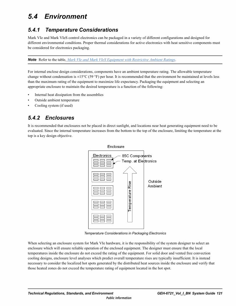
5.4 Environment
5.4.1 Temperature ConsiderationsMark VIe and Mark VIeS control electronics can be packaged in a variety of different configurations and designed fordifferent environmental conditions. Proper thermal considerations for active electronics with heat sensitive components mustbe considered for electronics packaging.
Note Refer to the table, Mark VIe and Mark VIeS Equipment with Restrictive Ambient Ratings.
For internal enclose design considerations, components have an ambient temperature rating. The allowable temperaturechange without condensation is ±15°C (59 °F) per hour. It is recommended that the environment be maintained at levels lessthan the maximum rating of the equipment to maximize life expectancy. Packaging the equipment and selecting anappropriate enclosure to maintain the desired temperature is a function of the following:
• Internal heat dissipation from the assemblies• Outside ambient temperature• Cooling system (if used)
5.4.2 EnclosuresIt is recommended that enclosures not be placed in direct sunlight, and locations near heat generating equipment need to beevaluated. Since the internal temperature increases from the bottom to the top of the enclosure, limiting the temperature at thetop is a key design objective.
Temperature Considerations in Packaging Electronics
When selecting an enclosure system for Mark VIe hardware, it is the responsibility of the system designer to select anenclosure which will ensure reliable operation of the enclosed equipment. The designer must ensure that the localtemperatures inside the enclosure do not exceed the rating of the equipment. For solid door and vented free convectioncooling designs, enclosure level analyses which predict overall temperature rises are typically insufficient. It is insteadnecessary to consider the localized hot spots generated by the distributed heat sources inside the enclosure and verify thatthose heated zones do not exceed the temperature rating of equipment located in the hot spot.
Technical Regulations, Standards, and Environment GEH-6721_Vol_I_BN System Guide 121Public Information
For all types of enclosure systems, it is important to highlight the potential effect of changes from the original design. GEdesigned enclosure systems are engineered to maintain the Mark VIe system components within their specified temperatureratings. Modifying the enclosure or adding additional equipment to the enclosure could potentially compromise the thermaldesign.
While effective enclosure cooling can be accomplished in many ways, including active cooling like air conditioners,thermoelectric coolers, or vortex coolers, most enclosures are air cooled using one of the following cooling systems. Thefollowing are key points to consider when selecting one of these systems and are not intended to take the place of properenclosure thermal analyses.
5.4.2.1 Solid DoorSolid door enclosures are an occasional necessity where environmental conditions outside the enclosure are potentiallyharmful to the enclosed equipment. Great care should be used in applying fully enclosed cabinets without supplementalcooling, however, as relatively low power can result in significant internal temperature rises. For this reason, and because theenclosure can also be susceptible to temperature rise due to unanticipated heat sources outside the enclosure, this type ofarchitecture is only recommended where additional analysis validates that thermal design requirements are met.
5.4.2.2 Free Convection CooledFree convection cooled ventilated enclosures are commonly used for control equipment and are suitable in many cases forproviding sufficient cooling air to internal equipment. The application of filters to the air vents is also a common practice andcan provide similar Ingress Protection (IP) rating to a solid door. It should be noted, however, that a filtered cabinet withclogged filters will function like a solid door enclosure and can result in over-temperature conditions. For this reason, it isrecommended that the use of filters be limited to cases where the additional IP rating is required. In those cases, the filtersmust be regularly maintained to ensure proper operation of the cooling system.
5.4.2.3 Fan CooledFan cooled ventilated enclosures are typically used on enclosures where greater thermal margin is desired or where theambient temperature outside the enclosure is close to the operating temperature of the internal equipment. The fan cooledenclosures can also be provided with filters to improve the IP rating of the enclosure. Again the filters should be regularlymaintained to ensure that the cooled system operates to its required capability. While fan cooled systems can ideally maintaininternal enclosure temperatures within a few degrees of the external temperature, care must still be used when applying thesesystems to ensure that all components receive adequate cooling air. It is possible in forced cooling systems to havecomponents which experience greater temperature rises than they would in free convection if the component is located in anarea of poor circulation or recirculation.
122 GEH-6721_Vol_I_BN GEH-6721_Vol_I Mark VIe and Mark VIeS Control Systems Volume IPublic Information
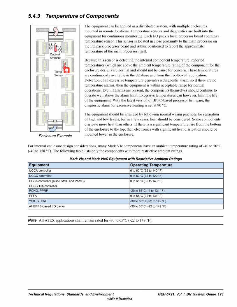
5.4.3 Temperature of Components
Cabinet Ambient
Temp. Sensor
Enclosure Example
The equipment can be applied as a distributed system, with multiple enclosuresmounted in remote locations. Temperature sensors and diagnostics are built into theequipment for continuous monitoring. Each I/O pack’s local processor board contains atemperature sensor. This sensor is located in close proximity to the main processor onthe I/O pack processor board and is thus positioned to report the approximatetemperature of the main processor itself.
Because this sensor is detecting the internal component temperature, reportedtemperatures (which are above the ambient temperature rating of the component for theenclosure design) are normal and should not be cause for concern. These temperaturesare continuously available in the database and from the ToolboxST application.Detection of an excessive temperature generates a diagnostic alarm, so if there are notemperature alarms, then the equipment is within acceptable range for normaloperations. Even if alarms are present, the components themselves should continue tooperate well above the alarm limit. Excessive temperatures can however, limit the lifeof the equipment. With the latest version of BPPC-based processor firmware, thediagnostic alarm for excessive heating is set at 90 °C.
The equipment should be arranged by following normal wiring practices for separationof high and low levels, but in a few cases, heat should be considered. Some componentsdissipate more heat than others. If there is a significant temperature rise from the bottomof the enclosure to the top, then electronics with significant heat dissipation should bemounted lower in the enclosure.
For internal enclosure design considerations, many Mark VIe components have an ambient temperature rating of -40 to 70°C(-40 to 158 °F). The following table lists only the components with more restrictive ambient ratings.
Mark VIe and Mark VIeS Equipment with Restrictive Ambient Ratings
Equipment Operating TemperatureUCCA controller 0 to 60°C (32 to 140 °F)UCCC controller 0 to 50°C (32 to 122 °F)UCSA controller (also PMVE and PAMC)UCSBH3A controller
0 to 65°C (32 to 149 °F)
PCNO, PPRF -20 to 55°C (-4 to 131 °F)PFFA 0 to 55°C (32 to 131 °F)YSIL, YDOA -30 to 65°C (-22 to 149 °F)All BPPB-based I/O packs -30 to 65°C (-22 to 149 °F)
Note All ATEX applications shall remain rated for -30 to 65°C (-22 to 149 °F).
Technical Regulations, Standards, and Environment GEH-6721_Vol_I_BN System Guide 123Public Information
5.4.4 Shipping and Storage TemperatureTemperature range during equipment shipping and storage is listed in the following table.
Equipment Temperature RangeMark VIe I/O pack, modules, and controllers –40 to 85°C (-40 to 185 °F)
Control Server –40 to 65°C (-40 to 149 °F)
Cisco network switches–40 to 85°C (-40 to 185 °F)Refer to www.Cisco.com for more detailed product information.
5.4.5 Control Room Operating EnvironmentTo ensure proper performance and normal operational life, the control room environment should be maintained as follows:
Note Higher ambient temperature decreases the life expectancy of any electronic component. Keeping ambient air in thepreferred (cooler) range should extend component life.
Ambient temperature (preferred): 20 to 30°C (68 to 86 °F)
Relative humidity: 5 to 95%, non-condensing
Environments that include excessive amounts of any of the following elements reduce cabinet performance and life:
• Dust, dirt, or foreign matter• Vibration or shock• Moisture or vapors• Rapid temperature changes• Acid or caustic fumes• Power line fluctuations• EMI or noise introduced by:
− Radio frequency signals, typically from nearby portable transmitters− Stray high voltage or high-frequency signals, typically produced by arc welders, unsuppressed relays, contactors, or
brake coils operating near control circuits
Note Enclosures can be custom engineered for other locations if desired.
The preferred location for the control system cabinet would be in an environmentally controlled room or in the control roomitself. The cabinet should be mounted where the floor surface allows for attachment in one plane (a flat, level, and continuoussurface). The customer provides the mounting hardware. Lifting lugs are provided and if used, the lifting cables must notexceed 45° from the vertical plane. Finally, the cabinet is equipped with a door handle, which can be locked for security.
Interconnecting cables can be brought into the cabinet through removable access plates. Convection cooling of the cabinetrequires that conduits be sealed to the access plates. In addition, air passing through the conduit must be within the acceptabletemperature range as listed previously.
5.4.6 HumidityThe ambient humidity range is 5 to 95% non-condensing.
124 GEH-6721_Vol_I_BN GEH-6721_Vol_I Mark VIe and Mark VIeS Control Systems Volume IPublic Information
5.4.7 Elevation
Note † Elevation shall not exceed 2000 m for compliance to 61010-1.
Equipment elevation is related to the equivalent ambient air pressure:
• Normal operation: 0 to 1000 m (0 to 3280.8 ft) at 101.3 to 89.8 kPa• Extended operation: 1000 to 3000 m† (3280.8 to 6561.7 ft) at 89.8 to 69.7 kPa
The extended operation and shipping specifications exceed EN50178.• Shipping: 4600 m (15091.8 ft) at 57.2 kPa max
Note For extended altitude operation, the maximum ambient temperature rating of the equipment should be reduced by 1°C(3.4 °F) for each additional 410 m (1345 ft) above 1000 m (3280.83 ft). Therefore, an I/O pack rated for 65°C (149 °F) at1000 m (3280.8 ft) will be rated for 62.6°C (144.7 °F) at 2000 m (6562 ft).
5.4.8 ContaminantsThe control equipment withstands the following concentrations of corrosive gases at 50% relative humidity and 40°C (104 °F):
Note This meets EN50178 Section A.6.1.4 Table A.2 (m).
Corrosive Gas ConcentrationSulfur dioxide (SO2) 30 ppbHydrogen sulfide (H2S) 10 ppbNitrous fumes (NO) 30 ppbChlorine (Cl2) 10 ppbHydrogen fluoride (HF) 10 ppbAmmonia (NH3) 500 ppbOzone (O3) 5 ppb
5.4.9 Vibration
5.4.9.1 SeismicUniversal Building Code (UBC) - Seismic Code section 2312 Zone 4 (Optional)
5.4.9.2 Operating/Installed at SiteVibration of 1.0 G Horizontal, 0.5 G Vertical at 15 to 120 Hz
Refer to Seismic UBC for frequencies lower than 15 Hz.
Technical Regulations, Standards, and Environment GEH-6721_Vol_I_BN System Guide 125Public Information

5.4.10 Applications in Hazardous Locations (HazLoc)Certain controllers, I/O packs, terminal boards, option boards, trip boards, power distribution boards, and IONet switches aredesigned to operate in hazardous locations (Class 1, Division 2, Groups A, B, C, and D; Class I, Zone 2; and ATEX II 3 G).Refer to Mark VIe and Mark VIeS Control Systems Equipment in Hazardous Locations (HazLoc) Instruction Guide(GEH-6725) and Mark VIeS Functional Safety System Equipment in Hazardous Locations (HazLoc) Instruction Guide(GEH-6861) for more information.
Note ATEX applications are rated only for operation within an enclosure with ambient temperatures from -30 to 65 °C (-22to 158 °F). With the latest version of firmware, the excessive heat diagnostic alarm for BPPC-based I/O packs is set at 90°C(194 °F).
5.4.11 Applications in Harsh EnvironmentsThe Mark VIe control product line is suitable for use in G3 harsh environments, as defined in ANSI/ISA-71.04-2013Environmental Conditions for Process Measurement and Control Systems: Airborne Contaminants.
Note For Mark VIe control products, G3 compatibility does not depend on conformal coating, however conformal coatingis available for certain Mark VIe products.
126 GEH-6721_Vol_I_BN GEH-6721_Vol_I Mark VIe and Mark VIeS Control Systems Volume IPublic Information
6 Installation GuidelinesThis chapter defines installation requirements for the control system. Specific topics include GE installation support, wiringpractices, grounding, typical equipment weights and dimensions, and power dissipation and heat loss.
Warning
This equipment contains a potential hazard of electric shock or burn. Only personnelwho are adequately trained and thoroughly familiar with the equipment and theinstructions should install, operate, or maintain this equipment.
6.1 Installation SupportGE’s system warranty provisions require both quality installation and that a qualified service engineer be present at the initialequipment startup. To assist the customer, GE offers both standard and optional installation support. Standard support consistsof documents that define and detail installation requirements. Optional support is typically the advisory services that thecustomer may purchase.
6.1.1 Early PlanningTo help ensure a fast and accurate exchange of data, a planning meeting with the customer is recommended early in theproject. This meeting should include the customer’s project management and construction engineering representatives. Itshould accomplish the following:
• Familiarize the customer and construction engineers with the equipment• Set up a direct communication path between GE and the party making the customer’s installation drawings• Determine a drawing distribution schedule that meets construction and installation needs• Establish working procedures and lines of communication for drawing distribution
Installation Guidelines GEH-6721_Vol_I_BN System Guide 127Public Information
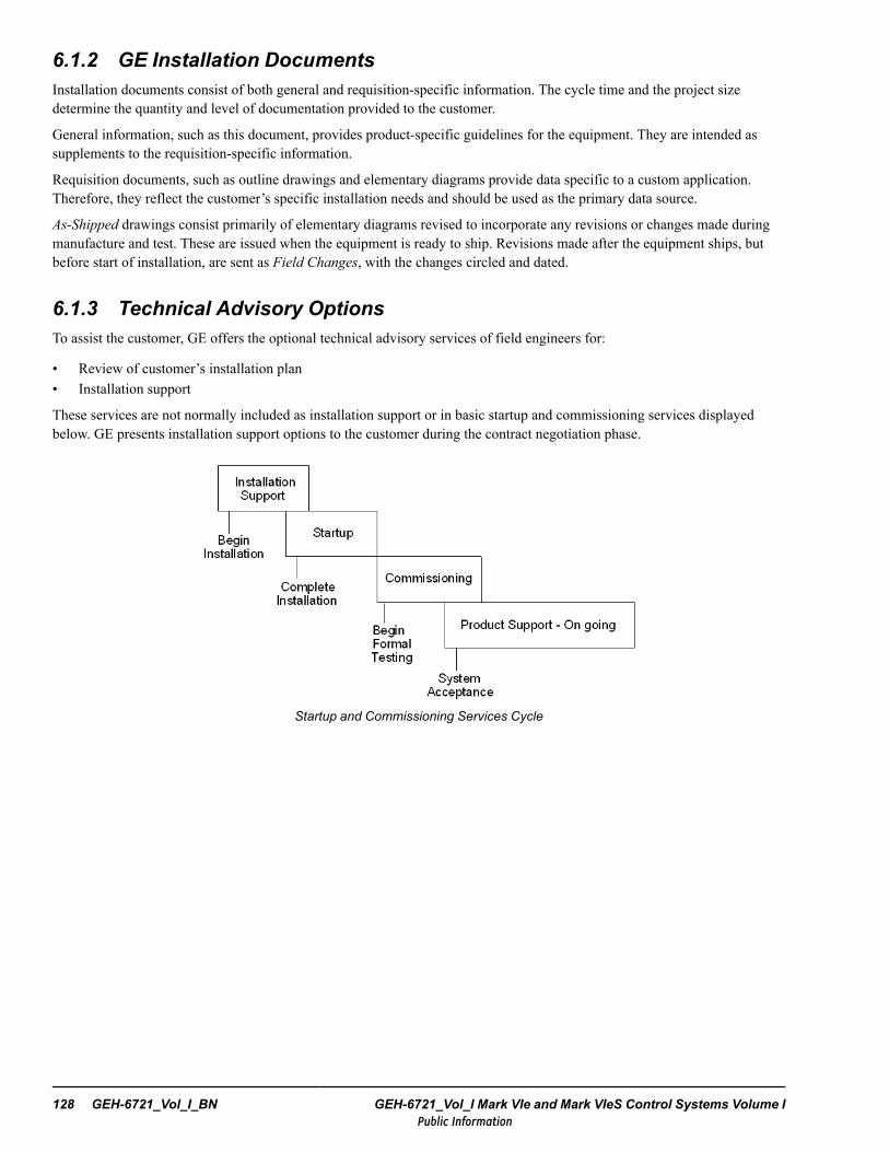
6.1.2 GE Installation DocumentsInstallation documents consist of both general and requisition-specific information. The cycle time and the project sizedetermine the quantity and level of documentation provided to the customer.
General information, such as this document, provides product-specific guidelines for the equipment. They are intended assupplements to the requisition-specific information.
Requisition documents, such as outline drawings and elementary diagrams provide data specific to a custom application.Therefore, they reflect the customer’s specific installation needs and should be used as the primary data source.
As-Shipped drawings consist primarily of elementary diagrams revised to incorporate any revisions or changes made duringmanufacture and test. These are issued when the equipment is ready to ship. Revisions made after the equipment ships, butbefore start of installation, are sent as Field Changes, with the changes circled and dated.
6.1.3 Technical Advisory OptionsTo assist the customer, GE offers the optional technical advisory services of field engineers for:
• Review of customer’s installation plan• Installation support
These services are not normally included as installation support or in basic startup and commissioning services displayedbelow. GE presents installation support options to the customer during the contract negotiation phase.
Startup and Commissioning Services Cycle
128 GEH-6721_Vol_I_BN GEH-6721_Vol_I Mark VIe and Mark VIeS Control Systems Volume IPublic Information
6.1.4 Installation Plan and SupportIt is recommended that a GE field representative review all installation/construction drawings and the cable and conduitschedule when completed. This optional review service ensures that the drawings meet installation requirements and arecomplete.
Optional installation support is offered: planning, practices, equipment placement, and onsite interpretation of constructionand equipment drawings. Engineering services are also offered to develop transition and implementation plans to install andcommission new equipment in both new and existing (revamp) facilities.
6.1.5 Customer’s Conduit and Cable ScheduleThe customer’s finished conduit and cable schedule should include:
• Interconnection wire list (optional)• Level definitions• Shield terminations
The cable and conduit schedule should define signal levels and classes of wiring (refer to the section, Cable Separation andRouting). This information should be listed in a separate column to help prevent installation errors.
The cable and conduit schedule should include the signal level definitions in the instructions. This provides all levelrestriction and practice information needed before installing cables.
The conduit and cable schedule should indicate shield terminal practice for each shielded cable (refer to the section,Connecting the System).
Installation Guidelines GEH-6721_Vol_I_BN System Guide 129Public Information
6.2 Equipment Receiving and HandlingGE inspects and packs all equipment before shipping it from the factory. A packing list, itemizing the contents of eachpackage, is attached to the side of each case.
Warning
Only personnel who are adequately trained and thoroughly familiar with theequipment and instructions should install, operate, or maintain the equipment. Toprevent damage to the equipment, personnel injury, or death, safe equipment liftingpractices must be followed. For example, use adequate tie-off, load-spreadingmechanisms, precise lifting control, managed acceleration, the correct forklift/cranerated for equipment tonnage, and so forth.
Upon receipt, carefully examine the contents of each shipment and check them with the packing list. Immediately report anyshortage, damage, or visual indication of rough handling to the carrier. Then notify both the transportation company and GE.Be sure to include the serial number, part (model) number, GE requisition number, and case number when identifying themissing or damaged part.
Attention
Immediately upon receiving the system, place it under adequate cover to protect itfrom adverse conditions. Packing cases are not suitable for outdoor or unprotectedstorage. Shock caused by rough handling can damage electrical equipment. To preventsuch damage when moving the equipment, observe normal precautions along with allhandling instructions printed on the case.
If technical assistance is required beyond the instructions provided in the documentation, contact the nearest GE Sales orService Office or an authorized GE Sales Representative.
Warning
Junction boxes can weigh well over 45.36 Kg (100 lb). Installation should be plannedto protect both the box and the personnel. The use of an overhead crane may berequired. Consult the site specific shipping and junction box documents. Follow allstandard safety practices.
Only personnel who are adequately trained and thoroughly familiar with theequipment and the instructions should install, operate, or maintain this equipment.
130 GEH-6721_Vol_I_BN GEH-6721_Vol_I Mark VIe and Mark VIeS Control Systems Volume IPublic Information
6.2.1 StorageIf the system is not installed immediately upon receipt, it must be stored properly to prevent corrosion and deterioration. Sincepacking cases do not protect the equipment for outdoor storage, the customer must provide a clean, dry place, free oftemperature variations, high humidity, and dust.
Use the following guidelines when storing the equipment:
• Place the equipment under adequate cover with the following requirements:− Keep the equipment clean and dry, protected from precipitation and flooding.− Use only breathable (canvas type) covering material – do not use plastic.
• Unpack the equipment as described, and label it.• Maintain the following environment in the storage enclosure:
− Recommended ambient storage temperature limits for the Mark VIe controller are from -40 to 85°C (-40 to 185 °F).− Surrounding air free of dust and corrosive elements, such as salt spray or chemical and electrically conductive
contaminants− Ambient relative humidity from 5 to 95% with provisions to prevent condensation− No rodents, snakes, birds or insects− No temperature variations that cause moisture condensation
Attention
Moisture on certain internal parts can cause electrical failure.
Condensation occurs with temperature drops of 15°C (59 °F) at 50% humidity over a four-hour period, and with smallertemperature variations at higher humidity.
If the storage room temperature varies in such a way, install a reliable heating system that keeps the equipment temperatureslightly above that of the ambient air. This can include space heaters or cabinet space heaters (when supplied) inside eachenclosure. A 100 W lamp can sometimes serve as a substitute source of heat.
Attention
To prevent fire hazard, remove all cartons and other such flammable materials packedinside units before energizing any heaters.
Installation Guidelines GEH-6721_Vol_I_BN System Guide 131Public Information

6.3 Power RequirementsThe control cabinet can accept power from multiple power sources. Each power input source (30 A / 120 Vac, 15 A / 240 Vac, or 30 A / 125 V dc) should feed through its own external, two-pole, thermal, magnetic circuit breaker before entering thecontrol system enclosure. The breaker should be supplied in accordance with required site codes. The circuit breaker must beincluded in the installation. If used as the panel disconnect, it must be suitably located and easily reachable. The circuitbreaker must be marked as the disconnecting device and suitably located near the equipment for servicing.
Mark VIe control systems may use up to three mains supplies; two for redundant control power (ac and / or dc) and oneauxiliary ac supply for accessories such as cabinet lights and fans. The following are example mains power supply ratinglabels used on the front cabinet door where the panel main power is to be connected.(100 [3.94])
(75 [2.95])
SIZ
ED
WG
NO
.S
HE
ET
RE
V
A10
9T74
282
A
©COPYRIGHT 2013 GE ENERGY (USA), LLC AND/OR ITS AFFILIATES. All rights reserved. The information contained herein is GE Energy C & PE COE Proprietary Technical Information that belongs to the General Electric Company, GE Energy (USA), LLC and/or their affiliates, which has been provided solely for the express reason of restricted private use. All persons, firms, or corporations who receive such information shall be deemed by the act of their receiving the same to have agreed to make no duplication, or other disclosure, or use whatsoever for any, or all such information except as expressly authorized in writing by the General Electric Company, GE Energy (USA), LLC and/or its affiliates.
GE CLASS II (INTERNAL CRITICAL)
GENERAL ELECTRIC COMPANY
GE Energy SALEM, VA.
GE PROPRIETARYINFORMATION
DATA NAMEPLATEMARK VI LINE
SIZE CAGE CODE DWG NO. REV
A 109T7428 ASCALE NONE SHEET 2 of 10
P0002
DWG Number 109T7428 Rev A Released 10/3/2013 Page 2 of 10
GE Proprietary Information - Class II (Internal) US EAR - NLR
(100 [3.94])
(75 [2.95])
SIZ
ED
WG
NO
.S
HE
ET
RE
V
A10
9T74
286
A
©COPYRIGHT 2013 GE ENERGY (USA), LLC AND/OR ITS AFFILIATES. All rights reserved. The information contained herein is GE Energy C & PE COE Proprietary Technical Information that belongs to the General Electric Company, GE Energy (USA), LLC and/or their affiliates, which has been provided solely for the express reason of restricted private use. All persons, firms, or corporations who receive such information shall be deemed by the act of their receiving the same to have agreed to make no duplication, or other disclosure, or use whatsoever for any, or all such information except as expressly authorized in writing by the General Electric Company, GE Energy (USA), LLC and/or its affiliates.
GE CLASS II (INTERNAL CRITICAL)
GENERAL ELECTRIC COMPANY
GE Energy SALEM, VA.
GE PROPRIETARYINFORMATION
DATA NAMEPLATEMARK VI LINE
SIZE CAGE CODE DWG NO. REV
A 109T7428 ASCALE NONE SHEET 6 of 10
P0006
DWG Number 109T7428 Rev A Released 10/3/2013 Page 6 of 10
GE Proprietary Information - Class II (Internal) US EAR - NLR
Referencing the designators from the rating label, AC1 and optional AC2 may be 120 Vac or 240 Vac, 50/60 Hz. DC1 andoptional DC2 are 220 V dc supplies that may be used instead of AC1 and AC2. DC is an optional floating source 125 V dcsupply, usually a battery. AUXAC is used only to supply internal auxiliary appliances, such as fans, heaters, lights, or socketoutlets. The AC1, AC2, DC, DC1, or DC2 mains supplies may feed one or more Switch Mode Power Supplies to provide 28V dc control power, or 24 or 48 V dc wetting for contact I/O circuits.
AC1 and AC2 may also feed one or two optional DACA Line Rectified Power Supplies. Each DACA is factory-set for either120 or 240 Vac input, and provides a floating 107 V dc output. The DACA DC output may be connected through an internaldiode with the DC optional 125 V dc supply to provide diode OR’d dc redundancy to feed Switch Mode Power Supplies,external loads such as solenoids, and /or wetting for contact I/O circuits.
Note To comply with Low Voltage Directive 2014/35/EU, all ac and dc power supply mains must connect through a MarkVIe Overvoltage Transient Protection and EMI Filter circuit. These OVand EMI filter circuits are built-in to the JPDB andJPDF Power Distribution Modules. If JPDB/JPDF are not used to distribute ac and dc power supply mains to the Mark VIecontrol, then a separate GE Filter Module 246B8279Gx should be used to filter the mains. Refer toMark VIe and Mark VIeSControl Systems Volume II: System Guide for General-purpose Applications (GEH-6721 Volume II), the chapter PDM PowerDistribution Modules.
132 GEH-6721_Vol_I_BN GEH-6721_Vol_I Mark VIe and Mark VIeS Control Systems Volume IPublic Information
Power requirements for a typical large, four-cabinet turbine control containing controllers, I/O, and terminal boards aredisplayed in the following table. The total cabinet current ratings must include the current supplied to external loads, such assolenoids and ignition transformers as described in the notes below the table. Heat dissipation in a typical TMR turbinecontrol is about 1600 watts. However, power supply mains and heat dissipation requirements must be calculated for eachMark VIe cabinet application based on the number and mix of controllers, I/O modules, IONet switches, power supplies, andexternal loading.
Power Requirements for Control Cabinets
Cabinet Voltage Frequency Current RequirementsLarge,four-cabinetturbine control
125 V dc120 V ac240 V ac
± 10%± 10%± 10%
N/A50/60 Hz50/60 Hz
N/A±3 Hz±3 Hz
15.0 A dc (Note 1)20.0 A rms (Notes 2, 4)10.0 A rms (Notes 3, 4)
1. Add 0.5 A dc † continuous for each 125 V dc external solenoid powered.
2. Add 6.0 A rms † for a continuously powered ignition transformer (2 maximum).
3. Add 3.5 A rms † for a continuously powered ignition transformer (2 maximum).
4. Add 2.0 A rms † continuous for each 120 V ac external solenoid powered (inrush 10 A).
Note † These are external and do not create cabinet heat load.
Installation Guidelines GEH-6721_Vol_I_BN System Guide 133Public Information
6.4 Installation Support DrawingsGE supplies the customer with site-specific documentation that can include a variety of drawings to display the equipmentinstalled at site. Drawings are typically B-size AutoCAD®, and can include the following:
• System Topology (4108)• Cabinet Outline• Cabinet Layout• Circuit Diagram
Note An I/O Report can be generated from the ToolboxST application.
6.5 GroundingThis section defines grounding and signal-referencing practices for the control system. This can be used to check for propergrounding and signal reference structure (SRS) after the equipment is installed. If checking the equipment after the powercable has been connected or after power has been applied to the cabling, be sure to follow all safety precautions for workingaround high voltages.
Warning
To prevent electric shock, make sure that all power supplies to the equipment areturned off. Then discharge and ground the equipment before performing any actrequiring physical contact with the electrical components or wiring. If test equipmentcannot be grounded to the equipment under test, the test equipment's case must beshielded to prevent contact by personnel. Be sure to follow the site LOTO and safetypractices.
6.5.1 Equipment GroundingEquipment grounding and signal referencing have two distinct purposes:
• Equipment grounding protects personnel from risk of serious or fatal electrical shock, burn, fire, and/or other damage toequipment caused by ground faults or lightning.
• Signal referencing helps protect equipment from the effects of internal and external electrical noise, such as lightning orswitching surges.
Installation practices must simultaneously comply with all codes in effect at the time and place of installation, and with allpractices that improve the immunity of the installation. Code requirements for safety of personnel and equipment must takeprecedence in the case of any conflict with noise control practices.
Note In addition to technical regulations, guidance from IEEE Std 142-2007 IEEE Recommended Practice for Grounding ofIndustrial and Commercial Power Systems, and IEEE Std 1100-2005 IEEE Recommended Practice for Powering andGrounding Electronic Equipment are provided by the design and implementation of the system.
134 GEH-6721_Vol_I_BN GEH-6721_Vol_I Mark VIe and Mark VIeS Control Systems Volume IPublic Information
The control system has no special or non-standard installation requirements, if installed in compliance with all of thefollowing:
• The NEC or local codes• With SRS designed to meet IEEE Std 1100• Interconnected with signal/power-level separation as defined later
This section provides equipment grounding and bonding guidelines for control and I/O cabinets. These guidelines also applyto motors, transformers, brakes, and reactors. Each of these devices should have its own grounding conductor going directlyto the building ground grid.
• Ground each cabinet or cabinet lineup to the equipment ground at the source of power feeding it.− See NEC Article 250 for sizing and other requirements for the equipment-grounding conductor.− For dc circuits only, the NEC allows the equipment-grounding conductor to be run separate from the circuit
conductors.• With certain restrictions, the NEC allows the metallic raceways or cable trays containing the circuit conductors to serve
as the equipment grounding conductor:− This use requires that they form a continuous, low-impedance path capable of conducting anticipated fault current.− This use requires bonding across loose-fitting joints and discontinuities. See NEC Article 250 for specific bonding
requirements. This chapter includes recommendations for high-frequency bonding methods.− If metallic raceways or cable trays are not used as the primary equipment- grounding conductor, they should be used
as a supplementary equipment grounding conductor. This enhances the safety of the installation and improves theperformance of the SRS.
• The equipment-grounding connection for the control cabinets is plated copper bus or stub bus. This connection is bondedto the cabinet enclosure using bolting that keeps the conducting path’s resistance at 1 ohm or less.
• There should be a bonding jumper across the ground bus or floor sill between all shipping splits. The jumper may be aplated metal plate.
• The non-current carrying metal parts of the equipment covered by this section should be bonded to the metallic supportstructure or building structure supporting this equipment. The equipment mounting method may satisfy this requirement.If supplementary bonding conductors are required, size them the same as equipment-grounding conductors.
6.5.2 Building Grounding SystemThis section provides guidelines for the building grounding system requirements. For specific requirements, refer to NECarticle 250 under the heading Grounding Electrode System.
The guidelines below are for metal-framed buildings. For non-metal framed buildings, consult the GE factory.
The ground electrode system should be composed of steel reinforcing bars in building column piers bonded to the majorbuilding columns.
• A buried ground ring should encircle the building. This ring should be interconnected with the bonding conductorrunning between the steel reinforcing bars and the building columns.
• All underground, metal water piping should be bonded to the building system at the point where the piping crosses theground ring.
• NEC Article 250 requires that separately derived systems (transformers) be grounded to the nearest effectively groundedmetal building structural member.
• Braze or exothermically weld all electrical joints and connections to the building structure, where practical. This type ofconnection keeps the required good electrical and mechanical properties from deteriorating over time.
Installation Guidelines GEH-6721_Vol_I_BN System Guide 135Public Information
6.5.3 Signal Reference StructureOn modern equipment communicating at high bandwidths, signals are typically differential and/or isolated electrically oroptically. The modern Signal Reference Structure (SRS) system replaces the older single-point grounding system with a muchmore robust system. The SRS system is also easier to install and maintain.
Note The provisions covered in this document may not apply to all installations.
The goal of the SRS is to hold the electronics at or near case potential to prevent unwanted signals from disturbing operation.The following conditions must all be met by an SRS:
• Bonding connections to the SRS must be less than 1/20 wavelength of the highest frequency to which the equipment issusceptible. This prevents standing waves. In modern equipment using high-frequency digital electronics, frequencies ashigh as 500 MHz should be considered. This translates to about 30 mm (1 in).
• SRS must be a good high-frequency conductor. (Impedance at high frequencies consists primarily of distributedinductance and capacitance.) Surface area is more important than cross-sectional area because of skin effect.Conductivity is less important (steel with large surface area is better than copper with less surface area).
• SRS must consist of multiple paths. This lowers the impedance and the probability of wave reflections and resonance
In general, a good signal referencing system can be obtained with readily available components in an industrial site. All of theitems listed below can be included in an SRS:
• Metal building structural members• Galvanized steel floor decking under concrete floors• Woven wire steel reinforcing mesh in concrete floors• Steel floors in pulpits and power control rooms• Bolted grid stringers for cellular raised floors• Steel floor decking or grating on line-mounted equipment• Galvanized steel culvert stock• Ferrous metallic cable tray systems• Raceway (cableway) and raceway support systems• Embedded steel floor channels
Connection of the Protective Earth (PE) terminal to the installation ground system must first comply with code requirementsand second provide a low-impedance path for high-frequency currents, including lightning surge currents. This groundingconductor must not provide, either intentionally or inadvertently, a path for load current. The system should be designed sothat there is no way possible for the control system to be an attractive path for induced currents from any source. This is bestaccomplished by providing a ground plane that is large and low impedance, so that the entire system remains at the samepotential. A metallic system (grid) will accomplish this much better than a system that relies upon earth for connection. At thesame time all metallic structures in the system should be effectively bonded both to the grid and to each other, so that bondingconductors rather than control equipment become the path of choice for noise currents of all types.
In the control cabinet, the base is insulated from the chassis and bonded at one point. The grounding recommendations call forthe equipment grounding conductor to be 120 mm2 (4/0 AWG) gauge wire of shortest possible length connected to the nearestpoint of building ground system. PE plated copper bus to Earth pit/connection point resistance should be 1 Ohm or less. TheFunctional Earth (FE) is bonded at one point to the PE ground using two 25 mm2 (6 AWG or larger) green/yellow bondingjumpers. These grounding recommendations are illustrated in the following figure.
136 GEH-6721_Vol_I_BN GEH-6721_Vol_I Mark VIe and Mark VIeS Control Systems Volume IPublic Information
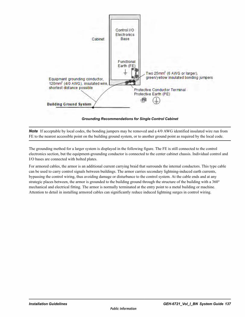
Grounding Recommendations for Single Control Cabinet
Note If acceptable by local codes, the bonding jumpers may be removed and a 4/0 AWG identified insulated wire run fromFE to the nearest accessible point on the building ground system, or to another ground point as required by the local code.
The grounding method for a larger system is displayed in the following figure. The FE is still connected to the controlelectronics section, but the equipment-grounding conductor is connected to the center cabinet chassis. Individual control andI/O bases are connected with bolted plates.
For armored cables, the armor is an additional current carrying braid that surrounds the internal conductors. This type cablecan be used to carry control signals between buildings. The armor carries secondary lightning-induced earth currents,bypassing the control wiring, thus avoiding damage or disturbance to the control system. At the cable ends and at anystrategic places between, the armor is grounded to the building ground through the structure of the building with a 360°mechanical and electrical fitting. The armor is normally terminated at the entry point to a metal building or machine.Attention to detail in installing armored cables can significantly reduce induced lightning surges in control wiring.
Installation Guidelines GEH-6721_Vol_I_BN System Guide 137Public Information
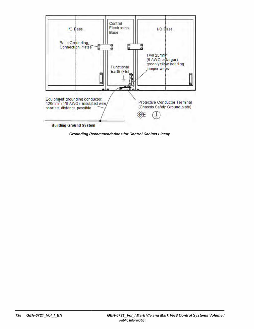
Grounding Recommendations for Control Cabinet Lineup
138 GEH-6721_Vol_I_BN GEH-6721_Vol_I Mark VIe and Mark VIeS Control Systems Volume IPublic Information

6.5.3.1 Grounding NotesBonding to building structure - The cable tray support system typically provides many bonding connections to buildingstructural steel. If this is not the case, supplemental bonding connections must be made at frequent intervals from the cabletray system to building steel.
Connected equipment - Cable tray installations for connected equipment should pay special attention to goodhigh-frequency bonding between the cable tray and the equipment.
Cable spacing - Maintain cable spacing between signal levels in cable drops, as recommended in the section CableSeparation and Routing.
Conduit sleeves - Where conduit sleeves are used for bottom-entry cables, the sleeves should be bonded to the floor deckingand equipment enclosure with short bonding jumpers.
Embedded conduits - Bond all embedded conduits to the enclosure with multiple bonding jumper connections following theshortest possible path.
Galvanized steel sheet floor decking - Floor decking can serve as a high-frequency signal reference plane for equipmentlocated on upper floors. With typical building construction, there will be a large number of structural connections between thefloor decking and building steel. If this is not the case, then an electrical bonding connection must be added between the floordecking and building steel. The added connections need to be as short as possible and of sufficient surface area to be lowimpedance at high frequencies.
High-frequency bonding jumpers - Jumpers must be short, less than 500 mm (20 in) and good high-frequency conductors.Thin, wide metal strips are best with length not more than three times width for best performance. Jumpers can be copper,aluminum, or steel. Steel has the advantage of not creating galvanic half-cells when bonded to other steel parts.
Jumpers must make good electrical contact with both the enclosure and the signal reference structure. Welding is best. If amechanical connection is used, each end should be fastened with two bolts or screws with star washers backed up by largediameter flat washers.
Each enclosure must have two bonding jumpers of short, random lengths. Random lengths are used so that parallel bondingpaths are of different quarter wavelength multiples. Do not fold bonding jumpers or make sharp bends.
Metallic cable tray - System must be installed per NEC Article 318 with signal level spacing per the section, CableSeparation and Routing. This serves as a signal reference structure between remotely connected pieces of equipment. Thelarge surface area of cable trays provides a low impedance path at high frequencies.
Metal framing channel - Metal framing channel cable support systems also serve as parts of the SRS. Make certain thatchannels are well bonded to the equipment enclosure, cable tray, and each other, with large surface area connections toprovide low impedance at high frequencies.
Noise-sensitive cables - Try to run noise-sensitive cables tight against a vertical support to allow this support to serve as areference plane. Cables that are extremely susceptible to noise should be run in a metallic conduit, preferably ferrous. Keepthese cables tight against the inside walls of the metallic enclosure, and well away from higher-level cables.
Power cables - Keep single-conductor power cables from the same circuit tightly bundled together to minimize interferencewith nearby signal cables. Keep 3-phase ac cables in a tight triangular configuration.
Woven wire mesh - Woven wire mesh can serve as a high-frequency signal reference grid for enclosures located on floors notaccessible from below. Each adjoining section of mesh must be welded together at intervals not exceeding 500 mm (20 in) tocreate a continuous reference grid. The woven wire mesh must be bonded at frequent intervals to building structural membersalong the floor perimeter.
Conduit terminal at cable trays - To provide the best shielding, conduits containing level L cables (see Leveling channels)should be terminated to the tray's side rails (steel solid bottom) with two locknuts and a bushing. Conduit should beterminated to ladder tray side rails with approved clamps.
Where it is not possible to connect conduit directly to tray (such as with large conduit banks), conduit must be terminated withbonding bushings and bonded to tray with short bonding jumpers.
Installation Guidelines GEH-6721_Vol_I_BN System Guide 139Public Information
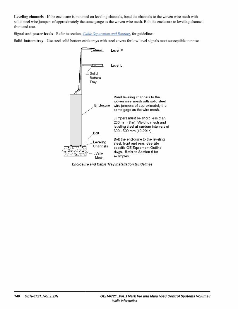
Leveling channels - If the enclosure is mounted on leveling channels, bond the channels to the woven wire mesh withsolid-steel wire jumpers of approximately the same gauge as the woven wire mesh. Bolt the enclosure to leveling channel,front and rear.
Signal and power levels - Refer to section, Cable Separation and Routing, for guidelines.
Solid-bottom tray - Use steel solid bottom cable trays with steel covers for low-level signals most susceptible to noise.
Enclosure and Cable Tray Installation Guidelines
140 GEH-6721_Vol_I_BN GEH-6721_Vol_I Mark VIe and Mark VIeS Control Systems Volume IPublic Information
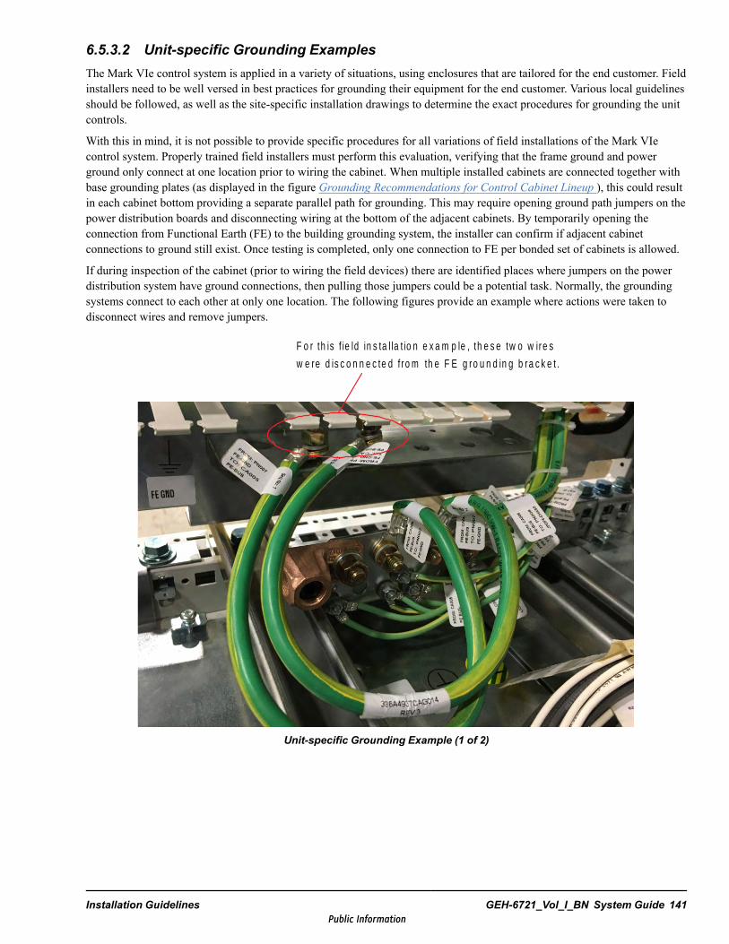
6.5.3.2 Unit-specific Grounding ExamplesThe Mark VIe control system is applied in a variety of situations, using enclosures that are tailored for the end customer. Fieldinstallers need to be well versed in best practices for grounding their equipment for the end customer. Various local guidelinesshould be followed, as well as the site-specific installation drawings to determine the exact procedures for grounding the unitcontrols.
With this in mind, it is not possible to provide specific procedures for all variations of field installations of the Mark VIecontrol system. Properly trained field installers must perform this evaluation, verifying that the frame ground and powerground only connect at one location prior to wiring the cabinet. When multiple installed cabinets are connected together withbase grounding plates (as displayed in the figure Grounding Recommendations for Control Cabinet Lineup ), this could resultin each cabinet bottom providing a separate parallel path for grounding. This may require opening ground path jumpers on thepower distribution boards and disconnecting wiring at the bottom of the adjacent cabinets. By temporarily opening theconnection from Functional Earth (FE) to the building grounding system, the installer can confirm if adjacent cabinetconnections to ground still exist. Once testing is completed, only one connection to FE per bonded set of cabinets is allowed.
If during inspection of the cabinet (prior to wiring the field devices) there are identified places where jumpers on the powerdistribution system have ground connections, then pulling those jumpers could be a potential task. Normally, the groundingsystems connect to each other at only one location. The following figures provide an example where actions were taken todisconnect wires and remove jumpers.
F o r th is f ie ld in s ta l la t io n e x a m p le , th e s e tw o w ire s
w e re d is c o n n e c te d f r o m th e F E g ro u n d in g b ra c k e t .
Unit-specific Grounding Example (1 of 2)
Installation Guidelines GEH-6721_Vol_I_BN System Guide 141Public Information
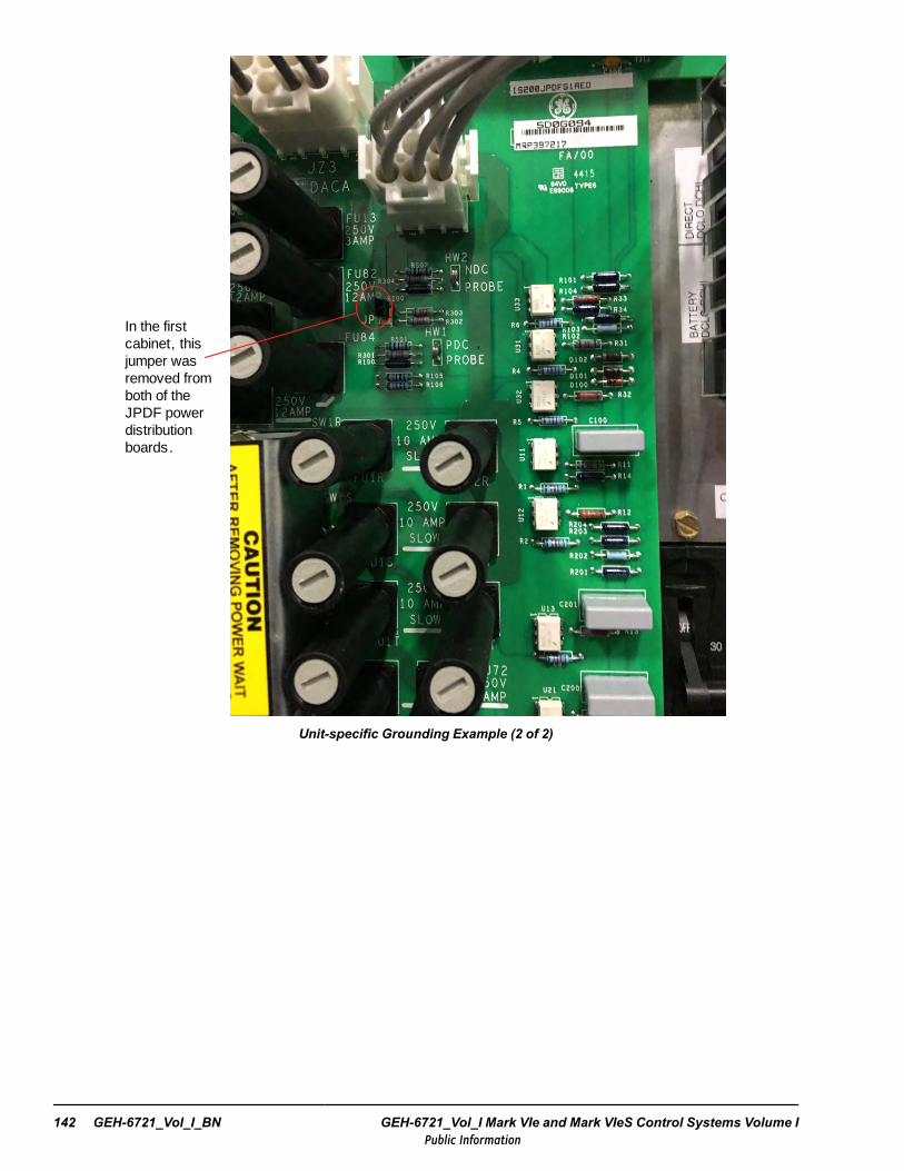
In the first cabinet, this jumper was removed from both of the JPDF power distribution boards.
Unit-specific Grounding Example (2 of 2)
142 GEH-6721_Vol_I_BN GEH-6721_Vol_I Mark VIe and Mark VIeS Control Systems Volume IPublic Information

6.6 Cable Separation and RoutingThis section provides recommended cabling practices to reduce electrical noise. These practices include signal/power levelseparation and cable routing guidelines.
Note Electrical noise from cabling of various voltage levels can interfere with microprocessor-based control systems,causing a malfunction. If a situation at the installation site is not covered in this document, or if these guidelines cannot bemet, please contact GE before installing the cable.
Early planning enables the customer’s representatives to design adequate separation of embedded conduit. On newinstallations, sufficient space should be allowed to efficiently arrange mechanical and electrical equipment. On revamps, levelrules should be considered during the planning stages to help ensure correct application and a more trouble-free installation.
6.6.1 Signal and Power Level DefinitionsSignal and power carrying cables are categorized into four defining levels; low, medium, high, and power. Each level caninclude classes.
6.6.1.1 Low-level Signals (Level L)Low-level signals are designated as level L. In general these consist of:
• Analog signals 0 through ±50 V dc, < 60 mA• Digital (logic-level) signals less than 28 V dc• 4 to 20 mA current loops• Ac signals less than 24 Vac
The following are specific examples of level L signals used in the control cabling:
Note Signal input to analog and digital blocks or to programmable logic control (PLC)-related devices should be run asshielded twisted-pair (for example, input from RTDs).
• All analog and digital signals including LVDTs, Servos, RTDs, Analog Inputs and Outputs, and Pyrometer signals• Thermocouples are in a special category (Level LS) because they generate millivolt signals with very low current.• Network communication bus signals: Ethernet, IONet, UDH, PDH, RS-232C, and RS-422• Phone circuits
Installation Guidelines GEH-6721_Vol_I_BN System Guide 143Public Information
6.6.1.2 Medium-level Signals (Level M)Medium-level signals are designated as level M. MPU signals are examples of level M signals used in the controller. Thesesignals consist of:
• Analog signals less than 50 V dc with less than 28 Vac ripple and less than 0.6 A current• 28 V dc light and switching circuits• 24 V dc switching circuits• Analog pulse rate circuits
Note Level M and level L signals may be run together only inside the control cabinet.
6.6.1.3 High-level Signals (Level H)High-level signals are designated as level H. These signals consist of:
• Dc switching signals greater than 28 V dc• Analog signals greater than 50 V dc with greater than 28 Vac ripple• Ac feeders less than 20 A, without motor loads
The following are specific examples of level H signals used in cabling:
• Contact inputs• Relay outputs• Solenoid outputs• Potential transformer (PT) and current transformer (CT) circuits
Note Flame detector (GM) type signals, 335 V dc, and Ultraviolet detectors are a special category (Level HS). Special lowcapacitance twisted shielded pair wiring is required.
6.6.1.4 Power (Level P)Power wiring is designated as level P. This consists of ac and dc buses 0 – 600 V with currents 20 A – 800 A. The followingare specific examples of level P signals used in plant cabling:
• Motor armature loops• Generator armature loops• Ac power input and dc outputs• Primary and secondary wiring of transformers above 5 kVA• SCR field exciter ac power input and dc output• Static exciters (regulated and unregulated) ac power and dc output• 250 V shop bus• Machine fields
144 GEH-6721_Vol_I_BN GEH-6721_Vol_I Mark VIe and Mark VIeS Control Systems Volume IPublic Information
6.6.1.5 Class CodesCertain conditions can require that specific wires within a level be grouped in the same cable. This is indicated by class codes,defined as follows:
S Special handling of specified levels can require special spacing of conduit and trays. Check dimension chart for levels.These wires include:
• Signals from COMM field and line resistors• Signals from line shunts to regulators
U High voltage potential unfused wires over 600 V dc
PS Power greater than 600 V dc and/or greater than 800 A
If there is no class code, there are no grouping restrictions within designated levels
6.6.1.6 Marking Cables to Identify LevelsMark the cableway cables, conduit, and trays in a way that clearly identify their signal/power levels. This helps ensure correctlevel separation for proper installation. It can also be useful during equipment maintenance.
Cables can be marked by any means that makes the level easy to recognize (for example, coding or numbering). Conduit andtrays should be marked at junction points or at periodic intervals.
6.6.2 Cableway Spacing GuidelinesSpacing (or clearance) between cableways (trays and conduit) depends on the level of the wiring inside them. For correctlevel separation when installing cable, the customer should apply the general practices along with the specific spacing valuesfor tray/tray, conduit/tray, conduit/conduit, cable/conduit, and cable/cable distances as discussed below.
Installation Guidelines GEH-6721_Vol_I_BN System Guide 145Public Information
6.6.2.1 General PracticesThe following general practices should be used for all levels of cabling:
• All cables of like signal levels and power levels must be grouped together in like cableways.• In general, different levels must run in separate cableways, as defined in the different levels. Intermixing cannot be
allowed, except as noted by exception.• Interconnecting wire runs should carry a level designation.• If wires are the same level and same type signal, group those wires from one cabinet to any one specific location together
in multiconductor cables.• When unlike signals must cross in trays or conduit, cross them in 90° angles at maximum spacing. Where it is not
possible to maintain spacing, place a grounded steel barrier between unlike levels at the crossover point.• When entering terminal equipment where it is difficult to maintain the specific spacing guidelines displayed in the
following tables, keep parallel runs to a minimum, not to exceed 1.5 m (5 ft) in the overall run.• Where the tables display tray or conduit spacing as 0, the levels can be run together. Spacing for other levels must be
based on the worst condition.• Trays for all levels should be solidly grounded with good ground continuity. Conduit should provide shielding.
The following general practices should be used for specific levels of cabling:
• When separate trays are impractical, levels L and M can be combined in a common tray if a grounded steel barrierseparates levels. This practice is not as effective as tray separation, and may require some rerouting at system startup. Iflevels L and M are run side-by-side, a 50 mm (1.97 in) minimum spacing is recommended.
• Locate levels L and M trays and conduit closest to the control cabinets.• Trays containing level L and level M wiring should have solid galvanized steel bottoms and sides and be covered to
provide complete shielding. There must be positive and continuous cover contact to side rails to avoid high-reluctance airgaps, which impair shielding.
• Trays containing levels other than L and M wiring can have ventilation slots or louvers.• Trays and conduit containing levels L, M, and H(S) should not be routed parallel to high power equipment enclosures of
100 kVand larger at a spacing of less than 1.5 m (5 ft) for trays, and 750 mm (2.5 ft) for conduit.• Level H and H(S) can be combined in the same tray or conduit but cannot be combined in the same cable.• Level H(S) is listed only for information since many customers want to isolate unfused high voltage potential wires.• Do not run levels H and H(S) in the same conduit as level P.• Where practical for level P and/or P(S) wiring, route the complete power circuit between equipment in the same tray or
conduit. This minimizes the possibility of power and control circuits encircling each other.
146 GEH-6721_Vol_I_BN GEH-6721_Vol_I Mark VIe and Mark VIeS Control Systems Volume IPublic Information
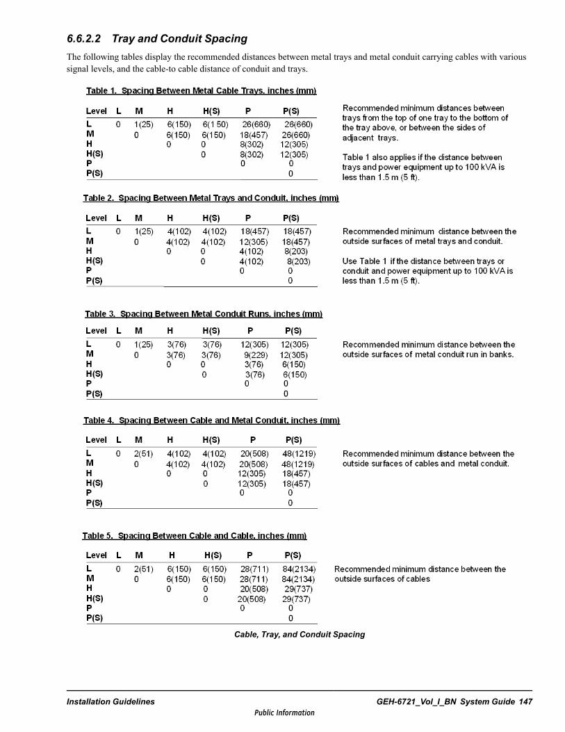
6.6.2.2 Tray and Conduit SpacingThe following tables display the recommended distances between metal trays and metal conduit carrying cables with varioussignal levels, and the cable-to cable distance of conduit and trays.
Cable, Tray, and Conduit Spacing
Installation Guidelines GEH-6721_Vol_I_BN System Guide 147Public Information
6.6.3 Cable Routing Guidelines
6.6.3.1 Pullboxes and Junction BoxesKeep signal and power levels separate inside pullboxes and junction boxes. Use grounded steel barriers to maintain levelspacing. Tray-to-conduit transition spacing and separation are a potential source of noise. Be sure to cross unlike levels atright angles and maintain required separation. Use level spacing. Protect transition areas according to the level spacingrecommendations.
6.6.3.2 Transitional AreasWhen entering or leaving conduit or trays, ensure cables of unlike levels are not mixed. If the installation needs parallel runsover 1.5 m (5 ft), grounded steel barriers may be needed for proper level separation.
6.6.3.3 Cabling for RetrofitsReducing electrical noise on retrofits requires careful planning. Lower and higher levels should never encircle each other orrun parallel for long distances. It is practical to use existing conduit or trays as long as the level spacing can be maintained forthe full length of the run. Existing cables are generally of high voltage potential and noise producing. Therefore, route levelsL and M in a path apart from existing cables when possible. Use barriers in existing pullboxes and junction boxes for level Lwiring to minimize noise potential. Do not loop level L signals around high control or level P conduit or trays.
6.6.3.4 Conduit Around and Through Machinery HousingCare should be taken to plan level spacing on both embedded and exposed conduit in and around machinery. Runs containingmixed levels should be minimized to 1.5 m (5 ft) or less overall. Conduit running through and attached to machinery housingshould follow level spacing recommendations. This should be discussed with the contractor early in the project.
Trunnions entering floor mounted operator station cabinets should be kept as short as possible when used as cableways. Thishelps minimize parallel runs of unlike levels to a maximum of 1.5 m (5 ft) before entering the equipment. Where differentsignal/power levels are running together for short distances, each level should be connected by cord ties, barriers, or somelogical method to prevent intermixing.
6.6.3.5 RF InterferenceTo prevent radio frequency (RF) interference, take care when routing power cables near radio-controlled devices (forexample, cranes) and audio/visual systems (public address and closed-circuit television systems).
6.6.3.6 SuppressionUnless specifically noted otherwise, suppression (for example, a snubber) is required on all inductive devices controlled by anoutput. This suppression minimizes noise and prevents damage caused by electrical surges. Standard relay and solenoidoutput boards have adequate suppression.
148 GEH-6721_Vol_I_BN GEH-6721_Vol_I Mark VIe and Mark VIeS Control Systems Volume IPublic Information

6.7 Power and I/O Field Wiring
6.7.1 General Requirements• Maximum length (unless specified) 300 m (984.25 ft)• Individual minimum stated wire size is for electrical needs• Clamp-type terminals accept two 14 AWG wires or one 12 AWG wire• Terminal blocks accept two 12 AWG wires• PTs and CTs use 10 AWG stranded wire
Note Wires with appropriate temperature ratings must be used, especially in applications where the internal cabinet ambienttemperature can exceed 60°C (140 °F).
It is standard practice to use shielded cable with control equipment. Shielding provides the following benefits:
• Generally, shielding protects a wire or combination of wires from its environment.• Low-level signals may require shielding to prevent signal interference due to the capacitive coupling effect between two
sources of potential energy.
6.7.2 I/O Field Wiring RestrictionsBoard LimitationTBAI 15 Ω maximum two-way cable resistance, cable length up to 300 m (984 ft)
STAI 15 Ω maximum two-way cable resistance, cable length up to 300 m (984 ft)
SAII 15 Ω maximum two-way cable resistance, cable length up to 300 m (984 ft)
TBAO Driven devices should not exceed a resistance of 900 Ω and can be located up to 300 m (984 ft) from the control cabinet
STAO Driven devices should not exceed a resistance of 900 Ω and can be located up to 300 m (984 ft) from the control cabinet
PCNO CANopen cable limits are defined by the standard. GEH-6721_Vol_II provides and a table with baud rate to maximum distances
PFFA Foundation Fieldbus standards for cabling apply
SHRA 15 Ω maximum two-way cable resistance, cable length up to 300 m (984 ft)
PPRF GEH-6721_Vol_II provides a summary of Profibus cable requirements including a bus length vs. data rate table
PRTDThe eight RTDs can be located up to 300 meters (984 feet) from the distributed I/O cabinet with a maximum two-way cableresistance of 15 Ω
PSCA GEH-6721_Vol_II lists cable distance and maximum baud rate for the three supported communication standards
PTCCThermocouples can be located up to 300 meters (984 feet) from the turbine I/O panel with a maximum two-way cable resistance of450 Ω
PVIB Often sensors used with this input module impose their own cabling requirements
PAMC Often sensors used with this input module impose their own cabling requirements
PCLA
For thermocouples- 450 Ω maximum two-way cable resistance, cable length up to 300 m (984 ft)For analog inputs- 15 Ω maximum two-way cable resistance, cable length up to 300 m (984 ft)Other signals do not list a cable specification so the product level requirement applies
PPRA RS232 and RS485 standards are invoked for speed repeater output signals
PPRO V3 383 TPRO and 388 SPRO for voltage sensing limits cable length up to 1,000 ft. of 18 AWG wiring
PSCH GEH-6721_Vol_II provides cable distance and maximum baud rate for the three supported communication standards
Installation Guidelines GEH-6721_Vol_I_BN System Guide 149Public Information
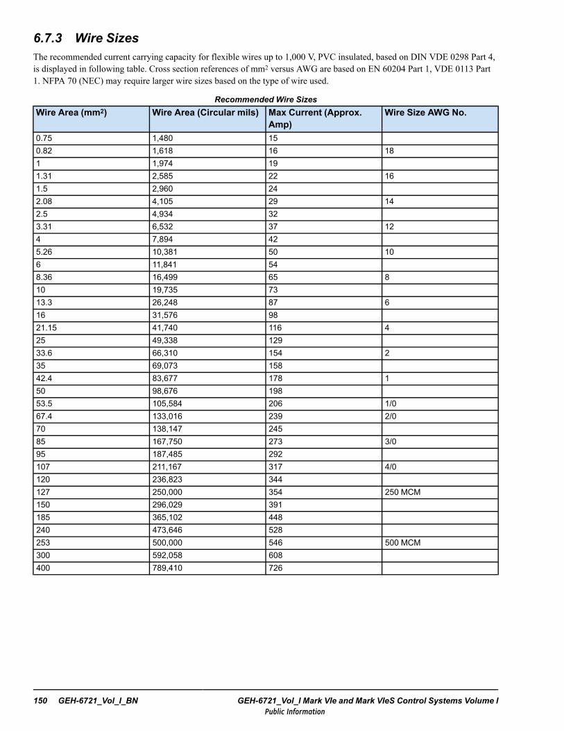
6.7.3 Wire SizesThe recommended current carrying capacity for flexible wires up to 1,000 V, PVC insulated, based on DIN VDE 0298 Part 4,is displayed in following table. Cross section references of mm2 versus AWG are based on EN 60204 Part 1, VDE 0113 Part1. NFPA 70 (NEC) may require larger wire sizes based on the type of wire used.
Recommended Wire SizesWire Area (mm2) Wire Area (Circular mils) Max Current (Approx.
Amp)Wire Size AWG No.
0.75 1,480 150.82 1,618 16 181 1,974 191.31 2,585 22 161.5 2,960 242.08 4,105 29 142.5 4,934 323.31 6,532 37 124 7,894 425.26 10,381 50 106 11,841 548.36 16,499 65 810 19,735 7313.3 26,248 87 616 31,576 9821.15 41,740 116 425 49,338 12933.6 66,310 154 235 69,073 15842.4 83,677 178 150 98,676 19853.5 105,584 206 1/067.4 133,016 239 2/070 138,147 24585 167,750 273 3/095 187,485 292107 211,167 317 4/0120 236,823 344127 250,000 354 250 MCM150 296,029 391185 365,102 448240 473,646 528253 500,000 546 500 MCM300 592,058 608400 789,410 726
150 GEH-6721_Vol_I_BN GEH-6721_Vol_I Mark VIe and Mark VIeS Control Systems Volume IPublic Information
6.7.4 Low-voltage Shielded Power CablesThis section defines the minimum requirements for low-voltage shielded cable. These guidelines should be used along withthe level practices and routing guidelines provided previously.
Note The specifications listed are for sensitive computer-based controls. Cabling for less sensitive controls should beconsidered on an individual basis.
6.7.4.1 Single-conductor Shielded Cable, Rated 300 V
• 18 AWG minimum, stranded single-conductor insulated with minimum 85% to 100% coverage shield• Protective insulating cover for shield• Wire rating: 300 V minimum• Maximum capacitance between conductor and shield: 492 pF/m (150 pF/ft)
6.7.4.2 Multi-conductor Shielded Cable, Rated 300 V
• 18 AWG minimum, stranded conductors individually insulated per cable with minimum 85 to 100% coverage shield• Protective insulating cover for shield• Wire rating: 300 V minimum• Mutual capacitance between conductors with shield grounded: 394 pF/m (120 pF/ft) maximum• Capacitance between one conductor and all other conductors and grounded shield: 213 pF/m (65 pF/ft)
6.7.4.3 Shielded Twisted Pair (STP) Cable, Rated 300 V
• Two 18 AWG minimum, stranded conductors individually insulated with minimum 85 to 100% coverage shield• Protective insulating cover for shield• Wire rating: 300 V minimum• Mutual capacitance between conductors with shield grounded: 394 pF/m (120 pF/ft) maximum• Capacitance between one conductor and the other conductor and grounded shield: 213 pF/m (65 pF/ft) maximum
6.7.4.4 Instrument Cable, 4 – 20 mA
• With Tefzel® insulation and jacket: Belden® catalog number. 85231 or equivalent• With plastic jacket: Belden catalog number 9316 or equivalent
Installation Guidelines GEH-6721_Vol_I_BN System Guide 151Public Information
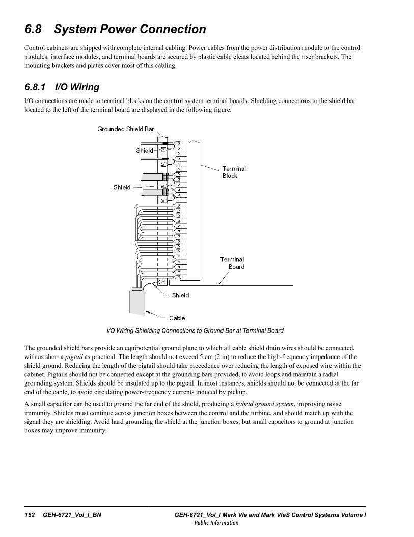
6.8 System Power ConnectionControl cabinets are shipped with complete internal cabling. Power cables from the power distribution module to the controlmodules, interface modules, and terminal boards are secured by plastic cable cleats located behind the riser brackets. Themounting brackets and plates cover most of this cabling.
6.8.1 I/O WiringI/O connections are made to terminal blocks on the control system terminal boards. Shielding connections to the shield barlocated to the left of the terminal board are displayed in the following figure.
I/O Wiring Shielding Connections to Ground Bar at Terminal Board
The grounded shield bars provide an equipotential ground plane to which all cable shield drain wires should be connected,with as short a pigtail as practical. The length should not exceed 5 cm (2 in) to reduce the high-frequency impedance of theshield ground. Reducing the length of the pigtail should take precedence over reducing the length of exposed wire within thecabinet. Pigtails should not be connected except at the grounding bars provided, to avoid loops and maintain a radialgrounding system. Shields should be insulated up to the pigtail. In most instances, shields should not be connected at the farend of the cable, to avoid circulating power-frequency currents induced by pickup.
A small capacitor can be used to ground the far end of the shield, producing a hybrid ground system, improving noiseimmunity. Shields must continue across junction boxes between the control and the turbine, and should match up with thesignal they are shielding. Avoid hard grounding the shield at the junction boxes, but small capacitors to ground at junctionboxes may improve immunity.
152 GEH-6721_Vol_I_BN GEH-6721_Vol_I Mark VIe and Mark VIeS Control Systems Volume IPublic Information
6.9 Startup ChecksAll control system panels have cables pre-installed and factory-tested before shipment. However, final checks should be madeafter installation and before starting the equipment.
Warning
This equipment contains a potential hazard of electrical shock or burn. Power isprovided by the control system to various input and output devices. External sourcesof power may be present in the control system that are NOT switched by the controlpower circuit breaker(s). Before handling or connecting any conductors to theequipment, use proper safety precautions to ensure all power is turned off.
Inspect the cabinet components for any damage possibly occurring during shipping. Check for loose cables, wires,connections, or loose components, such as relays or retainer clips. Report all damage that occurred during shipping to GEProduct Service.
Attention
Deposits containing ionic contaminants such as salt are difficult to remove completely,and may combine with moisture to cause irreparable damage to the boards.
Installation Guidelines GEH-6721_Vol_I_BN System Guide 153Public Information

6.9.1 Power Wiring and Circuit ChecksThe 125 V dc supply must be installed and maintained so that it meets requirements of IEC 61010-1 cl. 6.3.1 to be consideredNot Hazardous Live. The BJS berg jumper must be installed in the JPDF to provide the monitored ground reference for the125 V dc. If there are multiple JPDFs connected to the dc mains, only one should have the Berg jumper installed. The dcmains must be floated (isolated from ground) if they are connected to a 125 V dc supply (battery).
Note The IS220JPDF module must provide the single, monitored, ground reference point for the 125 V dc system.
Warning
This equipment contains a potential hazard of electric shock or burn. Only personnelwho are adequately trained and thoroughly familiar with the equipment and theinstructions should install, operate, or maintain this equipment.
The following steps should be completed to check the cabinet wiring and circuits.
To check the power wiring
1. Ensure that all incoming power wiring agrees with the electrical drawings, supplied with the cabinet, and is complete andcorrect.
2. Ensure that the incoming power wiring conforms to approved wiring practices as described previously.
3. Ensure that all electrical terminal connections are tight.
4. Ensure that no wiring has been damaged or frayed during installation. Replace if necessary.
5. Check that incoming power (125 V dc, 115 Vac, 230 Vac) is the correct voltage and frequency, and is clean and free ofnoise. Make sure the DACA converters, if used, are set to the correct voltage by selecting the JTX1 (115 Vac) or JTX2(230 Vac) jumper positions on the top of the converter.
6. If the installation includes more than one JPDF on an interconnected 125 V dc system, the BJS jumper must be installedin one and only one JPDF. This is because the parallel connection of more than one ground reference circuit will reducethe impedance to the point where the 125 V dc no longer meets the not hazardous live requirement.
Verifying that the 125 V dc is properly grounded. A qualified person using appropriate safety procedures and equipmentshould make tests. Measure the current from first the P125 V dc, and then the N125 V dc, using a 2000 Ω, 10 W resistor tothe protective conductor terminal of the Mark VIe control in series with a dc ammeter. The measured current should be 1.7 to2.0 mA, (the tolerance will depend on the test resistor and the JPDF tolerances). If the measured current exceeds 2.0 mA, thesystem must be cleared of the extra ground(s). A test current of about 65 mA, usually indicates one or more hard grounds onthe system, while currents in multiples of 1 mA usually indicate more than one BJS jumper is installed.
Note At this point the system is ready for initial application of power.
154 GEH-6721_Vol_I_BN GEH-6721_Vol_I Mark VIe and Mark VIeS Control Systems Volume IPublic Information
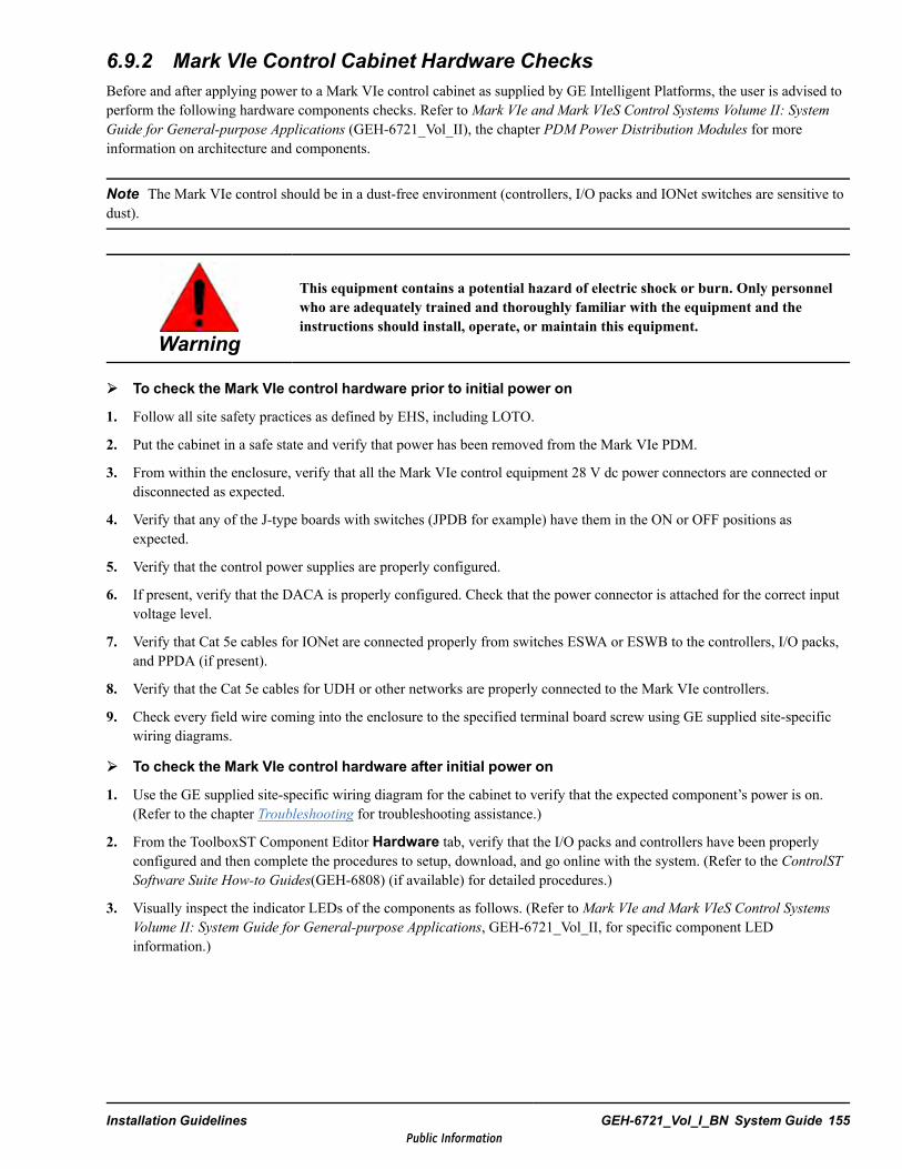
6.9.2 Mark VIe Control Cabinet Hardware ChecksBefore and after applying power to a Mark VIe control cabinet as supplied by GE Intelligent Platforms, the user is advised toperform the following hardware components checks. Refer toMark VIe and Mark VIeS Control Systems Volume II: SystemGuide for General-purpose Applications (GEH-6721_Vol_II), the chapter PDM Power Distribution Modules for moreinformation on architecture and components.
Note The Mark VIe control should be in a dust-free environment (controllers, I/O packs and IONet switches are sensitive todust).
Warning
This equipment contains a potential hazard of electric shock or burn. Only personnelwho are adequately trained and thoroughly familiar with the equipment and theinstructions should install, operate, or maintain this equipment.
To check the Mark VIe control hardware prior to initial power on
1. Follow all site safety practices as defined by EHS, including LOTO.
2. Put the cabinet in a safe state and verify that power has been removed from the Mark VIe PDM.
3. From within the enclosure, verify that all the Mark VIe control equipment 28 V dc power connectors are connected ordisconnected as expected.
4. Verify that any of the J-type boards with switches (JPDB for example) have them in the ON or OFF positions asexpected.
5. Verify that the control power supplies are properly configured.
6. If present, verify that the DACA is properly configured. Check that the power connector is attached for the correct inputvoltage level.
7. Verify that Cat 5e cables for IONet are connected properly from switches ESWA or ESWB to the controllers, I/O packs,and PPDA (if present).
8. Verify that the Cat 5e cables for UDH or other networks are properly connected to the Mark VIe controllers.
9. Check every field wire coming into the enclosure to the specified terminal board screw using GE supplied site-specificwiring diagrams.
To check the Mark VIe control hardware after initial power on
1. Use the GE supplied site-specific wiring diagram for the cabinet to verify that the expected component’s power is on.(Refer to the chapter Troubleshooting for troubleshooting assistance.)
2. From the ToolboxST Component Editor Hardware tab, verify that the I/O packs and controllers have been properlyconfigured and then complete the procedures to setup, download, and go online with the system. (Refer to the ControlSTSoftware Suite How-to Guides(GEH-6808) (if available) for detailed procedures.)
3. Visually inspect the indicator LEDs of the components as follows. (Refer toMark VIe and Mark VIeS Control SystemsVolume II: System Guide for General-purpose Applications, GEH-6721_Vol_II, for specific component LEDinformation.)
Installation Guidelines GEH-6721_Vol_I_BN System Guide 155Public Information
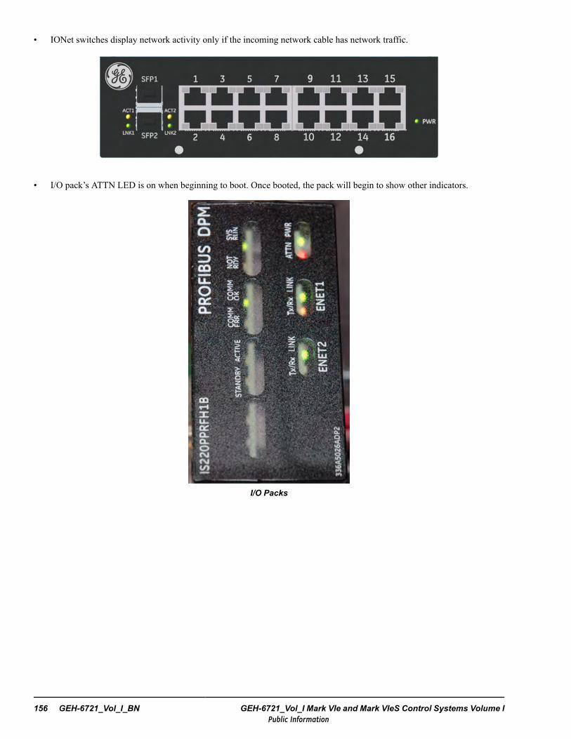
• IONet switches display network activity only if the incoming network cable has network traffic.
• I/O pack’s ATTN LED is on when beginning to boot. Once booted, the pack will begin to show other indicators.
I/O Packs
156 GEH-6721_Vol_I_BN GEH-6721_Vol_I Mark VIe and Mark VIeS Control Systems Volume IPublic Information
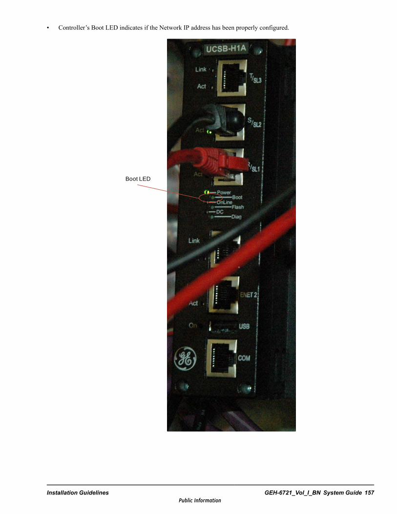
• Controller’s Boot LED indicates if the Network IP address has been properly configured.
Boot LED
Installation Guidelines GEH-6721_Vol_I_BN System Guide 157Public Information
6.10 BPPC-based I/O Pack MigrationAs part of the ongoing support for the Mark VIe and Mark VIeS control platforms, many I/O packs have migrated from aBPPB to a BPPC processor board. This is because the components for BPPB-based processors are end of life, and BPPCprocessors can offer enhanced capabilities. In most instances, the hardware form of the I/O pack that contains the newerBPPC processor ends with an H1B (Mark VIe) or S1B (Mark VIeS).
There are several differences between BPPC-based Mark VIe I/O packs (such as PAICH1B) and Mark VIeS Safety I/O packs(such as YAICS1B) as defined in the following table.
Differences Between BPPC-based Safety and Non-Safety
Mark VIe I/O Packs Mark VIeS Safety Packs
Requires Minimum ControlST V04.04 and the BPPC I/O UpgradeV05.01
Requires ControlST V6.01 or laterSafety packs are not supported in the stand-alone BPPC I/O UpgradePackage. A site outage is required to upgrade to minimum ControlSTV6.01 or later.
Can mix BPPB and BPPC-based I/O packs on the same TMR orDual terminal board (although this is not recommended)
All I/O packs must be the same hardware form on the same terminalboard. It is recommended to purchase adequate BPPC-based spare I/Opacks to have on hand during the migration process.
Auto-reconfiguration can be used for swapping of a BPPB P-Packwith a BPPC P-Pack, once system is equipped (exception forPPRO, PPRA, and PCAA)
Auto-reconfiguration is not supported with Mark VIeS Safety I/O packs
Currently, BPPB-based I/O packs continue to have firmwareupdates and can be upgraded to the latest version
BPPB-based safety packs are not supported in firmware version 5.00 orlater. Firmware versions 5.00 and later are only supporting theBPPC-based safety packs. Do NOT upgrade BPPB-based safety I/Opacks beyond their compatible firmware versions as listed in GEH-6721Volumes II and III.
6.10.1 BPPC-based Mark VIeS Safety I/O PacksBecause the Mark VIeS is applied to safety-critical applications, there are fewer options with respect to migration from BPPBto BPPC based I/O packs. Having fewer options makes it more straight forward to migrate, with less potential conflictsbetween configurations and supported hardware. Safety I/O packs typically have a part number that ends with ‘S1B’. Refer tothe table in the section Mark VIeS Safety I/O Types as a single location for all available safety I/O packs.
Refer to the following guidelines with respect to migration from BPPB to BPPC based Safety Packs:
• It is important to backup the ToolboxST system prior to upgrade.• Reference the above table, Differences Between BPPC-based Safety and Non-Safety.• Reference GEH-6721_Vol_II or GEH-6721_Vol_III (if available) for the section pertaining to the specific I/O pack being
migrated, and the section Compatibility for this I/O pack.• Reference the section Replace Mark VIeS Safety I/O Packs with Upgraded Hardware Form in GEH-6721_Vol_II.• YVIBS1B requires additional steps to be performed in the ToolboxST application. This procedure is available in
GEH-6721_Vol_II.
158 GEH-6721_Vol_I_BN GEH-6721_Vol_I Mark VIe and Mark VIeS Control Systems Volume IPublic Information
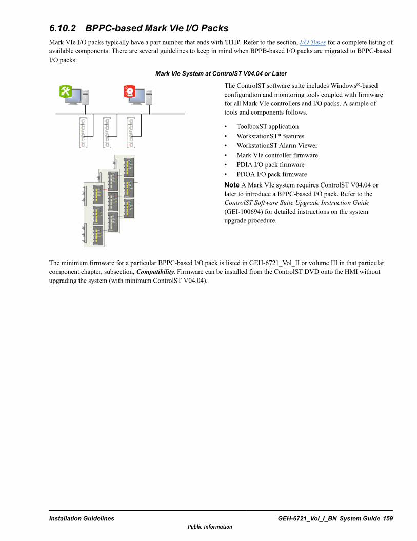
6.10.2 BPPC-based Mark VIe I/O PacksMark VIe I/O packs typically have a part number that ends with 'H1B'. Refer to the section, I/O Types for a complete listing ofavailable components. There are several guidelines to keep in mind when BPPB-based I/O packs are migrated to BPPC-basedI/O packs.
Mark VIe System at ControlST V04.04 or Later
The ControlST software suite includes Windows®-basedconfiguration and monitoring tools coupled with firmwarefor all Mark VIe controllers and I/O packs. A sample oftools and components follows.
• ToolboxST application• WorkstationST* features• WorkstationSTAlarm Viewer• Mark VIe controller firmware• PDIA I/O pack firmware• PDOA I/O pack firmwareNote A Mark VIe system requires ControlST V04.04 orlater to introduce a BPPC-based I/O pack. Refer to theControlST Software Suite Upgrade Instruction Guide(GEI-100694) for detailed instructions on the systemupgrade procedure.
The minimum firmware for a particular BPPC-based I/O pack is listed in GEH-6721_Vol_II or volume III in that particularcomponent chapter, subsection, Compatibility. Firmware can be installed from the ControlST DVD onto the HMI withoutupgrading the system (with minimum ControlST V04.04).
Installation Guidelines GEH-6721_Vol_I_BN System Guide 159Public Information
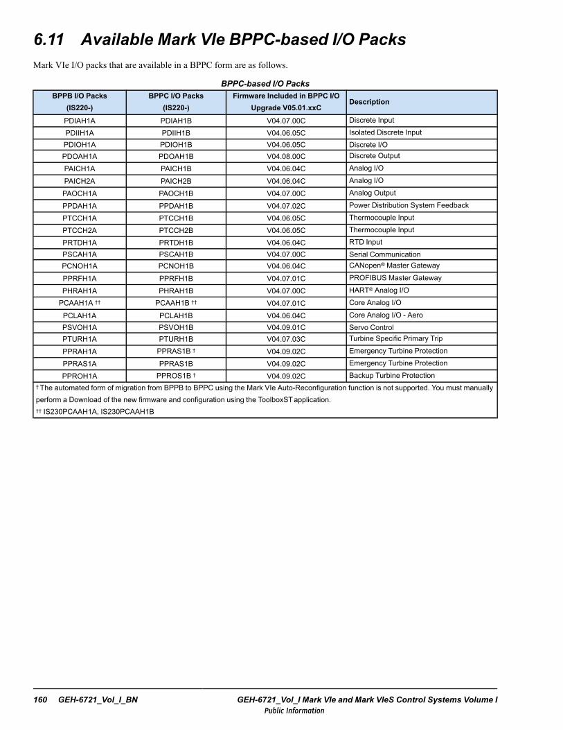
6.11 Available Mark VIe BPPC-based I/O PacksMark VIe I/O packs that are available in a BPPC form are as follows.
BPPC-based I/O PacksBPPB I/O Packs
(IS220-)BPPC I/O Packs
(IS220-)Firmware Included in BPPC I/O
Upgrade V05.01.xxCDescription
PDIAH1A PDIAH1B V04.07.00C Discrete Input
PDIIH1A PDIIH1B V04.06.05C Isolated Discrete InputPDIOH1A PDIOH1B V04.06.05C Discrete I/OPDOAH1A PDOAH1B V04.08.00C Discrete Output
PAICH1A PAICH1B V04.06.04C Analog I/O
PAICH2A PAICH2B V04.06.04C Analog I/O
PAOCH1A PAOCH1B V04.07.00C Analog Output
PPDAH1A PPDAH1B V04.07.02C Power Distribution System Feedback
PTCCH1A PTCCH1B V04.06.05C Thermocouple Input
PTCCH2A PTCCH2B V04.06.05C Thermocouple Input
PRTDH1A PRTDH1B V04.06.04C RTD InputPSCAH1A PSCAH1B V04.07.00C Serial CommunicationPCNOH1A PCNOH1B V04.06.04C CANopen® Master Gateway
PPRFH1A PPRFH1B V04.07.01C PROFIBUS Master Gateway
PHRAH1A PHRAH1B V04.07.00C HART® Analog I/O
PCAAH1A †† PCAAH1B †† V04.07.01C Core Analog I/O
PCLAH1A PCLAH1B V04.06.04C Core Analog I/O - AeroPSVOH1A PSVOH1B V04.09.01C Servo ControlPTURH1A PTURH1B V04.07.03C Turbine Specific Primary Trip
PPRAH1A PPRAS1B † V04.09.02C Emergency Turbine Protection
PPRAS1A PPRAS1B V04.09.02C Emergency Turbine Protection
PPROH1A PPROS1B † V04.09.02C Backup Turbine Protection† The automated form of migration from BPPB to BPPC using the Mark VIe Auto-Reconfiguration function is not supported. You must manuallyperform a Download of the new firmware and configuration using the ToolboxSTapplication.†† IS230PCAAH1A, IS230PCAAH1B
160 GEH-6721_Vol_I_BN GEH-6721_Vol_I Mark VIe and Mark VIeS Control Systems Volume IPublic Information
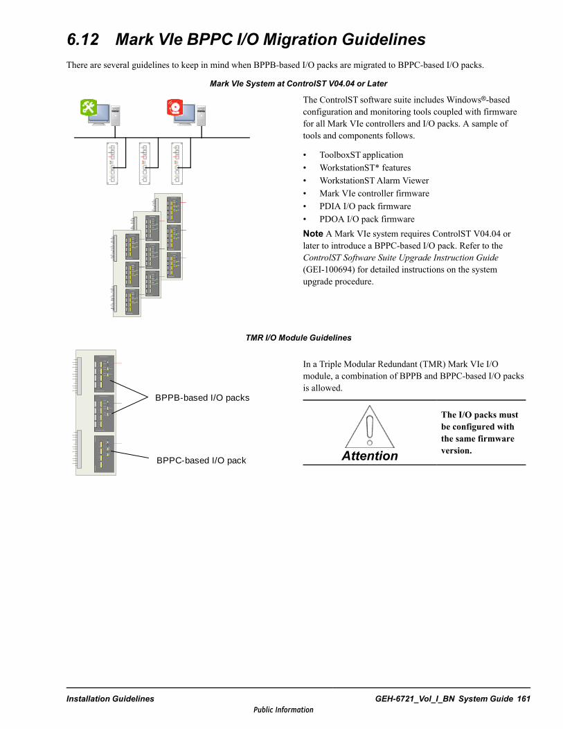
6.12 Mark VIe BPPC I/O Migration GuidelinesThere are several guidelines to keep in mind when BPPB-based I/O packs are migrated to BPPC-based I/O packs.
Mark VIe System at ControlST V04.04 or Later
The ControlST software suite includes Windows®-basedconfiguration and monitoring tools coupled with firmwarefor all Mark VIe controllers and I/O packs. A sample oftools and components follows.
• ToolboxST application• WorkstationST* features• WorkstationSTAlarm Viewer• Mark VIe controller firmware• PDIA I/O pack firmware• PDOA I/O pack firmwareNote A Mark VIe system requires ControlST V04.04 orlater to introduce a BPPC-based I/O pack. Refer to theControlST Software Suite Upgrade Instruction Guide(GEI-100694) for detailed instructions on the systemupgrade procedure.
TMR I/O Module Guidelines
BPPB-based I/O packs
BPPC-based I/O pack
In a Triple Modular Redundant (TMR) Mark VIe I/Omodule, a combination of BPPB and BPPC-based I/O packsis allowed.
Attention
The I/O packs mustbe configured withthe same firmwareversion.
Installation Guidelines GEH-6721_Vol_I_BN System Guide 161Public Information
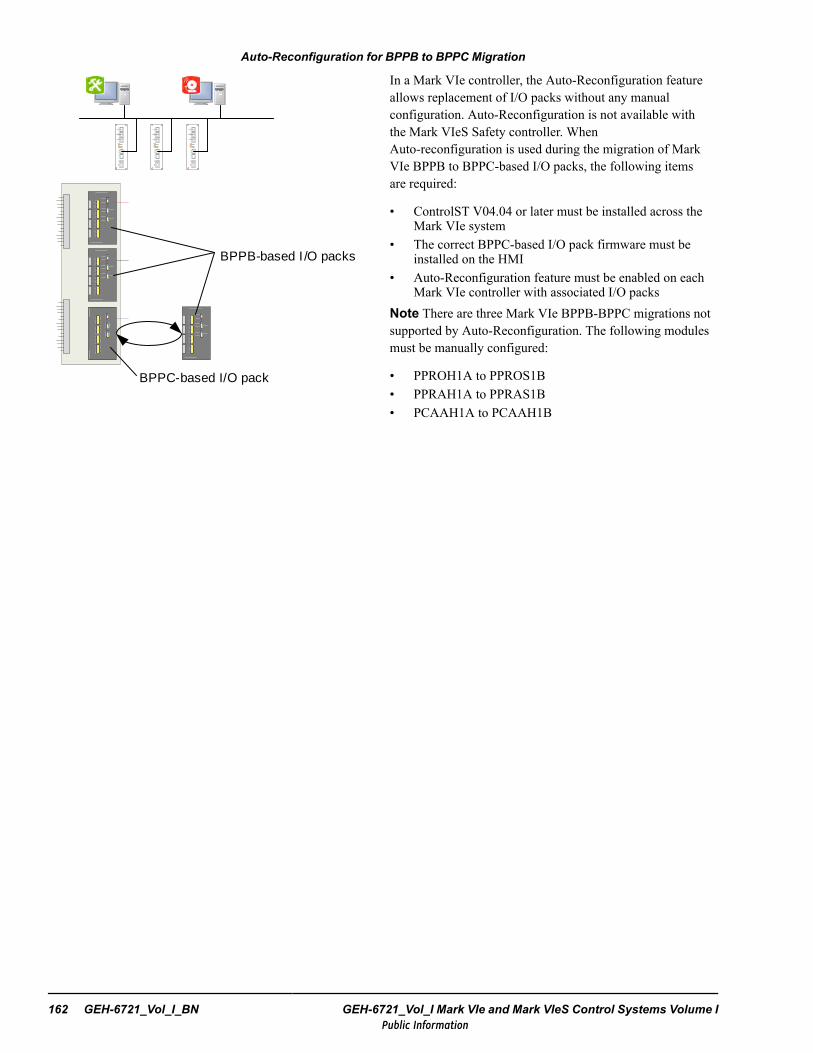
Auto-Reconfiguration for BPPB to BPPC Migration
BPPC-based I/O pack
BPPB-based I /O packs
In a Mark VIe controller, the Auto-Reconfiguration featureallows replacement of I/O packs without any manualconfiguration. Auto-Reconfiguration is not available withthe Mark VIeS Safety controller. WhenAuto-reconfiguration is used during the migration of MarkVIe BPPB to BPPC-based I/O packs, the following itemsare required:
• ControlST V04.04 or later must be installed across theMark VIe system
• The correct BPPC-based I/O pack firmware must beinstalled on the HMI
• Auto-Reconfiguration feature must be enabled on eachMark VIe controller with associated I/O packs
Note There are three Mark VIe BPPB-BPPC migrations notsupported by Auto-Reconfiguration. The following modulesmust be manually configured:
• PPROH1A to PPROS1B• PPRAH1A to PPRAS1B• PCAAH1A to PCAAH1B
162 GEH-6721_Vol_I_BN GEH-6721_Vol_I Mark VIe and Mark VIeS Control Systems Volume IPublic Information
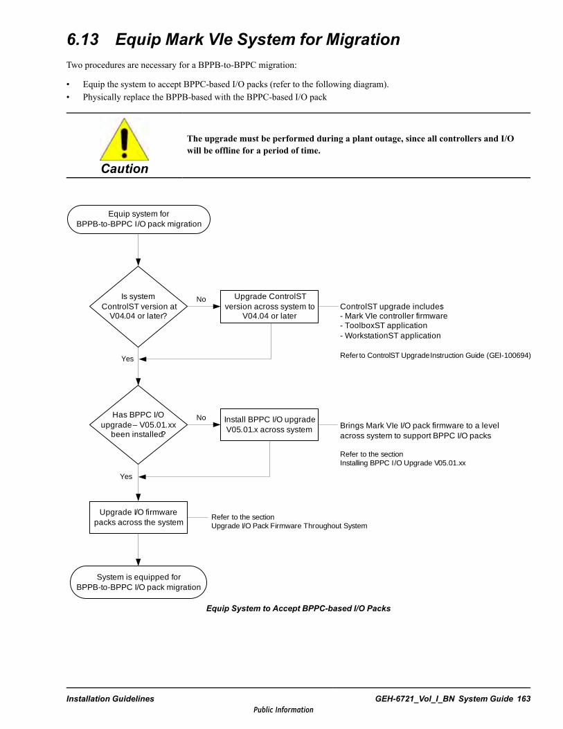
6.13 Equip Mark VIe System for MigrationTwo procedures are necessary for a BPPB-to-BPPC migration:
• Equip the system to accept BPPC-based I/O packs (refer to the following diagram).• Physically replace the BPPB-based with the BPPC-based I/O pack
Caution
The upgrade must be performed during a plant outage, since all controllers and I/Owill be offline for a period of time.
ControlST upgrade includes:- Mark VIe controller firmware- ToolboxST application- WorkstationST application
Refer to ControlST UpgradeInstruction Guide (GEI-100694)
Equip system for BPPB-to-BPPC I/O pack migration
Is system ControlST version at
V04.04 or later?
Upgrade ControlST version across system to
V04.04 or later
Has BPPC I/O upgrade – V05.01.xx
been installed?
Upgrade I/O firmware packs across the system
Install BPPC I/O upgrade V05.01.x across system
Yes
No
No
Yes
Brings Mark VIe I/O pack firmware to a level across system to support BPPC I/O packs
Refer to the sectionInstalling BPPC I/O Upgrade V05.01.xx
System is equipped for BPPB-to-BPPC I/O pack migration
Refer to the section Upgrade I/O Pack Firmware Throughout System
Equip System to Accept BPPC-based I/O Packs
Installation Guidelines GEH-6721_Vol_I_BN System Guide 163Public Information

Notes
164 GEH-6721_Vol_I_BN GEH-6721_Vol_I Mark VIe and Mark VIeS Control Systems Volume IPublic Information
7 Alarm OverviewAlarm management is a vital component to operating and maintaining equipment in power generation or other industrialplants. Reporting of abnormal conditions and trips (with accurate descriptions and high-resolution time tags to identify theorigin) are vital to minimizing mean-time-to-repair (MTTR). The Mark VIe control with the ControlST software suiteprovides solutions for alarm management, prioritization, classification, measurement, and reporting.
7.1 Alarm System ArchitectureEach Mark VIe unit control (such as a turbine control) has its own embedded alarm detection and management system toensure the integrity of its data. Alarm logic is embedded in the overall unit control logic, and runs at the same frame rate,synchronous with the control logic. Therefore, any trip emanating from the control due to a condition such as low lube oilpressure will have a first-out alarm time tag assigned during the same data frame as the trip command. Since trips aresignificant events, they are initiated locally from sensor inputs and internal algorithms. The unit alarm management system isimmune to failures of peripheral networks and supervisory equipment. Should a network malfunction occur, local alarm logic,time tags, and messages are retained in the local controller and are available to operator stations upon restoration of thenetwork.
In normal operation, each unit control communicates its alarm messages and local high-resolution time tags to operatorstations where they are combined into the overall plant alarm management system. The integrity of the time stamps that theoperator sees depends on the system time synchronization, which consists of time coherence and time accuracy. Within a unitcontrol, there is ±1 ms time coherence between time stamps in controllers due to the distributed nature of its I/O. Timesynchronization on the I/O networks is implemented with IEEE-1588 Precision Clock Synchronization Protocol. In addition,there is ±2 ms time coherence between any two units on the control network (UDH), which is implemented with NetworkTime Protocol (NTP).
A time-server is normally provided for plant-wide time synchronization. The server communicates on the control network(UDH) and information network (PDH) with ±1ms accuracy between a plant data point and a time source such as a globalpositioning satellite (GPS). IRIG-B is a commonly used synchronization protocol.
Alarm Overview GEH-6721_Vol_I_BN System Guide 165Public Information
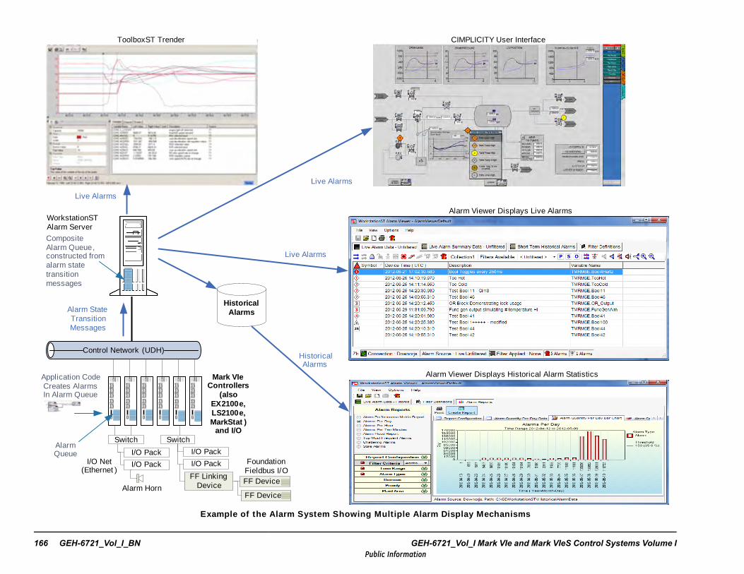
Historical Alarms
Live Alarms
Historical Alarms
WorkstationST Alarm Server
Live Alarms
CIMPLICITY User Interface
Alarm Viewer Displays Live Alarms
Alarm Viewer Displays Historical Alarm StatisticsMark VIe Controllers
(also EX2100e, LS2100e, MarkStat )
and I/O
ToolboxST Trender
Live Alarms
Alarm State Transition Messages
CompositeAlarm Queue, constructed from alarm state transition messages
Alarm Horn
I/O Pack
I/O Pack
FF LinkingDevice
FF Device
I/O Net(Ethernet )
Switch
FF Device
Switch
Foundation Fieldbus I/O
I/O Pack
I/O Pack
Control Network (UDH)
Alarm Queue
Application Code Creates AlarmsIn Alarm Queue
Example of the Alarm System Showing Mult iple Alarm Display Mechanisms
166 GEH-6721_Vol_I_BN GEH-6721_Vol_I Mark VIe and Mark VIeS Control Systems Volume IPublic Information

Plant operators need to prioritize alarms, filter data, lockout nuisance alarms, analyze data, and more effectively apply theavailable data to plant operation. To meet this need, the Mark VIe control with ControlST Toolset is based on ANSI/ISA-18.2,Management of Alarm Systems for the Process Industries to assist in improving the safety, quality, and productivity of thefacility. HMIs running WorkstationST and ToolboxST applications provide a user-friendly environment for visualization,navigation, change management, and analysis of alarm and event conditions with a common, time-coherent data set for theplant.
The comprehensive plant alarm system provided by the ControlST software suite allows operator stations to see alarms fromboth GE controls and third-party components, using OPC to integrate alarm messages and time stamps from third-partyservers with native Mark VIe alarm data. The OPC Alarm and Events (AE) has typically been used for this purpose, but nowwith ControlST V05.03 or later, the newer OPC Unified Architecture (UA) protocol can be used. OPC UA combines thefeatures of OPC DA, AE, and HDAwith the flexibility to include some or all of these features.
An operator needs to be able to see and react to alarms and events from any of the equipment within his jurisdiction. TheWorkstationSTAlarm Server gathers alarms from the controllers or other sources and makes them available to alarm clientssuch as WorkstationSTAlarm Viewer displays. Alarms are also recorded and made available to the WorkstationSTAlarmViewer for historical viewing and statistical analysis. The WorkstationSTAlarm Viewer may run on the same computer as theWorkstationSTAlarm Server or on a separate computer. Refer to GEI-100626, WorkstationSTAlarm Server InstructionGuide.
Alarm Overview GEH-6721_Vol_I_BN System Guide 167Public Information
7.2 Alarm TypesStandards for alarming define five types that occur in the Mark VIe control system as follows:
• Process alarms are created to annunciate abnormal conditions in the plant equipment that the operator needs to beaware of or take action on. The focus of the alarm management system is based on capturing, filtering, visualizing, andanalyzing these process alarm messages. Typically, the word alarm is used to mean a process alarm, since that type ismost commonly used and experienced in the field.
• Hold list alarms advise the operator that an automatic sequence is on hold. Then, the operator can choose to overridethe hold if permitted by the protective logic. Holds are typically used in steam turbine controls. An example hold listalarm is the notification used with controlling the thermal expansion in steam turbines.
• Diagnostic alarms alert the operator to fault conditions in the control equipment (such as a power supply failure) or aninterruption in network communications (issue with cabling or switches).
• Events are important normal occurrences in the operation of a plant such as the closure of the generator breaker.• Sequence of Events (SOE) provide a ±1 ms time stamped message whenever a field contact opens or closes. This
precision is particularly useful in determining the root cause of trips in a power plant that is subject to trips fromelectrical equipment and grid dynamics. To be effective, time synchronized sequence-of-events reporting is neededthroughout the plant. In general, ±1 ms resolution is available on native Mark VIe and Mark VIeS discrete input modulesfor dc contacts and available with less resolution for ac contacts. Time resolution for third-party I/O on fieldbus networksis application-specific.
The maximum number of new alarms that can be processed are as follows:
• A burst load of 400 alarm transitions are supported in a single frame without missing a transition in the internal queue.• A constant load of 100 alarm transitions per second are supported without missing a transition in the internal queue.
7.3 Controller Alarm SubsystemThe Mark VIe and VIeS controllers contain an embedded alarm subsystem that can handle the following data types:
• Boolean Alarms• Analog Alarms (not available with Mark VIeS controller)• Boolean Events• Boolean Holds
Beginning with ControlST V04.04, the following limits to the number of data types are enforced by the ToolboxSTapplication during the build operation of the Mark VIe, EX2100e, and LS2100e controller:
• There can be a maximum of 4096 Boolean Alarms, Analog Alarms, and Holds, but this includes a limit of 512 Holds• Boolean Events are limited to 2048
The state information of each alarm, including the Hold state and the Acknowledged state, is stored in the alarm queue of thecontroller. There are several benefits to having the persistent alarm state information stored in the controller itself rather thanin the HMI:
• If an HMI fails, the alarms are still in the controller. Another HMI can obtain the information from the controller makingall the alarms and their state available for viewing. Neither alarms nor their state are lost.
• Multiple HMIs may be used to view alarms simultaneously since each HMI only needs to get information directly fromthe controller.
• Each alarm has a timestamp of when it became active. If an alarm transitions to inactive and then back to active, the latesttime stamp of when the alarm became active is retained.
• In a redundant controller set, the alarm queue is synchronized so that if one controller fails the other(s) have the alarms.During normal operation, the designated controller sends the alarm states to the HMI and to the other controllers to keepthem in sync. If a controller fails and is replaced, the new controller will initialize its state from the designated controller.Therefore, alarms are not lost if one of the controllers in a redundant set reboots.
168 GEH-6721_Vol_I_BN GEH-6721_Vol_I Mark VIe and Mark VIeS Control Systems Volume IPublic Information
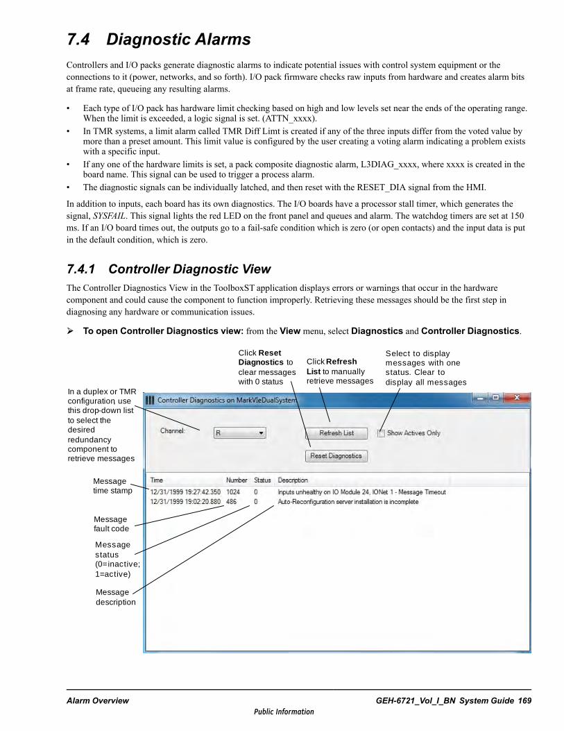
7.4 Diagnostic AlarmsControllers and I/O packs generate diagnostic alarms to indicate potential issues with control system equipment or theconnections to it (power, networks, and so forth). I/O pack firmware checks raw inputs from hardware and creates alarm bitsat frame rate, queueing any resulting alarms.
• Each type of I/O pack has hardware limit checking based on high and low levels set near the ends of the operating range.When the limit is exceeded, a logic signal is set. (ATTN_xxxx).
• In TMR systems, a limit alarm called TMR Diff Limt is created if any of the three inputs differ from the voted value bymore than a preset amount. This limit value is configured by the user creating a voting alarm indicating a problem existswith a specific input.
• If any one of the hardware limits is set, a pack composite diagnostic alarm, L3DIAG_xxxx, where xxxx is created in theboard name. This signal can be used to trigger a process alarm.
• The diagnostic signals can be individually latched, and then reset with the RESET_DIA signal from the HMI.
In addition to inputs, each board has its own diagnostics. The I/O boards have a processor stall timer, which generates thesignal, SYSFAIL. This signal lights the red LED on the front panel and queues and alarm. The watchdog timers are set at 150ms. If an I/O board times out, the outputs go to a fail-safe condition which is zero (or open contacts) and the input data is putin the default condition, which is zero.
7.4.1 Controller Diagnostic ViewThe Controller Diagnostics View in the ToolboxST application displays errors or warnings that occur in the hardwarecomponent and could cause the component to function improperly. Retrieving these messages should be the first step indiagnosing any hardware or communication issues.
To open Controller Diagnostics view: from the View menu, select Diagnostics and Controller Diagnostics.
Click Reset Diagnostics to clear messages with 0 status
Click Refresh List to manually retrieve messages
Select to display messages with one status. Clear to display all messages
In a duplex or TMR configuration, use this drop-down list to select the desired redundancy component to retrieve messages
Message time stamp
Message fault code
Message status (0=inactive; 1=active)
Message description
Alarm Overview GEH-6721_Vol_I_BN System Guide 169Public Information

7.4.2 Diagnostic Alarm ResetThere are three ways to reset a diagnostic alarm:
• from the ToolboxSTApplication (as displayed in the figure on the previous page of the document)• from the Alarm Viewer (right-click the alarm and select Reset) — refer to GEI-100620• using a SYS_OUTPUTS block and the RSTDIAG input pin — refer to GEI-100682
Note Application engineers often program a CIMPLICITYpush button to allow for a diagnostic reset using the RSTDIAGinput pin.
7.4.3 Time StampingThe time stamp applied to an I/O pack diagnostic alarm is the time when that diagnostic originated. When a diagnostic hasbeen reset, a subsequent occurrence of the same diagnostic then creates a new time stamp. If a diagnostic alarm occurs severaltimes without being reset by the operator, it retains the original time stamp.
The WorkstationST* Alarm Viewer Live View displays the diagnostic time when each transition to the active state occurs. If adiagnostic alarm occurs several times, a new time stamp is applied by the WorkstationSTAlarm Server for display in theWorkstationSTAlarm Viewer. However, if the Alarm Server is restarted, or if the connection to the I/O pack's owningcontroller is lost, then the Alarm Server must get an updated dump of the current state of all I/O pack diagnostics from thecontroller. Since the I/O pack only retains the original time when the diagnostic first occurred, the Alarm Server and AlarmViewer would then show the original time after the restart and reconnect. Refer to GEI-100620, WorkstationSTAlarm Viewer.
The ToolboxST application has an I/O Diagnostic Viewer for displaying the I/O pack's current diagnostics alarm status. Itdisplays the I/O pack's known time stamp, which is the time of the first occurrence of the diagnostic. Each time the userrefreshes the viewer, the pack's time stamp is obtained. Refer to GEH-6700, ToolboxST User Guide for Mark VIe Control, thesection, I/O Diagnostic Viewer.
7.4.4 Voter Disagreement Diagnostics Detection (VDDD)Each I/O pack produces diagnostic alarms when it is configured as TMR and any of its inputs disagree with the voted value ofthat input by more than a configured amount. This feature allows the user to find and fix potential problems that wouldotherwise be masked by the redundancy of the control system. The user can view these diagnostics the same way one viewsother diagnostic alarms. The designated controller triggers these diagnostic alarms when an individual input disagrees withthe voted value for a number of consecutive frames. The diagnostic clears when the disagreement clears for a number offrames.
The user configures voter disagreement diagnostics for each variable. Boolean variables are all enabled or disabled by settingthe DiagVoteEnab signal to enable under the configuration section for each input. Analog variables are configured using theTMR_DiffLimit setting under configuration for each point. This difference limit is defined in one of two ways. It isimplemented as a fixed engineering units (EU) value for certain inputs and as a percent of configured span for other variables.For example, if a point is configured as a 4-20 mA input scaled as 0-40 EU, its TMR_DiffLimit is defined as a percent of(40-0). The type of limit checking used is spelled out in the dialog box for the TMR_DiffLimit for each board type. Thefollowing table provides some examples of TMR limit checking.
170 GEH-6721_Vol_I_BN GEH-6721_Vol_I Mark VIe and Mark VIeS Control Systems Volume IPublic Information
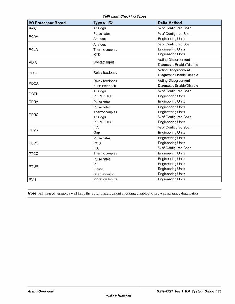
TMR Limit Checking Types
I/O Processor Board Type of I/O Delta MethodPAIC Analogs % of Configured Span
PCAAPulse ratesAnalogs
% of Configured SpanEngineering Units
PCLAAnalogsThermocouplesRTD
% of Configured SpanEngineering UnitsEngineering Units
PDIA Contact InputVoting DisagreementDiagnostic Enable/Disable
PDIO Relay feedbackVoting DisagreementDiagnostic Enable/Disable
PDOARelay feedbackFuse feedback
Voting DisagreementDiagnostic Enable/Disable
PGENAnalogsPT,PT CTCT
% of Configured SpanEngineering Units
PPRA Pulse rates Engineering Units
PPRO
Pulse ratesThermocouplesAnalogsPT,PT CTCT
Engineering UnitsEngineering Units% of Configured SpanEngineering Units
PPYRmAGap
% of Configured SpanEngineering Units
PSVOPulse ratesPOSmA
Engineering UnitsEngineering Units% of Configured Span
PTCC Thermocouples Engineering Units
PTUR
Pulse ratesPTFlameShaft monitor
Engineering UnitsEngineering UnitsEngineering UnitsEngineering Units
PVIB Vibration Inputs Engineering Units
Note All unused variables will have the voter disagreement checking disabled to prevent nuisance diagnostics.
Alarm Overview GEH-6721_Vol_I_BN System Guide 171Public Information
7.5 Process AlarmsProcess alarms are generated by the transition of Boolean or analog variables configured by the ToolboxST application withthe alarm attribute. The variables are driven by sequencing or tied to input points to map values directly from I/O boards.Process alarm variables are scanned during each frame after the sequencing is run. In TMR systems, process alarm variablesare voted and the resulting composite is present in each controller.
Process alarms are time stamped and stored in a local queue in the controller. Changes representing alarms are time stampedand sent to the alarm queue. Reports containing alarm information are assembled and sent over the UDH to the HMIs. Herethe alarms are again queued and prepared for operator display by the alarm viewer.
Operator commands from the HMI, such as alarm Acknowledge, Reset, Lock, and Unlock, are sent back over the UDH to thealarm queue where they change the status of the appropriate alarm. An alarm entry is removed from the controller queuewhen it has returned to normal and has been acknowledged by an operator. The operator or the controller can take actionbased on the process alarms setup.
Process alarms can also be created by having the WorkstationST application scan variables and create alarms. This is usefulwhen alarms need to be created from data coming from third-party equipment.
7.5.1 Process Alarm States and Controller Alarm QueueOnce alarms are generated by the controller (the alarm source), they are placed and maintained in a queue in the controller.The controller maintains the active alarms with controller state (Active, HI, Low, and so forth) and with the command givenfrom the operator (acknowledged, silenced, and so forth). The queue structure holds the alarm state, process value, priority,and shelved, inhibited, silenced, locked, and acknowledged states as well as a timestamp. For a simple Boolean alarm, thecontroller alarm state indicates if the process value is beyond alarm limits. Because analog alarms are configured with moredetailed threshold information, analog alarms also have additional information attached to the alarm state relating to thosethreshold limits, such as if the process value is below the LO threshold or above the HI threshold.
7.5.2 Process Alarm DevelopmentProcess Alarms are typically developed in the Mark VIe controller by using the ToolboxST application. An applicationengineer creates Mark VIe application code in Relay Ladder Diagram (RLD) or Function Block language. Alarms areconfigured using individual variables in the controller. An Alarm Class, defined at a system level, can be created andreferenced by each alarmed variable to control aspects of the alarm such as priority and color indications. Refer to GEH-6808,the section How to Configure Alarm Capability in the ToolboxSTApplication.
Every Boolean variable used in the controller application code has a set of properties including an alarmed property. Anapplication engineer can set the alarmed property of a Boolean variable so that the variable will cause an alarm anytime itsvalue transitions to True. For example, if the application code has a Boolean variable called OVERSPD, the user need onlyset the Alarm property of OVERSPD to cause an alarm to be generated any time OVERSPD transitions to True.
Analog variables such as integers and floating point REAL values can also be configured for alarming. An applicationdesigner can set High, Low, and other threshold limits of an Analog variable (such as an Integer or REAL) so that an alarm isgenerated whenever those thresholds are crossed. This configuration creates child variables in the control logic, and thosevariables can be accessed and modified by application code created by the user. For example, if an integer PRES02 variableexists and the user enables the High threshold limit, a PRES02.H variable is created in application code. The user can writeother application code to change the value of the PRES02.H threshold limit dynamically as the controller is running, and canuse the PRES02.H to drive other control logic. This supports alarm rationalization techniques advocated by ISA 18.2 toreduce the number of false positive alarms.
172 GEH-6721_Vol_I_BN GEH-6721_Vol_I Mark VIe and Mark VIeS Control Systems Volume IPublic Information
The application designer can use as much Relay Ladder or Function Block Diagram logic as is needed to condition theBoolean or Analog variable such that alarms are not triggered unless conditions truly warrant creation of an alarm. Thisability to use arbitrary control logic to condition alarm generation in real-time at fast sample rates is a very powerfulcapability afforded by creating alarms in the controller itself. Alarm detection happens as part of the Mark VIe controllerframe (part of the outputs phase of processing and synchronous to the control logic). Because of this, timestamps of alarmsare very accurate, and can easily be compared to other data collected from the controller since that data is time stamped withexactly the same time as the alarm. Specialized alarm blocks are also available, effectively capturing many design patterns forpre-alarm signal conditioning in a reusable library form.
The alarm system collects exactly what the controller logic detects so there are no losses in resolution and there is noresampling. The Mark VIe controller can run frames as fast as once every 10 milliseconds, and uses POSIX timestamps withnanosecond resolution and sub millisecond accuracy. Comparison of timestamps from alarms that originate from differentcontrollers devices is possible since the controllers and HMIs are all time synchronized with NTP.
When an alarm Boolean first transitions to True, the controller creates a new instance of an alarm record structure and placesit in the alarm queue of the controller. Later, the Boolean might transition to False, but unless the operator takes action, thealarm queue entry remains. If the Boolean again transitions to True, the alarm queue entry is updated. The alarm queue entrywill not be deleted unless the alarm is set for Auto Acknowledge. The operator can acknowledge the alarm, the alarmedBoolean can change to False, and the operator can reset the alarm. The acknowledge and reset may be accomplished in singlekeystroke if the auto-acknowledge feature is enabled.
Events and Holds can be created in a fashion that is very similar to that of process alarms. Sequence of Events (SOEs) arecreated by setting a similar property on an IO Point. Diagnostic Alarms can also be created in the controller by transmissionfrom other subsystems such as from FOUNDATION Fieldbus devices. Diagnostic Alarms are created by firmware itself, not bythe application engineer.
7.5.2.1 Intrinsic Variables and TotalizersIntrinsic variables allow alarm manager commands to be generated when a variable changes state. Totalizers are timers andcounters that store critical data such as number of trips, number of starts, and number of fired hours. The controller provides aspecial block, Totalizer, which maintains up to 64 values in a protected section of non-volatile RAM (NVRAM). ThisTotalizer block should be placed in a protected macro to prevent the logic driving its counters from being modified. Users canset and clear Totalizer counter values from the ToolboxST application. The standard block library instruction guide(GEI-100682) provides more details on using the Totalizer block. Refer to GEH-6700 ToolboxST User Guide for Mark VIeControl, the section, Intrinsic Variables.
7.5.2.2 External Process AlarmsProcess alarms may also enter the alarm system through the WorkstationST application rather than through the Mark VIecontroller. The WorkstationST appliation can scan Boolean variables and create alarms in a manner similar to the Mark VIecontroller. Additionally, the WorkstationST application can import alarms from other systems using OPC AE or OPC UA.
Alarm Overview GEH-6721_Vol_I_BN System Guide 173Public Information

7.6 Alarm Communication FlowOne goal of the alarm system communications infrastructure is to replicate each alarm queue at the point of visualization.Each Mark VIe controller has an alarm queue and each Alarm Viewer must have a copy of those alarm queue entries in orderto display them. The Alarm Viewers get their information from one or more Alarm Servers, which in turn get queue entriesfrom the source of the alarms. Each system has at least one Alarm Server. Many systems have a pair of Alarm Server forredundancy, and these Alarm Servers communicate to synchronize their state machines. The Mark VIe control systems cansupport up to a maximum of 10 supervisory PCs with individual alarm server connections to a unit controller (not includingOSM and Historian if present).
A custom TCP/IP based protocol named SDI is used to transfer alarms from the Mark VIe controller to the Alarm Server.Other custom protocols are used to communicate between the Alarm Server and alarm clients such as the Alarm Viewer. Achange based communication mechanism is used by these protocols, so a client must connect to a server and request an alarmdump to get the current state of all the alarms maintained by the server. Subsequent changes to that state are communicated tothe client by transition messages. If the connection is lost or if there is any question that the client has the correct state, theprocess must be repeated. This is the nature of all change detect protocols, including those used by OPC; the client must firstlearn the current state before change of state notifications are useful.
Configuration information about variables, including alarmed variables, is preloaded into the WorkstationST device by usingthe ToolboxST application, and is updated automatically by a WorkstatonST service that monitors the controller and uploadsconfiguration information. This mechanism provides WorkstationST devices and their clients with metadata like variable datatypes, descriptions, units, display limits, and all of the other attributes of variables and objects that hold variables. Suchmetadata is displayed in the CIMPLICITYand Alarm Viewer screens. Keeping this metadata accurate even as the controllersand other parts of the system are modified is aided by the unidirectional data flow afforded by having the controllers own thevariables and alarms and their generation. Each HMI can have the same view of the alarm information because each HMI getsthe data and metadata from an alarm server which in turn gets the information from the alarm source, typically the Mark VIecontroller. Synchronization issue with alarm state that can be caused by having multiple alarm sources for the same alarm arethereby eliminated.
174 GEH-6721_Vol_I_BN GEH-6721_Vol_I Mark VIe and Mark VIeS Control Systems Volume IPublic Information
8 TroubleshootingThe following sections are provided to aid in common troubleshooting of control system equipment.
8.1 Controller, I/O Pack, IONet Switch Not Powering OnThe following figure provides a decision making flow to aid in troubleshooting power loss to controllers, I/O packs, or IONetswitches.
Warning
Follow all site safety requirements and precautions, including PPE to diagnose theissue while maintaining power to the enclosure.
Troubleshooting GEH-6721_Vol_I_BN System Guide 175Public Information
Controller, IONet switch, or I/O pack power LED is not lit .
Is there voltage at the cable
feeding power to the I/O pack,
Ethernet switch, or controller?
YesReplace the
pack, Ethernet switch, or controller.
Trace the cable back to the
distribution board (for example JPDL,
JPDC, JPDH for packs, also JPDP
for switches).
No
Is there power at the board
connector to the cable?
Yes
No
Is the power distribution board
fed incoming power from another power distribution board?
Yes
Replace the cable between power
distribution board and I/O pack,
Ethernet switch, or controller.
Yes
No
Is there power at the
prior distribution
board output connector?
Are there any blown
fuses?
Replace the fuse.
Yes
No
Does the distribution board have
any switches in the OFF position?
Turn switch to ON.
Yes
No
Is there incoming
power at the input cable?
Yes
No
Is the power distribution board fed
incoming power from a power
supply?
No
Is there input power from the cable leading
to prior distribution
board?
Yes
Replace the power distribution board that is directly connected to the I /O pack, Ethernet switch,
or controller.
No
No
Replace the boardIs there power
at the output connector on
the power supply?
Replace the cable
Is there power at the input to
the power supply?
Yes
Yes
Replace the power supply
Yes
NoContinue to trace power back to cabinet power entry (check circuit breakers, disconnects,
contactors, and so forth).
Replace the power cable that connects
between both power distribution
boards .
Troubleshooting Power Loss to Controllers, I/O Packs, or IONet Switches
176 GEH-6721_Vol_I_BN GEH-6721_Vol_I Mark VIe and Mark VIeS Control Systems Volume IPublic Information
8.1.1 I/O Pack Power LED Not LitI/O Pack Power Troubleshooting
Condition Potential ProblemAll other I/O packs on same terminal board have powerlights lit
I/O pack power connectorI/O pack failure
Some other I/O packs on same terminal board have powerLED lit (or simplex board)
I/O pack power connectorI/O pack failureTerminal board failure
No other I/O packs on same terminal board have powerLEDs lit
Terminal board powerTerminal board failure
Troubleshooting GEH-6721_Vol_I_BN System Guide 177Public Information
8.2 Unable to Download to Controller
Note Before downloading, the controller IP address must be setup. Refer to GEH-6808 for more information.
178 GEH-6721_Vol_I_BN GEH-6721_Vol_I Mark VIe and Mark VIeS Control Systems Volume IPublic Information
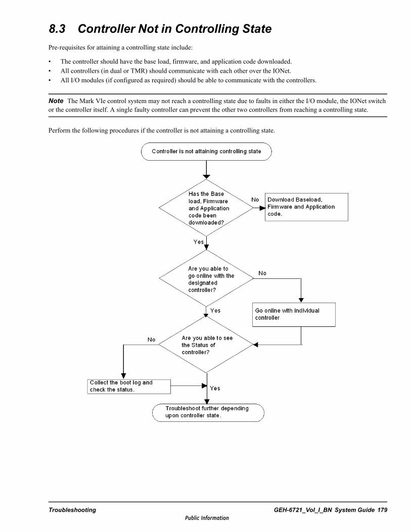
8.3 Controller Not in Controlling StatePre-requisites for attaining a controlling state include:
• The controller should have the base load, firmware, and application code downloaded.• All controllers (in dual or TMR) should communicate with each other over the IONet.• All I/O modules (if configured as required) should be able to communicate with the controllers.
Note The Mark VIe control system may not reach a controlling state due to faults in either the I/O module, the IONet switchor the controller itself. A single faulty controller can prevent the other two controllers from reaching a controlling state.
Perform the following procedures if the controller is not attaining a controlling state.
Troubleshooting GEH-6721_Vol_I_BN System Guide 179Public Information

8.3.1 Controller StatesThe controller states are:
• Power On• d0-MASTER_INITIALIZATION• d1-DC_DETERMINATION• d2-DATA_INITIALIZATION• d3-INPUTS_ENABLED• d5-EXCH_INITIALIZATION• d6-EXCHANGING• d7-SEQUENCING• d8-STANDBY• dA-CONTROLLING
Perform the following procedures if the controller is stalled at Master Installation state.
180 GEH-6721_Vol_I_BN GEH-6721_Vol_I Mark VIe and Mark VIeS Control Systems Volume IPublic Information
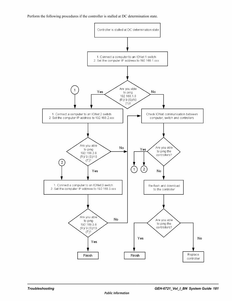
Perform the following procedures if the controller is stalled at DC determination state.
Troubleshooting GEH-6721_Vol_I_BN System Guide 181Public Information
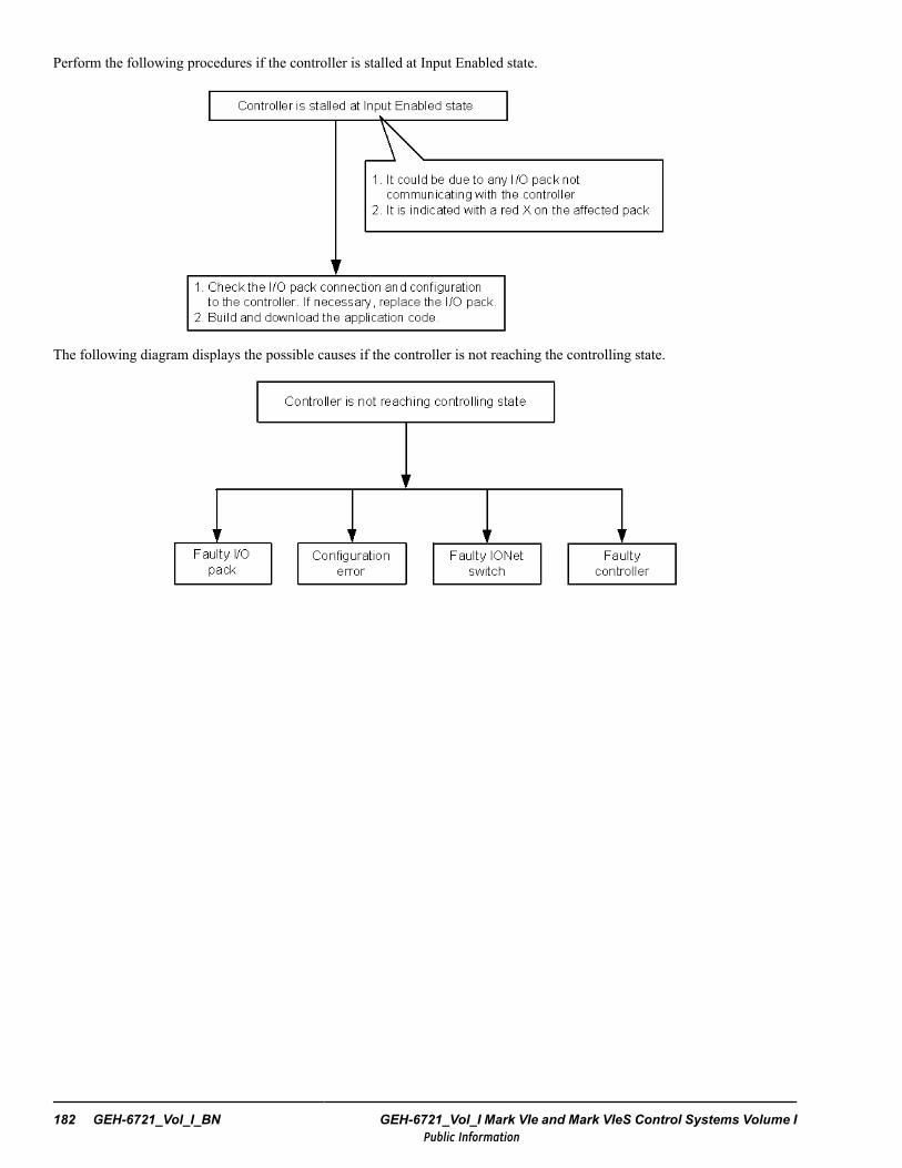
Perform the following procedures if the controller is stalled at Input Enabled state.
The following diagram displays the possible causes if the controller is not reaching the controlling state.
182 GEH-6721_Vol_I_BN GEH-6721_Vol_I Mark VIe and Mark VIeS Control Systems Volume IPublic Information
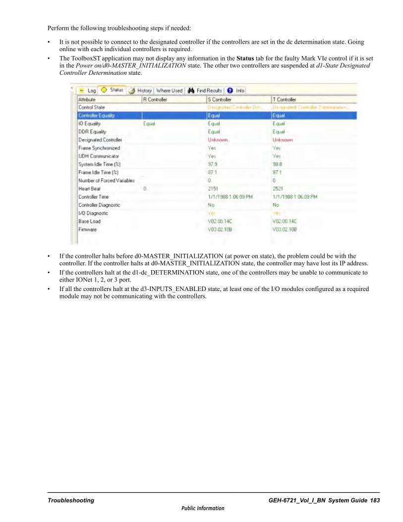
Perform the following troubleshooting steps if needed:
• It is not possible to connect to the designated controller if the controllers are set in the dc determination state. Goingonline with each individual controllers is required.
• The ToolboxST application may not display any information in the Status tab for the faulty Mark VIe control if it is setin the Power on/d0-MASTER_INITIALIZATION state. The other two controllers are suspended at d1-State DesignatedController Determination state.
• If the controller halts before d0-MASTER_INITIALIZATION (at power on state), the problem could be with thecontroller. If the controller halts at d0-MASTER_INITIALIZATION state, the controller may have lost its IP address.
• If the controllers halt at the d1-dc_DETERMINATION state, one of the controllers may be unable to communicate toeither IONet 1, 2, or 3 port.
• If all the controllers halt at the d3-INPUTS_ENABLED state, at least one of the I/O modules configured as a requiredmodule may not be communicating with the controllers.
Troubleshooting GEH-6721_Vol_I_BN System Guide 183Public Information
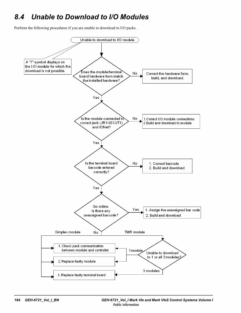
8.4 Unable to Download to I/O ModulesPerform the following procedures if you are unable to download to I/O packs.
184 GEH-6721_Vol_I_BN GEH-6721_Vol_I Mark VIe and Mark VIeS Control Systems Volume IPublic Information

8.5 Unable to Communicate with I/O ModuleIn the ToolboxST application, Component Editor, Hardware tab, a red X symbol on an I/O module indicates that thecontroller is unable to communicate with that I/O module. If multiple modules have red X symbols, the problem may be withthe IONet switch or the I/O module power supply.
To view I/O communication failures between an I/O pack and the controller diagnostic
1. From the ToolboxST application, open the Mark VIe control .tcw file.
2. From the Component Editor, select the Hardware tab and right-click on the I/O pack with a red X.
3. Select View Diagnostics.
Note In TMR I/O modules, the diagnostic displays for the faulty module only.
I/O Pack Communication Troubleshooting
Condition Potential ProblemOther I/O packs on same IONet switch still communicating I/O pack power
Ethernet cable from I/O packIncomplete downloads to pack or controllerImproper ToolboxSTconfigurationBad IONet switch portI/O pack failure
No other I/O packs on same IONet switch are communicating Switch powerSwitch communicationImproper switch configurationSwitch failure
Troubleshooting GEH-6721_Vol_I_BN System Guide 185Public Information
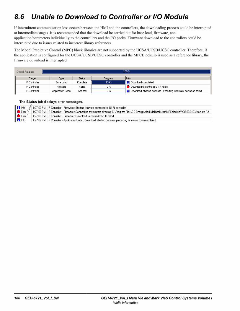
8.6 Unable to Download to Controller or I/O ModuleIf intermittent communication loss occurs between the HMI and the controllers, the downloading process could be interruptedat intermediate stages. It is recommended that the download be carried out for base load, firmware, andapplication/parameters individually to the controllers and the I/O packs. Firmware download to the controllers could beinterrupted due to issues related to incorrect library references.
The Model Predictive Control (MPC) block libraries are not supported by the UCSA/UCSB/UCSC controller. Therefore, ifthe application is configured for the UCSA/UCSB/UCSC controller and the MPCBlockLib is used as a reference library, thefirmware download is interrupted.
186 GEH-6721_Vol_I_BN GEH-6721_Vol_I Mark VIe and Mark VIeS Control Systems Volume IPublic Information
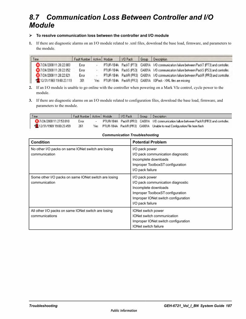
8.7 Communication Loss Between Controller and I/OModule To resolve communication loss between the controller and I/O module
1. If there are diagnostic alarms on an I/O module related to .xml files, download the base load, firmware, and parameters tothe module.
2. If an I/O module is unable to go online with the controller when powering on a Mark VIe control, cycle power to themodule.
3. If there are diagnostic alarms on an I/O module related to configuration files, download the base load, firmware, andparameters to the module.
Communication Troubleshooting
Condition Potential ProblemNo other I/O packs on same IONet switch are losingcommunication
I/O pack powerI/O pack communication diagnosticIncomplete downloadsImproper ToolboxSTconfigurationI/O pack failure
Some other I/O packs on same IONet switch are losingcommunication
I/O pack powerI/O pack communication diagnosticIncomplete downloadsImproper ToolboxSTconfigurationImproper IONet switch configurationI/O pack failure
All other I/O packs on same IONet switch are losingcommunications
IONet switch powerIONet switch communicationImproper IONet switch configurationIONet switch failure
Troubleshooting GEH-6721_Vol_I_BN System Guide 187Public Information
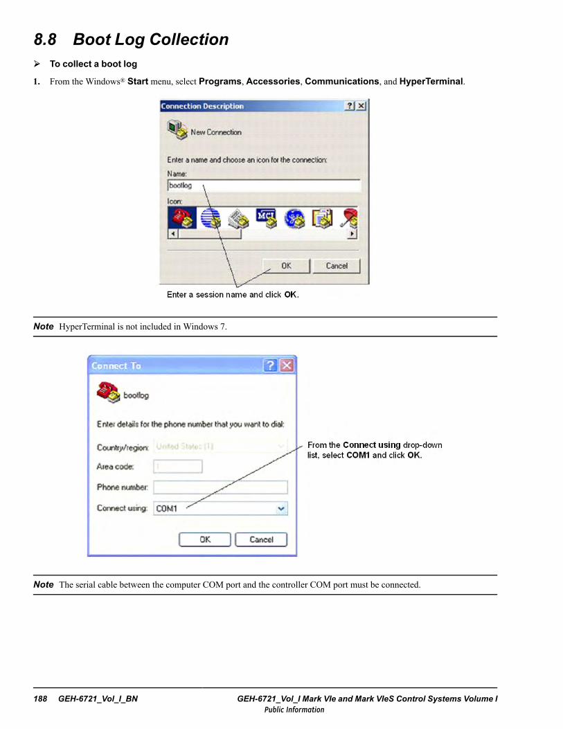
8.8 Boot Log Collection To collect a boot log
1. From the Windows® Start menu, select Programs, Accessories, Communications, and HyperTerminal.
Note HyperTerminal is not included in Windows 7.
Note The serial cable between the computer COM port and the controller COM port must be connected.
188 GEH-6721_Vol_I_BN GEH-6721_Vol_I Mark VIe and Mark VIeS Control Systems Volume IPublic Information
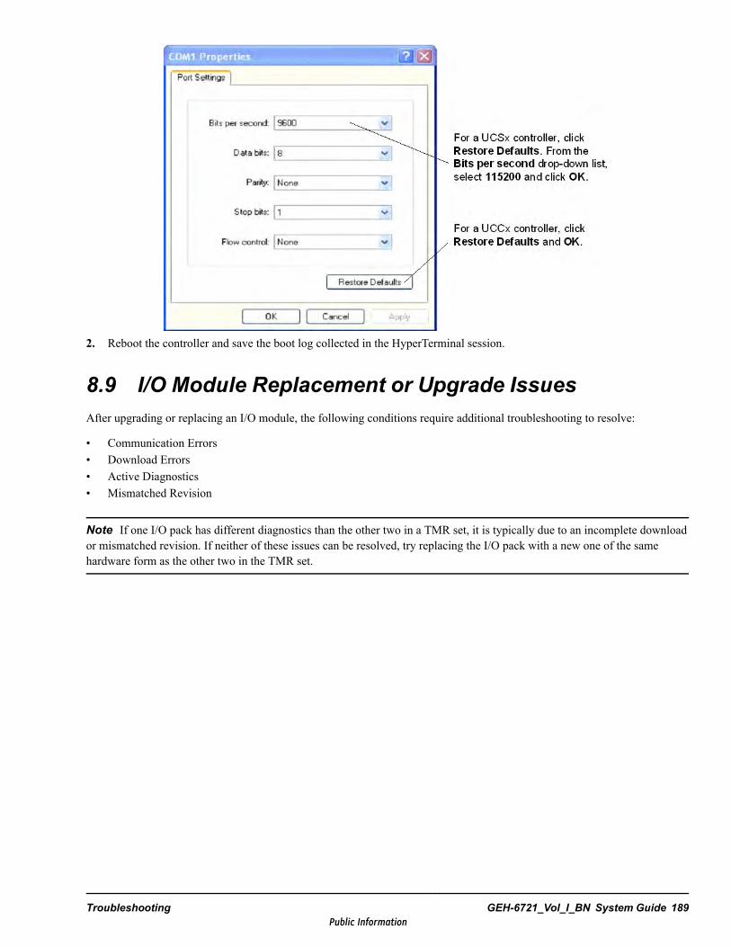
2. Reboot the controller and save the boot log collected in the HyperTerminal session.
8.9 I/O Module Replacement or Upgrade IssuesAfter upgrading or replacing an I/O module, the following conditions require additional troubleshooting to resolve:
• Communication Errors• Download Errors• Active Diagnostics• Mismatched Revision
Note If one I/O pack has different diagnostics than the other two in a TMR set, it is typically due to an incomplete downloador mismatched revision. If neither of these issues can be resolved, try replacing the I/O pack with a new one of the samehardware form as the other two in the TMR set.
Troubleshooting GEH-6721_Vol_I_BN System Guide 189Public Information
8.9.1 Communication ErrorsWhen firmware and application is downloaded to an I/O module, it can take several minutes to install, restart, and re-establishcommunication to the Mark VIe controller. If the ATTN LED is red and flashing at 2 Hz 50%, the IP address has not beenreceived from the controller. For information on ATTN LED flash codes, refer to the Help file for the specific I/O module andthe section Diagnostics.
• Verify that the terminal board bar code configured in the ToolboxST configuration matches the actual hardware.• Verify that the terminal board type, including HW Form, in the ToolboxST configuration matches the terminal board in
the actual I/O module.• Verify that the network cables and switches to the I/O module are plugged in correctly, and that the Link and Activity
LEDs are active.
To view more troubleshooting information: from the Diagnostics tab, select each diagnostic alarm and press F1.
190 GEH-6721_Vol_I_BN GEH-6721_Vol_I Mark VIe and Mark VIeS Control Systems Volume IPublic Information
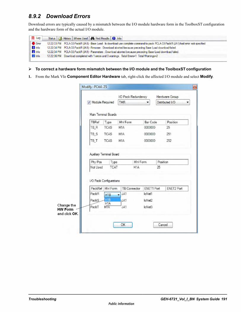
8.9.2 Download ErrorsDownload errors are typically caused by a mismatch between the I/O module hardware form in the ToolboxST configurationand the hardware form of the actual I/O module.
To correct a hardware form mismatch between the I/O module and the ToolboxSTconfiguration
1. From the Mark VIe Component Editor Hardware tab, right-click the affected I/O module and selectModify.
Troubleshooting GEH-6721_Vol_I_BN System Guide 191Public Information
2. From the ToolboxST application, perform a manual Download of the firmware.
Note If the Download is not successful, manually restart the I/O module and perform the Download again.
3. If an I/O module displays during the download, complete the following:
• Check the Component InfoView Log tab for errors. If there is a mismatch between the I/O module configured in theToolboxST application and the actual hardware, the I/O module configuration must be updated to match the hardware.
• If there is still an issue with the download and the hardware configuration has been verified, restart the I/O module, waitone minute, and perform the download again.
• When the download has completed successfully, open the Download wizard and verify that all I/O modules are equal(display green). Check the InfoView log and resolve any Communication Errors.
8.9.3 Active Diagnostics
If the Warning symbol displays on an I/O module:
• I/O module has active diagnostic alarms• Firmware and/or application revisions in the I/O module do not match the ToolboxST configuration
To clear active diagnostics
1. From the Component Editor Hardware tab, select the Diagnostics tab.
2. Select the diagnostic alarm with the red icon and press F1 to display the Help file.
3. Use the possible causes and solutions provided for the specific alarm number to correct the problem.
192 GEH-6721_Vol_I_BN GEH-6721_Vol_I Mark VIe and Mark VIeS Control Systems Volume IPublic Information
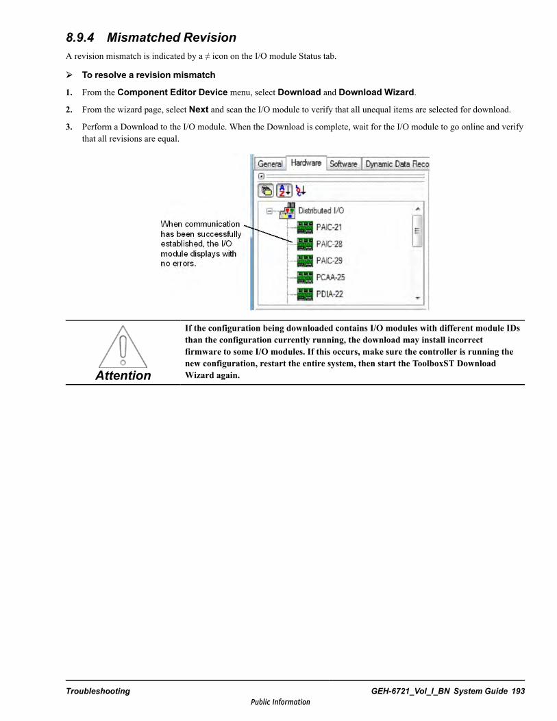
8.9.4 Mismatched RevisionA revision mismatch is indicated by a ≠ icon on the I/O module Status tab.
To resolve a revision mismatch
1. From the Component Editor Device menu, select Download and Download Wizard.
2. From the wizard page, select Next and scan the I/O module to verify that all unequal items are selected for download.
3. Perform a Download to the I/O module. When the Download is complete, wait for the I/O module to go online and verifythat all revisions are equal.
Attention
If the configuration being downloaded contains I/O modules with different module IDsthan the configuration currently running, the download may install incorrectfirmware to some I/O modules. If this occurs, make sure the controller is running thenew configuration, restart the entire system, then start the ToolboxST DownloadWizard again.
Troubleshooting GEH-6721_Vol_I_BN System Guide 193Public Information
8.10 LED IndicatorsController status LED indicators are located on the front panel of the controller. Refer to the LED section for the specificcontroller platform in theMark VIe and Mark VIeS Control Systems Volume II: System Guide for General-purposeApplications (GEH-6721_Vol_II), the chapter Controllers.
The Boot LED is continuously lit during the boot process unless an error is detected. If an error is detected, the LED flashes ata 1-Hz frequency. The LED, when flashing, is on for 500 ms and off for 500 ms. The number of flashes indicates the failedstate. After the flash section, the LED turns off for three seconds. Boot LED flash codes are as follows:
• 1: Failed Serial Presence Detect (SPD) EEPROM• 2: Failed to initialize DRAM or DRAM tests failed• 3: Failed NOR flash file system verification• 4: Failed to load FPGA or PCI failed• 5: CompactFlash device not found• 6: Failed to start IDE driver• 7: CompactFlash image not valid
If the CompactFlash image is valid but the runtime firmware has not been loaded, the Boot LED flashes continuously at a1-Hz frequency. When the firmware is loaded, the Boot LED turns off.
I/O pack and Processor status LEDs are as follows:
• Green LED labeled PWR indicates the presence of control power.• Green LED labeled LINK is provided for each Ethernet port to indicate that a valid Ethernet connection is present.• Yellow LED labeled TxRx is provided for each Ethernet port to indicate when the pack is transmitting or receiving data
over the port.• Red LED labeled ATTN indicates pack status, with the following conditions.
− LED off - no detectable problems with the pack− LED solid on - a critical fault is present that prevents the pack from operating. Critical faults include detected
hardware failures on the processor or acquisition boards, or no application code is loaded.− LED flashing quickly (¼ cycle) - an alarm condition is present in the pack (for example, the wrong pack on the
terminal board), or there is no terminal board, or there were errors loading the application code.− LED flashing at medium speed (¾ cycle) - the I/O pack is not online.− LED flashing slowly (2 cycle) - the I/O pack has received a request to flash the LED indicating that the pack is used
during factory test, or as an aid to confirm the physical location against the ToolboxST application settings.
For further details on BPPx Processor LEDs, refer to the Mark VIe and Mark VIeS Control Systems Volume II: System Guidefor General-purpose Applications (GEH-6721_Vol_II), the Common I/O Module Functionality section BPPx ProcessorLEDs.
194 GEH-6721_Vol_I_BN GEH-6721_Vol_I Mark VIe and Mark VIeS Control Systems Volume IPublic Information
Glossary of Terms
Application code Software that controls the machines or processes, specific to the application.
Balance of Plant (BOP) Plant equipment other than the turbine that needs to be controlled.
Baud A unit of data transmission. Baud rate is the number of bits per second transmitted.
Bit Binary Digit. The smallest unit of memory used to store only one piece of information with two states, such asOne/Zero or On/Off. Data requiring more than two states, such as numerical values 000 to 999, requires multiple bits (seeWord).
Block Instruction blocks contain basic control functions, which are connected together during configuration to form therequired machine or process control. Blocks can perform math computations, sequencing, or continuous control. The toolboxreceives a description of the blocks from the block libraries.
Board Printed wiring board.
Boolean Digital statement that expresses a condition that is either True or False. In the ToolboxST application, it is a datatype for a logical variable.
Broadcast In computer networking broadcast is traffic that is simultaneously addressed to all computers connected to thenetwork.
Bus An electrical path for transmitting and receiving data.
Byte A group of binary digits (bits); a measure of data flow when bytes per second.
CIMPLICITY Operator interface software configurable for a wide variety of control applications.
Configure To select specific options, either by setting the location of hardware jumpers or loading software parametersinto memory.
Control Data Highway (CDH) Redundant Ethernet communication network allows two separate controllers tocommunicate with each other.
Cyclic Redundancy Check (CRC) Detects errors in Ethernet and other transmissions.
Data server A computer that gathers control data from input networks and makes the data available to computers onoutput networks.
Device A configurable component of a process control system.
Distributed Control System (DCS) Control system, usually applied to control of boilers and other process equipment.
Ethernet LAN with a 10/100 M baud collision avoidance/collision detection system used to link one or more computerstogether. Basis for TCP/IP and I/O services layers that conform to the IEEE 802.3 standard, developed by Xerox®, DEC®, andIntel®.
Ethernet Global Data (EGD) Control network and protocol for the controller. Devices share data through EGDexchanges (pages).
EX2100e Excitation Control Latest version of GE generator exciter control; regulates the generator field current tocontrol the generator output voltage.
Fanned input An input to the terminal board that is connected to all three TMR I/O boards.
GEH-6721_Vol_I_BN Glossary of Terms 195Public Information
Firmware The set of executable software that is stored in memory chips that hold their content without electrical power,such as EEPROM.
Flash A non-volatile programmable memory device.
Forcing Setting a live variable to a particular value, regardless of the value blockware or I/O is writing to that variable.
Frame rate Basic scheduling period of the controller encompassing one complete input-compute-output cycle for thecontroller. It is the system-dependent scan rate.
Function The highest level of the blockware hierarchy, and the entity that corresponds to a single .tre file.
Gateway A device that connects two dissimilar LANs or connects a LAN to a wide-area network (WAN), computer, or amainframe. A gateway can perform protocol and bandwidth conversion.
I/O device Input/output hardware device that allows the flow of data.
I/O drivers Interface the controller with input/output devices, such as sensors, solenoid valves, and drives, using a choiceof communication networks.
IONet The Mark VIe I/O Ethernet communication network.
IPAddress The address assigned to a device on an Ethernet communication network.
Logical A statement of a true sense, such as a Boolean.
LS2100e Static Starter control GE’s current state-of-the-art control for static starter control systems, used to bring a gasturbine up to starting speed.
Macro A group of instruction blocks (and other macros) used to perform part of an application program. Macros can besaved and reused.
Modbus A serial communication protocol developed by Modicon for use between PLCs and other computers.
Module A collection of tasks that have a defined scheduling period in the controller.
Multicast The delivery of a message or Information to a group of destination computers simultaneously in a singletransmission from the source.
Online Online mode provides full CPU communications, allowing data to be both read and written. It is the state of thetoolbox when it is communicating with the system for which it holds the configuration. Online is also, a download modewhere the device is not stopped and then restarted.
Period The time between execution scans for a Module or Task. Also a property of a Module that is the base period of allof the Tasks in the Module.
Pin Block, macro, or module parameter that creates a variable used to make interconnections.
Plant Data Highway (PDH) Ethernet communication network between the HMI Servers and the HMI Viewers andworkstations.
Potential Transformer (PT) Measures voltage in a power cable.
Programmable Logic Controller (PLC) Designed for discrete (logic) control of machinery. It also computes math(analog) function and performs regulatory control.
QNX A real time operating system used in the controller.
Relay Ladder Diagram (RLD) A ladder diagram that represents a relay circuit. Power is considered to flow from the leftrail through contacts to the coil connected at the right.
196 GEH-6721_Vol_I Mark VIe and Mark VIeS Control Systems Volume IPublic Information

Sequence of Events (SOE) A high-speed record of contact transitions taken during a plant upset to allow detailedanalysis of the event.
Server A computer that gathers data over the Ethernet from plant devices, and makes the data available to computer-basedoperator interfaces known as viewers.
Simplex Operation that requires only one set of control and I/O, and generally uses only one channel. The entire Mark VIecontrol system can operate in simplex mode.
Simulation Running a system without all of the configured I/O devices by modeling the behavior of the machine and thedevices in software.
Software Implemented Fault Tolerance (SIFT) A technique for voting the three incoming I/O data sets to find andinhibit errors. Note that control also uses output hardware voting.
TCP/IP Communication protocols developed to inter-network dissimilar systems. It is a de facto UNIX standard, but issupported on almost all systems. TCP controls data transfer and IP provides the routing for functions, such as file transfer ande-mail.
ToolboxST AWindows-based software package used to configure the control systems, exciters, and drives.
Trend A time-based plot to show the history of values, similar to a recorder, available with the ControlST Historian and theToolboxST application.
Triple Module Redundancy (TMR) An operation that uses three identical sets of control and I/O (channels R, S, and T)and votes the results.
Unit Data Highway (UDH) Connects the controllers, static starter control system, excitation control system, PLCs, andother GE provided equipment to the HMI Servers.
GEH-6721_Vol_I_BN Glossary of Terms 197Public Information

Notes
198 GEH-6721_Vol_I Mark VIe and Mark VIeS Control Systems Volume IPublic Information
IndexAAcronyms and Abbreviations 5alarmsprocess 172
Applications 13
Ccablefiber-optic 94Instrument 151Routing Guidelines 148Separation and Routing 143shielded 149, 151SMF 94UTP 96
Command Action 54CommunicationLoss 53
Component Sources 96Contaminants 125Control Data Highway (CDH) 89controlleroverview 15
ControlST softwareHistorian 89
DData HighwayPlant 91
DirectiveElectromagnetic Compatibility 119
Disagreement Detector 54Dual Controller 38
EElectrical 119Electromagnetic CompatibilityDirective (EMC) 119
Elevation 125Environment 119Operating 124
EthernetGlobal Data (EGD) 109
FForcing 55Frequency Variations 120
GGrounding 134Notes 139System 135
GuidelinesCableway Spacing 145
HHarmonic Distortion 120Historian 89Human-machine Interface (HMI) 88
II/OPeer 55Wiring 152
Installation 127Support Drawings 134
LLine Variations 120Low Voltage Directive 119
MMedian Value Analog 54MTBF 49
NNEMA 87networklayers 75
PPower Requirements 132Power Sources 36, 132Process Alarms 172ProcessingInput 43Output 47
RRate of Response 56Redundancy Options 37
SSafety Standards 117Simplex Controller 37State Exchange 53Storage 131
GEH-6721_Vol_I_BN Index 199Public Information

Supply Voltage 120
TTerminal Board 17Two Out of Three Logic 54
VVibration 125Voltage Unbalance 120Voting 53
WWire Sizes 150
200 GEH-6721_Vol_I Mark VIe and Mark VIeS Control Systems Volume IPublic Information


Public Information