gem noble liquid calorimeter
TRANSCRIPT


GEM Noble Liquid Calorimeter
Inner Barrel Assembly Concept
April 30, 1993
GEM TN-93- 309
CONTENTS
1.0 INTRODUCTION 2.0 ASSEMBLY CONCEPT SUMMARY
3.0 ASSEMBLY OPERATIONS 3.1 Assemble EM Barrel
3.2 Integrate EM Outer Barrel Structure and EM Barrel Assembly
3.3 Attach Liquid Vessel Head Plates
3.4 Rotate Assembly to Horizontal Position
3.5 Install Inner Hadronic Modules
3.6 Place Liquid and Vacuum Vessel Outer Components on Support Cradles
3.7 Install Liquid Vessel Feedthrough Section
3.8 Install Outer Hadronic Modules
3.9 Install Liquid Vessel Outer Cylinders
3.10 Install Vacuum Vessel Outer Cylinder
3 .1 I Install Vacuum Vessel Inner Cylinder and End Plates
4.0 MAJOR COMPONENT ASSEMBLY DESCRIPTION 4.1 EM Modules
4.2 EM Outer Cylinder Structure Assembly
4.3 Hadron Module Outer Support Washer
4.4 Head Plate Assembly
4.5 Hadron Module
4.6 Liquid Vessel Outer Cylinder
4.7 Liquid Vessel Feedthrough Section
4.8 Liquid Vessel Support Bands
4.9 Vacuum Vessel Outer Cylinder
4.10 Vacuum Vessel End Plate Assembly
4.11 Vacuum Vessel Inner Cylinder Assembly
4.12 Liquid Vessel Cold Mass Support Posts
4.13 Rail Supports
4.14 Feedthroughs
ii
Page
1
4
4
5
6
7
8
9
9
IO
1 I
1 I
12
13
13
13
13
14
15
15
15
16
16
17
18
18
19
19

5.0 ASSEMBLY EQUIPMENT 5.1 EM Module Integration Fixture
5.2 EM Module Lifting Sling
5.3 EM Outer Cylinder Structure Lifting Sling
5.4 EM Outer Cylinder Structure Lifting Sling Kit
5.5 Inner Hadron Module Lifting Sling
5.6 Outer Hadron Module Lifting Sling
5. 7 Hadronic Module Manipulator
5.8 Liquid Vessel Outer Cylinder Support Cradle
5.9 Liquid Vessel Feedthrough Section Support Cradle
5.10 Vacuum Vessel Outer Cylinder Support Cradle
5.11 Vacuum Vessel Outer Cylinder Rail Assembly Fixture
5.12 Vacuum Vessel Outer Cylinder End Rings
5.13 Inner Barrel Calorimeter Support Cradle
5.14 Vacuum Vessel End Plate Assembly Lifting Sling
5.15 Vacuum Vessel Inner Cylinder Assembly Lifting Sling
5.16 Electronic Test Set
Figure 2-1 Inner Barrel Calorimetry Assembly Sequence Functional Flow
2-2 Inner Barrel Assembly Summary
3.1-1 EM Barrel Assembly Process
3.2-1 EM Outer Barrel Structure and Module Assembly Integration
3.3-1 Liquid Vessel Head Plate Attachment
3.4-1 EM Module Assembly Rotation
3.5-1 Inner Hadronic Module Installation
GEM TN-93- 309
20
20
20
21
21
22
22
23
24
24
25
25
26
26
25
26
26
2
3
4
6
7
7
8
3.6-1 Placement of Liquid and Vacuum Vessel Outer Components on Support
Cradles
3.7-1 Liquid Vessel Feedthrough Section Installation
3.8-1 Outer Hadronic Module Installation
3.9-1 Liquid Vessel Outer Cylinder Installation
3.10-1 Vacuum Vessel Outer Cylinder Installation
3.11-1 Vacuum Vessel Inner Cylinder and End Plate Installation
4.2-1 EM Outer Cylinder Structure Assembly
4.3-1 Hadron Module Outer Support Washer
4.4-1 Head Plate Assembly Features
iii
9
JO
11
11
12
12
14
14
15

4.6-1 Features of Liquid Vessel Outer Cylinder
4.7-1 Features of the Liquid Vessel Feedthrough Section
4.8-1 Liquid Vessel Support Bands
4.9-1 Vacuum Vessel Outer Cylinder
4.10-1 Features of the Vacuum Vessel End Plate Assembly
4.11-1 Features of the Vacuum Vessel Inner Cylinder Assembly
4.12-1 Features of the Liquid Vessel Cold Mass Support Posts
4.13-1 Features of the Rail Supports
5.1-1 EM Module Integration Fixture
5.2-1 EM Module Lifting Sling
5.3-1 EM Outer Cylinder Structure Lifting Sling
5.4-1 EM Outer Cylinder Structure Lifting Sling Kit
5.5-1 Inner Hadron Module Lifting Sling
5.6-1 Outer Hadron Module Lifting Sling
5.7-1 Hadronic Module Manipulator
5.9-1 Liquid Vessel Outer Cylinder Support Cradle
5.11-1 Vacuum Vessel Outer Cylinder Rail Assembly Fixture
5.13-1 Preparation of Calorimeter Support Cradle for Load Transfer
5.14-1 Vacuum Vessel End Plate Assembly Lifting Sling
5.15-1 Vacuum Vessel Inner Cylinder Assembly Lifting Sling
iv
GEM TN ·- 93 - 309
15
16
16
17
17
18
19
19
20 21
21
22
22
23
23
24
25
27 27 28

GEM TN-93-309
1.0 INTRODUCTION The Inner Barrel Calorimetry will be assembled in the North Assembly Building at the
IR-5 Site. Major components of each subassembly will be fabricated at off site locations, shipped
to the SSCL, and integrated during the assembly process. Upon arrival at the IR-5 Site,
components will be inspected, tested, and stored in the North Assembly Building until required
in the assembly process. Arrival of these components will be scheduled to minimize the need for
storage space. Components to be fabricated and assembled at offsite locations were chosen to
facilitate assembly and minimize the need for specialized fabrication equipment at the SSCL.
Onsite assembly was considered to be the most practical for the Barrel Calorimetry because of
associated transportation and handling difficulties. The mass of the fully assembled Inner Barrel
will be approximately 465 Mg and the radius and length of this cylindrical mass will be 2.82 m
and 3.94 m, respectively.
2.0 ASSEMBLY CONCEPT SUMMARY The Inner Barrel includes 13 different major components (Section 4.0) which are
integrated in a series of I 1 assembly operations. The functional sequence associated with the
assembly process is identified in Figure 2-1 and a pictorial representation of these steps is shown
in Figure 2-2.
The assembly procedure starts with the stacking of the Electromagnetic (EM) Modules on
two halves of an assembly fixture which are then closed, forming the EM Barrel Assembly with
the strip lines folded to the inside (Fig. 2-2a). The EM outer cylinder structure (Fig. 2-2b),
containing the central washer, is then placed over the EM modules (Fig. 2-2c) and bolted to the
support tabs on the outer circumference of the EM modules to form the EM Module Assembly.
After placing the strip lines in the notches in the upper flange of the barrel structure
assembly, one head plate of the liquid vessel (including half the liquid vessel inner cylinder) is
then positioned on the assembly and bolted to the flange on the barrel structure assembly (Fig. 2-
2d). This plate is then used to lift the assembly and place it over the second half of the liquid
vessel inner cylinder which has been prepositioned with the other head plate on a rotation fixture
(Fig. 2-2e). The strip lines are again placed in notches provided in the flange attaching the EM
outer barrel structure to the head plates. After bolting the second liquid vessel head plate, the
two halves of the liquid vessel inner cylinder are welded and the assembly is rotated to the
horizontal position in .preparation for placement of the Hadronic Modules.
I
GEM TN-93-309
1.0 Assemble EM 2.0 Integrate EM
4.0 Rotate Outer Barrel 3.0 Attach Liquid
Barrel .. Structure & EM • Vessel Head Plates • Assembly to
Barrel Assembly Horizontal Position
5.0 Install Inner 6.0 Place Liquid & 7. O Install Liquid 8.0 Install Outer
Hadronic Modules • Vacuum Vessel .. Vessel ..... Hadronic Modules Outer Components Feed-Through on Support Cradle Section
. 9.0 Install Liquid 10.0 Install 11.0 Install Vacuum
Vessel Outer Vacuum Vessel Vessel Inner
Cylinders Outer Cylinder Cyl & End Plates
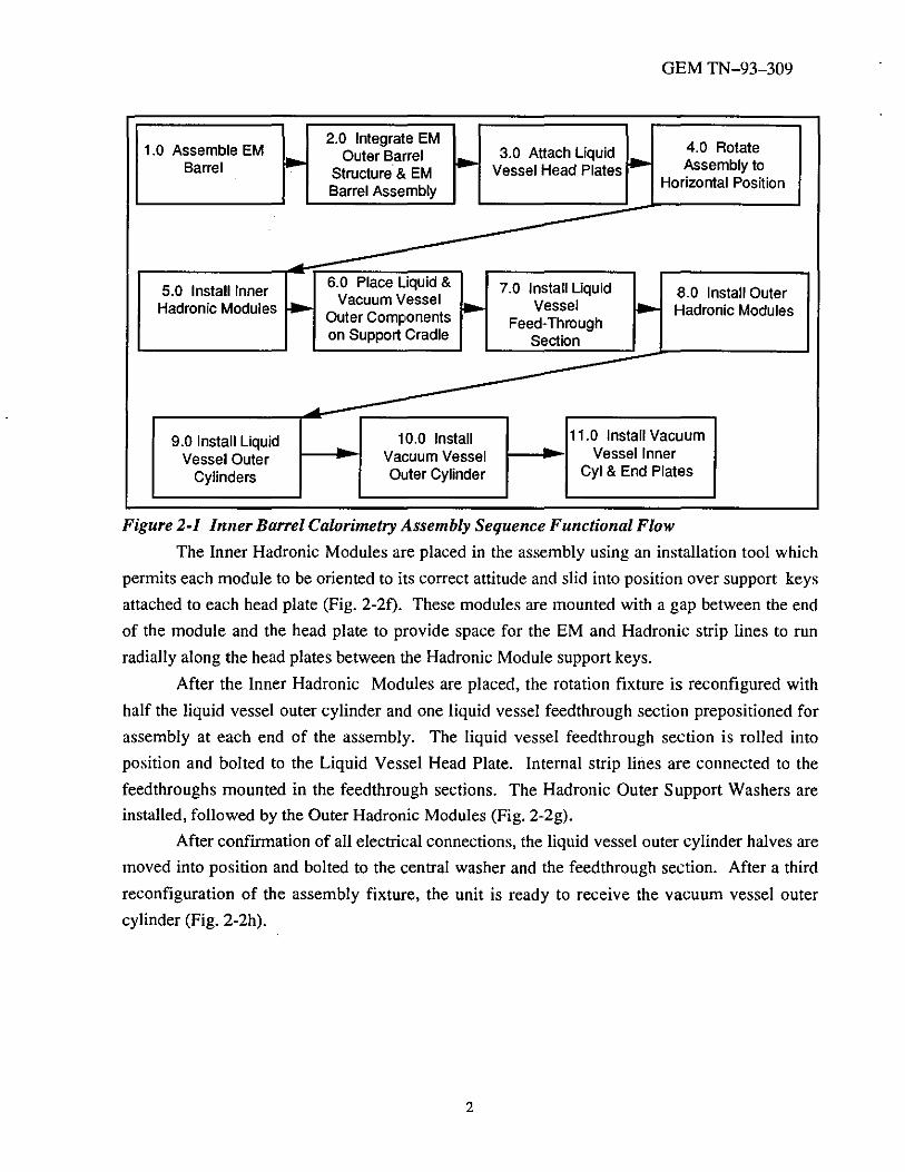
Figure 2-1 Inner Barrel Calorimetry Assembly Sequence Functional Flow
The Inner Hadronic Modules are placed in the assembly using an installation tool which
permits each module to be oriented to its correct attitude and slid into position over support keys
attached to each head plate (Fig. 2-2f). These modules are mounted with a gap between the end
of the module and the head plate to provide space for the EM and Hadronic strip lines to run
radially along the head plates between the Hadronic Module support keys.
After the Inner Hadronic Modules are placed, the rotation fixture is reconfigured with
half the liquid vessel outer cylinder and one liquid vessel feedthrough section prepositioned for
assembly at each end of the assembly. The liquid vessel feedthrough section is rolled into
position and bolted to the Liquid Vessel Head Plate. Internal strip lines are connected to the
feedthroughs mounted in the feedthrough sections. The Hadronic Outer Support Washers are
installed, followed by the Outer Hadronic Modules (Fig. 2-2g).
After confirmation of all electrical connections, the liquid vessel outer cylinder halves are
moved into position and bolted to the central washer and the feedthrough section. After a third
reconfiguration of the assembly fixture, the unit is ready to receive the vacuum vessel outer
cylinder (Fig. 2-2h).
2

r: -,---------~ ,.... _______ ...... _______ __., .- -------- ~
I .-"------------~ •. - ll-. r------.--;-,-.. ~ 'r -•;~ ... ,' , 'a~ I' '"'~ '~' ,' I N ~
., ..... I·~ I ., ..... ,~
~ - - - - - - mw - a~ -- -- - - ----~ 't-
3
s
GEM TN-93-309
. / r - ~ ~ r ~ ~ r /,
~ ~ ')o
~ ~ •
-~ .. --: { ,..,, r"' L
_,..• ;,.•11' I ~ ~ ~ H I L
, .... \'\ II I ~~ II' II , II I ".Ill ·- - ! _>._\,11_1 _ _ r:
:----.------------~
I f' - - - - - _ .. _ - -
\
; ... 11
" " I ~ lj
JI ~ IJ
~ c
GEM TN-93-309
The vacuum vessel outer cyinder, mounted on a support cradle for installation of end
rings which preclude out-of-roundness and support for the cylinder on the rail assembly fixture,
is placed on the rail assembly fixture using the overhead crane. The cylinder is rolled into
position and the cold mass support posts are attached to the liquid vessels support bands. These
support posts provide the load path into the liquid vessel and provide thermal isolation. Rail
supports are slid into positions which lock to the vacuum vessel outer cylinder. The Inner Barrel
Support Cradle is then rolled into position to accept the full load of the Calorimeter. The
Support Cradle provides height adjustments and roll transfer capability for installation into the
scintillating barrel in the Experiment Hall. Rails on the Support Cradle are raised and brought
into contact with the rollers on the rail support, causing the support cradle to accept the entire
load of the assembly.
The rotation fixture is then removed (Fig. 2-2i) to permit attachment of the vacuum vessel
end plates, feedthrough sections, and inner barrel. These major components are moved into close
proximity to the assembly to permit the strip lines to be strung through the ports and the
feedthroughs to be attached to the vacuum vessel. The Inner Barrel Calorimetry assembly is
completed with the bolting of the vacuum vessel feedthrough sections to the outer cylinder and
the welding of the vacuum vessel inner barrel to the end plates (Fig. 2-2j).
3.0 ASSEMBLY OPERATIONS 3.1 Assemble EM Barrel
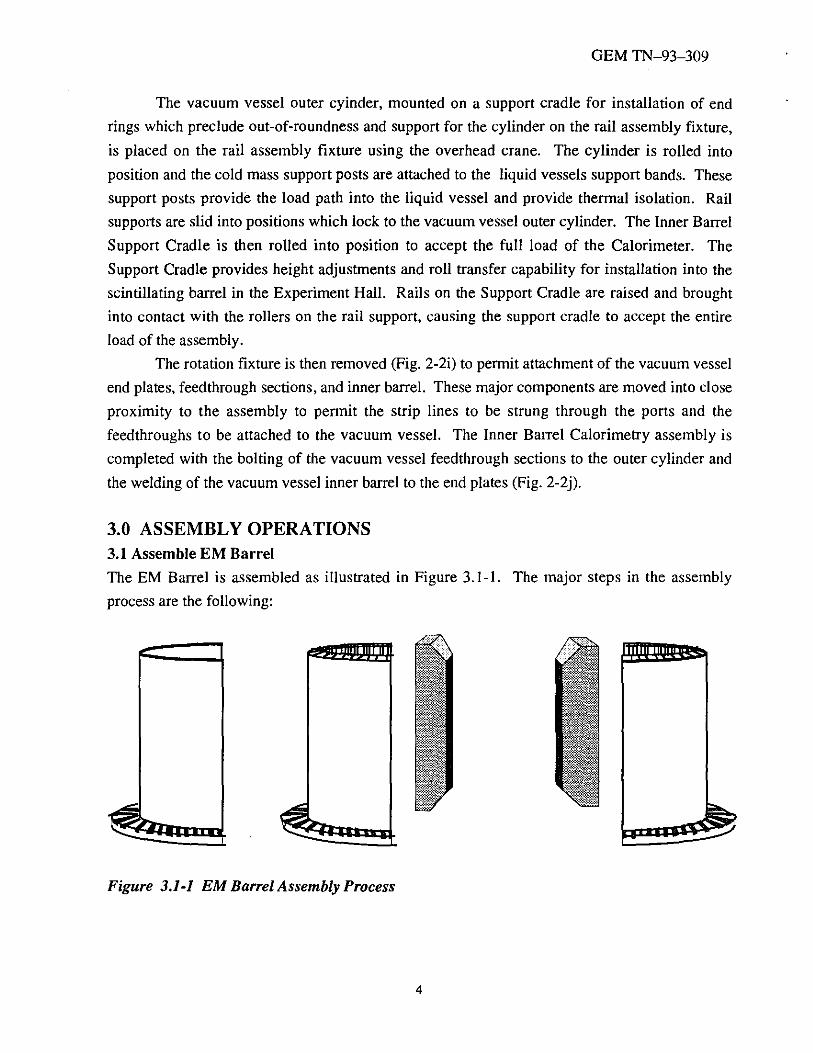
The EM Barrel is assembled as illustrated in Figure 3.1-1. The major steps in the assembly
process are the following:
Figure 3.1-1 EM Barrel Assembly Process
4
GEM TN-93-309
1.0 Fully assembled modules are lifted with the overhead crane and the EM module
lifting sling, placed in the assembly fixture, and temporarily attached to the vertical stabilizers.
2.0 Strip lines are placed in notches in the lower plate of the assembly fixture and run to
the outside of the assembly.
3.0 Each module is electrically tested.
4.0 The remaining modules are progressively placed on the fixture using a similar
process.
5.0 After all 20 modules have been placed in each half of the fixture, all modules are
electrically tested in preparation for closure of the two fixture halves.
6.0 Assembly fixture halves are moved to the closed position.
7.0 The seventeen tensioning straps on the inner radius of the EM cylinder are attached
and lightly tensioned to stabilize the assembly.
8.0 Strip lines at the top of the assembly are folded to the inside and temporarily attached
in preparation for removal of the assembly fixture vertical stabilizers.
9.0 The overhead crane is attached to the assembly fixture vertical stabilizer, bolts
attaching the vertical fixture to the base plate are removed, and the vertical stabilizer is lifted
away from the assembly with the overhead crane.
10.0 The second half of the vertical stabilizer is removed following the same procedure.
11.0 The seventeen external tensioning straps are installed and internal and external
straps are tensioned to the desired load.
12.0 The EM barrel assembly is now ready for integration with the barrel structure
assembly.
3.2 Integrate EM Outer Barrel Structure and EM Barrel Assembly
The EM Outer Barrel Structure is integrated with the EM Barrel Assembly as illustrated in
Figure 3.2-1. The major steps in the integration process are the following:
1.0 Using the EM Barrel Outer Barrel Structure lifting sling, the Barrel Structure Assembly is
lifted with the overhead crane and slid down over the EM Module Assembly.
2.0 The Structure Assembly and the EM Module Assembly are attached with bolts
through the Structure Assembly into the support/axial restraints located on the outside of each
EM module. Additional temporary bolts are also added to support lifting operations during the
Liquid Vessel Head Plate attachment.
3.0 Strip lines are unfolded from the center and placed in the outer barrel flange notches.
4.0 Each EM Module is electrically tested.
5.0 The upper end of the assembly is now ready for head plate installation.
5

GEM TN-93-309
Figure 3.2-1 EM Outer Barrel Structure and Module Assembly Integration
3.3 Attach Liquid Vessel Head Plates
Attachment of the Head Plates to the assembly is illustrated in Figure 3.3-1. The major steps in
the attachment process are the following:
1.0 One Head Plate Assembly is lifted using the overhead crane and the EM Outer Barrel
Structure Lifting Sling and positioned on the EM Barrel Assembly.
2.0 The Head Plate is bolted to the flange on the outer barrel.
3.0 One end plate of the rotation fixture is lifted with the overhead crane, placed upon
the the Head Plate, and bolted to the Head Plate.
4.0 Lower strip lines are positioned in the notches in the outer barrel flange and secured
in preparation for movement of the entire assembly.
5.0 The second Head Plate Assembly is lifted using the overhead crane and the modified
EM Outer Barrel Structure Lifting Sling Kit and placed upon the other end plate of the rotation
fixture which is attached to the rotation support
6.0 The second Head Plate is bolted to the end plate of the rotation fixture.
7 .0 The overhead crane is attached to the end plate of the rotation fixture which is
attached to the EM Module Assembly and the entire assembly is lifted and placed upon the other
rotation fixture end plate which is attached to the rotation support.
8.0 All modules are electrically checked.
6

GEM TN-Q3-309
9 .0 The upper rotation fixture end plate is removed to provide access to the liquid vessel
inner barrel which must be welded in the center.
10.0 All modules are electrically checked.
11.0 The upper rotation fixture end plate is reattached to the liquid vessel head plate in
preparation for rotation.
•\ / " ~
" ~ ' ~ ' • " ~
' '
_I 'I, '
3.4 Rotate Assembly to Horizontal Position
Rotation of the EM Module Assembly to the horizontal position is illustrated in Figure 3.4-1.
The major steps in the rotation process are the following:
1.0 The overhead crane hook is attached to the upper rotation fixture end plate.
2.0 The load is transferred to the overhead crane by using the jack stands to move the
center of gravity of the assembly out of the vertical plane.
3.0 After the load has been transferred to the overhead crane, the jack stands are removed
and the assembly is lowered to the horizontal position where it rests on the support cradle.
4.0 All modules are electrically checked.
7

Figure 3.4-1 EM Module Assembly Rotation
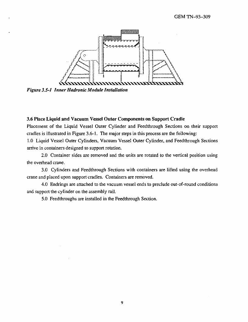
3.5 Install Inner Hadronic Modules
GEM TN-93-309
Installation of the Inner Hadronic Modules is illustrated in Figure 3.5-1. The major steps
in the installation process are the following:
1.0 Work platforms are installed to provide access to the top of the assembly where the
Module installation begins.
2.0 Load carrying aluminum bars (Module Supports) are bolted to the inside of each
head plate and both sides of the central structural washer using predrilled and tapped holes.
3.0 The EM strip lines are placed between the Module Supports which have sufficient
thickness to preclude strip line binding and chaffing.
4.0 Hadronic Modules are lifted and placed in the assembly with the Module
Manipulator.
5.0 The modules are attached to the load strips with a retention block that slides through
a rectangular hole in the module end plate and the load strip.
6.0 Strip lines from the Hadronic Modules follow the same path as those for the EM
Modules, therefore running to one or both sides of the center of each module.
7 .0 After one module has been placed, a second is placed to complete the row at the top
of the assembly and both are electrically checked.
8.0 Tubular stays are inserted through holes in the head plate located circumferentially at
the center of each inner module and radially between the inner and outer modules. The tubes are
welded flush to the head plates.
9.0 Subsequent modules are attached using the same procedure, proceeding from top to
bottom of the assembly. The work platform height is reduced as the work proceeds downward.
I 0.0 An electrical check of all EM and Hadronic Modules is performed.
8
GEM TN-93-309
3.6 Place Liquid and Vacuum Vessel Outer Components on Support Cradle
Placement of the Liquid Vessel Outer Cylinder and Feedthrough Sections on their support
cradles is illustrated in Figure 3.6-1. The major steps in this process are the following:
1.0 Liquid Vessel Outer Cylinders, Vacuum Vessel Outer Cylinder, and Feedthrough Sections
arrive in containers designed to support rotation.
2.0 Container sides are removed and the units are rotated to the vertical position using
the overhead crane.
3.0 Cylinders and Feedthrough Sections with containers are lifted using the overhead
crane and placed upon support cradles. Containers are removed.
4.0 Endrings are attached to the vacuum vessel ends to preclude out-of-round conditions
and support the cylinder on the assembly rail.
5.0 Feedthroughs are installed in the Feedthrough Section.
9

GEM TN-93-309
, \
'::i o _...._ ........ ...._....._...._ .............................. , ... ,
Figure 3.6-1 Placement of Liquid and Vacuum Vessel Outer Components on Support Cradles
3.7 Install Liquid Vessel Feedthrough Sections
Liquid Vessel Feedthrough Section installation is illustrated in Figure 3.7-1. The major steps in
the process are the following:
1.0 Floor jacks are used to temporarily support one side of the assembly and the load is
removed from the support cradle.
2.0 Support cradle and rotation fixture end are removed.
3.0 The end of the rotation fixture is extended.
4.0 One feedthrough section and one half of the Liquid Vessel Outer Cylinder are
prepositioned for installation.
5.0 The rotation fixture support cradle is repositioned and the floor jack is removed.
6.0 Steps 1.0 through 5.0 are repeated for the opposite end of the assembly.
II
Figure 3.7-1 Liquid Vessel Feedthrough Section Installation
7 .0 The Feedthrough Sections are mated to the assembly and bolted in place with seal
welds covering the bolts.
8.0 Floor jacks are reinstalled.
IO

GEM TN-93-309
9.0 The internal strip lines are connected to the feedthroughs, including the strip lines for
the Outer Hadronic Modules which are connected to the Modules after their installation.
3.8 Install Outer Hadronic Modules
Installation of the Outer Hadronic Modules is illustrated in Figure 3.8-1. The major steps in the
installation process are the following:
1.0 Work platforms are reinstalled to provide access to the top of the assembly where the
Outer Module installation begins.
2.0 The Hadronic Outer Support Washers are installed in two halves.
3.0 Load carrying aluminum bars (Module Supports) are bolted to the inside of the Outer
Support Washers and both sides of the Central Structural Washer, using predrilled and tapped
holes. These load strips are placed radially outward and centered between the module supports
for the Inner Hadronic Modules, precluding projective cracks between Hadronic Modules.
4.0 Hadronic Modules are lifted and placed in the assembly with the Module
Manipulator.
5.0 The modules are attached to the load bars with a retention block that slides through a
rectangular hole in the module end plate and the load bar.
6.0 Strip lines, already connected to the Feedthroughs, are attached to the mother boards
on the Hadronic Modules and the module is electrically checked.
7.0 Subsequent modules are attached using the same procedure, proceeding from top to
bottom of the assembly. The work platform height is reduced as the work proceeds downward.
8.0 After the last Hadronic Module is installed, all modules are electrically checked.
Figure 3.8-1 Outer Hadronic Module Installation
3.9 Install Liquid Vessel Outer Cylinders
Installation of the Liquid Vessel Outer Cylinders is illustrated in Figure 3.9-1. The major steps
in the installation process are the following:
1.0 The prepositioned halves of the Liquid Vessel Outer Cylinder are rolled into position
and bolted to the Central Washer and the Feedthrough Section with seal welds covering the bolts.
11

GEM TN-93-309
2.0 The liquid vessel is then pressure checked under both positive and negative gauge
pressure conditions.
3.0 Multi-layer Insulation is installed on the exterior of the Outer Cylinder.
Note: After further study the Liquid Vessels may be installed following a procedure similar to
that planned for the Vacuum Vessel Outer Cylinder which was selected on the basis of the
vessel's complexity.
Figure 3.9-1 Liquid Vessel Outer Cylinder Installation
3.10 Install Vacuum Vessel Outer Cylinder
Installation of the Vacuum Vessel Outer Cylinder is illustrated in Figure 3.10-1. The major steps
in the installation process are the following:
1.0 The Vacuum Vessel Outer Cylinder is prepositioned on the assembly rails using the
overhead crane and the floor supports are moved following a procedure similar to that used in
prepositioning the Liquid Vessel Outer Cylinder halves.
vessel.
2.0 Liquid vessel support bands are temporarily attached to the exterior of the liquid
,I ~ ;1 ;1 ;1 ;I .................... ,, ..... ~ ......... I -
.. I I
Figure 3.10-1 Vacuum Vessel Outer Cylinder Installation
3.0 The Vacuum Vessel Outer Cylinder is then rolled along the assembly rails into the
proper horizontal position to permit attachment of the cold mass support posts to the liquid vessel
support bands.
4.0 Temporary attachment of liquid vessel support bands to liquid vessel is removed.
5.0 Support stanchions are placed and bottom supports are welded to the vacuum vessel.
6.0 Rail supports are slid into position and bolted to the vacuum vessel outer cylinder.
12
GEM TN-93-309
7 .0 The Inner Barrel Calorimeter support cradle, after being rolled into position under the
Calorimeter, is raised to accept the full load of the assembly through the cold mass support posts.
8.0 All assembly fixtures are removed.
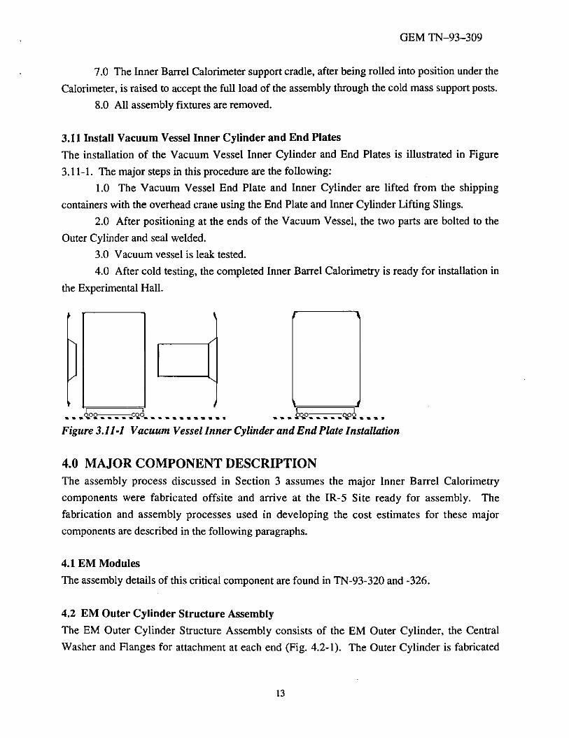
3.11 Install Vacuum Vessel Inner Cylinder and End Plates
The installation of the Vacuum Vessel Inner Cylinder and End Plates is illustrated in Figure
3.11-1. The major steps in this procedure are the following:
1.0 The Vacuum Vessel End Plate and Inner Cylinder are lifted from the shipping
containers with the overhead crane using the End Plate and Inner Cylinder Lifting Slings.
2.0 After positioning at the ends of the Vacuum Vessel, the two parts are bolted to the
Outer Cylinder and seal welded.
3.0 Vacuum vessel is leak tested.
4.0 After cold testing, the completed Inner Barrel Calorimetry is ready for installation in
the Experimental Hall.
........ ho .............. G..O~ ......... Figure 3.11-1 Vacuum Vessel Inner Cylinder and End Plate Installation
4.0 MAJOR COMPONENT DESCRIPTION The assembly process discussed in Section 3 assumes the major Inner Barrel Calorimetry
components were fabricated offsite and arrive at the IR-5 Site ready for assembly. The
fabrication and assembly processes used in developing the cost estimates for these major
components are described in the following paragraphs.
4.1 EM Modules
The assembly details of this critical component are found in TN-93-320 and -326.
4.2 EM Outer Cylinder Structure Assembly
The EM Outer Cylinder Structure Assembly consists of the EM Outer Cylinder, the Central
Washer and Flanges for attachment at each end (Fig. 4.2-1 ). The Outer Cylinder is fabricated
13

GEM TN-93-309
from 4' x 10' x 0.5'' sheet stock. Sheets are cut to length, rolled to radius, cut to arc length, bevel
ground, welded and finish ground, rolled as a complete cylinder to round and machined to
roundness and wall thickness. The Central Washer is fabricated from 4 sheets of 7' x 7' x 1.25"
plate stock, which are each to form quarter sections of the large washer. The radial ends are
bevel welded together. OD and ID edges are machined, making the large washer which
corresponds to the dimensions of the EM Outer Cylinder (ID) and the Liquid Vessel Outer
Cylinder (OD). The Flanges are made from 2" x 2.25" x 96" bar stock, rolled to radius, cut to arc
length, welded at the ends, machined to finished dimensions, machined recesses for strip lines,
and drilled and counterbored. The Central Washer and the Flanges are bevel welded to the Outer
EM Cylinder. All surfaces are prepared prior to welding and are cleaned following welding.
4.3 Hadron Module Outer Support Washer
The Outer Support Washer is depicted in Figure 4.3-1. The plate is fabricated from 4 each sheet
stock of 0.75" Aluminum. The ID and OD are waterjet cut into each quarter section and
additional machining is necessary on the ends to ensure a square weld joint. The seams are
prepared by bevel grinding, then welded and finish ground. A final machine pass is required to
bring the part to ID, OD and wall thickness. After the part is welded and cleaned, it is drilled and
tapped to allow for attachment of the Hadronic Sections.
EM Outer Cylinder Central Washer
Flang~
I ~
~
Structure Assembly
Figure 4.2-1 EM Outer Cylinder Structure Assembly
14

GEM TN-93-309
Threaded Mounting Hole
Support Keyway
Typical Hadronic Module
Figure 4.3-1 Hadron Module Outer Support Washer
4.4 Head Plate Assembly
The Head Plate Assembly is comprised of a Head Plate, Conical Adapter and a Cryostat Inner
Cylinder (Fig. 4.4-1). The Head Plate is fabricated from 4 each, 6' x 6' sheets of 0.75"
Aluminum. The ID and OD are waterjet cut into each quarter section and additional machining
is necessary on the ends to ensure a square weld joint. The seams are prepared by bevel
grinding, then welded and finish ground. A final machine pass is required to bring the part to ID,
OD and wall thickness. The Conical Adapter is fabricated in_ the same way using 2 each, 3' x 6' x
0.75" Al sheet, including one additional step to roll form the sections to a conic profile. The
Cryostat Inner Cylinder is also fabricated in the same way using 2 each, 4' x 8' x 0. 75" Al sheet,
including one additional step to roll form the sections to a cylindrical profile. The mating
surfaces of all pieces are ground and prepared for weld assembly. After the joint is welded and
cleaned, the Head Plate is drilled and tapped to allow for attachment of the Hadronic Sections.
Head Plate
Conical Adapter
Cryostat Inner Cylinder
Figure 4.4-1 Head Plate Assembly Features
4.5 Hadron Module
The assembly of this critical component is described in TN-93-311.
15

GEM TN-93-309
4.6 Liquid Vessel Outer Cylinder
The Liquid Vessel Outer Cylinder is fabricated from 12 sheets of 4' x 10' x 0.5'' stock Aluminum.
The basic structure of these vessel shell halves is illustrated in Figure 4.6-1. The sheet stock is
cut to axial length, rolled to radius, cut to radial length, bevel ground, welded and cleaned, rolled
as a cylinder to assure roundness, machined to obtain OD and wall thickness and loaded
vertically to a container that would support breakover, for shipment.
Liquid Vessel Outer Cylinder Halves
'·-· ~ Assembly Rollers
Figure 4.6-1 Features of Liquid Vessel Outer Cylinder
4.7 Liquid Vessel Feedthrough Section
The components and features of the Liquid Vessel Feed through Section are illustrated in Figure
4. 7-1. The Feed through Sections are fabricated from 4 each, Aluminum sheet stock. The ID and
OD are waterjet cut into each quarter section, the sections are roll formed to a conic profile and
additional machining is necessary on the ends to ensure a square weld joint. The seams are
prepared by bevel grinding, then welded and finish ground. A final machine pass is required to
bring the part to ID, OD and wall thickness. After the joint is welded and cleaned, the
Feedthrough Section is machined to create the feedthrough ports, mounting flange, stripline
connections and drilled and tapped holes.
Mounting Flange
Feedthrough Structure
Feedthrough Port
Figure 4.7-1 Features of the Liquid Vessel Feedthrough Section
4.8 Liquid Vessel Support Band
16

GEM TN-93-309
The Support Bands are fabricated from 2" x 2.25" x 96" Stainless Steel bar stock, rolled to
radius, cut to arc length, notched at the ends, machined to finished dimensions, and drilled and
counterbored.
Liquid Vessel Outer Cylinder
Top of Support Post
Support Band
Figure 4.8-1 Liquid Vessel Support Bands
4.9 Vacuum Vessel Outer Cylinder
The Vacuum Vessel Outer Cylinder is fabricated from 12 sheets of 4' x 10' x 0.5" stock
Aluminum. The basic structure of this vessel shell is illustrated in Figure 4.9-1. The sheet stock
is cut to axial length, rolled to radius, cut to radial length, bevel ground, welded and cleaned,
rolled as a cylinder to assure round, machined to obtain OD and wall thickness and loaded
vertically to a container that would support breakover, for shipment.
v- Vessel Outer Cylinder ,
6oo~cod "--- Assembly Cradle
Figure 4.9-1 Vacuum Vessel Outer Cylinder
17

GEM TN-93-309
4.10 Vacuum Vessel End Plate Assembly
The End Plate Assembly is comprised of a Feedthrough Section, End Plate and Conical Adapter.
These pieces are depicted in Figure 4.10-1. The Feed through Section is fabricated from 2 each,
stock sheets of 0.75" Aluminum. The ID and OD are waterjet cut into each quarter section and
additional machining is necessary on the ends to ensure a square weld joint. The seams are
prepared by bevel grinding, then welded and finish ground. A final machine pass is required to
bring the part to ID, OD and wall thickness. The End Plate is created from 4 sheets of 0.5''
Aluminum sheet stock, cut, ground, welded, cleaned, finish machined and prepared for further
assembly. The Conical Adapter is fabricated in the same way using 2 each, 3' x 6' x 0.75" Al
sheet, including one additional step to roll form the sections to a conic profile. The mating
surfaces of all pieces are ground and prepared for weld assembly. After the joint is welded and
cleaned, the Feedthrough Section is machined for 40 feedthrough ports.
Feedthrough Section
End Plate
Conical Adapter
Figure 4.10-1 Features of the Vacuum Vessel End Plate Assembly
18
GEM TN-93-309
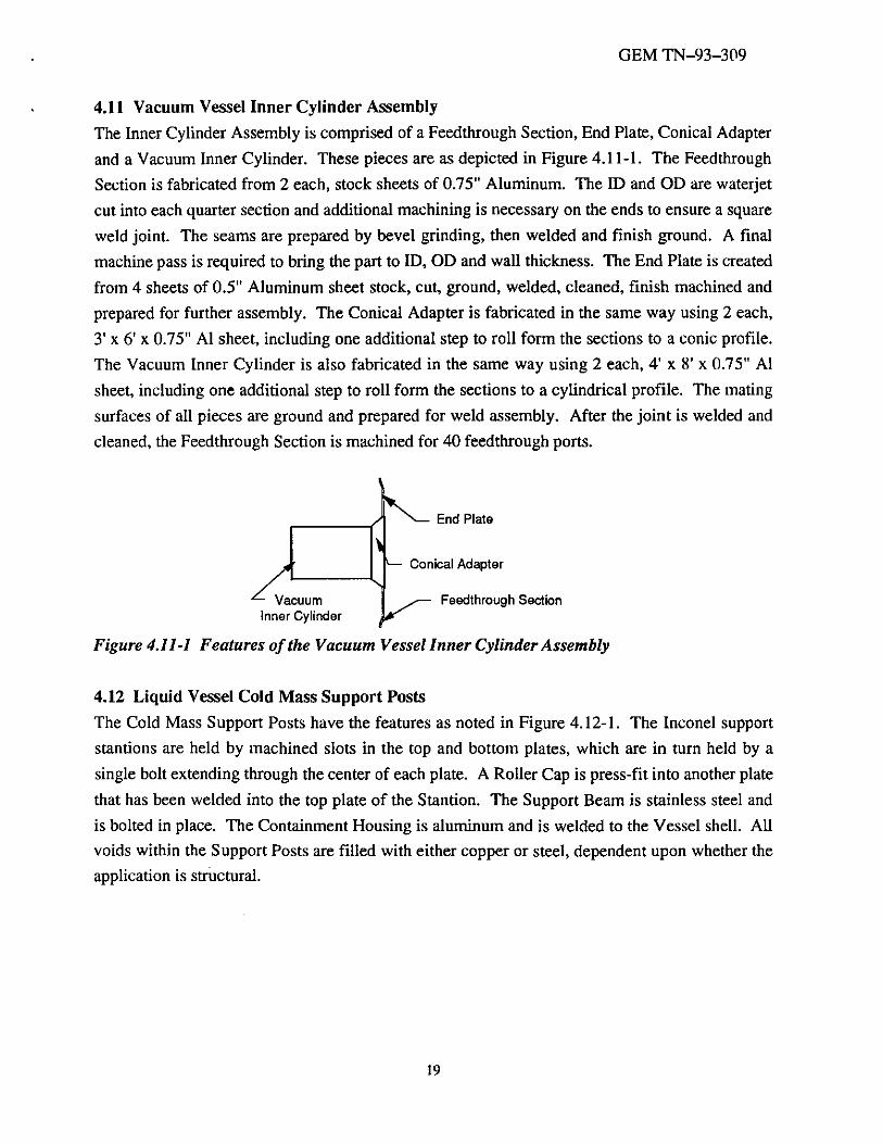
4.11 Vacuum Vessel Inner Cylinder Assembly
The Inner Cylinder Assembly is comprised of a Feedthrough Section, End Plate, Conical Adapter
and a Vacuum Inner Cylinder. These pieces are as depicted in Figure 4.11-1. The Feedthrough
Section is fabricated from 2 each, stock sheets of 0.75" Aluminum. The ID and OD are waterjet
cut into each quarter section and additional machining is necessary on the ends to ensure a square
weld joint. The seams are prepared by bevel grinding, then welded and finish ground. A final
machine pass is required to bring the part to ID, OD and wall thickness. The End Plate is created
from 4 sheets of 0.5'' Aluminum sheet stock, cut, ground, welded, cleaned, finish machined and
prepared for further assembly. The Conical Adapter is fabricated in the same way using 2 each,
3' x 6' x 0.75" Al sheet, including one additional step to roll form the sections to a conic profile.
The Vacuum Inner Cylinder is also fabricated in the same way using 2 each, 4' x 8' x 0.75" Al
sheet, including one additional step to roll form the sections to a cylindrical profile. The mating
surfaces of all pieces are ground and prepared for weld assembly. After the joint is welded and
cleaned, the Feedthrough Section is machined for 40 feedthrough ports.
End Plate
Conical Adapter
Vacuum Inner Cylinder
Feedthrough Section
Figure 4.11-1 Features of the Vacuum Vessel Inner Cylinder Assembly
4.12 Liquid Vessel Cold Mass Support Posts
The Cold Mass Support Posts have the features as noted in Figure 4.12-1. The Inconel support
stantions are held by machined slots in the top and bottom plates, which are in turn held by a
single bolt extending through the center of each plate. A Roller Cap is press-fit into another plate
that has been welded into the top plate of the Stantion. The Support Beam is stainless steel and
is bolted in place. The Containment Housing is aluminum and is welded to the Vessel shell. All
voids within the Support Posts are filled with either copper or steel, dependent upon whether the
application is structural.
19

GEM TN-93-309
------ Roller Cap
----- Central Bolt
lnconel Support Stantion
Containment Housing
Support Beam
Figure 4.12-1 Features of the Liquid Vessel Cold Mass Support Posts
4.13 Rail Supports The Rail Supports are weld assembled from the components shown in Figure 4.13-1, a Stainless
Steel Support Structure, SS Push/Pull Clevis, and Hilman Rollers. All surfaces to be welded are
cleaned and bevel ground. After welding all surfaces are ground smooth.
Push/Pull Clevis
Hilman Rollers w/ Hydraulic Actuators
Figure 4.13-1 Features of the Rail Supports
20

GEM TN-93-309
4.14 Feedthroughs
The assembly of this critical component is described in TN-93-315.
5.0 ASSEMBLY EQUIPMENT Fixtures and handling equipment will be required during the assembly process to assure proper
assembly and preclude endangering calorimeter components and personnel. This equipment
ranges from simple to complex and the engineering development likewise will vary from little to
extensive. The function of each item of equipment is identified in this section and the key
features are illustated in conceptual drawings.
5.1 EM Module Integration Fixture
The EM Module integration fixture (Fig. 5.1-1) is designed to hold and stablilze the EM Modules
as they are assembled into two 1t segments and to facilitate the closure of these segements into
the 2p configuration. Particular attention is paid to the protection of mother boards and strip lines. The fixture is designed for easy removal after the tensioning straps on the 2it configuration
are attached and the assembly unit is stable.
Figure 5.1-1 EM Module Integration Fixture
5.2 EM Module Lifting Sling
The EM Module lifting sling (Fig. 5.2-1) attaches to each end of the EM Modules to permit
lifting of the complete module. These lifting slings, combined with a strong back and overhead
21

GEM TN-93-309
crane, can be used to place the completed module in the cold tank for test, insertion and removal
from the shipping container, and stacking modules into the EM Module integration fixture.
Figure 5.2-1 EM Module Lifting Sling
5.3 EM Outer Cylinder Structure Lifting Sling
This piece of equipment (Fig. 5.3-1) is designed to permit lifting of the EM outer cylinder
structure and the EM barrel assembly using the overhead crane. Bolt patterns matching those on ·
the cylinder structure and the barrel assembly are provided in the lifting sling.
0
Outer holes to match Head Plate
• • Inner holes to match attachment flange on Outer EM Structure Assembly
Figure 5.3-1 EM Outer Cylinder Structure Lifting Sling
5.4 EM Outer Cylinder Structure Lifting Sling Kit
This kit (Fig. 5.4-1) provides four cables which attach to the EM outer cylinder structure lifting
sling to attach to the head plate assembly when it is oriented with the liquid vessel inner cylinder
above the head plate. It can be used for insertion and removal of the cylinder structure from the
shipping container and to place the cylinder structure on the rotation fixture during assembly.
22

GEM TN-93-309
0 Outer holes to match Head Plate
0
Inner holes to match attachment flange on Outer EM Structure Assembly
Four cables to attach and lift Lower Head Plate Assembly
Figure 5.4-1 EM Outer Cylinder Structure Lifting Sling Kit
5.5 Inner Hadron Module Lifting Sling
The Inner Hadron Module lifting sling (Fig 5.5-1) attaches to each end of the Hadron Modules to
permit lifting of the complete module. These lifting slings, combined with the overhead crane,
can be used to place the completed module in the cold tank for test, insertion and removal from
the shipping container, and placement in preparation for assembly.
Strongback
Attachment Plate
Attachment Holes
Figure 5.5-1 Inner Hadron Module Lifting Sling
5.6 Outer Hadron Module Lifting Sling
The Outer Hadron Module lifting sling (Fig. 5.6-1) attaches to each end of the Hadron Modules
to permit lifting of the complete module. These lifting slings, combined with the overhead crane,
can be used to place the completed module in the cold tank for test, insertion and removal from
the shipping container, and placement in preparation for assembly.
23
GEM TN-93-209
Strong back
Lifting Ring
Attachment Plate
Attachment Holes
Figure 5.6-1 Outer Hadron Module Lifting Sling
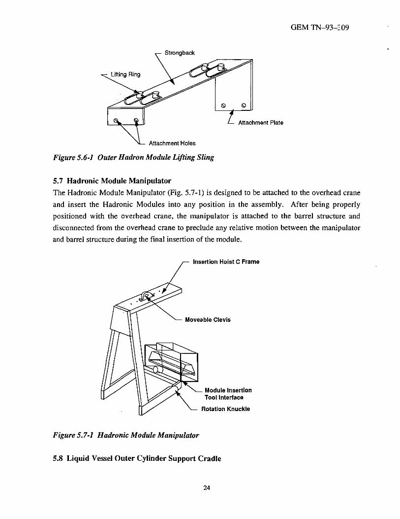
5.7 Hadronic Module Manipulator
The Hadronic Module Manipulator (Fig. 5.7-1) is designed to be attached to the overhead crane
and insert the Hadronic Modules into any position in the assembly. After being properly
positioned with the overhead crane, the manipulator is attached to the barrel structure and
disconnected from the overhead crane to preclude any relative motion between the manipulator
and barrel structure during the final insertion of the module.
Insertion Hoist C Frame
Moveable Clevis
Figure 5.7-1 Hadronic Module Manipulator
Module Insertion Tool Interface
Rotation Knuckle
5.8 Liquid Vessel Outer Cylinder Support Cradle
24

GEM TN-93-309
The liquid vessel outer cylinder support cradle (Fig. 5.8- I) provides support for the outer
cylinder in its installation orientation. It is mounted on rollers to permit the liquid vessel outer
cylinder to be properly positioned in the z-direction for assembly and provides height
adjustments for bolt hole alignment.
Figure 5.8-1 Liquid Vessel Outer Cylinder Support Cradle
5.9 Liquid Vessel Feedthrough Section Support Cradle
The liquid vessel feedthrough section support cradle serves a similar function as the liquid vessel
outer cylinder support cradle and will be similar in appearance (Fig.5.8-1). It provides support
for the feedthrough section in its installation orientation It is also mounted on rollers to permit
the feedthrough section to be properly positioned in the z-direction for assembly and provides
height adjustments for bolt hole alignment. Since the feedthrough section has a limited base to
support itself, the support cradle will also provide vertical stabilization and preclude excessive
out-of-roundness conditions.
25

GEM TN-93-309
5.10 Vacuum Vessel Outer Cylinder Support Cradle
The vacuum vessel support cradle (Fig. 5.8-1) is similar to the liquid vessel outer cylinder
support cradle, providing support for the vacuum vessel outer cylinder in its installation
orientation while the end rings are installed. It is designed to remain stationary and has no height
adjustments.
5.11 Vacuum Vessel Outer Cylinder Rail Assembly Fixture
The Rail Assembly Fixture (Fig.5.11-1) supports the Vacuum Vessel Outer Cylinder on end
rings as it is moved into position around the liquid vessel.
Rail for Vessel Shell Assembly
Barrel LKr Vessel
End Rings
Vacuum Vessel Outer Shell
Mandrel (Floor Support Not Shown)
Figure 5.11-1 Vacuum Vessel Outer Cylinder Rail Assembly Fixture
26
GEM TN-93-309
5.12 Vacuum Vessel Outer Cylinder End Rings
The vacuum vessel end rings (Fig.5. I I- I) are installed on each end of the vacuum vessel outer
cylinder to prevent out-of-roundness and support the cylinder on the assembly rails.
5.13 Inner Barrel Calorimeter Support Cradle
The calorimeter support cradle (Fig. 5. I 3-1) is designed to carry the full weight of the inner
barrel calorimeter and includes provisions for roll transfer into the scintillating barrel in the
Experimental Hall. It is mounted on rollers to permit the vacuum vessel outer cylinder to be
properly positioned in the z-direction for assembly and provides height adjustments for bolt hole
alignment. It also has a set of rails which can be raised to engage the support stanchions and
accept the full load of the inner barrel. The rollers permit the entire unit to be moved to the shaft
for installation. The height of the cradle will be designed to assure that the rails in the
Scintillating Barrel and the Inner Barrel are aligned when the rollers are removed from the
cradle.
5.14 Vacuum Vessel End Plate Assembly Lifting Sling
The vacuum vessel end plate assembly lifting sling (Fig. 5.14-1) attaches to the end plate
assembly, allowing it to be lifted with the overhead crane and positioned for bolting to the outer
vacuum cylinder.
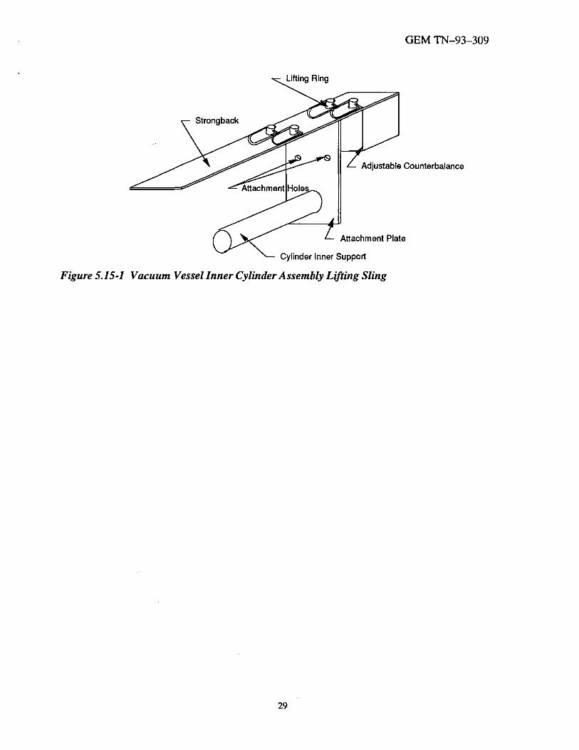
5.15 Vacuum Vessel Inner Cylinder Assembly Lifting Sling
The vacuum vessel inner cylinder assembly lifting sling (Fig. 5.15-1) attaches to the inner
cylinder assembly, allowing it to be lifted with the overhead crane and positioned for bolting to
the outer vacuum cylinder.
5.16 Electronic Test Set
The electronic test set provides for electrical continuity and high voltage testing of all Hadronic
and EM Modules.
27

Vacuum Shell
/ ,
Rail Support
Support Stanchions
Calorimeter Support Cradle
GEM TN-93-309
Figure 5.13-1 Preparation of Calorimeter Support Cradle for Load Transfer
Lifting Lug
Attachment Holes 0
0
0
Figure 5.14-1 Vacuum Vessel End Plate Assembly Lifting Sling
28
Strong back
GEM TN-93-309
Adjustable Counterbalance
Attachment Plate
Cylinder Inner Support
Figure 5.15-1 Vacuum Vessel Inner Cylinder Assembly Lifting Sling
29