general information section contents bi-flex installation
TRANSCRIPT

1
SECTION CONTENTS
General InformatIon
www.elcoconstruction.com
©2021 ELCO – REV. a
ANCHOR MATERIALS• 300 series (18-8) stainless head and
shank and hardened steel tapping threads and drill point
DIAMETER• #8, #10, #12
• 1/4"
HEAD STYLES• Hex Washer Head (HWH)
• Pan Head (PPH)
• Pancake Head (PPCKH)
• Undercut Flat Head (PUFH)
• Flat Head (PFH)
FINISH• Stalgard GB (Galvanic Barrier) coating
CODE LISTEDICC-eS eSr-4367
WOOD-TO-STEEL
BI-FLEX
®
GENERAL INFORMATION
BI-FLEX®
Bi-metal Self-Drilling Structural Screws
PRODUCT DESCRIPTION
Bi-Flex structural screws are bi-metal self-drilling tapping screws that provide the corrosion resistance of 300 series stainless steel and the efficiency of drill screws. Bi-Flex screws are suitable for use in both steel and aluminum.
GENERAL APPLICATIONS AND USES
• Steel-to-steel connections
• aluminum-to-steel connections
• aluminum-to-aluminum connections
• Wood-to-steel connections
FEATURES AND BENEFITS
+ High strength, ductility and reliabliity
+ Immune to hydrogen assisted stress corrosion cracking (HaSCC)
+ Higher corrosion resistance compared with carbon steel and 410 series stainless steel fasteners
+ Stalgard GB coating creates greater galvanic compatibility in dissimilar metal applications, including connections involving aluminum
+ 18-8 stainless compatible with pressure treated lumber
APPROVALS AND LISTINGS
• International Code Council, Evaluation Service (ICC-ES), ESR-4367
• Code compliant with the International Building Code/International Residential Code: 2018 IBC/IRC, 2012 IBC/IRC, and 2009 IBC/IRC
• City of Los angeles, Supplement for 2020 LaBC/LaRC (in ESR-4367)
• Tested in accordance with aISI S905 and ICC-ES aC500 for attaching Miscellaneous Building Materials to Steel
• City of Los angeles, Research Report RR 25886
GUIDE SPECIFICATIONS
05 05 23 – Metal Fastenings, 09 22 16.23 – Fasteners. Fasteners shall be Bi-Flex as supplied by Elco Construction Products, Towson, MD. Fasteners shall be installed with published instructions and the authority Having Jurisdiction.
General Information.........................1Installation Specifications ..............2Performance Data ............................3Ordering Information .......................8
Hardened steel point and tapping threads
300 series stainless steel head and shank
Stalgard® GB coating provides a barrier to resist galvanic corrosion between dissimilar metals
IdentificationThe head marking consists of the number "3"
above the ELCO® logo as shown below.
Hex Washer Head Flat, Pan and Pancake Head
2
InStallatIon SpeCIfICatIonS
1-800-435-7213
©20
21 E
LCO
– R
EV. a
BI-FL
EX®
INSTALLATION SPECIFICATIONS
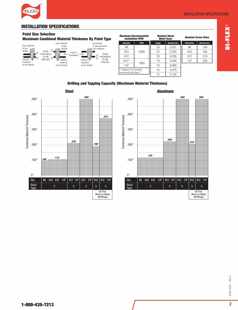
Point Size SelectionMaximum Combined Material Thickness By Point Type
Maximum Recommended Installation RPM
Diameter RPM
#8
2500#10
#12
#12**1800
1/4"** applies to #12 diameter screws with point type 5
Nominal Sheet Metal Sizes
Gauge Decimal (in.)
25 0.021
22 0.030
20 0.036
18 0.048
16 0.060
14 0.075
12 0.105
Nominal Screw Sizes
Thread Dia. Decimal (in.)
#8 .164
#10 .190
#12 .216
1/4" .250
Drilling and Tapping Capacity (Maximum Material Thickness)
Steel Aluminum
Dia.
Point Type
.500"
.400"
.300"
.200"
.100"
0"
.100" .110"
.230".188"
.375"
Com
bine
d M
ater
ial T
hick
ness
#8 #10 #12 1/4"
2 3 5 3 5
#12 1/4" #12 1/4" #10 #12 1/4"
Bi-FlexWood-to-Metal
(W/Wings)
.500"
Dia.
Point Type
.500"
.400"
.300"
.200"
.100"
0"
.125"
.250".210"
Com
bine
d M
ater
ial T
hick
ness
#8 #10 #12 1/4"
2 3 5 3 5
#12 1/4" #12 1/4" #10 #12 1/4"
Bi-FlexWood-to-Metal
(W/Wings)
.500" .500"

3
performanCe Data
www.elcoconstruction.com
©2021 ELCO – REV. a
PERFORMANCE DATA
Fastener Strengths1,2,3,4,5,6,7
Description Head Styles
Tension (lbf) Shear (lbf) Minimum Torsional Strength (in-lbs)
Ultimate ASD LRFD Ultimate ASD LRFD
#8-18 HWH 1,580 525 790 1,120 370 560 45
#8-18 PPH 1,375 455 685 1,045 345 520 32
#10-16 HWH 1,845 615 920 1,280 425 640 48
#10-16 PPH, PPCKH, PFH 1,755 585 875 1,405 465 700 43
#12-14 HWH 2,625 875 1,310 1,950 650 975 95
#12-14 PUFH, PPCKH 2,185 725 1,090 1,525 505 760 73
#12-24 HWH 2,730 910 1,365 2,280 760 1,140 95
#12-24 PFH 2,390 795 1,195 1,840 610 920 73
1/4"-14 HWH 3,455 1,150 1,725 2,675 890 1,335 135
1/4"-20 HWH 4,120 1,370 2,060 2,860 950 1,430 135
1/4"-20 PUFH, PFH 3,405 1,135 1,700 2,550 850 1,275 108
1. Ultimate strengths are based on laboratory tests.
2. allowable (aSD) strengths are based on a safety factor, Ω, of 3.00 in accordance with ICC-ES aC118 and aISI S100-16.
3. Design (LRFD) strengths are based on a resistance factor, f, of 0.50 in accordance with ICC-ES aC118 and aISI S100-16.
4. For aSD tension connections, the lower of the aSD tension strength, aSD pull-out strength and aSD pull-over strength must be used for design.
5. For LRFD tension connections, the lower of the LRFD tension strength, LRFD pull-out strength and LRFD pull-over strength must be used for design.
6. For aSD shear connections, the lower of the aSD Shear (Bearing) Capacity and the aSD Fastener Shear Strength must be used for design.
7. For LRFD shear connections, the lower of the LRFD Shear (Bearing) Capacity and the LRFD Fastener Shear Strength must be used for design.
Ultimate Shear (Bearing) Capacity of Screw Connections in Steel, lbf1,2
Diameter Head StyleSteel Thickness (Lapped Sheets/Bars)
18-18 Ga. 16-16 Ga. 14-14 Ga. 12-12 Ga. 1/8" - 1/8" 3/16" - 3/16"
#8-18 HWH, PPH 805 - - - - -
#10-16 HWH, PPCKH, PFH 865 1,210 1,690 - - -
#12-14 HWH, PPCKH, PUFH 925 1,290 1,805 2,755 - -
#12-24 HWH 925 1,290 1,805 2,755 3,280 4,920
1/4"-14 HWH 995 1,390 1,940 3,190 - -
1/4"-20 HWH 995 1,390 1,940 3,190 3,795 5,695
1. Ultimate strengths are based on calculations in accordance with aISI S100-16.
2. Ultimate load capacities must be reduced by a minimum safety factor to determine allowable loads (aSD) or by a load resistance factor to determine strength design capacities (LRFD).
Allowable (ASD) Shear (Bearing) Capacity of Screw Connections in Steel, lbf1,2,3,4,5,6
Diameter Head StyleSteel Thickness (Lapped Sheets/Bars)
18-18 Ga. 16-16 Ga. 14-14 Ga. 12-12 Ga. 1/8" - 1/8" 3/16" - 3/16"
#8-18 HWH, PPH 270 - - - - -
#10-16 HWH, PPCKH, PFH 290 405 565 - - -
#12-14 HWH, PPCKH, PUFH 310 430 600 920 - -
#12-24 HWH 310 430 600 920 1,095 1,640
1/4"-14 HWH 330 465 645 1,065 - -
1/4"-20 HWH 330 465 645 1,065 1,265 1,900
1. allowable (aSD) strengths are based on a safety factor, Ω=3.00, determined in accordance with aISI S100-16.
2. Values are based on steel members with with a minimum tensile strength of Fu = 45 ksi.
3. allowable (aSD) Shear (Bearing) capacities for other member thicknesses may be determined by interpolating within the table.
4. For aSD shear connections, the lower of the aSD Shear (Bearing) Capacity and the aSD Fastener Shear Strength must be used for design.
5. For steel with a minimum tensile strength Fu ≥ 58 ksi, multiply tabulated values by 1.29 and for steel with a minimum tensile strength Fu ≥ 65 ksi steel, multiply tabulated values by 1.44.
6. The first number is the thickness of steel in contact with the screw head, the second number is the thickness of the steel not in contact with the screw head.
BI-FLEX
®

4
performanCe Data
1-800-435-7213
©20
21 E
LCO
– R
EV. a
Design (LRFD) Shear (Bearing) Capacity of Screw Connections in Steel, lbf 1,2,3,4,5,6
Diameter Head StylesSteel Thickness (Lapped Sheets/ Bars)
18-18 Ga. 16-16 Ga. 14-14 Ga. 12-12 Ga. 1/8" - 1/8" 3/16" - 3/16"
#8-18 HWH, PPH 405 - - - - -
#10-16 HWH, PPCKH, PFH 435 605 845 - - -
#12-14 HWH, PPCKH, PUFH 460 645 900 1,380 - -
#12-24 HWH 460 645 900 1,380 1,640 2,460
1/4"-14 HWH 495 695 970 1,595 - -
1/4"-20 HWH 495 695 970 1,595 1,900 2,850
1. Design (LRFD) strengths are based on a safety factor, f = 0.50 determined in accordance with aISI S100-16.
2. Values are based on steel members with a minimum tensile strength of Fu = 45 ksi.
3. Design (LRFD) Shear (Bearing) capacities for other member thicknesses may be determined by interpolating within the table.
4. For LRFD shear connections, the lower of the LRFD Shear (Bearing) Capacity and the LRFD Fastener Shear Strength must be used for design.
5. For steel with a minimum tensile strength Fu ≥ 58 ksi, multiply tabulated values by 1.29 and for steel with a minimum tensile strength Fu ≥ 65 ksi steel, multiply tabulated values by 1.44.
6. The first number is the thickness of steel in contact with the screw head, the second number is the thickness of the steel not in contact with the screw head.
Ultimate Tension Pull-Out Capacity of Screw Connections in Steel, lbf1,2
Diameter Point TypeSteel Thickness
18 Ga. 16 Ga. 14 Ga. 12 Ga. 1/8" 3/16" 1/4"
#8-18 #2 300 335 525 855 - - -
#10-16 #2 275 405 475 835 - - -
#10-16 #3 - 370 410 745 965 1,185 -
#10-16 w/wings #3 - 350 - - 1,360 - -
#12-14 #2 315 450 535 920 - - -
#12-14 #3 250 405 480 825 1,215 1,940 -
#12-24 #5 - - - - - 1,635 2,160
#12-24 w/wings #5 - 350 - - 1,140 - 1,525
1/4"-14 #2 370 530 650 1,100 - - -
1/4"-20 #3 - 410 470 865 1,575 2,860 -
1/4"-20 w/wings #5 - 250 - - 950 - 2,105
1/4"-20 #5 - - - - - - 2,390
1. Ultimate strengths are based on laboratory tests.
2. Ultimate load capacities must be reduced by a minimum safety factor to determine allowable loads (aSD) or by a load resistance factor to determine strength design capacities (LRFD).
Allowable Tension Pull-Out Capacity of Screw Connections in Steel, lbf1,2,3,4,5
Diameter Point TypeSteel Thickness
18 Ga. 16 Ga. 14 Ga. 12 Ga. 1/8" 3/16" 1/4"
#8-18 #2 100 110 175 285 - - -
#10-16 #2 90 135 160 280 - - -
#10-16 #3 - 125 135 250 320 395 -
#10-16 w/wings #3 - 110 - - 500 [6] - -
#12-14 #2 105 150 180 305 - - -
#12-14 #3 85 135 160 275 405 645 -
#12-24 #5 - - - - - 545 720
#12-24 w/wings #5 - 90 - - 380 [6] - 565
1/4"-14 #2 125 175 215 365 - - -
1/4"-20 #3 - 135 155 290 525 955 -
1/4"-20 w/wings #5 - 55 - - 385 [6] - 780
1/4"-20 #5 - - - - - - 795
1. Unless otherwise noted, allowable (aSD) strengths are based on a safety factor, Ω=3.00, determined in accordance with ICC-ES aC118 and aISI S100-16.
2. Values are based on steel members with a minimum tensile strength of Fu = 45 ksi.
3. allowable (aSD) pull-out capacities for other member thicknesses may be deterimined by interpolating within the table.
4. For aSD tension connections, the lower of the aSD tension strength, aSD pull-out strength and aSD pull-over strength must be used for design.
5. Unless otherwise noted, for 18 gauge through 1/4" thick steel with a minimum tensile strength Fu ≥ 52 ksi, multiply tabulated values by 1.15; when Fu ≥ 58 ksi, multiply tabulated values by 1.29. For 18 gauge through 1/8" thick steel, when Fu ≥ 65 ksi steel, multiply tabulated values by 1.44.
6. allowable (aSD) strengths are based on a safety factor, Ω, determined in accordance with ICC-ES aC500 and aISI S100-16. For steel with a minimum tensile strength Fu ≥ 52 ksi, multiply tabulated values by 1.15.
BI-FL
EX®
5
performanCe Data
www.elcoconstruction.com
©2021 ELCO – REV. a
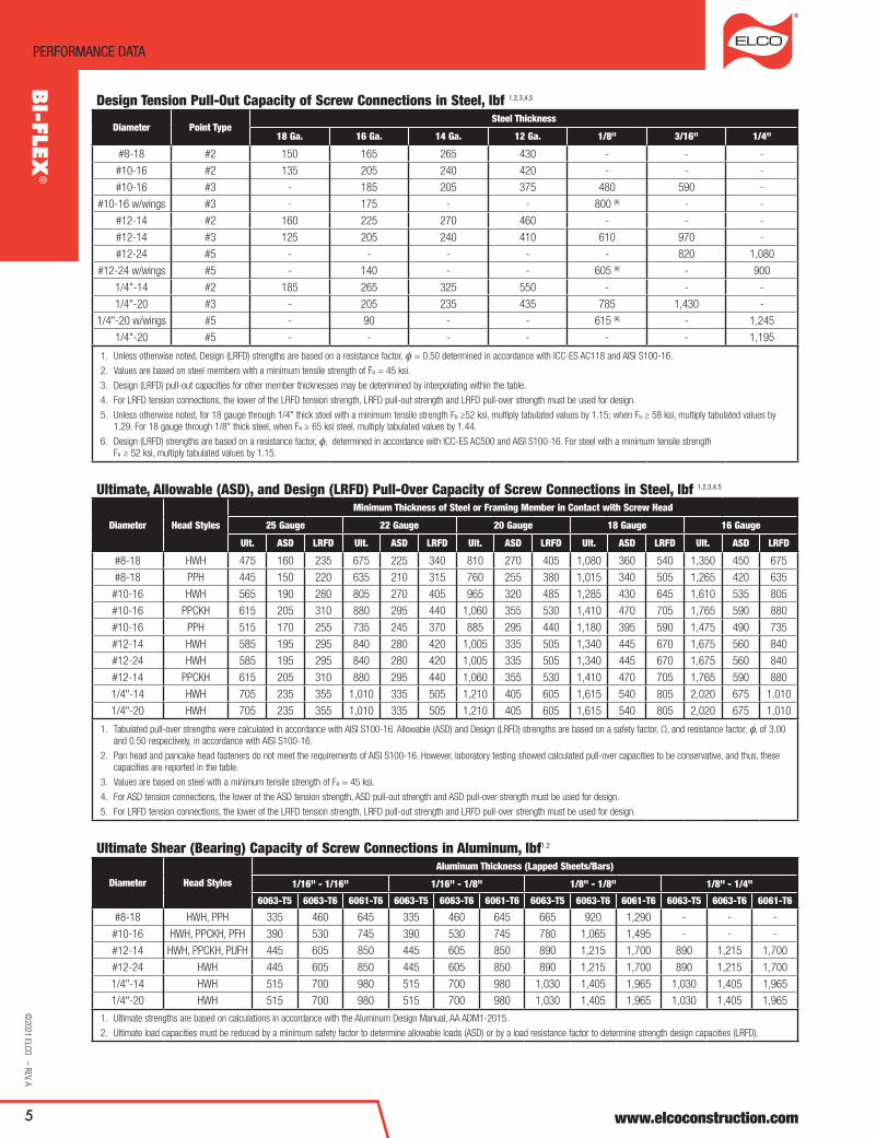
Design Tension Pull-Out Capacity of Screw Connections in Steel, lbf 1,2,3,4,5
Diameter Point TypeSteel Thickness
18 Ga. 16 Ga. 14 Ga. 12 Ga. 1/8" 3/16" 1/4"
#8-18 #2 150 165 265 430 - - -
#10-16 #2 135 205 240 420 - - -
#10-16 #3 - 185 205 375 480 590 -
#10-16 w/wings #3 - 175 - - 800 [6] - -
#12-14 #2 160 225 270 460 - - -
#12-14 #3 125 205 240 410 610 970 -
#12-24 #5 - - - - - 820 1,080
#12-24 w/wings #5 - 140 - - 605 [6] - 900
1/4"-14 #2 185 265 325 550 - - -
1/4"-20 #3 - 205 235 435 785 1,430 -
1/4"-20 w/wings #5 - 90 - - 615 [6] - 1,245
1/4"-20 #5 - - - - - - 1,195
1. Unless otherwise noted, Design (LRFD) strengths are based on a resistance factor, f = 0.50 determined in accordance with ICC-ES aC118 and aISI S100-16.
2. Values are based on steel members with a minimum tensile strength of Fu = 45 ksi.
3. Design (LRFD) pull-out capacities for other member thicknesses may be deterimined by interpolating within the table.
4. For LRFD tension connections, the lower of the LRFD tension strength, LRFD pull-out strength and LRFD pull-over strength must be used for design.
5. Unless otherwise noted, for 18 gauge through 1/4" thick steel with a minimum tensile strength Fu ≥52 ksi, multiply tabulated values by 1.15; when Fu ≥ 58 ksi, multiply tabulated values by 1.29. For 18 gauge through 1/8" thick steel, when Fu ≥ 65 ksi steel, multiply tabulated values by 1.44.
6. Design (LRFD) strengths are based on a resistance factor, f, determined in accordance with ICC-ES aC500 and aISI S100-16. For steel with a minimum tensile strength Fu ≥ 52 ksi, multiply tabulated values by 1.15.
Ultimate, Allowable (ASD), and Design (LRFD) Pull-Over Capacity of Screw Connections in Steel, lbf 1,2,3,4,5
Diameter Head Styles
Minimum Thickness of Steel or Framing Member in Contact with Screw Head
25 Gauge 22 Gauge 20 Gauge 18 Gauge 16 Gauge
Ult. ASD LRFD Ult. ASD LRFD Ult. ASD LRFD Ult. ASD LRFD Ult. ASD LRFD
#8-18 HWH 475 160 235 675 225 340 810 270 405 1,080 360 540 1,350 450 675
#8-18 PPH 445 150 220 635 210 315 760 255 380 1,015 340 505 1,265 420 635
#10-16 HWH 565 190 280 805 270 405 965 320 485 1,285 430 645 1,610 535 805
#10-16 PPCKH 615 205 310 880 295 440 1,060 355 530 1,410 470 705 1,765 590 880
#10-16 PPH 515 170 255 735 245 370 885 295 440 1,180 395 590 1,475 490 735
#12-14 HWH 585 195 295 840 280 420 1,005 335 505 1,340 445 670 1,675 560 840
#12-24 HWH 585 195 295 840 280 420 1,005 335 505 1,340 445 670 1,675 560 840
#12-14 PPCKH 615 205 310 880 295 440 1,060 355 530 1,410 470 705 1,765 590 880
1/4"-14 HWH 705 235 355 1,010 335 505 1,210 405 605 1,615 540 805 2,020 675 1,010
1/4"-20 HWH 705 235 355 1,010 335 505 1,210 405 605 1,615 540 805 2,020 675 1,010
1. Tabulated pull-over strengths were calculated in accordance with aISI S100-16. allowable (aSD) and Design (LRFD) strengths are based on a safety factor, Ω, and resistance factor, f, of 3.00 and 0.50 respectively, in accordance with aISI S100-16.
2. Pan head and pancake head fasteners do not meet the requirements of aISI S100-16. However, laboratory testing showed calculated pull-over capacities to be conservative, and thus, these capacities are reported in the table.
3. Values are based on steel with a minimum tensile strength of Fu = 45 ksi.
4. For aSD tension connections, the lower of the aSD tension strength, aSD pull-out strength and aSD pull-over strength must be used for design.
5. For LRFD tension connections, the lower of the LRFD tension strength, LRFD pull-out strength and LRFD pull-over strength must be used for design.
Ultimate Shear (Bearing) Capacity of Screw Connections in Aluminum, lbf1,2
Diameter Head Styles
Aluminum Thickness (Lapped Sheets/Bars)
1/16" - 1/16" 1/16" - 1/8" 1/8" - 1/8" 1/8" - 1/4"
6063-T5 6063-T6 6061-T6 6063-T5 6063-T6 6061-T6 6063-T5 6063-T6 6061-T6 6063-T5 6063-T6 6061-T6
#8-18 HWH, PPH 335 460 645 335 460 645 665 920 1,290 - - -
#10-16 HWH, PPCKH, PFH 390 530 745 390 530 745 780 1,065 1,495 - - -
#12-14 HWH, PPCKH, PUFH 445 605 850 445 605 850 890 1,215 1,700 890 1,215 1,700
#12-24 HWH 445 605 850 445 605 850 890 1,215 1,700 890 1,215 1,700
1/4"-14 HWH 515 700 980 515 700 980 1,030 1,405 1,965 1,030 1,405 1,965
1/4"-20 HWH 515 700 980 515 700 980 1,030 1,405 1,965 1,030 1,405 1,965
1. Ultimate strengths are based on calculations in accordance with the aluminum Design Manual, aa aDM1-2015.
2. Ultimate load capacities must be reduced by a minimum safety factor to determine allowable loads (aSD) or by a load resistance factor to determine strength design capacities (LRFD).
BI-FLEX
®
6
performanCe Data
1-800-435-7213
©20
21 E
LCO
– R
EV. a
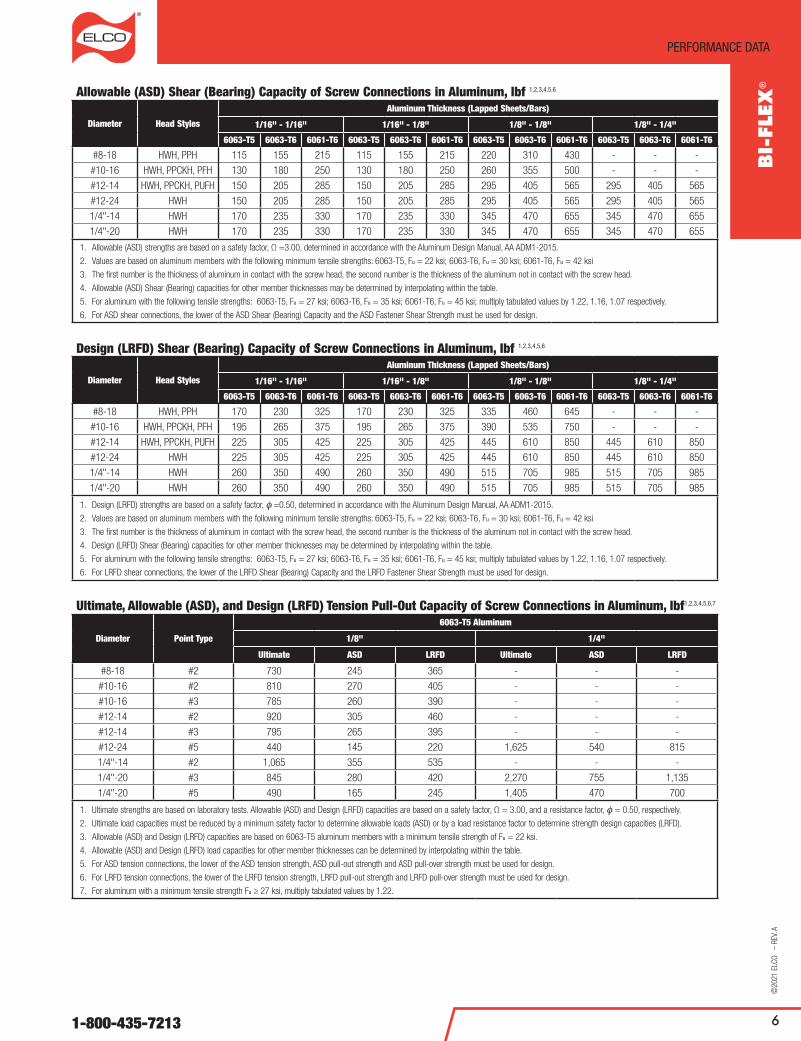
Allowable (ASD) Shear (Bearing) Capacity of Screw Connections in Aluminum, lbf 1,2,3,4,5,6
Diameter Head Styles
Aluminum Thickness (Lapped Sheets/Bars)
1/16" - 1/16" 1/16" - 1/8" 1/8" - 1/8" 1/8" - 1/4"
6063-T5 6063-T6 6061-T6 6063-T5 6063-T6 6061-T6 6063-T5 6063-T6 6061-T6 6063-T5 6063-T6 6061-T6
#8-18 HWH, PPH 115 155 215 115 155 215 220 310 430 - - -
#10-16 HWH, PPCKH, PFH 130 180 250 130 180 250 260 355 500 - - -
#12-14 HWH, PPCKH, PUFH 150 205 285 150 205 285 295 405 565 295 405 565
#12-24 HWH 150 205 285 150 205 285 295 405 565 295 405 565
1/4"-14 HWH 170 235 330 170 235 330 345 470 655 345 470 655
1/4"-20 HWH 170 235 330 170 235 330 345 470 655 345 470 655
1. allowable (aSD) strengths are based on a safety factor, Ω =3.00, determined in accordance with the aluminum Design Manual, aa aDM1-2015.
2. Values are based on aluminum members with the following minimum tensile strengths: 6063-T5, Fu = 22 ksi; 6063-T6, Fu = 30 ksi; 6061-T6, Fu = 42 ksi
3. The first number is the thickness of aluminum in contact with the screw head, the second number is the thickness of the aluminum not in contact with the screw head.
4. allowable (aSD) Shear (Bearing) capacities for other member thicknesses may be determined by interpolating within the table.
5. For aluminum with the following tensile strengths: 6063-T5, Fu = 27 ksi; 6063-T6, Fu = 35 ksi; 6061-T6, Fu = 45 ksi; multiply tabulated values by 1.22, 1.16, 1.07 respectively.
6. For aSD shear connections, the lower of the aSD Shear (Bearing) Capacity and the aSD Fastener Shear Strength must be used for design.
Design (LRFD) Shear (Bearing) Capacity of Screw Connections in Aluminum, lbf 1,2,3,4,5,6
Diameter Head Styles
Aluminum Thickness (Lapped Sheets/Bars)
1/16" - 1/16" 1/16" - 1/8" 1/8" - 1/8" 1/8" - 1/4"
6063-T5 6063-T6 6061-T6 6063-T5 6063-T6 6061-T6 6063-T5 6063-T6 6061-T6 6063-T5 6063-T6 6061-T6
#8-18 HWH, PPH 170 230 325 170 230 325 335 460 645 - - -
#10-16 HWH, PPCKH, PFH 195 265 375 195 265 375 390 535 750 - - -
#12-14 HWH, PPCKH, PUFH 225 305 425 225 305 425 445 610 850 445 610 850
#12-24 HWH 225 305 425 225 305 425 445 610 850 445 610 850
1/4"-14 HWH 260 350 490 260 350 490 515 705 985 515 705 985
1/4"-20 HWH 260 350 490 260 350 490 515 705 985 515 705 985
1. Design (LRFD) strengths are based on a safety factor, f =0.50, determined in accordance with the aluminum Design Manual, aa aDM1-2015.
2. Values are based on aluminum members with the following minimum tensile strengths: 6063-T5, Fu = 22 ksi; 6063-T6, Fu = 30 ksi; 6061-T6, Fu = 42 ksi
3. The first number is the thickness of aluminum in contact with the screw head, the second number is the thickness of the aluminum not in contact with the screw head.
4. Design (LRFD) Shear (Bearing) capacities for other member thicknesses may be determined by interpolating within the table.
5. For aluminum with the following tensile strengths: 6063-T5, Fu = 27 ksi; 6063-T6, Fu = 35 ksi; 6061-T6, Fu = 45 ksi; multiply tabulated values by 1.22, 1.16, 1.07 respectively.
6. For LRFD shear connections, the lower of the LRFD Shear (Bearing) Capacity and the LRFD Fastener Shear Strength must be used for design.
Ultimate, Allowable (ASD), and Design (LRFD) Tension Pull-Out Capacity of Screw Connections in Aluminum, lbf1,2,3,4,5,6,7
Diameter Point Type
6063-T5 Aluminum
1/8" 1/4"
Ultimate ASD LRFD Ultimate ASD LRFD
#8-18 #2 730 245 365 - - -
#10-16 #2 810 270 405 - - -
#10-16 #3 785 260 390 - - -
#12-14 #2 920 305 460 - - -
#12-14 #3 795 265 395 - - -
#12-24 #5 440 145 220 1,625 540 815
1/4"-14 #2 1,065 355 535 - - -
1/4"-20 #3 845 280 420 2,270 755 1,135
1/4"-20 #5 490 165 245 1,405 470 700
1. Ultimate strengths are based on laboratory tests. allowable (aSD) and Design (LRFD) capacities are based on a safety factor, Ω = 3.00, and a resistance factor, f = 0.50, respectively.
2. Ultimate load capacities must be reduced by a minimum safety factor to determine allowable loads (aSD) or by a load resistance factor to determine strength design capacities (LRFD).
3. allowable (aSD) and Design (LRFD) capacities are based on 6063-T5 aluminum members with a minimum tensile strength of Fu = 22 ksi.
4. allowable (aSD) and Design (LRFD) load capacities for other member thicknesses can be determined by interpolating within the table.
5. For aSD tension connections, the lower of the aSD tension strength, aSD pull-out strength and aSD pull-over strength must be used for design.
6. For LRFD tension connections, the lower of the LRFD tension strength, LRFD pull-out strength and LRFD pull-over strength must be used for design.
7. For aluminum with a minimum tensile strength Fu ≥ 27 ksi, multiply tabulated values by 1.22.
BI-FL
EX®

7
performanCe Data
www.elcoconstruction.com
©2021 ELCO – REV. a
Ultimate Pull-Over Capacity of Screw Connections in Aluminum, lbf1,2
Diameter Head Styles
Minimum Thickness of Aluminum in Contact with Screw Head
1/32" 1/16" 1/8"
6063-T5 6063-T6 6061-T6 6063-T5 6063-T6 6061-T6 6063-T5 6063-T6 6061-T6
#8 - 18 HWH 190 300 425 440 685 965 1,095 1,710 2,395#8 - 18 PPH 180 285 400 420 655 915 1,050 1,645 2,300#10 - 16 HWH 225 350 495 505 790 1,105 1,225 1,910 2,680#10 - 16 PPCKH 245 380 535 540 845 1,185 1,295 2,030 2,840#10 - 16 PPH 205 325 455 470 735 1,030 1,155 1,805 2,525#12 - 14 HWH 230 365 510 520 810 1,140 1,255 1,960 2,745#12 - 24 HWH 230 365 510 520 810 1,140 1,255 1,960 2,745#12 - 14 PPCKH 245 380 535 540 845 1,185 1,295 2,030 2,8401/4 - 14 HWH 275 430 605 605 945 1,325 1,425 2,225 3,1151/4 - 20 HWH 275 430 605 605 945 1,325 1,425 2,225 3,115
1. Ultimate strengths are based on calculations in accordance with the aluminum Design Manual, aa aDM1-2015.2. Ultimate load capacities must be reduced by a minimum safety factor to determine allowable loads (aSD) or by a load resistance factor to determine strength design capacities (LRFD).
Allowable (ASD) Pull-Over Capacity of Screw Connections in Aluminum, lbf1,2,3,4,5,6
Diameter Head Styles
Minimum Thickness of Aluminum in Contact with Screw Head
1/32" 1/16" 1/8"
6063-T5 6063-T6 6061-T6 6063-T5 6063-T6 6061-T6 6063-T5 6063-T6 6061-T6
#8 - 18 HWH 65 100 140 145 230 320 365 570 800#8 - 18 PPH 60 95 135 140 220 305 350 550 770#10 - 16 HWH 75 120 165 170 265 370 410 640 895#10 - 16 PPCKH 80 130 180 180 285 395 435 675 945#10 - 16 PPH 70 110 150 155 245 345 385 600 840#12 - 14 HWH 80 120 170 175 270 380 420 655 915#12 - 24 HWH 80 120 170 175 270 380 420 655 915#12 - 14 PPCKH 80 130 180 180 285 395 435 675 9451/4 - 14 HWH 90 145 200 200 315 440 475 740 1,0401/4 - 20 HWH 90 145 200 200 315 440 475 740 1,040
1. allowable strengths are based on a safety factor, Ω = 3.00, determined in accordance with the aluminum Design Manual, aa aDM1-2015.2. Values are based on aluminum members with the following minimum yield strengths: 6063-T5, Fy = 16 ksi; 6063-T6, Fy = 25 ksi; 6061-T6, Fy = 35 ksi3. allowable (aSD) pull-over capacities for other member thicknesses may be determined by interpolating within the table.4. For aluminum with the following yield strengths: 6063-T5, Fy = 21 ksi; 6063-T6, Fy = 31 ksi; 6061-T6, Fy = 40 ksi; multiply tabulated values by 1.31, 1.24, 1.14 respectively. 5. Tabulated pull over capacities are applicable to aluminum that has been self drilled by the screw fastener and for pre-drilled aluminum members with clearance holes sizes of 0.177, 0.201,
0.228 and 0.266 for #8, #10, #12 and 1/4" screws, respectively.6. For LRFD tension connections, the lower of the LRFD tension strength, LRFD pull-out strength and LRFD pull-over strength must be used for design.
Design (LRFD) Pull-Over Capacity of Screw Connections in Aluminum, lbf1,2,3,4,5,6
Diameter Head Styles
Minimum Thickness of Aluminum in Contact with Screw Head
1/32" 1/16" 1/8"
6063-T5 6063-T6 6061-T6 6063-T5 6063-T6 6061-T6 6063-T5 6063-T6 6061-T6
#8 - 18 HWH 95 150 215 220 345 485 550 855 1,200#8 - 18 PPH 90 145 200 210 330 460 525 825 1,150#10 - 16 HWH 115 175 250 255 395 555 615 955 1,340#10 - 16 PPCKH 125 190 270 270 425 595 650 1,015 1,420#10 - 16 PPH 105 165 230 235 370 515 580 905 1,265#12 - 14 HWH 115 185 255 260 405 570 630 980 1,375#12 - 24 HWH 115 185 255 260 405 570 630 980 1,375#12 - 14 PPCKH 125 190 270 270 425 595 650 1,015 1,4201/4 - 14 HWH 140 215 305 305 475 665 715 1,115 1,5601/4 - 20 HWH 140 215 305 305 475 665 715 1,115 1,560
1. Design (LRFD) strengths are based on a resistance factor, f = 0.50, determined in accordance with the aluminum Design Manual, aa aDM1-2015.2. Values are based on aluminum members with the following minimum yield strengths: 6063-T5, Fy = 16 ksi; 6063-T6, Fy = 25 ksi; 6061-T6, Fy = 35 ksi3. Design (LRFD) pull-over capacities for other member thicknesses may be determined by interpolating within the table.4. For aluminum with the following yield strengths: 6063-T5, Fy = 21 ksi; 6063-T6, Fy = 31 ksi; 6061-T6, Fy = 40 ksi; multiply tabulated values by 1.31, 1.24, 1.14 respectively. 5. Tabulated pull over capacities are applicable to aluminum that has been self drilled by the screw fastener and for pre-drilled aluminum members with clearance holes sizes of 0.177, 0.201,
0.228 and 0.266 for #8, #10, #12 and 1/4" screws, respectively.6. For LRFD tension connections, the lower of the LRFD tension strength, LRFD pull-out strength and LRFD pull-over strength must be used for design.
Lap Shear Tension Pull-Out Tension Pull-Over
BI-FLEX
®

8
orDerInG InformatIon
1-800-435-7213
©20
21 E
LCO
– R
EV. a
ORDERING INFORMATION
Bi-Flex Self-Drilling Structural Screws
Cat. No. 5Description
(Diameter- TPI x Nominal Length)
Point Type FinishMaximum
Load-Bearing Length1
(in.)
Minimum Protrusion
Length2 (in.)
Nominal Head Diameter3
(in.)
Nominal Head Height4
(in.)Qty / Carton
#8 Diameter, 1/4" Hex Washer Head
EaJ100 #8-18 X 3/4" #2 Stalgard GB 0.156 19/32" 0.335 0.140 5,000EaJ102 #8-18 X 1" #2 Stalgard GB 0.406 19/32" 0.335 0.140 5,000
#8 Diameter, #2 Phillips Pan Head
EaX100 #8-18 X 3/4" #2 Stalgard GB 0.156 19/32" 0.315 0.110 5,000EaX102 #8-18 X 1" #2 Stalgard GB 0.406 19/32" 0.315 0.110 5,000
#10 Diameter, 5/16" Hex Washer Head
EaJ110 #10-16 X 3/4" #2 Stalgard GB 0.250 1/2" 0.400 0.160 5,000EaJ120 #10-16 X 1" #2 Stalgard GB 0.500 1/2" 0.400 0.160 5,000EaJ140 #10-16 X 1-1/2" #2 Stalgard GB 1.000 1/2" 0.400 0.160 2,500
#10 Diameter, #2 Phillips Pan Head
EaX110 #10 - 16 x 3/4" #2 Stalgard GB 0.250 1/2" 0.365 0.130 5,000EaX120 #10 - 16 x 1" #2 Stalgard GB 0.500 1/2" 0.365 0.130 5,000
#10 Diameter, #2 Phillips Pancake Head
EBN300 #10 - 16 x 1" #2 Stalgard GB 0.500 1/2" 0.435 0.075 4,000#12 Diameter, 5/16" Hex Washer Head
EaJ185 #12 - 14 x 1" #2 Stalgard GB 0.406 19/32" 0.415 0.200 3,000EaJ190 #12 - 14 x 1" #3 Stalgard GB 0.406 19/32" 0.415 0.200 4,000EaJ200 #12 - 14 x 1-1/4" #3 Stalgard GB 0.656 19/32" 0.415 0.200 2,500EaJ215 #12 - 14 x 1-1/2" #2 Stalgard GB 0.906 19/32" 0.415 0.200 2,500EaJ220 #12 - 14 x 1-1/2" #3 Stalgard GB 0.906 19/32" 0.415 0.200 2,500EaJ320 #12 - 24 x 1-1/2" #5 Stalgard GB 0.500 1" 0.415 0.200 2,500EaJ240 #12 - 14 x 2" #2 Stalgard GB 1.406 19/32" 0.415 0.200 1,500EaJ340 #12 - 24 x 2" #5 Stalgard GB 1.000 1" 0.415 0.200 2,000EaJ260 #12 - 14 x 2-1/2" #3 Stalgard GB 1.906 19/32" 0.415 0.200 1,000
#12 Diameter, #3 Phillips Undercut Flat Head
EBN200 #12 - 14 x 1" #2 Stalgard GB 0.406 19/32" 0.415 0.090 4,000EBN220 #12 - 14 x 1-1/4" #2 Stalgard GB 0.656 19/32" 0.415 0.090 2,500EBN240 #12 - 14 x 1-1/2" #2 Stalgard GB 0.906 19/32" 0.415 0.090 2,500
#12 Diameter, #2 Phillips Pancake Head
EBN320 #12 - 14 X 1" #3 Stalgard GB 0.406 19/32" 0.435 0.075 4,0001/4" Diameter, 3/8" Hex Washer Head
EaJ415 1/4" - 14 x 1" #2 Stalgard GB 0.406 19/32" 0.500 0.250 2,500EaJ540 1/4" - 20 x 1" #3 Stalgard GB 0.406 19/32" 0.500 0.250 2,500EaJ430 1/4" - 14 x 1-1/2" #2 Stalgard GB 0.906 19/32" 0.500 0.250 1,000EaJ580 1/4" - 20 x 1-1/2" #3 Stalgard GB 0.906 19/32" 0.500 0.250 1,000EaJ600 1/4" - 20 x 1-1/2" #5 Stalgard GB 0.500 1" 0.500 0.250 1,000EaJ445 1/4" - 14 x 2" #2 Stalgard GB 1.406 19/32" 0.500 0.250 1,500EaJ610 1/4" - 20 x 2" #3 Stalgard GB 1.406 19/32" 0.500 0.250 1,500EaJ615 1/4" - 20 x 2" #5 Stalgard GB 1.000 1" 0.500 0.250 1,500EaJ640 1/4" - 20 x 2-1/2" #3 Stalgard GB 1.906 19/32" 0.500 0.250 1,000
EaJ650 [6] 1/4" - 20 x 3" #3 Stalgard GB 2.406 19/32" 0.500 0.250 500EaJ630 1/4" - 20 x 3" #5 Stalgard GB 2.000 1" 0.500 0.250 500
EaJ660 [6] 1/4" - 20 x 4" #3 Stalgard GB 3.406 19/32" 0.500 0.250 500EaJ670 1/4" - 20 x 4" #5 Stalgard GB 3.000 1" 0.500 0.250 500
EaJ675 [7] 1/4" - 20 x 5" #5 Stalgard GB 4.000 1" 0.500 0.250 250EaJ680 [7] 1/4" - 20 x 6" #5 Stalgard GB 5.000 1" 0.500 0.250 250
EaJ690C [8] 1/4" - 20 x 8" #5 Stalgard GB 7.000 1" 0.500 0.250 1501/4" Diameter, #3 Phillips Undercut Flat Head
EBN630 [9] 1/4" - 20 x 3" #3 Stalgard GB 2.406 19/32" 0.480 0.100 500EBN640 [9] 1/4" - 20 x 4" #3 Stalgard GB 3.406 19/32" 0.480 0.100 500
1. The Maximum Load Bearing Length is calculated by subtracting the Minimum Protrusion Length from the Nominal Length of the fastener.2. Minimum Protrusion Length is the length that allows the hardened steel tip and lead threads to protrude out of the back side of the supporting material. 3. Nominal head diameter is the diameter of the integral washer on hex washer head fasteners. 4. Nominal head height includes the thickness of the integral washer on hex washer head fasteners. 5. Unless otherwise noted, all fasteners are fully threaded. Usable thread length is equal to the maximum load bearing length. 6. Partially threaded fastener with a usable thread length of 1.60".7. Partially threaded fastener with a usable thread length of 2.60".8. Partially threaded fastener with a usable thread length of 2.15".9. Partially threaded fastener with a usable thread length of 1.35".
BI-FL
EX®
9
orDerInG InformatIon
www.elcoconstruction.com
©2021 ELCO – REV. a
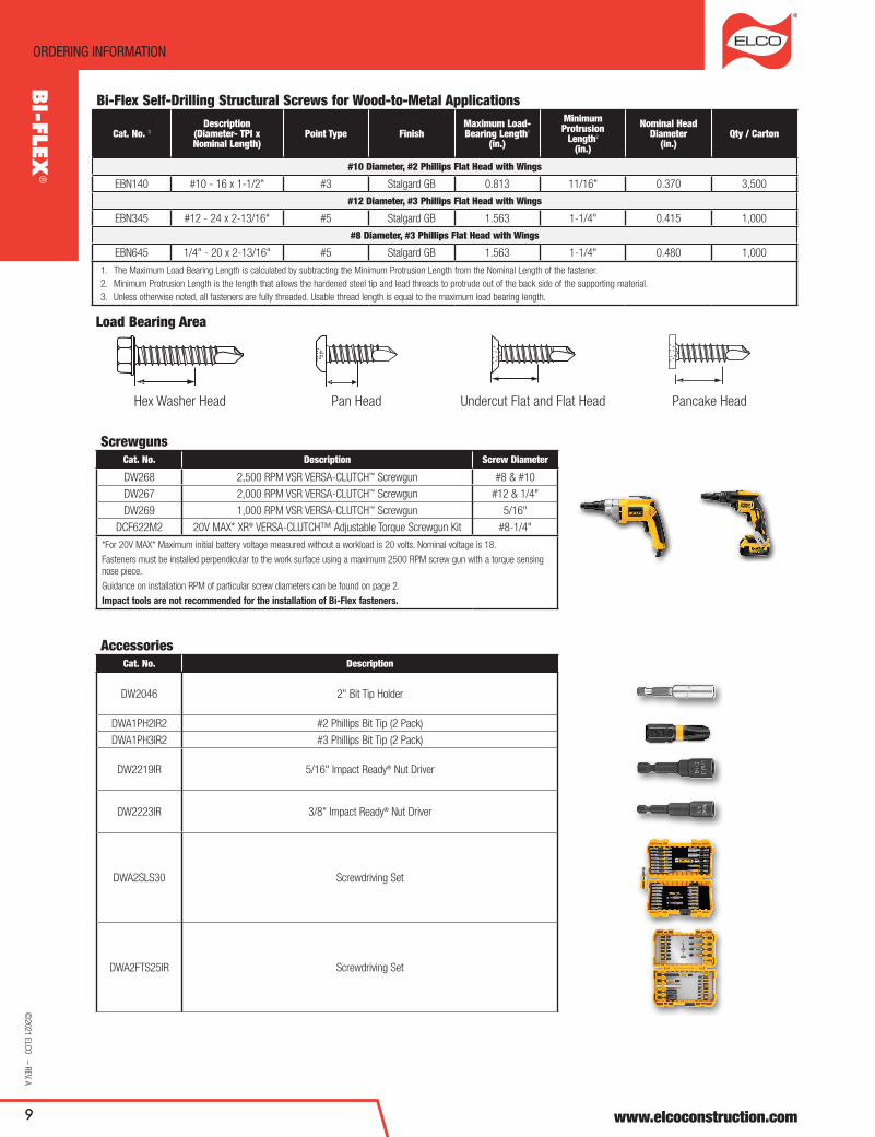
Bi-Flex Self-Drilling Structural Screws for Wood-to-Metal Applications
Cat. No. 3Description
(Diameter- TPI x Nominal Length)
Point Type FinishMaximum Load-Bearing Length1
(in.)
Minimum Protrusion
Length2 (in.)
Nominal Head Diameter
(in.)Qty / Carton
#10 Diameter, #2 Phillips Flat Head with Wings
EBN140 #10 - 16 x 1-1/2" #3 Stalgard GB 0.813 11/16" 0.370 3,500
#12 Diameter, #3 Phillips Flat Head with Wings
EBN345 #12 - 24 x 2-13/16" #5 Stalgard GB 1.563 1-1/4" 0.415 1,000
#8 Diameter, #3 Phillips Flat Head with Wings
EBN645 1/4" - 20 x 2-13/16" #5 Stalgard GB 1.563 1-1/4" 0.480 1,000
1. The Maximum Load Bearing Length is calculated by subtracting the Minimum Protrusion Length from the Nominal Length of the fastener.2. Minimum Protrusion Length is the length that allows the hardened steel tip and lead threads to protrude out of the back side of the supporting material. 3. Unless otherwise noted, all fasteners are fully threaded. Usable thread length is equal to the maximum load bearing length.
Load Bearing Area
Hex Washer Head Pan Head Undercut Flat and Flat Head Pancake Head
ScrewgunsCat. No. Description Screw Diameter
DW268 2,500 RPM VSR VERSa-CLUTCH™ Screwgun #8 & #10
DW267 2,000 RPM VSR VERSa-CLUTCH™ Screwgun #12 & 1/4"
DW269 1,000 RPM VSR VERSa-CLUTCH™ Screwgun 5/16"
DCF622M2 20V MaX* XR® VERSa-CLUTCH™ adjustable Torque Screwgun Kit #8-1/4"
*For 20V MaX* Maximum initial battery voltage measured without a workload is 20 volts. Nominal voltage is 18.
Fasteners must be installed perpendicular to the work surface using a maximum 2500 RPM screw gun with a torque sensing nose piece.
Guidance on installation RPM of particular screw diameters can be found on page 2.
Impact tools are not recommended for the installation of Bi-Flex fasteners.
AccessoriesCat. No. Description
DW2046 2" Bit Tip Holder
DWa1PH2IR2 #2 Phillips Bit Tip (2 Pack)
DWa1PH3IR2 #3 Phillips Bit Tip (2 Pack)
DW2219IR 5/16" Impact Ready® Nut Driver
DW2223IR 3/8" Impact Ready® Nut Driver
DWa2SLS30 Screwdriving Set
DWa2FTS25IR Screwdriving Set
BI-FLEX
®