generalizing demonstrated manipulation tasks
TRANSCRIPT

Generalizing Demonstrated ManipulationTasks
Nancy S. Pollard1,3 and Jessica K. Hodgins2,3
1 Brown University, Providence RI 02912, USA2 Carnegie Mellon University, Pittsburgh PA 15213, USA3 ATR Human Information Science Laboratories, Kyoto 619-0288, Japan
Abstract. Captured human motion data can provide a rich source of examples ofsuccessful manipulation strategies. General techniques for adapting these examplesfor use in robotics are not yet available, however, in part because the problem to besolved by the robot will rarely be the same as that in the human demonstration. Thispaper considers the problem of adapting a human demonstration of a quasistaticmanipulation task to new objects and friction conditions (Figure 1). We arguethat a manipulation plan is similar to a demonstration if it involves the identicalnumber of contacts and if the applied contact wrenches follow similar trajectories.Based on this notion of similarity, we present an algorithm that uses the humandemonstration to constrain the solution space to a set of manipulation plans similarto the demonstration. Our algorithm provides guarantees on maximum task forcesand flexibility in contact placement. Results for the task of tumbling large, heavyobjects show that manipulation plans similar to a demonstration can be synthesizedfor a variety of object sizes, shapes, and coefficients of friction. Experimental resultswith a humanoid robot show that the approach produces natural-looking motionin addition to effective manipulation plans.
Fig. 1. (Top) Human demonstration of a tumbling task. (Bottom) The demonstra-tion has been adapted to a new object geometry and to the robot kinematics.
2 Nancy S. Pollard and Jessica K. Hodgins
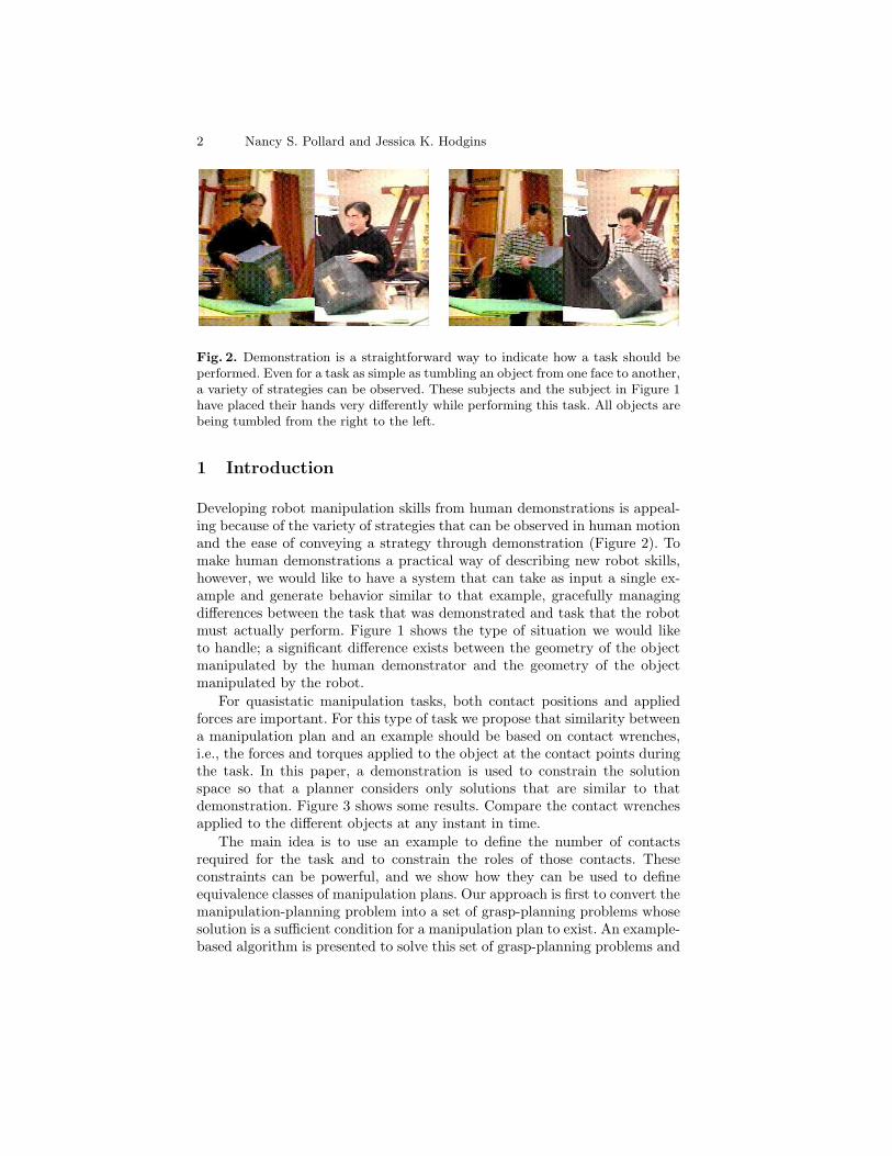
Fig. 2. Demonstration is a straightforward way to indicate how a task should beperformed. Even for a task as simple as tumbling an object from one face to another,a variety of strategies can be observed. These subjects and the subject in Figure 1have placed their hands very differently while performing this task. All objects arebeing tumbled from the right to the left.
1 Introduction
Developing robot manipulation skills from human demonstrations is appeal-ing because of the variety of strategies that can be observed in human motionand the ease of conveying a strategy through demonstration (Figure 2). Tomake human demonstrations a practical way of describing new robot skills,however, we would like to have a system that can take as input a single ex-ample and generate behavior similar to that example, gracefully managingdifferences between the task that was demonstrated and task that the robotmust actually perform. Figure 1 shows the type of situation we would liketo handle; a significant difference exists between the geometry of the objectmanipulated by the human demonstrator and the geometry of the objectmanipulated by the robot.
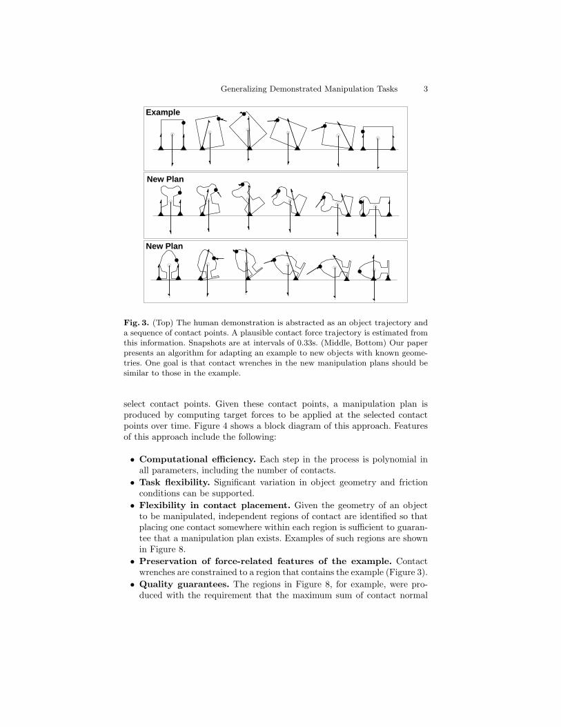
For quasistatic manipulation tasks, both contact positions and appliedforces are important. For this type of task we propose that similarity betweena manipulation plan and an example should be based on contact wrenches,i.e., the forces and torques applied to the object at the contact points duringthe task. In this paper, a demonstration is used to constrain the solutionspace so that a planner considers only solutions that are similar to thatdemonstration. Figure 3 shows some results. Compare the contact wrenchesapplied to the different objects at any instant in time.
The main idea is to use an example to define the number of contactsrequired for the task and to constrain the roles of those contacts. Theseconstraints can be powerful, and we show how they can be used to defineequivalence classes of manipulation plans. Our approach is first to convert themanipulation-planning problem into a set of grasp-planning problems whosesolution is a sufficient condition for a manipulation plan to exist. An example-based algorithm is presented to solve this set of grasp-planning problems and
Generalizing Demonstrated Manipulation Tasks 3
Example
New Plan
New Plan
Fig. 3. (Top) The human demonstration is abstracted as an object trajectory anda sequence of contact points. A plausible contact force trajectory is estimated fromthis information. Snapshots are at intervals of 0.33s. (Middle, Bottom) Our paperpresents an algorithm for adapting an example to new objects with known geome-tries. One goal is that contact wrenches in the new manipulation plans should besimilar to those in the example.
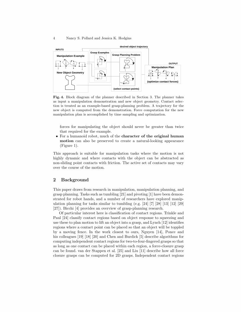
select contact points. Given these contact points, a manipulation plan isproduced by computing target forces to be applied at the selected contactpoints over time. Figure 4 shows a block diagram of this approach. Featuresof this approach include the following:
• Computational efficiency. Each step in the process is polynomial inall parameters, including the number of contacts.
• Task flexibility. Significant variation in object geometry and frictionconditions can be supported.
• Flexibility in contact placement. Given the geometry of an objectto be manipulated, independent regions of contact are identified so thatplacing one contact somewhere within each region is sufficient to guaran-tee that a manipulation plan exists. Examples of such regions are shownin Figure 8.
• Preservation of force-related features of the example. Contactwrenches are constrained to a region that contains the example (Figure 3).
• Quality guarantees. The regions in Figure 8, for example, were pro-duced with the requirement that the maximum sum of contact normal
4 Nancy S. Pollard and Jessica K. Hodgins
INPUTS
New Object Geometry
Manipulation Example
desired object trajectory
Grasp ExamplesGrasp Planning Problem
(select contact points)
OUTPUT
(optimize contact forces)
Manipulation Plan
Fig. 4. Block diagram of the planner described in Section 3. The planner takesas input a manipulation demonstration and new object geometry. Contact selec-tion is treated as an example-based grasp-planning problem. A trajectory for thenew object is computed from the demonstration. Force computation for the newmanipulation plan is accomplished by time sampling and optimization.
forces for manipulating the object should never be greater than twicethat required for the example.
• For a humanoid robot, much of the character of the original humanmotion can also be preserved to create a natural-looking appearance(Figure 1).
This approach is suitable for manipulation tasks where the motion is nothighly dynamic and where contacts with the object can be abstracted asnon-sliding point contacts with friction. The active set of contacts may varyover the course of the motion.
2 Background
This paper draws from research in manipulation, manipulation planning, andgrasp planning. Tasks such as tumbling [21] and pivoting [1] have been demon-strated for robot hands, and a number of researchers have explored manip-ulation planning for tasks similar to tumbling (e.g. [24] [7] [28] [13] [12] [29][27]). Bicchi [4] provides an overview of grasp-planning research.
Of particular interest here is classification of contact regions. Trinkle andPaul [24] classify contact regions based on object response to squeezing anduse these to plan motion to lift an object into a grasp, and Lynch [12] identifiesregions where a contact point can be placed so that an object will be toppledby a moving fence. In the work closest to ours, Nguyen [14], Ponce andhis colleagues [19] [18] [20] and Chen and Burdick [5] describe algorithms forcomputing independent contact regions for two-to-four-fingered grasps so thatas long as one contact can be placed within each region, a force-closure graspcan be found. van der Stappen et al. [25] and Liu [11] describe how all forceclosure grasps can be computed for 2D grasps. Independent contact regions
Generalizing Demonstrated Manipulation Tasks 5
could be extracted from the results of their algorithms. Our paper builds onmany of these ideas to show how contact regions can be constructed, not fromscratch as in previous work, but from an example, so that the contact regionsrepresent a subclass of grasps similar to that example. The key algorithmis an adaptation of Pollard [16] from grasps to manipulation strategies andfrom frictionless contacts to contacts with friction.
Our work also draws on research in learning from demonstration. Previouswork has used one or a combination of two basic approaches. The first is toextract a policy or control strategy directly from the demonstration [2] [10].The second is to extract enough information about the goal and/or task thata planner or learning algorithm can compute such a policy [9] [8] [26] [22].The two approaches can be combined. In this case, the planner somehowmakes use of the detailed information observed in the human demonstration.For example, in learning a pendulum swingup task, Atkeson and Schaal [3]begin by tracking the hand trajectory of the human demonstrator. Theynote that merely tracking observed motion was not effective and present aniterative learning algorithm to successfully duplicate pendulum motion fromthe demonstration.
Our paper relies on a combined approach. In our case, the object trajec-tory and a set of contact points are extracted from the human demonstration.The example cannot be applied directly to a new object, because identicalcontact points may not be available; a new set of contact points must befound that are appropriate for the new object. Our approach differs fromprevious work in that the demonstration is not modified in a local way asin [3], but instead it is used to constrain the space of solutions consideredby a global planner. This tactic is practical for tasks that are not highlydynamic. Our approach gives us many of the advantages of a global plannerwhile keeping the results tied to an example and leading to a computationallyefficient algorithm.
3 Generalizing a Manipulation Example
An example contains a trajectory for the manipulated object and a trajectoryfor each contact (Figure 3, top). Our problem is to adapt the example to a newobject with known geometry, which requires identifying contact points andsolving for contact force targets on the new object. The main idea pursuedhere is to convert the manipulation problem into a grasp-planning problemsuch that a solution to the latter is a sufficient condition for a solution tothe former to exist. Section 3.1 describes how a manipulation problem isconverted to a grasp-planning problem; Sections 3.2 and 3.3 describe howthis problem is solved. The frictionless case is presented first, followed by anextension to contacts with friction. Section 3.4 details how these results areconverted to a manipulation plan.
6 Nancy S. Pollard and Jessica K. Hodgins
cumulative
wrenchesfor task
contactcumulative
wrenchesfor task
contactcumulative
wrenchesfor task
contact
Find contacts that work for bothGiven...
and
contact atground
beginningof motion
end of motionground contact at
EXAMPLE EXAMPLE
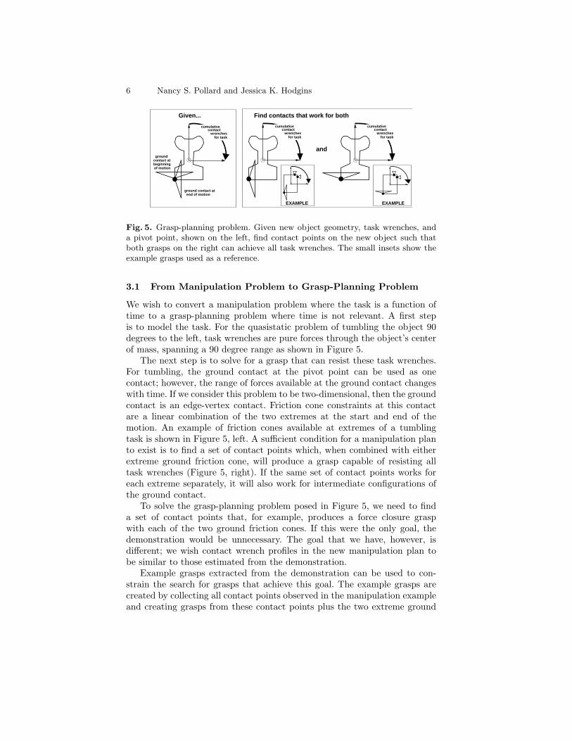
Fig. 5. Grasp-planning problem. Given new object geometry, task wrenches, anda pivot point, shown on the left, find contact points on the new object such thatboth grasps on the right can achieve all task wrenches. The small insets show theexample grasps used as a reference.
3.1 From Manipulation Problem to Grasp-Planning Problem
We wish to convert a manipulation problem where the task is a function oftime to a grasp-planning problem where time is not relevant. A first stepis to model the task. For the quasistatic problem of tumbling the object 90degrees to the left, task wrenches are pure forces through the object’s centerof mass, spanning a 90 degree range as shown in Figure 5.
The next step is to solve for a grasp that can resist these task wrenches.For tumbling, the ground contact at the pivot point can be used as onecontact; however, the range of forces available at the ground contact changeswith time. If we consider this problem to be two-dimensional, then the groundcontact is an edge-vertex contact. Friction cone constraints at this contactare a linear combination of the two extremes at the start and end of themotion. An example of friction cones available at extremes of a tumblingtask is shown in Figure 5, left. A sufficient condition for a manipulation planto exist is to find a set of contact points which, when combined with eitherextreme ground friction cone, will produce a grasp capable of resisting alltask wrenches (Figure 5, right). If the same set of contact points works foreach extreme separately, it will also work for intermediate configurations ofthe ground contact.
To solve the grasp-planning problem posed in Figure 5, we need to finda set of contact points that, for example, produces a force closure graspwith each of the two ground friction cones. If this were the only goal, thedemonstration would be unnecessary. The goal that we have, however, isdifferent; we wish contact wrench profiles in the new manipulation plan tobe similar to those estimated from the demonstration.
Example grasps extracted from the demonstration can be used to con-strain the search for grasps that achieve this goal. The example grasps arecreated by collecting all contact points observed in the manipulation exampleand creating grasps from these contact points plus the two extreme ground
Generalizing Demonstrated Manipulation Tasks 7
friction cones. Example grasps for the demonstration explored in this paperare shown as insets in Figure 5. Each of these grasps is capable of achievingall required task wrenches. If this were not true, the task would have to besegmented into subtasks, each covering a smaller range of object motion.
3.2 Placement of Frictionless Contacts
The grasp-planning problem illustrated in Figure 5 must be solved to selecta discrete set of contact points. Solving this problem requires several steps.First, independent contact regions are computed for each extreme groundfriction cone. Second, these regions are intersected to create independentcontact regions that will work for either grasp. Third, discrete contact pointsare chosen within the regions. After regions have been identified, intersectingthem is trivial, and contact points can be selected as desired by the user(e.g., in the centers of the largest connected region or to achieve a kinematicgoal such as similarity to the original human motion). The difficult part ofthe problem is to identify a set of independent contact regions. This sectiondescribes how regions are computed for a given ground contact friction coneextreme.
When the grasp is frictionless, the algorithm from Pollard [16] can be usedto adapt a grasp to new object geometries by designing wrench space regionsaround the contact wrenches of the example grasp and then projecting theseregions onto a new object. This approach is reviewed below, and Section 3.3describes how it can be extended to contacts with friction.
Equivalence Classes of Contact Configurations. From a given examplegrasp, we wish to define equivalence classes of contact configurations on a newobject. The information extracted from the example grasp is the particularrole ascribed to each contact within that grasp. The idea is that if contacts ona new object can be found to play the same roles, the new grasp is in a way“the same as” the example. This idea can be quantified with the followingconstruction.
Let gi = [f̂i γ(ri× f̂i)]T be the set of contact wrenches for each contact i
of the example grasp, formed from unit normal contact forces f̂i and resultingtorque about the object’s center of mass, (ri× f̂i), where ri is the vector fromobject’s center of mass to the contact point. Torque is scaled by some suitablefactor γ, for example the distance from the object center of mass to the pivotpoint.
Form the convex hull of gi and the zero wrench. Represent it as a collectionof hyperplanes, each expressed as an outward pointing normal nj and distancefrom the wrench space origin dj :
{ [n1, d1], [n2, d2], . . . , [nH , dH ] } = CH{ 0,g1,g2, . . . ,gN} (1)
There are N contact points in the example grasp and H facets in the convexhull. An example set of contact points and the convex hull of those points in
8 Nancy S. Pollard and Jessica K. Hodgins
scale by β / Fmax = 0.35
β = 0.5
g4
fx
fy
g3
g2 g1
[n3, d3] [n1, d1]
[n4, d4]
[n2, d2]
g4
fx
fy
g3
g2 g1
Fmax = 1.41
[n1, d1’ ]
g4
fx
fy
g3
g2 g1
[n1, 0.35*d1’ ]
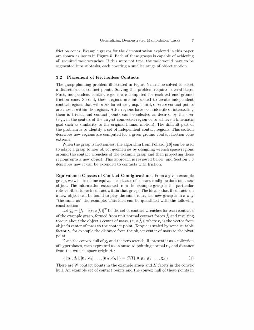
Fig. 6. An example isolates roles of the individual contacts as regions in wrenchspace. This example corresponds to a frictionless grasp of a circular disc with fourevenly spaced contacts. (Left) Contact wrenches gi and the convex hull formedfrom those wrenches. (Center) Move hyperplanes so that they just contain thetask wrench space, which is the black shaded area in the figure, oriented towardforces in the y direction. (Right) Scale hyperplanes by β/Fmax, and highlight unitforce wrench space regions that satisfy Equation 5. The bottom two contacts areassociated with larger regions due to the anisotropy of the task.
a two-dimensional wrench space (a frictionless grasp of a 2D circular disc) isshown in Figure 6, left.
Index set ρi identifies hyperplanes associated with contact i:
ρi = {j : (gi · nj) = dj} (2)
For example, in Figure 6 left, ρ1 = {1, 2}, because g1 is contained in hyper-planes 1 and 2.
Adjust each hyperplane along its normal until it just contains all wrenchesrequired for the given task. For a task that can be represented as a collectionof points sk in wrench space:
d′j = max
(0, max
k(sk · nj)
)(3)
where (sk · nj) is the inner product of wrench space vectors sk and nj . Anexample of this construction is shown in Figure 6 center. The task is the blackshaded area, dominated by a range of forces in the positive y direction.
The maximum sum of contact normal forces required for this task, Fmax,is then:
Fmax =H
maxj=1
d′j
dj(4)
The value of Fmax is 1.41 in the example of Figure 6, because the topmosthyperplane must be scaled by this factor to contain the entire set of taskwrenches within its interior.
Generalizing Demonstrated Manipulation Tasks 9
Any new grasp, defined as the set of contact wrenches g′i, is in equivalence
class β if it satisfies the following collection of inequalities for each contact i:(g′i · nj
)≥ β
Fmaxd′j ∀j ∈ ρi (5)
This equation states that wrench g′i is in the exterior or exactly on all of
the hyperplanes that contained point gi in the convex hull formed from theexample grasp, after these hyperplanes have been adjusted to fit the taskand scaled by β/Fmax. Contact wrench g
′i is meant to correspond directly to
original contact wrench gi. In other words, the two contacts are intended toplay the same roles in their respective grasps. Parameter β allows limits tobe placed on the sum of contact normal forces. Setting β to 0.5, for example,guarantees that in the new grasp the sum of contact normal forces will neverbe greater than twice that required in the example if the task wrenches arethe same as those in the example [15]. Figure 6 right shows an example whereβ is 0.5.
Valid contact regions can now be “painted” onto a new object by sam-pling the object surface, computing the contact wrench associated with eachsurface point and testing whether Equation 5 holds. A different region willbe computed for each contact of the original grasp. These regions are inde-pendent. As long as the new grasp has one contact in each region, we canguarantee that the grasp can exert the task wrenches with a sum of contactnormal forces no greater than 1/β times those of the example grasp. Practi-cally this guarantee is useful for keeping robot joint torques within reasonablelimits.
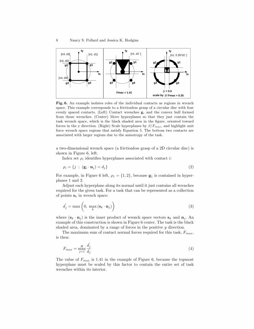
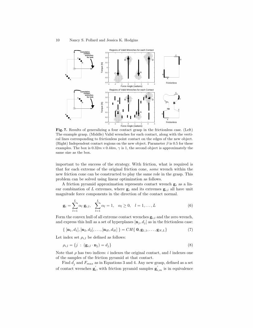
Figure 7 shows an example of a 2D, four-contact, frictionless grasp witha 3D wrench space. The task is to slowly rotate the object 90 degrees tothe left, and wrenches required to support the object during this task arepure forces through the object’s center of mass spanning a 90 degree range.After the grasp is processed as described in Equations 1 through 4, the setof valid wrenches for each contact, which is defined by Equation 5, can becomputed and displayed. Contact force magnitude is arbitrary, and so it isrestricted to one to allow contact wrenches to be plotted in a 2D space of forceangle vs. torque in the center plots. Wrenches corresponding to frictionlesspoint contact on the edges of any new object can be plotted in this samespace. They appear as vertical lines, because force angle does not change asthe contact point moves along the edge. Valid contact regions on the objectoccur when these vertical lines intersect the contact regions. The figures onthe right show contact regions for the example object and an object withmore complex geometry.
3.3 Placement of Contacts with Friction
The approach just described is not adequate for the example shown in Fig-ure 1, or for the large majority of manipulation tasks because friction is
10 Nancy S. Pollard and Jessica K. Hodgins
cumulative
wrenchesfor task
contact
A
B
C
D
-0.3
-0.2
-0.1
0
0.1
0.2
0.3
-3 -2 -1 0 1 2 3 4
Tor
que
(N)
Force Angle (radians)
Regions of Valid Wrenches for each Contact
A
B
C
D
A
B
C
D
Frictionless
cumulative
wrenchesfor task
contact
A
B
C
D
-0.3
-0.2
-0.1
0
0.1
0.2
0.3
-3 -2 -1 0 1 2 3 4
Tor
que
(N)
Force Angle (radians)
Regions of Valid Wrenches for each Contact
A
B
C
D
A
A
B
B
C
C
D
D
Frictionless
Fig. 7. Results of generalizing a four contact grasp in the frictionless case. (Left)The example grasp. (Middle) Valid wrenches for each contact, along with the verti-cal lines corresponding to frictionless point contact on the edges of the new object.(Right) Independent contact regions on the new object. Parameter β is 0.5 for theseexamples. The box is 0.32m×0.44m, γ is 1, the second object is approximately thesame size as the box.
important to the success of the strategy. With friction, what is required isthat for each extreme of the original friction cone, some wrench within thenew friction cone can be constructed to play the same role in the grasp. Thisproblem can be solved using linear optimization as follows.
A friction pyramid approximation represents contact wrench gi as a lin-ear combination of L extremes, where gi and its extremes gi,l all have unitmagnitude force components in the direction of the contact normal.
gi =
L∑
l=1
αl gi,l,
L∑
l=1
αl = 1, αl ≥ 0, l = 1, . . . , L (6)
Form the convex hull of all extreme contact wrenches gi,l and the zero wrench,and express this hull as a set of hyperplanes [nj , dj ] as in the frictionless case:
{ [n1, d1], [n2, d2], . . . , [nH , dH ] } = CH{ 0,g1,1, . . . ,gN,L} (7)
Let index set ρi,l be defined as follows:
ρi,l = {j : (gi,l · nj) = dj} (8)
Note that ρ has two indices: i indexes the original contact, and l indexes oneof the samples of the friction pyramid at that contact.
Find d′j and Fmax as in Equations 3 and 4. Any new grasp, defined as a set
of contact wrenches g′i, with friction pyramid samples g
′i,m is in equivalence
Generalizing Demonstrated Manipulation Tasks 11
class β if the following set of expressions can be solved for all combinationsof contacts i = 1, . . . , N and friction cone extremes l = 1, . . . , L:
[(L∑
m=1
αm g′i,m
)· nj]≥ β
Fmaxd′j ∀j ∈ ρi,l (9)
L∑
m=1
αm = 1 (10)
αm ≥ 0, m = 1, . . . , L (11)
The first expression states that for contact i in the example grasp, for eachfriction cone extreme l, proposed contact i on the new object must be ableto generate a wrench that plays the same role in the grasp. The secondexpression maintains unit magnitude for the force component of g
′i in the
normal direction, and the third expression keeps all g′i within their friction
cones.
For example, a proposed new grasp can be tested for membership in equiv-alence class β by solving this linear system using the simplex method. To dothis, replace β with unknown parameter βi,l and maximize βi,l for each com-bination of indices i and l. The proposed grasp is in equivalence class β if:
Nmini=1
(L
minl=1
βi,l
)≥ β (12)
As in the frictionless case, valid contact regions can be “painted” on thenew object by sampling the object surface, attempting to solve the system inEquations 9 through 11 for a single contact i, for all friction cone extremesl, and checking that
∑l βi,l ≥ β. All of the examples in Section 4 use this
algorithm.
3.4 From Grasp-Planning Results to Manipulation Results
Finally, the manipulation strategy must be extracted from the grasp repre-sentation of the problem. Timing is obtained for the new motion by reusingthe joint angle trajectories captured from the human actor at their origi-nal speed. This decision preserves the dynamics of the robot motion at thepossible expense of the dynamics of the manipulated object.
The orientation trajectory of the new object, θ′(t), can be derived from the
orientation trajectory of the example object, θ(t). Our goal was to duplicateorientation of the example as much as possible, while ensuring that the criticalpoint where the object’s center of mass is just above the pivot occurs at thesame time in each motion. This critical point is important because it is the
12 Nancy S. Pollard and Jessica K. Hodgins
AB
CL
L
L
A B C
AB
CL
L
L
A B C
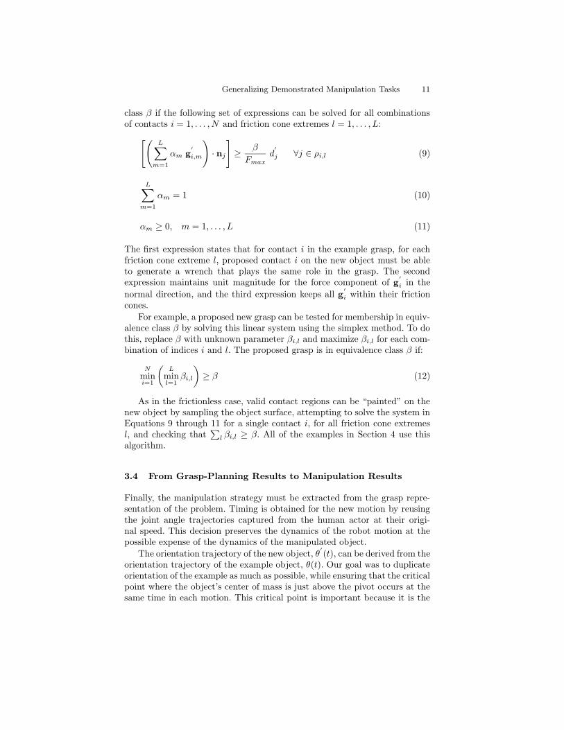
Fig. 8. (Left) Valid aspect ratios for two new objects are represented by a rangeof angles from pivot point to center of mass. (Right) The pivot point is markedwith a solid triangle, and valid independent contact regions for the two contactsare shown. The hand/object coefficient of friction was set to 0.5, and object/groundcoefficient of friction was set to 6. (The table was covered with foam, producinga high coefficient of friction.) Quality parameter β was set to 0.5. Note that theseresults are independent of scale. Length parameter L in the left hand diagram canbe set to any value to reflect the actual size of the object to be manipulated.
point at which applied torque about the pivot point changes direction. Thefollowing expression is used:
θ′(t) =
[ψ +
t
T(φ− ψ)
](θ(t)− π
2
)+π
2(13)
where angle θ is measured as the angle from horizontal of the vector from thepivot point to the object’s center of mass so that the critical point occurs atθ = π/2. Parameters ψ and φ are the required scale factors at the beginningand end of the motion, determined from object geometry, and T is the timerequired for the entire motion.
Forces are estimated by sampling time, computing object orientation fromEquation 13, and optimizing contact forces for that orientation and the givencontact positions. To optimize contact forces, the sum of normal forces appliedat the hand/object contacts is minimized, ignoring the magnitude of theground reaction force. A conservative estimate of the hand/object coefficientof friction is used, as solutions optimized in this way tend to fall on theextremes of the friction cone.
4 Results
Figures 8 and 9 show contact regions computed for new object geometriesby generalizing from the given example. The sizes of the independent con-tact regions vary with geometry, aspect ratio (Figure 8), coefficient of friction
Generalizing Demonstrated Manipulation Tasks 13
= 0.3µ = 0.5β
2 times force
= 0.9µ = 0.5β
2 times force
= 0.5µ = 0.7β
1.4 times force
= 0.5µ = 0.1β
10 times force
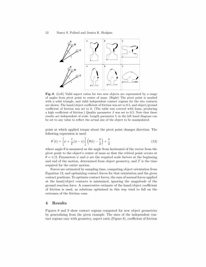
Fig. 9. (Left) Contact regions grow larger as the hand/object coefficient of friction(µ) increases. (Right) Contact regions grow larger as the acceptable amount ofcontact force (1/β times the example) increases.
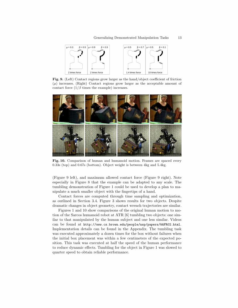
Fig. 10. Comparison of human and humanoid motion. Frames are spaced every0.33s (top) and 0.67s (bottom). Object weight is between 4kg and 5.4kg.
(Figure 9 left), and maximum allowed contact force (Figure 9 right). Noteespecially in Figure 8 that the example can be adapted to any scale. Thetumbling demonstration of Figure 1 could be used to develop a plan to ma-nipulate a much smaller object with the fingertips of a hand.
Contact forces are computed through time sampling and optimization,as outlined in Section 3.4. Figure 3 shows results for two objects. Despitedramatic changes in object geometry, contact wrench trajectories are similar.
Figures 1 and 10 show comparisons of the original human motion to mo-tion of the Sarcos humanoid robot at ATR [6] tumbling two objects: one sim-ilar to that manipulated by the human subject and one less similar. Videoscan be found at http://www.cs.brown.edu/people/nsp/papers/WAFR02.html.Implementation details can be found in the Appendix. The tumbling taskwas executed approximately a dozen times for the box without failures whenthe initial box placement was within a few centimeters of the expected po-sition. This task was executed at half the speed of the human performanceto reduce dynamic effects. Tumbling for the object in Figure 1 was slowed toquarter speed to obtain reliable performance.
14 Nancy S. Pollard and Jessica K. Hodgins
5 Discussion
This paper describes an approach to adapting a single example of a quasistaticmanipulation task to various object geometries and friction conditions. Sig-nificant flexibility was obtained both in geometry of the object and in choiceof contact locations. Experimental results with a humanoid robot show thatthe resulting strategies can be executed reliably. They also retain some of thenatural feel of the original human motion.
One natural question is “why bother with the example motion?” Afterthe problem has been abstracted to the level of contact positions and forces,it lends itself easily to such alternative approaches as global optimization ofcontact configurations over time. Our informal observation is that globallyoptimal solutions frequently do not match strategies actually used by humansubjects, perhaps because we have not adequately captured the optimiza-tion function, if any, in use by the human subject. We believe by combiningplanning and example-based approaches, some good features of both can becaptured. Using analytic generalization gives us valid contact regions, whichprovide flexibility to avoid joint limits or other potential problems such asareas where the object is slippery or fragile. Because contact regions are con-structed from an example, contact placement is often very similar to thatof the example, which may be advantageous when the robot and the humandemonstrator have similar kinematics and workspaces. By design of the algo-rithm, contact wrenches are constrained to be within some region containingthose of the example, and so we have a much stronger argument for similarityof the results to the example than do planners which consider task goal only.
This approach will work for any object where Equations 9 through 11can be solved for all contacts. These equations provide a mapping between acontact index and a set of acceptable object features, although this mappingis not in a practical form at present. Expressing these equations as sets ofacceptable object features would be useful for evaluating the generality of agiven strategy, for collecting/evaluating a motion database, and for selectingbetween strategies when faced with a new manipulation problem. We areworking toward a practical mapping between wrench space regions and objectfeatures.
Computation times for the examples in this paper are on the order of mil-liseconds. However, sampling the object surface to find good contact regionswill be more expensive for truly 3D objects. We are working on a projectionalgorithm along the lines of Ponce et al. [20] to address this problem.
More complex manipulation tasks will almost certainly require more struc-ture and extensions to the techniques presented here. Manipulation tasks withmany contact transitions (e.g., remove a hand and place it somewhere else)may need to be segmented into subtasks. Manipulation tasks with slidingcontacts, which are common in human manipulation of objects, cannot beaddressed with this approach as it stands. Complex contacts (e.g., contacts
Generalizing Demonstrated Manipulation Tasks 15
in concavities and area contacts) seem to be similar to contact with frictionbut have not yet been explored.
We are excited about the results to-date and anticipate that the basicapproach will prove general: that quasistatic manipulation can be treatedas a single task domain, a library of example motions collected within thisdomain, and these examples adapted to new situations as needed, allowingus to take better advantage of the interesting variety of strategies exhibitedin human behavior.
Acknowledgments
We would like to thank Mike Erdmann and Matt Mason for helpful discus-sions on this problem, Darrin Bentivegna, Gordon Cheng, Marcia Riley, andStefan Schaal for assistance with the robot experiments, and Chris Atkesonfor assistance in both areas. The robot and support for this work were pro-vided by ATR Human Information Science Laboratories. Additional supportwas provided for Pollard by NSF grant CCR-0093072 and for Hodgins byNSF grant IIS-0196089.
Appendix: Implementation Details
The human demonstration was captured using a commercially available op-tical motion capture system from Vicon [23]. We used a standard marker setwith 35 14mm markers for whole body motion, supplemented with two ad-ditional markers on each hand and three markers on the box. The additionalmarkers made it possible to extract hand/object contact points during themotion.
The Sarcos robot at ATR (DB) [6] was used to demonstrate the exampleand new manipulation plans. To obtain joint trajectories for the robot, theraw marker data from the motion capture session was mapped to a humanskeleton, scaled to the robot degrees of freedom and joint limits as describedin [17], and adjusted using inverse kinematics to achieve and maintain contactpoints at desired locations on the object.
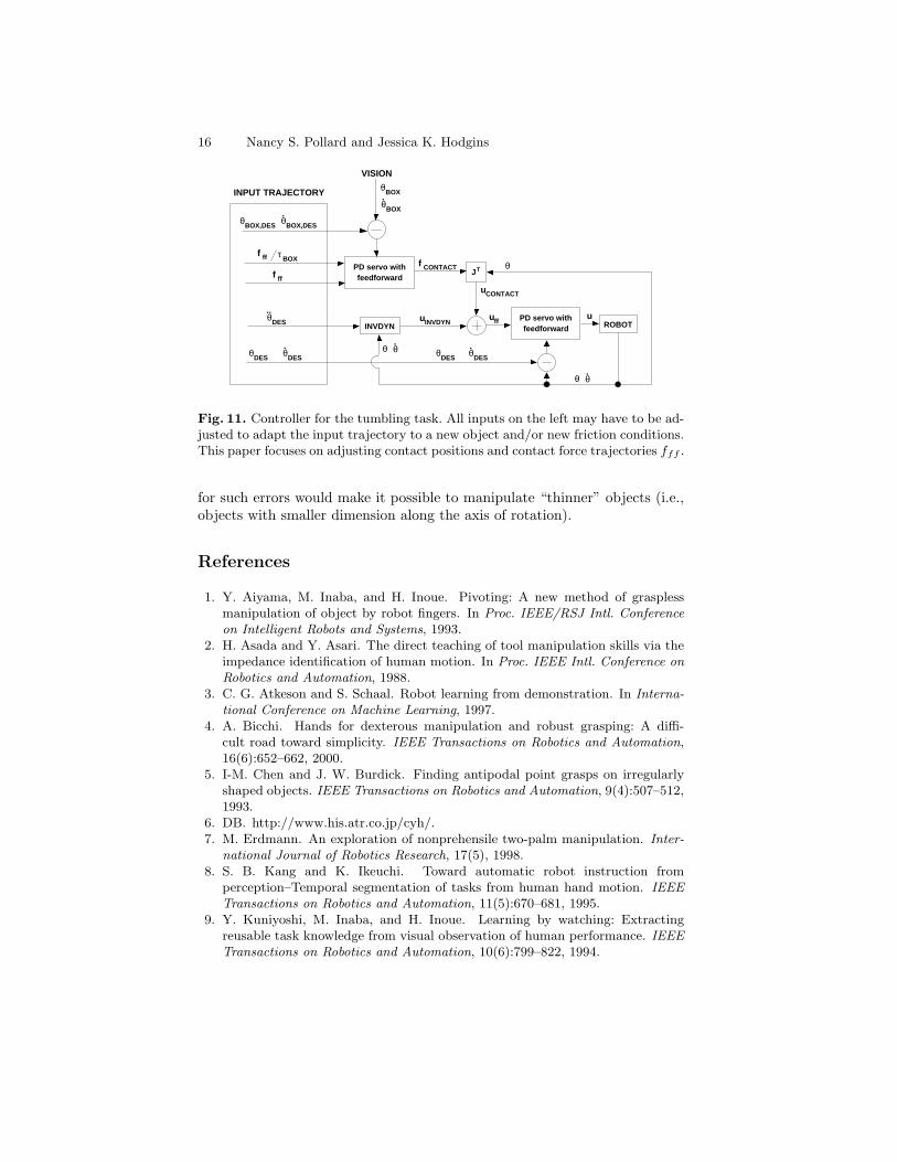
The control system used for these examples is shown in Figure 11. Theinput trajectory was specified as a set of kinematic parameters and a set ofparameters relating to contact between the robot and the object. Specifically,inputs are robot joint angles and derivatives (θDES , θ̇DES , θ̈DES), box orien-tation (θBOX,DES , θ̇BOX,DES), contact forces (fff ), and the ratio of contactforce magnitudes to torque about the box pivot point (fff/τBOX). Two low-gain PD servos are used for control, one that uses visual feedback to maintainbox state and one that uses position sensing at the joints to track the joint an-gle trajectory. The servo associated with box state controls the magnitude offeedforward contact forces to implement a torsional spring and damper aboutthe box pivot point. Out-of-plane orientation errors are ignored. Correction
16 Nancy S. Pollard and Jessica K. Hodgins
PD servo with feedforward
θBOX
.θBOX
ROBOT
uCONTACT
f ff
BOXτf ff
INVDYN
θ.
θ
JTPD servo with feedforward
f CONTACT
uffuINVDYN
θ.
θ
θDES
..
θBOX,DES θBOX,DES
.
θDES
.θDES θDES θDES
.
u
VISION
INPUT TRAJECTORY
θ
Fig. 11. Controller for the tumbling task. All inputs on the left may have to be ad-justed to adapt the input trajectory to a new object and/or new friction conditions.This paper focuses on adjusting contact positions and contact force trajectories fff .
for such errors would make it possible to manipulate “thinner” objects (i.e.,objects with smaller dimension along the axis of rotation).
References
1. Y. Aiyama, M. Inaba, and H. Inoue. Pivoting: A new method of grasplessmanipulation of object by robot fingers. In Proc. IEEE/RSJ Intl. Conferenceon Intelligent Robots and Systems, 1993.
2. H. Asada and Y. Asari. The direct teaching of tool manipulation skills via theimpedance identification of human motion. In Proc. IEEE Intl. Conference onRobotics and Automation, 1988.
3. C. G. Atkeson and S. Schaal. Robot learning from demonstration. In Interna-tional Conference on Machine Learning, 1997.
4. A. Bicchi. Hands for dexterous manipulation and robust grasping: A diffi-cult road toward simplicity. IEEE Transactions on Robotics and Automation,16(6):652–662, 2000.
5. I-M. Chen and J. W. Burdick. Finding antipodal point grasps on irregularlyshaped objects. IEEE Transactions on Robotics and Automation, 9(4):507–512,1993.
6. DB. http://www.his.atr.co.jp/cyh/.7. M. Erdmann. An exploration of nonprehensile two-palm manipulation. Inter-
national Journal of Robotics Research, 17(5), 1998.8. S. B. Kang and K. Ikeuchi. Toward automatic robot instruction from
perception–Temporal segmentation of tasks from human hand motion. IEEETransactions on Robotics and Automation, 11(5):670–681, 1995.
9. Y. Kuniyoshi, M. Inaba, and H. Inoue. Learning by watching: Extractingreusable task knowledge from visual observation of human performance. IEEETransactions on Robotics and Automation, 10(6):799–822, 1994.
Generalizing Demonstrated Manipulation Tasks 17
10. S. Liu and H. Asada. Transferring manipulative skills to robots: Representationand acquisition of tool manipulative skills using a process dynamics model.Journal of Dynamic Systems, Measurement, and Control, 114:220–228, June1992.
11. Y.-H. Liu. Computing n-finger form-closure grasps on polygonal objects. In-ternational Journal of Robotics Research, 19(2):149–158, February 2000.
12. K. M. Lynch. Toppling manipulation. In Proc. IEEE Intl. Conference onRobotics and Automation, 1999.
13. K. M. Lynch and M. T. Mason. Dynamic nonprehensile manipulation: Control-lability, planning, and experiments. International Journal of Robotics Research,18(1):64–92, January 1999.
14. V. Nguyen. Constructing force-closure grasps. International Journal of RoboticsResearch, 7(3):3–16, June 1988.
15. N. S. Pollard. Parallel methods for synthesizing whole-hand grasps from gener-alized prototypes. Technical Report AI-TR-1464, MIT AI Lab., January 1994.
16. N. S. Pollard. Synthesizing grasps from generalized prototypes. In Proc. IEEEIntl. Conference on Robotics and Automation, April 1996.
17. N. S. Pollard, J. K. Hodgins, M. J. Riley, and C. G. Atkeson. Adapting humanmotion for the control of a humanoid robot. In Proc. IEEE Intl. Conferenceon Robotics and Automation, May 2002.
18. J. Ponce and B. Faverjon. On computing three-finger force-closure grasps ofpolygonal objects. IEEE Transactions on Robotics and Automation, 11(6):868–881, 1995.
19. J. Ponce, D. Stam, and B. Faverjon. On computing force-closure grasps ofcurved two-dimensional objects. International Journal of Robotics Research,12(3):263–273, June 1993.
20. J. Ponce, S. Sullivan, A. Sudsang, J.-D. Boissonnat, and J.-P. Merlet. On com-puting four-finger equilibrium and force-closure grasps of polyhedral objects.International Journal of Robotics Research, 16(1):11–35, February 1997.
21. N. Sawasaki, M. Inaba, and H. Inoue. Tumbling objects using a multi-fingeredrobot. In Proc. 20th ISIR, 1989.
22. S. Schaal, C. G. Atkeson, and S. Vijayakumar. Scalable techniques from non-parametric statistics for real-time robot learning. Applied Intelligence, (inpress).
23. Vicon Motion Systems. http://www.vicon.com/.24. J. C. Trinkle and R. P. Paul. Planning for dexterous manipulation with sliding
contacts. International Journal of Robotics Research, 9(3):24–48, June 1990.25. A. F. van der Stappen, C. Wentink, and M. H. Overmars. Computing immo-
bilizing grasps of polygonal parts. International Journal of Robotics Research,19(5):467–479, May 2000.
26. R. M. Voyles, J. D. Morrow, and P. K. Khosla. Towards gesture-based pro-gramming: Shape from motion primordial learning of sensorimotor primitives.Robotics and Autonomous Systems, 22:361–375, 1997.
27. M. T. Zhang and K. Goldberg. Gripper point contacts for part alignment.IEEE Transactions on Robotics and Automation, in press.
28. R. Zhang and K. Gupta. Automatic orienting of polyhedra through step de-vices. In Proc. IEEE Intl. Conference on Robotics and Automation, 1998.
29. T. Zhang, K. Goldberg, G. Smith, R.-P. Berretty, and M. Overmars. Pin designfor part feeding. Robotica, 19(6):695–702, 2001.