generating massive unstructured meshes for · pdf fileavailable on-line at partnership for...
TRANSCRIPT

Available on-line at www.prace-ri.eu
Partnership for Advanced Computing in Europe
Generating Massive Unstructured Meshes for OpenFOAM
Seren Sonera, Can Ozturana,∗
aComputer Engineering Department, Bogazici University, Istanbul, Turkey
Abstract
OpenFOAM is an open source computational fluid dynamics (CFD) package with a large user base from many areas of
engineering and science. This whitepaper documents an enablement tool called PMSH that was developed to generate
multi-billion element unstructured tetrahedral meshes for OpenFOAM. PMSH is developed as a wrapper code around
the popular open source sequential Netgen mesh generator. Parallelization of the mesh generation process is carried out
in five main stages: (i) generation of a coarse volume mesh (ii) partitioning of the coarse mesh to get sub-meshes, each
of which is processed by a processor (iii) extraction and refinement of coarse surface sub-meshes to produce fine surface
sub-meshes (iv) re-meshing of each fine surface sub-mesh to get the final fine volume mesh (v) matching of partition
boundary vertices followed by global vertex numbering. An integer based barycentric coordinate method is developed
for matching distributed partition boundary vertices. This method does not have precision related problems of floating
point coordinate based vertex matching. Test results obtained on an SGI Altix ICE X system with 8192 cores and 14 TB
of total memory confirm that our approach does indeed enable us to generate multi-billion element meshes in a scalable
way. PMSH tool is available at https://code.google.com/p/pmsh/.
1. Introduction
We developed an enablement tool called PMSH for facilitating the fast generation of unstructured multi-billionelement tetrahedral meshes (grids) on complex geometries for the OpenFOAM computational fluid dynamics(CFD) package [1]. PMSH is developed as a C++ wrapper code around the popular open source sequentialNetgen mesh generator [2]. OpenFOAM provides a mesh generator called blockMesh for simple geometries. TheblockMesh utility is a multi-block mesh generator that generates hexahedral meshes from a text configurationfile. For complex geometries, OpenFoam also provides a mesh generation utility called snappyHexMesh whichgenerates hexahedral meshes. The snappyHexMesh utility works more like a mesh sculptor rather than agenerator. It takes an existing mesh such as the one produced by blockMesh and chisels out a mesh on acomplex geometry that is given in STL format. The snappyHexMesh utility has advanced features like theability to run in parallel and being able to redistribute the mesh so as to perform automatic load balancing.Both utilities, snappyHexMesh and blockMesh, are not as advanced as other commercial or open source meshgenerator packages for producing quality tetrahedral meshes on complex geometries. Therefore, there is a greatneed in the OpenFOAM community for tools that will enable researchers to generate massive meshes on complexgeometries.
Lohner states in [3] that “grid sizes have increased by an order of magnitude every 5 years and that presently,grids in of the order of 109 elements are commonly used for leading edge applications in the aerospace, defense,automotive, naval, energy and electromagnetics sectors”. Lohner also mentions that “for applications whereremeshing is an integral part of simulations, e.g. problems with moving bodies or changing topologies, the timerequired for mesh regeneration can easily consume a significant percentage of the total time required to solve theproblem”. Geometry and mesh generation related concerns have also been voiced in a recent Applied Mathe-matics for Exascale Report [4] by the U.S. based Exascale Mathematics Group. Therefore, as we move towardsexascale computing, the ability to generate massive multi-billion meshes especially on complex geometries willbe in more demand in the future.
∗Corresponding author.tel. +90-212-359-7225 fax. +90-212-387-2461 e-mail. [email protected]
1

This whitepaper is organized as follows: Section 2 reviews the previous work done in the area of meshgeneration and refinement. Section 3 presents the details of our algorithms and data structures used. Section 4lists modifications that needed to be done in order to fix some bugs in Netgen. Section 5 presents the resultsof various parallel mesh generation tests we have carried out on an SGI Altix ICE X system with 8192 cores.Finally, conclusions and future work are presented in Section 6.
Fig. 1: Given a coarse mesh volume refinements of the mesh without (a) or with (b) geometry information andremeshing after surface refinement with geometry information (c)
2. Previous Work
Parallel mesh generation has been addressed in several reported works: Dawes et al. [5] presents bottom up octreebased parallel mesh generation routines. Blagojevic et al. [6] parallelizes Delaunay based mesh generation onmulticore SMT-based architectures. D3D [7] is an MPI based parallel mesh generator that employs octree basedmesh generation. MeshSim by Simmetrix Inc. is a commercial multi-threaded and distributed parallel meshgenerator [8]. ParTGen [9] is a parallel mesh generator that uses a geometry decomposition based approachto decouple the meshing process into parallel mesh generation tasks. Performance tests of PartTgen havedemonstrated scalability only up to 32 processors. The approach taken in PMSH is similar to that of ParTgen.
The work by Lohner [3] is a very recent work involving geometry decomposition and the use of advancingfront technique on multiple sub-domains to generate meshes in parallel. It is reported that billion element sizedmeshes have been generated in roughly forty minutes on a 512 core SGI ITL machine.
Pamgen [10] is another parallel mesh generation library within the Trilinos Project that produces hexahedralor quadrilateral meshes of simple topologies. It is stated in its FAQ page that the number of elements PAMGENcan generate is limited to just above two billions (because of 32 bit integer limitation).
Figure 1 illustrates refinement based approaches that can be used to generate massive meshes. Uniformmesh refinement without the use of geometric information, as shown in (a), works very fast in parallel, is quitescalable to tens of thousands of processors and can be used to produce meshes with tens of billions of elements.The works by Houzeaux et al. [11], Kabelikova et al. [12, 13] can be shown as examples of uniform refinement.These approaches, however, cannot be used on problems involving complex geometries with curved boundaries.In such cases, they cannot accurately approximate the boundary of the geometry. An alternative method isto do uniform refinement but also make use of geometric information as shown in Figure 1(b). This is theapproach taken by Yilmaz et al. [14]. In this case, in addition to the mesh entities, one needs to have accessto the geometry. Such an implementation can be achieved by utilizing mesh generation libraries as e.g. Netgenwhich is used in [14]. One and a half billion element meshes have been generated in this way in one to twominutes time on one thousand cores. Yilmaz et al. also provides results for a method involving decomposition ofgeometry in the flavour of Figure 1(c), where meshing of decomposed geometry is performed. However, geometrydecomposition into a large number of sub-geometries introduces problems caused by thinly cut sub-domains.Using this method, meshes of about a few hundred million elements could be accomplished on up to 64 cores onsimple geometries. A preliminary implementation was also reported in [14], which generates from a geometrya surface mesh, refines the surface mesh and generates a fine mesh from it in the style of Figure 1(c). Thisimplementation had some problems and some preliminary results involving generation of a few million elementmeshes on few tens of cores were reported.
In our current PMSH work, the approach shown in Figure 1(c) involving generation of a coarse mesh,extraction of a surface mesh and re-meshing from a refined and projected fine surface mesh has been completelyredesigned using new data structures and has been successfully implemented. The resulting implementation
2

is robust and enabled us to generate multi-billion meshes on up to eight thousand processors (note that 8Kprocessor is not a limitation of our PMSH but rather it was the maximum number of cores for the maximumallowable memory we could get on the specific supercomputer that we used for our tests). Also, note thatboth our PMSH and Lohner’s work [3] employ a similar approach with Lohner using their own internal meshgenerator and PMSH using the external Netgen mesh generator augmented with extra PMSH data structures,routines and modified Netgen libraries.
3. PMSH Parallel Mesh Generation Algorithm
Our mesh generation algorithm proceeds in five main stages: (i) Generation of a coarse volume mesh, (ii)Partitioning of the coarse mesh to get sub-meshes, each of which will be processed by a processor, (iii) Extractionand refinement of coarse surface sub-meshes to produce fine surface sub-meshes, (iv) Re-meshing of each finesurface sub-mesh to get the final fine volume mesh and (v) Matching of distributed duplicate partition boundaryvertices followed by global vertex numbering.
Table 1: List of main symbols and their definitions
Symbol Meaning
P Number of processors (subdomains)Ω Closed geometric domain to be meshed∂Ω Boundary (surface) of geometry ΩT Tetrahedral meshT f Faces of tetrahedral meshT v Vertices of tetrahedral mesh∂T Boundary of tetrahedral meshTi Tetrahedral submesh (partitioned mesh) on processor i∂Ti Boundary of tetrahedral submesh (partitioned mesh) on processor iTi Faces of tetrahedral submesh (partitioned mesh) on processor ir number of refinement levels
[(i, α), (j, β), (k, γ)] Integer based global barycentric IDs where i, j, k are either 0 or indicesof vertices from ∂T v with α+ β + γ = 2r and i < j < k
Given the list of symbols and their definitions in Table 1, Figure 2 presents the detailed steps of our parallelmesh generation algorithm. Steps 2-4 basically correspond to stage (i) that involves generation of an initialcoarse mesh. Firstly, the geometry description Ω is loaded. Geometry file can be in STL or Netgen’s CSG (.geo)format. A coarse mesh is then generated from this geometry. The coarse mesh basically enables us to subdivideour domain into P subdomains in a load balanced way.
In step 5, corresponding to stage (ii), version 5.1.0 of METIS [15] partitioner is used to partition the coarsemesh in a face-connected way. The coarse volume mesh and its partitioning is available on all the processors andhence allows each processor to compute processor adjacencies independently. In our current implementation,we let each processor to generate the coarse volume mesh and its partitioning redundantly. Even though energyand resources can be saved if a dynamic malleable job model is used (i.e. starting with a single processor andincreasing the number of allocated processors after step 5), there are some complications involving reconstructionof Netgen’s internal data structures on dynamically spawned processors. Therefore, we did not have time toaddress this malleable job model in this work.
Steps 6-9 correspond to stage (iii), which involves extraction and refinement of the coarse surface sub-meshto produce a fine surface sub-mesh. Faces which are on the geometric boundary and faces which are shared byelements that are on different processors are extracted and a coarse surface sub-mesh is formed. This surfacesub-mesh is then refined uniformly r times to form a fine sub-mesh. Refinement is done by our own code andnot by Netgen code. A queue of faces to be refined is maintained. A face to be refined is pushed into this queue.After refinement, if it is to be refined again (i.e. r− 1 more times), the newly created faces are also pushed intothe queue. Using Netgen’s library, newly formed vertices are projected onto the actual geometry boundary aspart of step 9. Currently projection works only when meshing Netgen’s CSG (.geo) geometry files. It does notwork properly for STL geometries because sometimes Netgen’s projection routine returns incorrect projectionsfor some points.
Since we need to match new surface vertices with their counterparts on the neighbouring processors lateron, we need to keep track of the addresses of newly created vertices. Our own refinement code helps us todo this tracking. We know the IDs of the coarse mesh vertices, since the same coarse mesh is present on allprocessors. The newly created vertices, however, have local IDs on each processor and these are different from
3

1: On all processors i = 0 . . . P − 1 do2: Load geometry Ω3: Generate coarse surface mesh ∂T for Ω4: Generate coarse volume mesh T5: Partition the coarse volume mesh T into P parts Ti, i = 0 . . . P − 16: Extract coarse surface mesh faces ∂T f
i for all partitions i = 0 . . . P−1
7: Construct surface mesh ∂Ti′ from ∂T fi
8: Perform r-level refinement of surface mesh ∂Ti′ to get fine surfacemesh ∂Ti′′ and record barycentric global IDs of each newly createdvertex
9: Project new surface vertices in ∂Ti′′ to the geometric boundary Ω10: Compute partition boundary vertex adjacencies to adjacent proces-
sors by using a map that uses barycentric global IDs as keys11: Generate fine volume mesh T ′′
i from the fine surface mesh ∂Ti′′12: Compute owners of partition boundary vertices held by adjacent pro-
cessors (called holders)13: Compute global integer IDs of owned vertices14: Inform global integer IDs of the owned vertices to the holder proces-
sors by using barycentric global IDs as keys to locate the correspond-ing vertices on adjacent holder processors
15: Output fine volume mesh T ′′i in OpenFOAM format
16: enddo
Fig. 2: PMSH parallel mesh generation algorithm
their counterparts on other processors. Even though one can always use x, y, z coordinates of these vertices tomatch them, such a method uses floating point comparisons and can be sensitive to precision related errors.The generation of new vertices is done in different orders on different processors. Since multi-billion elementmeshes are to be generated, precision related problems are more likely to happen due to very small elementsizes. As a result, we wanted to come up with a new integer based vertex identification system.
(a) (b) (c)
Fig. 3: Connectivity types ; vertex (a), edge (b) and face (c) connectivities
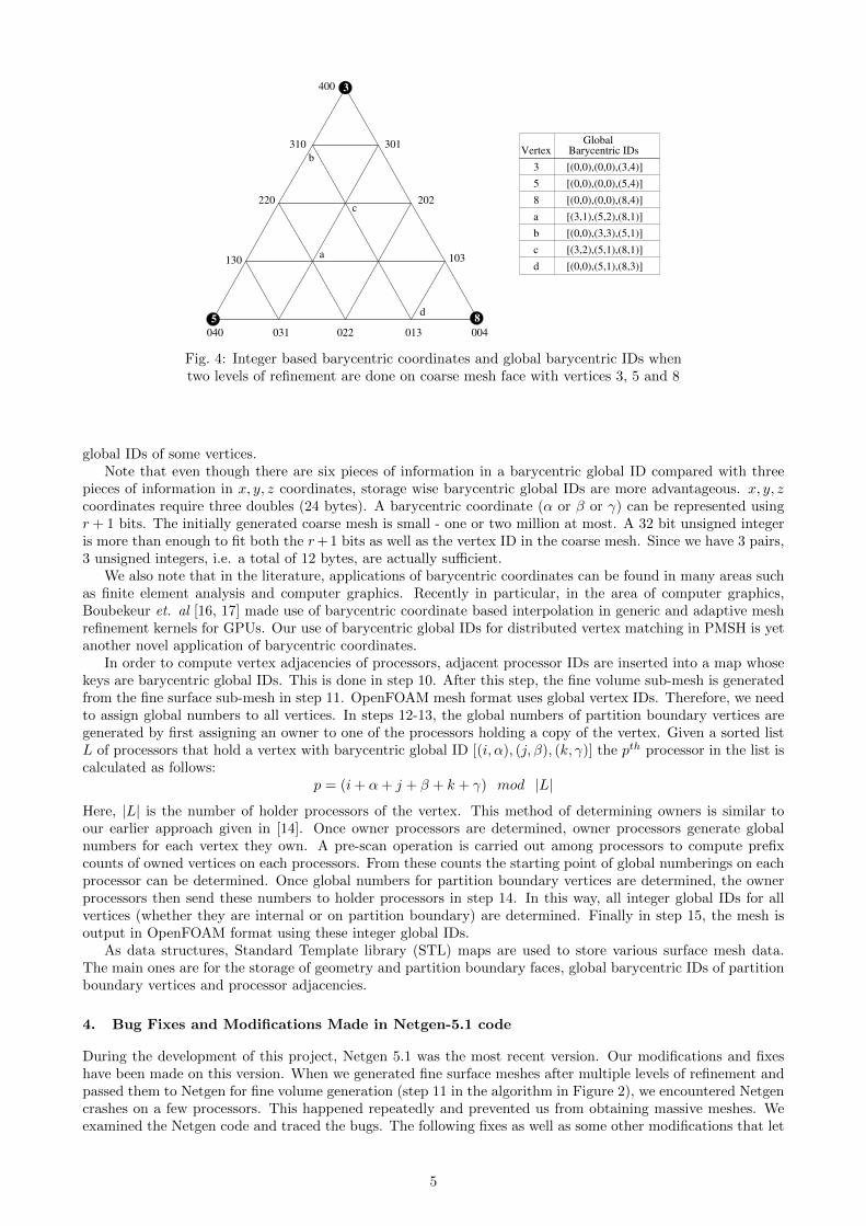
The new vertex identification system we came up with makes use of integer barycentric coordinates. Allprocessors know the IDs of the coarse mesh vertices. Hence, given a coarse surface mesh face that is definedwith vertices having indices i, j and k, the address of this face can be easily identified by employing a map thatmaps the key (i, j, k) to the corresponding local face address on each processor. However, when new faces andvertices are created as a result of refinement, their orders of creation are different on each processor. Therecan be different connectivity types as shown in Figure 3. Vertex connectivity is easy to resolve since the vertexconnectivities of partitions can be established by the coarse mesh vertices which are known by all processors.The newly created vertices on edges and faces introduce complications because their orders of creation aredifferent. Integer based barycentric coordinates help us to address all three types of connectivities and identifyall types of vertices (coarse or newly created) by a single mechanism. We define barycentric global IDs as asorted sequence of three (vertex id, integer barycentric coordinate) pairs, i.e., as [(i, α), (j, β), (k, γ)]. Here,i, j, k are either 0 or indices of vertices from ∂T v satisfying i < j < k and α, β, and γ are integer barycentriccoordinates with α + β + γ = 2r. Figure 4 shows an example of face defined by coarse mesh vertices 3, 5 and8 and the newly created vertices as a result of 2-level refinement. The table in Figure 4 shows the barycentric
4
d
b
202
301
400
310
220
130
040 031 022 013 004
103a
c
b
5 8
Barycentric IDsGlobal
Vertex
[(0,0),(0,0),(3,4)]
[(0,0),(0,0),(5,4)]
[(0,0),(0,0),(8,4)]
[(3,1),(5,2),(8,1)]
[(3,2),(5,1),(8,1)]
[(0,0),(3,3),(5,1)]
[(0,0),(5,1),(8,3)]
3
5
8
a
d
c
3
Fig. 4: Integer based barycentric coordinates and global barycentric IDs whentwo levels of refinement are done on coarse mesh face with vertices 3, 5 and 8
global IDs of some vertices.Note that even though there are six pieces of information in a barycentric global ID compared with three
pieces of information in x, y, z coordinates, storage wise barycentric global IDs are more advantageous. x, y, zcoordinates require three doubles (24 bytes). A barycentric coordinate (α or β or γ) can be represented usingr + 1 bits. The initially generated coarse mesh is small - one or two million at most. A 32 bit unsigned integeris more than enough to fit both the r+1 bits as well as the vertex ID in the coarse mesh. Since we have 3 pairs,3 unsigned integers, i.e. a total of 12 bytes, are actually sufficient.
We also note that in the literature, applications of barycentric coordinates can be found in many areas suchas finite element analysis and computer graphics. Recently in particular, in the area of computer graphics,Boubekeur et. al [16, 17] made use of barycentric coordinate based interpolation in generic and adaptive meshrefinement kernels for GPUs. Our use of barycentric global IDs for distributed vertex matching in PMSH is yetanother novel application of barycentric coordinates.
In order to compute vertex adjacencies of processors, adjacent processor IDs are inserted into a map whosekeys are barycentric global IDs. This is done in step 10. After this step, the fine volume sub-mesh is generatedfrom the fine surface sub-mesh in step 11. OpenFOAM mesh format uses global vertex IDs. Therefore, we needto assign global numbers to all vertices. In steps 12-13, the global numbers of partition boundary vertices aregenerated by first assigning an owner to one of the processors holding a copy of the vertex. Given a sorted listL of processors that hold a vertex with barycentric global ID [(i, α), (j, β), (k, γ)] the pth processor in the list iscalculated as follows:
p = (i+ α+ j + β + k + γ) mod |L|
Here, |L| is the number of holder processors of the vertex. This method of determining owners is similar toour earlier approach given in [14]. Once owner processors are determined, owner processors generate globalnumbers for each vertex they own. A pre-scan operation is carried out among processors to compute prefixcounts of owned vertices on each processors. From these counts the starting point of global numberings on eachprocessor can be determined. Once global numbers for partition boundary vertices are determined, the ownerprocessors then send these numbers to holder processors in step 14. In this way, all integer global IDs for allvertices (whether they are internal or on partition boundary) are determined. Finally in step 15, the mesh isoutput in OpenFOAM format using these integer global IDs.
As data structures, Standard Template library (STL) maps are used to store various surface mesh data.The main ones are for the storage of geometry and partition boundary faces, global barycentric IDs of partitionboundary vertices and processor adjacencies.
4. Bug Fixes and Modifications Made in Netgen-5.1 code
During the development of this project, Netgen 5.1 was the most recent version. Our modifications and fixeshave been made on this version. When we generated fine surface meshes after multiple levels of refinement andpassed them to Netgen for fine volume generation (step 11 in the algorithm in Figure 2), we encountered Netgencrashes on a few processors. This happened repeatedly and prevented us from obtaining massive meshes. Weexamined the Netgen code and traced the bugs. The following fixes as well as some other modifications that let
5

us access some functions within Netgen were made to the Netgen 5.1 code.
1. In libsrc/meshing/adfront3.cpp, points.Get(i).Valid() was changed to points[pi].Valid(). InNetgen-4, the loop index was defined as i, but after the loop index was changed to pi in Netgen-5.1, thiscode was not modified and could cause a segmentation fault in some cases.
2. In libsrc/meshing/improve3.cpp, on line 1236, suroundpts[l] = suroundpts[l-1] was added. Insome cases, if the if-clause below this line is not triggered, some elements of the suroundpts array may beundefined, which results in Netgen trying to reach a point with a garbage value. This fix avoids this.
3. In libsrc/interface/nginterface.cpp, we have added two functions, Ng_GetElement_Faces and writeOF,which allow us to get the faces and write the mesh in OpenFOAM format using Netgen’s nglib library.
The modifications enabled our tests to run successfully. Afterwards, we were able to generate multi-billionelement meshes. The bugs we discovered were also reported to the Netgen developer.
5. Tests and Results
We have meshed Onera M6 wing, sphere and shaft geometries shown in Figure 5 on NTNU’s Vilje system. Viljeis an SGI Altix ICE X system that has 936 nodes available to academic users. Each node has 2 Intel XeonE5-2670 (Sandy Bridge) processors with a total of 16 cores and 28 GB of memory. Table 2 shows the results ofthe mesh generation tests we have performed. On Vilje, due to restrictions, a job can be allocated at most 14.3TB total memory on up to 512 nodes. Therefore, we submitted tests that would satisfy this memory limit. Ifthis limit was higher, we would have been able to run our tests on higher numbers of cores and generate evenbigger meshes than what is shown in Table 2.
Fig. 5: Test geometries and meshes used: onera-m6.stl (a), sphere.geo (b) and shaft.geo (c). The top picture isthe coarse mesh and the bottom one is the (one-level refined) fine mesh
The columns Time taken by coarse mesh T and fine mesh T ′′ show the timings of steps 3-4 and steps 5-14respectively. Total timing is the summation of these two timings. Geometry input and mesh output are notincluded in the timings. Note that coarse mesh T is the initial mesh generated on each processor whereas finemesh T ′′ is the global mesh over all processors (i.e. union of all ∂Ti′′ ).
When looking at sequential mesh generation times of the coarse mesh, we see that on average 0.23 millionelements/minute rate is achieved by Netgen. In [3], Lohner states “Typical speeds for the complete generationof a mesh (surface, mesh, improvement) on current Intel Xeon chips with 3.2 GHz and sufficient memory areof the order of 0.5-2.0 million elements / minute.”. Netgen’s meshing rate on a single 2.6 GHz core is lowerthan this, but still it is a reasonable rate.
When looking at the parallel multi-billion element mesh generation results, we see that within the 1K-8Kcore range scalability is achieved. Figure 6 plots mesh generation time curves for (|T |, |T ′′|) pairs. |T | and |T ′′|are the sizes of initial coarse and the final fine mesh respectively. The inputs to our program are the followingparameters: (i) maximum element edge length in the mesh, (ii) mesh grading factor between 0.0 and 1.0, and(iii) number of levels of refinement. Parameters (i) − (ii) dictate the size of the coarse mesh and (i) − (iii)dictate the size of the final fine mesh. We can treat coarse and fine mesh sizes, i.e. the pair (|T |, |T ′′|) as our
6

Fig. 6: Parallel mesh generation timings ; for each geometry timingsobtained for ranges of (|T |, |T ′′|) pairs are drawn as separate curves
problem size. Since, when changing the number of cores (partitions), the submesh sizes can change (since anew mesh is generated), we have defined ranges on (|T |, |T ′′|) and plotted mesh generation times for ranges of(|T |, |T ′′|). Hence, given a roughly fixed problem size, i.e. a given range of the pair (|T |, |T ′′|), we see fromTable 2 that execution times decrease as the number of cores are increased. Of course, as the ratio |T ′′|/P getssmaller and smaller, any further increase in the number of cores will lead to smaller and smaller reductions inexecution time and will approach the time it takes to generate and partition the coarse mesh.
6. Discussion and Conclusions
We have developed a wrapper tool called PMSH around the existing sequential Netgen mesh generator thatenabled us to generate multi-billion element tetrahedral meshes for the OpenFOAM applications. The meshgeneration runs on 1K through 8K cores with 14.3 TB total memory limit show that our PMSH implemen-tation scales. Seven billion element meshes that were generated on 8K cores for the Onera M6 wing and thesphere geometries took about 21 minutes and 14 minutes respectively. With a sequential rate of 0.23 millionelements/minute, such a mesh would need roughly 21 days to be generated sequentially. It is also interestingto note that by choosing smaller initial coarse meshes, roughly billion element sized meshes can be generatedin 2-4 minutes.
The PMSH tool code is maintained at https://code.google.com/p/pmsh/. Our future work will focus on thedevelopment of a malleable parallel mesh generation system and implementation of more advanced schemes forprojecting vertices on geometric boundaries.
7

Acknowledgements
This work was financially supported by the PRACE-3IP project funded in part by the EUs 7th FrameworkProgramme (FP7/2012-2014) under grant agreement no. RI-312763. We thank Peter Stadelmeyer for initialdiscussions that motivated the development of this tool. We also acknowledge greatly Vilje supercomputerallocation provided to us by NTNU and the always prompt helps we received from Bjorn Lindi on the use ofVilje system. Finally, we thank Mustafa Dindar for providing us with Onera M6 wing geometry in STL format.
8

Table 2: Mesh generation results
Number Allocated Job Refinement Mesh Size (M) Time Taken by (s)Geometry of Cores Memory (TB) Levels (r) Coarse T Fine T ′′ Coarse T Fine T ′′ Total
oneram6.stl
1024 7.2 4 0.2 156.1 78.95 96.08 175.032048 14.3 4 0.2 174.8 78.93 95.38 174.314096 14.3 4 0.2 183.1 85.67 55.16 140.838192 14.3 4 0.2 189.6 81.97 51.27 133.241024 7.2 5 0.2 1014.7 78.96 715.3 794.262048 14.3 5 0.2 1114.3 78.89 521.68 600.574096 14.3 5 0.2 1123.3 82.73 316.04 398.778192 14.3 5 0.2 1152.7 82.14 152.66 234.81024 7.2 4 1.2 929.5 483.15 700.91 1184.062048 14.3 4 1.2 970.9 482.69 331.96 814.654096 14 4 1.2 909.1 537.04 202.96 7408192 14 4 1.2 1028.9 510.94 152.93 663.872048 14.3 5 1.2 7030.7 483.16 2719.29 3202.454096 14 5 1.2 6393.5 538 1831.23 2369.238192 14 5 1.2 7209.8 510.59 713.66 1224.25
sphere.geo
2048 14.3 5 0.3 1773.3 184.42 583.59 768.014096 14.3 5 0.3 2134.4 242.52 204.96 447.488192 14.3 5 0.3 2163.3 232.15 133.28 365.431024 7.2 5 0.3 1625.5 181.18 796.93 978.111024 7.2 4 0.2 146.7 43.88 69.72 113.62048 14.3 4 0.2 176.7 44.01 32.32 76.334096 14.3 4 0.2 198.7 47.02 23.6 70.628192 14.3 4 0.2 217 45.04 10.8 55.841024 7.2 5 0.2 1048.4 43.95 488.25 532.22048 14.3 5 0.2 1278.4 44.02 230.87 274.894096 14.3 5 0.2 1367.6 47 138.46 185.468192 14.3 5 0.2 1476.7 46.74 92.01 138.75
sphere.stl
1024 7.2 4 1.4 829.5 286.32 319.88 606.22048 14.3 4 1.4 931.4 286.96 201.49 488.454096 14.3 4 1.4 900.4 299.03 150.31 449.348192 14.3 4 1.4 1001.5 294.21 105.18 399.391024 7.2 4 0.4 296.4 94.13 114.04 208.172048 14.3 4 0.4 301.6 93.81 69.17 162.984096 14.3 4 0.4 365.4 97.91 45.35 143.268192 14.3 4 0.4 417.4 96.31 40.41 136.721024 7.2 5 1.4 6392.3 286.51 2938.7 3225.212048 14.3 5 1.4 6847.5 286.88 2212.16 2499.044096 14.3 5 1.4 6283.1 298.83 912.7 1211.538192 14.3 5 1.4 7053.6 293.56 513.41 806.971024 7.2 5 0.4 2120 94 924.97 1018.972048 14.3 5 0.4 2131.1 93.76 525.56 619.324096 14.3 5 0.4 2584.5 97.82 287.31 385.138192 14.3 5 0.4 2840.7 96.59 166.04 262.63
shaft.geo
1024 7.2 4 0.2 139.6 37.37 52.55 89.922048 14.3 4 0.2 166.8 37.4 28.61 66.014096 14.3 4 0.2 182.5 39.01 22.11 61.128192 14.3 4 0.2 221.4 38.42 25.73 64.151024 7.2 4 0.4 281.4 75.21 110.85 186.062048 14.3 4 0.4 295.6 75.7 55.71 131.414096 14.3 4 0.4 351.7 78.87 40.67 119.548192 14.3 4 0.4 382.2 77.74 36.23 113.971024 7.2 5 0.2 948.4 37.38 515.95 553.332048 14.3 5 0.2 1139.9 37.47 221.87 259.344096 14.3 5 0.2 1191.5 39 125.79 164.798192 14.3 5 0.2 1340.3 38.42 82.55 120.971024 7.2 5 0.4 1991.3 75.21 920.31 995.522048 14.3 5 0.4 2081.9 75.37 486.93 562.34096 14.3 5 0.4 2475.1 78.81 260.88 339.698192 14.3 5 0.4 2568.2 77.84 168.31 246.15
9

References
1. OpenFoam. http://www.openfoam.org/.
2. J. Schoberl. Netgen an advancing front 2d/3d-mesh generator based on abstract rules. Computing andvisualization in science, 1(1):41–52, 1997.
3. Rainald Lohner. Recent advances in parallel advancing front grid generation. Archives of ComputationalMethods in Engineering, pages 1–14, 2014.
4. J. Bell L Chacon R. Falgout M. Heroux P. Hovland E. Ng C Webster S. Wild J. Dongarra, J Hittinger.Applied mathematics research for exascale computing report.
5. WN Dawes, SA Harvey, Simon Fellows, Neil Eccles, D Jaeggi, and WP Kellar. A practical demonstrationof scalable, parallel mesh generation. In 47th AIAA Aerospace Sciences Meeting & Exhibit, pages 5–8,2009.
6. A. Chernikov F. Blagojevic and D. Nikolopoulos. A multigrain delaunay mesh generation method formulticore smt-based architectures. Journal of Parallel and Distributed Systems, 69(7):589–600, 2009.
7. D3D mesh generator. http://mech.fsv.cvut.cz/~dr/d3d.html.
8. MeshSim, Simmetrix inc. http://www.simmetrix.com.
9. E Ivanov, O Gluchshenko, H Andra, and A Kudryavtsev. Parallel software tool for decomposing andmeshing of 3d structures. 2007.
10. Pamgen Mesh Generation. http://trilinos.sandia.gov/packages/pamgen/, 2014.
11. M. Vazquez G. Houzeaux, R. de la Cruz. Parallel uniform mesh subdivision in alya. PRACE project(FP7/2007-2013), 2011.
12. P. Kabelikova, A. Ronovsky, and V. Vondrak. Parallel mesh multiplication for code saturne. PRACEproject (FP7/2007-2013), 2011.
13. V. Vondrak C. Moulinec A. Ronovsky, P. Kabelikova. Parallel mesh multiplication and its implementa-tion in code saturne. In Proc. of the Third International Conference on Parallel, Distributed, Grid andCloud Computing for Engineers. Civil-Comp Press, 2013.
14. Y. Yilmaz, C. Ozturan, O. Tosun, A. H. Ozer, and S. Soner. Parallel mesh generation, migration andpartitioning for the elmer application. PRACE project (FP7/2007-2013), 2011.
15. G. Karypis and V. Kumar. A fast and high quality multilevel scheme for partitioning irregular graphs.SIAM Journal on scientific Computing, 20(1):359–392, 1998.
16. T. Boubekeur and C. Schlick. Generic mesh refinement on gpu. In Proceedings of the ACM SIG-GRAPH/EUROGRAPHICS conference on Graphics hardware, pages 99–104. ACM, 2005.
17. T. Boubekeur and C. Schlick. A flexible kernel for adaptive mesh refinement on gpu. In ComputerGraphics Forum, volume 27, pages 102–113. Wiley Online Library, 2008.
10