geomax zone20 h user manual - new england laser
TRANSCRIPT
GeoMax Zone20 H
User Manual
Version 1.0English
Zone20 H | 2Introduction
IntroductionPurchase Congratulations on the purchase of a GeoMax Rotating Laser product.
This manual contains important safety directions as well as instructions for setting up the product and operating it. Refer to "1 Safety Directions" for further information.Read carefully through the User Manual before you switch on the product.
Product Identification The type and serial number of your product are indicated on the type plate.Always refer to this information when you need to contact your agency or GeoMax authorised service work-shop.
Validity of this manual This manual applies to the Zone20 H lasers. Differences between the models are marked and described.
Availabledocumentation
Refer to the following resources for all Zone20 H documentation/software:• the GeoMax Zone20 H CD• the GeoMax website: http://www.geomax-positioning.com
Name Description/Format
Zone20 H Quick Guide
Provides an overview of the product. Intended as a quick reference guide.
Zone20 H User Manual
All instructions required in order to operate the product to a basic level are contained in the User Manual. Provides an overview of the product together with technical data and safety directions.
-

Table of Contents Zone20 H | 3
Table of ContentsIn this manual Chapter Page
1 Safety Directions 41.1 General 41.2 Definition of Use 41.3 Limits of Use 51.4 Responsibilities 51.5 Hazards of Use 51.6 Laser Classification 6
1.6.1 General 61.6.2 Zone20 H 7
1.7 Electromagnetic Compatibility EMC 71.8 FCC Statement, Applicable in U.S. 8
2 Description of the System 102.1 System Components 102.2 Zone20 H Laser Components 102.3 Case Components 112.4 Setup 11
3 Operation 123.1 Buttons 123.2 LED Indicators 123.3 Turning the Zone20 H on and off 133.4 Automatic Mode 133.5 Manual Mode 133.6 Elevation Alert (H.I.) Function 14
4 Receivers 154.1 ZRB35 Receiver 154.2 ZRP105 Receiver 164.3 ZRD105, Digital Receiver 17
5 Applications 195.1 Setting Forms 195.2 Checking Grades 195.3 Manual Grades 20
6 Batteries 216.1 Operating Principles 216.2 Battery for Zone20 H 21
7 Accuracy Adjustment 247.1 Checking the Level Accuracy 247.2 Adjusting the Level Accuracy 24
8 Troubleshooting 26
9 Care and Transport 289.1 Transport 289.2 Storage 289.3 Cleaning and Drying 28
10 Technical Data 2910.1 Conformity to National Regulations 2910.2 Dangerous Goods Regulations 2910.3 General Technical Data of the Laser 29

Zone20 H | 4Safety Directions
1 Safety Directions1.1 General
Description The following directions enable the person responsible for the product, and the person who actually uses the equipment, to anticipate and avoid operational hazards.
The person responsible for the product must ensure that all users understand these directions and adhere to them.
About Warning Messages
Warning messages are an essential part of the safety concept of the instrument. They appear wherever hazards or hazardous situations can occur.
Warning messages...• make the user alert about direct and indirect hazards concerning the use of the product.• contain general rules of behaviour.
For the users‘ safety, all safety instructions and safety messages shall be strictly observed and followed! Therefore, the manual must always be available to all persons performing any tasks described herein.
DANGER, WARNING, CAUTION and NOTICE are standardized signal words for identifying levels of hazards and risks related to personal injury and property damage. For your safety it is important to read and fully understand the table below with the different signal words and their definitions! Supplementary safety information symbols may be placed within a warning message as well as supplementary text.
1.2 Definition of Use
Intended use • The product casts a horizontal laser plane or a laser beam for the purpose of alignment.• The laser beam can be detected by means of a laser detector.• Remote control of product.• Data communication with external appliances.
Reasonably foreseeable misuse
• Use of the product without instruction.• Use outside of the intended use and limits.• Disabling safety systems.• Removal of hazard notices.• Opening the product using tools, for example screwdriver, unless this is permitted for certain functions.• Modification or conversion of the product.• Use after misappropriation.• Use of products with obvious damages or defects.• Use with accessories from other manufacturers without the prior explicit approval of GeoMax.• Inadequate safeguards at the working site.• Deliberate dazzling of third parties.• Controlling of machines, moving objects or similar monitoring application without additional control
and safety installations.
Type Description
� DANGER Indicates an imminently hazardous situation which, if not avoided, will result in death or serious injury.
� WARNING Indicates a potentially hazardous situation or an unintended use which, if not avoided, could result in death or serious injury.
� CAUTION Indicates a potentially hazardous situation or an unintended use which, if not avoided, may result in minor or moderate injury.
NOTICE Indicates a potentially hazardous situation or an unintended use which, if not avoided, may result in appreciable material, financial and environmental damage.
Important paragraphs which must be adhered to in practice as they enable the product to be used in a technically correct and efficient manner.

Safety Directions Zone20 H | 5
1.3 Limits of Use
Environment Suitable for use in an atmosphere appropriate for permanent human habitation: not suitable for use in aggressive or explosive environments.
� DANGER Local safety authorities and safety experts must be contacted before working in hazardous areas, or close to electrical installations or similar situations by the person in charge of the product.
1.4 Responsibilities
Manufacturer of the product
GeoMax AG, CH-9443 Widnau, hereinafter referred to as GeoMax, is responsible for supplying the product, including the user manual and original accessories, in a safe condition.
Person responsible for the product
The person responsible for the product has the following duties:• To understand the safety instructions on the product and the instructions in the user manual.• To ensure that it is used in accordance with the instructions.• To be familiar with local regulations relating to safety and accident prevention.• To inform GeoMax immediately if the product and the application becomes unsafe.• To ensure that the national laws, regulations and conditions for the operation of e.g. radio transmitters
or lasers are respected.
1.5 Hazards of Use
� CAUTION Watch out for erroneous measurement results if the product has been dropped or has been misused, modi-fied, stored for long periods or transported.Precautions:Periodically carry out test measurements and perform the field adjustments indicated in the user manual, particularly after the product has been subjected to abnormal use as well as before and after important measurements.
� DANGER Because of the risk of electrocution, it is dangerous to use poles, levelling staffs and extensions in the vicinity of electrical installations such as power cables or electrical railways.Precautions:Keep at a safe distance from electrical installations. If it is essential to work in this environment, first contact the safety authorities responsible for the electrical installations and follow their instructions.
NOTICE With the remote control of products, it is possible that extraneous targets will be picked out and measured.Precautions:When measuring in remote control mode, always check your results for plausibility.
� WARNING If the product is used with accessories, for example masts, staffs, poles, you may increase the risk of being struck by lightning.Precautions:Do not use the product in a thunderstorm.
� WARNING Inadequate securing of the working site can lead to dangerous situations, for example in traffic, on building sites and at industrial installations.Precautions:Always ensure that the working site is adequately secured. Adhere to the regulations governing safety, accident prevention and road traffic.
� CAUTION If the accessories used with the product are not properly secured and the product is subjected to mechan-ical shock, for example blows or falling, the product may be damaged or people can sustain injury.Precautions:When setting-up the product, make sure that the accessories are correctly adapted, fitted, secured, and locked in position.Avoid subjecting the product to mechanical stress.

Zone20 H | 6Safety Directions
� CAUTION During the transport, shipping or disposal of batteries it is possible for inappropriate mechanical influences to constitute a fire hazard.Precautions:Before shipping the product or disposing of it, discharge the batteries by running the product until they are flat.When transporting or shipping batteries, the person in charge of the product must ensure that the appli-cable national and international rules and regulations are observed. Before transportation or shipping contact your local passenger or freight transport company.
� WARNING During dynamic applications, for example stakeout procedures there is a danger of accidents occurring if the user does not pay attention to the environmental conditions around, for example obstacles, excava-tions or traffic.Precautions:The person responsible for the product must make all users fully aware of the existing dangers.
� WARNING If you open the product, either of the following actions may cause you to receive an electric shock.• Touching live components• Using the product after incorrect attempts were made to carry out repairsPrecautions:Do not open the product. Only GeoMax authorised service workshops are entitled to repair these products.
� WARNING If the product is improperly disposed of, the following can happen:• If polymer parts are burnt, poisonous gases are produced which may impair health.• If batteries are damaged or are heated strongly, they can explode and cause poisoning, burning, corro-
sion or environmental contamination.• By disposing of the product irresponsibly you may enable unauthorised persons to use it in contraven-
tion of the regulations, exposing themselves and third parties to the risk of severe injury and rendering the environment liable to contamination.
Precautions:
Product-specific treatment and waste management information can be downloaded from the GeoMax website at http://www.geomax-positioning.com/treatment or received from your GeoMax distributor.
� WARNING Only GeoMax authorised service workshops are entitled to repair these products.
� WARNING High mechanical stress, high ambient temperatures or immersion into fluids can cause leakage, fire or explosions of the batteries.Precautions:Protect the batteries from mechanical influences and high ambient temperatures. Do not drop or immerse batteries into fluids.
� WARNING If battery terminals are short circuited e.g. by coming in contact with jewellery, keys, metalized paper or other metals, the battery can overheat and cause injury or fire, for example by storing or transporting in pockets.Precautions:Make sure that the battery terminals do not come into contact with metallic objects.
The product must not be disposed with household waste.Dispose of the product appropriately in accordance with the national regulations in force in your country.Always prevent access to the product by unauthorised personnel.

Safety Directions Zone20 H | 7
1.6 Laser Classification1.6.1 General
General The following chapters provide instructions and training information about laser safety according to inter-national standard IEC 60825-1 (2014-05) and technical report IEC TR 60825-14 (2004-02). The informa-tion enables the person responsible for the product and the person who actually uses the equipment, to anticipate and avoid operational hazards.
1.6.2 Zone20 H
General The rotating laser built into the product produces a visible laser beam which emerges from the rotating head.
The laser product described in this section is classified as laser class 1 in accordance with:• IEC 60825-1 (2014-05): "Safety of laser products"
These products are safe for momentary exposures but can be hazardous for deliberate staring into the beam. The beam may cause dazzle, flash-blindness and after-images, particularly under low ambient light conditions.Zone20 H:
Labelling
a) Laser beam
According to IEC TR 60825-14 (2004-02), products classified as laser class 1, class 2 and class 3R do not require:
• laser safety officer involvement,• protective clothes and eyewear,• special warning signs in the laser working area
if used and operated as defined in this User Manual due to the low eye hazard level.
National laws and local regulations could impose more stringent instructions for the safe use of lasers than IEC 60825-1 (2014-05) and IEC TR 60825-14 (2004-02).
Description Value
Maximum average radiant output power 2.6 mW
Pulse duration (effective) 1.1 ms
Pulse repetition frequency 10 Hz
Beam divergence 0.2 mrad
Wavelength 635 nm
011245_001
aa

Zone20 H | 8Safety Directions
1.7 Electromagnetic Compatibility EMC
Description The term Electromagnetic Compatibility is taken to mean the capability of the product to function smoothly in an environment where electromagnetic radiation and electrostatic discharges are present, and without causing electromagnetic disturbances to other equipment.
� WARNING Electromagnetic radiation can cause disturbances in other equipment.
Although the product meets the strict regulations and standards which are in force in this respect, GeoMax cannot completely exclude the possibility that other equipment may be disturbed.
� CAUTION There is a risk that disturbances may be caused in other equipment if the product is used with accessories from other manufacturers, for example field computers, personal computers or other electronic equip-ment, non-standard cables or external batteries.Precautions:Use only the equipment and accessories recommended by GeoMax. When combined with the product, they meet the strict requirements stipulated by the guidelines and standards. When using computers or other electronic equipment, pay attention to the information about electromagnetic compatibility provided by the manufacturer.
� CAUTION Disturbances caused by electromagnetic radiation can result in erroneous measurements.Although the product meets the strict regulations and standards which are in force in this respect, GeoMax cannot completely exclude the possibility that the product may be disturbed by intense electromagnetic radiation, for example, near radio transmitters, two-way radios or diesel generators.Precautions:Check the plausibility of results obtained under these conditions.
� CAUTION If the product is operated with connecting cables attached at only one of their two ends, for example external supply cables, interface cables, the permitted level of electromagnetic radiation may be exceeded and the correct functioning of other products may be impaired. Precautions:While the product is in use, connecting cables, for example product to external battery, product to computer, must be connected at both ends.
Radios or Digital Cellular Phones
Use of product with radio or digital cellular phone devices:
� WARNING Electromagnetic fields can cause disturbances in other equipment, in installations, in medical devices, for example pacemakers or hearing aids and in aircraft. It can also affect humans and animals.Precautions:Although the product meets the strict regulations and standards which are in force in this respect, GeoMax cannot completely exclude the possibility that other equipment can be disturbed or that humans or animals can be affected.
• Do not operate the product with radio or digital cellular phone devices in the vicinity of filling stations or chemical installations, or in other areas where an explosion hazard exists.
• Do not operate the product with radio or digital cellular phone devices near to medical equipment.• Do not operate the product with radio or digital cellular phone devices in aircraft.
1.8 FCC Statement, Applicable in U.S.
� WARNING This equipment has been tested and found to comply with the limits for a Class B digital device, pursuant to part 15 of the FCC rules.These limits are designed to provide reasonable protection against harmful interference in a residential installation.This equipment generates, uses and can radiate radio frequency energy and, if not installed and used in accordance with the instructions, may cause harmful interference to radio communications. However, there is no guarantee that interference will not occur in a particular installation.If this equipment does cause harmful interference to radio or television reception, which can be deter-mined by turning the equipment off and on, the user is encouraged to try to correct the interference by one or more of the following measures:• Reorient or relocate the receiving antenna.• Increase the separation between the equipment and the receiver.• Connect the equipment into an outlet on a circuit different from that to which the receiver is connected.• Consult the dealer or an experienced radio/TV technician for help.

Safety Directions Zone20 H | 9
� WARNING Changes or modifications not expressly approved by GeoMax for compliance could void the user's authority to operate the equipment.
Labelling Zone20 H
Labelling receiver
Labelling receiver
Labelling receiver
GeoMax AGCH-9443 Widnau
Complies with FDA performance standards forlaser products except for deviations pursuant to
Laser Notice Nr. 50 July 24, 2007
This device complies with part 15 of the FCCRules. Operation is subject to the following
two conditions: (1) This device may notcause harmful interference, and (2) This
device must accept any interferencereceived, including interference that
may cause undesired operation.
Serial Number: YWWY20H
Y W W Y 8 7 0 2 5 0 0
Class 1 Laser - IEC 60825-1:2014
Type: Zone20 H Power: 8.4V / 0.5A / Art.No.: 835251Made in China / Manufactured: MM/YYYY
011246_001
ZRB35:
This device complies with part 15 of the FCC Rules.Operation is subject to the following two conditions:(1) This device may not cause harmful interference,and (2) This device must accept any interferencereceived, including interference that may causeundesired operation.
Type: ZRB35Art.No.: 835246Power: 9V / 0.2AGeoMax AGCH-9443 WidnauMade in ChinaManufactured: MM/YYYYS.No.: 1234567
011178_001
ZRP105:
This device complies with part 15 of the FCC Rules.Operation is subject to the following two conditions:(1) This device may not cause harmful interference, and(2) This device must accept any interference received, including interference that may cause undesired operation.
GeoMax AGCH-9443 Widnau
Type: ZRP105Art.No.: 835247Power: 3V / 60mAMade in ChinaManufactured: MM/YYYYS.No.: 1234567
011177_001
ZRD105:
This device complies with part 15 of the FCC Rules.Operation is subject to the following two conditions:(1) This device may not cause harmful interference, and(2) This device must accept any interference received, including interference that may cause undesired operation.
GeoMax AGCH-9443 Widnau
Type: ZRD105Art.No.: 835248Power: 3V / 60mAMade in ChinaManufactured: MM/YYYYS.No.: 1234567
011243_001

Zone20 H | 10Description of the System
2 Description of the System2.1 System Components
General description The Zone20 H is a laser tool for general construction and levelling applications such as• Setting forms• Checking grades• Controlling depths for excavationsIf set up within the self-levelling range, the Zone20 H automatically levels to create an accurate horizontal plane of laser light.Once the Zone20 H has levelled, the head will start rotating and the Zone20 H is ready for use. 30 seconds after the Zone20 H has completed the levelling, the H.I. Alert system becomes active and protects the Zone20 H against changes in elevation caused by movement of the tripod to ensure accurate work.
Available system components
The delivered components depend on the package ordered.
2.2 Zone20 H Laser Components
Zone20 H laser compo-nents
011247_001
ZBR35
Zone20 H
Li-Ion/Alkaline
ZDR105
ZPR105
a) Carry Handleb) LED Indicatorsc) Buttonsd) Battery compartmente) Charge LED (for Li-Ion battery pack)
011248_001
a
bc
d
e

Description of the System Zone20 H | 11
2.3 Case Components
Case components
2.4 Setup
Location • Keep the location clear of possible obstructions that could block or reflect the laser beam.• Place the Zone20 H on a stable ground. Ground vibration and extremely windy conditions can affect
the operation of the Zone20 H.• When working in a very dusty environment place the Zone20 H up-wind so the dirt is blown away from
the laser.
Setting up on a Tripod
• Attach the Zone20 H securely to a tripod or laser trailer, or mount on a stable level surface.• Always check the tripod or laser trailer before attaching the Zone20 H. Make sure all screws, bolts and
nuts are tight.• If a tripod has chains, they should be slightly loose to allow for thermal expansion during the day.• Secure the tripod on extremely windy days.
a) Zone20 H laserb) Charger (for Li-Ion versions only) c) Li-Ion battery pack or Alkaline battery packd) 4 x D-cell battery (for alkaline versions only)e) 2x AA-cell battery f) User Manual/CDg) Receiver mounted on the bracketh) Second receiver (can be purchased separately)
011249_001
a
bcd g
h e
f
Step Description
1. Set up the tripod.
2. Place the Zone20 H on the tripod.
3. Tighten the screw on the underside of the tripod to secure the Zone20 H on the tripod.
011250_001

Zone20 H | 12Operation
3 Operation3.1 Buttons
Buttons
Description of the Buttons
3.2 LED Indicators
Main Functions DescriptionThe LED Indicators have three main functions:• To indicate the level status of the axes.• To indicate the battery status.• To indicate an H.I. Alert condition.Diagram of the LED Indicators
Description of the LEDs
a) Up and Down Arrow buttonsb) Power buttonc) Automatic/Manual Mode button011251_001
ab
c
Button Function
Up and Down Arrow Press to enter a slope for an axis in Manual Mode.
Power Press to turn on or off the Zone20 H.
Automatic/Manual Mode
Press once to change the X-axis to Manual Mode with Y-axis self-levelling.
Press again to change the Y-axis to Manual Mode with X-axis self-levelling.
Press again to change both axes to Manual Mode with no self-levelling.
Press again to change back to Full Automatic Mode.
Note the changes in the LED indicators in the Manual Modes. The red LED indicates that the corresponding axis is in Manual Mode.
a) Low Battery Indicator LEDb) X-axis Indicator LEDc) Y-axis Indicator LED
011252 001
ab
c
IF the is/are THEN
Low Battery Indicator LED (Li-Ion & alkaline)
off the battery is okay.
on the battery is getting low.
X-axis and Y-axis Indicator LEDs
green the axis is level.
flashing green the axis is levelling.
red the axis is in Manual Mode.
both flashing red an H.I. Alert is indicated.

Operation Zone20 H | 13
3.3 Turning the Zone20 H on and off
Turning on and off Press the Power button to turn on or off the Zone20 H.After turning on: • If set up within the 5° self-levelling range, the Zone20 H automatically levels to create an accurate
horizontal plane of laser light.• Once levelled, the head starts rotating and Zone20 H is ready for use.• After 30 seconds of completing the levelling, the H.I. Alert system becomes active to protect the laser
against changes in elevation caused by movement or settling of the tripod.• The self-levelling system and H.I. Alert function continues to monitor the position of the laser beam to
ensure consistent and accurate work.
3.4 Automatic Mode
Description of the Auto-matic Mode
The Zone20 H always starts up in Automatic Mode.In Automatic Mode the Zone20 H automatically levels if set up within the 5° self-levelling range.
3.5 Manual Mode
Description of the Manual Mode
After start-up the Manual Mode can be activated. In Manual Mode the self-levelling will be deactivated. The following options are available:• Change the X-axis to Manual Mode• Change the Y-axis to Manual Mode• Change to Full Manual Mode
After turning the Zone20 H off and on again, the Zone20 H is in Automatic Mode.
Changing the X-axis to Manual Mode
After startup, press the Automatic/Manual Mode Button once to change the X-axis to Manual Mode.
The X-axis and Y-axis are marked on the top of the Zone20 H.
• The X-axis does not self-level and a slope can be entered in this axis using the Up and Down Arrow buttons on the Zone20 H.
• The X-axis LED is red.• The Y-axis continues to self-level and the Y-axis LED flashes
green until level.
When the X-axis is in Manual Mode, the X-axis can be sloped upwards or downwards as illustrated.
011300_001

Zone20 H | 14Operation
Changing the Y-axis to Manual Mode
Press the Automatic/Manual Mode button again to change the Y-axis to Manual Mode.
The X-axis and Y-axis are marked on the top of the Zone20 H.
Changing to Full Manual Mode
Press the Automatic/Manual Mode button again to change to Full Manual Mode.
The X and Y axes are marked on the top of the Zone20 H.
3.6 Elevation Alert (H.I.) Function
Description of the Eleva-tion Alert function
• The Elevation Alert or Height of Instrument (H.I.) function prevents incorrect work caused by move-ment or settling of the tripod that would cause the laser to level at a lower height.
• The Elevation Alert function becomes active and monitors the movement of the laser 30 second after the Zone20 H has completely levelled and the head of the laser starts rotating.
• The Elevation Alert monitors the laser. If disturbed, both the X-axis LED and Y-axis LED flash and the Zone20 H beeps rapidly.
• To stop the alert turn Zone20 H off and on again. Check the height of the laser before beginning to work again.
The Elevation Alert function turns on automatically every time the Zone20 H is turned on.
Disable or enable the Elevation Alert function
The Elevation Alert function can be disabled or enabled by pressing the following button combination: • With the Zone20 H turned on, press and hold the Up and Down Arrow buttons.• Press the Automatic/Manual Mode button.
The Zone20 H beeps once to indicate the change.
• The Y-axis does not self-level and a slope can be entered in this axis using the Up and Down Arrow buttons on the Zone20 H.
• The Y-axis LED is red.• The X-axis continues to self-level and the X-axis LED flashes
green until level.
When the Y-axis is in Manual Mode, the Y-axis can be sloped upwards or downwards as illustrated.
005789_001
• Both the X-axis and Y-axis do not self-level and a slope can be entered in the Y-axis using the Up and Down Arrow buttons on the Zone20 H.
• The X-axis LED is red.• The Y-axis LED is red.
When both the X-axis and Y-axis are in Manual Mode, the Y-axis can be sloped using the Up and Down Arrow buttons.
011302_001

Receivers Zone20 H | 15
4 Receivers
Description The Zone20 H is sold with the ZRB35, ZRP105 or ZRD105 Receiver.
4.1 ZRB35 Receiver
Instrument components part 1 of 2
Instrument components part 2 of 2
Description of the buttons
a) Level vialb) Keypadc) On-graded) Laser Reception windowe) LCD windowf) Audio Speaker
Component Description
Level vial Aids to keep the rod plumb when taking readings.
Keypad Power, accuracy and volume functions.
On-grade Indicates the on-grade position of the laser.
Laser Reception window
Detects the laser beam. The reception windows must be directed towards the laser.
LCD window Front and rear LCD arrow indicate the detector’s position.
Audio Speaker Indicates the detector’s position:• High - Fast beeping• On-grade - Solid tone• Low - Slow beeping
011190_001
a
b
c
def
a) Bracket Mounting Holeb) Offset notchc) Battery doord) Serial number labele) Product label
Component Description
Bracket Mounting Hole
Location to attach the receiver bracket for normal operation.
Offset notch Use to transfer reference marks. The notch is 45 mm (1.75") below to top of the detector.
Battery door Access to the battery compartment.
005666_001
a
b
c
de
a) Audiob) Bandwidthc) Power
Button Function
Audio Press to change the audio output.
Bandwidth Press to change detection bandwidth.
Power Press once to turn on the Receiver.
011192_001
ab
c

Zone20 H | 16Receivers
4.2 ZRP105 Receiver
Instrument components part 1 of 2
Instrument components part 2 of 2
a) Level vialb) Audio Speakerc) LCD windowd) LEDse) Laser Reception windowf) On-gradeg) Keypad
Component Description
Level vial Aids to keep the rod plumb when taking readings.
Audio Speaker Indicates the detector’s position:• High - Fast beeping• On-grade - Solid tone• Low - Slow beeping
LCD window Front and rear LCD arrow indicate the detector’s position.
LEDs Display the relative position of the laser beam. Three channel indication:• High - Red• On-grade - Green• Low - Blue
Laser Reception window
Detects the laser beam. The reception windows must be directed towards the laser.
On-grade Indicates the on-grade position of the laser.
Keypad Power, accuracy and volume functions.
011193_001
abc
d
ef
g
a) Bracket Mounting Holeb) Offset notchc) Product labeld) Battery door
Component Description
Bracket Mounting Hole
Location to attach the receiver bracket for normal operation.
Offset notch Use to transfer reference marks. The notch is 85 mm (3.35") below to top of the detector.
Product label The serial number is located inside the battery compartment.
Battery door Access to the battery compartment.
011194_001
a
b
c
d

Receivers Zone20 H | 17
Description of the Buttons
Menu access and navi-gation
To access the menu of the ZRP105 Receiver, press the Bandwidth button and Audio button simultaneously.• Use the Bandwidth button and Audio button to change parameters.• Use the Power button to scroll through the menu.
Menu MENU MODE - The blue LED will blink slowly indicating menu mode.
4.3 ZRD105, Digital Receiver
The ZRD105 Digital Receiver provides you with basic position information by using an arrow display plus digital readout.
Instrument components
Description of the Buttons
a) Powerb) Audioc) Bandwidth
Button Function
Power Press once to turn on the Receiver.
Audio Press to change the audio output.
Bandwidth Press to change detection bandwidth.
011195_001
a
b
c
Menu Function Indication
LED Changes the brightness of the LED indicators.
Red and green LEDs - High/Low/Off
Red and Green LEDs change brightness to indicate this parameter.
BAT Turns on or off the Laser low battery indication on the receiver.
Green LED is on: Laser low battery icon function is active.
The laser icon flashes to indi-cate this parameter.
Red LED is on: Laser low battery icon function is not active.
MEM Turns on or off the position memory function.
Green LED is on: function is on.
The down arrow bars are filling to indicate this param-eter.
Red LED is on: function is off.
a) Speakerb) LCD Digital Displayc) LED Displayd) Power buttone) Target buttonf) Reception windowg) Bandwidth buttonh) Audio button
011196_001
ab
cde
f
g
h
Button Function
Power Press once to turn on the receiver.
Press 1.5 seconds to turn off the receiver.
Target Press to capture the digital reading.
Bandwidth Press to change detection bandwidths.
Audio Press to change the audio output.

Zone20 H | 18Applications
5 Applications5.1 Setting Forms
Setting Forms step-by-step
Application shown using the ZRP105 Receiver.
5.2 Checking Grades
Checking Grades step-by-step
Application shown using the ZRP105 Receiver.
Step Description
1. Set up the Zone20 H on a tripod.
2. Set up the tripod on a stable surface outside the working area.
3. Attach the receiver to a rod.
4. Turn on the Zone20 H and the receiver.
5. Set the base of the rod on a known point for the finished height of forms.
6. Adjust the height of the receiver on the rod until the on-grade (centre-line) position is indicated on the receiver by:• the centre bar• the green flashing LED• a solid audio tone
7. Set the rod with the attached receiver on top of the form.
8. Adjust the height of the form until the on-grade position is again indicated.
9. Continue to additional positions until the forms are levelled to the rotating plane of the Zone20 H.
ba
4
011253_001
65
7
8
9
1 + 2
3
Step Description
1. Set up the Zone20 H on a tripod.
2. Set up the tripod on a stable surface outside the working area.
3. Attach the receiver to a rod.
4. Turn on the Zone20 H and the receiver.
5. Set the base of the rod on a known point for the finished grade.
6
ba
4
011254 001
3
1 + 2
5
7a
7b
7c
Applications Zone20 H | 19
5.3 Manual Grades
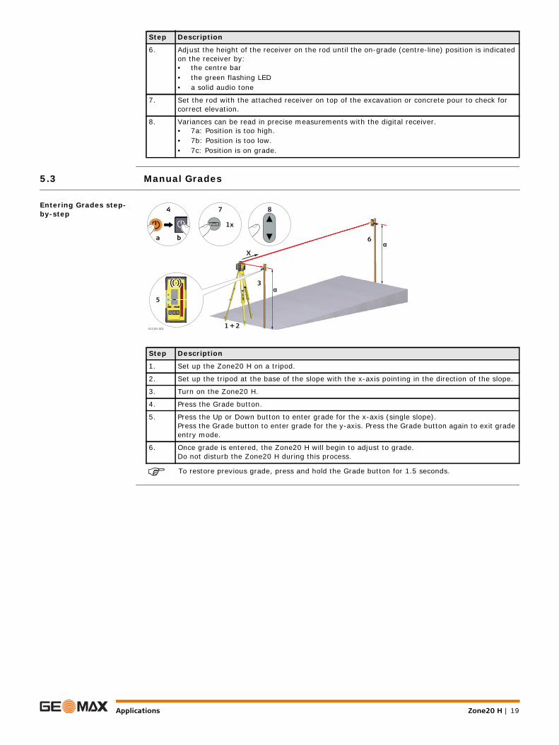
Entering Grades step-by-step
To restore previous grade, press and hold the Grade button for 1.5 seconds.
6. Adjust the height of the receiver on the rod until the on-grade (centre-line) position is indicated on the receiver by:• the centre bar• the green flashing LED• a solid audio tone
7. Set the rod with the attached receiver on top of the excavation or concrete pour to check for correct elevation.
8. Variances can be read in precise measurements with the digital receiver.• 7a: Position is too high.• 7b: Position is too low. • 7c: Position is on grade.
Step Description
Step Description
1. Set up the Zone20 H on a tripod.
2. Set up the tripod at the base of the slope with the x-axis pointing in the direction of the slope.
3. Turn on the Zone20 H.
4. Press the Grade button.
5. Press the Up or Down button to enter grade for the x-axis (single slope).Press the Grade button to enter grade for the y-axis. Press the Grade button again to exit grade entry mode.
6. Once grade is entered, the Zone20 H will begin to adjust to grade. Do not disturb the Zone20 H during this process.
1x
7 8
ba
4
011255_001
5
6
1 + 2
3
X
α
α

Zone20 H | 20Batteries
6 Batteries
Description The Zone20 H can be purchased with alkaline batteries or a rechargeable Li-Ion battery pack.The following information is appropriate only to the model you have purchased.
6.1 Operating Principles
First-time Use / Charging Batteries
• The battery must be charged prior to using it for the first time because it is delivered with an energy content as low as possible.
• The permissible temperature range for charging is between 0°C to +40°C/ +32°F to +104°F. For optimal charging, we recommend charging the batteries at a low ambient temperature of +10°C to +20°C/+50°F to +68°F if possible.
• It is normal for the battery to become warm during charging. Using the chargers recommended by GeoMax, it is not possible to charge the battery if the temperature is too high.
• For new batteries or batteries that have been stored for a long time (> three months), it is effectual to make only one charge/discharge cycle.
• For Li-Ion batteries, a single discharging and charging cycle is sufficient. We recommend carrying out the process when the battery capacity indicated on the charger or on a GeoMax product deviates signif-icantly from the actual battery capacity available.
Operation / Discharging • The batteries can be operated from -20°C to +55°C/-4°F to +131°F.• Low operating temperatures reduce the capacity that can be drawn; high operating temperatures
reduce the service life of the battery.
6.2 Battery for Zone20 H
Charging the Li-Ion battery pack step-by-step
The rechargeable Li-Ion battery pack on the Zone20 H can be charged without removing the battery pack from the laser.
The battery pack reaches a full charge in approximately 5 hours if completely empty. A one-hour charge should allow the Zone20 H to run for a full 8 hours.
Step Description
1. Slide the locking mechanism on the battery compartment to the centre position to expose the charge jack.
2. Plug the AC connector into the appropriate AC power source.
3. Connect the charger plug into the charge jack on the Zone20 H battery pack.
4. The small LED next to the charge jack flashes indicating that the Zone20 H is charging. The LED is on solid when the battery pack is fully charged.
5. When the battery pack is fully charged, disconnect the charger plug from the charge jack.
6. Slide the locking mechanism to the left to prevent dirt from getting into the charging jack.
4
011256_001
13
2
5
6

Batteries Zone20 H | 21
Changing the Li-Ion batteries step-by-step
With the rechargeable Li-Ion battery pack the battery indicator on the Zone20 H LCD display shows when the battery pack is low and needs to be charged.The charge indicator LED on the Li-Ion battery pack indicates when the pack is being charged (flashing slowly) or fully charged (on, not flashing).
Changing the alkaline batteries step-by-step
With alkaline batteries the battery indicator on the Zone20 H LCD display flashes when the batteries are low and need to be replaced. If no battery icon is shown, the batteries are okay.
Step Description
The batteries are inserted in the front of the laser.
The rechargeable battery pack can be recharged without being removed from the laser. Refer to " Charging the Li-Ion battery pack step-by-step" for further information.
1. Slide the locking mechanism on the battery compartment to the right and open the cover of the battery compartment.
2. To remove the batteries:Remove the batteries from the battery compartment.
To insert the batteries:Insert the batteries into the battery compartment.
3. Close the cover of the battery compartment and slide the locking mechanism to the left until it locks into position.
011257_001
1
2
3
Step Description
The batteries are inserted in the front of the laser.
1. Slide the locking mechanism on the battery compartment to the right and open the cover of the battery compartment.
2. To remove the batteries:Remove the batteries from the battery compartment.
To insert the batteries:Insert the batteries into the battery compartment, ensuring that the contacts are facing in the right direction.
The correct polarity is displayed on the battery holder.
3. Close the cover of the battery compartment and slide the locking mechanism to the left until it locks into position.
011258_001
1
2
3

Zone20 H | 22Accuracy Adjustment
7 Accuracy Adjustment
About • It is the responsibility of the user to follow operating instructions and to periodically check the accuracy of the laser and work as it progresses.
• The Zone20 H is adjusted to the defined accuracy specification at the factory. It is recommended to check the laser for accuracy upon receipt and periodically thereafter to ensure accuracy is maintained. If the laser requires adjustment, contact your nearest authorised service centre or adjust the laser using the procedures described in this chapter.
• Only enter the accuracy adjustment mode when you plan to change the accuracy. Accuracy adjust-ments should only be performed by a qualified individual that understands basic adjustment principles.
• It is recommended to perform this procedure with two people on a relatively flat surface.
7.1 Checking the Level Accuracy
Checking the level accu-racy step-by-step
The Zone20 H is within its accuracy specification if the four marks are within ± 1.5 mm (± 1/16") from the centre.
Step Description
1. Place the Zone20 H on a flat, level surface or tripod approximately 30 m (100 ft) from a wall.
2. Align the first axis so that it is square to a wall. Allow the Zone20 H to self-level completely (approximately 1 minute after the Zone20 H begins to rotate).
3. Mark the position of the beam.
4. Rotate the laser 180° and allow it to self-level.
5. Mark the opposite side of the first axis.
6. Align the second axis of the Zone20 H by rotating it 90° so that this axis is square to the wall. Allow the Zone20 H to self-level completely.
7. Mark the position of the beam.
8. Rotate the laser 180° and allow it to self-level.
9. Mark the opposite side of the second axis.
011292_001
30 m (100 ft)
30 m (100 ft)
X+
X—
011293_001
30 m (100 ft)
30 m (100 ft)
Y+
Y—

Accuracy Adjustment Zone20 H | 23
7.2 Adjusting the Level Accuracy
Description
Entering adjustment mode step-by-step
The following sequence of LED behaviour occurs:• The X-axis and the Y-axis LEDs flash alternately three times.• The X-axis LED flashes three times, then flashes slowly until level. When the Zone20 H is level, the X-
axis LED is on, but does not flash.• The Y-axis LED is off.
Adjusting the X-axis step-by-step
The following sequence of LED behaviour occurs:• The X-axis and the Y-axis LEDs flash alternately three times.• The Y-axis LED flashes three times, then flashes slowly until level. When the Zone20 H is level, the Y-
axis LED is on, but does not flash.• The X-axis LED is off.
Adjusting the Y-axis step-by-step
Exiting adjustment mode step-by-step
Press and hold the Automatic/Manual Mode button for 3 seconds to save and exit Adjustment Mode.The X-axis LED and Y-axis LED flash alternately three times, then the Zone20 H shuts off.
Pressing the Power button at any time while in Adjustment Mode will exit the mode without saving changes.
In Adjustment Mode the X-axis LED indicates changes to the X-axis.
The Y-axis LED indicates changes to the Y-axis
011294_001
X
011295_001
Y
Step Description
1. Turn off the power.
2. Press and hold both the Up and Down Arrow buttons.
3. Press the Power button. The active axis is the X-axis.
Step Description
1. Press the Up and Down Arrow buttons to increment the laser beam up and down. Each incre-ment is indicated by a flash of the X-axis LED and a beep from the audio indicator.
2. Continue to press the Up and Down Arrow buttons and monitor the spot until the Zone20 H is within its specified range.
Five steps are equal to 10 arc seconds of change, or approximately 1.5 mm at 30 m (1/16" at 100’).
3. Press the Automatic/Manual Mode button to switch to the Y-axis.
Step Description
1. Press the Up and Down Arrow buttons to increment the laser beam up and down. Each incre-ment is indicated by a flash of the Y-axis LED and a beep from the audio indicator.
2. Continue to press the Up and Down Arrow buttons and monitor the spot until the Zone20 H is within its specified range.
Five steps are equal to 10 arc seconds of change, or approximately 1.5 mm at 30 m (1/16" at 100’).
3. Press the Automatic/Manual Mode button to switch back to the X-axis if desired.

Zone20 H | 24Troubleshooting
8 Troubleshooting
Alerts
Troubleshooting
Alert Symptom Possible causes and solutions
Low Battery LED flashes red, or is on but not flashing.
The batteries are low. Replace the alkaline batteries or recharge the Li-Ion battery pack. Refer to "6 Batteries".
Elevation (H.I.) AlertThe LEDs flash quickly with an audio beep.
The Zone20 H has been bumped or tripod was moved. Turn off Zone20 H to stop alert check the height of the laser before beginning to work again. Allow Zone20 H to re-level and check the height of the laser.After two minutes in the alert condi-tion, the unit will shut off automati-cally.
Servo Limit AlertAll LEDs flash sequentially.
The Zone20 H is tipped too far to reach a level position. Re-level the Zone20 H within the 5 degree self-levelling range.This alert will also be displayed any time the unit is tipped more than 45° from level. After two minutes in the alert condition, the unit will shut off automatically.
5 Hz +
Problem Possible Cause(s) Suggested Solutions
The Zone20 H is working, but not self-levelling.
The Zone20 H is in Manual Mode. The Zone20 H must be in Automatic Mode to self-level. Set the Zone20 H to Automatic Mode by pressing the Automatic/Manual Mode button.– In Automatic Mode the X-axis LED
and the Y-axis LED flash green while levelling.
– In Manual Mode the X-axis LED and/or the Y-axis LED are red.
Zone20 H does not turn on.
The batteries are low or dead. Check the batteries and change or charge the batteries if necessary. If the problem continues, return the Zone20 H to an authorised service centre for service.
The distance of the laser is reduced.
Dirt is reducing the laser output. Clean the windows of the Zone20 H and the receiver. If the problem continues, return the Zone20 H to an authorised service centre for service.
The laser receiver is not working properly.
The Zone20 H is not rotating. It may be levelling or in Elevation Alert.
Check for proper operation of the Zone20 H.
Refer to the receiver manual for more information.
The receiver is out of usable range. Move closer to the Zone20 H.
The batteries of the receiver are low. Change the receiver batteries.
Elevation Alert function is not working.
The Elevation Alert function is disabled. The Elevation Alert function is enabled or disabled by pressing the following button combination: With Zone20 H turned on and rotating, press and hold the Up and Down Arrow buttons. Then press the Automatic/Manual Mode button to enable or disable the Elevation Alert function. The Zone20 H beeps once to indicate the change.

Care and Transport Zone20 H | 25
9 Care and Transport9.1 Transport
Transport in the field When transporting the equipment in the field, always make sure that you• either carry the product in its original transport container,• or carry the tripod with its legs splayed across your shoulder, keeping the attached product upright.
Transport in a road vehicle
Never carry the product loose in a road vehicle, as it can be affected by shock and vibration. Always carry the product in its transport container, original packaging or equivalent and secure it.
Shipping When transporting the product by rail, air or sea, always use the complete original GeoMax packaging, transport container and cardboard box, or its equivalent, to protect against shock and vibration.
Shipping, transport of batteries
When transporting or shipping batteries, the person responsible for the product must ensure that the applicable national and international rules and regulations are observed. Before transportation or shipping, contact your local passenger or freight transport company.
Field adjustment Periodically carry out test measurements and perform the field adjustments indicated in the User Manual, particularly after the product has been dropped, stored for long periods or transported.
9.2 Storage
Product Respect the temperature limits when storing the equipment, particularly in summer if the equipment is inside a vehicle. Refer to "10 Technical Data" for information about temperature limits.
Field adjustment After long periods of storage inspect the field adjustment parameters given in this user manual before using the product.
Li-Ion and alkaline batteries
For Li-Ion and alkaline batteries• Refer to "Technical Data" for information about storage temperature range.• Remove batteries from the product and the charger before storing.• After storage recharge batteries before using.• Protect batteries from damp and wetness. Wet or damp batteries must be dried before storing or use.For Li-Ion batteries• A storage temperature range of 0°C to +30°C / +32°F to +86°F in a dry environment is recommended
to minimize self-discharging of the battery.• At the recommended storage temperature range, batteries containing a 30% to 50% charge can be
stored for up to one year. After this storage period the batteries must be recharged.
The Zone20 H does not switch to Manual Mode.The Zone20 H beeps three times when the Automatic/Manual Mode button is pressed and does not change to Manual Mode.
The Manual Mode is disabled. The Manual Mode can be enabled or disabled by pressing the following button combination: With the Zone20 H turned off, press and hold both the Automatic/Manual Mode button and the Power button for 5 seconds. The Zone20 H will beep five times, then give a longer beep at the end to indicate the change.
Problem Possible Cause(s) Suggested Solutions

Zone20 H | 26Care and Transport
9.3 Cleaning and Drying
Product and accessories • Blow dust off lenses and prisms.• Never touch the glass with your fingers.• Use only a clean, soft, lint-free cloth for cleaning. If necessary, moisten the cloth with water or pure
alcohol. Do not use other liquids; these can attack the polymer components.
Damp products Dry the product, the transport container, the foam inserts and the accessories at a temperature not greater than 40°C /104°F and clean them. Remove the battery cover and dry the battery compartment. Do not repack until everything is completely dry. Always close the transport container when using in the field.
Cables and plugs Keep plugs clean and dry. Blow away any dirt lodged in the plugs of the connecting cables.

Technical Data Zone20 H | 27
10 Technical Data10.1 Conformity to National Regulations
Conformity to national regulations
For products which do not fall under R&TTE directive:
10.2 Dangerous Goods Regulations
Dangerous Goods Regu-lations
The products of GeoMax are powered by Lithium batteries.
Lithium batteries can be dangerous under certain conditions and can pose a safety hazard. In certain conditions, Lithium batteries can overheat and ignite.
When carrying or shipping your GeoMax product with Lithium batteries onboard a commercial aircraft, you must do so in accordance with the IATA Dangerous Goods Regulations.
GeoMax has developed Guidelines on “How to carry GeoMax products” and “How to ship GeoMax products” with Lithium batteries. Before any transportation of a GeoMax product, we ask you to consult these guidelines on our web page (http://www.geomax-positioning.com/dgr) to ensure that you are in accordance with the IATA Dangerous Goods Regulations and that the GeoMax products can be transported correctly.
Damaged or defective batteries are prohibited from being carried or transported onboard any aircraft. Therefore, ensure that the condition of any battery is safe for transportation.
10.3 General Technical Data of the Laser
Operating range Operating range (diameter):
Self-levelling accuracy
Self-levelling accuracy is defined at 25°C (77°F)
Self-levelling range
Rotation speed
Laser dimensions
Weight
Hereby, GeoMax AG, declares that the product/s is/are in compliance with the essential requirements and other relevant provisions of the applicable European Directives. The declaration of conformity is available from GeoMax AG.
Zone20 H: 900 m/3000 ft
Self-levelling accuracy: ±2.2 mm at 30 m (±3/32" at 100 ft)
Self-levelling range: ±5°
Rotation speed: 10 rps
011259_001
218
mm
(8.
6")
241 mm (9.5 ") 201 mm (7.9")
Zone20 H weight with battery: 3.06 kg/6.7 lbs.

Zone20 H | 28Technical Data
Internal battery
*Operating times are dependent upon environmental conditions.
Charging the Li-Ion battery pack takes a maximum of five hours.
Use only high quality alkaline batteries to achieve operating time.
Environmental specifi-cations
Temperature
Protection against water, dust and sand
Lithium-Ion charger
Lithium-Ion battery pack
Type Operating times* at 20°C
Lithium-Ion (Li-Ion Pack) 40 h
Alkaline (four D-cells) 60 h
Operating temperature Storage temperature
-10°C to +50°C (+14°F to +122°F)
-20°C to +70°C(-4°F to +158°F)
Protection
IP67 (IEC 60529)
Dust tight
Waterproof to 1 m temporary immersion.
Type: Li-Ion battery chargerInput voltage: 100 V AC-240 V AC, 50 Hz-60 HzOutput voltage: 12 V DCOutput current: 3.0 APolarity: Shaft: negative, Tip: positive
Type: Li-Ion battery packInput voltage: 12 V DCInput current: 2.5 ACharge time: 5 hours (maximum) at 20°C


GeoMax Zone20 H Series
GeoMax AGwww.geomax-positioning.com
841853-1.0.1enOriginal text© 2015 GeoMax AG, Widnau, Switzerland