geotechnical investigation approaches to bermuda
TRANSCRIPT

• Geotechnical Investigation
Approaches to Bermuda
Client
Government of Bermuda
Ministry of Public Works
Department of Works & Engineering.
Project Number BRM-00603466-A0
Prepared By:
Exp Services Inc. 1595 Clark Boulevard Brampton, ON L6T 4V1 Canada
Date Submitted May 29, 2014

Brunell Ltd. Ltd. Geotechnical Investigation
Approaches to Bermuda BRM-00603466-A0
1
Table of Contents
1. Introduction 2
2. Geological Background 3
3. Procedure 6
4. Subsurface Conditions 9
5. Chemical Test Results 12
6. Discussion 13
7. General Comments 15
Drawings
Borehole Location Plan.......................................................... Sheets MPW-61-52-77-G2 to G4
Notes on Sample Descriptions .......................................................................... Drawing No. 1A
Explanatory Sheet for Core Logs ............................................................................. Drawing 1B
Borehole Logs ......................................................................................... Drawings Nos. 2 to 16
Appendices
Appendix A: Rock Core Photograph
Appendix B: Grain Size Analyses
Appendix C: Chemical Test Certificates
Appendix D: Gerhard Kuhn Reference Material

Brunell Ltd. Ltd. Geotechnical Investigation
Approaches to Bermuda BRM-00603466-A0
2
1. Introduction
This report presents the results of a Geotechnical Investigation carried out for the expansion and dredging of the shipping channels located at the north side of Bermuda. The work was authorized by Government of Bermuda, Ministry of Public Works, Department of Works and Engineering.
The shipping channels included in the investigation are the following:
1. North Channel
2. South Channel
3. South Channel (Alternative)
4. The Narrows
5. Town Cut – St. Georges
It is understood that the specified investigation depth is to Elevation -14.0 m Chart Datum at all locations except for Town Cut – St. Georges where the specified investigation depth is to Elevation –13.0 m Chart Datum.
The purpose of this geotechnical investigation was to obtain the subsurface soil and rock conditions in order to assist the dredging operations.
The site specific geotechnical exploration consisted of drilling, soil and rock sampling and laboratory testing.
While this report provides all of the geotechnical data collected for this project, no interpretations are provided with respect to conditions between samples, tests or borehole locations. The stratigraphic boundaries shown on the borehole logs are inferred from regular sampling, observations of drilling progress and results of Standard Penetration Tests (SPTs) and laboratory tests. These boundaries typically represent transitions from one soil type to another and should not be regarded as exact planes of geological changes. Furthermore, subsurface conditions may vary between and beyond the borehole locations.

Brunell Ltd. Ltd. Geotechnical Investigation
Approaches to Bermuda BRM-00603466-A0
3
2. Geological Background
The site is located on the Bermuda Platform which was formed on top of truncated volcanic seamounts. The latest volcanic eruption is estimated to be about thirty million years ago. Since that time the seamounts were eroded and limestone was deposited on the seamount to form the present Bermuda Islands.
The seamounts consist of basalt bedrock and are reported to be at an average depth of about 75 m below sea level. Recent boreholes at the Dockyards, Ireland Island found basalt bedrock at depths of about 44 to 48 m below sea level (exp Service Inc.; Report BRM-00602003-A0, 2014). At Coney Island, a borehole encountered the basalt at about 37 m and seismic surveys in Castle Harbour indicate a depth of about 80 m (Gees and Medioli, 1970).
The basalt of the seamounts is overlain by limestone of marine and aeolian origin. These are of Pleistocene age and about 10,000 to 1.6 million years old. These are blanketed by Holocene (recent) calcareous sediments. The geological stratigraphy is as follows:
Formation Material
Holocene Sediments Calcareous organic silt and clay, silty sand, sandy silt (unindurated)
Southampton Formation Aeolianite to calcarenite, lightly cements to loosely consolidated, numerous sand layers and pockets
Rocky Bay Formation Aeolianite, localized shelly marine deposits, lightly cemented
Shore Hills Geosol Clay
Belmont Formation Aeolianite, grades to or is underlain by beach deposits, weakly cemented
Orde Road Geosol Clay
Town Hill Formation (upper member)
Aeolianite with isolated marine deposits
Harbour Road Geosol Clay
Town Hill Formation (lower member)
Aeolianite, indurated, cavernous
Castle Harbour Geosol Clay
Walsingham Formation Aeolianite, tightly cemented recrystallized
Basal Conglomerate Basalt pebbles in fine grained limestone matrix, some sandstone consisting basalt and limestone
Basalt Dark grey basalt, basalt breccia, basalt conglomerate
Brunell Ltd. Ltd. Geotechnical Investigation
Approaches to Bermuda BRM-00603466-A0
4
For this investigation, boreholes will only extend to about 14 m below sea level. As such it is expected that only Holocene and the youngest Pleistocene deposits will be intercepted. The following discussion relates to the probable deposits expected in the boreholes; namely the Holocene deposits and the Southampton Formation. Holocene Sediments
Holocene sediments represent the material deposited over the Pleistocene bedrock in the last 10,000 years. At the dockyards these deposits are about 5 to 6 m thick and varying texturally from sandy silt and silty sand. Most of the material was found to be non-plastic. A trace of clay in some of the sediment indicated that some of the sediment has low plasticity.
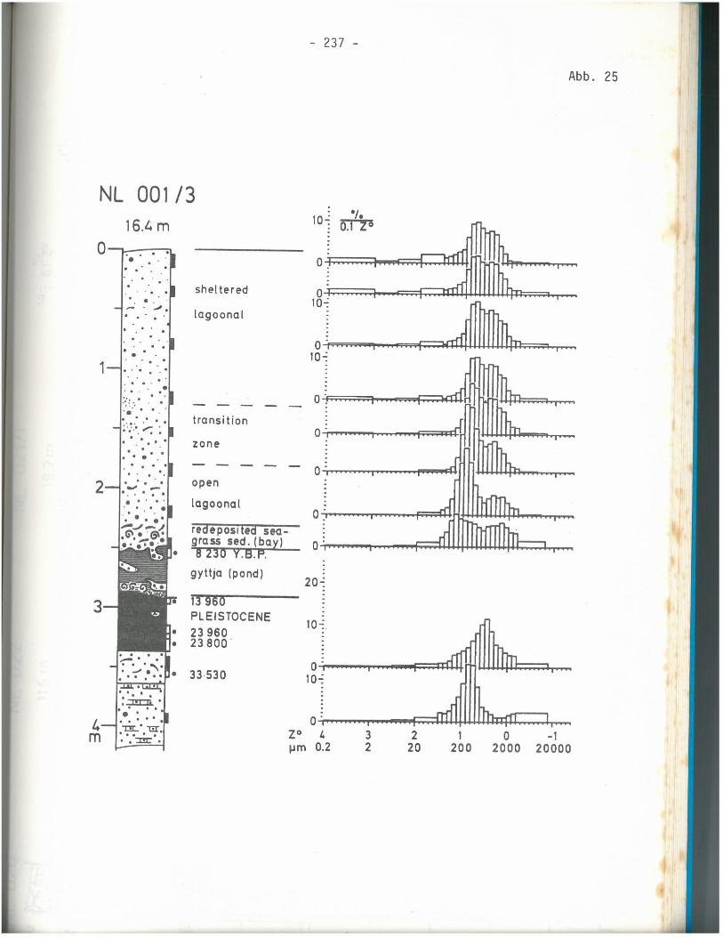
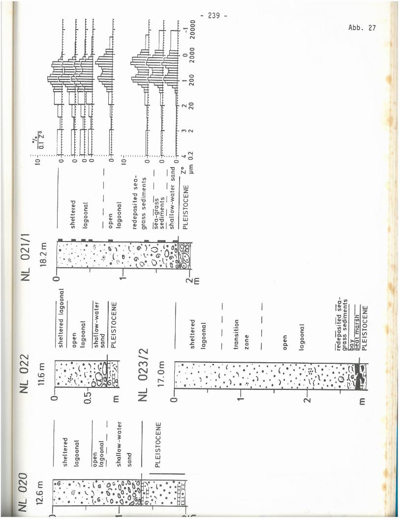
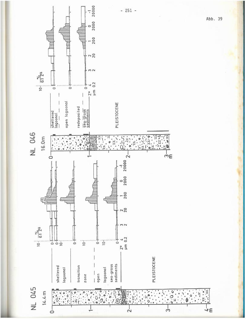
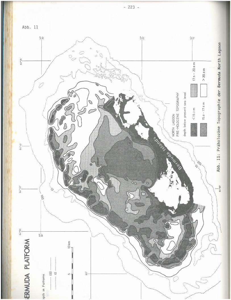
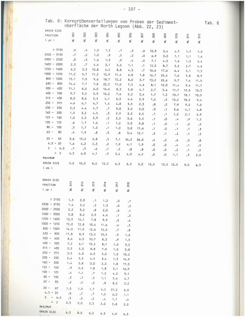
Kuhn et al (1981) undertook vibration coring in the Bermuda Platform. These penetrated the Holocene sediments and a few decimeters of the underling Pleistocene deposits. They indicated that the Holocene sediments also contain reefs and that depressions or sink holes are present near shore in the underlying deposits. Peat and gyttga are present at about 20 m below sea level in these depressions. Exp also found peat deposits below the recent sediments at about 17 to 19 m below sea level.
Some of the logs of the vibration coring by Kuhn carried out for his Ph.D. thesis (1984) along with the location plan are appended to this report. The cores encountered from about 1.2 m to in excess of 4 m of Holocene sediments overlying Pleistocene deposits
Pleistocene Deposits
The youngest Pleistocene deposit is the Southampton Formation which consists of lightly cemented aeolianite and calcarenite limestone. Uncemented sand layers and pockets are common in this deposit.
Exp found horizontally layered calcarenite which is probably a shallow water marine deposit below the Holocene sediments at depths of 17 to 19 m and these extended down to about 40 to 45 m. Below this depth harder limestone consisting of Biomicrite, coral and calcarenite was encountered
Kuhn et al (1981) also indicate that partly cemented reefal and lagoonal sediments underlie the Holocene deposits and are up to 20 m thick. Unfortunately, these deposits are not described. They extended to a lower seismic layer (not described) which was found at a depth of about 15 to 17 m near shore and sloped to 30 to 40 near the rim of the platform.

Brunell Ltd. Ltd. Geotechnical Investigation
Approaches to Bermuda BRM-00603466-A0
5
Conclusions Based on the geological information and limited investigations, it is expected that the site would be underlain by Holocene deposits of coral and loose sediments. At depths of less than 17 m weak Pleistocene limestone may be encountered. References
1. Exp Services Inc. (2014) Geotechnical Report, Heritage and Kings Wharf,
Royal Naval Dockyards, Bermuda; dated July 30, 2013
2. Gees, R.A. and Medioli, F. (1970), A continuous seismic survey of the
Bermuda Platform, Part I: Castle Harbour; Marine Sediment, Vol. 6, No, 1, pp
21 to 25
3. Kuhn, G., Torunsky, H. and Meischner, D. (1981), Reef Growth and Lagoon
Development in the Bermuda Recorded by Seismic Reflection Profiling and
Deep Vibration Coring,; Abstract in The Reef and Man, Proceedings of the
Fourth International Coral Reef Symposium, Volume 1.
4. Kuhn, G (1984( Sedimentations-Geschicte der Bermuda North Lagoon im
Holozan. Teil II (Anhang); Dissertaion zur Erlangung des Doktorgrades
Mathematisch-Naturwissenschaftlichen Fachbereiche der Georg-August-
Universitat zu Gottingen
5. Rowe, M. P. (1998) An Explanation of the Geology of Bermuda, Second
Addition, Bermuda Government, Ministry of the Environment
6. Vacher, H.L., Rowe, M. P. and Garrett, P. (1989) The Geological Map of
Bermuda, Scale 1:25,000, Oxford Cartographers, London, Bermuda Gov.,
Ministry of Works & Engineering

Brunell Ltd. Ltd. Geotechnical Investigation
Approaches to Bermuda BRM-00603466-A0
6
3. Procedure
Drilling Program
The drilling of the boreholes was carried out between March 22 and April 5, 2014
The number of boreholes and their locations and depths were specified by the Bermuda Ministry of Works & Engineering. A total of fourteen sampled boreholes were drilled at locations shown in Sheets MPW-61-52-77-G2 (North Channel), MPW-61-52-77-G3 (South Channel) and MPW-61-52-77-G4 (The Narrows), Borehole 13 was drilled near the entrance to the channel leading to St Georges. This borehole is not shown on the plans but is at N141912.326 - E557810.859.
Borehole 11 was advanced and it was discovered that the water depth was greater than the borehole depth specified by the Bermuda Ministry of Works & Engineering. Therefore no sampling was required.
Borehole 12 could not be completed on the day they were started due to rough seas. This hole was continued at a later date as Borehole 12-2, but could also not be completed to the specified depth due to rough seas. Based on discussions with the Ministry of Works & Engineering, it was decided to relocate borehole 12 close to the reefs adjacent to borehole 11 denoted as BH 11-2.
The drilled boreholes were advanced to various depths ranging between -14.0 to -14.9 m below Chart Datum, except for Borehole 12-2 which could only be drilled to -10.4 m below Chart datum. The fieldwork was supervised on a full-time basis by a member of exp’s engineering staff who directed the drilling and sampling operation, logged borehole data, and retrieved soil and rock samples for subsequent laboratory testing and identification.
All borehole locations were determined in the field and approved by Ministry of Works & Engineering. All final drilling locations were surveyed and the corresponding elevations were referenced to the Chart Datum.
Drilling through soil and weak rock was completed using rotary wash drilling techniques until the stronger rock was encountered. Boreholes were advanced through rock using diamond drill rock coring methods. The boreholes were advanced using a trailer mounted CME 55 drill rig operated by a specialist drilling contractor, Aardvark Drilling Inc. The drilling rig was equipped with a CME automatic trip hammer.
Sampling of overburden was obtained using a 50 mm outside diameter (O.D.) split-barrel sampler in accordance with Standard Penetration Test (SPT) procedures (ASTM D1586). Samples were taken at approximately 1.5 m intervals of depth. This was supplemented with samples taken with a 75 mm O.D split-barrel sampler.

Brunell Ltd. Ltd. Geotechnical Investigation
Approaches to Bermuda BRM-00603466-A0
7
The N values on the logs were corrected for the larger sampler. Sampling of the bedrock was performed by diamond core drilling, using a 1.5 m long HQ3 triple-barrel wireline core barrel.
The recovered soil samples and rock cores were visually examined and logged in the field by an exp’ field engineer. The core recovery was measured and the rock quality designation (RQD) as a standard parameter in drill core logging was determined. The final soil boring logs and rock core logs are are presented on Drawings 2 to 14. The photographs of rock cores are included in Appendix A.
All split barrel samples were placed in properly labeled sealed plastic bags. The rock cores were placed in properly labeled wooden core boxes. The soil samples and one rock core specimen were shipped to the exp laboratory in Brampton, Ontario for laboratory testing.
Laboratory Testing
All of the soil samples were tested for moisture content. In addition, twelve selected soil samples were subjected to grain size analysis and five soil samples were tested for heavy metals. Only one piece of rock core was suitable for compressive strength testing.
The soil testing and sample locations are summarized on Table 1. All soil testing was carried out at the exp laboratory in Brampton, Ontario, Canada.
Table 1: Summary of Soils Laboratory Testing
BH Sample Depth
m) Test 1 Test 2
1 SS3 16.3 Grain size analysis
2 SS1 15.8 Grain size analysis Heavy metals
3 SS3 12.3 Grain size analysis
3 SS4 15.6 Heavy metals
Grain size analysis
5 SS2 14.3 Grain size analysis
7 SS1 11.7 Grain size analysis Heavy metals
7 SS3 15.7 Grain size analysis
8 SS1 14.4 Grain size analysis
Brunell Ltd. Ltd. Geotechnical Investigation
Approaches to Bermuda BRM-00603466-A0
8
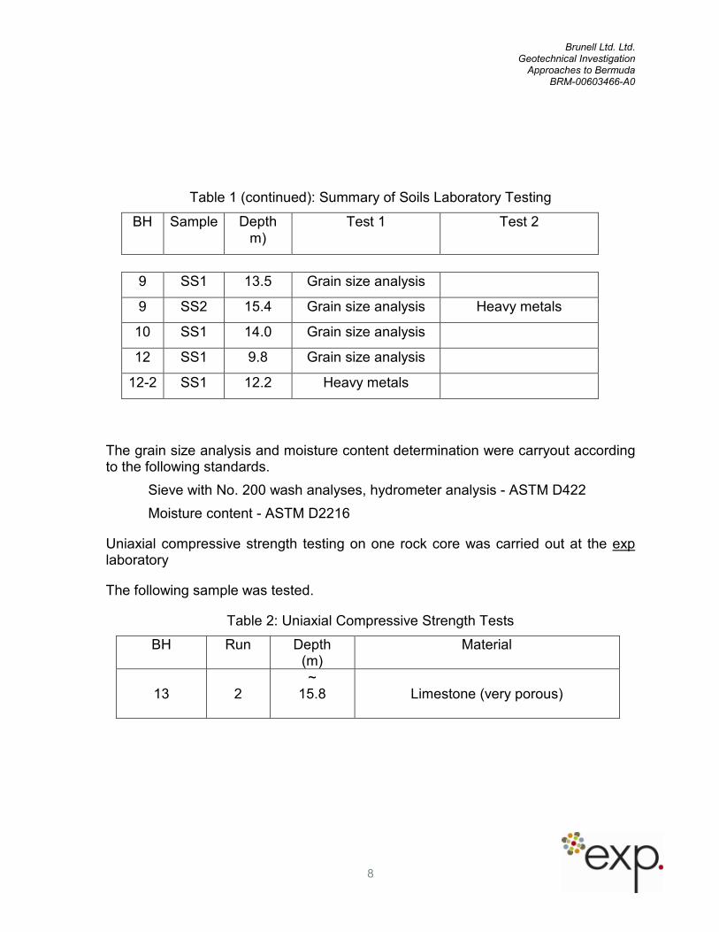
Table 1 (continued): Summary of Soils Laboratory Testing
BH Sample Depth
m) Test 1 Test 2
9 SS1 13.5 Grain size analysis
9 SS2 15.4 Grain size analysis Heavy metals
10 SS1 14.0 Grain size analysis
12 SS1 9.8 Grain size analysis
12-2 SS1 12.2 Heavy metals
The grain size analysis and moisture content determination were carryout according to the following standards.
Sieve with No. 200 wash analyses, hydrometer analysis - ASTM D422
Moisture content - ASTM D2216
Uniaxial compressive strength testing on one rock core was carried out at the exp laboratory
The following sample was tested.
Table 2: Uniaxial Compressive Strength Tests
BH Run Depth (m)
Material
13
2
~ 15.8
Limestone (very porous)

Brunell Ltd. Ltd. Geotechnical Investigation
Approaches to Bermuda BRM-00603466-A0
9
4. Subsurface Conditions
The detailed subsurface conditions in each borehole presented on the attached borehole and core logs. It should be noted that the soil boundaries indicated on the borehole logs are inferred from non-continuous sampling and observations during drilling. These boundaries are intended to reflect approximate transition zones for the purpose of geotechnical design and should not be interpreted as exact planes of geological change.
The "Notes on Sample Description" preceding the borehole logs form an integral part of and should be read in conjunction with this report. The Explanatory Sheet for the core logs define the terms and symbols used on the logs.
The following is a brief description of the subsurface encountered during the investigation:
Holocene Sediment
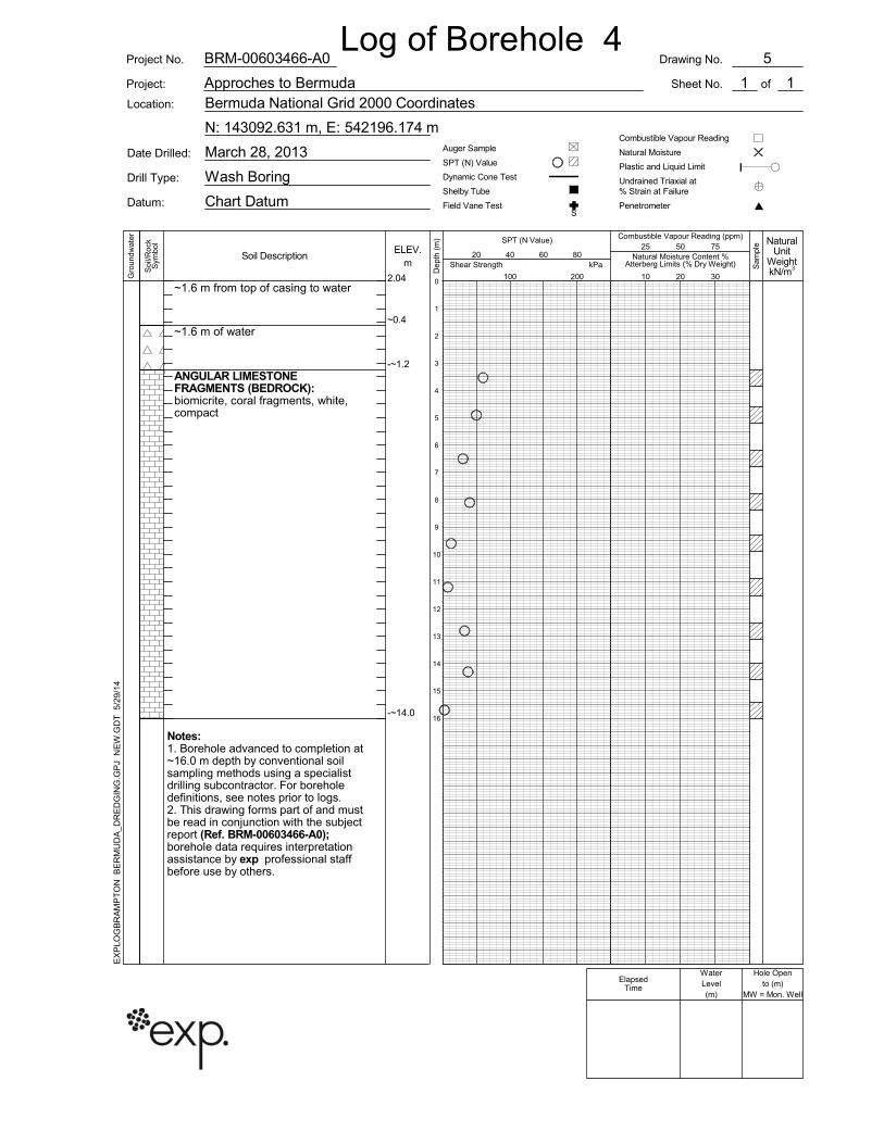
Holocene sediments were encountered in all of the boreholes expect for Boreholes 4, 6, 12-2 and 13 where limestone bedrock was found.
The Holocene sediments consist mainly of sand which varies texturally from fine to medium sand to fine to coarse sand. It contains a trace to some of silt and gravel as well as shell fragments and occasional pieces of coral. Layers of sand and gravel or gravelly sand were noted in the deposit in Boreholes 7 and 11-2. In Borehole 10, the sample from 14 m depth contained some clay sized material/ The Holocene sediments are generally white and in a very loose to loose condition.
Table 3 below summarizes the percentages of silt, sand and gravel found in the tested samples.
Table 3: Summary of Grain Size Analyses on Holocene Sediment
BH Sample Depth m)
Percent Silt Percent Sand Percent Gravel
1 SS3 16.3 20 72 8
2 SS1 15.8 14 86 0
3 SS3 12.3 11 81 8
3 SS4 15.6 28 68 4
5 SS2 14.3 6 94 0

Brunell Ltd. Ltd. Geotechnical Investigation
Approaches to Bermuda BRM-00603466-A0
10
Table 3 (continued): Summary of Grain Size Analyses on Holocene Sediment
BH Sample Depth
m) Percent Silt Percent Sand Percent Gravel
7 SS1 11.7 10 89 1
7 SS3 15.7 10 65 25
8 SS1 14.4 13 86 1
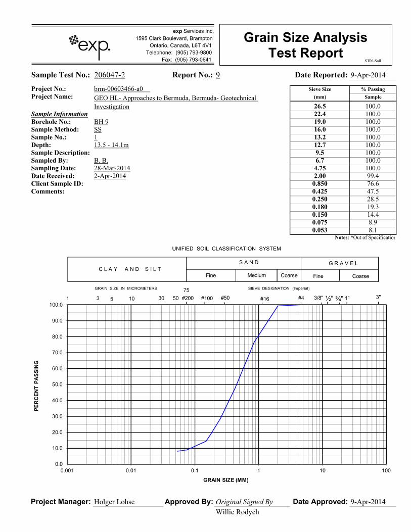
9 SS1 13.5 9 91 0
9 SS2 15.4 13 65 22
10 SS1 14.0 Silt 23
Clay 17 50 10
12 SS1 9.8 19 45 36
Pleistocene Bedrock
Pleistocene limestone bedrock was encountered in Boreholes 4, 6, 10, 11-2, 12, and 13. It was found at the surface in Boreholes 4, 6, 12, 12-2 and 13. In Borehole 10, about 1.5 m of Holocene sediments overlies the limestone and in Borehole 11-2 about 6.7 m of Holocene sediments overlie the limestone.
The limestone was easily penetrated by wash boring in the boreholes, this making identification difficult. The samples retrieved with the split barrel sampler consisted of angular limestone sand and gravel. Standard penetration test N values in this material range from 12 to 24 blows per 300 mm in Borehole 4 and 1 to 3 blows in Boreholes 6 and 10. In Borehole 11-2, the N values ranged from 5 to 18 blows.
The limestone is fine grained with fossils fragments and coral fragments. It is a white to light tan colour
The limestone in Borehole 13 was cred with a HQ3 core barrel for a depth of 3 m. The core recovery in the two Runs ranged from 100 percent in Run 1 to 77 percent in Run 2. The low recovery in Run 2 is attributed to cavities in the rock. The bedding of the rock is close to very close and the RQD of the rock ranges from 14 to 22 percent.

Brunell Ltd. Ltd. Geotechnical Investigation
Approaches to Bermuda BRM-00603466-A0
11
Only one piece of limestone was suitable for uniaxial compressive strength testing. The specimen from Borehole 13 at 15.8 m was found to have a uniaxial compressive strength of 6.7 MPa. This low value is attributed to the numerous voids in the specimen. The actual rock fragments are hard and can be scratched with a knife with effort. The corresponding estimated compressive strength ranges from about 15 to 50 MPa
Brunell Ltd. Ltd. Geotechnical Investigation
Approaches to Bermuda BRM-00603466-A0
12
5. Chemical Test Results
Five samples were submitted to a laboratory accredited by the Canadian Association for Laboratory Accreditation (CALA) for testing selected inorganic parameters listed in the MOE document “Soil, Ground Water and Sediment Standards for Use Under Part XV.1 of the Environmental Protection Act” – revised April 15, 2011 in accordance with Ontario Regulation (O.Reg.) 153/04 (as amended by O.Reg. 511/09).
The testing was carried out to provide a preliminary assessment of the environmental quality of the soils at the site and to assist in selection of disposal options for excess material expected to be generated during construction. The
Certificates of Analysis are provided in Appendix C.
The concentrations of all metals and inorganic parameters met the Table 2 criteria given for parkland and residential property use.
It is expected that the soil can be disposed of at residential/parkland sites or commercial/industrial sites accepting fill. However, the disposal site owners must review the test data as well as the borehole information to determine if the material is acceptable for their site.

Brunell Ltd. Ltd. Geotechnical Investigation
Approaches to Bermuda BRM-00603466-A0
13
6. Discussion
It is assumed that the dredging contractors will make their own decision on the suitable equipment for the dredging conditions at this site based on the findings in the boreholes, on additional investigation if required, and on their experience and requirements. The boreholes do not differentiate where the dredging conditions change laterally.
The Holocene sediment should be easy to dredge with suction dredges. It is expected that the porous limestone can be dredged with suction dredges equipped with rock cutters Table 5 summarizes the anticipated dredging conditions.
Table 5: Anticipated Dredging Conditions
Borehole Elevation (m) Chart Datum
Material Comments
1 -14.3 to -14.9 Fine to coarse sand Suction dredging
2 -13.8 to -14.4 Fine to coarse sand Suction dredging
3 -6.6 to -14.0 Fine to coarse sand Suction dredging
4 -1.2 to -14.0 Limestone Suction dredge equipped
with rock cutters
5 -10.9 to -14.2 Fine to medium sand Suction dredging
6 -11.3 to -14.1 Limestone Suction dredge equipped
with rock cutters
7 -9.4 to -14.0 Sand and gravel, sand Suction dredge may require
h rock cutters for gravel
8 -11.9 to -14.1 Fine to medium sand Suction dredging
9 -11.5 to -14.0 Sand Suction dredging
10 -11.4 to -12.9 Fine to coarse sand Suction dredging
10 -12.9 to -14.9 Limestone Suction dredge equipped
with rock cutters

Brunell Ltd. Ltd. Geotechnical Investigation
Approaches to Bermuda BRM-00603466-A0
14
Table 5 (continued): Anticipated Dredging Conditions
Borehole Elevation (m) Chart Datum
Material Comments
11-2 -4.8 to -11.6 Gravelly sand/silty sand Suction dredging
11-2 -11.6 to -14.9 Limestone Suction dredge equipped
with rock cutters
12 Below -7.1 Possible Limestone Suction dredge equipped
with rock cutters
12-2 Below -8.7 Limestone Suction dredge equipped
with rock cutters
13 -10.9 to -14.2 Limestone Suction dredge equipped
with rock cutters
The following permanent slopes are recommended for the sides of the dredged channels:
Holocene sediments 1 vertical to 2.5 horizontal
Pleistocene bedrock 2 vertical to 1 horizontal
Provisions should be made to allow the fines to settle out of the dredge water before it is returned to the ocean.


Brunell Ltd. Ltd. Geotechnical Investigation
Approaches to Bermuda BRM-00603466
Drawings Borehole Location Plan
and Borehole Logs

~1.6 m from top of casing to water
~14.65 m of water
FINE TO COARSE SAND: some silt,trace of gravel, shells, white, veryloose
~0.3
-~14.3
-~14.9
Notes:1. Borehole advanced to completion at~17.9 m depth by conventional soilsampling methods using a specialistdrilling subcontractor. For boreholedefinitions, see notes prior to logs.2. This drawing forms part of and mustbe read in conjunction with the subjectreport (Ref. BRM-00603466-A0); borehole data requires interpretationassistance by exp professional staffbefore use by others.
March 29, 2013
Wash Boring
Chart Datum
Drill Type:
Datum:
Auger Sample
SPT (N) Value
Dynamic Cone Test
Shelby Tube
Field Vane TestS
N: 137948.424 m, E: 543090.304 mCombustible Vapour Reading
Natural Moisture
Plastic and Liquid Limit
Undrained Triaxial at% Strain at Failure
Penetrometer
Location:
Date Drilled:
Bermuda National Grid 2000 Coordinates
Combustible Vapour Reading (ppm)
ELEV.m
1.95 10 20 30
Soil Description
NaturalUnit
WeightkN/m3
Natural Moisture Content %Atterberg Limits (% Dry Weight)
100
kPaShear Strength20 40 60 80
200
25 50 75SPT (N Value)
Dep
th (
m)
Sam
ple
Gro
undw
ater
Soi
l/Roc
kS
ymbo
l
Drawing No.
of
Log of Borehole 1
WaterLevel(m)
Hole Opento (m)
MW = Mon. Well
2
Sheet No.Approches to Bermuda
BRM-00603466-A0
Project: 1
0
1
2
3
4
5
6
7
8
9
10
11
12
13
14
15
16
17
1
Project No.
ElapsedTime
EX
PLO
GB
RA
MP
TO
N B
ER
MU
DA
_DR
ED
GIN
G.G
PJ
NE
W.G
DT
5/2
9/1
4

~1.6 m from top of casing to water
~14.2 m of water
FINE TO COARSE SAND: trace ofsilt and gravel, shells, white, loose
~0.4
-~13.8
-~14.4
Notes:1. Borehole advanced to completion at~16.4 m depth by conventional soilsampling methods using a specialistdrilling subcontractor. For boreholedefinitions, see notes prior to logs.2. This drawing forms part of and mustbe read in conjunction with the subjectreport (Ref. BRM-00603466-A0); borehole data requires interpretationassistance by exp professional staffbefore use by others.
March 29, 2013
Wash Boring
Chart Datum
Drill Type:
Datum:
Auger Sample
SPT (N) Value
Dynamic Cone Test
Shelby Tube
Field Vane TestS
N: 139706.814 m, E: 543195.351 mCombustible Vapour Reading
Natural Moisture
Plastic and Liquid Limit
Undrained Triaxial at% Strain at Failure
Penetrometer
Location:
Date Drilled:
Bermuda National Grid 2000 Coordinates
Combustible Vapour Reading (ppm)
ELEV.m
2.03 10 20 30
Soil Description
NaturalUnit
WeightkN/m3
Natural Moisture Content %Atterberg Limits (% Dry Weight)
100
kPaShear Strength20 40 60 80
200
25 50 75SPT (N Value)
Dep
th (
m)
Sam
ple
Gro
undw
ater
Soi
l/Roc
kS
ymbo
l
Drawing No.
of
Log of Borehole 2
WaterLevel(m)
Hole Opento (m)
MW = Mon. Well
3
Sheet No.Approches to Bermuda
BRM-00603466-A0
Project: 1
0
1
2
3
4
5
6
7
8
9
10
11
12
13
14
15
16
1
Project No.
ElapsedTime
EX
PLO
GB
RA
MP
TO
N B
ER
MU
DA
_DR
ED
GIN
G.G
PJ
NE
W.G
DT
5/2
9/1
4

~1.6 m from top of casing to water
~7.3 m of water
FINE TO COARSE SAND: some silt,trace of gravel, white, very loose
FINE TO COARSE SAND: some silt,some gravel and shells, white, veryloose
~0.6
-~6.6
-~7.8
-~14.0
Notes:1. Borehole advanced to completion at~16.2 m depth by conventional soilsampling methods using a specialistdrilling subcontractor. For boreholedefinitions, see notes prior to logs.2. This drawing forms part of and mustbe read in conjunction with the subjectreport (Ref. BRM-00603466-A0); borehole data requires interpretationassistance by exp professional staffbefore use by others.
March 29, 2013
Wash Boring
Chart Datum
Drill Type:
Datum:
Auger Sample
SPT (N) Value
Dynamic Cone Test
Shelby Tube
Field Vane TestS
N: 142444.565 m, E: 542458.502 mCombustible Vapour Reading
Natural Moisture
Plastic and Liquid Limit
Undrained Triaxial at% Strain at Failure
Penetrometer
Location:
Date Drilled:
Bermuda National Grid 2000 Coordinates
Combustible Vapour Reading (ppm)
ELEV.m
2.24 10 20 30
Soil Description
NaturalUnit
WeightkN/m3
Natural Moisture Content %Atterberg Limits (% Dry Weight)
100
kPaShear Strength20 40 60 80
200
25 50 75SPT (N Value)
Dep
th (
m)
Sam
ple
Gro
undw
ater
Soi
l/Roc
kS
ymbo
l
Drawing No.
of
Log of Borehole 3
WaterLevel(m)
Hole Opento (m)
MW = Mon. Well
4
Sheet No.Approches to Bermuda
BRM-00603466-A0
Project: 1
0
1
2
3
4
5
6
7
8
9
10
11
12
13
14
15
16
1
Project No.
ElapsedTime
EX
PLO
GB
RA
MP
TO
N B
ER
MU
DA
_DR
ED
GIN
G.G
PJ
NE
W.G
DT
5/2
9/1
4
~1.6 m from top of casing to water
~1.6 m of water
ANGULAR LIMESTONEFRAGMENTS (BEDROCK):biomicrite, coral fragments, white,compact
~0.4
-~1.2
-~14.0
Notes:1. Borehole advanced to completion at~16.0 m depth by conventional soilsampling methods using a specialistdrilling subcontractor. For boreholedefinitions, see notes prior to logs.2. This drawing forms part of and mustbe read in conjunction with the subjectreport (Ref. BRM-00603466-A0); borehole data requires interpretationassistance by exp professional staffbefore use by others.
March 28, 2013
Wash Boring
Chart Datum
Drill Type:
Datum:
Auger Sample
SPT (N) Value
Dynamic Cone Test
Shelby Tube
Field Vane TestS
N: 143092.631 m, E: 542196.174 mCombustible Vapour Reading
Natural Moisture
Plastic and Liquid Limit
Undrained Triaxial at% Strain at Failure
Penetrometer
Location:
Date Drilled:
Bermuda National Grid 2000 Coordinates
Combustible Vapour Reading (ppm)
ELEV.m
2.04 10 20 30
Soil Description
NaturalUnit
WeightkN/m3
Natural Moisture Content %Atterberg Limits (% Dry Weight)
100
kPaShear Strength20 40 60 80
200
25 50 75SPT (N Value)
Dep
th (
m)
Sam
ple
Gro
undw
ater
Soi
l/Roc
kS
ymbo
l
Drawing No.
of
Log of Borehole 4
WaterLevel(m)
Hole Opento (m)
MW = Mon. Well
5
Sheet No.Approches to Bermuda
BRM-00603466-A0
Project: 1
0
1
2
3
4
5
6
7
8
9
10
11
12
13
14
15
16
1
Project No.
ElapsedTime
EX
PLO
GB
RA
MP
TO
N B
ER
MU
DA
_DR
ED
GIN
G.G
PJ
NE
W.G
DT
5/2
9/1
4

~1.6 m from top of casing to water
~11.4 m of water
FINE TO MEDIUM SAND: trace ofsilt, white, wet, loose
~0.6
-~10.9
-~14.2
Notes:1. Borehole advanced to completion at~16.4 m depth by conventional soilsampling methods using a specialistdrilling subcontractor. For boreholedefinitions, see notes prior to logs.2. This drawing forms part of and mustbe read in conjunction with the subjectreport (Ref. BRM-00603466-A0); borehole data requires interpretationassistance by exp professional staffbefore use by others.
March 25, 2013
Wash Boring
Chart Datum
Drill Type:
Datum:
Auger Sample
SPT (N) Value
Dynamic Cone Test
Shelby Tube
Field Vane TestS
N: 135055.829 m, E: 545294.392 mCombustible Vapour Reading
Natural Moisture
Plastic and Liquid Limit
Undrained Triaxial at% Strain at Failure
Penetrometer
Location:
Date Drilled:
Bermuda National Grid 2000 Coordinates
Combustible Vapour Reading (ppm)
ELEV.m
2.16 10 20 30
Soil Description
NaturalUnit
WeightkN/m3
Natural Moisture Content %Atterberg Limits (% Dry Weight)
100
kPaShear Strength20 40 60 80
200
25 50 75SPT (N Value)
Dep
th (
m)
Sam
ple
Gro
undw
ater
Soi
l/Roc
kS
ymbo
l
Drawing No.
of
Log of Borehole 5
WaterLevel(m)
Hole Opento (m)
MW = Mon. Well
6
Sheet No.Approches to Bermuda
BRM-00603466-A0
Project: 1
0
1
2
3
4
5
6
7
8
9
10
11
12
13
14
15
16
1
Project No.
ElapsedTime
EX
PLO
GB
RA
MP
TO
N B
ER
MU
DA
_DR
ED
GIN
G.G
PJ
NE
W.G
DT
5/2
9/1
4

~1.3 m from top of casing to water
~11.85 m of water
LIMESTONE FRAGMENTS: trace ofsand, white, very loose(Probable Bedrock)ANGULAR LIMESTONEFRAGMENTS (BEDROCK) L: white,very loose
~0.6
-~11.3
-~11.8
-~14.1
Notes:1. Borehole advanced to completion at~16.0 m depth by conventional soilsampling methods using a specialistdrilling subcontractor. For boreholedefinitions, see notes prior to logs.2. This drawing forms part of and mustbe read in conjunction with the subjectreport (Ref. BRM-00603466-A0); borehole data requires interpretationassistance by exp professional staffbefore use by others.
March 25, 2013
Wash Boring
Chart Datum
Drill Type:
Datum:
Auger Sample
SPT (N) Value
Dynamic Cone Test
Shelby Tube
Field Vane TestS
N: 134944.078 m, E: 546403.958 mCombustible Vapour Reading
Natural Moisture
Plastic and Liquid Limit
Undrained Triaxial at% Strain at Failure
Penetrometer
Location:
Date Drilled:
Bermuda National Grid 2000 Coordinates
Combustible Vapour Reading (ppm)
ELEV.m
1.90 10 20 30
Soil Description
NaturalUnit
WeightkN/m3
Natural Moisture Content %Atterberg Limits (% Dry Weight)
100
kPaShear Strength20 40 60 80
200
25 50 75SPT (N Value)
Dep
th (
m)
Sam
ple
Gro
undw
ater
Soi
l/Roc
kS
ymbo
l
Drawing No.
of
Log of Borehole 6
WaterLevel(m)
Hole Opento (m)
MW = Mon. Well
7
Sheet No.Approches to Bermuda
BRM-00603466-A0
Project: 1
0
1
2
3
4
5
6
7
8
9
10
11
12
13
14
15
16
1
Project No.
ElapsedTime
EX
PLO
GB
RA
MP
TO
N B
ER
MU
DA
_DR
ED
GIN
G.G
PJ
NE
W.G
DT
5/2
9/1
4

~1.7 m from top of casing to water
~10 m of water
FINE TO MEDIUM SAND: trace ofshells, white, very loose
SAND AND GRAVEL: white,, veryloose
FINE TO MEDIUM SAND: trace ofgravel, white, compact
~0.6
-~9.4
-~11.4
-~13.4
-~14.0
Notes:1. Borehole advanced to completion at~17.0 m depth by conventional soilsampling methods using a specialistdrilling subcontractor. For boreholedefinitions, see notes prior to logs.2. This drawing forms part of and mustbe read in conjunction with the subjectreport (Ref. BRM-00603466-A0); borehole data requires interpretationassistance by exp professional staffbefore use by others.
March 25, 2013
Wash Boring
Chart Datum
Drill Type:
Datum:
Auger Sample
SPT (N) Value
Dynamic Cone Test
Shelby Tube
Field Vane TestS
N: 135200.430 m, E: 546920.567 mCombustible Vapour Reading
Natural Moisture
Plastic and Liquid Limit
Undrained Triaxial at% Strain at Failure
Penetrometer
Location:
Date Drilled:
Bermuda National Grid 2000 Coordinates
Combustible Vapour Reading (ppm)
ELEV.m
2.30 10 20 30
Soil Description
NaturalUnit
WeightkN/m3
Natural Moisture Content %Atterberg Limits (% Dry Weight)
100
kPaShear Strength20 40 60 80
200
25 50 75SPT (N Value)
Dep
th (
m)
Sam
ple
Gro
undw
ater
Soi
l/Roc
kS
ymbo
l
Drawing No.
of
Log of Borehole 7
WaterLevel(m)
Hole Opento (m)
MW = Mon. Well
8
Sheet No.Approches to Bermuda
BRM-00603466-A0
Project: 1
0
1
2
3
4
5
6
7
8
9
10
11
12
13
14
15
16
17
1
Project No.
ElapsedTime
EX
PLO
GB
RA
MP
TO
N B
ER
MU
DA
_DR
ED
GIN
G.G
PJ
NE
W.G
DT
5/2
9/1
4

~1.6 m from top of casing to water
~ 12.8 m of water
FINE TO MEDIUM SAND: trace ofsilt and shells, white, very loose
~0.8
-~11.9
-~14.1
Notes:1. Borehole advanced to completion at~16.6 m depth by conventional soilsampling methods using a specialistdrilling subcontractor. For boreholedefinitions, see notes prior to logs.2. This drawing forms part of and mustbe read in conjunction with the subjectreport (Ref. BRM-00603466-A0); borehole data requires interpretationassistance by exp professional staffbefore use by others.
March 28, 2013
Wash Boring
Chart Datum
Drill Type:
Datum:
Auger Sample
SPT (N) Value
Dynamic Cone Test
Shelby Tube
Field Vane TestS
N: 137018.497 m, E: 549672.241 mCombustible Vapour Reading
Natural Moisture
Plastic and Liquid Limit
Undrained Triaxial at% Strain at Failure
Penetrometer
Location:
Date Drilled:
Bermuda National Grid 2000 Coordinates
Combustible Vapour Reading (ppm)
ELEV.m
2.51 10 20 30
Soil Description
NaturalUnit
WeightkN/m3
Natural Moisture Content %Atterberg Limits (% Dry Weight)
100
kPaShear Strength20 40 60 80
200
25 50 75SPT (N Value)
Dep
th (
m)
Sam
ple
Gro
undw
ater
Soi
l/Roc
kS
ymbo
l
Drawing No.
of
Log of Borehole 8
WaterLevel(m)
Hole Opento (m)
MW = Mon. Well
9
Sheet No.Approches to Bermuda
BRM-00603466-A0
Project: 1
0
1
2
3
4
5
6
7
8
9
10
11
12
13
14
15
16
1
Project No.
ElapsedTime
EX
PLO
GB
RA
MP
TO
N B
ER
MU
DA
_DR
ED
GIN
G.G
PJ
NE
W.G
DT
5/2
9/1
4

~1.5 m from top of casing to water
~12.8 m of water
SILTY SAND: shells, white, loose tovery loose
PEAT: dark brown, looseSILTY SAND: shells, white, loose
~0.8
-~12.0
-~14.2-~14.6-~15.1
Notes:1. Borehole advanced to completion at~17.4 m depth by conventional soilsampling methods using a specialistdrilling subcontractor. For boreholedefinitions, see notes prior to logs.2. This drawing forms part of and mustbe read in conjunction with the subjectreport (Ref. BRM-00603466-A0); borehole data requires interpretationassistance by exp professional staffbefore use by others.
April 3, 2014
Wash Boring
Chart Datum
Drill Type:
Datum:
Auger Sample
SPT (N) Value
Dynamic Cone Test
Shelby Tube
Field Vane TestS
N: 137042.404 m, E: 549699.220 mCombustible Vapour Reading
Natural Moisture
Plastic and Liquid Limit
Undrained Triaxial at% Strain at Failure
Penetrometer
Location:
Date Drilled:
Bermuda National Grid 2000 Coordinates
Combustible Vapour Reading (ppm)
ELEV.m
2.31 10 20 30
Soil Description
NaturalUnit
WeightkN/m3
Natural Moisture Content %Atterberg Limits (% Dry Weight)
100
kPaShear Strength20 40 60 80
200
25 50 75SPT (N Value)
Dep
th (
m)
Sam
ple
Gro
undw
ater
Soi
l/Roc
kS
ymbo
l
Drawing No.
of
Log of Borehole 8-2
WaterLevel(m)
Hole Opento (m)
MW = Mon. Well
9
Sheet No.Approches to Bermuda
BRM-00603466-A0
Project: 1
0
1
2
3
4
5
6
7
8
9
10
11
12
13
14
15
16
17
1
Project No.
ElapsedTime
EX
PLO
GB
RA
MP
TO
N B
ER
MU
DA
_DR
ED
GIN
G.G
PJ
NE
W.G
DT
5/2
9/1
4

~1.7 m from top of casing to water
~ 11.8 m of water
FINE TO MEDIUM SAND: trace ofshells, white to light brown, very looseFINE TO COARSE SAND: some silt,trace of shells, white, loose
~0.3
-~11.5
-~12.5
-~14.0
Notes:1. Borehole advanced to completion at~16.0 m depth by conventional soilsampling methods using a specialistdrilling subcontractor. For boreholedefinitions, see notes prior to logs.2. This drawing forms part of and mustbe read in conjunction with the subjectreport (Ref. BRM-00603466-A0); borehole data requires interpretationassistance by exp professional staffbefore use by others.
March 28, 2013
Wash Boring
Chart Datum
Drill Type:
Datum:
Auger Sample
SPT (N) Value
Dynamic Cone Test
Shelby Tube
Field Vane TestS
N: 137278.557 m, E: 548976.183 mCombustible Vapour Reading
Natural Moisture
Plastic and Liquid Limit
Undrained Triaxial at% Strain at Failure
Penetrometer
Location:
Date Drilled:
Bermuda National Grid 2000 Coordinates
Combustible Vapour Reading (ppm)
ELEV.m
2.03 10 20 30
Soil Description
NaturalUnit
WeightkN/m3
Natural Moisture Content %Atterberg Limits (% Dry Weight)
100
kPaShear Strength20 40 60 80
200
25 50 75SPT (N Value)
Dep
th (
m)
Sam
ple
Gro
undw
ater
Soi
l/Roc
kS
ymbo
l
Drawing No.
of
Log of Borehole 9
WaterLevel(m)
Hole Opento (m)
MW = Mon. Well
10
Sheet No.Approches to Bermuda
BRM-00603466-A0
Project: 1
0
1
2
3
4
5
6
7
8
9
10
11
12
13
14
15
16
1
Project No.
ElapsedTime
EX
PLO
GB
RA
MP
TO
N B
ER
MU
DA
_DR
ED
GIN
G.G
PJ
NE
W.G
DT
5/2
9/1
4

~1.7 m from top of casing to water
~ 12.0 m of water
FINE TO COARSE SAND: some silt,clay and gravel and shells, white,veryloose
ANGULAR LIMESTONEFRAGMENTS: some angular sand,white, very loose(Possible Bedrock)
~0.6
-~11.4
-~12.9
-~14.1
Notes:1. Borehole advanced to completion at~17.4 m depth by conventional soilsampling methods using a specialistdrilling subcontractor. For boreholedefinitions, see notes prior to logs.2. This drawing forms part of and mustbe read in conjunction with the subjectreport (Ref. BRM-00603466-A0); borehole data requires interpretationassistance by exp professional staffbefore use by others.
March 28, 2013
Wash Boring
Chart Datum
Drill Type:
Datum:
Auger Sample
SPT (N) Value
Dynamic Cone Test
Shelby Tube
Field Vane TestS
N: 138984.904 m, E: 550890.463 mCombustible Vapour Reading
Natural Moisture
Plastic and Liquid Limit
Undrained Triaxial at% Strain at Failure
Penetrometer
Location:
Date Drilled:
Bermuda National Grid 2000 Coordinates
Combustible Vapour Reading (ppm)
ELEV.m
2.27 10 20 30
Soil Description
NaturalUnit
WeightkN/m3
Natural Moisture Content %Atterberg Limits (% Dry Weight)
100
kPaShear Strength20 40 60 80
200
25 50 75SPT (N Value)
Dep
th (
m)
Sam
ple
Gro
undw
ater
Soi
l/Roc
kS
ymbo
l
Drawing No.
of
Log of Borehole 10
WaterLevel(m)
Hole Opento (m)
MW = Mon. Well
11
Sheet No.Approches to Bermuda
BRM-00603466-A0
Project: 1
0
1
2
3
4
5
6
7
8
9
10
11
12
13
14
15
16
17
1
Project No.
ElapsedTime
EX
PLO
GB
RA
MP
TO
N B
ER
MU
DA
_DR
ED
GIN
G.G
PJ
NE
W.G
DT
5/2
9/1
4

~1.7 m fom top of casing to water
~16.1 m of water
Water depth below Elevation -14.0 mChart Datum
No sampling undertaken
~0.9
-~15.1
Notes:1. Borehole advanced to completion at~17.8 m depth by conventional soilsampling methods using a specialistdrilling subcontractor. For boreholedefinitions, see notes prior to logs.2. This drawing forms part of and mustbe read in conjunction with the subjectreport (Ref. BRM-00603466-A0); borehole data requires interpretationassistance by exp professional staffbefore use by others.
April 3, 2014
Wash Boring
Chart Datum
Drill Type:
Datum:
Auger Sample
SPT (N) Value
Dynamic Cone Test
Shelby Tube
Field Vane TestS
N: 143498.149 m, E: 557758.010 mCombustible Vapour Reading
Natural Moisture
Plastic and Liquid Limit
Undrained Triaxial at% Strain at Failure
Penetrometer
Location:
Date Drilled:
Bermuda National Grid 2000 Coordinates
Combustible Vapour Reading (ppm)
ELEV.m
2.64 10 20 30
Soil Description
NaturalUnit
WeightkN/m3
Natural Moisture Content %Atterberg Limits (% Dry Weight)
100
kPaShear Strength20 40 60 80
200
25 50 75SPT (N Value)
Dep
th (
m)
Sam
ple
Gro
undw
ater
Soi
l/Roc
kS
ymbo
l
Drawing No.
of
Log of Borehole 11
WaterLevel(m)
Hole Opento (m)
MW = Mon. Well
12
Sheet No.Approches to Bermuda
BRM-00603466-A0
Project: 1
0
1
2
3
4
5
6
7
8
9
10
11
12
13
14
15
16
17
1
Project No.
ElapsedTime
EX
PLO
GB
RA
MP
TO
N B
ER
MU
DA
_DR
ED
GIN
G.G
PJ
NE
W.G
DT
5/2
9/1
4

~1.5 m from top of casing to water
~5.8 m of water
GRAVELLY SAND: fine to coarsesand, some silt, white, loose
SILTY SAND: fine to coarse sand,some gravel, beige to white, loose tovery loose
Coral and fossil fragments
GRAVELLY SAND: fine to coarsesand, coral fragments(Probable Bedrock)
Sea too rough for coring
~1.0
-~4.8
-~6.0
-~11.6
-~14.9
Notes:1. Borehole advanced to completion at~18.0 m depth by conventional soilsampling methods using a specialistdrilling subcontractor. For boreholedefinitions, see notes prior to logs.2. This drawing forms part of and mustbe read in conjunction with the subjectreport (Ref. BRM-00603466-A0); borehole data requires interpretationassistance by exp professional staffbefore use by others.
April 5, 2014
Wash Boring
Chart Datum
Drill Type:
Datum:
Auger Sample
SPT (N) Value
Dynamic Cone Test
Shelby Tube
Field Vane TestS
N: 143676.935 m, E: 557549.263 mCombustible Vapour Reading
Natural Moisture
Plastic and Liquid Limit
Undrained Triaxial at% Strain at Failure
Penetrometer
Location:
Date Drilled:
Bermuda National Grid 2000 Coordinates
Combustible Vapour Reading (ppm)
ELEV.m
2.46 10 20 30
Soil Description
NaturalUnit
WeightkN/m3
Natural Moisture Content %Atterberg Limits (% Dry Weight)
100
kPaShear Strength20 40 60 80
200
25 50 75SPT (N Value)
Dep
th (
m)
Sam
ple
Gro
undw
ater
Soi
l/Roc
kS
ymbo
l
Drawing No.
of
Log of Borehole 11-2
WaterLevel(m)
Hole Opento (m)
MW = Mon. Well
13
Sheet No.Approches to Bermuda
BRM-00603466-A0
Project: 1
0
1
2
3
4
5
6
7
8
9
10
11
12
13
14
15
16
17
18
1
Project No.
ElapsedTime
EX
PLO
GB
RA
MP
TO
N B
ER
MU
DA
_DR
ED
GIN
G.G
PJ
NE
W.G
DT
5/2
9/1
4
50/

~1.6 m from top of casing to water
~8.2 m of water
GRAVELLY FINE TO COARSESAND: some silt, shite, compactBorehole could not be continued dueto rough sea
~1.1
-~7.1
-~7.7
Notes:1. Borehole advanced to completion at~12.0 m depth by conventional soilsampling methods using a specialistdrilling subcontractor. For boreholedefinitions, see notes prior to logs.2. This drawing forms part of and mustbe read in conjunction with the subjectreport (Ref. BRM-00603466-A0); borehole data requires interpretationassistance by exp professional staffbefore use by others.
April 3, 2014
Wash Boring
Chart Datum
Drill Type:
Datum:
Auger Sample
SPT (N) Value
Dynamic Cone Test
Shelby Tube
Field Vane TestS
N: 142569.968 m, E: 558726.682 mCombustible Vapour Reading
Natural Moisture
Plastic and Liquid Limit
Undrained Triaxial at% Strain at Failure
Penetrometer
Location:
Date Drilled:
Bermuda National Grid 2000 Coordinates
Combustible Vapour Reading (ppm)
ELEV.m
2.69 10 20 30
Soil Description
NaturalUnit
WeightkN/m3
Natural Moisture Content %Atterberg Limits (% Dry Weight)
100
kPaShear Strength20 40 60 80
200
25 50 75SPT (N Value)
Dep
th (
m)
Sam
ple
Gro
undw
ater
Soi
l/Roc
kS
ymbo
l
Drawing No.
of
Log of Borehole 12
WaterLevel(m)
Hole Opento (m)
MW = Mon. Well
14
Sheet No.Approches to Bermuda
BRM-00603466-A0
Project: 1
0
1
2
3
4
5
6
7
8
9
10
11
12
1
Project No.
ElapsedTime
EX
PLO
GB
RA
MP
TO
N B
ER
MU
DA
_DR
ED
GIN
G.G
PJ
NE
W.G
DT
5/2
9/1
4

~1.5 m from top of casing to water
~9.6 m of water
GRAVELLY SAND: trace of sand andclay, angular to subangular gravel,white to grey, compact(probable bedrock)Could not be continued due to roughseas
~0.9
-~8.7
-~10.4
Notes:1. Borehole advanced to completion at~14.0 m depth by conventional soilsampling methods using a specialistdrilling subcontractor. For boreholedefinitions, see notes prior to logs.2. This drawing forms part of and mustbe read in conjunction with the subjectreport (Ref. BRM-00603466-A0); borehole data requires interpretationassistance by exp professional staffbefore use by others.
April 5, 2014
Wash Boring
Chart Datum
Drill Type:
Datum:
Auger Sample
SPT (N) Value
Dynamic Cone Test
Shelby Tube
Field Vane TestS
N: 142568.042 m, E: 558736.989 mCombustible Vapour Reading
Natural Moisture
Plastic and Liquid Limit
Undrained Triaxial at% Strain at Failure
Penetrometer
Location:
Date Drilled:
Bermuda National Grid 2000 Coordinates
Combustible Vapour Reading (ppm)
ELEV.m
2.44 10 20 30
Soil Description
NaturalUnit
WeightkN/m3
Natural Moisture Content %Atterberg Limits (% Dry Weight)
100
kPaShear Strength20 40 60 80
200
25 50 75SPT (N Value)
Dep
th (
m)
Sam
ple
Gro
undw
ater
Soi
l/Roc
kS
ymbo
l
Drawing No.
of
Log of Borehole 12-2
WaterLevel(m)
Hole Opento (m)
MW = Mon. Well
15
Sheet No.Approches to Bermuda
BRM-00603466-A0
Project: 1
0
1
2
3
4
5
6
7
8
9
10
11
12
13
14
1
Project No.
ElapsedTime
EX
PLO
GB
RA
MP
TO
N B
ER
MU
DA
_DR
ED
GIN
G.G
PJ
NE
W.G
DT
5/2
9/1
4

~1.7 m from top of casing to water
~11.75 m of water
GRAVELLY SAND: trace of clay,white,LimestoneRUN 1Recovery 100%RQD 22%RUN 2Recovery 77%RQD 14 %See attached core log
~0.8
-~10.9-~11.1
-~13.0
-~14.2
Notes:1. Borehole advanced to completion at~17.8 m depth by conventional soilsampling methods using a specialistdrilling subcontractor. For boreholedefinitions, see notes prior to logs.2. This drawing forms part of and mustbe read in conjunction with the subjectreport (Ref. BRM-00603466-A0); borehole data requires interpretationassistance by exp professional staffbefore use by others.
March 26, 2013
Wash Boring
Chart Datum
Drill Type:
Datum:
Auger Sample
SPT (N) Value
Dynamic Cone Test
Shelby Tube
Field Vane TestS
N: 141912.326 m, E: 557890.859 mCombustible Vapour Reading
Natural Moisture
Plastic and Liquid Limit
Undrained Triaxial at% Strain at Failure
Penetrometer
Location:
Date Drilled:
Bermuda National Grid 2000 Coordinates
Combustible Vapour Reading (ppm)
ELEV.m
2.53 10 20 30
Soil Description
NaturalUnit
WeightkN/m3
Natural Moisture Content %Atterberg Limits (% Dry Weight)
100
kPaShear Strength20 40 60 80
200
25 50 75SPT (N Value)
Dep
th (
m)
Sam
ple
Gro
undw
ater
Soi
l/Roc
kS
ymbo
l
Drawing No.
of
Log of Borehole 13
WaterLevel(m)
Hole Opento (m)
MW = Mon. Well
16
Sheet No.Approches to Bermuda
BRM-00603466-A0
Project: 1
0
1
2
3
4
5
6
7
8
9
10
11
12
13
14
15
16
17
1
Project No.
ElapsedTime
EX
PLO
GB
RA
MP
TO
N B
ER
MU
DA
_DR
ED
GIN
G.G
PJ
NE
W.G
DT
5/2
9/1
4
50/100 mm

100
72
1
2
F
FV
CVC
CVC
0
0
22
14
1
2
-14.5
RU
RU
B
BC
C LIMESTONE: fine grained, intaclasts,white to tan, , porous, hard, unweaththered,bedding at close to very close intervals, roughundulating surfaces
Core loss in Run 2 atributed to voids in therock
End of Borehole at 17.0 m
CLIENT CORE BARREL SHEETS
YM
BO
L
NO
. OF
SE
TS
AP
ER
TU
RE
(mm
)
DRAWING NUMBER
14 15
DRILL TYPEDRILLER
RE
CO
VE
RY
(%
)
9
ST
RE
NG
TH
GENERAL DESCRIPTION
Bermuda National Grid 2000 N: 141912.326 m, E: 557890.859 m
RO
UG
HN
ES
S
EL
EV
AT
ION
(m
)
161312
LOGGED BYCOMPLETEDDATE STARTED
4
SP
AC
ING
WA
TE
RR
EC
OV
ER
Y (
%)
BRM-00603466-A0Chart Datum
3
DE
PT
H (
m)
2
RQ
D
8
Aardvark Drilling Ltd.
FIL
LIN
G
DATUMELEVATION (m)
10
LOCATION
1
PROJECT NUMBER
5
JOINT CHARACTERISTICS
OR
IEN
TA
TIO
N
ORIENTATIONVertical
BB03/26/1403/26/14
Brunel Ltd. HQ2 1 of 1CME 55 Trailer
PROJECT
WA
TE
R C
OL
OU
R
Approches to Bermuda
7 17 1811 196
WE
AT
HE
RIN
G
RU
N N
UM
BE
R
FR
AC
TU
RE
FR
EQ
UE
NC
Y
2.5
15
16
17
18
19
-11.5
JOIN
T T
YP
E
ROCK CORE LOG BH 13E
XP
_RO
CK
CO
RE
BH
13
- R
OC
K.G
PJ
CO
RE
_LO
G.G
DT
5/2
9/14

Brunell Ltd. Ltd. Geotechnical Investigation
Approaches to Bermuda BRM-00603466-A0
Appendix A: Rock Core Photograph

Borehole 13: Runs 1 and 3 and 2
Start Run 1
14.02 m
Start Run 2
15.54 m
End Run 1
15.54 m
End Run 2
16.99 m
Brunell Ltd. Ltd. Geotechnical Investigation
Approaches to Bermuda BRM-00603466-A0
Appendix B: Grain Size Analyses

exp Services Inc.
1595 Clark Boulevard, Brampton
Ontario, Canada, L6T 4V1
Telephone: (905) 793-9800
Fax: (905) 793-0641
Sample Test No.: 206020-2 Report No.: 1 Date Reported: 9-Apr-2014
Project No.: brm-00603466-a0 Sieve Size % Passing
Project Name: (mm) Sample
26.5 100.0
Sample Information 22.4 100.0
Borehole No.: BH 1 19.0 100.0
Sample Method: SS 16.0 100.0
Sample No.: 1 13.2 100.0
Depth: 16.3 - 16.9m 12.7 100.0
Sample Description: 9.5 98.7
Sampled By: B. B. 6.7 96.1
Sampling Date: 4.75 91.6
Date Received: 2.00 77.2
Client Sample ID: 0.850 64.2
Comments: 0.425 49.4
0.250 37.6
0.180 32.6
0.150 30.5
0.075 24.1
0.053 20.5Notes: *Out of Specification
Project Manager: Holger Lohse Approved By: Original Signed By Date Approved: 9-Apr-2014
Willie Rodych
GEO HL- Approaches to Bermuda, Bermuda- Geotechnical
Investigation
28-Mar-2014
2-Apr-2014
Grain Size AnalysisTest Report
0.0
10.0
20.0
30.0
40.0
50.0
60.0
70.0
80.0
90.0
100.0
0.001 0.01 0.1 1 10 100
PE
RC
EN
T P
AS
SIN
G
GRAIN SIZE (MM)
C L A Y A N D S I L T
S A N D G R A V E L
Fine CoarseFine Medium Coarse
1 5 1"¾"½"#4#16#200 #50#100
GRAIN SIZE IN MICROMETERS
10 30
75
503
SIEVE DESIGNATION (Imperial)
3/8"
UNIFIED SOIL CLASSIFICATION SYSTEM
3"
ST06-Soil

exp Services Inc.
1595 Clark Boulevard, Brampton
Ontario, Canada, L6T 4V1
Telephone: (905) 793-9800
Fax: (905) 793-0641
Sample Test No.: 206021-2 Report No.: 2 Date Reported: 16-Apr-2014
Project No.: brm-00603466-a0 Sieve Size % Passing
Project Name: (mm) Sample
26.5 100.0
Sample Information 22.4 100.0
Borehole No.: BH 2 19.0 100.0
Sample Method: SS 16.0 100.0
Sample No.: 1 13.2 100.0
Depth: 15.8 - 16.4m 12.7 100.0
Sample Description: 9.5 100.0
Sampled By: B. B. 6.7 99.6
Sampling Date: 4.75 99.2
Date Received: 2.00 96.5
Client Sample ID: 0.850 66.6
Comments: 0.425 38.6
0.250 24.6
0.180 19.7
0.150 17.5
0.075 13.6
0.053 12.6Notes: *Out of Specification
Project Manager: Holger Lohse Approved By: Original Signed By Date Approved: 9-Apr-2014
Willie Rodych
GEO HL- Approaches to Bermuda, Bermuda- Geotechnical
Investigation
28-Mar-2014
2-Apr-2014
Grain Size AnalysisTest Report
0.0
10.0
20.0
30.0
40.0
50.0
60.0
70.0
80.0
90.0
100.0
0.001 0.01 0.1 1 10 100
PE
RC
EN
T P
AS
SIN
G
GRAIN SIZE (MM)
C L A Y A N D S I L T
S A N D G R A V E L
Fine CoarseFine Medium Coarse
1 5 1"¾"½"#4#16#200 #50#100
GRAIN SIZE IN MICROMETERS
10 30
75
503
SIEVE DESIGNATION (Imperial)
3/8"
UNIFIED SOIL CLASSIFICATION SYSTEM
3"
ST06-Soil

exp Services Inc.
1595 Clark Boulevard, Brampton
Ontario, Canada, L6T 4V1
Telephone: (905) 793-9800
Fax: (905) 793-0641
Sample Test No.: 206024-2 Report No.: 3 Date Reported: 9-Apr-2014
Project No.: brm-00603466-a0 Sieve Size % Passing
Project Name: (mm) Sample
26.5 100.0
Sample Information 22.4 100.0
Borehole No.: BH 3 19.0 100.0
Sample Method: SS 16.0 100.0
Sample No.: 3 13.2 100.0
Depth: 12.3 -12.9 m 12.7 98.5
Sample Description: 9.5 97.2
Sampled By: B. B. 6.7 95.5
Sampling Date: 4.75 92.1
Date Received: 2.00 81.4
Client Sample ID: 0.850 53.9
Comments: 0.425 35.5
0.250 24.7
0.180 19.9
0.150 17.5
0.075 12.6
0.053 10.9Notes: *Out of Specification
Project Manager: Holger Lohse Approved By: Original Signed By Date Approved: 9-Apr-2014
Willie Rodych
GEO HL- Approaches to Bermuda, Bermuda- Geotechnical
Investigation
28-Mar-2014
2-Apr-2014
Grain Size AnalysisTest Report
0.0
10.0
20.0
30.0
40.0
50.0
60.0
70.0
80.0
90.0
100.0
0.001 0.01 0.1 1 10 100
PE
RC
EN
T P
AS
SIN
G
GRAIN SIZE (MM)
C L A Y A N D S I L T
S A N D G R A V E L
Fine CoarseFine Medium Coarse
1 5 1"¾"½"#4#16#200 #50#100
GRAIN SIZE IN MICROMETERS
10 30
75
503
SIEVE DESIGNATION (Imperial)
3/8"
UNIFIED SOIL CLASSIFICATION SYSTEM
3"
ST06-Soil

exp Services Inc.
1595 Clark Boulevard, Brampton
Ontario, Canada, L6T 4V1
Telephone: (905) 793-9800
Fax: (905) 793-0641
Sample Test No.: 206026-2 Report No.: 4 Date Reported: 9-Apr-2014
Project No.: brm-00603466-a0 Sieve Size % Passing
Project Name: (mm) Sample
26.5 100.0
22.4 100.0
Sample Information 19.0 100.0
Borehole No.: BH 3 16.0 100.0
Sample Method: SS 13.2 100.0
Sample No.: 5 12.7 100.0
Depth: 15.6- 16.1 m 9.5 99.8
Sample Description: 6.7 98.5
Sampled By: B. B. 4.75 95.9
Sampling Date: 28-Mar-2014 2.00 82.7
Date Received: 2-Apr-2014 0.850 64.8
Client Sample ID: 0.425 54.4
Comments: 0.250 46.3
0.180 41.5
0.150 38.4
0.075 27.6
0.053 21.6Notes: *Out of Specification
Project Manager: Holger Lohse Approved By: Original Signed By Date Approved: 9-Apr-2014
Willie Rodych
GEO HL- Approaches to Bermuda, Bermuda- Geotechnical
Investigation
Grain Size AnalysisTest Report
ST06-Soil
0.0
10.0
20.0
30.0
40.0
50.0
60.0
70.0
80.0
90.0
100.0
0.001 0.01 0.1 1 10 100
PE
RC
EN
T P
AS
SIN
G
GRAIN SIZE (mm)
S I L T S A N D G R A V E L
Fine CoarseFine Medium Coarse
1 61"¾"½"#4#16#200 #50#100
GRAIN SIZE IN MICROMETERS
20 602
SIEVE DESIGNATION (Imperial)
International Society for Soil Mechanics and Foundation Engineering
3"
C L A Y Fine Medium Coars Medium

exp Services Inc.
1595 Clark Boulevard, Brampton
Ontario, Canada, L6T 4V1
Telephone: (905) 793-9800
Fax: (905) 793-0641
Sample Test No.: 206037-2 Report No.: 5 Date Reported: 9-Apr-2014
Project No.: brm-00603466-a0 Sieve Size % Passing
Project Name: (mm) Sample
26.5 100.0
Sample Information 22.4 100.0
Borehole No.: BH 5 19.0 100.0
Sample Method: SS 16.0 100.0
Sample No.: 2 13.2 100.0
Depth: 14.3 - 14.9 m 12.7 100.0
Sample Description: 9.5 100.0
Sampled By: B. B. 6.7 100.0
Sampling Date: 4.75 100.0
Date Received: 2.00 99.7
Client Sample ID: 0.850 95.6
Comments: 0.425 76.6
0.250 41.6
0.180 18.6
0.150 15.7
0.075 6.2
0.053 5.2Notes: *Out of Specification
Project Manager: Holger Lohse Approved By: Original Signed By Date Approved: 9-Apr-2014
Willie Rodych
GEO HL- Approaches to Bermuda, Bermuda- Geotechnical
Investigation
28-Mar-2014
2-Apr-2014
Grain Size AnalysisTest Report
0.0
10.0
20.0
30.0
40.0
50.0
60.0
70.0
80.0
90.0
100.0
0.001 0.01 0.1 1 10 100
PE
RC
EN
T P
AS
SIN
G
GRAIN SIZE (MM)
C L A Y A N D S I L T
S A N D G R A V E L
Fine CoarseFine Medium Coarse
1 5 1"¾"½"#4#16#200 #50#100
GRAIN SIZE IN MICROMETERS
10 30
75
503
SIEVE DESIGNATION (Imperial)
3/8"
UNIFIED SOIL CLASSIFICATION SYSTEM
3"
ST06-Soil

exp Services Inc.
1595 Clark Boulevard, Brampton
Ontario, Canada, L6T 4V1
Telephone: (905) 793-9800
Fax: (905) 793-0641
Sample Test No.: 206042-2 Report No.: 6 Date Reported: 9-Apr-2014
Project No.: brm-00603466-a0 Sieve Size % Passing
Project Name: (mm) Sample
26.5 100.0
Sample Information 22.4 100.0
Borehole No.: BH 7 19.0 100.0
Sample Method: SS 16.0 100.0
Sample No.: 1 13.2 100.0
Depth: 11.7 - 12.3m 12.7 100.0
Sample Description: 9.5 100.0
Sampled By: B. B. 6.7 99.8
Sampling Date: 4.75 98.9
Date Received: 2.00 96.3
Client Sample ID: 0.850 79.6
Comments: 0.425 50.6
0.250 29.7
0.180 21.0
0.150 16.8
0.075 9.5
0.053 8.2Notes: *Out of Specification
Project Manager: Holger Lohse Approved By: Original Signed By Date Approved: 9-Apr-2014
Willie Rodych
GEO HL- Approaches to Bermuda, Bermuda- Geotechnical
Investigation
28-Mar-2014
2-Apr-2014
Grain Size AnalysisTest Report
0.0
10.0
20.0
30.0
40.0
50.0
60.0
70.0
80.0
90.0
100.0
0.001 0.01 0.1 1 10 100
PE
RC
EN
T P
AS
SIN
G
GRAIN SIZE (MM)
C L A Y A N D S I L T
S A N D G R A V E L
Fine CoarseFine Medium Coarse
1 5 1"¾"½"#4#16#200 #50#100
GRAIN SIZE IN MICROMETERS
10 30
75
503
SIEVE DESIGNATION (Imperial)
3/8"
UNIFIED SOIL CLASSIFICATION SYSTEM
3"
ST06-Soil

exp Services Inc.
1595 Clark Boulevard, Brampton
Ontario, Canada, L6T 4V1
Telephone: (905) 793-9800
Fax: (905) 793-0641
Sample Test No.: 206044-2 Report No.: 7 Date Reported: 9-Apr-2014
Project No.: brm-00603466-a0 Sieve Size % Passing
Project Name: (mm) Sample
26.5 100.0
Sample Information 22.4 100.0
Borehole No.: BH 7 19.0 97.8
Sample Method: SS 16.0 93.9
Sample No.: 3 13.2 87.2
Depth: 15.7-16.3 m 12.7 86.2
Sample Description: 9.5 83.0
Sampled By: B. B. 6.7 79.3
Sampling Date: 4.75 74.9
Date Received: 2.00 67.6
Client Sample ID: 0.850 54.9
Comments: 0.425 35.1
0.250 20.9
0.180 16.5
0.150 14.7
0.075 10.4
0.053 9.0Notes: *Out of Specification
Project Manager: Holger Lohse Approved By: Original Signed By Date Approved: 9-Apr-2014
Willie Rodych
GEO HL- Approaches to Bermuda, Bermuda- Geotechnical
Investigation
28-Mar-2014
2-Apr-2014
Grain Size AnalysisTest Report
0.0
10.0
20.0
30.0
40.0
50.0
60.0
70.0
80.0
90.0
100.0
0.001 0.01 0.1 1 10 100
PE
RC
EN
T P
AS
SIN
G
GRAIN SIZE (MM)
C L A Y A N D S I L T
S A N D G R A V E L
Fine CoarseFine Medium Coarse
1 5 1"¾"½"#4#16#200 #50#100
GRAIN SIZE IN MICROMETERS
10 30
75
503
SIEVE DESIGNATION (Imperial)
3/8"
UNIFIED SOIL CLASSIFICATION SYSTEM
3"
ST06-Soil

exp Services Inc.
1595 Clark Boulevard, Brampton
Ontario, Canada, L6T 4V1
Telephone: (905) 793-9800
Fax: (905) 793-0641
Sample Test No.: 206045-2 Report No.: 8 Date Reported: 9-Apr-2014
Project No.: brm-00603466-a0 Sieve Size % Passing
Project Name: (mm) Sample
26.5 100.0
Sample Information 22.4 100.0
Borehole No.: BH 8 19.0 100.0
Sample Method: SS 16.0 100.0
Sample No.: 1 13.2 100.0
Depth: 14.4 - 15.0m 12.7 100.0
Sample Description: 9.5 100.0
Sampled By: B. B. 6.7 99.9
Sampling Date: 4.75 99.3
Date Received: 2.00 96.8
Client Sample ID: 0.850 69.4
Comments: 0.425 40.3
0.250 23.3
0.180 16.7
0.150 14.3
0.075 11.1
0.053 10.4Notes: *Out of Specification
Project Manager: Holger Lohse Approved By: Original Signed By Date Approved: 9-Apr-2014
Willie Rodych
GEO HL- Approaches to Bermuda, Bermuda- Geotechnical
Investigation
28-Mar-2014
2-Apr-2014
Grain Size AnalysisTest Report
0.0
10.0
20.0
30.0
40.0
50.0
60.0
70.0
80.0
90.0
100.0
0.001 0.01 0.1 1 10 100
PE
RC
EN
T P
AS
SIN
G
GRAIN SIZE (MM)
C L A Y A N D S I L T
S A N D G R A V E L
Fine CoarseFine Medium Coarse
1 5 1"¾"½"#4#16#200 #50#100
GRAIN SIZE IN MICROMETERS
10 30
75
503
SIEVE DESIGNATION (Imperial)
3/8"
UNIFIED SOIL CLASSIFICATION SYSTEM
3"
ST06-Soil
exp Services Inc.
1595 Clark Boulevard, Brampton
Ontario, Canada, L6T 4V1
Telephone: (905) 793-9800
Fax: (905) 793-0641
Sample Test No.: 206047-2 Report No.: 9 Date Reported: 9-Apr-2014
Project No.: brm-00603466-a0 Sieve Size % Passing
Project Name: (mm) Sample
26.5 100.0
Sample Information 22.4 100.0
Borehole No.: BH 9 19.0 100.0
Sample Method: SS 16.0 100.0
Sample No.: 1 13.2 100.0
Depth: 13.5 - 14.1m 12.7 100.0
Sample Description: 9.5 100.0
Sampled By: B. B. 6.7 100.0
Sampling Date: 4.75 100.0
Date Received: 2.00 99.4
Client Sample ID: 0.850 76.6
Comments: 0.425 47.5
0.250 28.5
0.180 19.3
0.150 14.4
0.075 8.9
0.053 8.1Notes: *Out of Specification
Project Manager: Holger Lohse Approved By: Original Signed By Date Approved: 9-Apr-2014
Willie Rodych
GEO HL- Approaches to Bermuda, Bermuda- Geotechnical
Investigation
28-Mar-2014
2-Apr-2014
Grain Size AnalysisTest Report
0.0
10.0
20.0
30.0
40.0
50.0
60.0
70.0
80.0
90.0
100.0
0.001 0.01 0.1 1 10 100
PE
RC
EN
T P
AS
SIN
G
GRAIN SIZE (MM)
C L A Y A N D S I L T
S A N D G R A V E L
Fine CoarseFine Medium Coarse
1 5 1"¾"½"#4#16#200 #50#100
GRAIN SIZE IN MICROMETERS
10 30
75
503
SIEVE DESIGNATION (Imperial)
3/8"
UNIFIED SOIL CLASSIFICATION SYSTEM
3"
ST06-Soil

exp Services Inc.
1595 Clark Boulevard, Brampton
Ontario, Canada, L6T 4V1
Telephone: (905) 793-9800
Fax: (905) 793-0641
Sample Test No.: 206048-2 Report No.: 10 Date Reported:
Project No.: brm-00603466-a0 Sieve Size % Passing
Project Name: (mm) Sample
26.5 100.0
Sample Information 22.4 100.0
Borehole No.: BH 9 19.0 100.0
Sample Method: SS 16.0 100.0
Sample No.: 2 13.2 100.0
Depth: 15.4 - 16.0 m 12.7 98.5
Sample Description: 9.5 96.8
Sampled By: B. B. 6.7 89.0
Sampling Date: 4.75 78.2
Date Received: 2.00 60.4
Client Sample ID: 0.850 44.9
Comments: 0.425 32.6
0.250 23.8
0.180 19.8
0.150 17.8
0.075 13.0
0.053 11.6Notes: *Out of Specification
Project Manager: Holger Lohse Approved By: Date Approved:
GEO HL- Approaches to Bermuda, Bermuda- Geotechnical
Investigation
28-Mar-2014
2-Apr-2014
Grain Size AnalysisTest Report
0.0
10.0
20.0
30.0
40.0
50.0
60.0
70.0
80.0
90.0
100.0
0.001 0.01 0.1 1 10 100
PE
RC
EN
T P
AS
SIN
G
GRAIN SIZE (MM)
C L A Y A N D S I L T
S A N D G R A V E L
Fine CoarseFine Medium Coarse
1 5 1"¾"½"#4#16#200 #50#100
GRAIN SIZE IN MICROMETERS
10 30
75
503
SIEVE DESIGNATION (Imperial)
3/8"
UNIFIED SOIL CLASSIFICATION SYSTEM
3"
ST06-Soil

exp Services Inc.
1595 Clark Boulevard, Brampton
Ontario, Canada, L6T 4V1
Telephone: (905) 793-9800
Fax: (905) 793-0641
Sample Test No.: 206049-2 Report No.: 11 Date Reported: 10-Apr-14
Project No.: brm-00603466-a0
Project Name:
Grain Size Proportion (%) 26.5 100.0 0.0342 34.3Gravel (> 4.75mm): 10.3 22.4 100.0 0.0218 31.6Sand (> 75µµµµm, < 4.75mm): 49.5 19 100.0 0.0128 27.6Silt (> 2µµµµm), < 75µµµµm): 23.0 16 100.0 0.0091 24.9Clay (< 2µµµµm): 17.2 13.2 98.3 0.0065 22.2
100.0 9.5 96.5 0.0032 19.7Sample Information 6.7 92.3 0.0013 15.7Location: BH 10 4.75 89.7Sample Method: SS 2 85.1Sample No.: 1 0.85 74.7Depth: 14.0 - 14.6 m 0.425 61.0Sample Description: Silty Sand, some Clay and Gravel; White 0.25 50.9Sampled By: B. B. 0.18 47.1Sampling Date: 3/28/2014 0.15 45.4Date Received: 4/2/2014 0.075 40.2Client Sample ID: 0.053 37.8Comments: Gravel sizes are all shells 0.0478 37.0
Project Manager: Holger Lohse Approved By: Original Signed By Date Approved: 10-Apr-14
Willie Rodych, Lab Supervisor
Total:
GEO HL- Approaches to Bermuda, Bermuda- Geotechnical
Investigation% Passing % Passing
Grain Size
(mm)
Grain Size
(mm)
Grain Size Analysis& HydrometerTest Report
0.0
10.0
20.0
30.0
40.0
50.0
60.0
70.0
80.0
90.0
100.0
0.001 0.01 0.1 1 10 100
PE
RC
EN
T P
AS
SIN
G
GRAIN SIZE (mm)
C L A Y A N D S I L T
S A N D G R A V E L
Fine CoarseFine Medium Coarse
1 51"¾"½"#4#16#200 #50#100
GRAIN SIZE IN MICROMETERS
10 30 75503SIEVE DESIGNATION (Imperial)
UNIFIED SOIL CLASSIFICATION SYSTEM
3"
ST08

exp Services Inc.
1595 Clark Boulevard, Brampton
Ontario, Canada, L6T 4V1
Telephone: (905) 793-9800
Fax: (905) 793-0641
Sample Test No.: 206274-2 Report No.: 12 Date Reported: 16-Apr-2014
Project No.: brm-00603466-a0 Sieve Size % Passing
Project Name: (mm) Sample
26.5 100.0
Sample Information 22.4 100.0
Borehole No.: BH 12 19.0 97.0
Sample Method: SS 16.0 89.8
Sample No.: 1 13.2 87.8
Depth: 9.8 to 10.4 m 12.7 85.1
Sample Description: 9.5 78.5
Sampled By: B. B. 6.7 71.4
Sampling Date: 4.75 63.8
Date Received: 2.00 47.1
Client Sample ID: 0.850 34.7
Comments: 0.425 28.6
0.250 25.3
0.180 23.7
0.150 22.6
0.075 19.1
0.053 17.3Notes: *Out of Specification
Project Manager: Holger Lohse Approved By: Original Signed By Date Approved: 16-Apr-2014
Willie Rodych
GEO HL- Approaches to Bermuda, Bermuda- Geotechnical
Investigation
3-Apr-2014
8-Apr-2014
Grain Size AnalysisTest Report
0.0
10.0
20.0
30.0
40.0
50.0
60.0
70.0
80.0
90.0
100.0
0.001 0.01 0.1 1 10 100
PE
RC
EN
T P
AS
SIN
G
GRAIN SIZE (MM)
C L A Y A N D S I L T
S A N D G R A V E L
Fine CoarseFine Medium Coarse
1 5 1"¾"½"#4#16#200 #50#100
GRAIN SIZE IN MICROMETERS
10 30
75
503
SIEVE DESIGNATION (Imperial)
3/8"
UNIFIED SOIL CLASSIFICATION SYSTEM
3"
ST06-Soil

Brunell Ltd. Ltd. Geotechnical Investigation
Approaches to Bermuda BRM-00603466-A0
Appendix C: Chemical Testing Certificates

CLIENT: exp Services Inc Maxxam Guideline Comparison TablesPROJECT #: BRM -00603466-A0 , MAXXAM JOB : B459001
INORGANIC PARAMETERS
MATRIX: SOIL Select Guideline from list above for comparison.
Note: Window zoom values other than 75% may cause unstable performance. ** See Note #5 at bottom of sheet for more information about Guideline Flagging.
Sample ID Guideline REPORTING Units BH 9 SS2 BH 12-2 SS1 BH 7 SS1 BH 3 SS4 BH 2 SS1 Matrix Spike Spiked Blank Method Blank
Laboratory ID / Guideline ID 2011 Table 2-Potable GW LIMIT VN2866 VN2867 VN2868 VN2869 VN2870 99995 99998 99999
Maxxam Job # Res/Park/Inst B459001 B459001 B459001 B459001 B459001 B459001 B459001 B459001
Units ug/g ug/g
Sampling Date Coarse Grained 07-April-2014 07-April-2014 07-April-2014 07-April-2014 07-April-2014
Antimony 7.5 0.20 ug/g 0.31 <0.20 <0.20 <0.20 <0.20 99 101 <0.20
Arsenic 18 1.0 ug/g 7 2.3 1.3 <1.0 <1.0 96 98 <1.0
Barium 390 0.50 ug/g 7.7 18 7.7 7.3 7.2 93 96 <0.50
Beryllium 4 0.20 ug/g <0.20 <0.20 <0.20 <0.20 <0.20 102 100 <0.20
Boron (Hot Water Soluble) 1.5 - - - - - - - -
Cadmium 1.2 0.10 ug/g 0.26 0.19 <0.10 <0.10 <0.10 100 99 <0.10
Chromium 160 1.0 ug/g 32 21 7.5 4.1 10 98 98 <1.0
Chromium VI 8 - - - - - - - -
Cobalt 22 0.10 ug/g 0.33 0.21 <0.10 <0.10 <0.10 98 100 <0.10
Copper 140 1.0 ug/g 1.8 4.9 1.8 <1.0 <1.0 99 102 <0.50
Lead 120 1.0 ug/g 2.8 8.9 3.5 <1.0 2 99 103 <1.0
Mercury 0.27 0.050 ug/g <0.050 <0.050 0.22 <0.050 <0.050 111 103 <0.050
Molybdenum 6.9 0.50 ug/g 4.8 0.95 <0.50 0.95 0.66 100 99 <0.50
Nickel 100 0.50 ug/g 1.7 1.9 0.51 1.1 0.96 95 100 <0.50
Selenium 2.4 0.50 ug/g <0.50 <0.50 <0.50 <0.50 <0.50 100 99 <0.50
Silver 20 0.20 ug/g <0.20 <0.20 <0.20 <0.20 <0.20 100 102 <0.20
Thallium 1 0.050 ug/g 0.061 <0.050 <0.050 <0.050 <0.050 88 92 <0.050
Vanadium 86 5.0 ug/g 8.8 <5.0 <5.0 <5.0 <5.0 99 96 <5.0
Zinc 340 5.0 ug/g 5.5 8.9 <5.0 <5.0 <5.0 NC 101 <5.0
pH (pH Units) NV - - - - - - - -
Conductivity (ms/cm) 0.7 - - - - - - - -
Sodium Adsorption Ratio 5 - - - - - - - -
Cyanide, Free 0.051 - - - - - - - -
Chloride NV - - - - - - - -
Boron (Total) 120 5.0 ug/g 31 35 24 30 31 96 97 <5.0
Uranium 23 0.050 ug/g 8.4 2 2.7 4.8 3.4 99 101 <0.050
Criteria exceedences will turn BOLD with Yellow Background.
BOLD with Blue Background indicates non-detected but RDL > Guideline criteria (due to dilution etc)
NOTES:
NV = No value
1. Criteria refers to Ministry of Environment "Soil, Ground Water and and Sediment Standards for Use Under Part XV.1 of the Environmental Protection Act" March 9, 2004, amended as of July 1, 2011
2. This table represents a summary of the data presented in the Laboratory Certificate of Analysis for convenience purposes only
3. This summary is to be use in conjuction with, not as a replacement of the Laboratory Ceriticate of Analysis which contains all QA/QC information
4. New parameters indicated in the July 1, 2011 amendment, will appear at the bottom of each criteria page.
5. Guideline flagging accuracy only guaranteed when result units correspond with guideline units on spreadsheet.
2011 Table 2-Potable GW - Res/Park/Inst, Coarse Grained
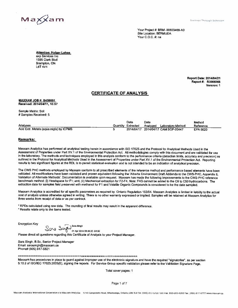


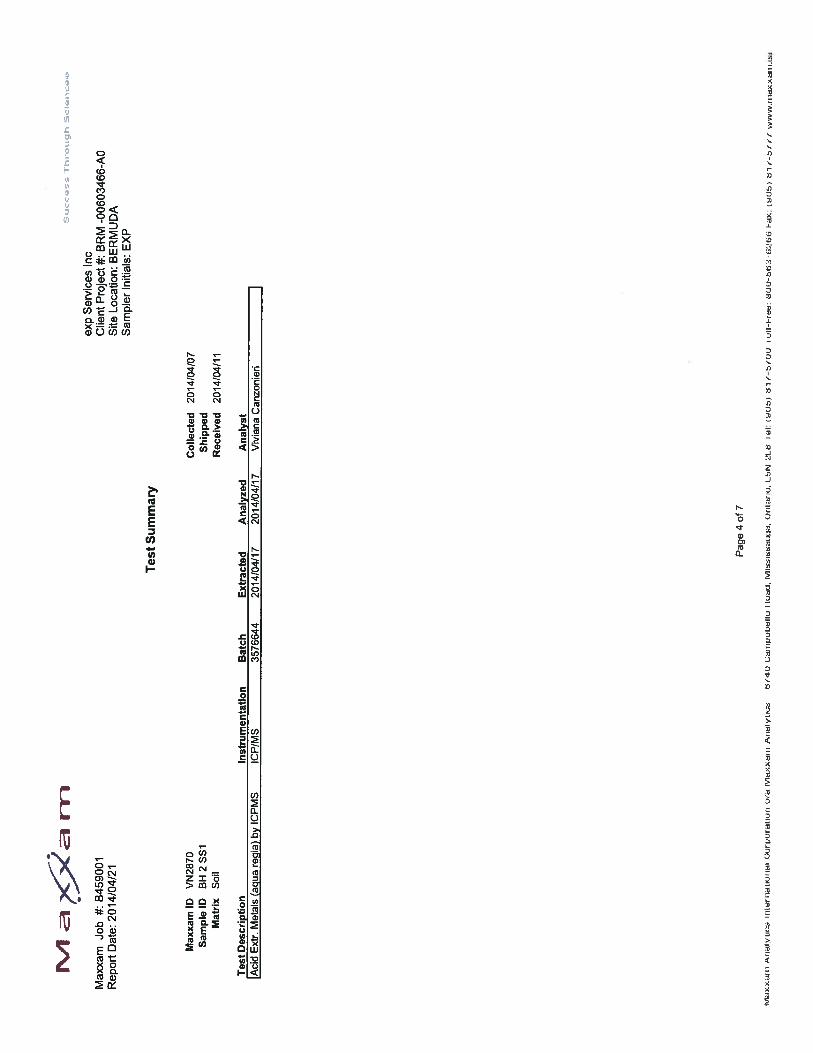


Brunell Ltd. Ltd. Geotechnical Investigation
Approaches to Bermuda BRM-00603466-A0
Appendix D: Gerhard Kuhn Thesis Reference Material