global specialist in electrical and digital building
TRANSCRIPT

Legrand_Catalogue 2014 01 Cover Page
THE GLOBAL SPECIALISTIN ELECTRICAL AND DIGITAL BUILDING INFRASTRUCTURES

Legrand_Catalogue 2014 Page 02
Introduction
Legrand, a clear, comprehensiveoffer for all types of application
DX3, a complete solution
2-3
4-5
6-7

Legrand_Catalogue 2014 Page 03
1
DX3, impeccable quality
Easy, safe connection
More comfort withenergy saving
Choose your distribution
Protection tailored to your requirements
Perfect control ofyour installation
Catalogue pages
10-11
8-9
16-17
15
14
12-13
18-73

Legrand_Catalogue 2014 Page 04
A company always known for its
groundbreaking innovations, Legrand’s
extensive R&D and technologically
advanced products make us who we
are today. As the global specialist in
electrical and digital building
infrastructures, our understanding of
the market and its needs motivate us to
innovate. Your recognition of our
efforts, led us to the next step - DX3.
2

Legrand_Catalogue 2014 Page 05
Presenting, DX3, an international
range of protection devices. Its
revolutionary design supports all
kinds of installations thus giving a
never before experience. With 10
patents, 13 new features and a
wide range, DX3 is the next step.
3
Legrand_Catalogue 2014 Page 06
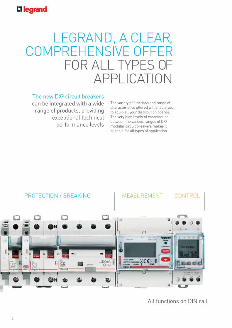
PROTECTION / BREAKING MEASUREMENT CONTROL
The variety of functions and range of characteristics offered will enable you to equip all your distribution boards. The very high levels of coordination between the various ranges of DX³ modular circuit breakers makes it suitable for all types of application.
All functions on DIN rail
The new DX³ circuit breakerscan be integrated with a widerange of products, providing
exceptional technicalperformance levels
LEGRAND, A CLEAR,COMPREHENSIVE OFFER
FOR ALL TYPES OFAPPLICATION
4

Legrand_Catalogue 2014 Page 07
Perfect complementarity for your distribution boards up to 6300 A and 100 kAbreaking capacity.
Each breakingcapacity has its ownpower solution
5

Legrand_Catalogue 2014 Page 08
The efficient designs of the products are such that they can be easily installed. The clear identification marks, to know the state of the circuit breaker, make it easier to maintain. The high quality products also assure the safety of the user, thus making it a complete solution.
DX3
A COMPLETESOLUTION
6

Legrand_Catalogue 2014 Page 09
New top clampfor all tools
Sliding shutters
Colour coded handlewith ON/OFFcolour indication
Improved air channels
Bottom clamp
Technicallabelling area
Integrated labelholder
Environment friendly
7
COPYTRACER, THE FIGHTAGAINST COUNTERFEITINGCopytracer is a unique registration numberthat is marked on some of our products.The number is stored in a database.Go to the website: www.legrand-copytracer.com

Legrand_Catalogue 2014 Page 10
The quality and hold of the connections are vital for the safety of distribution boards fitted with high breaking capacity MCBs. The connection areas are designed to make installation faster without compromising on safety.
Safety isprioritised with
the innovativefeatures of the
DX3 products
EASY, SAFE CONNECTION
8

Legrand_Catalogue 2014 Page 11
1.5modules/pole
RISING CLAMP TERMINALSEnsure a high quality, durableconnection
RELIABLE CONNECTIONSCompensation for the effect of looseningto ensure excellent hold over timeand consistent contact (In ≥ 80 A)
RETRACTABLE INSULATING SHIELDSWith the integrated retractable insulatingshields, no additional accessories areneeded to isolate the connectionson any breaking capacities and high ratingsof the 1.5 modules/pole (In ≤ 63 A) circuit breakers.
9
Black handle:circuit breakers
Grey handle: switches
Breaking capacity16 kA25 kA36 kA50 kA

Legrand_Catalogue 2014 Page 12
The design integrated with the DX3 range implicates its international quality. The products are crafted in a way to provide easeof installation.
Legrand pays particularattention to how these
devices perform:Each of them is set and
checked individuallyon the production lines
DX3
IMPECCABLE QUALITY
10

Legrand_Catalogue 2014 Page 13
ISI marking
Ergonomic test button
RoHS compliant
AC, A & HPI versions
Standard markingsTrip indicator
High safety terminals
Ergonomicred handle
AC22 A &10 kA ICs
Double breakmechanism
Improved relaydesign
11

Legrand_Catalogue 2014 Page 14
PERFECT CONTROL OF YOUR INSTALLATION
Auxiliary contacts and faultsignal contacts, shunt trips,undervoltage releases,overvoltage releases andmotorised controls.
The DX3 rangehas a selection
of electricalauxiliaries
for monitoringand controlling
circuits remotely
12

Legrand_Catalogue 2014 Page 15
DX3 motorised controls can be used with 1 module perpole devices (circuit breakers, RCBOs and RCCBs)just as easily as auxiliaries.
THE AUXILIARIES FIT FIRMLYwithout the need for any tools andensures that the entire assembly is robust
THE ACCESSIBILITY OF THE TERMINALSand the visibility of the screw heads makethe installer’s work easier
Legrand motorised controls are the most compactin the market: 1 module wide.They save a great deal of space inside thedistribution board.
OPTIMISED SPACE IN THE DISTRIBUTION BOARD
The colour code of the indicatorson the signalling auxiliaries isthe same as thatof the remote indicators
Marking of auxiliaries(characteristics,connection, mounting)
The fault signalcontacts have atest button
DX³ circuit breakers take upto 3 auxiliaries including onecontrol auxiliary
13

Legrand_Catalogue 2014 Page 16
PROTECTION TAILORED TO YOUR REQUIREMENTS
Trip indicator
Communication port
Measurement MeteringDisplay unit
Indicating lamp
Ergonomic test button Battery compartment
Navigation button
Di-electric test switch
The new DX³ RCD add-on modules with meteringhave a wide range of features to meet the moststringent safety requirements. They come withRS485 communication port for remote data viewer.
A compact solution forprotection and measurement
14

Legrand_Catalogue 2014 Page 17
EASY CONNECTION
CHOOSE YOUR DISTRIBUTION
Wiring and tedious tightening operationsare minimised, and the risks of poor contactand short-circuits are reduced, while mountingtime is optimised.
Legrand optimised distributionhas been designed for maximum
safety, ease of installation andmaintenance of distribution boards
OPTIMISED DISTRIBUTIONHX3 125 Ahorizontal distributionblocks with plug-inconnectionHorizontal 4-pole distribution for XL3
160 to 4000 enclosures:
- Optimised design: Freedom to mix 1P, 1P+N, 2P, 3P and 4P devices on the same row
- Optimised installation: Automatic connection with no wiring or clamping
- Safe connection and disconnection of devices, even when the distribution block is powered-up (due to the IP xxB insulation of the distribution block and the integral connection modules in the devices).
DISTRIBUTION BLOCKSUPPLY VIA THEPOWER SUPPLY MODULE PROVIDED
CONNECTION MODULESSet of 4 connection modules (L1, L2, L3, N)for 1 module/pole devices
DISTRIBUTIONBLOCK SUPPLYVIA THE MAINDEVICE
Circuit breakers with plug-in terminalsare fixed onto the distribution blockwith no need for any tool. The phaseto be connected is determined by thechoice of the connector. The distributionblock can be supplied via the powersupply module provided or via thehead of row device.
15

Legrand_Catalogue 2014 Page 18
MORE COMFORTWITH ENERGY SAVINGS
With its time switches & contactors,Legrand guarantees a unique experience.With the selection of functions available,it is simple to improve the safety, efficiencyand comfort of installations and meetenergy requirements.
The Legrand modularcontrol and monitoring
devices are aperfect addition to
the range of DX3
protection devices
16

Legrand_Catalogue 2014 Page 19
Battery replacement
Weekly switching view
Operating date & time
Programming menus
+/- buttons
Data key
Menu
Operating mode
Environment friendly
• Conform to IEC/EN 61095• Space for power supply busbar on top (up to 25 A)• Manual override for test and repair functions, carried out via the handle• Permanent "ON" or "OFF" without automatic reset
• With synchronous (mains- synchronised clock precision) or quartz motor • +/- 2.5 s/day clock precision (quartz motor)• 100 hour running reserve (quartz motor) • Surface-mounting possible with a wall bracket and a terminal cover (cat no : 412859)• Unit width: 3 modules of 17.5 mm each
17

18
P. 24DX³ - 25 kA MCB from 6 A to 125 A
P. 20-21DX³ - MCB AC Application upto 63 A
P. 27DX³ - Isolator AC Application upto 125 A
Isolator RCCB & RCBOs
P. 33CX³ Changeover switches
CX3 switches, push-buttons and indicators
P. 29DX³ - RCD add-on module for 125 A
RCD add-on module & Auxiliaries and other control functions
EMDX³ electricalenergy meters & measuring units
P. 34EMDX³electrical energymeters
MCBs
equipmentDIN RAIL
DX3
MCBs(p. 20)
DX3
Isolator(p. 27)
DISCOVER THE PRODUCTS

P. 25DX³ - 50 kA MCBs from 10 A to 63 A
P. 26DX³ - photovoltaic applications and RDSO
P. 25DX³ - 36 kA MCB from 10 A to 80 A
P. 22DX³ - MCB DC Application upto 63 A
P. 23DX³ - 16 kA MCB from 63 A to 125 A
P. 22DX³ - MCB AC Application from 80-125 A
P. 28DX³ - RCBOs AC Applicaiton upto 63 A
P. 29DX³ - RCBOs - 6 kA AC Applicaiton upto 32 A
P. 28DX³ - RCCBs AC Application from 80 - 100 A
P. 27DX³ - RCCBs AC Application upto 63 A
P. 33CX³ Push-buttons and control switches
P. 33CX³ LED indicators
P. 32Contactor
P. 31-32DX³ time switches
P. 31DX³ - RCD add-on module with measurement & metering
P. 30DX³ Auxiliaries
P. 34EMDX³ Multi-functions measuring units
P. 36Low voltage SPDs class I (T1)
P. 37Low voltage SPDs class II (T2)
P. 38SPDs for telephone lines
DX3 RCCB & RCBO(p. 27-29)
EMDX³multi-functionmesauring units(p. 34)

20Bold catalogue numbers are products normally available with Legrand (India) stockists. Cat.Nos that are not bold - delivery within 4 - 8 weeks from the date of order.
Bold packing quantity is our mandatory packing. Orders to be placed by Legrand (India) stockists in multiples of the same. Red catalogue numbers: New products
N
10 kA ISI marked as per IS/IEC 60898-1 2002 Integrated label holder Sliding bottom clamp Improved air channels Color coded On/Off indication on dolly Biconnect lower terminals IP 20 protected terminals Sliding shuttersDC-80 V per pole - 1 kA
Pack Cat.Nos DX3 MCBs - C curve
Single pole 240/415 VANominal rating In (A) Number of modules
1/10/120 4085 80 0.5 11/10/120 4085 81 1 11/10/120 4085 83 2 11/10/120 4085 84 3 11/10/120 4085 85 4 11/10/120 4085 87 6 11/10/120 4085 90 10 11/10/120 4085 92 16 11/10/120 4085 93 20 11/10/120 4085 94 25 11/10/120 4085 95 32 11/10/120 4085 96 40 11/10/120 4085 97 50 11/10/120 4085 98 63 1
Single pole + Neutral 230 VA1/5/60 4086 02 0.5 21/5/60 4086 03 1 21/5/60 4086 05 2 21/5/60 4086 06 3 21/5/60 4086 07 4 21/5/60 4086 09 6 21/5/60 4086 12 10 21/5/60 4086 14 16 21/5/60 4086 15 20 21/5/60 4086 16 25 21/5/60 4086 17 32 21/5/60 4086 18 40 21/5/60 4086 19 50 21/5/60 4086 20 63 2
2 pole 415 VA1/40 4086 21 0.5 21/40 4086 22 1 21/40 4086 24 2 21/40 4086 25 3 21/40 4086 26 4 21/40 4086 28 6 21/40 4086 31 10 21/40 4086 33 16 21/40 4086 34 20 21/40 4086 35 25 21/40 4086 36 32 21/40 4086 37 40 21/40 4086 38 50 21/40 4086 39 63 2
Pack Cat.Nos DX3 MCBs - C curve
3 pole 415 VANominal rating In (A) Number of modules
1/32 4086 43 0.5 31/32 4086 44 1 31/32 4086 46 2 31/32 4086 47 3 31/32 4086 48 4 31/32 4086 50 6 31/32 4086 53 10 31/32 4086 55 16 31/32 4086 56 20 31/32 4086 57 25 31/32 4086 58 32 31/32 4086 59 40 31/32 4086 60 50 31/32 4086 61 63 3
3 pole + Neutral 415 VA1/32 4086 65 0.5 41/32 4086 66 1 41/32 4086 68 2 41/32 4086 69 3 41/32 4086 70 4 41/32 4086 72 6 41/32 4086 75 10 41/32 4086 77 16 41/32 4086 78 20 41/32 4086 79 25 41/32 4086 80 32 41/32 4086 81 40 41/32 4086 82 50 41/32 4086 83 63 4
4 pole 415 VA1/32 4086 84 0.5 41/32 4086 85 1 41/32 4086 87 2 41/32 4086 88 3 41/32 4086 89 4 41/32 4086 91 6 41/32 4086 94 10 41/32 4086 96 16 41/32 4086 97 20 41/32 4086 98 25 41/32 4086 99 32 41/32 4087 00 40 41/32 4087 01 50 41/32 4087 02 63 4
4086 14 4086 37 4086 55 4086 77 4086 944085 90
Technical characteristics p. 39-53
DX3 MCBsMCBs for AC applications till 63 A

21Bold catalogue numbers are products normally available with Legrand (India) stockists. Cat.Nos that are not bold - delivery within 4 - 8 weeks from the date of order.
Bold packing quantity is our mandatory packing. Orders to be placed by Legrand (India) stockists in multiples of the same. Red catalogue numbers: New products
N
10 kA ISI marked as per IS/IEC 60898-1 2002 Integrated label holder Sliding bottom clamp Improved air channels Color coded On/Off indication on dolly Biconnect lower terminals IP 20 protected terminals Sliding shuttersDC-80 V per pole - 1 kA
Pack Cat.Nos DX3 MCBs - D curve
Single pole 240/415 VANominal rating In (A) Number of modules
1/10/120 4087 06 0.5 11/10/120 4087 07 1 11/10/120 4087 09 2 11/10/120 4087 10 3 11/10/120 4087 11 4 11/10/120 4087 12 6 11/10/120 4087 14 10 11/10/120 4087 16 16 11/10/120 4087 17 20 11/10/120 4087 18 25 11/10/120 4087 19 32 11/10/120 4087 20 40 11/10/120 4087 21 50 11/10/120 4087 22 63 1
Single pole + Neutral 230 VA1/5/60 4087 26 0.5 21/5/60 4087 27 1 21/5/60 4087 29 2 21/5/60 4087 30 3 21/5/60 4087 31 4 2
2 pole 415 VA1/40 4087 32 0.5 21/40 4087 33 1 21/40 4087 35 2 21/40 4087 36 3 21/40 4087 37 4 21/40 4087 38 6 21/40 4087 40 10 21/40 4087 42 16 21/40 4087 43 20 21/40 4087 44 25 21/40 4087 45 32 21/40 4087 46 40 21/40 4087 47 50 21/40 4087 48 63 2
Pack Cat.Nos DX3 MCBs - D curve
3 pole 415 VANominal rating In (A) Number of modules
1/32 4087 52 0.5 31/32 4087 53 1 31/32 4087 55 2 31/32 4087 56 3 31/32 4087 57 4 31/32 4087 58 6 31/32 4087 60 10 31/32 4087 62 16 31/32 4087 63 20 31/32 4087 64 25 31/32 4087 65 32 31/32 4087 66 40 31/32 4087 67 50 31/32 4087 68 63 3
3 pole + Neutral 415 VA1/32 4087 72 0.5 41/32 4087 73 1 41/32 4087 75 2 41/32 4087 76 3 41/32 4087 77 4 4
4 pole 415 VA1/32 4087 78 0.5 41/32 4087 79 1 41/32 4087 81 2 41/32 4087 82 3 41/32 4087 83 4 41/32 4087 84 6 41/32 4087 86 10 41/32 4087 88 16 41/32 4087 89 20 41/32 4087 90 25 41/32 4087 91 32 41/32 4087 92 40 41/32 4087 93 50 41/32 4087 94 63 4
4087 19 4087 46 4087 52 4087 90
Technical characteristics p. 39-53
DX3 MCBsMCBs for AC applications till 63 A (continued)

22Bold catalogue numbers are products normally available with Legrand (India) stockists. Cat.Nos that are not bold - delivery within 4 - 8 weeks from the date of order.
Bold packing quantity is our mandatory packing. Orders to be placed by Legrand (India) stockists in multiples of the same. Red catalogue numbers: New products
NN
10 kA as per IEC 60947-2Integrated label holderSliding insulating shieldColor coded contact indication windowIP 20 protected terminals50 sq mm terminals
Pack Cat.Nos DX3 MCBs 10 kA*
Single pole 230 VA / 400 VANominal rating In (A) Number of modules
1/5/160 4085 99 80 1.51/5/161 4086 00 100 1.51/5/162 4086 01 125 1.5
2 pole 400 VA1/5/60 4086 40 80 31/5/60 4086 41 100 31/5/60 4086 42 125 3
3 pole 400 VA1/9 4086 62 80 4.51/9 4086 63 100 4.51/9 4086 64 125 4.5
4 pole 400 VA1/9 4087 03 80 61/9 4087 04 100 61/9 4087 05 125 6
6 kA as per IEC 60947-2Integrated label holderSliding bottom clampImproved air channelsColor coded On/Off indication on dollyBiconnect lower terminalsIP 20 protected terminalsSliding shutters
Pack Cat.Nos DX3 MCBs 6 kA*
Single pole 250 V=Nominal rating In (A) Number of modules
1/10/120 4087 98 0.5 11/10/120 4087 99 1 11/10/120 4088 01 2 11/10/120 4088 02 3 11/10/120 4088 03 4 11/10/120 4088 04 6 11/10/120 4088 06 10 11/10/120 4088 08 16 11/10/120 4088 09 20 11/10/120 4088 10 25 11/10/120 4088 11 32 11/10/120 4088 12 40 11/10/120 4088 13 50 11/10/120 4088 14 63 1
2 pole 500 V=1/5/60 4088 15 0.5 21/5/60 4088 16 1 21/5/60 4088 18 2 21/5/60 4088 19 3 21/5/60 4088 20 4 21/5/60 4088 21 6 21/5/60 4088 23 10 21/5/60 4088 25 16 21/5/60 4088 26 20 21/5/60 4088 27 25 21/5/60 4088 28 32 21/5/60 4088 29 40 21/5/60 4088 30 50 21/5/60 4088 31 63 2
4086 00 4086 634086 40 4088 12
Technical characteristics p. 39-53
DX3 MCBsMCBs for AC applications 80 - 125 A
DX3 MCBsMCBs for DC applications 63 A
*For industrial use only.
*For industrial use only.

23Bold catalogue numbers are products normally available with Legrand (India) stockists. Cat.Nos that are not bold - delivery within 4 - 8 weeks from the date of order.
Bold packing quantity is our mandatory packing. Orders to be placed by Legrand (India) stockists in multiples of the same. Red catalogue numbers: New products
NDX3 MCBs - 16 kAthermal magnetic MCB from 6 A to 125 A
Breaking capacity 16 kA - IEC 60947-2 - 400 VACan be equipped with DX3 auxiliaries and accessories
Pack Cat.Nos DX3 MCBs 16 kA*
Single pole 230/400 V±Nominal rating In (A) Number of modules
1 4091 29 6 11 4091 31 10 11 4091 32 13 11 4091 33 16 11 4091 34 20 11 4091 35 25 11 4091 36 32 1.51 4091 37 40 1.51 4091 38 50 1.51 4091 39 63 1.51 4091 40 80 1.51 4091 41 100 1.51 4091 42 125 1.5
2 pole 230/400 V±1 4092 17 6 21 4092 19 10 21 4092 20 13 21 4092 21 16 21 4092 22 20 21 4092 23 25 21 4092 24 32 21 4092 25 40 31 4092 26 50 31 4092 27 63 31 4092 28 80 31 4092 29 100 31 4092 30 125 3
Pack Cat.Nos DX3 MCBs 16 kA*
3 pole 400 V±Nominal rating In (A) Number of modules
1 4092 69 6 31 4092 71 10 31 4092 72 13 31 4092 73 16 31 4092 74 20 31 4092 75 25 31 4092 76 32 4.51 4092 77 40 4.51 4092 78 50 4.51 4092 79 63 4.51 4092 80 80 4.51 4092 81 100 4.51 4092 82 125 4.5
4 pole 400 V±1 4093 51 6 41 4093 53 10 41 4093 54 13 41 4093 55 16 41 4093 56 20 41 4093 57 25 41 4093 58 32 61 4093 59 40 61 4093 60 50 61 4093 61 63 61 4093 62 80 61 4093 63 100 61 4093 64 125 6
4092 25
Technical characteristics p. 39-53
*For industrial use only. *For industrial use only.

24Bold catalogue numbers are products normally available with Legrand (India) stockists. Cat.Nos that are not bold - delivery within 4 - 8 weeks from the date of order.
Bold packing quantity is our mandatory packing. Orders to be placed by Legrand (India) stockists in multiples of the same. Red catalogue numbers: New products
N
Pack Cat.Nos DX3 MCBs - 25 kA*
Single pole 230/400 VAC curve Nominal rating In (A) Number of modules
1 4097 53 6 11 4097 54 10 11 4097 55 16 11 4097 56 20 11 4097 57 25 11 4097 58 32 1.51 4097 59 40 1.51 4097 60 50 1.51 4097 61 63 1.51 4097 62 80 1.51 4097 63 100 1.51 4097 64 125 1.5
2 pole - 230/400 V±1 4097 66 6 21 4097 67 10 21 4097 68 16 21 4097 69 20 21 4097 70 25 21 4097 71 32 21 4097 72 40 31 4097 73 50 31 4097 74 63 31 4097 75 80 31 4097 76 100 31 4097 77 125 3
Pack Cat.Nos DX3 MCBs - 25 kA* (continued)
3 pole - 400 V±C curve Nominal rating In (A) Number of modules
1 4097 79 6 31 4097 80 10 31 4097 81 16 31 4097 82 20 31 4097 83 25 31 4097 84 32 4.51 4097 85 40 4.51 4097 86 50 4.51 4097 87 63 4.51 4097 88 80 4.51 4097 89 100 4.51 4097 90 125 4.5
4 pole - 400 V±1 4097 92 6 41 4097 93 10 41 4097 94 16 41 4097 95 20 41 4097 96 25 41 4097 97 32 61 4097 98 40 61 4097 99 50 61 4098 00 63 61 4098 01 80 61 4098 02 100 61 4098 03 125 6
Breaking capacity: 25 kA - IEC 60947-2 - 400 VACan be equipped with DX3 auxiliaries and accessories
Technical characteristics p. 39-53
4097 72 4098 03
DX3 MCBs - 25 kAthermal magnetic MCBs from 6 A to 125 A
*For industrial use only. *For industrial use only.

25Bold catalogue numbers are products normally available with Legrand (India) stockists. Cat.Nos that are not bold - delivery within 4 - 8 weeks from the date of order.
Bold packing quantity is our mandatory packing. Orders to be placed by Legrand (India) stockists in multiples of the same. Red catalogue numbers: New products
NN
Breaking capacity: 36 kA - IEC 60947-2 - 400 VACan be equipped with DX3 auxiliaries and accessories
Breaking capacity: 50 kA - IEC 60947-2 - 400 VACan be equipped with DX3 auxiliaries and accessories
Pack Cat.Nos DX3 MCBs - 36 kA*
2 pole - 400 VAC curve Nominal rating In (A) Number of modules
1 4100 07 10 1.51 4100 08 16 1.51 4100 09 20 1.51 4100 10 25 1.51 4100 11 32 1.51 4100 12 40 1.51 4100 13 50 1.51 4100 14 63 1.51 4100 15 80 1.5
3 pole - 400 V±1 4100 20 10 4.51 4100 21 16 4.51 4100 22 20 4.51 4100 23 25 4.51 4100 24 32 4.51 4100 25 40 4.51 4100 26 50 4.51 4100 27 63 4.51 4100 28 80 4.5
4 pole - 400 V±1 4100 33 10 61 4100 34 16 61 4100 35 20 61 4100 36 25 61 4100 37 32 61 4100 38 40 61 4100 39 50 61 4100 40 63 61 4100 41 80 6
Pack Cat.Nos DX3 MCBs - 50 kA*
Single pole 230/400 VAD curve Nominal rating In (A) Number of modules
1 4101 34 10 1.51 4101 35 16 1.51 4101 36 20 1.51 4101 37 25 1.51 4101 38 32 1.51 4101 39 40 1.51 4101 40 50 1.51 4101 41 63 1.5
2 pole - 230/400 V±1 4101 47 10 31 4101 48 16 31 4101 49 20 31 4101 50 25 31 4101 51 32 31 4101 52 40 31 4101 53 50 31 4101 54 63 3
3 pole - 400 V±1 4101 60 10 4.51 4101 61 16 4.51 4101 62 20 4.51 4101 63 25 4.51 4101 64 32 4.51 4101 65 40 4.51 4101 66 50 4.51 4101 67 63 4.5
4 pole - 400 V±1 4101 73 10 61 4101 74 16 61 4101 75 20 61 4101 76 25 61 4101 77 32 61 4101 78 40 61 4101 79 50 61 4101 80 63 6
Technical characteristics p. 39-53 Technical characteristics p. 39-53
4100 12 4100 27 4101 51 4102 17
Violet marking = 50 kARed marking = 36 kA
*For industrial use only.
*For industrial use only.
DX3 MCBs - 36 kAthermal magnetic MCBs from 10 A to 80 A
DX3 MCBs - 50 kAthermal magnetic MCBs from 10 A to 63 A

26Bold catalogue numbers are products normally available with Legrand (India) stockists. Cat.Nos that are not bold - delivery within 4 - 8 weeks from the date of order.
Bold packing quantity is our mandatory packing. Orders to be placed by Legrand (India) stockists in multiples of the same. Red catalogue numbers: New products
NNDX3
for RDSO
DX3
for photovoltaic applications
4088 40
Pack Cat.Nos DC MCBs
Breaking capacity 4.5 kA according to EN 60947-2
800 V= circuit breakers1 4144 24 6 A 1 4144 25 8 A1 4144 26 10 A1 4144 27 13 A1 4144 28 16 A1 4144 29 20 A
1000 V= circuit breakers1 4144 46 10 A1 4144 47 13 A1 4144 48 16 A1 4144 49 20 A1 4144 50 25 A1 4144 51 32 A
Type 2 voltage surge protectorsDC side protection of photovoltaic installations connected to the low voltage network (without energy storage system) Conforming to UTE guide C 61-740-51Protection in common mode and residual current mode (Y mode) 1Consisting of plug-in modules with LED indicator Red: modules need to be replaced
Voltage surge protectors1 4141 60 600 V= 25 KA Imax1 4141 51 1000 V 40 KA Imax
Plug-in replacement module1 4141 90 +/- cassette
for voltage surge protector 4141 601 4141 91 T cassette
for voltage surge protector 4141 601 4141 81 +/- and T cassette
for voltage surge protector 4141 51
DC rotary handle isolating switchesCategory of use DC 21B according to EN 60947-3Double break contacts
600 V= isolating switches1 4142 61 16 A1 4142 62 25 A1 4142 63 32 A
1000 V= isolating switches1 4142 81 16 A1 4142 82 25 A1 4142 83 32 A
Accessories1 4063 05 Pole separation devider10 4063 07 Spacing unit 0.5 unit
Pack Cat.Nos RDSO1 4088 32 0.5 A1 4088 33 1 A1 4088 34 1.5 A1 4088 35 1.6 A1 4088 36 2.5 A1 4088 37 3 A1 4088 38 4 A1 4088 39 5 A1 4088 40 10 A1 4088 42 20 A1 4088 43 25 A1 4088 44 30 A1 4088 45 35 A1 4088 46 40 A1 4088 47 50 A 1 4088 48 60 A

27Bold catalogue numbers are products normally available with Legrand (India) stockists. Cat.Nos that are not bold - delivery within 4 - 8 weeks from the date of order.
Bold packing quantity is our mandatory packing. Orders to be placed by Legrand (India) stockists in multiples of the same. Red catalogue numbers: New products
NNDX3 RCCBsRCCBs for AC applications upto 63 A
DX3 isolatorsISs for AC applications upto 125 A
ISI marked as per IS 12640-1Integrated label holderErgonomic Grey color dollySliding bottom clampColor coded On/Off indication on dollyBiconnect lower terminalsIP 20 protected terminals35 sq mm terminalsSliding shutters
Pack Cat.Nos DX3 RCCBs
2 pole 240 VA30 mA
Nominal rating In (A) Number of modules1/5/60 4118 51 25 21/5/60 4118 52 40 21/5/60 4118 53 63 2
100 mA1/5/60 4118 56 25 21/5/60 4118 57 40 21/5/60 4118 58 63 2
300 mA1/5/60 4118 61 25 21/5/60 4118 62 40 21/5/60 4118 63 63 2
4 pole 415 VA30 mA
1/32 4118 76 25 41/32 4118 77 40 41/32 4118 78 63 4
100 mA1/32 4118 81 25 41/32 4118 82 40 41/32 4118 83 63 4
300 mA1/32 4118 86 25 41/32 4118 87 40 41/32 4118 88 63 4
4 pole 415 VA, A-S300 mA
1/5/60 4118 91 25 41/5/60 4118 92 40 41/5/60 4118 93 63 4
2 pole 240 VA, HPI 30 mA
1/5/60 4118 71 25 21/5/60 4118 72 40 21/5/60 4118 73 63 2
4 pole 415 VA, HPI
30 mA1/32 4118 96 25 41/32 4118 97 40 41/32 4118 98 63 4
Pack Cat.Nos Isolators
2 pole 415 VANominal rating In (A) Number of modules
1/5/60 4065 00 32 21/5/60 4065 01 40 21/5/60 4065 02 63 21/5/60 4065 04 100 21/5/60 4065 05 125 2
3 pole 415 VA1/40 4065 09 32 31/40 4065 10 40 31/40 4065 11 63 31/40 4065 13 100 31/40 4065 14 125 3
4 pole 415 VA1/32 4065 18 32 41/32 4065 19 40 41/32 4065 20 63 41/32 4065 22 100 41/32 4065 23 125 4
Isolators for AC applications upto 125 AISI marked as per IEC 60947-3Integrated label holderErgonomic red color dollySliding bottom clampDouble break mechanismImproved air channelsColor coded On/Off indication on dollyBiconnect lower terminalsIP 20 protected terminalsSliding shutters
4065 00 4065 20 4118 77 4118 934065 10 4118 51
Technical characteristics p. 53 Technical characteristics p. 54-59

28Bold catalogue numbers are products normally available with Legrand (India) stockists. Cat.Nos that are not bold - delivery within 4 - 8 weeks from the date of order.
Bold packing quantity is our mandatory packing. Orders to be placed by Legrand (India) stockists in multiples of the same. Red catalogue numbers: New products
NNDX3 RCCBsRCCBs for AC applications 80 - 100 A
DX3 RCBOsRCBOs assembled for AC applications upto 63 A
Pack Cat.Nos DX3 RCCBs*
2 pole 240 VA30 mA
Nominal rating In (A) Number of modules1/5/60 4115 07 80 2
100 mA1/5/60 4115 17 80 2
300 mA1/5/60 4115 27 80 2
4 pole 415 VA30 mA
1/32 4117 05 80 41/32 4117 63 100 4
100 mA1/32 4117 15 80 41/32 4117 73 100 4
300 mA1/32 4117 25 80 41/32 4117 83 100 4
2 pole 240 VA, HPI30 mA
1/5/60 4118 74 80 2
4 pole 415 VA, HPI30 mA
1/32 4118 99 80 4
4 pole 415 VA, A-S300 mA
1/5/60 4118 94 80 4
2 pole 230 VA, B type MDo not accept auxiliaries30 mA
1 4118 42 40 21 4118 43 63 2
300 mA1 4118 44 40 21 4118 45 63 2
4 pole 400 VA, neutral on left-hand side B type MDo not accept auxiliaries30 mA
1 4118 46 40 41 4118 47 63 4
300 mA1 4118 48 40 41 4118 49 63 4
Integrated label holderErgonomic Grey color dollyColor coded On/Off indication on dollyIP 20 protected terminals35 sq mm terminalsSliding shuttersB type M detect sinusoidal AC, pulsating DC and smooth DC residual currents
Pack Cat.Nos DX3 RCBOs
2 pole 240 VA, AC Type
30 mANominal rating In (A) Number of modules
1/32 4113 22 6 41/32 4113 23 10 41/32 4113 24 16 41/32 4113 25 25 41/32 4113 26 32 41/32 4113 27 40 41/32 4113 28 63 4
100 mA1/32 4113 29 6 41/32 4113 30 10 41/32 4113 31 16 41/32 4113 32 25 41/32 4113 33 32 41/32 4113 34 40 41/32 4113 35 63 4
300 mA1/32 4113 36 16 41/32 4113 37 25 41/32 4113 38 32 41/32 4113 39 40 41/32 4113 40 63 4
4 pole 415 VA, AC Type30 mA
1/16 4113 88 6 71/16 4113 89 10 71/16 4113 65 16 71/16 4113 66 25 71/16 4113 67 32 71/16 4113 68 40 71/16 4113 69 63 7
100 mA1/16 4113 70 16 71/16 4113 71 25 71/16 4113 72 32 71/16 4113 73 40 71/16 4113 74 63 7
300 mA1/16 4113 75 16 71/16 4113 76 25 71/16 4113 77 32 71/16 4113 78 40 71/16 4113 79 63 7
ISI marked as per IS 12640-2Integrated label holderErgonomic designColor coded On/Off indication on dollyFront face indication for earth leakage faultIP 20 protected terminals35 sq mm terminalsSliding shutters
4115 08 4117 05 4117 15 4113 794113 24
Technical characteristics p. 54-59 Technical characteristics p. 54-59
*For industrial use only.

29Bold catalogue numbers are products normally available with Legrand (India) stockists. Cat.Nos that are not bold - delivery within 4 - 8 weeks from the date of order.
Bold packing quantity is our mandatory packing. Orders to be placed by Legrand (India) stockists in multiples of the same. Red catalogue numbers: New products
NN
Pack Cat.Nos DX3 RCBOs, 2 pole 240 VAISI marked as per IEC 61009Integrated label holderErgonomic designColor coded On/Off indication on dollyFront face indication for earth leakage faultIP 20 protected terminals35 sq mm terminalsSliding shuttersAC Type30 mA
Nominal rating In (A) Number of modules1/32 4113 90 6 21/32 4113 91 10 21/32 4113 92 16 21/32 4113 93 20 21/32 4113 94 25 21/32 4113 95 32 2
300 mA1/32 4113 97 6 21/32 4113 98 10 21/32 4113 99 16 21/32 4114 00 20 21/32 4114 01 25 21/32 4114 02 32 2
HPI Type30 mA
1/32 4114 15 25 21/32 4114 16 32 2
DX3 RCBOs, 4 pole 415 VAComplies to per IEC 61009Integrated label holderErgonomic designColor coded On/Off indication on dollyFront face indication for earth leakage faultIP 20 protected terminals35 sq mm terminalsSliding shuttersAC Type
30 mANominal rating In (A) Number of modules
1/16 4111 85 10 41/16 4111 86 16 41/16 4111 87 20 41/16 4111 88 25 41/16 4111 89 32 4
300 mA1/16 4112 04 10 41/16 4112 05 16 41/16 4112 06 20 41/16 4112 07 25 41/16 4112 08 32 4
A Type
30 mA1/16 4112 33 10 41/16 4112 34 16 41/16 4112 35 20 41/16 4112 36 25 41/16 4112 37 32 4
300 mA1/16 4112 38 10 41/16 4112 39 16 41/16 4112 40 20 41/16 4112 41 25 41/16 4112 42 32 4
Pack Cat.Nos DX3 RCD
2 pole 240 VA, AC TypeNominal rating In (A) Number of modules
30 mA1 4105 68 125 A 4
100 mA1 4105 69 125 A 4
300 mA1 4105 71 125 A 4
4 pole 415 VA, AC Type30 mA
1 4106 25 125 A 4100 mA
1 4106 26 125 A 4300 mA
1 4106 29 125 A 4
2 pole 240 VA, HPI type30 mA
1 4105 78 125 A 6100 mA
1 4105 79 125 A 6300 mA
1 4105 82 125 A 6
Four pole 415 VA, HPI type30 mA
1 4106 38 125 A 6100 mA
1 4106 39 125 A 6300 mA
1 4106 42 125 A 6
Conform to IEC 60947-2AC type : detect AC components faultsHpi type :detect faults with AC and DC components, increasedImmunity to false trippingFor mounting on the right-hand side of 1.5 module per pole DX3 MCBsEasy & fast association mechanismTerminal cover for locking70 sq mm terminals
4113 94 4111 88 4112 08 4105 68 4105 78
Technical characteristics p. 54-59 Technical characteristics p. 54-59
DX3 RCBOsRCBOs compact for AC applications upto 32 A, 6 kA
DX3 RCD add on moduleFor 125 A

30Bold catalogue numbers are products normally available with Legrand (India) stockists. Cat.Nos that are not bold - delivery within 4 - 8 weeks from the date of order.
Bold packing quantity is our mandatory packing. Orders to be placed by Legrand (India) stockists in multiples of the same. Red catalogue numbers: New products
NN
Pack Cat.Nos Signalling auxiliariesNumber of modules
1 4062 50 Auxiliary changeover switch 6 A
0.5
1 4062 52 Fault signalling changeoverswitch 6 A
0.5
1 4062 64 Changeover + fault signalling switch
1
Control auxiliaries1 4062 76 Shunt release
12 /48 V AC/DC1
1 4062 78 Shunt release 110/415 V AC
1
1 4062 80 Undervoltage release 24/48 V AC/DC
1
1 4062 82 Undervoltage release 230 V AC
1
1 4062 86 Pop over voltage release 11 4062 90 Motor control
24/48 V AC/DC1
1 4062 91 Motor control 230 V AC
1
1 4062 93 Motor control auto reset 24/48 V AC/DC
2
1 4062 95 Motor control auto reset 230 V AC
2
1 4062 88 Automatic resetter 21 4062 89 Automatic resetter
with autotest2
Rotary handle10 4063 19 Black rotary
handle-
10 4063 20 Yellow/red rotary handle
-
Support for padlock10 4063 03 Support for
padlock till 63 A-
Sealable screw cover10 4063 04 Devices upto 63 A -10 4063 06 For 80-125 A devices -
1/2 module spacing unit10 4063 07 1/2 module
spacing unit0.5
5 mm padlock10 4063 13 1/2 module
spacing unit-
Easy & fast fixation on siteOn site clip on mountingClip on fitting on left side Pack Cat.Nos For 1 mod/pole MCBs and ISs
Number of modules5 4063 14 Manual change-over
switch for DP2
5 4063 15 Manual change-over switch for TP
3
5 4063 16 Manual change-over switch for FP
3
Compact designManual switching operationEasy to assembleErgonomic design
4062 50 4062 52 4062 78 4062 82
Technical characteristics p. 61
DX3 auxiliaries Auxiliaries common for MCBs, Isolators, RCCBs & RCBOs
DX3 auxiliariesManual changover switch

31Bold catalogue numbers are products normally available with Legrand (India) stockists. Cat.Nos that are not bold - delivery within 4 - 8 weeks from the date of order.
Bold packing quantity is our mandatory packing. Orders to be placed by Legrand (India) stockists in multiples of the same. Red catalogue numbers: New products
NN
Pack Cat.Nos Adjustable metering, 4 pole 415 VANominal rating In (A) Number of modules
1 4106 57 63 A 71 4106 58 125 A 7
Adjustable measurement1 4106 59 125 A 7
Conform to IEC 60947-2Hpi type: detect faults with AC and DC components, increasedImmunity to false trippingInbuilt measurement/metering optionMeasurement - V, A, F, PF, KWh, KVA, KVAr, THDMetering - V, A, F, KWhRS 485 port for remote readingDi-electric test button inbuiltErgonomic test buttonScroll button for easy readingsRLCD display on front faciaFor mounting on the right-hand side of 1.5 module per pole DX3 MCBsEasy & fast association mechanism70 sq mm terminals
Pack Cat.Nos Alpharex3 digital time switches1 4126 31 AlphaRex3 D21,
1 channel1 4126 41 AlphaRex3 D22,
2 channels1 4126 34 AlphaRex3 D21s,
1 channel, with control input
Alpharex3 digital time switches - Astro• For switching on/off lights and other electric devices according to the rising/setting of the
sun• With combination function for creating switching
programs in which the devices are switched according to astronomical time and/or fixed preset times
• Daily astronomical calculation of the sunrise/sunset times based on the entered location or location coordinates
1 4126 54 AlphaRex3 D21 astro, 1 channel
1 4126 57 AlphaRex3 D22 astro, 2 channels
Alpharex3 yearly time switch• Yearly and weekly time switch with additional
astronomical function for all channels• 84 switching programs per channel,
comprising:- 28 weekly programs- 28 yearly programs- 28 special programs (priority program)
1 4126 29 AlphaRex3 DY21, 1 channel
1 4126 30 AlphaRex3 DY22, 2 channels
Programming accessories1 4128 72 Data key1 4128 73 PC adapter for
USB port
Daily and weekly time switchQuick and easy programming due to the option toselect day blocks, day blocks can be individually setor selected from the blocks Mon–Sun, Mon–Fri or Sat–Sun Programming with precision to the secondSwitch times visible in weekly overview on display
4106 57 4126 41 4126 54 4126 57 4126 29
Technical characteristics p. 59 Technical characteristics p. 62-66
DX3 time switchesDX3 RCD add on module with measurement & metering
32Bold catalogue numbers are products normally available with Legrand (India) stockists. Cat.Nos that are not bold - delivery within 4 - 8 weeks from the date of order.
Bold packing quantity is our mandatory packing. Orders to be placed by Legrand (India) stockists in multiples of the same. Red catalogue numbers: New products
NN
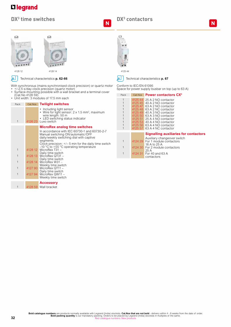
Pack Cat.Nos Twilight switches• Including light sensor• Wire for light sensor: 2 x 1.5 mm2, maximum
wire length: 50 m • LED switching status indicator
1 4126 23 Luxo switch
MicroRex analog time switchesIn accordance with IEC 60730-1 and 60730-2-7Manual switching ON/automatic/OFFdaily/weekly switching dial with captivesegments Clock precision: +/– 5 min for the daily time switch–10 °C to +55 °C operating temperature
1 4128 12 MicroRex T31 – Daily time switch
1 4128 13 MicroRex QT31 – Daily time switch
1 4128 14 MicroRex W31 – Weekly time switch
1 4127 90 MicroRex QT11 – Daily time switch
1 4127 94 MicroRex QW11 – Weekly time switch
Accessory1 4128 59 Wall bracket
With synchronous (mains-synchronised clock precision) or quartz motor• +/-2.5 s/day clock precision (quartz motor)• Surface-mounting possible with a wall bracket and a terminal cover
(Cat.No 4128 59)• Unit width: 3 modules of 17.5 mm each
Conform to IEC/EN 61095Space for power supply busbar on top (up to 63 A)
Pack Cat.Nos Power contactors CX3
1 4125 44 25 A 2 NO contactor1 4125 45 40 A 2 NO contactor1 4125 47 63 A 2 NO contactor1 4125 48 63 A 2 NC contactor1 4125 49 40 A 3 NO contactor1 4125 50 63 A 3 NO contactor1 4125 51 25 A 4 NO contactor1 4125 53 40 A 4 NO contactor1 4125 56 63 A 4 NO contactor1 4125 57 63 A 4 NC contactor
Signalling auxiliaries for contactorsAuxiliary changeover switch
1 4124 29 For 1 module contactors16 A to 25 A
1 4124 30 For 2 module contactors25 A
1 4124 31 For 40 and 63 Acontactors
4128 12 4128 14 4125 44
Technical characteristics p. 62-66 Technical characteristics p. 67
DX3 time switches DX3 contactors

33Bold catalogue numbers are products normally available with Legrand (India) stockists. Cat.Nos that are not bold - delivery within 4 - 8 weeks from the date of order.
Bold packing quantity is our mandatory packing. Orders to be placed by Legrand (India) stockists in multiples of the same. Red catalogue numbers: New products
N
4129 00 4129 084129 01 4129 164129 04 4129 12
Technical charcateristics p. 67
Pack Cat.Nos Changeover switches
Conform to IEC 60669-1 Nominal rating 32 ACompatible with fluorescent lamps (20 AX)
Two-way - 250 VAConnection
Number of modules
10 4129 00 1
Double two-way - 400 VA5 4129 01 2
Two way with centre point - 250 VA10 4129 02 1
Double two way with centre point - 250 VA5 4129 03 2
Switch NO + NC - 250 VA10 4129 04 1
Push-buttons and control switches
Conform to IEC 60669-1 Nominal rating 20 A - 250 VACompatible with florescent lamps (20 AX)Accept prong-type supply busbarsSingle function push-buttons
Connection Number of modules
10 4129 08 1 NO 1
10 4129 09 1 NC 1
Dual functions push-buttons without indicator
10 4129 16 1 NO (green push-button) + 1 NC (red push-button)
1
Single function control switches10 4129 10 2 NO 1
10 4129 11 1 NO + NC 1
Pack Cat.Nos Push-buttons and control switches (continued)Dual functions control switches with indicator
Connection Number of modules
10 4129 12 1 NO + green LED indicator 12/48 VA/=
1
10 4129 13 1 NC + red LED indicator 12/48 VA/=
1
10 4129 14 1 NO + green LED indicator 110/400 VA
1
10 4129 15 1 NC + red LED indicator 110/400 VA
1
LED indicators
Equipped with non replaceable LED lampsLED life: 100 000 hLED consumption: 0.17 W under 230 VA/ 0.11 W under 24 VA Conform to IEC 60947-5-1Accept prong-type supply busbars
Single - 12/48 VA/ =Connection
Number of modules
10 4129 21 Green 110 4129 22 Red 110 4129 23 Yellow 110 4129 24 Blue 110 4129 25 White 1
Single - 110/400 VA10 4129 26 Green 110 4129 27 Red 110 4129 28 Yellow 110 4129 29 Blue 110 4129 30 White 1
Double - 110/400 VA10 4129 31 Green/Red 1
Triple - 230/400 VA2 10 4129 32 White
N
110 4129 33 Red 110 4129 34 Red/Yellow/Green 1
10 4129 35 Red/Yellow/Blue 1
TX3 LED indicators - 250 VAEquipped with non replaceable LED lamps
SingleConnection
Number of modules
12 6040 77 Green 112 6040 78 Red 112 6040 79 Orange 1
4129 21 4129 31 4129 34 6040 78
CX3 changeover switches, push-buttons, control switches and LED indicators

34Bold catalogue numbers are products normally available with Legrand (India) stockists. Cat.Nos that are not bold - delivery within 4 - 8 weeks from the date of order.
Bold packing quantity is our mandatory packing. Orders to be placed by Legrand (India) stockists in multiples of the same. Red catalogue numbers: New products
NNEMDX3 multi-function measuring units4 rail mounting
EMDX3 electrical energy meters4 rail mounting
Pack Cat.Nos EMDX3 modular
For mounting on 2 railWidth: 4 modules• LCD display• Measurement of currents, voltages, active, reactive and apparent power and internal temperature• Dual tariff metering:- Active energy consumed- Reactive energy consumed- Operating time- Power factor• THD voltages and currents up to order 51• Programmable alarms on all functions• Outputs for controlling wiring devices, alarm feedback and pulse feedback
EMDX3 RS 485 unit1 0046 76 Data transmission via RS 485 communication
interface and pulses
Conform to standards:- IEC 61557-12- IEC 62053-22 class 0.5 S- IEC 62053-23 class 2
Pack Cat.Nos Single-phase meters
Direct connection1 0046 77 63 A - 2 modules
RS 485 output
Three-phase metersDirect connection
1 0046 80 63 A - 4 modulesRS 485 output
Connection with CT1 0046 84 5 A - 4 modules
RS 485 and pulse output
Measure the electricity consumed by a single-phase or three-phase circuit downstream of the electricity distribution meteringDisplay electricity consumption in kWh, as well as other values such as current, active energy, reactive energy and power (depending on the catalogue number)Conform to standards IEC 62053-21/23, IEC 62052-11 and IEC 61010-1MID compliance ensures accuracy of the metering with a view to recharging for the electricity used
Technical characteristics p. 68-69 Technical characteristics p. 68-69
0046 74 0046 76

35Bold catalogue numbers are products normally available with Legrand (India) stockists. Cat.Nos that are not bold - delivery within 4 - 8 weeks from the date of order.
Bold packing quantity is our mandatory packing. Orders to be placed by Legrand (India) stockists in multiples of the same. Red catalogue numbers: New products
Pack Cat.Nos Communication and supervision
1 0261 78 Web servers For 32 metering points (meters or multi-function measuring units)
1 0261 79 Web servers For an unlimited number of metering points (meters or multi-function measuring units)
1 0261 88 Legrand Software For 32 metering points (supplied on CD)
1 0261 89 Legrand Software For an unlimited number of metering points (supplied on CD)
1 0046 89 RS485/IP Convertor 230 V AC
Pack Cat.Nos Measurement and control of electric equipment
1/2 0261 35 Central position 1/3 0261 37 Microprocessor interface 1/2 0261 36 Interface signaling and control1/4 0261 45 Kit configurator
1/20 0466 23 Stabilized power
Technical characteristics p. 68-69 Technical characteristics p. 68-69
0261 37
EMDX3
measurement and control of electric equipment
EMDX3
communication and supervision
0261 78 0261 88/89
Multi-function measuring unit Cat.No 0046 76
Energy meters Cat.No 0046 84
RS 485 fieldbus
IP converter RS 485/IPCat.No 0046 88
EDMX3 Access multi-function measuring unit Cat.No 0146 68
+Communication module Cat.No 0146 71
EDMX3 Premium multi-function measuring unit Cat.No 0146 69
+Communication module Cat.No 0146 73
Legrand softwareCat.Nos 0261 88/89
IP protocol - Ethernet BUS
Web serverCat.Nos 0261 78/79
Measure Softwareunlimited

36Bold catalogue numbers are products normally available with Legrand (India) stockists.
Cat.Nos that are not bold - delivery within 4 - 8 weeks from the date of order. Bold packing quantity is our mandatory packing. Orders to be placed by Legrand (India) stockists in multiples of the same.
Protection against transient overvoltagess for 230/400 V± power networks (50/60 Hz). SPDs compliant with EN/IEC 61643-11 standardsRecommended for main distribution boardsClass I+II (T1+T2) : SPDs tested and specified according to both T1 and T2 test classes
Technical characteristics p. 70-72
Pack Cat.Nos SPDs for general protection of main distribution boardSPDs with plug-in modules and status indicators:- Green: SPD operational- Orange: plug-in modules to be replacedEarthing systems: TT, TNC, TNS
T1+T2 - Iimp 12,5 kA/poleFor general protection of big installations and protection of small installations with external lightning protection (LPS).Up: 1.5 kV - Imax: 60 kA/pole - Uc: 320 V±Recommended MCB: DX³ 63 A - C curve
Number of poles
Neutral position
Itotal (10/350)
Remote status
monitoring (FS contact)
Number of modules
1 4122 70 1P - 12.5 kA No 11 4122 761 1P+N Right 25 kA Yes 21 4122 71 2P - 25 kA No 21 4122 72 3P - 37.5 kA Yes 31 4122 771 3P+N Right 50 kA Yes 41 4122 73 4P - 50 kA No 4
T1+T2 - Iimp 8 kA/poleSPDs for small installations without external lightning protection (LPS)Up: 1.3 kV - Imax: 50 kA/pole - Uc: 320 V±Recommended MCB: DX³ 40 A - C curve
1 4122 50 1P - 8 kA No 11 4122 561 1P+N Right 16 kA No 21 4122 51 2P - 16 kA No 21 4122 52 3P - 25 kA No 31 4122 571 3P+N Right 25 kA No 41 4122 53 4P - 32 kA No 4
SPDs for high risk level installationsSPDs for big installations with external lightning protection (LPS) and for high risk level installations according to EN/IEC 62305 standards.
T1 - Iimp 50 kA/pole - 440V± (IT) - MonoblocUp: 2.5 kV - Uc: 440 V±Earthing systems: TT, TNC, TNS, ITRecommended MCCB: DPX³160 - 80 A
Number of poles Itotal (10/350)
Remote status monitoring
(FS contact)
Number of modules
1 0030 002 1P 50 kA No 2
Pack Cat.Nos SPDs for high risk level installations (continued)
T1 - Iimp 35 kA/pole - 440V± (IT) - Plug-inSPDs with plug-in modules and status indicators:- Green: SPD operational- Red: plug-in modules to be replacedUp: 2.5 kV - Uc: 440 V± Earthing systems: TT, TNC, TNS, ITRecommended MCCB: DPX³ 160 - 80 A
Number of poles
Neutral position
Itotal (10/350)
Remote status
monitoring (FS contact)
Number of modules
1 4122 80 1P - 35 kA Yes 2
T1 - Iimp 25 kA/poleSPDs with plug-in modules and status indicators:- Green: SPD operational- Red: plug-in modules to be replacedUp: 1.5 kV - Uc: 350 V± Earthing systems: TT, TNC, TNS.Recommended MCCB: DPX³ 160 - 80 A
1 4122 811 1P+N Right 50 kA Yes 41 4122 82 3P - 75 kA Yes 61 4122 831 3P+N Right 100 kA Yes 8
Replacement plug-in modules1 4123 02 For SPDs T1+T2 - 8 kA
Cat.Nos 4122 50/51/52/53/56/571 4123 03 For SPDs T1+T2 - 12.5 kA
Cat.Nos 4122 70/71/72/73/76/771 4122 84 For SPDs T1 - 25 kA
Cat.Nos 4122 81/82/83 and 0030 20/22/23/27
1 4122 85 N-PE module for SPDs T1 - 25 kACat.Nos 4122 81/83 and 0030 23
1 4122 86 For SPDs T1 - 35 kA Cat.No 4122 80
Cabling accessories1 4123 10 Ready to use cabling kit consisting of 5
conductors (including the earth conductor) Cross section :16 mm²Lenght : 40 cm For cabling SPDs in industrial enclosures (for EN/IEC 61439 compliance).
4122 75 4122 57 4122 83 4123 03 4122 84
1: 1P+N and 3P+N: L-N and N-PE protection modes (common and differential modes), the N pole being protected by encapsulated spark gaps. Also called sometimes 1+1 and 3+12: Replaced mid 2015 by Cat.No 4122 80
Class I (T1) low voltage SPDs

37Bold catalogue numbers are products normally available with Legrand (India) stockists.
Cat.Nos that are not bold - delivery within 4 - 8 weeks from the date of order. Bold packing quantity is our mandatory packing. Orders to be placed by Legrand (India) stockists in multiples of the same.
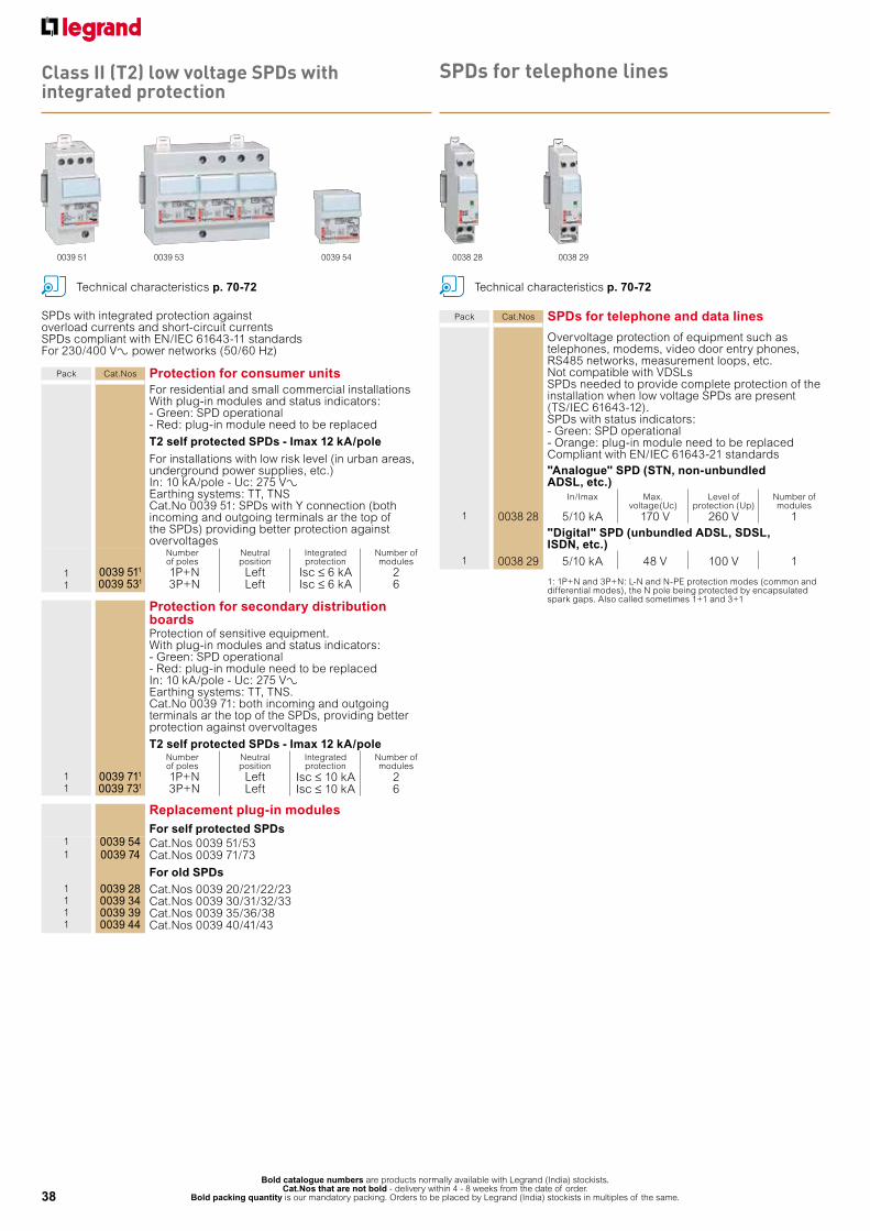
Class II (T2) low voltage SPDs
Protection against transient overvoltagess for 230/400 V± power networks (50/60 Hz). SPDs compliant with EN/IEC 61643-11 standardsRecommended for distribution boards
Technical characteristics p. 70-72
Pack Cat.Nos T2 add-on SPDs
SPDs with plug-in modules and status indicators:- Green: SPD operational- Orange: plug-in modules to be replacedSPDs providing increased safety during their lifetime and maintenance cycles. Prewired MCB connexions for increased reliability and for quick and easy Installation. To be equipped with DX3 MCBs (1 module/pole)Earthing systems: TT, TNS
T2 - Imax 40 kA/poleSPDs recommended for power installationsUp: 1.7 kV - In: 20 kA/pole - Uc: 320 V±Recommended MCB: DX³ 25 A - C curve
Number of poles
Neutral position
Remote status monitoring
(FS contact)
Number of modules
1 4122 661 1P+N Right Yes 41 4122 671 3P+N Right Yes 8
T2 - Imax 20 kA/poleSPDs recommended for small installations Up: 1.2 kV - In: 5 kA/pole - Uc: 320 V±Recommended MCB: DX³ 20A - C curve
1 4122 621 1P+N Right Yes 41 4122 631 3P+N Right Yes 8
Pack Cat.Nos T2 SPDs
SPDs with plug-in modules and status indicators:- Green: SPD operational- Orange: plug-in modules to be replaced
T2 - Imax 40 kA/poleSPDs recommended for power installationsUp: 1.7 kV - In: 20 kA/pole - Uc: 320 V±Earthing systems : TT, TNC, TNSRecommended MCB: DX³ 25 A - C curve
Number of poles
Neutral position
Remote status monitoring
(FS contact)
Number of modules
1 4122 40 1P - No 11 4122 461 1P+N Right No 21 4122 41 2P - No 21 4122 42 3P - Yes 31 4122 471 3P+N Right No 41 4122 43 4P - No 4
T2 - Imax 40 kA/pole - 440 V± (IT)SPDs recommended for big installationsUp: 2.1 kV - In: 20 kA/pole - Uc: 440 V±Earthing systems : TT, TNC, TNS, ITRecommended MCB: DX³ 25 A - C curve
1 4122 30 1P - No 11 4122 32 3P - Yes 31 4122 33 4P - Yes 4
T2 - Imax 20 kA/poleSPDs recommended for small installationsUp: 1.2 kV - In: 5 kA/pole - Uc: 320 V±Earthing systems : TT, TNC, TNSRecommended MCB: DX³ 20 A - C curve
1 4122 20 1P - No 11 4122 261 1P+N Right No 21 4122 21 2P - No 21 4122 271 3P+N Right No 41 4122 23 4P - No 4
Replacement plug-in modules1 4122 99 For SPDs T2 - 40 kA
Cat.Nos 4122 40/41/42/43/44/45/46/47/66/671 4123 00 N-PE module for SPDs T2 - 40 kA
Cat.Nos 4122 46/471 4123 01 For SPDs T2 - 440 V
Cat.Nos 4122 30/32/331 4122 97 For SPDs T2 - 20 kA
Cat.Nos 4122 20/21/23/26/27/62/631 4123 98 N-PE module for SPDs T2 - 20 kA
Cat.Nos 4122 24/25/26/27
4122 65 4122 67 4122 45 4122 99
1: 1P+N and 3P+N: L-N and N-PE protection modes (common and differential modes), the N pole being protected by encapsulated spark gaps. Also called sometimes 1+1 and 3+1
38Bold catalogue numbers are products normally available with Legrand (India) stockists.
Cat.Nos that are not bold - delivery within 4 - 8 weeks from the date of order. Bold packing quantity is our mandatory packing. Orders to be placed by Legrand (India) stockists in multiples of the same.
Class II (T2) low voltage SPDs with integrated protection
SPDs for telephone lines
1: 1P+N and 3P+N: L-N and N-PE protection modes (common and differential modes), the N pole being protected by encapsulated spark gaps. Also called sometimes 1+1 and 3+1
0038 28 0038 29
Pack Cat.Nos Protection for consumer unitsFor residential and small commercial installations With plug-in modules and status indicators: - Green: SPD operational - Red: plug-in module need to be replaced
T2 self protected SPDs - Imax 12 kA/poleFor installations with low risk level (in urban areas, underground power supplies, etc.)In: 10 kA/pole - Uc: 275 VAEarthing systems: TT, TNSCat.No 0039 51: SPDs with Y connection (both incoming and outgoing terminals ar the top of the SPDs) providing better protection against overvoltages
Number of poles
Neutral position
Integrated protection
Number of modules
1 0039 511 1P+N Left Isc ≤ 6 kA 21 0039 531 3P+N Left Isc ≤ 6 kA 6
Protection for secondary distribution boardsProtection of sensitive equipment.With plug-in modules and status indicators:- Green: SPD operational- Red: plug-in module need to be replacedIn: 10 kA/pole - Uc: 275 VAEarthing systems: TT, TNS.Cat.No 0039 71: both incoming and outgoing terminals ar the top of the SPDs, providing better protection against overvoltages
T2 self protected SPDs - Imax 12 kA/poleNumber of poles
Neutral position
Integrated protection
Number of modules
1 0039 711 1P+N Left Isc ≤ 10 kA 21 0039 731 3P+N Left Isc ≤ 10 kA 6
Replacement plug-in modulesFor self protected SPDs
1 0039 54 Cat.Nos 0039 51/531 0039 74 Cat.Nos 0039 71/73
For old SPDs1 0039 28 Cat.Nos 0039 20/21/22/231 0039 34 Cat.Nos 0039 30/31/32/331 0039 39 Cat.Nos 0039 35/36/381 0039 44 Cat.Nos 0039 40/41/43
Technical characteristics p. 70-72
Pack Cat.Nos SPDs for telephone and data lines
Overvoltage protection of equipment such as telephones, modems, video door entry phones, RS485 networks, measurement loops, etc. Not compatible with VDSLsSPDs needed to provide complete protection of the installation when low voltage SPDs are present (TS/IEC 61643-12).SPDs with status indicators:- Green: SPD operational- Orange: plug-in module need to be replacedCompliant with EN/IEC 61643-21 standards"Analogue" SPD (STN, non-unbundled ADSL, etc.)
In/Imax Max. voltage(Uc)
Level of protection (Up)
Number of modules
1 0038 28 5/10 kA 170 V 260 V 1"Digital" SPD (unbundled ADSL, SDSL, ISDN, etc.)
1 0038 29 5/10 kA 48 V 100 V 1
SPDs with integrated protection against overload currents and short-circuit currents SPDs compliant with EN/IEC 61643-11 standards For 230/400 VA power networks (50/60 Hz)
Technical characteristics p. 70-72
0039 51 0039 53 0039 54

39
DX3
MCBs
n Technical data
Specifications IS/IEC 60898-1 2002Number of poles SP, SPN, DP, TP, TPN, FPCharacteristics C & D CurveBreaking capacity 10 kA 0.5 A to 63 A as per IS/IEC 60898-1 2002
16 kA for 0.5 A to 25 A as per IEC 60947-2Rated voltage 230 V/400 VCurrent limitation class Class 3Frequency 50 Hz/60 HzMinimum operating voltage 12 V AC/DC Enclosures Polyester
self extinguishing, heat and fire resistant according to IEC 60898-1, glow-wire test at 960 °C for external parts made of insulating material necessary to retain in position current-carrying parts and parts of protective circuit (650 °C for all other external parts made of insulating material)
Mounting position Vertical / Horizontal / Upside down / On the sideFixing On symmetric rail EN/IEC 60715 or DIN 35Maximum cable size Top/Bottom 1 x 1.5 mm² to 35 mm²
Rigid cable 2 x 1.5 mm² to 16 mm²Top/Bottom 1 x 1.5 mm² to 25 mm²Flexible cable 2 x 1.5 mm² to 10 mm²
Applied connection torque Recommended : 2.5 Nm Minimum : 2 Nm Maximum: 3 Nm
Mechanical endurance 20000 operations without loadElectrical endurance 10000 operations with load (under In*cos j = 0.9)
2000 operations under In, DC currentPermissible ambient temperature 0.5 to 63A - Maximum + 70 0C Minimum -25 0C
Specifications IEC 60947-2Number of poles SP, DP, TP, FPBreaking capacity 10 kA 80 A to 125 A as per IEC 60898
16 kA for 80 A to 125 A as per IEC 60947-2Rated voltage 230 V/400 VCurrent limitation class Class 3Frequency 50 Hz/60 HzMinimum operating voltage 12 V AC/DC Enclosures Polyester
self extinguishing, heat and fire resistant according to IEC 60898-1, glow-wire test at 960 °C for external parts made of insulating material necessary to retain in position current-carrying parts and parts of protective circuit (650 °C for all other external parts made of insulating material)
Mounting position Vertical / Horizontal / Upside down / On the sideFixing On symmetric rail EN/IEC 60715 or DIN 35Maximum cable size Top/Bottom 1 x 1.5 mm² to 50 mm²
Rigid cable 2 x 1.5 mm² to 25 mm²Top/Bottom 1 x 1.5 mm² to 35 mm²Flexible cable 2 x 1.5 mm² to 20 mm²
Applied connection torque Recommended : 2.5 Nm Minimum : 2 Nm Maximum: 3 Nm
Mechanical endurance 20000 operations without loadElectrical endurance 10000 operations with load (under In*cos j = 0.9)
2000 operations under In, DC currentPermissible ambient temperature 80 to 125 A - Maximum + 70 0C Minimum -25 0C
Ambient Temperature / InIn (A) - 25 °C - 10 °C 0 °C 10 °C 20 °C 30 °C 40 °C 50 °C 60 °C 70 °C
0,5 0.62 0.6 0.57 0.55 0.52 0.5 0.47 0.42 0.40 0.381 1.5 1.4 1.3 1.2 1.1 1 0.9 0.8 0.7 0.62 2.8 2.6 2.5 2.3 2.2 2 2 1.9 1.8 1.73 3.8 3.6 3.5 3.3 3.2 3.0 2.9 2.8 2.7 2.64 4.5 4.2 4.0 3.9 3.7 3.5 3.4 3.3 3.2 3.15 6.4 6.0 5.8 5.5 5.3 5.0 4.8 4.7 4.5 4.66 7.5 7.0 6.6 6.4 6.2 6.0 5.8 5.6 5.4 5.310 12.5 11.5 11.1 10.7 10.3 10.0 9.7 9.3 9.0 8.716 20.0 18.7 18.0 17.3 16.6 16.0 15.4 14.7 14.1 13.520 25.0 23.2 22.4 21.6 20.8 20.0 19.2 18.4 17.6 16.825 31.5 29.5 28.3 27.2 26.0 25.0 24.0 22.7 21.7 20.732 41.0 37.8 36.5 34.9 33.3 32.0 30.7 29.1 27.8 26.540 51.0 48.0 46.0 44.0 42.0 40.0 38.0 36.0 34.0 32.050 64.0 60.0 57.5 55.0 52.5 50.0 47.5 45.0 42.5 40.063 80.6 75.6 72.5 69.9 66.1 63.0 59.8 56.1 52.9 49.7
Power dissipated in Watt per pole at InCircuit breakers C and D curves
Choice of DX3 MCBs for capacitor banksThis table shows the rated current of MCBs to be used when controlling capacitor banks so as to guarantee its function and shortcircuit protection. Overload protection is not necessary since these installations cannot be overloaded.This data refers to shortcircuit protection in absence of harmonics or heavy transitory currents.
Permitted limit as per 3 3 3 3 3 3 3 3 3.5 4.5 4.5 6 7.5 9 13 IEC 60898
In (A) 0,5 1 1,6 2 3 4 5 6 7,5 10 16 20 25 32 40 50 631P ÷ 4P 1.7 2 2 2 2 2 2.1 1.1 1.4 1.8 2 2.2 2.7 3.2 4 4.5 5.5
Impedance per pole (W) = P dissipated In2
DX3 MCB rating in amps C characteristic D characteristicPower of capacitor Single phase Three phase Single phase Three phasebank in kVAr 240 V 415 V 240 V 415 V 0.5 10 6 3 1 1 20 6 6 2 1.5 32 10 10 3 2.5 40 16 10 4 3 50 16 16 4 3.5 63 20 16 6 4 63 25 16 6 4.5 … 25 20 10 5 … 32 20 10 5.5 … 32 25 10 6 … 32 25 10 6.5 … 40 25 10 7 … 40 32 10 7.5 … 50 32 16 8 … 50 32 16 8.5 … 50 40 16 9 … 50 40 16 9.5 … 63 40 16 10 63 40 16 10.5 80 63 60 16 11 80 50 16 11.5 80 50 16 12 80 50 20 12.5 80 50 20 13 100 … 63 20 13.5 100 … 63 20 14 100 … 63 20 14.5 100 … 63 25 15 100 … 63 25 15.5 100 … 25 16 100 … 25 16.5 125 … … 25 17 125 … … 25 17.5 125 … … 25 18 125 … … 32 18.5 125 … … 32 19 125 … … 32 19.5 125 … … 32 20 125 … … 32 20.5 … … … 32 21 … … … 32 21.5 … … … 32 22 … … … 32 22.5 … … … 32 23 … … … 32 23.5 … … … 40 24 … … … 40 24.5 … … … 40 25 … … … 40 25.5 … … … 40 26 … … … 40 26.5 … … … 40 27 … … … 40 27.5 … … … 40 28 … … … 40 28.5 … … … 40 29 … … … 50 29.5 … … … 50 30 … … … 50 30.5 … 80 … 50 31 … 80 … 50 31.5 … 80 … 50 32 … 80 … 50 32.5 … 80 … 50 33 … 80 … 50 33.5 … 80 … 50 34 … 80 … 50 34.5 … 80 … 50 35 … 80 … 50 35.5 … 80 … 50 36 … 80 … 50 36.5 … 80 … 63 37 … 80 … 63 37.5 … 80 … 63 38 … 80 … 63 38.5 … 80 … 63 39 … 100 … 63 39.5 … 100 … 63 40 … 100 … 63 40.5 … 100 … 63 41 … 100 … 63 41.5 … 100 … 63 42 … 100 … 63 42.5 … 100 … 63 43 … 100 … 63 43.5 … 100 … 63 44 … 100 … 63 44.5 … 100 … 63 45 … 100 … 63 45.5 to 48 … 100 … … 48.5 to 60 … 125 … …

40
DX3
RDSO
n Technical data
Specification SPEC/E-12/1/14Number of poles 1Characteristic As applicableLine terminal Load terminal
Indicated by LNIndicated by LD
Rated Voltage 130 V=Max. Operating Voltage 440 V=Min. Operating Voltage 12 V =Voltage resistance > 2500 V±Enclosure Moulded out of DMC (thermoset plastic) bone grey colour, flamability class
V1-UL94, Tracking index - 600+voltsDolly Black, can be locked or lead sealed in ON or OFF positionFire retardent grade of enclosure VMounting position OptionalFixing Snap fixing on standard DIN RAIL profile EN 50023 - 35 x 7.5Terminals With flat Cu terminal extension mounting as per skel 3700. Current Carring
Capacity 100 Amp. Max. Continuous.On-Off indication MCB in on position when marking I-ON appears on dolly.
MCB in OFF position when making O-Off appears on dolly.Mech. Service Life 10000 operationElectrical Endurance 6000 operation at rated loadClimate resistance :Permissible Ambient :
25/95-40/93 ('C/RH) T max. - 45 0C, T min - 25 0C temperature
Shock resistance 20 g minimum 20 impacts duration of shock 13 ms.Vibration resistance 3 gAs per international STD, MCB in 'ON' condition when dolly is in upper position.

41
n Technical data
Correct polarity connections for DC MCBs
• Supply terminals
When supply is given at lower terminals
Single pole MCB Double pole MCB
• Supply terminalsWhen supply is given at upper terminals
Single pole MCB Double pole MCB
Derating of MCB for use with fluorescent lightsFerromagnetic and electronic ballasts have a high inrush current for a short time. These currents can cause the tripping of circuit breakers. At the time of the installation, it should take into account the maximum number of ballasts per circuit breaker that the manufacturers of lamps and ballasts indicate in their catalogues.
Influence of the altitude
Derating of MCBs function of the number of devices side by side:
When several MCBs are juxtaposed and operate simultaneously, the thermal evacuation of the poles is limited. This results in an increase in operating temperature of the circuit breakers which can cause unwanted tripping. It is recommended to apply the following coefficients to the rated currents.
Influence of the altitude
These values are given by the recommendation of IEC 60439-1, NF C 63421 and EN 60439-1 standards.
≤2000 m 3000 m 4000 m 5000 mDielectric holding 3000 V 2500 V 2000 V 1500 VMax operational voltage 400 V 400 V 400 V 400 VDerating at 30 °C none none none none
Number of circuit breakers side by side Coefficient2 - 3 0.94 - 5 0.86 - 9 0.7≥10 0.6
DX3 MCB Type Im1 Im2 Typical application0.5 A to 63 A D 10 In 20 In Protection of cable and appliance which has very high starting currents.6 A to 63 A C 5 In 10 In Protection of cable used for lighting load, power load and induction loads with high starting current.
lm1 - hold limitlm2 - Trip limit
Tripping characteristics
Standards has established different tripping characteristics depending on minimum and maximum values of magnetic trip.
Current limiting DX3 MCB Zero point extinguishing MCB
DX3 MCBs versus zero point extinguishing MCBs
Un = Mains VoltageUB = Arc Voltage ID = Let-through short circuit currentIP = Prospective short circuit current
DX3
MCBs

42
n Technical data
Association of protection devicesAssociation is the technique by which the breaking capacity of a MCB is increased by coordinating it with another protection device, placed upstream. This coordination makes it possible to use a protection device with a breaking capacity which is lower than the maximum prospective short-circuit current at its installation pointThe breaking capacity of a protection device must be at least equal to the maximum short-circuit which may occur at the point at which this device is installed.In exceptional cases, the breaking capacity may be lower than the maximum prospective short-circuit, as long as:• Itisassociatedwithadeviceupstreamwhichhasthenecessarybreaking capacity at its own installation point• Thedownstreamdeviceandthetrunkingbeingprotectedcanwithstand the power limited by the association of the devices. Association therefore leads to substantial savings.The association values given in the tables on the following pages are based on laboratory tests carried out in accordance with IEC 60947-2.
Note: In the case of single phase circuits (protected by P+N or 2P MCBs) in a 415 V AC supply, supplied upstream by a 3-phase circuit, it is advisable to use the association tables for 230 V.
Example of association
3-level associationAn association may be created on three levels if one of the conditions below is met.• The upstream device A must have an adequate breaking capacity at its installation point. Devices B and C are associated with device A. Simply check that the association values B+A and C+A have the necessary breaking capacity.In this case, there is no need to check the association between devices B and C.• The association is made between successive devices: Upstream device A, which has an adequate breaking capacity at its installation point, device C is associated with device B which is in turn associated with device A.Simply check that the association values C+B and B+A have the necessary breaking capacity. In this case, there is no need to check the association between devices A and C.
Association in IT connection systemsThe values given in the tables should only be used for TN and TT systems.Although this practice is not widely used, these values may also be used for installations with IT systems. It is therefore advisable to check that each protection device, on its own, can break, on a single pole, the maximum double fault current at the point in question.
DPX 250 ER 250 ABreaking capacity = 50 kA
Lexic MCB 40 A - C curveBreaking capacity alone = 10 kABreaking capacity in association with DPX 250 ER = 25 kA
Association between distribution boardsAssociation applies to devices installed in the same distribution board as well as in different boards. It is therefore generally possible to benefit from the advantages of the association between devices located, for example, in a main distribution board and in a secondary board.
MCB - switch associationThe switches must be systematically protected by an MCB placed upstream. There is considered to be protection against overloads if the rating of switch I is at least equal to that of the upstream MCB, D. If this is not the case, the thermal stresses (devices and conductors) must be checked. The tables on the following pages give the breaking capacity limits of the MCB - switch associations.
Table no 1
Table no 2
DX3
MCBs

43
Current discriminationThe discrimination is total for IscB
When the downstream MCB B is a limiting device, the short-circuit current is limited in terms of time and amplitude. The discrimination is therefore total if the limited current IscB, which device B allows to pass, is lower than the tripping current of device A
Time discriminationThis technique is based on the offset of the times of the tripping curves of the MCBs in series. It is checked by comparing the curves and is used for discrimination in the short-circuit zone. It is also used in addition to current discrimination in order to obtain discrimination beyond the magnetic setting current of the upstream MCB (ImA).
The following is necessary:• It must be possible to set a time delay on the upstream MCB• The upstream MCB must be able to withstand the short-circuit current and its effects for the whole period of the time delay • The trunking through which this current passes must be able to withstand the thermal stresses (I2t). The non-tripping time of the upstream
device must be longer than the breaking time (including any time delay) of the downstream device.DPX MCBs have a number of time delay setting positions for creating discrimination with a number of stages.
Discrimination of protection devices
Discrimination is a technique which consists of coordinating the protection in such a way that a fault on one circuit only trips the protection placed at the head of that circuit, thus avoiding rendering the remainder of the installation inoperative. Discrimination improves continuity of service and safety of the installationDiscrimination rules are set by the regulations concerning public buildings and for safety installations in general.
Discrimination between A and B is said to be “total” if it is provided up to the value of the maximum prospective short-circuit at the point at which B is installed.By extension, in the tables on the following pages, total discrimination, indicated by T, means that there is discrimination up to the breaking capacity of device B. Discrimination between A and B is said to be “partial” in the other cases.
The discrimination limit (given in the following tables) is therefore defined. This gives the short-circuit current value below which only MCB B will open and above which MCB A will also open.There are a number of techniques for providing discrimination:• Current discrimination, used for terminal circuits which have low short-circuits.• Time discrimination, provided by a delay on tripping the upstream MCB• Logical discrimination, a variant of time discrimination, used on electronic MCBs via a special link between the devices.
Since almost all faults occur during use, partial discrimination may be adequate if the discrimination limit is higher than the value of the maximum short-circuit which may occur at the point of use (or at the end of the trunking). This is referred to as “operating discrimination“. This technique is very often adequate, more economical and less restricting in terms of implementation.The discrimination limit for the association DPX 250 ER (160 A) with Lexic MCB 40 A (C curve) is 6 kA. Since the prospective ISC at the point of installation is 8 kA, the discrimination is not total. However, there is discrimination at the point of use at which the prospective short-circuit is only 3 kA.
Current discriminationThis technique is based on the off set of the intensity of the tripping curves of the upstream and downstream MCBs. It is checked by comparing these curves and checking that they do not overlap. It applies for the overload zone and the short-circuit zone, and the further apart the ratings of the devices, the better the discrimination.• On overloads To have discrimination in the overload zone, the ratio of the setting currents (Ir) must be at least 2. • On short-circuits To have discrimination in the short circuit zone, the ratio of the magnetic setting currents (Im) must be at least 1.5. The discrimination limit is then equal to the magnetic release current ImA of the upstream MCB. The discrimination is then total as long as IscB is less than ImA. Current discrimination is therefore very suitable for terminal circuits where the short-circuits are relatively weak. In other cases, time discrimination may be used together with current discrimination.
DPX 250 ER160 A
Lexic MCB 40 A
DX3
MCBs

44
DX3
MCBs
n Technical data
Coordination between Modular Circuit-Breakers and fuses, three-phase network (+ neutal) 400 / 415 V± according to standard IEC/EN 60947-2:
For TT or TN neutral system in 240/415 V network, to know the breaking capacity of the combination of a double pole breaker (connected between phase and neutral under 230 V) downstream of a triple-pole circuit-breaker, take the values shown in Tables 230/400 V.
All these values are also valid for circuit breakers associated to differential blocks.According to the curves and ratings of circuit breakers, attention to the threshold and size of upstream fuse which must necessarily be higher.
All these values are also valid for circuit breakers associated to RCD add-on modules.According to the curves and ratings of circuit breakers, attention to the magnetic threshold and to the size of upstream circuit breakers which must necessarily be higher.
Fuse upstreamgG Type
MCB downstream ≤20 A 25 A 32 A 40 A 50 A 63 A 80 A 100 A 125 A 160 A
DX3 10000 A/10 kAC and D curves
≤6 A 100 kA 100 kA 100 kA 100 kA 100 kA 100 kA 100 kA 100 kA 100 kA 40 kA10 A 100 kA 100 kA 100 kA 100 kA 100 kA 100 kA 100 kA 100 kA 100 kA 40 kA16 A - 100 kA 100 kA 100 kA 100 kA 100 kA 100 kA 100 kA 100 kA 40 kA20 A - - 100 kA 100 kA 100 kA 100 kA 100 kA 100 kA 100 kA 40 kA25 A - - - 100 kA 100 kA 100 kA 100 kA 100 kA 100 kA 40 kA32 A - - - - 100 kA 100 kA 100 kA 100 kA 100 kA 40 kA40 A - - - - - 100 kA 100 kA 100 kA 100 kA 40 kA50 A - - - - - - 100 kA 100 kA 100 kA 40 kA63 A - - - - - - 100 kA 100 kA 100 kA 40 kA
Fuse upstreamaM Type
MCB downstream ≤20 A 25 A 32 A 40 A 50 A 63 A 80 A 100 A 125 A 160 A
DX3 10000 A/10 kA C and D curves
≤6 A 100 kA 100 kA 100 kA 100 kA 100 kA 100 kA 100 kA 100 kA 100 kA 40 kA10 A 100 kA 100 kA 100 kA 100 kA 100 kA 100 kA 100 kA 100 kA 100 kA 40 kA16 A - 100 kA 100 kA 100 kA 100 kA 100 kA 100 kA 100 kA 100 kA 40 kA20 A - - 100 kA 100 kA 100 kA 100 kA 100 kA 100 kA 100 kA 40 kA25 A - - - 100 kA 100 kA 100 kA 100 kA 100 kA 100 kA 40 kA32 A - - - - 100 kA 100 kA 100 kA 100 kA 100 kA 40 kA40 A - - - - - 100 kA 100 kA 100 kA 100 kA 40 kA50 A - - - - - - 100 kA 100 kA 100 kA 40 kA63 A - - - - - - 100 kA 100 kA 100 kA 40 kA
Coordination between Modular Circuit-Breakers, three-phase network (+ neutal) 400 / 415 V± according to IEC/EN 60947-2:
For TT or TN neutral system in 230/400 V network, to know the breaking capacity of the combination of a double pole breaker (connected between phase and neutral under 230 V) downstream of a triple-pole circuit-breaker, take the values shown in Tables 230/400 V.
MCB upstreamDX3 10000/16 kAC and D Curves
MCB downstream ≤25 A 32 A 40 A 50 A 63 A 80 A 100 A 125 A
DX3 10000 AC Curves
≤6 A 16 kA 16 kA 16 A 16 kA 16 kA 16 kA 16 kA 16 kA10 A 16 kA 16 kA 16 kA 16 kA 16 kA 16 kA 16 kA 16 kA16 A 16 kA 16 kA 16 kA 16 kA 16 kA 16 kA 16 kA 16 kA20 A 16 kA 16 kA 16 kA 16 kA 16 kA 16 kA 16 kA 16 kA25 A - 16 kA 16 kA 16 kA 16 kA 16 kA 16 kA 16 kA32 A - - 16 kA 16 kA 16 kA 16 kA 16 kA 16 kA40 A - - - 16 kA 16 kA 16 kA 16 kA 16 kA50 A - - - - 16 kA 16 kA 16 kA 16 kA63 A - - - - - 16 kA 16 kA 16 kA
MCB upstreamDX3 25 kA
C and D CurvesMCB downstream ≤25 A 32 A 40 A 50 A 63 A 80 A 100 A 125 A
DX3 10000 AC Curves
≤6 A 25 kA 25 kA 25 kA 25 kA 25 kA 25 kA 25 kA 25 kA10 A 25 kA 25 kA 25 kA 25 kA 25 kA 25 kA 25 kA 25 kA16 A 25 kA 25 kA 25 kA 25 kA 25 kA 25 kA 25 kA 25 kA20 A 25 kA 25 kA 25 kA 25 kA 25 kA 25 kA 25 kA 25 kA25 A - 25 kA 25 kA 25 kA 25 kA 25 kA 25 kA 25 kA32 A - - 25 kA 25 kA 25 kA 25 kA 25 kA 25 kA40 A - - - 25 kA 25 kA 25 kA 25 kA 25 kA50 A - - - - 25 kA 25 kA 25 kA 25 kA63 A - - - - - 25 kA 25 kA 25 kA

45
n Technical data
Coordination between Modular Circuit-Breakers, three-phase network (+ neutal) 400/415 V± according to IEC/EN 60947-2:
For TT or TN neutral system in 240/415 V network, to know the breaking capacity of the combination of a double pole breaker (connected between phase and neutral under 230 V) downstream of a triple-pole circuit-breaker, take the values shown in Tables 240/415 V.
Coordination between Modular Circuit-Breakers (MCB) and Moulded Case Circuit Breakers (MCCBs), three-phase network (+ neutal) 400 / 415 V± according to standard IEC/EN60947-2:
For TT or TN neutral system in 240/415 V network, to know the breaking capacity of the combination of a double pole breaker (connected between phase and neutral under 230 V) downstream of a triple-pole circuit-breaker, take the values shown in Tables 240/415 V.
All these values are also valid for circuit breakers associated to RCD add-on modules.According to the curves and ratings of circuit breakers, attention to the magnetic threshold and to the size of upstream circuit breakers which must necessarily be higher.
All these values are also valid for circuit breakers associated to differential blocks.According to the curves and ratings of circuit breakers, attention to the magnetic threshold and to the size of upstream circuit breakers which must necessarily be higher.
MCB upstreamDX3 36 kA DX3 50 kAC Curve C and D Curves
MCB downstream ≤25 A 32 A 40 A 50 A 63 A 80 A ≤25 A 32 A 40 A 50 A 63 A
DX3 10000 AC Curves
≤6 A 36 kA 36 kA 36 kA 36 kA 36 kA 36 kA 50 kA 50 kA 50 kA 50 kA 50 kA10 A 36 kA 36 kA 36 kA 36 kA 36 kA 36 kA 50 kA 50 kA 50 kA 50 kA 50 kA16 A 36 kA 36 kA 36 kA 36 kA 36 kA 36 kA 50 kA 50 kA 50 kA 50 kA 50 kA20 A 36 kA 36 kA 36 kA 36 kA 36 kA 36 kA 50 kA 50 kA 50 kA 50 kA 50 kA25 A - 36 kA 36 kA 36 kA 36 kA 36 kA - 50 kA 50 kA 50 kA 50 kA32 A - - 36 kA 36 kA 36 kA 36 kA - - 50 kA 50 kA 50 kA40 A - - - 36 kA 36 kA 36 kA - - - 50 kA 50 kA50 A - - - - 36 kA 36 kA - - - - 50 kA63 A - - - - - 36 kA - - - - -
MCCB upstreamDPX3 160 / DPX3 160 + RCD
16 kAMCB downstream 16 A 25 A 40 A 63 A 80 A 100 A 125 A 160 A
DX3 10000 A/10 kAC and D curves
≤6 A 16 kA 16 kA 16 kA 16 kA 16 kA 16 kA 16 kA 16 kA10 A 16 kA 16 kA 16 kA 16 kA 16 kA 16 kA 16 kA 16 kA16 A - 16 kA 16 kA 16 kA 16 kA 16 kA 16 kA 16 kA20 A - 16 kA 16 kA 16 kA 16 kA 16 kA 16 kA 16 kA25 A - - 16 kA 16 kA 16 kA 16 kA 16 kA 16 kA32 A - - 16 kA 16 kA 16 kA 16 kA 16 kA 16 kA40 A - - - 16 kA 16 kA 16 kA 16 kA 16 kA50 A - - - 16 kA 16 kA 16 kA 16 kA 16 kA63 A - - - - 16 kA 16 kA 16 kA 16 kA
MCCB upstreamDPX3 160 / DPX3 160 + RCD
25 – 36 - 50 kAMCB downstream 16 A 25 A 40 A 63 A 80 A 100 A 125 A 160 A
DX3 10000 A/10 kAC and D curves
≤6A 25 kA 25 kA 25 kA 25 kA 25 kA 25 kA 25 kA 25 kA10A 25 kA 25 kA 25 kA 25 kA 25 kA 25 kA 25 kA 25 kA16A - 25 kA 25 kA 25 kA 25 kA 25 kA 25 kA 25 kA20A - 25 kA 25 kA 25 kA 25 kA 25 kA 25 kA 36 kA25A - - 25 kA 25 kA 25 kA 25 kA 25 kA 25 kA32A - - 25 kA 25 kA 25 kA 25 kA 25 kA 25 kA40A - - - 25 kA 25 kA 25 kA 25 kA 25 kA50A - - - 25 kA 25 kA 25 kA 25 kA 25 kA63A - - - - 25 kA 25 kA 25 kA 25 kA
DX3
MCBs

46
Coordination between Modular Circuit-Breakers (MCB) and Moulded Case Circuit Breakers (MCCBs), three-phase network (+ neutal) 400 / 415 V± according to standard IEC/EN60947-2:
For TT or TN neutral system in 240/415 V network, to know the breaking capacity of the combination of a double pole breaker (connected between phase and neutral under 230 V) downstream of a triple-pole circuit-breaker, take the values shown in Tables 240/415 V.
Coordination between Modular Circuit-Breakers and fuses, three-phase network (+ neutal) 230/240 V± according to standard IEC/EN 60947-2:
All these values are also valid for circuit breakers associated to differential blocks.According to the curves and ratings of circuit breakers, attention to the magnetic (or electronic) threshold and to the size of upstream circuit breakers which must necessarily be higher.
All these values are also valid for circuit breakers associated to differential blocks.According to the curves and ratings of circuit breakers, attention to the magnetic (or electronic) threshold and to the size of upstream circuit breakers which must necessarily be higher.
All these values are also valid for circuit breakers associated to differential blocks.According to the curves and ratings of circuit breakers, attention to the threshold and to the size of upstream fuses which must necessarily be higher.
MCCB upstreamDPX3 250 / DPX3 250+RCD
(Thermal-Magnetic & Electronic)25 - 36 - 50 kA - 70 kA
MCB downstream 100A 160A 200A 250A
DX3 10000 A/10 kAC and D curves
≤6 A 25 kA 25 kA 25 kA 25 kA10 A 25 kA 25 kA 25 kA 25 kA16 A 25 kA 25 kA 25 kA 25 kA20 A 25 kA 25 kA 25 kA 25 kA25 A 25 kA 25 kA 25 kA 25 kA32 A 25 kA 25 kA 25 kA 25 kA40 A 25 kA 25 kA 25 kA 25 kA50 A 25 kA 25 kA 25 kA 25 kA63 A 25 kA 25 kA 25 kA 25 kA
MCCB upstreamDPX / H / L 250
(Thermal-Magnetic & electronic) DPX 400AB DPX / DPXH / DPXL 630(Thermal-Magnetic & electronic)
36 - 70 - 100 kA 36 kA 36 - 70 - 100 kAMCB downstream 25A 40A 63A 100A 160A 250A 320A 400A 250A 320A 400A 500A 630A
DX3 10000 A/10 kAC and D curves
≤6 A 25 kA 25 kA 25 kA 25 kA 25 kA 25 kA 25 kA 25 kA 25 kA 25 kA 25 kA 25 kA 25 kA10 A 25 kA 25 kA 25 kA 25 kA 25 kA 25 kA 25 kA 25 kA 25 kA 25 kA 25 kA 25 kA 25 kA16 A 25 kA 25 kA 25 kA 25 kA 25 kA 25 kA 25 kA 25 kA 25 kA 25 kA 25 kA 25 kA 25 kA20 A 25 kA 25 kA 25 kA 25 kA 25 kA 25 kA 25 kA 25 kA 25 kA 25 kA 25 kA 25 kA 25 kA25 A - 25 kA 25 kA 25 kA 25 kA 25 kA 25 kA 25 kA 25 kA 25 kA 25 kA 25 kA 25 kA32 A - 25 kA 25 kA 25 kA 25 kA 25 kA 25 kA 25 kA 25 kA 25 kA 25 kA 25 kA 25 kA40 A - - 25 kA 25 kA 25 kA 25 kA 20 kA 20 kA 20 kA 20 kA 20 kA 20 kA 20 kA50 A - - 25 kA 25 kA 25 kA 25 kA 20 kA 20 kA 20 kA 20 kA 20 kA 20 kA 20 kA63 A - - - 20 kA 20 kA 20 kA 20 kA 20 kA 20 kA 20 kA 20 kA 20 kA 20 kA
MCCB upstreamDPX / H / L 1250
(Thermo-Magnetic)
DPX / H 1600(Electronic)
50 - 70 - 100 kA 36 - 70 kAMCB downstream 500 to 1250A 630 to 1600A
DX3 10000 A/10 kAC and D curves
≤6 A 25 kA 25 kA10 A 25 kA 25 kA16 A 25 kA 25 kA20 A 25 kA 25 kA25 A 20 kA 20 kA32 A 16 kA 16 kA40 A 16 kA 16 kA50 A 16 kA 16 kA63 A 16 kA 16 kA
Fuse upstreamgG Type
MCB downstream ≤20 A 25 A 32 A 40 A 50 A 63 A 80 A 100 A 125 A 160 A
DX3 10000 A/10 kAC and D curves
≤6 A 100 kA 100 kA 100 kA 100 kA 100 kA 100 kA 100 kA 100 kA 100 kA 40 kA10 A 100 kA 100 kA 100 kA 100 kA 100 kA 100 kA 100 kA 100 kA 100 kA 40 kA16 A - 100 kA 100 kA 100 kA 100 kA 100 kA 100 kA 100 kA 100 kA 40 kA20 A - - 100 kA 100 kA 100 kA 100 kA 100 kA 100 kA 100 kA 40 kA25 A - - - 100 kA 100 kA 100 kA 100 kA 100 kA 100 kA 40 kA32 A - - - - 100 kA 100 kA 100 kA 100 kA 100 kA 40 kA40 A - - - - - 100 kA 100 kA 100 kA 100 kA 40 kA50 A - - - - - - 100 kA 100 kA 100 kA 40 kA63 A - - - - - - 100 kA 100 kA 100 kA 40 kA
Fuse upstreamaM Type
MCB downstream ≤20 A 25 A 32 A 40 A 50 A 63 A 80 A 100 A 125 A 160 A
DX3 10000 A/10 kAC and D curves
≤6 A 100 kA 100 kA 100 kA 100 kA 100 kA 100 kA 100 kA 100 kA 100 kA 40 kA10 A 100 kA 100 kA 100 kA 100 kA 100 kA 100 kA 100 kA 100 kA 100 kA 40 kA16 A - 100 kA 100 kA 100 kA 100 kA 100 kA 100 kA 100 kA 100 kA 40 kA20 A - - 100 kA 100 kA 100 kA 100 kA 100 kA 100 kA 100 kA 40 kA25 A - - - 100 kA 100 kA 100 kA 100 kA 100 kA 100 kA 40 kA32 A - - - - 100 kA 100 kA 100 kA 100 kA 100 kA 40 kA40 A - - - - - 100 kA 100 kA 100 kA 100 kA 40 kA50 A - - - - - - 100 kA 100 kA 100 kA 40 kA63 A - - - - - - 100 kA 100 kA 100 kA 40 kA
n Technical data
DX3
MCBs

47
Coordination between modular circuit-breakers, three-phase network (+ neutal) 230/240 V± according to IEC/EN 60947-2:
Coordination between Modular Circuit-Breakers, three-phase network (+ neutal) 230/240 V± according to IEC/EN 60947-2:
Coordination between Modular Circuit-Breakers (MCB) and Moulded Case Circuit Breakers (MCCBs), three-phase network (+ neutal) 230/240 V± according to standard IEC/EN 60947-2:
All these values are also valid for circuit breakers associated to RCD add-on modules.According to the curves and ratings of circuit breakers, attention to the magnetic threshold and to the size of upstream circuit breakers which must necessarily be higher.
All these values are also valid for circuit breakers associated to RCD add-on modules.According to the curves and ratings of circuit breakers, attention to the magnetic threshold and to the size of upstream circuit breakers which must necessarily be higher.
All these values are also valid for circuit breakers associated to differential blocks.According to the curves and ratings of circuit breakers, attention to the magnetic threshold and to the size of upstream circuit breakers which must necessarily be higher.
MCB upstreamDX3 10000/16 kA
B, C and D CurvesMCB downstream ≤25 A 32 A 40 A 50 A 63 A 80 A 100 A 125 A
DX3 10000 AC Curves
≤6 A 32 kA 32 kA 25 kA 25 kA 25 kA 25 kA 25 kA 25 kA10 A 32 kA 32 kA 25 kA 25 kA 25 kA 25 kA 25 kA 25 kA16 A 32 kA 32 kA 25 kA 25 kA 25 kA 25 kA 25 kA 25 kA20 A 32 kA 32 kA 25 kA 25 kA 25 kA 25 kA 25 kA 25 kA25 A - 32 kA 25 kA 25 kA 25 kA 25 kA 25 kA 25 kA32 A - - 25 kA 25 kA 25 kA 25 kA 25 kA 25 kA40 A - - - 25 kA 25 kA 25 kA 25 kA 25 kA50 A - - - - 25 kA 25 kA 25 kA 25 kA63 A - - - - - 25 kA 25 kA 25 kA
MCB upstreamDX3 25 kA
MCB downstream ≤25 A 32 A 40 A 50 A 63 A 80 A 100 A 125 A
DX3 10000 AC Curves
≤6 A 50 kA 50 kA 25 kA 25 kA 25 kA 25 kA 25 kA 25 kA10 A 50 kA 50 kA 25 kA 25 kA 25 kA 25 kA 25 kA 25 kA16 A 50 kA 50 kA 25 kA 25 kA 25 kA 25 kA 25 kA 25 kA20 A 50 kA 50 kA 25 kA 25 kA 25 kA 25 kA 25 kA 25 kA25 A - 50 kA 25 kA 25 kA 25 kA 25 kA 25 kA 25 kA32 A - - 25 kA 25 kA 25 kA 25 kA 25 kA 25 kA40 A - - - 25 kA 25 kA 25 kA 25 kA 25 kA50 A - - - - 25 kA 25 kA 25 kA 25 kA63 A - - - - - 25 kA 25 kA 25 kA
MCB upstreamDX3 36 kA DX3 50 kA
MCB downstream ≤25 A 32 A 40 A 50 A 63 A 80 A ≤25 A 32 A 40 A 50 A 63 A
DX3 10000 AC Curves
≤6 A 50 kA 50 kA 50 kA 50 kA 50 kA 50 kA 50 kA 50 kA 50 kA 50 kA 50 kA10 A 50 kA 50 kA 50 kA 50 kA 50 kA 50 kA 50 kA 50 kA 50 kA 50 kA 50 kA16 A 50 kA 50 kA 50 kA 50 kA 50 kA 50 kA 50 kA 50 kA 50 kA 50 kA 50 kA20 A 50 kA 50 kA 50 kA 50 kA 50 kA 50 kA 50 kA 50 kA 50 kA 50 kA 50 kA25 A - 50 kA 50 kA 50 kA 50 kA 50 kA - 50 kA 50 kA 50 kA 50 kA32 A - - 50 kA 50 kA 50 kA 50 kA - - 50 kA 50 kA 50 kA40 A - - - 50 kA 50 kA 50 kA - - - 50 kA 50 kA50 A - - - - 50 kA 50 kA - - - - 50 kA63 A - - - - - 50 kA - - - - -
MCCB upstreamDPX3 160 / DPX3 160 + RCD
16 kAMCB downstream 16 A 25 A 40 A 63 A 80 A 100 A 125 A 160 A
DX3 10000 A/10 kAC and D curves
≤6 A 28 kA 28 kA 28 kA 28 kA 28 kA 28 kA 28 kA 28 kA10 A 28 kA 28 kA 28 kA 28 kA 28 kA 28 kA 28 kA 28 kA16 A - 28 kA 28 kA 28 kA 28 kA 28 kA 28 kA 28 kA20 A - 28 kA 28 kA 28 kA 28 kA 28 kA 28 kA 28 kA25 A - - 28 kA 28 kA 28 kA 28 kA 28 kA 28 kA32 A - - 28 kA 28 kA 28 kA 28 kA 28 kA 28 kA40 A - - - 28 kA 28 kA 28 kA 28 kA 28 kA50 A - - - 28 kA 28 kA 28 kA 28 kA 28 kA63 A - - - - 28 kA 28 kA 28 kA 28 kA
n Technical data
DX3
MCBs

48
Coordination between Modular Circuit-Breakers (MCB) and Moulded Case Circuit Breakers (MCCBs), three-phase network (+ neutal) 230/240 V± according to standard IEC/EN 60947-2:
Coordination between Modular Circuit-Breakers (MCB) and Moulded Case Circuit Breakers (MCCBs), three-phase network (+ neutal) 230/240 V± according to standard IEC/EN 60947-2:
MCCB upstreamDPX3 160 / DPX3 160 + RCD
25 kAMCB downstream 16 A 25 A 40 A 63 A 80 A 100 A 125 A 160 A
DX3 10000 A/10 kAC and D curves
≤6 A 40 kA 40 kA 40 kA 40 kA 40 kA 40 kA 40 kA 40 kA10 A 40 kA 40 kA 40 kA 40 kA 40 kA 40 kA 40 kA 40 kA16 A - 40 kA 40 kA 40 kA 40 kA 40 kA 40 kA 40 kA20 A - 40 kA 40 kA 40 kA 40 kA 40 kA 40 kA 40 kA25 A - - 40 kA 40 kA 40 kA 40 kA 40 kA 40 kA32 A - - 40 kA 40 kA 40 kA 40 kA 40 kA 40 kA40 A - - - 40 kA 40 kA 40 kA 40 kA 40 kA50 A - - - 40 kA 40 kA 40 kA 40 kA 40 kA63 A - - - - 40 kA 40 kA 40 kA 40 kA
MCCB upstreamDPX3 160 / DPX3 160 + RCD
36 - 50 kAMCB downstream 16 A 25 A 40 A 63 A 80 A 100 A 125 A 160 A
DX3 10000 A/10 kAC and D curves
≤6 A 50 kA 50 kA 50 kA 50 kA 50 kA 50 kA 50 kA 50 kA10 A 50 kA 50 kA 50 kA 50 kA 50 kA 50 kA 50 kA 50 kA16 A - 50 kA 50 kA 50 kA 50 kA 50 kA 50 kA 50 kA20 A - 50 kA 50 kA 50 kA 50 kA 50 kA 50 kA 50 kA25 A - - 50 kA 50 kA 50 kA 50 kA 50 kA 50 kA32 A - - 50 kA - 50 kA 50 kA 50 kA 50 kA40 A - - - 50 kA 50 kA 50 kA 50 kA 50 kA50 A 50 kA 50 kA 50 kA 50 kA 50 kA63 A 50 kA 50 kA 50 kA 50 kA
All these values are also valid for circuit breakers associated to differential blocks.According to the curves and ratings of circuit breakers, attention to the magnetic threshold and to the size of upstream circuit breakers which must necessarily be higher.
All these values are also valid for circuit breakers associated to differential blocks.
MCCB upstreamDPX3 250 / DPX3 250+RCD
(Thermal-magnetic & electronic)25 kA
MCB downstream 100 A 160 A 200 A 250 A
DX3 10000 A/10 kA C and D curves
≤6 A 40 kA 40 kA 40 kA 40 kA10 A 40 kA 40 kA 40 kA 40 kA16 A 40 kA 40 kA 40 kA 40 kA20 A 40 kA 40 kA 40 kA 40 kA25 A 40 kA 40 kA 40 kA 40 kA32 A 40 kA 40 kA 40 kA 40 kA40 A 40 kA 40 kA 40 kA 40 kA50 A 40 kA 40 kA 40 kA 40 kA63 A 40 kA 40 kA 40 kA 40 kA
n Technical data
DX3
MCBs

49
Coordination between Modular Circuit-Breakers (MCB) and Moulded Case Circuit Breakers (MCCBs), three phase network (+ neutal) 230/240 V± according to standard IEC/EN 60947-2:
Coordination between Modular Circuit-Breakers(MCB) and Moulded Case Circuit Breakers (MCCBs), three phase network (+ neutal) 230/240 V± according to standard IEC/EN 60947-2:
Selectivity between two levels of protection•Thedownstreamcircuitbreakermustalwayshaveamagneticthresholdandaratedcurrentlowerthanthoseof theupstreamprotection.•Selectivityisindicatedtotal(T)if thereisselectivityuptothevalueof breakingcapacity(accordingtoIEC/EN60947-2)of thedownstream
circuit breaker.
Selectivity between modular circuits breakers and fuses:• Selectivitylimitat400V±: values in Ampere.
All these values are also valid for circuit breakers associated to differential blocks.According to the curves and ratings of circuit breakers, attention to the magnetic (or electronic) threshold and to the size of upstream circuit breakers which must necessarily be higher.
All these values are also valid for circuit breakers associated to differential blocks.According to the curves and ratings of circuit breakers, attention to the magnetic (or electronic) threshold and to the size of upstream circuit breakers which must necessarily be higher.
MCCB upstreamDPX3 250 / DPX3 250+RCD
(Thermal-magnetic & electronic)DPX / H / L 250
(Thermal-magnetic & electronic)36 - 50 - 70 kA 36 - 70 - 100 kA
MCB downstream 100 A 160 A 200 A 250 A 25 A 40 A 63 A 100 A 160 A 250 A
DX3 10000 A/10 kA C and D curves
≤6 A 50 kA 50 kA 50 kA 50 kA 50 kA 50 kA 50 kA 50 kA 50 kA 50 kA10 A 50 kA 50 kA 50 kA 50 kA 50 kA 50 kA 50 kA 50 kA 50 kA 50 kA16 A 50 kA 50 kA 50 kA 50 kA 50 kA 50 kA 50 kA 50 kA 50 kA 50 kA20 A 50 kA 50 kA 50 kA 50 kA 50 kA 50 kA 50 kA 50 kA 50 kA 50 kA25 A 50 kA 50 kA 50 kA 50 kA - 50 kA 50 kA 50 kA 50 kA 50 kA32 A 50 kA 50 kA 50 kA 50 kA - 50 kA 50 kA 50 kA 50 kA 50 kA40 A 50 kA 50 kA 50 kA 50 kA - - 50 kA 50 kA 50 kA 50 kA50 A 50 kA 50 kA 50 kA 50 kA - - 50 kA 50 kA 50 kA 50 kA63 A 50 kA 50 kA 50 kA 50 kA - - - 50 kA 50 kA 50 kA
MCCB upstream
DPX 400AB DPX / DPXH / DPXL 630MT(Thermal-magnetic & electronic)
36 kA 36 - 70 - 100 kAMCB downstream 320 A 400 A 250 A 320 A 400 A 500 A 630 A
DX3 10000 A/10 kA C and D curves
≤6 A 50 kA 50 kA 50 kA 50 kA 50 kA 50 kA 50 kA10 A 50 kA 50 kA 50 kA 50 kA 50 kA 50 kA 50 kA16 A 50 kA 50 kA 50 kA 50 kA 50 kA 50 kA 50 kA20 A 50 kA 50 kA 50 kA 50 kA 50 kA 50 kA 50 kA25 A 50 kA 50 kA 50 kA 50 kA 50 kA 50 kA 50 kA32 A 50 kA 50 kA 50 kA 50 kA 50 kA 50 kA 50 kA40 A 50 kA 50 kA 50 kA 50 kA 50 kA 50 kA 50 kA50 A 36 kA 36 kA 36 kA 36 kA 36 kA 36 kA 36 kA63 A 36 kA 36 kA 36 kA 36 kA 36 kA 36 kA 36 kA
MCCB upstreamDPX / H / L 1250
(Thermal-magnetic)
DPX / H 1600(electronic)
50 - 70 - 100 kA 36 - 70 kAMCB downstream 500 to 1250 A 630 to 1600 A
DX3 10000 A/10 kA C and D curves
≤6 A 50 kA 50 kA10 A 50 kA 50 kA16 A 50 kA 50 kA20 A 50 kA 50 kA25 A 50 kA 50 kA32 A 50 kA 50 kA40 A 50 kA 50 kA50 A 36 kA 36 kA63 A 36 kA 36 kA
Fuse upstreamgG Type
MCB downstream 32 A 40 A 50 A 63 A 80 A 100 A 125 A 160 A
DX3 10000 A/10 kAC and D curves
≤6 A 1300 1900 2500 4000 4600 11000 T T10 A - 1600 2200 3200 3600 7000 11000 T16 A - 1400 1800 2600 3000 5600 8000 1500020 A - 1200 1500 2200 2500 4600 6300 1000025 A - - 1300 2000 2200 4100 5500 900032 A - - 1200 1700 1900 3500 4500 800040 A - - - - 1700 3000 4000 600050 A - - - - 16000 2600 3500 500063 A - - - - - 2400 3300 5000
Fuse upstreamaM Type
MCB downstream 25 A 32 A 40 A 50 A 63 A 80 A 100 A 125 A 160 ADX3 10000 A/10 kA
C and D curves≤6 A 1000 1600 2100 3200 6200 15000 T T T10 A - 1100 1700 2500 5000 7800 12000 T T16 A - 1000 1400 2100 4000 6000 9000 T T20 A - - 1300 1800 3400 5100 7000 14000 T25 A - - 1100 1600 3000 4500 6000 9300 1400032 A - - - 1300 2400 3800 5000 7700 900040 A - - - - 2100 3100 4200 6400 700050 A - - - - 2000 2900 3700 6000 600063 A - - - - - 2800 3500 5500 6000
n Technical data
DX3
MCBs
T = Total discrimination

50
Selectivity between modular circuits breakers:Selectivity limit at 400 V±: values in Ampere.
Selectivity between modular circuits breakers:Selectivity limit at 400 V±: values in Ampere.
MCB upstreamDX3 25 kA
MCB downstream 10 A 16 A 20 A 25 A 32 A 40 A 50 A 63 A 80 A 100 A 125 A
DX3 10000 A/10 kA C and D curves
≤6 A 40 64 80 100 700 1200 1500 3000 4000 T T10 A - 64 80 100 500 700 1000 1800 3000 5000 T16 A - - 80 100 300 500 700 1300 2000 3600 550020 A - - - 100 - 400 500 1000 1600 3000 400025 A - - - - - - 500 800 1300 2400 330032 A - - - - - - 500 600 1000 1800 270040 A - - - - - - - 600 800 1600 240050 A - - - - - - - - 800 900 170063 A - - - - - - - - - 900 1200
MCB upstreamDX3 25 kA
MCB downstream 10 A 16 A 20 A 25 A 32 A 40 A 50 A 63 A 80 A 100 A 125 A
DX3 10000 A/10 kA C and D curves
≤6 A 75 120 150 187 700 1200 1500 3000 4000 T T10 A - 120 150 187 500 700 1000 1800 3000 5000 T16 A - - 150 187 300 500 700 1300 2000 3600 550020 A - - - 187 300 400 500 1000 1600 3000 400025 A - - - - 240 400 500 800 1300 2400 330032 A - - - - - 300 500 600 1000 1800 270040 A - - - - - - 400 600 800 1600 240050 A - - - - - - - 500 800 900 170063 A - - - - - - - - 650 900 1200
MCB upstreamDX3 25 kA
MCB downstream 10 A 16 A 20 A 25 A 32 A 40 A 50 A 63 A 80 A 100 A 125 A
DX3 10000 A/10 kAC and D curves
≤6 A 120 192 240 500 700 1200 1500 3000 4000 T T10 A - 192 240 300 500 700 1000 1800 3000 5000 T16 A - - 240 300 384 500 700 1300 2000 3600 550020 A - - - 300 384 480 600 1000 1600 3000 400025 A - - - - 384 480 600 800 1300 2400 330032 A - - - - - 480 600 756 1100 1450 270040 A - - - - - - 600 756 1000 1250 240050 A - - - - - - - 756 950 1200 170063 A - - - - - - - - 950 1200 1500
MCB upstreamDX3 36 kA
MCB downstream 10 A 16 A 20 A 25 A 32 A 40 A 50 A 63 A 80 A
DX3 10000 A/10 kAC and D curves
≤6 A 75 120 170 500 700 1200 1500 3000 400010 A - 120 150 210 500 700 1000 1800 300016 A - - 150 187 300 500 700 1300 200020 A - - - 187 300 400 500 1000 160025 A - - - - 240 400 500 800 130032 A - - - - - 300 500 600 100040 A - - - - - - 400 600 80050 A - - - - - - - 500 80063 A - - - - - - - - 650
T = Total discrimination
n Technical data
DX3
MCBs
T = Total discrimination

51
Selectivity between modular circuits breakers:Selectivity limit at 415 V±: values in Ampere.
Selectivity between modular circuits breakers:Selectivity limit at 415 V±: values in Ampere.
Selectivity between modular circuits breakers (MCB) and Moulded Case Circuit Breakers (MCCBs):Selectivity limit at 415 V±: values in Ampere.
Selectivity between modular circuits breakers (MCB) and Moulded Case Circuit Breakers (MCCBs):Selectivity limit at 415 V±: values in Ampere.
MCB upstreamDX3 50 kA
MCB downstream 10 A 16 A 20 A 25 A 32 A 40 A 50 A 63 A
DX3 10000 A/10 kAC and D curves
≤6 A - 64 170 500 700 1200 1500 300010 A - - 150 210 500 700 1000 180016 A - - - - 300 500 700 130020 A - - - - - 400 500 100025 A - - - - - - 500 80032 A - - - - - - 500 60040 A - - - - - - - 60050 A - - - - - - - -63 A - - - - - - - -
MCB upstreamDX3 50 kA
MCB downstream 10 A 16 A 20 A 25 A 32 A 40 A 50 A 63 A
DX3 10000 A/10 kAC and D curves
≤6 A 75 120 170 500 700 1200 1500 300010 A - 120 150 210 500 700 1000 180016 A - - 150 187 300 500 700 130020 A - - - 187 300 400 500 100025 A - - - - 240 400 500 80032 A - - - - - 300 500 60040 A - - - - - - 400 60050 A - - - - - - - 50063 A - - - - - - - -
MCB upstreamDX3 50 kA
MCB downstream 10 A 16 A 20 A 25 A 32 A 40 A 50 A 63 A
DX3 10000 A/10 kAC and D curves
≤6 A 120 192 240 500 700 1200 1500 300010 A - 192 240 300 500 700 1000 180016 A - - 240 300 384 500 700 130020 A - - - 300 384 480 600 100025 A - - - - 384 480 600 80032 A - - - - - 480 600 75640 A - - - - - - 600 75650 A - - - - - - - 75663 A - - - - - - -
MCCB upstreamDPX3 160
DPX3 160 + RCD16 - 25 - 36 - 50 kA
MCB downstream 16 A 25 A 40 A 63 A 80 A 100 A 125 A 160 A
DX3 10000 A/ 10 kA C and D curves
≤6 A 6000 12000 12000 T T T T T10 A 5000 7000 7000 7000 T T T T16 A - 6000 6000 6000 6000 T T T20 A - 5000 5000 5000 5000 6000 T T25 A - - 4500 4500 4500 4500 8500 T32 A - - - 3000 4000 4000 7000 1000040 A - - - 3000 3000 3000 6000 800050 A - - - - 3000 3000 5500 700063 A - - - - 3000 3000 5000 6000
MCCB upstreamDPX3 250
DPX3 250 + diff(Thermo-magnetic & electronic)
DPX 400 ABDPX / H / L 1250
(Thermo-magnetic)
DPX / H 1600(electronic)
25 - 36 - 50 - 70 kA 36 kA 50 - 70 - 100 kA 36 - 70 kAMCB downstream 100 A 160 A 200 A 250 A 320 A 400 A 500 to 1250 A 630 to 1600 A
DX3 10000 A/10 kAC and D curves
≤6 A T T T T T T T T10 A T T T T T T T T16 A T T T T T T T T20 A T T T T T T T T25 A T T T T T T T T32 A 5000 T T T T T T T40 A 5000 T T T T T T T50 A 4000 T T T T T T T63 A 4000 T T T T T T T
n Technical data
DX3
MCBs
T = Total discrimination

52
n Technical data
Time current characteristics for C curve
Time current characteristics for D curve
Multiple of rated current
Multiple of rated current
Rating - 0.5 to 63 A Ref. calibration Temp. : 30 0C Ref. standard : IS / IEC 60898-1
Rating - 6 to 63 A Ref. calibration Temp. : 30 0C Ref. standard : IS / IEC 60898-1
Time current characteristics for 80-125 A
Multiple of rated current
Rating - 80 A to 125 A Ref. calibration Temp. : 30 0C Ref. standard : IEC 60947-2
DX3
MCBs

53
n Selection chart*
DX3 MCBs (10 kA) and RCBOs 3 phase motor application
For MCB/RCBO ratings :Single phase = P = VIThree phase = P = 3 VI Cos j = 1.732 x VI x 0.8 Note : One lighting circuit can have upto 800 W or upto 10 points. One power circuit can have upto 3000 W or upto 2 power points.* The data given above is only for guidance. The exact rating must be selected only after considering the motor characteristics.
MotorH.P. KW
MCB rating (A)Star Delta DOL
1 0.75 - 1.6 A1.5 1.10 - 2 A2 1.50 - 3 A3 2.25 - 4 A4 3.00 - 10 A5 3.75 10 A 10 A6 4.50 10 A 10 A
7.5 5.50 16 A 16 A10 7.50 16 A 20 A
12.5 9.30 20 A 25 A15 11.00 25 A 32 A
17.5 13.00 25 A 32 A20 15.00 40 A 40 A25 18.50 40 A 50 A30 22.50 50 A 63 A35 26.00 63 A -
n Technical data
Isolators
Specifications IEC 60947-3Number of poles DP, TP, FPUtilization category AC22ARated operational voltage and frequency 415 V, 50/60 HzInsulation voltage Ui 500 V ACImpulse voltage Uimp 6 kVShort circuit making capacity Icm 1000 AEndurance Electrical - 1500 operations with load AC22A
Mechanical - 10000 operationMounting position Vertical / Horizontal / Upside down / On the sideFixing On symmetric rail EN/IEC 60715 or DIN 35Maximum cable size Top/Bottom 1 x 1.5 mm² to 35 mm²
Rigid cable 2 x 1.5 mm² to 16 mm²Top/Bottom 1 x 1.5 mm² to 25 mm²Flexible cable 2 x 1.5 mm² to 10 mm²
Applied connection torque Recommended : 3 NmMinimum : 2 Nm Maximum: 3.5 Nm
Permissible ambient temperature Maximum + 70 0C Minimum -25 0C
DX3
MCBs

54
RCCB RCBOType AC Type A-S Type Hpi Type AC Type AC - 2 & 4 modules Type Hpi Type A
Specification IS 12640 (part 1) 2008 IEC 61008 - 1
IEC 61008 - 1 EN 61008 - 1
EN 61008 - 1 IEC 61008 - 1
IS 12640 (part 2) 2008 IEC 61009 - 1
NFC 61 - 410 EN 61009 - 1 IEC 61009 - 1
EN 61009 - 1 IEC 61009 - 1
EN 61009 - 1 IEC 61009 - 1
No. of modules - Double pole 2 2 2 4 2 2 -
- Four pole 4 4 4 7 4 - 4
Electrical characteristics
Nominal rating In (A) - Double pole 25, 40, 63, 80, 100 63, 80 25, 40, 63, 80 6, 10, 16, 25, 32, 40, 63 6, 10, 16, 20, 25, 32 25, 32, 40 25, 32, 40
- Four pole 25, 40, 63, 80, 100 25, 40, 63, 80 25, 40, 63, 80 16, 25, 32, 40, 63 10, 16, 20, 25, 32 - -
Rated sensitivity (mA) - Double pole 30, 100, 300 300 30 30, 100, 300 30, 300 30 30, 300
- Four pole 30, 100, 300 300 30 30, 100, 300 - - -
Rated frequency (Hz) 50 / 60 50 / 60 50 / 60 50 50 50 / 60 50 / 60
Rated operating voltage - Double pole 230 230 230 230 230 230 -
Ue (V AC) - Four pole 230 / 415 400 400 415 415 - 415
Minimum operating voltage (V AC) 12 12 12 12 12 12 12
Minimum operating voltage for test button (V AC)(1)
- Double pole 170 170 170 170 170 170 -
- Four pole 196 196 196 196 196 - 196
Rated insulation - Double pole 250 250 250 500 250 250 -
voltage Ui (V AC) - Four pole 500 500 500 500 500 - 500
Rated impulse withstand voltage Uimp (kV) 6 6 6 4 6 6 6
Breaking capacity As per IS 12640 (part 1) 2008, IEC 61008 - 1 As per IS 12640 (part 2) 2008, IEC 61009 - 1Rated making & breaking capacity (Im)
- Up to 40 A 500 A - 500 A 10000 A 6000 A 6000 A 6000 A
- From 63 A and above 10 x In 630 A 630 A 10000 A - - -
Rated residual making & breaking capacity (I∆m)
- Up to 40 A 1000 A - 1000 A 10000 A 3000 A 3000 A 3000 A
- From 63 A and above 1000 A 1000 A 1000 A 10000 A - - -
Rated conditional short circuit current (Inc) 10000 A 10000 A 10000 A - - - -
Rated conditional residual short circuit current (I∆c) 10000 A 10000 A 10000 A - - - -
Rated service short circuit capacity (Ics) - - - 7500 A 6000 A 6000 A 6000 A
Rated short circuit capacity (Icn) - - - 10000 A 6000 A 6000 A 6000 A
Operating temperature (0C) - 25 to 70 - 25 to 70 - 25 to 70 - 25 to 70 - 25 to 70 - 25 to 70 - 25 to 70
Endurance (0.C cycle) - Mechanical 20,000 20,000 20,000 20,000 20,000 20,000 20,000
- On load at in X cos j 0.9 10,000 10,000 10,000 10,000 10,000 10,000 10,000
- Via test button 2,000 2,000 2,000 1,000 1,000 1,000 1,000
- By fault current (sensitivity) 2,000 2,000 2,000 1,000 1,000 1,000 1,000
Testing By pressing test button grey dolly will come to
OFF position It is recommended to test
RCCB once a month
By pressing test button grey dolly will come to
OFF position It is recommended to test
RCCB once a month
By pressing test button, grey dolly will come to
OFF position It is recommended to test
RCCB once a month
By pressing test button, black dolly will come to
OFF position It is recommended to test
RCBO once a month
By pressing test button, black dolly will come to
OFF position It is recommended to test
RCBO once a month
By pressing test button, black dolly will come to
OFF position It is recommended to test
RCBO once a month
By pressing test button, black dolly will come to
OFF position It is recommended to test
RCBO once a month
Fault indication - Earth leakage Grey dolly will come to OFF position
Grey dolly will come to OFF position
Grey dolly will come to OFF position
Black & blue dolly will come to OFF position
Black dolly will come to OFF position & blue indicator will
appear on front face window
Black dolly will come to OFF position & blue indicator will
appear on front face window
Black dolly will come to OFF position & blue indicator will
appear on front face window
- Overload and shortcut - - - Black dolly will come to OFF position
Black dolly will come to OFF position
Black dolly will come to OFF position
Black dolly will come to OFF position
Resetting Switch on grey dolly Switch on grey dolly Switch on grey dolly Switch on black dolly Switch on black dolly Switch on black dolly Switch on black dolly
Terminals - Rigid 1 - 35 sq. mm 1 - 35 sq. mm 1 - 35 sq. mm 1 - 35 sq. mm 0.75 - 16 sq. mm 0.75 - 16 sq. mm 0.75 - 16 sq. mm
- Flexible 1 - 25 sq. mm 1 - 25 sq. mm 1 - 25 sq. mm 1 - 25 sq. mm 0.75 - 10 sq. mm 0.75 - 10 sq. mm 0.75 - 10 sq. mm
Type of protection
Earth leakage • • • • • • •Overload - - - • • • •Short circuit - - - • • • •
Add on electrical accessories*
Auxiliary • • • • • • •Fault signaling • • • • • • •Shunt trip • • • • • • •Under voltage • • • • • • •Over voltage • • • • • • •* - Accessories are mounted on the left hand side of the product. At a time a maximum of three accessories can be mounted.(1) - Between phase and neutral
DX3 RCDSTechnical data for DX3 RCDs
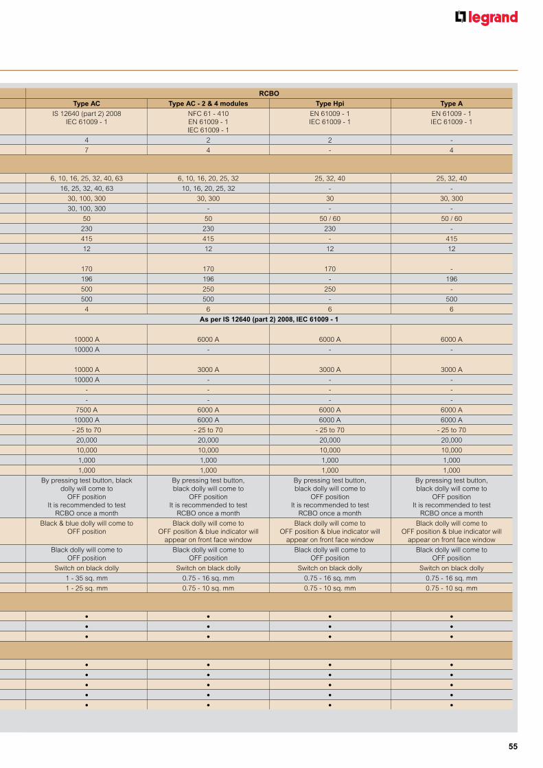
55
RCCB RCBOType AC Type A-S Type Hpi Type AC Type AC - 2 & 4 modules Type Hpi Type A
Specification IS 12640 (part 1) 2008 IEC 61008 - 1
IEC 61008 - 1 EN 61008 - 1
EN 61008 - 1 IEC 61008 - 1
IS 12640 (part 2) 2008 IEC 61009 - 1
NFC 61 - 410 EN 61009 - 1 IEC 61009 - 1
EN 61009 - 1 IEC 61009 - 1
EN 61009 - 1 IEC 61009 - 1
No. of modules - Double pole 2 2 2 4 2 2 -
- Four pole 4 4 4 7 4 - 4
Electrical characteristics
Nominal rating In (A) - Double pole 25, 40, 63, 80, 100 63, 80 25, 40, 63, 80 6, 10, 16, 25, 32, 40, 63 6, 10, 16, 20, 25, 32 25, 32, 40 25, 32, 40
- Four pole 25, 40, 63, 80, 100 25, 40, 63, 80 25, 40, 63, 80 16, 25, 32, 40, 63 10, 16, 20, 25, 32 - -
Rated sensitivity (mA) - Double pole 30, 100, 300 300 30 30, 100, 300 30, 300 30 30, 300
- Four pole 30, 100, 300 300 30 30, 100, 300 - - -
Rated frequency (Hz) 50 / 60 50 / 60 50 / 60 50 50 50 / 60 50 / 60
Rated operating voltage - Double pole 230 230 230 230 230 230 -
Ue (V AC) - Four pole 230 / 415 400 400 415 415 - 415
Minimum operating voltage (V AC) 12 12 12 12 12 12 12
Minimum operating voltage for test button (V AC)(1)
- Double pole 170 170 170 170 170 170 -
- Four pole 196 196 196 196 196 - 196
Rated insulation - Double pole 250 250 250 500 250 250 -
voltage Ui (V AC) - Four pole 500 500 500 500 500 - 500
Rated impulse withstand voltage Uimp (kV) 6 6 6 4 6 6 6
Breaking capacity As per IS 12640 (part 1) 2008, IEC 61008 - 1 As per IS 12640 (part 2) 2008, IEC 61009 - 1Rated making & breaking capacity (Im)
- Up to 40 A 500 A - 500 A 10000 A 6000 A 6000 A 6000 A
- From 63 A and above 10 x In 630 A 630 A 10000 A - - -
Rated residual making & breaking capacity (I∆m)
- Up to 40 A 1000 A - 1000 A 10000 A 3000 A 3000 A 3000 A
- From 63 A and above 1000 A 1000 A 1000 A 10000 A - - -
Rated conditional short circuit current (Inc) 10000 A 10000 A 10000 A - - - -
Rated conditional residual short circuit current (I∆c) 10000 A 10000 A 10000 A - - - -
Rated service short circuit capacity (Ics) - - - 7500 A 6000 A 6000 A 6000 A
Rated short circuit capacity (Icn) - - - 10000 A 6000 A 6000 A 6000 A
Operating temperature (0C) - 25 to 70 - 25 to 70 - 25 to 70 - 25 to 70 - 25 to 70 - 25 to 70 - 25 to 70
Endurance (0.C cycle) - Mechanical 20,000 20,000 20,000 20,000 20,000 20,000 20,000
- On load at in X cos j 0.9 10,000 10,000 10,000 10,000 10,000 10,000 10,000
- Via test button 2,000 2,000 2,000 1,000 1,000 1,000 1,000
- By fault current (sensitivity) 2,000 2,000 2,000 1,000 1,000 1,000 1,000
Testing By pressing test button grey dolly will come to
OFF position It is recommended to test
RCCB once a month
By pressing test button grey dolly will come to
OFF position It is recommended to test
RCCB once a month
By pressing test button, grey dolly will come to
OFF position It is recommended to test
RCCB once a month
By pressing test button, black dolly will come to
OFF position It is recommended to test
RCBO once a month
By pressing test button, black dolly will come to
OFF position It is recommended to test
RCBO once a month
By pressing test button, black dolly will come to
OFF position It is recommended to test
RCBO once a month
By pressing test button, black dolly will come to
OFF position It is recommended to test
RCBO once a month
Fault indication - Earth leakage Grey dolly will come to OFF position
Grey dolly will come to OFF position
Grey dolly will come to OFF position
Black & blue dolly will come to OFF position
Black dolly will come to OFF position & blue indicator will
appear on front face window
Black dolly will come to OFF position & blue indicator will
appear on front face window
Black dolly will come to OFF position & blue indicator will
appear on front face window
- Overload and shortcut - - - Black dolly will come to OFF position
Black dolly will come to OFF position
Black dolly will come to OFF position
Black dolly will come to OFF position
Resetting Switch on grey dolly Switch on grey dolly Switch on grey dolly Switch on black dolly Switch on black dolly Switch on black dolly Switch on black dolly
Terminals - Rigid 1 - 35 sq. mm 1 - 35 sq. mm 1 - 35 sq. mm 1 - 35 sq. mm 0.75 - 16 sq. mm 0.75 - 16 sq. mm 0.75 - 16 sq. mm
- Flexible 1 - 25 sq. mm 1 - 25 sq. mm 1 - 25 sq. mm 1 - 25 sq. mm 0.75 - 10 sq. mm 0.75 - 10 sq. mm 0.75 - 10 sq. mm
Type of protection
Earth leakage • • • • • • •Overload - - - • • • •Short circuit - - - • • • •
Add on electrical accessories*
Auxiliary • • • • • • •Fault signaling • • • • • • •Shunt trip • • • • • • •Under voltage • • • • • • •Over voltage • • • • • • •* - Accessories are mounted on the left hand side of the product. At a time a maximum of three accessories can be mounted.(1) - Between phase and neutral
DX3 RCDSTechnical data for DX3 RCDs

56
DX3
RCDs
DX3
RCD downstream DX3 MCB upstream
2P
16 1025 1040 10 63 1080 10100 10
4P
25 1040 1063 10 80 10100 10
Marking example :
Type A
Type AC
Type A-S
Type Hpi
n Technical data
Short-circuit withstanding capacity of RCCBs (in kA)
How can we protect ourselves?There are two ways (independent of the neutral earthing system) of ensuring that personnel are protected against direct contact.• Preventing access to live parts where possible.Basic protection via physical or electrical isolation of live parts.This protection must ensure that live parts cannot be touched, even inadvertently.
How?By using barriers, enclosures, closed cabinets which physically or electrically isolate live parts presenting a danger to the user, shuttered sockets, or insulation.
• Additional protectionMust be provided by a 30-mA residual current device such as Lexic range of residual current devices. This protection is required in case the basic protection detailed above fails.
Direct contactsDirect contact is caused by humans and may be due to either carelessness or clumsiness.What is a direct contact? How can we protect ourselves? Here are the answers...This is when someone makes contact with a live electrical component of a device or installation. For example :• a person inadvertently touching a live cable.• a child sticking a metal object into a power socket.• using male/male extensions or unprotected test cables.
Direct and indirect contact
All electrical risks for people are the result of direct or indirect contact. What are these contacts? And how can we protect ourselves against them?All the answers appear in the following section.Electrical risks do not just concern people : these risks - especially fire affect installations as well. A 500 mA current, for example, flowing through combustible material is sufficient to ignite such material after a certain time. Every electrical installation is subject to current leakages which can vary considerably depending on such factors as the installation's condition, age, environment, etc.These current leaks may flow through the fabric of the building (trunking, metal girders or other metal components), generating heat which in turn may lead to fire.
In this case only basic protection is effective
Other examplesSomeone touching a live busbar in a distribution panel or cabinet, or someone touching flush-mounted electrical trunking with the end of a tool, etc. In this case basic protection plus additional protection is effective.
n Technical data
Nature and consequences of electrical risks
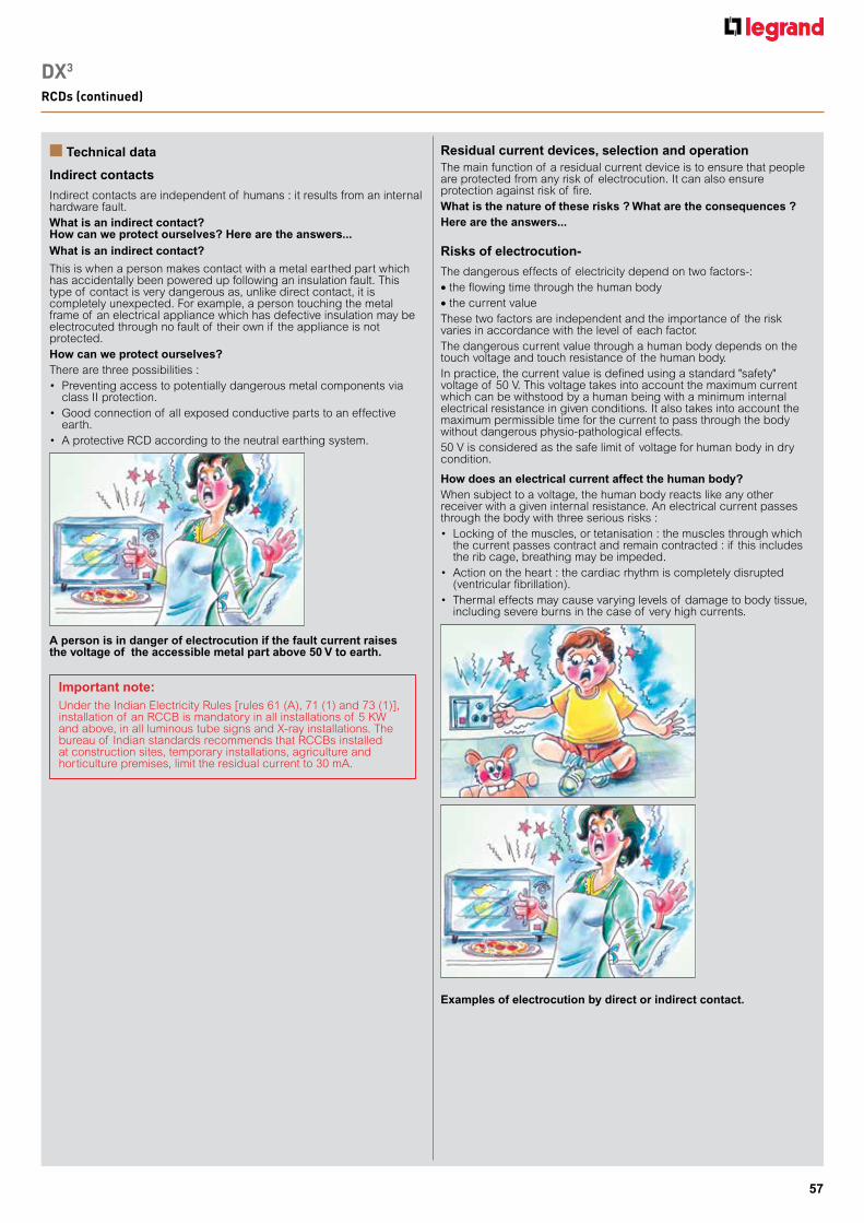
57
DX3
RCDs (continued)
n Technical data
Indirect contacts
Indirect contacts are independent of humans : it results from an internal hardware fault.What is an indirect contact? How can we protect ourselves? Here are the answers...What is an indirect contact?
This is when a person makes contact with a metal earthed part which has accidentally been powered up following an insulation fault. This type of contact is very dangerous as, unlike direct contact, it is completely unexpected. For example, a person touching the metal frame of an electrical appliance which has defective insulation may be electrocuted through no fault of their own if the appliance is not protected.How can we protect ourselves?There are three possibilities :• Preventingaccesstopotentiallydangerousmetalcomponentsvia
class II protection.• Goodconnectionof allexposedconductivepartstoaneffective
earth.• AprotectiveRCDaccordingtotheneutralearthingsystem.
A person is in danger of electrocution if the fault current raises the voltage of the accessible metal part above 50 V to earth.
Important note:Under the Indian Electricity Rules [rules 61 (A), 71 (1) and 73 (1)], installation of an RCCB is mandatory in all installations of 5 KW and above, in all luminous tube signs and X-ray installations. The bureau of Indian standards recommends that RCCBs installed at construction sites, temporary installations, agriculture and horticulture premises, limit the residual current to 30 mA.
The main function of a residual current device is to ensure that people are protected from any risk of electrocution. It can also ensure protection against risk of fire.What is the nature of these risks ? What are the consequences ? Here are the answers...
Risks of electrocution-
The dangerous effects of electricity depend on two factors-:• the flowing time through the human body• the current valueThese two factors are independent and the importance of the risk varies in accordance with the level of each factor.The dangerous current value through a human body depends on the touch voltage and touch resistance of the human body.In practice, the current value is defined using a standard "safety" voltage of 50 V. This voltage takes into account the maximum current which can be withstood by a human being with a minimum internal electrical resistance in given conditions. It also takes into account the maximum permissible time for the current to pass through the body without dangerous physio-pathological effects.50 V is considered as the safe limit of voltage for human body in dry condition.
How does an electrical current affect the human body?When subject to a voltage, the human body reacts like any other receiver with a given internal resistance. An electrical current passes through the body with three serious risks :• Lockingof themuscles,ortetanisation:themusclesthroughwhich
the current passes contract and remain contracted : if this includes the rib cage, breathing may be impeded.
• Actionontheheart:thecardiacrhythmiscompletelydisrupted(ventricular fibrillation).
• Thermaleffectsmaycausevaryinglevelsof damagetobodytissue,including severe burns in the case of very high currents.
Residual current devices, selection and operation
Examples of electrocution by direct or indirect contact.

58
i∆ : current flowing through body. t : time taken for current to pass through body.
These curves show the various zones of effect of an alternating current on people : they derive from IEC 60 479 and determine
4 main risk zones
Effect of current on human body
The standards define the following curves, which take into account the two parameters required to assess the risk :
Zonedesignation
Physiological effects
zone AC-1 Usually no reactionzone AC-2 Usually no harmful physiological effectszone AC-3 Usually no organic damage to be expected. Likelihood of cramp like
muscular contractions and difficulty in breathing for durations of current-flow longer than 2 s. Reversible disturbances of formation and conduction of impulses in the heart, including atrial fibrillation and transient cardiac arrest without ventricular fibrillation increasing with current magnitude and time
zone AC-4 Increasing with magnitude and time, dangerous pathophysiological effects such as cardiac arrest, breathing arrest and serious burns may occur inaddition to the effects of zone-3
zone AC-4.1 Probability of ventricular fibrillation increasing up to about 5% C1 - C2zone AC-4.2 Probability of ventricular fibrillation up to about 50% C2 - C3zone AC-4.3 Probability of ventricular fibrillation above 50%
* For durations of current flow below 10 ms, the limit for the body current at line b remains constant at a value of 200 mA.
A residual current device continuously measures the difference between the value of the input and the output currents. If the value is not equal to zero, this indicates a leak. When this leak reaches the level at which the differential is set (its sensitivity), the device trips and breaks the circuit.What are the operating principles of a residual current device?What are the selection criteria for a residual current device? Here are the answers...
Operating principle of a residual current device
Selecting a residual current device
First determine your requirement. This exists on two levels :1 The need to protect against direct or indirect contacts.2 The need to ensure protection against overloads and short-circuits.If protection against indirect contact is required, use residual current devices with a sensitivity of : 30 mA, 100 mA, 300 mA,The rating (40, 63 A, etc.) is selected according to the load.If protection against direct contact is required, use residual current device with a sensitivity of 30 mA.The sensitivity of a residual current device I∆n is the current level at which tripping is sure to occur. To do this, the standards concerning residual current devices stipulate that tripping must occur between I∆n / 2 and I∆n.
No fault present
Therefore no current is induced in coil K1, and coil K2 is not excited. The contacts do not open. The equipment operates normally
If = 0, thusI1 = I2
∅1 = ∅2
∅1 - ∅2 = 0
Insulation fault
A current is thus induced in coil K1...If ≠ 0I1 > I2, thus∅1 > ∅2, thus∅1 - ∅2 ≠ 0
...coil K2 is excited, the contacts open and the equipment is automatically switched OFF
DX3
RCDs (continued)
n Technical data

59
Types of residual current device
There are 2 types of RCD : the AC type and the A typeBoth types are produced in the "S" (discriminating) or normal versions. They conform to Indian and International standards IS 12640, IEC 61008 and IEC 61009 as well as European standards EN 61008 and EN 61009.
• Type A
Sensitive to residual alternating currents and residual currents with a DC component.Use : special applications- if it is possible that the fault currents are not purely sinusoidal (rectifier bridge, etc.)
• Type AC
Sensitive to residual alternating currents Use : standard applications
• Type S
Delayed trip for discrimination with other residual current devices. Use : for discrimination with a downstream device.
• Type Hpi
• Enhanced immunity to unwanted tripping in environments with disturbances. eg. diesels, computers, printers, etc.• Detects faults with DC components eg. thyristors, trio etc.
Residual current circuit-breaker with or without overload protection? Which do I choose?
Choose a residual current circuit-breaker (RCCB) if you do not need to protect against overload and short circuits (caution! an RCCB must be connected to some form of line protection device : either a circuit-breaker or a fuse).Choose a residual current circuit-breaker with overload and short circuit protection (RCBO) if this type of protection is not available.
Residual current circuit-breakers without overload and short circuit protection (RCCB)
The "test" functionA residual current device is a safety device, and it is therefore vital that it is regularly tested. This function is therefore required by the standard governing residual current protective devices, and ensures correct operation. All Lexic RCDs are equipped with this function.
These provide three functions : fault current detection, measurement and cut-off : protection against overloads and short-circuits : and isolation of an installation.
Residual current circuit-breakers are governed by standards IS 12640 (part 2), IEC 61009-1.
Residual current circuit-breakers with overload and short circuit protection (RCBO)
These provide two functions : fault current detection, measurement and cut-off : and isolation of an installation.RCCBs are governed by standards IS 12640 (part 1), IEC 61008-1.
Note : We offer Type AC, Type A-S and Type Hpi RCDs
DX3
RCDs (continued)
n Compatibility MCBs/add-on modules
Breaking capacity
Number of poles
Add-on module for 1.5 module/pole MCBs
16 kA 2P, 4P In ≥ 80 A
25 kA
4P In ≥ 32 A
2P In ≥ 40 A
4P In ≥ 12,5 A
2P In ≥ 32 A
50 kA 2P, 4P All range
Add-on modules DX3
n Technical data

60
STOP&GO automatic resetting for DX3
Temporarily electrical disturbances and other external events can cause unwanted tripping of different devices protecting electrical installation
STOP&GO verifies automatically the state of the installation, before resetting and launches a visual and close a contact in case of permanent fault detection (short-circuit or residual current)
After verifying the state of the installation, STOP&GO automatic resets the associated protection device in order to immediatly re-establish power supply and avoid unwanted consequences
STOP&GO does not protect the installation against lightning strikes For an efficient protection against lightning, use voltage surge protectors
The Autotest version is specially suitable for installations equipped with residual current protection devices (RCD's and RCBOs) STOP&GO periodically does an automatic test of the functionning of residual current protection devices. The manual test is no longer needed
Alarm Heating Swimming pool Refrigerator
Access control Freezer Aquarium Watering
Mains fault due to temporarily electrical disturbances Electrical devices are not powered anymore
STOP&GO automatic resets the associated protection device in order to immediatly re-establish power supply
Installation without STOP&GO Installation with STOP&GO
n Operating principle n Technical characteristics of auxiliariesMax. connection cross-section: 2.5 mm2
Operating temperature: - 25 °C to + 70 °C
Nominal voltage (Un)- 12 to 48 V± and =- 110 to 415 V± and 110 to 125 V=
N
Ph
58
C1
56 R
V
55
250VA6A
Undervoltage releases
Pull-in voltage ≥ 0.55 UnTripping time: 0 to 300 ms ± 10% (adjustable)Power consumption: 24 VA and = : 0.1 VA
48 VA and = : 0.2 VA 230 V± : 1 VA
Nominal voltage:24 and 48 VA and =230 V±
N/-
Ph/+
U
A2A1
Stand-alone releases for N/C push-buttons
Min. and max. operating voltage: 196 to 250 V± Power consumption: 1.4 VA
L230VAN
U
E1
A2
A1 1
2
n...
Signalling auxiliaries
Umin.: 24 V± / = and Imin.: 5 mA
Consumption Umin. Umax.12 to 48 V 522 mA 2610 mA
110 to 415 V 69 mA 259 mA
Shunt trips
Equipped with a signalling contact which indicates tripping of the shunt trip and automatically breaks the coil. Min. and max. voltage: 0.7 to 1.1 UnTripping time: less than 20 msPower consumption: at 1.1 x 48 V = 121 VA at 1.1 x 415 V = 127 VAImpedance: 12 to 48 V = 23 Ω 110 to 415 V = 1640 Ω
Performance of MCBs and auxiliaries

61
Performance of MCBs and auxiliaries Protection of DC circuits
Example: for a 110 V voltage, use a 2-pole MCB and connect the 2 poles in series
4 - Breaking capacity
For other voltages, the breaking capacities are as follows:
4000 A for a single pole MCB at max. voltage (80 V= per pole)
+
-
+
-
+
-
+
-
1: Only if isolation required
MCB (U-Isc max.)
U U-Isc max
U=0 (1)
+
-
5 - Distribution of breaking poles
Place all the poles necessary for breaking on the other polarity If isolation is required, an additional pole must be added on the earthed polarity
•Supply with one polarity earthed:
To choose the MCB and determine the pole distribution necessary for breaking on each of the polarities, it is necessary to know how the installation is earthed
DX3 6000 voltage single-pole 2P 3P 4P
Acc. to
IEC 60947.2
Icu
≤ 48 V 6 kA 6 kA
110 V 6 kA 6 kA
230 V 10 kA
Ics(1)
≤ 48 V 100 % 100 %
110 V 100 % 100 %
230 V 100 %
DX3 10000 voltage single-pole 2P 3P 4P
Acc. to
IEC 60947.2
Icu
≤ 48 V 10 kA 10 kA
110 V 10 kA 10 kA
230 V 15 kA
Ics(1)
≤ 48 V 100 % 100 %
110 V 100 % 100 %
230 V 100 %
1: As a % of Icu
n Protection of DC circuitsDX3 6000 and DX3 10000 MCBs (1P/2P/3P/4P - In ≤ 63 A) designed for use in 230/400 V± supplies, can also be used in DC circuitsIn this case, the following deratings and precautions must be taken into account
Max. magnetic tripping threshold: multiplied by 1.4Example: For a C curve MCB for which the AC tripping threshold is between 5 and 10 In, the DC tripping threshold will be between 7 and 14 In
Max. operating voltage: 80 V per pole (60 V for single-pole + N MCBs)For voltages higher than this value, several poles must be wired in series
The time/current thermal tripping curve is the same as for AC
1 - Protection against short-circuits
2 - Protection against overloads
3 - Operating voltage
n Electric wiring diagram
Cat.No 4062 86
255 V 275 V 300 V 350 V 400 V
Breaking time No tripping
15 Sec 5 Sec 0.75 Sec 0.20 Sec
Non actuation time 3 Sec 1 Sec 0.25 Sec 0.07 Sec
Tripping time:Limit values of breaking time and non actuation time at a voltage
CA / SD / ET / MT / DA CM
3 2 1
4062 91/ 93/95
4062 58/ 60/62/66
4062 91/ 93/95
4062 58/ 60/62/76/78/ 80/82/84/87
4062 58/ 60/62
4062 914062 58/
60/62/66/76/ 78/80/82/84/87
4062 66
4062 58/ 60/62
4062 58/ 60/62
4062 93/954062 58/ 60/62/66 4062 66
Combinations with auxiliaries:
U>
A1
A1 A2A2
N
L

62
Protection of DC circuits Programmable time switcheswith analogue and digital dial
n Diagrams
Cat.Nos 4127 90/94 Cat.Nos 4128 12/13/14
Output
U1 U2 1 4 2
N L
16 A
N L
Cat.No 4126 31N L
3
L
N
L
N
21
4
21
4
Cat.Nos 4126 54/34/29 Cat.Nos 4126 57/41/30
Output closing and breaking times are calculated based on the date, the actual time when the device was switched and on geographical coordinates of the actual location
DX3 10000 voltage single-pole 2P 3P 4P
Acc. to
IEC 60947.2
Icu
≤ 48 V 10 kA 10 kA
110 V 10 kA 10 kA
230 V 15 kA
DX3 6000 voltage single-pole 2P 3P 4P
Acc. to
IEC 60947.2
Icu
≤ 48 V 6 kA 6 kA
110 V 6 kA 6 kA
230 V 10 kA
DX3 6000 voltage single-pole 2P 3P 4P
Acc. to
IEC 60947.2
Icu
≤ 48 V 6 kA 6 kA
110 V 6 kA 6 kA
230 V 10 kA
Example: circuit earthed via the negative polarity / U = 110 V= / Isc = 10 kA / In = 32 AProtect the positive polarity using an MCB capable of breaking 10 kA at 110 V (DX3 10000 2P 32 A with 2 poles on the positive polarity)For isolation, use a DX3 10000 3P 32 A with 2 poles on the positive polarity and one pole on the negative polarity
1: MCB (U/2-Isc max.)
(1)
(1)
U/2
U/2
U-Isc max.
U/2-Isc max.
U/2-Isc max.
+
-
U-Isc max.
U-Isc max. 1st earth fault: I = O2sd earth fault:U and I Isc max.
U
+
-
1: MCB (U-Isc max.)
(1)
(1)
•Network earthed via a middle point:Place on each polarity the number of poles necessary for max. Isc breaking at half voltage
Example: circuit earthed via a middle point / U = 230 V= / Isxc = 6 kA / In = 10 A Protect each polarity using an MCB capable of breaking 6 kA at half voltage, i.e. 115 V
•Isolated earth supply:Distribute the poles necessary for breaking over the 2 polarities to provide protection in the event of a double earth fault (particularly if there are a number of circuits in parallel)
Example: isolated earth circuit / U = 48 V= / Isc = 4,5 kA / In = 40 AProtect the installation with an MCB capable of breaking 4.5 kA at 48 V and protect each polarity
+
-
DX 10 A 4P
DX3 600010 A 4P
DX 40 A 2P
+
-
DX3 600040 A 2P
DX-H 32 A 2P
DX-H 32 A 3P
If isolation required + +
-
-
DX3 1000032 A 2P
DX3 1000032 A 3P
n Protection of DC circuits

63
n Technical specifications
TypeAlphaRex3
D21AlphaRex3
D22AlphaRex3
D21sAlphaRex3 D21 astro
AlphaRex3 D22 astro
AlphaRex3 DY21
AlphaRex3 DY22
Nominal voltage 230 V 50/60 Hz 4126 31 4126 41 4126 34 4126 54 4126 57 4126 29 4126 30Number of modules of 17.5 mm each 2 2 2 2 2 2 2Number of channels 1 2 1 1 2 1 2
Switch output 1 changeover contact
2 changeover contacts
1 changeover contact
1 changeover contact
2 changeover contacts
1 changeover contact
2 changeover contacts
Zero-crossing switching ü ü ü ü ü ü üSwitching capacity•Ohmic 250 V± cos j = 1 16 A± 16 A± 16 A± 16 A± 16 A± 16 A± 16 A±•Inductive 230 V± cos j = 0.6 10 A± 10 A± 10 A± 10 A± 10 A± 10 A± 10 A±•Incandescent lamp load 2000 W 2000 W 2000 W 2000 W 2000 W 2000 W 2000 W•Fluorescent lamp, series compensated 2000 VA 2000 VA 2000 VA 2000 VA 2000 VA 2000 VA 2000 VA•Energy-saving lamp 1000 W 1000 W 1000 W 1000 W 1000 W 1000 W 1000 W
Programs1) 56 28 per channel 56 56 28 per channel 84 84 per channelControl input with switch-off delay0 s to 23 h 59 min 59 s
ü ü ü
Cycle function (pulse time)min. 1 s, max. 1 h 59 min 59 s
ü ü ü ü ü ü ü
Clock precision (typical) ± 0.1 s/day 2)
Running reserve 5 yearsShortest switching step 1 sOperating temperature –20 to +55 °CDegree of protection IP20
n Connection diagram
n Functions
n Data key
n Brief description of programming functions
1) A program consists of a switch-on time, a switch-off time as well as days or day blocks which are assigned as “switched-on” or “switched-off” 2) Can be set to mains-synchronous operation
If the supply voltage is switched on, the “KEY – READ – WRITE” menu item is automatically opened when a data key is inserted. “WRITE”: Program data is written from the time switch to the key. Caution: Any data present on the key will be overwritten. “READ”: Program data is written from the key to the time switch; any switching programs on the time switch are overwritten. Only one master switching program, which consists of multiple switching programs, can be saved on the time switch or on the key at a time. If the supply voltage is not connected, the “KEY – READ – WRITE” menu item is not automatically opened when a data key is inserted. The “KEY” function can still be selected from the menu even if the supply voltage is not connected.
n PC programming
In addition to the easy, text-guided programming directly on the time switch, switching programs can also be created on a PC with the software program from Legrand and transferred to the time switch using a data key. A data transfer device (Cat.No : 4128 73) is required to transfer switching programs created on a PC to the data key. The device is connected to the PC using the USB plug. In addition to the data transfer device, we also offer a CD with the software and the necessary drivers. PC system requirements: USB port; Windows® XP, Windows® Vista, Windows® 7; approx. 40 MB of free memory.
Text guidanceGuides the user through programming and setup with plain text prompts. Each step can be read on the screen, and the function that is currently active flashes. An integrated display and button light makes operation easy even in poorly lit environments.
Set languageThe language selection function can be accessed using the “MENU” button. The language is set to English by default.The following languages can be selected: German, English, French, Italian, Spanish, Dutch, Portuguese*, Swedish*, Norwegian*, Finnish*, Danish*, Polish*, Czech*, Russian*, Turkish*. *) Excluding AstroRex DY64
Time, date, summer time (daylight saving time)The time switch is preset at the factory to the current time and date. The time can be changed by selecting “MENU” + “SET”.
0 6 12 16 24
2 41
AlphaRex3 D21
0 6 12 16 24
AlphaRex3 D22AlphaRex3 D22 astroAlphaRex3 DY22
0 6 12 16 24
2 41
AlphaRex3 D21sAlphaRex3 D21 astroAlphaRex3 DY21
Select menu, go back while in menu Press > 1 sec. = operating display
Confirm the selection or accept the parameter
Select the menu item or set the parameter; for 2-channel time switches, can be used to select the channel (channel 1 – channel 2)
OK
-
+
ResetSimultaneously pressing all buttons for more than 2 seconds deletes all data. Language, date/time, summer time (daylight saving time) and switch times must be set again.
AlphaRex3 digital time switches

64
n Brief description of programming functions
n Basic functions for “astro”
Weekly programsTo create a weekly program, select “MENU”, “PROGRAM”, and then “CREATE” to easily enter programs which are repeated on a weekly basis. A weekly program consists of a switch-on/switch-off times and days which are assigned as “switched-on” or “switched-off”. The following predefined blocks can be selected: “MONDAY – SUNDAY”, “MONDAY – FRIDAY” 1) or “SATURDAY – SUNDAY”,1); the assigned days of the week are fixed. The switch-on/switch-off times must be entered. The user can also set custom day blocks. By selecting “CUSTOM”, switch times can be freely assigned to any days of the week. This option also allows the user to set switch times at midnight. 1) Excluding AlphaRex³ DY, AstroRex DY64 Yearly programs [AlphaRex3 DY21, AlphaRex3 DY22]This menu item allows the user to enter (additional) yearly programs, which are only executed within a defined validity period. They can overlap with one another and with the weekly programs on the same channel based on an “OR” connective. The validity period is defined by entering the start date (at 00:00:00) and the end date (at 24:00:00). The start date must be entered before the end date. With the “EVERY YEAR” option, the additional switch times have the same validity period each year (Christmas, national holidays, birthdays, etc.) Select the “ONCE” option when additional switch times are needed within a validity period (e.g. during holidays), but the start/end dates of the holiday period change from year to year. Special programs (priority program) [AlphaRex3 DY21, AlphaRex3 DY22]Weekly and yearly programs on the same channel are not executed during the validity period of a special program. However, other special programs can be executed during the validity period. Different special programs can overlap with each other based on an “OR” connective. With the “EVERY YEAR” option, the additional switch times have the same validity period each year (Christmas, national holidays, birthdays, etc.). Select the “ONCE” option when additional switch times are needed within a validity period (e.g. during holidays), but the start/end dates of the holiday period change from year to year. Additional options include “MON TO SUN”/“CUSTOM”: the respective channel only switches according to the special program; “PROG ON”/“PROG OFF”: the respective channel is switched on/off during this time period.
Location (astro) [AlphaRex3 D21 astro, AlphaRex3 D22 astro, AlphaRex3 DY21, AlphaRex3 DY22]The sunrise/sunset times, which change daily, are calculated for the location programmed in the AlphaRex. The unit is delivered with the location set to “GERMANY – SOEST” by default. Enter the actual location for optimal operation. This can be done in two ways. Select “MENU”, “SET” and “ASTRO” to access the two options “LOCATION” and “COORDINATES”. “LOCATION”: With this menu item, the user can select the country and city which is closest to the site of operation. “COORDINATES”: Alternatively, the user can select this menu item to set the geographical coordinates of the location. The longitude and latitude values are entered in degrees or degrees and arcminutes 2) (precision can be set in expert mode). Information on coordinates and time zones can be found in the time zone map included with every time switch. OffsetBy selecting “MENU”, “SET”, “ASTRO” and “OFFSET”, time differentials can be set for the calculated switch times. This can be done in two ways: time offset or angle offset. In time offset, a time differential can be entered to shift the switch time by up to +/- 120 min relative to the sunrise/sunset times. In angle offset 2), a value can be entered in degrees and arcminutes to shift the switch time by up to +/- 12° 00´ relative to the sunrise/sunset times. The time differentials are set separately for sunrise and sunset using the menu items “SUNSET” (opens the screen for setting the sunset offset) and “SUNRISE” (opens the screen for setting the sunrise offset).
Offset correction function 2)
Select “MENU”, “SET”, “ASTRO” and “CORRECTION” to set a time correction for the 6-month periods surrounding summer and winter. The time correction is set to 0 min. by default and can be set from 1 min. up to 30 min. The time correction for sunset is entered in the “SUNSET” menu item. The time correction for sunrise is set in the “SUNRISE” menu item. The correction function overlaps with the calculated astronomical switch times, including the offset settings. Example: Setting a time correction extends the daily switched-on time by up to 60 min. in the middle of the six winter months (switches off up to 30 min. later in the morning and switches on up to 30 min. earlier in the evening). In the middle of the six summer months, the time correction reduces the daily switched-on time by up to 60 min. (switches off up to 30 min. earlier in the morning and switches on up to 30 min. later in the evening). The time correction varies continuously between the two max. values during the rest of the year.Basic settings using a PC and day keyAll of the basic settings described above, with the exception of the current time and date, can be set up using the AlphaSoft software from Legrand and imported to the time switch using the data key. 2) Excluding AstroRex DY64
0h 3 6 9 12 15 18 21 24h t
1
0 + +max. ± 120minmax. ± 120min
0h 3 6 9 12 15 18 21 24h
1
0 + +
+12˚
+6˚
-50’
-6˚
-12˚
Example: For a time differential of +30 min, the time switch switches 30 min. after sunrise and 30 min. after sunset. For a time differential of -30 min, the time switch switches 30 min. before sunrise and 30 min. before sunset.
Note: If the offset is set in degrees, the time switch always switches at points when the brightness is the same, despite the fact that the twilight duration changes over the course of the year. Sunrise and sunset correspond to -50' for the centre of the sun (the edge of the sun is visible on the horizon).
Tim
e of
fset
Ang
le o
ffse
t
AlphaRex3 digital time switches

65
Relay functionThe relay state can be changed by selecting “MENU” and “FUNCTIONS”. The relay is preset to the “AUTO” function; the time switch switches at the programmed times. The following can also be selected: “ALWAYS ON”, “ALWAYS OFF” and “EXTRA”. If “EXTRA” is selected, the switching status specified by the program is inverted. The time switch resumes switching according to the programmed switch times after the next switch command.
Holiday programIn holiday program, the holiday period is set with a start and an end date. It can be activated with the “ACTIVE” program item and deacti-vated with “PASSIVE”. If the holiday program is activated, the time switch does not carry out any programmed switch commands during this time period. Instead, it remains “ALWAYS OFF” or “ALWAYS ON” during the holiday period, as requested. When the holiday period has ended, the time switch resumes switching according to the programmed switch times.
1 h testThe “1 h TEST” function can be used for a switching simulation. If “1 h TEST” is activated, the switch outputs are switched for one hour. After the time has ended, the time switch resumes switching according to the programmed switch times.
PIN codeInput and programming can be locked using a four-digit “PIN CODE”. The time switch can be unlocked using the “PIN CODE”. The time switch can also be unlocked using the “RESET” function, which also deletes all settings and programs.
Operating hours counterThis function displays the time for which the relay has been switched on and the date of the last reset. Counting range: 65,535 h.
Contrast adjustmentThis function allows the user to adjust the display contrast.
Expert mode* Expert mode is activated by selecting “OPTIONS” and “EXPERT”. After expert mode is activated, the following additional functions can be used: control input “extra” 1), control input “out” 1), cycle function, channel-switching function (2-channel time switches), mains-synchronous operation, offset correction function 2), geographical coordinates in degrees and arcminutes 2). 1) AlphaRex3 D21s, AlphaRex3 D21 astro, AlphaRex3 DY21 2) AlphaRex3 astro, AlphaRex3 DY
Control input with switch-off delayAdjustable switch-off delay via control input. The control input enables an additional switching of the relay, parallel to the switching program. The switch-off delay can be set from 0 s to 23 h 59 min 59 s. The switch-off delay begins as soon as the voltage is removed from the control input.
Control input “extra”*Override of switching state via control input. If the “EXTRA” function is activated, the switching state specified by the program is inverted. The time switch resumes switching according to the programmed switch times after the next switch command. The “EXTRA” function is ended prematurely if the button is pressed again or if a pulse is received at the control input.
Control input “off”* Switch off via control input. Activating the “OFF” function causes the time switch to be switched off via the control input. The “OFF” function is ended if the button is pressed again or if a pulse is received at the control input. The time switch resumes switching on/off according to the programmed switch times.
Pulse function Programmable with precision to the second.
Cycle functionFunction for cyclical switching. With this function, the time switch is switched on once within a defined time period and for a defined duration. The cycle time can be set between 2 s and 2 h. The switch-on time can be set between 1 s and 1 h 59 min 59 s.
Random functionIf the random function is activated, set switch times are randomly shifted within a range of +/- 15 minutes.
Channel-switching function*With 2-channel time switches, this function can be activated so that the time switch regularly switches between the outputs assigned to the channels, in order to protect connected devices (for example lights/lamps) or so that two devices can be used simultaneously. The channel-switching function is activated by selecting “MENU”, “OPTIONS” and “CHANNEL 1<>2”. The time switch switches between the outputs according to whether the menu item “DAILY” (once per day at 12:00 p.m.) or “WEEKLY” (once per week on Sunday at 12:00 p.m.) is selected.
Mains-synchronous operationMains-synchronised clock precision. By activating the “SYNC” function and then “ACTIVE”, the quartz-controlled time switch becomes a synchronous time switch. *) Excluding AstroRex DY64
Min. Max.
Cycle 2 s 2 hSwitch-on time 1 s 1 h 59 min 59 s 1 s ... 1 h 59 min 59 s
Zyklus max 2 h
n Additional functions
AlphaRex3 digital time switches

66
n Technical specifications
n Connection diagram
Type MicroRex T31
MicroRex QT31
MicroRex W31
MicroRex QT11
MicroRex QW11
Number of modules of 17.5 mm each
3 1
Number of channels 1 1 1 1 1Drive type synchronous quartz synchronous quartz quartzSwitching dial 24 h 24 h 7 days 24 h 7 daysRunning reserve none 100 h none 100 h 100 hSwitching increment 15 min 15 min 2 h 15 min 2 hShortest switching step 30 min 30 min 4 h 15 min 2 hSwitching step +/- 5 min +/- 5 min +/- 30 min +/- 5 min +/- 30 minClock precision mains 2.5 s/day mains 2.5 s/day 2.5 s/day
synchronised synchronisedSwitching capacity• Ohmic 230 V± cos j = 1 16 A±• Incandescent lamp 230 V± 4 A±• Inductive 230 V± cos j = 0.6 12 A±Switch output 1 changeover
contact1 changeover
contact1 changeover
contact1 normally
open contact1 normally
open contactOperating temperature -10 to +55 °CDegree of protection IP20
50 m maxi
Livrée avecl'appareil
cellulephoto-électrique
N L Photoelectric cell(supplied)
n Standard light sensitive switch (Cat.No 4126 23)
Switch "ON" and "OFF" defined by a light level threshold
Rex Analogue Time Switches and CX³ switches & indicators
MicroRex – 3 modules MicroRex – 1 module Wall bracket – 3 modules
3-module MicroRex units can be surface mounted using the wall bracket. A terminal cover is included with delivery.
Cat.No 4128 59
40
n CX³ Changeover switches
CX³ Push-buttons and control switches
CX³ LED indicaotrs
Power dissipation per role : 1.5 wOvervoltage category : 4 kV±Dielectric withstand : 2 kV±Degree of pollution : 2
Electrical endurance : 30 000 cycles AC12(cos j = 0.9) IEC 60947-5-1Electrical endurance under fluorescent loads : 30 000 cyclesaccording to IEC 60669-1
Equipped with non replaceable LED lampsLED life : 100 000 h.LED consumption : - 0.17 W under 230 V± - 0.11 W under 24 V±

67
n Technical characteristics
- Iq = 6 kA for 16 to 25 A contactors- Iq = 3 kA for 40 to 63 A contactorsCircuit breaker or gG fuse rated:
•≤16Afor16Arating •≤ 40 A for 40 A rating•≤25Afor25Arating •≤ 63 A for 63 A rating
Contactor protection against short circuits according to standard EN 61095, conditional short-circuit current:
•Ratedimpulsewithstandvoltage(Uimp):4kV•Mechanicalendurance(no.ofoperatingcycles):106 cycles•Operatingtemperatures:-25°Cto+40°C•Storagetemperatures:-40°Cto+70°C
40 A and 63 A power contactors
Coil voltage 24 VA 230 VA
Current 40 A and 63 A
40 A and 63 A
40 A and 63 A
40 A and 63 A
Type of contact 2 NO 4 NO 2 NO2 NC
3 NO4 NO4 NC
Dimensions 2 mod. 3 mod. 2 mod. 3 mod.
Holding current 250 mA 270 mA 15 mA 30 mA
Inrush current 1750 mA 1500 mA 150 mA 200 mA
16 A and 25 A power contactors
Coil voltage 24 VA 230 VA low noise 230 VA
Current 16 A and 25 A 25 A 25 A 16 A and
25 A16 A and
25 A
Type of contact NC + NO2 NO 4 NO 2 NO
NC + NO2 NO2 NC
2 NC + 2 NO4 NO4 NC
Dimensions 1 mod. 2 mod. 1 mod. 1 mod. 2 mod.
Holding current 200 mA 300 mA 12 mA 20 mA 20 mA
Inrush current 970 mA 2500 mA 60 mA 90 mA 200 mA
• Consumption of a contactor control coil
• Recommendations
Insert a spacing module (Cat.No 4063 07 p. 40): - every two contactors when the ambient temperature is below 40 °C - every contactor when the ambient temperature is between 40 and 60 °C
Contactor rating 40 °C 50 °C 60 °CIe = 16 A 16 A 14 A 12 A
Ie = 25 A 25 A 22 A 20 A
Ie = 40 A 40 A 36 A 32 A
Ie = 63 A 63 A 57 A 50 A
• Max. connection cross-section in mm2
Conductor type Ratings ≤ 25 A Ratings 40 & 63 ARigid 62 or 2 x 2.52 252 or 2 x 10²
Flexible 62 or 2 x 2.52 252 or 2 x 10²
Flexible with single end cap 62 162
Flexible with double end cap 2 x 42 2 x 162
• Fluorescent tubes with electronic ballast
Single fluorescent Double fluorescent
Nominal wattage 18 W 30 W 36 W 58 W 2 x 18 W 2 x 36 W 2 x 58 W
16 A 72 42 36 22 36 20 12
25 A 110 68 58 36 56 30 19
40 A 165 102 87 54 84 45 29
63 A 248 153 131 81 126 68 43
Triple fluorescent (series compensated)
Quadruple fluorescent (series compensated)
Nominal wattage 3 x 14 W 3 x 18 W 4 x 14 W 4 x 18 W
16 A 34 26 26 20
25 A 46 38 37 28
40 A 62 51 52 39
63 A 84 69 73 55
Compact fluorescent with built-in electronic power supply
Nominal wattage 7 W 11 W 15 W 20 W 23 W
16 A 120 80 64 50 43
25 A 200 125 90 70 60
40 A 280 175 126 98 84
63 A 392 245 176 137 118
n Contactor selection charts (continued)
• Fluorescent tubes with ferromagnetic ballast
Single parallel compensated fluorescent
Double series compensated fluorescent
Nominal wattage 18 W 20 W 36 W 58 W 115 W 2 x
20 W2 x
36 W2 x
40 W2 x
58 W2 x
140 W
16 A 24 24 16 11 5 30 24 22 15 6
25 A 33 30 25 17 9 45 38 35 24 10
40 A 43 39 33 22 12 68 57 53 36 15
63 A 56 51 42 29 15 101 86 79 54 23
Quadruple series compensated fluorescent
Compact fluorescent with built-in starter
Nominal wattage 4 x 18 W 7 W 10 W 18 W 26 W
16 A 16 50 40 28 19
25 A 24 60 50 42 28
40 A 36 78 65 55 36
63 A 54 101 85 71 47
n Contactor selection charts
• Incandescent lamps
Tungsten and halogen filaments 230 VANominal wattage 40 W 60 W 75 W 100 W 150 W 200 W 500 W 1000 W
16 A 45 30 24 19 13 10 4 2
25 A 60 48 38 30 20 15 6 3
40 A 96 77 61 48 32 24 10 5
63 A 154 123 97 77 51 38 15 8
ELV halogen bulbs with ferromagnetic ballast
ELV halogen bulbs with electronic ballast
Nominal wattage 20 W 35 W 50 W 75 W 100 W 150 W 20 W 35 W 50 W 75 W 100 W 150 W
16 A 32 20 15 12 9 6 60 40 28 18 14 9
25 A 52 30 24 16 12 8 80 50 40 26 20 13
40 A 68 39 31 21 16 10 112 70 56 36 28 18
63 A 88 51 41 27 20 14 157 98 78 51 39 25
• Discharge lamps with compensation
High pressure sodium vapour
High pressure mercury vapour
Nominal wattage 70 W 150 W 250 W 400 W 1000 W 50 W 80 W 125 W 250 W 400 W
16 A 8 7 5 3 1 11 8 6 3 2
25 A 10 9 6 4 2 15 10 8 4 3
40 A 15 14 9 6 3 21 14 11 6 4
63 A 23 20 14 9 5 29 20 16 8 6
High pressure mixed
Nominal wattage 100 W 160 W 250 W 400 W
16 A 9 6 4 2
25 A 11 7 5 3
40 A 14 9 7 4
63 A 19 12 8 5
Metal halogenide Low pressure sodium vapour
Nominal wattage 35 W 70 W 100 W 150 W 250 W 400 W 18 W 35 W 55 W 90 W 135 W 180 W
16 A 10 6 5 3 2 1 12 6 5 3 2 2
25 A 15 9 7 5 3 2 20 10 7 5 3 3
40 A 23 14 11 8 5 3 30 15 11 8 5 5
63 A 34 20 16 11 7 5 45 23 16 11 7 7
Power contactors CX3

68
Cat.Nos 0046 70 0046 77 0046 80 0046 84
Number of modules 1 2 4 4
Connection Direct
Via a current transformer
Single-phase
Three-phase
Max. current 32 A 63 A 63 A 5 A (CT)
Metering and measurement
Total active energy
Total reactive energy
Partial active energy (reset)
Partial reactive energy (reset)
Active power
Reactive power
Apparent power
Current
Voltage
Frequency
Power factor
Time-of-use
Average active power
Max. average active power value
Dual tariff
Communication Pulse output
RS 485 interface
MID compliant
Operating conditions
Reference temperature 23 °C ± 2 °C
Operating temperature -20 to +55 °C -10 to +45 °C -5 to +55 °C
Storage temperature -40 to +70 °C -25 to +70 °C -25 to +70 °C
Consumption ≤ 8 VA ≤ 4 VA per phase ≤ 1 VA per phase
Heat dissipation ≤ 6.5 W ≤ 6 W ≤ 4 W
n Interfacing with IP communication network
1: For direct connection meters If connected via transformers, the resolution and maximum indication depend on the transformation ratios of these transformers
n Technical characteristicsSingle-phase meters Cat.Nos 0046 70/77LCD display: 7 digitsResolution: 0.1 kWhMaximum indication: 99999.9 kWhMetrological LED: 1 Wh/pulse (Cat.No 0046 70 : 0.5 Wh/pulse)Accuracy (EN 62053-21): class 1Reference voltage Un: 230 V-240 VReference frequency: 50-60 HzPulse output: 1 pulse/10 Wh (Cat.No 0046 70: 2 pulse/Wh)
Three-phase meters Cat.Nos 0046 80/84LCD display: 8 digitsResolution: 0.01 kWh(1)
Maximum indication: 99999.99 kWh(1)
Metrological LED: 0.1 Wh/pulse or 1 Wh/pulseActive energy accuracy (EN 62053-21): class 1Reactive energy accuracy (EN 62053-23): class 2Reference voltage Un: - Single-phase: 230-240 V - Three-phase: 230(400)-240(415) VOperating limit range (EN 62053-21, EN 62053-23): - Single-phase: 110 to 254 V- Three-phase: 110(190) to 254(440) VPulse output: 1 pulse/10 Wh
RS 485 electricity meters
IP network - Communication bus
EMDX3 electrical energy meters4 rail mounting
RS 485/IP converter Cat.No 0046 88

69
EMDX3 multi-function measuring units
Cat.Nos 0046 76
ConnectionCurrent measurement terminals 4 mm2
Other terminals 2.5 mm2
Protection indexFront cover IP 51
Casing IP 20
Weight 205/215 g
Display Backlit LCD
Measurements 3P+N, 3P, 2P, 1P+N
Voltage measurement
DirectPhase/phase 50 to 520 VAPhase/neutral 28 to 300 VA
From a PTPrimary -
Secondary -
Permanent overload between phases 760 VAUpdate period 1 s
Current measurement
From a CTPrimary 5 to 9999 A
Secondary 5 A
Minimum measurement 5 mA
Input consumption < 0.6 VA
Display 0 to 9999 A
Permanent overload 6 A
Intermittent overload 60 A/1 s - 120 A/0.5 s
Update period 1 s
Max. CT x PT ratio -
Power measurementTotal 0 to 9999 kW/kvar/kVA
Update period 1 s
Frequency measurement
Measurement range 45.0 to 65.0 Hz
Update period 1 s
Auxiliary power supply
50/60 Hz 200 to 277 VA ±15%
DC -
Consumption < 5 VA
Operating temperature -10 °C to +55 °C
Storage temperature -20 °C to +70 °C
n Technical characteristics
n Connection solutions
n Wiring example of communication network
Unbalanced three-phase network(3 or 4-wire)
(3-wire)
L1 (R)
L2 (S)
L3 (T)
S2 S1 S2 S1 S2S1I2 I3I1
V1 V2 V3 VN AUX
P1
S1
P1
S1
2
2
1
L1 (R)
L2 (S)
L3 (T)
S2 S1 S2 S1 S2S1I2 I3I1
P1
S1
P1
S1
V1 V2 V3 VN AUX
2
2
1
L1 (R)
L2 (S)
L3 (T)
1
2
S2 S1 S2 S1 S2S1I2 I3I1
N
P1
S1
P1
S1
P1
S1
V1 V2 V3 VN AUX
2
L1 (R)
L2 (S)
S2 S1 S2 S1 S2S1I2 I3I1
P1
S1
V1 V2 V3 VN AUX
2
2
1
L1 (R)
L2 (S)
L3 (T)
1
2
S2 S1 S2 S1 S2S1I2 I3I1
N
P1
S1
V1 V2 V3 VN AUX
2
Balanced three-phase network (3 or 4-wire)
L1 (R)
S2 S1 S2 S1 S2S1I2 I3I1
NP1
S1
V1 V2 V3 VN AUX
2
2
1
Single-phase network (2-wire)
Two-phase network (2-wire)
a Auxiliary power supply: 110 … 400 VAC/120 … 350 VDCb Fuse: 0.5 A gG/BS 88 2 A gG/0.5 A class CC
Multi-function measuring unit Cat.No 0046 76
Energy meters Cat.No 0046 84
RS 485 fieldbus
IP converter RS 485/IPCat.No 0046 88
EDMX3 Access multi-function measuring unit Cat.No 0146 68
+Communication module Cat.No 0146 71
EDMX3 Premium multi-function measuring unit Cat.No 0146 69
+Communication module Cat.No 0146 73
Legrand softwareCat.Nos 0261 88/89
IP protocol - Ethernet BUS
Web serverCat.Nos 0261 78/79
Measure Softwareunlimited

70
Surge Protective Devices (SPDs)protection against transient overvoltages
n Protection against lightning and overvoltagesProtection against the effects of lightning is essentially based on:•Protectingbuildingsusingalightningprotectionsystem(LPSor lightning conductors) to catch lightning strikes and to drive the lightning current to earth.•Theuseofsurgeprotectivedevices(SPDs)toprotectequipment.•Thedesignoftheearthingsystem(passiveprotectionoftheinstallation).Throughout the world, there are millions of lightning strikes each day in the summer (up to 1000 lightning strikes/second). Lightning is responsible for 25% to 40% of all damage to equipment. When added to industrial overvoltages (switching overvoltages due to the operation of internal equipment), they account for more than 60% of all electrical damages, which can be prevented by installing SPDs (according to the country and type of installation - source: insurance companies).In some countries, and depending on the end use of the building, national regulations may always stipulate the installation of SPDs (for example, Germany, Austria, Norway, etc.). If there are no specific national regulations, SPDs are usually specified by national installation standards (based on HD/IEC 60364 international installation standards) and EN/IEC 62305 standards.
n External lightning protection system (LPS) or lightning conductors: protection of buildings (EN/IEC 62305)An external lightning protection system (LPS) protects buildings against direct lightning strikes. It is generally based on the use of lightning conductors (single rod, with sparkover device, meshed cage, etc.) and/or the metallic structure of the building.If there is an LPS or if a lightning risk assessment has been carried out in accordance with EN/IEC 62305 standards, SPDs are generally required in the main distribution board (T1 SPDs) and distribution boards (T2 SPDs).Determination of the SPDs in the main distribution board in accordance with EN/IEC 62305 and TS/IEC 61643-12 (if there is insufficient information available):
LPL1: Lightning protection level
Total lightning current of the LPS
Min. value of Imp current of the SPD (T1) Usage practices
I 200 kA 25 kA/pole (IT: 35 kA min.) Power installations
II 150 kA 18.5 kA/pole Rarely used
III/IV 100 kA 12.5 kA/pole Small installations
1: LPL (Lightning Protection Level)
n Surge protective device (SPD) (internal protection)The SPD •Protectssensitivedevicesagainstovervoltagescausedbylightningand industrial overvoltages, by limiting the overvoltages to values that are tolerated by the equipment•Limitsthepossibleharmfulconsequencesintermsofthesafetyofpeople (medical equipment installed in the home, security systems, environmental systems, etc.)•Maximisesthecontinuityofoperationofequipmentandlimitsproduction losses
n SPDs and standards
Standards EN/IEC 61643-11
Type of SPDTest waves
EN 61643-11 IEC 61643-11
Type 1 (T1) Class I (T1) Iimp: 10/350 µs (discharge current) In: 8/20 µs (nominal current, 15 shocks)
Type 2 (T2) Class II (T2) Imax: 8/20 µs (discharge current) In: 8/20 µs (nominal current, 15 shocks)
T1+T2 SPDs: tested in accordance with both methods.T1 or T1+T2 SPDs are being increasingly used at the supply origin of installations, even when there is no lightning conductor, as they enable higher energies to be discharged and increase the service life the SPD.
HD/IEC 60364 electrical installation standardsAccording to articles 443 and 534 of HD/IEC 60364 standards and the TS/IEC 61643-12 guides, the use of SPDs in new or renovated buildings is compulsory at the supply origin of the installation in the following cases:•Buildingswithlightningconductors(T1SPDs,Iimp≥ 12.5 kA)•BuildingswithtotallyorpartiallyoverheadpowersuppliesinAQ2geographicalareas(article443.3.2.1-AQ2:Nk>25,seemapbelow)and based on a risk assessment taking into account the type of power supply to the building (article 443.3.2.2)
According to article 443.3.2.2, SPDs (Type 2) are also required in the following cases: •Commercial/industrialbuildings,publicbuildingsandservices,religious buildings, schools and large residential complexes, etc.•Hospitalsandbuildingscontainingmedicalequipmentand/orsecuritysystems for people and property (fire alarm, technical alarms, etc.)Important: it is advisable to install an SPD when the safety of people may depend on the continuity of service of equipment (even if this is not required by national standards). Although not compulsory according to the installation standards, an SPD should always be installed to protect the communication equipment when there is an SPD on the low voltage power network.These rules should change in 2015. Please consult Legrand.
0 - 1
2 - 4
5 - 9
10 - 19
20 - 39
40 - 59
60 - 79
80 - 99
100 - 139
140 - 200 +
Nk
n Protection of distribution boards and sensitive equipment (cascaded protection)
Effective protection against overvoltages cannot generally be assured with a single SPD if its protection level (Up) is greater than 1.2 kV (EN/IEC 62305 and TS/IEC 61643-12). When there are overvoltages, an SPD protects equipment by limiting these overvoltages to values that can be tolerated by the equipment. Thus, depending on its discharge capacity (discharge current In, Imax, etc.) and its protection level (Up), an SPD will limit these overvoltages to varying values depending on the energy levels involved. The overvoltage values that may be transmitted downstream of the SPD may double over distances of more than 10 m due to resonances associated with the type of electrical installation and the type of equipment. Overvoltages greater than 2.5 kV may then occur and damage equipment if the residual energy is high enough (2.5 kV being the insulation level of most electrical and electronic equipment, or typically 1.5 kV for electrical domestic appliances).SPDs should be installed in the distribution boards supplying equipment that is sensitive or critical for the activity being carried out (and/or near to equipment with proximity SPDs).
Nk: keraunic level (lightning density)

71
Surge Protective Devices (SPDs)technical characteristics
n Modular SPDs230/400 V± power network (50/60 Hz) - Degree of protection IP 20Operating temperature: -10 to +40 °C/Storage temperature: -20 to +70 °C1P+N (3P+N) SPDs: L-N and N-PE protection, also called 1+1 (3+1 resp.) or CT2 type protection depending on installation standards.
Cat.Nos Type Poles Earthing system
Max. voltage
(Uc)
Protection mode
Nominal current In/pole (8/20)
Max. discharge current Protection level Max. short-circuit
current Isc (Isccr)
Protective device to be used 1
FS auxiliary (remote status
monitoring)
Imax/pole (8/20)
Iimp/pole (10/350)
I total (10/350)
Up (L-N/L-PE/N-PE)
Up at 5 kA
0030 00 4122 80
T1/50 kAT1/35 kA 1P TT, TNC,
TNS, IT 440 V± CT1 50 kA35 kA
50 kA35 kA
50 kA35 kA 2.5 kV
50 kADPX³ 160
80 A
no yes
4122 81 T1/25 kA 1P+N TT, TNS 350 V± CT2 25/50 kA 25/50 kA 50 kA 1.5/2.5/1.5 kV yes
4122 82 T1/25 kA 3P TNC 350 V± CT1 25 kA 25 kA 75 kA 1.5 kV yes
4122 83 T1/25 kA 3P+N TT, TNS 350 V± CT2 25/100 kA 25/100 kA 100 kA 1.5/2.5/1.5 kV yes
4122 70 T1+T2/12.5 kA 1P TT, TNC, TNS 320 V± CT1 25 kA 60 kA 12.5 kA 12.5 kA
1.5 kV at 12.5 kA 1.9 kV at 25 kA 1 kV
50 kADX³ 63 AC curve
no
4122 71 T1+T2/12.5 kA 2P TT, TNS 320 V± CT1 25 kA 60 kA 12.5 kA 25 kA no
4122 72 T1+T2/12.5 kA 3P TNC 320 V± CT1 25 kA 60 kA 12.5 kA 37.5 kA yes
4122 73 T1+T2/12.5 kA 4P TT, TNS 320 V± CT1 25 kA 60 kA 12.5 kA 50 kA no
4122 76 T1+T2/12.5 kA 1P+N TT, TNS 320 V± CT2 25/25 kA 60 kA 12.5/25 kA 25 kA 1.5/1.6/1.5 kV at 12.5 kA 1.9/2.1/1.5 kV at 25 kA 1 kV
yes
4122 77 T1+T2/12.5 kA 3P+N TT, TNS 320 V± CT2 25/50 kA 60 kA 12.5/50 kA 50 kA yes
4122 50 T1+T2/8 kA 1P TT, TNC, TNS 320 V± CT1 20 kA 50 kA 8 kA 8 kA
1.2 kV at 8 kA 1.7 kV at 20 kA 1 kV
50 kADX³ 40 AC curve
no
4122 51 T1+T2/8 kA 2P TT, TNS 320 V± CT1 20 kA 50 kA 8 kA 16 kA no
4122 52 T1+T2/8 kA 3P TNC 320 V± CT1 20 kA 50 kA 8 kA 25 kA no
4122 53 T1+T2/8 kA 4P TT, TNS 320 V± CT1 20 kA 50 kA 8 kA 32 kA no
4122 56 T1+T2/8 kA 1P+N TT, TNS 320 V± CT2 20 kA 50 kA 8 kA 16 kA 1.2/1.5/1.5 kV at 8 kA 1.7/2/1.5 kV at 20 kA 1 kV
no
4122 57 T1+T2/8 kA 3P+N TT, TNS 320 V± CT2 20 kA 50 kA 8 kA 25 kA no
4122 40 T2/40 kA 1P TT, TNC, TNS 320 V± CT1 20 kA 40 kA
1.5 kV at 15 kA 1.7 kV at 20 kA 1 kV
50 kA
DX3 25 AC curve
no
4122 41 T2/40 kA 2P TT, TNS 320 V± CT1 20 kA 40 kA 50 kA no
4122 42 T2/40 kA 3P TNC 320 V± CT1 20 kA 40 kA 50 kA yes
4122 43 T2/40 kA 4P TT, TNS 320 V± CT1 20 kA 40 kA 50 kA no
4122 46 4122 66 T2/40 kA 1P+N TT, TNS 320 V± CT2 20 kA 40 kA
1.5/1.6/1.4 kV at 15 kA 1.7/2/1.4 kV at 20 kA 1 kV
50 kA 25 kA
no yes
4122 47 4122 67 T2/40 kA 3P+N TT, TNS 320 V± CT2 20 kA 40 kA 50 kA
25 kAno yes
4122 30 T2/40 kA 1P TT, TNC, TNS, IT 440 V± CT1 20 kA 40 kA
1.8 kV at 15 kA 2.1 kV at 20 kA 1.3 kV 50 kA
DX3 25 AC curve
no
4122 32 T2/40 kA 3P TNC, IT 440 V± CT1 20 kA 40 kA yes
4122 33 T2/40 kA 4P TT, TNS, IT 440 V± CT1 20 kA 40 kA yes
4122 20 T2/20 kA 1P TT, TNS 320 V± CT1 10 kA 20 kA
1.2 kV at 5 kA 1.4 kV at 10 kA 1.2 kV
25 kADX3 20 AC curve
no
4122 21 T2/20 kA 2P TT, TNS 320 V± CT1 10 kA 20 kA no
4122 23 T2/20 kA 4P TT, TNS 320 V± CT1 10 kA 20 kA no
4122 26 4122 62 T2/20 kA 1P+N TT, TNS 320 V± CT2 10/20 kA 20 kA
1.2/1.4/1.4 kV at 5 kA 1.4/1.4/1.4 kV at 10 kA 1.2 kV
no yes
4122 27 4122 63 T2/20 kA 3P+N TT, TNS 320 V± CT2 10/20 kA 20 kA no
yes
0039 51 0039 71 T2+T3/12 kA 1P+N TT, TNS 275 V± CT2 10/10 kA 12 kA
1.1/1.2/1.2 kV at 10 kA 1 kV
6 kA 10 kA integrated
protection no0039 53 0039 73 T2+T3/12 kA 3P+N TT, TNS 275 V± CT2 10/20 kA 20 kA 6 kA
10 kA
CT1: L(N)-PE protection modes. CT2: L-N and N-PE protection modes.1: DPX³ (with T1 SPDs), DX³ or similar type circuit breakers (with T2 and T1+T2 SPDs). For fuse protection or values other than those indicated in the table: please consult Legrand.
n Characteristics of proximity SPDs
230 V± protection: Type 3 (T3) SPDs
Cat.Nos 0775 40 6946 64/66/70 6946 14/48/51/56/71
Protection mode LN/NPE LN/LPE/NPE LN
Up 1/1.2 kV 1 kV 1 kV
Imax 6 kA - -
In 1.5 kA 2 kA 2 kA
Uoc 3 kV 4 kV 4 kV
TT earthing system: Installation downstream of a residual current device (HPI type recommended).
RJ 45/RJ 11 protection
Cat. No. 6946 64 6946 70
Uc 200 V
Up 600 V
Imax 1.5 kA
In 1 kA
Uoc 3 kV
TV protection (9.5 mm coax.)
Cat. No. 6946 66
Uc 50 V
Up 900 V
Imax 5 kA
In 1 kA
Uoc 3 kV

72
Surge Protective Devices (SPDs)technical characteristics
n SPD types and earthing systemsWhen possible (according to local rules), the SPD and its associated overcurrent protection (P2) should be installed upstream of the main protection (P1) as shown below (according to standards HD/IEC 60364).
SPDs and TT earthing system
1 2L1L2L3N
HV/LV transformer
Network protection
Metering
P1
P2
PE
SPD
Main distribution board Equipment
P1: main protection of the installationSPD: surge protective device with Uc 275 or 320 V recommended1 (upstream of P1): 1P+N/3P+N SPDs only (except for
Cat.Nos 0039 51/53/71/73). 1P/2P/3P/4P SPDs and Cat.Nos 0039 51/53/71/73 must always be installed downstream of a residual current device (discriminating or delayed, at the supply end of the installation).2 (downstream of P2): any SPD.
SPDs and TN (TNC, TNS and TNC-S) earthing systems
L1L2L3NPE
PEN
HV/LV transformer
Network protection
Metering
P1
P2
SPD
Main distribution board
TNC TNS
Equipment
P1: main protection of the installationSPD: surge protective device with Uc 275 or 320 V recommended
n InstallationAssociated overcurrent protectionSPDs must be protected by a circuit breaker (or fuses), to provide protection in the event of an overload, which may make the SPD reach its end of life (see selection table p. 10-11). This protective device will be defined to be coordinated or discriminating with regard to upstream protective devices.
Connection principles
40kA40kA
40kA 40kA
T2
T2
T2
Add-on SPD unit and its associated protective device
Distance: 0.5 m max.
L, N (terminal block, busbar)
Main terminal block for protective conductors or earthing bar (PE)
Protective device associated with the SPD
SPDSPD with internal protection
or
Connection lengths: as short as possible (< 50 cm if possible).EMC (Electromagnetic Compatibility) rules: avoid loops, fix the cables firmly against the exposed metal conductive parts of the enlcosure.
n Coordinating upstream/downstream SPDsConsists of ensuring that any downstream SPD (in distribution enclosures or proximity SPDs) is correctly coordinated in energy terms with any SPD located upstream (TS 61643-12).
Minimum distances between SPDs
Upstream SPD Downstream SPD Min. distance (m)
T1/50 and T1/25 T2/40 10
T1/12.5 and T1/8T2/40 6
T2/20, T2/12 8
T2/40T2/20 4
T2/12 6
T2/20 and T2/12 Proximity SPD 2
If it is not possible to comply with these distances, insert decoupling inductors on each phase and neutral conductor.
SPDs and IT earthing system
HV/LV transformer
Network protection
Metering Main distribution board Equipment
L1L2L3
P1
P2
PE
SPD
P1: main protection of the installationSPD: surge protective device with Uc 440 V (Uc < 440 V prohibited)

73
n Dimensions
Products A B C D E F GSP SPN DP TP TPN FPDX3 MCBs (0.5 to 63 A) 70 17.7 35.6 35.6 53.4 71.2 71.2 60 83 44 76 94DX3 MCBs (80 - 125 A) 70 26.7 - 53.4 80.1 - 106.8 60 83 44 76 89DX3 Isolators 70 - - 35.6 53.4 - 71.2 60 83 44 76 94DX3 RCCB - type AC (DP) 70 - - 35.6 - - - 60 83 44 76 94DX3 RCCB - type AC (FP) 71.5 - - - - - 71.2 60 83 44 77.5 94DX3 RCCB - type A - S (DP) 70 - - 35.6 - - - 60 83 44 76 94DX3 RCCB - type A - S (FP) 71.5 - - - - - 71.2 60 83 44 77.5 94DX3 RCCB - type Hpi (DP) 70 - - 35.6 - - - 60 83 44 76 94DX3 RCCB - type Hpi (FP) 71.5 - - - - - 71.2 60 83 44 77.5 94DX3 RCBO - type AC 70 - - 71.2 - - 142.4 60 83 44 76 94DX3 RCBO - type AC (DP 2 mod.) 70 - - 35.6 - - - 60 83 44 76 94DX3 RCBO - type Hpi (DP 2 mod.) 70 - - 35.6 - - - 60 83 44 76 94Auxiliary contacts 70 8.7 60 83 44 76 83Auxiliary contacts 70 17.7 60 83 44 76 83Shunt trip 70 17.7 60 83 44 76 83Minimum voltage trip 70 17.7 60 83 44 76 83POP over voltage 74 54 74 83 44 80.5 89Remote control for MCB / RCBO 74 54 74 83 44 80.5 89CX3 contactors 20 A 62 17.8 60 83 44 67.5 -CX3 contactors 40 A (2 mod.) 60 35.6 61 80 44 67 -CX3 contactors 40 A / 63 A (3 mod.) 60 54 61 80 44 67 -CX3 change over switches 74 17.7 68 83 44 74 94CX3 pushbutton & control switches 66.65 17.8 43.85 84.5 43.85 61 94.9CX3 LED indicators 62 17.8 43.85 84.5 43.85 61 94.9
DX3
modular din-rail products

74
NOTES

75
NOTES

Head office
1. 61&62,6thFloor,KalpataruSquare,KondivitaRoad,OffAndheri-KurlaRoad,Andheri(E),MuMbai-400059.Tel:(022)30416200Fax:(022)30416201Website:www.legrand.co.in
Regional sales offices
2. A-25,MohanCo-operativeIndustrialEstate,MathuraRoad,New DelHi -110044.Tel:(011)26990028/29/30,39902200Fax:(011)26990047
3. BhaktaTowers,2nd&3rdFloor,PlotNo.KB22,SaltLake,Sector-3,KolKata-700098.Tel:(033)40213535/36Fax:(033)40213537
4. 34,3rdFloor,KalpataruSquare,KondivitaRoad,OffAndheri-KurlaRoad,Andheri(East),MuMbai-400059.Tel:(022)33856200Fax:(022)33856201
5. GeeGeeUniversal,8thFloor,DoorNo.2,18/1&18/2,McNicholsRoad,Chetput,CHeNNai–600031.Tel:(044)30247200,28364165/67/68Fax:(044)28364169
6. 205-208,2ndFloor,Block-II,WhiteHouse,KundanBagh,Begumpet,HyDeRabaD–500016.Tel:(040)23414398/67,45671717Fax:(040)66366974
branch offices7. SCO1-2-3,
SecondFloor,Sector17B,CHaNDigaRH-160017.Tel:(0172)3058631/32/33/34/35Fax:(0172)5019008
8. 507-510,VthFloor,SoniParisPoint,JaiSinghHighway,Banipark,JaipuR-302016.Telefax:(0141)5113129
9. 504,SakarIV,Opp.M.J.Library,EllisBridge,aHMeDabaD-380006.GujaratTel:(079)26586561/2Fax:(079)26586563
10. 402,SwastikChambers,NearAshwameghMarriageHall,BehindHPPetrolPump,OffKarveRoad,Erandwane,puNe-411004.Tel:(020)67295600/601Fax:(020)67295604
11. IIndFloor,Al-LatheefBuilding,2/1,UnionStreet,Off.InfantryRoad,baNgaloRe–560001.Tel:(080)22861081,41133293/4Fax:(080)22861078
12. No.36/2178,SydaBuilding,2ndFloor,Kaloor–KadavanthraRoad,Kaloor,KoCHi–682017.Tel:(0484)2342921,6580921Fax:(0484)2333921
13. B-15,ThirumalaiTowers,IV-D,FourthFloor,723,AvanashiRoad,CoiMbatoRe–641018.Tel:(0422)6502728,2223634/0283Fax:(0422)2223164
14. PlotNo.95,IIFloor,ShreyashHeights,RamdasPeth,VIPRoad,NagpuR-440010.Tel:(0712)6627857/58Fax:(0712)6627859
15. 204-205,MegapolisSquare,579,MGRoad,iNDoRe-452001.Tel:(0731)3931650/51/52Fax:(0731)3931653
16. MF-2,Datta’sLordsHouse,JammiChettuStreet,ViJayawaDa–520010.Tel:(0866)6611393,6646393Fax:(0866)6699393
area offices
17. ABCBusinessClub16,TagoreVilla,ChakrataRoad,DeHRaDuN-248001.Uttaranchal.Tel:(0135)2715189/248001
18. CabinNo.104/105,TradePoint,GroundFloor,SaranChamber1,5,ParkRoad,Hazratganj,luCKNow-226001.Tel:(0522)2239044/7285Fax:(0522)2239124
19. CabinNo.9,SecondFloor,MadhokTradeCentre,MadhokComplex,FerozpurRoad,luDHiaNa-141001.Tel/FaxNo.:(0161)2770301/304
20. HouseNo.97,GroundFloor,RajgarhMainRoad,Opp.CityHeartNursingHome,guwaHati-781007.Tel:(0361)2458498
21. 94,UdhamSinghSarani,GroundFloor,Ashrampara,SiliguRi-734001.Tel:9434191635/9800977780
22. AparnaTowers,1stFloor,2/3,BypassRoad,MaDuRai–625010.Telefax:(0452)2308414
23. 404,EshwarPlaza,DwarakaNagar,MainRoad,ViSHaKHapatNaM–530020.Tel:(0891)6635652Fax:(0891)6639363
24. PlotNo.359,SaheedNagar,2ndFloor,bHubaNeSwaR-751007.Tel:(0674)2540623
23
24
17
15
16
14
19
8
7
13
12
6
11
10
9
18 2021
22
DX³
RC
/100
00/0
1/20
16
technical assistance from legrandTelephonic technical assistance for selectionof products, technical information, guidance,wiring diagrams and estimation is now madeavailabletoyouateachRegionalOffice.ContacttheTechnicalOfficerofLegrandatthefollowingtelephonenumbersNew Delhi : tel.: (011) 2699 0028 / 29 / 30, 3990 2200Kolkata : tel.: (033) 4021 3535 / 36Mumbai : tel.: (022) 3385 6200Chennai : tel.: (044) 3024 7200, 2836 4165 / 67 / 68Hyderabad : tel.: (040) 2341 4398 / 67, 4567 1717
Forotherplaces,contactthenearestRegional/Branch/Areaoffices
CIN
U31
909M
H20
10P
TC20
6487
76