goodput analysis and link adaptation for ieee 802.11a ...daji/papers/tmc02.pdf · abstract—link...
TRANSCRIPT
Goodput Analysis and Link Adaptationfor IEEE 802.11a Wireless LANs
Daji Qiao, Student Member, IEEE, Sunghyun Choi, Member, IEEE, and Kang G. Shin, Fellow, IEEE
Abstract—Link adaptation to dynamically select the data transmission rate at a given time has been recognized as an effective way to
improve the goodput performance of the IEEE 802.11 wireless local-area networks (WLANs). Recently, with the introduction of the new
high-speed 802.11a physical layer (PHY), it is even more important to have a well-designed link adaptation scheme work with the
802.11a PHY such that its multiple transmission rates can be exploited. In this paper, we first present a generic method to analyze the
goodput performance of an 802.11a system under the Distributed Coordination Function (DCF) and express the expected effective
goodput as a closed-form function of the data payload length, the frame retry count, the wireless channel condition, and the selected
data transmission rate. Then, based on the theoretical analysis, we propose a novel MPDU (MAC Protocol Data Unit)-based link
adaptation scheme for the 802.11a systems. It is a simple table-driven approach and the basic idea is to preestablish a best PHY mode
table by applying the dynamic programming technique. The best PHY mode table is indexed by the system status triplet that consists
of the data payload length, the wireless channel condition, and the frame retry count. At runtime, a wireless station determines the
most appropriate PHY mode for the next transmission attempt by a simple table lookup, using the most up-to-date system status as the
index. Our in-depth simulation shows that the proposed MPDU-based link adaptation scheme outperforms the single-mode schemes
and the AutoRate Fallback (ARF) scheme—which is used in Lucent Technologies’ WaveLAN-II networking devices—significantly in
terms of the average goodput, the frame drop rate, and the average number of transmission attempts per data frame delivery.
Index Terms—IEEE 802.11 MAC, IEEE 802.11a PHY, Distributed Coordination Function (DCF), link adaptation, expected effective
goodput, system status, dynamic programming.
æ
1 INTRODUCTION
THE IEEE 802.11 [1] is the first international standard forwireless local-area networks (WLANs) and it has been
used widely in most commercial WLAN products available inthe market. The IEEE 802.11 MAC specifies two differentmedium access control (MAC) mechanisms in WLANs: thecontention-based Distributed Coordination Function (DCF)and the polling-based Point Coordination Function (PCF). Atpresent, only the mandatory DCF is implemented in the802.11-compliant products. The 802.11 physical layers (PHYs)provide multiple data transmission rates by employingdifferent modulation and channel coding schemes. Forexample, the IEEE 802.11b PHY [2] provides four PHY ratesfrom 1 to 11 Mbps at the 2.4GHz band and most 802.11 devicesavailable in the market are based on this PHY. Recently,another emerging high-speed PHY, the IEEE 802.11a PHY [3],has been developed to extend the IEEE 802.11 in the 5GHzUnlicensed National Information Infrastructure (U-NII) bandand provides eight PHY modes with data transmission ratesranging from 6 Mbps up to 54 Mbps. While the first generation802.11a products are available in the market, the 802.11a PHYreceives more and more attention thanks to its highertransmission rates as well as the cleaner 5GHz operationalfrequency band.
The mechanism to select one out of multiple availabletransmission rates at a given time is referred to as linkadaptation and the effectiveness of the implemented linkadaptation scheme can affect the system performancesignificantly. For example, due to the heuristic andconservative nature of the link adaptation schemes im-plemented in most 802.11 devices, the current 802.11systems are likely to show low bandwidth utilization whenthe wireless channel presents a high degree of variation.Now, with eight different transmission rates, the 802.11aPHY introduces an even bigger challenge for the linkadaptation algorithm design.
In this paper, we present a generic method to analyze thegoodout performance of an 802.11a DCF system and derivea closed-form expression of the expected effective goodput.Here, when a wireless station is ready to transmit a dataframe, its expected effective goodput is defined as the ratio ofthe expected delivered data payload to the expectedtransmission time, i.e., the expected bandwidth this stationcan actually receive after all the overheads are accountedfor, including the MAC/PHY overheads, the backoff delay,the interframe intervals, the acknowledgment (Ack) trans-mission time, and the potential frame retransmission times.Based on the goodput analysis, we propose a novel linkadaptation scheme assuming the availability of the wirelesschannel models. Obviously, in order to deliver a data frame,the higher the PHY rate, the shorter the transmission time inone transmission attempt, but, more likely, the transmissionwill fail, thus engendering retransmissions. So, there is aninherent tradeoff and our idea is to preestablish a PHYmode table indexed by the system status triplet—whichconsists of the data payload length, the wireless channel
278 IEEE TRANSACTIONS ON MOBILE COMPUTING, VOL. 1, NO. 4, OCTOBER-DECEMBER 2002
. D. Qiao and K.G. Shin are with the Department of Electrical Engineeringand Computer Science, The University of Michigan, Ann Arbor, MI48109. E-mail: {dqiao, kgshin}@eecs.mich.edu.
. S. Choi is with the School of Electrical Engineering, Seoul NationalUniversity, Seoul 151-744, Korea. E-mail: [email protected].
Manuscript received 5 Dec. 2001; revised 18 July 2002; accepted 8 Oct. 2002.For information on obtaining reprints of this article, please send e-mail to:[email protected], and reference IEEECS Log Number 1-122001.
1536-1233/02/$17.00 ß 2002 IEEE Published by the IEEE CS, CASS, ComSoc, IES, & SPS

condition, and the frame retry count. Each entry of the tableis the best PHY mode in the sense of maximizing theexpected effective goodput under the corresponding systemstatus and is computed by applying the dynamic program-ming technique. At runtime, a wireless station determinesthe most appropriate PHY mode for the next transmissionattempt by a simple table lookup, using the most up-to-datesystem status as the index.
Actually, the goodput performance of an 802.11b DCFsystem can be analyzed in a similar way and thecorresponding link adaptation scheme can be designedwithout much difficulty. In this paper, we focus on the802.11a systems because the goodput enhancement of an802.11a DCF system, by using our proposed link adaptationscheme, could be more significant due to the 802.11a PHY’swider range of data transmission rates, i.e., eight differentPHY modes.
1.1 Related Work
The commercial WLAN products available in the markethave their own proprietary link adaptation schemes. TheAutoRate Fallback (ARF) protocol [4], which is used inLucent Technologies’ WaveLAN-II networking devices, isone of the few that are available to the public. It alternatesbetween 1 and 2 Mbps PHY modes, based on the result ofkeeping track of a timing function and the missed Ackframes. If two consecutive Acks are not received correctlyby the sender, the second retry of the current packet and thesubsequent transmissions are done at the lower data rateand a timer is started. When either the timer expires or thenumber of successfully-received Acks reaches 10, thetransmission rate is raised to the higher data rate and thetimer is cancelled. However, if an Ack is not received for thevery next data packet, the transmission rate is loweredagain and the timer is restarted. Obviously, this scheme ispurely heuristic and cannot react quickly when the wirelesschannel condition fluctuates.
In recent years, a number of new link adaptationschemes have been proposed for different types of wirelessnetworks. The authors of [5] presented a Receiver-BasedAuto-Rate (RBAR) protocol based on the RTS/CTS (Re-quest-To-Send/Clear-To-Send) mechanism by modifyingthe IEEE 802.11 standard. The basic idea of RBAR can besummarized as follows: First, the receiver estimates thewireless channel quality using a sample of the instanta-neously received signal strength at the end of the RTSreception, then selects the appropriate transmission ratebased on this estimate and feeds back to the transmitterusing the CTS. Then, the transmitter responds to the receiptof the CTS by transmitting the data packet at the rate chosenby the receiver. However, since this protocol requires manychanges to the IEEE 802.11 standard, such as the Data, RTS,CTS frame formats, and the physical layer header, it maynot be practically useful. Moreover, using RTS and CTSframes all the time is not desirable as it wastes the preciouswireless bandwidth when there are no hidden terminals. In[6], two link adaptation schemes were proposed for theGeneral Packet Radio Service (GPRS) development of GSM.One is based on the estimate of the Carrier-to-Interferenceratio (C/I) and the other is based on the observation of theblock error rate. HIgh PErformance Radio Local AreaNetwork type 2 (HIPERLAN/2) [7] is another wireless
broadband access system that has been specified byEuropean Telecommunications Standards Institute (ETSI)project BRAN (Broadband Radio Access Network). Linkadaptation is one of the key features of HIPERLAN/2 as ithas a PHY that is very similar to 802.11a. The authors of [8]studied the system performance of link adaptation, whichuses the C/I as the wireless link quality measurement, forpacket data services within HIPERLAN/2. Furthermore,the authors of [9] presented a new algorithm for adaptivemodulation and power control in a HIPERLAN/2 network.It first assumes the maximum transmit power and uses theC/I observed at the receiver to determine the proper PHYmode for the next frame transmission to meet the targetpacket error rate (PER). Then, it reduces the power as muchas possible while meeting the target PER.
Note that all the above link adaptation schemes make thePHY mode selection based on monitoring the wirelesschannel condition. Therefore, they will result in bettersystem performance than those purely heuristic algorithms.However, the common weakness of these schemes is thatthey provide neither a thorough theoretical analysis on thesystem performance nor a closed-form relation among theeffective goodput, the wireless channel condition, and thePHY mode, which is the most important base for any linkadaptation scheme. Moreover, none of these schemesconsiders how the current frame retry count should affectthe PHY mode selection. They all assume implicitly that,once a PHY mode is selected to transmit a data frame, it willremain unchanged for all the potential retransmissions,even when the wireless channel condition changes. Incomparison, the authors of [10] analyzed the goodputperformance of an IEEE 802.11 WLAN using LucentTechnologies’ WaveLAN devices. Since the high-speed802.11a PHY was not available at that time, the authorsassumed the (fixed) Quadrature Phase Shift Keying (QPSK)modulation and analyzed the goodput performance fordifferent sizes of MAC Service Data Units (MSDUs), whichare generated by the IEEE 802.2 Logical Link Control (LLC)sublayer. Actually, as indicated in the IEEE 802.11 standard,an MSDU can be fragmented further into smaller MACframes, i.e., MAC Protocol Data Units (MPDUs), fortransmission. In [11], we studied how two adaptiveschemes affect the goodput performance of an 802.11aDCF system: dynamic fragmentation of MSDUs anddynamic PHY mode selection for each MPDU transmission.Analysis results show that both adaptive schemes affect thegoodput performance in certain variation ranges of thewireless channel condition, but the affecting range ofdynamic fragmentation is much smaller than that bychanging the PHY mode. In addition, as specified in theIEEE 802.11 standard, once an MSDU has been fragmented,the fragment size will remain unchanged until the end ofdelivery. For these reasons, we only consider dynamic PHYmode selection in our new MPDU-based link adaptationscheme, which is an important enhancement of the simpleMSDU-based adaptive PHY mode selection scheme pro-posed in [11].
1.2 Organization
The rest of this paper is organized as follows: Section 2introduces the DCF of the IEEE 802.11 MAC as well as the
QIAO ET AL.: GOODPUT ANALYSIS AND LINK ADAPTATION FOR IEEE 802.11A WIRELESS LANS 279
IEEE 802.11a PHY. The effective goodput analysis of an802.11a DCF system is shown in Section 3. Section 4describes our new MPDU-based link adaptation schemeand discusses the implementation issues. Section 5 gives adetailed example on how to establish the best PHY modetable in the MPDU-based link adaptation scheme. Section 6presents and discusses the evaluation results. Finally, thispaper concludes with Section 7.
2 SYSTEM OVERVIEW
2.1 DCF of IEEE 802.11 MAC
The DCF, as the basic access mechanism of the IEEE 802.11
MAC, achieves automatic medium sharing between com-
patible stations through the use of Carrier-Sense Multiple
Access with Collision Avoidance (CSMA/CA). Before a
station starts transmission, it senses the wireless medium to
determine if it is idle. If the medium appears to be idle, the
transmission may proceed, else the station will wait until
the end of the in-progress transmission. The CSMA/CA
mechanism requires a minimum specified gap/space
between contiguous frame transmissions. A station will
ensure that the medium has been idle for the specified
interframe interval before attempting to transmit.
The Distributed InterFrame Space (DIFS) is used by
stations operating under the DCF to transmit data frames. A
station using the DCF has to follow two medium access
rules: 1) the station will be allowed to transmit only if its
carrier-sense mechanism determines that the medium has
been idle for at least DIFS time, and 2) in order to reduce the
collision probability among multiple stations accessing the
medium, the station will select a random backoff interval
after deferral or prior to attempting to transmit another
frame after a successful transmission.
One important characteristic of the IEEE 802.11 MAC is
that an acknowledgment (Ack) frame will be sent by the
receiver upon successful reception of a data frame. It is only
after receiving an Ack frame correctly that the transmitter
assumes successful delivery of the corresponding data
frame. The Short InterFrame Space (SIFS), which is smaller
than DIFS, is the time interval between reception of a data
frame and transmission of its Ack frame. Using this small
gap between transmissions within the frame exchange
sequence prevents other stations—which are required to
wait for the medium to be idle for a longer gap (e.g., at least
DIFS time)—from attempting to use the medium, thus
giving priority to completion of the in-progress frame
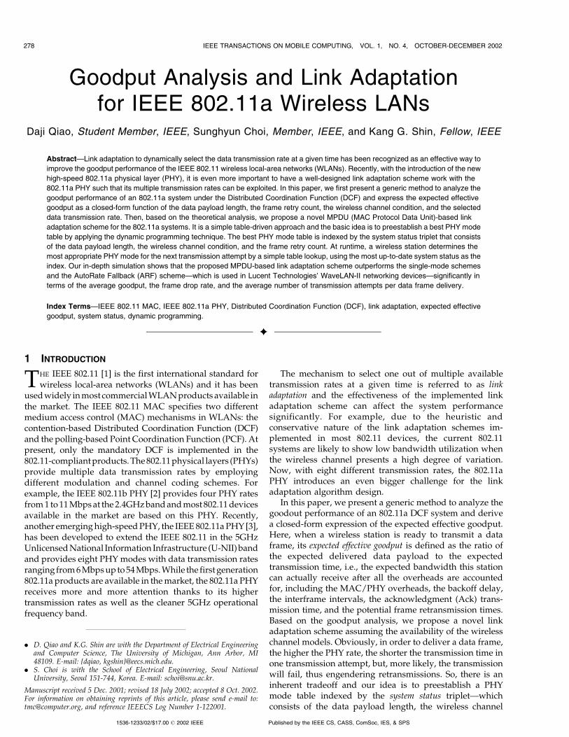
exchange sequence. The timing of successful frame trans-
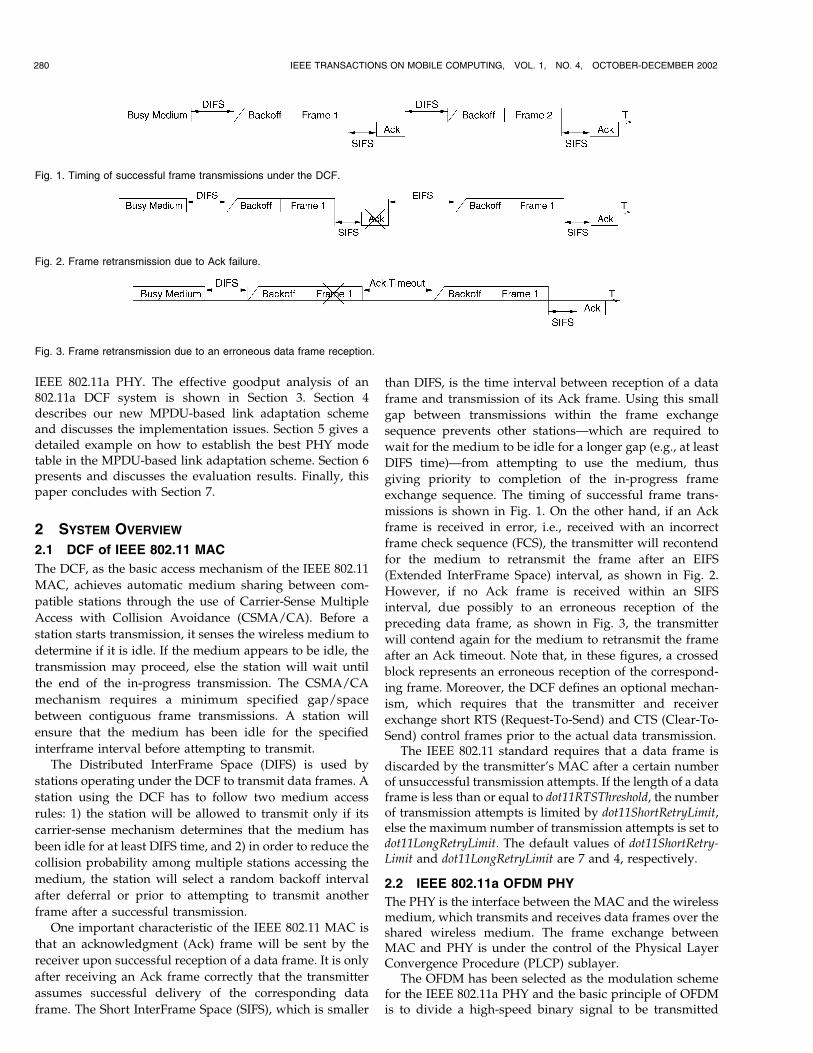
missions is shown in Fig. 1. On the other hand, if an Ack
frame is received in error, i.e., received with an incorrect
frame check sequence (FCS), the transmitter will recontend
for the medium to retransmit the frame after an EIFS
(Extended InterFrame Space) interval, as shown in Fig. 2.
However, if no Ack frame is received within an SIFS
interval, due possibly to an erroneous reception of the
preceding data frame, as shown in Fig. 3, the transmitter
will contend again for the medium to retransmit the frame
after an Ack timeout. Note that, in these figures, a crossed
block represents an erroneous reception of the correspond-
ing frame. Moreover, the DCF defines an optional mechan-
ism, which requires that the transmitter and receiver
exchange short RTS (Request-To-Send) and CTS (Clear-To-
Send) control frames prior to the actual data transmission.The IEEE 802.11 standard requires that a data frame is
discarded by the transmitter’s MAC after a certain numberof unsuccessful transmission attempts. If the length of a dataframe is less than or equal to dot11RTSThreshold, the numberof transmission attempts is limited by dot11ShortRetryLimit,else the maximum number of transmission attempts is set todot11LongRetryLimit. The default values of dot11ShortRetry-Limit and dot11LongRetryLimit are 7 and 4, respectively.
2.2 IEEE 802.11a OFDM PHY
The PHY is the interface between the MAC and the wirelessmedium, which transmits and receives data frames over theshared wireless medium. The frame exchange betweenMAC and PHY is under the control of the Physical LayerConvergence Procedure (PLCP) sublayer.
The OFDM has been selected as the modulation schemefor the IEEE 802.11a PHY and the basic principle of OFDMis to divide a high-speed binary signal to be transmitted
280 IEEE TRANSACTIONS ON MOBILE COMPUTING, VOL. 1, NO. 4, OCTOBER-DECEMBER 2002
Fig. 1. Timing of successful frame transmissions under the DCF.
Fig. 2. Frame retransmission due to Ack failure.
Fig. 3. Frame retransmission due to an erroneous data frame reception.

over a number of low data-rate subcarriers. There are a totalof 52 subcarriers, of which 48 subcarriers carry actual dataand four subcarriers are pilots that facilitate phase trackingfor coherent demodulation. Each low data-rate bit-stream isused to modulate a separate subcarrier from one of thechannels in the 5GHz band. A key feature of the IEEE802.11a PHY is to provide eight PHY modes with differentmodulation schemes and coding rates, making the idea oflink adaptation feasible and important. BPSK, QPSK, 16-QAM, and 64-QAM are the supported modulation schemes.As listed in Table 1, the OFDM system provides a WLANwith capabilities of communicating at 6 to 54 Mbps. Thesupport of transmitting and receiving at the data rates of 6,12, and 24 Mbps is mandatory in the IEEE 802.11a PHY.Forward error correction (FEC) is performed by bitinterleaving and rate-1/2 convolutional coding. The highercode rates of 2/3 and 3/4 are obtained by puncturing theoriginal rate-1/2 code.
3 GOODPUT ANALYSIS OF AN IEEE 802.11a DCFSYSTEM
When a wireless station is ready to transmit a data frame, its
expected effective goodput is defined as the ratio of the expected
delivered data payload to the expected transmission time.
Clearly, depending on the data payload length and the
wireless channel conditions, the expected effective goodput
varies with different transmission strategies. The more
robust the transmission strategy, the more likely the frame
will be delivered successfully within the frame retry limit,
however, with less efficiency. So, there is a tradeoff and the
key idea of link adaptation is to select the most appropriate
transmission strategy such that the frame can be successfully
delivered in the shortest possible transmission time.
Before proceeding to the details of our new link
adaptation scheme, we will first, in this section, analyze
the effective goodput performance of an 802.11a DCF
system and express the expected effective goodput as a
closed-form function of the data payload length (‘), the
frame retry limit (nmax)—which can take the value of
dot11ShortRetryLimit or dot11LongRetryLimit, the wireless
channel conditions (ss) during all the potential transmission
attempts, and the transmission strategy (mm). Here, ss is a
vector of receiver-side SNR (Signal-to-Noise Ratio) values to
quantify the wireless channel conditions, mm is a vector of
PHY mode selections, and both ss and mm are of length nmax.
3.1 MAC/PHY Layer Overheads
As shown in Fig. 4, in the IEEE 802.11 MAC, each MAC dataframe, or MAC Protocol Data Unit (MPDU), consists of thefollowing components:1 MAC header, variable-length infor-mation frame body, and frame check sequence (FCS). The MACoverhead due to the MAC header and the FCS is 28 octets intotal. Fig. 5 illustrates the frame format of an Ack frame,which is 14 octets long.
During the transmission, a PLCP preamble and a PLCPheader are added to an MPDU to create a PLCP ProtocolData Unit (PPDU). The PPDU format of the IEEE 802.11aPHY is shown in Fig. 6, which includes PLCP preamble,PLCP header, MPDU (conveyed from MAC), tail bits, andpad bits, if necessary. The PLCP preamble field, with theduration of tPLCPPreamble, is composed of 10 repetitionsof a short training sequence (0:8�s) and two repetitions ofa long training sequence (4�s). The PLCP header, exceptthe SERVICE field, with the duration of tPLCP_SIG,constitutes a single OFDM symbol, which is transmittedwith BPSK modulation and rate-1/2 convolutional coding.The six “zero” tail bits are used to return the convolu-tional codec to the “zero state” and the pad bits are usedto make the resulting bit string into a multiple of OFDMsymbols. Each OFDM symbol interval, denoted bytSymbol, is 4�s. The 16-bit SERVICE field of the PLCPheader and the MPDU (along with six tail bits and padbits), represented by DATA, are transmitted at the datarate specified in the RATE field. Table 2 lists the relatedcharacteristics for the IEEE 802.11a PHY, where tSlotTime,aCWmin, and aCWmax will be discussed in the followingsection.
Note that, while the data frame MPDUs can betransmitted at any supported data rate, all the controlframes, including the Ack frames, have to be transmitted atone of the rates in the BSS basic rate set2 so that they can beunderstood by all the stations in the same network. Inaddition, an Ack frame will be transmitted at the highestrate in the BSS basic rate set that is less than or equal to therate of the data frame it is acknowledging. For example, if
QIAO ET AL.: GOODPUT ANALYSIS AND LINK ADAPTATION FOR IEEE 802.11A WIRELESS LANS 281
TABLE 1Eight PHY Modes of the IEEE 802.11a PHY
Fig. 4. Frame format of a data frame MPDU.
Fig. 5. Frame format of an Ack frame.
1. Actually, an additional field of “Address 4” appears in the WirelessDistribution System (WDS) data frames being distributed from one accesspoint to another access point. However, since such WDS frames are rarelyused, we do not consider the “Address 4” field in our goodput analysis.Besides, we do not consider the WEP (Wired Equivalent Privacy) option inthis paper, which may introduce an extra eight-octet overhead.
2. Basic Service Set (BSS) is the basic building block of an IEEE 802.11WLAN. It consists of a set of stations controlled by a single coordinationfunction. BSS basic rate set is the set of data rates that all the stations in aBSS will be capable of using to receive/transmit frames from/to thewireless medium. The BSS basic rate set data rates are preset for all thestations in the BSS.

the BSS basic rate set is {6 Mbps, 12 Mbps, 24 Mbps}3 and a
data frame is transmitted at the rate of 18 Mbps, the
corresponding Ack frame will be transmitted at the rate of
12 Mbps.Based on the above analysis, to transmit a frame with
‘ octets data payload over the IEEE 802.11a PHY using PHY
mode m, the transmission duration is:
Tdatað‘;mÞ ¼ tPLCPPreambleþ tPLCP SIG
þ 28þ ð16þ 6Þ=8þ ‘BpSðmÞ
� �� tSymbol
¼ 20�sþ 30:75þ ‘BpSðmÞ
� �� 4�s:
ð1Þ
Note that the Bytes-per-Symbol information for PHY
mode m, BpSðmÞ, is given in Table 1. Similarly, the
transmission duration for an Ack frame using PHY
mode m0 is:
Tackðm0Þ ¼ tPLCPPreambleþ tPLCP SIG
þ 14þ ð16þ 6Þ=8BpSðm0Þ
� �� tSymbol
¼ 20�sþ 16:75
BpSðm0Þ
� �� 4�s:
ð2Þ
3.2 Backoff Delay
The random backoff interval is in the unit of tSlotTime and
this random integer is drawn from a uniform distribution
over the interval ½0; CW �, where CW is the contention
window size and its initial value is aCWmin. In the case of
an unsuccessful transmission, the backoff procedure will
begin at the end of the EIFS interval or the Ack timeout
interval and CW is updated to ½2� ðCW þ 1Þ ÿ 1�. Once
CW reaches aCWmax, it will remain at this value until it is
reset to aCWmin. In the case of a successful transmission,
the backoff procedure will begin at DIFS time after
receiving the Ack frame and the CW value is reset to
aCWmin before the random backoff interval is selected.
The average backoff interval before the ith transmission
attempt or, equivalently, the ðiÿ 1Þth retransmission
attempt, denoted by TbkoffðiÞ, can be calculated by
TbkoffðiÞ
¼ min 2iÿ1 � ðaCWminþ 1Þ ÿ 1; aCWmax½ �2
� tSlotT ime:
ð3Þ
3.3 Effective Goodput Computation
Assume that a frame with ‘ octets data payload is to be
transmitted using PHY mode m over the wireless channel
with condition s. Let m0 denote the PHY mode used for the
corresponding Ack frame transmission and it can be
determined based on m according to the rule specified in
Section 3.1. In the IEEE 802.11 MAC, a frame transmission is
considered successful only upon receiving the correspond-
ing Ack frame correctly. Therefore, the probability of a
successful frame transmission can be calculated by
Ps;xmitð‘; s;mÞ ¼ 1ÿ Pe;datað‘; s;mÞ� �
� 1ÿ Pe;ackðs;m0Þ� �
;
ð4Þ
where Pe;datað‘; s;mÞ and Pe;ackðs;m0Þ are the data error
probability and the Ack error probability, respectively, and
their values vary with different wireless channel models.Now, let’s consider the entire delivery process of the data
frame. Since the maximum number of transmission
attempts to deliver the frame is nmax, we use vector mm to
denote the frame’s transmission strategy, i.e., the PHY
mode selections for all the potential transmission attempts.
Besides, we use mn to denote the PHY mode selected for the
nth transmission attempt. Similarly, sn represents the
wireless channel condition during the nth transmission
attempt and ss ¼ fs1; � � � ; snmaxg is the wireless channel
condition vector. The probability of a successful frame
delivery within the retry limit can then be calculated by
282 IEEE TRANSACTIONS ON MOBILE COMPUTING, VOL. 1, NO. 4, OCTOBER-DECEMBER 2002
Fig. 6. PPDU frame format of the IEEE 802.11a OFDM PHY.
3. {6 Mbps, 12 Mbps, 24 Mbps} is the set of the IEEE 802.11a mandatorydata rates, and it will be assumed to be the BSS basic rate set in our exampleand simulation.
TABLE 2IEEE 802.11a OFDM PHY Characteristics

Psuccð‘; ss; mmÞ ¼ 1ÿYnmaxi¼1
½1ÿ Ps;xmitð‘; si;miÞ�: ð5Þ
By referring to Fig. 1, each successful frame transmission
duration is equal to a backoff delay, plus the data
transmission time, plus a SIFS time, plus the Ack transmis-
sion time, and plus a DIFS time. However, whenever the
frame transmission fails, the station has to wait for an EIFS
interval or an Ack timeout period, and then execute a
backoff procedure before the retransmission (see Figs. 2 and
3). According to the Specification and Description Language
formal description of the IEEE 802.11 MAC operation [1], an
EIFS interval is equal to a SIFS time plus a DIFS time plus
the Ack transmission time at the most robust 6 Mbps and an
Ack timeout is equal to a SIFS time plus an Ack
transmission time plus a Slot time. Therefore, the average
transmission duration of the data frame, if delivered
successfully with the transmission strategy mm, can be
calculated by4
Dsuccj‘;ss;mm ¼Xnmaxn¼1
P ½njsucc�ð‘; ss; mmÞ
�(Xn
i¼2
DwaitðiÞ þ TbkoffðiÞ þ Tdatað‘;miÞ� �
þ Tbkoffð1Þ þ Tdatað‘;m1Þ þ tSIFSTime
þ Tackðm0nÞ þ tDIFSTime);
ð6Þ
where P ½njsucc�ð‘; ss; mmÞ and DwaitðiÞ are the conditional
probability that the data frame is successfully delivered at
the nth transmission attempt and the average waiting time
before the ith transmission attempt, respectively, and they
can be calculated by
P ½njsucc�ð‘; ss; mmÞ
¼ Ps;xmitð‘; sn;mnÞ �Qnÿ1
i¼1 ½1ÿ Ps;xmitð‘; si;miÞ�Psuccð‘; ss; mmÞ
ð7Þ
and
DwaitðiÞ ¼Pe;datað‘; siÿ1;miÿ1Þ
1ÿ Ps;xmitð‘; siÿ1;miÿ1Þ� tSIFSTimeþ Tackðm0iÿ1Þ þ tSlotT ime� �þ
1ÿ Pe;datað‘; siÿ1;miÿ1Þ� �
� Pe;ackðsiÿ1;m0iÿ1Þ
1ÿ Ps;xmitð‘; siÿ1;miÿ1Þ��tSIFSTimeþ Tackðm0iÿ1Þ þ tSIFSTimeþ Tackð1Þ þ tDIFSTime
�:
ð8Þ
Tdatað�Þ, Tackð�Þ, and Tbkoffð�Þ are given by (1), (2), and (3),
respectively. On the other hand, the average time wasted to
attempt transmission of the data frame nmax times in error is
given by
Dfailj‘;ss;mm
¼Xnmaxi¼1
TbkoffðiÞ þ Tdatað‘;miÞ þ Dwaitðiþ 1Þ� �
:ð9Þ
The expected effective goodput can then be calculated by
Gð‘; ss; mmÞ ¼ ‘P1k¼0
�ð1ÿPsuccð‘;ss;mmÞÞk �Psuccð‘;ss;mmÞ�ðk�Dfailj‘;ss;mmþDsuccj‘;ss;mmÞ
�¼ ‘
1ÿPsuccð‘;ss;mmÞPsuccð‘;ss;mmÞ � Dfailj‘;ss;mm þDsuccj‘;ss;mm
¼ Psuccð‘;ss;mmÞ�‘ð1ÿPsuccð‘;ss;mmÞÞ�Dfailj‘;ss;mmþPsuccð‘;ss;mmÞ�Dsuccj‘;ss;mm
¼ E½data�ð‘; ss; mmÞE½Ddata�ð‘; ss; mmÞ
;
ð10Þ
which is based on the fact that, with probability,
ð1ÿ Psuccð‘; ss; mmÞÞk � Psuccð‘; ss; mmÞh i
;
there is a successful data frame delivery within the retry limitafter dropping the previous k frames. It can also beinterpreted as follows: The expected effective goodput isequal to the ratio of the expected delivered data payload tothe expected transmission time. Note that, under theconstraint of the frame retry limit, the successfully delivereddata payload is no longer a fixed value of ‘. It is actually atwo-value random variable and can take the value of ‘—ifdelivery succeeds, with probability Psuccð‘; ss; mmÞ—or 0 ifdelivery fails. So, E½data�ð‘; ss; mmÞ ¼ Psuccð‘; ss; mmÞ � ‘ is theexpected data payload delivered with the transmissionstrategy mm. Similarly, E½Ddata�ð‘; ss; mmÞ is the expectedtransmission time spent on the frame delivery attempt,irrespective of whether it is successful or not.
4 THE MPDU-BASED LINK ADAPTATION SCHEME
From the above goodput analysis, we observe that, todeliver a data frame over a wireless channel, the higherthe PHY modes that are used ðmm "Þ, the shorter theexpected transmission time will be ðE½Ddata� #Þ, but theless likely the delivery will succeed within the frame retrylimit ðPsuccð‘; ss; mmÞ #Þ. So, for any given set of wirelesschannel conditions, there exists a corresponding set ofPHY modes that maximize the expected effective good-put. Such a set of PHY modes, denoted by mm�, is calledthe best transmission strategy for the data frame deliveryunder the given wireless channel conditions.
Our MPDU-based link adaptation scheme to be pre-
sented in this section is an enhancement of the simple
MSDU-based adaptive PHY mode selection scheme that we
originally proposed in [11]. For completeness, we briefly
describe the MSDU-based adaptive PHY mode selection
scheme, present some numerical results, and discuss its
problems and limitations.
4.1 MSDU-Based Adaptive PHY Mode Selection
The MSDU-based adaptive PHY mode selection scheme is
based on a simplified goodput analysis, which assumes the
constant wireless channel condition throughout the entire
frame delivery period. As the name indicates, one of the key
features of this scheme is that, after a wireless station makes
QIAO ET AL.: GOODPUT ANALYSIS AND LINK ADAPTATION FOR IEEE 802.11A WIRELESS LANS 283
4. The air propagation delay is neglected in the computations because itis very small (e.g., 1
3�s, assuming 100-meter transmission range) evencompared to tSlotTime (9�s), thus having almost no effect on the goodputanalysis.

the PHY mode selection and starts transmitting, the selected
PHY mode will be used for all the potential retransmissions,
i.e., mm� ¼ fm�;m�; � � � ;m�g.Figs. 7a and 7b show the numerical results of the effective
goodput, according to the simplified goodput analysis and
assuming the AWGN (Additive White Gaussian Noise)
wireless channel noise model, for different PHY mode
selections with MSDU size of 2,000 octets and 200 octets,
respectively. As expected, the higher rate PHY modes result
in better goodput performance in the high SNR range, while
the lower rate PHY modes result in better goodput
performance in the low SNR range. One interesting
observation is that the effective goodput using PHY mode
3 (QPSK modulation with rate-1/2 coding) is always
better than that of PHY mode 2 (BPSK modulation with
rate-3/4 coding) under all SNR conditions for both frame
sizes. The rationale behind this is that, although QPSK has
worse error performance than BPSK, the worse perfor-
mance of the rate-3/4 convolutional code compared to the
rate-1/2 convolutional code has more dominant effects.
Therefore, in the presence of PHY mode 3, PHY mode 2
may not be a good choice for data delivery services.
Another observation from Fig. 7 is that a smaller MSDU
size results in lower effective goodputs due to the fixed
amount of MAC/PHY layer overheads for each transmis-
sion attempt. Fig. 8 shows the maximum effective goodput
and the corresponding PHY mode selections for different
SNR values. Notice that PHY mode 2 is not part of the
selections, which is consistent with the fact that PHY mode
2 results in a smaller effective goodput than PHY mode 3
under all SNR conditions, as shown in Fig. 7.
Although the MSDU-based adaptive PHY mode selec-
tion scheme is simple and easy to deploy, it has some
limitations. First, since the wireless channel is known to be
error-prone and time-varying, it is unrealistic to assume a
constant channel condition over the (long) frame delivery
period that includes all the retransmissions. Second, since
284 IEEE TRANSACTIONS ON MOBILE COMPUTING, VOL. 1, NO. 4, OCTOBER-DECEMBER 2002
Fig. 7. Effective goodput versus SNR. (a) MSDU size: 2,000 octets and (b) MSDU size: 200 octets.
Fig. 8. MSDU-based adaptive PHY mode selection to improve the effective goodput. (a) MSDU size: 2,000 octets and (b) MSDU size: 200 octets.
this scheme selects the PHY mode to deliver a data frame
before the original transmission starts and sticks with this
PHY mode for all the retransmissions, it cannot adapt
quickly to the fast-changing wireless channel.
4.2 MPDU-Based Link Adaptation
Recognizing the limitations of the MSDU-based adaptive
PHY mode selection scheme, we propose a new MPDU-
based link adaptation scheme, which features two major
enhancements over the MSDU-based scheme. First, it makes
a more realistic assumption on the wireless channel
variation that the channel condition remains unchanged
over a single MPDU transmission period, which is much
shorter than the entire MSDU delivery period. Second, in
the middle of an MSDU delivery, the wireless station could
adapt the PHY mode for the next transmission attempt if
there is any variation of the wireless channel condition, i.e.,
mm� ¼ fm�1; m�2; � � � ;m�nmaxg, where m�1; m�2; � � � ; and m�nmax
could be different. Since there are only finite choices for the
PHY mode and the frame retry limit is also finite, we can
use exhaustive search to find mm� for each set of wireless
channel conditions. Then, at runtime, based on the predic-
tion of the channel conditions during each transmission
attempt, the best transmission strategy can be determined
by a table lookup. This idea may sound attractive, but it
works well only with the perfect knowledge on the wireless
channel variation throughout the entire MSDU delivery
period. Unfortunately, the wireless channel variation is
unpredictable. Although there have been many schemes
proposed to estimate or predict the wireless channel
variation, none of them can guarantee accurate predictions.
So, instead, motivated by [12] and [13], we solve the
problem of finding mm� from a different angle—using the
dynamic programming technique.
4.2.1 Preestablished PHY Mode Table
The basic idea of our MPDU-based link adaptation schemeis that the wireless station computes offline a table of PHYmodes indexed by the system status and each entry of thetable is the best PHY mode in the sense of maximizing theexpected effective goodput under the corresponding systemstatus. The system status is characterized by a triplet (‘; s; n),where ‘ is the data payload length, s is a receiver-side SNRvalue to quantify the wireless channel condition, and nstands for the nth transmission attempt or, equivalently, thenth frame retry count. This table is used at runtime todetermine the best PHY mode for the next MPDUtransmission attempt. The table entries are computed asfollows.
First, consider the special case when n ¼ nmax, i.e., whenthe next transmission attempt is the last chance to deliverthe current frame. Obviously, the frame delivery issuccessful only if both data transmission and Ack transmis-sion are error-free or result in correctable errors. Therefore,similarly to (10), the expected effective goodput, if PHYmode m is used, can be calculated by
Gð‘; s;m; nmaxÞ ¼E½data�ð‘; s;m; nmaxÞE½Ddata�ð‘; s;m; nmaxÞ
; ð11Þ
where
E½data�ð‘; s;m; nmaxÞ ¼ Ps;xmitð‘; s;mÞ � ‘; ð12Þ
and
E½Ddata�ð‘; s;m; nmaxÞ ¼TbkoffðnmaxÞ þ Tdatað‘;mÞ þ tSIFSTimeþ Tackðm0Þþ Ps;xmitð‘; s;mÞ � tDIFSTimeþ ½1ÿ Ps;xmitð‘; s;mÞ� � Dwaitðnmax þ 1Þ:
ð13Þ
Ps;xmitð�Þ, Tbkoffð�Þ, Tdatað�Þ, Tackð�Þ, and Dwaitð�Þ are given by
(4), (3), (1), (2), and (8), respectively. Consequently, the best
PHY mode to use for the last transmission attempt and the
corresponding maximum expected effective goodput are,
respectively,
m�ð‘; s; nmaxÞ ¼ arg max1�m�8
Gð‘; s;m; nmaxÞ; ð14Þ
and
G�ð‘; s; nmaxÞ ¼ Gð‘; s;m�ð‘; s; nmaxÞ; nmaxÞ¼ max
1�m�8Gð‘; s;m; nmaxÞ: ð15Þ
Now, let’s consider the general case when 1 � n < nmax.
Assume that PHY mode m is selected for the nth
transmission attempt. The transmission is considered
successful only upon receiving a positive acknowledgment;
otherwise, the station has to recontend for the medium to
retransmit the frame. We use fRjSðrjsÞ to denote the
conditional probability density function that the wireless
channel condition becomes r during the next transmission
attempt, i.e., the system status becomes (‘; r; nþ 1), given
the current wireless channel condition of s. Notice that this
density function varies with elapsed time between two
transmission attempts and different wireless channel varia-
tion models can be characterized by different fRjSðrjsÞs.
Based on the above observations, we can construct the
following recursive relation:
Gð‘; s;m; nÞ ¼ E½data�ð‘; s;m; nÞE½Ddata�ð‘; s;m; nÞ
; ð16Þ
where
E½data�ð‘; s;m; nÞ¼ Ps;xmitð‘; s;mÞ � ‘þ 1ÿ Ps;xmitð‘; s;mÞ
� ��Z 1ÿ1
fRjSðrjsÞ � E½data�ð‘; r;m�ð‘; r; nþ 1Þ; nþ 1Þdr;ð17Þ
and
E½Ddata�ð‘; s;m; nÞ ¼TbkoffðnÞ þ Tdatað‘;mÞ þ tSIFSTimeþ Tackðm0Þþ Ps;xmitð‘; s;mÞ � tDIFSTime
þ ½1ÿ Ps;xmitð‘; s;mÞ� �(Dwaitðnþ 1Þ þ
Z 1ÿ1
fRjSðrjsÞ
� E½Ddata�ð‘; r;m�ð‘; r; nþ 1Þ; nþ 1Þdr);
ð18Þ
QIAO ET AL.: GOODPUT ANALYSIS AND LINK ADAPTATION FOR IEEE 802.11A WIRELESS LANS 285

respectively. Similarly, the best PHY mode to use for the nth
transmission attempt and the corresponding maximum
expected effective goodput are
m�ð‘; s; nÞ ¼ arg max1�m�8
Gð‘; s;m; nÞ; ð19Þ
and
G�ð‘; s; nÞ ¼ Gð‘; s;m�ð‘; s; nÞ; nÞ ¼ max1�m�8
Gð‘; s;m; nÞ; ð20Þ
respectively. Therefore, by using the special case of n ¼nmax as the boundary condition, we have fully specified the
computation of the best PHY modes for different system
status by (11), (14), (16), and (19).
4.2.2 Runtime Execution
Fig. 9 shows the pseudocoded algorithm of our proposed
MPDU-based link adaptation scheme. Before running the
program, the wireless station computes the best PHY mode
for each set of data payload length (‘), SNR value (s), and
frame retry count (n). Thus, a best PHY mode table is
preestablished and ready for runtime use. The counts
succ_count for delivered frames and fail_count for dropped
frames are both reset to 0 and the retry count (ncurr) for the
frame at the header of the data queue is set to 1. At runtime,
the wireless station monitors the wireless channel condition
and determines the current system status. Then, the
wireless station selects the best PHY mode (mncurr ) for the
next transmission attempt by a simple table lookup.
Whenever an Ack frame is received correctly within the
Ack timeout, ncurr is reset to 1 and succ_count is increased;
else ncurr :¼ ncurr þ 1. As shown in the pseudocode, if a
frame cannot be successfully delivered after nmax transmis-
sion attempts, it will be dropped and fail_count is increased,
and ncurr is reset to 1 for the next frame waiting in the data
queue. Notice that, since the best PHY mode table is
computed offline, there is no extra runtime computational
cost for the proposed MPDU-based link adaptation scheme.
4.2.3 Implementation Issues
Fig. 10 shows a system architecture to implement theproposed MPDU-based link adaptation scheme. The linkadaptor module provides two levels of functionality. First,the link adaptor monitors the wireless channel condition,estimates the receiver-side SNR value, and determines thecurrent system status. The SNR value at the receiver side (indB) is actually equal to the transmit power level (in dBm)minus the path loss (in dB) minus the noise level observedby the receiver (in dBm). Therefore, to estimate the receiver-side SNR value, it is equivalent to estimate the path lossbetween the transmitter and the receiver and we havedeveloped a simple and novel scheme for this purpose. Fordetails about this path loss estimation scheme, refer to [14].Second, the link adaptor looks up the prebuilt best PHYmode table to determine the best transmission strategy forthe next transmission attempt. The two functionalities arerepresented as the SNR estimator and the PHY mode selector,respectively.
One important aspect of this architecture is that theimplementation of the link adaptor is transparent to thehigher layers, which makes it compatible to the existingnetwork or higher layer applications. Besides, the basic ideaof link adaptation is to take advantage of differentmodulation schemes and FEC capabilities provided by the802.11a PHY and no additional error correction codes needto be implemented. Therefore, the implementation of thelink adaptor module should be fairly simple, thus facilitat-ing its deployment.
5 AN EXAMPLE OF THE BEST PHY MODE TABLE
As described in the previous section, the key idea of ourproposed MPDU-based link adaptation scheme is toestablish a best PHY mode table indexed by the systemstatus before the communication starts. In order to do so, awireless station needs the following information a priori: awireless channel noise model that determines the errorperformances of the PHY modes and a conditional prob-ability density function, fRjSðrjsÞ, to model the wirelesschannel variation. There have been many papers [15], [16],[17], [18], [19] dealing with the problem of building accurate
286 IEEE TRANSACTIONS ON MOBILE COMPUTING, VOL. 1, NO. 4, OCTOBER-DECEMBER 2002
Fig. 9. The MPDU-based link adaptation algorithm. Fig. 10. System architecture for link adaptation.

wireless channel models, which, however, is not the focusof this paper. Our contribution is to propose a simple andeffective link adaptation scheme by assuming the avail-ability of such wireless channel models.
In this section, we give a detailed example of how toestablish the best PHY mode table and, for simplicity, weassume an AWGN channel noise model and a two-statediscrete time Markov chain channel variation model. Wecan establish the best PHY mode tables with other morerealistic channel models as well, although the computationsare much more complicated.
5.1 Error Performances of PHY Modes over theAWGN Channel
5.1.1 Bit Error Probability
The symbol error probability for an M-ary (M ¼ 4; 16; 64)Quadrature Amplitude Modulation (QAM) [20] with theaverage SNR per symbol, s, can be calculated by
PMðsÞ ¼ 1ÿ 1ÿ P ffiffiffiffiMp ðsÞ
h i2; ð21Þ
where
P ffiffiffiffiMp ðsÞ ¼ 2 � 1ÿ 1ffiffiffiffiffi
Mp
� ��Q
ffiffiffiffiffiffiffiffiffiffiffiffiffiffiffiffiffiffiffi3
M ÿ 1� s
r !ð22Þ
is the symbol error probability for theffiffiffiffiffiMp
-ary PulseAmplitude Modulation (PAM). The Q-function is defined as
QðxÞ ¼Z 1x
1ffiffiffiffiffiffi2�p eÿy
2=2dy: ð23Þ
With a Gray coding, the bit error probability for an M-aryQAM can be approximated by
PðMÞb ðsÞ � 1
log2 M� PMðsÞ: ð24Þ
Note that the 4-ary QAM and Quadrature Phase ShiftKeying (QPSK) modulation are identical. For Binary PhaseShift Keying (BPSK) modulation, the bit error probability isthe same as the symbol error probability, which is given by
Pð2Þb ðsÞ ¼ P2ðsÞ ¼ Q
ffiffiffiffiffi2sp� �
: ð25Þ
Obviously, the error performance of a modulation schemevaries with different SNR values.
5.1.2 Packet Error Probability
In [21], an upper bound was given on the packet errorprobability under the assumption of binary convolutionalcoding and hard-decision Viterbi decoding with indepen-dent errors at the channel input. For an h-octet long packetto be transmitted using PHY mode m, this bound is
Pme ðh; sÞ � 1ÿ 1ÿ Pm
u ðsÞ� �8h
; ð26Þ
where the union bound Pmu ðsÞ of the first-event error
probability is given by
Pmu ðsÞ ¼
X1d¼dfree
ad � PdðsÞ; ð27Þ
where dfree is the free distance of the convolutional code
selected in PHY mode m, ad is the total number of error
events of weight d, and PdðsÞ is the probability that an
incorrect path at distance d from the correct path being
chosen by the Viterbi decoder. When the hard-decision
decoding is applied, PdðsÞ is given by
PdðsÞ ¼
Pdk¼ðdþ1Þ=2
dk
ÿ �� �k � ð1ÿ �Þdÿk; if d is odd;
12 �
dd=2
� �� �d=2 � ð1ÿ �Þd=2
þPd
k¼d=2þ1dk
ÿ �� �k � ð1ÿ �Þdÿk; if d is even;
8>>><>>>:ð28Þ
where � is the bit error probability for the modulation
scheme selected in PHY mode m and is given by (24) or (25).
The value of ad can be obtained either from the transfer
function or by a numerical search [22].Therefore, Pe;datað‘; s;mÞ, the data error probability, and
Pe;ackðs;m0Þ, the Ack error probability, used in Section 3 to
compute Ps;xmitð‘; s;mÞ, the probability of a successful
frame transmission, can be calculated by
Pe;datað‘; s;mÞ¼ 1ÿ 1ÿ P 1
e ð24=8; sÞ� �
� 1ÿ Pme ð28þ ð16þ 6Þ=8þ ‘; sÞ
� �¼ 1ÿ 1ÿ P 1
e ð3; sÞ� �
� 1ÿ Pme ð30:75þ ‘; sÞ
� �;
ð29Þ
and
Pe;ackðs;m0Þ
¼ 1ÿ 1ÿ P 1e ð24=8; sÞ
� �� 1ÿ Pm0
e ð14þ ð16þ 6Þ=8; sÞh i
¼ 1ÿ 1ÿ P 1e ð3; sÞ
� �� 1ÿ Pm0
e ð16:75; sÞh i
;
ð30Þ
respectively. Here, P 1e ð3; sÞ is the packet error probability
of the PLCP SIGNAL field because it is 24-bit long and
always transmitted with BPSK modulation and rate-1/2
convolutional coding, i.e., PHY mode 1. P 1e ð�Þ, Pm
e ð�Þ, and
Pm0e ð�Þ are calculated by (26).
5.2 Wireless Channel Variation Model
Fig. 11 shows a two-state discrete time Markov chain to
model the wireless channel variation. The wireless channel
could be in either a good or bad state. When the wireless
channel is in the good state, the corresponding SNR at each
time instant is taken from a uniform distribution in the
range of 15 to 30 dB, and when the wireless channel is in the
bad state, the SNR value is drawn from the range of 0 to
15 dB. The time spent in the good and bad states are taken
from exponential distributions with rates 1�g
and 1�b
,
respectively. Therefore, the state transition probabilities
tg;b and tb;g are equal to �b�gþ�b and
�g�gþ�b , respectively.
Different values of tb;g correspond to different wireless
channel variation patterns. For example, if tb;g is close to
0 ð1Þ, the wireless channel tends to stay in the bad (good)
state for most of the time.
QIAO ET AL.: GOODPUT ANALYSIS AND LINK ADAPTATION FOR IEEE 802.11A WIRELESS LANS 287
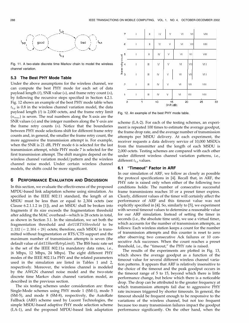
5.3 The Best PHY Mode Table
Under the above assumptions for the wireless channel, wecan compute the best PHY mode for each set of datapayload length (‘), SNR value (s), and frame retry count (n),by following the recursive steps specified in Section 4.2.1.Fig. 12 shows an example of the best PHY mode table whentb;g is 0.8 in the wireless channel variation model, the datapayload length (‘) is 2,000 octets, and the frame retry limit(nmax) is seven. The real numbers along the X-axis are theSNR values (s) and the integer numbers along the Y-axis arethe frame retry counts (n). Notice that the boundariesbetween PHY mode selections shift for different frame retrycounts and, in general, the smaller the frame retry count, themore aggressive the transmission attempt is. For example,when the SNR is 21 dB, PHY mode 6 is selected for the lasttransmission attempt, while PHY mode 7 is selected for thefirst transmission attempt. The shift margins depend on thewireless channel variation model/pattern and the wirelesschannel noise model. Under certain wireless channelmodels, the shifts could be more significant.
6 PERFORMANCE EVALUATION AND DISCUSSION
In this section, we evaluate the effectiveness of the proposedMPDU-based link adaptation scheme using simulation. Asspecified in the IEEE 802.11 standard, the length of anMSDU must be less than or equal to 2,304 octets (seeClause 6.2.1.1.2 in [1]), and an MSDU shall be broken intofragments if its size exceeds the fragmentation thresholdafter adding the MAC overhead—which is 28 octets in total,as shown in Section 3.1. In the simulation, we set both thefragmentation threshold and dot11RTSShreshold to be2; 332 ð¼ 2; 304þ 28Þ octets; therefore, each MSDU is trans-mitted without fragmentation or RTS/CTS support and themaximum number of transmission attempts is seven (thedefault value of dot11ShortRetryLimit). The BSS basic rate setis the set of the IEEE 802.11a mandatory data rates, i.e.,{6 Mbps, 12 Mbps, 24 Mbps}. The eight different PHYmodes of the IEEE 802.11a PHY and the related parametersused in the simulation are listed in Tables 1 and 2,respectively. Moreover, the wireless channel is modeledby the AWGN channel noise model and the two-statediscrete time Markov chain channel variation model, asdescribed in the previous section.
The six testing schemes under consideration are: threeSingle-Mode schemes using PHY mode 1 (SM-1), mode 5(SM-5), and mode 8 (SM-8), respectively, the AutoRateFallback (ARF) scheme used by Lucent Technologies, thesimple MSDU-based adaptive PHY mode selection scheme(LA-1), and the proposed MPDU-based link adaptation
scheme (LA-2). For each of the testing schemes, an experi-ment is repeated 100 times to estimate the average goodput,the frame drop rate, and the average number of transmissionattempts per MSDU delivery. At each experiment, thereceiver requests a data delivery service of 10,000 MSDUsfrom the transmitter and the length of each MSDU is2,000 octets. Testing schemes are compared with each otherunder different wireless channel variation patterns, i.e.,different tb;g values.
6.1 “Timeout” Factor in ARF
In our simulation of ARF, we follow as closely as possiblethe protocol specifications in [4]. Recall that, in ARF, thePHY rate is raised only when either of the following twoconditions holds: The number of consecutive successfulframe transmissions reaches 10 or a preset timer expires.Clearly, different values of the timer will certainly affect theperformance of ARF and this timeout value was notexplicitly specified in [4]. So, similarly to [5], we experimentwith several timeout values to determine a reasonable valuefor our ARF simulation. Instead of setting the timer inseconds (i.e., the absolute time unit), we use a virtual timer,which accounts for the number of transmission attempts, asfollows: Each wireless station keeps a count for the numberof transmission attempts and this counter is reset to zeroafter observing two consecutive Ack failures or 10 con-secutive Ack successes. When the count reaches a presetthreshold, i.e., the “timeout,” the PHY rate is raised.
The results of the experiments are plotted in Fig. 13,which shows the average goodput as a function of thetimeout value for several different wireless channel varia-tion patterns. It appears that ARF is relatively insensitive tothe choice of the timeout and the peak goodput occurs inthe timeout range of 5 to 15, beyond which there is littleperformance change, but below which there is a noticeabledrop. The drop can be attributed to the greater frequency atwhich transmission attempts fail due to aggressive PHYrate increases triggered by shorter timeouts. In general, thetimeout should be frequent enough to be responsive to thevariations of the wireless channel, but not too frequentbecause too many transmission failures impact the goodputperformance significantly. On the other hand, when the
288 IEEE TRANSACTIONS ON MOBILE COMPUTING, VOL. 1, NO. 4, OCTOBER-DECEMBER 2002
Fig. 11. A two-state discrete time Markov chain to model the wireless
channel variation.
Fig. 12. An example of the best PHY mode table.

timeout is less than (equal to) 10, the PHY rate increases dueto 10 consecutive transmission successes, which is one ofthe kernel ideas of the ARF scheme, never (rarely) occurs.Therefore, it is not appropriate to use a timeout of less thanor equal to 10. Based on the above observations, we choosethe timeout value to be 15 in our ARF simulation.
6.2 Performance Evaluation
First, the testing schemes are evaluated using the averagegoodput and the results under different wireless channelvariation patterns are plotted in Fig. 14. Clearly, thegoodput varies with different channel variation patternsand the link adaptation schemes outperform the single-mode schemes in most cases. We have several observationsfrom this figure.
SM-1 is the most conservative scheme of all. It uses themost robust PHY mode (i.e., PHY Mode 1) for all thetransmission attempts. When the wireless channel tends tostay in the good state for most of the time, i.e., when tb;g isclose to 1.0, SM-1 results in the lowest average goodputbecause of the limited transmission rate of PHY mode 1.However, since PHY mode 1 is the most robust, mostframes are successfully delivered with a very few transmis-sion attempts, regardless of the wireless channel variationpattern. As a result, we observe an almost flat goodputcurve for SM-1. On the other hand, SM-8 is the mostaggressive scheme, which uses PHY mode 8 for all thetransmission attempts. To no one’s surprise, SM-8 has thelowest average goodput when the wireless channel tends tostay in the bad state for most of the time, i.e., when tb;g isclose to 0.0. This is because the poorest error correctingcapability of PHY mode 8 results in a large number of frameretransmissions and delivery failures. For the extreme caseof tb;g ¼ 0:0, all the transmission attempts fail and theaverage goodput drops to zero. Another single-modescheme, SM-5, can be viewed as a compromise betweenSM-1 and SM-8.
The goodput results for three link adaptation schemes areplotted as the cross points (ARF), the circle points (LA-1),and the triangle points (LA-2) in Fig. 14. As expected, all ofthem result in higher goodputs than SM-1 and SM-8 because
of their adaptive use of efficient high PHY modes in the goodstate and robust low PHY modes in the bad state. ARFappears to be the most conservative link adaptation schemeof the three. One interesting observation is that, if a linkadaptation scheme is not designed carefully—e.g., ARF ispurely heuristic and LA-1 cannot adjust the PHY modebetween frame retransmissions, then it might even result in aworse performance than some judiciously selected single-mode schemes. For example, when tb;g is between 0.5 and 0.7,SM-5 outperforms both ARF and LA-1. On the other hand,since LA-2 is MPDU-based and is able to adapt the PHYmode for each transmission attempt according to the mostup-to-date system status, it is guaranteed to have the bestperformance. As shown in Fig. 14, LA-2 is significantlybetter than ARF and outperforms LA-1 by about 10 percentin terms of the average goodput.
Second, the testing schemes are compared using theframe drop rate or, equivalently, the average number ofdropped frames out of the 10,000 frames waiting fordelivery. The results are listed in Table 3. Notice thatSM-1, ARF, and LA-2 are all perfect in terms of frame drop.However, the rationales are different. Unlike SM-1, whichsticks with the most robust PHY mode, or ARF, whichapplies a conservative policy and is reluctant to increase the
QIAO ET AL.: GOODPUT ANALYSIS AND LINK ADAPTATION FOR IEEE 802.11A WIRELESS LANS 289
Fig. 13. Goodput comparison of ARF for various “timeout” values. Fig. 14. Goodput comparison of the testing schemes.
TABLE 3Comparison for Average Number of Dropped MSDUs
PHY rate, LA-2 presents the excellent frame drop perfor-
mance due to its quick adaptability to the variations of the
wireless channel. We have two observations about SM-5,
SM-8, and LA-1. First, in general, the average number of
dropped frames increases as the wireless channel gets
worse for these three schemes. In particular, when tb;g ¼ 0:0,
SM-8 results in 10,000 dropped frames, which is consistent
with the zero average goodput observed in Fig. 14. Second,
LA-1 results in fewer dropped frames when tb;g ¼ 0:0 rather
than when tb;g ¼ 0:1 or 0:2. This counterintuitive observa-
tion is surprising at first sight, but rather reasonable. Recall
that LA-1 is unable to adjust the PHY mode for retransmis-
sions when the wireless channel condition fluctuates. So,
the frame drop performance of LA-1 is affected by not only
the wireless channel condition, but the wireless channel
variation as well. When tb;g ¼ 0:0, since the wireless channel
tends to stay in the bad state for most of the time, there are
relatively fewer SNR variations than when tb;g ¼ 0:1 or 0:2.
As a result, LA-1 shows better frame drop performance
under this wireless channel variation pattern. However,
since the wireless channel can get really bad in this case, we
still observe a significant number of dropped frames.
Our previous observations and conclusions about the six
testing schemes can be further justified by comparing the
average number of transmission attempts per MSDU
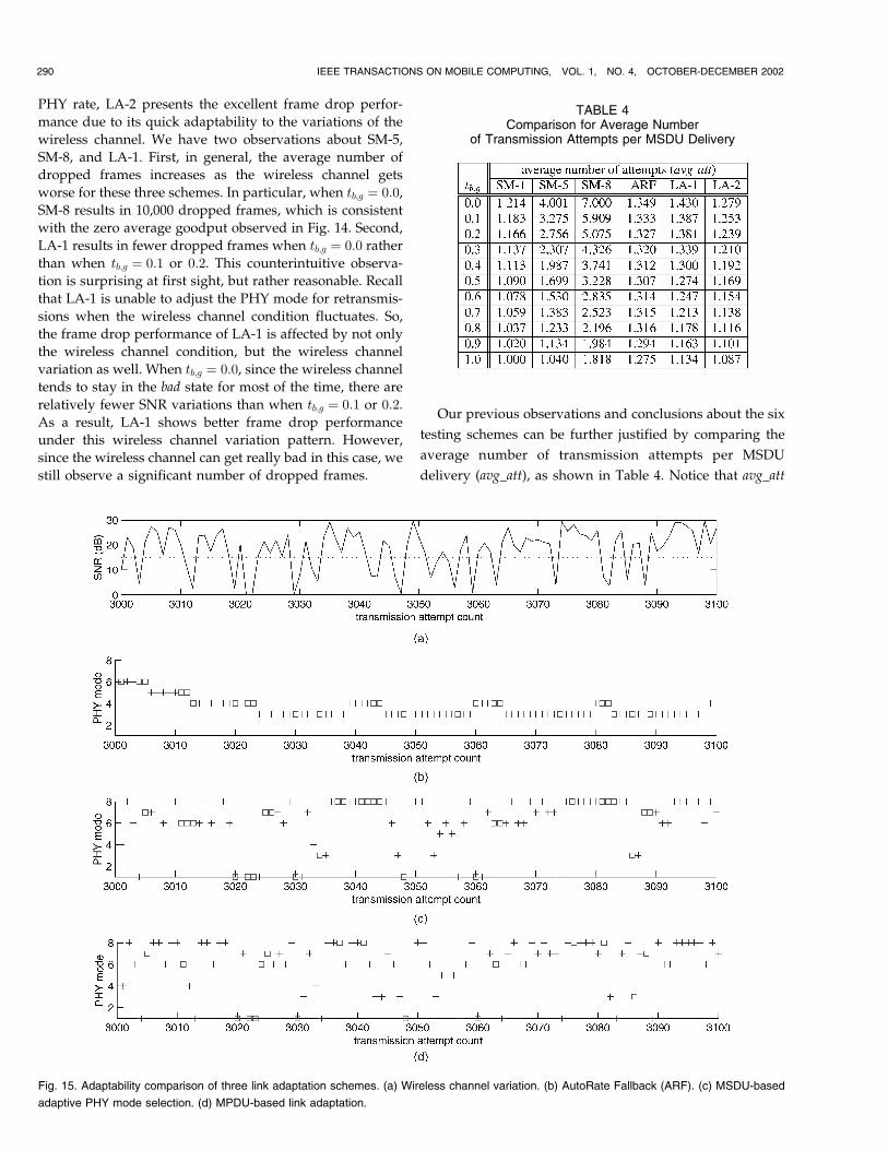
delivery (avg_att), as shown in Table 4. Notice that avg_att
290 IEEE TRANSACTIONS ON MOBILE COMPUTING, VOL. 1, NO. 4, OCTOBER-DECEMBER 2002
TABLE 4Comparison for Average Number
of Transmission Attempts per MSDU Delivery
Fig. 15. Adaptability comparison of three link adaptation schemes. (a) Wireless channel variation. (b) AutoRate Fallback (ARF). (c) MSDU-based
adaptive PHY mode selection. (d) MPDU-based link adaptation.

varies sharply for the single-mode schemes, while linkadaptation schemes have smaller avg_att values which donot change much with the wireless channel variationpattern. This is reasonable since one of the kernel ideas oflink adaptation is to select more robust PHY modes whenthe wireless channel condition gets worse.
Finally, we use Fig. 15 to illustrate the behavior of thethree testing link adaptation schemes and the fast adapt-ability of LA-2 to the wireless channel variations can be seenmore clearly in this figure. The wireless channel variationpattern used to produce the results is tb;g ¼ 0:8. Fig. 15ashows the SNR values observed during each of thetransmission attempts from #3,000 to #3,100 and the PHYmode selections by ARF, LA-1, and LA-2 are shown inFigs. 15b, 15c, and 15d, respectively. Note that, in thesefigures, the cross points stand for the successful transmis-sion attempts and a square point represents a transmissionfailure. We have two observations. First, ARF is slow toadapt to the changes in SNR, as evidenced by the relativedissimilarity between Figs. 15a and 15b. It is clear that ARFis a conservative link adaptation scheme, where PHYmodes 3 and 4 are the most popular choices. Second,LA-1 and LA-2 are better at reacting and adapting to thewireless channel variations and their PHY mode selectionsbasically follow the changes in SNR. However, in LA-1, ifan MSDU delivery starts right before the wireless channelturns bad (e.g., at #3,011 and #3,041), it has to stick with theoriginal PHY mode selection for all the retransmissions,thus resulting in more transmission failures than LA-2.
7 CONCLUSION
In this paper, we present a generic method to analyze thegoodput performance of an IEEE 802.11a DCF system. Weexpress the expected effective goodput as a closed-formfunction of the the data payload length, the frame retrycount, the wireless channel condition, and the selected datatransmission rate. Based on the theoretical analysis, wepropose a novel MPDU-based link adaptation scheme,assuming the availability of the wireless channel models. Itis a table-driven approach and the key idea is topreestablish a PHY mode table indexed by the systemstatus triplet, which consists of the data payload length, thewireless channel condition, and the frame retry count. Eachentry of the table is the best PHY mode in the sense ofmaximizing the expected effective goodput under thecorresponding system status and is computed by applyingthe dynamic programming technique. At runtime, awireless station determines the most appropriate PHYmode for the next transmission attempt by a simple tablelookup, using the most up-to-date system status as theindex. Besides, since the best PHY mode table is computedoffline, there is no extra runtime computational cost forusing our proposed scheme.
We give a detailed example of how to establish a bestPHY mode table under the assumptions of the AWGNchannel noise model and the two-state discrete timeMarkov chain channel variation model. Note that ourscheme works well with any wireless channel models,although, with more realistic models, the computation ofthe best PHY mode table is much more complicated.Finally, we compare the performance of the proposedscheme against three single-mode schemes, the AutoRate
Fallback (ARF) scheme used by Lucent Technologies, andthe simple MSDU-based adaptive PHY mode selectionscheme. Simulation results show that the proposed schemeconsistently outperforms others in terms of the averagegoodput, the frame drop rate, and the average number oftransmission attempts per MSDU delivery.
ACKNOWLEDGMENTS
The work reported in this paper was supported in part
by US Air Force Office of Scientific Research under Grant
No. F49620-00-1-0327.
REFERENCES
[1] IEEE 802.11, Wireless LAN Medium Access Control (MAC) andPhysical Layer (PHY) Specifications, Standard, IEEE, Aug. 1999.
[2] IEEE 802.11b, Part 11: Wireless LAN Medium Access Control (MAC)and Physical Layer (PHY) Specifications: High-Speed Physical LayerExtension in the 2.4GHz Band, supplement to IEEE 802.11 Standard,Sept. 1999.
[3] IEEE 802.11a, Part 11: Wireless LAN, Medium Access Control (MAC)and Physical Layer (PHY) Specifications: High-Speed Physical Layer inthe 5GHz Band, supplement to IEEE 802.11 Standard, Sept. 1999.
[4] A. Kamerman and L. Monteban, “WaveLAN-II: A High-Perfor-mance Wireless LAN for the Unlicensed Band,” Bell Labs TechnicalJ., pp. 118-133, Summer 1997.
[5] G. Holland, N. Vaidya, and P. Bahl, “A Rate-Adaptive MACProtocol for Multi-Hop Wireless Networks,” Proc. ACM MobiCom’01, pp. 236-251, July 2001.
[6] O. Queseth, F. Gessler, and M. Frodigh, “Algorithms for LinkAdaptation in GPRS,” Proc. IEEE Vehicular Technology Conf. (VTC’99), vol. 2, pp. 943-947, May 1999.
[7] J. Khun-Jush, P. Schramm, U. Wachsmann, and F. Wenger,“Structure and Performance of the HIPERLAN/2 Physical Layer,”Proc. IEEE Vehicular Technology Conf. (VTC ’99), vol. 5, pp. 2667-2671, Sept. 1999.
[8] Z. Lin, G. Malmgren, and J. Torsner, “System PerformanceAnalysis of Link Adaptation in HiperLAN Type 2,” Proc. IEEEVehicular Technology Conf. (VTC ’00), vol. 4, pp. 1719-1725, May2000.
[9] J. Habetha and D. Calvo de No, “New Adaptive Modulation andPower Control Algorithms for HIPERLAN/2 Multihop Ad HocNetworks,” Proc. European Wireless, Sept. 2000.
[10] P. Lettieri and M.B. Srivastava, “Adaptive Frame Length Controlfor Improving Wireless Link Throughput, Range, and EnergyEfficiency,” Proc. IEEE INFOCOM ’98, vol. 2, pp. 564-571, Mar.1998.
[11] D. Qiao and S. Choi, “Goodput Enhancement of IEEE 802.11aWireless LAN via Link Adaptation,” Proc. IEEE Int’l Conf. Comm.(ICC ’01), vol. 7, pp. 1995-2000, June 2001.
[12] M. Elaoud and P. Ramanathan, “Adaptive Use of Error-CorrectingCodes for Real-Time Communication in Wireless Networks,” Proc.IEEE INFOCOM ’98, vol. 2, pp. 548-555, Mar. 1998.
[13] D. Qiao and K.G. Shin, “A Two-Step Adaptive Error RecoveryScheme for Video Transmission over Wireless Networks,” Proc.IEEE INFOCOM ’00, vol. 3, pp. 1698-1704, Mar. 2000.
[14] D. Qiao, S. Choi, A. Soomro, and K.G. Shin, “Energy-Efficient PCFOperation of IEEE 801.11a Wireless LAN,” Proc. IEEE INFOCOM’02, pp. 580-589, June 2002.
[15] P. Bergamo, D. Maniezzo, A. Giovanardi, G. Mazzini, and M.Zorzi, “An Improved Markov Chain Description for FadingProcesses,” Proc. IEEE Int’l Conf. Comm. (ICC ’02), vol. 3,pp. 1347-1351, Apr. 2002.
[16] J.-P. Ebert and A. Willig, “A Gilbert-Elliot Bit Error Model and theEfficient Use in Packet Level Simulation,” TKN Technical ReportTKN-99-002, Technical Univ. Berlin, Telecomm. Networks Group,Berlin, Germany, Mar. 1999.
[17] M. Zorzi, R.R. Rao, and L.B. Milstein, “Error Statistics in DataTransmission over Fading Channels,” IEEE Tran. Comm., vol. 46,no. 11, pp. 1468-1477, Nov. 1998.
[18] H.S. Wang and P.C. Chang, “On Verifying the First-OrderMarkovian Assumption for a Rayleigh Fading Channel Model,”IEEE Trans. Vehicular Technology, vol. 45, pp. 353-357, May 1996.
QIAO ET AL.: GOODPUT ANALYSIS AND LINK ADAPTATION FOR IEEE 802.11A WIRELESS LANS 291
[19] T.S. Rappaport, Wireless Communications: Principle and Practice.Upper Saddle River, N.J.: Prentice Hall, 1996.
[20] J.G. Proakis, Digital Communications, third ed. New York:McGraw-Hill, 1995.
[21] M.B. Pursley and D.J. Taipale, “Error Probabilities for Spread-Spectrum Packet Radio with Convolutional Codes and ViterbiDecoding,” IEEE Trans. Comm., vol. 35, no. 1, pp. 1-12, Jan. 1987.
[22] D. Haccoun and G. Begin, “High-Rate Punctured ConvolutionalCodes for Viterbi and Sequential Decoding,” IEEE Trans. Comm.,vol. 37, no. 11, pp. 1113-1125, Nov. 1989.
Daji Qiao (S’97) received the BE degree inautomatic control theory and applications fromTsinghua University, Beijing, China, in 1994, andthe MS degree in computer engineering fromThe Ohio State University, Columbus, Ohio, in1998. He is currently working toward a PhDdegree in the Department of Electrical Engineer-ing and Computer Science, The University ofMichigan, Ann Arbor. His research interestsinclude QoS support, algorithm development,
protocol design, and performance evaluation for wireless/mobile net-works. He is a student member of the IEEE.
Sunghyun Choi (S’96-M’00) received the BS(summa cum laude) and MS degrees in elec-trical engineering from the Korea AdvancedInstitute of Science and Technology (KAIST) in1992 and 1994, respectively, and the PhDdegree from the Department of Electrical En-gineering and Computer Science, The Universityof Michigan, Ann Arbor, in September 1999. Heis an assistant professor in the School ofElectrical Engineering, Seoul National University
(SNU), Seoul, Korea. Before joining SNU in September 2002, he waswith Philips Research USA, Briarcliff Manor, New York, as a seniormember of the research staff for three years. His current researchinterests are in the area of wireless/mobile networks with an emphasison the QoS guarantee and adaptation, in-home multimedia networks,wireless LAN and PAN, MAC protocols, connection and mobilitymanagement, and multimedia CDMA. He authored/coauthored morethan 25 technical papers and book chapters in the areas of wireless/mobile networks and communications. He is also an active participantand contributor of the IEEE 802.11 WLAN standardization committee.Dr. Choi was a recipient of the Korea Foundation for Advanced StudiesScholarship and the Korean Government Overseas Scholarship during1997-1999 and 1994-1997, respectively. He was also a winner of theHumantech Thesis Prize from Samsung Electronics in 1997. He is amember of the IEEE.
Kang G. Shin (S’75-M’78-SM’83-F’92) receivedthe BS degree in electronics engineering fromSeoul National University, Seoul, Korea, in 1970and both the MS and PhD degrees in electricalengineering from Cornell University, Ithaca, NewYork, in 1976 and 1978, respectively. He is theKevin and Nancy O’Connor Professor of Com-puter Science and founding director of the Real-Time Computing Laboratory in the Departmentof Electrical Engineering and Computer Science,
The University of Michigan, Ann Arbor, Michigan. His current researchfocuses on QoS-sensitive networking and computing as well as onembedded real-time OS, middleware, and applications, all with anemphasis on timeliness and dependability. He has supervised thecompletion of 42 PhD theses and authored/coauthored more than 500technical papers and numerous book chapters in the areas of distributedreal-time computing and control, computer networking, fault-tolerantcomputing, and intelligent manufacturing. He has coauthored (jointlywith C.M. Krishna) a textbook, Real-Time Systems (McGraw-Hill, 1997).He received the Outstanding IEEE Transactions on Automatic ControlPaper Award in 1987, Research Excellence Award in 1989, OutstandingAchievement Award in 1999, Service Excellence Award in 2000, andDistinguished Faculty Achievement Award in 2001 from The Universityof Michigan. He also coauthored papers with his students whichreceived the Best Student Paper Awards from the 1996 IEEE Real-Time Technology and Application Symposium and the 2000 USENIXTechnical Conference. From 1978 to 1982, he was on the faculty ofRensselaer Polytechnic Institute, Troy, New York. He has held visitingpositions at the US Airforce Flight Dynamics Laboratory, AT&T BellLaboratories, Computer Science Division within the Department ofElectrical Engineering and Computer Science at the University ofCalifornia at Berkeley, and the International Computer Science Institute,Berkeley, California, IBM T.J. Watson Research Center, and SoftwareEngineering Institute at Carnegie Mellon University. He also chaired theComputer Science and Engineering Division, EECS Department, at TheUniversity of Michigan for three years beginning in January 1991. He is afellow of the IEEE and the ACM, and a member of the Korean Academyof Engineering, was the general chair of the 2000 IEEE Real-TimeTechnology and Applications Symposium, the program chair of the 1986IEEE Real-Time Systems Symposium (RTSS), the general chair of the1987 RTSS, the guest editor of the 1987 August special issue of IEEETransactions on Computers on real-time systems, a program cochair forthe 1992 International Conference on Parallel Processing, and servedon numerous technical program committees. He also chaired the IEEETechnical Committee on Real-Time Systems during 1991-1993, was adistinguished visitor of the IEEE Computer Society, an editor of the IEEETransactions on Parallel and Distributed Computing, and an area editorof the International Journal of Time-Critical Computing Systems,Computer Networks, and ACM Transactions on Embedded Systems.
. For more information on this or any computing topic, please visitour Digital Library at http://computer.org/publications/dlib.
292 IEEE TRANSACTIONS ON MOBILE COMPUTING, VOL. 1, NO. 4, OCTOBER-DECEMBER 2002