governing system of 210mw kwu
TRANSCRIPT

““SEMINAR ON GOVERNING SYSTEM SEMINAR ON GOVERNING SYSTEM OF 210MW KWU TURBINE”OF 210MW KWU TURBINE”
KUNAL U .TEMBHAREKUNAL U .TEMBHARE
JUNIOR ENGINEER (GEN)JUNIOR ENGINEER (GEN)

Introduction:-Introduction:- To govern means to control and regulate certain parameters to achieve expected functional requirements. Governing system can, therefore be preliminary defined as the system designed to achieve functional requirement of turbo-generator operation by controlling and regulating steam turbine input parameters viz. turbine inlet pressure of steam, mass flow rate of steam etc.
Methods of governing:-Methods of governing:- Generally for utility steam turbines following two methods are popularly used:-1] Nozzle governing-
2] Throttle governing-

Functions of governing system:-Functions of governing system:-
1] To modulate the control valves to adjust the steam flow as per the load, keeping speed constant.
2] Control of turbine speed at no load to permit the unit to be synchronized to the grid.
3] Control of the turbine load when running in parallel with other generating sets. 4] Protective gears to ensure safe operation of the turbine under all conditions.
5] Must have facility to test the protective devices.

Governing system of 210MW KWU unit:-Governing system of 210MW KWU unit:-
The turbine of 210MW KWU unit is equipped with electro-hydraulic governing system to facilitate the operation of the turbo –set in inter- connected grid system. The electrical measuring and processing of signal offer the advantage such as flexibility, dynamic stability and simple relationship of complicated functional relationship.

Structure of electro-hydraulic control Structure of electro-hydraulic control system:-system:-

Structure of electro-hydraulic Structure of electro-hydraulic
controller:controller: • The structure of electro- hydraulic controller is comprises of
following sub-control loops:• 1] Speed control loop.• 2] Load control loop• 3] Pressure control loop.• 4] Selection circuit (control mode selection).• 5] Admission control loop (position controller).

Electro-hydraulic controller block Electro-hydraulic controller block diagramdiagram
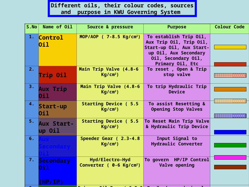
S.No Name of Oil Source & pressure Purpose Colour Code1. Control Oil MOP/AOP ( 7-8.5 Kg/cm2) To establish Trip Oil, Aux
Trip Oil, Trip Oil, Start-up Oil, Aux Start-up Oil, Aux Secondary Oil, Secondary
Oil, Primary Oil, Etc2.
Trip OilMain Trip Valve (4.8-6
Kg/cm2)To reset , Open & Trip
stop valve
3. Aux Trip Oil
Main Trip Valve (4.8-6 Kg/cm2)
To trip Hydraulic Trip Device
4. Start-up Oil
Starting Device ( 5.5 Kg/cm2)
To assist Resetting & Opening Stop Valves
5. Aux Start-up Oil
Starting Device ( 5.5 Kg/cm2)
To Reset Main Trip Valve & Hydraulic Trip Device
6. Aux Secondary Oil
Speeder Gear ( 2.3-4.8 Kg/cm2)
Input Signal to Hydraulic Converter
7. Secondary Oil (HP/IP)
Hyd/Electro-Hyd Converter ( 0-6 Kg/cm2)
To govern HP/IP Control Valve opening
8.Primary Oil
Primary Oil Pump ( 0-2.3 Kg/cm2)
Feedback speed signal for HG
9.Test Oil
Over Speed Test Device ( 2.0 Kg/cm2)
To test Over Speed Test Device
10. Drains
Different oils, their colour codes, sources and purpose in KWU Governing System

AOP
MOP
AOP Discharge header
Filtered Control Oil
Remote Trip Solenoid Valves
Main Trip Valves
Hyd. Trip Device
TEST V/V STOP V/VSERVO MOTOR
STOP & CONTROL VALVE
CONTROL VALVE SERVO MOTOR
Hyd
C
onverter
Electro-H
yd
Con
verter
Starting
Device
Secondary Oil
Tri
p O
il
Aux Start-up Oil
Start-up Oil
Au
x T
rip
O
il
Filtered Controlled Oil
Filter
BLOCK DIAGRAM OF GOVERNING SYSTEMBLOCK DIAGRAM OF GOVERNING SYSTEM

TO TEST V/V OF STOP V/V
TO MTV & HTD V/V
CONTROL OIL FROM AOP/MOP
STARTING DEVICE
STARTING DEVICE
BRINGING THE STARTING DEVICE TO “0” POSITION TO BUILD START-UP & AUX STATR-UP OIL TO RESET STOP&
MAIN TRIP VALVES AND HYD. TRIP DEVICE
Aux Start-up Oil (5.5 Kg/cm2)
Start-up Oil (5.5 Kg/cm2)
RAISING STARTING DEVICE POSITION TO DE-PRESSURISE START-UP & AUX STATR-UP OIL TO OPEN STOP VALVES AND PRODUCING AUX SECONDARY OIL
75 100
25
50
0
Starting Device
In %
Position at MCR
Drain
Drain
Hand Wheel
Motor
Start-up Oil (0 Kg/cm2)
Aux Start-up Oil (0 Kg/cm2)
STARTING DEVICE
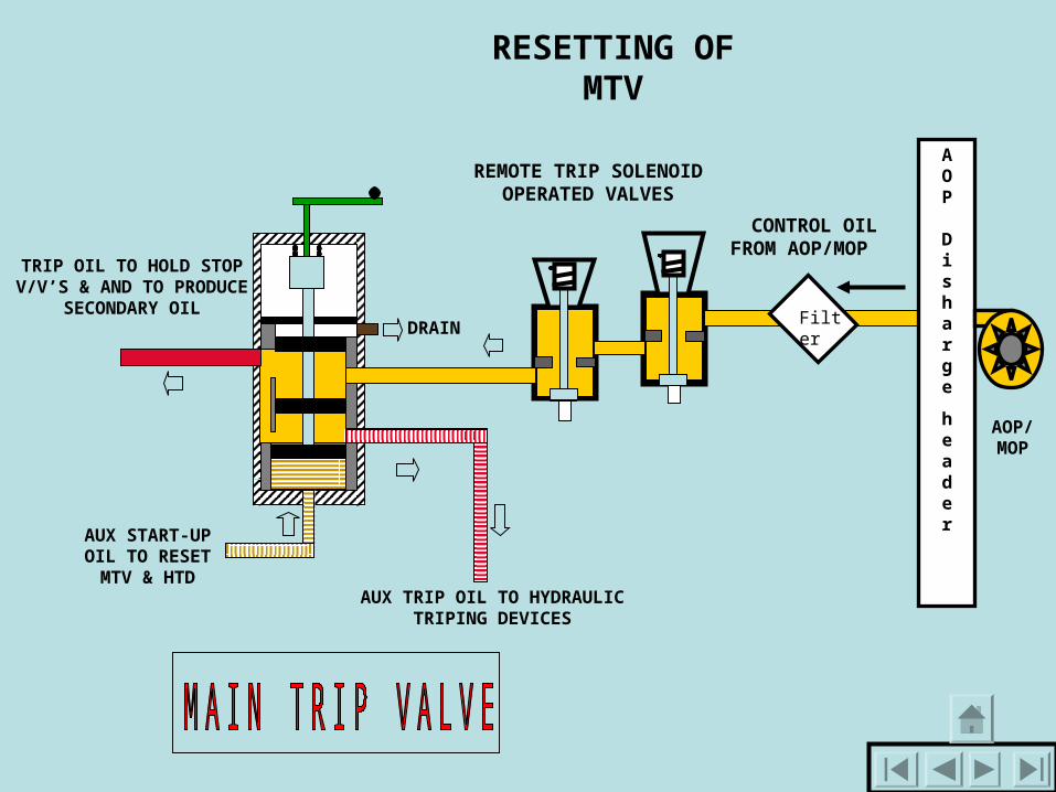
REMOTE TRIP SOLENOID OPERATED VALVES
TRIP OIL TO HOLD STOP V/V’S & AND TO
PRODUCE SECONDARY OIL
AUX TRIP OIL TO HYDRAULIC TRIPING
DEVICES
CONTROL OIL FROM AOP/MOP
AUX START-UP OIL TO
RESET MTV & HTD
FilterDRAIN
AOP Disharge
header
AOP/ MOP
RESETTING OF MTV

REMOTE TRIP SOLENOID OPERATED VALVES
TRIP OIL TO HOLD STOP V/V’S & AND TO
PRODUCE SECONDARY OIL
AUX TRIP OIL TO HYDRAULIC TRIPING
DEVICES
TRIPPING OF MTV THROUGH RTSV (ELECTRICAL)
CONTROL OIL FROM AOP/MOP
AUX START-UP OIL TO
RESET MTV
FilterDRAIN
TRIPPING THROUGH RTSV

AUX TRIP OIL TO THE HYDRAULIC TRIPING DEVICES
AUX START-UP OIL TO
RESET MTV
HYDRAULIC TRIP DEVICE
REMOTE TRIP SOLENOID OPERATED VALVES
TRIP OIL TO HOLD STOP V/V’S & AND TO
PRODUCE SECONDARY OIL
AUX TRIP OIL TO HYDRAULIC TRIPING
DEVICES
TRIPPING OF MTV THROUGH HYDRAULIC TRIP DEVICE
(MECHANICAL)
CONTROL OIL FROM AOP/MOP
FilterDRAIN
AUX START-UP OIL TO RESET HYD TRIP DEVICES
TRIPPING THROUGH HYD TRIPDEVICE

AUX TRIP OIL TO THE HYDRAULIC TRIPING DEVICES
AUX START-UP OIL TO
RESET MTV
HYDRAULIC TRIP DEVICE
REMOTE TRIP SOLENOID OPERATED VALVES
TRIP OIL TO HOLD STOP V/V’S & AND TO
PRODUCE SECONDARY OIL
AUX START-UP OIL TO RESET
HYDRAULIC TRIP DEVICES
RESETTING OF RTSV, HYD. TRIP DEVICES & MTV THROUGH
CONTROL OIL FROM AOP/MOP
FilterDRAIN
RESETTING OF RTSV, HYD. TRIP DEVICES & MTV THROUGH

RESETTING OF RTSV(DE-ENERGIZING)
& HYD. TRIP DEVICES & MTV THROUGH STARTING DEVICE AT “0”
POSITION
FilterDRAIN
STOP VALVE
OPENING OF STOP VALVES BY RAISING STARTING DEVICE
START-UP OIL TO TEST V/V
TRIP OIL TO STOP V/V
STOP VALVE SERVO-MOTOR
HYD TRIP DEVICE
DRAIN
AUX TRIP OIL TO HYD TRIP DEVICE
AUX TRIP OIL TO HYD TRIP DEVICE
AUX START-UP OIL TO HYD TRIP DEVICE
AU
X S
TA
RT
-UP
OIL
T
O M
TV
MTV
S/D
RTSV’S
TEST VALVE
STOP V/V OPERATION

STOP VALVE SERVO-MOTOR
SPRING
CYLINDER
SPRING DISC
PISTON
PISTON DISC
TRIP OIL ABOVE PISTON
TRIP OIL BELOW PISTON DISC
RESETTING OPENING
TRIPPING
Drain
RESETTING/OPENING/TRIPPING
OF STOP VALVE

TURBINE OVERSPEED TRIP DEVICE
FLY BOTL
Aux Trip Oil
AUX START-UP OIL TO RESET
AUX TRIP OIL
Drain
TURBINE OVERSPEED TRIP DEVICE

TURBINE SHAFT
AUX START-UP OIL TO RESET
AUX TRIP OIL
DrainTRIPPING OF Thrust Bearing TRIP DEVICE
RESETTING OF Thrust Bearing TRIP DEVICETEST
OIL
THRUST BEARING TRIP
DEVICE

Drain
Control Oil
Atmosphere
Vacuum
Aux Trip Oil
Drain
LOW VACUUM TRIP DEVICE
Resetting Of Low Vacuum Trip Device
Tripping Of Low Vacuum Trip Device
Low Vacuum Trip Device

HP Sec. Oil
IP Sec. Oil
Follow - up valves
Hydraulic ConverterAux Sec Oil
from S/G
Trip Oil From MTV
Trip Oil From MTV
Electro-Hydraulic Converter Follow - up valves
Amplifier Piston
Amplifier Piston
0-10V Supply from
ATRS
Control Oil
Control Oil
Trim Device
Trim Device
HP Sec. Oil
IP Sec. OilHG & EHG
HG/EHG

THANK YOU