government polytechnic, meham
TRANSCRIPT

GOVERNMENT POLYTECHNIC, MEHAM
Branch: Mechanical Engineering
Semester: 4th Sem.
Subject: Workshop Technology -II

CONTENTS:
1. Cutting tools
2. Various types of single point cutting tools and their uses
3. Single point cutting tool geometry
4. Tool signature and its effect
5. Heat produced during cutting and its effect
6. Cutting speed
7. Feed
8. Depth of cut
9. Properties of the cutting tool materials
10. Study of various cutting tool materials viz. High-speed
steel, tungsten carbide, cobalt steel cemented carbides, stellite,
ceramics and diamond.
1. CUTTING TOOLS
It may be define as the tools which are used for cutting the metals in desired shaped and
size.
Types of cutting tool:
Single point cutting tool: The cutting tool which is terminated in a single point is
known as the single point cutting tool. These are used in lathes, shapers, planers.
Multi point cutting tool: The cutting tool which is terminated more than one point as
known as the multi point cutting tool. These are used in milling cutter, drills,
broaches, etc.
2. VARIOUS TYPES OF SINGLE POINT CUTTING TOOL AND THEIR USES
Turning tool: The tools which are use for turning or for reducing the diameter of
the job. They are of two type:
i. Left hand turning tool
ii. Right hand turning tool

Facing tool: The tool which is used for facing or for reducing the length of the
job.
They are of two types:
i. Left hand facing tool
ii. Right hand facing tool
Chamfering tool: The tool which is used for the bevelling the corners of the
workpiece for small length.
They are of two types:
i. Left hand chamfering tool
ii. Right hand chamfering tool
External threading tool: This tool is used for cutting the external threads on the
workpiece as per required shape and size.

Internal threading tool: It is used for cutting the internal thread in the holes.
Boring tool: It is used to enlarge an already existing hole in the workpiece.
Some important terms related to single point cutting tool
1. Shank; It’s the main body of the tool and it is that part of the tool which is
gripped in the tool holder.
2. Face: It is the top surface of the tool between the shank and the cutting edge.
3. Flank: It is the portion of the tool which face the work or it is the surface below
and adjacent to the cutting edge.
4. Heel: It is the curved portion at the bottom of the tool where the base and flank of
the tool meets.
5. Base: It is the bearing surface of the tool in which it is held in the tool holder.
6. Nose: It is the point where side cutting edge and end cutting edge meet or
intersect.

7. Cutting edge: It is the edge on the face of the tool which removes material from
the workpiece.
3. SINGLE POINT CUTTING TOOL GEOMETRY
Back rack angle = 𝛾𝑦
Side rack angle = 𝛾𝑥
End relief/clearance angle = 𝛼𝑦 Side relief/clearance angle = 𝛼𝑥 End cutting edge angle = ∅𝑒 Side cutting edge angle = ∅𝑠 Nose radius = 𝛾
4. TOOL SIGNATURE AND ITS EFFECT
It is used to denote a standardised system of specifying the principle tool angle of a
single point cutting tool.
Effect of tool signature:
1. It reduced the cutting force required to shear the metal increase tool life and
reduce power consumption.
2. It improves the surface finish.
3. It allow the chips to flow in a convenient direction
5. HEAT PRODUCED DURING CUTTING AND ITS EFFECT

1. Due to friction: A lot of friction takes place between the tool and work piece and
the tool and the chips. The passing of the chips over the tool contributes the
maximum friction.
2. Due to plastic deformation of metal: Due to sufficiently high pressure exerted
by the tool on adjacent grain of the work piece.
3. Chips deformation: In machining operation, the chip curls out and tensile and
compressive stresses are generated on the chips. This result in distortion of grains
and consequent generation of heat.
5.1 Effect of heat produced during metal cutting:
It reduces the tool life.
It reduces the surface finish.
It causes the welding of chips with the face of tool.
Repeat replacement of tools occurs which increase the cost.
6. CUTTING SPEED
It may be define as the speed at which the cutting edge passes over the material.
7. FEED
The distance through which the tool advance into or along the workpiece each time the
tool passes a certain position in its travel over the surface.
8. DEPTH OF CUT
The perpendicular distance measured from the machined surface to the in cut surface of
the work piece.
9. PROPERTIES OF THE CUTTING TOOL MATERIALS
Tool material must be at least 30 to 50% harder than the work piece material.
Tool material must have high hot hardness temperature.
High toughness
High wear resistance
High thermal conductivity
Lower coefficient of friction
Easiness in fabrication and cheap
10. STUDY OF VARIOUS CUTTING TOOL MATERIALS
11.1 High speed steel (H.S.S)
General use of HSS is 18-4-1.
18- Tungsten is used to increase hot hardness and stability.
4 – Chromium is used to increase strength.
1- Vanadium is used to maintain keenness of cutting edge.
In addition to these 2.5% to 10% cobalt is used to increase red hot hardness.

Cemented carbides
Produced by powder metallurgy technique with sintering at 1000°C. Speed can be used 6 to 8 times that of H.S.S.
Can withstand up to 1000°C.
High compressive strength is more than tensile strength.
They are very stiff and their young’s modulus is about 3 times that of the steel.
High wear resistance.
High modulus of elasticity.
Low coefficient of thermal expansion.
High thermal conductivity, low specific heat, low thermal expansion.
According to ISO the various grades of carbide tool materials grouped as
1. For cutting CI and non-ferrous metals are designated as K10 to K50
2. For cutting steel are designated as p10 to p50
3. For general purpose application are designated as M10 to M50.
The advantages of carbide tools are
They have high productivity capacity.
They produce surface finish of high quality.
They can machine hardened steel.
Their use leads to reduction in machining costs.
Ceramics and sintered oxides
Ceramics and sintered oxides are basically made of Al2O3, These are made by
powder metallurgy technique.
Used for very high speed (500m/min).
Used for continuous cutting only.
Can withstand upto 1200°C.
Have very abrasion resistance.
Used for machining CI and plastics.
Has less tendency to weld metals during machining.
Generally used ceramic is sintered carbides.
Another ceramic tool material is silicon nitride which is mainly used for CI.
Cermets
Cermets is the combination of ceramics and metals and produced by Powder
Metallurgy process.
When they combine ceramics will give high refractoriness and metals will give
high toughness and thermal shock resistance.
For cutting tools usual combination as Al2O3 + W + Mo + boron + Ti etc.
Usual combination 90% ceramic, 10% metals.
Increase in % of metals reduces brittleness some extent and also reduces wear
resistance.
Diamond
Diamond has extreme hardness, low thermal expansion, high thermal
conductivity and very low coefficient of friction.
Cutting tool material made of diamond can withstand speeds ranging from 1500
to 2000m/min.

On ferrous metals diamond are not suitable because of the diffusion of carbon
atoms from diamond to work-piece.
Can withstand above 1500°C.
A synthetic (man-made) diamond with polycrystalline structure is recently
introduced and made by powder metallurgy process.

GOVERNMENT POLYTECHNIC, MEHAM
Branch: Mechanical Engineering
Semester: 4th Sem.
Subject: Workshop Technology -II
CONTENTS
11. Introduction
12. Function of cutting fluids
13. Properties of cutting fluids
14. Types of cutting fluids
15. The factor under consideration during selection of a
cutting fluid
16. Application of cutting fluids
17. Lubricant
18. Characteristics of good lubricant
19. Difference between cutting fluids and lubricants

CUTTING FLUIDS AND LUBRICANTS
INTRODUCTION:
Any substance applied to a tool during cutting operation release /decrease heat removal of
chips and increase tool life is known as cutting fluids.
The cutting fluids have little effect on cutting efficiency, when machine are made to
operate at high speed. Water based fluids are best suited for cooling action due to their high
specific heat and thermal conductivity. The rate of transfer of heat by water based fluid. The
cooling efficiency of any cutting fluids does not depend decided only by its thermal
conductivity other factor which considered are wetting action, cooling action and vapours
formation of fluids.
FUNCTION OF CUTTING FLUIDS-
1. To reduce the cutting force.
2. To decrease wear and tear of the tool, so it’s helpful to increase the tool life.
3. Cutting fluids provided lubricating effect to the tool.
4. To improve the surface finished and machinability of any machine.
5. Cutting fluids protect the finished surface from oxidation.
6. To wash away the chips and dust from working surface.
7. Cutting fluids minimize friction at the mating surface, so its prevent increase the
temperature.
PROPERTIES OF CUTTING FLUIDS
1. It should be chemically stable
2. It should be non-corrosive.
3. It should have high flash point.
4. No skin irritation.
5. Anti -welding properties.
6. Low evaporation rate.
7. Deteriorate on storage.

8. Low viscosity.
9. No de-colorization.
10. It should be cheap.
TYPES OF CUTTING FLUIDS
1. Neat cutting oils-
These oils are not mixed with water for cutting operations. These cutting oils are a mixture of
number of different types of mineral oils together these are used when cutting speed is slow
and lowest feed are used or with externally tough material. These cutting oils have good
cooling properties. The main disadvantage of neat cutting oils that they are responsible for
dirty work areas by shipping from the machine.
2. Soluble oils-
These are the compounds of mineral oils an emulsified base when mix with water emulsified
base cause, the formation of oils water emulsion/solution. Water has excellent cooling
properties and oils have good properties of lubrication and corrosion resistance. The amount
of water varies with the types of operation. This is used for drilling, milling, lathe etc.
3. Synthetic fluids-
These fluids contain no oils but are mixer of chemicals mix in water to give lubricating and
anti-corrosion properties. These are a clear transparent solution with water, during grinding
operation ratio up to 8O%. They are easily mix with water and do not produce smoke during
cutting.
4. Semi-synthetic fluids-
These are recently by develop cutting fluids, these fluids has a small amount of oils mix in
water as well as dissolved chemical. These cutting fluids are safer to use, do not produce
smoke and no slippery film on work piece.
5. Mineral cutting oils-
These are composed one or more mineral oils, fatty oils or fatty acids. These oils are used in
some light machining operation. The fatty oils both animals and vegetable are used in
combination with mineral oils. They are not chemically acting.
6. Chemical additive oils-
Sulphur and chlorine increase the lubricating and cooling properties of cutting oils. They also
provide anvil properties to the cutting oils.

7. Sulphurised mineral oils-
These oils minimized tearing and rough finish, they are commonly used for machining low
carbon steel, but highly sulphurised mineral oils are not used for copper and its alloys.
8. Chemical compounds -
These are the oils mixture of sodium nitrate with water. They are generally used for grinding
operation. The water provides good cooling properties where lubricating properties are not so
important during grinding.
THE FACTOR UNDER CONSIDERATION DURING SELECTION OF A CUTTING
FLUIDS-
1. The process of machining.
2. The cutting tool materials.
3. The material of a work piece.
4. Speed of cut /cutting speed of machine.
5. Cutting fluids also depend on speed as well as depth of cut.
6. Requirement of surface finished.
7. Human interaction.
8. Economically available on low price.
APPLICATION OF CUTTING FLUIDS-
The cutting fluids may be applied of the cutting tools in following ways:-
1. By hand or brush:-
In case of low production, the cutting fluids may be applied by hand or brush either to
material being cut or the cutting tool.
2. Flood method:-
For the effective use of cutting fluids and for heavy and continuous cutting, the fluids should
penetrate into the cutting zone. for this pump is used to supply the cutting fluid. Here a
continuous stream of cutting fluids is directed at the cutting zone with help of nozzle jet.

The used cutting fluids drop into the tank at the bottom. Before it is recirculated by the pump,
it passes through many filters to remove chips and dirt.
3. Jet Method:-
It is also known as high jet method under suitable circumstances. This method gives a
significant increase in tool life. In this system cutting fluids is pumped under a pressure of 30
to 40 kg/cm2 from the cutting fluids take in the base of the machine the high-5 speed jet
depended upon slight irregularities in both the cutting edge of the tool and work surface.

4. Mist method:-
In this system cutting fluids is vaporized over the work piece and cutting tool. Due to high
velocity fluids application. The surface area of cutting fluids is much more than fluids
method, jet method the process of producing mist of the cut fluid is based on the venturi
principle as shown in fig. The high pressured air flowing by a syphon tube, draw the fuel into
the nozzle.
LUBRICANT:-
A lubricant is the substance which reduce the force of friction between two relatively moving
solid surface in the constant with each other.
CHARACTERISTICS OF A GOOD LUBRICANT:-
1. High viscosity.
2. Viscosity index.
3. Flash and fire point is high.
4. Pour point is high.
5. Oiliness is high.
6. Acid value is low.
7. Emulsification is high.
DIFFERENCE BETWEEN CUTTING FLUID AND LUBRICANT


GOVERNMENT POLYTECHNIC, MEHAM
Branch: Mechanical Engineering
Semester: 4th Sem.
Subject: Workshop Technology-II

INTRODUCTION
Lathe is one of the oldest important machine tools in the metal working industry. A lathe operates on the principle of a rotating work piece and a fixed cutting tool.
A rope wound round the work with its own end attached to a flexible branch of tree and other end being pulled by man caused job to rotate intermittently. With its further development a strip of wood called “lath” was used to support the rope and that is how the machine came to be known as “lathe”.
The cutting tool is feed into the workpiece, which rotates about its own axis, causing the workpiece to be formed to the desired shape.

TYPES OF LATHE
• Engine Lathe
• Bench Lathe
• Tool room Lathe
• Automatic Lathe
• Turret Lathe

ENGINE LATHE
• This term ‘engine’ is associated with the lathe owing to the fact that early lathes were driven by steam engine. It is also called centre lathe. The most common form of lathe, motor driven and comes in large variety of sizes and shapes.

Continue..
Engine lathes are classified according to the various
designs of headstock and methods of transmitting power to
the machine.
1. Belt Driven Lathe
2. Motor Driven Lathe
3. Gear Head Lathe
The power to the engine lathe spindle may be given with
the help of a belt drive from an overhead line shaft but
most modern machines have a captive motor with either
a cone pulley driven or an geared headstock
arrangement.

BENCH LATHE • A bench top model usually of low power used to make precision
machine small work pieces.
• It is used for small w/p having a maximum swing of 250 mm at the face plate. Practically it consists of all the parts of engine lathe or speed lathe.

a
d
or
es,
TOOL ROOM LATHE
A tool room lathe having
features similar to an engine
lathe is much more accurately
built and has a wide range of
spindle speeds ranging from
very low to a quite high spee
up to 2500 rpm.
This lathe is mainly used f
precision work on a tools, di
gauges, and in machining
work where accuracy is
needed.

AUTOMATIC LATHE
• A lathe in which the work piece is automatically fed and removed without use of an operator. It requires very less attention after the setup has been made and the machine loaded.

Continue..
Once tools are set and the machine is started it performs automatically all the operations to finish the job.
After the job is complete, the machine will continue to repeat the cycles producing identical parts.
An operator can maintain five or six such a types of lathes at a time simply look after the general maintenance of the machine and cutting tools.

TURRET LATHE • Turret lathe is the adaptation of the engine lathe where the
tail stock is replaced by a turret slide(cylindrical or
hexagonal). Tool post of the engine lathe is replaced by a
square cross slide which can hold four tools.

Continue..
It has heavier construction and provides wider range of speeds.
The saddle carrying the turret head moves along the whole length of the bed. Much longer jobs can be machined.
Turret head directly mounted on the saddle. The front tool post can carry 4 tools and rear tool post may have 1 or 2 tools. Turret may have4 to 6 tools.
More than one tool may be set to operate simultaneously. There is no lead screw.

Lathe Machine

Parts of Lathe Machine

Lathe Bed
• This is heavy rugged casting
made to support the working
parts of lathe and also guide
and align major parts of
lathe.
• Made to support working
parts of lathe.
• On top section are machined
ways.
• Guide and align major parts
of lathe.

Head Stock
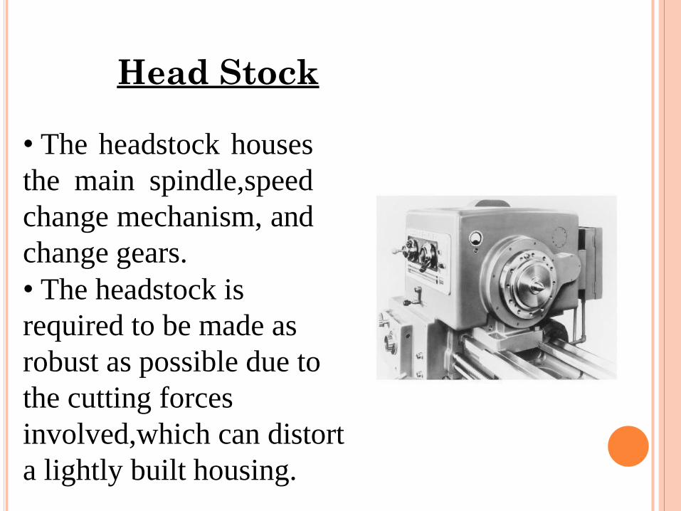
• The headstock houses
the main spindle,speed
change mechanism, and
change gears.
• The headstock is
required to be made as
robust as possible due to
the cutting forces
involved,which can distort
a lightly built housing.

Head Stock
• Induce harmonic
vibrations that will
transfer through the
work piece, reducing the
quality of the finished
work piece.

QUICK CHANGE GEAR BOX • Contains number of different-size gears.
• Provides feed rod and lead-screw with various speeds for turning and thread-cutting operations
TOP VIEW

Continue..
The arrangement which are employed in feed gear
boxes to obtain multispindle speeds and different
rates of feeds are:
I. Sliding Gear Mechanism
II. Sliding Clutch Mechanism
III. Gear Cone And Tumbler Gear Mechanism
IV. Sliding Key Mechanism
V. Combination of any two or more of the above
• Usually two or three levers must be moved to
obtain the desired combination within a given
range.

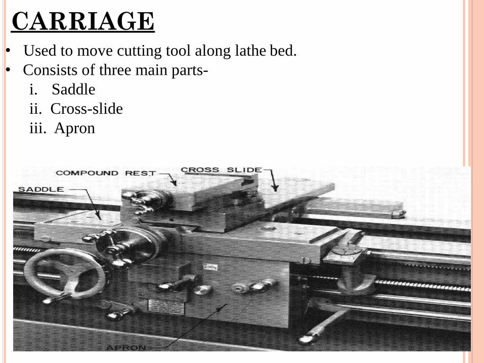
CARRIAGE • Used to move cutting tool along lathe bed.
• Consists of three main parts-
i. Saddle
ii. Cross-slide
iii. Apron

Continue..
Movement of entire carriage assembly along the bed provides feed for the tool parallel to the lathe axis.
The compound rest can be swivelled on the cross slide in the horizontal plane about vertical axis.
To the front of the carriage is attached the apron. It is fastened to the saddle and hangs over the front of the bed.
The apron houses the automatic feed mechanism for longitudinal and cross feeds and the split nut for thread cutting.

CROSS SLIDE
• Mounted on top of saddle. • Provides manual or automatic cross movement for cutting tool.

APRON
• Fastened to saddle.
• Houses gears and
mechanism required to
move carriage or cross-
slide automatically.
• Locking-off lever inside
apron prevents engaging
split-nut lever and
automatic feed lever at
same time.
• Apron hand wheel
turned manually to move
carriage along lathe bed

TAILSTOCK Upper and lower tailstock castings.
• Adjusted for taper or parallel turning by two screws set in base.
• Tailstock clamp locks tailstock in any position along bed of lathe.
• Tailstock spindle has internal taper to receive dead center.
• Provides support for right-hand end of work.

Continue..
In tail stock jobs of different lengths are provided
with quill which can be moved in and out by
means of a screw and then locked in position.
The movement of the quill is parallel to the lathe
axis.
The quill has a tapered bore into which is fitted a
hardened centre which locates and holds the w/p
when turning between centre.
This bore may also be used for supporting tools for
operations like drilling and reaming.

AUTOMATIC FEED LEVER
• Engages clutch that provides automatic feed to
carriage.
• Feed-change lever can be set for longitudinal
feed or for cross-feed.
• In neutral position, permits split-nut lever to
be engaged for thread cutting.
• Carriage moved automatically when split-nut
lever engaged

FEED OF AN ENGINE LATHE
• Distance carriage will travel in one revolution of
spindle.
• Depends on speed of feed rod or lead screw.
• Controlled by change gears in quick-change
gearbox.
• Obtains drive from headstock spindle through end
gear train.
• Chart mounted on front of quick-change gearbox
indicates various feeds.

Cutting Tool

Work Holding Devices
(a) and (b) Schematic illustrations of a draw-in-type collets. (c) A push-out type collet. (d) Workholding of a part on a face plate.

Types Of Chuck
- Forholding
cylindrical stock
centered.
- For facing/center
drilling etc.
- This is independent chuck generally has four jaws , which are adjusted individually on the chuck face by means of adjusting screws.

-Thin jobs
can be held
by means of
magnetic
chucks.
-Collet chuck
is used to
hold small
work pieces.

SAFTY PRECAUTIONS
Don’t touch cutter or chips while machine is running.
Make sure work is clamped tightly in chuck or collet.
Be careful to stay clear of chuck jaws.

Continue..
All lathe operators must be constantly aware of the safety.
Handle sharp cutters, centres, and drills with care.
Remove chuck keys and wrenches before operating.
Always wear protective eye protection.
Always stop the lathe before making adjustments.
Know where the emergency stop is before operating the
lathe.
Correct dress is important, remove rings and watches.
Do not change spindle speeds until the lathe comes to a
complete stop.

GOVERNMENT POLYTECHNIC, MEHAM
Branch: Mechanical Engineering
Semester: 4th Sem.
Subject: Workshop Technology-II
Chapter 2: Drilling

DRILLING
Drilling is the operation of producing circular hole in the work-piece by using a rotating cutter called DRILL.
The machine used for drilling is called drilling
machine.
The drilling operation can also be accomplished in
lathe, in which the drill is held in tailstock and the work is held by the chuck.
The most common drill used is the twist drill.

DRILLING MACHINE
• It is the simplest and accurate machine used in production shop.
• The work piece is held stationary ie. Clamped in position and the drill rotates to make a hole.
• Types :-
a) Based on construction:
Portable, Sensitive,Radial, up-right, Gang, Multi-spindle
b) Based on Feed:
Hand and Power driven

SENSITIVE DRILLING MACHINE
Drill holes from to 15mm
Operator senses
the cutting action so sensitive drilling machine

UP-RIGHT DRILLING MACHINE
• Drill holes upto 50mm
• Table can
move vertically and radially

RADIAL DRILLING MACHINE
It the largest and most versatile used fro drilling medium to large and heavy work pieces.

DRILL MATERIALS The two most common types are
1. HSS drill
- Low cost
2. Carbide- tipped drills
- high production and in CNC machines
Other types are
Solid Carbide drill, TiN coated drills, carbide coated masonry
drills, parabolic drills, split point drill

Drilling And Drills
Types of drills
– Twist drill: most common drill
– Step drill: produces holes of two or more different diameters
– Core drill: used to make an existing hole bigger

DRILL FIXED TO THE SPINDLE
Drilling operations
Drilling Centre Hole
Drilling Deep Holes
Drilling Thin
Material
Drilling Pilot Hole

TOOL NOMENCLATURE

TOOL HOLDING DEVICES
The different methods used for holding drill in a
drill spindle are
By directly fitting in the spindle
hole.
By using drill sleeve
By using drill socket
By using drill chuck

WORK HOLDING DEVICES

DRILLING OPERATIONS…
Operations that can be performed in a drillin g machine are
Drilling
Reaming
Boring
Counter boring
Countersinking
Tapping

OPERATIONS IN DRILLING MACHINE

TYPES OF CUTTERS
Reamers :-
Multi tooth cutting tool
Accurate way of sizing and finishing the pre-existing hole.
Accuracy of 0.005mm can be achieved
Boring Tool:-
Single point cutting tool.
Boring tool is held in the boring bar which has the shank.
Accuracy of 0.005mm can be achieved.

TYPES OF CUTTERS
Countersinks :-
Special angled cone shaped enlargement at the end of the
hole
Cutting edges at the end of conical surface.
Cone angles of 60°, 82°, 90°, 100°, 110°, 120°
Counter Bore Tool:-
Special cutters uses a pilot to guide the cutting action .
Accommodates the heads of bolts.

COUNTER BORE AND SPOT FACING

TYPES OF CUTTERS
Combined Countersinks and central drill :-
Special drilling tool to start the hole accurately.
At the end it makes countersinks in the work piece.
Gun drill :-
Machining of lengthy holes with less feed rates.
To overcome the heating and short life of the normal drill to l
o

TYPES OF CUTTERS
Tapping:-
For cutting internal
thread
Multi cutting edge tool.
Tapping is performed
either by hand or by
machine.
Minor dia of the thread
is drilled and then
tapping is done.

WORK HOLDING DEVICES
1. Machine Table
Vice

WORK HOLDING DEVICES
Step Blocks
Clamps
V-Blocks
Angles
Jigs
T- Slots Bolt

DEFINITIONS
Cutting Speed (v):-
It’s the peripheral speed of the drill
v = *D*N where
D = dia of the drill in m
N = Speed of rotation in rpm
Feed Rate (f):- It’s the movement of drill along the axis (rpm)
Depth of Cut (d):- The distance from the machined surface to the drill axis
d = D / 2

Material Removal Rate:- It’s the volume of material removed by the drill per unit time
MRR = ( D2 / 4) * f * N mm3 / min
Machining Time (T) :- It depends upon the length (l) of the hole to be drilled , to the
Speed (N) and feed (f) of the drill
t = L / f N min

PRECAUTIONS FOR DRILLING MACHINE
Lubrication is important to remove heat and friction.
Machines should be cleaned after use
Chips should be removed using brush.
T-slots, grooves, spindles sleeves, belts, pulley should be cleaned.
Machines should be lightly oiled to prevent from rusting

SAFETY PRECAUTIONS
Do not support the work piece by hand – use work holding device.
Use brush to clean the chip
No adjustments while the machine is operating
Ensure for the cutting tools running straight before starting the operation.
Never place tools on the drilling table
Avoid loose clothing and protect the eyes.
Ease the feed if drill breaks inside the work piece.

GOVERNMENT POLYTECHNIC, MEHAM
Branch: Mechanical Engineering
Semester: 4th Sem.
Subject: Workshop Technology-II
Chapter 3: Lathe

INTRODUCTION
Lathe is one of the oldest important machine tools in the metal working industry. A lathe operates on the principle of a rotating work piece and a fixed cutting tool.
A rope wound round the work with its own end attached to a flexible branch of tree and other end being pulled by man caused job to rotate intermittently. With its further development a strip of wood called “lath” was used to support the rope and that is how the machine came to be known as “lathe”.
The cutting tool is feed into the workpiece, which rotates about its own axis, causing the workpiece to be formed to the desired shape.

TYPES OF LATHE
• Engine Lathe
• Bench Lathe
• Tool room Lathe
• Automatic Lathe
• Turret Lathe

ENGINE LATHE
• This term ‘engine’ is associated with the lathe owing to the fact that early lathes were driven by steam engine. It is also called centre lathe. The most common form of lathe, motor driven and comes in large variety of sizes and shapes.

Continue..
Engine lathes are classified according to the various
designs of headstock and methods of transmitting power to
the machine.
1. Belt Driven Lathe
2. Motor Driven Lathe
3. Gear Head Lathe
The power to the engine lathe spindle may be given with
the help of a belt drive from an overhead line shaft but
most modern machines have a captive motor with either
a cone pulley driven or an geared headstock
arrangement.

BENCH LATHE • A bench top model usually of low power used to make precision
machine small work pieces.
• It is used for small w/p having a maximum swing of 250 mm at the face plate. Practically it consists of all the parts of engine lathe or speed lathe.

a
d
or
es,
TOOL ROOM LATHE
A tool room lathe having
features similar to an engine
lathe is much more accurately
built and has a wide range of
spindle speeds ranging from
very low to a quite high spee
up to 2500 rpm.
This lathe is mainly used f
precision work on a tools, di
gauges, and in machining
work where accuracy is
needed.

AUTOMATIC LATHE
• A lathe in which the work piece is automatically fed and removed without use of an operator. It requires very less attention after the setup has been made and the machine loaded.
Continue..
Once tools are set and the machine is started it performs automatically all the operations to finish the job.
After the job is complete, the machine will continue to repeat the cycles producing identical parts.
An operator can maintain five or six such a types of lathes at a time simply look after the general maintenance of the machine and cutting tools.

TURRET LATHE • Turret lathe is the adaptation of the engine lathe where the
tail stock is replaced by a turret slide(cylindrical or
hexagonal). Tool post of the engine lathe is replaced by a
square cross slide which can hold four tools.

Continue..
It has heavier construction and provides wider range of speeds.
The saddle carrying the turret head moves along the whole length of the bed. Much longer jobs can be machined.
Turret head directly mounted on the saddle. The front tool post can carry 4 tools and rear tool post may have 1 or 2 tools. Turret may have4 to 6 tools.
More than one tool may be set to operate simultaneously. There is no lead screw.

Lathe Machine

Parts of Lathe Machine

Lathe Bed
• This is heavy rugged casting
made to support the working
parts of lathe and also guide
and align major parts of
lathe.
• Made to support working
parts of lathe.
• On top section are machined
ways.
• Guide and align major parts
of lathe.
Head Stock
• The headstock houses
the main spindle,speed
change mechanism, and
change gears.
• The headstock is
required to be made as
robust as possible due to
the cutting forces
involved,which can distort
a lightly built housing.

Head Stock
• Induce harmonic
vibrations that will
transfer through the
work piece, reducing the
quality of the finished
work piece.

QUICK CHANGE GEAR BOX • Contains number of different-size gears.
• Provides feed rod and lead-screw with various speeds for turning and thread-cutting operations
TOP VIEW

Continue..
The arrangement which are employed in feed gear
boxes to obtain multispindle speeds and different
rates of feeds are:
I. Sliding Gear Mechanism
II. Sliding Clutch Mechanism
III. Gear Cone And Tumbler Gear Mechanism
IV. Sliding Key Mechanism
V. Combination of any two or more of the above
• Usually two or three levers must be moved to
obtain the desired combination within a given
range.
CARRIAGE • Used to move cutting tool along lathe bed.
• Consists of three main parts-
i. Saddle
ii. Cross-slide
iii. Apron

Continue..
Movement of entire carriage assembly along the bed provides feed for the tool parallel to the lathe axis.
The compound rest can be swivelled on the cross slide in the horizontal plane about vertical axis.
To the front of the carriage is attached the apron. It is fastened to the saddle and hangs over the front of the bed.
The apron houses the automatic feed mechanism for longitudinal and cross feeds and the split nut for thread cutting.

CROSS SLIDE
• Mounted on top of saddle. • Provides manual or automatic cross movement for cutting tool.

APRON
• Fastened to saddle.
• Houses gears and
mechanism required to
move carriage or cross-
slide automatically.
• Locking-off lever inside
apron prevents engaging
split-nut lever and
automatic feed lever at
same time.
• Apron hand wheel
turned manually to move
carriage along lathe bed

TAILSTOCK Upper and lower tailstock castings.
• Adjusted for taper or parallel turning by two screws set in base.
• Tailstock clamp locks tailstock in any position along bed of lathe.
• Tailstock spindle has internal taper to receive dead center.
• Provides support for right-hand end of work.

Continue..
In tail stock jobs of different lengths are provided
with quill which can be moved in and out by
means of a screw and then locked in position.
The movement of the quill is parallel to the lathe
axis.
The quill has a tapered bore into which is fitted a
hardened centre which locates and holds the w/p
when turning between centre.
This bore may also be used for supporting tools for
operations like drilling and reaming.

AUTOMATIC FEED LEVER
• Engages clutch that provides automatic feed to
carriage.
• Feed-change lever can be set for longitudinal
feed or for cross-feed.
• In neutral position, permits split-nut lever to
be engaged for thread cutting.
• Carriage moved automatically when split-nut
lever engaged

FEED OF AN ENGINE LATHE
• Distance carriage will travel in one revolution of
spindle.
• Depends on speed of feed rod or lead screw.
• Controlled by change gears in quick-change
gearbox.
• Obtains drive from headstock spindle through end
gear train.
• Chart mounted on front of quick-change gearbox
indicates various feeds.

Cutting Tool

Work Holding Devices
(a) and (b) Schematic illustrations of a draw-in-type collets. (c) A push-out type collet. (d) Workholding of a part on a face plate.

Types Of Chuck
- Forholding
cylindrical stock
centered.
- For facing/center
drilling etc.
- This is independent chuck generally has four jaws , which are adjusted individually on the chuck face by means of adjusting screws.

-Thin jobs
can be held
by means of
magnetic
chucks.
-Collet chuck
is used to
hold small
work pieces.

SAFTY PRECAUTIONS
Don’t touch cutter or chips while machine is running.
Make sure work is clamped tightly in chuck or collet.
Be careful to stay clear of chuck jaws.

Continue..
All lathe operators must be constantly aware of the safety.
Handle sharp cutters, centres, and drills with care.
Remove chuck keys and wrenches before operating.
Always wear protective eye protection.
Always stop the lathe before making adjustments.
Know where the emergency stop is before operating the
lathe.
Correct dress is important, remove rings and watches.
Do not change spindle speeds until the lathe comes to a
complete stop.

GOVERNMENT POLYTECHNIC, MEHAM
Branch: Mechanical Engineering
Semester: 4th Sem.
Subject: Workshop Technology-II
Chapter 7: Jigs and Fixtures

Jigs & fixtures.
Jig vs fixture.
Principle of location.
Locating devices.
Clamping devices.
Types of jigs
Advantages of jigs & fixtures.
CONTENTS

It my be defined as a device which hold
and position the work piece & locates
or guide the cutting tool relative to
the work piece and usually is not fixed
to the machine table.
JIG

It my be defined as a work holding
device which hold and position the
work piece but does not locates or
guide the cutting tool. A fixture is
bolted or clamped to the machine
table.
FIXTURE

Hold the work piece & guide the cutting tool.
Lighter in construction.
Not fixed on machine table.
Perform drilling, reaming, tapping & counter boring operations.
Only holds & position the work piece but does not guide the cutting tool.
Heavier in construction.
Fixed on machine table.
Used for milling, grinding,shaping, turning, planning & welding operations.
JIG & FIXTURE

Locating element.
Clamping element.
A rigid body.
Tool guiding element.
Element for positioning or fastening of jig or
fixture on machine table.
ELEMENTS OF JIG &
FIXTURE

Rigidity
Location
Clamping
Loading
Ejecting
Design for safety
Collent passage
Swarf Clarence
PRINCIPLES OF JIG &
FIXTURE DESIGN

Process of positioning the work piece
relative to the work holder, and the work
holder relative to the cutting tool is
called locating.
LOCATION

A work piece free in space can move in an infinite number of directions.
This motion can be broken down into twelve directional movements, or "degrees of freedom."
All twelve degrees of freedom must be restricted to ensure proper referencing of a work piece.
THE MECHANICS OF
LOCATING

TWELVE DEGREE OF
FREEDOM
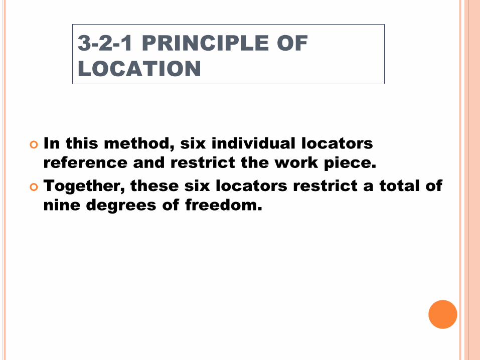
In this method, six individual locators
reference and restrict the work piece.
Together, these six locators restrict a total of
nine degrees of freedom.
3-2-1 PRINCIPLE OF
LOCATION

Three locators, or supports, are
placed under the work piece.
The next two locators are normally
placed on the secondary locating
surface.
The final locator is positioned at the
end of the part.
3-2-1 PRINCIPLE OF
LOCATION

3-2-1 PRINCIPLE OF
LOCATION

3-2-1 PRINCIPLE OF
LOCATION

3-2-1 PRINCIPLE OF
LOCATION

There are three general forms of location:
Plane.
Concentric.
Radial.
FORMS OF LOCATION

Plane-locating devices locate a part by its
external surfaces.
Concentric locators, locate a work piece from
a central axis.
Radial locators restrict the movement of a
work piece around a concentric locator.
FORMS OF LOCATION

SOLID LOCATOR

ADJUSTABLE LOCATOR

EQUALISING LOCATOR

The clamping forces should hold the workpiece in its located position.
should not cause any positional displacement or excessive distortion under the action of the clamping forces.
Clamping forces should be directed towards supporting and locating elements.
The force should be transmitted to the rigid sections of the body frame of the fixture.
PRINCIPLE OF
CLAMPING DEVICES

Screw clamp
Flat clamp
Pivoted clamp
Equalizing clamp
Latch clamp
Double acting clamp
Wedge clamp
Cam clamp
TYPES OF CLAMPS

The flat clamp supports the work by the
clamp face, which is pressed against the
work by tightening the nut. There are
several types of flat clamp.
Pivoted clamp
Equalizing clamp
Latch clamp
Double acting clamp
Cam clamps
FLAT CLAMP

The work can be gripped quickly by
tightening the screw, which actuates a
pivoted clamp on the face of the work.
The springs illustrated in figure guide the clamp of the same type in a horizontal position when the work is unloaded.
PIVOTED CLAMP

SOLID CLAMP

CLAMP WITH HEEL

The equalizing clamp, is
employed to exert equal
pressure on the two faces
of the work by the two legs
of the clamp pressed
against the work by the
same amount exacting
equal pressure on its two
clamping surfaces.
EQUALIZING CLAMP

Increased productivity.
Reduced led time.
Greater machining accuracy
Loading , unloading & handling time of
component is less.
Semi skilled lbour can be employed.
Less expenditure on quality control.
ADVANTGES OF JIG &
FIXTURES

Widens the technological capacity of
machine.
Reduction in manual handling
operations.
Enables easy machining of complex &
heavy components as such parts can
be rigidly held in proper location in jig
& fixtures.
Machine tool is fully or partially
automated.