ground improvement - purdue engineering · ground improvement – a discussion on dynamic...
TRANSCRIPT

Ground Improvement –
A Discussion on Dynamic Compaction
Chris Woods, P.E., D.GE., LEEDAP
BD+C
Vice-President

Presentation Outline
• Provide a basic understanding of the principles involved in
the design and implementation of a dynamic compaction
program.
• Discuss construction-phase issues that can arise.
• Illustrate some case histories and highlight the various soil
types that are conducive to improvement by dynamic
compaction.

Dynamic Compaction
The Pounder
The Crane
Some Dudes
Watching the
Weight Drop
The Operator
Typical Dynamic Compaction
Program • Consists of the repeated dropping of a 5 to 20 ton weight from
heights varying from 60 to 100 feet on a grid pattern.
• Most applicable to granular fill materials and sandy deposits.
• Depth of improvement is generally limited to about 25 to 30
feet or less.
• Shallow groundwater table not ideal for schedule, as energy is
lost at the soil/water interface and pore pressures build up,
requiring more time to complete the program.
• Generates very high vibration levels, not ideal for sites in
close proximity to sensitive existing structures (less than 50
feet or so).

Advantages to DC
• Allows conventional spread footing foundations
• Replaces expensive deep pile foundations
• Helps mitigate deep foundation costs in liquefiable areas
• Highly cost-effective when compared to other forms of ground improvement.
• Reduces settlement
• Increases bearing capacity
• Eliminates risk of hazardous waste exposure resulting from conventional undercut and replace (stays buried)
• Self-compensating – Softer areas are immediately apparent: and additional energy can be applied

Soils Conducive to Dynamic
Compaction Improvement
• Loose Sands
• Uncontrolled Fills
• Debris Fills
• Mine Spoils
• Sanitary Landfills
• Old Sand / Clay Pits
• Boulder Fills
• Liquefiable Soils
• Sinkhole / Mines
• Collapsible Soils
• Landfill Liner Preparation

Important Geotechnical Design
Parameters

Depth of Improvement

The Dynamic
Compaction
Principal

Governing Design Formulas
Depth of Influence:
𝐷 = 𝑛 ∗ 𝑊 ∗ 𝐻
n - an empirical value based on soil type and varies
from 0.35 to 0.6
W - weight in Mg
H - drop height in meters

Governing Design Formulas
Applied Energy (AE):
𝐴𝐸 = (𝑁 ∗ 𝑊 ∗ 𝐻 ∗ 𝑃)/ 𝑔𝑟𝑖𝑑 𝑠𝑝𝑎𝑐𝑖𝑛𝑔 2
N is the number of drops
W is the weight in Mg
H is the drop height in meters
P is the number of passes
Note: What’s not in here is the contact pressure of the
tamper.

Recommended Applied Energy
Recommended Energy Levels based on soil type are as
follows:
Pervious Coarse-Grained Soils (Zone 1) – 200 to 250 kJ/m3
Semi-Pervious Soils (Zone 2 and 3) – 250 to 350 kJ/m3
Landfill Material – 600 to 1,100 kJ/m3

Pounder Contact Pressure
• Although not accounted for in design formulas,
contact pressure of the pounder is a vital
component to successful program.
• Example:
– 16-ton weight, 7-foot round, 889 psf contact pressure.
– 15.3-ton weight, 5-foot octagon, 1,417 psf contact
pressure
• Higher pressure better for punching; lower
pressure better for uniformly lowering a site.

Design Considerations
• Historic Site Usage
• Subsurface Conditions
• Settlement – Long term and short term
• Schedule
Design Considerations
• Historic site usage – Understanding the prior use of a site can easily rule
out the use of a specific type of ground improvement.
– Specifically, old foundations, structural elements, etc.
can prohibit the ability to fully implement the
recommended program.
– Environmental concerns can also be of significance
when it comes to on-site soil handling concerns.

Design Considerations
• Subsurface Conditions – Highly plastic soils likely not the best application for
DC.
– Shallow groundwater may require more phases to the
program to allow for dissipation of pore pressures.
– Variable fill materials may require granular material to
stabilize.

Design Considerations
• Settlement – Granular soils will generally demonstrate post-
construction settlement during building construction.
– Perhaps most importantly, it should be understood
that ground improvement generally does not eliminate
settlement. It minimizes it to tolerable levels. The
anticipated settlements need to be discussed early
between the geotechnical and structural engineers
and accounted for in the design.
Design Considerations
• Schedule – Dynamic compaction can generally be implemented
at a pace of 5,000 to 10,000 square feet per day, per
rig, making it a relatively schedule-friendly form of
ground improvement.
– Winter weather can impact the schedule in the same
way that it can a traditional earthwork program.
– Tighter sites require more surgical approach, meaning
a longer schedule.

Real-Time Quality Control
• On-site inspection
• Crater depths (mapping)
• Surface elevation monitoring (settlement vs. heave)
• Decrease in depth of weight penetration with
successive drops
• Pore pressures

Dynamic
Compaction Drop
Plan
Post-Improvement
Acceptance Testing
• Large-Scale Load Test (where CPT & SPT are
unreliable i.e. construction rubble and cobbles)
• Standard Penetration Test (SPT)
• Cone Penetrometer Test (CPT)
• Pressuremeter Test (PMT)
• Dilatometer Test (DMT)
• Shear-Wave Velocity Profiling
KEY IS TIME!!

Vibrations

Dynamic Compaction Vibrations

Dynamic Compaction Vibrations 16-ton Weight Attenuation Curve
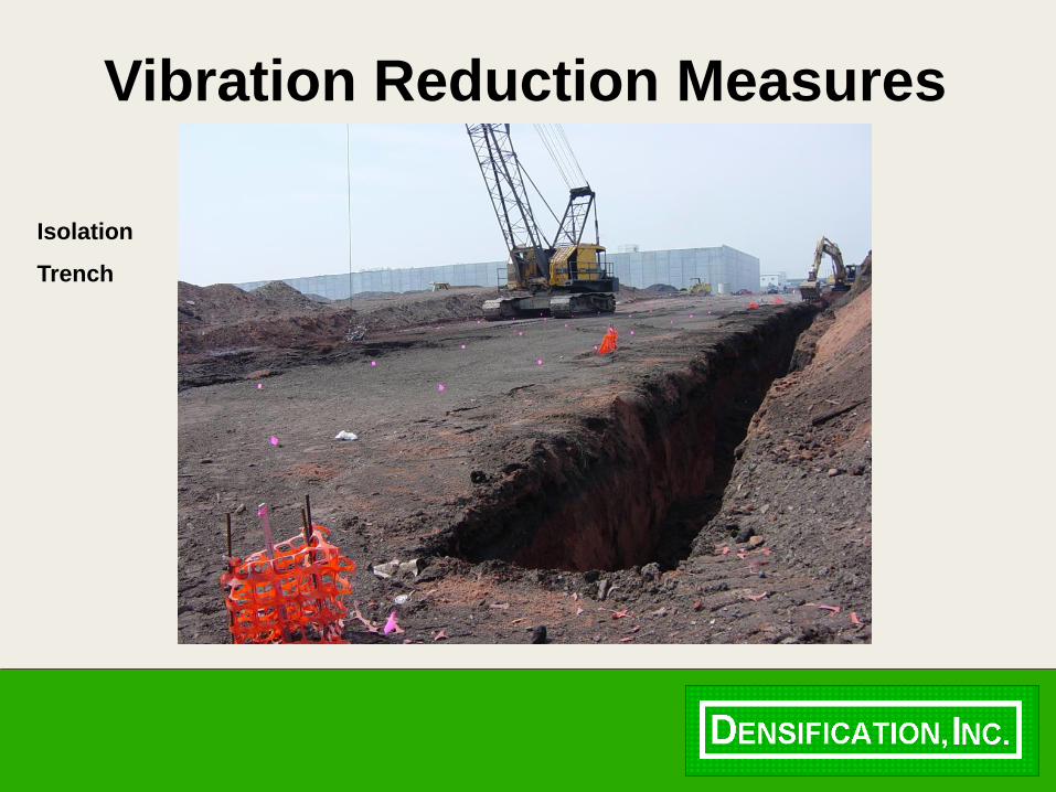
Vibration Reduction Measures
Isolation
Trench

Vibration Reduction Effectiveness

Project Examples

King of Prussia, PA
Searching for Karst
Sinkholes

Springdale, AR
Landfill
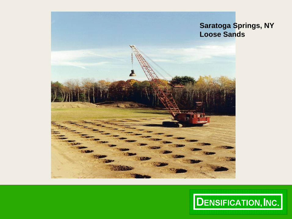
Saratoga Springs, NY
Loose Sands

Jersey City, NJ
Fill Site

JFK Airport,
Queens, NY
Liquefiable Sands

Fort Lewis, WA
Fluvial Outwash

Lake Shore Drive
Chicago, IL
Ash Fill from Coal
Tunnels beneath the
City

Miscellaneous Fill,
Shenyang, China

Yoloten, Mary, Turkmenistan
Leveled Dune Sands

Prudential Center
Newark, NJ
Fill Material

Job Where
Geotechnical
Field Engineer
Gave our
Operator a
Hard Time


Questions??
Contact Information:
Chris Woods, P.E., D.GE., LEED AP BD+C
Vice-President
Densification, Inc.
40650 Hurley Lane
Paeonian Springs, Virginia 20129
Email: [email protected]
www.densification.com