gse model 675 - meridian scale · gse model 675 precision counting s ... preset printouts ... a...
TRANSCRIPT

GSE Model 675 PRECISION COUNTING SCALE
Technical Reference Manual Version 1.0


Model 675
Technical Reference Manual Version 1.0

GSE 675 Precision Parts Counter Operation Manual Copyright © 2000 GSE Scale Systems. All rights reserved. Published by: GSE Scale Systems 42860 Nine Mile Road Novi, MI 48375 USA Information in this Operation Manual is subject to change without notice due to correction or enhancement. The information described in this manual is solely the property of GSE. No part of this manual may be reproduced or transmitted in any form or by any means, electronic or mechanical, including photocopying and recording and sold for any monetary figure without the express written permission of GSE.
GSE Locations
GSE Scale Systems 42860 Nine Mile Road Novi, MI 48375 U.S.A. Phone: (800) 755-7875 www.gse-inc.com
GSE Canada, Inc. 617 East Lake Road Airdrie, Alberta Canada T4B 2B8 Phone:(403) 948-9921 Fax: (403) 948-1449

ii
TABLE OF CONTENTS
CHAPTER 1: INTRODUCTION................................................................................... 1 STANDARD FEATURES...................................................................................................... 1 SPECIFICATIONS............................................................................................................... 2 ENCLOSURE ..................................................................................................................... 3 LOAD CELL ...................................................................................................................... 3
Load Cell Connections................................................................................................ 4 DISPLAY........................................................................................................................... 4 KEYPAD ........................................................................................................................... 5
Functions..................................................................................................................... 5 REAR PANEL .................................................................................................................... 6 BACK PANEL CONNECTIONS ............................................................................................ 7
CHAPTER 2: OPTION INSTALLATION .................................................................... 8 RECHARGEABLE BATTERY OPTION INSTALLATION.......................................................... 8
Installation instructions .............................................................................................. 9 Battery Status Icons .................................................................................................. 10
NON-RECHARGEABLE BATTERY OPTION INSTALLATION............................................... 11 Installation instructions ............................................................................................ 11 Installation instructions ............................................................................................ 13
THIRD SCALE OPTION .................................................................................................... 13 Installation instructions ............................................................................................ 14
FOURTH SCALE OPTION ................................................................................................. 15 Installation instructions ............................................................................................ 15
RS- 485 NETWORKING .................................................................................................. 16 Installation instructions ............................................................................................ 16
20 MA CURRENT LOOP OPERATION............................................................................... 18 Installation instructions ............................................................................................ 18
ETHERNET INTERFACE MODULE .................................................................................... 19 Installation instructions ............................................................................................ 19
RS-232/PS2 MODULE ................................................................................................... 21 Installation instructions ............................................................................................ 22 Installation instructions ............................................................................................ 23 Installation instructions ............................................................................................ 25
CHAPTER 3: CONFIGURATION............................................................................... 26
F1 SOFT KEY- QUICK COUNT ........................................................................................ 26 F2 SOFT KEY- GSE CUSTOM......................................................................................... 27
Apw Lookup .............................................................................................................. 27 F3 SOFT KEY- GSE DEFAULT ....................................................................................... 28 QUICK COUNT CONFIGURATION SETUP MENU .............................................................. 29
Setup.......................................................................................................................... 29

iii
Setup Menus .............................................................................................................. 30 CAL (Calibration)..................................................................................................... 30 Display Style ............................................................................................................. 30 Preset Printouts ........................................................................................................ 31
APW LOOKUP CONFIGURATION SETUP MENU .............................................................. 32 Setup.......................................................................................................................... 33 Setup Menus .............................................................................................................. 33 CAL (Calibration)..................................................................................................... 33 Display Style ............................................................................................................. 34 Print Menu ................................................................................................................ 35 Preset Printouts ........................................................................................................ 36 Advanced Setup Menu............................................................................................... 37 Time/Date.................................................................................................................. 38 Setup Mode Access (Setup) ....................................................................................... 38 Navigating Setup Parameters ................................................................................... 38 Parameter Types ....................................................................................................... 38 Clearing an Operating Parameter............................................................................ 40 Exiting the Parameter Setup Mode ........................................................................... 40 Setup Parameter Map ............................................................................................... 41 Parameter Descriptions ............................................................................................ 44 Applications (APPS) ................................................................................................. 52
CHAPTER 4: OPERATION ......................................................................................... 53 QUICK COUNT................................................................................................................ 53 APW LOOKUP ............................................................................................................... 55
Sample and Count ..................................................................................................... 55 Store a New Part Number ......................................................................................... 56 Update a Part Number.............................................................................................. 56 Recall a Part Number ............................................................................................... 56 Delete a Part Number ............................................................................................... 57
SIMPLE KEYPAD SAMPLE............................................................................................... 57
CHAPTER 5: CALIBRATION..................................................................................... 59 PERFORMING CALIBRATION........................................................................................... 59
General Notes on Calibration................................................................................... 60 MULTI - SCALE CALIBRATION ....................................................................................... 67 CALIBRATION UNITS...................................................................................................... 67
CHAPTER 6: TROUBLESHOOTING ........................................................................ 69
Operational Errors ................................................................................................... 69 Setup Mode Errors.................................................................................................... 69 Hardware Errors ...................................................................................................... 70 Calibration Errors .................................................................................................... 71 Communication Errors ............................................................................................. 71

iv
Tables Table 1: Load Cell Overload Stops ................................................................................... 4 Table 2: Local Load Cell Connection to Main Board ....................................................... 4 Table 3: Scale 2 DB 9 Connector Pin Out......................................................................... 7 Table 4: Communication Ports 1 -4 Pin Out ..................................................................... 7 Table 5: Additional Parts List............................................................................................ 8 Table 6: 12 Hour Rechargeable Battery Pack Kit Parts List ............................................ 8 Table 7: 28 Hour Rechargeable Battery Pack Kit Parts List ............................................ 9 Table 8: Rechargeable Battery Pack Kit Parts List......................................................... 11 Table 9: Option Mounting Bracket Kit Parts List (24675B-300A0)................................. 12 Table 10: Third Scale Option Kit Parts List.................................................................... 14 Table 11: Forth Scale Option Kit Parts List.................................................................... 15 Table 12: Ethernet Interface Module Kit Parts List (24675B-400C0) ............................ 19 Table 13: Parameter Map................................................................................................ 41

v
Figures Figure 1: Model 675 Enclosure Outline............................................................................ 3 Figure 2: Load Cell Installation........................................................................................ 3 Figure 3: Example of APW Lookup Display...................................................................... 4 Figure 4: Model 675 Keypad.............................................................................................. 5 Figure 5: Model 675 Back Panel Label............................................................................. 7 Figure 6: Rechargeable Battery Installation................................................................... 10 Figure 7: Installing the Non-Rechargeable Battery Holder............................................ 12 Figure 8: Installing the Option Mounting Bracket .......................................................... 13 Figure 9: Remote Scale Installation ................................................................................ 14 Figure 10: Installing the RS-485 Option ......................................................................... 16 Figure 11: 20 mA Current Loop Installation................................................................... 18 Figure 12: Ethernet Option Installation .......................................................................... 20 Figure 13: Connecting the Ethernet Module to the Main Board..................................... 21 Figure 14: Ethernet and RS-232/PS2 Modules ............................................................... 21 Figure 15: Database Option Installation ........................................................................ 24 Figure 16: Setpoint Option Mounting.............................................................................. 25 Figure 17: Counting Method Choices ............................................................................. 26 Figure 18: Advanced Setup Menu.................................................................................... 37

vi

1
CHAPTER 1: INTRODUCTION Thank you for selecting the GSE Model 675 Precision Counting Scale. The Model 675 continues the GSE tradition of Excellence in Weighing and Counting Technology. A properly installed and maintained Model 675 will provide many years of reliable, accurate performance.
The chapters of this manual focus on various aspects of the Model 675 parts counter:
Chapter 1: Introduction Features and Specifications. Chapter 2: Installation Installation of Options. Chapter 3: Configuration Setup the 675 to a specific application. Chapter 4: Operation Using the Model 675 for counting. Chapter 5: Calibration Calibrate local and remote scales. Chapter 6: Troubleshooting Troubleshooting help and error messages.
Standard Features • Large graphic 16 line x 40 character Liquid Crystal Display which provides
detailed operating instructions and graphic images. • Powder Coat Die Cast Aluminum enclosure incorporates rib reinforcement for
durability with side handles for ease of portability. • Custom Setup Menus to accommodate any counting need. • Comprehensive keypad with soft key functionality. • Four scale operation. Scale 1 is local. Scale 2 is standard, just connect a remote
base. Scale 3 and 4 are optional. • Accurate parts counting (30,000 count accuracy). • Graphic Icons (Printer, battery, alpha entry etc…). • Internal Database can store a minimum of 200 records. • Operational Keys: Sample, Tare, Zero, Print, Units, Scale Select, Alpha, Enter,
Clear, Select, numeric (0-9, .) and 5 soft keys. • Preset print formats provided for ease of setup. • Stainless Steel top shroud with a recess for small parts counting.
2
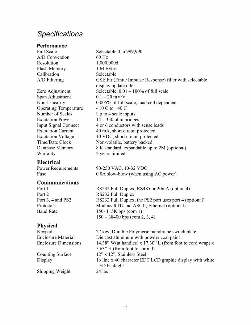
Specifications Performance Full Scale Selectable 0 to 999,990 A/D Conversion 60 Hz Resolution 1,000,000d Flash Memory 1 M Bytes Calibration Selectable A/D Filtering GSE Fir (Finite Impulse Response) filter with selectable
display update rate Zero Adjustment Selectable, 0.01 – 100% of full scale Span Adjustment 0.1 – 20 mV/V Non-Linearity 0.005% of full scale, load cell dependent Operating Temperature - 10 C to +40 C Number of Scales Up to 4 scale inputs Excitation Power 14 – 350 ohm bridges Input Signal Connect 4 or 6 conductors with sense leads Excitation Current 40 mA, short circuit protected Excitation Voltage 10 VDC, short circuit protected Time/Date Clock Non-volatile, battery backed Database Memory 8 K standard, expandable up to 2M (optional) Warranty 2 years limited
Electrical Power Requirements 90-250 VAC, 10-32 VDC Fuse 0.8A slow-blow (when using AC power)
Communications Port 1 RS232 Full Duplex, RS485 or 20mA (optional) Port 2 RS232 Full Duplex Port 3, 4 and PS2 RS232 Full Duplex, the PS2 port uses port 4 (optional) Protocols Modbus RTU and ASCII, Ethernet (optional) Baud Rate 150- 115K bps (com 1) 150 – 38400 bps (com 2, 3, 4)
Physical Keypad 27 key, Durable Polymeric membrane switch plate Enclosure Material Die cast aluminum with powder coat paint Enclosure Dimensions 14.38” W(at handles) x 17.30” L (from foot to cord wrap) x
5.63” H (from foot to shroud) Counting Surface 12” x 12”, Stainless Steel Display 16 line x 40 character EDT LCD graphic display with white
LED backight Shipping Weight 24 lbs

3
Enclosure The enclosure is made of die cast aluminum with rib enforcement. This design provides extra strength and durability. The enclosure is painted with powder coat and the counting surface is stainless steel. This enclosure also includes built in carrying handles and a line cord wrap for ease of portability.
Figure 1: Model 675 Enclosure Outline
Load Cell The load cell can be exchanged by removing two M6 1x 20mm (size) bolts from the bottom plate and two M6 1 x 16mm (size) bolts from the top spider assembly.
Figure 2: Load Cell Installation

4
When exchanging a load cell with another the overload stop and corner overloads must be reset. See the specifications below.
Table 1: Load Cell Overload Stops
LOAD CELL CONNECTIONS The load cell cable connects to J15 of the main board. The J15 connector is accessible from the load cell cavity of the Model 675 enclosure.
Table 2: Local Load Cell Connection to Main Board
Display A large 16 line x 40 character graphic LCD provides excellent visibility with user defined help screens and prompting. The large graphic display features a backlight for use in poorly lit areas.
Figure 3: Example of APW Lookup Display
Load Cell Stop Set to Load Cell Overload 120 % of full scale Corner Overloads 60 % of full scale
Pin designation Function 1 Shield 2 - Sense 3 + Sense 4 - Signal 5 + Signal 6 - Excitation 7 + Excitation

5
Keypad The Model 675 comes with a durable and versatile Polymeric switch plate with large keys for ease of use. The keypad is easily cleaned with a damp cloth or non-abrasive cleaner.
Figure 4: Model 675 Keypad
FUNCTIONS All of the keys perform different functions. Some keys have more than one function.
Act as soft keys which will perform a specific function. Refer to the text on the display for the function of each soft key.
Subtracts the weight of the tare from the displayed weight. Commonly used for removing the weight of a container.
Performs a gross zero and displays the gross mode.
Performs a sample for an accurate parts counting and calculates an average piece weight.
Toggles the units of measure between lb, kg, g, ounce, etc.
6
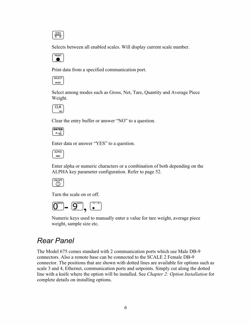
Selects between all enabled scales. Will display current scale number.
Print data from a specified communication port.
Select among modes such as Gross, Net, Tare, Quantity and Average Piece Weight.
Clear the entry buffer or answer “NO” to a question.
Enter data or answer “YES” to a question.
Enter alpha or numeric characters or a combination of both depending on the ALPHA key parameter configuration. Refer to page 52.
Turn the scale on or off.
- , Numeric keys used to manually enter a value for tare weight, average piece weight, sample size etc.
Rear Panel The Model 675 comes standard with 2 communication ports which use Male DB-9 connectors. Also a remote base can be connected to the SCALE 2 Female DB-9 connector. The positions that are shown with dotted lines are available for options such as scale 3 and 4, Ethernet, communication ports and setpoints. Simply cut along the dotted line with a knife where the option will be installed. See Chapter 2: Option Installation for complete details on installing options.

7
Figure 5: Model 675 Back Panel Label
Back Panel Connections Connections for a second scale, Com1 and Com 2 ports are standard with the Model 675. Connector pin outs are provided in the tables below. Refer to Table 4 below for the pin of Com 3 and Com 4 ports (optional).
Table 3: Scale 2 DB 9 Connector Pin Out
If a load cell with a 4 wire cable is being used jumpers will need to be installed between the sense and excitation. The jumpers will be installed on the DB9 connector being installed on the load cell cable. Refer to Table 3 for pin number designation.
Table 4: Communication Ports 1 -4 Pin Out
DB9 pin designation Function Load Cell Cable 1 + Signal 4 or 6 wire 2 - Signal 4 or 6 wire 3 + Sense 4 wire (connect a wire jumper to pin 8) 4 - Sense 4 wire (connect a wire jumper to pin 9) 5 - Excitation 4 or 6 wire 6 + Excitation 4 or 6 wire 7 Chassis Ground 4 or 6 wire 8 + Excitation 4 wire (connect a wire jumper to pin 3) 9 - Excitation 4 wire (connect a wire jumper to pin 4)
DB9 pin designation
Function Com 1
Function Com 2
Function Com 3
Function Com 4
1 No connection TTL No connection No connection 2 RXD RXD RXD RXD 3 TXD TXD TXD TXD 4 + 5V + 5V + 5V + 5V 5 ISO Ground Ground Ground Ground 6 Ground Ground Ground Ground 7 RTS RTS No connection No connection 8 CTS CTS CTS No connection 9 Remote Key 1 Remote Key 2 No connection No connection
Standard Options Options

8
CHAPTER 2: OPTION INSTALLATION Options may be installed in several different configurations. This chapter will provide detailed instructions on installing each option. Additional hardware may be needed depending on which options you will be installing.
Table 5: Additional Parts List
Part # 299290-41108 should only be used for connecting to a third scale. Do not use this cable to connect setpoints. This could cause severe damage due to high voltages and void the factory warranty.
BATTERY
Rechargeable Battery Option Installation The rechargeable battery option kits (24675B-120B0) 24 hour or (24675B-121B0) 12 hour provide remote operation for parts counting. Simply plug the Model 675 into an AC outlet to recharge the battery pack. The battery packs need to be cycled every thirty days to ensure the longest possible battery shelf life.
Table 6: 12 Hour Rechargeable Battery Pack Kit Parts List
Part Number Description Used for 22-30-3061 18” ribbon
cable Connects multi-scale and setpoint options to the main board
26-20-1870 Strain Reliefs Connecting wiring to setpoint or multi-scale option
299290-41108 DB9 to pigtail cable
Third scale multi-scale option connection
Quantity Part Number Description 1 12-10-41003 Battery pack, 12 Volt 1 44-25-40738 Battery door 1 420994-41088 Battery charging board 1 299290-41132 Interface Cable 2 31-80-7580 Velcro 2 31-80-7600 Velcro 1 28-10-41004 Warning Decal 4 17-40-2579 Standoffs 2 38-26-8112 M4 x 0.7 x 10 mm screw 2 42-50-0070 Battery door foam

9
Table 7: 28 Hour Rechargeable Battery Pack Kit Parts List
INSTALLATION INSTRUCTIONS 1. DISCONNECT POWER! UNPLUG THE MODEL 675 TO INSURE DAMAGE
WILL NOT OCCUR DURING OPTION INSTALLATION. 2. Remove the (6) 38-31-8710 M5 x 0.8 x 10 mm screws from the enclosure bottom
plate and set it aside. 3. Install the battery charging board by installing the (4) 17-40-2579 nylon standoffs
onto the enclosure bottom plate. 4. Align the battery charging board on the standoffs so that the J2 connector shows
through the rectangle knockout on the enclosure bottom plate. 5. Gently snap the battery charging board onto the standoffs.
Be sure the Model 675 is turned off before connecting the battery to the battery charging board.
6. Connect 299290-41132 battery interface cable from J1 of the battery charging
board to J3 of the main board. 7. Reinstall the bottom plate to the enclosure with the (6) 38-31-8710 M5 x 0.8 x 10
mm screws that were removed in step 1. 8. Install the hook sided Velcro to the battery cavity. 9. Install the soft-sided Velcro to the battery making sure it is lined up with the
Velcro that was placed in the battery cavity. 10. Connect the battery cable to the J2 connector of the battery charging board. 11. Place the battery in the battery cavity. 12. Install the (2) strips of foam on the battery door. 13. Reinstall the enclosure bottom plate to the enclosure. 14. Install the battery door by aligning the (3) tabs of the battery door with the (3)
slots of the enclosure bottom plate and push the tabs into the slots. The battery door is raised on the end with the screw holes. Make sure the raised portion of the door is up insuring the battery door is flush.
Quantity Part Number Description 1 12-10-41087 Battery pack, 9.6 Volt 1 44-25-40738 Battery door 1 420994-40751 Battery charging board 1 299290-41132 Interface cable 2 31-80-7580 Velcro 2 31-80-7600 Velcro 1 28-10-41004 Warning Decal 4 17-40-2579 Standoffs 2 38-26-8112 M4 x 0.7 x 10 mm screw 2 42-50-0070 Battery door foam

10
15. Install (2) 38-26-8112 screws to the battery door and fasten the battery door to the bottom plate.
16. Some older models will not have threaded holes in the bottom cover plate. Use 38-26-8112 self-tapping screw to create thread. Remove and install thumbscrews.
Figure 6: Rechargeable Battery Installation
BATTERY STATUS ICONS The rechargeable batteries will show different battery states during charging and discharging.
No Battery Option Installed The charging board is physically not installed or recognized. No graphic will be displayed
Battery Discharging The battery icons will run through a succession of animation from 100% to 0%.
Battery Disconnected
Once the battery is disconnected, the current battery icon will disappear.
Charge Pending The Model 675 has been plugged into a power outlet. This only appears for a few seconds when AC power is applied.
The 28 hour and 12 hour batteries are not interchangeable. The connectors on both options are different to avoid damaging the battery pack and/or battery charging board.
100 % 75 % 50 % 25 % 0 %

11
Charging Battery The battery icons will run through a succession of animation from 0% to 100%.
Fully Charged The display will show a battery icon of 100%.
Low Battery Condition
When the battery voltage reaches a low battery condition the battery icon will cycle between 25%, 0%, blank. It is recommended that the Model 675 be plugged into an outlet within 10 minutes to recharge the battery so data is not lost .
Non-Rechargeable Battery Option Installation This option (24675B-301B0) is used for installation of non-rechargeable D cell batteries only. DO NOT attempt to charge non-rechargeable D cell batteries. There is no battery status indication with the non-rechargeable battery option. Also the display will go dim when the batteries achieve a low battery status.
Table 8: Rechargeable Battery Pack Kit Parts List
INSTALLATION INSTRUCTIONS 1. DISCONNECT POWER! UNPLUG THE MODEL 675 TO INSURE
DAMAGE WILL NOT OCCUR DURING OPTION INSTALLATION. 2. Remove the (6) 38-31-8710 M5 x 0.8 x 10 mm screws from the bottom plate
set it aside.
0 % 25 % 50 % 75 % 100 %
25 % 0 %
Quantity Part Number Description 1 44-25-40738 Battery door 1 299290-41024 Battery holder assembly 2 38-26-2100 Thumb screw 1 28-10-41004 Warning Decal 2 38-21-2610 M3 screw 2 42-50-0070 Battery door foam 1 38-26-8112 M4 screw

12
3. Attach the battery tray to the battery holder cavity of the bottom plate using (2) 38-21-2610 self-tapping screws. The cable of the battery holder needs to face the slot in the battery holder cavity.
4. Put the rubber grommet of the battery holder cable into the slot of the battery holder cavity.
5. Connect the battery cable to J3 (battery connector) of the main board. 6. Reinstall the bottom plate to the enclosure with the (6) 38-31-8710 M5 x 0.8 x
10 mm screws that were removed in step 1. 7. Install the (2) strips of foam lengthwise to the battery door. 8. Install the battery door by aligning the (3) tabs of the battery door with the (3)
slots of the enclosure bottom plate and push the tabs into the slots. The battery door is raised on the end with the screw holes. Make sure the raised portion of the door is up insuring the battery door is flush.
9. Install (2) 38-31-8750 thumbscrews to the battery door and fasten the battery door to the bottom plate.
10. Some older models will not have threaded holes in the bottom cover plate. Use 38-26-8112 self-tapping screw to create thread. Remove and install thumbscrews.
Figure 7: Installing the Non-Rechargeable Battery Holder
OPTION MOUNTING BRACKET The option mounting bracket kit is required for option installation. The bracket will accommodate up to two of the following options: Ethernet Module, Multi-scale, RS-232/PS2, Setpoint. The options mount on the bracket with the hardware provided with each option kit.
Table 9: Option Mounting Bracket Kit Parts List (24675B-300A0)

13
INSTALLATION INSTRUCTIONS 1. DISCONNECT POWER! UNPLUG THE MODEL 675 TO INSURE DAMAGE
WILL NOT OCCUR DURING OPTION INSTALLATION. 2. Install all options on the mounting bracket. Refer to the specific option section for
installation instructions. 3. Remove the (6) 38-31-8710 M5 x 0.8 x 10 mm screws from the enclosure bottom
plate and set it aside. 4. Use the (2) M5 self-tapping screws to fasten the option-mounting bracket to the
Model 675 enclosure. For the installation drawing refer to Figure 8. 5. Reinstall the enclosure bottom plate.
Figure 8: Installing the Option Mounting Bracket
Use caution when removing the bottom plate. Do not rest the scale upside down on the top plate. This may cause excessive damage to low capacity load cells.
REMOTE SCALE
Third Scale Option The remote scale kit (24660B-200B0) provides a third scale input to be used with a remote scale. This option installs on the option-mounting bracket (see page 12). The 299229-41108 DB9 multi-scale option cable can be connected to the back panel for load
Quantity Part Number Description 1 44-25-40951 Mounting Plate 2 38-31-8710 M5 self tapping screw

14
cell connection. The 10” option ribbon cable (22-30-35454) is needed to connect the option to the main board.
Table 10: Third Scale Option Kit Parts List
INSTALLATION INSTRUCTIONS
Be sure to install the SBM modules first on the option-mounting plate.
1. DISCONNECT POWER! UNPLUG THE MODEL 675 TO INSURE DAMAGE
WILL NOT OCCUR DURING OPTION INSTALLATION. 2. Remove the (6) 38-31-8710 M5 x 0.8 x 10 mm screws from the enclosure bottom
plate and set it aside. 3. Find the side of the option mounting bracket that is labeled with OPT. You will
find this label in two spots on this side. 4. Line up the holes of the multi-scale option board with the holes located on the
right side of the notch on the option-mounting bracket. 5. Install the (4) aluminum standoffs in the holes with the (4) screws on the
underside of the bracket (labeled ETH). Refer to Figure 9 for configuration. 6. Position the Multi-Scale Option on the standoffs so the ribbon cable points away
from the notch on the option-mounting bracket. Install the (4) hex nuts to secure the option board.
Figure 9: Remote Scale Installation
Quantity Part Number Description 1 420919-36553 Multi-scale option board 4 17-20-3019 Aluminum standoffs 4 38-21-1640 Hex nuts 4 38-21-0101 Screws
Remote Scale Remote Scale

15
7. Connect the 10” option ribbon cable 22-30-35454 (optional) from J1 of the multi-scale option board to J1 of the main board.
8. Connect the load cell to J3 of the multi-scale option board. 9. Install the option-mounting bracket in the Model 675 enclosure. Refer to page 13
for option mounting bracket installation instructions. 10. Reinstall the enclosure bottom plate.
Fourth Scale Option Provides a fourth scale input to be used with a remote scale. Use either the AUX 2 or AUX 3 ports on the back panel for load cell connection. Use a 26-20-1870 strain relief.
Table 11: Forth Scale Option Kit Parts List
INSTALLATION INSTRUCTIONS 1. DISCONNECT POWER! UNPLUG THE MODEL 675 TO INSURE
DAMAGE WILL NOT OCCUR DURING OPTION INSTALLATION. 2. Remove the (6) 38-31-8710 M5 x 0.8 x 10 mm screws from the enclosure
bottom plate and set it aside. 3. Find the side of the option mounting bracket that is labeled with OPT. You
will find this label in two spots on this side. 4. Line up the holes of the multi-scale option board with the holes located on the
right side of the notch on the option-mounting bracket. 5. Install the (4) aluminum standoffs in the holes with the (4) screws on the
underside of the bracket (labeled ETH). Refer to Figure 9 for configuration. 6. Position the Multi-Scale Option on the standoffs so the ribbon cable points
away from the notch on the option-mounting bracket. Install the (4) hex nuts to secure the option board.
7. If more than one SBM module is being used, connect the 6” option ribbon cable from J1 to J2 of the next option.
8. The last option in the chain will use a 22-30-35454 10” ribbon cable (optional) to connect the option board to the main board.
9. Reinstall the enclosure bottom plate.
Quantity Part Number Description 1 420919-36553 Multi-scale option board 4 17-20-3019 Aluminum standoffs 4 38-21-1640 Hex nuts 4 38-21-0101 Screws

16
COMMUNICATION
RS- 485 Networking This section describes the installation of the RS-485 module. Installing this module will convert com port 1 from RS-232 to RS-485. Refer to page 51 for more details on the RS-485 parameter and where to set the network address.
INSTALLATION INSTRUCTIONS 1. DISCONNECT POWER! UNPLUG THE MODEL 675 TO INSURE DAMAGE
WILL NOT OCCUR DURING OPTION INSTALLATION. 2. Remove the (6) 38-31-8710 M5 x 0.8 x 10 mm screws from the enclosure bottom
plate and set it aside. 3. Remove the U43 IC on the main board from its socket. 4. Remove the white wire jumper from the IC socket where the chip in step 2 was
removed. 5. Snap the plastic spacers into the three mounting holes surrounding the U43 socket on
the main board. 6. Gently press the option board into the socket. 7. Apply the included label to the outside of the enclosure. 8. Reinstall the enclosure back plate.
Figure 10: Installing the RS-485 Option The RS-485 module does not have to be enabled in the setup mode. The module simply converts the standard RS-232 communication on com port 1 to RS-485. However the advantage of using the RS-485 module, aside from the ability to transmit over long distances, is the ability to network multiple indicators or parts counters using the same communication wires. When networking indicators, it is necessary to set up a network address for each indicator. The network module itself does not require addressing, rather each indicator must be enabled for network addressing in the setup mode. The RS-485 parameter (P250) must be enabled and the network address (P251) must be set.

17
Half-Duplex (2-wire) Installing jumpers 1, 2 and 4 on the RS-485 option board electrically connects pin RX B(+) to pin TX B(+), and pin RX A(-) to pin TX A(-) on the option board. This effectively provides two + and two - pin connections, enabling easy connection of network lines in parallel from device to device without having to position two wires into the same lever socket. A B(+) line from each device on the network should be connected in parallel to the next device on the network. This is also true for all A(-) lines.
The units inside the two end-points of the network loop will utilize both A(-) pin connections and both B(+) pin connections. The units at the end-points of the network will utilize only one A(-) pin connection and one B (+) pin connection.
Full Duplex (4-wire) Removing jumpers 1, 2 and 4 on the RS-485 option board requires that the transmit and receive lines be wired independently of one another. The RX B(+) and RX A(-) receive lines must be wired in parallel to the next device’s RX B(+) and RX A(-) receive lines , and the TX B(+) and TX A(-) transmit lines must be wired in parallel to the next device’s TX B(+) and TX A(-) transmit lines.
In order to connect network lines in parallel from device to device it is necessary to position two wires into the same lever socket. This requires that the wire used to build the network be 24AWG or smaller to allow both wires to fit into the same lever socket. Both Half Duplex and Full Duplex
The network boards on both end-points should install jumper 3 on the RS-485 option board to engage the 120 Ω termination resistor (R8). The boards between the two end- points should remove jumper 3 on the RS-485 option board.
The isolated ground (ISO GND) should be connected in parallel from unit to unit. A shielded twisted two pair cable is recommended throughout the network.

18
20 mA Current Loop Operation This section describes the installation of the 20mA Current Loop module. Installing this module will convert com port 1 from RS-232 to 20mA current loop (not to be confused with 0-20mA or 4-20mA analog output).
INSTALLATION INSTRUCTIONS 1. DISCONNECT POWER! UNPLUG THE MODEL 675 TO INSURE DAMAGE
WILL NOT OCCUR DURING OPTION INSTALLATION. 2. Remove the (6) 38-31-8710 M5 x 0.8 x 10 mm screws from the enclosure bottom
plate and set it aside. 3. Remove the U43 IC on the main board from its socket. 4. Remove the white wire jumper from the IC socket where the chip in step 2 was
removed. 5. Snap the plastic spacers into the three mounting holes surrounding the U43 socket
on the main board. 6. Gently press the option board into the socket. 7. Apply the included label to the outside of the enclosure. 8. Reinstall the enclosure back plate.
Figure 11: 20 mA Current Loop Installation 20mA Parameter Setup The 20mA module does not have to be enabled in the setup mode. The module simply converts the standard RS-232 communication on com port 1 to 20mA current loop. 20 mA Current Loop Connections Apply the label to the outside of the Model 675 enclosure.

19
Transmit Current Input Active = TA Transmit Current Input Passive = TP Transmit Output = TXO Receive Current Input = RXI Receive Current Output = RX The signal is bi-directional. Both the transmit output and the receive input of the indicator are available as 20 mA signals. The handshaking signals are not supported by the 20 mA current loop. Only baud rates of 9600 or less are supported.
The TXO output may be used as an active or passive output from the Model 675. Either active or passive is chosen depending upon which terminals are used for the connections. In active mode the indicator supplies the current. In passive mode, the external device supplies the current. The RX input is available in passive mode only.
The input and output are electrically isolated from the main boards, earth ground and each other. This applies for both passive and active modes. Isolation is a minimum of 1000 volts.
The active mode transmit current loop provides a driving voltage of 12 VDC. This will allow 20 mA current flow with up to a 600 ohm load. Passive mode will work with an external driving voltage of up to 50 VDC.
Ethernet Interface Module The Ethernet Interface Module allows communication across an intranet or internet connection. The Ethernet Module will use communication port 3 as its connection.
Table 12: Ethernet Interface Module Kit Parts List (24675B-400C0)
INSTALLATION INSTRUCTIONS 1. DISCONNECT POWER! UNPLUG THE MODEL 675 TO INSURE
DAMAGE WILL NOT OCCUR DURING OPTION INSTALLATION. 2. Remove the (6) 38-31-8710 M5 x 0.8 x 10 mm screws from the enclosure
bottom plate and set it aside.
Quantity Part Number Description 1 41-42-8410P Ethernet Module 1 39-10-40305 Users Guide 3 17-40-2578 Nylon spacers 1 17-20-3025 Nylon Standoff 1 38-21-1643 Nylon Hex Nut 1 38-21-0101 screw 1 22-30-31157 2x5 interface cable

20
Be sure to install the SBM modules first on the option-mounting plate.
3. Locate the portion of the option-mounting bracket that is labeled ETH. Notice that there are (8) mounting holes.
4. Install (2) nylon spacers in the holes closest to the edge of the notched side of the option-mounting bracket.
5. Install the other (1) nylon spacer in the hole furthest from the back edge. 6. Place the nylon standoff under the left edge of the Ethernet board and fasten
the standoff with the screw from underneath the option-mounting bracket. 7. Position the Ethernet Interface Module so that the LED’s and RJ45 jack face
the same edge as the notch. Install the Ethernet Interface Module on the (3) spacers and (1) standoff. Place the nylon hex nut on the screw post of the nylon standoff and tighten the hex nut. Refer to Figure 12 for illustration.
Figure 12: Ethernet Option Installation
Be sure to install the SBM modules first on the option-mounting plate.
8. Make sure to cut out the rear label to match the installed options. For the
Ethernet Interface Module cut out the dotted line label Ethernet. Refer to the back panel on page 6.
9. Install the option-mounting bracket in the Model 675 enclosure with the (2) 38-31-8710 self-tapping screws included with the option mounting bracket kit. Refer to page 13 for installation instructions.
10. If the Ethernet Module and RS-232/PS2 option are both installed, connect the 9” ribbon cable from J5 of the Ethernet Module to J4 of the RS-232/PS2 Module. Then connect the 9” ribbon cable which came with the RS-232/PS2 Module from J2 of the RS-232/PS2 Module to J18 of the main board. Refer to Figure 13 for illustration.
Nylon Standoff
Nylon Hex Nut
Screw

21
11. If the Ethernet Module is the only communication option being installed, connect the 9” ribbon cable from J5 of the Ethernet Module to J18 of the main board.
12. Make sure to remove the jumper from JP3 if it is installed.
Figure 13: Connecting the Ethernet Module to the Main Board
Figure 14: Ethernet and RS-232/PS2 Modules
RS-232/PS2 Module The RS-232/PS2 Module provides communication ports 3 and 4. If the PS2 connection is used, it will automatically be assigned communication port 4 and the DB 9 of communication port 4 will not be recognized. An option-mounting bracket (24675B-300A0) is required to install this option.
Do not connect the Ethernet Module or RS-232 Module cables to the J4 BDM connector on the main board. This connection will cause damage to the main board making the Model 675 inoperable.
Ethernet
RS232 Expansion
22
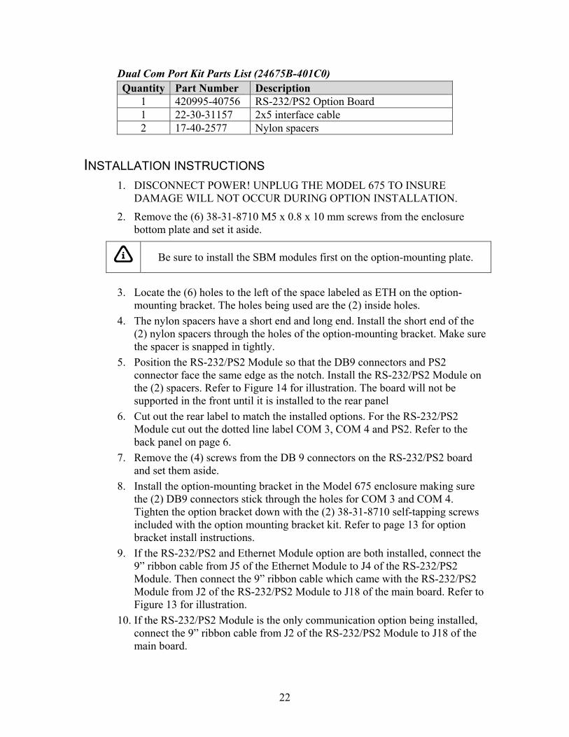
Dual Com Port Kit Parts List (24675B-401C0)
INSTALLATION INSTRUCTIONS 1. DISCONNECT POWER! UNPLUG THE MODEL 675 TO INSURE
DAMAGE WILL NOT OCCUR DURING OPTION INSTALLATION.
2. Remove the (6) 38-31-8710 M5 x 0.8 x 10 mm screws from the enclosure bottom plate and set it aside.
Be sure to install the SBM modules first on the option-mounting plate.
3. Locate the (6) holes to the left of the space labeled as ETH on the option-
mounting bracket. The holes being used are the (2) inside holes. 4. The nylon spacers have a short end and long end. Install the short end of the
(2) nylon spacers through the holes of the option-mounting bracket. Make sure the spacer is snapped in tightly.
5. Position the RS-232/PS2 Module so that the DB9 connectors and PS2 connector face the same edge as the notch. Install the RS-232/PS2 Module on the (2) spacers. Refer to Figure 14 for illustration. The board will not be supported in the front until it is installed to the rear panel
6. Cut out the rear label to match the installed options. For the RS-232/PS2 Module cut out the dotted line label COM 3, COM 4 and PS2. Refer to the back panel on page 6.
7. Remove the (4) screws from the DB 9 connectors on the RS-232/PS2 board and set them aside.
8. Install the option-mounting bracket in the Model 675 enclosure making sure the (2) DB9 connectors stick through the holes for COM 3 and COM 4. Tighten the option bracket down with the (2) 38-31-8710 self-tapping screws included with the option mounting bracket kit. Refer to page 13 for option bracket install instructions.
9. If the RS-232/PS2 and Ethernet Module option are both installed, connect the 9” ribbon cable from J5 of the Ethernet Module to J4 of the RS-232/PS2 Module. Then connect the 9” ribbon cable which came with the RS-232/PS2 Module from J2 of the RS-232/PS2 Module to J18 of the main board. Refer to Figure 13 for illustration.
10. If the RS-232/PS2 Module is the only communication option being installed, connect the 9” ribbon cable from J2 of the RS-232/PS2 Module to J18 of the main board.
Quantity Part Number Description 1 420995-40756 RS-232/PS2 Option Board 1 22-30-31157 2x5 interface cable 2 17-40-2577 Nylon spacers

23
Do not connect the Ethernet Module or RS-232 Module cables to the J4 BDM connector on the main board. This connection will cause damage to the main board making the Model 675 inoperable.
DATABASE OPTION The database option offers more memory storage for creating reports and tracking inventory.
Database Option Parts List
INSTALLATION INSTRUCTIONS 1. DISCONNECT POWER! UNPLUG THE MODEL 675 TO INSURE DAMAGE
WILL NOT OCCUR DURING OPTION INSTALLATION. 2. Remove the (6) 38-31-8710 M5 x 0.8 x 10 mm screws from the enclosure bottom
plate and set it aside. 3. Locate the J9 database header on the main board. There are three holes for the
database mounting hardware within the silk-screened rectangle on the main board. 4. Insert a M3 x 0.5 x 6mm screw through one of the mounting holes of the main
board with the screw head on the underneath side of the main board and hold it in place with your finger.
5. Install a 17-20-3001 aluminum standoff by hand until it is finger tight on the M3 x 0.5 x 6mm screw and tighten with a 6 mm nut driver.
6. Repeat steps 3 and 4 for the remaining screws and standoffs. 7. Place the database option board on the aluminum standoffs and secure with (3)
5.5 mm hex nuts. 8. Reinstall the enclosure bottom plate.
Quantity Part Number Description 1 420916-36371
420916-36372 420916-36373
256 K 1 Meg 2 Meg
3 17-20-3001 Aluminum standoffs 3 38-21-1640 M3 x 5.5mm hex nuts 3 38-21-0101 M3 x 0.5 x 6mm screws
24
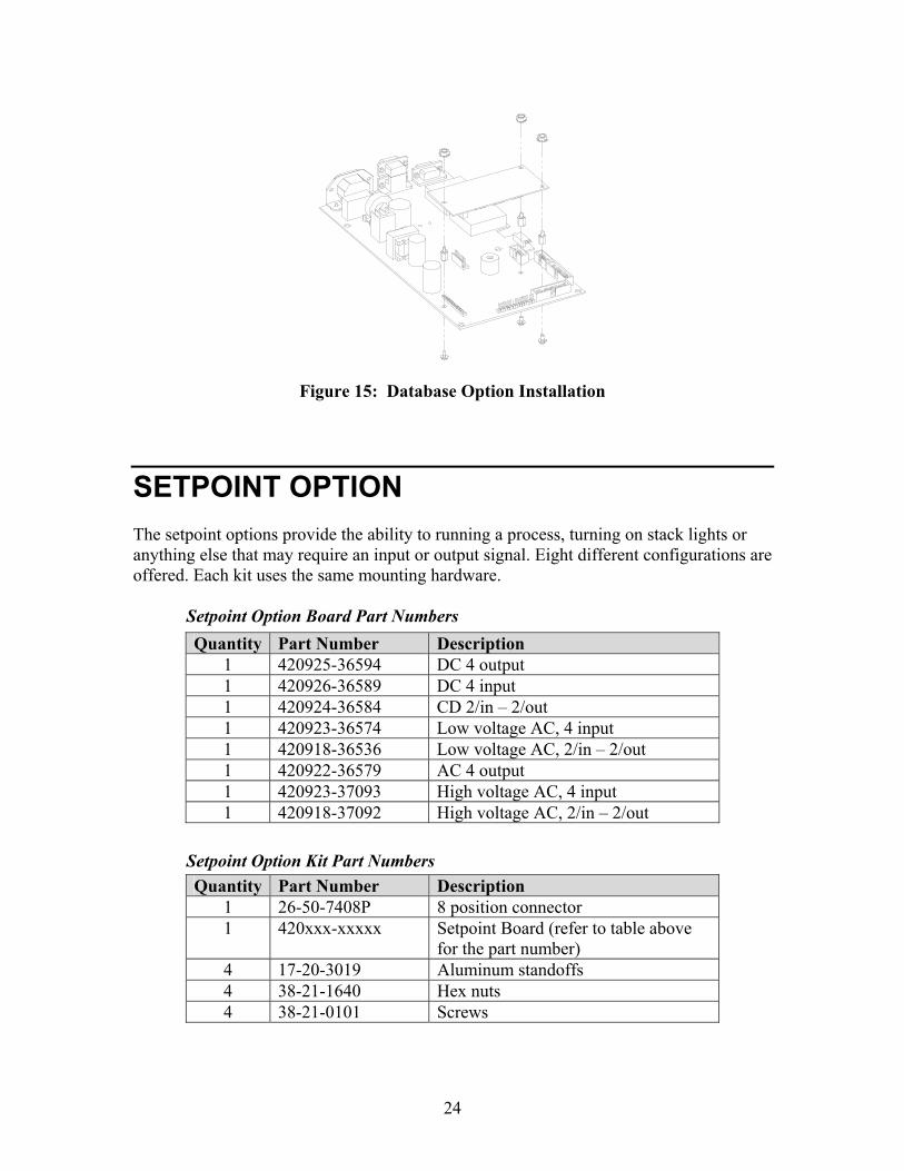
Figure 15: Database Option Installation
SETPOINT OPTION The setpoint options provide the ability to running a process, turning on stack lights or anything else that may require an input or output signal. Eight different configurations are offered. Each kit uses the same mounting hardware. Setpoint Option Board Part Numbers Setpoint Option Kit Part Numbers
Quantity Part Number Description 1 420925-36594 DC 4 output 1 420926-36589 DC 4 input 1 420924-36584 CD 2/in – 2/out 1 420923-36574 Low voltage AC, 4 input 1 420918-36536 Low voltage AC, 2/in – 2/out 1 420922-36579 AC 4 output 1 420923-37093 High voltage AC, 4 input 1 420918-37092 High voltage AC, 2/in – 2/out
Quantity Part Number Description 1 26-50-7408P 8 position connector 1 420xxx-xxxxx Setpoint Board (refer to table above
for the part number) 4 17-20-3019 Aluminum standoffs 4 38-21-1640 Hex nuts 4 38-21-0101 Screws

25
INSTALLATION INSTRUCTIONS 1. DISCONNECT POWER! UNPLUG THE MODEL 675 TO INSURE
DAMAGE WILL NOT OCCUR DURING OPTION INSTALLATION 2. Remove the (6) 38-31-8710 M5 x 0.8 x 10 mm screws from the enclosure
bottom plate and set it aside. 3. Find the side of the option mounting bracket that is labeled with OPT. You
will find this label in two spots on this side. 4. Line up the holes of the setpoint option board with the holes located on the
right side of the notch on the option-mounting bracket. 5. Install the (4) aluminum standoffs in the holes with the (4) screws on the
underside of the bracket (labeled ETH). 6. Position the Setpoint Option Board on the standoffs so the ribbon cable points
away from the notch on the option-mounting bracket. Install the (4) hex nuts to secure the option board.
7. If more than one SBM module is being used, connect the 6” option ribbon cable from J1 to J2 of the next option.
8. The last option in the chain will use a 22-30-35454 10” ribbon cable (optional) to connect the option board to the main board.
9. Install the option-mounting bracket in the Model 675 enclosure. Refer to page 13 for option mounting bracket installation instructions.
10. Connect all necessary wiring to the Setpoint Option Board. 11. Reinstall the enclosure bottom plate.
Figure 16: Setpoint Option Mounting
26
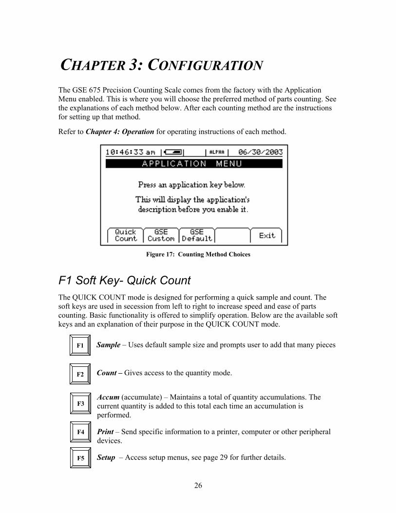
CHAPTER 3: CONFIGURATION The GSE 675 Precision Counting Scale comes from the factory with the Application Menu enabled. This is where you will choose the preferred method of parts counting. See the explanations of each method below. After each counting method are the instructions for setting up that method.
Refer to Chapter 4: Operation for operating instructions of each method.
Figure 17: Counting Method Choices
F1 Soft Key- Quick Count The QUICK COUNT mode is designed for performing a quick sample and count. The soft keys are used in secession from left to right to increase speed and ease of parts counting. Basic functionality is offered to simplify operation. Below are the available soft keys and an explanation of their purpose in the QUICK COUNT mode.
Sample – Uses default sample size and prompts user to add that many pieces
Count – Gives access to the quantity mode.
Accum (accumulate) – Maintains a total of quantity accumulations. The current quantity is added to this total each time an accumulation is performed.
Print – Send specific information to a printer, computer or other peripheral devices.
Setup – Access setup menus, see page 29 for further details.
F1
F2
F5
F3
F4

27
Setup the QUICK COUNT Mode
1. Press from the APPLICATION MENU. The display will come up with an explanation of the QUICK COUNT menu.
2. At this time you can choose the QUICK COUNT mode by pressing the
(YES) or return to the APPLICATION MENU by pressing the softkey
(Exit) or (NO).
3. The QUICK COUNT file will load automatically and return to the QUICK COUNT mode.
F2 Soft Key- GSE Custom Presently APW LOOKUP is the only application offered under GSE Custom. New modes will be added in the near future. Please check out the GSE website gse-inc.com for new updates.
The APW LOOKUP offers the flexibility of storing and recalling part numbers. The average piece weight and part description will be stored and recalled with the part number.
APW LOOKUP Sample - Uses default sample size and prompts user to add that many pieces.
Store – Store a part number with average piece weight and description.
Rec/New – Add a new part number or recall a part number from the database.
Desc – Add a part description.
Setup - Access setup menus, see page 32 for further details.
Setup the APW LOOKUP Mode
1. Press the from the APPLICATION MENU. The display will come up with an explanation of the APW LOOKUP menu.
F2
F4
F5
F3
F1

28
2. At this time you can choose the APW LOOKUP mode by pressing the
(YES) or return to the menu choices by pressing the softkey (Exit) or (NO).
3. The APW LOOKUP file will load and will return to the APW LOOKUP mode.
F3 Soft Key- GSE Default If the preprogrammed applications are not going to be used, than the Model 675 should be factory defaulted. This mode will reset the Model 675 to GSE factory default status. The preset applications will be lost but can be reestablished at parameter 65002 (See technical reference manual for more details).
The Model 675 can still be used as a parts counter after it is factory defaulted. Refer to page 57 for more details on simple counting. Setup the GSE DEFAULT Mode
1. Press from the APPLICATION MENU prompt. The display will give an explanation of the GSE DEFAULT.
2. Press (YES) to accept the choice of GSE DEFAULT and continue or press
to cancel the default and return to the APPLICATION MENU.
3. If you chose to continue with the default in step 2 the display will ask ARE YOU
SURE? Either press (YES) to default the unit or press to cancel the default and return to the APPLICATION MENU.

29
Quick Count Configuration Setup Menu Use the F5 Setup key from the QUICK COUNT screen to gain access to different menus.
SETUP This menu was designed for accessing the items that will need to be changed the most often. Below is an explanation of the choices in the menu. Follow the instructions on the display for each key.
PARAMETER DESCRIPTION DEFAULT SETTING KEYPRESSES
CHANGE SAMPLE
Change the default sample size
10 Key in new sample size and press Enter to accept or F5 to escape
CLEAR TOTALS
Clears the accumulation registers
Not applicable Press Enter to clear totals or Clr to escape
KEY-IN APW Key in an average piece weight for sample
0 Key in new average piece weight and press Enter or F5 to escape
SETUP MENUS Continues on to the Setup Menus
Not applicable
Change Sample
Clear Totals
Key-In APW
Setup Menus
Exit
F1 F2 F3 F4 F5
Cal Display Style
Print Formats
Advance Setup
Exit
F1 F2 F3 F4 F5
See page 37 for complete details on the Advanced Setup Menu.
The YES key is the NO key is .
Setup F5

30
SETUP MENUS This is the next level of menus, which offer more advanced setup.
PARAMETER DESCRIPTION DEFAULT SETTING KEYPRESSES
CAL Calibration any of the enabled scales
Not applicable Key in access code and press Enter or press F5 to escape
DISPLAY STYLE
Chose how the display will appear
Display Style 2 Press either F1 or F2 to chose the desired display style or F5 to escape
PRINT FORMATS
Chose a preformatted printout
Print Style 1 Use F3 and F4 to view print format choices. Press F5 to save the format
ADVANCE SETUP
Continues on to the Advanced Setup Menu
Not applicable See page 37
CAL (CALIBRATION) Refer to Chapter 5: Calibration on page 59 for complete instructions on calibrating the Model 675.
DISPLAY STYLE Choose one of the display types and press (EXIT) to save the change and return to the main menu. STYLE 1 – This is the classic GSE 2x5 display. The weight or quantity will be displayed in larger font while the prompts will be to the right of the weight display. STYLE 2 – This style incorporates the classic GSE 2x5 display along with two smaller
displays which will show other parameters. Press the key from the QUICK COUNT to toggle through the different parameter choices.
Large display Small Display Small Display Gross Net Tare Quantity Net Tare Quantity Net Piece Weight Quantity Tare Piece Weight Quantity Accuracy Piece Weight Quantity Accuracy Sample Size Quantity Sample Size Piece Weight Quantity Quantity Total Number of Accums

31
PRESET PRINTOUTS The preset print formats are viewable on the LCD display. Use the left arrow and
right arrow keys to view all transmit styles. Chose the desired format by viewing it
on the screen. Press the (EXIT) key to save the format and return to the main menu. Choice 1 Choice 2
Choice 3 Choice 4
Choice 5 Choice 6
Choice 7
Quantity: 30 APW: 0.1234 Tare: 1.515 lb
Quantity: 30 APW: 0.1234 Tare: 1.515 10:10:00 07/10/2003
Quantity: 30 Tare: 1.515 Scale # 2
Part#: Quantity 55 APW 0.4481 Tare 1.623
10.025 lb Gross 2.500 lb Tare 7.525 lb Net
Quantity: 55 QTY Total: 510 Total Accums: 10
Part#: Quantity 55 APW 0.4481 Tare 1.623 10:10:00 07/10/2003

32
APW Lookup Configuration Setup Menu Use the F5 Setup key from the APW LOOKUP screen to gain access to different menus.
Change Sample
Delete Part#
Key-In APW
Setup Menus
Exit
F1 F2 F3 F4 F5
Cal Display Style
Print Menu
Advance Setup
Exit
F1 F2 F3 F4 F5
Print Part#s
D-Load Part#s
Print Formats
Exit
F1 F2 F3 F4 F5
See page 37 for complete details.
Comm 1
Comm 2
Display Exit
F1 F2 F3 F4 F5
Comm 1
Comm 2
Exit
F1 F2 F3 F4 F5
SetupF5

33
SETUP This menu was designed for accessing the items that will need to be changed the most often. Below is an explanation of the choices in the menu. Follow the instructions on the display for each key.
PARAMETER DESCRIPTION DEFAULT SETTING KEYPRESSES
CHANGE SAMPLE
Change the default sample size
10 Key in new sample size and press Enter to accept or F5 to escape
DELETE PART #
Delete specified part number
Will not show until a part number is established
Key in part # and press F3. Press F5 to enter the setup. Press F2 to delete part #.
KEY-IN APW Key in an average piece weight for sample
0 Key in new average piece weight and press Enter or F5 to escape
SETUP MENUS Continues on to the Setup Menus
Not applicable Press F4 to continue
SETUP MENUS This is the next level of menus, which offer more advanced setup.
PARAMETER DESCRIPTION DEFAULT SETTING KEYPRESSES
CAL Calibration any of the enabled scales
Not applicable Key in access code and press Enter or press F5 to escape
DISPLAY STYLE
Chose how the display will appear
Style 2 Press either F1 – F4 to chose the desired display style or F5 to escape
PRINT MENU Choose what information to print out
Not applicable Continues on to the Print Menu selections
ADVANCE SETUP
Continues on to the Advanced Setup Menu
Not applicable See page 37
CAL (CALIBRATION) Refer to Chapter 5: Calibration on page 59 for complete instructions on calibrating the Model 675.
The YES key is the NO key is .
34
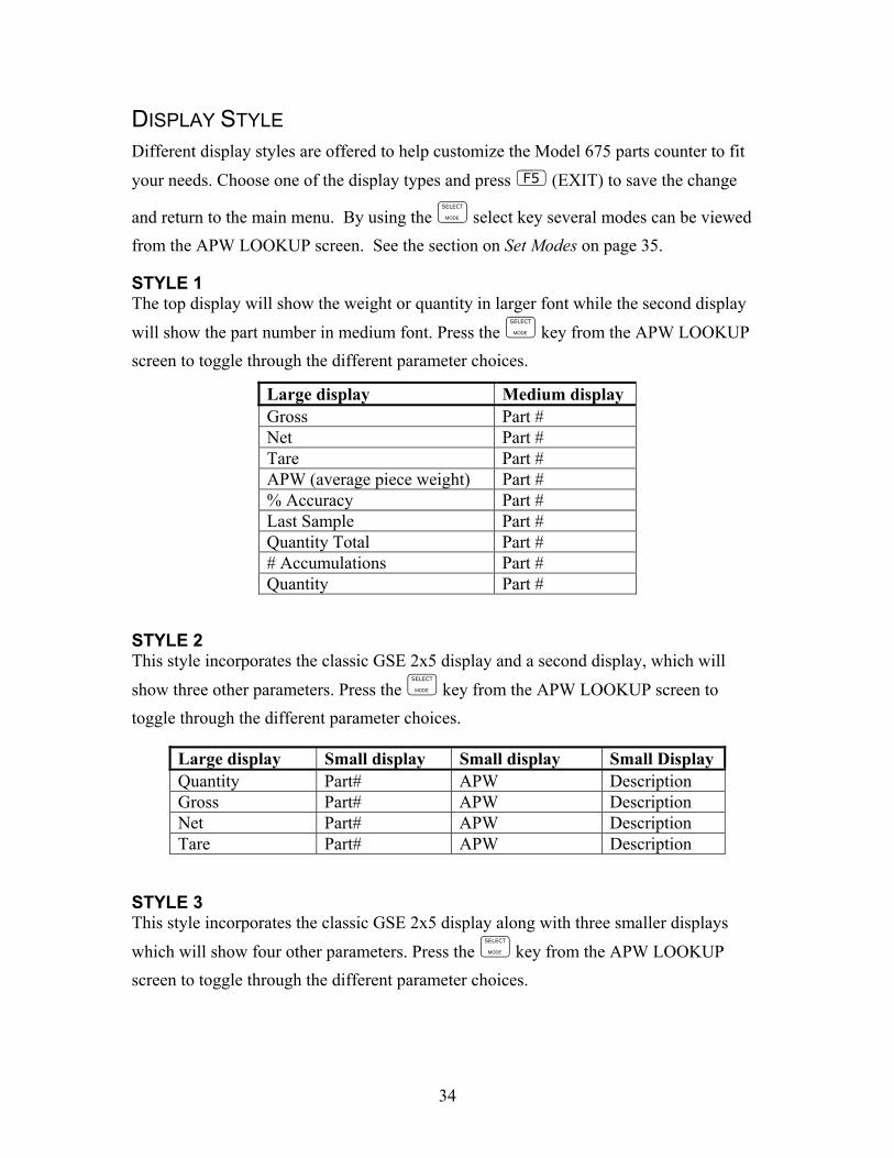
DISPLAY STYLE Different display styles are offered to help customize the Model 675 parts counter to fit
your needs. Choose one of the display types and press (EXIT) to save the change
and return to the main menu. By using the select key several modes can be viewed from the APW LOOKUP screen. See the section on Set Modes on page 35.
STYLE 1 The top display will show the weight or quantity in larger font while the second display
will show the part number in medium font. Press the key from the APW LOOKUP screen to toggle through the different parameter choices.
STYLE 2 This style incorporates the classic GSE 2x5 display and a second display, which will
show three other parameters. Press the key from the APW LOOKUP screen to toggle through the different parameter choices.
STYLE 3 This style incorporates the classic GSE 2x5 display along with three smaller displays
which will show four other parameters. Press the key from the APW LOOKUP screen to toggle through the different parameter choices.
Large display Medium display Gross Part # Net Part # Tare Part # APW (average piece weight) Part # % Accuracy Part # Last Sample Part # Quantity Total Part # # Accumulations Part # Quantity Part #
Large display Small display Small display Small Display Quantity Part# APW Description Gross Part# APW Description Net Part# APW Description Tare Part# APW Description

35
SET MODES After choosing a display style there are several modes of operation (such as Gross and
Quantity) to choose from. These modes are accessible by using the while viewing the APW LOOKUP mode. The ability exists to enable or disable each choice.
1. Press to access the SET MODES menu.
2. Use the Next Mode key to toggle through the available modes.
3. Use the Enable Mode key to enable the mode.
4. Use the Disable Mode key to disable the mode.
5. Press to exit back into the APW LOOKUP screen.
PRINT MENU
Large display Small display Small display Small display Quantity Gross Net Tare Quantity Part# Piece Weight Tare Quantity Net Tare Gross Total Gross Part# % Accuracy Piece Weight Quantity Part# % Accuracy APW x 100 Quantity Piece Weight % Accuracy Tare
PARAMETER DESCRIPTION DEFAULT SETTING KEYPRESSES Print Part#s Print stored part
numbers to printer or computer
Not applicable Print data to comm. 1, 2 or display. Use F1, F2 or F3
D-Load Part#s Download part number, description, average piece weight and tare weight in comma delimited format
Not applicable Print data to comm. 1or 2. Use F1 or F2
Print Formats Chose a preformatted printout style
Print Style 1 Use F3 and F4 to view print format choices. Press F5 to save the format

36
PRESET PRINTOUTS The preset print formats are viewable on the LCD display. Use the left arrow and
right arrow keys to view all transmit styles. Chose the desired format by viewing it
on the screen. Press the (EXIT) key to save the format and return to the main menu. Print# 1 Print# 2
Print# 3 Print# 4
Print# 5 Print# 6
Print# 7 Print# 8
P/N: ABCD123WXYZ Qty: 30
P/N: ABCD123WXYZ Qty: 30 Tare: 1.02 lb 10:10:00 09/13/2003
P/N: ABCD123WXYZ Qty: 30 Tare: 1.515 lb 10:10:00 09/13/2003
P/N: ABCD123WXYZ Qty: 30 APW: 0.0123456 Tare: 1.515 lb 10:10:00 09/13/2003
P/N: ABCD123WXYZ Qty: 30 APW: 0.0123456 Gross 26.456 lb Tare: 1.515 lb Net: 24.941 lb 10:10:00 09/13/2003
Quantity: 55 #3 Tot: 165
P/N: ABCD123WXYZ Desc: Red Cable Ties APW: 0.0123456 Sc#:1 Sampled 2 %Accy 98.555 10:10:00 09/13/2003
P/N: ABCD123WXYZ Desc: Red Cable Ties Qty: 30 10:10:00 09/13/2003

37
Print# 9
Custom
ADVANCED SETUP MENU The advanced menu will allow access to the time/date, setup mode and application files. Use the arrow keys to navigate to the desired tab. This is common on the preprogrammed methods of counting such as QUICK COUNT and APW LOOKUP.
Figure 18: Advanced Setup Menu
Reserved for future use.
CREATE A CUSTOM TRANSMIT FORMAT!
See the Tech Manual for details
Create and load as transmit #130
Your custom transmit will appear in place of this instruction tab.

38
TIME/DATE 1. From the time/date tab, press to access the configuration screen. The time
can be changed with the key. The date can be changed with the key.
2. Key in the time or date by following the format on the display and press to accept the entry.
3. Press (EXIT) to return to the main menu.
SETUP MODE ACCESS (SETUP) This tab allows access to the setup mode to make changes to parameters such as full scale, count accuracy and baud rate etc. Please refer to the 60 Series Technical Reference Manual for details on more advanced setups and configurations. The Model 675 Technical Reference Manual will be released in September 2003. An access code is required to enter the Model 675 setup mode.
NAVIGATING SETUP PARAMETERS Once you have entered the setup mode you can move freely through all parameters to view and/or change any parameter’s configuration.
Advancing Through Parameters
Press to advance sequentially through all parameters. Multiple-instance parameters will be repeated for each enabled instance.
Press or to move back one parameter.
Accessing A Specific Parameter Key in a parameter number and press to access that parameter directly. For example,
will take you directly to P300 from any other parameter.
PARAMETER TYPES There are three types of setup parameters – parameters that require a value to be keyed in, parameters that require a numeric entry representing one selection from a list of choices and parameters that require the entry of an operating parameter.

39
Key-In Value Parameters A key-in value parameter requires a number or name to be entered. The entry will
appear as the new parameter value exactly as it was keyed in. To change the value of a key in parameter, simply key in the desired value and press [ENTER]. For example,
will change the full scale capacity to 1000.
Selectable Value Parameters A selectable value parameter requires the entry of a numeric value that corresponds to a selection from a list of choices. The number entered will be displayed to the right of the parameter number and the lower portion of the prompting display will show the text equivalent of the selection. Examples of selectable value parameters are units (P131), baud rate (P200) and beeper volume (P460). Access the parameter that you want to change. In this example we will use parameter 200.
If you know the number of the selection it can be keyed in. For example you want the baud rate to be 57600 and we know the selection number is 11. Key in 11 and
then press .
The baud rate will change to 57600. If you don’t know the selection number you
can press to scroll sequentially through all selections.
P11) F.S.—
100.0
P20)02Baud—
9600

40
CLEARING AN OPERATING PARAMETER If you wish to clear an operating parameter rather than enter a new one, key in
as the operating parameter selection. The display will show None! as the operating parameter name.
EXITING THE PARAMETER SETUP MODE You can exit the setup mode from any parameter by pressing to initiate the exit routine. When exiting you are given the opportunity to calibrate and save or undo all changes you made while in the setup mode.
Exit and Save Changes The most common procedure for exit the setup mode is pressing
to exit and save all changes without calibrating the scale. With each keystroke you are prompted through the exit sequence (see example: Exiting & Saving Changes).
Exit and Undo Changes You can exit the setup mode without saving any parameter changes by pressing
at the ENTER=SAVE prompt. The display will then show
at which point you can press to undo all changes and [ENTER] again at the ENTER=EXIT prompt to exit without saving.
Cancel Exit Pressing at any time while exiting the setup mode will cancel the exit routine and revert to the last parameter accessed. If changes were already saved, returning the setup mode before exiting will not undo changes.
SETUP ENTER
=UNDO
P20)11Baud—
57600
41
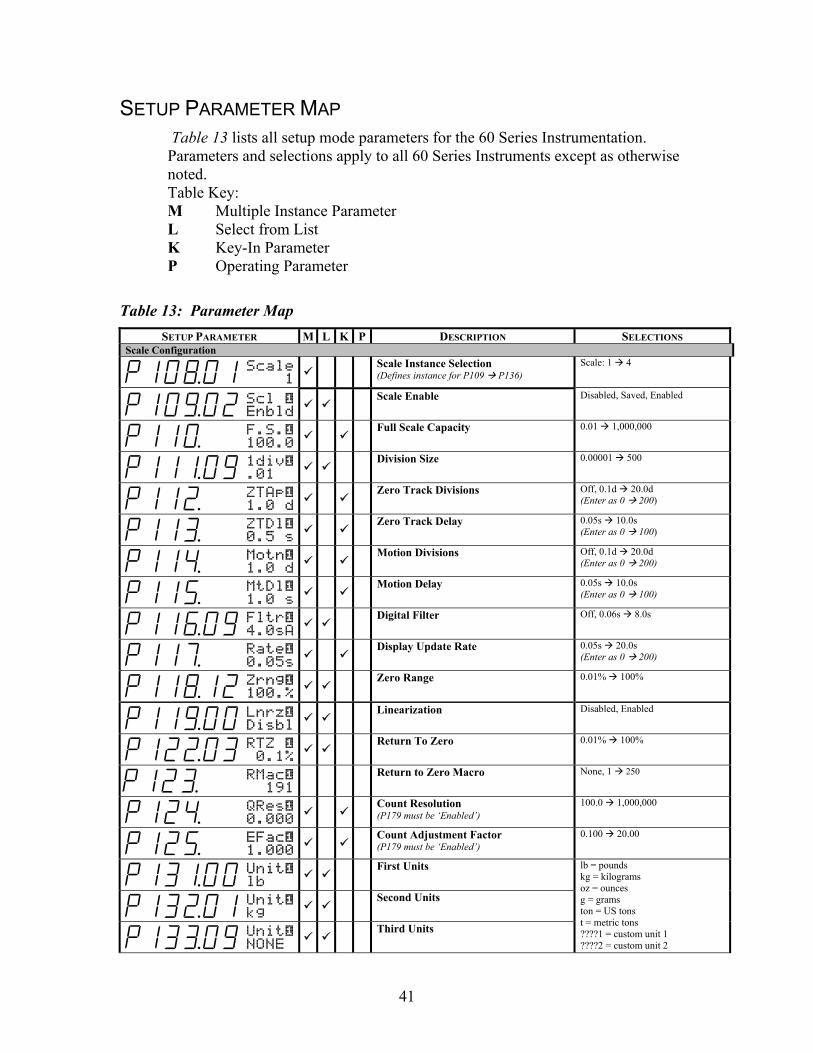
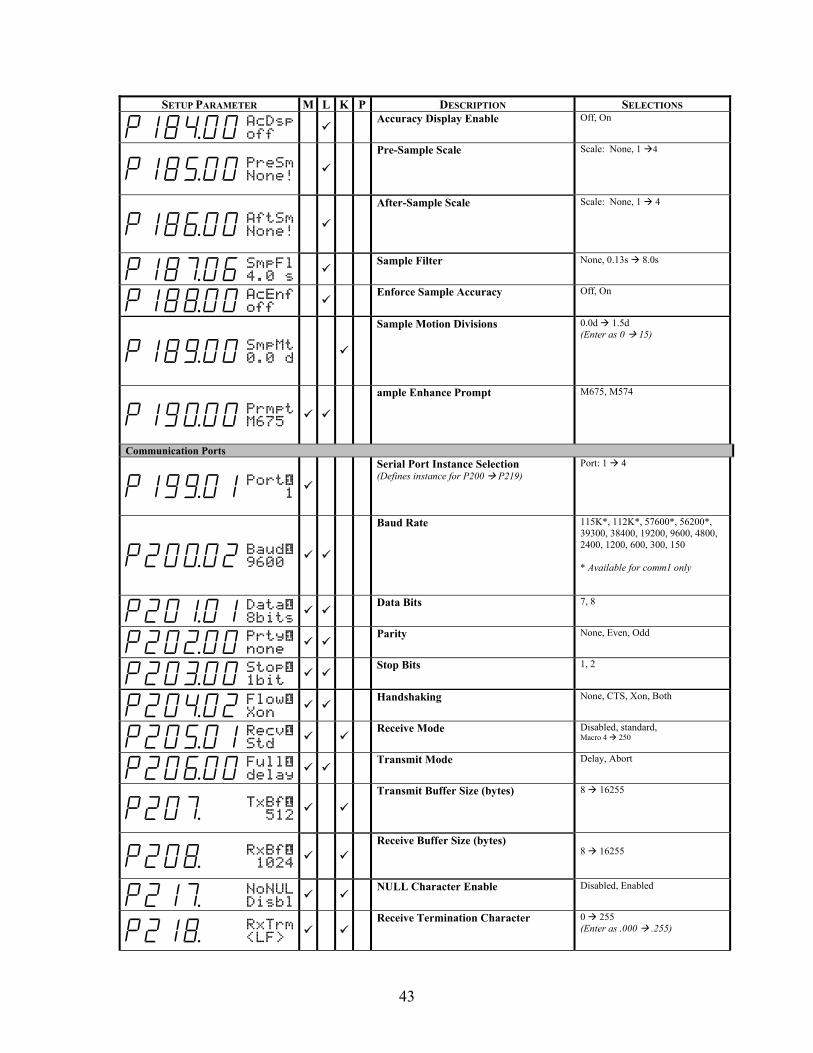
SETUP PARAMETER MAP Table 13 lists all setup mode parameters for the 60 Series Instrumentation. Parameters and selections apply to all 60 Series Instruments except as otherwise noted. Table Key: M Multiple Instance Parameter L Select from List K Key-In Parameter P Operating Parameter
Table 13: Parameter Map SETUP PARAMETER M L K P DESCRIPTION SELECTIONS
Scale Configuration
P10*01 Scale 1
Scale Instance Selection (Defines instance for P109 P136)
Scale: 1 4
P10(02 Scl — Enbld
Scale Enable Disabled, Saved, Enabled
P11)00 F.S.— 100.0
Full Scale Capacity 0.01 1,000,000
P11!09 1div— .01
Division Size 0.00001 500
P11@00 ZTAp— 1.0 d
Zero Track Divisions Off, 0.1d 20.0d
(Enter as 0 200)
P11#00 ZTDl— 0.5 s
Zero Track Delay 0.05s 10.0s
(Enter as 0 100)
P11$00 Motn— 1.0 d
Motion Divisions Off, 0.1d 20.0d
(Enter as 0 200)
P11%00 MtDl— 1.0 s
Motion Delay 0.05s 10.0s
(Enter as 0 100)
P11^09 Fltr— 4.0sA
Digital Filter Off, 0.06s 8.0s
P11&00 Rate— 0.05s
Display Update Rate 0.05s 20.0s
(Enter as 0 200)
P11*12 Zrng— 100.%
Zero Range 0.01% 100%
P11(00 Lnrz— Disbl
Linearization Disabled, Enabled
P12@03 RTZ — 0.1%
Return To Zero 0.01% 100%
P12# RMac— 191
Return to Zero Macro None, 1 250
P12$00 QRes— 0.000
Count Resolution (P179 must be ‘Enabled’)
100.0 1,000,000
P12%00 EFac— 1.000
Count Adjustment Factor (P179 must be ‘Enabled’)
0.100 20.00
P13!00 Unit— lb
First Units
P13@01 Unit— kg
Second Units
P13#09 Unit— NONE
Third Units
lb = pounds kg = kilograms oz = ounces g = grams ton = US tons t = metric tons ????1 = custom unit 1 ????2 = custom unit 2

42
SETUP PARAMETER M L K P DESCRIPTION SELECTIONS
P13$09 Unit— NONE
Fourth Units
lb oz = pounds & ounces NONE = disable units 2, 3, 4
P15)00 UNITS =lb
Default Units Same as P131 P134
P15!00 Unam1 ????1
Custom Unit1 Name Name Entry
(5 characters maximum)
P15@00 Ucon1 1.000
Custom Unit1 Conversion Factor 0.000001 9,999,999
P15#00 Unam2 ????2
Custom Unit2 Name Name Entry
(5 characters maximum)
P15$00 Ucon2 1.000
Custom Unit2 Conversion Factor 0.000001 9,999,999
Tare Functions
P16@00 TrNEG Disbl
Negative Tare Enable Disabled, Enabled
P16#01 TrRND Enbld
Tare Rounding Enable Disabled, Enabled
P16$01 NZtrkEnbld
Net Zero Tracking
Disabled, Enabled
P17)01 AnOut 1
Analog Output Instance Selection (Defines instance for P171 P176)
Analog Output: 1 4
Analog Output (P171 must be enabled to access P172 P176)
P17!00 AOut— Disbl
Analog Output Enable Disabled, Enabled
P17@00 Parm— Gross
Output Parameter
P17#99 F.S.— None!
Full Scale Output
P17$99 Zero— None!
Zero Offset
P17%99 Rnge— None!
Output Signal Range
Valid Operating Parameter
P17^00 Dflt— Max
Default Output in Setup Mode
Maximum, Minimum, Same
P17&00 Type— 0-10v
Output Signal Type
0-10VDC, 0-20mA, 4-20mA
Counting (P179 must be enabled to access P180 P189)
P17(01 CountEnbld
Count Enable Disabled, Enabled
P18)00 ASmpl off
Auto Sample Enable
Off, On
P18!01 AEnhn on
Auto Enhance Enable
Off, On
P18@10 SmpSz 10
Default Sample Size
1 9999
P18#00 %Accy 98.52
Required Accuracy
0, 90% 99.96%
43
SETUP PARAMETER M L K P DESCRIPTION SELECTIONS
P18$00 AcDsp off
Accuracy Display Enable
Off, On
P18%00 PreSm None!
Pre-Sample Scale
Scale: None, 1 4
P18^00 AftSm None!
After-Sample Scale
Scale: None, 1 4
P18&06 SmpFl 4.0 s
Sample Filter
None, 0.13s 8.0s
P18*00 AcEnf off
Enforce Sample Accuracy
Off, On
P18(00 SmpMt 0.0 d
Sample Motion Divisions
0.0d 1.5d (Enter as 0 15)
P19)00 Prmpt M675
ample Enhance Prompt M675, M574
Communication Ports
P19(01 Port— 1
Serial Port Instance Selection (Defines instance for P200 P219)
Port: 1 4
P20)02 Baud— 9600
Baud Rate 115K*, 112K*, 57600*, 56200*, 39300, 38400, 19200, 9600, 4800, 2400, 1200, 600, 300, 150 * Available for comm1 only
P20!01 Data— 8bits
Data Bits 7, 8
P20@00 Prty— none
Parity None, Even, Odd
P20#00 Stop— 1bit
Stop Bits 1, 2
P20$02 Flow— Xon
Handshaking None, CTS, Xon, Both
P20%01 Recv— Std
Receive Mode Disabled, standard,
Macro 4 250
P20^00 Full— delay
Transmit Mode Delay, Abort
P20&00 TxBf— 512
Transmit Buffer Size (bytes) 8 16255
P20*00 RxBf— 1024
Receive Buffer Size (bytes)
8 16255
P21&00 NoNUL Disbl
NULL Character Enable Disabled, Enabled
P21*00 RxTrm <LF>
Receive Termination Character
0 255 (Enter as .000 .255)
44
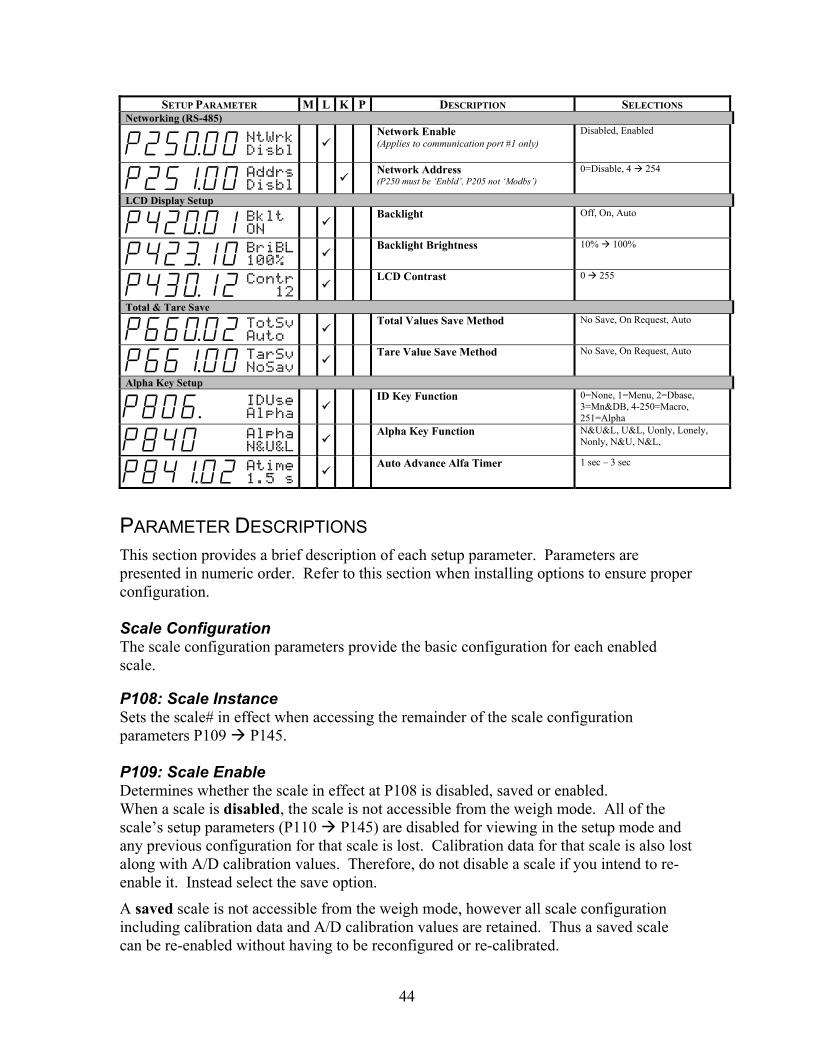
SETUP PARAMETER M L K P DESCRIPTION SELECTIONS Networking (RS-485)
P25)00 NtWrk Disbl
Network Enable (Applies to communication port #1 only)
Disabled, Enabled
P25!00 Addrs Disbl
Network Address (P250 must be ‘Enbld’, P205 not ‘Modbs’)
0=Disable, 4 254
LCD Display Setup
P42)01 Bklt ON
Backlight Off, On, Auto
P42#10 BriBL 100%
Backlight Brightness
10% 100%
P43)12 Contr 12
LCD Contrast
0 255
Total & Tare Save
P66)02 TotSv Auto
Total Values Save Method No Save, On Request, Auto
P66!00 TarSv NoSav
Tare Value Save Method No Save, On Request, Auto
Alpha Key Setup
P806. IDUse Alpha
ID Key Function 0=None, 1=Menu, 2=Dbase,
3=Mn&DB, 4-250=Macro, 251=Alpha
P840 Alpha N&U&L
Alpha Key Function N&U&L, U&L, Uonly, Lonely,
Nonly, N&U, N&L,
P84!02 Atime 1.5 s
Auto Advance Alfa Timer 1 sec – 3 sec
PARAMETER DESCRIPTIONS This section provides a brief description of each setup parameter. Parameters are presented in numeric order. Refer to this section when installing options to ensure proper configuration. Scale Configuration The scale configuration parameters provide the basic configuration for each enabled scale. P108: Scale Instance Sets the scale# in effect when accessing the remainder of the scale configuration parameters P109 P145. P109: Scale Enable Determines whether the scale in effect at P108 is disabled, saved or enabled. When a scale is disabled, the scale is not accessible from the weigh mode. All of the scale’s setup parameters (P110 P145) are disabled for viewing in the setup mode and any previous configuration for that scale is lost. Calibration data for that scale is also lost along with A/D calibration values. Therefore, do not disable a scale if you intend to re-enable it. Instead select the save option.
A saved scale is not accessible from the weigh mode, however all scale configuration including calibration data and A/D calibration values are retained. Thus a saved scale can be re-enabled without having to be reconfigured or re-calibrated.

45
An enabled scale is a fully active scale accessible from the weigh mode for viewing via the key. All weight-based operating parameters for the enabled scale will be considered valid instances when using them in macros or when assigning operating parameters to setup parameters.
P110: Full Scale Capacity Sets the scale’s full scale capacity. The capacity is entered in terms of the default units specified at P150. Capacity entries of 100,000 or greater will be displayed with the ‘kilo’ abbreviation (i.e. 100K).
An overload condition is considered to be 104% of full scale.
P111: Division Size Selects the scale’s division size. Pressing will automatically select the nearest division size less than or equal to 10,000 based on the capacity selected at P110. P112: Zero Track Divisions Selects the number of zero tracking divisions to a resolution of 0.1 divisions. For example, an entry of 35 will be accepted as ±3.5 divisions of zero tracking. If the live weight on the scale remains within the zero tracking range for a period of time specified by the zero track delay (P113), then the weight is tracked to center-of-zero. Note that when the weight on the scale falls within the zero tracking range, the weight is not displayed providing a visual indication that zero tracking is in effect. P113: Zero Track Delay Selects the zero track time delay to a resolution of 0.1 seconds. For example, an entry of 15 will be accepted as 1.5 seconds. P114: Motion Divisions Selects the number of motion divisions to a resolution of 0.1 divisions. For example, an entry of 35 will be accepted as ±3.5 divisions of motion. If the live weight on the scale remains within the motion range for a period of time specified by the motion delay (P115), then the weight is considered to be stable. Note that when the weight on the scale is considered to be in motion, the units will be not visible on the display. The units will be displayed once the scale becomes stable. P115: Motion Delay Selects the motion time delay to a resolution of 0.1 seconds. For example, an entry of 25 will be accepted as 2.5 seconds. P116: Digital Filter Selects the degree of A/D filtering used in calculating weight-based parameters. The longer the filter duration, the more stable the weight will appear. However, increasing the filter duration will also result in a slower response to rapidly changing weights and may therefore be undesirable in applications that require a prompt and accurate response to weight fluctuations. Auto-filter selections (identified as ‘sA’) can be used in such

46
situations to provide a stable reading (heavy filter) when weight changes are small and switch to a light filter when the rate of change in weight increases. P117: Display Update Rate Selects the display update time delay to a resolution of 0.1 seconds. For example, an entry of 5 will be accepted as 0.5 seconds. The display update rate does not provide any filtering effects. It can be thought of as a shutter, controlling how often the display is updated to view the current weight value. P118: Zero Range Selects the amount of weight as a percentage of full scale that can be zeroed out using the [ZERO] key. P119: Linearization Enables the five-point linearization feature used during load cell calibration. P122: Return-to-Zero Selects a weight threshold as a percentage of full scale below which the gross weight must fall before another accumulation can be performed. P123: Return-to-Zero Macro If you want to run a macro after an accumulation and the return to zero condition is met, enter the macro number at this parameter. P124: Count Resolution Selects the internal count resolution used in determining the quantity. Normally this is set to zero (0) which uses the maximum internal resolution when determining the quantity. However, when displaying a very large count of very light pieces, the display may appear unstable. Decreasing the count resolution will increase the count division size, thus making the count appear more stable. P125: Count Adjustment Factor Assigns a conversion factor to the number of additional pieces that can be added and still ensure the required accuracy is met. For example, if the adjustment factor is 1.0 and the display reports you can add up to 200 additional pieces after performing a sample, changing the adjustment factor to 0.1 would allow you to add up to 2000 pieces – changing the adjustment factor to 10.0 would only allow you to add up to 20 pieces. P131 – P134: Units Assigns the units selectable via the key from the weigh mode. The units assigned at P131 will become the power-up units for the scale presently specified at P108. Three additional units can be assigned at P132 P134 for access via the key.
The units parameters are used to assign the default units of measure and provide custom unit configuration.

47
P150: Default Units Selects the scale’s default units of measure. All weight-based parameter values are stored in terms the default units. P151 – P154: Custom Units Configures up to two (2) custom units of measure. P151 and P153 are used to assign the name for custom unit 1 and custom unit 2 respectively. P152 and P154 are the conversion factors for custom unit 1 and custom unit 2 respectively. The conversion factor is a conversion from the default units specified at P150. Tare Functions The tare functions are used to enable the negative tare and tare rounding features. P162: Negative Tare Enables the entry and use of negative tare values. P163: Tare Rounding Enables tare rounding. When enabled, the tare value is stored internally to the display resolution. This is done to ensure that the addition of multiple tare and net values will yield the correct sum when compared to the displayed values. When disabled, the tare value is stored to a higher precision and may result in a discrepancy between the accumulation of tare and net values as compared to the displayed values. P164: Net Zero Tracking Enables zero tracking in the net mode. If the net weight is withing the zero track range, it will be tracked to zero. Analog Output The analog output parameters provide configuration of the analog output modules. P170: Analog Output Instance Sets the analog output# in effect when accessing the remainder of the analog output configuration parameters P171 P177. P171: Analog Output Enable Enables the analog output currently specified at P170. P172: Output Parameter Assigns the operating parameter that the analog output will track. P173: Full Scale Output Assigns the full scale analog output. If set to “None!” the full scale capacity assigned at P110 is assumed. To specify a different full scale value, assign a variable to P173. Then, assign the desired full scale value to the assigned variable. It is advisable to configure the variable for auto-save at P684 to ensure the value is retained during power loss.

48
P174: Zero Offset Assigns the zero offset for the analog output. If set to “None!” the full zero offset is assumed to be zero (0). To specify a different zero offset value, assign a variable to P174. Then, assign the desired zero offset value to the assigned variable. It is advisable to configure the variable for auto-save at P684 to ensure the value is retained during power loss. P175: Output Signal Range Assigns the signal range for the analog output. If set to “None!” the signal range is assumed to be the maximum allowable output (10V or 20mA). To specify a different signal range value, assign a variable to P175. Then, assign the desired signal range value to the assigned variable. It is advisable to configure the variable for auto-save at P684 to ensure the value is retained during power loss.
If the output signal range is specified to be 5 for a 0-10VDC output, then the maximum output will be linearized between 0 VDC (with no zero offset) and 5 VDC at full scale. If the output signal range is specified to be 16 for a 4-20mA output, then the maximum output will be linearized between 4mA (with no zero offset) and 16mA at full scale.
P176: Default Output in Setup Mode Selects the analog output signal level when entering the setup mode. When you enter the setup mode, the A/D conversion process and all weight calculations are suspended. Thus the analog output can no longer track the value of a weight-based parameter. Select Max to generate the maximum analog output signal while in the setup mode (10V or 20mA). Select Min to generate the minimum analog output signal while in the setup mode (0V or 0mA or 4mA). Select Same to keep the analog output at the same level it was at immediately prior to entering the setup mode. P177: Output Signal Type Selects the analog output signal type (0-10VDC, 0-20mA or 4-20mA). Counting The counting parameters provide configuration of the counting feature. P179: Count Enable Enables the counting feature and makes P124, P125 and P180 P189 available for configuration. It also makes all of the counting operating parameters available as valid parameter selections. P180: Auto Sample Enable Enables the auto sample feature. When the auto sample feature is in effect, a quantity will be automatically calculated upon stability after adding the sample. P181: Auto Enhance Enable Enables the auto enhance feature. When the auto enhance feature is in effect, adding additional pieces will result in a recalculation of the APW upon stability, providing the

49
number of pieces added did not exceed the accuracy requirement. The APW is continually enhanced based on a larger sample size without the need for counting additional pieces. P182: Default Sample Size Sets the default sample size. P183: Required Accuracy Selects the accuracy requirement for sampling and auto enhancement. P184: Accuracy Display Enable Enables the accuracy display. When enabled, the calculated accuracy of the current sample will be shown on the display. P185: Pre-Sample Scale Selects the scale# to be automatically selected every time a sample routine is initiated. P186: After-Sample Scale Selects the scale# to be automatically selected after a sample routine is completed. P187: Sample Filter Selects the filter setting to be used when performing a sample operation (separate from P116). P188: Enforce Sample Accuracy Enables sample accuracy enforcement. If the required accuracy specified at P183 is not achieved during a sample routine, the sample will not be accepted. More pieces will be required to complete the sample routine. P189: Sample Motion Divisions Selects the number of motion divisions to be used during a sampling routine (separate from P111) to a resolution of 0.1 divisions. For example, an entry of 15 will be accepted as ±1.5 divisions of motion. P190: Counting Enhance Prompt Determines how the enhance prompt is displayed.
• M574 – AddUp to XXX and TakeUp to XXX • M675 – Add 1 to XXX and Take 1 to XXX
Communication Ports
The communication port parameters provide comm port configuration.
P199: Serial Port Instance Sets the communication port# in effect when accessing the remainder of the serial port configuration parameters P200 P211.

50
P200 – P204: Protocol Selects the comm port’s communication protocol. The port’s protocol must match that of the connected device. P205: Receive Mode Selects the comm port’s receive mode.
If the port is disabled, all received data is ignored
If the port is set to standard receive, all receive characters are processed normally.
If the port is set to interpret, all received characters are screened through the input interpreter (P217 P224) before being used or discarded.
If the port is set for Modbus, all received characters are processed as Modbus protocol. Enabling Modbus at P205 makes P209 P211 available for configuration. If the port is set for selection 4 250, a received character will invoke macro 4 250 respectively. P206: Transmit Mode Selects whether or not a transmission will be delayed when the transmit buffer becomes full.
If set to delay, the transmission will be put on hold until the transmit buffer empties to the point where handshaking is asserted.
If set to abort, the transmission will be immediately aborted once the transmit buffer becomes full. This is not true while downloading the setup mode at P64000-64001. The download will continue uninterrupted.
P207 – P208: Transit / Receive Buffer Size Sets the size of the transmit and receive buffers at P207 and P208 respectively. P209: Modbus Address Selects the Modbus address. P205 must be set for Modbus for this parameter to be available. P210: Modbus Mode Selects Modbus ASCII or RTU mode. P205 must be set for Modbus for this parameter to be available. Networking (RS-485) The networking parameters configure an indicator’s network address. Remote communication parameters configure communication to a remote display, other indicators used in the remote display mode and other devices requesting display information.

51
P250: RS-485 Enable This parameter only affects comm port 1. It enables RS-485. Enabling this parameter detrimental effect on RS-232 operation. Enabling this parameter changes how data is transmitted see the %q macro and RS-485 sections for more details. P251: RS-485 Network Address This parameter assigns the RS-485 network address for the indicator (COMM1 only). It has no effect if set to address zero (0). This parameter has no effect if DeviceNet or ModBus are enabled at P205. When an address is specified, the indicator will only respond to messages that begin with an <STX> followed by this address value. Subsequent data is processed by the indicator until an <ETX> is received completing the data packet.
<STX><ADDRESS><DATA><ETX>
Note that the network address is assigned as a single byte value. An entry of ‘4’ refers to an <EOT> control code. If you want the indicator’s address to be the number four (4), you would have to enter the address as 52 (the ASCII value of 4).
LCD Display Setup
The LCD display setup parameters define the operation of the standard displays.
P420: Standard VF Display Mode Controls the backlighting of the LCD. P423 Display Brightness Selects the degree of VFD brightness when the display is on (P423) and off (P424). P430: LCD Contrast Selects the power-up contrast setting for the LCD display. Pressing will restore the default contrast setting.
The LCD contrast can also be set at power-up without accessing the setup mode.
Total & Tare Save
The total & tare save parameters are used to enable the tare and accumulation parameter values to be saved in non-volatile memory and restored in the even of power loss.
P660 – P661: Total / Tare Save Method Selects whether accumulation values and tare values will be written to the EEPROM each time the values change so that the values may be retained and restored in the event of a power loss.
If set to AUTO, the values are automatically stored to the EEPROM when changed.
If set to No Save, the values are not written to the EEPROM and will be lost during a power failure.
52
If set to On Request, the values can only be written to the EEPROM via the %v macro command. P806, P840 and P841: Alpha Key Function The Alpha key is a new key added on the Model 675 only.
Parameter 806 is where the Alpha key function is enabled or disabled. Set P806 to Alpha by keying in .
Parameter 840 is where the function of the Alpha key is set. There are many ways to display and enter alpha characters.
N&U&L = The alpha key will scroll the numeral then the uppercase letter and then the lower case letter displayed on the key pressed.
U & L = The alpha key will scroll the uppercase letter and then the lower case letter displayed on the key pressed.
U only = The alpha key will display the uppercase letter displayed on the key pressed.
L only = The alpha key will display the lowercase letter displayed on the key pressed.
N only = The alpha key will display the numeral displayed on the key pressed.
N & U = The alpha key will display the numeral and then the uppercase letter display on the key pressed.
N & L = The alpha key will display the numeral and then the lowercase letter display on the key pressed.
Parameter 841 defines the delay time before a character is accepted allowing a different character from the same key to be entered.
APPLICATIONS (APPS) The applications refer to the preprogrammed files that are included with the Model 675. If you choose to reload one of the application files press at the Apps tab. An access code must be entered to reinstate the application menu. The main menu will reload where you can choose the desired application.

53
CHAPTER 4: OPERATION This chapter will give detailed operation instructions on how to use each preprogrammed mode.
The Model 675 is designed to operate from the 5 soft keys or the dedicated keys of the keypad. The advantage of using the soft keys is they are placed in succession for easy operation.
Quick Count Auto Tare Method 1. Sampling Pieces:
(a) If a container is used: (i) Place an empty container on scale and press the Sample or
key. The scale will automatically tare the container. - or -
(b) If a container is not used:
(i) Press the Sample or key without the sample pieces on the scale. The scale will tare to establish a net zero reference.
2. Add the sample pieces and press the Accept key to accept the sample.
3. Continue to add pieces to count.
4. Press to accumulate the current quantity to the total quantity.
5. Press to print to a computer, printer or another peripheral device.
TIP Bypass the GSE splash screen on power up by pressing the key when the splash screen appears.

54
Without Auto Tare 1. Sampling pieces:
(a) If the sample size is known and a container is used:
(i) Place an empty container on the scale and press key.
(ii) Place the sample in the container.
(iii) Key in the sample size and then press the Sample or key. The scale will accept the current weights as a sample and will display the quantity.
-or-
(b) If the sample size is known and no container is used: (i) Place the sample on the scale.
(ii) Key in the sample size and then press the Sample or key. The scale will accept the current weights as a sample and will display the quantity.
Example: or
After accumulating, the weight must return to zero before another accumulation will be added. The display will show CLEAR WGHT! if the weight is not within the zero threshold. Remove weight and try again. This feature is necessary to avoid double accumulations.
Use the key to check other modes such as the Tare weight and Average Piece
Weight. The (Count) can be pressed to return to the count mode at any time.
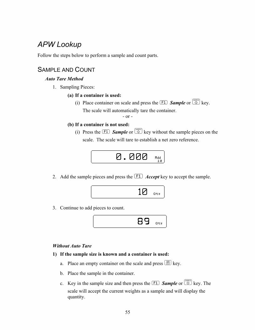
55
APW Lookup Follow the steps below to perform a sample and count parts.
SAMPLE AND COUNT Auto Tare Method
1. Sampling Pieces:
(a) If a container is used: (i) Place container on scale and press the Sample or key.
The scale will automatically tare the container. - or -
(b) If a container is not used: (i) Press the Sample or key without the sample pieces on the
scale. The scale will tare to establish a net zero reference.
2. Add the sample pieces and press the Accept key to accept the sample.
3. Continue to add pieces to count.
Without Auto Tare
1) If the sample size is known and a container is used:
a. Place an empty container on the scale and press key.
b. Place the sample in the container.
c. Key in the sample size and then press the Sample or key. The scale will accept the current weights as a sample and will display the quantity.

56
-or-
1) If the sample size is known and no container is used: a. Place the sample on the scale.
b. Key in the sample size and then press the Sample or key. The scale will accept the current weights as a sample and will display the quantity.
Example: or
STORE A NEW PART NUMBER Part numbers can be stored in a database and can be recalled later with necessary data such as the average piece weight and description.
1. Press the (Rec/New) key. The data fields will be cleared. 2. Follow the directions for sample and count above.
3. If you want to add a part description key in the description and press (Desc.). Skip this step if the description is not necessary.
4. Key in the part number and press to store the part number, APW, and description.
UPDATE A PART NUMBER It is possible to update the data that is stored with a part number.
1. While viewing the part number and data press (Store). The data will be updated in the database.
RECALL A PART NUMBER A part number that was stored previously can be recalled to count parts without having to sample the part.
1. Key in the part number to recall and press (Rec/New). 2. Place pieces on the platform to count.

57
DELETE A PART NUMBER Any part number that is stored may be deleted.
1. Recall the part number to be deleted by keying in the part number and
pressing (Rec/New). The part number does not have to be recalled if it already being viewed.
2. Press (Setup).
3. Press (Delete Part#). You will be prompted with the part number to be deleted and the choice of deleting the part number or aborting the process. This key will not appear if a part number has not been recalled.
4. Press to cancel and return to the APW LOOKUP screen or to continue deleting the part number.
Simple Keypad Sample Auto Tare Method 1. Sampling Pieces:
(a) If a container is used - Place container on scale and press the key. The scale will automatically tare the container.
- or - (b) If a container is not used - Press the key without the sample pieces
on the scale. The scale will tare to establish a net zero reference.
2. Add the sample pieces and press the key to accept the sample.
3. Continue to add pieces to count.

58
Without Auto Tare
1) If the sample size is known and a container is used:
a. Place an empty container on the scale and press key.
b. Place the sample in the container.
c. Key in the sample size and then press the key. The scale will accept the current weights as a sample and will display the quantity.
-or-
1) If the sample size is known and no container is used: a. Place the sample on the scale.
b. Key in the sample size and then press the key. The scale will accept the current weights as a sample and will display the quantity.
Example:

59
CHAPTER 5: CALIBRATION The calibration mode is accessible through the configuration menu or from the weigh mode. Access Calibration from the configuration menu
1. From the main menu press the (Setup) key.
2. Press (Setup Menus) key.
3. Press (CAL) key.
4. Enter the access code and press
Performing Calibration There are six methods of calibration. Press to select a calibration method (see example: Selecting a Calibration Method). Press to begin the calibration method selected. Refer to the appropriate section for calibration instructions.
• New Zero - Establishes a new zero (no load) and span (test load) calibration reference.
• Last Zero - Performs a span re-calibration without removing the test load. (This selection is not available with linearization enabled.)
• Temp Zero - Performs a calibration without removing the current gross weight. The zero reference determined during the last calibration is maintained. (This selection is not available with linearization enabled.)
• Only Zero - Establishes a new zero reference without affecting span.
• Cal Reset - Adjusts the zero and gain factors of the A/D amplifier to default values for maximum sensitivity.
• Known LCOut - Calibrates without the use of test weights. The mV/V value and full scale capacity of each load cell must be known.
Example: Selecting a Calibration Method
)05 New Zero?
)05 Last Zero?
)05 Temp Zero?
)05 Only Zero?
)05 Cal Reset
)05 KnownLCOut

60
GENERAL NOTES ON CALIBRATION • Pressing at any point in the calibration routine
moves back one step.
• Pressing at the New Zero? prompt exits calibration mode.
• A calibration weight can be applied before or after entering the calibration weight value. The display prompts you to Keyin CalWt (key in calibration weight) or Add CalWT (add calibration weight) at the appropriate time.
• The digital filter is automatically set to 4 seconds during calibration.
• A motion delay is enforced during zero and span calibration.
• New calibration values are not permanently saved until the calibration mode is exited and changes are saved by pressing at the ENTER=SAVE prompt. If power is lost during calibration, the previously saved calibration values will be in effect when power is restored.
• If replacing one indicator with another, it is possible to set the total gain value (P61108) of the new indicator with that of the original. This will optimize the coarse & fine gain values, greatly increasing the likelihood of a successful calibration on the first attempt.

61
NEW ZERO The most common calibration procedure, New Zero establishes a new zero (no load) and span (test load) calibration reference. Use this method for first-time calibration and complete re-calibration.
To perform a New Zero calibration:
1. Remove all weight from the scale. 2. Enter calibration as described on page 59 3. Select the New Zero calibration method as described
in Calibration Methods on page 59.
4. Press at the New Zero? prompt to establish the new zero reference.
5. After establishing the zero reference, the default calibration units are displayed momentarily followed by the Keyin CalWt prompt.
6. Apply the calibration weight, key in the calibration weight value in terms of the default calibration units and press to establish span. If the calibration weight value was entered before the weight was applied, the display will prompt Add CalWT. Add the calibration weight and press .
7. After establishing span, CAL OK? is displayed suggesting that the calibration is acceptable, or ReCal??? is displayed suggesting that the calibration procedure should be repeated.
8. Accept the calibration by pressing at the CAL
OK? prompt or at the ReCal??? prompt. - or - Repeat the calibration by pressing at the CAL
OK? prompt or at the ReCal??? prompt.
9. Once the calibration is accepted in step 6, press at the ENTER=SAVE prompt and again at the ENTER=EXIT prompt to save the new calibration and exit the calibration mode. - or - To exit the calibration mode without saving the new calibration, press at the ENTER=SAVE prompt.
Then press at the ENTER=UNDO prompt and again at the ENTER=EXIT prompt to exit the calibration mode.
If you choose to “undo” the calibration when exiting the setup mode, you will also undo any unsaved changes made to the setup parameters.
Example: New Zero Calibration
)05 New Zero?
)05 Mot’n Delay
)05 Units =lb
)00 Keyin CalWt
ADD TEST WEIGHT
10)00 Mot’n Delay
10)00 CAL OK ?
SETUP Save Mods?
SETUP ENTER =SAVE
SETUP Exit Setup
SETUP ENTER =EXIT
10)00 lb Gross

62
LAST ZERO Last Zero allows span re-calibration without removing the applied test weight. The last zero established by pressing from the weigh mode will be used as the zero reference. This procedure is especially useful when performing routine tolerance checks on large capacity scales. A scale found to be out-of-tolerance can be easily calibrated without having to remove the test weights to reestablish a zero reference.
To perform a Last Zero calibration: 1. Remove all weight from the scale.
2. Press to zero the scale in the weigh mode.
3. Apply the calibration test weight. 4. Access the calibration mode as described on page 59. 5. Select the Last Zero calibration method as described in
Calibration Methods on page59 .
6. Press at the Last Zero? prompt to display the Keyin CalWT prompt.
7. Key in the calibration weight value in terms of the default calibration units and press to establish span.
8. After establishing span, CAL OK? is displayed suggesting that the calibration is acceptable, or ReCal??? is displayed suggesting that the calibration procedure should be repeated.
Accept the calibration by pressing at the CAL
OK? prompt or at the ReCal??? prompt. - or - Repeat the calibration by pressing at the CAL
OK? prompt or at the ReCal??? prompt.
9. Once the calibration is accepted in step 6, press at the ENTER=SAVE prompt and again at the ENTER=EXIT prompt to save the new calibration and exit the calibration mode. - or - To exit the calibration mode without saving the new calibration, press at the ENTER=SAVE prompt.
Then press at the ENTER=UNDO prompt and again at the ENTER=EXIT prompt to exit the calibration mode.
If you choose to “undo” the calibration when exiting the setup mode, you will also undo any unsaved changes made to the setup parameters.
Example: Last Zero Calibration
2) lb Gross
0) lb Gross
ADD 10,000 LB TEST WEIGHT
1004) lb Gross
ACCESS CALIBRATION MODE
1004) New Zero?
1004) Last Zero?
1004) Units =lb
1004) Keyin CalWt
1000) CAL OK ?
SETUP Save Mods?
SETUP ENTER =SAVE
SETUP Exit Setup
SETUP ENTER =EXIT
1000) lb Gross

63
Example: Temporary Zero Calibration
2105) lb Gross
ACCESS CALIBRATION MODE
SETUP Quick Cal!
2105) New Zero?
2105) Temp Zero?
2105) Mot’n Delay
2105) Units =lb
0) Keyin CalWt
ADD TEST WEIGHT
201) Mot’n Delay
200) CAL OK ?
SETUP Save Mods?
SETUP ENTER =SAVE
200) lb Gross
TEMPORARY ZERO Temp Zero is used to calibrate without establishing a new zero. Calibration can be performed without removing the currently applied gross load. A temporary zero is established so that test weights can be added during calibration. The original zero reference determined during the previous calibration is not affected. This procedure is commonly used to calibrate hopper scales where it is impractical to empty the product before calibrating.
To perform a Temp Zero calibration: 1. Access the calibration mode as described on page 59. 2. Select the Temp Zero calibration method as described
in Calibration Methods on page59.
3. Press at the Temp Zero? prompt to establish a temporary zero reference.
4. After establishing the temporary zero reference, the default calibration units are displayed momentarily followed by the Keyin CalWT prompt.
5. Apply the calibration weight, key in the calibration weight value in terms of the default calibration units and press to establish span. If the calibration weight value was entered before the weight was applied, the display will prompt Add CalWT. Add the calibration weight and press .
6. After establishing span, CAL OK? is displayed suggesting that the calibration is acceptable, or ReCal??? is displayed suggesting that the calibration procedure should be repeated. Accept the calibration by pressing ] at the CAL
OK? prompt or at the ReCal??? prompt. - or - Repeat the calibration by pressing at the CAL
OK? prompt or at the ReCal??? prompt.
7. Once the calibration is accepted in step 6, press at the ENTER=SAVE prompt and again at the ENTER=EXIT prompt to save the new calibration and exit the calibration mode. - or -
To exit the calibration mode without saving the new calibration, press at the ENTER=SAVE prompt.
Then press at the ENTER=UNDO prompt and again at the ENTER=EXIT prompt to exit the calibration mode.

64
Example: Only Zero Calibration
9% lb Gross
ACCESS CALIBRATION MODE
SETUP Keyin Code:
SETUP Quick Cal!
9% Only Zero?
9% Mot’n Delay
0) CAL OK ?
SETUP Save Mods?
SETUP ENTER =SAVE
SETUP Exit Setup
SETUP ENTER =EXIT
0) lb Gross
ONLY ZERO Only Zero is used for zero calibration only. This calibration procedure is primarily used for the zero reference after changing a scale’s dead-load, such as adding safety rails to a scale deck or installing a mixer motor on a hopper scale. Because the full scale capacity is referenced from the last zero calibration, performing a zero calibration helps to ensure that the full scale over-load will not occur prematurely due to the additional dead-load.
To perform an Only Zero calibration:
1. Remove all weight from the scale. 2. Access the calibration mode as described on page 59.
Select the Only Zero calibration method as described in Calibration Methods on page 59.
3. Press at the Only Zero? prompt to establish the new zero reference.
4. After establishing zero, CAL OK? is displayed suggesting that the calibration is acceptable. Accept the calibration by pressing at the CAL OK? prompt. - or - Repeat the calibration by pressing at the CAL OK? prompt.
5. Once the calibration is accepted in step 5, press at the ENTER=SAVE prompt and again at the ENTER=EXIT prompt to save the new calibration and exit the calibration mode. - or - To exit the calibration mode without saving the new calibration, press at the ENTER=SAVE prompt.
Then press at the ENTER=UNDO prompt and again at the ENTER=EXIT prompt to exit the calibration mode.
If you choose to “undo” the calibration when exiting the setup mode, you will also undo any unsaved changes made to the setup parameters.

65
CALIBRATION RESET Cal Reset sets the gain factors of the A/D amplifier to minimum values and clears the A/D’s zero offset. These gain values are stored in the Information Parameters at P61104 P61107 (see the Calibration Parameters section). A Cal Reset should be performed if calibration is not possible due to an over-load condition, or if the displayed weight value does not change when the test weight is applied.
To perform a Calibration Reset:
1. Access the calibration mode as described on page 59.
2. Select the Cal Reset calibration method as described in Calibration Methods on page 59.
3. Press at the Cal Reset prompt reset the A/D amplifier.
4. The display prompts New Zero?. Proceed with calibration.
KNOWN LOADCELL OUTPUT Known LCOut is used to calibrate without test weights. The exact full scale mV/V rating must be known for each load cell. All load cells must be of the same full scale capacity. This procedure works best for hopper scales where weight is evenly distributed and signal trimming is not required.
To perform a Known Loadcell Output calibration:
1. Access the calibration mode as described on page 59.
2. Select the Known LCOut calibration method as described in Calibration Methods on page 59.
3. Press at the Known LCOut prompt to display #of LC.
The number of load cells specified during the last calibration will also be displayed. A value of zero (0) indicates that this calibration method has not yet been performed.
4. Key in the number of load cells (8 maximum) and press . - or -
If an over-load condition exists at
the time of calibration, the calibration method prompts are replaced by an Over load! message. Press [CLR] to proceed directly to the Cal Reset procedure.
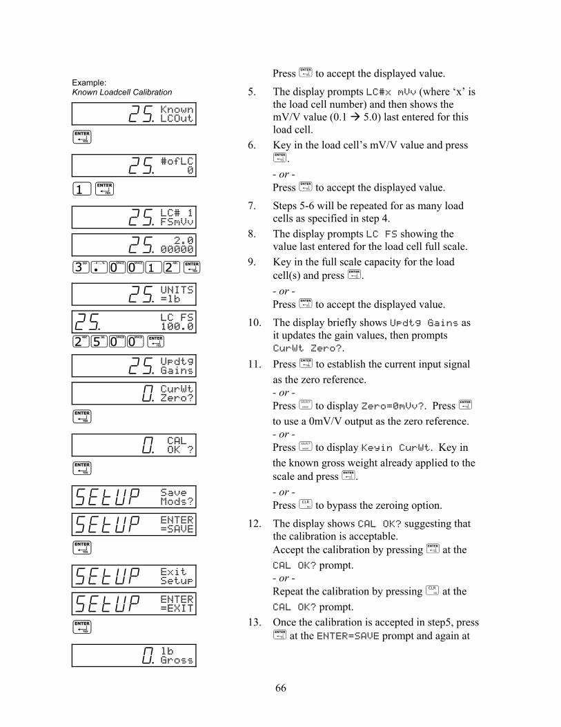
66
Press to accept the displayed value.
5. The display prompts LC#x mVv (where ‘x’ is the load cell number) and then shows the mV/V value (0.1 5.0) last entered for this load cell.
6. Key in the load cell’s mV/V value and press .
- or - Press to accept the displayed value.
7. Steps 5-6 will be repeated for as many load cells as specified in step 4.
8. The display prompts LC FS showing the value last entered for the load cell full scale.
9. Key in the full scale capacity for the load cell(s) and press . - or - Press to accept the displayed value.
10. The display briefly shows Updtg Gains as it updates the gain values, then prompts CurWt Zero?.
11. Press to establish the current input signal as the zero reference. - or - Press to display Zero=0mVv?. Press to use a 0mV/V output as the zero reference. - or - Press to display Keyin CurWt. Key in the known gross weight already applied to the scale and press . - or - Press to bypass the zeroing option.
12. The display shows CAL OK? suggesting that the calibration is acceptable. Accept the calibration by pressing at the CAL OK? prompt. - or - Repeat the calibration by pressing at the CAL OK? prompt.
13. Once the calibration is accepted in step5, press at the ENTER=SAVE prompt and again at
Example: Known Loadcell Calibration
2% Known LCOut
2% #ofLC 0
2% LC# 1 FSmVv
2% 2.0 00000
2% UNITS=lb
2% LC FS 100.0
2% Updtg Gains
) CurWtZero?
) CAL OK ?
SETUP Save Mods?
SETUP ENTER =SAVE
SETUP Exit Setup
SETUP ENTER =EXIT
) lb Gross
67
the ENTER=EXIT prompt to save the new calibration and exit the calibration mode. - or -
To exit the calibration mode without saving the new calibration, press at the ENTER=SAVE prompt. Then press at the ENTER=UNDO prompt and again at the ENTER=EXIT prompt to exit the calibration mode.
Multi - Scale Calibration When more than one scale is enabled, the prompt Keyin Scl# appears before accessing the calibration method selections. Key in the scale number to be calibrated and press
. Proceed with a calibration method as described in Calibration Methods on page 59. After completing a calibration, the Keyin Scl# appears once again. Enter the next scale number to be calibrated, or press to exit the calibration mode and save the new calibration data.
Calibration Units It is expected that a calibration weight will be entered in terms of the selected calibration units as determined by P150 in the setup mode. The default calibration units are displayed briefly during calibration just prior to the Keyin CalWT prompt. Alternate units may be used during calibration by pressing the key at the Keyin CalWT prompt. This will scroll through any units that have been assigned to P131 P134 of the setup mode for the selected scale.
It is not possible to select lb/oz as
calibration units.

68
MULTI - POINT LINEARIZATION Multi-point linearization provides up to five calibration points for each scale input. This allows you to compensate for load cell non-linearity. Multi-point linearization must be enabled in the setup mode at P119. Once enabled, you can define up to five points of linearization in during the calibration routine.
To perform Multi-Point Linearization:
1. Access the calibration mode as described on 2. page 59. 3. Select a calibration method as described in
Calibration Methods on page 59 and proceed with the calibration routine.
4. Enter the calibration weight value for the first linearization point when prompted to Keyin CalWT.
5. Once the first linearization point is established, Keyin Pnt2 is displayed. If there was a significant change in span for the first linearization point, ReCal??? is displayed suggesting that the calibration procedure must be repeated for the first point.
6. Enter the calibration weight value for the second linearization point.
7. Repeat this process for up to five linearization points. If fewer than five linearization points are specified, press without keying in the next weight value to end calibration.
8. After establishing all linearization points, CAL OK? is displayed suggesting that the calibration is acceptable. Press at the CAL OK? prompt to accept the calibration and exit. - or - Press at the CAL OK? prompt to repeat the calibration.
Linearization calibration weights
and calibration factors can be viewed at P61130 P61139 in the information parameters.
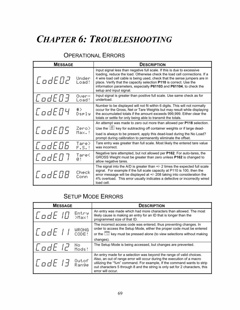
69
CHAPTER 6: TROUBLESHOOTING OPERATIONAL ERRORS
MESSAGE DESCRIPTION
Code02 UnderLoad!
Input signal less than negative full scale. If this is due to excessive loading, reduce the load. Otherwise check the load cell connections. If a 4 wire load cell cable is being used, check that the sense jumpers are in place. Verify that the capacity selection P110 is correct. Use the information parameters, especially P61103 and P61104, to check the setup and input signal.
CoDE03 Over-Load!
Input signal is greater than positive full scale. Use same check as for underload.
CoDE04 #>
Dsply
Number to be displayed will not fit within 6 digits. This will not normally occur for the Gross, Net or Tare Weights but may result while displaying the accumulated totals if the amount exceeds 999,999. Either clear the totals or settle for only being able to transmit the totals.
CoDE05 Zero>
Max.!
An attempt was made to zero out more than allowed per P118 selection. Use the key for subtracting off container weights or if large dead-load is always to be present, apply this dead-load during the No Load? prompt during calibration to permanently eliminate the offset.
CoDE06 Tare>
F.S.! Tare entry was greater than full scale. Most likely the entered tare value was incorrect.
CoDE07 Tare<
0!
Negative tare attempted, but not allowed per P162. For auto-tares, the GROSS Weight must be greater than zero unless P162 is changed to allow negative tares.
CoDE08 Check
Conn
The signal into the A/D is greater than +/- 2 times the expected full scale signal. For example if the full scale capacity at P110 is 100, then the error message will be displayed at +/- 208 taking into consideration the 4% overload. This error usually indicates a defective or incorrectly wired load cell.
SETUP MODE ERRORS MESSAGE DESCRIPTION
CoDE10 Entry
>Max!
An entry was made which had more characters than allowed. The most likely cause is making an entry for an ID that is longer than the programmed size of that ID.
CoDE11 WRONG
CODE!
The incorrect access code was entered, thus preventing changes. In order to access the Setup Mode, either the proper code must be entered or the key must be pressed alone (to view selections without making changes).
CoDE12 No
Mods! The Setup Mode is being accessed, but changes are prevented.
CoDE13 Outof
Range
An entry made for a selection was beyond the range of valid choices. Also, an out of range error will occur during the execution of a macro utilizing the “%m” command. For example, If the command wants to strip out characters 5 through 8 and the string is only set for 2 characters, this error will occur.

70
MESSAGE DESCRIPTION
CoDE14 Must
Keyin The choice for the current parameter must be keyed in.
CoDE15 Size
>Max!
The size of one of the input interpreter, macro or custom transmit tables has exceeded it’s limit. Input interpreter size is limited to 198 for 660 Series, 98 for all other products; macro size is limited to 9996; custom transmit size is limited to 3997.
CoDE16 CHECK
JUMPR
A programming operation was attempted when the program jumper is installed. Installation of this jumper will prohibit any programming changes.
HARDWARE ERRORS MESSAGE DESCRIPTION
No
Macro
An attempt was made to abort a macro when no macros were defined.
Macro
error An error occurred during macro execution. Check for proper syntax. Analyze the macro debug buffer to help determine the cause of the error.
No
Start
A serial or A/D database collection command (%’ or %*) was executed prior to the “start collection” command.
Must Free
A serial or database start collection command (S%’ or S%*) was issued without first freeing memory with the F%’ or F%* command.
Wrongparm
The parameter specified for data collection using the %* command was invalid or not of type float.
CoDE81 Macro
Stack
The maximum number of macros pushed onto the stack has been exceeded. This error usually indicates that macros are being invoked faster than they can be executed (for example, macros invoked by continuous, short-interval input setpoints, multiple macro “calls”, etc.) The maximum number of macros on the stack is 200.
CoDE82 Macro
Abort A macro was aborted from within a macro via one of the macro abort operations or from the front keypad by pressing +
CoDE83 Macro
UnDef A call or similar reference to an undefined macro occurred. Make sure the intended macro is configured beginning at P9990.
CoDE84 Math
error
An incorrect math operation has been performed. This could be caused by trying to divide by zero or any other non-acceptable algebraic operation. This message will also occur if trying to take the negative or zero modulus of a number.
CoDE85 Syntx
Error
An error occurred during macro execution as the result of invalid syntax. Re-check the macro or analyze the macro debug table to find out where the error occurred. Refer to Chapter 9 for proper macro syntax.
CoDE86 Macro Brace
The number of opening and closing braces within a macro are different. When nesting conditional statements or grouping conditional Boolean statements, make sure the proper use the % and % brace commands.
CoDE87 NoTag Found
An attempt was made to jump to an undefined tag. When using simple jump-tag commands, make sure the intended tag is properly specified and that the tag command is executed before the jump. When using macro-independent jump-tag commands, make sure the correct macro number is specified and that the jump text matches that of the tag.

71
CALIBRATION ERRORS MESSAGE DESCRIPTION
Code92 „Stpt
Setup
A parameter entry is required for a setpoint’s Activation Limit, Deactivation Limit, or Compare parameter. Pressing any key will automatically select the offending parameter and allow you to correct it.
CoDE95 SyErrNvRam
The EEPROM size is too small to allocate the database requested.
CoDE95 SyErrHSR00
An error occurred at startup or during operation. Contact GSE.
CoDE95 SyErrTyp04
An error occurred at startup. Contact GSE.
Code96 EraseBoot!
An attempt was made to enter an instrument serial number or board serial number with the flash already programmed.
CoDE99 Can't
Set!
An attempt to enter a value for a parameter which is not field changeable, such as the serial numbers or the audit trail counter results in this message.
P___ InvldMode!
An attempt was made to access a non-existent parameter. Key in a valid parameter and press , or press only or to proceed to the nearest lower valid parameter.
Mode <100!
An attempt was made to access a weigh mode parameter from within the setup mode. Valid setup mode parameters contain three or more digits.
Press Enter
The key was pressed at a “pick instance” prompt. You must press
to select an instance, or to abort the instance entry.
Okay?#####
This is not an error. Press to acknowledge your entry, or to re-enter.
Cksum
error
Upon each power-up, the indicator tests the integrity of its firmware. If the result is not correct this message is displayed and the indicator is not usable. ReFlash the indicator.
MdBus Max!
An attempt was made to modify the modbus parameter map past its limit of P6999.
COMMUNICATION ERRORS MESSAGE DESCRIPTION
prtyX
error
The parity of a received character did not match the parity specified in the setup mode at P202. This could also result if the baud rate (P200) or the number of data bits (P201) are incorrect. The ‘X’ in the error message represents the COMM port number on which the problem occurred.
ovrnX
error
An overrun error occurred where additional characters were received while the receive buffer was full. The additional characters will be lost. The ‘X’ in the error message represents the COMM port number on which the problem occurred.
frmgX
error
The stop bit of a received character did not occur when it was expected. This could be the result of an incorrect baud rate (P200), incorrect number of data bits (P201), or incorrect parity setting (P202). The ‘X’ in the error message represents the COMM port number on which the problem occurred.

72
MESSAGE DESCRIPTION
portX
error
The indicator did not check its receive data register in time, thus missing a character. To prevent the problem, try reducing the baud rate (P200). The ‘X’ in the error message represents the COMM port number on which the problem occurred.
NoTxX
Allow
Associated with Modbus. This is selected at P205. This message indicates that a transmission out the specified port was attempted. This is not acceptable if the port is set for Modbus. The ‘X’ in the error message represents the COMM port number on which the problem occurred.
tx on
hold
Occurs if a data transmission is held up for two seconds of more due to a deasserted handshake. Refer to the description of parameter P209 for more information.
tx
abort
Occurs if the key is pressed when the tx on hold error message is shown or if P209 is set for abort and the transmit buffer becomes full.
tx
Con'd Appear briefly when the handshake is re-asserted after the tx on hold message occurs.
BadTx
Port Appears briefly after an attempt was made to put a byte in an invalid comm port receive buffer.
Wrong
Comm#
An invalid communication port number was specified.


Part Number 39-10-41435