guide cylinder series mgg - smc etechcontent.smcetech.com/pdf/mggm_2111x.pdf · ball bushing...
TRANSCRIPT
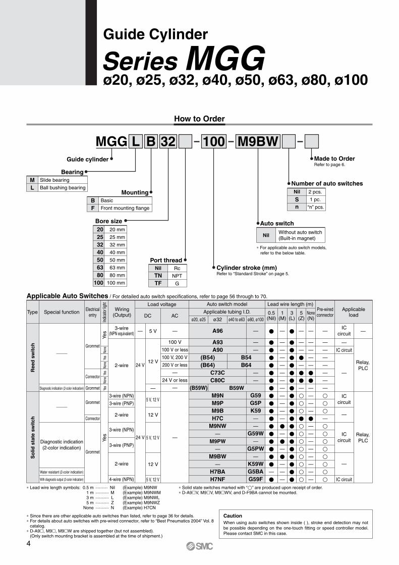
L M9BWB 32Guide cylinder
MGG 100
Number of auto switches
Made to OrderRefer to page 6.
Nil
Sn
2 pcs.
1 pc.
“n” pcs.
Auto switch
∗ For applicable auto switch models, refer to the below table.
NilWithout auto switch(Built-in magnet)
Cylinder stroke (mm)Refer to “Standard Stroke” on page 5.
Port threadRc
NPT
G
Nil
TNTF
Bore size20253240506380
100
20 mm
25 mm
32 mm
40 mm
50 mm
63 mm
80 mm
100 mm
MountingBF
Basic
Front mounting flange
BearingML
Slide bearing
Ball bushing bearing
4
How to Order
Guide Cylinder
ø20, ø25, ø32, ø40, ø50, ø63, ø80, ø100Series MGG
Applicable Auto Switches / For detailed auto switch specifications, refer to page 56 through to 70.
∗ Lead wire length symbols: 0.5 m ·········· Nil (Example) M9NW 1 m ··········· M (Example) M9NWM 3 m ··········· L (Example) M9NWL 5 m ··········· Z (Example) M9NWZ None ··········· N (Example) H7CN
∗ Solid state switches marked with “�” are produced upon receipt of order.∗ D-A9�V, M9�V, M9�WV, and D-F9BA cannot be mounted.
∗ Since there are other applicable auto switches than listed, refer to page 36 for details.∗ For details about auto switches with pre-wired connector, refer to “Best Pneumatics 2004” Vol. 8
catalog.∗ D-A9�, M9�, M9�W are shipped together (but not assembled).
(Only switch mounting bracket is assembled at the time of shipment.)
When using auto switches shown inside ( ), stroke end detection may not be possible depending on the one-touch fitting or speed controller model. Please contact SMC in this case.
Caution
Type Special function Electricalentry
Grommet
Grommet
Grommet
Connector
Connector
Grommet
100 V
100 V or less
100 V, 200 V
200 V or less
—
24 V or less
—
Wiring(Output)
3-wire(NPN equivalent)
2-wire
3-wire (NPN)
3-wire (PNP)
2-wire
3-wire (NPN)
3-wire (PNP)
2-wire
4-wire (NPN)
Load voltage
DC
24 V
24 V
5 V
12 V
—
5 V, 12 V
12 V
5 V, 12 V
12 V
5 V, 12 V
AC
Lead wire length (m)
0.5(Nil)
�
�����������������—
�
3(L)
�
�������������������
1(M)
—
—
—
—
—
—
—
—
—
—
—
—
�—
�—
�—
—
—
5(Z)
—
—
—
�—
��—
������������
None(N)
—
—
—
—
—
��—
—
—
—
�—
—
—
—
—
—
—
—
—
—
—
—
—
—
—
—
���—
��������
Applicableload
Pre-wiredconnector
ICcircuit
IC circuit
IC circuit
—
—
—
—
ICcircuit
ICcircuit
Relay,PLC
Relay,PLC
Auto switch model
Applicable tubing I.D.
ø20, ø25 ø40 to ø63ø32 ø80, ø100
Diagnostic indication (2-color indication)
Diagnostic indication(2-color indication)
Water resistant (2-color indication)
With diagnostic output (2-color indication)
A96
A93A90
C73CC80C
M9NM9PM9BH7C
M9NW—
M9PW—
M9BW—
H7BAH7NF
B54B64
(B54)(B64)
—
—
—
—
—
G59G5PK59—
—
G59W—
G5PW—
K59WG5BAG59F
(B59W) B59W
—
—
——
Ree
d s
wit
chS
olid
sta
te s
wit
ch
Indic
ator
light
Yes
Yes
None
Yes
None
Yes
None
Yes
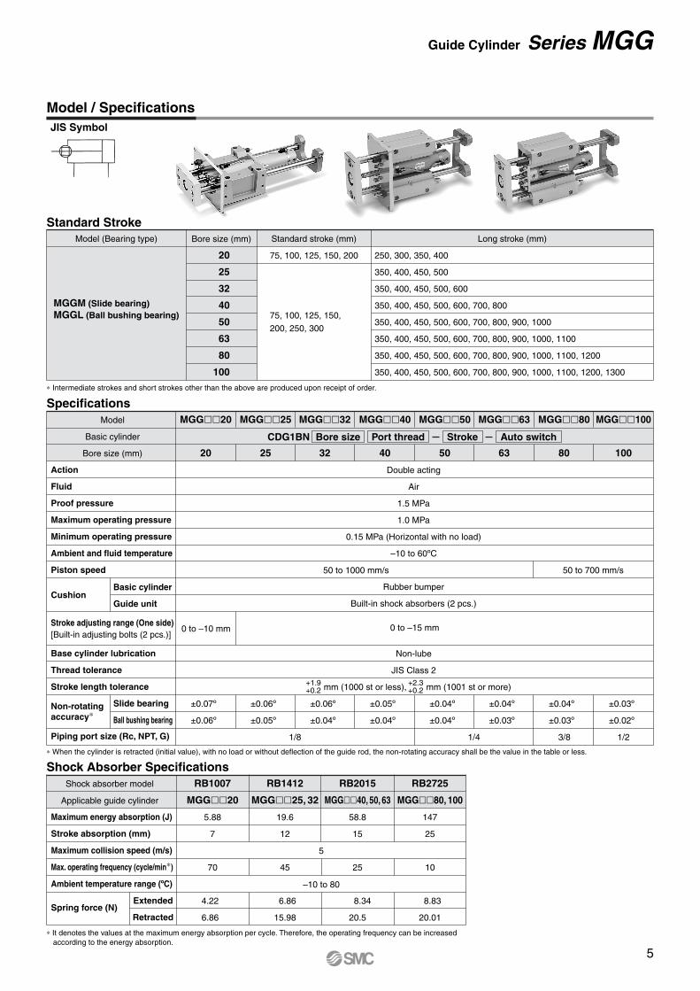
JIS Symbol
Model / Specifications
250, 300, 350, 400
350, 400, 450, 500
350, 400, 450, 500, 600
350, 400, 450, 500, 600, 700, 800
350, 400, 450, 500, 600, 700, 800, 900, 1000
350, 400, 450, 500, 600, 700, 800, 900, 1000, 1100
350, 400, 450, 500, 600, 700, 800, 900, 1000, 1100, 1200
350, 400, 450, 500, 600, 700, 800, 900, 1000, 1100, 1200, 1300
Standard StrokeModel (Bearing type)
MGGM (Slide bearing)MGGL (Ball bushing bearing)
Bore size (mm)
20
25
32
40
50
63
80
100
Standard stroke (mm)
75, 100, 125, 150, 200
75, 100, 125, 150,
200, 250, 300
Long stroke (mm)
∗ Intermediate strokes and short strokes other than the above are produced upon receipt of order.
∗ When the cylinder is retracted (initial value), with no load or without deflection of the guide rod, the non-rotating accuracy shall be the value in the table or less.
Specifications
Action
Fluid
Proof pressure
Maximum operating pressure
Minimum operating pressure
Ambient and fluid temperature
Piston speed
Cushion
Base cylinder lubrication
Thread tolerance
Stroke length tolerance
Non-rotatingaccuracy∗
Piping port size (Rc, NPT, G)
Model
Basic cylinder
Bore size (mm)
MGG��20
20
MGG��25
25
1/8
MGG��32
32
0 to –10 mm
±0.07º
±0.06º
1/4 3/8 1/2
0 to –15 mm
MGG��40
40
MGG��63
63
MGG��50
50
MGG��80
80
MGG��100
100
Double acting
Air
1.5 MPa
1.0 MPa
0.15 MPa (Horizontal with no load)
–10 to 60ºC
Rubber bumper
Built-in shock absorbers (2 pcs.)
Non-lube
JIS Class 2
mm (1000 st or less), mm (1001 st or more)
Basic cylinder
Guide unit
Slide bearing
Ball bushing bearing
50 to 700 mm/s50 to 1000 mm/s
±0.06º
±0.05º
±0.06º
±0.04º
±0.05º
±0.04º
±0.04º
±0.04º
±0.04º
±0.03º
±0.04º
±0.03º
±0.03º
±0.02º
CDG1BN Bore size Port thread Stroke Auto switch
Shock Absorber Specifications
Maximum energy absorption (J)
Stroke absorption (mm)
Maximum collision speed (m/s)
Max. operating frequency (cycle/min∗)
Ambient temperature range (ºC)
Spring force (N)
Shock absorber model
Applicable guide cylinder
RB1007
MGG��20
5.88
7
70
4.22
6.860
RB1412
MGG��25, 32
19.6
12
45
6.86
15.98
RB2015
MGG��40, 50, 63
58.8
15
25
8.34
20.5
RB2725
MGG��80, 100
147
25
10
8.83
20.01
Extended
Retracted
5
–10 to 80
∗ It denotes the values at the maximum energy absorption per cycle. Therefore, the operating frequency can be increased according to the energy absorption.
Stroke adjusting range (One side)[Built-in adjusting bolts (2 pcs.)]
+1.9+0.2
+2.3+0.2
5
Guide Cylinder Series MGG
OUT IN
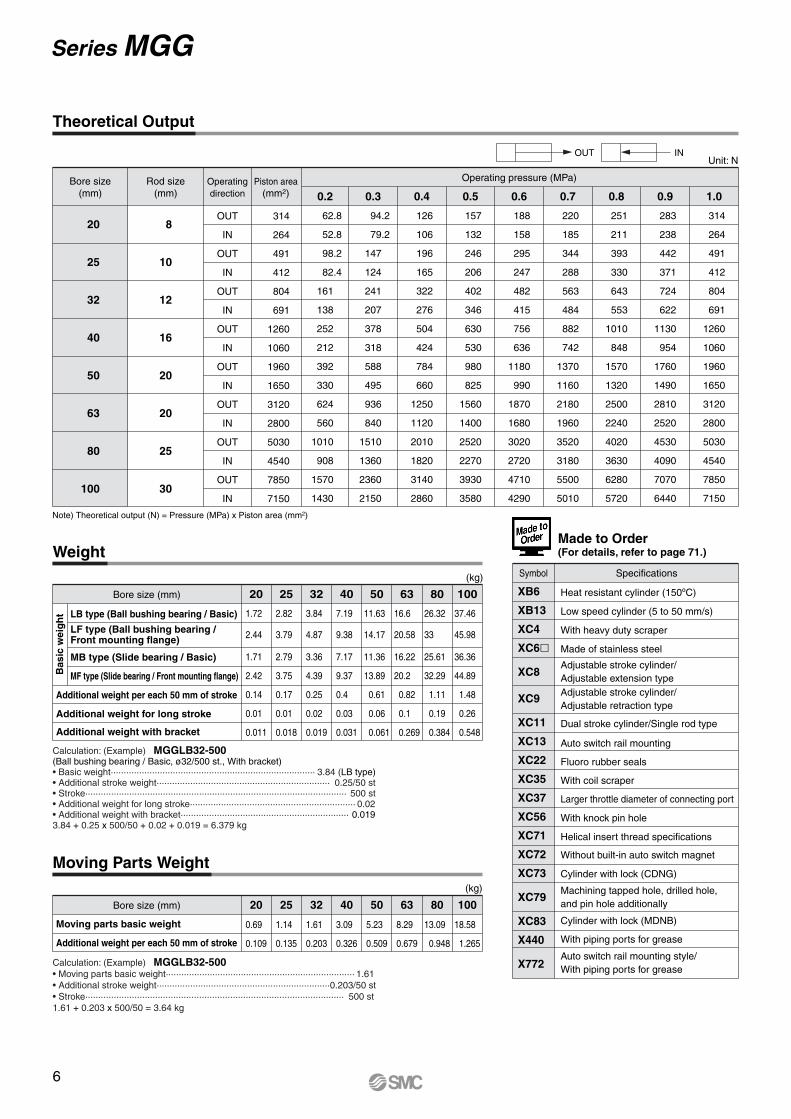
Made to Order (For details, refer to page 71.)
20 25 32 40 50Bore size (mm)
(kg)
1008063
LB type (Ball bushing bearing / Basic)
LF type (Ball bushing bearing / Front mounting flange)
MB type (Slide bearing / Basic)
MF type (Slide bearing / Front mounting flange)
Calculation: (Example) MGGLB32-500(Ball bushing bearing / Basic, ø32/500 st., With bracket)• Basic weight··············································································· 3.84 (LB type)• Additional stroke weight··································································· 0.25/50 st• Stroke····································································································· 500 st• Additional weight for long stroke································································ 0.02• Additional weight with bracket································································· 0.0193.84 + 0.25 x 500/50 + 0.02 + 0.019 = 6.379 kg
Calculation: (Example) MGGLB32-500• Moving parts basic weight········································································· 1.61• Additional stroke weight··································································· 0.203/50 st• Stroke···································································································· 500 st1.61 + 0.203 x 500/50 = 3.64 kg
(kg)
Bore size (mm)
Moving parts basic weight
Additional weight per each 50 mm of stroke
20 25 32 40
0.69
0.109
1.14
0.135
1.61
0.203
3.09
0.326
5.23
0.509
8.29
0.679
13.09
0.948
18.58
1.265
50 63 80 100
Weight
Moving Parts Weight
1.72
2.44
2.82
3.79
3.84
4.87
7.19
9.38
11.63
14.17
37.46
45.98
26.32
33
16.6
20.58
1.71
2.42
0.14
0.01
0.011
2.79
3.75
0.17
0.01
0.018
3.36
4.39
0.25
0.02
0.019
7.17
9.37
0.4
0.03
0.031
11.36
13.89
0.61
0.06
0.061
36.36
44.89
1.48
0.26
0.548
25.61
32.29
1.11
0.19
0.384
16.22
20.2
0.82
0.1
0.269
20
25
32
40
50
63
80
100
Operatingdirection
8
10
12
16
20
20
25
30
OUT
IN
OUT
IN
OUT
IN
OUT
IN
OUT
IN
OUT
IN
OUT
IN
OUT
IN
314
264
491
412
804
691
1260
1060
1960
1650
3120
2800
5030
4540
7850
7150
0.2
62.8
52.8
98.2
82.4
161
138
252
212
392
330
624
560
1010
908
1570
1430
0.3
94.2
79.2
147
124
241
207
378
318
588
495
936
840
1510
1360
2360
2150
0.4
126
106
196
165
322
276
504
424
784
660
1250
1120
2010
1820
3140
2860
0.5
157
132
246
206
402
346
630
530
980
825
1560
1400
2520
2270
3930
3580
0.6
188
158
295
247
482
415
756
636
1180
990
1870
1680
3020
2720
4710
4290
0.7
220
185
344
288
563
484
882
742
1370
1160
2180
1960
3520
3180
5500
5010
0.8
251
211
393
330
643
553
1010
848
1570
1320
2500
2240
4020
3630
6280
5720
0.9
283
238
442
371
724
622
1130
954
1760
1490
2810
2520
4530
4090
7070
6440
1.0
314
264
491
412
804
691
1260
1060
1960
1650
3120
2800
5030
4540
7850
7150
Operating pressure (MPa)
Unit: N
Bore size(mm)
Rod size(mm)
Piston area(mm2)
Note) Theoretical output (N) = Pressure (MPa) x Piston area (mm2)
Heat resistant cylinder (150ºC)
Low speed cylinder (5 to 50 mm/s)
With heavy duty scraper
Made of stainless steel
Adjustable stroke cylinder/Adjustable extension typeAdjustable stroke cylinder/Adjustable retraction type
Dual stroke cylinder/Single rod type
Auto switch rail mounting
Fluoro rubber seals
With coil scraper
Larger throttle diameter of connecting port
With knock pin hole
Helical insert thread specifications
Without built-in auto switch magnet
Cylinder with lock (CDNG)
Machining tapped hole, drilled hole, and pin hole additionally
Cylinder with lock (MDNB)
With piping ports for grease
Symbol Specifications
Auto switch rail mounting style/With piping ports for grease
XB6
XB13
XC4
XC6�
XC8
XC9
XC11
XC13
XC22
XC35
XC37
XC56
XC71
XC72
XC73
XC79
XC83
X440
X772
Additional weight per each 50 mm of stroke
Additional weight for long stroke
Additional weight with bracket
Bas
ic w
eig
ht
6
Theoretical Output
Series MGG
Specifications
Action
Fluid
Proof pressure
Maximum operating pressure
Minimum operating pressure
Piston speed
Cushion
Ambient and fluid temperature
Thread tolerance
Mounting
20, 25, 32, 40, 50, 63Double acting
Turbine oil
1.5 MPa
1.0 MPa
0.18 MPa (Horizontal with no load)
15 to 300 mm/s
Without
Built-in shock absorbers (2 pcs.)
+5 to 60ºC
JIS Class 2
Basic, Front mounting flange
Basic cylinder
Guide unit
MGGHAir-hydro
∗ For specifications other than the above, refer to page 5. ∗ Auto switch can be mounted.
Bearing Mounting Bore size Port thread Stroke
Specifications
Action
Fluid
Maximum operating pressure
Minimum operating pressure
Bearing
Cushion
Mounting
32, 40, 50, 63, 80, 100Double acting
Air
1.0 MPa
0.15 MPa (Horizontal with no load)
Slide bearing
Rubber bumper
Built-in shock absorbers (2 pcs.)
Basic, Front mounting flange
Basic cylinder
Guide unit
∗ For specifications other than the above, refer to page 5. ∗ Auto switch capable (water resistant type)Note) The RBL (coolant resistant type) shock absorbers are used.
MGGM Mounting Bore size Port thread
Q16
17
19
34
46
47
X48
58
69
56
68
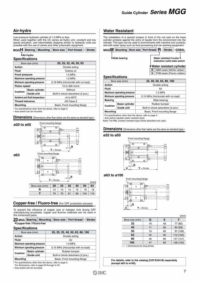
68∗ ( ): Dimensions for long stroke.
For details, refer to the catalog (CAT.E244-B) separately(except ø63 to ø100).
Water resistant cylinderRV
NBR seals (Nitrile rubber)FKM seals (Fluoro rubber)
StrokeR G5BAL
Water resistant 2-colorindication solid state switch
Slide bearing
Low pressure hydraulic cylinder of 1.0 MPa or lessWhen used together with the CC series air-hydro unit, constant and low speed actuation, and intermediate stopping similar to hydraulic units are possible with the use of valves and other pneumatic equipment.
The installation of a special scraper in front of the rod seal on the base cylinder protects against the entry of liquids from the environment into the cylinder. This type can be used in environments with machine tool coolants, and with water spray such as food processing and car washing equipment.
ø32 to ø50
ø63 to ø100
Y + Stroke
QX
Front mounting flange
Bore size (mm)
3240506380
100
Y77 (85)
84 (93)
97 (109)
112 (124)
137 (151)
138 (152)
(mm)
Y + Stroke
QX
Front mounting flange
Bore size (mm)
RY
2014
79
2514
79
3214
81
4015
89
50 16
104
63 16
119
(mm)
ø20 to ø50
ø63
Y + StrokeR
Front mounting flange
Y + StrokeR
Front mounting flange
Dimensions (Dimensions other than below are the same as standard type.)
Dimensions (Dimensions other than below are the same as standard type.)
Basic cylinder
Guide unit
Specifications
Action
Fluid
Maximum operating pressure
Minimum operating pressure
Cushion
Mounting
20, 25, 32, 40, 50, 63, 80, 100Double acting
Air
1.0 MPa
0.15 MPa (Horizontal with no load)
Rubber bumper
Built-in shock absorbers (2 pcs.)
Basic, Front mounting flange∗ For specifications other than the above, refer to page 5. For dimensions, refer to page 20 through to 23. ∗ Auto switch can be mounted.
To prevent the influence of copper ions or halogen ions during CRT manufacturing processes, copper and fluorine materials are not used in the component parts.
Bearing Mounting Bore size Stroke20-MGGCopper-free / Fluoro-free
Port thread
Copper-free / Fluoro-free (For CRT production process)
Bore size (mm)
Bore size (mm)
Bore size (mm)
7
Air-hydro Water Resistant
Guide Cylinder Series MGG
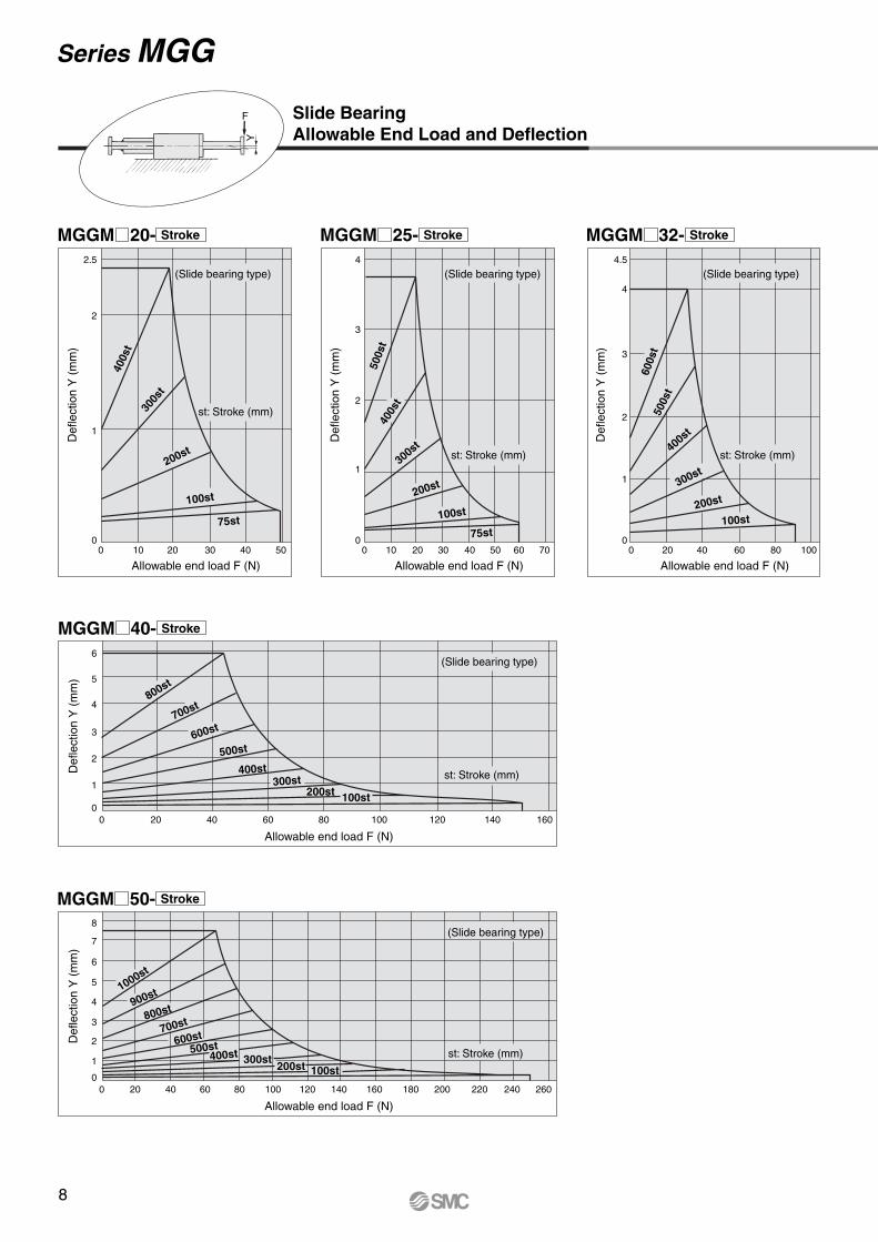
Slide BearingAllowable End Load and Deflection
MGGM 20- Stroke MGGM 25- Stroke MGGM 32- Stroke
MGGM 40- Stroke
MGGM 50- Stroke
00
0
1
2
3
4
5
6
1
2
2.5
(Slide bearing type)
(Slide bearing type)
(Slide bearing type) (Slide bearing type)
400s
t
500s
t
500s
t
600s
t
400s
t
400s
t
300s
t
300st
300st200st
200st
200st100st
100st100st75st
75st
st: Stroke (mm)
st: Stroke (mm)
(Slide bearing type)
st: Stroke (mm)
st: Stroke (mm) st: Stroke (mm)
10
0 20 40 60 80 100 120 140 160
20 30 40 50 00
1
2
3
4
10 20 30 40 50 60 70 00
1
2
3
4
4.5
20 40 60 80 100
Allowable end load F (N)
Allowable end load F (N)
Def
lect
ion
Y (
mm
)D
efle
ctio
n Y
(m
m)
0
1
2
3
4
5
7
6
8
0 20 40 60 80 100 120 140 160 180 200 220 240 260
Allowable end load F (N)
Def
lect
ion
Y (
mm
)
Def
lect
ion
Y (
mm
)
Def
lect
ion
Y (
mm
)
Allowable end load F (N) Allowable end load F (N)
100st
100st200st300st400st500st600st
800st
700st
900st1000st
200st300st
400st500st
600st700st
800st
8
Series MGG
F
Y
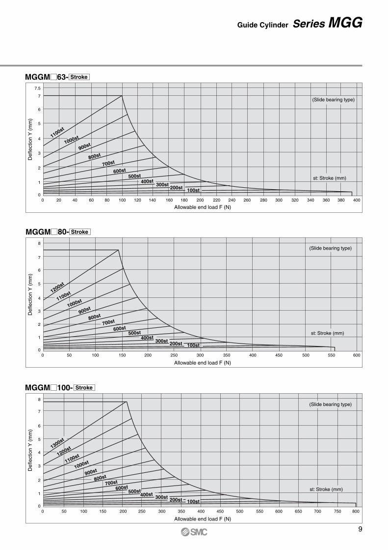
MGGM 63- Stroke
80-MGGM Stroke
MGGM 100- Stroke
0
1
2
3
4
5
6
7
7.5
(Slide bearing type)
st: Stroke (mm)
0 20 40 60 80 100 120 140 160 180 200 220 240 260 280 300 320 340 360 380 400
Allowable end load F (N)
Def
lect
ion
Y (
mm
)
100st200st300st400st
500st600st
700st800st
900st1000st1100st
0
1
2
3
4
5
6
7
8(Slide bearing type)
st: Stroke (mm)
0 50 100 150 200 250 300 350 400 450 500 550 600
Allowable end load F (N)
Def
lect
ion
Y (
mm
)
100st200st300st400st500st
600st700st800st
900st1000st1100st1200st
0
1
2
3
4
5
6
7
8(Slide bearing type)
st: Stroke (mm)
0 50 100 150 200 250 300 350 400 450 500 550 600 650 700 750 800
Allowable end load F (N)
Def
lect
ion
Y (
mm
)
100st200st300st400st500st600st700st800st900st
1000st1100st1200st1300st
9
Guide Cylinder Series MGG
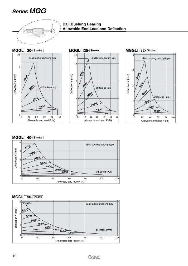
MGGL 20- Stroke MGGL 25- Stroke MGGL 32- Stroke
MGGL 40- Stroke
MGGL 50- Stroke
00
1
2
2.5
(Ball bushing bearing type)
400s
t30
0st
200st
100st
75st
st: Stroke (mm)
10 20 30 40 50
Allowable end load F (N)
Def
lect
ion
Y (
mm
)
(Ball bushing bearing type)
500s
t40
0st
300st
200st
100st
75st
st: Stroke (mm)
00
1
2
3
3.5
10 20 30 40 50 60
Def
lect
ion
Y (
mm
)
Allowable end load F (N)
(Ball bushing bearing type)
500s
t
600s
t
400s
t
300st
200st
100st
st: Stroke (mm)
00
1
2
3
4
20 40 60 80 100
Def
lect
ion
Y (
mm
)
Allowable end load F (N)
0
1
2
3
4(Ball bushing bearing type)
st: Stroke (mm)
0 20 40 60 80 100 120
Allowable end load F (N)
Def
lect
ion
Y (
mm
)
100st200st
300st400st
500st600st
700st
800st
(Ball bushing bearing type)
st: Stroke (mm)
0
1
2
3
0 20 40 60 80 100 120
Allowable end load F (N)
Def
lect
ion
Y (
mm
)
100st
900st
200st300st
400st500st
600st
800st
700st
Ball Bushing BearingAllowable End Load and Deflection
10
Series MGG
F
Y

MGGL 63- Stroke
MGGL 80- Stroke
MGGL 100- Stroke
0
1
2
2.5
(Ball bushing bearing type)
(Ball bushing bearing type)
(Ball bushing bearing type)
st: Stroke (mm)
0 20 40 60 80 100 120 140 160 180
Allowable end load F (N)
Def
lect
ion
Y (
mm
)
100st
900st
200st300st
400st
500st
600st
700st
800st
0
1
2
st: Stroke (mm)
0 20 40 60 80 100 120 140 160 180 200 220
Allowable end load F (N)
Def
lect
ion
Y (
mm
)
100st
900st
200st300st
400st
500st
600st
700st
800st
0
1
2
st: Stroke (mm)
0 20 40 60 80 100 120 140 160 180 200 220 240 260 280 300
Allowable end load F (N)
Def
lect
ion
Y (
mm
)
100st
1000st
200st300st
400st500st
600st
700st
800st
900st
11
Guide Cylinder Series MGG

MGGM 20- Stroke MGGM 25- Stroke MGGM 32- Stroke
MGGM 40- Stroke
MGGM 50- Stroke
00
0.5
1
1.2
400s
t30
0st
200st
100st
75st
st: Stroke (mm)
10 20 30 40 50
Allowable end load F (N)
Def
lect
ion
Y (
mm
)
(Slide bearing type) (Slide bearing type)
(Slide bearing type)
(Slide bearing type)
(Slide bearing type)
500s
t40
0st
300st
200st
100st
75st
st: Stroke (mm)
00
0.5
1
1.5
2
10 20 30 40 50 60 70
Def
lect
ion
Y (
mm
)
Allowable end load F (N)
500s
t
600s
t
400s
t
300st
200st
100st
st: Stroke (mm)
00
0.5
1
1.5
2.2
2
20 40 60 80 100
Def
lect
ion
Y (
mm
)
Allowable end load F (N)
0
0.5
1
1.5
2.5
2
3
st: Stroke (mm)
0 20 40 60 80 100 120 140 160
Allowable end load F (N)
Def
lect
ion
Y (
mm
)
100st200st300st
400st500st
600st700st
800st
st: Stroke (mm)
0
1.5
1
0.5
2.5
2
4
3.5
3
0 20 40 60 80 100 120 140 160 180 200 220 240 260
Allowable end load F (N)
Def
lect
ion
Y (
mm
)
100st200st300st400st500st600st
800st900st1000st
700st
Slide BearingAllowable End Load and Deflection
12
Series MGG
F
Y
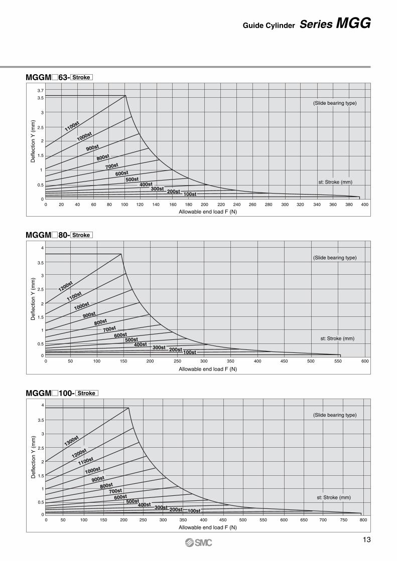
MGGM 63- Stroke
MGGM 80- Stroke
MGGM 100- Stroke
0
1
1.5
0.5
2
2.5
3
3.5
3.7
(Slide bearing type)
(Slide bearing type)
(Slide bearing type)
st: Stroke (mm)
0 20 40 60 80 100 120 140 160 180 200 220 240 260 280 300 320 340 360 380 400
Allowable end load F (N)
Def
lect
ion
Y (
mm
)
100st200st300st400st
500st600st
700st800st
900st1000st
1100st
0
1
0.5
1.5
2
2.5
3
3.5
4
st: Stroke (mm)
0 50 100 150 200 250 300 350 400 450 500 550 600
Allowable end load F (N)
Def
lect
ion
Y (
mm
)
100st200st300st400st500st
600st700st
800st900st
1000st1100st
1200st
0
1.5
2
2.5
0.5
1
3
3.5
4
st: Stroke (mm)
0 10050 150 200 250 300 350 400 450 500 550 600 650 700 750 800
Allowable end load F (N)
Def
lect
ion
Y (
mm
)
100st200st300st400st500st600st
700st800st
900st1000st
1100st1200st1300st
13
Guide Cylinder Series MGG
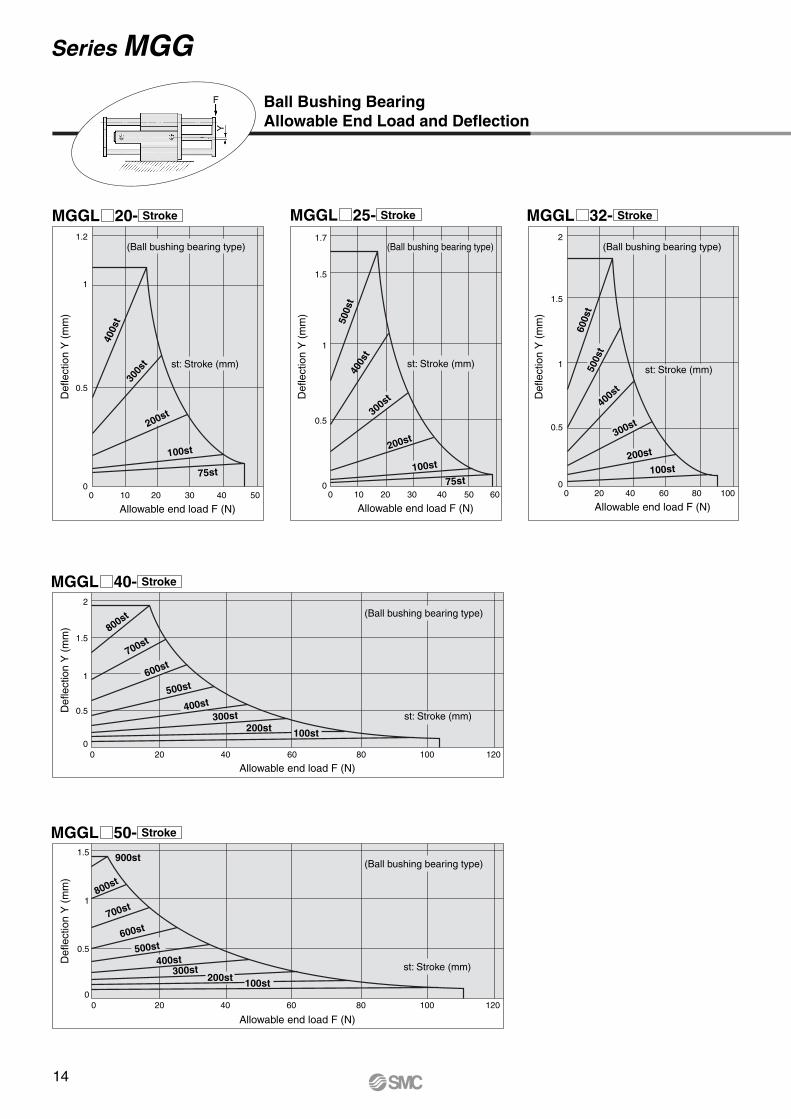
MGGL 20- Stroke MGGL 25- Stroke MGGL 32- Stroke
MGGL 40- Stroke
MGGL 50- Stroke
00
0.5
1
1.2
400s
t30
0st
200st
100st
75st
st: Stroke (mm)
10 20 30 40 50
Allowable end load F (N)
Def
lect
ion
Y (
mm
)
(Ball bushing bearing type) (Ball bushing bearing type)
(Ball bushing bearing type)
(Ball bushing bearing type)
(Ball bushing bearing type)
500s
t40
0st
300st
200st
100st
75st
st: Stroke (mm)
00
0.5
1
1.5
1.7
10 20 30 40 50 60
Def
lect
ion
Y (
mm
)
Allowable end load F (N)
500s
t
600s
t
400s
t
300st
200st
100st
st: Stroke (mm)
00
0.5
1
1.5
2
20 40 60 80 100
Def
lect
ion
Y (
mm
)
Allowable end load F (N)
0
0.5
1
1.5
2
st: Stroke (mm)
0 20 40 60 80 100 120
Allowable end load F (N)
Def
lect
ion
Y (
mm
)
100st200st300st
400st500st
600st700st
800st
0
0.5
1
1.5
st: Stroke (mm)
0 20 40 60 80 100 120
Allowable end load F (N)
Def
lect
ion
Y (
mm
)
100st
900st
200st300st
400st500st
600st700st
800st
Ball Bushing BearingAllowable End Load and Deflection
14
Series MGG
F
Y

MGGL 63- Stroke
MGGL 80- Stroke
MGGL 100- Stroke
0
1
1.2
0.5
(Ball bushing bearing type)
st: Stroke (mm)
0 20 40 60 80 100 120 140 160 180
Allowable end load F (N)
Def
lect
ion
Y (
mm
)
100st
900st
200st300st
400st
500st
600st
700st
800st
0
1
0.5
(Ball bushing bearing type)
st: Stroke (mm)
0 20 40 60 80 100 120 140 160 180 200 220
Allowable end load F (N)
Def
lect
ion
Y (
mm
)
100st
900st
200st300st
400st
500st
600st
700st
800st
0
1
0.5
(Ball bushing bearing type)
st: Stroke (mm)
0 20 40 60 80 100 120 140 160 180 200 220 240 260 280 300
Allowable end load F (N)
Def
lect
ion
Y (
mm
)
100st
1000st
200st300st
400st500st
600st
700st
800st
900st
15
Guide Cylinder Series MGG
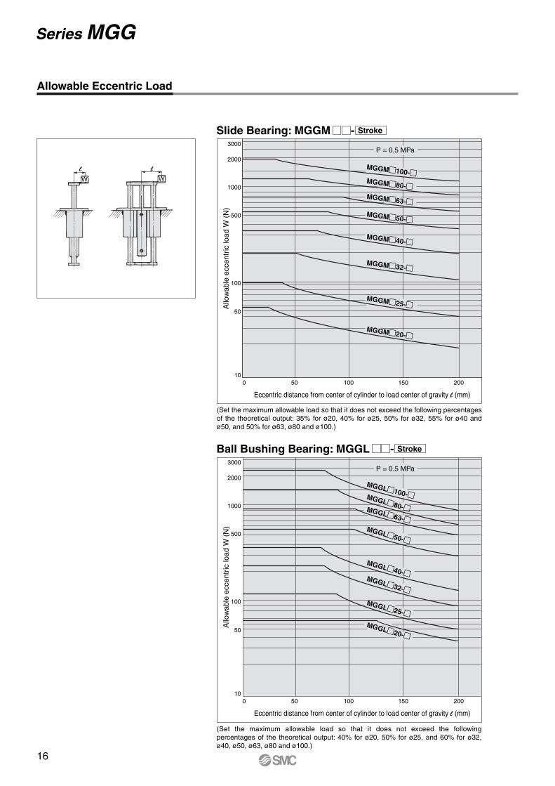
Allowable Eccentric Load
(Set the maximum allowable load so that it does not exceed the following percentages of the theoretical output: 35% for ø20, 40% for ø25, 50% for ø32, 55% for ø40 and ø50, and 50% for ø63, ø80 and ø100.)
(Set the maximum allowable load so that it does not exceed the following percentages of the theoretical output: 40% for ø20, 50% for ø25, and 60% for ø32, ø40, ø50, ø63, ø80 and ø100.)
10
50
100
500
1000
2000
3000P = 0.5 MPa
0 50 100 150 200
Allo
wab
le e
ccen
tric
load
W (
N)
MGGM�100-�MGGM�80-�MGGM�63-�
MGGM�50-�
MGGM�40-�
MGGM�32-�
MGGM�25-�
MGGM�20-�
Eccentric distance from center of cylinder to load center of gravity l (mm)
10
50
100
500
1000
2000
3000P = 0.5 MPa
0 50 100 150 200
Allo
wab
le e
ccen
tric
load
W (
N)
MGGL�100-�MGGL�80-�MGGL�63-�MGGL�50-�
MGGL�40-�MGGL�32-�
MGGL�25-�
MGGL�20-�
Eccentric distance from center of cylinder to load center of gravity l (mm)
l l
Slide Bearing: MGGM - Stroke
Ball Bushing Bearing: MGGL - Stroke
16
Series MGG

Construction
MGG��ø20 to ø50
Component Parts
293031323334353637383940
Adjusting boltNutParallel pinGrease nippleHexagon socket head cap screw
Hexagon socket head cap screw
Guide boltHexagon socket head cap screw
Hexagon socket head cap screw
Rod sealPiston sealTube gasket
Rolled steelRolled steel
High carbon chrome bearing steel
—Chromium molybdenum steel
Chromium molybdenum steel
Chromium molybdenum steel
Chromium molybdenum steel
Chromium molybdenum steel
NBRNBRNBR
Nickel platedNickel platedNickel platedNickel plated
For cylinder mountingFor large/small flange mounting
For front plate mountingFor rear plate mountingFor bracket mounting
Nickel platedNickel platedNickel platedNickel platedNickel plated
DescriptionNo. Material Note
Component Parts
123456789101112131415
16
1718
19
20
2122232425262728
DescriptionRod coverTube coverPiston Piston rodBushingBumper ABumper BMagnetSnap ringWear ringRod end nutPiston gasketHead coverCylinder tubeGuide bodySmall flangeLarge flangeFront plateRear plateSlide bearingBall bushing bearing
Guide rod
End bracketPlain washerSpring washerFeltHolderC-type snap ring for holeBracketShock absorber
Aluminum alloyAluminum alloyAluminum alloyCarbon steelBearing alloy
UrethaneUrethane
—Stainless steal
ResinRolled steel
NBRAluminum alloyAluminum alloyAluminum alloy
Rolled steel
Rolled steelCast iron
Bearing alloy—
Carbon steelHigh carbon chrome bearing steel
Carbon steelRolled steelSteel wire
FeltStainless steel
Carbon tool steelStainless steel
—
Material
White hard anodizedHard anodized
Nickel plated
For long stroke
Hard chrome plated ø20, ø25 are stainless steel
No.
Hard chrome platedQuenched, hard chrome plated
For slide bearingFor ball bushing bearing
White hard anodizedWhite hard anodized
Chromated
ø40 and larger are the same as bumper A
Nickel plated
White anodized
Flat nickel platedMetallic gold
For slide bearingFor ball bushing bearing
Nickel platedNickel platedNickel plated
Nickel plated
Note
∗ Seal kit includes #8 to $0. Order the seal kit, based on each bore size.
Bore size (mm) Kit no.CG1N20-PSCG1N25-PSCG1N32-PSCG1N40-PS
Contents20253240
Replacement Parts: Seal Kit
Set of nos. above#8, #9, $0.
When disassembling basic cylinders with bore sizes of ø20 through ø40, grip the double flat part of either the head cover or the rod cover with a vise and loosen the other side with a wrench or a monkey wrench, etc., and then remove the cover. When re-tightening, tighten approximately 2 degrees more than the original position.(Cylinders with ø50 or larger bore sizes are tightened with a large tightening torque and cannot be disassembled. Please contact SMC when disassembly is required.)
Caution
BasicFont mounting flange
Ball bushing bearing
A
A'
View A-A'
Slide bearingLong stroke
Front mounting flange
!6
!7
#5
@3
@2
@1
!1
#3
#4
qt w r y!5 !9 !2 !0 !8i e u o @0$0#8 #9 #6@4 @5 @6
#2 @7 #7
!9!3$0#0
#1
@8 !4
@9
17
Guide Cylinder Series MGG
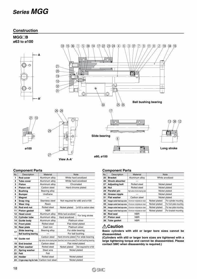
Construction
MGG�Bø63 to ø100
Component Parts
2526272829303132333435363738
BracketShock absorberAdjusting boltNutParallel pinGrease nippleFlat washerHexagon socket head cap screw
Hexagon socket head cap screw
Hexagon socket head cap screw
Hexagon socket head cap screw
Rod sealPiston sealTube gasket
Aluminum alloy—
Rolled steelRolled steel
High carbon chrome bearing steel
—Carbon steel
Chromium molybdenum steel
Chromium molybdenum steel
Chromium molybdenum steel
Chromium molybdenum steel
NBRNBRNBR
White anodized
Nickel platedNickel platedNickel platedNickel platedNickel plated
For cylinder mountingFor front plate mountingFor rear plate mountingFor bracket mounting
Nickel platedNickel platedNickel platedNickel plated
DescriptionNo. Material Note
Component PartsNote
White hard anodizedHard anodized
Hard chrome platedQuenched, hard chrome plated
For slide bearingFor ball bushing bearing
For long stroke
Nickel plated ø100 is carbon steel
Nickel plated Not required for ø100
Flat nickel plated
Nickel plated
Nickel platedNickel plated
Aluminum alloyAluminum alloyAluminum alloyCarbon steelBearing alloy
Urethane—
Stainless steelResin
Rolled steelNBR
Aluminum alloyAluminum alloyAluminum alloy
Rolled steelCast iron
Bearing alloy—
Carbon steelHigh carbon chrome bearing steel
Carbon steelRolled steelSteel wire
FeltRolled steel
Carbon tool steel
Material12345678910111213141516
17
18
192021222324
DescriptionRod coverTube coverPiston Piston rodBushingBumperMagnetSnap ringWear ringRod end nutPiston gasketHead coverCylinder tubeGuide bodyFront plateRear plateSlide bearingBall bushing bearing
Guide rod
End bracketPlain washerSpring washerFeltHolderC-type snap ring for hole
No.White hard anodizedWhite hard anodized
ChromatedHard chrome plated
Not required for ø80 and ø100
Platinum silverFlat nickel platedPlatinum silver
For slide bearingFor ball bushing
Basic cylinders with ø50 or larger bore sizes cannot be disassembled.(Cylinders with ø50 or larger bore sizes are tightened with a large tightening torque and cannot be disassembled. Please contact SMC when disassembly is required.)
Caution
Long stroke
Slide bearing
ø80, ø100
ø100
View A-A'
#3 !5 #6 q t #8 !4 !7 @2 @3 @4 r y e #7 u o !1 i w !8 #4 !6
#5@5#0
#1
@6
@9
@7
@8 !7
y
!3 #8 !2@1 !0
#2
!0
!9
@0
@1
Ball bushing bearing
A
A'
18
Series MGG

MGG�Fø63 to ø100
Component Parts
12345678910111213141516
17
18
19202122232425
DescriptionRod coverTube coverPiston Piston rodBushingBumperMagnetSnap ringWear ringRod end nutPiston gasketHead coverCylinder tubeGuide bodyFront plateRear plateSlide bearingBall bushing bearing
Guide rod
End bracketPlain washerSpring washerFeltHolderC-type snap ring for holeBracket
MaterialAluminum alloyAluminum alloyAluminum alloyCarbon steelBearing alloy
Urethane—
Stainless steelResin
Rolled steelNBR
Aluminum alloyAluminum alloyAluminum alloy
Rolled steelCast iron
Bearing alloy—
Carbon steelHigh carbon chrome bearing steel
Carbon steelRolled steelSteel wire
FeltRolled steel
Carbon tool steelAluminum alloy
NoteWhite hard anodizedWhite hard anodized
ChromatedHard chrome plated
Not required for ø80 and ø100
Platinum silverFlat nickel platedPlatinum silver
For slide bearingFor ball bushing
Flat nickel plated
Nickel plated
Nickel platedNickel plated
White anodized
White hard anodizedHard anodized
Hard chrome platedQuenched, hard chrome plated
For slide bearingFor ball bushing bearing
For long stroke
No.
Nickel plated ø100 is carbon steel
Nickel plated Not required for ø100
Component Parts
262728293031323334353637383940
Shock absorberAdjusting boltNutParallel pinGrease nipple —Hexagon socket head cap screw
Hexagon socket head cap screw
Hexagon socket head cap screw
Hexagon socket head cap screw
Rod sealPiston sealTube gasketLarge flangeHexagon socket head cap screw
—Rolled steelRolled steel
High carbon chrome bearing steel
——
Chromium molybdenum steel
Chromium molybdenum steel
Chromium molybdenum steel
Chromium molybdenum steel
NBRNBRNBR
Rolled steelChromium molybdenum steel
Nickel platedNickel platedNickel platedNickel plated
For cylinder mountingFor front plate mountingFor rear plate mountingFor bracket mounting
Nickel platedNickel platedNickel platedNickel plated
DescriptionNo.
Flat nickel platedNickel plated For large flange mounting
Material Note
Basic cylinders with ø50 or larger bore sizes cannot be disassembled.(Cylinders with ø50 or larger bore sizes are tightened with a large tightening torque and cannot be disassembled. Please contact SMC when disassembly is required.)
Caution
Construction
Ball bushing bearing
#3 !5 #9 #6 q t #8 !4 !7 @2 @3 @4 r y e #7 u o !1 i w !8 #4 !6
#5@5#0
@1
@0
!9
!0
#2
$0
@8@6
@9
!0@1
@7
!7
!3 #8 !2
y
Long strokeø100
ø80, ø100
Slide bearing
View A-A'
A
A'
19
Guide Cylinder Series MGG
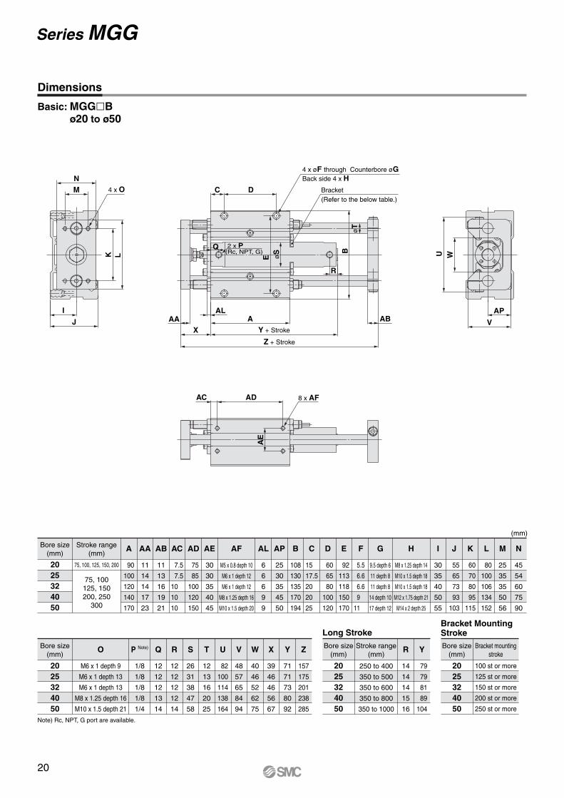
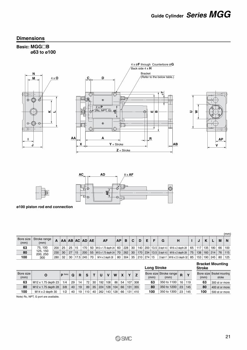
Dimensions
Basic: MGG�Bø20 to ø50
Bore size(mm)
2025324050
Stroke range(mm)
75, 100, 125, 150, 200
75, 100125, 150200, 250
300
A
90
100
120
140
170
AA
11
14
14
17
23
AB
11
13
16
19
21
AC
7.5
7.5
10
10
10
AD
75
85
100
120
150
AE
30
30
35
40
45
AF
M5 x 0.8 depth 10
M6 x 1 depth 12
M6 x 1 depth 12
M8 x 1.25 depth 16
M10 x 1.5 depth 20
AP
25
30
35
45
50
AL
6
6
6
9
9
B
108
130
135
170
194
C
15
17.5
20
20
25
D
60
65
80
100
120
E
92
113
118
150
170
F
5.5
6.6
6.6
9
11
G
9.5 depth 6
11 depth 8
11 depth 8
14 depth 10
17 depth 12
H
M8 x 1.25 depth 14
M10 x 1.5 depth 18
M10 x 1.5 depth 18
M12 x 1.75 depth 21
M14 x 2 depth 25
I
30
35
40
50
55
J
55
65
73
93
103
K
60
70
80
95
115
L
80
100
106
134
152
M
25
35
35
50
56
N
45
54
60
75
90
(mm)
Bore size(mm)
2025324050
250 to 400
350 to 500
350 to 600
350 to 800
350 to 1000
R
14
14
14
15
16
Y
79
79
81
89
104
Stroke range(mm)
Long StrokeBore size
(mm)
2025324050
100 st or more
125 st or more
150 st or more
200 st or more
250 st or more
Bracket mountingstroke
Bracket MountingStroke
Bore size(mm)
2025324050
O
M6 x 1 depth 9
M6 x 1 depth 13
M6 x 1 depth 13
M8 x 1.25 depth 16
M10 x 1.5 depth 21
P Note)
1/8
1/8
1/8
1/8
1/4
Q
12
12
12
13
14
R
12
12
12
12
14
S
26
31
38
47
58
T
12
13
16
20
25
U
82
100
114
138
164
V
48
57
65
84
94
W
40
46
52
62
75
X
39
46
46
56
67
Y
71
71
73
80
92
Z
157
175
201
238
285
Note) Rc, NPT, G port are available.
NM
I
J
K L
4 x O
Z + Stroke
Y + Stroke
Bracket(Refer to the below table.)
AAAL
XA AB
R
AP
V
C
Q
D
B
WUE
øT
2 x P(Rc, NPT, G)
øS
4 x øF through Counterbore øGBack side 4 x H
8 x AFAC AD
AE
20
Series MGG
Bore size(mm)
6380
100
Bore size(mm)
6380
100
Bracket mountingstroke
Bore size(mm)
6380
100
Stroke range(mm)
Long StrokeBracket MountingStroke
Bore size(mm)
6380
100
Stroke range(mm)
75, 100125, 150200, 250
300
300 st or more
400 st or more
500 st or more
O P Note) Q R S T U V W X Y Z R Y
A AA AB AC AD AE AF AP B C D E F G H I J K L M N
M12 x 1.75 depth 23
M12 x 1.75 depth 28
M14 x 2 depth 30
1/4
3/8
1/2
29
40
40
14
19
19
72
89
110
30
35
40
192
224
262
108
128
143
86
104
128
54
66
66
107
131
131
308
355
410
350 to 1100
350 to 1200
350 to 1300
16
23
23
119
145
145
200
230
280
25
30
32
25
27
30
15
15
17.5
170
200
245
50
55
70
M12 x 1.75 depth 24
M12 x 1.75 depth 24
M14 x 2 depth 28
60
70
80
228
262
304
30
30
35
140
170
210
200
234
274
13.5
13.5
15
20 depth 14.5
20 depth 14.5
23 depth 17
M16 x 2 depth 28
M16 x 2 depth 28
M18 x 2.5 depth 32
65
75
85
117
138
153
135
160
190
180
214
245
66
76
80
100
115
125
(mm)
Basic: MGG�Bø63 to ø100
Dimensions
Note) Rc, NPT, G port are available.
ø100 piston rod end connection
Y + Stroke
Z + Stroke
Bracket(Refer to the below table.)
AA A R
X AB
4 x øF through Counterbore øGBack side 4 x H
C D
E B
øT
2 x P(Rc, NPT, G)
8 x AF
MN
K L
I
J
4 x O
U W
AP
V
AC AD
øS
Q
AE
21
Guide Cylinder Series MGG
Bore size(mm)
2025324050
Stroke range(mm)
75, 100, 125, 150, 200
75, 100125, 150200, 250
300
A AA AB AG AH AI AJ AK AL AM AN AO AP B I J K L M N O
(mm)
Bore size(mm)
2025324050
P Note) Q R S T U V W X Y Z Bore size(mm)
2025324050
250 to 400
350 to 500
350 to 600
350 to 800
350 to 1000
R Y
90
100
120
140
170
11
14
14
17
23
11
13
16
19
21
112
134
134
170
190
125
150
150
186
210
82
92
102
134
140
95
108
118
150
160
6.6
9
9
9
11
9
9
9
12
12
65
75
85
105
115
115
135
140
175
200
M6
M8
M8
M8
M10
25
30
35
45
50
108
130
135
170
194
30
35
40
50
55
55
65
73
93
103
60
70
80
95
115
80
100
106
134
152
25
35
35
50
56
45
54
60
75
90
M6 x 1 depth 9
M6 x 1 depth 13
M6 x 1 depth 13
M8 x 1.25 depth 16
M10 x 1.5 depth 21
1/8
1/8
1/8
1/8
1/4
12
12
12
13
14
12
12
12
12
14
26
31
38
47
58
12
13
16
20
25
82
100
114
138
164
48
57
65
84
94
40
46
52
62
75
39
46
46
56
67
71
71
73
80
92
157
175
201
238
285
14
14
14
15
16
79
79
81
89
104
Stroke range(mm)
Long StrokeBore size
(mm)
2025324050
100 st or more
125 st or more
150 st or more
200 st or more
250 st or more
Bracket mountingstroke
Bracket Mounting Stroke
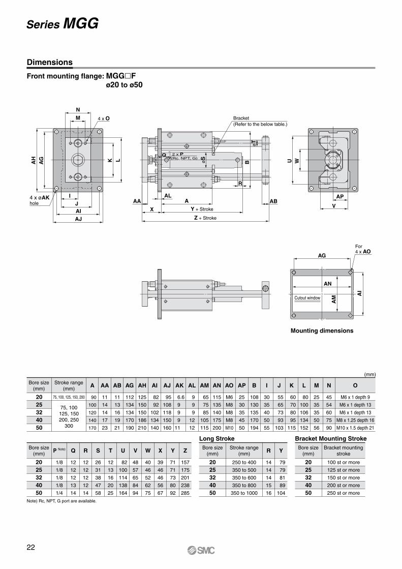
Dimensions
Front mounting flange: MGG�Fø20 to ø50
Note) Rc, NPT, G port are available.
Y + Stroke
Z + Stroke
AAL
M
NKAH
AG L
IJAIAJ
4 x O
For 4 x AO
Bracket(Refer to the below table.)
AA
X
øT
2 x P(Rc, NPT, G)
Q
AB
AG
AN
V
APøS
B U W
AI
AM
R
Cutout window
Mounting dimensions
4 x øAK hole
22
Series MGG
Bore size(mm)
6380
100
Q R S T U V W X Y Z Bore size(mm)
6380
100
350 to 1100
350 to 1200
350 to 1300
R YStroke range(mm)
Long StrokeBore size
(mm)
6380
100
300 st or more
400 st or more
500 st or more
Bracket mountingstroke
Bracket Mounting Stroke
Bore size(mm)
6380
100
Stroke range(mm)
75, 100125, 150200, 250
300
A AA AB AG AH AI AJ AK AL AM AN AO AP B I J K L M N
(mm)
O P Note)
29
40
40
14
19
19
72
89
110
30
35
40
192
224
262
108
128
143
86
104
128
54
66
66
107
131
131
308
355
410
16
23
23
119
145
145
200
230
280
25
30
32
25
27
30
228
262
300
250
284
326
158
178
200
180
200
226
14
14
16
12
16
16
135
155
175
234
268
310
M12
M12
M14
60
70
80
228
262
304
65
75
85
117
138
153
135
160
190
180
214
245
66
76
80
100
115
125
M12 x 1.75 depth 23
M12 x 1.75 depth 28
M14 x 2 depth 30
1/4
3/8
1/2
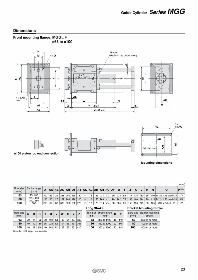
Front mounting flange: MGG�Fø63 to ø100
Dimensions
Note) Rc, NPT, G port are available.
(Rc, NPT, G)
Y + Stroke
Z + Stroke
Bracket(Refer to the below table.)
AA
V
AN
AG
X AB
A
Q
I
J
AI
AJ
R
M
N
AH
AG K øS
øT
L UB
AI
AM
W
4 x O
For 4 x AO
2 x P
4 x øAK hole
Mounting dimensions
ø100 piston rod end connection
ALAP
Cutout window
23
Guide Cylinder Series MGG
32
Series MGG
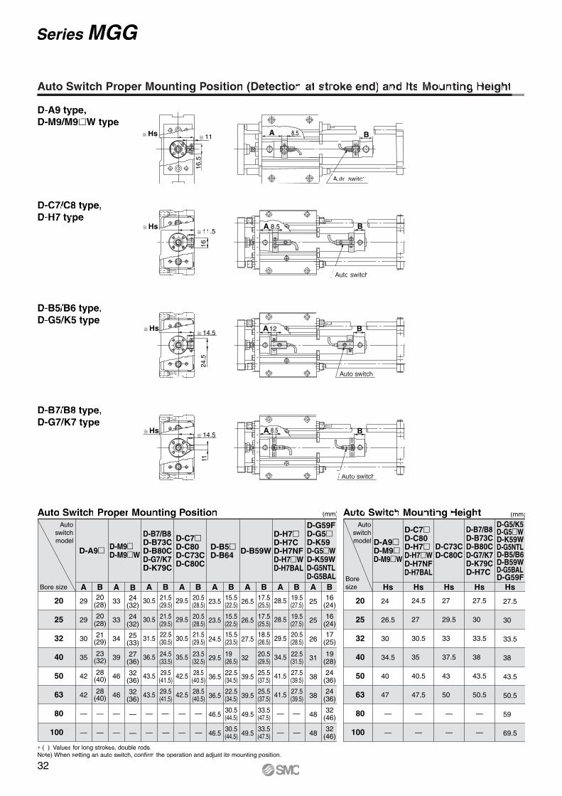
Auto Switch Proper Mounting Position (Detection at stroke end) and Its Mounting Height
Auto switch
A B8.5≅ Hs ≅ 11.5
16
Auto switch
A B12 ≅ Hs ≅ 14.5
24.5
Auto switch
A B8.5 ≅ Hs ≅ 14.5
11
BA ≅ 11 ≅ Hs
16.5
Auto switch
8.5
D-A9 type,D-M9/M9�W type
D-B7/B8 type,D-G7/K7 type
D-B5/B6 type,D-G5/K5 type
D-C7/C8 type,D-H7 type
∗ ( ): Values for long strokes, double rods.Note) When setting an auto switch, confirm the operation and adjust its mounting position.
Auto Switch Proper Mounting Position (mm)
Bore size
Autoswitchmodel
20
25
32
40
50
63
80
100
D-M9�D-M9�W
A
33
33
34
39
46
46
—
—
B24
(32)
24(32)
25(33)
27(36)
32(36)
32(36)
—
—
D-A9�
A
29
29
30
35
42
42
—
—
B20
(28)
20(28)
21(29)
23(32)
28(40)
28(40)
—
—
30.5
30.5
31.5
36.5
43.5
43.5
—
—
A21.5(29.5)
21.5(29.5)
22.5(30.5)
24.5(33.5)
29.5(41.5)
B20.5(28.5)
20.5(28.5)
21.5(29.5)
23.5(32.5)
28.5(40.5)
B15.5(22.5)
15.5(22.5)
15.5(23.5)
19 (26.5)
22.5(34.5)
B17.5(25.5)
17.5(25.5)
18.5(26.5)
20.5(29.5)
25.5(37.5)
B19.5(27.5)
19.5(27.5)
20.5(28.5)
22.5(31.5)
27.5(39.5)
B16
(24)
16(24)
17(25)
19(28)
24(36)
29.5(41.5)
—
—
28.5(40.5)
—
—
22.5(34.5)
30.5(44.5)
30.5(44.5)
25.5(37.5)
33.5(47.5)
33.5(47.5)
27.5(39.5)
—
—
24(36)
32(46)
32(46)
B
29.5
29.5
30.5
35.5
42.5
42.5
—
—
A
23.5
23.5
24.5
29.5
36.5
36.5
46.5
46.5
A
26.5
26.5
27.5
32
39.5
39.5
49.5
49.5
A
28.5
28.5
29.5
34.5
41.5
41.5
—
—
A
25
25
26
31
38
38
48
48
A
D-B7/B8D-B73CD-B80CD-G7/K7D-K79C
D-C7�D-C80D-C73CD-C80C
D-B5�D-B64 D-B59W
D-H7�D-H7CD-H7NFD-H7�WD-H7BAL
D-G59FD-G5�D-K59D-G5�WD-K59WD-G5NTLD-G5BAL
Hs
24
26.5
30
34.5
40
47
—
—
Auto Switch Mounting Height
D-A9�D-M9�D-M9�W
Boresize
Autoswitchmodel
20
25
32
40
50
63
80
100
(mm)
24.5
27
30.5
35
40.5
47.5
—
—
Hs
27
29.5
33
37.5
43
50
—
—
Hs
27.5
30
33.5
38
43.5
50.5
—
—
Hs Hs
27.5
30
33.5
38
43.5
50.5
59
69.5
D-C73CD-C80C
D-B7/B8D-B73CD-B80CD-G7/K7D-K79CD-H7C
D-C7�D-C80D-H7�D-H7�WD-H7NFD-H7BAL
D-G5/K5D-G5�WD-K59WD-G5NTLD-B5/B6D-B59WD-G5BALD-G59F
35
Series MGGGuide CylinderWith End Lock
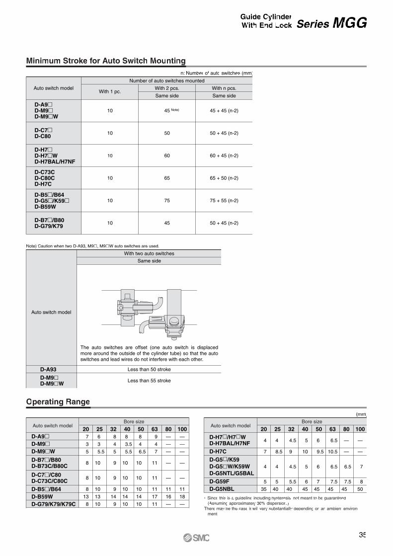
Operating Range
Auto switch modelBore size
20 7
3
5
8
8
8
13
8
256
3
5.5
10
10
10
13
10
32 8
4
5
9
9
9
14
9
408
3.5
5.5
10
10
10
14
10
508
4
6.5
10
10
10
14
10
63 9
4
7
11
11
11
17
11
80—
—
—
—
—
11
16
—
100—
—
—
—
—
11
18
—
D-A9�D-M9�D-M9�W
D-B7�/B80D-B73C/B80C
D-C7�/C80D-C73C/C80CD-B5�/B64D-B59WD-G79/K79/K79C
∗ Since this is a guideline including hysteresis, not meant to be guaranteed. (Assuming approximately 30% dispersion.)
There may be the case it will vary substantially depending on an ambient environ-ment.
Auto switch modelBore size
20
4
7
4
5
35
25
4
8.5
4
5
40
32
4.5
9
4.5
5.5
40
40
5
10
5
6
45
50
6
9.5
6
7
45
63
6.5
10.5
6.5
7.5
45
80
—
—
6.5
7.5
45
100
—
—
7
8
50
(mm)
D-H7�/H7�WD-H7BAL/H7NFD-H7CD-G5�/K59D-G5�W/K59WD-G5NTL/G5BALD-G59FD-G5NBL
Minimum Stroke for Auto Switch Mounting
D-H7�D-H7�WD-H7BAL/H7NF
D-C7�D-C80
D-B5�/B64D-G5�/K59�D-B59W
10 50
10 60
10 65
50 + 45 (n-2)
60 + 45 (n-2)
65 + 50 (n-2)
75 + 55 (n-2)10 75
D-A9�D-M9�D-M9�W
Auto switch modelWith 1 pc.
With 2 pcs. With n pcs.
Number of auto switches mounted
10 Note)
Same side
45
Same side
45 + 45 (n-2)
n: Number of auto switches (mm)
D-B7�/B80D-G79/K79
50 + 45 (n-2)10 45
D-C73CD-C80CD-H7C
D-A93D-M9�D-M9�W
Auto switch model
With two auto switches
Same side
Less than 50 stroke
Less than 55 stroke
The auto switches are offset (one auto switch is displaced more around the outside of the cylinder tube) so that the auto switches and lead wires do not interfere with each other.
Note) Caution when two D-A93, M9�, M9�W auto switches are used.
36
Series MGG
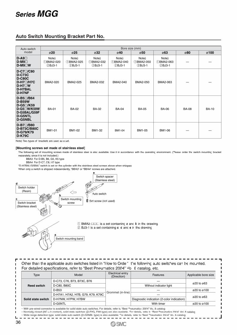
[Mounting screws set made of stainless steel]The following set of mounting screws made of stainless steel is also available. Use it in accordance with the operating environment. (Please order the switch mounting bracket separately, since it is not included.)
BBA3: For D-B5, B6, G5, K5 type BBA4: For D-C7, C8, H7 type
“D-H7BAL/G5BAL” switch is set on the cylinder with the stainless steel screws above when shipped. When only a switch is shipped independently, “BBA3” or “BBA4” screws are attached.
Auto switchmodel
Bore size (mm)
D-C7�/C80D-C73CD-C80CD-H7�/H7CD-H7�WD-H7BALD-H7NF
D-B5�/B64D-B59WD-G5�/K59D-G5�W/K59WD-G5BAL/G59FD-G5NTLD-G5NBL
D-A9�D-M9�D-M9�W
D-B7�/B80D-B73C/B80CD-G79/K79D-K79C
ø20 ø25
BMA2-020 BMA2-025
ø32
BMA2-032
BA-01 BA-02 BA-32
Note)qBMA2-020
wBJ3-1
Note)qBMA2-025
wBJ3-1
Note)qBMA2-032
wBJ3-1
ø40
BMA2-040
BA-04
Note)qBMA2-040
wBJ3-1
ø50
BMA2-050
BA-05
Note)qBMA2-050
wBJ3-1
ø63
BMA2-063
BA-06
Note)qBMA2-063
wBJ3-1
ø80
—
BA-08
— —
ø100
—
BA-10
BM1-01 BM1-02 BM1-32 BM1-04 BM1-05 BM1-06 — —
Note) Two types of brackets are used as a set.
Auto Switch Mounting Bracket Part No.
∗ With pre-wired connector is available for solid state auto switches. For details, refer to “Best Pneumatics 2004” Vol. 8 catalog. ∗ Normally closed (NC = b contact), solid state switches (D-F9G, F9H type) are also available. For details, refer to “Best Pneumatics 2004” Vol. 8 catalog.∗ Wide range detection type, solid state auto switch (D-G5NBL type) is also available. For details, refer to “Best Pneumatics 2004” Vol. 8 catalog.
Type Model FeaturesElectrical entry(Direction)
D-C73, C76, B73, B73C, B76
D-C80, B80C
D-B53
D-H7A1, H7A2, H7B, G79, K79, K79C
D-H7NW, H7PW, H7BW
D-G5NTL
—
Without indicator light
—
—
Diagnostic indication (2-color indication)
With timer
ø20 to ø63
ø20 to ø100
ø20 to ø63
ø20 to ø100
Applicable bore size
Grommet (in-line)
Other than the applicable auto switches listed in “How to Order”, the following auto switches can be mounted.For detailed specifications, refer to “Best Pneumatics 2004” Vol. 8 catalog, etc.
Reed switch
Solid state switch
q BMA2-��� is a set containing a and b in the drawing. w BJ3-1 is a set containing c, d and e in the drawing.
Switch spacer(Stainless steel)
e
Switch mountingscrew
b
Switch mounting banda
Auto switch
Set screw (not used)
Switch holder(Resin)
d
Switch bracket(Stainless steel)
c
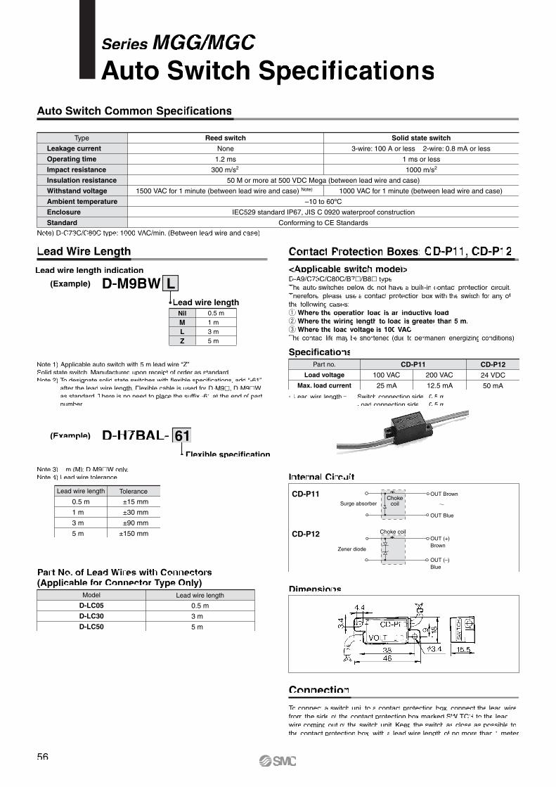
Series MGG/MGCAuto Switch Specifications
Auto Switch Common Specifications
Type
Leakage current
Operating time
Impact resistance
Insulation resistance
Withstand voltage
Ambient temperature
Enclosure
Standard
Reed switch
None
1.2 ms
300 m/s2
50 M or more at 500 VDC Mega (between lead wire and case)
–10 to 60ºC
Conforming to CE Standards
IEC529 standard IP67, JIS C 0920 waterproof construction
Solid state switch
3-wire: 100 A or less 2-wire: 0.8 mA or less
1 ms or less
1000 m/s2
1500 VAC for 1 minute (between lead wire and case) Note) 1000 VAC for 1 minute (between lead wire and case)
Lead Wire Length
Lead wire length indication
(Example)
LM
0.5 m
3 m1 m
5 mZ
Nil
Lead wire length
LD-M9BW
(Example)
Flexible specification
61D-H7BAL-
Contact Protection Boxes: CD-P11, CD-P12<Applicable switch model>
Specifications
Internal Circuit
Dimensions
Connection
∗ Lead wire length Switch connection side 0.5 m Load connection side 0.5 m
D-A9/C73C/C80C/B7�/B8� typeThe auto switches below do not have a built-in contact protection circuit.Therefore, please use a contact protection box with the switch for any of the following cases:q Where the operation load is an inductive load.w Where the wiring length to load is greater than 5 m. e Where the load voltage is 100 VAC.The contact life may be shortened (due to permanent energizing conditions).
Part no.
Load voltage
Max. load current
CD-P11
CD-P11
100 VAC
25 mA
200 VAC
12.5 mA
CD-P12
24 VDC
50 mA
To connect a switch unit to a contact protection box, connect the lead wire from the side of the contact protection box marked SWITCH to the leadwire coming out of the switch unit. Keep the switch as close as possible to the contact protection box, with a lead wire length of no more than 1 meter.
CD-P12
Note 1) Applicable auto switch with 5 m lead wire “Z”Solid state switch: Manufactured upon receipt of order as standard.Note 2) To designate solid state switches with flexible specifications, add “-61”
after the lead wire length. Flexible cable is used for D-M9�, D-M9�W as standard. There is no need to place the suffix -61 at the end of part number.
Note 3) 1 m (M): D-M9�W only.Note 4) Lead wire tolerance
Lead wire length Tolerance
±15 mm
±30 mm
±90 mm
±150 mm
0.5 m
1 m
3 m
5 m
Part No. of Lead Wires with Connectors (Applicable for Connector Type Only)
Model
D-LC05
D-LC30
D-LC50
Lead wire length
0.5 m
3 m
5 m
Note) D-C73C/C80C type: 1000 VAC/min. (Between lead wire and case)
Surge absorberChoke
coil
OUT Brown
OUT Blue
OUT (+)Brown
OUT (–)Blue
Choke coil
Zener diode
56

Auto SwitchConnections and Examples
Basic Wiring
Solid state 3-wire, NPN 2-wireSolid state 3-wire, PNP(Solid state)
2-wire(Reed)
• Sink input specification3-wire, NPN
• 3-wire
• Source input specification3-wire, PNP
OR connection for NPN output
2-wire with 2-switch AND connection 2-wire with 2-switch OR connection
2-wire 2-wire
Switch
InputBlack
COM
Brown
Blue
Switch
Input
Blue COM
Brown
Switch
InputBlack
PLC internal circuitCOM
Brown
Blue
PLC internal circuit
PLC internal circuit
PLC internal circuit
Switch
InputBlue
COMBrown
Connect according to the applicable PLC input specifications, since the connection method will vary depending on the PLC input specifications.
(Power supplies for switch and load are separate.)
Example of AND (Serial) and OR (Parallel) Connection
Example of Connection to PLC (Programmable Logic Controller)
AND connection for NPN output(using relays)
AND connection for NPN output(performed with switches only)
The indicator lights will illuminate when both switches are turned ON.
Switch main circuit
Brown
Black
Blue
Load
Brown
Black
Blue
Load
Brown
Black
Blue
Load
Brown
Blue
Load
Brown
BlueLoad
Indicator light protectivecircuitetc.
Brown
Blue
Load
Brown
BlueLoad
Switch main circuit
Switch main circuit
Switch main circuit
Switch main circuit
Indicator light protectivecircuitetc.
Switch 1
Switch 2
Load
BrownBlackBlue
BrownBlackBlue
Switch 1
Brown
Switch 2
BlackBlue
Relay
Relay
BrownBlackBlue
Load
Relay contact
Switch 1
Brown
Switch 2
BlackBlue
Load
BrownBlackBlue
Power supply ResidualLoad voltage at ON = voltage – voltage x 2 pcs.
= 24 V - 4 V x 2 pcs. = 16 VExample: Power supply is 24 VDC. Internal voltage drop in switch is 4 V.
Load voltage at OFF = Leakage current x 2 pcs. x Load impedance = 1 mA x 2 pcs. x 3 k = 6 VExample: Load impedance is 3 k. Leakage current from switch is 1 mA.
Switch 1
Switch 2
Brown
Blue
Brown
Blue
LoadSwitch 1
Switch 2
Brown
Blue
Brown
Blue
Load
(Solid state) (Reed)When two switches are connected in series, a load may malfunction because the load voltage will decrease when in the ON state.The indicator lights will illuminate if both of the switches are in the ON state.
When two switches are connected in parallel, a malfunction may occur because the load voltage will increase when in the OFF state.
Because there is no current leakage, the load voltage will not increase when turned OFF. However, depend-ing on the number of switches in the ON state, the indicator lights may sometimes dim or not light because of the dispersion and reduction of the current flowing to the switches.
57
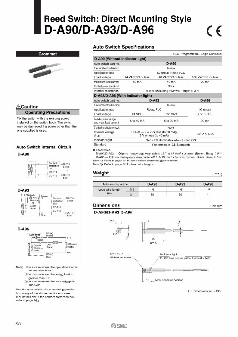
Reed Switch: Direct Mounting StyleD-A90/D-A93/D-A96
Grommet
Note) q In a case where the operation load is an inductive load. w In a case where the wiring load is greater than 5 m. e In a case where the load voltage is 100 VAC.
Use the auto switch with a contact protection box in any of the above mentioned cases. (For details about the contact protection box, refer to page 56.)
Fix the switch with the existing screw installed on the switch body. The switch may be damaged if a screw other than the one supplied is used.
Operating PrecautionsCaution
Auto Switch Internal Circuit
D-A90
D-A93
D-A96
Ree
d sw
itch
Ree
d sw
itch
Ree
d sw
itch
LED diode
LED diode
Contact protection box
CD-P11
CD-P12
OUT ()Brown
OUT ()Blue
OUT (+)Brown
OUT (–)Blue
Contact protection box
CD-P11
CD-P12
Blue
Resistor
Zener diode
Brown
LED diode
Resistor
Reverse current prevention diode
OUTBlack
DC (+)Brown
DC (–)Blue
Load
(+)
(–)
DC powersupply
( ): dimensions for D-A93.
PLC: Programmable Logic Controller
Auto switch part no.
Lead wire length(m)
D-A90
6
30
0.5
3
D-A93
6
30
D-A96
8
41
Unit: g
Unit: mm
Weight
DimensionsD-A90/D-A93/D-A96
� Lead wires D-A90/D-A93 — Oilproof heavy-duty vinyl cable: ø2.7, 0.18 mm2 x 2 cores (Brown, Blue), 0.5 m D-A96 — Oilproof heavy-duty vinyl cable: ø2.7, 0.15 mm2 x 3 cores (Brown, Black, Blue), 0.5 mNote 1) Refer to page 56 for reed switch common specifications.Note 2) Refer to page 56 for lead wire lengths.
IC circuit, Relay, PLC
24 VAC/DC or less
50 mA
None
1 or less (including lead wire length of 3 m)
48 VAC/DC or less
40 mA
100 VAC/DC or less
20 mA
Relay, PLC
24 VDC
5 to 40 mA
None
D-A93 — 2.4 V or less (to 20 mA)/3 V or less (to 40 mA)
Red LED illuminates when turned ON.
Conforming to CE Standards
100 VAC
5 to 20 mA
IC circuit
4 to 8 VDC
20 mA
0.8 V or less
Auto switch part no.
Electrical entry direction
Applicable load
Load voltage
Maximum load current
Contact protection circuit
Internal resistance
D-A93/D-A96 (With indicator light)Auto switch part no.
Electrical entry direction
Applicable load
Load voltage
Indicator light
Standard
D-A90In-line
D-A96D-A93In-line
D-A90 (Without indicator light)
Auto Switch Specifications
Load current rangeand max. load current
Internal voltage drop
Contact protection circuit
ø2.
722.8
4.5
4
22(24.5)
10
Indicator lightD-A90 type comes without indicator light.
Most sensitive position
M2.5 x 4 lSlotted set screw
58

SMC
14.3
6.5
ø4
33
13
15 129.
5
15.5
6.5
Indicator lightD-B64 type comes without indicator light.
Most sensitive positionø4.5
Grommet
Reed Switch: Band Mounting StyleD-B54/D-B64
Auto Switch Internal Circuit
D-B64
D-B54
Zener diode
Reedswitch
LEDdiode
Resistor
Choke coil
Surge absorber
OUT (–)Blue
Reed switch
Choke coil
Surge absorber
OUT ( )Blue
OUT (+)Brown
OUT ()Brown
Dimensions
PLC: Programmable Logic Controller
D-B5 (With indicator light)
D-B6 (Without indicator light)Auto switch part no.
Applicable load
Load voltage
Maximum load current
Contact protection circuit
Internal resistance
Standard
Auto switch part no.
Applicable load
Load voltage
Load current range Note 3)
Contact protection circuit
Internal voltage drop
Indicator light Red LED illuminates when turned ON.
D-B54
Relay, PLC
24 VDC
5 to 50 mA
100 VAC
5 to 25 mA
200 VAC
5 to 12.5 mA
Built-in
2.4 V or less (to 20 mA)/3.5 V or less (to 50 mA)
D-B64
Relay, PLC
24 VAC/DC or less
Max. 50 mA
100 VAC
Max. 25 mA
200 VAC
Max. 12.5 mA
Built-in
25 or less
Conforming to CE Standards
Weight
Auto switch part no.
0.5
3
5
22
78
126
22
78
—
D-B54 D-B64
Unit: g
Unit: mm
Lead wire length(m)
Auto Switch Specifications
� Lead wires — Oilproof heavy-duty vinyl cable: ø4, 0.3 mm2 x 2 cores (Brown, Blue), 0.5 mNote 1) Refer to page 56 for reed switch common specifications.Note 2) Refer to page 56 for lead wire lengths.Note 3) Under 5 mA, the strength of the indicator light is poor. In some cases, visibility of the
indicator light will not be possible where the output signal is less than 2.5 mA. However, there is no problem in terms of contact output, when an output signal exceeds 1 mA or more.
59

Connector
Indicator lightD-C80C type comes without indicator light.
Most sensitive position
Lead wire with connector
Reed Switch: Band Mounting StyleD-C73C/D-C80C
Weight
Dimensions
Auto switch part no.
0.5
3
5
14
53
83
14
53
83
D-C73C D-C80C
Unit: g
Unit: mm
Lead wire length(m)
D-C73C (With indicator light)Auto switch part no.
Applicable load
Load voltage
Load current range Note 4)
Contact protection circuit
Internal voltage drop
Indicator light
D-C73C
Relay, PLC
24 VDC
5 to 40 mA
None
2.4 V or less
Red LED illuminates when turned ON.
D-C80C (Without indicator light)Auto switch part no.
Applicable load
Load voltage
Maximum load current
Contact protection circuit
Internal resistance
Standard
D-C80CRelay, PLC
24 VAC/DC or less
50 mA
None
1 or less (including lead wire length of 3 m)
Conforming to CE Standards
� Lead wires — Oilproof heavy-duty vinyl cable: ø3.4, 0.2 mm2 x 2 cores (Brown, Blue), 0.5 mNote 1) Refer to page 56 for reed switch common specifications.Note 2) Refer to page 56 for lead wire lengths.Note 3) Lead wire with connector may be shipped with switch.Note 4) Under 5 mA, the strength of the indicator light is poor. In some cases, visibility of the
indicator light will not be possible where the output signal is less than 2.5 mA. However, there is no problem in terms of contact output, when an output signal exceeds 1 mA or more.
PLC: Programmable Logic Controller
Auto Switch Specifications
Auto Switch Internal CircuitD-C73C
D-C80C
Blue
Resistor
Zener diode
BrownOUT (+)Brown
OUT (–)Blue
Choke coil
Contact protection box
CD-P12
Zener diode
Contact protection box
CD-P11
CD-P12
OUT ()Brown
OUT ( )Blue
Note) q In a case where the operation load is an inductive load. w In a case where the wiring load is greater than 5 m.
Use the contact protection box in any of the above listed situations. The contact point life may decrease. (Refer to page 56 for contact protection box.)
1.Confirm that the connector is appropri-ately tightened. If tightened insuffi-ciently, the waterproof performance will deteriorate.
2. For how to handle a connector, refer to “Best Pneumatics 2004” Vol. 8 catalog.
Operating PrecautionsCaution
Ree
d sw
itch
Ree
d sw
itch
LED diode
60
Indicator light
Most sensitive position
Auto Switch Internal Circuit
Choke coil
Zener diode
Reed switch
LED
OUT (+)Brown
OUT (–)Blue
Switc
h m
ain
circ
uit
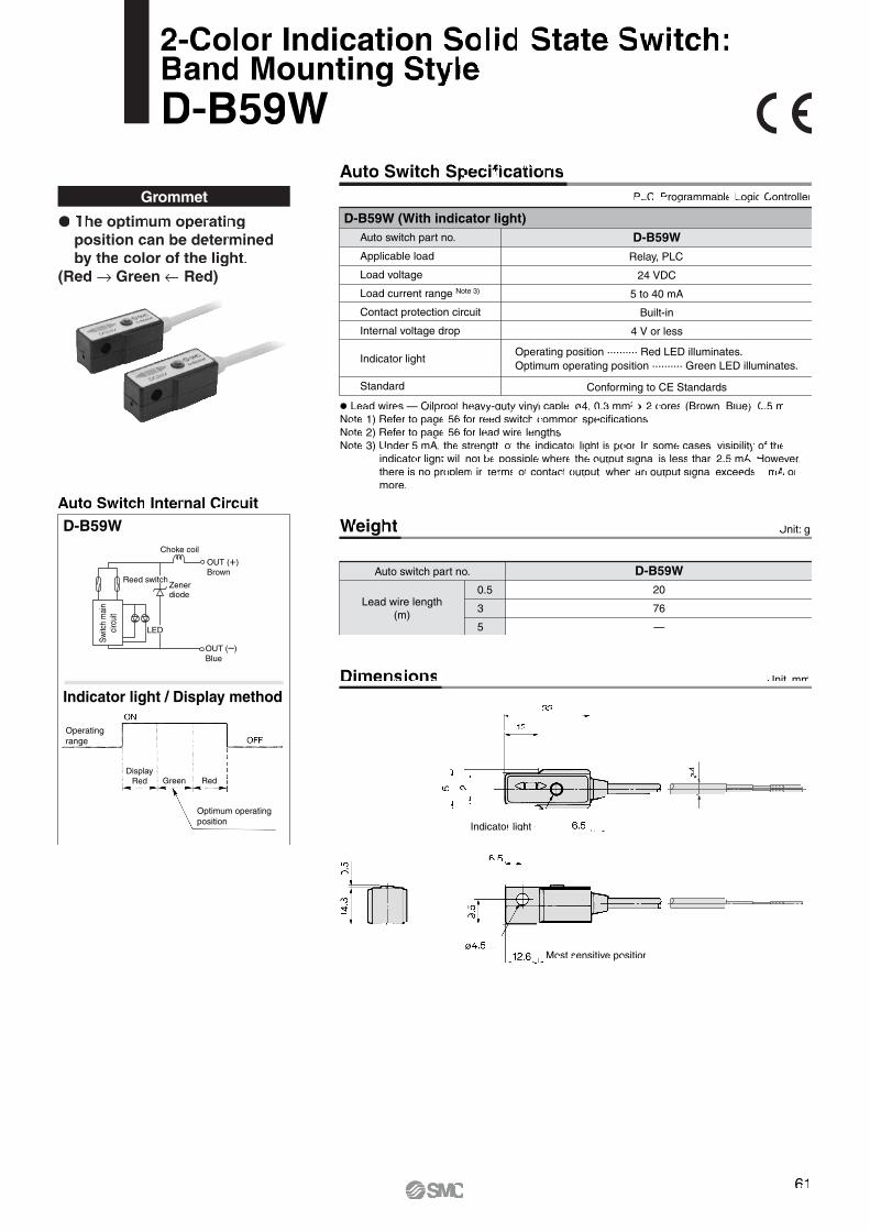
D-B59W
Grommet
� The optimum operating position can be determined by the color of the light.
(Red → Green ← Red)
Indicator light / Display method
Operatingrange
Optimum operatingposition
DisplayRed Green Red
2-Color Indication Solid State Switch: Band Mounting StyleD-B59W
Unit: g
Auto switch part no.
0.5
3
5
20
76
—
D-B59W
Lead wire length(m)
D-B59W (With indicator light)Auto switch part no.
Applicable load
Load voltage
Load current range Note 3)
Contact protection circuit
Internal voltage drop
Standard
Indicator light
D-B59W
Relay, PLC
24 VDC
5 to 40 mA
Built-in
4 V or less
Conforming to CE Standards
� Lead wires — Oilproof heavy-duty vinyl cable: ø4, 0.3 mm2 x 2 cores (Brown, Blue), 0.5 mNote 1) Refer to page 56 for reed switch common specifications.Note 2) Refer to page 56 for lead wire lengths.Note 3) Under 5 mA, the strength of the indicator light is poor. In some cases, visibility of the
indicator light will not be possible where the output signal is less than 2.5 mA. However, there is no problem in terms of contact output, when an output signal exceeds 1 mA or more.
Operating position .......... Red LED illuminates.Optimum operating position .......... Green LED illuminates.
Weight
Unit: mmDimensions
PLC: Programmable Logic Controller
Auto Switch Specifications
ø4
61
Grommet
Slotted set screw
Mounting screw M2.5 x 4 l
Indicator light
2.7
22
22
2.6
4
2.8
3.2
6 Most sensitive position
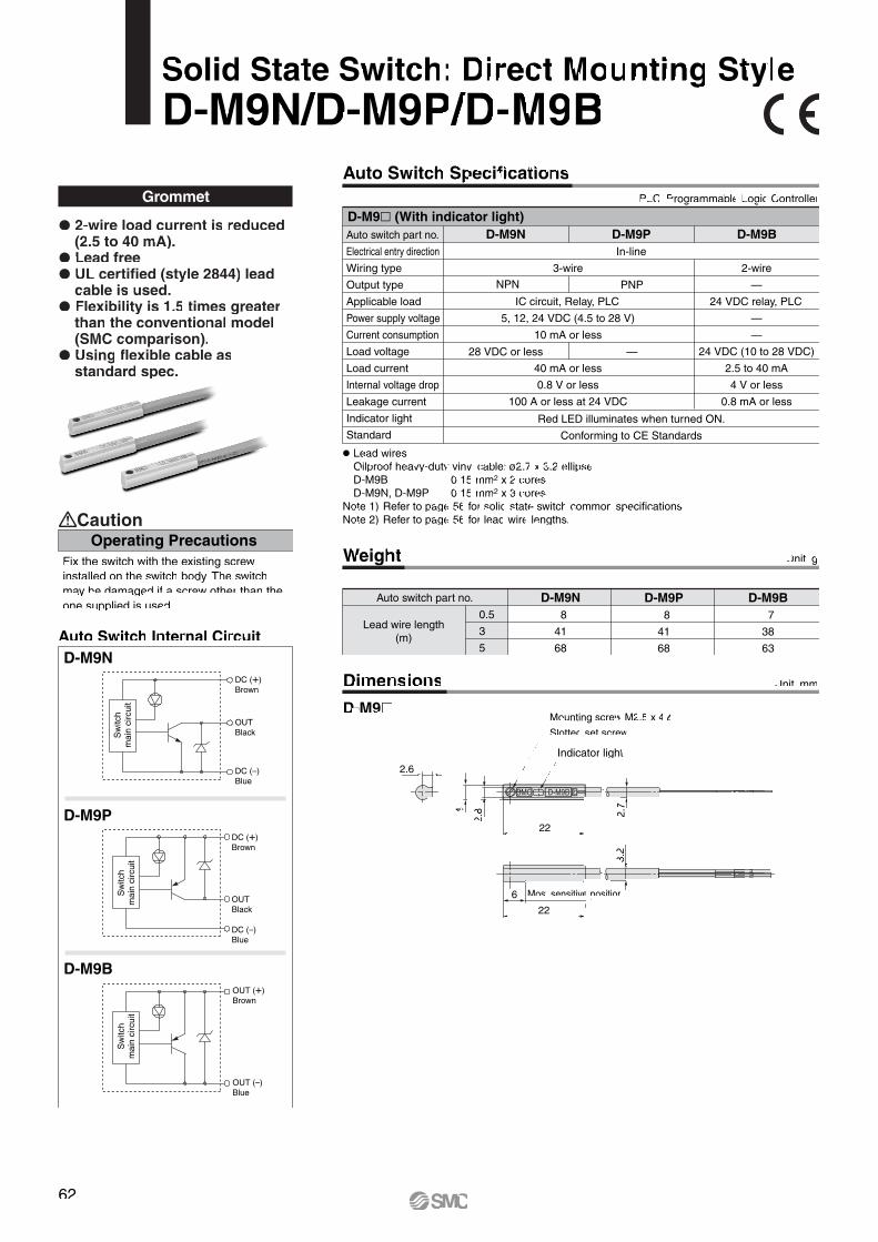
� 2-wire load current is reduced (2.5 to 40 mA).
� Lead free� UL certified (style 2844) lead
cable is used.� Flexibility is 1.5 times greater
than the conventional model (SMC comparison).
� Using flexible cable as standard spec.
Solid State Switch: Direct Mounting StyleD-M9N/D-M9P/D-M9B
Weight
Auto switch part no.
0.5
3
5
D-M9N 8
41
68
D-M9P 8
41
68
D-M9B 7
38
63
Unit: g
Lead wire length(m)
Auto switch part no.
Electrical entry direction
Wiring type
Output type
Applicable load
Power supply voltage
Current consumption
Load voltage
Load current
Internal voltage drop
Leakage current
Indicator light
Standard
D-M9N D-M9B
2-wire
—
24 VDC relay, PLC
—
—
24 VDC (10 to 28 VDC)
2.5 to 40 mA
4 V or less
0.8 mA or less
D-M9P
Red LED illuminates when turned ON.
Conforming to CE Standards
3-wire
IC circuit, Relay, PLC
5, 12, 24 VDC (4.5 to 28 V)
10 mA or less
40 mA or less
0.8 V or less
100 A or less at 24 VDC
In-line
NPN PNP
28 VDC or less —
D-M9� (With indicator light)
� Lead wires Oilproof heavy-duty vinyl cable: ø2.7 x 3.2 ellipse D-M9B 0.15 mm2 x 2 cores D-M9N, D-M9P 0.15 mm2 x 3 coresNote 1) Refer to page 56 for solid state switch common specifications.Note 2) Refer to page 56 for lead wire lengths.
Dimensions
D-M9�
Unit: mm
PLC: Programmable Logic Controller
Auto Switch Specifications
Auto Switch Internal CircuitD-M9N
D-M9B
D-M9P
Operating PrecautionsCaution
Fix the switch with the existing screw installed on the switch body. The switch may be damaged if a screw other than the one supplied is used.
Sw
itch
mai
n ci
rcui
tS
witc
h m
ain
circ
uit
Sw
itch
mai
n ci
rcui
t
OUTBlack
DC (+)Brown
DC (–)Blue
OUTBlack
DC (+)Brown
DC (–)Blue
OUT (+)Brown
OUT (–)Blue
62

63
Auto Switch Internal Circuit
D-G59
D-K59
D-G5P
Weight
Dimensions
Auto switch part no.
0.5
3
5
20
78
124
20
78
124
18
68
108
D-G59 D-G5P D-K59
Unit: g
Unit: mm
Grommet
Lead wire length(m)
D-G5�/D-K59 (With indicator light)Auto switch part no.
Wiring type
Output type
Applicable load
Power supply voltage
Current consumption
Load voltage
Load current
Internal voltage drop
Leakage current
Indicator light
Standard
D-G59
NPN
28 VDC or less
40 mA or less1.5 V or less
(0.8 V or less atload current 10 mA)
D-G5P
PNP
—
80 mA or less
0.8 V or less
Red LED illuminates when turned ON.
Conforming to CE Standards
D-K592-wire
—
24 VDC relay, PLC
—
—
24 VDC (10 to 28 VDC)
5 to 40 mA
4 V or less
0.8 mA or less at 24 VDC
� Lead wires — Oilproof heavy-duty vinyl cable: ø4, 0.3 mm2 x 3 cores (Brown, Black, Blue), 2 cores (Brown, Blue), 0.5 mNote 1) Refer to page 56 for solid state switch common specifications.Note 2) Refer to page 56 for lead wire lengths.
3-wire
IC circuit, Relay, PLC
5, 12, 24 VDC (4.5 to 28 V)
10 mA or less
100 A or less at 24 VDC
Solid State Switch: Band Mounting StyleD-G59/D-G5P/D-K59
PLC: Programmable Logic Controller
Auto Switch Specifications
ø4.5 Mounting hole
Most sensitive position
Indicator light
Sw
itch
mai
n ci
rcui
tS
witc
h m
ain
circ
uit
Sw
itch
mai
n ci
rcui
t
OUTBlack
DC (+)Brown
DC (–)Blue
OUTBlack
DC (+)Brown
DC (–)Blue
OUT (+)Brown
OUT (–)Blue

Auto Switch Internal CircuitD-G59
Auto switch part no.
0.5
3
5
15
54
85
D-H7C
Unit: g
Solid State Switch: Band Mounting StyleD-H7C
Connector
Lead wire length(m)
D-H7C (With indicator light)Auto switch part no.
Wiring type
Output type
Applicable load
Power supply voltage
Current consumption
Load voltage
Load current
Internal voltage drop
Leakage current
Indicator light
Standard
D-H7C
2-wire
—
24 VDC Relay, PLC
—
—
24 VDC (10 to 28 VDC)
5 to 40 mA
4 V or less
0.8 mA or less at 24 VDC
Red LED illuminates when turned ON.
Conforming to CE Standards
� Lead wires — Oilproof heavy-duty vinyl cable: ø3.4, 0.2 mm2 x 2 cores (Brown, Blue), 0.5 mNote 1) Refer to page 56 for solid state switch common specifications.Note 2) Refer to page 56 for lead wire lengths and lead wire with connector.
1.Confirm that the connector is appropri-ately tightened. If tightened insuffi-ciently, the waterproof performance will deteriorate.
2. For how to handle a connector, refer to “Best Pneumatics 2004” Vol. 8 catalog.
Operating PrecautionsCaution
Weight
Unit: mmDimensions
PLC: Programmable Logic Controller
Auto Switch Specifications
ø3.5 Mounting hole
Most sensitive position
Indicator light
OUT (+)Brown
OUT (–)Blue
Sw
itch
mai
n ci
rcui
t
64

Unit: mmDimensions
Auto switch part no.
Electrical entry direction
Wiring type
Output type
Applicable load
Power supply voltage
Current consumption
Load voltage
Load current
Internal voltage drop
Leakage current
Indicator light
Standard
D-M9NW D-M9BW
2-wire
—
24 VDC relay, PLC
—
—
24 VDC (10 to 28 VDC)
2.5 to 40 mA
4 V or less
0.8 mA or less
D-M9PW
Operating position .......... Red LED illuminates.Optimum operating position .......... Green LED illuminates.
3-wire
IC circuit, Relay, PLC
5, 12, 24 VDC (4.5 to 28 V)
10 mA or less
40 mA or less
0.8 V or less at 10 mA (2 V or less at 40 mA)
100 A or less at 24 VDC
Conforming to CE Standards
In-line
NPN PNP
28 VDC or less —
D-M9�W (With indicator light)
� Lead wires Oilproof heavy-duty vinyl cable: ø2.7 x 3.2 ellipse D-M9BW 0.15 mm2 x 2 cores D-M9NW, D-M9PW 0.15 mm2 x 3 coresNote 1) Refer to page 56 for solid state switch common specifications.Note 2) Refer to page 56 for lead wire lengths.
D-M9�W Mounting screw M2.5 x 4 lSlotted set screw
Indicator light
2.7
22
22
2.6
4
2.8
3.2
6 Most sensitive position
Grommet
� 2-wire load current is reduced (2.5 to 40 mA).
� UL certified (style 2844) lead cable is used.
� The optimum operating position can be determined by the color of the light. (Red → Green → Red)
D-M9NW
D-M9BW
D-M9PW
Indicator light / Display method
Auto Switch Internal Circuit
Weight Unit: g
Auto switch part no.
0.5
1
3
5
D-M9NW8
14
41
68
D-M9PW8
14
41
68
D-M9BW7
13
38
63
Lead wire length(m)
2-Color Indication Solid State Switch: Direct Mounting StyleD-M9NW/D-M9PW/D-M9BW
PLC: Programmable Logic Controller
Auto Switch Specifications
OUTBlack
DC (+)Brown
DC (–)Blue
DC (+)Brown
OUTBlack
DC (–)Blue
OUT (+)Brown
OUT (–)Blue
ON
OFFOperatingrange
Sw
itch
mai
n ci
rcui
tS
witc
h m
ain
circ
uit
Sw
itch
mai
n ci
rcui
t
Optimum operatingposition
DisplayRed Green Red
65
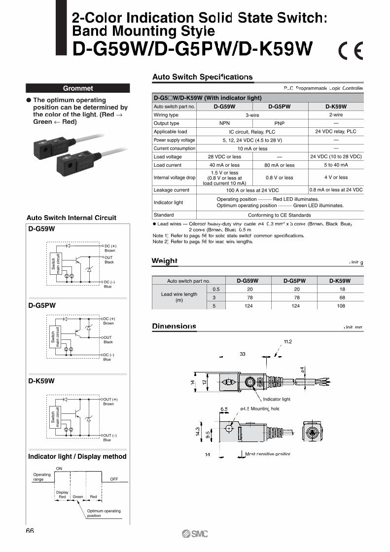
66
Weight
Dimensions
Unit: g
Unit: mm
Auto switch part no.
0.5
3
5
20
78
124
20
78
124
18
68
108
D-G59W D-G5PW D-K59W
Lead wire length(m)
Auto Switch Internal Circuit
D-G59W
D-K59W
Indicator light / Display method
D-G5PW
GrommetD-G5�W/D-K59W (With indicator light)
D-G59W D-K59W2-wire
—
24 VDC relay, PLC
—
—
24 VDC (10 to 28 VDC)
5 to 40 mA
4 V or less
0.8 mA or less at 24 VDC
D-G5PW
PNP
—
80 mA or less
0.8 V or less
Conforming to CE Standards
� Lead wires — Oilproof heavy-duty vinyl cable: ø4, 0.3 mm2 x 3 cores (Brown, Black, Blue), 2 cores (Brown, Blue), 0.5 mNote 1) Refer to page 56 for solid state switch common specifications.Note 2) Refer to page 56 for lead wire lengths.
1.5 V or less(0.8 V or less at
load current 10 mA)
Auto switch part no.
Wiring type
Output type
Applicable load
Power supply voltage
Current consumption
Load voltage
Load current
Internal voltage drop
Leakage current
Indicator light
Standard
2-Color Indication Solid State Switch: Band Mounting StyleD-G59W/D-G5PW/D-K59W
PLC: Programmable Logic Controller
Auto Switch Specifications
3-wire
IC circuit, Relay, PLC
5, 12, 24 VDC (4.5 to 28 V)
10 mA or less
100 A or less at 24 VDC
NPN
28 VDC or less
40 mA or less
Operating position .......... Red LED illuminates.Optimum operating position .......... Green LED illuminates.
ø4.5 Mounting hole
Indicator light
Most sensitive position
� The optimum operating position can be determined by the color of the light. (Red → Green ← Red)
OUTBlack
DC (+)Brown
DC (–)Blue
DC (+)Brown
OUTBlack
DC (–)Blue
OUT (+)Brown
OUT (–)Blue
ON
OFFOperatingrange
Sw
itch
mai
n ci
rcui
tS
witc
h m
ain
circ
uit
Sw
itch
mai
n ci
rcui
t
Optimum operatingposition
DisplayRed Green Red

Auto Switch Internal Circuit
Grommet
ø3.
4
� Water (coolant) resistant type� The optimum operating
position can be determined by the color of the light.
(Red → Green → Red)
� Lead wires — Oilproof heavy-duty vinyl cable: ø3, ø4, 0.2 mm2 x 2 cores (Brown, Blue), 3 m (Standard)Note 1) Refer to page 56 for solid state switch common specifications.Note 2) Refer to page 56 for lead wire lengths.
D-H7BAL (With indicator light)Auto switch part no.
Wiring type
Output type
Applicable load
Power supply voltage
Current consumption
Load voltage
Load current
Internal voltage drop
Leakage current
Indicator light
Standard
D-H7BAL
2-wire
—
24 VDC Relay, PLC
—
—
24 VDC (10 to 28 VDC)
5 to 40 mA
4 V or less
0.8 mA or less at 24 VDC
Conforming to CE Standards
Operating position .......... Red LED illuminates.Optimum operating position .......... Green LED illuminates.
Operating PrecautionsCaution
Please consult SMC if using coolant liquid other than water based solution.
ON
OFFOperatingrange
Optimum operatingposition
DisplayRed Green Red
Indicator light / Display methodø3.5 Mounting hole
Auto switch part no.
0.5
3
5
Unit: g
Lead wire length(m)
D-H7BA—
50
81
Weight
Unit: mmDimensions
Water Resistant 2-Color Indication Solid State Switch: Band Mounting StyleD-H7BAL
PLC: Programmable Logic Controller
Auto Switch Specifications
Indicator light
Most sensitive position
OUT (+)Brown
OUT (–)Blue
Sw
itch
mai
n ci
rcui
t
67
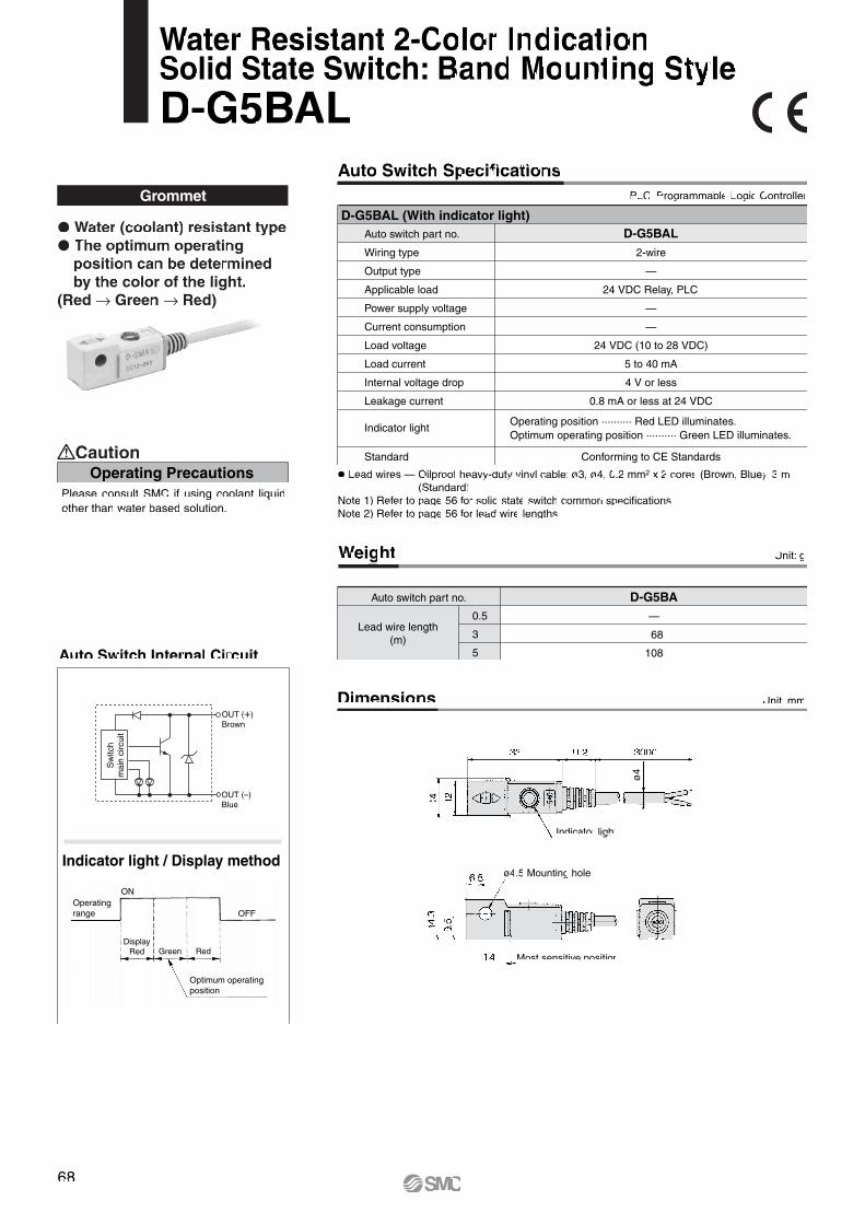
68
Auto Switch Internal Circuit
Dimensions
Grommet
ø4
Weight
Auto switch part no.
0.5
3
5
D-G5BA—
68
108
Unit: g
Lead wire length(m)
� Water (coolant) resistant type� The optimum operating
position can be determined by the color of the light.
(Red → Green → Red)
� Lead wires — Oilproof heavy-duty vinyl cable: ø3, ø4, 0.2 mm2 x 2 cores (Brown, Blue), 3 m (Standard)Note 1) Refer to page 56 for solid state switch common specifications.Note 2) Refer to page 56 for lead wire lengths.
D-G5BAL (With indicator light)Auto switch part no.
Wiring type
Output type
Applicable load
Power supply voltage
Current consumption
Load voltage
Load current
Internal voltage drop
Leakage current
Indicator light
Standard
D-G5BAL
2-wire
—
24 VDC Relay, PLC
—
—
24 VDC (10 to 28 VDC)
5 to 40 mA
4 V or less
0.8 mA or less at 24 VDC
Conforming to CE Standards
Operating position .......... Red LED illuminates.Optimum operating position .......... Green LED illuminates.
Indicator light / Display methodø4.5 Mounting hole
Unit: mm
Water Resistant 2-Color Indication Solid State Switch: Band Mounting StyleD-G5BAL
PLC: Programmable Logic Controller
Auto Switch Specifications
Indicator light
Most sensitive position
Operating PrecautionsCaution
Please consult SMC if using coolant liquid other than water based solution.
ON
OFFOperatingrange
Optimum operatingposition
DisplayRed Green Red
OUT (+)Brown
OUT (–)Blue
Sw
itch
mai
n ci
rcui
t

Indicator light
Red Green Red Red
OUT(Normal output)
Diagnosis OUT(Diagnostic output)
Auto Switch Internal Circuit
Diagnostic Output Operation
Dimensions
ø3.5 Mounting hole
Indicator light
Most sensitive position
ø3.
4
D-H7NF (With indicator light)Auto switch part no.
Wiring type
Output type
Diagnostic output type
Applicable load
Power supply voltage
Current consumption
Load voltage
Load current
Internal voltage drop
Leakage current
Indicator light
Standard
D-H7NF
4-wire
NPN
Normal operation
IC circuit, Relay, PLC
5, 12, 24 VDC (4.5 to 28 VDC)
10 mA or less
28 VDC or less
50 mA or less at the total amount of normal output and diagnostic output
1.5 V or less (0.8 V or less at 5 mA)
100 A or less at 24 VDC
Conforming to CE Standards
Operating position .......... Red LED illuminates.Optimum operating position .......... Green LED illuminates.
Weight Unit: g
Unit: mm
Auto switch part no.
0.5
3
5
13
56
90
D-H7NF
Lead wire length(m)
Grommet
� Lead wires — Oilproof heavy-duty vinyl cable: ø3.4, 0.2 mm2 x 4 cores (Brown, Black, Orange, Blue), 0.5 mNote 1) Refer to page 56 for solid state switch common specifications.Note 2) Refer to page 56 for lead wire lengths.
2-Color Indication with Diagnostic Output Solid State Switch: Band Mounting StyleD-H7NF
PLC: Programmable Logic Controller
Auto Switch Specifications
The diagnostic signal is output within unsteady detecting area (where indicator light is Red), and the diagnostic output becomes OFF when the detecting position remains within the optimum operating position (where indicator is Green). When the detecting position is not adjusted, the diagnostic output becomes ON.
� Since the output signal can be detected in an unsteady detecting area, the difference of detecting position can be confirmed by the side of PLC (Programmable Logic Controller).
� The optimum operating position can be determined by the color of the light.
(Red → Green → Red)
OUT (Normal output)Black
DC (+)Brown
DC (–)Blue
Diagnosis OUT(Diagnostic output)OrangeS
witc
h m
ain
circ
uit
69

70
ø4
Dimensions
D-G59F (With indicator light)Auto switch part no.
Wiring type
Output type
Diagnostic output type
Applicable load
Power supply voltage
Current consumption
Load voltage
Load current
Internal voltage drop
Leakage current
Indicator light
Standard
D-G59F
4-wire
NPN
Normal operation
IC circuit, Relay, PLC
5, 12, 24 VDC (4.5 to 28 VDC)
10 mA or less
28 VDC or less
50 mA or less at the total amount of normal output and diagnostic output
1.5 V or less (0.8 V or less at 5 mA)
100 A or less at 24 VDC
Conforming to CE Standards
Operating position .......... Red LED illuminates.Optimum operating position .......... Green LED illuminates.
� Lead wires — Oilproof heavy-duty vinyl cable: ø4, 0.2 mm2 x 4 cores (Brown, Black, Orange, Blue), 0.5 mNote 1) Refer to page 56 for solid state switch common specifications.Note 2) Refer to page 56 for lead wire lengths.
ø4.5 Mounting hole
Unit: mm
2-Color Indication with Diagnostic Output Solid State Switch: Band Mounting StyleD-G59F
PLC: Programmable Logic Controller
Auto Switch SpecificationsGrommet
� Since the output signal can be detected in an unsteady detecting area, the difference of detecting position can be confirmed by the side of PLC (Programmable Logic Controller).
� The optimum operating position can be determined by the color of the light.
(Red → Green → Red)
Auto Switch Internal Circuit
OUT (Normal output)Black
DC (+)Brown
DC (–)Blue
Diagnosis OUT(Diagnostic output)OrangeS
witc
h m
ain
circ
uit
Weight
Auto switch part no.
0.5
3
5
20
74
117
D-G59F
Unit: g
Lead wire length(m)
Diagnostic Output Operation
Indicator light
Red Green Red Red
OUT(Normal output)
Diagnosis OUT(Diagnostic output)
The diagnostic signal is output within unsteady detecting area (where indicator light is Red), and the diagnostic output becomes OFF when the detecting position remains within the optimum operating position (where indicator is Green). When the detecting position is not adjusted, the diagnostic output becomes ON.
Indicator light
Most sensitive position

It adjusts the extending stroke by the stroke adjustable mechanism equipped in the head side. (After the stroke is adjusted, with cushion on both sides is altered to single-sided, with cushion.)
5 Adjustable Stroke Cylinder / Adjustable Extension Type XC8Symbol
How to Order
MGG
MGC Stroke adjust-ment symbol
With/Withoutrear plate XC8
Adjustable stroke cylinder / Adjustable extension type
Bearing Mounting Bore size Port thread Stroke
Bearing Mounting Bore size Port thread Stroke
Stroke adjustment symbol Auto switch
Auto switch
XC8
Stroke adjustmentrange (mm)
SpecificationsStroke
adjustment symbol
A
B
0 to 25
0 to 50
Applicableseries
MGGMGC
Note) Specifications other than above are the same as standard type of each series.
Precautions1. When the cylinder is operating, if something gets caught
between the stopper bracket for adjusting the stroke and the cylinder body, it could injure personnel or damage the periph-eral equipment. Therefore, take preventive measures as necessary, such as installing a protective cover.
2. To adjust the stroke, make sure to secure the wrench flats of the stopper bracket before loosening the nut. If the nut is loosened without securing the stopper bracket, be aware that the area that joins the load to the piston rod or the area in which the piston rod is joined with the load side and the stopper bracket side could loosen first.
Warning
(mm)
Bore size(mm) R
202532405063
12
12
12
13
14
14
Y
77
77
79
87
102
117
MA
14
17
17
24
32
32
MD
8
10
12
16
20
20
MI
16.2
19.7
19.7
27.8
37
37
MT
9
11
11
11
11
13
MM
M8 x 1.25
M10 x 1.25
M10 x 1.25
M14 x 1.5
M18 x 1.5
M18 x 1.5
Adjustment 0 to 25 mm Adjustment 0 to 50 mm
MH63
66
66
72
85
85
ML43
43
43
47
53
53
ZZ179
189
191
215
254
256
MH 88
91
91
97
110
110
ML68
68
68
72
78
78
ZZ204
214
216
240
279
281
Bore size(mm)
202532405063
(mm)
12
12
12
13
14
R
86
86
88
99
114
Y
14
17
17
24
32
MA
8
10
12
16
20
MD
16.2
19.7
19.7
27.8
37
MI
M8 x 1.25
M10 x 1.25
M10 x 1.25
M14 x 1.5
M18 x 1.5
MM
9
11
11
11
11
MTBore size(mm)
2025324050
Bore size(mm)
2025324050
Adjustment 0 to 25 mm Adjustment 0 to 50 mm
63
66
66
72
85
MH43
43
43
47
53
ML179
189
191
215
254
ZZ 88
91
91
97
110
MH68
68
68
72
78
ML204
214
216
240
279
ZZ
Series MGGø20 to ø50
Series MGCø20 to ø50
ø63
Dimensions (Dimensions other than below are the same as standard type.)
Front mounting flange
øM
D
MM
Width across flats MA
MH + Stroke
Stroke
Y + Stroke
ZZ + 2 strokes
ML
R
(MI)
MT
Front mounting flange
Y + Stroke MH + Stroke
ZZ + 2 strokes
Stroke MLMT
øM
D
R
MM
Width across flats MA
(MI)
JIS Symbol
Front mounting flange
MM
Width across flats MA
Stroke MLMTY + Stroke MH + Stroke
ZZ + 2 strokes
R
(MI)
øM
D
∗ Piston speed of the extension side is 50 to 500 mm/s.
∗ Piston speed of the extension side is 50 to 500 mm/s.
Series MGG
Series MGC
Adjustablerange
75
Series MGG/MGCMade to Order 3Please contact SMC for detailed specifications, lead times, and prices.
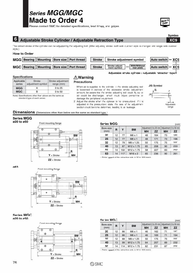
The retract stroke of the cylinder can be adjusted by the adjusting bolt. (After adjusting stroke, both-side cushion style is changed into single side cushion style.)
6 Adjustable Stroke Cylinder / Adjustable Retraction Type XC9Symbol
Stroke adjustmentrange (mm)
SpecificationsStroke
adjustment symbol
A
B
0 to 25
0 to 50
Applicableseries
MGGMGC
Note) Specifications other than above are the same as standard type of each series.
Precautions1. When air is supplied to the cylinder, if the stroke adjusting bolt
is loosened in excess of the allowable stroke adjustment amount, be aware that the stroke adjusting bolt could fly out or air could be discharged, which could injure personnel or damage the peripheral equipment.
2. Adjust the stroke when the cylinder is not pressurized. If it is adjusted in the pressurized state, the seal of he adjustment section could become deformed, leading to air leakage.
Warning
Series MGGø20 to ø50
Series MGCø20 to ø50
ø63
Dimensions (Dimensions other than below are the same as standard type.)
JIS Symbol
(mm)
Adjustment 0 to 25 mm
MH48
48
50
65
58
65
12
12
12
13
14
14
RZZ164
171
175
208
227
236
Adjustment 0 to 50 mm
MH73
73
75
90
83
90
ZZ189
196
200
233
252
261
77
77
79
87
102
117
Y
M6 x 1
M6 x 1
M8 x 1.25
M12 x 1.75
M12 x 1.75
M16 x 2
BMBore size(mm)
202532405063
∗ Piston speed of the retraction side is 50 to 500 mm/s.
∗ Piston speed of the retraction side is 50 to 500 mm/s.
(mm)
Bore size(mm)
2025324050
Adjustment 0 to 25 mm Adjustment 0 to 50 mm
46
46
50
64
62
MH12
12
12
13
14
R
162
169
175
207
231
ZZ71
71
75
89
87
MH187
194
200
232
256
ZZ 86
86
88
99
114
Y
M6 x 1
M6 x 1
M8 x 1.25
M12 x 1.75
M12 x 1.75
BM
Front mounting flange
Y + Stroke
ZZ + Stroke
R
MH
BM
Front mounting flange
Y + Stroke
ZZ + Stroke
MH
R
BM
Front mounting flange
Y + Stroke
ZZ + Stroke
R
MH
BM
How to Order
Series MGG
Series MGC
Adjustablerange
MGG
MGC Stroke adjust-ment symbol
With/Withoutrear plate XC9
Adjustable stroke cylinder / Adjustable retraction type
Bearing Mounting Bore size Port thread Stroke
Bearing Mounting Bore size Port thread Stroke
Stroke adjustment symbol Auto switch
Auto switch
XC9
76
Series MGG/MGCMade to Order 4Please contact SMC for detailed specifications, lead times, and prices.