guru nanak dev thermal power
TRANSCRIPT
8/9/2019 Guru Nanak Dev Thermal Power
http://slidepdf.com/reader/full/guru-nanak-dev-thermal-power 1/120
Guru Nanak Dev Thermal Power Plant is a coal-based plant. The requirement of
coal for four units based on specific fuel consumption of 0.60 k ! k"h. The conve#in
and crushin s#stem will have the same capacit# as that of the unloadin s#stem. The
coal comes in as lare pieces. This coal is fed to primar# crushers$ which reduce the si%e
of coal pieces from &00mm to '(0mm. Then the coal is sent to secondar# crusher throuh
forward conve#ors where it is crushed from '(0mm to )00mm as required at the mills.
Then the coal is sent to boilers with the help of primar# fans. The coal is burnt in the
boiler. *oiler includes the pipes carr#in water throuh them+ heat produced from the
combustion of coal is used to convert water in pipes into steam. This steam enerated is
used to run the turbine. "hen turbine rotates$ the shaft of enerator$ which is
mechanicall# coupled to the shaft of turbine$ ets rotated so$ three phase electric suppl# is
produced.
The basic requirements are,-
uel /coal
*oiler
1team turbine
Generator
2sh handlin s#stem
3nit au4iliaries
'
INTRODUCTIO
N
8/9/2019 Guru Nanak Dev Thermal Power
http://slidepdf.com/reader/full/guru-nanak-dev-thermal-power 2/120
Due to hih rate of increasin population da# b# da#$ widenin ap between power
demand and its availabilit# was one the basic reason for envisain the G.N.D.T.P.
for the state of Pun5ab. The other factors favorin the installation of the thermal
power station were low initial cost and comparativel# less estation period as
compared to h#dro electric eneratin stations. The foundation stone of G.N.D.T.P.
at bathinda was laid on '
th
November '6$ the auspicious occasion of (00
th
birth
anniversar# of reat Guru Nanak Dev 7i.
The historic town of bathinda was selected for this first and prestiious thermal
pro5ect of the state due to its ood railwa# connections for fast transportations of coal$
availabilit# of canal water and pro4imit# to load center.
The total installed capacit# of the power station &&08" with four units of
''08" each. The first unit of the plant was commissioned in 1eptember$ '9&.
1ubsequentl# second$ third and fourth units started eneration in 1eptember '9($ 8arch
'9:$ 7anuar# '9 respectivel#. The power available from this plant ives spin to the
wheels of industr# and aricultural pumpin sets.
)
BRIEF HISTORY
OF
PLANT
8/9/2019 Guru Nanak Dev Thermal Power
http://slidepdf.com/reader/full/guru-nanak-dev-thermal-power 3/120
;<8 of GNDTP unit '<) has alread# been completed pendin PG Test. ;<8 works of
unit =<& is underwa# to improve performance$ enhance capacit# and e4tend operatin
life of the units. The present status of ;<8 works of GNDTP units is as under,
3nit ><>>, - 2ainst approved pro5ect ;eport of ;s. )) ?rores$ @rder was placed on 8!1
N21A$ New Delhi for ma5or ;<8 works on Turnke# basis at a total of ;s.':= ?rores.
3nit >>, ;<8 works completed in @ctober$ )00( /Pendin attendin to some deficiencies
b# the firm. 2verae PA achieved post ;<8 works is :9B.
3nit >, - ;<8 works completed and taken for normal operation in 8a#$ )009/Pendinattendin to some deficiencies b# the firm. 2verae PA achieved post ;<8 durin
8a#C09 and 7une C09 is (.6(B.
3nit >>> < >, - @rder for e4ecutin ;<8 works on Turnke# basis alread# placed on 8!1
*EFA at a total cost of ;s. &6(.=6 ?rores. '0B advance pa#ment has been made to 8!1
*EFA on ))!')!)006 and desin and drawin work is in proress. 2s per 1chedule$ work
is to be completed in a phased manner upto 7ul# )00. 2part from enhancin the
operatin life and performance level of the units$ it is also planned to uprade the
capacit# from ''0 8" to ')0 8" each resultin in total capacit# addition of )0 8".
=
SITE
SELECTION
R&M WORKS AT
GNDTP,
BATHINDA
8/9/2019 Guru Nanak Dev Thermal Power
http://slidepdf.com/reader/full/guru-nanak-dev-thermal-power 4/120
The selection of site for Thermal Power Plant is more difficult compared to E#dro
Power Plant$ as it involves number of factors to be considered for its economic
5ustification. The followin consideration should be e4amined in detail before selection
of the site for the Plant. The location for plant should be made with full consideration not
onl# of the trends in the development and location but also the availabilit# and location of
the cheapest source of primar# ener#,-
2vailabilit# of fuel
2sh disposal facilities
1pace requirement
Nature of land
2vailabilit# of labour
Transport facilities
Public societ# problems
Development of *ackward 2rea
&
8/9/2019 Guru Nanak Dev Thermal Power
http://slidepdf.com/reader/full/guru-nanak-dev-thermal-power 5/120
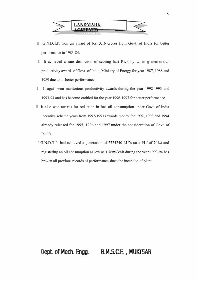
G.N.D.T.P. won an award of ;s. =.'6 crores from Govt. of >ndia for better
performance in ':=-:&.
>t achieved a rare distinction of scorin hart ;ick b# winnin meritorious
productivit# awards of Govt. of >ndia$ 8inistr# of Fner# for #ear ':9$ ':: and
': due to its better performance.
>t aain won meritorious productivit# awards durin the #ear ')-'= and
'=-& and has become entitled for the #ear '6-'9 for better performance.
>t also won awards for reduction in fuel oil consumption under Govt. of >ndia
incentive scheme #ears from ')-'= /awards mone# for ')$ '= and '&
alread# released for '($ '6 and '9 under the consideration of Govt. of
>ndia.
G.N.D.T.P. had achieved a eneration of )9)&)&0 A3Cs /at a PAf of 90B and
reisterin an oil consumption as low as '.96ml!kwh durin the #ear '=-& has
broken all previous records of performance since the inception of plant.
(
LANDMARK
ACHIEVED
8/9/2019 Guru Nanak Dev Thermal Power
http://slidepdf.com/reader/full/guru-nanak-dev-thermal-power 6/120
Guru Nanak Dev Thermal Plant$ *athinda$ in addition to indirect contribution in various
facts of state econom#$ is also responsible for,-
♣ Narrowin the ap between power demand and power availabilit# of the state.
♣ Providin emplo#ment potentials to thousands of workers.
♣ ?overin the backward surroundin area into full# developed >ndustrial
Township.
♣ Providin additional relief to aricultural pumpin sets to meet the irriation
needs for enhancin the ariculture production.
♣ ;eliabilit# and improvement in continuit# of suppl# and s#stem voltae.
♣ 2chievin cent percent rural electrification of the state.
6
CONTRIBUTION
OF
THE PLANT
8/9/2019 Guru Nanak Dev Thermal Power
http://slidepdf.com/reader/full/guru-nanak-dev-thermal-power 7/120
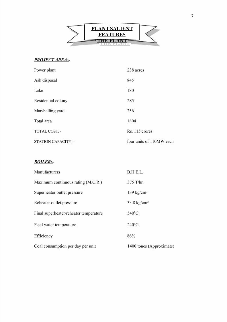
PROJECT AREA:-
Power plant )=: acres
2sh disposal :&(
Aake ':0
;esidential colon# ):(
8arshallin #ard )(6
Total area ':0&
T@T2A ?@1T, - ;s. ''( crores
1T2T>@N ?2P2?>T, - four units of ''08".each
BOILER:-
8anufacturers *.E.F.A.
8a4imum continuous ratin /8.?.;. =9( T!hr.
1uperheater outlet pressure '= k!cmH
;eheater outlet pressure ==.: k!cmH
inal superheater!reheater temperature (&0°?
eed water temperature )&0°?
Ffficienc# :6B
?oal consumption per da# per unit '&00 tones /2ppro4imate
9
PLANT SALIENT
FEATURES
THE PLANT
8/9/2019 Guru Nanak Dev Thermal Power
http://slidepdf.com/reader/full/guru-nanak-dev-thermal-power 8/120
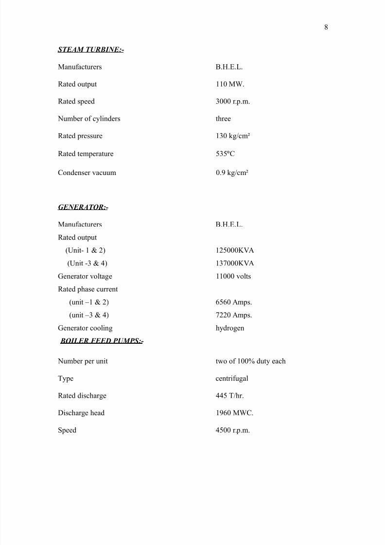
STEAM TURBINE:-
8anufacturers *.E.F.A.
;ated output ''0 8".
;ated speed =000 r.p.m.
Number of c#linders three
;ated pressure '=0 k!cmH
;ated temperature (=(°?
?ondenser vacuum 0. k!cmH
GENERATOR:-
8anufacturers *.E.F.A.
;ated output
/3nit- ' < ) ')(000I2
/3nit -= < & '=9000I2
Generator voltae ''000 volts
;ated phase current
/unit J' < ) 6(60 2mps.
/unit J= < & 9))0 2mps.
Generator coolin h#droen
BOILER FEED PUMPS:-
Number per unit two of '00B dut# each
T#pe centrifual
;ated dischare &&( T!hr.
Dischare head '60 8"?.
1peed &(00 r.p.m.
:
8/9/2019 Guru Nanak Dev Thermal Power
http://slidepdf.com/reader/full/guru-nanak-dev-thermal-power 9/120
CIRCULATING WATER PUMPS:-
Numbers for two units five of (0B dut# each
T#pe mi4ed flow
;ated dischare :600 T!hr.
Dischare head )& 8"?.
COOLING TOWERS:-
Numbers four
"ater cooled ':000 T!hr.
?oolin rane '0°?
Eeiht ')0!') metres
COAL PULVERISING MILLS:-
Numbers three per unit
T#pe drum-ball
;ated output )9 T!hr.
?oal bunkers '6 per unit
RATING OF 6.6 KV AUXILLIARY MOTORS:-
?oal mill 6=0 I"
apour fan =)0 I"
?.". an :00!9&6 I"

8/9/2019 Guru Nanak Dev Thermal Power
http://slidepdf.com/reader/full/guru-nanak-dev-thermal-power 10/120
?oal crusher ()0 I"
Primar# air fan =)0 I"
orced drauht fan =)0 I"
*oiler feed pump =(00 I"
>nduced drauht fan 00!'000 I"
?ondensate pump '9( I"
'0
8/9/2019 Guru Nanak Dev Thermal Power
http://slidepdf.com/reader/full/guru-nanak-dev-thermal-power 11/120
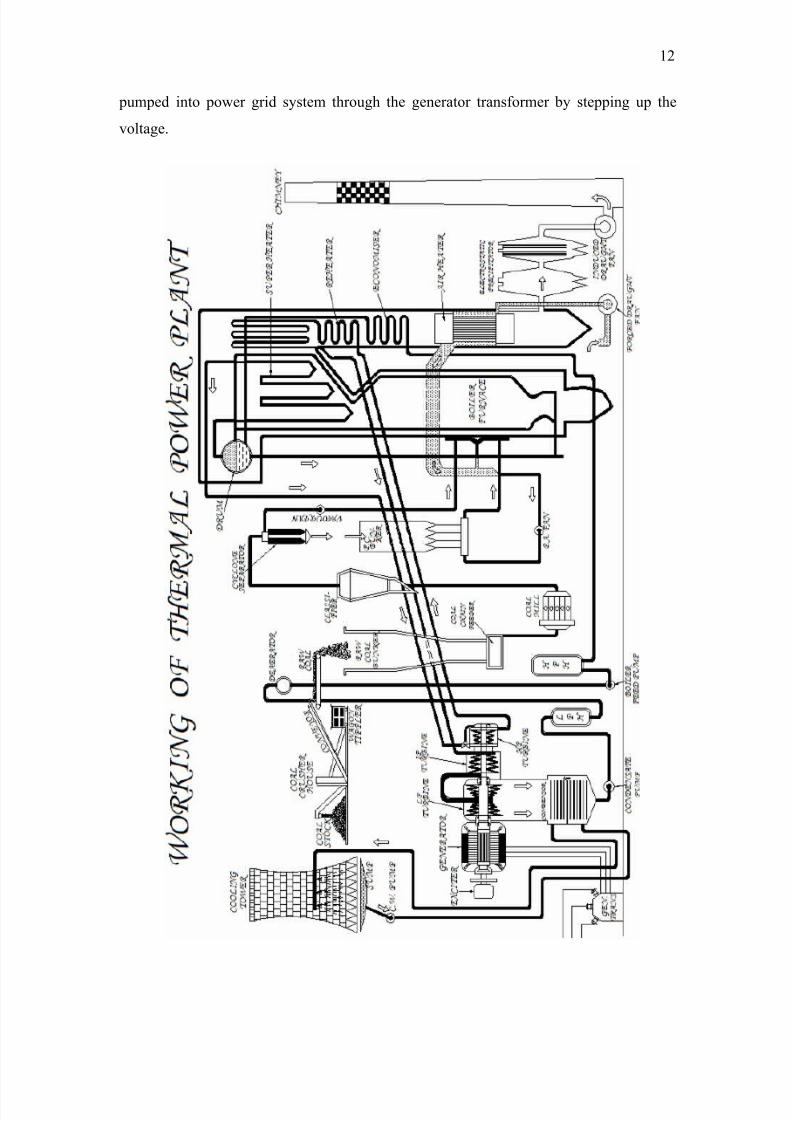
?oal received from collieries in the rail waon is mechanicall# unloaded b#
"aon Tippler and carried b# belt ?onve#or 1#stem *oiler ;aw ?oal *unkers after
crushin in the coal crusher. The crushed coal when not required for ;aw ?oal *unker is
carried to the coal storae area throuh belt conve#or. The raw coal feeder reulates the
quantit# of coal from coal bunker to the coal mill$ where the coal is pulveri%ed to a fine
powder. The pulveri%ed coal is then sucked b# the vapour fan and finall# stored in
pulveri%ed coal bunkers. The pulveri%ed coal is then pushed to boiler furnace with the
help of hot air steam supplied b# primar# air fan. The coal bein in pulveri%ed state ets
burnt immediatel# in the boiler furnace$ which is comprised of water tube wall all around
throuh which water circulates. The water ets converted into steam b# heat released b#
the combustion of fuel in the furnace. The air required for the combustion if coal is
supplied b# forced drauht fan. This air is however heated b# the outoin flue ases in
the air heaters before enterin the furnace.
The products of combustion in the furnace are the flue ases and the ash. 2bout
)0B of the ash falls in the bottom ash hopper of the boiler and is periodicall# removed
mechanicall#. The remainin ash carried b# the flue ases$ is separated in the electrostatic
precipitators and further disposed off in the ash dampin area. The cleaner flue ases are
let off to atmosphere throuh the chimne# b# induced drauht fan.
The chemicall# treated water runnin throuh the water walls of boiler furnace
ets evaporated at hih temperature into steam b# absorption of furnace heat. The steam
is further heated in the super heater. The dr# steam at hih temperature is then led to the
turbine comprisin of three c#linders. The thermal ener# of this steam is utili%ed in
turbine for rotatin its shaft at hih speed. The steam dischared from hih pressure
/E.P. turbine is returned to boiler reheater for heatin it once aain before passin it into
the medium pressure /8.P. turbine. The steam is then let to the coupled to turbine shaft
is the rotor of the enerator$ which produces electricit#. The power from the enerator is
''
WORKING OF
THERMAL
PLANT
8/9/2019 Guru Nanak Dev Thermal Power
http://slidepdf.com/reader/full/guru-nanak-dev-thermal-power 12/120
pumped into power rid s#stem throuh the enerator transformer b# steppin up the
voltae.
')
8/9/2019 Guru Nanak Dev Thermal Power
http://slidepdf.com/reader/full/guru-nanak-dev-thermal-power 13/120
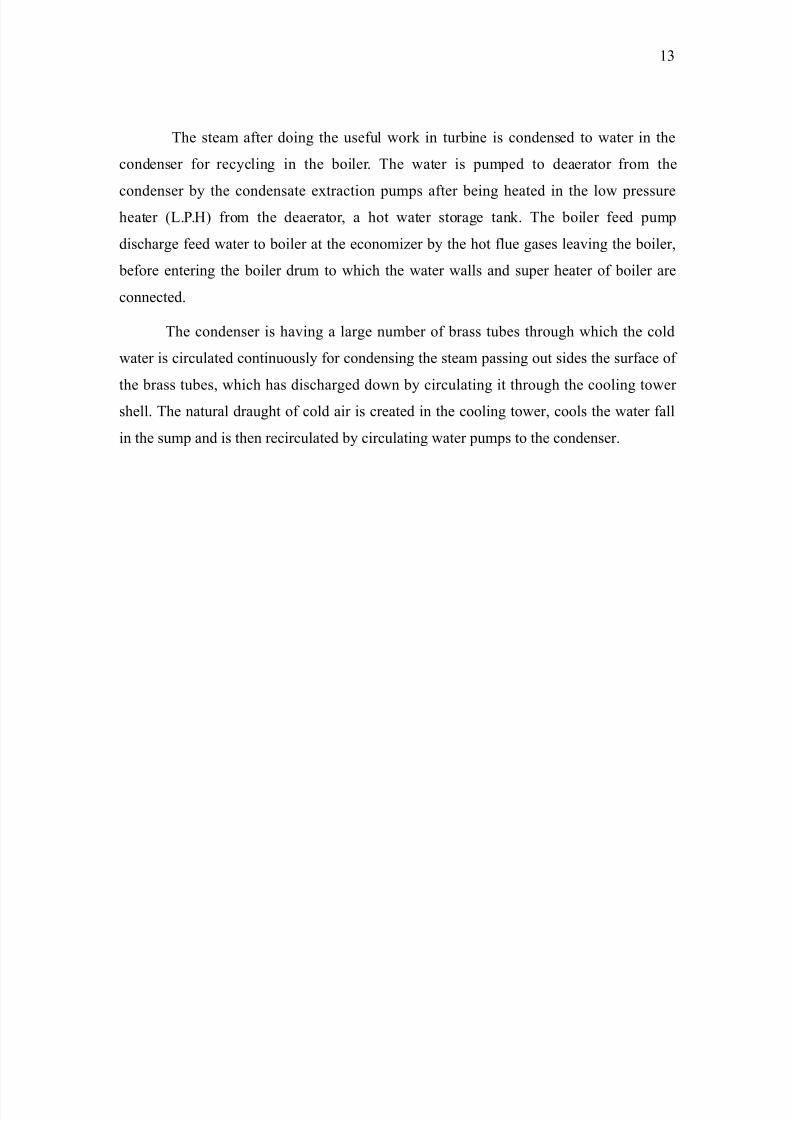
The steam after doin the useful work in turbine is condensed to water in the
condenser for rec#clin in the boiler. The water is pumped to deaerator from the
condenser b# the condensate e4traction pumps after bein heated in the low pressureheater /A.P.E from the deaerator$ a hot water storae tank. The boiler feed pump
dischare feed water to boiler at the economi%er b# the hot flue ases leavin the boiler$
before enterin the boiler drum to which the water walls and super heater of boiler are
connected.
The condenser is havin a lare number of brass tubes throuh which the cold
water is circulated continuousl# for condensin the steam passin out sides the surface of
the brass tubes$ which has dischared down b# circulatin it throuh the coolin tower shell. The natural drauht of cold air is created in the coolin tower$ cools the water fall
in the sump and is then recirculated b# circulatin water pumps to the condenser.
'=
8/9/2019 Guru Nanak Dev Thermal Power
http://slidepdf.com/reader/full/guru-nanak-dev-thermal-power 14/120
BOILER FEED PUMP:-
2s the heart is to human bod#$ so is the boiler feed pump to the steam power plant. >t is
used for rec#clin feed water into the boiler at a hih pressure for reconversion into
steam. Two nos. '00B dut#$ barrel desin$ hori%ontal$ centrifual multistae feed pumps
with h#draulic couplin are provided for each unit. This is the larest au4iliar# of the
power plant driven b# =(00 I" electric motor.
The capacit# of each boiler at GURU NANAK DEV THERMAL PLANT is
=9( tones!hr. The pump which supplies feed water to the boiler is named as boiler feed
pump. This is the larest au4iliar# in the unit with '00B capacit# which takes suction of
feed water from feed water tank and supplies to the boiler drum after preheatin the same
in EP-'$ EP-) and economi%er. The deliver# capacit# of each boiler feed pump is &&(
tones!hr. to meet better requirements correspondin to the various loads$ to control steam
temperature$ boiler make up water etc. The detailed particulars checkin of protections
and inter locks$ startin permission etc. are as below,-
Part!"#ar$ %& BFP a'( t$ )a' )%t%r:-
BOILER FEED PUMP: - The ''0 8" turboset is provided with two boiler feed
pumps$ each of '00B of total quantit#. >t is of barrel desin and is of hori%ontal
arranement$ driven b# an electric motor throuh a h#draulic couplin.
T#pe )00 IE>
No. of staes 6
Deliver# capacit# &&( t!hr.
eed water temperature '(:°?
1peed &(00 rpm
Pressure at suction :.=0 k!cmH
1tuffin bo4 mechanical seal
Aubrication of pump b# oil under pressure
'&
GENERAL
DESCRIPTION
8/9/2019 Guru Nanak Dev Thermal Power
http://slidepdf.com/reader/full/guru-nanak-dev-thermal-power 15/120
2nd motor bearin supplied b# h#draulic couplin
?onsumption of coolin water )=0 A!min.
WATER TREATMENT PLANT:-
The water before it can be used in the boiler has to be chemicall# treated$ since untreated
water results in scale formation in the boiler tubes especiall# at hih pressure and
temperatures. The water is demineralised b# >on F4chane Process. The water treatment
plant has production capacit# of ':00 Tonnes per da# for meetin the make-up water
requirement of the power station.
COAL MILL:-
?oal 8ill pulveri%es the raw coal into a fine powder before it is burnt in the boiler
furnace. The pulveri%in of coal is achieved with the impact of fallin steel balls$
weihin ().( tonnes$ contained in the mill drum rotatin at a slow speed of '9.( r.p.m.
The raw coal is dried$ before pulveri%in$ with inert hot flue ases tapped from the boiler.
Three coal mills each with a pulveri%in capacit# of )9 T!hr. are provided for one unit.
INDUCED DRAUG*T FAN:-
Two nos. a4ial flow >nduced Drauht ans are provided for each unit to e4haust ash laden
flue ases from boiler furnace throuh dust e4traction equipment and to chimne#. The fan
is driven b# an electric motor throuh a fle4ible couplin and is equipped with remote
controlled reulatin vanes to balance drauht conditions in the furnace. The fan is
desined to handle hot flue ases with a small percentae of abrasive particles in
suspension.
CONTROL ROOM:-
The control room is the operational nerve center of the power plant. The performance of
all the equipments of the plant is constantl# monitored here with the help of sophisticatedinstrumentation and controllers. 2n# adverse deviation in the parameters of various
s#stems is immediatel# indicated b# visual and audio warnin and suitable corrective
action is taken$ accordinl#. The control room is air conditioned to maintain the desired
temperature for proper functionin of the instruments.
'(
8/9/2019 Guru Nanak Dev Thermal Power
http://slidepdf.com/reader/full/guru-nanak-dev-thermal-power 16/120
SWITC* YARD:-
Flectricit# enerated at '' I b# the turbo-set is stepped-up b# unit transformers to
'=)!))0 I for further transmission throuh hih tension lines to 8aur$ 8uktsar$
8alout$ N..A.$ 1anrur and Audhiana. Transmission of power to rid is controlled
throuh 9 nos. ))0 I and '( nos. '=) I. 2ir *last ?ircuit *reakers alon with their
associated protective s#stems.
WAGON TIPPLER:-
The coal received from the collieries$ in more than '00 rail waons a da#$ is unloaded
mechanicall# b# two nos. waon tipplers out of which one serves as a standb#. Fach
loaded waon is emptied b# tipplin it in the underround coal hopper from where the
coal is carried b# conve#or to the crusher house. 2rranements have been provided for
weihin each rail waon before and after tipplin. Fach tippler is capable of unloadin
6-: rail waons of (( tonnes capacit# in an hour.
CRUS*ER *OUSE:-
?oal unloaded b# the waon tippler is carried to crusher house throuh conve#ors for
crushin. Two nos. hammer t#pe coal crushers are provided$ which can crush coal to a
si%e of '0 mm. The crushed coal is then supplied to *oiler ;aw ?oal *unkers. The
surplus coal is carried to coal storae area b# series of conve#ors. ?rushin of coal is an
essential requirement for its optimum pulveri%in and safe storae.
COOLING TOWERS:-
?oolin Towers of the power plant are the land mark of the *athinda ?it# even for a far
distance of :-'0 kilometers. @ne coolin tower is provided for each unit for coolin
':000 tones of water per hour b# '0°?. coolin towers are massive erro-concrete
structure havin h#perbolic profile creatin natural drauht of air responsible for
achievin the coolin effect. ?oolin tower is as hih as &0 store# buildin.
'6
8/9/2019 Guru Nanak Dev Thermal Power
http://slidepdf.com/reader/full/guru-nanak-dev-thermal-power 17/120
BOILER:-
>t is a sinle drum$ balanced drauht$ natural circulation$ reheat t#pe$ vertical combustion
chamber consists of seamless steel tubes on all its sides throuh which water circulates
and is converted into steam with the combustion of fuel. The temperature inside the
furnace where the fuel is burnt is of the order of '(00 °?. The entire boiler structure is of
&)meter heiht.
BOILER C*IMNEY:-
The flue from the boiler$ after removal of ash in the precipitators$ are let off to
atmosphere throuh boiler chimne#$ a tall ferro-concrete structure standin as hih as the
historic Kutab 8inar. our chimne#s$ one for each unit$ are installed. The chimne# is
lined with fire bricks for protection of ferro-concrete aainst hot flue ases. 2 protective
coatin of acid resistant paint is applied outside on its top '0 meters.
CIRCULATING WATER PUMP:-
Two nos. of circulatin water pumps provided for each unit$ circulate water at the rate of
'9)00 T!hr. in a closed c#cle comprisin of Turbine ?ondenser and ?oolin Tower. 2n
additional ?irculatin "ater Pump provided serves b# for two units. The water
requirement for bearin coolin of all the plant au4iliaries is also catered b# these pumps.
'9
8/9/2019 Guru Nanak Dev Thermal Power
http://slidepdf.com/reader/full/guru-nanak-dev-thermal-power 18/120
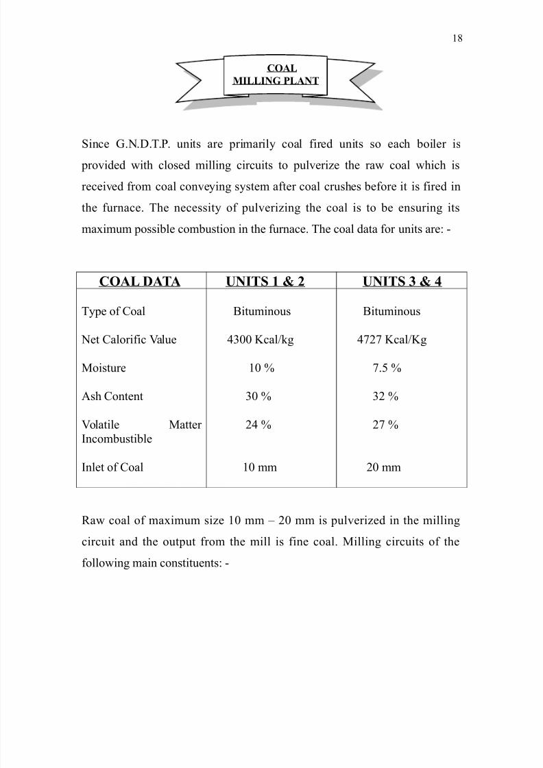
1ince G.N.D.T.P. units are primaril# coal fired units so each boiler is
provided with closed millin circuits to pulveri%e the raw coal which is
received from coal conve#in s#stem after coal crushes before it is fired in
the furnace. The necessit# of pulveri%in the coal is to be ensurin its
ma4imum possible combustion in the furnace. The coal data for units are, -
COAL DATA UNITS 1 & 2 UNITS 3 & 4
T#pe of ?oal
Net ?alorific alue
8oisture
2sh ?ontent
olatile 8atter
>ncombustible
>nlet of ?oal
*ituminous
&=00 Ical!k
'0 B
=0 B
)& B
'0 mm
*ituminous
&9)9 Ical!I
9.( B
=) B
)9 B
)0 mm
;aw coal of ma4imum si%e '0 mm J )0 mm is pulveri%ed in the millin
circuit and the output from the mill is fine coal. 8illin circuits of the
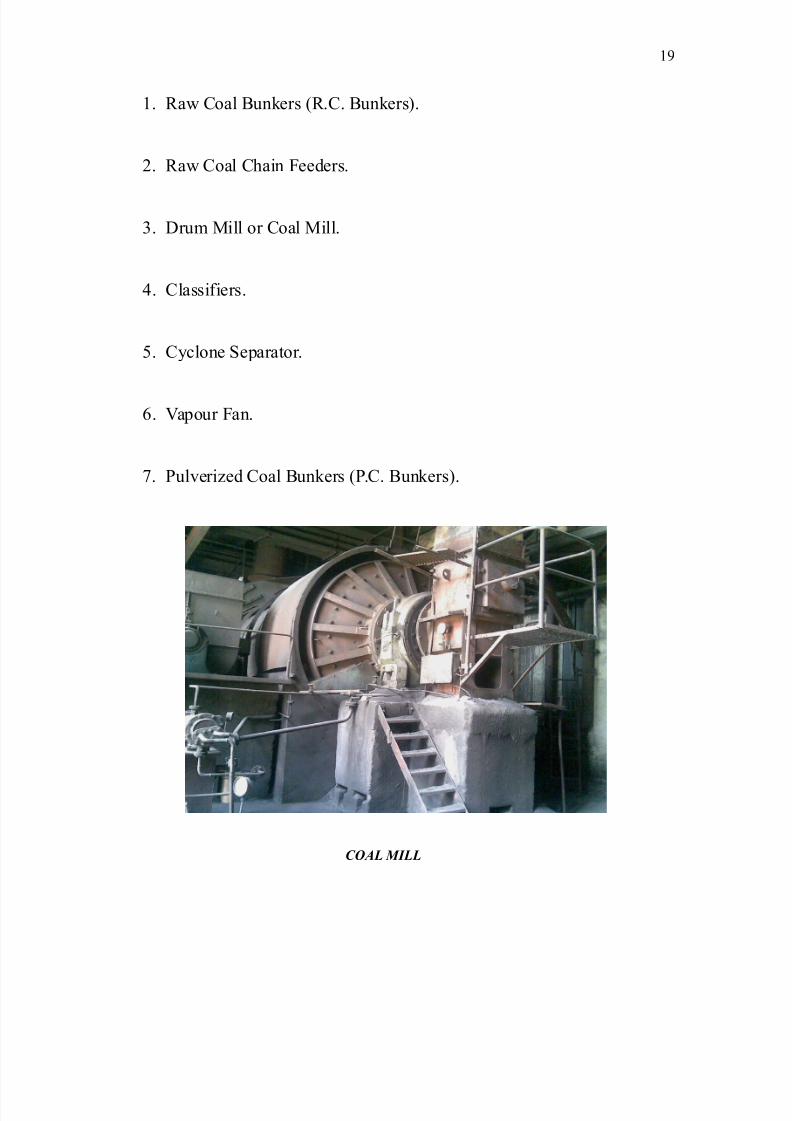
followin main constituents, -
':
COAL
MILLING PLANT
8/9/2019 Guru Nanak Dev Thermal Power
http://slidepdf.com/reader/full/guru-nanak-dev-thermal-power 19/120
'. ;aw ?oal *unkers /;.?. *unkers.
). ;aw ?oal ?hain eeders.
=. Drum 8ill or ?oal 8ill.
&. ?lassifiers.
(. ?#clone 1eparator.
6. apour an.
9. Pulveri%ed ?oal *unkers /P.?. *unkers.
COAL MILL
'
8/9/2019 Guru Nanak Dev Thermal Power
http://slidepdf.com/reader/full/guru-nanak-dev-thermal-power 20/120
RAW COAL BUNKER:-
Fach of three raw coal bunkers is fabricated from the sheet metal and is well stiffened all
around. The storae capacit# of each raw coal bunker is about (00 tones. There are four
outlet ates with each bunker. The ates are electricall# operated from site. >n case of failure of the electric motors the ate can be hand operated from site. 2t a time onl# one
ate openin is suffices but should be chaned so that there is no pillin within the
bunker.
RAW COAL C*AIN FEEDER:-
The raw coal chain feeder transports coal from raw coal bunker to the inlet chute leadin
to the pulveri%ed!coal mills. There is a double link chain of hih tensile strenth steel$
which moves on wheels and sweeps the raw coal fallin over the top of the raw coal
chute of the mill. The heiht of the coal bed in the chain feeder can be ad5usted manuall#
b# means of lever operated damper. The ma4imum and minimum heihts of the coal bed
are )00mm and ')0mm respectivel#. The sinalin equipment indicates the absence of
coal flow in the feeder$ which is annunciated in the unit control board /3.?.*.. The main
shaft on the drivin end is connected to the drivin unit$ consistin of variator$ a ear bo4
and a motor all mounted as a sinle unit. The chain wheel on the drivin end shaft is
provided with a shear pin$ which will shear off and disconnect the drivin mechanism if
there is an# overload on the feeder. The speed of the chain feeder is reulated
automaticall#!remotel# b# actuatin the control spindle of the variator throuh a
servomotor. 2 pump for circulatin the oil in the ear bo4 of variator is an interal part of
variator driven b# a separator motor. 1ome of the technical data about the raw coal chain
feeder is iven here,-
'. @utput of the chain feeder '0-&( tonnes!hr.
). 1peed variations 0.0(0=-0.'('m!sec.=. 8ain motor 9.(k"$ &'($ (0E%.
&. @il pump motor 0.0(k"$ ))0
(. @peratin motor of each ate =EP$ &'( and (0E%.
)0
8/9/2019 Guru Nanak Dev Thermal Power
http://slidepdf.com/reader/full/guru-nanak-dev-thermal-power 21/120
DRUM MILL:-
Fach mill consists of sinle compartment drum$ bearins drivin motor$ coal inlet
and dischare pipin$ ball chane and lubricatin equipment for mill bearins. 8ill drum
is fabricated from thick steel plates and is supported on to the anti-friction bearins. Themill is driven b# an electric motor of capacit# 6=0k"$ 0 rpm$ 6.6k throuh a
reduction ear$ which reduces the speed to '9.( rpm. The ball chare for the mill consists
of the three different si%es of fored steel balls detailed as below. The capacit# of each
mill is )9 T!hr. in case of unit ' < ) and ): T!hr.
'. &0mm diameter ))(00 k
). (0mm diameter )0000k
=. 60mm diameter '0000k
4. To!" B!"" C#!$% '2'(()%
Durin operation onl# 60mm diameter balls are added is appro4. (00 k per week
and the uidin factor is the amperae of the coal mill$ normall# it should be 66-ampere
appro4. at full load and when it falls below the above value ball charin of the mill is
carried out. Aubricatin s#stem consists of the oil tank$ ear pump$ oil cooler and base
frame to mount all these equipments. Gear pump is driven b# an electric motor of ratin '
E.P.$ &'( $ '&&0 rpm. 1uction side of the ear pump is connected to the tube oil tank and
the deliver# side is connected to inlet of the oil cooler and after coolin oil oes to the
bearins. The oil from the bearins is cooled to the required temperature in the cooler b#
the means of plant bearin cooler water.
CLASSIFIER:-
The classifier is fabricated from the steel plates. >t is an equipment that separates fine
pulveri%ed coal from the coarser pieces. The pulveri%ed coal alon with the carr#in as
well as dr#in medium /flue as strikes the impact plate in the classifier and the coarser
pieces et separated due to the chane in the direction of flow and o back to mill. The
stream then passes to the outlet branch of the classifier throuh an ad5ustable telescopic
tube. 2t the outlet ad5ustable vanes are provided to chane the si%e of coal when required.
)'
8/9/2019 Guru Nanak Dev Thermal Power
http://slidepdf.com/reader/full/guru-nanak-dev-thermal-power 22/120
CYCLONE SEPARATOR:-
The centrifual t#pe c#clone separator consists of two c#clones made up of welded
sheets. >t is equipment in the millin plant$ which serves for separatin the pulveri%ed
coal from the vapours i.e. carr#in medium. The pulveri%ed coal ets stored in the pulveri%ed coal bunkers and vapours o to suction of vapour fan. 2t the bottom of the
c#clone separator a rotar# valve /Turnikete is provided to transport coal from c#clone
separator to P.?. bunker on the worm conve#or as the case ma# be.
VAPOUR FAN:-
Pulveri%ed coal bunker is welded from thick steel sheets and has a capacit# of & hours
coal consumption at ma4imum continuous ratin of the boiler. The whole bunker is
insulated e4ternall#. The carbon-dio4ide blanketin s#stem has been provided in the P.?.
bunker to prevent fire ha%ards inside the bunker. The while storae bunker is divide into
four parts namel# 2$ * ? < D. urther four coal feeders are taken out from each bunker
leadin to each corner of the furnace.
CRUS*ING OF COAL:-
"hen coal reaches the plant$ normal si%e of coal is about (00mm. 2fter unloadin the
coal from the rake is fed to primar# crusher$ which reduces the si%e to ')0mm. Then coal
is fed to secondar# crusher which reduces the si%e to )(mm and this coal oes to bunker
with the help of conve#or belt from where coal finall# oes to coal mill where coal is
transferred in form of pulveri%ed coal. The coal is heated with the help of hot primar# air.
"e maintain the temperature of about 90°? in coal mill. This temperature is maintained
with the help of cold air and a hot air damper.
USE OF OIL:-
*efore the coal reaches the furnace$ we preheat the furnace in order to remove the
moisture and raise the temperature of furnace$ so that coal can catch fire easil# without
an# dela#. This preheatin of furnace is done with the help of oil. "ith burnin of oil$ we
))
8/9/2019 Guru Nanak Dev Thermal Power
http://slidepdf.com/reader/full/guru-nanak-dev-thermal-power 23/120
maintain the temperature of furnace at =(0°?. we cut the oil suppl# after =(0°? because
oil is ver# costl#. 1ource of oil for G.N.D.T.P.$ *athinda is 8athura @il ;efiner#. @ther
use of oil is in bearin s#stem for coolin. There are lare number of bearins for plant.
or e4ample bearin s#stem of turbine. These bearins et heated upto hih temperature$
which is danerous. 1o we cool the bearin b# circulatin water in bearin.
COAL FEEDING AND COAL MILL:-
rom the coal handlin plant$ coal comes in two belts namel# (2 and (* and then b#
belts 62 and 6* coal comes in bunkers. *unker capacit# is =00 tonnes. Number of outlets
of bunker is three. irst ate is opened for one hour and second and then third. >f open the
one ate for lon time$ then coal will stop oin to mill. That is wh# we open the ate
turn b# turn.
RAW COAL C*AIN FEEDER:-
;aw coal chain feeder is 5ust below raw coal bunker. >t is a slidin chain which feed the
coal to mill. "e can chane the quantit# of coal which is fed to mill in two wa#s.
*# chanin the speed of chain
*# chanin the depth of coal in chain
1peed of chain can be chaned b# addin a ear s#stem to motor. "e connect the
ear s#stem with motor with a pin called shear pin. The prevent the overloadin of motor
because when the coal quantit# of coal on chain is reater than its capacit# then the pin
will break and prevent the pin from overloadin. 1peed of ;aw ?oal chain is )L to 6L!sec.
COAL MILL:-
These are mainl# of two t#pes,-
i *all 8ills
ii *owl 8ills
)=
8/9/2019 Guru Nanak Dev Thermal Power
http://slidepdf.com/reader/full/guru-nanak-dev-thermal-power 24/120
Ba## M##$: - >n *all 8ills there are steel balls which are revolvin in hori%ontal
c#lindrical drum. These balls are free from an# shaft and balls are touchin with each
other and with internal bod# of drum. These t#pes of mills are at *athinda Thermal Plant.
@n the other hand$ bowl mills part of the mill contain drive s#stem i.e. it contains 6.6 k
electric motor and ear s#stem which translates the revolution about hori%ontal a4is to
revolve about vertical a4is. The revolvin vertical a4is contains a bowl about the drivin
s#stem. This bowl is fi4ed with drivin and revolvin with shaft. There are also three
rollers which are suspended at some inclination$ so that there is a ap of few mm between
roller surface. These rollers are free to rotate about the a4is.
Bo*" M+""- The coal is rinded and then fed into the mill at the center or near of
revolvin bowl. >t passes between the rindin rin in revolvin bowl and rolls as
centrifual force causes the material to travel towards the out perimeter of bowl. The
sprins$ which load the rolls$ impart the necessar# force for rindin. The partiall#
pulveri%ed coal continue oin up and down and over the ede of bowl.
)&
8/9/2019 Guru Nanak Dev Thermal Power
http://slidepdf.com/reader/full/guru-nanak-dev-thermal-power 25/120
The G.N.D.T.P. units are primaril# coal-fired units and the coal consumption at
ma4imum continuous ratin /8.?.;. per unit is about (: T!Er. the coal used at
G.N.D.T.P. is of bituminous and sub-bituminous t#pe and this is received from some
collieries of 8.P. and *ihar. The desined composition of coal is as below,-
T#pe *ituminous ?oal
Net calorific value &=00 kcal!k
8oisture content in coal '0B
2sh content =0B
olatile matter in combustibles )&B
Grind abilit# inde4 (0 Eard Groove
The coal handlin plant at G.N.D.T.P. has been supplied and erected b# 8!s Flecon
Fnineerin ?ompan# Aimited$ allabh id#a Naar$ Guarat. ?oal is transported from
the coal mines to the plant site b# ;ailwa#s. Generall#$ the raw coal comes b# railwa#
waons of either eiht wheels weihin about 9( to :0 tones each or four wheels
weihin about =( to &0 tones each. The loaded waon rake is brouht b# railwa#s main
line loco and left on one of the loaded waon tracks in the power station marshallin
#ard. The main line loco escapes throuh the enine track. The station marshallin #ard is
provided with : tracks. The arranement of the tracks in the marshallin #ard is as
follows,-
DESTINATION NO. OF TRACKS
Aoaded waons receivin tracks our
Fmpt# waon standin tracks Three
Fnine escape tracks @ne
)(
COAL HANDLING PLANT
/CHP0
8/9/2019 Guru Nanak Dev Thermal Power
http://slidepdf.com/reader/full/guru-nanak-dev-thermal-power 26/120
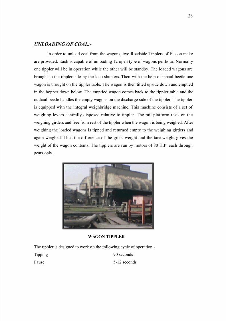
UNLOADING OF COAL:-
>n order to unload coal from the waons$ two ;oadside Tipplers of Flecon make
are provided. Fach is capable of unloadin ') open t#pe of waons per hour. Normall#
one tippler will be in operation while the other will be standb#. The loaded waons are
brouht to the tippler side b# the loco shunters. Then with the help of inhaul beetle one
waon is brouht on the tippler table. The waon is then tilted upside down and emptied
in the hopper down below. The emptied waon comes back to the tippler table and the
outhaul beetle handles the empt# waons on the dischare side of the tippler. The tippler
is equipped with the interal weihbride machine. This machine consists of a set of
weihin levers centrall# disposed relative to tippler. The rail platform rests on the
weihin irders and free from rest of the tippler when the waon is bein weihed. 2fter
weihin the loaded waons is tipped and returned empt# to the weihin irders and
aain weihed. Thus the difference of the ross weiht and the tare weiht ives the
weiht of the waon contents. The tipplers are run b# motors of :0 E.P. each throuh
ears onl#.
WAGON TIPPLER
The tippler is desined to work on the followin c#cle of operation,-
Tippin 0 seconds
Pause (-') seconds
)6
8/9/2019 Guru Nanak Dev Thermal Power
http://slidepdf.com/reader/full/guru-nanak-dev-thermal-power 27/120
;eturn 0 second1
"eihin =0 seconds
Total )'(-))) seconds
2llowin :( seconds for waon chanin it will be seen that ') eiht-wheel waons or
)& four-wheel waons per hours can be tipped. Eowever since the coal carr#in capacit#
is (00 tones per hour load of ') waons comes to : to per hour.
DUST TRAPPING SYSTEM:-
The tippler is also provided with the dust trappin s#stems b# which the dust nuisance
will be minimi%ed. 2s the tippler rotates$ a normall# closed hopper valve opens
automaticall# and the dischared material passes throuh it into the hopper with its dust-
settin chamber$ there is an air valve of lare area$ which opens$ simultaneousl# with the
hopper valve. The ob5ect of this air valve is to blow back throuh the hopper valve into
the tippin chamber$ which must occur if$ the settlin chamber were closed$ it bein
remembered that a lare waon contains some )&0 cubic feet of material and that this
volume of dust air would be forced back at each tip if the hopper chamber were a Mclosed
bottleL. The air valve and the hopper valve are shut immediatel# on reversal of the tippler
and are kept shut at all times e4cept durin the actual dischare. The hopper valve is
operated b# a motor of '0 E.P.$ &'( olts and the air valve is operated b# electro-
h#draulic thruster. >nlet valve consists of lare number of plates slidin under the waon
tippler ratin. ?oal in the waon tippler hopper forms the heap and as such obstructs the
movement of slidin valve and damain the plates. The inlet and outlet valves have
therefore been b#passed.
The unloaded material falls into the waon tippler hopper /common to both
tipplers havin a capacit# of )'0 tones. The hopper has been provided with a ratin of
=00mm =00mm si%e at the top so as to lare si%e boulders ettin into the coal stream.
There is also a provision of unloadin the waons manuall# into the 82N32AA
3NA@2DFD E@PPF; of ''0 tones capacit#. 8anuall# unloadin will be restored to
while unloadin coal from sick waons or closed waons.
)9
8/9/2019 Guru Nanak Dev Thermal Power
http://slidepdf.com/reader/full/guru-nanak-dev-thermal-power 28/120
MAGNETIC PULLEYS:-
@n belt conve#or no. &2 and &*$ there have been provided hih intensit#
electromanetic pulle#s for separatin out tramp iron particles!pieces from the main
stream of coal conve#in. D.?. suppl# for the manet is taken on &'( volt$ = phase$ (0
c#cles 2.?. suppl# s#stem.
>n addition to above hih intensit# suspension t#pe electromanets have also been
provided on belt conve#ors &2 and &* for separatin out tramp iron pieces!particles.
RECLAIMING:-
>f the receipt of coal on an# da# more than the requirement of the boilers$ the
balanced material will be stocked via conve#or 92and 9* and throuh telescopic chute
fitted at the end of the conve#or. 2t the end of the chute one tele level switch is provided$
which automaticall# lifts the telescopic chute to a predetermined heiht ever# time. The
tele level switch is actuated b# the coal pile. "hen the telescopic chute reaches ma4imum
heiht durin operation$ which will be cut off b# limit$ switch and stop the conve#in
s#stem. "hen the pile under the telescopic chute is cleared$ the telescopic chute can be
independentl# lower manuall# b# push buttons.
There are five bulldo%ers to spread and compact the coal pile. *ulldo%ers of *harat Farth
8overs Aimited 8ake are fitted with )(0 E.P. diesel enines. Fach bulldo%er is able to
spread the crushed coal at the rate of )(0 tones!hr. over a load distance of 60m the coal
can be stacked to a heiht of 6m the stockpile stores coal for about &( da#s for four units
with an annual load factor of 0.66.
"henever coal is to be reclaimed the bulldo%ers are emplo#ed to push the coal in
the reclaim hopper havin a capacit# of ''0 tones. The coal from the reclaim hopper is
fed either 2 or * belt conve#or throuh vibrator# feeders :2 and :*.
CRUSHER HOUSE-
):
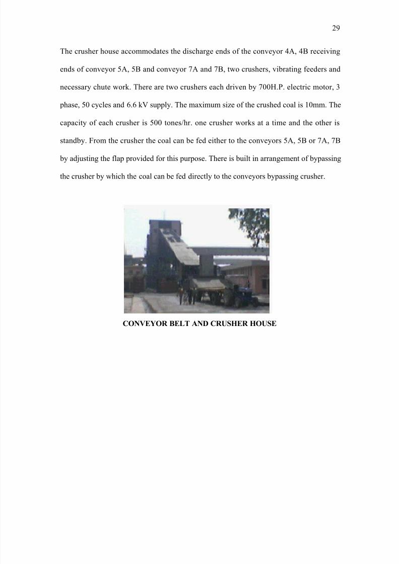
8/9/2019 Guru Nanak Dev Thermal Power
http://slidepdf.com/reader/full/guru-nanak-dev-thermal-power 29/120
The crusher house accommodates the dischare ends of the conve#or &2$ &* receivin
ends of conve#or (2$ (* and conve#or 92 and 9*$ two crushers$ vibratin feeders and
necessar# chute work. There are two crushers each driven b# 900E.P. electric motor$ =
phase$ (0 c#cles and 6.6 k suppl#. The ma4imum si%e of the crushed coal is '0mm. The
capacit# of each crusher is (00 tones!hr. one crusher works at a time and the other is
standb#. rom the crusher the coal can be fed either to the conve#ors (2$ (* or 92$ 9*
b# ad5ustin the flap provided for this purpose. There is built in arranement of b#passin
the crusher b# which the coal can be fed directl# to the conve#ors b#passin crusher.
CONVEYOR BELT AND CRUSHER HOUSE
)

8/9/2019 Guru Nanak Dev Thermal Power
http://slidepdf.com/reader/full/guru-nanak-dev-thermal-power 30/120
=0
8/9/2019 Guru Nanak Dev Thermal Power
http://slidepdf.com/reader/full/guru-nanak-dev-thermal-power 31/120
SWITCH GEAR
INTRODUCTION
The apparatus includin its associated au4iliaries emplo#ed for switchin$ controllin and
protectin the electrical circuits and equipments is known as switchear.
2 tumbler switch$ which is an ordinar# fuse$ is the simplest form of switchear and is
enerall# used to control and protect the domestic and commercial appliances and
equipments. or hih ratin circuits$ a hih rupturin capacit# /E.;.?. fuse in
conduction with switch ma# serve the purpose. Eowever$ such switchear cannot be
applied on power s#stem operatin at hih voltaes$ i.e. more than '' I because of the
followin reasons, -
'. "hen fuse blows$ it takes sometime to replace it and consequentl# there is
interruption of power suppl#.
). @n hih voltae s#stem$ a fuse cannot successfull# interrupt lare fault currents.
=. "hen fault occurs$ fault takes sometime to blow. Durin this time the costl#
equipments e.. enerators$ transformers etc. ma# be damaed.
Therefore in order to protect lines$ enerators$ transformers and other electrical
equipments from damae$ an automatic protective device or switchear are required.
2utomatic protective switchear mainl# consists of the rela#s and circuit breakers. 2
circuit breaker is switchear$ which can be open or close the circuit after an operation.
Therefore$ a circuit breaker is rather preferred even in the instance when a fuse is
adequate.
S+t!, : -
>t makes and breaks the circuit under full load or no load condition but cannot be
operated under fault conditions. >t is enerall# operated manuall#.
I$%#at%r: -
>t is onl# operated under no load conditions. >ts main purpose is to isolate a portion of
the circuit from the other. >solators are enerall# place on the both sides of a circuit
='
8/9/2019 Guru Nanak Dev Thermal Power
http://slidepdf.com/reader/full/guru-nanak-dev-thermal-power 32/120
breaker from the other in order to make repairs and maintenance on the circuit breaker
without an# daner. There are two t#pes of isolators, -
TYPES OF ISOLATER:-
• 1inle pole >solator
• Double pole >solator
FUSES:-
2 fuse is short piece of metal$ insert in series with the circuit$ which melt e4cessive
current flows throuh it and thus breaks the circuit. The material used for the fuse
element should possess the followin properties, -
• Aow meltin point.
• Eih conductivit#.
• ree from o4idation.
The common materials used for the fuse element are copper$ tin-lead allo# /tin 6=B and
lead =9B$ silver$ aluminum etc. 2 fuse is connected in series with the circuit to be
protected and carries the load current without overheatin under normal conditions.
Eowever when abnormal condition occurs$ an e4cessive current flows throuh it. This
raises the temperature$ which melt the fuse element and open the circuit. This protects the
machine or apparatus from the damae$ which can be used b# e4cessive currents.
CIRCUIT BREAKERS
?ircuit breaker is on!off switch operatin in an electric circuit in normal as well as
abnormal operatin conditions. "hile makin or breakin contact there is a transition
stae of arcin between contacts which is overned b# electric dischare between the
contacts at instant of separation$ thus current continuous in the circuit till dischare
appears.
The stud# of this phenomenon is ver# important for desin and operational
characteristics of ?.*.
=)
8/9/2019 Guru Nanak Dev Thermal Power
http://slidepdf.com/reader/full/guru-nanak-dev-thermal-power 33/120
8/9/2019 Guru Nanak Dev Thermal Power
http://slidepdf.com/reader/full/guru-nanak-dev-thermal-power 34/120
of the circuit breaker is eneri%ed$ which pulls apart the movin contacts from the fi4ed
contacts as shown in fi thus opens the circuit.
"hen the movin contacts are separated from the fi4ed contacts$ an arc is struck
between them. The production of arc not onl# dela#s the current interruption process butalso enerates enormous heat which ma# cause damae to the equipments of the power
s#stem or the breaker itself. Therefore ever# effort is made to e4tinuish the arc produced
in the circuit breaker as quickl# as possible.
Cr!"t Bra0r Rat'$: -
2 circuit breaker is required to be operated under all conditions. Eowever this ma5or
dut# of the circuit breaker is to operate the circuit under short circuit condition. 3nder
short circuit conditions$ a circuit breaker is required to perform three ma5or duties, -
• >t must be capable of operatin circuit on the occurrence of the fault.
• >t must be capable of closin the circuit on fault.
• >t must be capable of carr#in a fault current safel# for a short time$ while another
circuit breaker /in series is clearin the fault.
2ccordin to the duties to be performed b# a circuit breaker$ there are three t#pes of
ratins, -
Bra0' Ca/a!t1: -
The r.m.s. value of current that a circuit breaker is capable of breakin at a recover#
voltae under specified conditions /i.e. recover# voltae and rate of recover# voltae is
known as breakin capacit# of a circuit breaker. *reakin ?apacit# in 82O √= × rated
voltae × rated breakin current × '0-6.
Ma0' Ca/a!t1: -
The peak or ma4imum value of the current /includin d.c. component durin the first
c#cle of the current wave after the circuit is closed b# the breaker /under dead short
=&
8/9/2019 Guru Nanak Dev Thermal Power
http://slidepdf.com/reader/full/guru-nanak-dev-thermal-power 35/120
circuit is called makin capacit#.8akin ?apacit#O √=× '.: × 1#mmetrical breakin
capacit#.
S,%rt T) Ca/a!t1: -
The period for which the circuit breaker is able to carr# the fault current while remaininclosed is called short time capacit# of the circuit breaker.
N%r)a# C"rr't Rat': -
The r.m.s. value of the current which a circuit breaker is capable of carr#in continuousl#
at its rated frequenc# under specified conditions without overheatin the arc or contacts is
called normal current ratin.
O# Cr!"t Bra0r: -
>n this circuit breaker+ the current carr#in contacts are immersed in transformer oil.
"hen the contacts are separated$ arc is struck between them. The heat of the arc
dissociates the oil and ases viz. E#droen etc are evolved. The h#droen as bubble
surrounds the arc and cool it downs which help in de-ioni%ation of the medium between
the contacts and e4tinuishes the arc. 8oreover$ ases setup turbulence in the oil and
force it into the arc space when the current is %ero which further helps in e4tinuishin
the arc.
A(2a'ta$: -
• >t absorbs the ener# of the arc b# decomposin the oil into ases.
• The ases evolved provide ood coolin effect.
• The surroundin oil enclose the pro4imit# to the arc provides coolin effect.
• >t has abilit# to flow in the arc space after the current is %ero.
• >t acts as insulator between the live contacts and earthed tank.
=(
8/9/2019 Guru Nanak Dev Thermal Power
http://slidepdf.com/reader/full/guru-nanak-dev-thermal-power 36/120
D$
a(2a'ta$:-
• >t is easil# inflammable.
• >t ma# form an e4plosive mi4ture with air.
• >t requires more maintenance.
M')") O# Cr!"t Bra0r: -
>n bulk oil circuit breaker$ transformer oil is not onl# used e4tinuish the arc but also
serves as insulation between the live and earthed parts. 2 heav# quantit# of oil$
dependin upon s#stem voltae$ is used in the bulk oil circuit breakers /about (000 liters
in ))0I s#stem. This not onl# increases the e4penses but also increases the fire risk.
Therefore minimum oil circuit breakers are desined in which onl# '0 B of the oil is
used to e4tinuish the arc. The container of minimum oil circuit breakers is supported on
porcelain insulators. To provide the required insulation between the live and earthed
parts. Thus the minimum oil circuit breakers also require less space for installation.
=6
8/9/2019 Guru Nanak Dev Thermal Power
http://slidepdf.com/reader/full/guru-nanak-dev-thermal-power 37/120
MOCB3$ have followin merits and demerits, -
Mrt$: -
=9
8/9/2019 Guru Nanak Dev Thermal Power
http://slidepdf.com/reader/full/guru-nanak-dev-thermal-power 38/120
a. >t requires lesser quantit# of oil i.e. onl# for arc e4tinction.
b. >t requires smaller space for installation.
c. ;isk of fire is considerabl# reduced.
d. Aesser maintenance.
D-Mrt$: -
a. Due to smaller quantit# of oil the deree of carboni%ation is increased
therefore oil needs replacement after each operation.
b. Proper desin is required to remove the ases from the contacts space
in time
BRIEF DESCRIPTION OF . KV41'V
SWITC*GEAR
SUPPLIED TO G.N.D.T.P. BAT*INDA
>n 6.6!0.&'( I switchear we have two unit transformer and one station T!f that after
steppin down the voltae$ fed it to two 6.6 I unit buses and to station bus. arious
feeders are connected to 6.6 I buses and in order to avoid complete shutdown$ suppl#
is maintained b# drawin suppl# from station bus$ to =* < &* bus. 1uppl# from =2 bus
is stepped down to &'( b# '000 I2 1"G; T! J ' < fed to &'( bus. 1ame in &*
bus. >n case of trippin standb# bus used. arious feeders are connected to these
buses."e enerate electricit# at '' I < step-down to 9 I b# 32T. ;atin of 32T T!
is '( 82 < station T!f is ))( 82$ ''!9 I.
CIRCUIT BREAKER USED IN INDOOR SWITC*GEAR: -
8ainl# two t#pes of ?*Cs are used in switchear accordin to the requirement, -
'. 6.6I 8@?*Cs
=:
8/9/2019 Guru Nanak Dev Thermal Power
http://slidepdf.com/reader/full/guru-nanak-dev-thermal-power 39/120
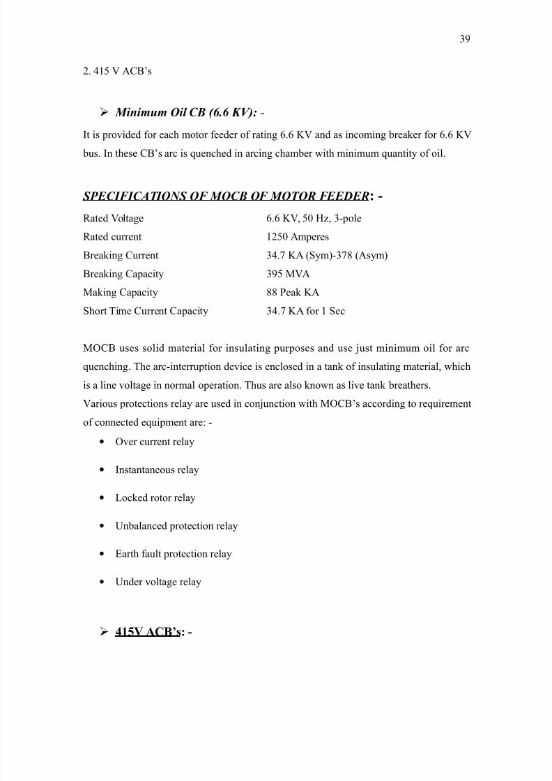
). &'( 2?*Cs
M')") O# CB 46.6 KV5: -
>t is provided for each motor feeder of ratin 6.6 I and as incomin breaker for 6.6 I
bus. >n these ?*Cs arc is quenched in arcin chamber with minimum quantit# of oil.
SPECIFICATIONS OF MOCB OF MOTOR FEEDER-
;ated oltae 6.6 I$ (0 E%$ =-pole
;ated current ')(0 2mperes
*reakin ?urrent =&.9 I2 /1#m-=9: /2s#m
*reakin ?apacit# =( 82
8akin ?apacit# :: Peak I2
1hort Time ?urrent ?apacit# =&.9 I2 for ' 1ec
8@?* uses solid material for insulatin purposes and use 5ust minimum oil for arc
quenchin. The arc-interruption device is enclosed in a tank of insulatin material$ which
is a line voltae in normal operation. Thus are also known as live tank breathers.
arious protections rela# are used in con5unction with 8@?*Cs accordin to requirement
of connected equipment are, -
• @ver current rela#
• >nstantaneous rela#
• Aocked rotor rela#
• 3nbalanced protection rela#
• Farth fault protection rela#
• 3nder voltae rela#
41'V ACB-
=
8/9/2019 Guru Nanak Dev Thermal Power
http://slidepdf.com/reader/full/guru-nanak-dev-thermal-power 40/120
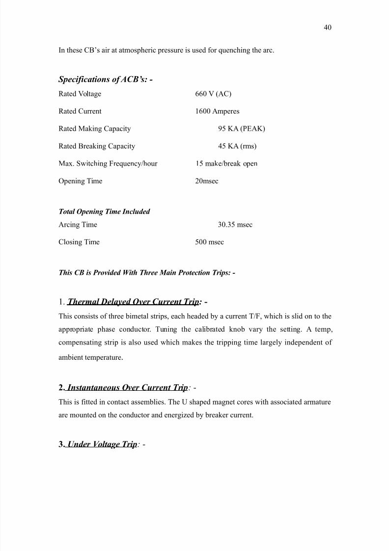
>n these ?*Cs air at atmospheric pressure is used for quenchin the arc.
S/!&!at%'$ %& ACB3$: -
;ated oltae 660 /2?
;ated ?urrent '600 2mperes
;ated 8akin ?apacit# ( I2 /PF2I
;ated *reakin ?apacit# &( I2 /rms
8a4. 1witchin requenc#!hour '( make!break open
@penin Time )0msec
T%ta# O/'' T) I'!#"((
2rcin Time =0.=( msec
?losin Time (00 msec
T,$ CB $ Pr%2(( Wt, T,r Ma' Pr%t!t%' Tr/$: -
'. T,r)a# D#a1( O2r C"rr't Tr/:
This consists of three bimetal strips$ each headed b# a current T!$ which is slid on to the
appropriate phase conductor. Tunin the calibrated knob var# the settin. 2 temp$
compensatin strip is also used which makes the trippin time larel# independent of
ambient temperature.
2. I'$ta'ta'%"$ O2r C"rr't Tr/: -
This is fitted in contact assemblies. The 3 shaped manet cores with associated armature
are mounted on the conductor and eneri%ed b# breaker current.
3. U'(r V%#ta Tr/: -
&0
8/9/2019 Guru Nanak Dev Thermal Power
http://slidepdf.com/reader/full/guru-nanak-dev-thermal-power 41/120
>t opens the breaker instantl# if the au4iliar# as main voltae drop to (0B of the rated
coil voltae.
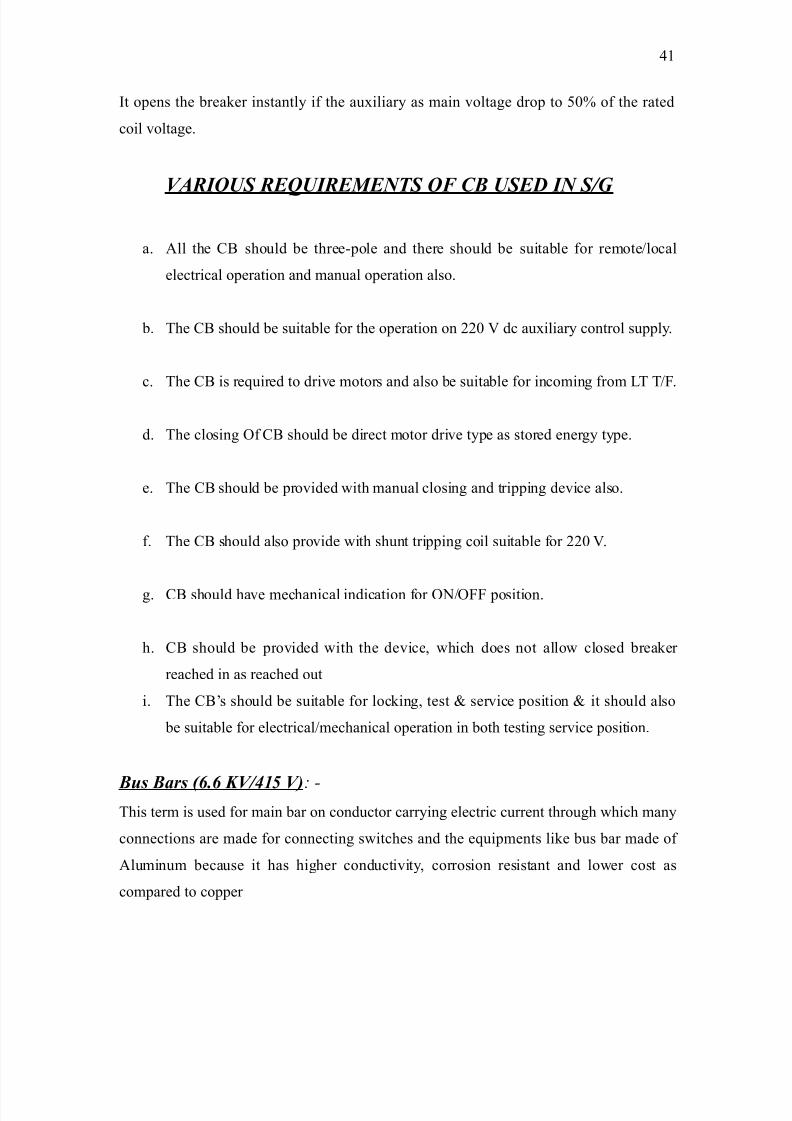
VARIOUS REUIREMENTS OF CB USED IN S7G
a. 2ll the ?* should be three-pole and there should be suitable for remote!local
electrical operation and manual operation also.
b. The ?* should be suitable for the operation on ))0 dc au4iliar# control suppl#.
c. The ?* is required to drive motors and also be suitable for incomin from AT T!.
d. The closin @f ?* should be direct motor drive t#pe as stored ener# t#pe.
e. The ?* should be provided with manual closin and trippin device also.
f. The ?* should also provide with shunt trippin coil suitable for ))0 .
. ?* should have mechanical indication for @N!@ position.
h. ?* should be provided with the device$ which does not allow closed breaker
reached in as reached out
i. The ?*Cs should be suitable for lockin$ test < service position < it should also
be suitable for electrical!mechanical operation in both testin service position.
B"$ Bar$ 46.6 KV789 V5: -This term is used for main bar on conductor carr#in electric current throuh which man#
connections are made for connectin switches and the equipments like bus bar made of
2luminum because it has hiher conductivit#$ corrosion resistant and lower cost as
compared to copper
&'
8/9/2019 Guru Nanak Dev Thermal Power
http://slidepdf.com/reader/full/guru-nanak-dev-thermal-power 42/120
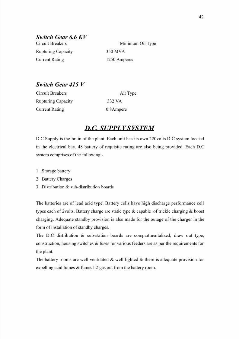
S+t!, Gar 6.6 KV ?ircuit *reakers 8inimum @il T#pe
;upturin ?apacit# =(0 82
?urrent ;atin ')(0 2mperes
S+t!, Gar 89 V
?ircuit *reakers 2ir T#pe
;upturin ?apacit# ==) 2
?urrent ;atin 0.:2mpere
D.C. SUPPLY SYSTEM
D.? 1uppl# is the brain of the plant. Fach unit has its own ))0volts D.? s#stem located
in the electrical ba#. &: batter# of requisite ratin are also bein provided. Fach D.?
s#stem comprises of the followin,-
'. 1torae batter#
) *atter# ?hares
=. Distribution < sub-distribution boards
The batteries are of lead acid t#pe. *atter# cells have hih dischare performance cell
t#pes each of )volts. *atter# chare are static t#pe < capable of trickle charin < boost
charin. 2dequate standb# provision is also made for the outae of the charer in the
form of installation of standb# chares.
The D.? distribution < sub-station boards are compartmentali%ed+ draw out t#pe$construction$ housin switches < fuses for various feeders are as per the requirements for
the plant.
The batter# rooms are well ventilated < well lihted < there is adequate provision for
e4pellin acid fumes < fumes h) as out from the batter# room.
&)
8/9/2019 Guru Nanak Dev Thermal Power
http://slidepdf.com/reader/full/guru-nanak-dev-thermal-power 43/120
'. Dr# cell batteries
). Aead acid batteries
=. 2lkaline cell batteries.
Aead acid cells are of further two t#pes,-
' 2utomobile batter#
) 1tationar# lead acid batter#.
@ut of theses three t#pes of the cells lead acid cell < alkaline cells are rechareable
whereas dr# cells cannot be rechared. >n case of lead acid ell both the electrodes are of
the same material i.e. Aead in case of 2lkaline cell electrodes are of two t#pes,-
'. Nickle$Aead
). >ron$Nickle.
Flectrodes$ which is mostl# used is potassium h#dro4ide. 2s the batter# dischares$
concentration of lead sulphate oes on increasin$ at a specific ravit# for '.)=
discharin stops < the batter# will not provide an# amount of D.? ener#.The batteries
which are used at G.N.D.T.P. >s havin the ratin of 600 2h. >f these havin '0 ratin$ the
batter# supplies 602mp. @f current ratin '0 hours.
*atteries used in the G.N.D.T.P. for the main purpose of,-
'. Fmerenc# lihtenin
). Protection
Two sets of the batteries are used for each circuit. 1o that if one fails second comes in
action.
BATTERY C*ARGING SYSTEM AT G.N.D.T.P.
&=
8/9/2019 Guru Nanak Dev Thermal Power
http://slidepdf.com/reader/full/guru-nanak-dev-thermal-power 44/120
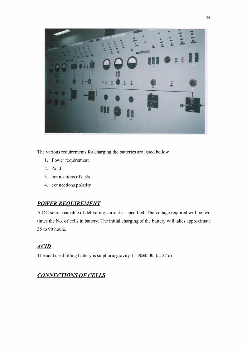
The various requirements for charin the batteries are listed bellow
'. Power requirement
). 2cid
=. connections of cells
&. connections polarit#
POWER REUIREMENT
2 D? source capable of deliverin current as specified. The voltae required will be two
times the No. of cells in batter#. The initial charin of the batter# will takes appro4imate
(( to 0 hours.
ACID
The acid used fillin batter# is sulphuric ravit# '.'00.00(/at )9 c
CONNECTIONS OF CELLS
&&
8/9/2019 Guru Nanak Dev Thermal Power
http://slidepdf.com/reader/full/guru-nanak-dev-thermal-power 45/120
The Qve terminal lu of the cell in one row is connected to the Jve lu of the end cell in
the other row. The connections b!w the two rows ma# be made with the necessar# lenth
of ?3 of the si%e used b!w the switchboard < batter#.
POLARITY OF T*E CONNECTIONS
>tCs ver# important that Qve terminal of the batter# is connected to the Qve lead of the
charin source.
To ascertain the polarit# of the charin leads connected a lamp in the series < dip the
ends in a lass of slihtl# saline water. 1witch on the suppl#. ine bubbles of the as will
be iven off from the Jve lead. The lamp connected in the series eliminates the daner of
accidental short circuit.
C*ARGING EUIPMENT
C*ARGING
*atteries have to be chared occasionall# to restore them to be in workin condition.
Durin the charin D? current is passed throuh the batter# in the direction opposite to
that when the batter# is bein used. ?harin current is usuall# obtained from batter#
charer$ which is the selenium or transformers desined to step up the voltae or down to
suitable values.
BATTREY C*ARGING EUIPMENT
The charin of batter# is done b# a s#stem known as trickle charin unit.
TRICKLE C*ARGING UNIT
loat charer
&(
8/9/2019 Guru Nanak Dev Thermal Power
http://slidepdf.com/reader/full/guru-nanak-dev-thermal-power 46/120
*oost charer
BRIEF DESCRIPTION OF T*E BATTERY C*ARGING
'. loat charer operates on constant voltae mode < maintains the D? output
within Q!-'B of the set value.
). The boost charer operates on constant current mode till the o!p current reaches
set value$ be#ond which it operates in constant current mode.
=. Durin charin or providin the equali%in charer to the batter# the boost
charer operates in constant current mode.
3nder normal runnin condition the D? load is connected across the float
charer < the batteries are also connected across the float charer throuh the D?
contactor < ets the trickle charer from the float charer so that if in case suddenl#
the 2? suppl# fails the batteries will suppl# the D? power to the continuous D? load
< disturbance will not be created. The float charer floats on the D? bus thatCs wh# it
is called float charer. *asicall# the float charer is provided for the continuous Dc
load < at the same time trickle charers the batteries so that when the mains fail the
load demand meet the batter# immediatel#. Now if the batter# ets dischared while
suppl#in the load. To chare the batter# aain boost chare is provided which
boostl# chares up the batter# to the desired level of the voltae.*oth the boost <
float chares are th#irosterised power supplies havin automatic voltae current
reulation features.
BOOST C*ARGER
The workin of the boost charer depends on the voltae of the cells of the batter# i.e.
when the voltae of the a sinle cell of the batter# reaches '.: volts!cell the boost charer
is automaticall# tuned @N 9 starts charin the batter# cells < remains @N till the
voltae reaches ).9 volt!cell i.e. =(.' volt of the total batter#.
The float charer will determine the load voltae. "hen the 2? suppl# is
available both the float charer < the batteries are connected across the D? cont. load.
&6
8/9/2019 Guru Nanak Dev Thermal Power
http://slidepdf.com/reader/full/guru-nanak-dev-thermal-power 47/120
The float charer simpl# converts the 2? suppl# to D? suppl# < feed the continuous Dc
load as well as to float the batteries at ).'6 volts!cell.
1uddenl# if now 2? fails the batteries will come across the Dc load current
requirement. Now when the 2? supplies resumes the boost charer is connected to the
batteries to rechare them with the boost ener#. *oost charer operates in the constant
current mode.
COMPONENTSS OF T*E FLOAT C*ARGER
'. >nput switch
). E;? fuses
=. ?ontractor with thermal overload rela#
&. indication lihts
(. Dc voltmeter < ammeter
WORKING
The circuit "orks on the 2? phase control principle. The 1?; is a semiconductor device
with = terminals i.e. anode cathode ate. The main load current is carried b# the anode$
cathode$ while the control current flows throuh the ate < cathode. ?haracteristics of
the 1?; are such that iot blocks the forward voltae when ate is not supplied with the
anode current. "hile it oes into conduction when ate current reaches a specified level
therefore charin the instant at which the ate current or the pulse is supplied can
control the instant at which the 1?; oes into conduction. @nce the 1?; is triered it
remains in conduction until anode current is reduced to %ero or reverse voltae is applied
anode.Thus chanin the instant of firin of the 1?;. Potentiometer ; ' is used for
ad5ustin the output voltae settin can control the output voltae of the rectifier bride.
The D? output load current is sensed b# the Dc shunt. The sinal proportional to this load
is fed to the controller. >n the event of the load current e4ceeds the rated full load current$
the output voltae starts droppin$ thus limitin the load current. This inherent is
provided in the float charer apart from the back-up.
&9
8/9/2019 Guru Nanak Dev Thermal Power
http://slidepdf.com/reader/full/guru-nanak-dev-thermal-power 48/120
8/9/2019 Guru Nanak Dev Thermal Power
http://slidepdf.com/reader/full/guru-nanak-dev-thermal-power 49/120
8/9/2019 Guru Nanak Dev Thermal Power
http://slidepdf.com/reader/full/guru-nanak-dev-thermal-power 50/120
durin this time. The boost voltae is set to ).'6 volts!cell < would remain constant
within Q!-'B of the set voltae.
There are special desined features which are incorporated in the boost charer
enables it to be used as a float charer so that the dela# cause durin rectif#in the float
charer does not effect the D? suppl# s#stem.
FLOAT C*ARGER
The charer is so called because if floats on the D? bus. The charer is fed from = phase
2c suppl# < ives the D? stabili%ed @!P at rated full load current. The variation in D?
@!P voltae is limited to Q!-'B for 0-'00B load variation < simultaneousl# 2? voltae
variation of Q!-'0B < frequenc# variation of Q!-(B from (0 ER.
RELAYS
;ela# is a device that detects the fault mostl# in the hih voltae circuit. < initiates the
operation of the ?* to isolate the defective section from the rest of the circuit."henever
fault occurs on the power s#stem$ the rela# detects that fault < closes the trip coil circuit.
This results in the openin of the ?* which disconnects the fault# circuit. Thus the rela#
ensures the ensures the safel# of the circuit. equipment from damae which the fault ma#
cause.
PURPOSE OF PROTECTIVE RELAY AND RELAYING
The capital investment involved in a power s#stem for the eneration$ transmission <
distribution if electrical power is so reat that the proper precautions must be taken to
ensure that the equipment not onl# operates as nearl# as possible to peak efficienc# but
also that it is protected from accidents. The normal path of the electric current is from the
power source throuh copper conductors in the enerators$ transformers < transmission
lines to the load < it is confined to this path b# insulation. The insulation however ma#
be broken down either b# effect of temp. < ae or b# a ph#sical accident$ so that the
(0
8/9/2019 Guru Nanak Dev Thermal Power
http://slidepdf.com/reader/full/guru-nanak-dev-thermal-power 51/120
current then follows an abnormal path enerall# known as short-circuit or fault.
"henever this occurs the destructive capabilities of the enormous ener# the power
s#stem ma# be causes e4pensive damae to the equipment$ severe drop in the voltae <
loss of revenue due to interruption of service. 1uch faults ma# be made infrequent b#
ood desin of the power apparatus < lines the provision of protective devices$ such as
sure diverters < round fault neutrali%ers$ but a certain number will occur inevitabl# due
to lihtenin < unforeseen accidental conditions.The purpose of protective rela#s <
rela#in s#stems is to operate correct ?.* so as to disconnect onl# the fault# equipment
from the s#stem as quickl# as possible.
CONSTRUCTION:
2ll the rela#s have followin three essential fundamental elements,
9. SENSING ELEMENT:
1ometime it is also called measurin element. >t is element which is the responsible to
the chane in manitude or phase of the quantit#.
2. COMPARING ELEMENT:
>t is the element which compares the action of the actuatin quantit# of the
rela# with the pre-desined rela# settin. The rela# onl# picks up if the
actuatin quantit# is more than the rela# settin.
3. CONTROL ELEMENT:
"hen the rela# picks up it accomplishes a sudden chane in controlled quantit# such as
closin of the trip coil circuit.
TYPES:-
2ccordin to the conc. < principle of operation rela#s are of followin three t#pes.
('
8/9/2019 Guru Nanak Dev Thermal Power
http://slidepdf.com/reader/full/guru-nanak-dev-thermal-power 52/120
1. THERMAL RELAYS-
The operation of these rela#s depends on the headin effect of the electric current.
2. E.M. ATTRACTION RELAYS-
These are the electromanetic rela#s. The operation of these rela#s depends
on the movement of armature under the influence of attractive forces due to
manetic field up b# current flowin throuh the rela# coil.
3. INDUCTION RELAYS-
The operation of these rela#s depends on the electromanetic induction phenomena. *#
induction$ edd# currents are induced in the 2A in the disc$ free to rotate$ which e4erts
torque on it.
VARIOUS TYPES OF RELAYS USED FOR PROTECTION
ARE:
1. OVER CURRENT RELAY-
>n this protection trip coil is eneri%ed when current in the circuit is '0 times the normal
current. This protection is applied b!w = phases.
2. INSTANTANEOUS RELAY-
The time operation of this rela# is 0.' sec. >t is more effective where impedance b!w the
sources <rela# is small as compared with the impedance of section be operated.
3. LOCKED ROTOR RELAY-
This protection is applied b!w ) phases. >n this protection the trip coil is eneri%ed when
the current usuall# durin startin the current is ( to 6 times the normal current.
&. UNBALANCE PROTECTION,-
()
8/9/2019 Guru Nanak Dev Thermal Power
http://slidepdf.com/reader/full/guru-nanak-dev-thermal-power 53/120
>t protects aainst Jve phase sequence current. The rela# normall# used is an >D8T rela#.
(. EARTH FAULT PROTECTION,-
The s' terminals of = ?.*Cs are connected to = phases ;$$* < second terminals 1) are
connected toether. This form neutral thus connections are star connected. >deall# there is
no current in neutral. *ut if b# an# reason the circuit. 1tart to flow in the neutral the earth
fault occurs < trip coil is eneri%ed thus trippin the ?.*Cs.
. UNDER VOLTAGE RELAY-
>n this protection the coil is eneri%ed when the voltae drops to 90B of the normal
value. >tCs app. >s reverse time under voltae protection of a.c circuit capacitor$ rectifier <
m!c such as induction motorS
(=
8/9/2019 Guru Nanak Dev Thermal Power
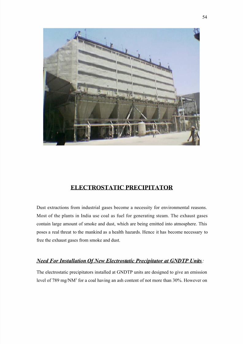
http://slidepdf.com/reader/full/guru-nanak-dev-thermal-power 54/120
8/9/2019 Guru Nanak Dev Thermal Power
http://slidepdf.com/reader/full/guru-nanak-dev-thermal-power 55/120
actual testin it has been found that emission level from F1PCs was about =.0 m!8 =. The
hih level of emission is due to the fact that coals burnt in the boiler have much hiher
ash content than what boilers are desined for. The pollution control board of Pun5ab
Govt. has specified an emission level of =:0 m!8 = from chimne#. >n order to achieve
this new emission level additional F1PCs have been installed at GNDTP *athinda.
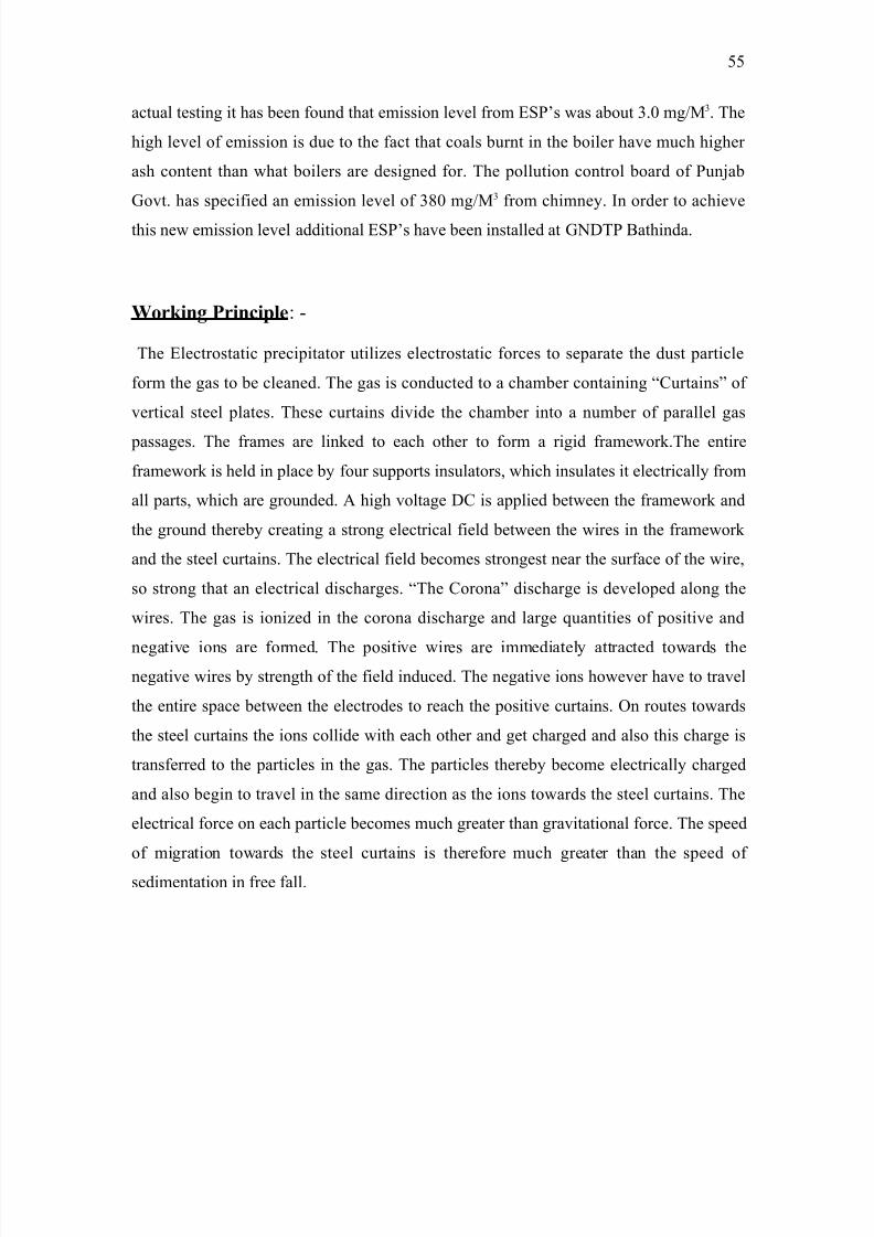
Wo$)+% P$+5+6", -
The Flectrostatic precipitator utili%es electrostatic forces to separate the dust particle
form the as to be cleaned. The as is conducted to a chamber containin M?urtainsL of
vertical steel plates. These curtains divide the chamber into a number of parallel as
passaes. The frames are linked to each other to form a riid framework.The entire
framework is held in place b# four supports insulators$ which insulates it electricall# from
all parts$ which are rounded. 2 hih voltae D? is applied between the framework and
the round thereb# creatin a stron electrical field between the wires in the framework
and the steel curtains. The electrical field becomes stronest near the surface of the wire$
so stron that an electrical dischares. MThe ?oronaL dischare is developed alon the
wires. The as is ioni%ed in the corona dischare and lare quantities of positive and
neative ions are formed. The positive wires are immediatel# attracted towards the
neative wires b# strenth of the field induced. The neative ions however have to travel
the entire space between the electrodes to reach the positive curtains. @n routes towards
the steel curtains the ions collide with each other and et chared and also this chare is
transferred to the particles in the as. The particles thereb# become electricall# chared
and also bein to travel in the same direction as the ions towards the steel curtains. The
electrical force on each particle becomes much reater than ravitational force. The speed
of miration towards the steel curtains is therefore much reater than the speed of
sedimentation in free fall.
((
8/9/2019 Guru Nanak Dev Thermal Power
http://slidepdf.com/reader/full/guru-nanak-dev-thermal-power 56/120
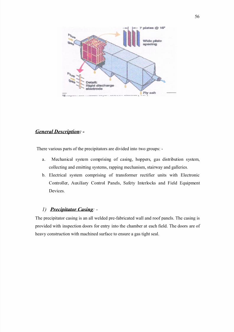
G'ra# D$!r/t%': -
There various parts of the precipitators are divided into two roups, -
a. 8echanical s#stem comprisin of casin$ hoppers$ as distribution s#stem$
collectin and emittin s#stems$ rappin mechanism$ stairwa# and alleries.
b. Flectrical s#stem comprisin of transformer rectifier units with Flectronic
?ontroller$ 2u4iliar# ?ontrol Panels$ 1afet# >nterlocks and ield Fquipment
Devices.
1) Pr!/tat%r Ca$' : -
The precipitator casin is an all welded pre-fabricated wall and roof panels. The casin is
provided with inspection doors for entr# into the chamber at each field. The doors are of
heav# construction with machined surface to ensure a as tiht seal.
(6
8/9/2019 Guru Nanak Dev Thermal Power
http://slidepdf.com/reader/full/guru-nanak-dev-thermal-power 57/120
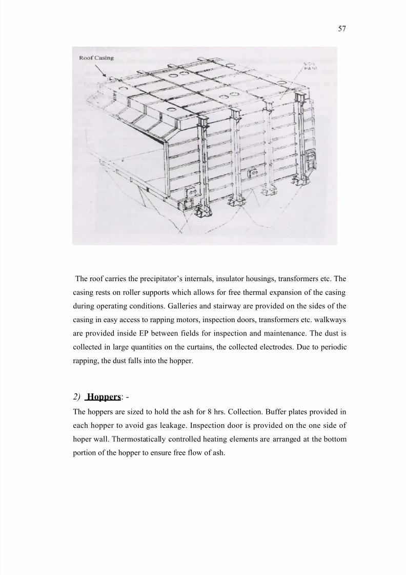
The roof carries the precipitatorCs internals$ insulator housins$ transformers etc. The
casin rests on roller supports which allows for free thermal e4pansion of the casin
durin operatin conditions. Galleries and stairwa# are provided on the sides of the
casin in eas# access to rappin motors$ inspection doors$ transformers etc. walkwa#s
are provided inside FP between fields for inspection and maintenance. The dust is
collected in lare quantities on the curtains$ the collected electrodes. Due to periodic
rappin$ the dust falls into the hopper.
2) Ho66$, -
The hoppers are si%ed to hold the ash for : hrs. ?ollection. *uffer plates provided in
each hopper to avoid as leakae. >nspection door is provided on the one side of
hoper wall. Thermostaticall# controlled heatin elements are arraned at the bottom
portion of the hopper to ensure free flow of ash.
(9
8/9/2019 Guru Nanak Dev Thermal Power
http://slidepdf.com/reader/full/guru-nanak-dev-thermal-power 58/120
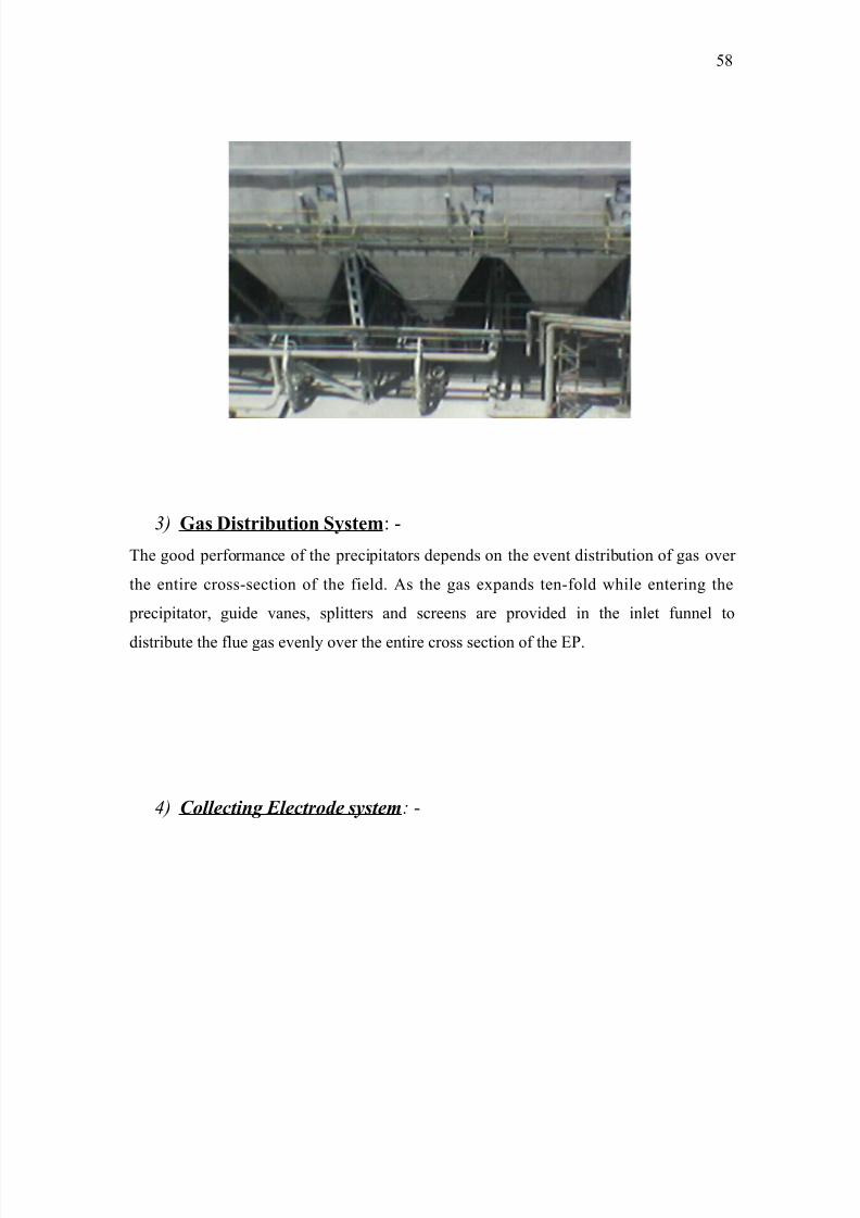
3) G! D+$+78+o S9:, -
The ood performance of the precipitators depends on the event distribution of as over
the entire cross-section of the field. 2s the as e4pands ten-fold while enterin the
precipitator$ uide vanes$ splitters and screens are provided in the inlet funnel to
distribute the flue as evenl# over the entire cross section of the FP.
4) C%##!t' E#!tr%( $1$t): -
(:
8/9/2019 Guru Nanak Dev Thermal Power
http://slidepdf.com/reader/full/guru-nanak-dev-thermal-power 59/120
The collectin plates are made of '.6 mm cold rolled mild steel plate and shaped in piece
b# roll formin. The collectin plates and shaped in one piece b# roll formin. The
collectin electrode has unique profile with a special confiuration on its lonitudinal
edes. This profile is desined to ive riidit# and to contain the dust in quiescent %one
free from re-entertainment+ collectin plates are provided with hooks at their top ede for
suspension. The hooks enae in slot of the supportin anle. 2ll the collectin plates in
arrow are held in position b# a shock bar at the bottom. The shock bars are spaced b#
uides.
iure, - TYPICAL COLLECTION PLATES
5) E)tt' E#!tr%( $1$t): -
The most essential part of precipitators is emittin electrode s#stem. our insulators
support this$ the frames for holdin the emittin electrodes are located centrall# between
collectin electrodes curtains. The entire dischare frames are welded to form a riid bo4
like structure. The emittin electrodes are kept between the frames.
(
8/9/2019 Guru Nanak Dev Thermal Power
http://slidepdf.com/reader/full/guru-nanak-dev-thermal-power 60/120
F: R( &ra) ($!,ar #!tr%( ($'
6) Ra//' S1$t): -
;appin mechanism is provided for collectin and emittin electrodes. Geared motors
drive the rappin mechanism. The rappin s#stem emplo#s tumblin hammers$ which are
mounted on a hori%ontal shaft. 2s the shaft rotates slowl# the hammers which are
mounted on a hori%ontal shaft. 2s the shaft rotates slowl# the hammers tumble on theshock bar!shock$ which transmits blow to the electrodes. @ne complete revolution of the
rappin shaft will clean the entire field. The rapper prorammer decided the frequenc# of
rappin. The tumblin hammers disposition and the periodicit# of the rappin are
selected in such a wa# that less than )B of the collectin area is rapped at one time. This
avoids re-entertainment of dust and puffin at the stock outlet.
60
8/9/2019 Guru Nanak Dev Thermal Power
http://slidepdf.com/reader/full/guru-nanak-dev-thermal-power 61/120
The rappin shaft of emittin electrodes s#stem is electrical isolated from the eared
motor driven b# a shaft insulator. The space around the shaft insulator is continuousl#
heated to avoid condensation.
ollowin 2re the 8odules for the @utoin eeders, -
• Eopper heater for each field
• 1upport insulator heaters.
• 1haft insulator heaters.
• ?ollectin electrode-rappin motor for each field.
• Fmittin electrode rappin motor for each filed.
*, V%#ta Tra'$&%r)r R!t&r 4*VR5 +t, E#!tr%'! C%'tr%##(
4EC5: -
The rectifier supplies the power for as particle charin and collection. The basic
function of the F? is to feed the precipitator with ma4imum power input under constant
current reulation should there be an# flash between collectin and emittin electrodes$
the F? will sense the flash and quickl# react b# brinin the input period voltae to %ero
6'
8/9/2019 Guru Nanak Dev Thermal Power
http://slidepdf.com/reader/full/guru-nanak-dev-thermal-power 62/120
and blockin it for a specific period. 2fter the ioni%ed ases are cleaned and the dielectric
strenth restored$ the control will quickl# brin back the power to a present value and
raise it to the oriinal non-sparkin level. Thus the F? ensure the electrical disturbance
within precipitator. ;eulated 2? power from F? is fed to the primar# of the
transformer$ which is stepped up and rectified to ive a full wave power output. The
transformer is mounted on roof of the precipitator while the F? is located in an air
conditional room.
A";#ar1 C%'tr%# Pa'# 4ACP5: -
The 2?P houses the power and circuits required for eneri%in rappin motor and
heatin elements of the precipitator. 2?P controls each as path. The complete 2?P is of
modular t#pe with individual module for each feeder. Fach module houses the power and
control circuit with meters. Push buttons$ witches and indicatin lamps are mounted on
the door of the compartments.
Ma;)<' T, Pr&%r)a'! OF ESP : -
The performance of the F1P is influenced b# a number of factors man# of which ma# be
controllable. >t should be the aim of ever# operator to ma4imi%e the performance b#
5udiciousl# ad5ustin the controllable variables.
C#a'' O& E#!tr%($: -
The performance of the F1P depends on the amount of electrical power absorbed b# the
s#stem. The hihest collection efficienc# is achieved when ma4imum possible electric
power for a iven set of operatin conditions is utili%ed on the fields. Too thick a dust
la#er on the collectin plates will lead to drop in the effective voltae$ which
consequentl# reduces the collection efficienc#. >t also leads to unstable to unstable
operatin conditions. Therefore the rappin s#stem of collectin and emittin electrodes
should be kept in perfectl# workin condition. 2ll the rappin motors have been
prorammed to achieve the optimum efficienc#.
A$, *%//r E2a!"at%': -
6)
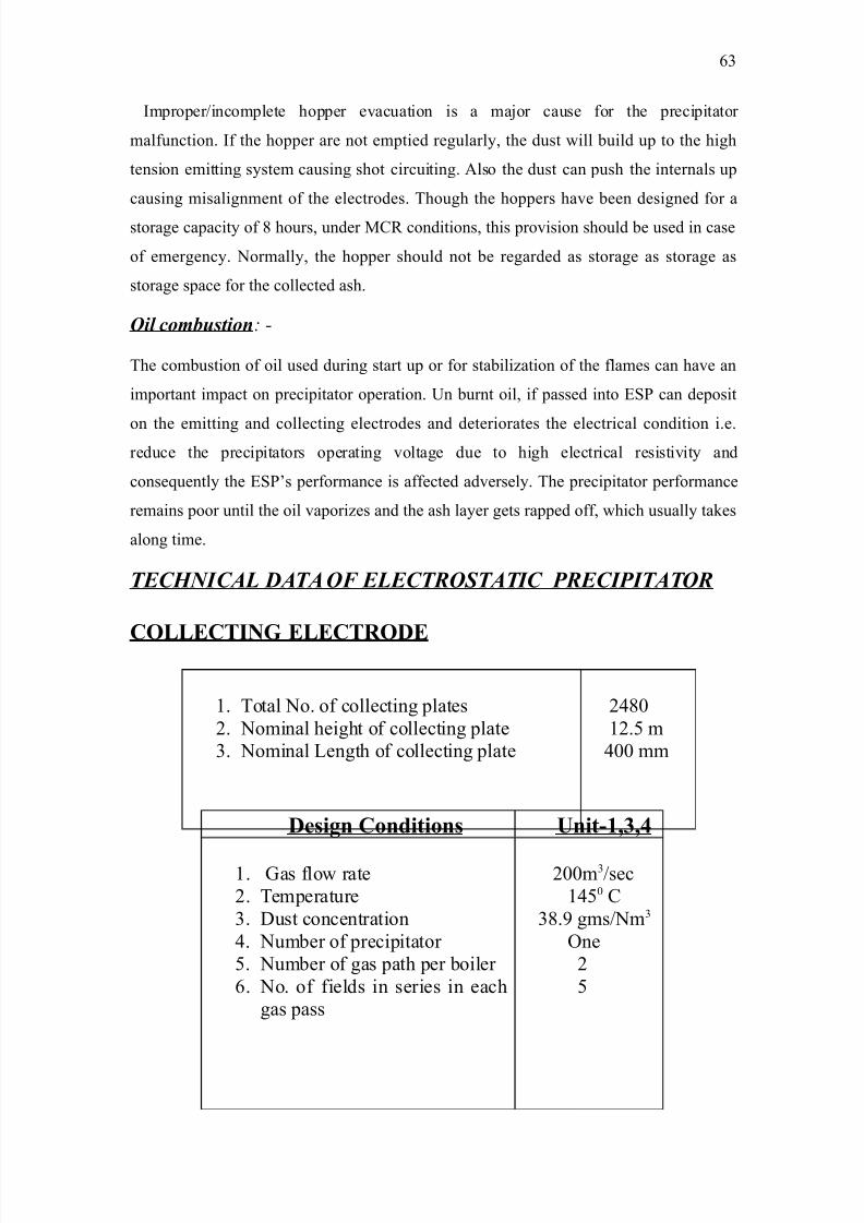
8/9/2019 Guru Nanak Dev Thermal Power
http://slidepdf.com/reader/full/guru-nanak-dev-thermal-power 63/120
>mproper!incomplete hopper evacuation is a ma5or cause for the precipitator
malfunction. >f the hopper are not emptied reularl#$ the dust will build up to the hih
tension emittin s#stem causin shot circuitin. 2lso the dust can push the internals up
causin misalinment of the electrodes. Thouh the hoppers have been desined for a
storae capacit# of : hours$ under 8?; conditions$ this provision should be used in case
of emerenc#. Normall#$ the hopper should not be rearded as storae as storae as
storae space for the collected ash.
O# !%)="$t%': -
The combustion of oil used durin start up or for stabili%ation of the flames can have an
important impact on precipitator operation. 3n burnt oil$ if passed into F1P can deposit
on the emittin and collectin electrodes and deteriorates the electrical condition i.e.reduce the precipitators operatin voltae due to hih electrical resistivit# and
consequentl# the F1PCs performance is affected adversel#. The precipitator performance
remains poor until the oil vapori%es and the ash la#er ets rapped off$ which usuall# takes
alon time.
TEC*NICAL DATA OF ELECTROSTATIC PRECIPITATOR
COLLECTING ELECTRODE
'. Total No. of collectin plates
). Nominal heiht of collectin plate
=. Nominal Aenth of collectin plate
)&:0
').( m
&00 mm
D+% Co;++o U+1,3,4
'. Gas flow rate
). Temperature
=. Dust concentration
&. Number of precipitator
(. Number of as path per boiler
6. No. of fields in series in each
as pass
)00m=!sec
'&(0 ?
=:. ms!Nm=
@ne
)
(
6=
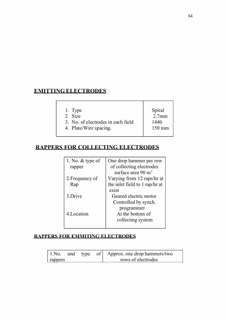
8/9/2019 Guru Nanak Dev Thermal Power
http://slidepdf.com/reader/full/guru-nanak-dev-thermal-power 64/120
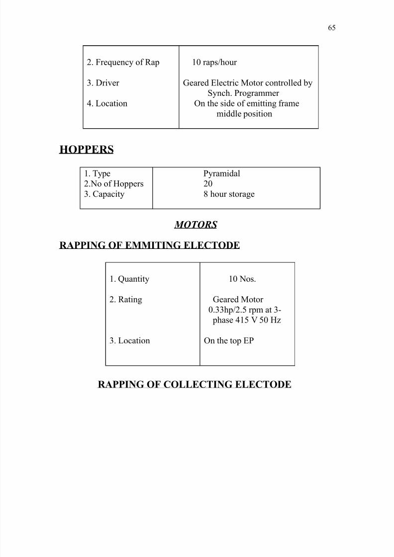
8/9/2019 Guru Nanak Dev Thermal Power
http://slidepdf.com/reader/full/guru-nanak-dev-thermal-power 65/120
). requenc# of ;ap
=. Driver
&. Aocation
'0 raps!hour
Geared Flectric 8otor controlled b#
1#nch. Prorammer @n the side of emittin frame
middle position
HOPPERS
'. T#pe
).No of Eoppers
=. ?apacit#
P#ramidal
)0
: hour storae
MOTORS RAPPING OF EMMITING ELECTODE
'. Kuantit#
). ;atin
=. Aocation
'0 Nos.
Geared 8otor
0.==hp!).( rpm at =-
phase &'( (0 E%
@n the top FP
RAPPING OF COLLECTING ELECTODE
6(
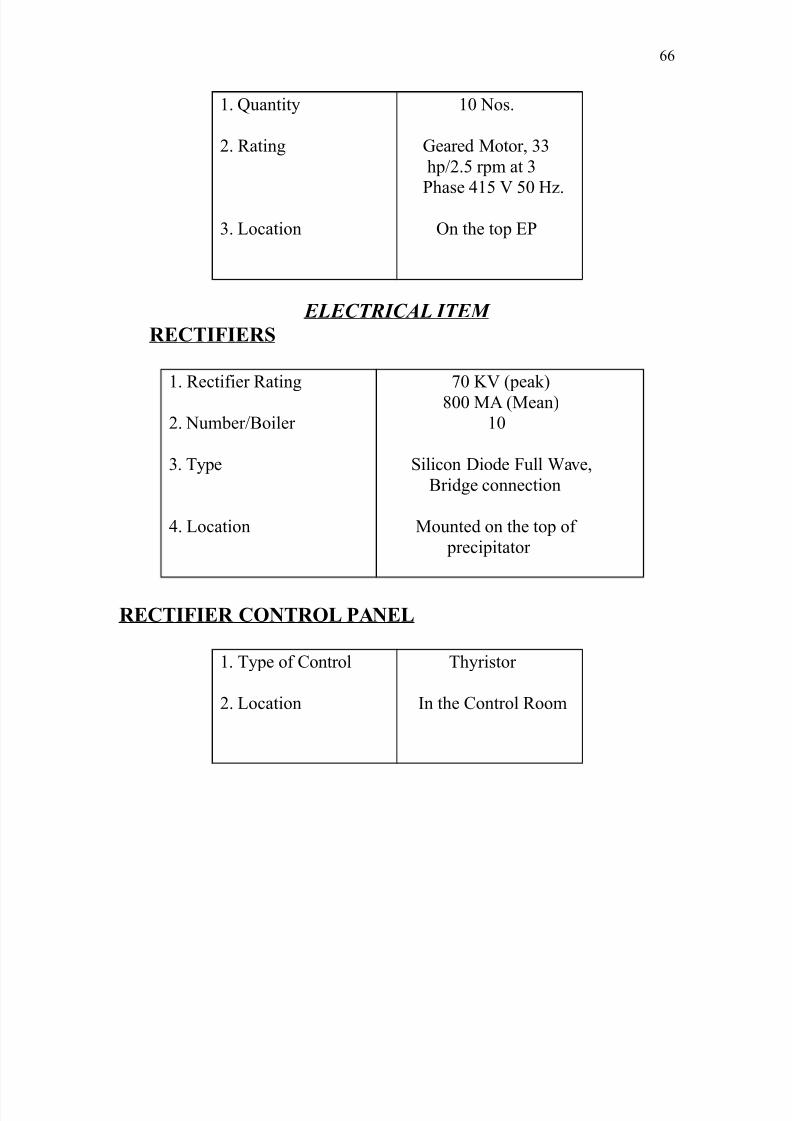
8/9/2019 Guru Nanak Dev Thermal Power
http://slidepdf.com/reader/full/guru-nanak-dev-thermal-power 66/120
'. Kuantit#
). ;atin
=. Aocation
'0 Nos.
Geared 8otor$ ==
hp!).( rpm at =
Phase &'( (0 E%.
@n the top FP
ELECTRICAL ITEM
RECTIFIERS
'. ;ectifier ;atin
). Number!*oiler
=. T#pe
&. Aocation
90 I /peak
:00 82 /8ean
'0
1ilicon Diode ull "ave$
*ride connection
8ounted on the top of
precipitator
RECTIFIER CONTROL PANEL
'. T#pe of ?ontrol
). Aocation
Th#ristor
>n the ?ontrol ;oom
66
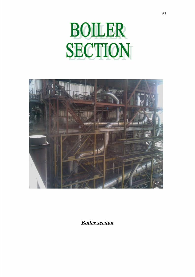
8/9/2019 Guru Nanak Dev Thermal Power
http://slidepdf.com/reader/full/guru-nanak-dev-thermal-power 67/120
B%#r $!t%'
69
8/9/2019 Guru Nanak Dev Thermal Power
http://slidepdf.com/reader/full/guru-nanak-dev-thermal-power 68/120
The steam eneratin unit is desined to meet the nominal requirements of ''08" turbo
enerator set. The unit is desined for a ma4imum continuous ratin of =9( tones!hr. at a
pressure of '=k!cm) and a steam temperature of (&00°?. the reheated steam flows at
8?; =)E tones!hr. at the feed water temp at 8?; is )&00°?. The unit is a balance
drauht dr# bottom+ sinle drum natural circulation$ vertical water tube t#pe$ construction
with skin casin and a sinle reheat s#stem. The furnace is arraned for dr# ash dischare
and is fitted with burners located at the four corners. Fach corner burner comprises coal$
vapour oil and secondar# air compartments. The unit is provided with three ball mills and
arraned to operate with intermediate cool powder bunker. The steam super heater
consists of & staes i%. ?eilin$ convection$ platen and final superheated. The ceilin
super heated forms the roof of the furnace and hori%ontal pass and finishes as the rear
wall of the second pass. The convection super heated is made up of hori%ontal banks
located in the second pass. "hile the platens are located at the furnace e4it$ the portion
above the furnace nose encloses the final superheated reheater are in two staes$ first
stae is the triflu4 heat e4chaners located in the second pass$ which absorbs heat from
superheated steam as well as from the flue ases. The second stae is e4it reheater
located in the hori%ontal pass as pendant tubular loops.
/a The flue as for dr#in the cool in the mills is tapped off after the triflu4 heat
e4chaners. The damper located in the hot flue ases pipe leadin to mill controls the
quantit#. ?ontrol the circulatin vapour of the mill entr# effect temperature control.
>mmediatel# after the triflu4 heat e4chaner$ the air heaters and economi%ers are located.
The air heater is in ) staes.
/b The hot air for combustion from air heater stae ) is led into the common wind bo4
located on the sided of the furnace. & cool air mi4ed pipes from pulveri%ed coal bounders
are connected to & cool burnersC no%%le at the corners. There will be totall# '6 coal
no%%les. & located in each corner. @il uns will be located in the secondar# air no%%le for
coal burnin. The turn down ratio of the uns will be so selected that it will be possible to
use them also for pulveri%ed fuels flame stabili%ation while operatin under load below
the control point.
6:
8/9/2019 Guru Nanak Dev Thermal Power
http://slidepdf.com/reader/full/guru-nanak-dev-thermal-power 69/120
/c Take into consideration the hih B ae of ash and the relativel# poor qualit# of coal
due reards has been paid to wide pitchin the tubes and to the as velocit# across the
heatin surface areas. >n order to insure reliable and continuous operation sample sot
blowin equipment is provided. There are short retractable steam root blowers provide at
the top of furnace full# retractable rotar# t#pe blowers are located for cleanin of the
secondar# super heater and final heater partl# retractable steam blowers are arraned for
the hori%ontal reheater and super heaters in the second pass. The steam root blowers are
electricall# operated.
/d ;oot blowin no%%les usin blow down from boilers drum are provide for the
cleanin of areas around the burners no%%les %one for dislodin of sla boulder if an# in
the bottom ash hopper in the furnace.
/e Two D fans are provided per boiler. The D fans are of the a4ial t#pe driven b#
constant speed motor. The reulation of quantit# and pressure is done b# inlet vane
control. The flue ases are sucked throuh the mechanical and electrostatic precipitators
b# >.D. fans and delivered into the chimne#. Two >.D. fans are provided for each boiler
and the# are of the a4ial t#pe driven b# constant speed motors. >nlet vane control effects
the capacit# chane with reference to load. *oth the >.D. and D fans have been
dimensioned takin into account the minimum marins of '(B on volume and =)B on
pressure.
S/!&!at%'
• 8anufacturer *.E.F.A
• 8a4imum continuous ratin =9(tones!hr.
• 1uper heater outlet pressure '=k !cm)
• ;eheater outlet pressure ==.: k!cm)
• inal super heater temperature (&0 de.c
• eed water temperature )&0de.c
• Ffficienc# :6B /stae-'
:9B /stae-)
• ?oal consumption per da# '(00 tones
6
8/9/2019 Guru Nanak Dev Thermal Power
http://slidepdf.com/reader/full/guru-nanak-dev-thermal-power 70/120
AS* SYSTEM
BOTTOM AS* SYSTEM
The ash deposited at the bottom of the furnace is collected in a water impounded hopper
where a continuous flow of water is maintained to limit the temperature of ash inside the
hopper. The bottom ash cleanin is done in ever# c#cle of : hours. The bottom ash
s#stem is local manuall# operated. @n openin of feed ate ash is allowed to dischare
into a double roll linder rinder where it is rounded to smaller si%e$ which can be
transported throuh the pipe line below the linker rinder there is a venturi which sucks
the round ash the vaccum created at the venturi throat b# the flow of hih pressure water
tapped. Dawn stream of the dischare of the ash water pumps. The pressure recovered at
the end of venturi is adequate to conve# the slurr# to disposal area.
STEAM CYCLE
The desin of the power c#cle based on the modern concept$ where a unit consists of a
steam enerator with its independent firin s#stem tied to the steam eneration. The
steam enerator is desined for ma4imum continuous ratin of =9(-tonnes!hr. and steam
Pressure of '=-k!cm) at temperature of (&0°? respectivel#. The steam enerator is
desined to suppl# to a sinle reheat t#pe condensin steam turbine with a : non
reulated e4traction points of steam for headin the condensate and feed water. The
steam c#cle can be classified into the followin three divisions, -
a. 8ain steam /b ;eheat steam /c e4traction steam
4a5MAIN STEAM
1aturated steam from the steam enerator drum is led to the super heater bank to heat if
up to (&0°? saturated steam from the drum is led to the ceilin super hearter /between
1EE' and 1EE) from ceilin super steam oes to convection super heater /between
1EE) and 1EE= the first reulated infection for at temperature takes place after
convection super heater /between 1EE and 1EE'0. *efore entr# to final super heater
90
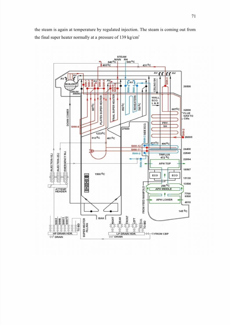
8/9/2019 Guru Nanak Dev Thermal Power
http://slidepdf.com/reader/full/guru-nanak-dev-thermal-power 71/120
the steam is aain at temperature b# reulated in5ection. The steam is comin out from
the final super heater normall# at a pressure of '= k!cm)
9'
8/9/2019 Guru Nanak Dev Thermal Power
http://slidepdf.com/reader/full/guru-nanak-dev-thermal-power 72/120
Temperature takes place after convection super heater /between 1EE and 1EE'0.
*efore entr# to final super heater the steam is aain at temperature b# reulated in5ection.
The steam is comin out from the final super heater normall# at a pressure of '= k!cm )
at a temperature of (&0o?. This steam is feed to the control valve. >n each of the two live
steam lines there is one turbine side main steam stop valve and one hih pressure quick
closin valve alon with two control valves.
4=5 EXTRACTION STEAM
1team for heatin of the condenser and the feed steam is e4tracted from : non reulated
e4traction points from the turbine. Eeatin is carried out in five staes of A.P. heaters$
one deareatin heater and in two E.P. heaters e4traction '$)$=$ is taken from A.P. turbine.
F4traction &$ ($ 6 and 9 are taken from 8.P. turbine. F4traction : is obtained from ?.;.E.
line first and second stae of heatin is done b# two sets of twin low-pressure heaters
mounted directl# in the A.P. casin of the turbine. F4traction =$& and ( are connected to
the deaereatin heater placed above feed water storae tank 9 th and :th e4traction steam is
fed to the vertical E.P. heaters respectivel#.
4C5 RE*EAT STEAM
F4it steam from the E.P. turbine is taken back to the reheater section of the steam
eneratin unit. ;eheatin is done in two staes both b# flue as and b# super heated
steam. The steam to be reheated is first pass throuh the triple-heated e4chaner$ where
super heated steam is used as the heatin media. The steam is finall# reheated in final
reheaters /;EE= ;EE& and ;EE( suspended in the hori%ontal pass of the furnace.
;eheat steam at a normal pressure of =6.& k!cm) at a temperature of (&0 °? respectivel#
is fed to the 8.P. c#linder b# two hot reheat steam pipes throuh strainers and combined
stop and interceptor valves. >n each of the cold reheat steam lines from E.P. c#linder a
non-return valve is operated b# oil pressure is provided.
9)
8/9/2019 Guru Nanak Dev Thermal Power
http://slidepdf.com/reader/full/guru-nanak-dev-thermal-power 73/120
MILLING CIRCUIT
The crushers crush the coal upto the dia of )0 mm. This coal comes to the raw coal
bunker throuh conve#er belts. This coal is fed into the ball mill throuh chain feeder$
operated b# motor. >n drum the steel balls are used to make it pulveri%ed. 2t one end coal
enters the mill and from the other end pulveri%ed coal is sucked b# vapour fan. The
pulveri%ed coal is used for burnin in the furnace. @n its wa# the p.c. /pulveri%ed coal
bunker$ it oes from classifier and c#clone separator function of classifier is to use the
coal for burnin coal which could not pass the classifier$ is collected on the ravit#
damper. "hen the weiht of this coal is enouh$ ravit# damper is opened because of the
weiht of the coal and this coal oes back to mill throuh run back pipin and is further
pulveri%ed. >n c#clone separator much finer particles of coal is stored in P.?. bunker
because of centrifual force. This coal is fed to the P.?. bunker throuh the warm feeder.
Throuh warm feeder$ we can collect the pulveri%ed coal in an# of the P.?. bunker. "arm
feeder runs with the help of motor and earbo4.
COAL PULVERI>ING MILL
?oal mill pulveri%es the raw coal into a fine powder before it is burnt in the boiler
furnace. The pulveri%in of coal is achieved with the impact of fallin steel balls$
weihin ().( tones contained in the mill drum rotatin at a slow speed of '9.( rpm. The
raw coal is dried before pulveri%in with inert hot flue ases tapped from the boiler.
Three coal mills each havin a pulveri%in capacit# of )9 tones per hours are provided
for one unit.
1pecification
Numbers Three per unit
T#pe Drum ball
;ated output =0-=) tonnes!hr.
9=
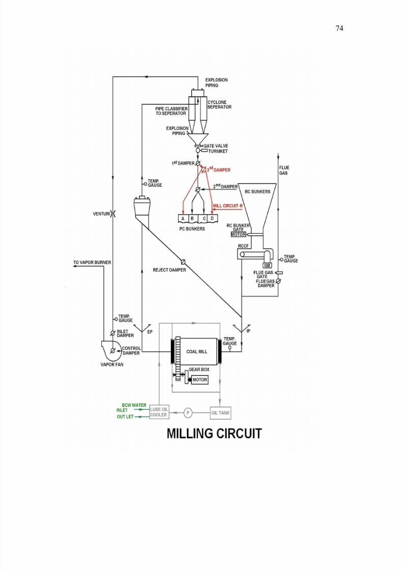
8/9/2019 Guru Nanak Dev Thermal Power
http://slidepdf.com/reader/full/guru-nanak-dev-thermal-power 74/120
9&
8/9/2019 Guru Nanak Dev Thermal Power
http://slidepdf.com/reader/full/guru-nanak-dev-thermal-power 75/120
TURBINE SECTION
9(
8/9/2019 Guru Nanak Dev Thermal Power
http://slidepdf.com/reader/full/guru-nanak-dev-thermal-power 76/120
The turbine is the prime mover for the enerator in the power plant Different t#pes of
steam turbines used in thermal power plants$ but the ones. "hich are used at G.N.D.T. P.
are cateori%ed as follows
1.No. T#pe of Turbine Turbine at G.N.D.T.P.
'. Eori%ontal!vertical Eori%ontal
). 1inle!multi c#linder 8ulti c#linder
=. ?ondensin!non condensin condensin
&. ;eheat! non-reheat ;eheat
(. ;eenerative!non reenerative ;eenerative
6. "ith b# pas!without b# pass with b# pass /stae-'
"ithout b# pass /stae-)
BASIC WORKING OF TURBINE
irst of all the turbine is run on ear motor with the help of e4citer. 2t that time steam is
kept on recirculatin with the help of b# pass valve. "hen the pressure of steam is
increased to on optimum level and turbine acquires a particular rpm then steam is
introduced in the E.P. /hih-pressure c#linder first. The temperature of steam at entrance
is (&0°? and pressure is about '= I!cm). 2fter doin its work on the E.P. Turbine$ the
steam is taken out for reheatin rated temperature of steam at reheater inlet is =60 °?. The
temperature of steam is increased upto (=(°? in the boiler shell and steam is aain
introduced in 8.P /8edium pressure turbine. 2fter 8.P.turbine$ the steam is passed on
to A.P. /Aow-pressure turbine. This process helps the turbine to reach the speed of =000
rpm. 2fter A.P. turbine$ the steam is condensed in condenser$ build below the turbine unit.
The condenser contains a number of brass tubes throuh which coolin out from A.P.
turbine it comes in contact with colder brass tubes then steam et transformed into water.
This water et collected in E@T "FAA 5ust below the condenser. rom here the hot
96
8/9/2019 Guru Nanak Dev Thermal Power
http://slidepdf.com/reader/full/guru-nanak-dev-thermal-power 77/120
water is aain pumped with the help of condensate pumps. The coolin water is used to
condense steam ets heated up and is cooled b# fallin from coolin tower. This
completes the processin of steam throuh turbine and condenser.
ROTOR OF TURBINE
2ll the rotors are manuall# b# means of riid couplin$ includin the rotors of the
enerator. The speed of whole s#stem of rotor lies in the followin ranes of the speed at
the operatin conditions, -
1<(( o 2((( $6: B noticed on the 8.P. and A.P. rotors and enerators.
23'( $6: B noticed on E.P. rotor.
1 . BEARING OF ROTORS
The a4ial load of the entire s#stem of rotors is taken up b# a double-sided a4ial bearin
located in the bearin stand between the E.P. and 8.P casin. These are two protections
mounted near the a4ial bearin one h#dro chemical and one electromanetic$ which fouls
the turboset durin the non-permissible movement of the rotor.
The rotors are placed on radial bearin which are machined to elliptical shape. urther
scrappin operations or chane top and side clearances and chane in temperature of oil$
influence the oil wede and the position of the 5ournal bearin to maintain the same
condition as e4isted durin the initial assembl#.
>n the lower half of bearin a hollow roove is provided in the babbit metal throuh
which oil the supplied throuh a drilled hole throuh E.P. 5ackin oil pumps.
The hih-pressure oil rotors are lifted in the bearin so that an# scrappin of the bearin
is prevented.
99
8/9/2019 Guru Nanak Dev Thermal Power
http://slidepdf.com/reader/full/guru-nanak-dev-thermal-power 78/120
2. TURBINE CASING
The hih-pressure part of turbine is consisted of two-concentric hori%ontal casin. >nner
casin is connected in such a wa# to the other casin that it enables to e4pand in all
direction. The no%%les are attached to the inner casin. The steam pipe is connected to the
condensers and the condensers are supported b# sprins. The casins are inter connected
b# the s#stem of uide ke#s throuh bearin pedestals in such a wa# that thermal
e4pansion of casin does not destro# the various parts of turbine.
The displacement-bearin pedestal between 8.P. and E.P parts is measured b# the
electromanetic pick up. This valve is about of '( mm to prevent deformation at the
casin. >t is ver# important that slidin part clean lubricated and free from ha%ard for
connectin parts bolts elements. The heatin of bolts before tihtenin up and before the
lockin presents. The flanes of 8.P. and E.P. casins are desined to heat up b# steam
durin the startin up of turbo boost b# which the difference in temperature between the
c#lindrical position of the casin flanes and connected bolts is reduced to limited
deformation. The thermo couples are used for measurin temperatures. The thermo
couple is partiall# connected to the indicated apparatus. ?oolin fluid is enerall# used
for reducin the temperature of various parts.
9:
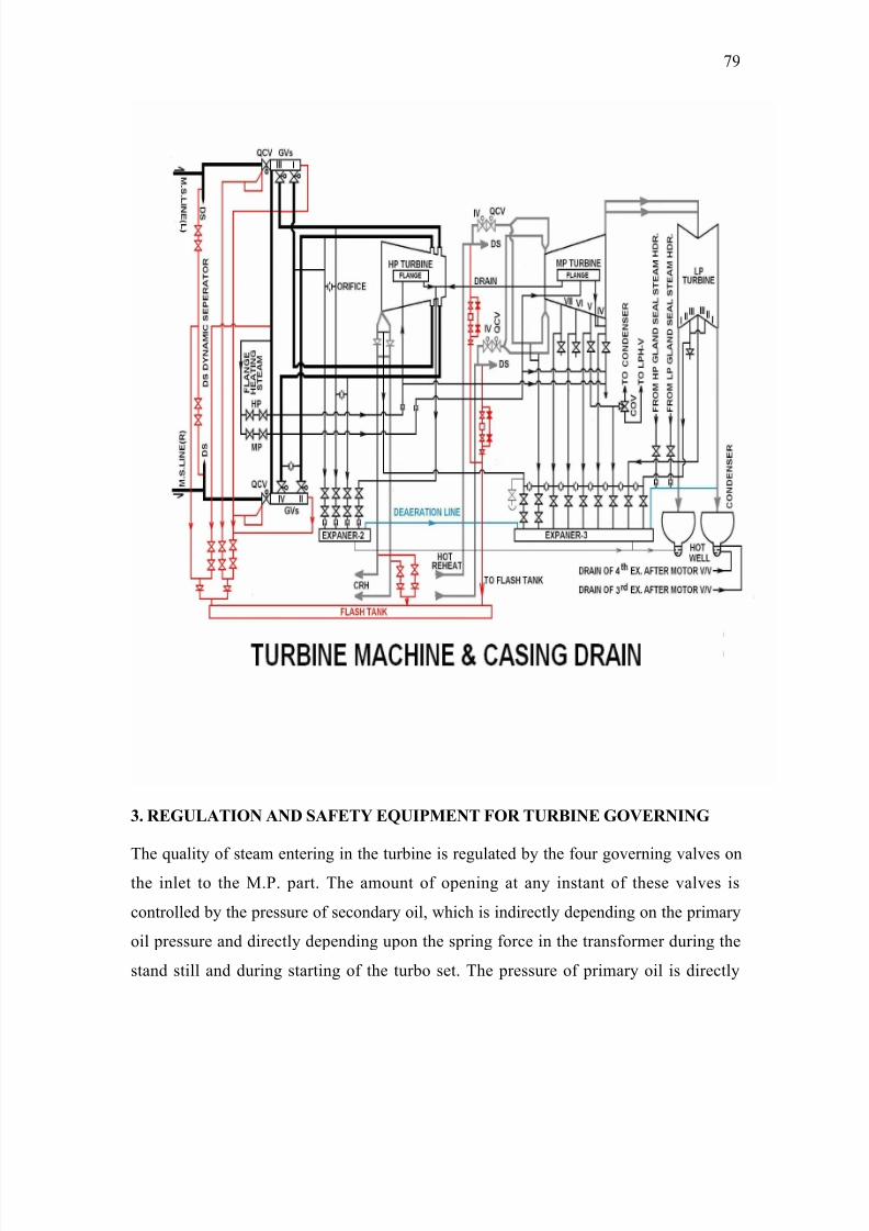
8/9/2019 Guru Nanak Dev Thermal Power
http://slidepdf.com/reader/full/guru-nanak-dev-thermal-power 79/120
3. REGULATION AND SAFETY E=UIPMENT FOR TURBINE GOVERNING
The qualit# of steam enterin in the turbine is reulated b# the four overnin valves on
the inlet to the 8.P. part. The amount of openin at an# instant of these valves is
controlled b# the pressure of secondar# oil$ which is indirectl# dependin on the primar#
oil pressure and directl# dependin upon the sprin force in the transformer durin the
stand still and durin startin of the turbo set. The pressure of primar# oil is directl#
9
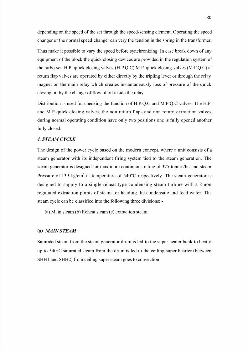
8/9/2019 Guru Nanak Dev Thermal Power
http://slidepdf.com/reader/full/guru-nanak-dev-thermal-power 80/120
dependin on the speed of the set throuh the speed-sensin element. @peratin the speed
chaner or the normal speed chaner can ver# the tension in the sprin in the transformer.
Thus make it possible to var# the speed before s#nchroni%in. >n case break down of an#
equipment of the block the quick closin devices are provided in the reulation s#stem of the turbo set. E.P. quick closin valves /E.P.K.? 8.P. quick closin valves /8.P.K.? at
return flap valves are operated b# either directl# b# the triplin lever or throuh the rela#
manet on the main rela# which creates instantaneousl# loss of pressure of the quick
closin oil b# the chane of flow of oil inside the rela#.
Distribution is used for checkin the function of E.P.K.? and 8.P.K.? valves. The E.P.
and 8.P quick closin valves$ the non return flaps and non return e4traction valves
durin normal operatin condition have onl# two positions one is full# opened another
full# closed.
8. STEAM CYCLE
The desin of the power c#cle based on the modern concept$ where a unit consists of a
steam enerator with its independent firin s#stem tied to the steam eneration. The
steam enerator is desined for ma4imum continuous ratin of =9(-tonnes!hr. and steam
Pressure of '=-k!cm) at temperature of (&0°? respectivel#. The steam enerator is
desined to suppl# to a sinle reheat t#pe condensin steam turbine with a : non
reulated e4traction points of steam for headin the condensate and feed water. The
steam c#cle can be classified into the followin three divisions, -
/a 8ain steam /b ;eheat steam /c e4traction steam
/! 5 MAIN STEAM
1aturated steam from the steam enerator drum is led to the super heater bank to heat if
up to (&0°? saturated steam from the drum is led to the ceilin super hearter /between
1EE' and 1EE) from ceilin super steam oes to convection
:0
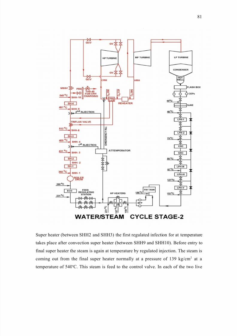
8/9/2019 Guru Nanak Dev Thermal Power
http://slidepdf.com/reader/full/guru-nanak-dev-thermal-power 81/120
1uper heater /between 1EE) and 1EE= the first reulated infection for at temperature
takes place after convection super heater /between 1EE and 1EE'0. *efore entr# to
final super heater the steam is aain at temperature b# reulated in5ection. The steam is
comin out from the final super heater normall# at a pressure of '= k!cm ) at a
temperature of (&0o?. This steam is feed to the control valve. >n each of the two live
:'
8/9/2019 Guru Nanak Dev Thermal Power
http://slidepdf.com/reader/full/guru-nanak-dev-thermal-power 82/120
steam lines there is one turbine side main steam stop valve and one hih pressure quick
closin valve alon with two control valves.
/70 EXTRACTION STEAM
1team for heatin of the condenser and the feed steam is e4tracted from : non reulated
e4traction points from the turbine. Eeatin is carried out in five staes of A.P. heaters$
one deareatin heater and in two E.P. heaters e4traction '$ )$ =$ is taken from A.P. turbine.
F4traction &$ ($ 6 and 9 are taken from 8.P. turbine. F4traction : is obtained from ?.;.E.
line first and second stae of heatin is done b# two sets of twin low-pressure heaters
mounted directl# in the A.P. casin of the turbine. F4traction =$ & and ( are connected to
the deaereatin heater placed above feed water storae tank 9 th and :th e4traction steam is
fed to the vertical E.P. heaters respectivel#.
/C0 RE*EAT STEAM
F4it steam from the E.P. turbine is taken back to the reheater section of the steam
eneratin unit. ;eheatin is done in two staes both b# flue as and b# super heated
steam. The steam to be reheated is first pass throuh the triple-heated e4chaner$ where
super heated steam is used as the heatin media. The steam is finall# reheated in final
reheaters /;EE= ;EE& and ;EE( suspended in the hori%ontal pass of the furnace.
;eheat steam at a normal pressure of =6.& k!cm) at a temperature of (&0 °? respectivel#
is fed to the 8.P. c#linder b# two hot reheat steam pipes throuh strainers and combined
stop and interceptor valves. >n each of the cold reheat steam lines from E.P. c#linder a
non-return valve is operated b# oil pressure is provided.
'. T8$7+ A55o$+ !; A8>+"+!$+
>. 1urface condenser.
>>. 1team 5et air e5ector
>>>. AP and EP heaters.
>. ?himne# steam condenser.
. Gland steam condenser.
>. @il purifier or centrifue.
>>. ?lean oil pump with clean oil tank
:)
8/9/2019 Guru Nanak Dev Thermal Power
http://slidepdf.com/reader/full/guru-nanak-dev-thermal-power 83/120
>>>. Dirt# oil pump with clean oil tank.
>. 2u4iliar# oil pump with au4iliar# oil tank
. 1tartin oil pump.
>. Fmerenc# oil pump.
/I0 SURFACE CONDENSER
Two surface condensers are used for condensin the steam which has worked in the
turbine. The coolant for condensin the steam is circulatin water which is inside the
condenser brass tubes and steam is outside.
T5#+5!" ;!! o? Co;$
• ?oolin 2rea ==00 msq.
• Number of brass tubes 6000
• ?irculatin water required 9(00 tonnes!hr.
• acuum in the condenser 0.0 k!cm sq.
/II0 STEAM JET AIR EJECTOR
1tartin e5ector is used for quick evacuation of the turbo set durin startin whereas main
steam 5et air e5ector is used to maintain acuum in the condenser. >t works on the
principle of FNT3;>C with steam workin media to e5ect air from the condenser.
/III0 LP AND *P *EATERS
>n reenerative s#stem there is a steam of ( AP heaters$ one Deaereator$ ) EP heaters. 2ll
AP and EP heaters are of surface t#pe i.e. condensate or feed water is inside the heater
tubes in the heater shells. A.P. heaters are of sinle flow whereas EP heaters are of double
flow t#pe. Deaereator is contact t#pe heater in which steam and condensate come in
direct contact.
/IV, V0 C*IMNEY STEAM AND GLAND STEAM CODENSER: - There are additional
two heatin staes provided in the reeneration s#stem of the turbine for heatin the
:=
8/9/2019 Guru Nanak Dev Thermal Power
http://slidepdf.com/reader/full/guru-nanak-dev-thermal-power 84/120
condense flowin throuh it steam leaks off from the turbine lands is used for heatin
the condensate in these heaters.
4VI? VII? VIII? IX? X5 VARIOUS OIL PUMPS
?entrifue is an oil purifier used to remove moisture and other impurities from the
turbine oil. 8a4imum allowable moisture content in the turbine oil is 0.)B. >n case the
oil level of the main oil tank is to be made up then either oil can transferred from clean
oil tank to main oil tank with centrifue or from dirt# oil tank to main oil tank with
centrifue.
4XI5 STARTING OIL PUMPS AND EMERGENCY OIL PUMPS
1tartin oil pumps suppl# the necessar# turbine oil durin startin of the turbine and upto
turbine speed of )=0 rpm till the main oil pump mounted on the turbine rotor at the EP
e4tension takes manuall# in order to provide lubrication oil for the turbo set. Fmerenc#
oil pumps are meant to start on auto$ when turbine trips and lubrication oil pressure falls
in order to provide lubrication to the turbine and enerator bearins.
MAIN TEC*NICAL DATA ABOUT TURBINE
a) T, Ba$! Para)tr$
• ;ated output measured at terminal of the enerator. ''0$000I"
• Fconomical output. ($000I"
• ;ated speed =$000 ;P8
• ;ated temp. @f steam 5ust before the stop valve. (=(°?
• 8a4 temp. @f steam before the stop valve (&(°?
• ;ated pressure of steam before the 8P casin ='.6= ata
• 8a4. Pressure of steam before the 8P casin =( ata
• ;ated temp. @f steam before the 8P casin (=(°?
• 8a4. Temp. of steam before the 8P casin (&(°?
:&
8/9/2019 Guru Nanak Dev Thermal Power
http://slidepdf.com/reader/full/guru-nanak-dev-thermal-power 85/120
4a5 S1$t) %& t"r=':
Governin valves ) interceptor valves
EP c#linder ) ;ow ?urtis wheel Q: movin wheels.
"t. of EP rotor is appro4. ($(000k.
8P c#linder ') movin wheels.
"t. @f 8P rotor is appro4. ''$000k
AP c#linder & 8ovin wheels of double flow desin.
"t. of 8P rotor is appro4. )&$000.
Direction of the turbine rotation is to the riht when lookin at the turbine from the front
bearin pedestal.
RELAY SECTION
Protective rela# is a device that detects the fault and initiates the operation of the circuit
breaker to isolate the defective section from the rest of the s#stem.
"e have seen that whenever fault occurs on the power s#stem$ the rela# detects the fault
and closes the trip coil circuit. This results in the openin of circuit breaker$ which
disconnects the fault# section. Thus a rela# ensures the safet# of the circuit equipments
from damae which ma# be causes b# the fault# current.
ESSENTIAL ELEMENTS OF A RELAY
2ll the rela#s have the followin three essential fundamental elements as shown in block
diaram see fi.
/a S+% ":- 1ensin or measurin element is the element which responds to
the chane in manitude or phase of the actuatin quantit# e.. current in the over current
rela#.
:(
8/9/2019 Guru Nanak Dev Thermal Power
http://slidepdf.com/reader/full/guru-nanak-dev-thermal-power 86/120
8/9/2019 Guru Nanak Dev Thermal Power
http://slidepdf.com/reader/full/guru-nanak-dev-thermal-power 87/120
/IV0 D+$5+o!" o$ $@$ 6o*$ $"!9- These rela#s operate when the applied
voltae and current assumes a specified phase. Displacement and no compensation is
allowed for fall in voltae.
/V0 D+!5 $"!9- The operation of these rela#s depends upon the ratio of the voltaeto the current.
/V+0 D+??$+!" $"!9- The operation of these rela#s takes place at some specific
phase difference or manitude difference between two or more electrical quantities.
=. A!!%r(' t% t, t) %& %/rat%':-
/i I!!o8 $"!9->n these rela#s$ complete operation takes place
instantaneousl# i.e.$ the operation is complete in a neliibl# small interval of time from
the incidence of the actuatin quantit#.
/ii D?++ +: "!% R"!9- >n these rela#s operation takes place after definite
time la which is independent of the manitude of actuatin quantit#.
/iii I@$ +: "!% R"!9- >n these rela#s the time of operation is inversel#
proportional to the manitude of actuatin quantit#.
I@$ D?++ M++:8: T+: L!% R"!9- >n these rela#s$ the time of operation is
appro4imatel# inversel# proportional to the actuatin quantit#$ but is never less than a
definite minimum time for which rela# is set.
T*ERMAL RELAYS
2 rela# in which heatin effect of electric current is used for its operation is known as
thermal rela#s. These rela#s ma# be actuated b# a.c. or d.c.
CONSTRUCTION
:9
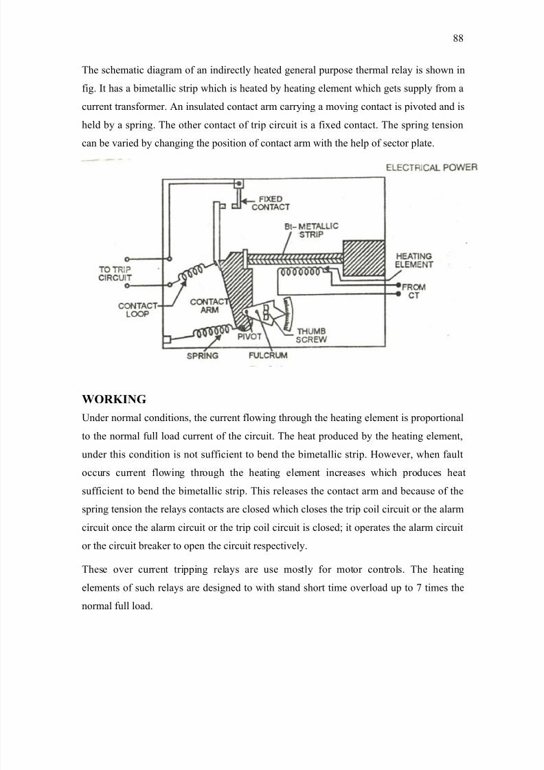
8/9/2019 Guru Nanak Dev Thermal Power
http://slidepdf.com/reader/full/guru-nanak-dev-thermal-power 88/120
The schematic diaram of an indirectl# heated eneral purpose thermal rela# is shown in
fi. >t has a bimetallic strip which is heated b# heatin element which ets suppl# from a
current transformer. 2n insulated contact arm carr#in a movin contact is pivoted and is
held b# a sprin. The other contact of trip circuit is a fi4ed contact. The sprin tension
can be varied b# chanin the position of contact arm with the help of sector plate.
WORKING3nder normal conditions$ the current flowin throuh the heatin element is proportional
to the normal full load current of the circuit. The heat produced b# the heatin element$
under this condition is not sufficient to bend the bimetallic strip. Eowever$ when fault
occurs current flowin throuh the heatin element increases which produces heat
sufficient to bend the bimetallic strip. This releases the contact arm and because of the
sprin tension the rela#s contacts are closed which closes the trip coil circuit or the alarm
circuit once the alarm circuit or the trip coil circuit is closed+ it operates the alarm circuit
or the circuit breaker to open the circuit respectivel#.
These over current trippin rela#s are use mostl# for motor controls. The heatin
elements of such rela#s are desined to with stand short time overload up to 9 times the
normal full load.
::
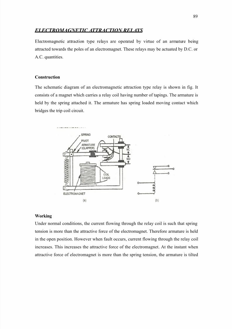
8/9/2019 Guru Nanak Dev Thermal Power
http://slidepdf.com/reader/full/guru-nanak-dev-thermal-power 89/120
ELECTROMAGNETIC ATTRACTION RELAYS
Flectromanetic attraction t#pe rela#s are operated b# virtue of an armature bein
attracted towards the poles of an electromanet. These rela#s ma# be actuated b# D.?. or
2.?. quantities.
Co$85+o
The schematic diaram of an electromanetic attraction t#pe rela# is shown in fi. >t
consists of a manet which carries a rela# coil havin number of tapins. The armature is
held b# the sprin attached it. The armature has sprin loaded movin contact which
brides the trip coil circuit.
Wo$)+%
3nder normal conditions$ the current flowin throuh the rela# coil is such that sprin
tension is more than the attractive force of the electromanet. Therefore armature is held
in the open position. Eowever when fault occurs$ current flowin throuh the rela# coil
increases. This increases the attractive force of the electromanet. 2t the instant when
attractive force of electromanet is more than the sprin tension$ the armature is tilted
:
8/9/2019 Guru Nanak Dev Thermal Power
http://slidepdf.com/reader/full/guru-nanak-dev-thermal-power 90/120
down wards and movin contact brides the fi4ed contacts. This closes the trip coil
circuit.
The current settin can be ad5usted b# chanin the number of turn of rela# coil. The
larer numbers of turns are introduced in the operatin coil$ the smaller is the value of actuatin current. The time settin can ad5ust b# chanin the tension of sprin b# a
screw. Terminal 2? act as normall# can also be used for the operation of another circuit.
INDUCTION RELAYS
The basic principle of operation of these rela#s is electromanetic induction. These rela#s
are onl# actuated b# a.c. 2n induction rela# essentiall# consists of a pivoted aluminumdisc place in between two alternatin fields of the same frequenc# but displaced from
each other b# some anle. 2 torque is produced in the disc b# the interaction of two
fields. 1uch rela#s ma# be over current reverse power or directional over current rela#s as
discussed in the comin articles.
INDUCTION TYPE OVER CURENT RELAY
Co$85+o
2n induction t#pe over current rela# is shown in fi. ( /a it consists of an aluminum disc
which is free to rotate to be placed in between the two electromanets. The upper manet
has three limbs whereas lower manet has two. The tapped windin is wound on the
central limbs of the upper manet. This windin is connected to the ?T of the line to be
protected. The tapins one connected to a plu settin bride as shown in fi.( /a b#
chanin the position of plu b# which the number of active turns of the primar# windin
can be varried$ thereb# the desired current settin is obtained. The secondar# is a closed
windin and wound on the central limb of the upper manet and both the limbs of the
lower manet. The windin is eneri%ed b# the primar# windin.
The controllin torque is provided b# connected a spiral sprin on the spindle of the disc.
The spindle of the disc also carries a movin contact$ when the disc rotated throuh a
preset anle$ the movin contact brides the two fi4ed contact of the trip coil circuit as
0
8/9/2019 Guru Nanak Dev Thermal Power
http://slidepdf.com/reader/full/guru-nanak-dev-thermal-power 91/120
shown in fi.( /b. The preset anle can be ad5usted to an# value between @ ° and =60°$
b# ad5ustin the anle$ the travel of the movin contact can be ad5usted and the rela# can
be set for an# desired time settin.
Wo$)+%
"hen current flows throuh the primar# windin$ an e.m.f. is induced in the secondar#
windin b# induction. 1ince secondar# is closed$ a current flows throuh it. The flu4es
are produced b# the currents flows throuh primar# and secondar# windin. These flu4es
are separated in phase and space and produces a drivin torque on the disc. This torque is
opposed b# the restrainin torque provided b# the sprin. 3nder normal conditions$ the
restrainin torque is more than the drivin torque$ therefore$ the disc remains stationar#.
Eowever when a fault occurs$ the current flowin throuh the primar# e4ceeds the preset
value. The drivin torque becomes more than the restrainin torque consequentl# the disc
rotates and movin contact brides the fi4ed contacts when the disc rotates throuh a pre-
set anle.
S65+?+5!+o o? o@$ 58$$ $"!9
1.No. 8))()=
8odel N@. ?DG ='FG ')') 2(
T#pe 2u4iliar# voltae ))0 d.c.
8anufacturer 7#oti Atd. *aroda.
'

8/9/2019 Guru Nanak Dev Thermal Power
http://slidepdf.com/reader/full/guru-nanak-dev-thermal-power 92/120
)
8/9/2019 Guru Nanak Dev Thermal Power
http://slidepdf.com/reader/full/guru-nanak-dev-thermal-power 93/120
WATER TREATMENT PLANT
The basic requirement of "ater Treatment in the thermal power station is to provide
suitable water for the boiler i.e. the water$ which is free from dissolved$ suspended$ and
an# other t#pe of impurities. >f the water is taken as such without an# treatment then this
will result in scale and slude formation$ caustic embrittlement and corrosion in the boiler
and the pipes. "ater Treatment at GNDTP$ *hatinda ma# be broadl# divided into
2 F4ternal "ater Treatment.
* >nternal "ater Treatment.
A. E>$!" W!$ T$!: 5o:6$+ o?-
a ?hlorination.
b 1edimentation < ?larification.
c ilteration.
d Deminerali%ation.
C*LORINATION:
*acteria and other livin oranisms results in the formation of alae on the surface of
tanks$ pipes and other equipments. 2ddition of o4idi%in aents such as chlorine <
bleachin powder destro# the bacteria or an# other micro oranisms. 2t present$ chlorine
dosin is done at >ntake. Pump Eouse and at both ?" Pump Eouse with Gas ?hlorinator
of vacuum t#pe at the rate of '0 I!Er.
=
8/9/2019 Guru Nanak Dev Thermal Power
http://slidepdf.com/reader/full/guru-nanak-dev-thermal-power 94/120
SEDIMENTATION @ CLARIFICATION:
The suspended impurities in water are removed b# sedimentation and clarification. "hen
the river or cannel water is allowed to stand for sometime in a bi tank or reservoir most
of the suspended material settles down. The process of clarification is done in clarifier
and is accelerated b# addin coaulant such as alum /aluminium and ferrous sulphate or
1odium 2luminate. These results in the formation of precipitate of aluminium h#dro4ide$
which tends to alomerate colloidal$@ranic and suspended impurities in water. The
precipitates so formed settles at the bottom of clarifier. These are removed b# operatin
desludin valve.
2l)/1@&= Q =?a/E?@=) =?a1@& Q )2l/@E= Q?@).
>mpurities not removed in this process are removed b# filteration. 2t present$ we have &
clarifiers with a clarif#in capacit# of ')00 8T!Er each to reduce turbidit# upto )0ppm.
FILTERATION:
>t is the process of passin of liquid containin suspended matter throuh a suitable
porous material /ilterin 8edium to effectivel# remove the suspended matter in the
liquid. or the process of filtration there are = pressure filters in each D.8.Plant havin a
capacit# of )9 8=!Er each. Turbidit# of filtered water from pressure filters is not reater
than ) ppm.
ilter media commonl# emplo#ed are raded and washed sand of effective si%e of 0.=(
mm to 0.( mm restin on supportin underbed of crushed ravel and pebbles of four
var#in si%e with coarsest si%e at the bottom of the bed.
DEMINERALI>ATION: 4REMOVAL OF DISSOLVED IMPURITIES5
The development of modern hih-pressure boilers has been accompanied b# serious
problems connected with the formation of scale$ corrosion etc.
The principle scale formin and hardness producin substances found in natural water are
the soluble salts of calcium and manesium. The most common are bi-carbonates
&
8/9/2019 Guru Nanak Dev Thermal Power
http://slidepdf.com/reader/full/guru-nanak-dev-thermal-power 95/120
?a/E?@=)$ 8/E?@=).The sulphate ?a1@&$81@&. The chlorides ?a?l)$ 8!?l) and
sometimes nitrates are also present. The processes which are used for water softenin are,
'. *oilin /or removin temporar# hardness onl#.
). Aime 1oda Treatment.=. *ase F4chaner Reolite process.
&. >on F4chane.
ION EXC*ANGE:
The deminerali%ation of water at GNDTP$ *2TE>ND2 is done b# ion e4chane process.
There are two D.8. Plants each havin capacit# 00 8T!da# desin for (B station make
up. The ion e4chane process is used in removin all the above scale formin
constituents. This is the most modern and latest method. The ion e4chane is the process
in which there is irreversible interchanes of ions of like sin between a solution and an
insoluble solid. >n this process the cations in water are e4chaned with E Q ions of cations
resins and anions are e4chaned with @Eions of anion resins.
RESIN:
;esin consists of a iant oranic molecule arraned in the form of porus framework$
havin replaceable EQ
ions attached to it in case of cations resin and replaceable @E-
ions
in case of anion resins.
The deminerali%ation process consists of = units in series$ one is called M?ation F4chane
3nitL and the other is called M2nion F4chane 3nitL. 8i4ed bed unit follows this.
9. C!+o E>5#!% U+-
This e4chaner removes all the cations such as 1odium /NaQ$ Potassium /I Q$
?alcium/?aQQ$ 8anesium/8QQetc. "hen the water passes throuh cations resin the
functional h#droen ion are replaced b# the cations with the formation of respective acid.
The equation is represented as,
/a ; 'EQ Q ?a/E?@=) → ; '?aQ Q E)?@=
/b ; 'EQ Q ?a1@& → ; '?aQ Q E)1@&
(
8/9/2019 Guru Nanak Dev Thermal Power
http://slidepdf.com/reader/full/guru-nanak-dev-thermal-power 96/120
8/9/2019 Guru Nanak Dev Thermal Power
http://slidepdf.com/reader/full/guru-nanak-dev-thermal-power 97/120
8i4ed bed contains both the cations and anion resins. 2n# cation or anion which has
slipped from the cation e4chaner and anion e4chaner are removed here in the mi4 bed
unit. 2fter mi4es bed treated water is quit suitable for use in boiler.
PE O 6.: to 9.)
?onductivit# O '.0 micromhos!cm
1i@) O U 0.0) ppm.
@thers O N>A
. I'tr'a# Watr Trat)'t:
"hen after standard treatment it is necessar# to further condition the boiler feed water
because D.8. "ater dissolves ?@) and@) in the storae tanks and becomes slihtl#
acidic and corrosive in character. This is treatment at various staes of feed water is
called internal water treatment. >nternal "ater Treatment is required b# chemical dosin
to combat the followin,
/a ?orrosion.
/b 1calin
/c Pittin
/d oamin
/e ?austic Fmbrittlement.
/f
/!0 Co$$o+o-
?orrosion is the radual destruction of metal b# chemical or electro chemical reaction of
metal with the surroundin medium. ?orrosion beins at the surface and raduall#
penetrates into the metal. >t also chanes the mechanical and ph#sical properties of
material.
/70 S5!"+%-
9
8/9/2019 Guru Nanak Dev Thermal Power
http://slidepdf.com/reader/full/guru-nanak-dev-thermal-power 98/120
@nce in boiler the water is heated to saturation. The temperature thus evaporates at the
point of contact with heated tube surface. The impurities are left in boiler water whose
concentration thereb# increases. The impurities to deposit on the tube surface a scale.
1calin ma# take place in boiler drum$ water walls heater and feed water pipin. >t
reduces the flow requirin an increase in pressure to maintain water deliver# and more
fuel consumption. Then this condition occurs tube failure due to overheatin$ blisterin
and rupturin ma# be e4pected.
/50 P++%-
"hen minute holes are created on metal surface b# o4idation it is know as pittin. This
t#pe of corrosion is caused b# dissolved o4#en in water. The residual o4#en is removed
b# treatment with h#dra%ine.
/;0 Fo!:+%-
oamin primin and carr# over are closel# associated terms production of stable foam
over the surface of water is called foamin. Too hih concentration of dissolved salts is
the cause of foamin.
/0 C!8+5 E:7$+":-
The tendenc# of caustic /1odium E#dro4ide to concentrate in drum seals$ under rivets or
at rolled tube 5oints in5urin the metal is called caustic embrittlement. oamin$ primin$
carr#over$ caustic embrittlement can be controlled b# maintain proper alkalinit#$
operatin blow down and maintainin proper drum level i.e. =0 to J 60 mm.
C*EMICAL DO>ING FOR INTERNAL TREATMENT OF WATER
To take care of scalin and corrosion followin chemical dosin is done to neutrali%e
effect of ?@)$ @) ?alcium 8anesium$ 1alts and silica etc.
/' 8orrholine do%in.
/) E#dra%ine do%in.
/= Phosphate do%in.
:
8/9/2019 Guru Nanak Dev Thermal Power
http://slidepdf.com/reader/full/guru-nanak-dev-thermal-power 99/120
/10 Mo$$#o"+ ;o+%-
This do%in is done to increase the pE of the feed water and remove an# in the s#stem
)?&E@N Q )?@) → )?&E?@= Q N)
The pE of the feed and steam c#cle is maintained between :.& to :.: to minimi%e
corrosion$ it is do%ed at the dischare of condensate e4traction pump.
/20 H9;$!+ ;o+%-
>t is a powerful reducin aent which reacts with dissolved o4#en under boiler water
condition to produce water and nitroen onl# as follows.
N)E& Q @) → )E)@) Q N)
E#dra%ine also reduces non-protective iron o4ide to protective manetite.
/30 P#o6#! ;o+%-
>t is done with two aims,
'. 2n# hardness /salts of ?a and 8 enterin the boiler is likel# to form scale in
boiler. The addition of phosphate prevents this. The phosphate reacts with
calcium and manesium to form slude$ which can be removed b# blow
down. >n this wa#$ ?a and 8 scales are completel# removed from the boiler
drum.
). T.1.P. maintains proper pE of the boiler water. T.1.P. on h#drol#sis with boiler
water liberates Na@E with the reaction.
Na=P@& Q E)@ → Na)EP@& Q Na@E

8/9/2019 Guru Nanak Dev Thermal Power
http://slidepdf.com/reader/full/guru-nanak-dev-thermal-power 100/120
'00
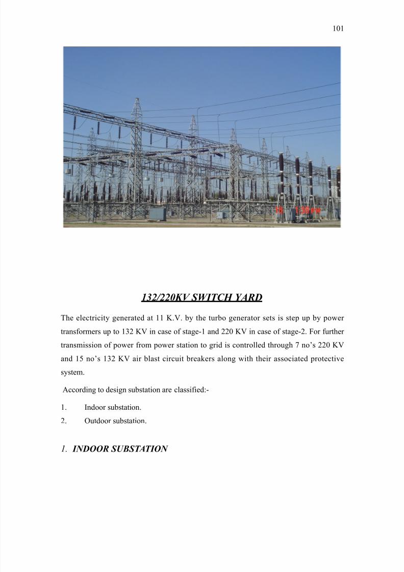
8/9/2019 Guru Nanak Dev Thermal Power
http://slidepdf.com/reader/full/guru-nanak-dev-thermal-power 101/120
97KV SWITC* YARD
The electricit# enerated at '' I.. b# the turbo enerator sets is step up b# power
transformers up to '=) I in case of stae-' and ))0 I in case of stae-). or further
transmission of power from power station to rid is controlled throuh 9 noCs ))0 I
and '( noCs '=) I air blast circuit breakers alon with their associated protective
s#stem.
2ccordin to desin substation are classified,-
'. >ndoor substation.
). @utdoor substation.
1. INDOOR SUBSTATION
'0'
8/9/2019 Guru Nanak Dev Thermal Power
http://slidepdf.com/reader/full/guru-nanak-dev-thermal-power 102/120
>n these substations the equipments are installed within the buildin of the substation and
hence the name indoor substation. 1uch substations are usuall# desined for '' I but
can be erected for == I or 66 I$ if the surroundin atmosphere is containin
impurities$ which ma# damae the equipments.
2. OUTDOOR SUBSTATION
>n these substations$ the equipments are installed open and hence the name outdoor
substation. 1uch substation can be desined to handle low$ hih and e4tra hih voltaes.
The outdoor substations ma# be further classified as,
/> Pole mounted substation
/>> oundation mounted substation
(I) POLE MOUNTED SUBSTATION
1uch substations are desined for monthl# distribution transformers of capacit# unto =00
I2. 1uch substations are cheapest simple and smallest of other substations. 2ll the
equipmentCs are of outdoor t#pe and mounted on the supportin structure of ET
distribution line. Tripple pole mechanicall# operated switch is used for switchin on and
off of E.T transmission line. To control A.T. side$ iron clad low-tension switch of suitable
capacit# with fuses is installed. Aihtin arrestors are installed over the ET line to protect
the installation from the sures. 1ubstations are earthed at two or more places. Generall#
transformers of capacit# upto ')( I2 are mounted on double pole structure and for
transformers of capacit# above ')( I2 & pole structure with suitable platform is used
such substations are situated in ver# thickl# populated location.
'0)
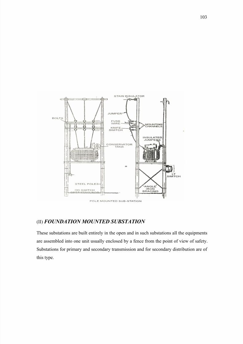
8/9/2019 Guru Nanak Dev Thermal Power
http://slidepdf.com/reader/full/guru-nanak-dev-thermal-power 103/120
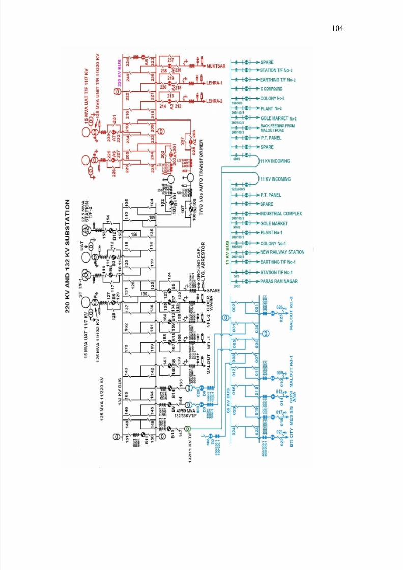
8/9/2019 Guru Nanak Dev Thermal Power
http://slidepdf.com/reader/full/guru-nanak-dev-thermal-power 104/120
'0&
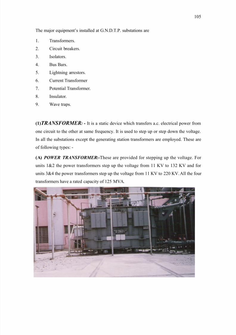
8/9/2019 Guru Nanak Dev Thermal Power
http://slidepdf.com/reader/full/guru-nanak-dev-thermal-power 105/120
The ma5or equipmentCs installed at G.N.D.T.P. substations are
'. Transformers.
). ?ircuit breakers.
=. >solators.&. *us *ars.
(. Aihtnin arrestors.
6. ?urrent Transformer
9. Potential Transformer.
:. >nsulator.
. "ave traps.
/10TRANSFORMER: >t is a static device which transfers a.c. electrical power from
one circuit to the other at same frequenc#. >t is used to step up or step down the voltae.
>n all the substations e4cept the eneratin station transformers are emplo#ed. These are
of followin t#pes, -
/A0 POWER TRANSFORMER-These are provided for steppin up the voltae. or
units '<) the power transformers step up the voltae from '' I to '=) I and for
units =<& the power transformers step up the voltae from '' I to ))0 I. 2ll the four
transformers have a rated capacit# of ')( 82.
'0(
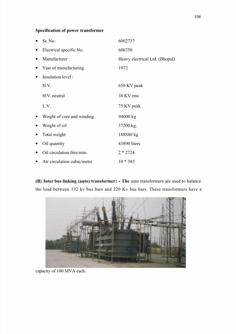
8/9/2019 Guru Nanak Dev Thermal Power
http://slidepdf.com/reader/full/guru-nanak-dev-thermal-power 106/120
S65+?+5!+o o? 6o*$ $!?o$:$
• 1r. No. 600)9=9
• Flectrical specific No. 600)(0
• 8anufacturer Eeav# electrical Atd. /*hopal
• ear of manufacturin '9)
• >nsulation level ,
E.. 6(0 I peak
E.. neutral =: I rms
A.. 9( I peak
• "eiht of core and windin &000 k
• "eiht of oil =9)00 k.
• Total weiht '::::0 k
• @il quantit# &=:0 liters
• @il circulation litre!min. ) V )9)&
• 2ir circulation cubic!metre '0 V =:(
/B0 I$ 78 "+)+% /!8o0 $!?o$:$- T# auto transformers are used to balance
the load between '=) kv bus bars and ))0 Iv bus bars. These transformers have a
capacit# of '00 82 each.
'06
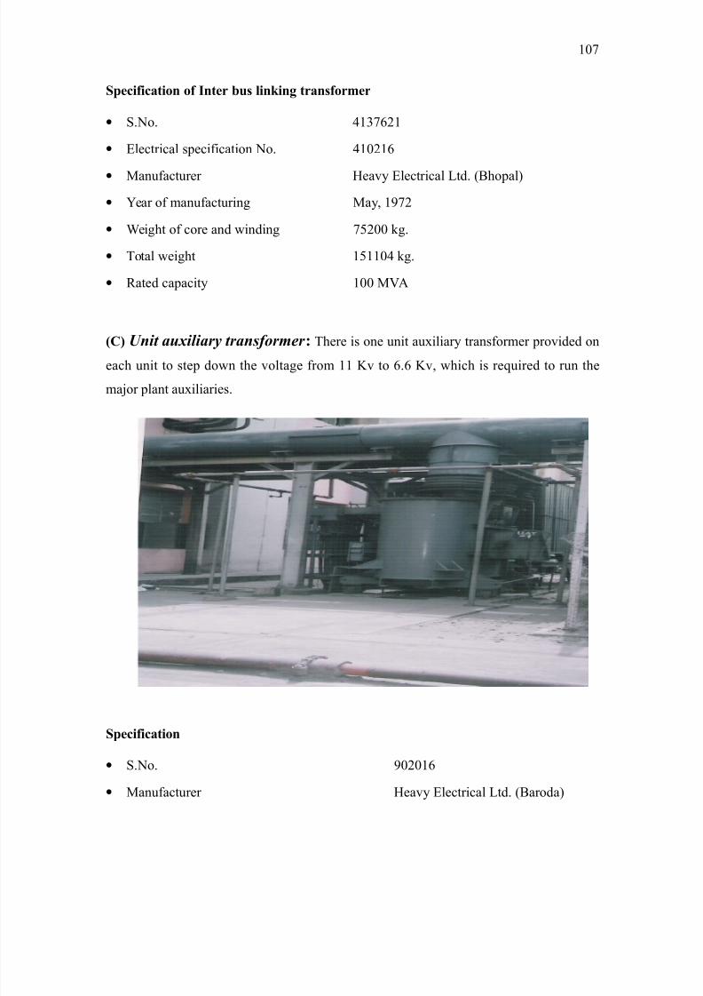
8/9/2019 Guru Nanak Dev Thermal Power
http://slidepdf.com/reader/full/guru-nanak-dev-thermal-power 107/120
S65+?+5!+o o? I$ 78 "+)+% $!?o$:$
• 1.No. &'=96)'
• Flectrical specification No. &'0)'6
• 8anufacturer Eeav# Flectrical Atd. /*hopal
• ear of manufacturin 8a#$ '9)
• "eiht of core and windin 9()00 k.
• Total weiht '(''0& k.
• ;ated capacit# '00 82
/C0U't a";#ar1 tra'$&%r)r -
There is one unit au4iliar# transformer provided on
each unit to step down the voltae from '' Iv to 6.6 Iv$ which is required to run the
ma5or plant au4iliaries.
S65+?+5!+o
• 1.No. 0)0'6
• 8anufacturer Eeav# Flectrical Atd. /*aroda
'09
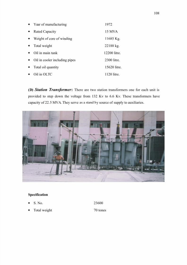
8/9/2019 Guru Nanak Dev Thermal Power
http://slidepdf.com/reader/full/guru-nanak-dev-thermal-power 108/120
• ear of manufacturin '9)
• ;ated ?apacit# '( 82
• "eiht of core of windin ''6:( I.
• Total weiht ))':: k.
• @il in main tank '))00 litre.
• @il in cooler includin pipes )=00 litre.
• Total oil quantit# '(6)0 litre.
• @il in @AT? '')0 litre.
/D0 Stat%' Tra'$&%r)r - There are two station transformers one for each unit is
provided to step down the voltae from '=) Iv to 6.6 Iv. These transformers have
capacit# of )).( 82. The# serve as a stand b# source of suppl# to au4iliaries.
S65+?+5!+o
• 1. No. )=600
• Total weiht 90 tones
'0:
8/9/2019 Guru Nanak Dev Thermal Power
http://slidepdf.com/reader/full/guru-nanak-dev-thermal-power 109/120
• 8anufacturer 8ade in *omba# 8artin *urn Atd.
• ear of manufacturin '9)
• @il in main tank '&&0 lt.
• @il in cooler includin pipe work &(00 lt.
• @il in @AT? '960 lt.
• Total oil )')00 lt.
45CIRCUIT BREAKER
?ircuit breaker is a device$ which ma# be operated under different conditions i.e. no load$
full load fault conditions. Eowever the ma5or dut# of a circuit breaker is to operate the
circuit breaker under fault conditions under short circuit conditions$ a circuit breaker
required to perform three ma5or duties,-
/i >t must be capable of openin the circuit under abnormal conditions.
/ii >t must be capable of classin the circuit on to a fault.
/iii >t must be capable of carr#in a fault current safel# for a short time while another
circuit breaker is clearin the fault.
OPERATING PRINCIPLE OF A CIRCUIT BREAKER
2 circuit breaker is a device which.
/i 8akes or breaks a circuit either manuall# or b# remote control under normal
conditions.
/ii *reaks a circuit automaticall# under abnormal conditions.
/iii 8akes a circuit manuall# or b# remote control under abnormal conditions.
Thus$ circuit breaker is 5ust a switch which can be opened under normal abnormal
conditions both manuall# and automaticall#.
To perform the above operations$ a circuit breaker essentiall# consists of fi4ed and
movin contacts$ called electrodes$ under normal operatin conditions+ these contacts
remain closed until and unless these are not operated manuall# or b# remote control.
'0
8/9/2019 Guru Nanak Dev Thermal Power
http://slidepdf.com/reader/full/guru-nanak-dev-thermal-power 110/120
8/9/2019 Guru Nanak Dev Thermal Power
http://slidepdf.com/reader/full/guru-nanak-dev-thermal-power 111/120
short circuit conditions depends upon its abilit# to with stand the effects of
electromanetic forces. These forces are proportional to the square of the peak value of
the current on closin.
The peak value of the current durin the first c#cle of current wave after the circuit thefirst c#cle of current wave after the circuit is closed b# the circuit breaker is called
makin capacit#. The makin capacit# is stated in terms of a peak value of current instead
of and r.m.s. value.
To find out the makin capacit# the s#mmetrical breakin current is multiplied b# √) to
convert the r.m.s value to peak value and then it is multiplied b# '.: to include the
doublin effect of ma4imum as#mmetr#. 8akin capacit# O √) V '.: V s#mmetrical
breakin capacit# O ).((V s#mmetrical breakin capacit#.
45S,%rt t) !a/a!t1 - 1ometimes fault occurs in the power s#stem in such a wa#
that one circuit breaker is clearin the fault at that time the other circuit breaker
connected in series must carr# the fault current safel# for a short period. 8oreover
sometimes the fault on the power s#stem is of ver# temporar# nature and presets for a
small period after which the fault is automaticall# cleared. >n the interest of continuit# of
suppl# the circuit breaker should not be allowed to trip in such situations and should be
capable of carr#in the fault current safel# for a short period.
The period for which the circuit breaker is able to carr# the fault current while remainin
closed is called short time capacit# of the circuit breaker.
2t G.N.D.T.P switch #ard !+$ 7"! 5+$58+ 7$!)$ and SF 5+$58+ 7$!)$ are
emplo#ed instead of oil ?ircuit breakers due to followin reasons,-
/i There is no risk of fire ha%ard and e4plosion.
/ii Due to less arc duration in it as compared to that in oil circuit breakers$ burnin of
contact is less.
/iii >t requires less maintenance
/iv The# provide facilit# of hih speed reclosure.
AXIAL-BLAST AIR CIRCUIT BREAKERS
'''
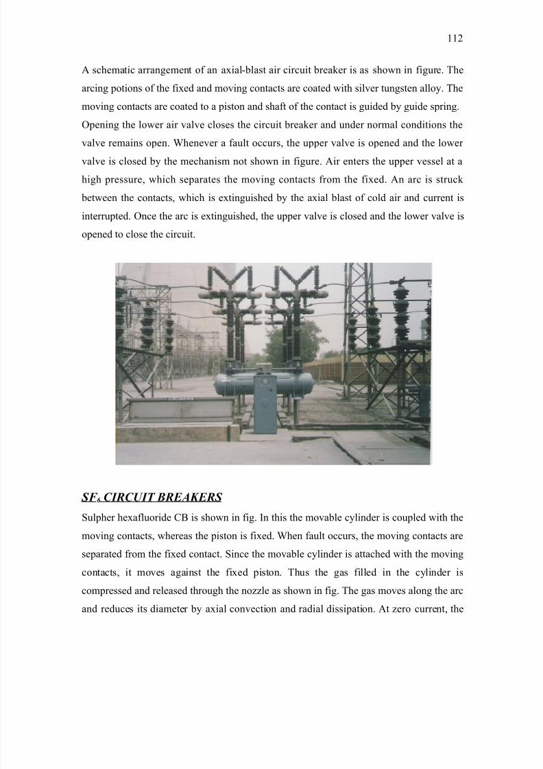
8/9/2019 Guru Nanak Dev Thermal Power
http://slidepdf.com/reader/full/guru-nanak-dev-thermal-power 112/120
2 schematic arranement of an a4ial-blast air circuit breaker is as shown in fiure. The
arcin potions of the fi4ed and movin contacts are coated with silver tunsten allo#. The
movin contacts are coated to a piston and shaft of the contact is uided b# uide sprin.
@penin the lower air valve closes the circuit breaker and under normal conditions the
valve remains open. "henever a fault occurs$ the upper valve is opened and the lower
valve is closed b# the mechanism not shown in fiure. 2ir enters the upper vessel at a
hih pressure$ which separates the movin contacts from the fi4ed. 2n arc is struck
between the contacts$ which is e4tinuished b# the a4ial blast of cold air and current is
interrupted. @nce the arc is e4tinuished$ the upper valve is closed and the lower valve is
opened to close the circuit.
SF 6 CIRCUIT BREAKERS
1ulpher he4afluoride ?* is shown in fi. >n this the movable c#linder is coupled with the
movin contacts$ whereas the piston is fi4ed. "hen fault occurs$ the movin contacts areseparated from the fi4ed contact. 1ince the movable c#linder is attached with the movin
contacts$ it moves aainst the fi4ed piston. Thus the as filled in the c#linder is
compressed and released throuh the no%%le as shown in fi. The as moves alon the arc
and reduces its diameter b# a4ial convection and radial dissipation. 2t %ero current$ the
'')
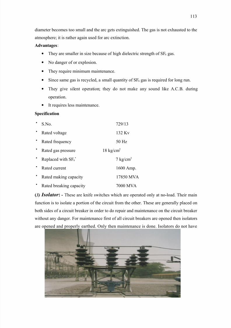
8/9/2019 Guru Nanak Dev Thermal Power
http://slidepdf.com/reader/full/guru-nanak-dev-thermal-power 113/120
diameter becomes too small and the arc ets e4tinuished. The as is not e4hausted to the
atmosphere+ it is rather aain used for arc e4tinction.
A;@!!%,
• The# are smaller in si%e because of hih dielectric strenth of 16 as.
• No daner of or e4plosion.
• The# require minimum maintenance.
• 1ince same as is rec#cled$ a small quantit# of 16 as is required for lon run.
• The# ive silent operation+ the# do not make an# sound like 2.?.*. durin
operation.
• >t requires less maintenance.
S65+?+5!+o
• 1.No. 9)!'=
• ;ated voltae '=) Iv
• ;ated frequenc# (0 E%
• ;ated as pressure ': k!cm)
• ;eplaced with 16V 9 k!cm)
• ;ated current '600 2mp.
• ;ated makin capacit# '9:(0 82
• ;ated breakin capacit# 9000 82
/5 I$%#at%r - These are knife switches which are operated onl# at no-load. Their main
function is to isolate a portion of the circuit from the other. These are enerall# placed on
both sides of a circuit breaker in order to do repair and maintenance on the circuit breaker
without an# daner. or maintenance first of all circuit breakers are opened then isolators
are opened and properl# earthed. @nl# then maintenance is done. >solators do not have
''=
8/9/2019 Guru Nanak Dev Thermal Power
http://slidepdf.com/reader/full/guru-nanak-dev-thermal-power 114/120
the arc control devices and therefore cannot be used to interrupt current at which an arc
will be drawn across the contacts. The open arc that would be drawn in such a case is
ver# danerous in that it will not onl# damae the isolator and the equipment surroundin
it$ but will also as a rule will cause flash over between phases. >n other words results in
short circuit in the installation. That is wh# isolators are used onl# for disconnectin and
connectin parts or units after first de-eneri%in them b# openin their circuits with
respective circuit breakers.
S65+?+5!+o
• 1.No. 0
• 8anufacturer Ei-elm industries Pvt. Atd.$ 8adras
•
3nit t#pe TEP• >solator (&'!=
• 2u4iliar# switch no. of pairs ')
• Pressure '6 k!cm)
• >solator k '=) k
• ?ontrol voltae ))0
• >solator current :00 2mp.
( 85 B"$ Bar$: The thick conductors run on the towers at the eneratin stations$ rid
stations or sub-stations operatin at constant voltae required to connect a number of
enerators or feeders operatin at the same voltae are called bus-bars.
The bus bars are arraned in different manner. The main aim of an# particular
arranement of bus bars is to achieve adequate operatin fle4ibilit#$ sufficient reliabilit#
and minimum cost. 2t G.N.D.T.P. there are two noCs '=) k *us bars are made up of aluminum. The bus coupler number two connects the '=) k bus bars and ))0 k bus
bars with each other.
/'0 L,t'' Arr$t%r : 2 lihtnin arrestor or sure diverter is a device which
provides an eas# conductin path or relativel# low impedance path for the flow of current
''&

8/9/2019 Guru Nanak Dev Thermal Power
http://slidepdf.com/reader/full/guru-nanak-dev-thermal-power 115/120
when the s#stem voltae increases more than the desined value and reains its oriinal
properties of an insulator at normal voltae.These are the arc apparatus devices desined
to protect insulators of power lines and electrical installation from lihtin sures b#
divertin the sure to earth and instantl# restorin the circuit insulation to its normal
strenth with respect to earth. These are connected between earth and line. Their purpose
is to protect the t!f windin aainst over voltaes.
N5+9 o? "+%#+% !$$o$
The round wires and earth screens do not provide protection aainst the hih voltae
waves reachin at the terminals of costl# equipment such as transformers. These hih
voltae waves ma# cause the followin damaes.
/i The waves ma# cause flash over in the internal windins of transformer and
spoils the windin insulation.
/ii >t ma# cause internal flash over between turns of the same windin of transformer.
/iii >t ma# cause e4ternal flash over between the terminals of electrical equipment$
which ma# cause damae to insulator.
/iv >t ma# cause internal or e4ternal flash over causin buildin up of the oscillations
in the electrical apparatus. Eence it is absolutel# necessar# to divert this hih
''(
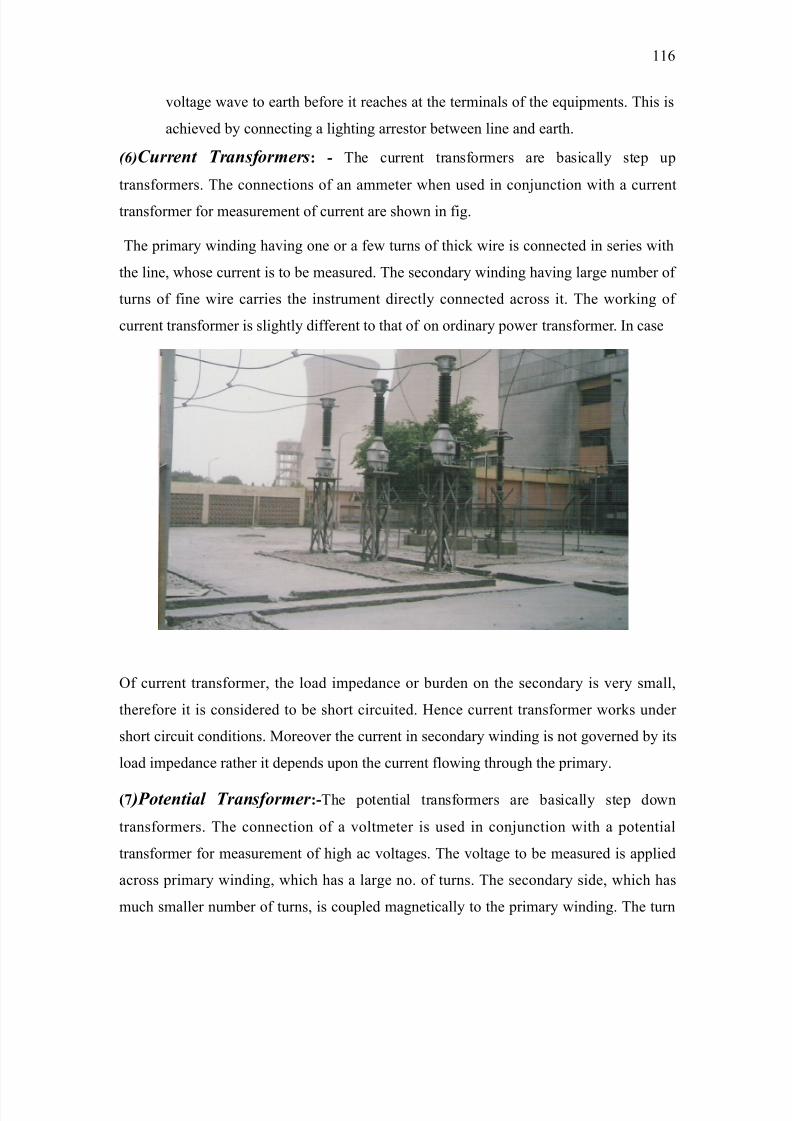
8/9/2019 Guru Nanak Dev Thermal Power
http://slidepdf.com/reader/full/guru-nanak-dev-thermal-power 116/120
voltae wave to earth before it reaches at the terminals of the equipments. This is
achieved b# connectin a lihtin arrestor between line and earth.
465C"rr't Tra'$&%r)r$- The current transformers are basicall# step up
transformers. The connections of an ammeter when used in con5unction with a current
transformer for measurement of current are shown in fi.
The primar# windin havin one or a few turns of thick wire is connected in series with
the line$ whose current is to be measured. The secondar# windin havin lare number of
turns of fine wire carries the instrument directl# connected across it. The workin of
current transformer is slihtl# different to that of on ordinar# power transformer. >n case
@f current transformer$ the load impedance or burden on the secondar# is ver# small$
therefore it is considered to be short circuited. Eence current transformer works under
short circuit conditions. 8oreover the current in secondar# windin is not overned b# its
load impedance rather it depends upon the current flowin throuh the primar#.
/ 5P%t'ta# Tra'$&%r)r -The potential transformers are basicall# step down
transformers. The connection of a voltmeter is used in con5unction with a potential
transformer for measurement of hih ac voltaes. The voltae to be measured is applied
across primar# windin$ which has a lare no. of turns. The secondar# side$ which has
much smaller number of turns$ is coupled maneticall# to the primar# windin. The turn
''6
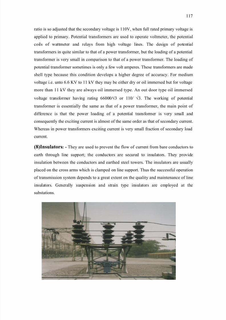
8/9/2019 Guru Nanak Dev Thermal Power
http://slidepdf.com/reader/full/guru-nanak-dev-thermal-power 117/120
ratio is so ad5usted that the secondar# voltae is ''0$ when full rated primar# voltae is
applied to primar#. Potential transformers are used to operate voltmeter$ the potential
coils of wattmeter and rela#s from hih voltae lines. The desin of potential
transformers in quite similar to that of a power transformer$ but the loadin of a potential
transformer is ver# small in comparison to that of a power transformer. The loadin of
potential transformer sometimes is onl# a few volt amperes. These transformers are made
shell t#pe because this condition develops a hiher deree of accurac#. or medium
voltae i.e. unto 6.6 I to '' k the# ma# be either dr# or oil immersed but for voltae
more than '' k the# are alwa#s oil immersed t#pe. 2n out door t#pe oil immersed
voltae transformer havin ratin 66000!√= or ''0! √=. The workin of potential
transformer is essentiall# the same as that of a power transformer$ the main point of
difference is that the power loadin of a potential transformer is ver# small and
consequentl# the e4citin current is almost of the same order as that of secondar# current.
"hereas in power transformers e4citin current is ver# small fraction of secondar# load
current.
/0I8"!o$- The# are used to prevent the flow of current from bare conductors to
earth throuh line support+ the conductors are secured to insulators. The# provide
insulation between the conductors and earthed steel towers. The insulators are usuall#
placed on the cross arms which is clamped on line support. Thus the successful operation
of transmission s#stem depends to a reat e4tent on the qualit# and maintenance of line
insulators. Generall# suspension and strain t#pe insulators are emplo#ed at the
substations.
''9
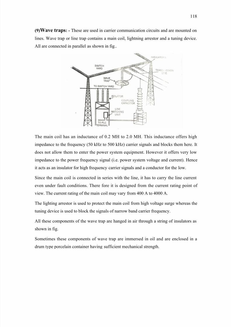
8/9/2019 Guru Nanak Dev Thermal Power
http://slidepdf.com/reader/full/guru-nanak-dev-thermal-power 118/120
/<0W!@ $!6- These are used in carrier communication circuits and are mounted on
lines. "ave trap or line trap contains a main coil$ lihtnin arrestor and a tunin device.
2ll are connected in parallel as shown in fi..
The main coil has an inductance of 0.) 8E to ).0 8E. This inductance offers hih
impedance to the frequenc# /(0 kE% to (00 kE% carrier sinals and blocks them here. >t
does not allow them to enter the power s#stem equipment. Eowever it offers ver# low
impedance to the power frequenc# sinal /i.e. power s#stem voltae and current. Eence
it acts as an insulator for hih frequenc# carrier sinals and a conductor for the low.
1ince the main coil is connected in series with the line$ it has to carr# the line current
even under fault conditions. There fore it is desined from the current ratin point of
view. The current ratin of the main coil ma# var# from &00 2 to &000 2.
The lihtin arrestor is used to protect the main coil from hih voltae sure whereas the
tunin device is used to block the sinals of narrow band carrier frequenc#.
2ll these components of the wave trap are haned in air throuh a strin of insulators as
shown in fi.
1ometimes these components of wave trap are immersed in oil and are enclosed in a
drum t#pe porcelain container havin sufficient mechanical strenth.
'':
8/9/2019 Guru Nanak Dev Thermal Power
http://slidepdf.com/reader/full/guru-nanak-dev-thermal-power 119/120
1pendin m# si4 months of trainin in Guru Nanak Dev Thermal Plant$ *athinda$ >
concluded that this is a ver# e4cellent industr# of its own t#pe. The# have achieved
milestones in the field of power eneration. The# uide well to ever# person in the
industr# i.e. trainees or an# worker. > had an opportunit# to work in various sections
namel# switch ear$ *oiler section$ Turbine section$ De-minerali%ed water plant$ F.1.P$
F8-) ?FAA etc. while attendin various equipments and machines. > had ot an
endeverous knowlede about the handlin of coal$ various processes involved like
unloadin$ beltin$ crushin and firin of coal. The other machines related to m# field
that > ot familiar with boiler$ turbine$ compressors$ condenser etc. > found that there
e4isted a bi ap between the workin in an institute workshop and that in the industr#.
2bove all the knowlede about the production of electricit# from steam helped me a lot
to discover and sort out m# problems in m# mind related to the steam turbine$ their
manufacture$ their capacit#$ their anle of blades and their manufacturin. The trainin
that > had underone in this industr# will definitel# help me to appl# theoretical
knowlede to the practical situation with confidence.
''
CONCLUSION
8/9/2019 Guru Nanak Dev Thermal Power
http://slidepdf.com/reader/full/guru-nanak-dev-thermal-power 120/120
'. 2 Te4tbook of electrical technolo# /2.? < D.? 8achines J B.L.THERAA, A.K.THERAA
). 2 course in electrical power, - .B.GUPTA
=. 2 course in electrical < electronic measurement and instrumentation, - A.K.SAWHNEY
&. 2 course in electrical power, - M.L.SONI, P.V.GUPTA
(. 2 te4tbook of power plant enineerin, - E$. R.K.RAPUT
6. www.wikipedia.com
9. www.sensorland.com
:. 8anual of GURU NANAK DEV THERMAL PLANT$ *2TE>ND2.
')0
BIBLIOGRAPHY