gx-series ethercat slave units user's manual
TRANSCRIPT

EtherCAT Remote I/O Terminal
GX-series
EtherCAT® Slave Units
Digital I/O UnitsAnalog I/O UnitsEncoder Input UnitsIO-Link Master Unit
User’s Manual
W488-E1-06
GX-IDGX-ODGX-OCGX-MDGX-ADGX-DAGX-ECGX-ILMXWT-IDXWT-OD
All rights reserved. No part of this publication may be reproduced, stored in a retrieval system, or transmitted, in any form, or by any means, mechanical, electronic, photocopying, recording, or otherwise, without the prior written permission of OMRON.
No patent liability is assumed with respect to the use of the information contained herein. Moreover, because OMRON is constantly striving to improve its high-quality products, the information contained in this manual is subject to change without notice. Every precaution has been taken in the preparation of this manual. Neverthe-less, OMRON assumes no responsibility for errors or omissions. Neither is any liability assumed for damages resulting from the use of the information contained in this publication.
• Sysmac and SYSMAC are trademarks or registered trademarks of OMRON Corporation in Japan and other countries for OMRON factory automation products.
• Microsoft, Windows, Windows Vista, Excel, and Visual Basic are either registered trademarks or trademarks of Microsoft Corporation in the United States and other countries.
• EtherCAT® is registered trademark and patented technology, licensed by Beckhoff Automation GmbH, Germany.
• Safety over EtherCAT® is registered trademark and patented technology, licensed by Beckhoff Automation GmbH, Germany.
• ODVA, CIP, CompoNet, DeviceNet, and EtherNet/IP are trademarks of ODVA.
• The SD and SDHC logos are trademarks of SD-3C, LLC.
Other company names and product names in this document are the trademarks or registered trademarks of their respective companies.
Trademarks
Copyrights
NOTE
Microsoft product screen shots reprinted with permission from Microsoft Corporation.

GX-seriesEtherCAT Slave UnitsUser’s ManualRevised October 2016

1GX-series EtherCAT Slave Unit User’s Manual
Introduction
Thank you for purchasing a GX-series EtherCAT Slave Unit.This manual contains information you need to know to use the EtherCAT Slave Unit.Before use, please make sure that you thoroughly read the manual and have a full understanding of the products functions and performance.After you finished reading this manual, please keep it in a convenient place.
This manual is intended for the following individuals.
Those having electrical knowledge (certified electricians or individuals having equivalent knowledge) and also being qualified for one of the following:• Introducing FA equipment• Designing FA systems• Managing FA sites
Intended Readers
2 GX-series EtherCAT Slave Unit User’s Manual
How to Read the Manual
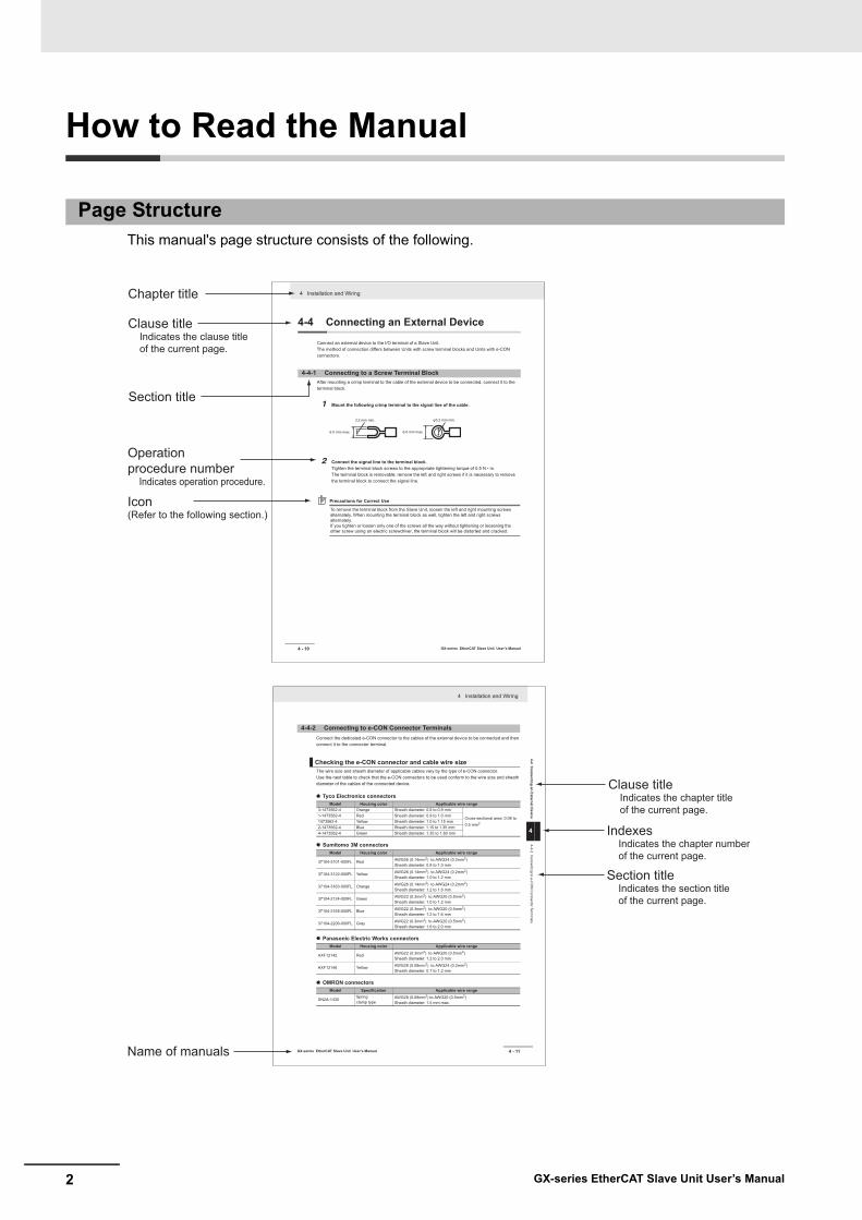
This manual's page structure consists of the following.
Page Structure
IndexesIndicates the chapter number of the current page.
Icon(Refer to the following section.)
Clause titleIndicates the clause title of the current page.
Operation procedure number
Indicates operation procedure.
Section title
Name of manuals
Clause titleIndicates the chapter title of the current page.
Section titleIndicates the section title of the current page.
Chapter title 4 Installation and Wiring
4 - 10 GX-series EtherCAT Slave Unit User’s Manual
4-4 Connecting an External Device
Connect an external device to the I/O terminal of a Slave Unit.The method of connection differs between Units with screw terminal blocks and Units with e-CON connectors.
After mounting a crimp terminal to the cable of the external device to be connected, connect it to the terminal block.
1 Mount the following crimp terminal to the signal line of the cable.
2 Connect the signal line to the terminal block.Tighten the terminal block screws to the appropriate tightening torque of 0.5 N • m.The terminal block is removable; remove the left and right screws if it is necessary to remove the terminal block to connect the signal line.
Precautions for Correct Use
To remove the terminal block from the Slave Unit, loosen the left and right mounting screws alternately. When mounting the terminal block as well, tighten the left and right screws alternately.If you tighten or loosen only one of the screws all the way without tightening or loosening the other screw using an electric screwdriver, the terminal block will be distorted and cracked.
4-4-1 Connecting to a Screw Terminal Block
6.0 mm max. 6.0 mm max.
φ3.2 mm min.3.2 mm min.
4 - 11
4 Installation and Wiring
GX-series EtherCAT Slave Unit User’s Manual
4-4 Connecting an External D
evice
4
4-4-2 Connecting to e-C
ON
Connector Term
inals
Connect the dedicated e-CON connector to the cables of the external device to be connected and then connect it to the connector terminal.
The wire size and sheath diameter of applicable cables vary by the type of e-CON connector.Use the next table to check that the e-CON connectors to be used conform to the wire size and sheath diameter of the cables of the connected device.
Tyco Electronics connectors
Sumitomo 3M connectors
Panasonic Electric Works connectors
OMRON connectors
4-4-2 Connecting to e-CON Connector Terminals
Checking the e-CON connector and cable wire size
Model Housing color Applicable wire range3-1473562-4 Orange Sheath diameter: 0.6 to 0.9 mm
Cross-sectional area: 0.08 to 0.5 mm2
1-1473562-4 Red Sheath diameter: 0.9 to 1.0 mm1473562-4 Yellow Sheath diameter: 1.0 to 1.15 mm2-1473562-4 Blue Sheath diameter: 1.15 to 1.35 mm4-1473562-4 Green Sheath diameter: 1.35 to 1.60 mm
Model Housing color Applicable wire range
37104-3101-000FL Red AWG26 (0.14mm2) to AWG24 (0.2mm2) Sheath diameter: 0.8 to 1.0 mm
37104-3122-000FL Yellow AWG26 (0.14mm2) to AWG24 (0.2mm2) Sheath diameter: 1.0 to 1.2 mm
37104-3163-000FL Orange AWG26 (0.14mm2) to AWG24 (0.2mm2) Sheath diameter: 1.2 to 1.6 mm
37104-2124-000FL Green AWG22 (0.3mm2) to AWG20 (0.5mm2) Sheath diameter: 1.0 to 1.2 mm
37104-2165-000FL Blue AWG22 (0.3mm2) to AWG20 (0.5mm2) Sheath diameter: 1.2 to 1.6 mm
37104-2206-000FL Gray AWG22 (0.3mm2) to AWG20 (0.5mm2) Sheath diameter: 1.6 to 2.0 mm
Model Housing color Applicable wire range
AXF12142 Red AWG22 (0.3mm2) to AWG20 (0.5mm2) Sheath diameter: 1.2 to 2.0 mm
AXF12146 Yellow AWG28 (0.08mm2) to AWG24 (0.2mm2) Sheath diameter: 0.7 to 1.2 mm
Model Specification Applicable wire range
XN2A-1430Springclamp type
AWG28 (0.08mm2) to AWG20 (0.5mm2) Sheath diameter: 1.5 mm max.
3GX-series EtherCAT Slave Unit User’s Manual
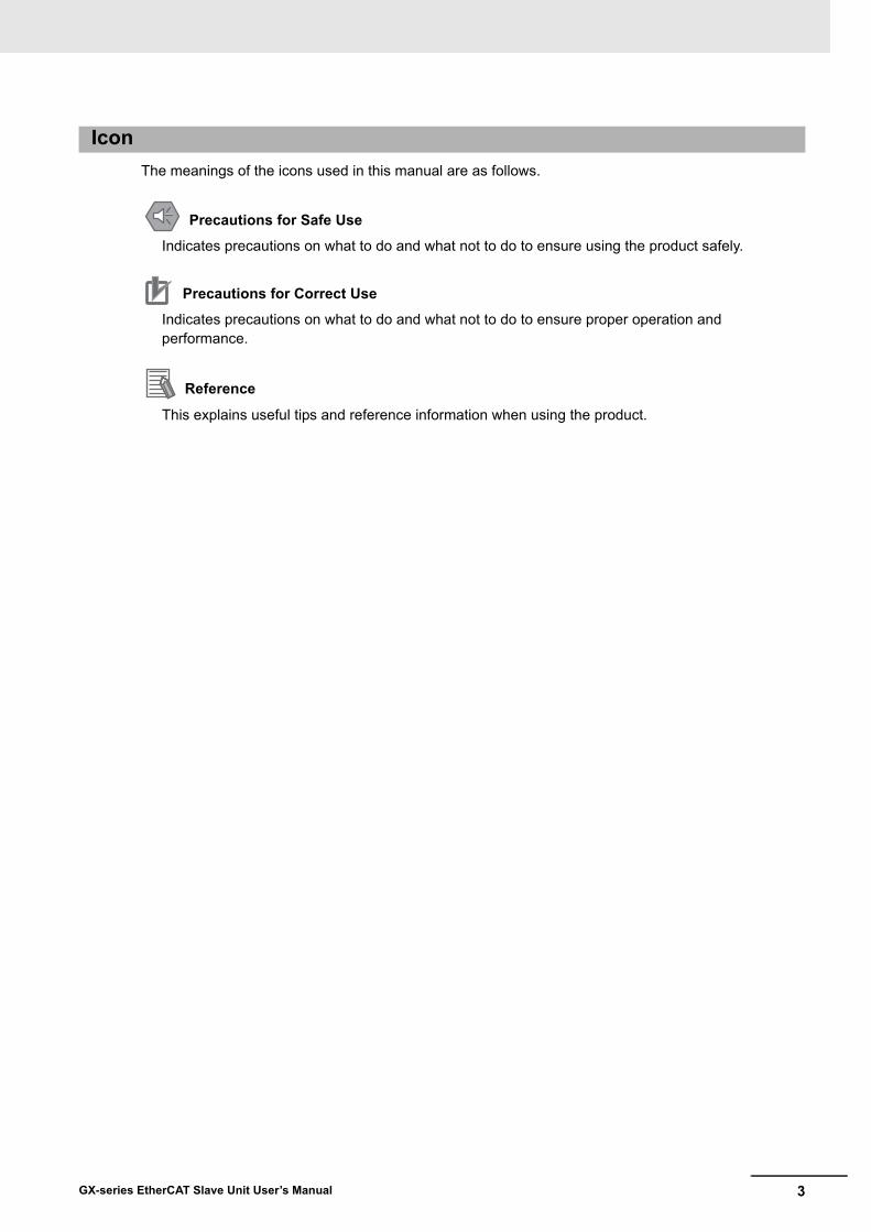
The meanings of the icons used in this manual are as follows.
Indicates precautions on what to do and what not to do to ensure using the product safely.
Indicates precautions on what to do and what not to do to ensure proper operation and performance.
This explains useful tips and reference information when using the product.
Icon
Precautions for Safe Use
Precautions for Correct Use
Reference
4 GX-series EtherCAT Slave Unit User’s Manual
Structure of This Manual
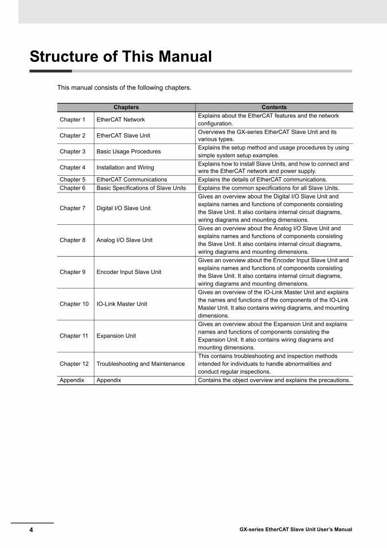
This manual consists of the following chapters.
Chapters Contents
Chapter 1 EtherCAT NetworkExplains about the EtherCAT features and the network configuration.
Chapter 2 EtherCAT Slave Unit Overviews the GX-series EtherCAT Slave Unit and its various types.
Chapter 3 Basic Usage ProceduresExplains the setup method and usage procedures by using simple system setup examples.
Chapter 4 Installation and Wiring Explains how to install Slave Units, and how to connect and wire the EtherCAT network and power supply.
Chapter 5 EtherCAT Communications Explains the details of EtherCAT communications.Chapter 6 Basic Specifications of Slave Units Explains the common specifications for all Slave Units.
Chapter 7 Digital I/O Slave Unit
Gives an overview about the Digital I/O Slave Unit and explains names and functions of components consisting the Slave Unit. It also contains internal circuit diagrams, wiring diagrams and mounting dimensions.
Chapter 8 Analog I/O Slave Unit
Gives an overview about the Analog I/O Slave Unit and explains names and functions of components consisting the Slave Unit. It also contains internal circuit diagrams, wiring diagrams and mounting dimensions.
Chapter 9 Encoder Input Slave Unit
Gives an overview about the Encoder Input Slave Unit and explains names and functions of components consisting the Slave Unit. It also contains internal circuit diagrams, wiring diagrams and mounting dimensions.
Chapter 10 IO-Link Master Unit
Gives an overview of the IO-Link Master Unit and explains the names and functions of the components of the IO-Link Master Unit. It also contains wiring diagrams, and mounting dimensions.
Chapter 11 Expansion Unit
Gives an overview about the Expansion Unit and explains names and functions of components consisting the Expansion Unit. It also contains wiring diagrams and mounting dimensions.
Chapter 12 Troubleshooting and MaintenanceThis contains troubleshooting and inspection methods intended for individuals to handle abnormalities and conduct regular inspections.
Appendix Appendix Contains the object overview and explains the precautions.

5GX-series EtherCAT Slave Unit User’s Manual
Terms and Conditions Agreement
Exclusive WarrantyOmron’s exclusive warranty is that the Products will be free from defects in materials and workmanship for a period of twelve months from the date of sale by Omron (or such other period expressed in writing by Omron). Omron disclaims all other warranties, express or implied.
LimitationsOMRON MAKES NO WARRANTY OR REPRESENTATION, EXPRESS OR IMPLIED, ABOUT NON-INFRINGEMENT, MERCHANTABILITY OR FITNESS FOR A PARTICULAR PURPOSE OF THE PRODUCTS. BUYER ACKNOWLEDGES THAT IT ALONE HAS DETERMINED THAT THE PRODUCTS WILL SUITABLY MEET THE REQUIREMENTS OF THEIR INTENDED USE.Omron further disclaims all warranties and responsibility of any type for claims or expenses based on infringement by the Products or otherwise of any intellectual property right.
Buyer RemedyOmron’s sole obligation hereunder shall be, at Omron’s election, to (i) replace (in the form originally shipped with Buyer responsible for labor charges for removal or replacement thereof) the non-complying Product, (ii) repair the non-complying Product, or (iii) repay or credit Buyer an amount equal to the purchase price of the non-complying Product; provided that in no event shall Omron be responsible for warranty, repair, indemnity or any other claims or expenses regarding the Products unless Omron’s analysis confirms that the Products were properly handled, stored, installed and maintained and not subject to contamination, abuse, misuse or inappropriate modification. Return of any Products by Buyer must be approved in writing by Omron before shipment. Omron Companies shall not be liable for the suitability or unsuitability or the results from the use of Products in combination with any electrical or electronic components, circuits, system assemblies or any other materials or substances or environments. Any advice, recommendations or information given orally or in writing, are not to be construed as an amendment or addition to the above warranty.
See http://www.omron.com/global/ or contact your Omron representative for published information.
OMRON COMPANIES SHALL NOT BE LIABLE FOR SPECIAL, INDIRECT, INCIDENTAL, OR CONSEQUENTIAL DAMAGES, LOSS OF PROFITS OR PRODUCTION OR COMMERCIAL LOSS IN ANY WAY CONNECTED WITH THE PRODUCTS, WHETHER SUCH CLAIM IS BASED IN CONTRACT, WARRANTY, NEGLIGENCE OR STRICT LIABILITY.Further, in no event shall liability of Omron Companies exceed the individual price of the Product on which liability is asserted.
Warranty, Limitations of Liability
Warranties
Limitation on Liability; Etc

6 GX-series EtherCAT Slave Unit User’s Manual
Omron Companies shall not be responsible for conformity with any standards, codes or regulations which apply to the combination of the Product in the Buyer’s application or use of the Product. At Buyer’s request, Omron will provide applicable third party certification documents identifying ratings and limitations of use which apply to the Product. This information by itself is not sufficient for a complete determination of the suitability of the Product in combination with the end product, machine, system, or other application or use. Buyer shall be solely responsible for determining appropriateness of the particular Product with respect to Buyer’s application, product or system. Buyer shall take application responsibility in all cases. NEVER USE THE PRODUCT FOR AN APPLICATION INVOLVING SERIOUS RISK TO LIFE OR PROPERTY WITHOUT ENSURING THAT THE SYSTEM AS A WHOLE HAS BEEN DESIGNED TO ADDRESS THE RISKS, AND THAT THE OMRON PRODUCT(S) IS PROPERLY RATED AND INSTALLED FOR THE INTENDED USE WITHIN THE OVERALL EQUIPMENT OR SYSTEM.
Omron Companies shall not be responsible for the user’s programming of a programmable Product, or any consequence thereof.
Data presented in Omron Company websites, catalogs and other materials is provided as a guide for the user in determining suitability and does not constitute a warranty. It may represent the result of Omron’s test conditions, and the user must correlate it to actual application requirements. Actual performance is subject to the Omron’s Warranty and Limitations of Liability.
Product specifications and accessories may be changed at any time based on improvements and other reasons. It is our practice to change part numbers when published ratings or features are changed, or when significant construction changes are made. However, some specifications of the Product may be changed without any notice. When in doubt, special part numbers may be assigned to fix or establish key specifications for your application. Please consult with your Omron’s representative at any time to confirm actual specifications of purchased Product.
Information presented by Omron Companies has been checked and is believed to be accurate; however, no responsibility is assumed for clerical, typographical or proofreading errors or omissions.
Application Considerations
Suitability of Use
Programmable Products
Disclaimers
Performance Data
Change in Specifications
Errors and Omissions
7GX-series EtherCAT Slave Unit User’s Manual
Safety Precautions
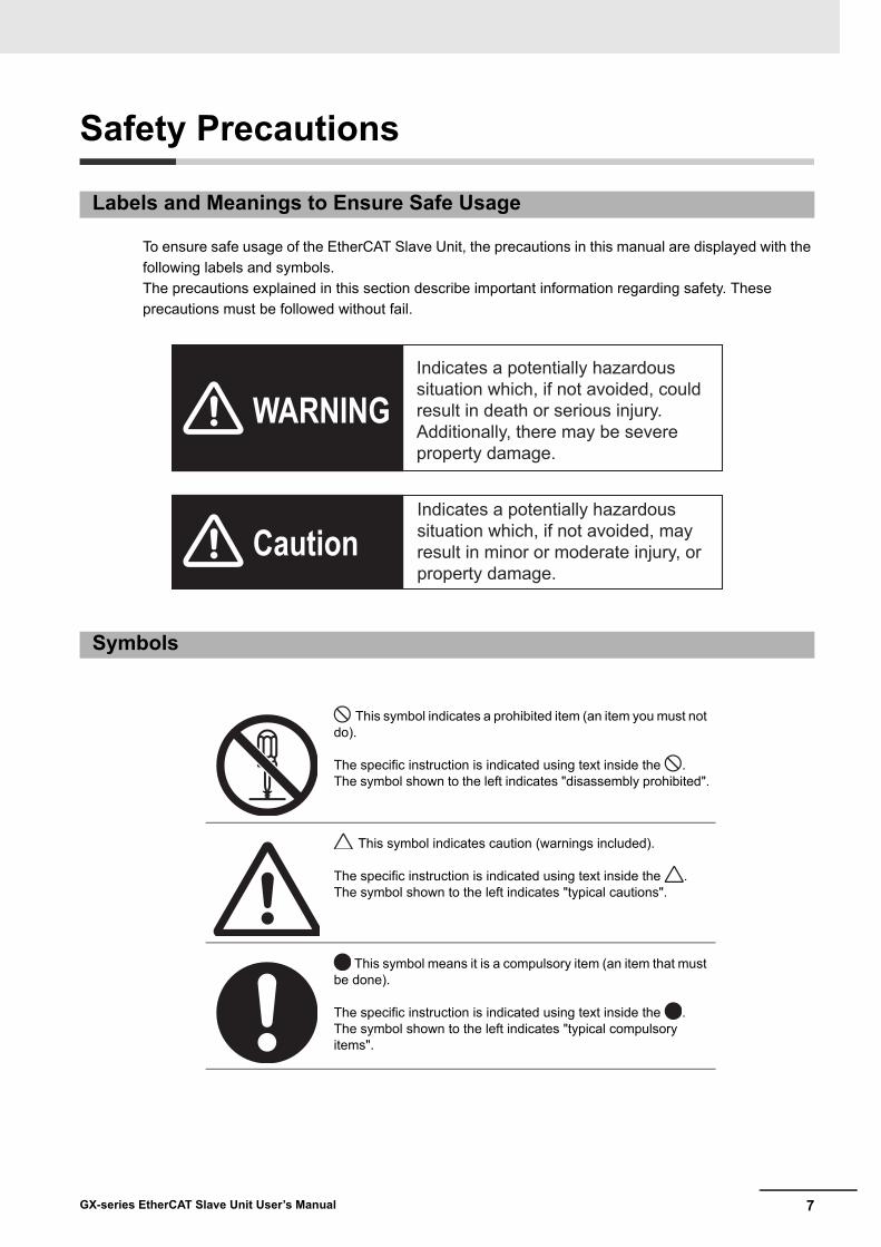
To ensure safe usage of the EtherCAT Slave Unit, the precautions in this manual are displayed with the following labels and symbols.The precautions explained in this section describe important information regarding safety. These precautions must be followed without fail.
Labels and Meanings to Ensure Safe Usage
Symbols
This symbol indicates a prohibited item (an item you must not do).
The specific instruction is indicated using text inside the .The symbol shown to the left indicates "disassembly prohibited".
This symbol indicates caution (warnings included).
The specific instruction is indicated using text inside the .The symbol shown to the left indicates "typical cautions".
This symbol means it is a compulsory item (an item that must be done).
The specific instruction is indicated using text inside the .The symbol shown to the left indicates "typical compulsory items".
WARNING
Caution
Indicates a potentially hazardous situation which, if not avoided, could result in death or serious injury. Additionally, there may be severe property damage.
Indicates a potentially hazardous situation which, if not avoided, may result in minor or moderate injury, or property damage.

8 GX-series EtherCAT Slave Unit User’s Manual
Do not attempt to take any Unit apart and do not touch the interior of any Unit while the power is being supplied. Also, do not turn ON the power supply while the cover is open. Doing any of these may result in electric shock.
Do not attempt to disassemble, repair, or modify any Units. Doing any of these may result in electric shock.
Do not input voltages or currents exceeding the rated range to the Unit.Using voltages or currents exceeding the rated range may cause Unit failure or fire.
Provide safety measures in external circuits (i.e., not in the Units), including the following items, to ensure safety in the system if an abnormality occurs due to malfunction of the PLC or another external factor affecting the PLC operation. ("PLC" includes CPU Units, other Units mounted in the PLC, and Remote I/O Terminals.)Not doing so may result in serious accidents.
Emergency stop circuits, interlock circuits, limit circuits, and similar safety measures must be provided in external control circuits, not in the Units.The PLC will turn OFF all outputs when its self-diagnosis function detects any error or when a severe failure alarm (FALS) instruction is executed. As a countermeasure for such problems, external safety measures must be provided to ensure safety in the system.The Slave Unit outputs may remain ON or OFF due to deposits on or burning of the output relays, or destruction of the output transistors. As a countermeasure for such problems, external safety measures must be provided to ensure safety in the system.When the 24-VDC output (service power supply) is overloaded or short-circuited, the voltage may drop and result in the outputs being turned OFF. As a countermeasure for such problems, external safety measures must be provided to ensure safety in the system.Implement proper measures as part of your communications system or in your program to ensure safety in the system even when a communications error or malfunction occurs during remote I/O communication.
WARNING

9GX-series EtherCAT Slave Unit User’s Manual
The CPU Unit refreshes I/O even when the program is stopped (i.e., even in PROGRAM mode). Confirm safety thoroughly in advance before changing the status of any part of memory allocated to I/O Units, Special I/O Units, or CPU Bus Units. Any changes to the data allocated to any Unit specifically the Special I/O Units/CPU Bus Units may result in unexpected operation of the loads connected to the Unit.
• Transferring I/O memory data to the CPU Unit with a Programming Device (PC tool).
• Changing present values in memory with a Programming Device.• Force-setting/-resetting bits with a Programming Device.• Transferring I/O memory files from a memory card or EM file memory to the CPU
Unit.• Transferring I/O memory from a host computer or from another PLC on a network.
Fail-safe measures must be taken by the customer to ensure safety in the event of incorrect, missing, or abnormal signals caused by broken signal lines, momentary power interruptions, or other causes. Not doing so may result in serious accidents.

10 GX-series EtherCAT Slave Unit User’s Manual
Precautions for Safe Use
Observe the following precautions when using the Unit.
Power Supply• Always use the power supply voltage specified in this manual. An incorrect voltage may result in
malfunction or burning.• Take appropriate measures to ensure that the specified power with the rated voltage and
frequency is supplied. Be particularly careful in places where the power supply is unstable. An incorrect power supply may result in malfunction.
• Always turn OFF the power supply to the PLC, Slave Units and other Units before attempting any of the following. Not turning OFF the power supply may result in malfunction or electric shock.
• Assembling any Units (Expansion Units).• Removing or attaching the terminal blocks or connectors to Slave Unit.• Replacing parts (e.g., relays).• Setting the DIP switch or the node address switches• Connecting cables or wiring the system.
Installation• Before touching a Unit, be sure to first touch a grounded metallic object in order to discharge any
static build-up. Not doing so may result in malfunction or damage.• Make sure that the terminal blocks, communications cables, and other items with locking devices
are properly locked into place. Improver locking may result in malfunction.• Mount the Units securely using DIN track.• Make sure that all Slave Unit mounting screws, cable connector screws, and switch cover screws
are tightened to the torque specified in this manuals. Incorrect tightening torque may result in malfunction.
• Make sure that all terminal block screws are tightened to the torque specified in this manuals. Incorrect tightening torque may result in fire, malfunction, or failure.
• Always use the specified communications cables and connectors.• Do not exceed the ranges that are given in the specifications for the communications distance and
number of connected Units.• When there are multiple systems, keep the cables unbundled and separated by at least 5 mm to
prevent unstable operation due to interference.
Wiring• Turn the power on after checking that the wiring and switch settings are correct.• Use the correct wire tools to wire the Unit.• Confirm the polarity of all terminals before wiring them.• Do not allow foreign matter to enter the Units when wiring and installing the Units.• Observe the following precautions when wiring the communications cable.
• Separate the communications cables from the power lines or high-tension lines.• Do not bend the communications cables past their natural bending radius.• Do not pull on the communications cables.• Do not place heavy objects on top of the communications cables.• Always lay communications cable inside ducts.• Connect both ends of communications cable shielded wires to the connector hoods.
• Turn OFF the power of PLC and all the Slave Units before wiring the communication cables.

11GX-series EtherCAT Slave Unit User’s Manual
• Do not apply voltages to the Input Slave Units in excess of the rated input voltage. Excess voltage or loads may result in burning.
• Do not apply voltages or connect loads to the Outputs Slave Units in excess of the maximum switching capacity. Excess voltage or loads may result in burning.
Handling• When transporting the product, use special packing boxes, and protect it from being exposed to
excessive vibration or impact during transportation.• Do not bend cables past their natural bending radius or pull on cables.• Do not place heavy objects on top of the cables.• After replacing Units, resume operation only after transferring to the new CPU Unit and/or Special
I/O Units the contents of the DM Area, HR Area, and other data required for resuming operation. Not doing so may result in unexpected operation.
• Check the user program for proper execution before actually running it on the Unit. Not checking the program may result in unexpected operation.
• When replacing relays or other parts, be sure to confirm that the ratings of the new part are correct. Not doing so may result in malfunction or burning.
• Confirm that no adverse effect will occur in the system before attempting any of the following. • Changing the operating mode of the CPU Unit (including changing the setting of the
Operating Mode at Startup)• Changing the user program or settings• Changing set values or present values• Forced refreshing
• Always sufficiently check the safety at the connected devices before you change the settings of a slave or Unit.
• Do not use thinner when cleaning. Use commercially available alcohol.• Do not use high-pressure cleaning.• EtherCAT communications are not always established immediately after the power supply is
turned ON. Use the system variables in the user program to confirm that communications are established before attempting control operations.
External Circuits• Install external breakers and take other safety measures against short-circuiting in external wiring.
12 GX-series EtherCAT Slave Unit User’s Manual
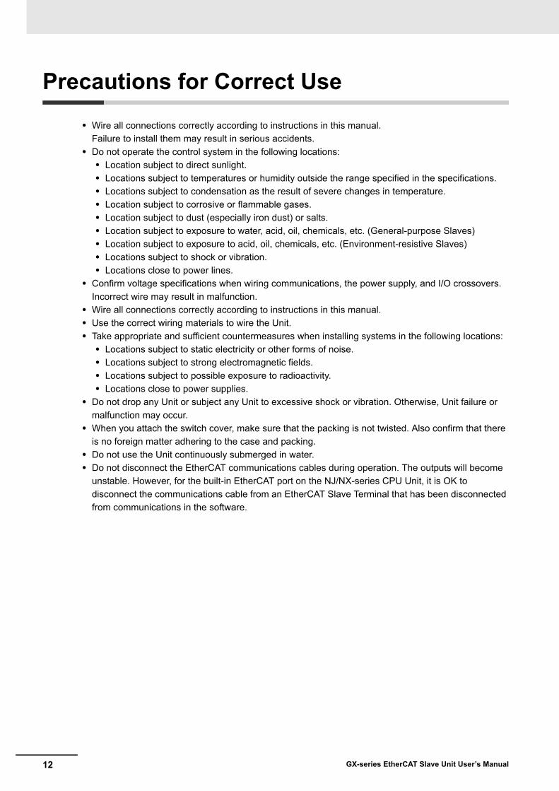
Precautions for Correct Use
• Wire all connections correctly according to instructions in this manual.Failure to install them may result in serious accidents.
• Do not operate the control system in the following locations:• Location subject to direct sunlight.• Locations subject to temperatures or humidity outside the range specified in the specifications.• Locations subject to condensation as the result of severe changes in temperature.• Location subject to corrosive or flammable gases.• Location subject to dust (especially iron dust) or salts.• Location subject to exposure to water, acid, oil, chemicals, etc. (General-purpose Slaves)• Location subject to exposure to acid, oil, chemicals, etc. (Environment-resistive Slaves)• Locations subject to shock or vibration.• Locations close to power lines.
• Confirm voltage specifications when wiring communications, the power supply, and I/O crossovers.Incorrect wire may result in malfunction.
• Wire all connections correctly according to instructions in this manual.• Use the correct wiring materials to wire the Unit.• Take appropriate and sufficient countermeasures when installing systems in the following locations:
• Locations subject to static electricity or other forms of noise.• Locations subject to strong electromagnetic fields.• Locations subject to possible exposure to radioactivity.• Locations close to power supplies.
• Do not drop any Unit or subject any Unit to excessive shock or vibration. Otherwise, Unit failure or malfunction may occur.
• When you attach the switch cover, make sure that the packing is not twisted. Also confirm that there is no foreign matter adhering to the case and packing.
• Do not use the Unit continuously submerged in water.• Do not disconnect the EtherCAT communications cables during operation. The outputs will become
unstable. However, for the built-in EtherCAT port on the NJ/NX-series CPU Unit, it is OK to disconnect the communications cable from an EtherCAT Slave Terminal that has been disconnected from communications in the software.
13GX-series EtherCAT Slave Unit User’s Manual
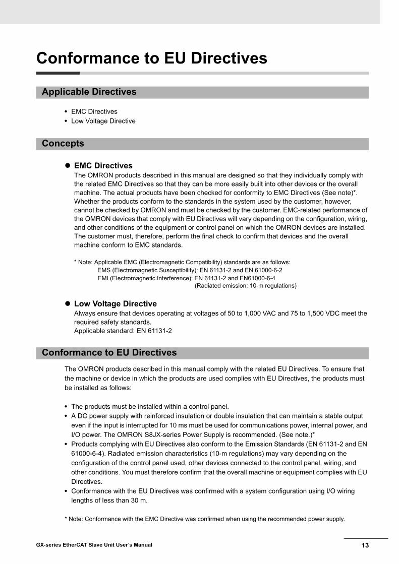
Conformance to EU Directives
• EMC Directives• Low Voltage Directive
EMC DirectivesThe OMRON products described in this manual are designed so that they individually comply with the related EMC Directives so that they can be more easily built into other devices or the overall machine. The actual products have been checked for conformity to EMC Directives (See note)*.Whether the products conform to the standards in the system used by the customer, however, cannot be checked by OMRON and must be checked by the customer. EMC-related performance of the OMRON devices that comply with EU Directives will vary depending on the configuration, wiring, and other conditions of the equipment or control panel on which the OMRON devices are installed.The customer must, therefore, perform the final check to confirm that devices and the overall machine conform to EMC standards.
* Note: Applicable EMC (Electromagnetic Compatibility) standards are as follows: EMS (Electromagnetic Susceptibility): EN 61131-2 and EN 61000-6-2
EMI (Electromagnetic Interference): EN 61131-2 and EN61000-6-4 (Radiated emission: 10-m regulations)
Low Voltage DirectiveAlways ensure that devices operating at voltages of 50 to 1,000 VAC and 75 to 1,500 VDC meet the required safety standards.Applicable standard: EN 61131-2
The OMRON products described in this manual comply with the related EU Directives. To ensure that the machine or device in which the products are used complies with EU Directives, the products must be installed as follows:
• The products must be installed within a control panel.• A DC power supply with reinforced insulation or double insulation that can maintain a stable output
even if the input is interrupted for 10 ms must be used for communications power, internal power, and I/O power. The OMRON S8JX-series Power Supply is recommended. (See note.)*
• Products complying with EU Directives also conform to the Emission Standards (EN 61131-2 and EN 61000-6-4). Radiated emission characteristics (10-m regulations) may vary depending on the configuration of the control panel used, other devices connected to the control panel, wiring, and other conditions. You must therefore confirm that the overall machine or equipment complies with EU Directives.
• Conformance with the EU Directives was confirmed with a system configuration using I/O wiring lengths of less than 30 m.
* Note: Conformance with the EMC Directive was confirmed when using the recommended power supply.
Applicable Directives
Concepts
Conformance to EU Directives

14 GX-series EtherCAT Slave Unit User’s Manual
Observe the following precaution if you use NX-series Units in Korea.
Class A Device (Broadcasting Communications Device for Office Use)This device obtained EMC registration for office use (Class A), and it is intended to be used in places other than homes. Sellers and/or users need to take note of this.
Conformance to KC Standards
15GX-series EtherCAT Slave Unit User’s Manual
Related Manuals
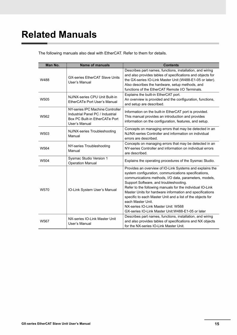
The following manuals also deal with EtherCAT. Refer to them for details.
Man No. Name of manuals Contents
W488GX-series EtherCAT Slave Units User’s Manual
Describes part names, functions, installation, and wiring and also provides tables of specifications and objects for the GX-series IO-Link Master Unit (W488-E1-05 or later). Also describes the hardware, setup methods, and functions of the EtherCAT Remote I/O Terminals.
W505NJ/NX-series CPU Unit Built-in EtherCAT® Port User’s Manual
Explains the built-in EtherCAT port.An overview is provided and the configuration, functions, and setup are described.
W562
NY-series IPC Machine Controller Industrial Panel PC / Industrial Box PC Built-in EtherCAT® Port User’s Manual
Information on the built-in EtherCAT port is provided.This manual provides an introduction and provides information on the configuration, features, and setup.
W503NJ/NX-series Troubleshooting Manual
Concepts on managing errors that may be detected in an NJ/NX-series Controller and information on individual errors are described.
W564NY-series Troubleshooting Manual
Concepts on managing errors that may be detected in an NY-series Controller and information on individual errors are described.
W504Sysmac Studio Version 1 Operation Manual
Explains the operating procedures of the Sysmac Studio.
W570 IO-Link System User’s Manual
Provides an overview of IO-Link Systems and explains the system configuration, communications specifications, communications methods, I/O data, parameters, models, Support Software, and troubleshooting.Refer to the following manuals for the individual IO-Link Master Units for hardware information and specifications specific to each Master Unit and a list of the objects for each Master Unit.NX-series IO-Link Master Unit: W568GX-series IO-Link Master Unit:W488-E1-05 or later
W567NX-series IO-Link Master Unit User’s Manual
Describes part names, functions, installation, and wiring and also provides tables of specifications and NX objects for the NX-series IO-Link Master Unit.
16 GX-series EtherCAT Slave Unit User’s Manual
Version Upgrade Information
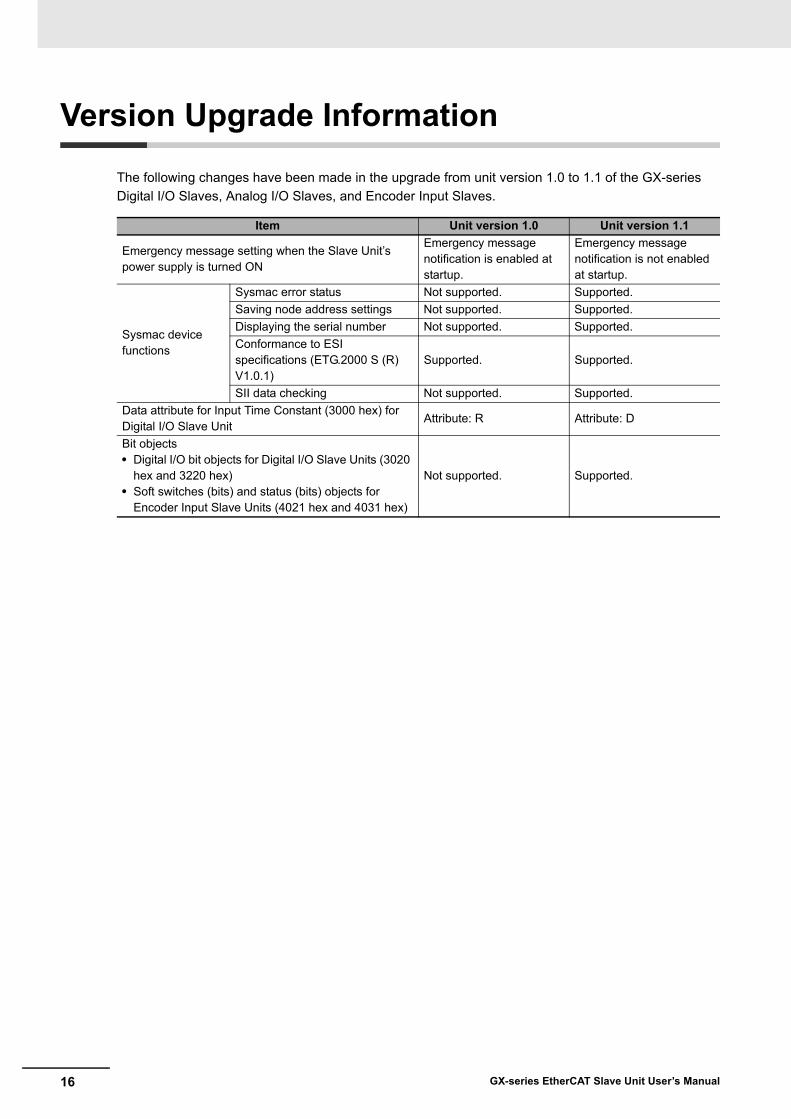
The following changes have been made in the upgrade from unit version 1.0 to 1.1 of the GX-series Digital I/O Slaves, Analog I/O Slaves, and Encoder Input Slaves.
Item Unit version 1.0 Unit version 1.1
Emergency message setting when the Slave Unit’s power supply is turned ON
Emergency message notification is enabled at startup.
Emergency message notification is not enabled at startup.
Sysmac device functions
Sysmac error status Not supported. Supported.Saving node address settings Not supported. Supported.Displaying the serial number Not supported. Supported.Conformance to ESI specifications (ETG.2000 S (R) V1.0.1)
Supported. Supported.
SII data checking Not supported. Supported.Data attribute for Input Time Constant (3000 hex) for Digital I/O Slave Unit
Attribute: R Attribute: D
Bit objects• Digital I/O bit objects for Digital I/O Slave Units (3020
hex and 3220 hex)• Soft switches (bits) and status (bits) objects for
Encoder Input Slave Units (4021 hex and 4031 hex)
Not supported. Supported.

17GX-series EtherCAT Slave Unit User’s Manual

18 GX-series EtherCAT Slave Unit User’s Manual
Contents
Introduction............................................................................................................................ 1-1Intended Readers........................................................................................................ 1-1
How to Read the Manual ....................................................................................................... 1-2Page Structure............................................................................................................. 1-2Icon.............................................................................................................................. 1-3
Structure of This Manual ...................................................................................................... 1-4Terms and Conditions Agreement ....................................................................................... 1-5
Warranty, Limitations of Liability .................................................................................. 1-5Application Considerations.......................................................................................... 1-6Disclaimers.................................................................................................................. 1-6
Safety Precautions ................................................................................................................ 1-7Labels and Meanings to Ensure Safe Usage .............................................................. 1-7Symbols....................................................................................................................... 1-7
Precautions for Safe Use .................................................................................................... 1-10Precautions for Correct Use............................................................................................... 1-12Conformance to EU Directives........................................................................................... 1-13
Applicable Directives ................................................................................................. 1-13Concepts ................................................................................................................... 1-13Conformance to EU Directives .................................................................................. 1-13Conformance to KC Standards.................................................................................. 1-14
Related Manuals .................................................................................................................. 1-15Version Upgrade Information ............................................................................................. 1-16
Chapter 1 EtherCAT Network............................................................. 1-1
1-1 Overview of EtherCAT Networks.......................................................................................... 1-21-1-1 Features of EtherCAT.................................................................................................. 1-21-1-2 Structure of EtherCAT ................................................................................................. 1-21-1-3 Communications types of EtherCAT ........................................................................... 1-41-1-4 Connection Examples of EtherCAT............................................................................. 1-5
1-2 Configuration Elements of EtherCAT Network ................................................................... 1-61-2-1 Configuration Devices of EtherCAT Network .............................................................. 1-61-2-2 Overview of Configuration Devices ............................................................................. 1-7
Chapter 2 EtherCAT Slave Unit ......................................................... 2-1
2-1 Overview of EtherCAT Slave Unit ........................................................................................ 2-22-1-1 Slave Units Usage....................................................................................................... 2-22-1-2 Features of GX-series EtherCAT Slave Units ............................................................. 2-2
2-2 Types of EtherCAT Slave Units ............................................................................................ 2-32-2-1 Slave Units List............................................................................................................ 2-32-2-2 Installation, I/O Connection, and Power Supply Methods for Each Slave Unit ........... 2-6
Chapter 3 Basic Usage Procedures .................................................. 3-1
3-1 Setup Examples and Basic Procedure ................................................................................ 3-23-1-1 System Setting Examples ........................................................................................... 3-23-1-2 Basic Procedure .......................................................................................................... 3-3

19GX-series EtherCAT Slave Unit User’s Manual
3-2 Setting and Wiring Hardware ............................................................................................... 3-43-2-1 Mounting and Setting EtherCAT Master Unit .............................................................. 3-43-2-2 Mounting and Setting Slave Units ............................................................................... 3-43-2-3 Wiring Communications Cables .................................................................................. 3-43-2-4 Connecting Power Supplies ........................................................................................ 3-43-2-5 Wiring I/O Devices....................................................................................................... 3-4
3-3 Starting Communications ..................................................................................................... 3-53-3-1 Starting a System ........................................................................................................ 3-53-3-2 Setting EtherCAT Communications............................................................................. 3-53-3-3 Starting EtherCAT Communications............................................................................ 3-5
3-4 Checking Operations ............................................................................................................ 3-63-4-1 Checking Unit Displays ............................................................................................... 3-63-4-2 Confirming Data Read and Write ................................................................................ 3-63-4-3 Setting Slave Unit Parameter ...................................................................................... 3-6
Chapter 4 Installation and Wiring...................................................... 4-1
4-1 Mounting Slave Units ............................................................................................................ 4-24-1-1 Mounting Preparation .................................................................................................. 4-24-1-2 Mounting Direction ...................................................................................................... 4-24-1-3 Mounting Method......................................................................................................... 4-24-1-4 Removal Method ......................................................................................................... 4-3
4-2 Connecting to EtherCAT Network........................................................................................ 4-44-2-1 Precautions for Network Connection........................................................................... 4-44-2-2 Preparation for Connecting Network ........................................................................... 4-54-2-3 Connecting Communications Cables and Connectors................................................ 4-64-2-4 Connecting to Communications Cables ...................................................................... 4-7
4-3 Connecting to Unit Power Supply and I/O Power Supply.................................................. 4-84-3-1 Precautions at Supplying Unit Power and I/O Power .................................................. 4-84-3-2 Unit Power Supply Specifications................................................................................ 4-94-3-3 Connecting the Unit Power Supply.............................................................................. 4-94-3-4 Connecting the I/O Power Supply ............................................................................. 4-11
4-4 Connecting an External Device.......................................................................................... 4-134-4-1 Connecting to a Screw Terminal Block...................................................................... 4-134-4-2 Connecting to e-CON Connector Terminals .............................................................. 4-144-4-3 Connecting the M12 Connector................................................................................. 4-17
Chapter 5 EtherCAT Communications.............................................. 5-1
5-1 Structure of CAN application protocol over EtherCAT (CoE)............................................ 5-25-2 EtherCAT Slave Information File (ESI File) ......................................................................... 5-35-3 Communications State Transitions...................................................................................... 5-45-4 Process Data Objects (PDO)................................................................................................. 5-5
5-4-1 Overview ..................................................................................................................... 5-55-4-2 PDO Mapping Settings................................................................................................ 5-55-4-3 Sync Manager PDO Assignment Settings................................................................... 5-65-4-4 Fixed PDO Mapping .................................................................................................... 5-7
5-5 Service Data Object (SDO).................................................................................................. 5-105-5-1 Overview ................................................................................................................... 5-105-5-2 Abort Codes .............................................................................................................. 5-10
5-6 EtherCAT Master Unit - Slave Unit Communications....................................................... 5-115-6-1 FREE RUN Mode...................................................................................................... 5-115-6-2 DC Mode ................................................................................................................... 5-11
20 GX-series EtherCAT Slave Unit User’s Manual
5-7 Emergency Messages ......................................................................................................... 5-135-7-1 Emergency Message Notification.............................................................................. 5-135-7-2 Diagnosis History ...................................................................................................... 5-14
5-8 Sysmac Device Functions .................................................................................................. 5-15
Chapter 6 Basic Specifications of Slave Units................................. 6-1
6-1 EtherCAT Communications Specifications......................................................................... 6-26-2 General Specifications.......................................................................................................... 6-36-3 Specifications of Common Areas ........................................................................................ 6-4
6-3-1 Status Indicators.......................................................................................................... 6-46-3-2 Node Address Setting Switches .................................................................................. 6-66-3-3 Communications Connectors ...................................................................................... 6-86-3-4 Unit Power Supply Connector ................................................................................... 6-116-3-5 I/O Power Supply Connector..................................................................................... 6-13
Chapter 7 Digital I/O Slave Unit ......................................................... 7-1
7-1 Digital I/O Slave Unit ............................................................................................................. 7-27-2 I/O Data Allocation (PDO Mapping)...................................................................................... 7-3
7-2-1 Input Data Allocation ................................................................................................... 7-37-2-2 Output Data Allocation ................................................................................................ 7-5
7-3 Functions of Digital I/O Slave Units ..................................................................................... 7-77-3-1 Input Filter ................................................................................................................... 7-77-3-2 Error Mode Output....................................................................................................... 7-8
7-4 Specifications for Each Slave Unit ...................................................................................... 7-97-4-1 2-tier Terminal Block Type 16-point Input Slave Unit GX-ID1611/ID1621 ................. 7-107-4-2 2-tier Terminal Block Type 16-point Output Slave Unit GX-OD1611/OD1621........... 7-147-4-3 2-tier Terminal Block Relay Type 16-point Output Slave Unit GX-OC1601............... 7-187-4-4 2-tier Terminal Block Type 8-point Input and 8-point Output Slave Unit
GX-MD1611/MD1621 ................................................................................................ 7-227-4-5 3-tier Terminal Block Type 16-point Input Slave Unit GX-ID1612/ID1622 ................. 7-287-4-6 3-tier Terminal Block Type 16-point Output Slave Unit GX-OD1612/OD1622........... 7-337-4-7 3-tier Terminal Block Type 8-point Input and 8-point Output Slave Unit
GX-MD1612/MD1622................................................................................................ 7-387-4-8 e-CON Connector Type 16-point Input Slave Unit GX-ID1618/ID1628..................... 7-447-4-9 e-CON Connector Type 16-point Output Slave Unit GX-OD1618/OD1628 .............. 7-487-4-10 e-CON Connector Type 8-point Input and 8-point Output Slave Unit
GX-MD1618/MD1628................................................................................................ 7-537-4-11 e-CON Connector Type 32-point Input Slave Unit GX-ID3218/ID3228..................... 7-597-4-12 e-CON Connector Type 32-point Output Slave Unit GX-OD3218/OD3228 .............. 7-647-4-13 e-CON Connector Type 16-point Input and 16-point Output Slave Unit
GX-MD3218/MD3228................................................................................................ 7-697-5 Mounting Dimensions ......................................................................................................... 7-75
7-5-1 2-tier Terminal Block Type ......................................................................................... 7-757-5-2 3-tier Terminal Block Type ......................................................................................... 7-767-5-3 e-CON Connector Type............................................................................................. 7-77
Chapter 8 Analog I/O Slave Unit........................................................ 8-1
8-1 Analog I/O Slave Unit ............................................................................................................ 8-2
21GX-series EtherCAT Slave Unit User’s Manual
8-2 Overview of the Analog Input Slave Unit ............................................................................ 8-38-2-1 Input Range and Converted Data................................................................................ 8-38-2-2 I/O Data Allocation (PDO Mapping) ............................................................................ 8-6
8-3 Function of the Analog Input Slave Unit ............................................................................. 8-78-3-1 AD Conversion Available Point Setting ....................................................................... 8-78-3-2 Moving Average .......................................................................................................... 8-88-3-3 Disconnected Line Detection..................................................................................... 8-108-3-4 User adjustment ........................................................................................................ 8-10
8-4 Overview of the Analog Output Slave Unit ....................................................................... 8-128-4-1 Output Range and Converted Data........................................................................... 8-128-4-2 I/O Data Allocation (PDO Mapping) .......................................................................... 8-14
8-5 Function of the Analog Output Slave Unit ........................................................................ 8-158-5-1 DA Conversion Available Point Setting ..................................................................... 8-158-5-2 Analog Output Fault Action ....................................................................................... 8-168-5-3 User Adjustment........................................................................................................ 8-17
8-6 Overview of Each Slave Unit Type ..................................................................................... 8-188-6-1 4-point Input Slave Unit GX-AD0471......................................................................... 8-198-6-2 2-point Output Slave Unit GX-DA0271...................................................................... 8-23
8-7 Mounting Dimensions ......................................................................................................... 8-27
Chapter 9 Encoder Input Slave Unit.................................................. 9-1
9-1 Encoder Input Slave Unit ...................................................................................................... 9-29-2 I/O Data Allocation................................................................................................................. 9-3
9-2-1 Input Data Allocation ................................................................................................... 9-39-2-2 Output Data Allocation ................................................................................................ 9-6
9-3 Function of the Encoder Input Slave Units ......................................................................... 9-89-3-1 Count Mode................................................................................................................. 9-89-3-2 Circular Counter .......................................................................................................... 9-89-3-3 Input Signal Types....................................................................................................... 9-99-3-4 Encoder Direction Setting.......................................................................................... 9-119-3-5 Counter Reset ........................................................................................................... 9-129-3-6 Counter Preset .......................................................................................................... 9-139-3-7 Counter value latch ................................................................................................... 9-13
9-4 Specifications for Each Slave Unit .................................................................................... 9-149-4-1 Open collector input type GX-EC0211 ...................................................................... 9-159-4-2 Line Driver Input Type GX-EC0241........................................................................... 9-23
9-5 Mounting Dimensions ......................................................................................................... 9-30
Chapter 10 IO-Link Master Unit ......................................................... 10-1
10-1 What Is an IO-Link Master Unit? ........................................................................................ 10-210-1-1 Introduction................................................................................................................ 10-210-1-2 Connection Configuration for EtherCAT Communications Master Unit
and IO-Link Devices .................................................................................................. 10-210-2 I/O Data Allocations: PDO Mapping................................................................................... 10-3
10-2-1 Allocating Input Data ................................................................................................. 10-310-2-2 Allocating Output Data .............................................................................................. 10-4
10-3 Functions of the IO-Link Master Unit................................................................................. 10-510-4 Specifications ...................................................................................................................... 10-7
10-4-1 Specifications ............................................................................................................ 10-710-4-2 Part Names and Functions...................................................................................... 10-11
10-5 Mounting Dimensions ....................................................................................................... 10-15

22 GX-series EtherCAT Slave Unit User’s Manual
10-6 Communications Performance ........................................................................................ 10-1610-6-1 Maximum I/O Response Time................................................................................. 10-1610-6-2 Determining the IO-Link Communications Cycle..................................................... 10-18
10-7 Connected Device Specifications and Models ............................................................... 10-19
Chapter 11 Expansion Unit ................................................................ 11-1
11-1 Overview of the Expansion Unit......................................................................................... 11-211-1-1 Connecting Expansion Units ..................................................................................... 11-211-1-2 I/O Power Supply ...................................................................................................... 11-3
11-2 Specifications of Expansion Unit....................................................................................... 11-411-2-1 8-point Input Expansion Unit XWT-ID08/ID08-1........................................................ 11-511-2-2 8-point Output Expansion Unit XWT-OD08/OD08-1 ................................................. 11-811-2-3 16-point Input Expansion Unit XWT-ID16/ID16-1.....................................................11-1111-2-4 16-point Output Expansion Unit XWT-OD16/OD16-1 ............................................. 11-14
11-3 Mounting Dimensions ....................................................................................................... 11-17
Chapter 12 Troubleshooting and Maintenance................................ 12-1
12-1 Troubleshooting .................................................................................................................. 12-212-1-1 Errors that Can be Checked with Status Indicator and Actions to Take .................... 12-212-1-2 Errors Unique to Each Slave Unit.............................................................................. 12-712-1-3 Error Notification Methods and Types ..................................................................... 12-1312-1-4 Sysmac Error Status Codes .................................................................................... 12-1412-1-5 Emergency Error Code............................................................................................ 12-1912-1-6 Application Layer Status Codes .............................................................................. 12-21
12-2 Equipment Maintenance ................................................................................................... 12-2312-2-1 Cleaning .................................................................................................................. 12-2312-2-2 Inspections .............................................................................................................. 12-2312-2-3 Handling when Replacing Units .............................................................................. 12-2412-2-4 Replacing the IO-Link Master Unit or IO-Link Devices............................................ 12-24
Chapter A Appendix............................................................................A-1
A-1 Object Dictionary...................................................................................................................A-2A-1-1 Object Dictionary Area ................................................................................................A-2A-1-2 Data Types ..................................................................................................................A-2A-1-3 Object Description Format...........................................................................................A-3A-1-4 Communication Objects ..............................................................................................A-4A-1-5 PDO Mapping Object ..................................................................................................A-8A-1-6 Sync Manager Communication Object......................................................................A-24A-1-7 Manufacturer Specific Objects...................................................................................A-29
A-2 Current Consumption Summary ........................................................................................A-67A-2-1 Digital I/O Slave Unit .................................................................................................A-67A-2-2 Analog I/O Slave Unit ................................................................................................A-67A-2-3 Encoder Input Slave Unit...........................................................................................A-67A-2-4 IO-Link Master Unit ...................................................................................................A-68A-2-5 Expansion Unit ..........................................................................................................A-68
A-3 Precautions with Connecting Two-wire DC Sensors .......................................................A-69A-3-1 Relation between ON Voltage of a Unit with DC Inputs
and Sensor Residual Voltage ....................................................................................A-69A-3-2 Relation between ON Current of a Unit with DC Inputs and Sensor Control Output.A-69A-3-3 Relation between OFF Current of a Unit with DC Inputs
and Sensor Leakage Current ....................................................................................A-70

23GX-series EtherCAT Slave Unit User’s Manual
A-4 Wiring External Output Signal Lines .................................................................................A-71A-5 I/O Power Supply Current ...................................................................................................A-72A-6 Glossary ...............................................................................................................................A-74
INDEX

24 GX-series EtherCAT Slave Unit User’s Manual

1 - 1
1
GX-series EtherCAT Slave Unit User’s Manual
This chapter explains the overview of EtherCAT network.
1-1 Overview of EtherCAT Networks . . . . . . . . . . . . . . . . . . . . . . . . . . . . . . . . . 1-21-1-1 Features of EtherCAT . . . . . . . . . . . . . . . . . . . . . . . . . . . . . . . . . . . . . . . . . . . . 1-21-1-2 Structure of EtherCAT . . . . . . . . . . . . . . . . . . . . . . . . . . . . . . . . . . . . . . . . . . . . 1-21-1-3 Communications types of EtherCAT . . . . . . . . . . . . . . . . . . . . . . . . . . . . . . . . . 1-41-1-4 Connection Examples of EtherCAT . . . . . . . . . . . . . . . . . . . . . . . . . . . . . . . . . 1-5
1-2 Configuration Elements of EtherCAT Network . . . . . . . . . . . . . . . . . . . . . . 1-61-2-1 Configuration Devices of EtherCAT Network . . . . . . . . . . . . . . . . . . . . . . . . . . 1-61-2-2 Overview of Configuration Devices . . . . . . . . . . . . . . . . . . . . . . . . . . . . . . . . . . 1-7
EtherCAT Network

1 EtherCAT Network
1 - 2 GX-series EtherCAT Slave Unit User’s Manual
1-1 Overview of EtherCAT Networks
EtherCAT (Ethernet Control Automation Technology) is a high-performance industrial network system based on Ethernet system and can realize faster and more efficient communications.Each node achieves a short communications cycle time by transmitting Ethernet frames at high speed.Furthermore, even though EtherCAT is a unique protocol, it offers excellent general-purpose applicability. For example, you can use Ethernet cables because EtherCAT utilizes standard Ethernet technology for the physical layer. And the effectiveness of EtherCAT can be fully utilized not only in large control systems that require high processing speeds and system integrity, but also in small and medium control systems.
EtherCAT has the following features.
Extremely high-speed communications with speed of 100 MbpsIt dramatically shortens the I/O response time from generation of input signals to transmission of output signals. By fully utilizing the optimized Ethernet frame bandwidth to transfer data using a high-speed repeat method, it is possible to efficiently transmit a wide variety of data.
Extremely High Compatibility with EthernetEtherCAT is an open network with extremely high compatibility with conventional Ethernet systems.
EtherCAT does not send data to individual slave nodes on the network, instead, it passes Ethernet frames through all of the slave nodes.When frame passes through a slave node, the slave node reads and writes data in the areas allocatedto it in the frames in a few nanoseconds.Ethernet frames sent from the EtherCAT Master Unit go through all the EtherCAT Slave Units without stopping on the way. Once they reach the final Slave Unit, they are sent back from the final Slave Unit, pass through all Slave Units again, and return to the EtherCAT Master Unit. With this structure, EtherCAT secures high-speed and real-time data transmission.
1-1-1 Features of EtherCAT
1-1-2 Structure of EtherCAT
EtherCATMaster Unit
Slave Unit Slave Unit Slave Unit
Ethernet frame
INOUT
Data
• Reading output data addressed to the local Slave Units• Writing input data
1 - 3
1 EtherCAT Network
GX-series EtherCAT Slave Unit User’s Manual
1-1 Overview
of EtherCAT
Netw
orks
1
1-1-2 Structure of EtherC
AT
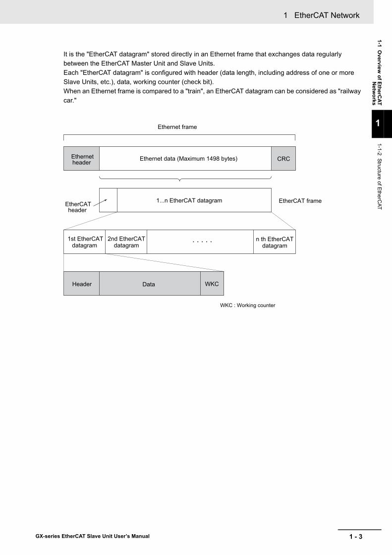
It is the "EtherCAT datagram" stored directly in an Ethernet frame that exchanges data regularly between the EtherCAT Master Unit and Slave Units. Each "EtherCAT datagram" is configured with header (data length, including address of one or more Slave Units, etc.), data, working counter (check bit).When an Ethernet frame is compared to a "train", an EtherCAT datagram can be considered as "railway car."
Ethernetheader CRC Ethernet data (Maximum 1498 bytes)
DataHeader WKC
1...n EtherCAT datagramEtherCATheader
1st EtherCATdatagram
2nd EtherCATdatagram
n th EtherCATdatagram
. . . . .
EtherCAT frame
Ethernet frame
WKC : Working counter
1 EtherCAT Network
1 - 4 GX-series EtherCAT Slave Unit User’s Manual
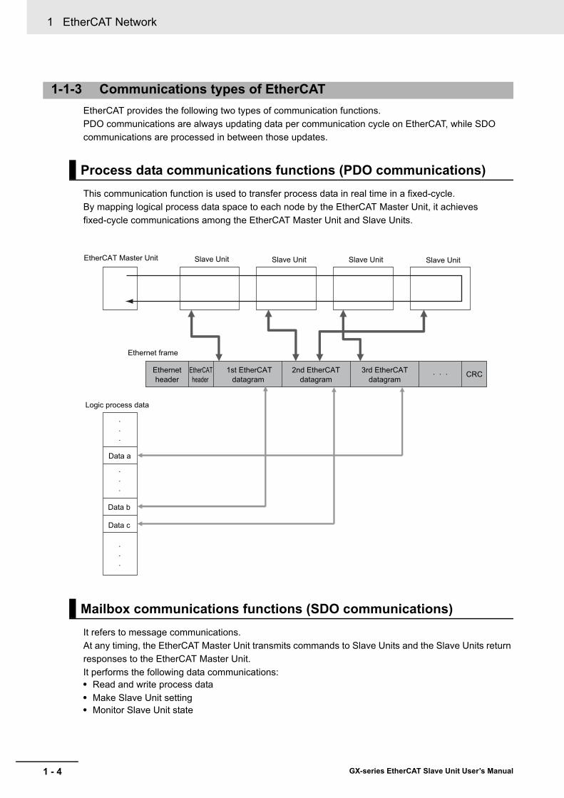
EtherCAT provides the following two types of communication functions.PDO communications are always updating data per communication cycle on EtherCAT, while SDO communications are processed in between those updates.
This communication function is used to transfer process data in real time in a fixed-cycle.By mapping logical process data space to each node by the EtherCAT Master Unit, it achieves fixed-cycle communications among the EtherCAT Master Unit and Slave Units.
It refers to message communications.At any timing, the EtherCAT Master Unit transmits commands to Slave Units and the Slave Units return responses to the EtherCAT Master Unit.It performs the following data communications:• Read and write process data• Make Slave Unit setting• Monitor Slave Unit state
1-1-3 Communications types of EtherCAT
Process data communications functions (PDO communications)
Mailbox communications functions (SDO communications)
EtherCAT Master Unit Slave Unit
Ethernet frame
Slave Unit Slave Unit Slave Unit
Logic process data
.
.
.
.
.
.
.
.
.
Data a
Data b
Data c
Ethernetheader
EtherCATheader
1st EtherCATdatagram
2nd EtherCATdatagram
3rd EtherCATdatagram
CRC. . .

1 - 5
1 EtherCAT Network
GX-series EtherCAT Slave Unit User’s Manual
1-1 Overview
of EtherCAT
Netw
orks
1
1-1-4 Connection Exam
ples of EtherC
AT
This section explains the connection examples of EtherCAT network.
1-1-4 Connection Examples of EtherCAT
ID211
01
32
45
76
89
1110
1213
1415
DC24V7mA
COM
MACHNo.
AD042RUNERCERH
B1 A1
x101
x100
0
9876
5
4 321
0
9876
5
4 321
0 1 2 3 4 5 6 78 9 10 11 12 13 14 15
ADR ADRADR
Digital I/O Slave Unit
EtherCAT Master Unit
Servo Drive
Servomotor
Inverter
IO-Link deviceIO-Link
IO-Link Master Unit

1 EtherCAT Network
1 - 6 GX-series EtherCAT Slave Unit User’s Manual
1-2 Configuration Elements of EtherCAT Network
This section explains the configuration devices and usages of EtherCAT network.
The devices composing an EtherCAT network are shown in the figure below.
1-2-1 Configuration Devices of EtherCAT Network
ID211
01
32
45
76
89
1110
1213
1415
DC24V7mA
COM
MACHNo.
AD042RUNERCERH
B1 A1
x101
x100
0
9876
5
4 321
0
9876
5
4 321
0 1 2 3 4 5 6 78 9 10 11 12 13 14 15
ADRADRADR
ESI file
PC(Configuration Tool)
Peripheral port connection
RS-232C port connection
Communications cable
Unit power supply
I/O power supply
Digital I/O Slave Unit
Analog I/O Slave Unit
Servo Drive Inverter
Communications Unit
EtherCAT Master Unit
IO-Link device
IO-Link
IO-Link Master Unit
1 - 7
1 EtherCAT Network
GX-series EtherCAT Slave Unit User’s Manual
1-2 Configuration Elem
ents ofEtherC
AT Netw
ork
1
1-2-2 Overview
of Configuration D
evices
The overview of each configuration device is as follows:
Administers the EtherCAT network, monitors the state of Slave Units, exchanges I/O data with Slave Units.
Outputs data received from the EtherCAT Master Unit through the EtherCAT network, or sends input data to the EtherCAT Slave Unit through the EtherCAT network. There are Digital I/O Slave Units, Analog I/O Slave Units, and an IO-Link Master Unit.
By mounting to an inverter and other devices, it is possible to serve as a Slave Unit in the EtherCAT network.
It is a PC software for making setting of the EtherCAT network and each Slave Unit. It can be used either by connecting to the EtherCAT Master Unit or as a substitute of the EtherCAT Master Unit.
Uses cables of Ethernet category 5 (100BASE-TX) or higher, with double-shield (aluminum tape and braided shielding), which are connected straight.
Describes information specific to EtherCAT Slave Units in XML format.By reading this file into the Configuration Tool, it is possible to perform various settings such as mapping of Slave Units to I/O memory easily.
Provides power for communications of each Slave Unit and internal operations.Separate them from the I/O power supply when wiring.
Provides power for input/output operations of external devices connected to Slave Units.Separate from Unit power supply when wiring.
1-2-2 Overview of Configuration Devices
EtherCAT Master Unit
EtherCAT Slave Unit
Communications Unit
Configuration Tool
Communications cable
ESI (EtherCAT Slave Information) file
Unit power supply
I/O power supply

1 EtherCAT Network
1 - 8 GX-series EtherCAT Slave Unit User’s Manual
2 - 1
2
GX-series EtherCAT Slave Unit User’s Manual
This chapter explains the overview of EtherCAT Slave Unit.
2-1 Overview of EtherCAT Slave Unit . . . . . . . . . . . . . . . . . . . . . . . . . . . . . . . . . 2-22-1-1 Slave Units Usage . . . . . . . . . . . . . . . . . . . . . . . . . . . . . . . . . . . . . . . . . . . . . . 2-22-1-2 Features of GX-series EtherCAT Slave Units . . . . . . . . . . . . . . . . . . . . . . . . . . 2-2
2-2 Types of EtherCAT Slave Units . . . . . . . . . . . . . . . . . . . . . . . . . . . . . . . . . . . 2-32-2-1 Slave Units List . . . . . . . . . . . . . . . . . . . . . . . . . . . . . . . . . . . . . . . . . . . . . . . . . 2-32-2-2 Installation, I/O Connection, and Power Supply Methods for Each Slave Unit . 2-6
EtherCAT Slave Unit

2 EtherCAT Slave Unit
2 - 2 GX-series EtherCAT Slave Unit User’s Manual
2-1 Overview of EtherCAT Slave Unit
This section explains the overview of EtherCAT Slave Unit.
Slave Units supported by this manual are largely classified into the following types by the their intended purposes.
Digital I/O Slave UnitInputs and outputs digital ON/OFF signals.
Analog I/O Slave UnitPerforms AD or DA conversion for analog signals of 0 to 5 V, 4 to 20 mA, and so on and inputs or outputs them.
Encoder Input Slave UnitPerforms conversion for pulse input signals from an encoder.
IO-Link Master UnitAn IO-Link Master Unit connects to IO-Link devices and general-purpose (i.e., non-IO-Link) devices and it performs IO-Link communications, and input and output of digital ON/OFF signals.
Expansion UnitMounted on a Digital I/O Slave Unit in order to expand the number of I/O points. Note, however, Expansion Units can only be mounted on Digital I/O Slave Units with 2-tier terminal block and 16 points.
The GX-series EtherCAT Slave Units have the following features.
You can use GX-series EtherCAT Slave Units together with NJ/NX-series Machine Automation Controllers and the Sysmac Studio Automation Software to achieve optimum functionality and ease of operation. A GX-series EtherCAT Slave Unit is classified as a Sysmac device.** “Sysmac devices” is a generic name for EtherCAT Slave Units and other OMRON control components that were
designed with the same communications and user interface specifications.
2-1-1 Slave Units Usage
2-1-2 Features of GX-series EtherCAT Slave Units
Optimum Functionality and Ease of Operation Based on Unified Specifications
2 - 3
2 EtherCAT Slave Unit
GX-series EtherCAT Slave Unit User’s Manual
2-2 Types of EtherCAT Slave U
nits
2
2-2-1 Slave U
nits List
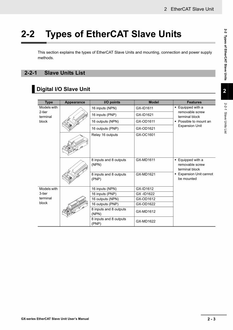
2-2 Types of EtherCAT Slave Units
This section explains the types of EtherCAT Slave Units and mounting, connection and power supply methods.
2-2-1 Slave Units List
Digital I/O Slave Unit
Type Appearance I/O points Model FeaturesModels with 2-tier terminal block
16 inputs (NPN) GX-ID1611 • Equipped with a removable screw terminal block
• Possible to mount an Expansion Unit
16 inputs (PNP) GX-ID1621
16 outputs (NPN) GX-OD1611
16 outputs (PNP) GX-OD1621
Relay 16 outputs GX-OC1601
8 inputs and 8 outputs(NPN)
GX-MD1611 • Equipped with a removable screw terminal block
• Expansion Unit cannot be mounted
8 inputs and 8 outputs(PNP)
GX-MD1621
Models with 3-tier terminal block
16 inputs (NPN) GX-ID161216 inputs (PNP) GX -ID162216 outputs (NPN) GX-OD161216 outputs (PNP) GX-OD16228 inputs and 8 outputs(NPN)
GX-MD1612
8 inputs and 8 outputs(PNP)
GX-MD1622
2 EtherCAT Slave Unit
2 - 4 GX-series EtherCAT Slave Unit User’s Manual
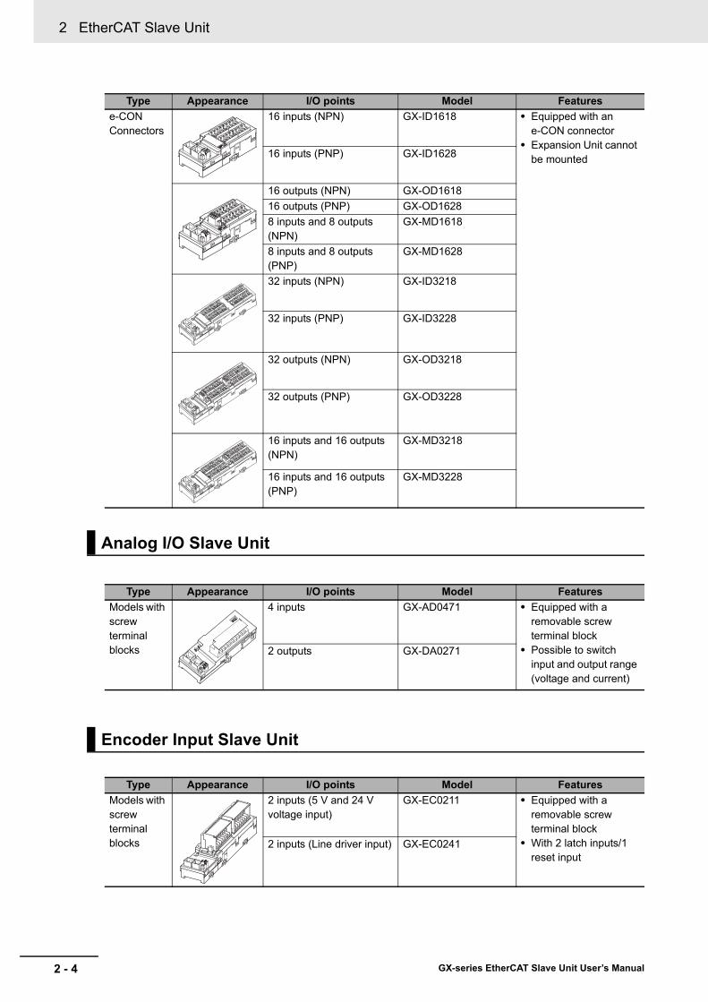
e-CONConnectors
16 inputs (NPN) GX-ID1618 • Equipped with an e-CON connector
• Expansion Unit cannot be mounted16 inputs (PNP) GX-ID1628
16 outputs (NPN) GX-OD161816 outputs (PNP) GX-OD16288 inputs and 8 outputs(NPN)
GX-MD1618
8 inputs and 8 outputs(PNP)
GX-MD1628
32 inputs (NPN) GX-ID3218
32 inputs (PNP) GX-ID3228
32 outputs (NPN) GX-OD3218
32 outputs (PNP) GX-OD3228
16 inputs and 16 outputs(NPN)
GX-MD3218
16 inputs and 16 outputs(PNP)
GX-MD3228
Analog I/O Slave Unit
Type Appearance I/O points Model FeaturesModels with screw terminal blocks
4 inputs GX-AD0471 • Equipped with a removable screw terminal block
• Possible to switch input and output range (voltage and current)
2 outputs GX-DA0271
Encoder Input Slave Unit
Type Appearance I/O points Model FeaturesModels with screw terminal blocks
2 inputs (5 V and 24 V voltage input)
GX-EC0211 • Equipped with a removable screw terminal block
• With 2 latch inputs/1 reset input
2 inputs (Line driver input) GX-EC0241
Type Appearance I/O points Model Features
2 - 5
2 EtherCAT Slave Unit
GX-series EtherCAT Slave Unit User’s Manual
2-2 Types of EtherCAT Slave U
nits
2
2-2-1 Slave U
nits List
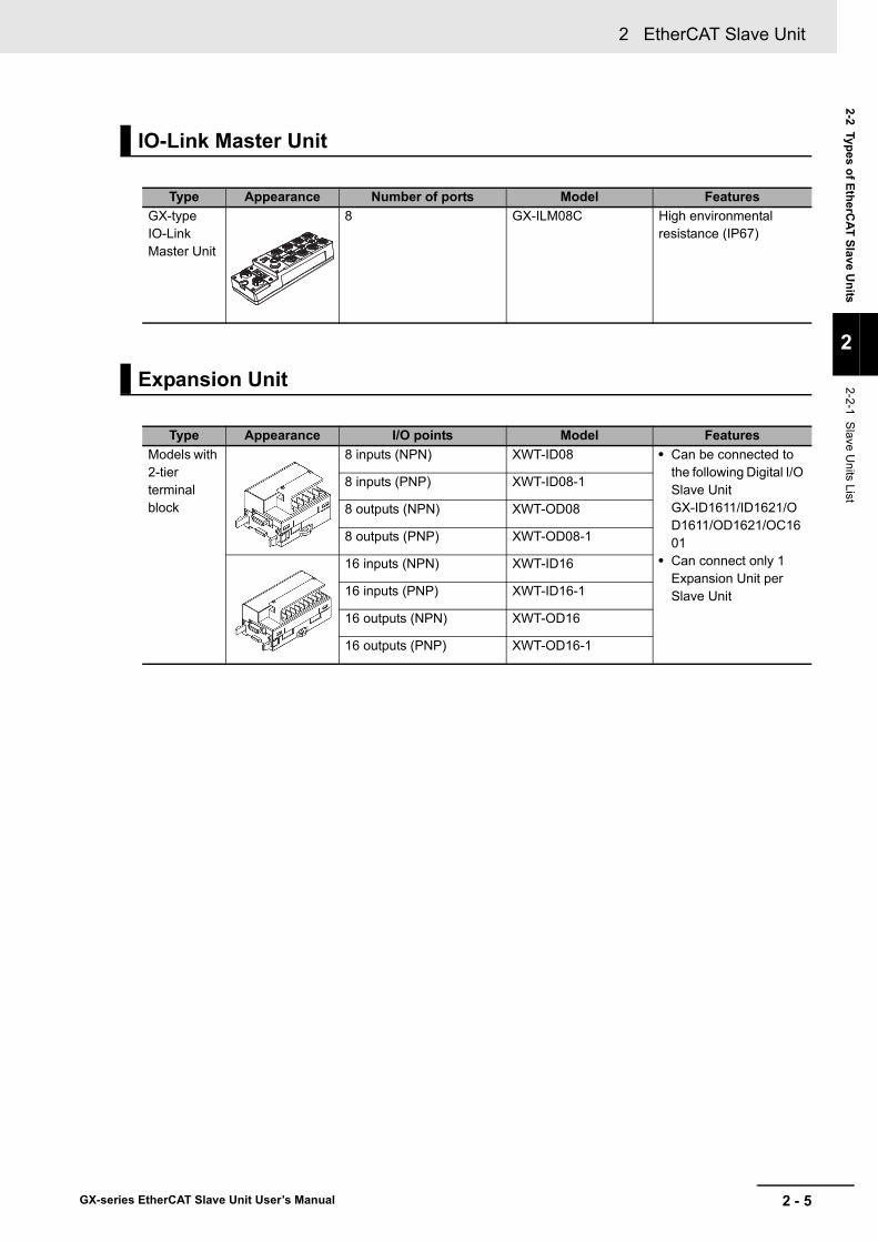
IO-Link Master Unit
Type Appearance Number of ports Model FeaturesGX-type IO-Link Master Unit
8 GX-ILM08C High environmental resistance (IP67)
Expansion Unit
Type Appearance I/O points Model FeaturesModels with 2-tier terminal block
8 inputs (NPN) XWT-ID08 • Can be connected to the following Digital I/O Slave Unit GX-ID1611/ID1621/OD1611/OD1621/OC1601
• Can connect only 1 Expansion Unit per Slave Unit
8 inputs (PNP) XWT-ID08-1
8 outputs (NPN) XWT-OD08
8 outputs (PNP) XWT-OD08-1
16 inputs (NPN) XWT-ID16
16 inputs (PNP) XWT-ID16-1
16 outputs (NPN) XWT-OD16
16 outputs (PNP) XWT-OD16-1
2 EtherCAT Slave Unit
2 - 6 GX-series EtherCAT Slave Unit User’s Manual
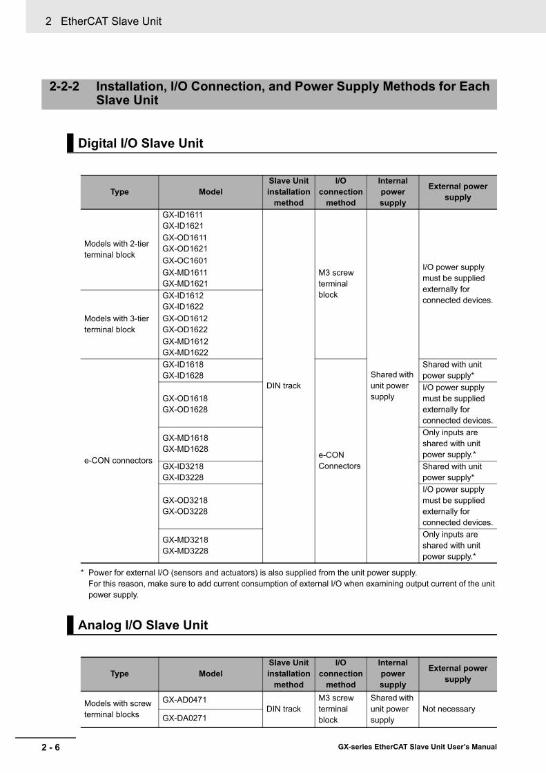
* Power for external I/O (sensors and actuators) is also supplied from the unit power supply. For this reason, make sure to add current consumption of external I/O when examining output current of the unit power supply.
2-2-2 Installation, I/O Connection, and Power Supply Methods for Each Slave Unit
Digital I/O Slave Unit
Type ModelSlave Unitinstallation
method
I/Oconnection
method
Internal power supply
External power supply
Models with 2-tier terminal block
GX-ID1611GX-ID1621
DIN track
M3 screwterminal block
Shared with unit power supply
I/O power supply must be supplied externally for connected devices.
GX-OD1611GX-OD1621GX-OC1601GX-MD1611GX-MD1621
Models with 3-tier terminal block
GX-ID1612GX-ID1622 GX-OD1612GX-OD1622GX-MD1612GX-MD1622
e-CON connectors
GX-ID1618GX-ID1628
e-CONConnectors
Shared with unit power supply*
GX-OD1618GX-OD1628
I/O power supply must be supplied externally for connected devices.
GX-MD1618GX-MD1628
Only inputs are shared with unit power supply.*
GX-ID3218GX-ID3228
Shared with unit power supply*
GX-OD3218GX-OD3228
I/O power supply must be supplied externally for connected devices.
GX-MD3218GX-MD3228
Only inputs are shared with unit power supply.*
Analog I/O Slave Unit
Type ModelSlave Unitinstallation
method
I/Oconnection
method
Internal power supply
External power supply
Models with screw terminal blocks
GX-AD0471DIN track
M3 screwterminal block
Shared with unit power supply
Not necessaryGX-DA0271

2 - 7
2 EtherCAT Slave Unit
GX-series EtherCAT Slave Unit User’s Manual
2-2 Types of EtherCAT Slave U
nits
2
2-2-2 Installation, I/O C
onnection, and Pow
er Supply
Methods for E
ach Slave U
nit
Encoder Input Slave Unit
Type ModelSlave Unitinstallation
method
I/Oconnection
method
Internal power supply
External power supply
Models with screw terminal blocks
GX-EC0211DIN track
M3 screwterminal block
Shared with unit power supply
I/O power supply must be supplied externally for connected devices.
GX-EC0241
IO-Link Master Unit
Type ModelSlave Unit installation
method
I/O connection
method
Internal power supply
External power supply
GX-type IO-Link Master Unit
GX-ILM08CScrew mounting
M12 Smartclick connectors
Shared with unit power supply
I/O power must be supplied externally for connected devices.
Expansion Unit
Type ModelSlave Unitinstallation
method
I/Oconnection
method
Internal power supply
External power supply
Models with 2-tier terminal block
XWT-ID08 (−1)
DIN trackM3 screwterminal block
Shared with unit power supply
Varies depending on the type of mounted Digital I/O Slave Unit(Refer to "11-1-2 I/O Power Supply" in Page 11 - 3.)
XWT-OD08 (−1)
XWT-ID16 (−1)
XWT-OD16 (−1)

2 EtherCAT Slave Unit
2 - 8 GX-series EtherCAT Slave Unit User’s Manual

3 - 1
3
GX-series EtherCAT Slave Unit User’s Manual
This chapter explains the procedure of using EtherCAT Slave Units based on specific setting examples.
3-1 Setup Examples and Basic Procedure . . . . . . . . . . . . . . . . . . . . . . . . . . . . . 3-23-1-1 System Setting Examples . . . . . . . . . . . . . . . . . . . . . . . . . . . . . . . . . . . . . . . . . 3-23-1-2 Basic Procedure . . . . . . . . . . . . . . . . . . . . . . . . . . . . . . . . . . . . . . . . . . . . . . . . 3-3
3-2 Setting and Wiring Hardware . . . . . . . . . . . . . . . . . . . . . . . . . . . . . . . . . . . . 3-43-2-1 Mounting and Setting EtherCAT Master Unit . . . . . . . . . . . . . . . . . . . . . . . . . . 3-43-2-2 Mounting and Setting Slave Units . . . . . . . . . . . . . . . . . . . . . . . . . . . . . . . . . . . 3-43-2-3 Wiring Communications Cables . . . . . . . . . . . . . . . . . . . . . . . . . . . . . . . . . . . . 3-43-2-4 Connecting Power Supplies . . . . . . . . . . . . . . . . . . . . . . . . . . . . . . . . . . . . . . . 3-43-2-5 Wiring I/O Devices . . . . . . . . . . . . . . . . . . . . . . . . . . . . . . . . . . . . . . . . . . . . . . 3-4
3-3 Starting Communications . . . . . . . . . . . . . . . . . . . . . . . . . . . . . . . . . . . . . . . 3-53-3-1 Starting a System . . . . . . . . . . . . . . . . . . . . . . . . . . . . . . . . . . . . . . . . . . . . . . . 3-53-3-2 Setting EtherCAT Communications . . . . . . . . . . . . . . . . . . . . . . . . . . . . . . . . . 3-53-3-3 Starting EtherCAT Communications . . . . . . . . . . . . . . . . . . . . . . . . . . . . . . . . . 3-5
3-4 Checking Operations . . . . . . . . . . . . . . . . . . . . . . . . . . . . . . . . . . . . . . . . . . . 3-63-4-1 Checking Unit Displays . . . . . . . . . . . . . . . . . . . . . . . . . . . . . . . . . . . . . . . . . . . 3-63-4-2 Confirming Data Read and Write . . . . . . . . . . . . . . . . . . . . . . . . . . . . . . . . . . . 3-63-4-3 Setting Slave Unit Parameter . . . . . . . . . . . . . . . . . . . . . . . . . . . . . . . . . . . . . . 3-6
Basic Usage Procedures

3 Basic Usage Procedures
3 - 2 GX-series EtherCAT Slave Unit User’s Manual
3-1 Setup Examples and Basic Procedure
This section explains the setup method by using simple system setting examples.
Connect each of the following Slave Units to the EtherCAT Master Unit and make the settings.
Although it is not shown in the figure above, supply the unit power and the I/O power separately.
3-1-1 System Setting Examples
Digital I/O Slave UnitGX-ID1611 (16 inputs) +Expansion UnitXWT-ID16 (16 inputs)
Set the node address to 1.
Digital I/O Slave UnitGX-OD1611 (16 outputs) +Expansion UnitXWT-OD16 (16 outputs)
Set the node address to 2.
Analog I/O Slave UnitGX-AD0471 (4 inputs)
Set the node address to 5.
Encoder Input Slave GX-EC0211 (2 inputs)
Set the node address to 6.
IO-Link Master UnitGX-ILM08C
Set the node address to 7.
EtherCAT Master Unit

3 - 3
3 Basic Usage Procedures
GX-series EtherCAT Slave Unit User’s Manual
3-1 Setup Examples and B
asic Procedure
3
3-1-2 Basic P
rocedure
Reference
The setting example explained here is the basic setting of GX-series EtherCAT Slave Units. If more detailed settings are required in actual operation, refer to the manual of the EtherCAT Master Unit or pages on this manual explaining the detail for each Slave Unit (Chapter 7 to Chapter 11). Moreover, if your system configuration includes Slave Units other than our products, make the setting upon referring to the manual of the relevant Slave Units.
This is the flow of the procedures explained in the following sections.
*1 If you use an IO-Link Master Unit, refer to the IO-Link System User’s Manual (W570) for IO-Link communications settingsand for information on starting IO-Link communications.
3-1-2 Basic Procedure
Start
Set
ting
and
Wiri
ng H
ardw
are
Sta
rting
Com
mun
icat
ions
Che
ckin
g O
pera
tions
Section 3-2-2
Section 3-2-3
Section 3-2-4
Section 3-2-5
Section 3-3-1
Section 3-3-3
Section 3-3-2
Section 3-2-1
Section 3-4-1
Section 3-4-2
End
Section 3-4-3
Mounting and Setting Slave Units
Wiring Communications Cables
Wiring I/O Devices
Starting a System
Starting EtherCAT Communications
Mounting and Setting EtherCAT Master Unit
Checking Unit Displays
Connecting Power Supplies
Setting an EtherCAT Communications
Confirming Data Read and Write
Setting Slave Unit Parameter
*1

3 Basic Usage Procedures
3 - 4 GX-series EtherCAT Slave Unit User’s Manual
3-2 Setting and Wiring Hardware
Make settings and wiring of the EtherCAT Master Unit and Slave Units, and power supply.
Mount the EtherCAT Master Unit at the prescribed location and make settings of Unit No. and so on. For the detailed explanation, refer to the manual of the EtherCAT Master Unit to be used.
Mount each Slave Unit at the prescribed location and make settings of node address and so on.For details, refer to each item below.
Mounting"4-1 Mounting Slave Units" in page 4 - 2
SettingPages in Chapter 6 to Chapter 11 which explain the general specification and details of each type of Slave Units.
Wire communications cables to the EtherCAT Master Unit and each Slave Unit. For wiring method, refer to "4-2 Connecting to EtherCAT Network" in page 4 - 4.
Connect the unit power supply to the EtherCAT Master Unit and Slave Units. In addition, connect the I/O power supply to each Slave Unit as required. For the connection method, refer to "4-3 Connecting to Unit Power Supply and I/O Power Supply" in page 4 - 8 or the wiring diagram of each Slave Unit (in pages explaining the details).
Connect input and output devices to each Slave Unit as required.For the connection method, refer to "4-4 Connecting an External Device" in page 4 - 13 or the wiring diagram of each Slave Unit (in pages explaining the details).
3-2-1 Mounting and Setting EtherCAT Master Unit
3-2-2 Mounting and Setting Slave Units
3-2-3 Wiring Communications Cables
3-2-4 Connecting Power Supplies
3-2-5 Wiring I/O Devices

3 - 5
3 Basic Usage Procedures
GX-series EtherCAT Slave Unit User’s Manual
3-3 Starting Com
munications
3
3-3-1 Starting a System
3-3 Starting Communications
Start the system, allocate I/O data of Slave Units, and then start the EtherCAT communications.For operational state and details of it, refer to "5-3 Communications State Transitions" in page 5 - 4.If you use an IO-Link Master Unit, refer to the IO-Link System User’s Manual (W570) for IO-Link communications settings and for information on starting IO-Link communications.
Turn ON the power supply to each Unit.
(1) Unit power supply of EtherCAT Master Units(2) Unit power supply of Slave Units (When the power is supplied, Slave Unit's [PWR] indicator is lit.)(3) I/O power supply of Slave Units
Note that there are no restrictions on the order of turning ON the power supplies.
The following communications are performed in EtherCAT.
PDO communications (remote I/O communications)Allocate I/O data of Slave Units to the EtherCAT Master Unit (PDO mapping) and perform PDO communication (remote I/O communications).For the detailed explanation of I/O data of each Slave Unit, refer to "I/O Data Allocation (PDO Mapping)” in Chapter 7 to Chapter 9. Note that the ESI file are used to allocate I/O data.For the detailed explanation of the procedure, refer to the manual of the EtherCAT Master Unit to be used and the manual of the Configuration Tool.
SDO communications (message communications)For the method of using, refer to the manual of the EtherCAT Master Unit to be used.Refer to "Appendix A - 1 Object Dictionary" for the detailed explanation of objects implemented on GX-series EtherCAT Slave Units. Note that the SDO communications can be used in the pre-operational state or more.
Shift to the operational state (EtherCAT communications possible) to start the EtherCAT communications.For how to shift to the operational state, refer to the manual of the EtherCAT Master Unit to be used.
3-3-1 Starting a System
3-3-2 Setting EtherCAT Communications
3-3-3 Starting EtherCAT Communications

3 Basic Usage Procedures
3 - 6 GX-series EtherCAT Slave Unit User’s Manual
3-4 Checking Operations
Confirm that the LED indicators of the EtherCAT Master Unit and Slave Units are normal status and that I/O data is correctly read and written. Moreover, make parameter settings for Slave Units as required.If you use an IO-Link Master Unit, refer to the IO-Link System User’s Manual (W570) for the method to confirm the operation of IO-Link communications.
EtherCAT Master UnitRefer to the manual of the EtherCAT Master Unit to be used.
EtherCAT Slave UnitsCheck that the status indicator of each Slave Unit is as follows.
Use the Configuration Tool to read IN data and OUT data of the EtherCAT Master Unit in order to check that the I/O data is correctly read and written.
Make parameter settings for each Slave Unit as required via the SDO communications.For the details of parameters that can be set, refer to the pages explaining details of each Slave Unit in Chapter 7 to Chapter 9.
3-4-1 Checking Unit Displays
LED StatePWR ONL/A IN FlickeringL/A OUT Flickering (turned OFF for the terminal Slave Unit only)RUN ONERR OFF
3-4-2 Confirming Data Read and Write
3-4-3 Setting Slave Unit Parameter

4 - 1
4
GX-series EtherCAT Slave Unit User’s Manual
This chapter explains the mounting and wiring methods of the EtherCAT Slave Unit.
4-1 Mounting Slave Units . . . . . . . . . . . . . . . . . . . . . . . . . . . . . . . . . . . . . . . . . . . 4-24-1-1 Mounting Preparation . . . . . . . . . . . . . . . . . . . . . . . . . . . . . . . . . . . . . . . . . . . . 4-24-1-2 Mounting Direction . . . . . . . . . . . . . . . . . . . . . . . . . . . . . . . . . . . . . . . . . . . . . . 4-24-1-3 Mounting Method . . . . . . . . . . . . . . . . . . . . . . . . . . . . . . . . . . . . . . . . . . . . . . . 4-24-1-4 Removal Method . . . . . . . . . . . . . . . . . . . . . . . . . . . . . . . . . . . . . . . . . . . . . . . . 4-3
4-2 Connecting to EtherCAT Network . . . . . . . . . . . . . . . . . . . . . . . . . . . . . . . . 4-44-2-1 Precautions for Network Connection . . . . . . . . . . . . . . . . . . . . . . . . . . . . . . . . 4-44-2-2 Preparation for Connecting Network . . . . . . . . . . . . . . . . . . . . . . . . . . . . . . . . . 4-54-2-3 Connecting Communications Cables and Connectors . . . . . . . . . . . . . . . . . . . 4-64-2-4 Connecting to Communications Cables . . . . . . . . . . . . . . . . . . . . . . . . . . . . . . 4-7
4-3 Connecting to Unit Power Supply and I/O Power Supply . . . . . . . . . . . . . 4-84-3-1 Precautions at Supplying Unit Power and I/O Power . . . . . . . . . . . . . . . . . . . . 4-84-3-2 Unit Power Supply Specifications . . . . . . . . . . . . . . . . . . . . . . . . . . . . . . . . . . . 4-94-3-3 Connecting the Unit Power Supply . . . . . . . . . . . . . . . . . . . . . . . . . . . . . . . . . . 4-94-3-4 Connecting the I/O Power Supply . . . . . . . . . . . . . . . . . . . . . . . . . . . . . . . . . . .4-11
4-4 Connecting an External Device . . . . . . . . . . . . . . . . . . . . . . . . . . . . . . . . . 4-134-4-1 Connecting to a Screw Terminal Block . . . . . . . . . . . . . . . . . . . . . . . . . . . . . . 4-134-4-2 Connecting to e-CON Connector Terminals . . . . . . . . . . . . . . . . . . . . . . . . . . 4-14
Installation and Wiring
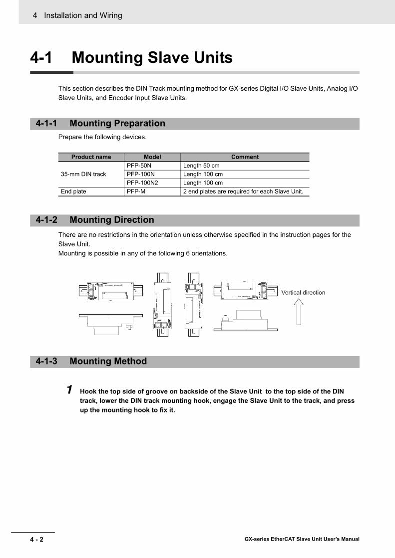
4 Installation and Wiring
4 - 2 GX-series EtherCAT Slave Unit User’s Manual
4-1 Mounting Slave Units
This section describes the DIN Track mounting method for GX-series Digital I/O Slave Units, Analog I/O Slave Units, and Encoder Input Slave Units.
Prepare the following devices.
There are no restrictions in the orientation unless otherwise specified in the instruction pages for the Slave Unit. Mounting is possible in any of the following 6 orientations.
1 Hook the top side of groove on backside of the Slave Unit to the top side of the DIN track, lower the DIN track mounting hook, engage the Slave Unit to the track, and press up the mounting hook to fix it.
4-1-1 Mounting Preparation
Product name Model Comment
35-mm DIN trackPFP-50N Length 50 cmPFP-100N Length 100 cmPFP-100N2 Length 100 cm
End plate PFP-M 2 end plates are required for each Slave Unit.
4-1-2 Mounting Direction
4-1-3 Mounting Method
Vertical direction

4 - 3
4 Installation and Wiring
GX-series EtherCAT Slave Unit User’s Manual
4-1 Mounting Slave U
nits
4
4-1-4 Rem
oval Method
2 Hook the bottom side of the end plate to the bottom side of the DIN track and then hook the top side. Attach an end plate on each side of the Unit.
Precautions for Safe Use
After the operation, make sure to check that the Slave Unit is securely mounted.
Loosen the screws on the end plate and remove the end plate from the DIN track. Then pull down the DIN track mounting hook to release the lock. Pull out the Slave Unit straight toward you.
4-1-4 Removal Method
DIN track
DIN track mounting hook
(2)
(1)
End plate
(2)
(1)

4 Installation and Wiring
4 - 4 GX-series EtherCAT Slave Unit User’s Manual
4-2 Connecting to EtherCAT Network
This section explains how to lay down EtherCAT network.
Observe the precautions below when laying down the EtherCAT network.
• When laying down an EtherCAT network, take sufficient safety measures and construct the network according to the standards. We recommend to request specialized constructors familiar with the safety measures and standards to perform the laying operation.
• Do not lay down EtherCAT network devices near any devices generating noise.If there is no choice but to lay them down in a noisy environment, make sure to take noise measures such as housing each device in metal cases.
• Check the following items for communications cables to be used.• Are there any disconnected cables?• Are any cables short-circuited?• Are there any problems in connector connections?
• To connect a cable to communications connector of each device, insert it securely until the connector of the communications cable is locked.
• Lay down and wire the communications cables separately from high-voltage electrical power lines.• Do not lay down the cables near devices generating noise.• Do not lay down the cables in high-temperature and high-humidity environment.• Use the cables in locations without powder dust and oil mist.• There is a limit to the bending radius of communications cables. Check the specification of
communications cables to be used for the information on bending radius.
4-2-1 Precautions for Network Connection
Precautions at laying down network
Precautions at laying down communications cables
4 - 5
4 Installation and Wiring
GX-series EtherCAT Slave Unit User’s Manual
4-2 Connecting to EtherC
AT Netw
ork
4
4-2-2 Preparation for C
onnecting Netw
ork
The following accessories are available for GX-series Digital I/O Slave Units, Analog I/O Slave Units, and Encoder Input Slave Units.
Refer to "6-3-3 Communications Connectors" in Page 6 - 8 for information on the communications cables for an IO-Link Master Unit.
Precautions for Correct Use
• The maximum cable length between connected nodes is 100 m. Note that some cables do notguarantee 100 m. In general, if the conductors are strand wire, the transmission performancewill be lower than solid wire and the operation at 100-m distance cannot be guaranteed.Confirm details with the cable manufacturer.
• When selecting connectors, check that the cables to be used conform to connectors. Items tobe checked include conductor size, conductor wire type (solid wire/twisted wire, 2/4 pairs), andouter diameter.
Reference
We recommend cables with double, aluminum tape and braided shielding, taking noise resistance into consideration.
4-2-2 Preparation for Connecting Network
Product name CommentTwisted-pair cable(Cables with connectors below are also allowed.)
100BASE-TX (Category 5 or higher)Double-shield (aluminum tape + braided shielding)
RJ45 connector Category 5 or higherShielded

4 Installation and Wiring
4 - 6 GX-series EtherCAT Slave Unit User’s Manual
Connect a communications cable and a connector by wiring them straight as shown below.
* Connect both ends of cable shielded wires to the connector hoods.
Reference
There are 2 types of wiring standards for Ethernet cables : "T568A" and "T568B."The figure above shows a wiring method conforming to the standard "T568A". The wiring method conforming to the standard "T568B" can also be used.
4-2-3 Connecting Communications Cables and Connectors
White-Green
Green
White-Orange
Blue
White-Blue
Orange
White-Brown
BrownConnector
hood
1
2
3
4
5
6
7
8
Shielded cable *
Wire colorPin No.
White-Green
Green
White-Orange
Blue
White-Blue
Orange
White-Brown
BrownConnector
hood
1
2
3
4
5
6
7
8
Shielded cable*
Wire color Pin No.

4 - 7
4 Installation and Wiring
GX-series EtherCAT Slave Unit User’s Manual
4-2 Connecting to EtherC
AT Netw
ork
4
4-2-4 Connecting to C
omm
unications Cables
EtherCAT networks allow free wiring in any connection forms. Connection before and after the GX-series EtherCAT Slave Units shall be made in daisy chain connection.
Connect the communications cable from the EtherCAT Master Unit to the [CN IN] connector of the Slave Units. Connect another the communications cable from the [CN OUT] connector of the first Slave Unit to the [CN IN] connector of the next Slave Unit.Note that nothing should be connected to the [CN OUT] connector of the Slave Unit at the terminal end of the network.
Precautions for Correct Use
• The cable length between each Slave Unit (L1, L2, ... Ln) must be within 100 m.• Connect cables securely until communications cable connectors click and are fixed in place.• When you wire the communications cables, observe their specifications (bending radius and
so on) defined by the cable manufacturer.
4-2-4 Connecting to Communications Cables
[CN IN] connector
[CN OUT] connector
EtherCAT Master Unit
Slave Unit
L1
L2
Ln
Communications cable
Do not connect anything.
Terminal Slave Unit
4 Installation and Wiring
4 - 8 GX-series EtherCAT Slave Unit User’s Manual
4-3 Connecting to Unit Power Supply and I/O Power Supply
The following power supplies are required to operate the EtherCAT network.
• Unit power supply: For communication and internal operation of Slave Units.• I/O power supply: For input/output operation of external I/O devices of each Slave Unit.
This section explains how to supply the unit power supply and I/O power supply.
When supplying the unit power supply and I/O power supply, take the followings into consideration for allowable current of cables and connectors, voltage drop, and layout of power supplies.
Consideration to cable voltage dropThe power supply voltage of a Slave Unit farthest to the power supply must be within the allowable variation range.
Supplying unit power supply and I/O power supply from multiple sourcesWhen the unit power and I/O power are supplied from multiple power supplies instead of from one power supply, the line current, voltage drop, and cable size can be reduced. Moreover, it is effective to secure safety of the system at power supply errors.
If power supply errors occurConsideration on layout and grouping of power supplies differ by whether you want to stop the entire system or not when a power supply error occurs.If you want to avoid stopping the entire system, we recommend to set power supplies at several locations and supply power to groups of Slave Units, or take similar measures.This has also the effects of reducing voltage drop and cable size and so on.
4-3-1 Precautions at Supplying Unit Power and I/O Power
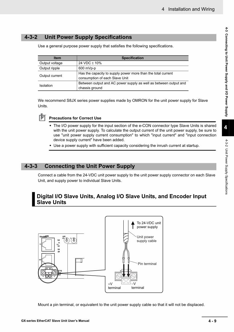
4 - 9
4 Installation and Wiring
GX-series EtherCAT Slave Unit User’s Manual
4-3 Connecting to U
nit Power Supply and I/O
Power Supply
4
4-3-2 Unit P
ower S
upply Specifications
Use a general purpose power supply that satisfies the following specifications.
We recommend S8JX series power supplies made by OMRON for the unit power supply for Slave Units.
Precautions for Correct Use
• The I/O power supply for the input section of the e-CON connector type Slave Units is sharedwith the unit power supply. To calculate the output current of the unit power supply, be sure touse "unit power supply current consumption" to which "input current" and "input connectiondevice supply current" have been added.
• Use a power supply with sufficient capacity considering the inrush current at startup.
Connect a cable from the 24-VDC unit power supply to the unit power supply connector on each Slave Unit, and supply power to individual Slave Units.
Mount a pin terminal, or equivalent to the unit power supply cable so that it will not be displaced.
4-3-2 Unit Power Supply Specifications
Item SpecificationOutput voltage 24 VDC ± 10%Output ripple 600 mVp-p
Output currentHas the capacity to supply power more than the total current consumption of each Slave Unit
IsolationBetween output and AC power supply as well as between output and chassis ground
4-3-3 Connecting the Unit Power Supply
Digital I/O Slave Units, Analog I/O Slave Units, and Encoder Input Slave Units
To 24-VDC unit power supply
+V terminal
−Vterminal
Unit power supply cable
Pin terminal

4 Installation and Wiring
4 - 10 GX-series EtherCAT Slave Unit User’s Manual
Recommended productThe following pin terminals are recommended for the unit power supply cables.
Also, the following screwdriver is recommended for removing pin terminals.
Supply the Unit power supply and the I/O power supply through the same power supply connector.(Notes) Supply the Unit power supply and the I/O power supply from separate sources.
An M12 connector (A-coding, male) is used for the power supply connector.
The Unit power supply specifications are given below.
Power Supply Connector
Model Applicable wire size Crimping tool Manufacturer
AI0,5-10WH 0.5 mm/AWG20
CRIMPFOX UD6 (Product No. 1204436)or CRIMPFOX ZA3series
Phoenix Contact Co., Ltd.
H0.5/16 orange 0.5 mm/AWG20Crimper PZ1.5 (Product No. 900599)
Weidmueller Japan Co., Ltd.
Model ManufacturerXW4Z-00C OMRON
IO-Link Master Unit
Item SpecificationUnit power supply voltage 20.4 to 26.4 VDC (24 VDC −15%/+10%)
Pin No. Signal Description1 UNT_P+ Unit power supply +2 UNT_P− Unit power supply −3 IO_P+ I/O power supply +4 IO_P− I/O power supply −
Power supply connector
GX-ILM08C

4 - 11
4 Installation and Wiring
GX-series EtherCAT Slave Unit User’s Manual
4-3 Connecting to U
nit Power Supply and I/O
Power Supply
4
4-3-4 Connecting the I/O
Power S
upply
Units with screw terminal blocksIt supplies the 24-VDC I/O power to the I/O power supply terminal on each Slave Unit.For the locations of I/O power supply terminals, see the terminal layout diagrams for each Slave Unit or wiring diagrams in Chapter 7 to Chapter 10.Moreover, for how to connect power supplies to terminals, refer to "4-4-1 Connecting to a Screw Terminal Block" in Page 4 - 13.
Units with e-CON connectorsThe following e-CON connector type Slave Units (Output Slave Units and output sections of Input/Output Slave Units) are equipped with I/O power supply connectors to supply I/O power to external devices.
• GX-OD1618/OD1628/MD1618 (output section only)/MD1628 (output section only)• GX-OD3218/OD3228/MD3218 (output section only)/MD3228 (output section only)
To connect external devices to these Slave Units, supply the 24-VDC I/O power to the I/O power supply connector.
Mount a pin terminal, or equivalent to the power supply cable so that it will not be displaced.
4-3-4 Connecting the I/O Power Supply
Digital I/O Slave Units, Analog I/O Slave Units, and Encoder Input Slave Units
V terminal
G terminal
24-VDC power supply
+
−

4 Installation and Wiring
4 - 12 GX-series EtherCAT Slave Unit User’s Manual
Recommended productThe following pin terminals are recommended for the unit power supply cables.
Also, the following screwdriver is recommended for removing pin terminals.
Supply the Unit power supply and the I/O power supply through the same power supply connector.(Notes) Supply the Unit power supply and the I/O power supply from separate sources.An M12 connector (A-coding, male) is used for the power supply connector.
The I/O power supply specifications are given below.
Power Supply Connector
Model Applicable wire size Crimping tool Manufacturer
AI0,5-10WH 0.5 mm/AWG20
CRIMPFOX UD6 (Product No. 1204436)or CRIMPFOX ZA3series
Phoenix Contact Co., Ltd.
H0.5/16 orange 0.5 mm/AWG20Crimper PZ1.5 (Product No. 900599)
Weidmueller Japan Co., Ltd.
Model ManufacturerXW4Z-00C OMRON
IO-Link Master Unit
Item SpecificationI/O power supply 20.4 to 26.4 VDC (24 VDC −15%/+10%)
Pin No. Signal Description1 UNT_P+ Unit power supply +2 UNT_P− Unit power supply −3 IO_P+ I/O power supply +4 IO_P− I/O power supply −
Power supply connector
GX-ILM08C
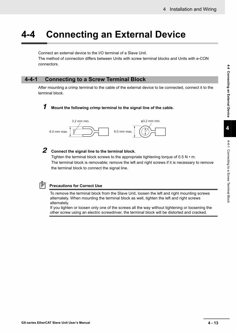
4 - 13
4 Installation and Wiring
GX-series EtherCAT Slave Unit User’s Manual
4-4 Connecting an External D
evice
4
4-4-1 Connecting to a S
crew Term
inal Block
4-4 Connecting an External Device
Connect an external device to the I/O terminal of a Slave Unit.The method of connection differs between Units with screw terminal blocks and Units with e-CON connectors.
After mounting a crimp terminal to the cable of the external device to be connected, connect it to the terminal block.
1 Mount the following crimp terminal to the signal line of the cable.
2 Connect the signal line to the terminal block.Tighten the terminal block screws to the appropriate tightening torque of 0.5 N • m.The terminal block is removable; remove the left and right screws if it is necessary to remove the terminal block to connect the signal line.
Precautions for Correct Use
To remove the terminal block from the Slave Unit, loosen the left and right mounting screws alternately. When mounting the terminal block as well, tighten the left and right screws alternately.If you tighten or loosen only one of the screws all the way without tightening or loosening the other screw using an electric screwdriver, the terminal block will be distorted and cracked.
4-4-1 Connecting to a Screw Terminal Block
6.0 mm max. 6.0 mm max.
φ3.2 mm min.3.2 mm min.
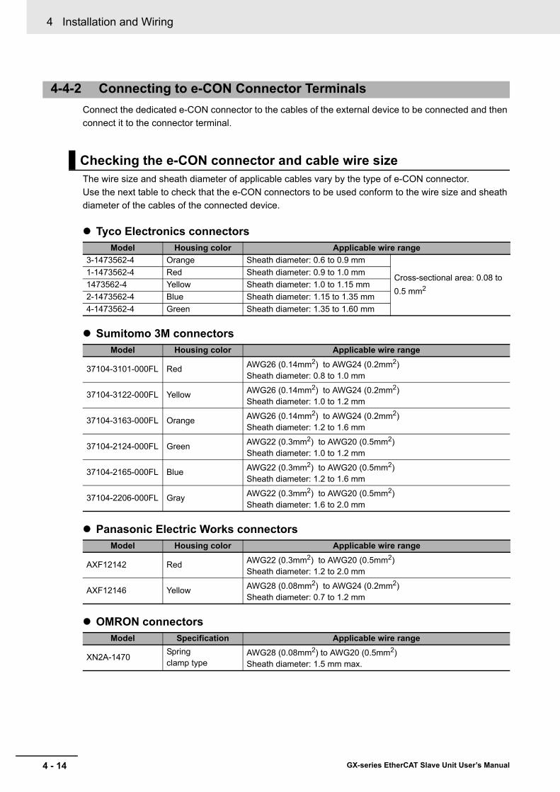
4 Installation and Wiring
4 - 14 GX-series EtherCAT Slave Unit User’s Manual
Connect the dedicated e-CON connector to the cables of the external device to be connected and then connect it to the connector terminal.
The wire size and sheath diameter of applicable cables vary by the type of e-CON connector.Use the next table to check that the e-CON connectors to be used conform to the wire size and sheath diameter of the cables of the connected device.
Tyco Electronics connectors
Sumitomo 3M connectors
Panasonic Electric Works connectors
OMRON connectors
4-4-2 Connecting to e-CON Connector Terminals
Checking the e-CON connector and cable wire size
Model Housing color Applicable wire range3-1473562-4 Orange Sheath diameter: 0.6 to 0.9 mm
Cross-sectional area: 0.08 to 0.5 mm2
1-1473562-4 Red Sheath diameter: 0.9 to 1.0 mm1473562-4 Yellow Sheath diameter: 1.0 to 1.15 mm2-1473562-4 Blue Sheath diameter: 1.15 to 1.35 mm4-1473562-4 Green Sheath diameter: 1.35 to 1.60 mm
Model Housing color Applicable wire range
37104-3101-000FL Red AWG26 (0.14mm2) to AWG24 (0.2mm2) Sheath diameter: 0.8 to 1.0 mm
37104-3122-000FL Yellow AWG26 (0.14mm2) to AWG24 (0.2mm2) Sheath diameter: 1.0 to 1.2 mm
37104-3163-000FL Orange AWG26 (0.14mm2) to AWG24 (0.2mm2) Sheath diameter: 1.2 to 1.6 mm
37104-2124-000FL Green AWG22 (0.3mm2) to AWG20 (0.5mm2) Sheath diameter: 1.0 to 1.2 mm
37104-2165-000FL Blue AWG22 (0.3mm2) to AWG20 (0.5mm2) Sheath diameter: 1.2 to 1.6 mm
37104-2206-000FL Gray AWG22 (0.3mm2) to AWG20 (0.5mm2) Sheath diameter: 1.6 to 2.0 mm
Model Housing color Applicable wire range
AXF12142 Red AWG22 (0.3mm2) to AWG20 (0.5mm2) Sheath diameter: 1.2 to 2.0 mm
AXF12146 Yellow AWG28 (0.08mm2) to AWG24 (0.2mm2) Sheath diameter: 0.7 to 1.2 mm
Model Specification Applicable wire range
XN2A-1470Springclamp type
AWG28 (0.08mm2) to AWG20 (0.5mm2) Sheath diameter: 1.5 mm max.

4 - 15
4 Installation and Wiring
GX-series EtherCAT Slave Unit User’s Manual
4-4 Connecting an External D
evice
4
4-4-2 Connecting to e-C
ON
Connector Term
inals
Using Tyco Electronics, Sumitomo 3M or Panasonic Electric Works connectorsCables of connected devices are normally cut in semi-strip or strip specification as shown in the next figures.
When the cables are prepared this way, an e-CON connector cannot be attached. First cut the end and remove the cable sheath as shown in the following diagram. (Do not strip the sheaths of the core wires.)
Using OMRON connectorsAlign the cable with the STRIP GAUGE described on the side of the connector. Remove 7 to 8 mm of the wiring sheath, and twist the exposed wires several times.
Processing external devices cables
Semi-strip specification Strip specification
20 mm min.
Core wires Strip sheaths of core wires
7 to 8 mm

4 Installation and Wiring
4 - 16 GX-series EtherCAT Slave Unit User’s Manual
Insert the cable wire of the extend device to the cable connector.Make sure that the terminal numbers printed on the connector cover matches the colors of wires as shown in the next table.
Notes Wire colors have been changed according to revisions in the JIS standards for photoelectric sensors and proximity sensors.The colors in parentheses are the wire colors prior to the revisions.
Using Tyco Electronics, Sumitomo 3M or Panasonic Electric Works connectors
1 Insert the wire all the way to the wire insertion opening on the cover of the cable connector.
2 Use a pliers, or equivalent to press the cover into the body. At this point, press the cover straight in such that the cover is horizontal to the body.
Using OMRON connectors
1 Use a flat-blade screwdriver to push the operation lever inside the connector's operation opening until it locks, as shown in the following diagram.
Inserting wires into the cable connector
Terminal number
NPN Slave Unit PNP Slave Unit3-wire sensor 2-wire sensor 3-wire sensor 2-wire sensor
1 Brown (red) − Brown (red) Brown (white)2 − − − −3 Blue (black) Blue (black) Blue (black) −4 Black (white) Brown (white) Black (white) Blue (black)
Flat-bladeScrewdriver
Operation opening

4 - 17
4 Installation and Wiring
GX-series EtherCAT Slave Unit User’s Manual
4-4 Connecting an External D
evice
4
4-4-3 Connecting the M
12 Connector
2 Insert the wire all the way to the back of the wire insertion opening.Check that the sheath of the wire is inserted into the wire insertion opening, and that the end of the conductor has passed through the connection part.
3 Insert a screwdriver into the reset opening and pull back the operation lever lightly.A click will be heard and the operation lever will return to its normal position.
4 Lightly pull the wire to confirm that it is connected properly.
Precautions for Correct Use
To remove a wire, push in the operation lever, check that the operation lever has locked, and then pull out the wire. Also, after removing the wire, always return the operation lever to its normal position.
For SmartClick Connectors, insert the Connector all the way and turn it approx. 1/8 of a turn. Torque management is not required.For screw connections to M12 connectors, tighten the lock on the M12 connection sufficiently with your hands (tightening torque: 0.39 to 0.49 N·m).If the lock is not tightened sufficiently, the degree of protection may not be achieved and the connector may become loose due to vibration. Never use pliers or other tools to tighten the lock. Doing so may damage the connector.
4-4-3 Connecting the M12 Connector
Wire insertion openingWire sheath partConnection part
Reset openingOperation lever (white)

4 Installation and Wiring
4 - 18 GX-series EtherCAT Slave Unit User’s Manual
5 - 1
5
GX-series EtherCAT Slave Unit User’s Manual
This chapter explains the overview of EtherCAT communications.
5-1 Structure of CAN application protocol over EtherCAT (CoE) . . . . . . . . . . 5-25-2 EtherCAT Slave Information File (ESI File) . . . . . . . . . . . . . . . . . . . . . . . . . 5-35-3 Communications State Transitions . . . . . . . . . . . . . . . . . . . . . . . . . . . . . . . 5-45-4 Process Data Objects (PDO) . . . . . . . . . . . . . . . . . . . . . . . . . . . . . . . . . . . . . 5-5
5-4-1 Overview . . . . . . . . . . . . . . . . . . . . . . . . . . . . . . . . . . . . . . . . . . . . . . . . . . . . . . 5-55-4-2 PDO Mapping Settings . . . . . . . . . . . . . . . . . . . . . . . . . . . . . . . . . . . . . . . . . . . 5-55-4-3 Sync Manager PDO Assignment Settings . . . . . . . . . . . . . . . . . . . . . . . . . . . . 5-65-4-4 Fixed PDO Mapping . . . . . . . . . . . . . . . . . . . . . . . . . . . . . . . . . . . . . . . . . . . . . 5-7
5-5 Service Data Object (SDO) . . . . . . . . . . . . . . . . . . . . . . . . . . . . . . . . . . . . . 5-105-5-1 Overview . . . . . . . . . . . . . . . . . . . . . . . . . . . . . . . . . . . . . . . . . . . . . . . . . . . . . 5-105-5-2 Abort Codes . . . . . . . . . . . . . . . . . . . . . . . . . . . . . . . . . . . . . . . . . . . . . . . . . . 5-10
5-6 EtherCAT Master Unit - Slave Unit Communications . . . . . . . . . . . . . . . . 5-115-6-1 FREE RUN Mode . . . . . . . . . . . . . . . . . . . . . . . . . . . . . . . . . . . . . . . . . . . . . . .5-11
5-7 Emergency Messages . . . . . . . . . . . . . . . . . . . . . . . . . . . . . . . . . . . . . . . . . 5-135-7-1 Emergency Message Notification . . . . . . . . . . . . . . . . . . . . . . . . . . . . . . . . . . 5-135-7-2 Diagnosis History . . . . . . . . . . . . . . . . . . . . . . . . . . . . . . . . . . . . . . . . . . . . . . 5-14
5-8 Sysmac Device Functions . . . . . . . . . . . . . . . . . . . . . . . . . . . . . . . . . . . . . . 5-15
EtherCAT Communications
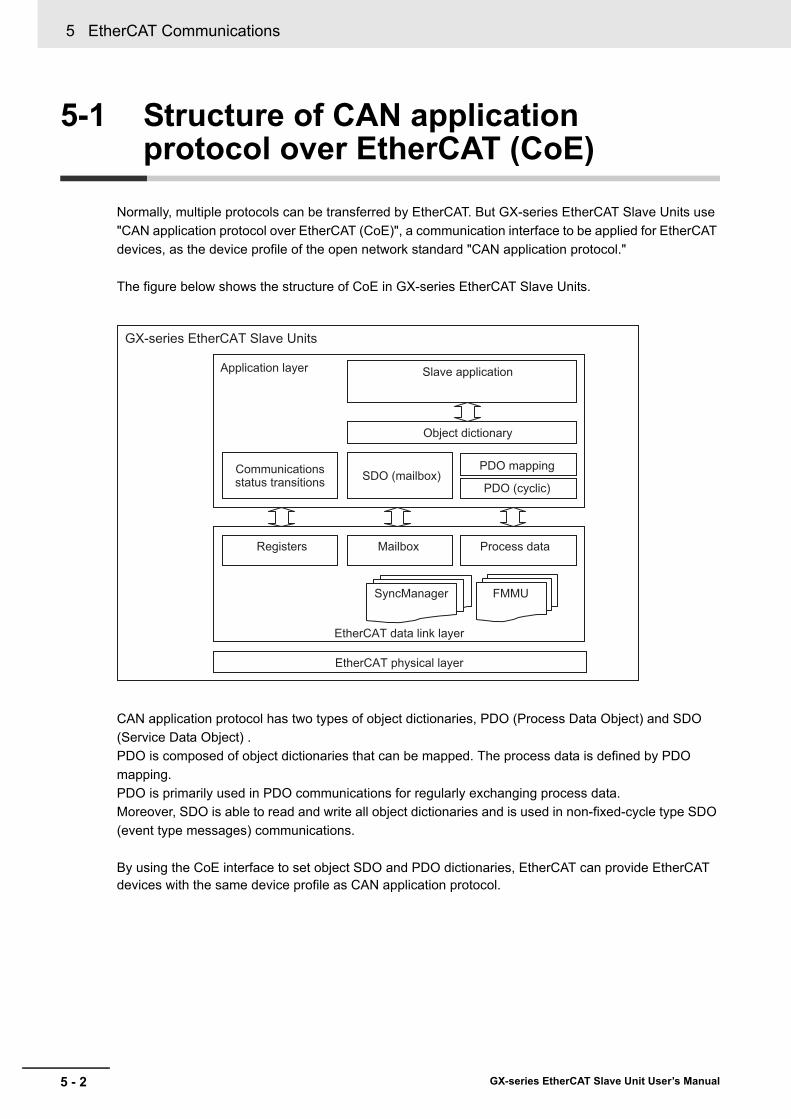
5 EtherCAT Communications
5 - 2 GX-series EtherCAT Slave Unit User’s Manual
5-1 Structure of CAN application protocol over EtherCAT (CoE)
Normally, multiple protocols can be transferred by EtherCAT. But GX-series EtherCAT Slave Units use "CAN application protocol over EtherCAT (CoE)", a communication interface to be applied for EtherCAT devices, as the device profile of the open network standard "CAN application protocol."
The figure below shows the structure of CoE in GX-series EtherCAT Slave Units.
CAN application protocol has two types of object dictionaries, PDO (Process Data Object) and SDO (Service Data Object) .PDO is composed of object dictionaries that can be mapped. The process data is defined by PDO mapping.PDO is primarily used in PDO communications for regularly exchanging process data.Moreover, SDO is able to read and write all object dictionaries and is used in non-fixed-cycle type SDO (event type messages) communications.
By using the CoE interface to set object SDO and PDO dictionaries, EtherCAT can provide EtherCAT devices with the same device profile as CAN application protocol.
GX-series EtherCAT Slave Units
EtherCAT physical layer
Communicationsstatus transitions SDO (mailbox)
Slave application
Object dictionary
PDO mapping
PDO (cyclic)
EtherCAT data link layer
Registers Mailbox Process data
FMMUSyncManager
Application layer
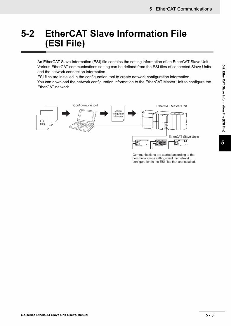
5 - 3
5 EtherCAT Communications
GX-series EtherCAT Slave Unit User’s Manual
5-2 EtherCAT Slave Inform
ation File (ESI File)
5
5-2 EtherCAT Slave Information File (ESI File)
An EtherCAT Slave Information (ESI) file contains the setting information of an EtherCAT Slave Unit. Various EtherCAT communications setting can be defined from the ESI files of connected Slave Units and the network connection information. ESI files are installed in the configuration tool to create network configuration information.You can download the network configuration information to the EtherCAT Master Unit to configure the EtherCAT network.
ESI files
Network configuration information
EtherCAT Master Unit
EtherCAT Slave Units
Configuration tool
Communications are started according to the communications settings and the network configuration in the ESI files that are installed.
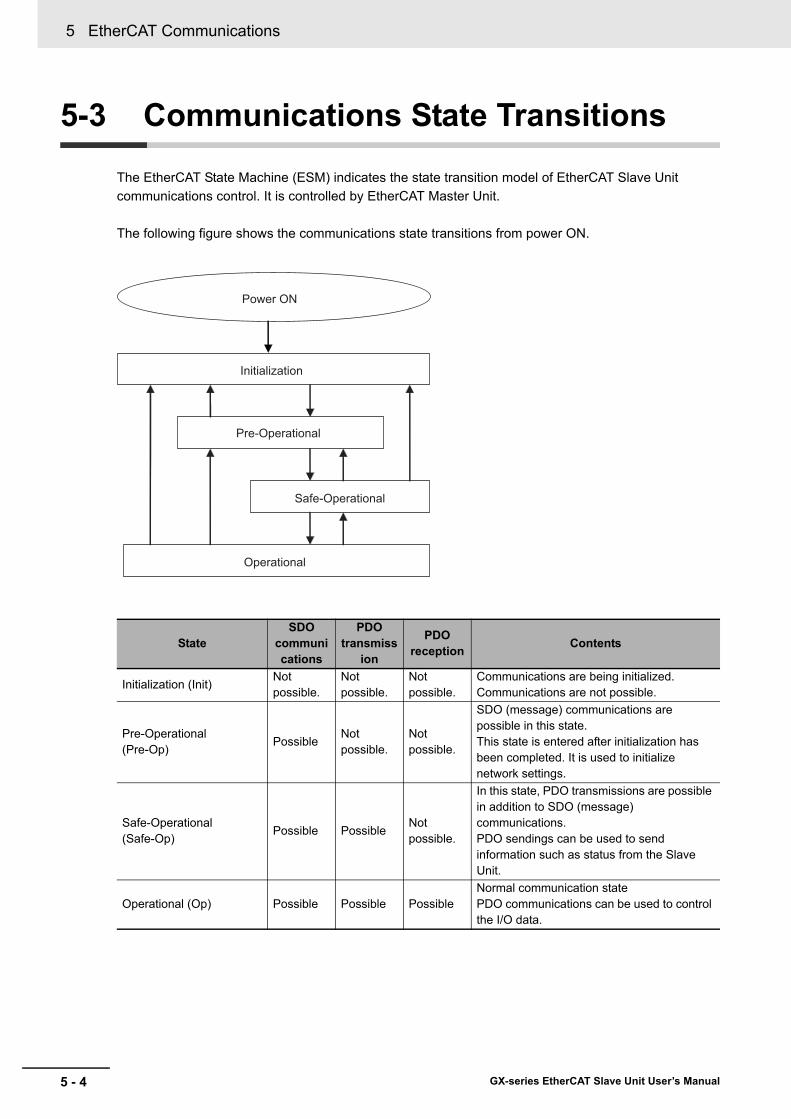
5 EtherCAT Communications
5 - 4 GX-series EtherCAT Slave Unit User’s Manual
5-3 Communications State Transitions
The EtherCAT State Machine (ESM) indicates the state transition model of EtherCAT Slave Unit communications control. It is controlled by EtherCAT Master Unit.
The following figure shows the communications state transitions from power ON.
StateSDO
communications
PDO transmiss
ion
PDO reception Contents
Initialization (Init)Not possible.
Not possible.
Not possible.
Communications are being initialized. Communications are not possible.
Pre-Operational(Pre-Op)
PossibleNot possible.
Not possible.
SDO (message) communications are possible in this state. This state is entered after initialization has been completed. It is used to initialize network settings.
Safe-Operational(Safe-Op)
Possible PossibleNot possible.
In this state, PDO transmissions are possible in addition to SDO (message) communications. PDO sendings can be used to send information such as status from the Slave Unit.
Operational (Op) Possible Possible PossibleNormal communication statePDO communications can be used to control the I/O data.
Initialization
Pre-Operational
Safe-Operational
Operational
Power ON

5 - 5
5 EtherCAT Communications
GX-series EtherCAT Slave Unit User’s Manual
5-4 Process Data O
bjects (PDO
)
5
5-4-1 Overview
5-4 Process Data Objects (PDO)
The process data objects (PDO) are used for real-time data transfer via cyclic communications.There are two types in PDO: RxPDO that receives data from the EtherCAT Master Unit and TxPDO that sends the present value from a EtherCAT Slave Unit to the EtherCAT Master Unit.
It is possible to hold multiple objects in the EtherCAT application layer so that various process data of EtherCAT Slave Units can be transferred. The details of process data are described in PDO Mapping Objects and Sync Manager PDO Assignment Objects. GX-series EtherCAT Slave Units support PDO mapping for I/O control.
The PDO mapping indicates the mapping for application objects (realtime process data) between the object dictionary and PDO.The number of mapped objects is described in sub-index 0 of the mapping table. In this mapping table, indexes 1600 hex to 17FF hex are used for RxPDO and 1A00 hex to 1BFF hex are used for TxPDO.
5-4-1 Overview
5-4-2 PDO Mapping Settings
RxPDOoutput data, operation command, and so on
TxPDOinput data, status, and so on
EtherCATMaster
Unit
EtherCATSlaveUnit

5 EtherCAT Communications
5 - 6 GX-series EtherCAT Slave Unit User’s Manual
The figure below shows an example of PDO mapping.
A sync manager channel consists of several PDOs. The sync manager PDO assignment objects describe how these PDOs are related to the Sync Manager. The number of PDOs is given in sub-index 0 of the sync manager PDO assignment table. In this table, index 1C12 hex is for RxPDOs and 1C13 hex is for TxPDOs.
The figure below shows an example of sync manager PDO mapping.
5-4-3 Sync Manager PDO Assignment Settings
1ZZZ hex1ZZZ hex
1ZZZ hex
6TTT hex
6UUU hex6VVV hex
6YYY hex
6ZZZ hex
02 hex03 hex
01 hex
TT hex
UU hexVV hex
YY hex
ZZ hex
6UUU hex UU hex
6TTT hex TT hex
6YYY hex YY hex
816
8
Object BObject C
Object A
Object E
Object D
Object A Object B Object D
PDO-Length : 32 BitPDO_1
Index Sub Object contents
Map
ping
obj
ects
App
licat
ion
obje
cts
Object dictionary
1C1Z hex1C1Z hex
1C1Z hex
23
1
PDO BPDO C
PDO A
PDO E
PDO D
PDO A PDO B PDO D
Index Sub Object contents
Syn
c m
anag
er P
DO
assi
gnm
ent o
bjec
ts M
appi
ng o
bjec
ts
1A00 hex
1A01 hex1A02 hex
1A03 hex
1A04 hex
PDO GPDO F1A05 hex
1A06 hex
1A00 hex
1A01 hex1A03 hex
Sync manager entity Z
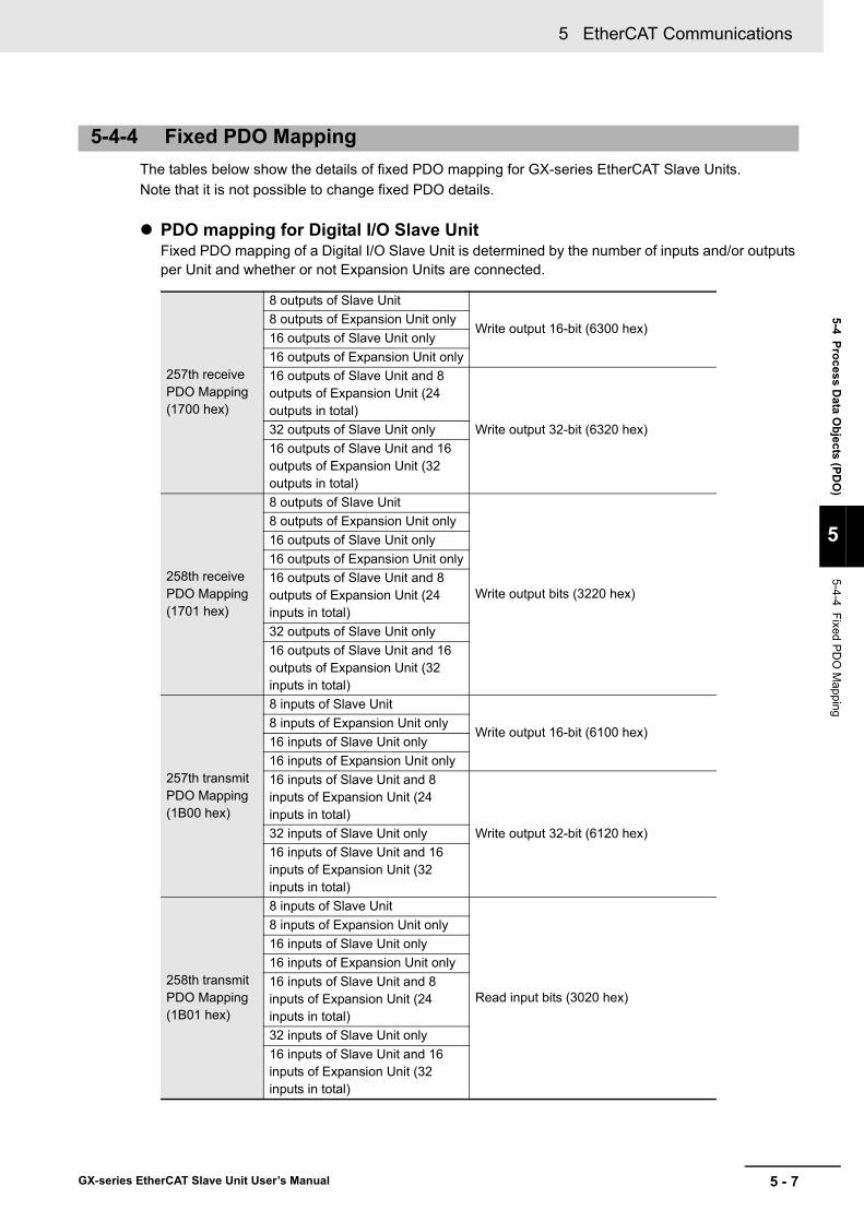
5 - 7
5 EtherCAT Communications
GX-series EtherCAT Slave Unit User’s Manual
5-4 Process Data O
bjects (PDO
)
5
5-4-4 Fixed PD
O M
apping
The tables below show the details of fixed PDO mapping for GX-series EtherCAT Slave Units.Note that it is not possible to change fixed PDO details.
PDO mapping for Digital I/O Slave UnitFixed PDO mapping of a Digital I/O Slave Unit is determined by the number of inputs and/or outputs per Unit and whether or not Expansion Units are connected.
5-4-4 Fixed PDO Mapping
257th receive PDO Mapping (1700 hex)
8 outputs of Slave Unit
Write output 16-bit (6300 hex)8 outputs of Expansion Unit only16 outputs of Slave Unit only16 outputs of Expansion Unit only16 outputs of Slave Unit and 8 outputs of Expansion Unit (24 outputs in total)
Write output 32-bit (6320 hex)32 outputs of Slave Unit only16 outputs of Slave Unit and 16 outputs of Expansion Unit (32 outputs in total)
258th receive PDO Mapping (1701 hex)
8 outputs of Slave Unit
Write output bits (3220 hex)
8 outputs of Expansion Unit only16 outputs of Slave Unit only16 outputs of Expansion Unit only16 outputs of Slave Unit and 8 outputs of Expansion Unit (24 inputs in total)32 outputs of Slave Unit only16 outputs of Slave Unit and 16 outputs of Expansion Unit (32 inputs in total)
257th transmit PDO Mapping (1B00 hex)
8 inputs of Slave Unit
Write output 16-bit (6100 hex)8 inputs of Expansion Unit only16 inputs of Slave Unit only16 inputs of Expansion Unit only16 inputs of Slave Unit and 8 inputs of Expansion Unit (24 inputs in total)
Write output 32-bit (6120 hex)32 inputs of Slave Unit only16 inputs of Slave Unit and 16 inputs of Expansion Unit (32 inputs in total)
258th transmit PDO Mapping (1B01 hex)
8 inputs of Slave Unit
Read input bits (3020 hex)
8 inputs of Expansion Unit only16 inputs of Slave Unit only16 inputs of Expansion Unit only16 inputs of Slave Unit and 8 inputs of Expansion Unit (24 inputs in total)32 inputs of Slave Unit only16 inputs of Slave Unit and 16 inputs of Expansion Unit (32 inputs in total)
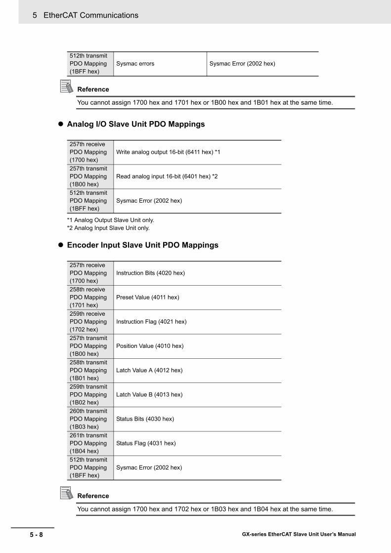
5 EtherCAT Communications
5 - 8 GX-series EtherCAT Slave Unit User’s Manual
Reference
You cannot assign 1700 hex and 1701 hex or 1B00 hex and 1B01 hex at the same time.
Analog I/O Slave Unit PDO Mappings
*1 Analog Output Slave Unit only.*2 Analog Input Slave Unit only.
Encoder Input Slave Unit PDO Mappings
Reference
You cannot assign 1700 hex and 1702 hex or 1B03 hex and 1B04 hex at the same time.
512th transmit PDO Mapping (1BFF hex)
Sysmac errors Sysmac Error (2002 hex)
257th receive PDO Mapping (1700 hex)
Write analog output 16-bit (6411 hex) *1
257th transmit PDO Mapping (1B00 hex)
Read analog input 16-bit (6401 hex) *2
512th transmit PDO Mapping (1BFF hex)
Sysmac Error (2002 hex)
257th receive PDO Mapping (1700 hex)
Instruction Bits (4020 hex)
258th receive PDO Mapping (1701 hex)
Preset Value (4011 hex)
259th receive PDO Mapping (1702 hex)
Instruction Flag (4021 hex)
257th transmit PDO Mapping (1B00 hex)
Position Value (4010 hex)
258th transmit PDO Mapping (1B01 hex)
Latch Value A (4012 hex)
259th transmit PDO Mapping (1B02 hex)
Latch Value B (4013 hex)
260th transmit PDO Mapping (1B03 hex)
Status Bits (4030 hex)
261th transmit PDO Mapping (1B04 hex)
Status Flag (4031 hex)
512th transmit PDO Mapping (1BFF hex)
Sysmac Error (2002 hex)

5 - 9
5 EtherCAT Communications
GX-series EtherCAT Slave Unit User’s Manual
5-4 Process Data O
bjects (PDO
)
5
5-4-4 Fixed PD
O M
apping
IO-Link Master Unit
1st receive PDO Mapping (1600 hex)
Port1 Output Data (7000 hex)
2nd receive PDO Mapping (1601 hex)
Port2 Output Data (7010 hex)
3rd receive PDO Mapping (1602 hex)
Port3 Output Data (7020 hex)
4th receive PDO Mapping (1603 hex)
Port4 Output Data (7030 hex)
5th receive PDO Mapping (1604 hex)
Port5 Output Data (7040 hex)
6th receive PDO Mapping (1605 hex)
Port6 Output Data (7050 hex)
7th receive PDO Mapping (1606 hex)
Port7 Output Data (7060 hex)
8th receive PDO Mapping (1607 hex)
Port8 Output Data (7070 hex)
257th receive PDO Mapping (1700 hex)
Digital Output Data (3100 hex)
1st transmit PDO Mapping (1A00 hex)
Port1 Input Data (6000 hex)
2nd transmit PDO Mapping (1A01 hex)
Port2 Input Data (6010 hex)
3rd transmit PDO Mapping (1A02 hex)
Port3 Input Data (6020 hex)
4th transmit PDO Mapping (1A03 hex)
Port4 Input Data (6030 hex)
5th transmit PDO Mapping (1A04 hex)
Port5 Input Data (6040H hex)
6th transmit PDO Mapping (1A05 hex)
Port6 Input Data (6050 hex)
7th transmit PDO Mapping (1A06 hex)
Port7 Input Data (6060 hex)
8th transmit PDO Mapping (1A07 hex)
Port8 Input Data (6070 hex)
257th transmit PDO Mapping (1B00 hex)
I/O Port Status (3000 hex)
258th transmit PDO Mapping (1B01 hex)
Port1_2 I/O Port Error Status (3001 hex)
259th transmit PDO Mapping (1B02 hex)
Port3_4 I/O Port Error Status (3002 hex)
260th transmit PDO Mapping (1B03 hex)
Port5_6 I/O Port Error Status (3003 hex)
261th transmit PDO Mapping (1B04 hex)
Port7_8 I/O Port Error Status (3004 hex)
262th transmit PDO Mapping (1B05 hex)
Digital Input Data (3005 hex)
511th transmit PDO Mapping (1BFE hex)
Diagnosis History (10F3 hex)
512th transmit PDO Mapping (1BFF hex)
Sysmac Error Status (2002 hex)
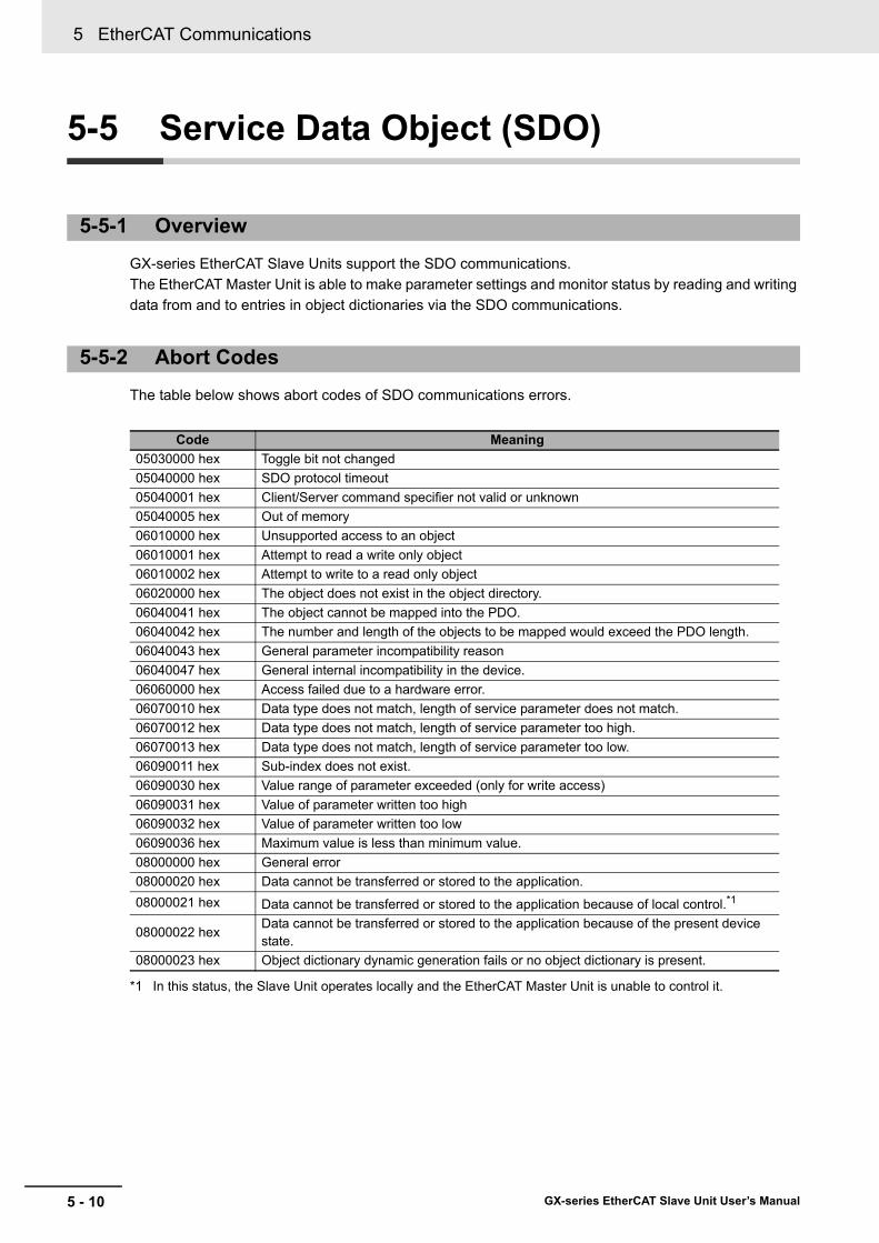
5 EtherCAT Communications
5 - 10 GX-series EtherCAT Slave Unit User’s Manual
5-5 Service Data Object (SDO)
GX-series EtherCAT Slave Units support the SDO communications.The EtherCAT Master Unit is able to make parameter settings and monitor status by reading and writing data from and to entries in object dictionaries via the SDO communications.
The table below shows abort codes of SDO communications errors.
*1 In this status, the Slave Unit operates locally and the EtherCAT Master Unit is unable to control it.
5-5-1 Overview
5-5-2 Abort Codes
Code Meaning05030000 hex Toggle bit not changed05040000 hex SDO protocol timeout05040001 hex Client/Server command specifier not valid or unknown05040005 hex Out of memory06010000 hex Unsupported access to an object06010001 hex Attempt to read a write only object06010002 hex Attempt to write to a read only object06020000 hex The object does not exist in the object directory.06040041 hex The object cannot be mapped into the PDO. 06040042 hex The number and length of the objects to be mapped would exceed the PDO length. 06040043 hex General parameter incompatibility reason06040047 hex General internal incompatibility in the device.06060000 hex Access failed due to a hardware error.06070010 hex Data type does not match, length of service parameter does not match.06070012 hex Data type does not match, length of service parameter too high.06070013 hex Data type does not match, length of service parameter too low.06090011 hex Sub-index does not exist.06090030 hex Value range of parameter exceeded (only for write access)06090031 hex Value of parameter written too high06090032 hex Value of parameter written too low06090036 hex Maximum value is less than minimum value.08000000 hex General error08000020 hex Data cannot be transferred or stored to the application.08000021 hex Data cannot be transferred or stored to the application because of local control.*1
08000022 hexData cannot be transferred or stored to the application because of the present device state.
08000023 hex Object dictionary dynamic generation fails or no object dictionary is present.
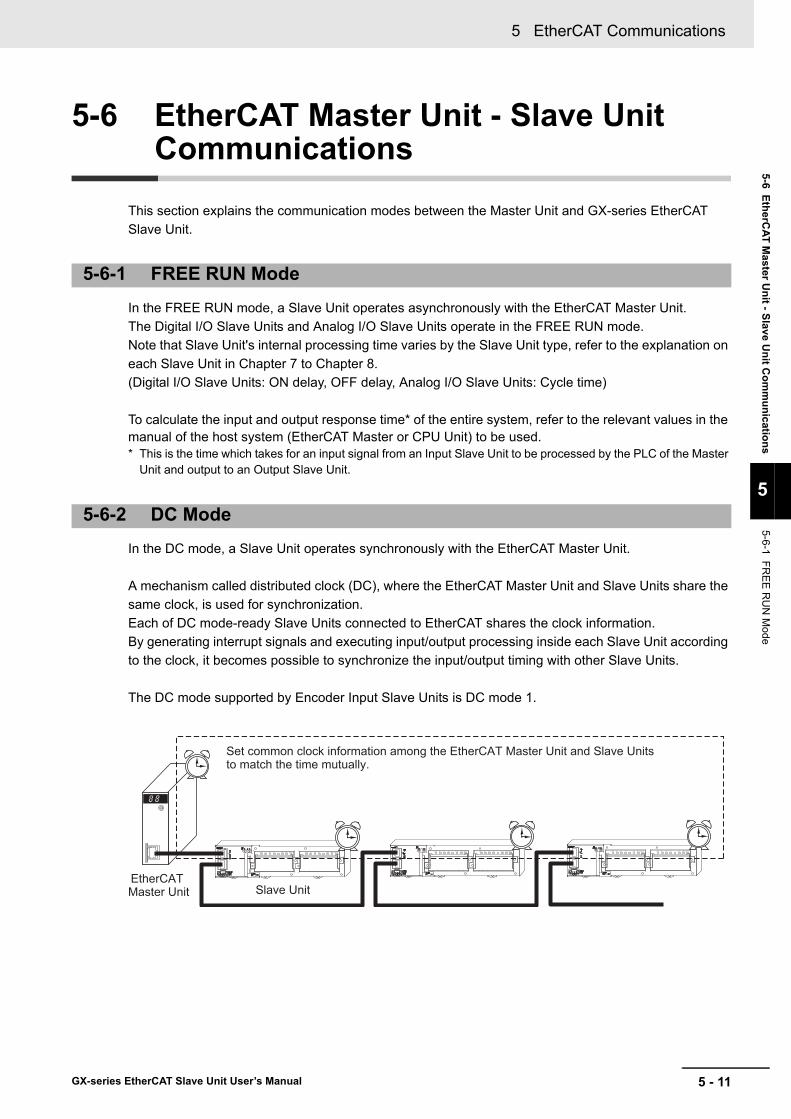
5 - 11
5 EtherCAT Communications
GX-series EtherCAT Slave Unit User’s Manual
5-6 EtherCAT M
aster Unit - Slave U
nit Com
munications
5
5-6-1 FRE
E R
UN
Mode
5-6 EtherCAT Master Unit - Slave Unit Communications
This section explains the communication modes between the Master Unit and GX-series EtherCAT Slave Unit.
In the FREE RUN mode, a Slave Unit operates asynchronously with the EtherCAT Master Unit.The Digital I/O Slave Units and Analog I/O Slave Units operate in the FREE RUN mode.Note that Slave Unit's internal processing time varies by the Slave Unit type, refer to the explanation on each Slave Unit in Chapter 7 to Chapter 8.(Digital I/O Slave Units: ON delay, OFF delay, Analog I/O Slave Units: Cycle time)
To calculate the input and output response time* of the entire system, refer to the relevant values in the manual of the host system (EtherCAT Master or CPU Unit) to be used. * This is the time which takes for an input signal from an Input Slave Unit to be processed by the PLC of the Master
Unit and output to an Output Slave Unit.
In the DC mode, a Slave Unit operates synchronously with the EtherCAT Master Unit.
A mechanism called distributed clock (DC), where the EtherCAT Master Unit and Slave Units share the same clock, is used for synchronization.Each of DC mode-ready Slave Units connected to EtherCAT shares the clock information.By generating interrupt signals and executing input/output processing inside each Slave Unit according to the clock, it becomes possible to synchronize the input/output timing with other Slave Units.
The DC mode supported by Encoder Input Slave Units is DC mode 1.
5-6-1 FREE RUN Mode
5-6-2 DC Mode
Set common clock information among the EtherCAT Master Unit and Slave Units to match the time mutually.
EtherCAT Master Unit Slave Unit
5 EtherCAT Communications
5 - 12 GX-series EtherCAT Slave Unit User’s Manual
Communications cycleThe communications cycle is determined by setting output frequency of Sync0 signal (interrupt signal in DC mode 1).
125 μs, 250 μs, 500 μs, 1 ms, 2 ms, 4 ms
The settings are performed on the EtherCAT Master Unit side. For the setting method, refer to the manual of the EtherCAT Master Unit to be used.
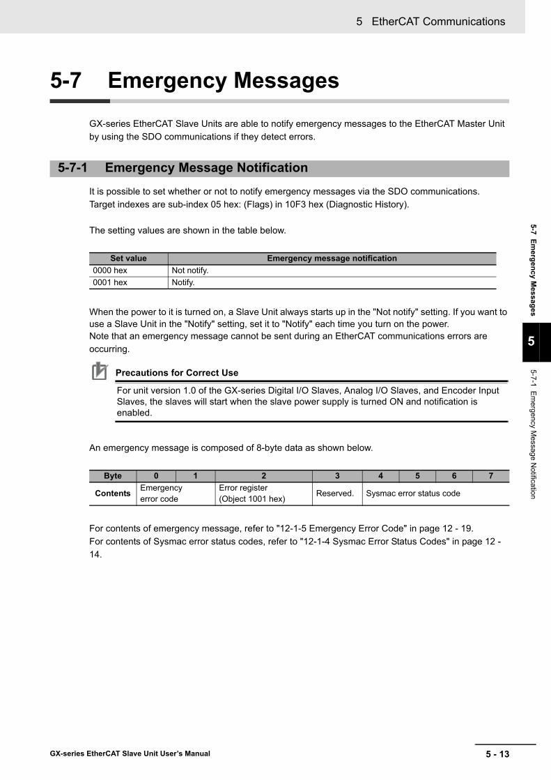
5 - 13
5 EtherCAT Communications
GX-series EtherCAT Slave Unit User’s Manual
5-7 Emergency M
essages
5
5-7-1 Em
ergency Message N
otification
5-7 Emergency Messages
GX-series EtherCAT Slave Units are able to notify emergency messages to the EtherCAT Master Unit by using the SDO communications if they detect errors.
It is possible to set whether or not to notify emergency messages via the SDO communications.Target indexes are sub-index 05 hex: (Flags) in 10F3 hex (Diagnostic History).
The setting values are shown in the table below.
When the power to it is turned on, a Slave Unit always starts up in the "Not notify" setting. If you want to use a Slave Unit in the "Notify" setting, set it to "Notify" each time you turn on the power. Note that an emergency message cannot be sent during an EtherCAT communications errors are occurring.
Precautions for Correct Use
For unit version 1.0 of the GX-series Digital I/O Slaves, Analog I/O Slaves, and Encoder Input Slaves, the slaves will start when the slave power supply is turned ON and notification is enabled.
An emergency message is composed of 8-byte data as shown below.
For contents of emergency message, refer to "12-1-5 Emergency Error Code" in page 12 - 19.For contents of Sysmac error status codes, refer to "12-1-4 Sysmac Error Status Codes" in page 12 - 14.
5-7-1 Emergency Message Notification
Set value Emergency message notification0000 hex Not notify.0001 hex Notify.
Byte 0 1 2 3 4 5 6 7
Contents Emergencyerror code
Error register(Object 1001 hex)
Reserved. Sysmac error status code

5 EtherCAT Communications
5 - 14 GX-series EtherCAT Slave Unit User’s Manual
Any GX-series EtherCAT Slave Unit other than the GX-ILM08C can save up to eight emergency messages in non-volatile memory inside the Slave Unit. The saved messages can be read with SDO communications.Indexes to be read are sub-indexes 06 hex to 0D hex (Diagnosis messages 1 to 8) among 10F3 hex (Diagnosis History).
Diagnosis history is stored from Diagnosis message 1. If 8 errors are stored in order up to Diagnosis message 8, the 9th error onward are saved from Diagnosis message 1 again.
The GX-ILM08C can save a maximum of 64 error records in the error history. For details, refer to the IO-Link System User’s Manual (Cat. No. W570).
History is saved even if emergency messages cannot be sent to the EtherCAT Master Unit due to EtherCAT communications errors or emergency messages are set to "Not notify."Errors that occur for non-volatile memory are not saved in the diagnosis history.
5-7-2 Diagnosis History

5 - 15
5 EtherCAT Communications
GX-series EtherCAT Slave Unit User’s Manual
5-8 Sysmac D
evice Functions
5
5-8 Sysmac Device Functions
“Sysmac devices” is the generic name of control component products that were designed with communications and user interface specifications that are unified for OMRON control components.This functions of these procedures are called Sysmac device functions.This section describes functions that are available when you combine NJ/NX-series or other Machine Automation Controllers with the Automation Software.Starting with unit version 1.1, the GX-series Digital I/O Slaves, Analog I/O Slaves, and Encoder Input Slaves are Sysmac devices and support Sysmac device functions.Starting with unit version 1.0, the GX-series IO-Link Master Unit is a Sysmac device and supports Sysmac device functions.
Sysmac error statusSlaves Units that are Sysmac devices systematically handle errors that occur in the Slave Unit. You can therefore use the Sysmac Studio to check errors and confirm corrections by using the same procedures for all Sysmac devices.Errors are reported in 2002 hex-01 hex (Sysmac Error Status). To display errors that are detected by a Slave Unit on the Sysmac Studio, you must map 2002 hex-01 hex (Sysmac Error Status) to a PDO. In the Sysmac Studio default settings, 2002 hex-01 hex (Sysmac Error Status) is automatically mapped to a PDO in the 512th Transmit PDO Mapping (1BFF hex) assignments.
Reference
• Refer to "A-1-7 Manufacturer Specific Objects" in page A - 29 for information on 2002 hex-01 hex (Sysmac Error Status).
• Refer to "12-1-4 Sysmac Error Status Codes" in page 12 - 14 for errors that are displayed on the Sysmac Studio.

5 EtherCAT Communications
5 - 16 GX-series EtherCAT Slave Unit User’s Manual
Saving node address settingsIf the node address switches are set to 00, the software setting is enabled and the node address that is set on the Sysmac Studio is used.To use the software setting, execute the Write Slave Node Address menu command on the Edit Network Configuration Tab Page for EtherCAT. The software setting will be saved in non-volatile memory in the Slave Unit.
• Software settingThe software setting that is set in the SII (slave information interface) in non-volatile memory in the Slave Unit is used as the node address.
• Node address switch settingThe value that is set on the node address switches on the Slave Unit is used as the node address.
(1)
(2)
(3)
(4) (5)
Node address switches
EtherCAT Slave Unit
Register: 0010 hex
Register: 0012 hex
EtherCAT slave controller
EtherCAT Master Unit
Non-volatile memory
SII
(1) When the power supply is OFF, set the node address switches to 00.
(2) From the master, write the node address to the SII in the Slave Unit.
(3) When the power supply to the Slave Unit is turned ON, the software writes the node address setting to register address 0012 hex.
(4) The EtherCAT Master Unit reads the setting in register address 0012 hex.
(5) The EtherCAT Master Unit writes the value of address 0012 hex to address 0010 hex.
(1)
(2)
(3) (4)
Node address switches
EtherCAT Slave Unit
Register: 0010 hex
Register: 0012 hex
EtherCAT slave controller
EtherCAT Master Unit
Non-volatile memory
SII
(1) When the power supply is OFF, set the node address switches.
(2) When the power supply to the Slave Unit is turned ON, the value that is set on the node address switches is saved in register address 0012 hex.
(3) The EtherCAT Master Unit reads the setting in register address 0012 hex.
(4) The EtherCAT Master Unit writes the value of address 0012 hex to address 0010 hex.

5 - 17
5 EtherCAT Communications
GX-series EtherCAT Slave Unit User’s Manual
5-8 Sysmac D
evice Functions
5
Displaying serial numbersThe serial number that is stored in non-volatile memory in the Slave Unit is given in 1018 hex-04 hex (Serial number). Controllers that support Sysmac device functions can use serial numbers to verify the network configuration.To verify the configuration, set the Serial Number Check Method parameter to Setting = Actual device on the Edit Network Configuration Tab Page for EtherCAT on the Sysmac Studio.A Network Configuration Verification Error will occur if verification fails for the specified method.
Reference
This helps prevent forgetting to set the parameters because a slave device that was replaced is detected.
Conformance to ESI specifications (ETG.2000 S (R) V1.0.1)The ESI specifications define the contents of the EtherCAT slave information (ESI) files.Controllers that support Sysmac device functions can use an optional function that is defined in the ESI specifications to specify backup parameters in the Slave Units.You can back up and restore the backup parameters that are defined in the Slave Units from the Sysmac Studio.
SII data checkingThe SII (slave information interface) contains specific configuration information on the EtherCAT slave that is written in non-volatile memory in the EtherCAT Slave Unit.EtherCAT Slave Units that are Sysmac devices check the information in the SII at the Slave Units.
Precautions for Correct Use
Do not change the SII information with setting software that is produced by other companies.

5 EtherCAT Communications
5 - 18 GX-series EtherCAT Slave Unit User’s Manual
6 - 1
6
GX-series EtherCAT Slave Unit User’s Manual
This chapter explains EtherCAT communication specifications, Slave Units performance specifications, and the specifications of common areas.
6-1 EtherCAT Communications Specifications . . . . . . . . . . . . . . . . . . . . . . . . . 6-26-2 General Specifications . . . . . . . . . . . . . . . . . . . . . . . . . . . . . . . . . . . . . . . . . 6-36-3 Specifications of Common Areas . . . . . . . . . . . . . . . . . . . . . . . . . . . . . . . . . 6-4
6-3-1 Status Indicators . . . . . . . . . . . . . . . . . . . . . . . . . . . . . . . . . . . . . . . . . . . . . . . . 6-46-3-2 Node Address Setting Switches . . . . . . . . . . . . . . . . . . . . . . . . . . . . . . . . . . . . 6-66-3-3 Communications Connectors . . . . . . . . . . . . . . . . . . . . . . . . . . . . . . . . . . . . . . 6-86-3-4 Unit Power Supply Connector . . . . . . . . . . . . . . . . . . . . . . . . . . . . . . . . . . . . . .6-11
Basic Specifications of Slave Units

6 Basic Specifications of Slave Units
6 - 2 GX-series EtherCAT Slave Unit User’s Manual
6-1 EtherCAT Communications Specifications
This section provides the communications specifications of GX-series Digital I/O Slave Units, Analog I/O Slave Units, and Encoder Input Slave Units.Refer to "10-4-1 Specifications" in page 10 - 7 for the EtherCAT communications specifications for the GX-ILM08C.
Item SpecificationCommunication protocol Dedicated protocol for EtherCATModulation Base bandBaud rate 100 MbpsPhysical layer 100BASE-TX (IEEE802.3)
ConnectorsRJ45 × 2 (Shielded)
CN IN: EtherCAT inputCN OUT: EtherCAT output
Topology Daisy chain
Communications mediaCategory 5 or higher (cable with double, aluminum tape and braided shielding is recommended.)
Communications distance Distance between nodes (Slave Units): 100 m max. Noise immunity Conforms to IEC 61000-4-4, 1 kV or higherNode address setting method
Set on decimal node address switches or with a Configuration Tool.
Node address range1 to 99: Node address switch setting1 to 65535: Set with Configuration Tool
Indicator
PWR × 1L/A IN (Link/Activity IN) × 1L/A OUT (Link/Activity OUT) × 1RUN × 1ERR × 1
Process data Fixed PDO mappingPDO size/node 2 to 256 bytesMailbox Emergency messages, SDO requests, SDO responses, and SDO informationSYNCHRONIZATION mode
Digital I/O Slave Unit and Analog I/O Slave Unit: Free Run mode (asynchronous) Encoder Input Slave Unit: DC mode 1

6 - 3
6 Basic Specifications of Slave Units
GX-series EtherCAT Slave Unit User’s Manual
6-2 General Specifications
6
6-2 General Specifications
This section provides the general specifications of GX-series Digital I/O Slave Units, Analog I/O Slave Units, and Encoder Input Slave Units.Refer to "10-4-1 Specifications" in page 10 - 7 for the general specifications for the GX-ILM08C.
* Applicable only to 2-tier terminal block and 3-tier terminal block type Slave Units.
Item SpecificationUnit power supply voltage 20.4 to 26.4 VDC (24 VDC −15% to +10%)I/O power supply voltage 20.4 to 26.4 VDC (24 VDC −15% to +10%)Noise immunity Conforms to IEC 61000-4-4, 2 kV (power line).
Vibration resistance
Malfunction 10 to 60 Hz with amplitude of 0.7 mm, 60 to 150Hz and 50 m/s2 in each of X, Y, and Z directions for 80 minutes<GX-OC1601 Relay Output Unit only>10 to 55 Hz with double-amplitude of 0.7 mm
Shock resistance150 m/s2 with amplitude of 0.7 mm<GX-OC1601 Relay Output Unit only>100 m/s2 (3 times each in 6 directions on 3 axes)
Dielectric strength 600 VAC (between isolated circuits)Insulation resistance 20 MΩ or more (between isolated circuits)Ambient operating temperature
−10 to 55 °C
Ambient operating humidity
25% to 85% (with no condensation)
Ambient operating atmosphere
No corrosive gases
Storage temperature −25 to 65 °CStorage humidity 25% to 85% (with no condensation)Terminal block screws tightening torque*
M3 wiring screws: 0.5 N • mM3 terminal block mounting screws: 0.5 N • m
Mounting method 35-mm DIN track mounting

6 Basic Specifications of Slave Units
6 - 4 GX-series EtherCAT Slave Unit User’s Manual
6-3 Specifications of Common Areas
This section explains the specifications of indicator, switches, and connectors commonly mounted in each Slave Unit.
It indicates the current state of an EtherCAT Slave Unit.
Indicates the unit power supply state.
Indicates the communication state (input side).
Indicates the communication state (output side).
6-3-1 Status Indicators
[PWR] indicator
Color State Contents
GreenOFF Unit power OFF stateON The unit power (24 VDC) is supplied to the Slave Unit.
[L/A IN] indicator
Color State Contents
GreenOFF Link not established in physical layerFlickering In operation after establishing linkON Link established in physical layer
[L/A OUT] indicator
Color State Contents
GreenOFF Link not established in physical layerFlickering In operation after establishing linkON Link established in physical layer
L/A IN
L/A OUT
RUN
ERR
PWR

6 - 5
6 Basic Specifications of Slave Units
GX-series EtherCAT Slave Unit User’s Manual
6-3 Specifications of Com
mon A
reas
6
6-3-1 Status Indicators
It indicates the operation state.
For details on each state, refer to "5-3 Communications State Transitions" in page 5 - 4.
It indicates the information of an error.
Reference
The timing of each flashing state of indicator is as follows.
[RUN] indicator
Color State Contents
Green
OFF Init stateBlinking Pre-Operational stateSingle flash Safe-Operational stateON Operational state
[ERR] indicator
Color State Contents
Red
OFF No errorBlinking Communications setting errorSingle flash Synchronization error or communications data errorDouble flash Application WDT timeoutFlickering Boot errorON PDI WDT timeout
on
off
on
off
on
off
on
off
Flickering
Blinking
Single flash
Double flash
50 ms
200 ms 200 ms
200 ms 200 ms
1000 ms
200 ms 200 ms 200 ms
1000 ms
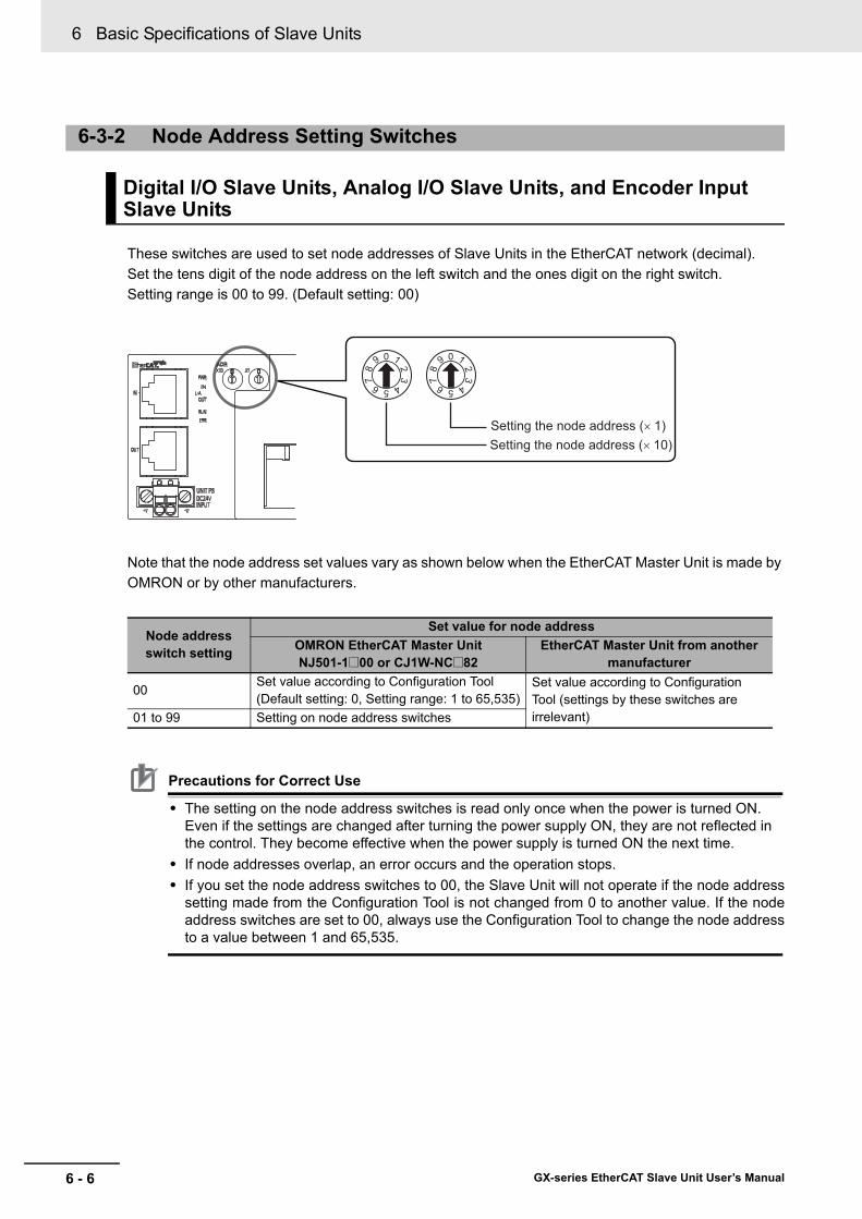
6 Basic Specifications of Slave Units
6 - 6 GX-series EtherCAT Slave Unit User’s Manual
These switches are used to set node addresses of Slave Units in the EtherCAT network (decimal).Set the tens digit of the node address on the left switch and the ones digit on the right switch.Setting range is 00 to 99. (Default setting: 00)
Note that the node address set values vary as shown below when the EtherCAT Master Unit is made by OMRON or by other manufacturers.
Precautions for Correct Use
• The setting on the node address switches is read only once when the power is turned ON. Even if the settings are changed after turning the power supply ON, they are not reflected in the control. They become effective when the power supply is turned ON the next time.
• If node addresses overlap, an error occurs and the operation stops.• If you set the node address switches to 00, the Slave Unit will not operate if the node address
setting made from the Configuration Tool is not changed from 0 to another value. If the nodeaddress switches are set to 00, always use the Configuration Tool to change the node addressto a value between 1 and 65,535.
6-3-2 Node Address Setting Switches
Digital I/O Slave Units, Analog I/O Slave Units, and Encoder Input Slave Units
Node address switch setting
Set value for node addressOMRON EtherCAT Master UnitNJ501-1@00 or CJ1W-NC@82
EtherCAT Master Unit from another manufacturer
00Set value according to Configuration Tool(Default setting: 0, Setting range: 1 to 65,535)
Set value according to Configuration Tool (settings by these switches are irrelevant)01 to 99 Setting on node address switches
Setting the node address (× 10)Setting the node address (× 1)
0 1
23
456
78
90 1
23
456
78
9
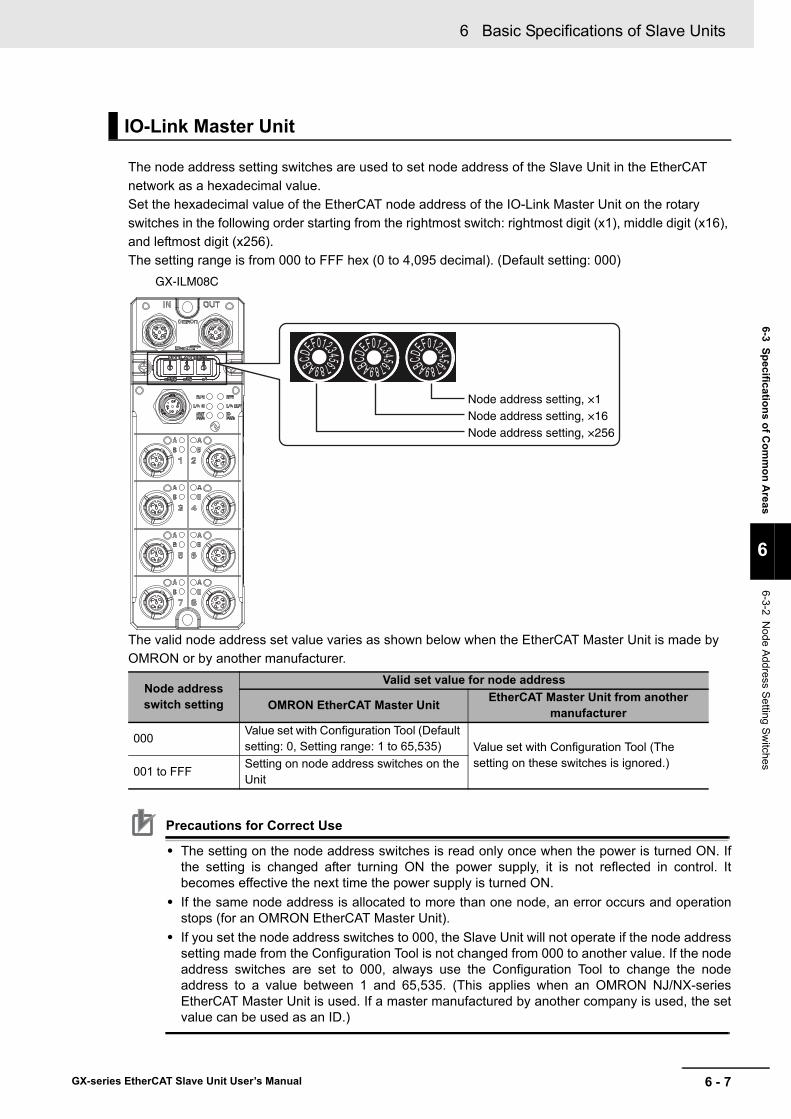
6 - 7
6 Basic Specifications of Slave Units
GX-series EtherCAT Slave Unit User’s Manual
6-3 Specifications of Com
mon A
reas
6
6-3-2 Node A
ddress Setting Switches
The node address setting switches are used to set node address of the Slave Unit in the EtherCAT network as a hexadecimal value.Set the hexadecimal value of the EtherCAT node address of the IO-Link Master Unit on the rotary switches in the following order starting from the rightmost switch: rightmost digit (x1), middle digit (x16), and leftmost digit (x256).The setting range is from 000 to FFF hex (0 to 4,095 decimal). (Default setting: 000)
The valid node address set value varies as shown below when the EtherCAT Master Unit is made by OMRON or by another manufacturer.
Precautions for Correct Use
• The setting on the node address switches is read only once when the power is turned ON. Ifthe setting is changed after turning ON the power supply, it is not reflected in control. Itbecomes effective the next time the power supply is turned ON.
• If the same node address is allocated to more than one node, an error occurs and operationstops (for an OMRON EtherCAT Master Unit).
• If you set the node address switches to 000, the Slave Unit will not operate if the node addresssetting made from the Configuration Tool is not changed from 000 to another value. If the nodeaddress switches are set to 000, always use the Configuration Tool to change the nodeaddress to a value between 1 and 65,535. (This applies when an OMRON NJ/NX-seriesEtherCAT Master Unit is used. If a master manufactured by another company is used, the setvalue can be used as an ID.)
IO-Link Master Unit
Node address switch setting
Valid set value for node address
OMRON EtherCAT Master Unit EtherCAT Master Unit from another manufacturer
000Value set with Configuration Tool (Default setting: 0, Setting range: 1 to 65,535) Value set with Configuration Tool (The
setting on these switches is ignored.)001 to FFF
Setting on node address switches on the Unit
GX-ILM08C
0123456789ABCDEF 0123456789ABCDEF 0123456789ABCDEF
Node address setting, ×1Node address setting, ×16Node address setting, ×256

6 Basic Specifications of Slave Units
6 - 8 GX-series EtherCAT Slave Unit User’s Manual
The Connectors are used to connect the communications cables.
RJ45 connectors are used for the communications connectors as shown below.
The specifications are shown below.
• Electrical characteristics: Conforms to the IEEE 802.3 standard.• Connector structure: RJ45 8-pin modular connector (conforms to ISO 8877)• Terminal arrangement
6-3-3 Communications Connectors
Digital I/O Slave Units, Analog I/O Slave Units, and Encoder Input Slave Units
Pin No. Signal name Abbreviation1 Send data + TD +2 Send data − TD −3 Receive data + RD +4 Not used −5 Not used −6 Receive data − RD −7 Not used −8 Not used −Hood Frame ground FG
CN1
CN2
1
8
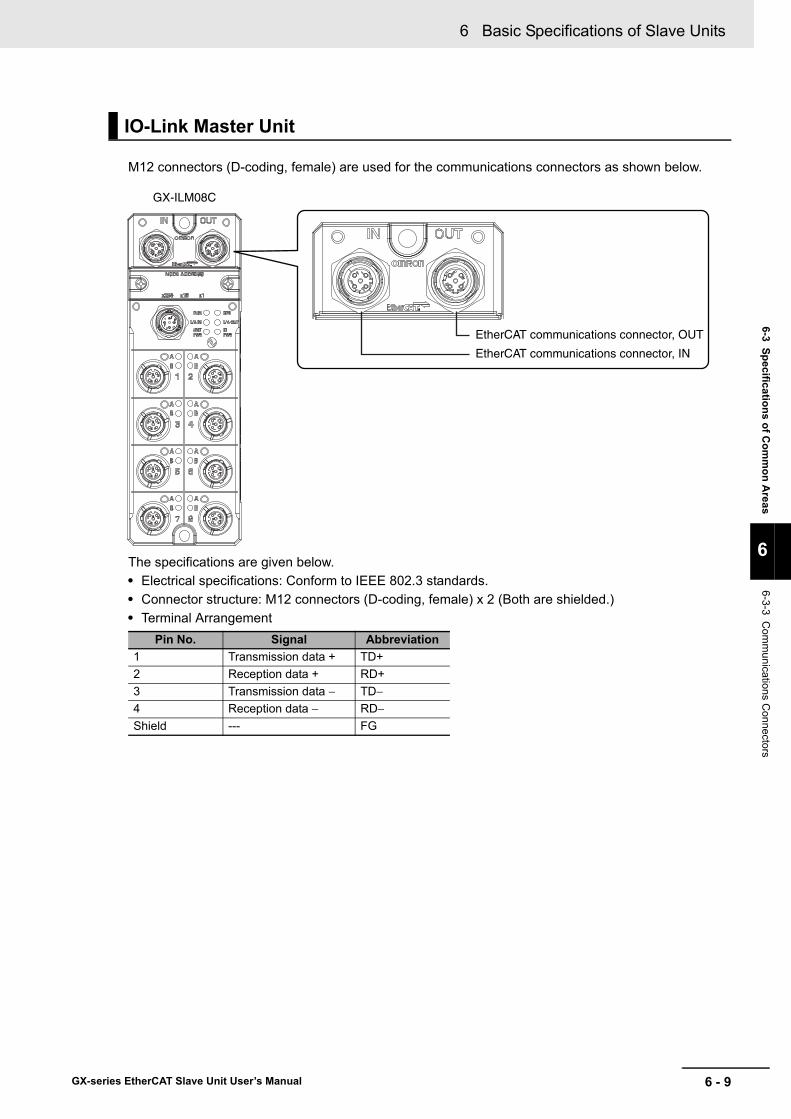
6 - 9
6 Basic Specifications of Slave Units
GX-series EtherCAT Slave Unit User’s Manual
6-3 Specifications of Com
mon A
reas
6
6-3-3 Com
munications C
onnectors
M12 connectors (D-coding, female) are used for the communications connectors as shown below.
The specifications are given below.• Electrical specifications: Conform to IEEE 802.3 standards.• Connector structure: M12 connectors (D-coding, female) x 2 (Both are shielded.)• Terminal Arrangement
IO-Link Master Unit
Pin No. Signal Abbreviation1 Transmission data + TD+2 Reception data + RD+3 Transmission data − TD−4 Reception data − RD−Shield --- FG
GX-ILM08C
EtherCAT communications connector, OUT
EtherCAT communications connector, IN

6 Basic Specifications of Slave Units
6 - 10 GX-series EtherCAT Slave Unit User’s Manual
• Recommended Cables with Connectors
(1) Connector ModelH: Cable with Connector on One EndW: Cable with Connectors on Both Ends
(2) TypeT: Ethernet (mating section: M12, D coding)
(3) Number of Pins4: 4 pins
(4) Contact Plating2: Gold-plated, 0.4 μm
(5) Cable Connection Direction (M12 Connector)1: Straight2: Right-angle
(6) Cable LengthA: 0.3 mB: 0.5 mC: 1 mD: 2 mE: 3 mG: 5 mJ: 10 mK: 15 m
(7) Connectors0: M12 plug on one end1: M12 socket on one end and M12 plug on the other end2: M12 plugs on both endsC: M12 plug on one end and RJ45 plug on the other endD: RJ45 plugs on both endsE: M12 socket on one end and RJ45 plug on the other end
(8) CableK: Standard cableKR: Flexible cable
XS5� -T 4 2 � -�M� -��― ― ― ― ― ― ― ―(1) (2) (3) (4) (5) (6) (7) (8)

6 - 11
6 Basic Specifications of Slave Units
GX-series EtherCAT Slave Unit User’s Manual
6-3 Specifications of Com
mon A
reas
6
6-3-4 Unit P
ower S
upply Connector
The Connector is used to connect the unit power supply (24 VDC).
• Connector type: Spring connection connector with fixing screw (2-pin)
• Supported pin terminal diameter: 0.25 mm2 to 0.5 mm2/AWG24 to AWG20(Pin terminal with isolation sleeve used)
For types of recommended pin terminals, refer to "4-3-3 Connecting the Unit Power Supply" in page 4 - 9.
6-3-4 Unit Power Supply Connector
Digital I/O Slave Units, Analog I/O Slave Units, and Encoder Input Slave Units
Name+V −V
24 VDC0 VDC
Fixing screw
+V terminal
−Vterminal
Specification
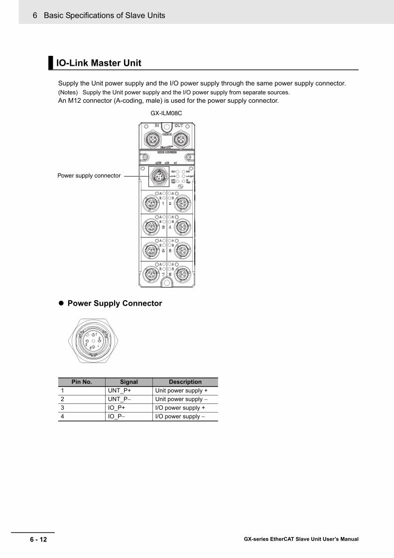
6 Basic Specifications of Slave Units
6 - 12 GX-series EtherCAT Slave Unit User’s Manual
Supply the Unit power supply and the I/O power supply through the same power supply connector.(Notes) Supply the Unit power supply and the I/O power supply from separate sources.An M12 connector (A-coding, male) is used for the power supply connector.
Power Supply Connector
IO-Link Master Unit
Pin No. Signal Description1 UNT_P+ Unit power supply +2 UNT_P− Unit power supply −3 IO_P+ I/O power supply +4 IO_P− I/O power supply −
Power supply connector
GX-ILM08C

6 - 13
6 Basic Specifications of Slave Units
GX-series EtherCAT Slave Unit User’s Manual
6-3 Specifications of Com
mon A
reas
6
6-3-5 I/O P
ower S
upply Connector
Connect I/O power supply for external device operation (24 VDC).
The I/O power supply connector is mounted on the following type of Slave Unit with e-CON connector and output contacts.
GX-OD1618/OD1628/MD1618/MD1628/OD3218/OD3228/MD3218/MD3228
• Connector type: Spring connection connector with fixing screw (4-pin)
• Supported pin terminal diameter: 0.25 mm2 to 0.5 mm2/AWG24 to AWG20(Pin terminal with isolation sleeve used)
For types of recommended pin terminals, refer to "4-3-4 Connecting the I/O Power Supply" in page 4 - 11.
I/O power is supplied through the power supply connector. Refer to "6-3-4 Unit Power Supply Connector" in page 6 - 11.
6-3-5 I/O Power Supply Connector
Digital I/O Slave Units, Analog I/O Slave Units, and Encoder Input Slave Units
IO-Link Master Units
NameV G
24 VDC0 VDC
Specification
V terminal
G terminal

6 Basic Specifications of Slave Units
6 - 14 GX-series EtherCAT Slave Unit User’s Manual
7 - 1
7
GX-series EtherCAT Slave Unit User’s Manual
This chapter explains the overview of the Digital I/O Slave Unit.
7-1 Digital I/O Slave Unit . . . . . . . . . . . . . . . . . . . . . . . . . . . . . . . . . . . . . . . . . . . 7-27-2 I/O Data Allocation (PDO Mapping) . . . . . . . . . . . . . . . . . . . . . . . . . . . . . . . 7-3
7-2-1 Input Data Allocation . . . . . . . . . . . . . . . . . . . . . . . . . . . . . . . . . . . . . . . . . . . . . 7-37-2-2 Output Data Allocation . . . . . . . . . . . . . . . . . . . . . . . . . . . . . . . . . . . . . . . . . . . 7-5
7-3 Functions of Digital I/O Slave Units . . . . . . . . . . . . . . . . . . . . . . . . . . . . . . . 7-77-3-1 Input Filter . . . . . . . . . . . . . . . . . . . . . . . . . . . . . . . . . . . . . . . . . . . . . . . . . . . . . 7-77-3-2 Error Mode Output . . . . . . . . . . . . . . . . . . . . . . . . . . . . . . . . . . . . . . . . . . . . . . 7-8
7-4 Specifications for Each Slave Unit . . . . . . . . . . . . . . . . . . . . . . . . . . . . . . . . 7-97-4-1 2-tier Terminal Block Type 16-point Input Slave Unit GX-ID1611/ID1621 . . . 7-107-4-2 2-tier Terminal Block Type 16-point Output Slave Unit GX-OD1611/OD1621 7-147-4-3 2-tier Terminal Block Relay Type 16-point Output Slave Unit GX-OC1601 . . 7-187-4-4 2-tier Terminal Block Type 8-point Input and 8-point Output Slave Unit
GX-MD1611/MD1621 . . . . . . . . . . . . . . . . . . . . . . . . . . . . . . . . . . . . . . . . . . . 7-227-4-5 3-tier Terminal Block Type 16-point Input Slave Unit GX-ID1612/ID1622 . . . . 7-287-4-6 3-tier Terminal Block Type 16-point Output Slave Unit GX-OD1612/OD1622 7-337-4-7 3-tier Terminal Block Type 8-point Input and 8-point Output Slave Unit
GX-MD1612/MD1622 . . . . . . . . . . . . . . . . . . . . . . . . . . . . . . . . . . . . . . . . . . . 7-387-4-8 e-CON Connector Type 16-point Input Slave Unit GX-ID1618/ID1628 . . . . . 7-447-4-9 e-CON Connector Type 16-point Output Slave Unit GX-OD1618/OD1628 . . 7-487-4-10 e-CON Connector Type 8-point Input and 8-point Output Slave Unit
GX-MD1618/MD1628 . . . . . . . . . . . . . . . . . . . . . . . . . . . . . . . . . . . . . . . . . . . 7-537-4-11 e-CON Connector Type 32-point Input Slave Unit GX-ID3218/ID3228 . . . . . 7-597-4-12 e-CON Connector Type 32-point Output Slave Unit GX-OD3218/OD3228 . . 7-647-4-13 e-CON Connector Type 16-point Input and 16-point Output Slave Unit
GX-MD3218/MD3228 . . . . . . . . . . . . . . . . . . . . . . . . . . . . . . . . . . . . . . . . . . . 7-69
7-5 Mounting Dimensions . . . . . . . . . . . . . . . . . . . . . . . . . . . . . . . . . . . . . . . . . 7-757-5-1 2-tier Terminal Block Type . . . . . . . . . . . . . . . . . . . . . . . . . . . . . . . . . . . . . . . 7-757-5-2 3-tier Terminal Block Type . . . . . . . . . . . . . . . . . . . . . . . . . . . . . . . . . . . . . . . 7-767-5-3 e-CON Connector Type . . . . . . . . . . . . . . . . . . . . . . . . . . . . . . . . . . . . . . . . . 7-77
Digital I/O Slave Unit

7 Digital I/O Slave Unit
7 - 2 GX-series EtherCAT Slave Unit User’s Manual
7-1 Digital I/O Slave Unit
Digital I/O Slave Units refer to slaves with processing functions for digital I/O data (ON/OFF signals). Moreover, this Slave Unit has the input filter function (input only) and the output setting function at communications error (output only).

7 - 3
7 Digital I/O Slave Unit
GX-series EtherCAT Slave Unit User’s Manual
7-2 I/O D
ata Allocation (PD
O M
apping)
7
7-2-1 Input Data A
llocation
7-2 I/O Data Allocation (PDO Mapping)
I/O data of Digital I/O Slave Units are allocated to the input/output areas of the I/O memory of the EtherCAT Master Unit, respectively.
For the detailed explanation of allocation method, refer to the manual of EtherCAT Master Unit to be connected.
The input data for a Digital I/O Slave Unit consists of the input data for the Slave Unit and the input data
for the Expansion Unit (when one is mounted). You can also assign the Sysmac error status. *1 The input data is assigned in this order in byte increments.*1 Unit version 1.1 or later only.
8-point Input Slave Unit
16-point Input Slave Unit
32-point Input Slave Unit
8-point Expansion Unit
7-2-1 Input Data Allocation
Input data allocation example
Offset (byte) 7 bit 0 bit
0 Input data of the Slave Unit (7 to 0 bit)
+1 Reserved
Offset (byte) 7 bit 0 bit
0 Input data of the Slave Unit (7 to 0 bit)
+1 Input data of the Slave Unit (15 to 8 bit)
Offset (byte) 7 bit 0 bit
0 Input data of the Slave Unit (7 to 0 bit)
+1 Input data of the Slave Unit (15 to 8 bit)
+2 Input data of the Slave Unit (23 to 16 bit)
+3 Input data of the Slave Unit (31 to 24 bit)
Offset (byte) 7 bit 0 bit
0 Input data of the Expansion Unit (7 to 0 bit)
+1 Reserved
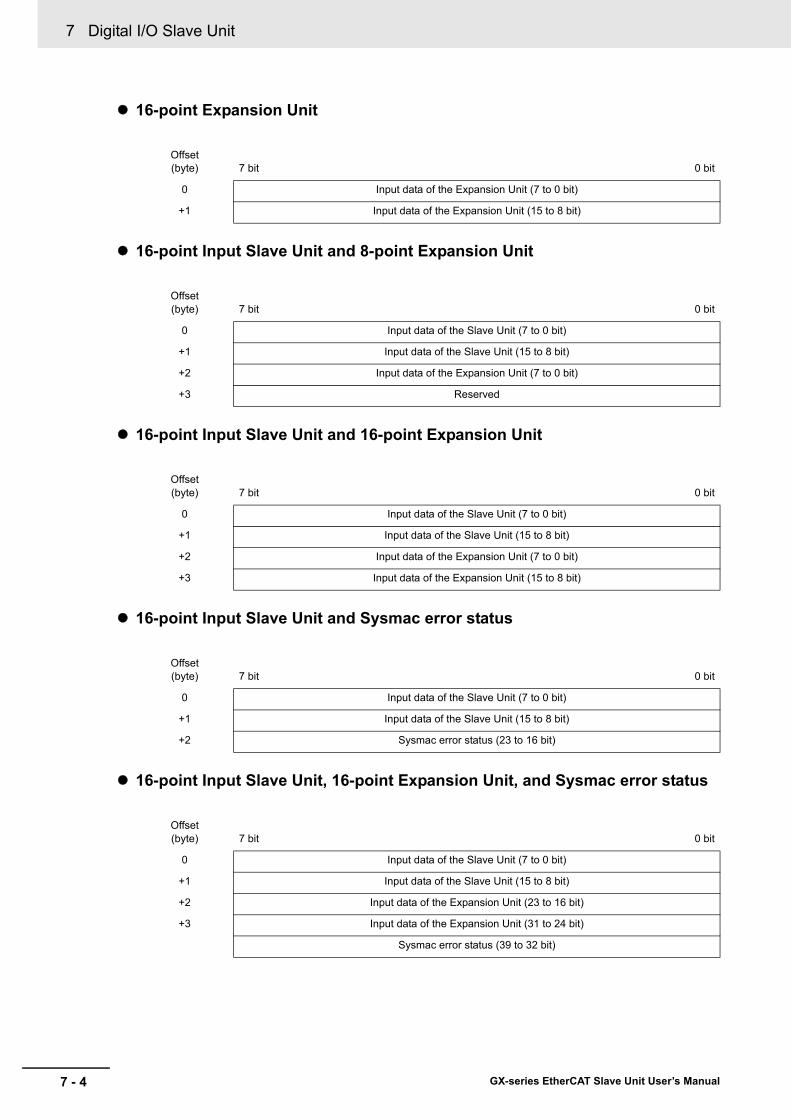
7 Digital I/O Slave Unit
7 - 4 GX-series EtherCAT Slave Unit User’s Manual
16-point Expansion Unit
16-point Input Slave Unit and 8-point Expansion Unit
16-point Input Slave Unit and 16-point Expansion Unit
16-point Input Slave Unit and Sysmac error status
16-point Input Slave Unit, 16-point Expansion Unit, and Sysmac error status
Offset(byte) 7 bit 0 bit
0 Input data of the Expansion Unit (7 to 0 bit)
+1 Input data of the Expansion Unit (15 to 8 bit)
Offset(byte) 7 bit 0 bit
0 Input data of the Slave Unit (7 to 0 bit)
+1 Input data of the Slave Unit (15 to 8 bit)
+2 Input data of the Expansion Unit (7 to 0 bit)
+3 Reserved
Offset(byte) 7 bit 0 bit
0 Input data of the Slave Unit (7 to 0 bit)
+1 Input data of the Slave Unit (15 to 8 bit)
+2 Input data of the Expansion Unit (7 to 0 bit)
+3 Input data of the Expansion Unit (15 to 8 bit)
Offset(byte) 7 bit 0 bit
0 Input data of the Slave Unit (7 to 0 bit)
+1 Input data of the Slave Unit (15 to 8 bit)
+2 Sysmac error status (23 to 16 bit)
Offset(byte) 7 bit 0 bit
0 Input data of the Slave Unit (7 to 0 bit)
+1 Input data of the Slave Unit (15 to 8 bit)
+2 Input data of the Expansion Unit (23 to 16 bit)
+3 Input data of the Expansion Unit (31 to 24 bit)
Sysmac error status (39 to 32 bit)

7 - 5
7 Digital I/O Slave Unit
GX-series EtherCAT Slave Unit User’s Manual
7-2 I/O D
ata Allocation (PD
O M
apping)
7
7-2-2 Output D
ata Allocation
Sysmac error status
Output data of Digital I/O Slave Units consists of 2 types: Output data of the Slave Unit and output data of Expansion Unit (if mounted). The data is allocated in this order in units of bytes.
8-point Output Slave Unit
16-point Output Slave Unit
32-point Output Slave Unit
8-point Expansion Unit
Offset(byte) 7 bit 0 bit
0 Sysmac error status (7 to 0 bit)
7-2-2 Output Data Allocation
Output data allocation example
Offset (byte) 7 bit 0 bit
0 Output data of the Slave Unit (7 to 0 bit)
+1 Reserved
Offset (byte) 7 bit 0 bit
0 Output data of the Slave Unit (7 to 0 bit)
+1 Output data of the Slave Unit (15 to 8 bit)
Offset (byte) 7 bit 0 bit
0 Output data of the Slave Unit (7 to 0 bit)
+1 Output data of the Slave Unit (15 to 8 bit)
+2 Output data of the Slave Unit (23 to 16 bit)
+3 Output data of the Slave Unit (31 to 24 bit)
Offset (byte) 7 bit 0 bit
0 Output data of the Expansion Unit (7 to 0 bit)
+1 Reserved

7 Digital I/O Slave Unit
7 - 6 GX-series EtherCAT Slave Unit User’s Manual
16-point Expansion Unit
16-point Output Slave Unit and 8-point Expansion Unit
16-point Output Slave Unit and 16-point Expansion Unit
Offset (byte) 7 bit 0 bit
0 Output data of the Expansion Unit (7 to 0 bit)
+1 Output data of the Expansion Unit (15 to 8 bit)
Offset (byte) 7 bit 0 bit
0 Output data of the Slave Unit (7 to 0 bit)
+1 Output data of the Slave Unit (15 to 8 bit)
+2 Output data of the Expansion Unit (7 to 0 bit)
+3 Reserved
Offset (byte) 7 bit 0 bit
0 Output data of the Slave Unit (7 to 0 bit)
+1 Output data of the Slave Unit (15 to 8 bit)
+2 Output data of the Expansion Unit (7 to 0 bit)
+3 Output data of the Expansion Unit (15 to 8 bit)
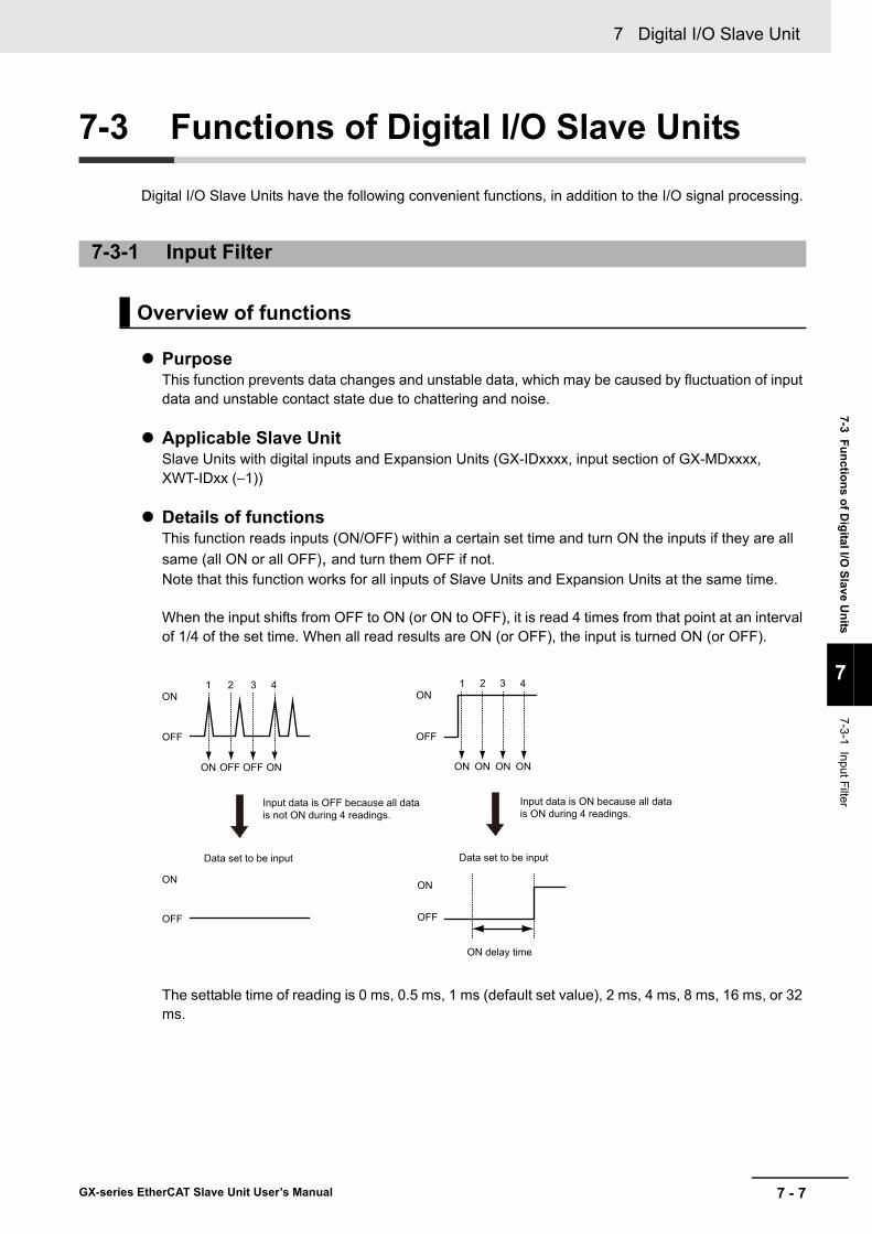
7 - 7
7 Digital I/O Slave Unit
GX-series EtherCAT Slave Unit User’s Manual
7-3 Functions of Digital I/O
Slave Units
7
7-3-1 Input Filter
7-3 Functions of Digital I/O Slave Units
Digital I/O Slave Units have the following convenient functions, in addition to the I/O signal processing.
PurposeThis function prevents data changes and unstable data, which may be caused by fluctuation of input data and unstable contact state due to chattering and noise.
Applicable Slave UnitSlave Units with digital inputs and Expansion Units (GX-IDxxxx, input section of GX-MDxxxx, XWT-IDxx (−1))
Details of functionsThis function reads inputs (ON/OFF) within a certain set time and turn ON the inputs if they are all same (all ON or all OFF), and turn them OFF if not.Note that this function works for all inputs of Slave Units and Expansion Units at the same time.
When the input shifts from OFF to ON (or ON to OFF), it is read 4 times from that point at an interval of 1/4 of the set time. When all read results are ON (or OFF), the input is turned ON (or OFF).
The settable time of reading is 0 ms, 0.5 ms, 1 ms (default set value), 2 ms, 4 ms, 8 ms, 16 ms, or 32 ms.
7-3-1 Input Filter
Overview of functions
1 2 3 4ON
ON ON
OFF
OFF OFF
ON
OFF
Data set to be input
Input data is OFF because all data is not ON during 4 readings.
ON
OFF
OFF
ON
1 2 3 4
ON ON ON ON
Data set to be input
ON delay time
Input data is ON because all data is ON during 4 readings.

7 Digital I/O Slave Unit
7 - 8 GX-series EtherCAT Slave Unit User’s Manual
Note that when this function is used, the timing when the contact actually turns ON (or OFF) is delayed for the set time (ON delay time).The ON delay time is expressed by "input delay time (time required to read input) + input filter time."Moreover, if the input filter is used for the Expansion Units as well, the ON delay time becomes longer because the input delay time is longer than when only Slave Unit is used.
The settings are made using the SDO communication.The target index is 3000 hex.For the set values, refer to the information in the corresponding index of "Appendix A-1 Object Dictionary" in Page A - 31.
PurposeThis function provides selection whether to hold or clear the outputs if signals from the EtherCAT Master Unit cannot be received any longer due to communications errors.
Applicable Slave UnitSlave Units with digital outputs and Expansion Units (GX-ODxxxx, GX-OC1601, output section of GX-MDxxxx, XWT-ODxx (−1))
Details of functionsSets whether to hold or clear the output at communications errors.It is possible to make setting for each contact. (Default setting: Clear all outputs)
The settings are made using the SDO communication.The target index is set as follows according to the number of outputs of a single Slave Unit (including Expansion Units mounted).
For the set value, refer to the information of the corresponding index of "Appendix A-1 Object Dictionary" in Page A - 37.
Setting method
7-3-2 Error Mode Output
Overview of functions
Setting method
Total output
capacity
Output Unitcapacity
Expansion UnitOutput capacity Applicable index
8 points8 points −
6306 hex− 8 points
16 points16 points −− 16 points
24 points 16 points 8 points6326 hex
32 points16 points 16 points32 points −

7 - 9
7 Digital I/O Slave Unit
GX-series EtherCAT Slave Unit User’s Manual
7-4 Specifications for Each Slave Unit
7
7-4 Specifications for Each Slave Unit
This section shows the specification of Digital I/O Slave Units, names and functions of each part, internal circuit diagram, and wiring diagram.Refer to the following corresponding page to each model.
Type Model
Reference page
Specification Names and functions
Internal circuits diagram
Wiring diagram
2-tier terminal block type
GX-ID1611GX-ID1621
7-10 7-11 7-12 7-13
GX-OD1611GX-OD1621
7-14 7-15 7-16 7-17
GX-OC1601 7-18 7-19 7-21 7-21GX-MD1611GX-MD1621
7-22 7-24 7-25 7-26
3-tier terminal block type
GX-ID1612GX-ID1622
7-28 7-29 7-30 7-31
GX-OD1612GX-OD1622
7-33 7-34 7-35 7-36
GX-MD1612GX-MD1622
7-38 7-40 7-41 7-42
e-CON connector type
GX-ID1618GX-ID1628
7-44 7-45 7-46 7-47
GX-OD1618GX-OD1628
7-48 7-49 7-50 7-51
GX-MD1618GX-MD1628
7-53 7-55 7-56 7-57
GX-ID3218GX-ID3228
7-59 7-60 7-62 7-63
GX-OD3218GX-OD3228
7-64 7-65 7-66 7-67
GX-MD3218GX-MD3228
7-69 7-71 7-72 7-73

7 Digital I/O Slave Unit
7 - 10 GX-series EtherCAT Slave Unit User’s Manual
Notes For the I/O power supply current value to V and G terminals, refer to "A-5 I/O Power Supply Current" in Page A - 72.
7-4-1 2-tier Terminal Block Type 16-point Input Slave Unit GX-ID1611/ID1621
Specification
ItemSpecification
GX-ID1611 GX-ID1621Input capacity 16 pointsInternal I/O common NPN PNP
ON voltage15 VDC min. (between each input terminal and the V terminal)
15 VDC min. (between each input terminal and the G terminal)
OFF voltage5 VDC max. (between each input terminal and the V terminal)
5 VDC max. (between each input terminal and the G terminal)
OFF current 1.0 mA max.
Input current6.0 mA max./input (at 24-VDC)3.0 mA max./input (at 17-VDC)
ON delay 0.1 ms max.OFF delay 0.2 ms max.
Input filter valueWithout filter, 0.5 ms, 1 ms, 2 ms, 4 ms, 8 ms, 16 ms, 32 ms(Default setting: 1 ms)
Number of circuits per common
16 inputs/common
Input indicators LED display (yellow)Isolation method Photocoupler isolationI/O power supply method Supply by I/O power supplyUnit power supply current consumption
90 mA max. (for 20.4 to 26.4-VDC power supply voltage)
I/O power supply current consumption
10 mA max. (for 20.4 to 26.4-VDC power supply voltage)
Weight 180 g max.Expansion functions EnabledShort-circuit protection function
No
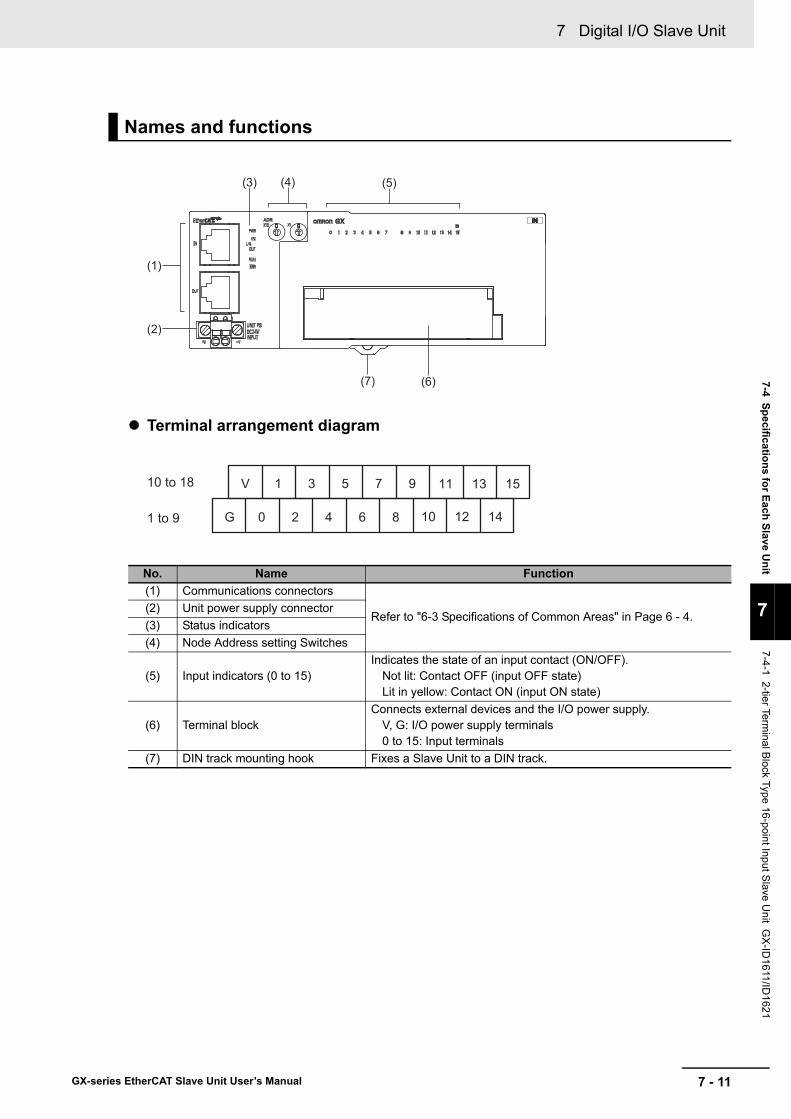
7 - 11
7 Digital I/O Slave Unit
GX-series EtherCAT Slave Unit User’s Manual
7-4 Specifications for Each Slave Unit
7
7-4-1 2-tier Terminal B
lock Type 16-point Input Slave U
nit GX
-ID1611/ID
1621
Terminal arrangement diagram
Names and functions
No. Name Function(1) Communications connectors
Refer to "6-3 Specifications of Common Areas" in Page 6 - 4.(2) Unit power supply connector(3) Status indicators(4) Node Address setting Switches
(5) Input indicators (0 to 15)Indicates the state of an input contact (ON/OFF).
Not lit: Contact OFF (input OFF state)Lit in yellow: Contact ON (input ON state)
(6) Terminal blockConnects external devices and the I/O power supply.
V, G: I/O power supply terminals0 to 15: Input terminals
(7) DIN track mounting hook Fixes a Slave Unit to a DIN track.
(5)
(1)
(6)
(2)
(3) (4)
(7)
10 to 18
1 to 9
V 1 3 5 7 9
G 0 2 4 6 8 10 12 14
11 13 15
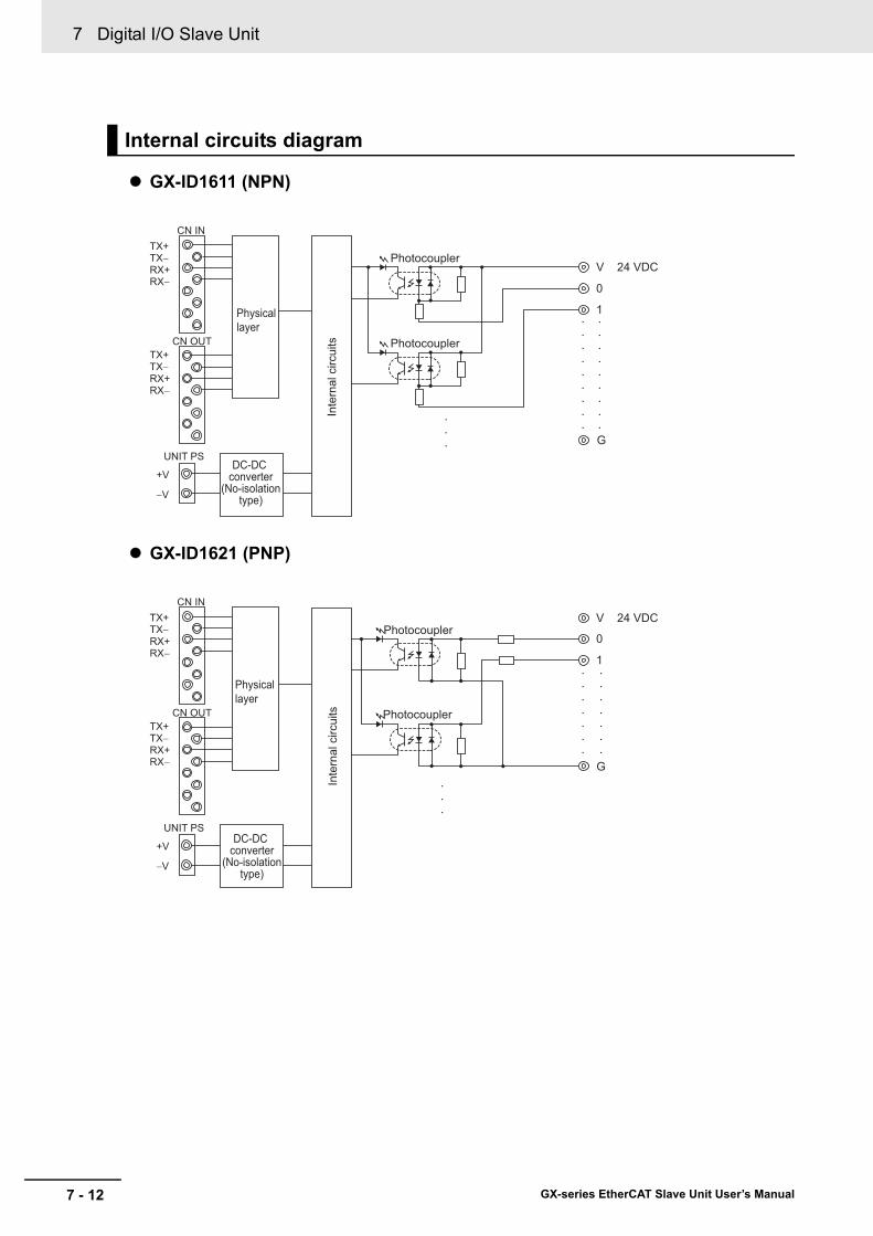
7 Digital I/O Slave Unit
7 - 12 GX-series EtherCAT Slave Unit User’s Manual
GX-ID1611 (NPN)
GX-ID1621 (PNP)
Internal circuits diagram
V 24 VDC
0
1
G
Photocoupler
PhotocouplerIn
tern
al c
ircui
ts
TX+
•
•
•
•
•
•
•
•
•
•
•
•
•
•
•
•
•
••
•
•
Physical layer
DC-DC converter
(No-isolationtype)
TX−RX+RX−
TX+TX−RX+RX−
CN IN
CN OUT
UNIT PS
+V
−V
V 24 VDC
0
1
G
•
•
•
•
•
•
•
•
•
•
•
•
•
•
•
•
•
Photocoupler
Photocoupler
Inte
rnal
circ
uits
TX+
Physical layer
DC-DC converter
(No-isolationtype)
TX−RX+RX−
TX+TX−RX+RX−
CN IN
CN OUT
UNIT PS
+V
−V
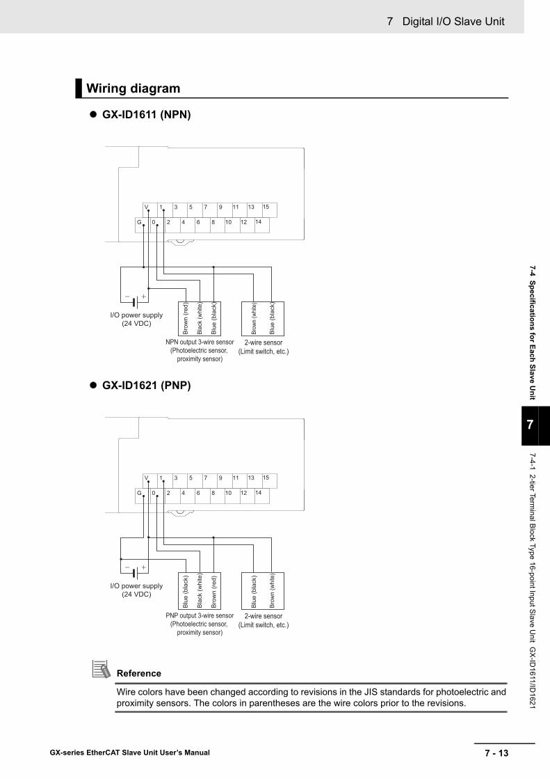
7 - 13
7 Digital I/O Slave Unit
GX-series EtherCAT Slave Unit User’s Manual
7-4 Specifications for Each Slave Unit
7
7-4-1 2-tier Terminal B
lock Type 16-point Input Slave U
nit GX
-ID1611/ID
1621
GX-ID1611 (NPN)
GX-ID1621 (PNP)
Reference
Wire colors have been changed according to revisions in the JIS standards for photoelectric and proximity sensors. The colors in parentheses are the wire colors prior to the revisions.
Wiring diagram
I/O power supply(24 VDC)
NPN output 3-wire sensor(Photoelectric sensor,
proximity sensor)
2-wire sensor(Limit switch, etc.)
Blu
e (b
lack
)
Blac
k (w
hite
)
Brow
n (w
hite)
Blu
e (b
lack
)
Bro
wn
(red
)
V 1 3 5 7 9 11 13 15
G 0 2 4 6 8 10 12 14
I/O power supply(24 VDC)
PNP output 3-wire sensor(Photoelectric sensor,
proximity sensor)
2-wire sensor(Limit switch, etc.)
Bro
wn
(red
)
Blac
k (w
hite
)
Blu
e (b
lack
)
Brow
n (w
hite
)
Blu
e (b
lack
)
V 1 3 5 7 9 11 13 15
G 0 2 4 6 8 10 12 14
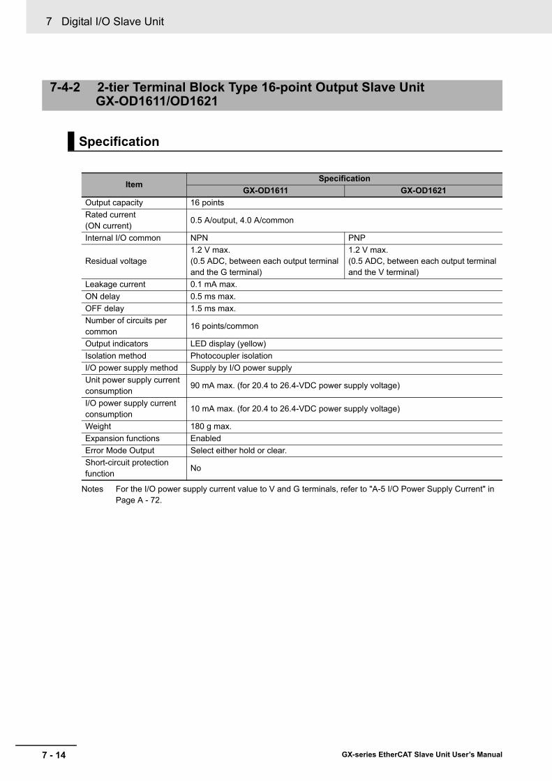
7 Digital I/O Slave Unit
7 - 14 GX-series EtherCAT Slave Unit User’s Manual
Notes For the I/O power supply current value to V and G terminals, refer to "A-5 I/O Power Supply Current" in Page A - 72.
7-4-2 2-tier Terminal Block Type 16-point Output Slave Unit GX-OD1611/OD1621
Specification
ItemSpecification
GX-OD1611 GX-OD1621Output capacity 16 pointsRated current (ON current)
0.5 A/output, 4.0 A/common
Internal I/O common NPN PNP
Residual voltage1.2 V max.(0.5 ADC, between each output terminal and the G terminal)
1.2 V max.(0.5 ADC, between each output terminal and the V terminal)
Leakage current 0.1 mA max.ON delay 0.5 ms max.OFF delay 1.5 ms max.Number of circuits per common
16 points/common
Output indicators LED display (yellow)Isolation method Photocoupler isolationI/O power supply method Supply by I/O power supplyUnit power supply current consumption
90 mA max. (for 20.4 to 26.4-VDC power supply voltage)
I/O power supply current consumption
10 mA max. (for 20.4 to 26.4-VDC power supply voltage)
Weight 180 g max.Expansion functions EnabledError Mode Output Select either hold or clear.Short-circuit protection function
No

7 - 15
7 Digital I/O Slave Unit
GX-series EtherCAT Slave Unit User’s Manual
7-4 Specifications for Each Slave Unit
7
7-4-2 2-tier Terminal B
lock Type 16-point Output S
lave Unit G
X-O
D1611/O
D1621
Terminal arrangement diagram
Names and functions
No. Name Function(1) Communications connectors
Refer to "6-3 Specifications of Common Areas" in Page 6 - 4.(2) Unit power supply connector(3) Status indicators(4) Node Address setting Switches
(5) Output indicators (0 to 15)Indicates the state of an output contact (ON/OFF).
Not lit: Contact OFF (output OFF state)Lit in yellow: Contact ON (output ON state)
(6) Terminal blockConnects external devices and the I/O power supply.
V, G: I/O power supply terminals0 to 15: Output terminals
(7) DIN track mounting hook Fixes a Slave Unit to a DIN track.
(5)
(1)
(6)
(2)
(3) (4)
(7)
10 to 18
1 to 9
V 1 3 5 7 9
G 0 2 4 6 8 10 12 14
11 13 15
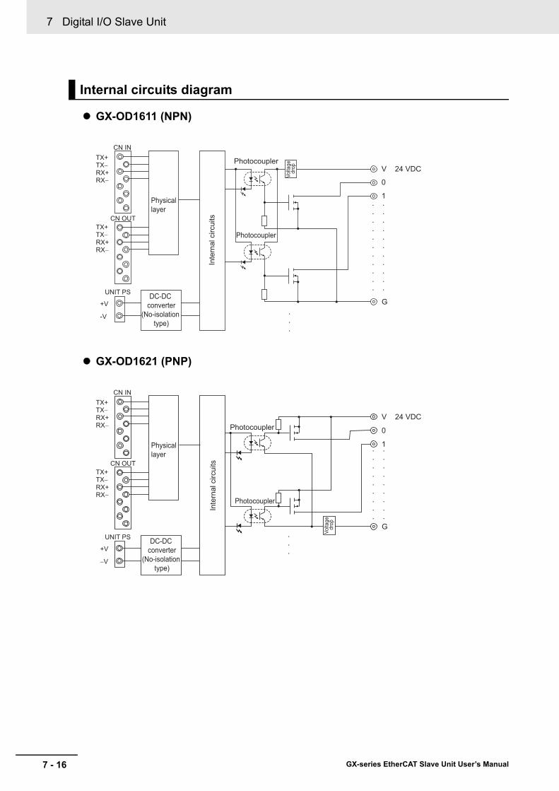
7 Digital I/O Slave Unit
7 - 16 GX-series EtherCAT Slave Unit User’s Manual
GX-OD1611 (NPN)
GX-OD1621 (PNP)
Internal circuits diagram
0
1
G
V 24 VDC
•
•
•
•
•
•
•
•
•
•
•
•
•
•
•
•
•
•
•
•
•
•
•
•
•
Photocoupler
Inte
rnal
circ
uits
Photocoupler
Volta
ge d
rop
TX+
Physical layer
DC-DC converter
(No-isolation type)
TX−RX+RX−
TX+TX−RX+RX−
CN IN
CN OUT
UNIT PS
+V
-V
0
1
G
V 24 VDCPhotocoupler
Photocoupler
Volta
ge d
rop
•
•
•
•
•
•
•
•
•
•
•
•
•
•
•
•
•
•
•
•
•
TX+
Physical layer
DC-DC converter
(No-isolation type)
TX−RX+RX−
TX+TX−RX+RX−
CN IN
CN OUT
UNIT PS
+V
−V
Inte
rnal
circ
uits

7 - 17
7 Digital I/O Slave Unit
GX-series EtherCAT Slave Unit User’s Manual
7-4 Specifications for Each Slave Unit
7
7-4-2 2-tier Terminal B
lock Type 16-point Output S
lave Unit G
X-O
D1611/O
D1621
GX-OD1611 (NPN)
GX-OD1621 (PNP)
Precautions for Correct Use
When using an inductive load, such as a solenoid valve, either use a built-in diode for absorbing the counterelectromotive force or install an external diode. (Refer to "A-4 Wiring External Output Signal Lines" in Page A - 71.)
Wiring diagram
I/O power supply(24 VDC)
Solenoid valve, etc. Solenoid valve, etc.
V 1 3 5 7 9 11 13 15
G 0 2 4 6 8 10 12 14
I/O power supply(24 VDC)
Solenoid valve, etc. Solenoid valve, etc.
V 1 3 5 7 9 11 13 15
G 0 2 4 6 8 10 12 14
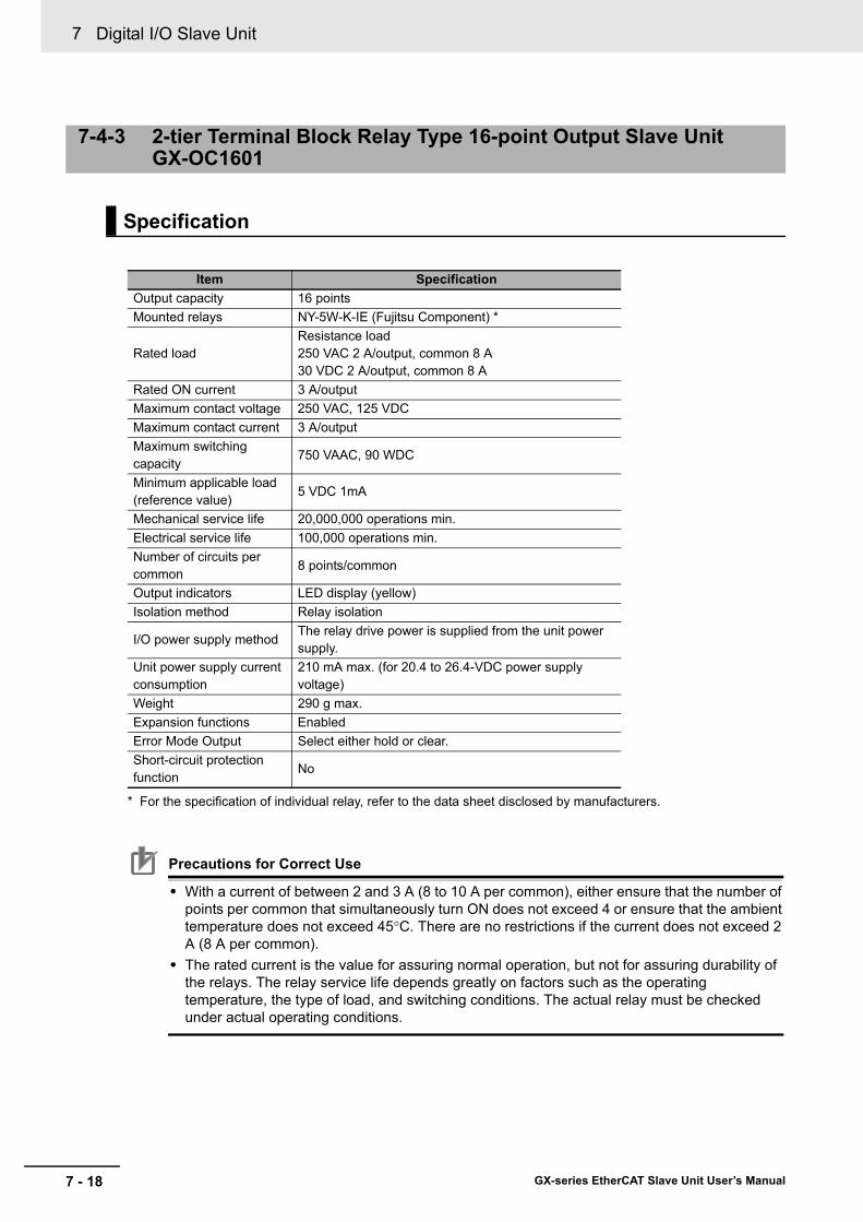
7 Digital I/O Slave Unit
7 - 18 GX-series EtherCAT Slave Unit User’s Manual
* For the specification of individual relay, refer to the data sheet disclosed by manufacturers.
Precautions for Correct Use
• With a current of between 2 and 3 A (8 to 10 A per common), either ensure that the number of points per common that simultaneously turn ON does not exceed 4 or ensure that the ambient temperature does not exceed 45°C. There are no restrictions if the current does not exceed 2 A (8 A per common).
• The rated current is the value for assuring normal operation, but not for assuring durability of the relays. The relay service life depends greatly on factors such as the operating temperature, the type of load, and switching conditions. The actual relay must be checked under actual operating conditions.
7-4-3 2-tier Terminal Block Relay Type 16-point Output Slave UnitGX-OC1601
Specification
Item SpecificationOutput capacity 16 pointsMounted relays NY-5W-K-IE (Fujitsu Component) *
Rated loadResistance load250 VAC 2 A/output, common 8 A30 VDC 2 A/output, common 8 A
Rated ON current 3 A/outputMaximum contact voltage 250 VAC, 125 VDCMaximum contact current 3 A/outputMaximum switching capacity
750 VAAC, 90 WDC
Minimum applicable load (reference value)
5 VDC 1mA
Mechanical service life 20,000,000 operations min.Electrical service life 100,000 operations min.Number of circuits per common
8 points/common
Output indicators LED display (yellow)Isolation method Relay isolation
I/O power supply methodThe relay drive power is supplied from the unit power supply.
Unit power supply current consumption
210 mA max. (for 20.4 to 26.4-VDC power supply voltage)
Weight 290 g max.Expansion functions EnabledError Mode Output Select either hold or clear.Short-circuit protection function
No
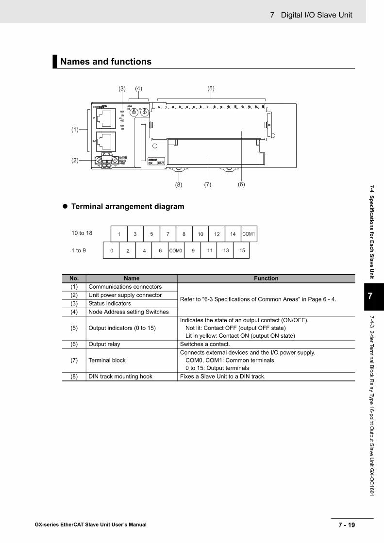
7 - 19
7 Digital I/O Slave Unit
GX-series EtherCAT Slave Unit User’s Manual
7-4 Specifications for Each Slave Unit
7
7-4-3 2-tier Terminal B
lock Relay Type 16-point O
utput Slave U
nit GX
-OC
1601
Terminal arrangement diagram
Names and functions
No. Name Function(1) Communications connectors
Refer to "6-3 Specifications of Common Areas" in Page 6 - 4.(2) Unit power supply connector(3) Status indicators(4) Node Address setting Switches
(5) Output indicators (0 to 15)Indicates the state of an output contact (ON/OFF).
Not lit: Contact OFF (output OFF state)Lit in yellow: Contact ON (output ON state)
(6) Output relay Switches a contact.
(7) Terminal blockConnects external devices and the I/O power supply.
COM0, COM1: Common terminals0 to 15: Output terminals
(8) DIN track mounting hook Fixes a Slave Unit to a DIN track.
(3) (4) (5)
(8)
(1)
(7)
(2)
(6)
10 to 18
1 to 9
10 12 14 COM11 3 5 7 8
0 2 4 6 9 11 13 15COM0
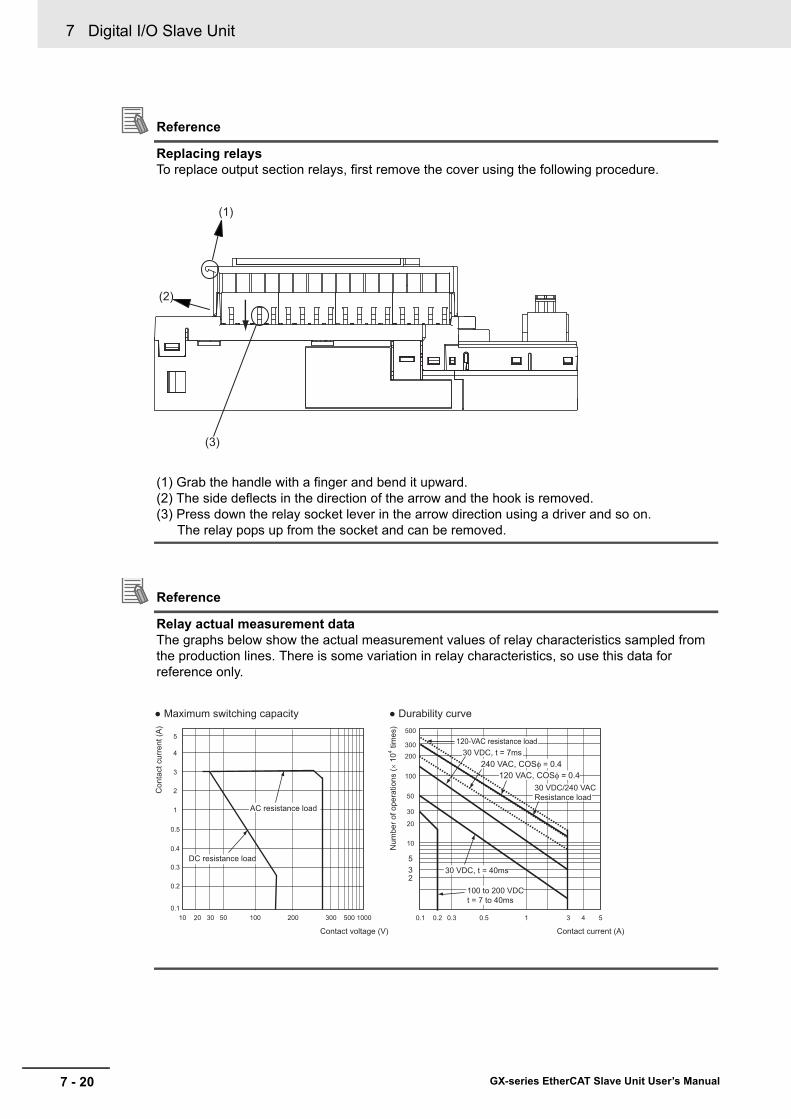
7 Digital I/O Slave Unit
7 - 20 GX-series EtherCAT Slave Unit User’s Manual
Reference
Replacing relaysTo replace output section relays, first remove the cover using the following procedure.
(1) Grab the handle with a finger and bend it upward.(2) The side deflects in the direction of the arrow and the hook is removed.(3) Press down the relay socket lever in the arrow direction using a driver and so on.
The relay pops up from the socket and can be removed.
Reference
Relay actual measurement dataThe graphs below show the actual measurement values of relay characteristics sampled from the production lines. There is some variation in relay characteristics, so use this data for reference only.
(1)
(2)
(3)
30 VDC, t = 40ms
30 VDC/240 VACResistance load
240 VAC, COSφ = 0.4
0.1 0.3 0.5 1 3 5
235
10
20
30
50
100
200
300
500
Contact current (A)
● Durability curve
Num
ber o
f ope
ratio
ns (×
104 ti
mes
)
DC resistance load
AC resistance load
Con
tact
cur
rent
(A)
0.1
0.3
0.5
1
3
5
Contact voltage (V)
10 20 200 500 1000
● Maximum switching capacity
30 30050 100
0.2
2
0.2 4
100 to 200 VDCt = 7 to 40ms
120-VAC resistance load
120 VAC, COSφ = 0.4
30 VDC, t = 7ms
0.4
4

7 - 21
7 Digital I/O Slave Unit
GX-series EtherCAT Slave Unit User’s Manual
7-4 Specifications for Each Slave Unit
7
7-4-3 2-tier Terminal B
lock Relay Type 16-point O
utput Slave U
nit GX
-OC
1601
Internal circuits diagram
Wiring diagram
Inte
rnal
circ
uits
8
9
COM1
Photocoupler
Photocoupler
DC-DC converter for relay drive(No-isolation type)
0
1
COM0
Photocoupler
PhotocouplerNY-5W-K-IE
5 VDC
TX+
Physical layer
DC-DC converter
(No-isolation type)
TX−RX+RX−
TX+TX−RX+RX−
CN IN
CN OUT
UNIT PS
+V
−V
•
•
•
•
•
•
•
•
•
•
•
•
•
•
•
•
•
•
•
•
•
NY-5W-K-IE5 VDC
AC power supply(DC power supply is also allowed)
Load
Load Load
LoadLoad
Load
Load
Load
Load
LoadLoad
Load
Load
Load
Load
Load
10 12 14 COM11 3 5 7 8
0 2 4 6 COM0 11 13 159
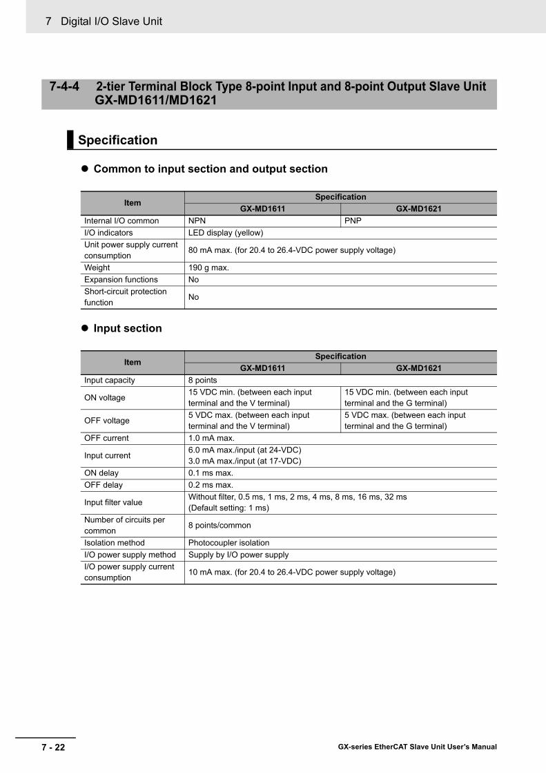
7 Digital I/O Slave Unit
7 - 22 GX-series EtherCAT Slave Unit User’s Manual
Common to input section and output section
Input section
7-4-4 2-tier Terminal Block Type 8-point Input and 8-point Output Slave Unit GX-MD1611/MD1621
Specification
ItemSpecification
GX-MD1611 GX-MD1621Internal I/O common NPN PNPI/O indicators LED display (yellow)Unit power supply current consumption
80 mA max. (for 20.4 to 26.4-VDC power supply voltage)
Weight 190 g max.Expansion functions NoShort-circuit protection function
No
ItemSpecification
GX-MD1611 GX-MD1621Input capacity 8 points
ON voltage15 VDC min. (between each input terminal and the V terminal)
15 VDC min. (between each input terminal and the G terminal)
OFF voltage5 VDC max. (between each input terminal and the V terminal)
5 VDC max. (between each input terminal and the G terminal)
OFF current 1.0 mA max.
Input current6.0 mA max./input (at 24-VDC)3.0 mA max./input (at 17-VDC)
ON delay 0.1 ms max.OFF delay 0.2 ms max.
Input filter valueWithout filter, 0.5 ms, 1 ms, 2 ms, 4 ms, 8 ms, 16 ms, 32 ms(Default setting: 1 ms)
Number of circuits per common
8 points/common
Isolation method Photocoupler isolationI/O power supply method Supply by I/O power supplyI/O power supply current consumption
10 mA max. (for 20.4 to 26.4-VDC power supply voltage)

7 - 23
7 Digital I/O Slave Unit
GX-series EtherCAT Slave Unit User’s Manual
7-4 Specifications for Each Slave Unit
7
7-4-4 2-tier Terminal B
lock Type 8-point Input and 8-point Output S
lave Unit
GX
-MD
1611/MD
1621
Output section
Notes For the I/O power supply current value to V and G terminals ,refer to "A-5 I/O Power Supply Current" in Page A - 72.
ItemSpecification
GX-MD1611 GX-MD1621Output capacity 8 pointsRated output current 0.5 A/output, 2.0 A/common
Residual voltage1.2 V max.(0.5 ADC, between each output terminal and the G terminal)
1.2 V max.(0.5 ADC, between each output terminal and the V terminal)
Leakage current 0.1 mA max.ON delay 0.5 ms max.OFF delay 1.5 ms max.Number of circuits per common
8 points/common
Isolation method Photocoupler isolationI/O power supply method Supply by I/O power supplyI/O power supply current consumption
10 mA max. (for 20.4 to 26.4-VDC power supply voltage)
Error Mode Output Select either hold or clear.

7 Digital I/O Slave Unit
7 - 24 GX-series EtherCAT Slave Unit User’s Manual
Terminal arrangement diagram
Names and functions
No. Name Function(1) Communications connectors
Refer to "6-3 Specifications of Common Areas" in Page 6 - 4.(2) Unit power supply connector(3) Status indicators(4) Node Address setting Switches
(5) Input indicators (0 to 7)Indicates the state of an input contact (ON/OFF).
Not lit: Contact OFF (input OFF state)Lit in yellow: Contact ON (input ON state)
(6) Output indicators (0 to 7)Indicates the state of an output contact (ON/OFF).
Not lit: Contact OFF (output OFF state)Lit in yellow: Contact ON (output ON state)
(7) Terminal block
Connects external devices and the I/O power supply.<Left side>
V1, G1: Input side I/O power supply terminals0 to 7: Input terminals
<Right side>V2, G2: Output side I/O power supply terminals0 to 7: Output terminals
(8) DIN track mounting hook Fixes a Slave Unit to a DIN track.
(5)
(1)
(2)
(3) (4) (6)
(8) (7)
NC12 to 22
1 to 11
Left side (input) Right side (output)
V1 1 3 5 7 V2 1 3 5 7
NCG1 0 2 4 6 G2 0 2 4 6
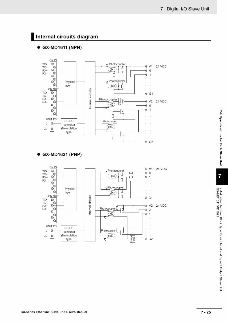
7 - 25
7 Digital I/O Slave Unit
GX-series EtherCAT Slave Unit User’s Manual
7-4 Specifications for Each Slave Unit
7
7-4-4 2-tier Terminal B
lock Type 8-point Input and 8-point Output S
lave Unit
GX
-MD
1611/MD
1621
GX-MD1611 (NPN)
GX-MD1621 (PNP)
Internal circuits diagram
Photocoupler
01
G2
Photocoupler
V2 24 VDC
Photocoupler
Photocoupler
V1 24 VDC01
G1
Volta
ge
drop
•
•
•
•
•
•
•
•
•
•
•
•
•
•
•
•
•
•
•
•
•
•
•
•
Inte
rnal
circ
uits
TX+
Physical layer
DC-DC converter
(No-isolation type)
TX−RX+RX−
TX+TX−RX+RX−
CN IN
CN OUT
UNIT PS
+V
−V
Photocoupler 01
G2
Photocoupler
V2 24 VDC
Photocoupler
Photocoupler
V1 24 VDC01
G1
•
•
•
•
•
•
•
•
•
•
•
•
•
•
•
•
•
•
•
•
•
•
TX+
Physical layer
DC-DC converter
(No-isolation type)
TX−RX+RX−
TX+TX−RX+RX−
CN IN
CN OUT
UNIT PS
+V
−V
Volta
ge
drop
Inte
rnal
circ
uits

7 Digital I/O Slave Unit
7 - 26 GX-series EtherCAT Slave Unit User’s Manual
GX-MD1611 (NPN)
GX-MD1621 (PNP)
Wiring diagram
I/O power supply(24 VDC)
Solenoid valve, etc. Solenoid valve, etc.
I/O power supply(24 VDC)
NPN output 3-wire sensor(Photoelectric sensor,
proximity sensor)
2-wire sensor(Limit switch, etc.)
Blu
e (b
lack
)
Blac
k (w
hite
)
Brow
n (w
hite
)
Blu
e (b
lack
)
Bro
wn
(red
)
V1 NC
G1 NC
V2
G2
1 3 5 7 1 3 5 7
0 2 4 6 0 2 4 6
I/O power supply(24 VDC)
Solenoid valve, etc. Solenoid valve, etc.
I/O power supply(24 VDC)
V1 NC
G1 NC
V2
G2
1 3 5 7 1 3 5 7
0 2 4 6 0 2 4 6
PNP output 3-wire sensor(Photoelectric sensor,
proximity sensor)
2-wire sensor(Limit switch, etc.)
Bro
wn
(red
)
Bla
ck (w
hite
)
Blu
e (b
lack
)
Brow
n (w
hite
)
Blu
e (b
lack
)
7 - 27
7 Digital I/O Slave Unit
GX-series EtherCAT Slave Unit User’s Manual
7-4 Specifications for Each Slave Unit
7
7-4-4 2-tier Terminal B
lock Type 8-point Input and 8-point Output S
lave Unit
GX
-MD
1611/MD
1621
Precautions for Correct Use
• The V1 and V2 terminals as well as the G1 and G2 terminals of the I/O power supply are not connected internally. Supply power separately for V1-G1 and V2-G2.
• When using an inductive load, such as a solenoid valve, either use a built-in diode for absorbing the counterelectromotive force or install an external diode. (Refer to "A-4 Wiring External Output Signal Lines" in Page A - 71.)
• Do not wire NC terminals.
Reference
Wire colors have been changed according to revisions in the JIS standards for photoelectric and proximity sensors. The colors in parentheses are the wire colors prior to the revisions.

7 Digital I/O Slave Unit
7 - 28 GX-series EtherCAT Slave Unit User’s Manual
Notes For the I/O power supply current value to V and G terminals ,refer to "A-5 I/O Power Supply Current" in Page A - 72.
7-4-5 3-tier Terminal Block Type 16-point Input Slave UnitGX-ID1612/ID1622
Specification
ItemSpecification
GX-ID1612 GX-ID1622Input capacity 16 pointsInternal I/O common NPN PNP
ON voltage15 VDC min. (between each input terminal and the V terminal)
15 VDC min. (between each input terminal and the G terminal)
OFF voltage5 VDC max. (between each input terminal and the V terminal)
5 VDC max. (between each input terminal and the G terminal)
OFF current 1.0 mA max.
Input current6.0 mA max./input (at 24-VDC)3.0 mA max./input (at 17-VDC)
ON delay 0.1 ms max.OFF delay 0.2 ms max.
Input filter valueWithout filter, 0.5 ms, 1 ms, 2 ms, 4 ms, 8 ms, 16 ms, 32 ms(Default setting: 1 ms)
Number of circuits per common
8 points/common
Input indicators LED display (yellow)Isolation method Photocoupler isolationI/O power supply method Supply by I/O power supplyInput device supply current
100 mA/point
Unit power supply current consumption
90 mA max. (for 20.4 to 26.4-VDC power supply voltage)
I/O power supply current consumption
10 mA max. (for 20.4 to 26.4-VDC power supply voltage)
Weight 370 g max.Expansion functions NoShort-circuit protection function
No
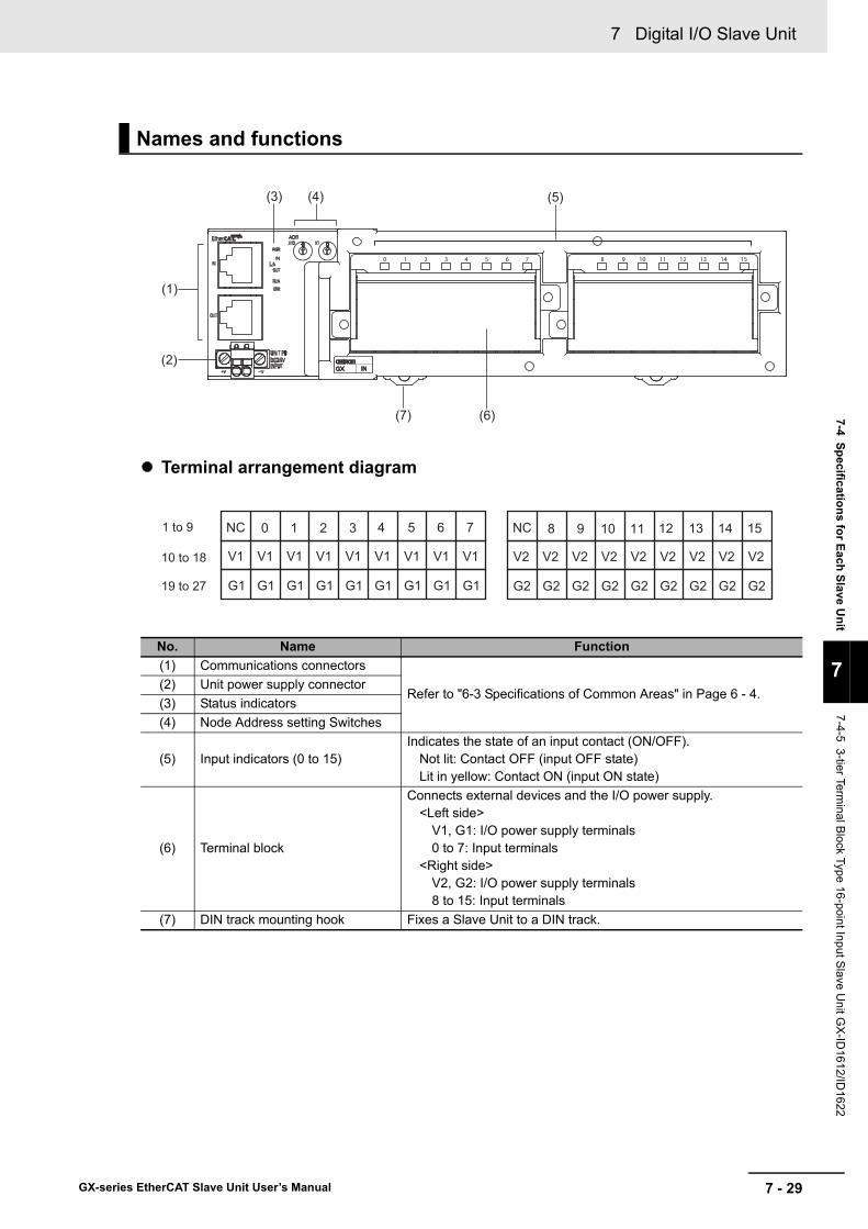
7 - 29
7 Digital I/O Slave Unit
GX-series EtherCAT Slave Unit User’s Manual
7-4 Specifications for Each Slave Unit
7
7-4-5 3-tier Terminal B
lock Type 16-point Input Slave U
nit GX
-ID1612/ID
1622
Terminal arrangement diagram
Names and functions
No. Name Function(1) Communications connectors
Refer to "6-3 Specifications of Common Areas" in Page 6 - 4.(2) Unit power supply connector(3) Status indicators(4) Node Address setting Switches
(5) Input indicators (0 to 15)Indicates the state of an input contact (ON/OFF).
Not lit: Contact OFF (input OFF state)Lit in yellow: Contact ON (input ON state)
(6) Terminal block
Connects external devices and the I/O power supply.<Left side>
V1, G1: I/O power supply terminals0 to 7: Input terminals
<Right side>V2, G2: I/O power supply terminals8 to 15: Input terminals
(7) DIN track mounting hook Fixes a Slave Unit to a DIN track.
(5)
(1)
(6)
(2)
(3) (4)
(7)
10 to 18
1 to 9
19 to 27
NC 0 1 2 3 4 5 6 7
V1 V1 V1 V1 V1 V1 V1 V1
G1 G1 G1 G1 G1 G1 G1 G1
V1
G1
NC 8 9 10 11 12 13 14 15
V2 V2 V2 V2 V2 V2 V2 V2
G2 G2 G2 G2 G2 G2 G2 G2
V2
G2

7 Digital I/O Slave Unit
7 - 30 GX-series EtherCAT Slave Unit User’s Manual
GX-ID1612 (NPN)
GX-ID1622 (PNP)
Internal circuits diagram
V1 24 VDC
G1
V1
0 to 7
G1
V2 24 VDC
G2
V2
8 to 15
G2
Internal circuits
Photocoupler
Photocoupler
Inpu
t circ
uit
Inpu
t circ
uit
TX+
•••
Physical layer
DC-DC converter
(No-isolation type)
TX−RX+RX−
TX+TX−RX+RX−
CN IN
CN OUT
UNIT PS
+V
−V
•••
•••
•••
G1
V1 24 VDC
G1
0 to 7
V1
G2
V2 24 VDC
G2
8 to 15
V2
Internal circuits
Photocoupler
Photocoupler
TX+
Physical layer
DC-DC converter
(No-isolation type)
TX−RX+RX-
TX+TX−RX+RX−
CN IN
CN OUT
UNIT PS
+V
−V
•••
•••
•••
•••
Inpu
t circ
uit
Inpu
t circ
uit

7 - 31
7 Digital I/O Slave Unit
GX-series EtherCAT Slave Unit User’s Manual
7-4 Specifications for Each Slave Unit
7
7-4-5 3-tier Terminal B
lock Type 16-point Input Slave U
nit GX
-ID1612/ID
1622
GX-ID1612 (NPN)
GX-ID1622 (PNP)
Wiring diagram
NPN output 3-wire sensor(Photoelectric sensor,
proximity sensor)
2-wire sensor(Limit switch, etc.)
Blu
e (b
lack
)
Blac
k (w
hite
)
Bro
wn
(red
)
Brow
n (w
hite
)
Blu
e (b
lack
)NC NC 8 90 1 2 3 4 5 6 7
V1 V1 V1 V1 V1 V1 V1 V1
G1 G1 G1 G1 G1 G1 G1 G1
V1
G1
10 11 12 13 14 15
V2 V2 V2 V2 V2 V2 V2 V2 V2
G2 G2 G2 G2 G2 G2 G2 G2 G2
I/O power supply(24 VDC)
PNP output 3-wire sensor(Photoelectric sensor,
proximity sensor)
2-wire sensor(Limit switch, etc.)
Blu
e (b
lack
)
Blac
k (w
hite
)
Bro
wn
(red
)
Brow
n (w
hite
)
Blu
e (b
lack
)
NC NC 8 90 1 2 3 4 5 6 7
V1 V1 V1 V1 V1 V1 V1 V1
G1 G1 G1 G1 G1 G1 G1 G1
V1
G1
10 11 12 13 14 15
V2 V2 V2 V2 V2 V2 V2 V2 V2
G2 G2 G2 G2 G2 G2 G2 G2 G2
I/O power supply(24 VDC)

7 Digital I/O Slave Unit
7 - 32 GX-series EtherCAT Slave Unit User’s Manual
Precautions for Correct Use
• The V1 and V2 terminals as well as the G1 and G2 terminals of the I/O power supply are not connected internally. Supply power separately for V1-G1 and V2-G2.
• Do not wire NC terminals.
Reference
Wire colors have been changed according to revisions in the JIS standards for photoelectric and proximity sensors. The colors in parentheses are the wire colors prior to the revisions.

7 - 33
7 Digital I/O Slave Unit
GX-series EtherCAT Slave Unit User’s Manual
7-4 Specifications for Each Slave Unit
7
7-4-6 3-tier Terminal B
lock Type 16-point Output S
lave Unit G
X-O
D1612/O
D1622
Notes For the I/O power supply current value to V and G terminals ,refer to "A-5 I/O Power Supply Current" in Page A - 72.
7-4-6 3-tier Terminal Block Type 16-point Output Slave Unit GX-OD1612/OD1622
Specification
ItemSpecification
GX-OD1612 GX-OD1622Output capacity 16 pointsRated current (ON current)
0.5 A/output, 4.0 A/common
Internal I/O common NPN PNP
Residual voltage1.2 V max.(0.5 ADC, between each output terminal and the G terminal)
1.2 V max.(0.5 ADC, between each output terminal and the V terminal)
Leakage current 0.1 mA max.ON delay 0.5 ms max.OFF delay 1.5 ms max.Number of circuits per common
8 points/common
Output indicators LED display (yellow)Isolation method Photocoupler isolationI/O power supply method Supply by I/O power supplyOutput device supply current
100 mA/point
Unit power supply current consumption
90 mA max. (for 20.4 to 26.4-VDC power supply voltage)
I/O power supply current consumption
10 mA max. (for 20.4 to 26.4-VDC power supply voltage)
Weight 370 g max.Expansion functions NoError Mode Output Select either hold or clear.Short-circuit protection function
No
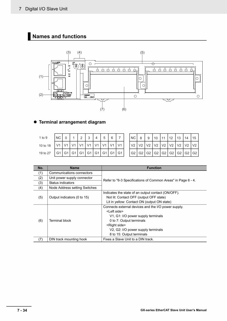
7 Digital I/O Slave Unit
7 - 34 GX-series EtherCAT Slave Unit User’s Manual
Terminal arrangement diagram
Names and functions
No. Name Function(1) Communications connectors
Refer to "6-3 Specifications of Common Areas" in Page 6 - 4.(2) Unit power supply connector(3) Status indicators(4) Node Address setting Switches
(5) Output indicators (0 to 15)Indicates the state of an output contact (ON/OFF).
Not lit: Contact OFF (output OFF state)Lit in yellow: Contact ON (output ON state)
(6) Terminal block
Connects external devices and the I/O power supply.<Left side>
V1, G1: I/O power supply terminals0 to 7: Output terminals
<Right side>V2, G2: I/O power supply terminals8 to 15: Output terminals
(7) DIN track mounting hook Fixes a Slave Unit to a DIN track.
(5)
(1)
(6)
(2)
(3) (4)
(7)
10 to 18
1 to 9
19 to 27
NC 0 1 2 3 4 5 6 7
V1 V1 V1 V1 V1 V1 V1 V1
G1 G1 G1 G1 G1 G1 G1 G1
V1
G1
NC 8 9 10 11 12 13 14 15
V2 V2 V2 V2 V2 V2 V2 V2
G2 G2 G2 G2 G2 G2 G2 G2
V2
G2
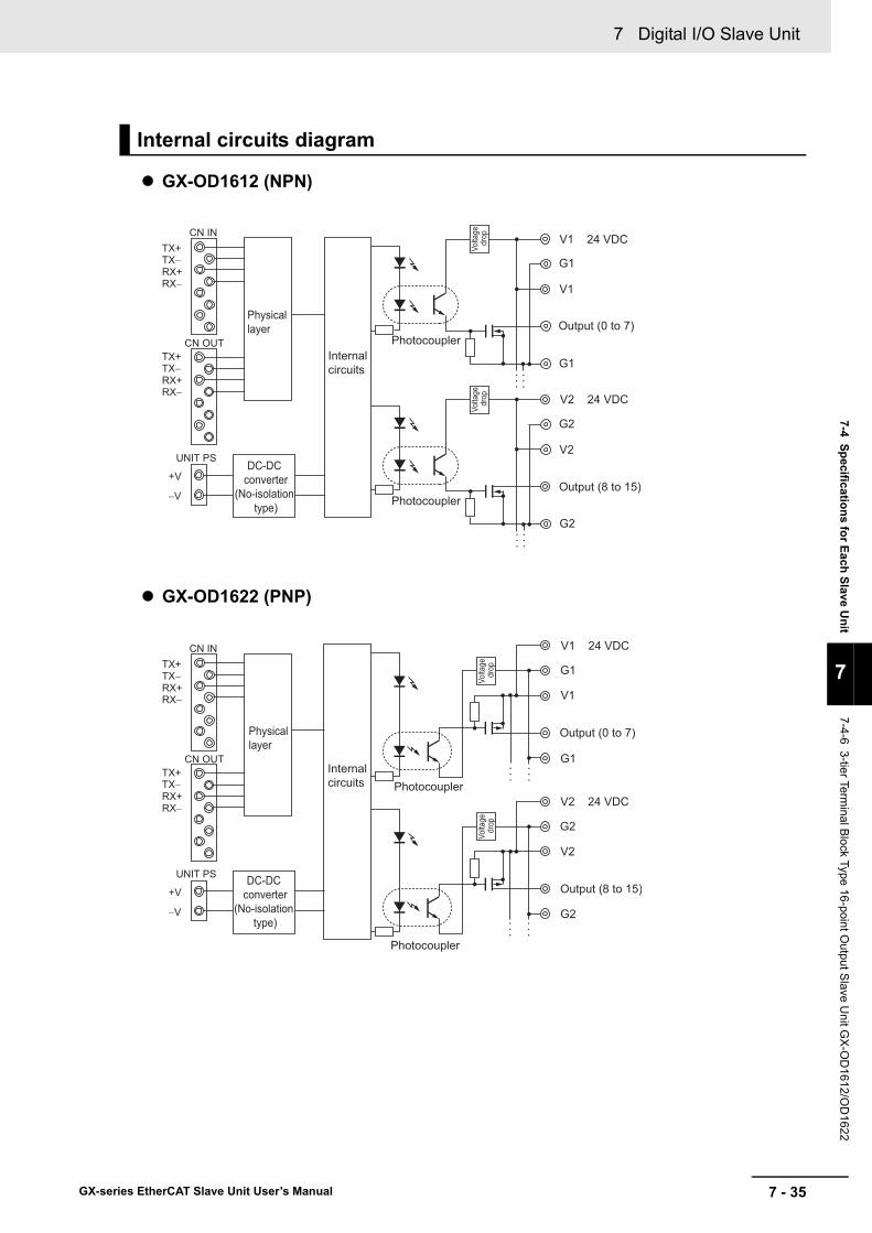
7 - 35
7 Digital I/O Slave Unit
GX-series EtherCAT Slave Unit User’s Manual
7-4 Specifications for Each Slave Unit
7
7-4-6 3-tier Terminal B
lock Type 16-point Output S
lave Unit G
X-O
D1612/O
D1622
GX-OD1612 (NPN)
GX-OD1622 (PNP)
Internal circuits diagram
V1 24 VDC
G1
V1
G1
V2 24 VDC
G2
V2
G2
Internal circuits
Photocoupler
Photocoupler
Output (0 to 7)
Output (8 to 15)Vo
ltage
dr
opVo
ltage
dr
op
TX+
•••
•••
•••
•••
Physical layer
DC-DC converter
(No-isolation type)
TX−RX+RX−
TX+TX−RX+RX−
CN IN
CN OUT
UNIT PS
+V
−V
V1 24 VDC
G1
V1
G1
V2 24 VDC
G2
V2
G2
Internal circuits Photocoupler
Photocoupler
Output (0 to 7)
Output (8 to 15)
TX+
Physical layer
DC-DC converter
(No-isolation type)
TX−RX+RX−
TX+TX−RX+RX−
CN IN
CN OUT
UNIT PS
+V
−V
Volta
ge
drop
Volta
ge
drop
•••
•••
•••
•••

7 Digital I/O Slave Unit
7 - 36 GX-series EtherCAT Slave Unit User’s Manual
GX-OD1612 (NPN)
GX-OD1622 (PNP)
Wiring diagram
Solenoid valve, etc. NPN input 3-wire external device
(Emitter of photoelectric sensor)
Blue
(blac
k)
Pink
(whit
e)
Brow
n (re
d)
NC NC 8 90 1 2 3 4 5 6 7
V1 V1 V1 V1 V1 V1 V1 V1
G1 G1 G1 G1 G1 G1 G1 G1
V1
G1
10 11 12 13 14 15
V2 V2 V2 V2 V2 V2 V2 V2 V2
G2 G2 G2 G2 G2 G2 G2 G2 G2
I/O power supply(24 VDC)
Solenoid valve, etc. PNP input 3-wire external device
(Emitter of photoelectric sensor)
Blue
(blac
k)
Pink
(whit
e)
Brow
n (re
d)
NC NC 8 90 1 2 3 4 5 6 7
V1 V1 V1 V1 V1 V1 V1 V1
G1 G1 G1 G1 G1 G1 G1 G1
V1
G1
10 11 12 13 14 15
V2 V2 V2 V2 V2 V2 V2 V2 V2
G2 G2 G2 G2 G2 G2 G2 G2 G2
I/O power supply(24 VDC)
7 - 37
7 Digital I/O Slave Unit
GX-series EtherCAT Slave Unit User’s Manual
7-4 Specifications for Each Slave Unit
7
7-4-6 3-tier Terminal B
lock Type 16-point Output S
lave Unit G
X-O
D1612/O
D1622
Precautions for Correct Use
• The V1 and V2 terminals as well as the G1 and G2 terminals of the I/O power supply are not connected internally. Supply power separately for V1-G1 and V2-G2.
• Use a maximum current of 500 mA for each V1, V2, G1, and G2 terminals aside from the I/O power supply terminals.
• When using an inductive load, such as a solenoid valve, either use a built-in diode for absorbing the counterelectromotive force or install an external diode. (Refer to "A-4 Wiring External Output Signal Lines" in Page A - 71.)
• Do not wire NC terminals.
Reference
Wire colors have been changed according to revisions in the JIS standards for photoelectric and proximity sensors. The colors in parentheses are the wire colors prior to the revisions.
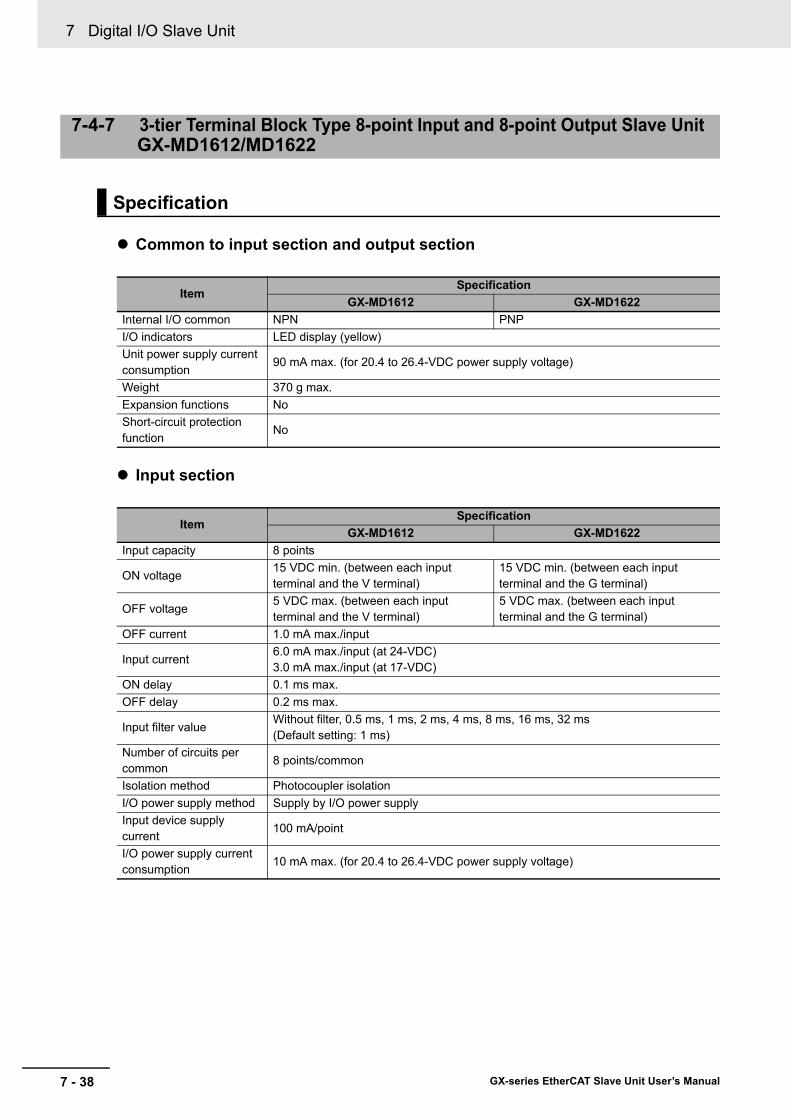
7 Digital I/O Slave Unit
7 - 38 GX-series EtherCAT Slave Unit User’s Manual
Common to input section and output section
Input section
7-4-7 3-tier Terminal Block Type 8-point Input and 8-point Output Slave Unit GX-MD1612/MD1622
Specification
ItemSpecification
GX-MD1612 GX-MD1622Internal I/O common NPN PNPI/O indicators LED display (yellow)Unit power supply current consumption
90 mA max. (for 20.4 to 26.4-VDC power supply voltage)
Weight 370 g max.Expansion functions NoShort-circuit protection function
No
ItemSpecification
GX-MD1612 GX-MD1622Input capacity 8 points
ON voltage15 VDC min. (between each input terminal and the V terminal)
15 VDC min. (between each input terminal and the G terminal)
OFF voltage5 VDC max. (between each input terminal and the V terminal)
5 VDC max. (between each input terminal and the G terminal)
OFF current 1.0 mA max./input
Input current6.0 mA max./input (at 24-VDC)3.0 mA max./input (at 17-VDC)
ON delay 0.1 ms max.OFF delay 0.2 ms max.
Input filter valueWithout filter, 0.5 ms, 1 ms, 2 ms, 4 ms, 8 ms, 16 ms, 32 ms(Default setting: 1 ms)
Number of circuits per common
8 points/common
Isolation method Photocoupler isolationI/O power supply method Supply by I/O power supplyInput device supply current
100 mA/point
I/O power supply current consumption
10 mA max. (for 20.4 to 26.4-VDC power supply voltage)
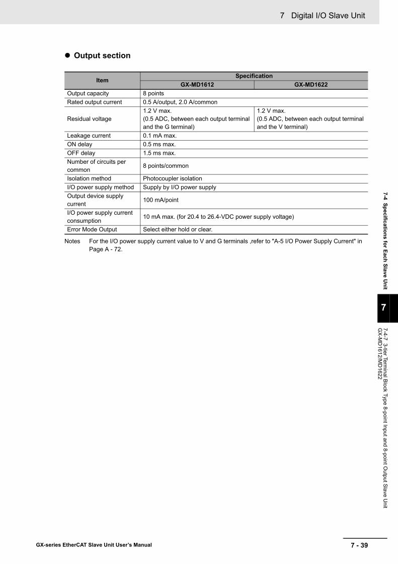
7 - 39
7 Digital I/O Slave Unit
GX-series EtherCAT Slave Unit User’s Manual
7-4 Specifications for Each Slave Unit
7
7-4-7 3-tier Terminal B
lock Type 8-point Input and 8-point Output S
lave Unit
GX
-MD
1612/MD
1622
Output section
Notes For the I/O power supply current value to V and G terminals ,refer to "A-5 I/O Power Supply Current" in Page A - 72.
ItemSpecification
GX-MD1612 GX-MD1622Output capacity 8 pointsRated output current 0.5 A/output, 2.0 A/common
Residual voltage1.2 V max.(0.5 ADC, between each output terminal and the G terminal)
1.2 V max.(0.5 ADC, between each output terminal and the V terminal)
Leakage current 0.1 mA max.ON delay 0.5 ms max.OFF delay 1.5 ms max.Number of circuits per common
8 points/common
Isolation method Photocoupler isolationI/O power supply method Supply by I/O power supplyOutput device supply current
100 mA/point
I/O power supply current consumption
10 mA max. (for 20.4 to 26.4-VDC power supply voltage)
Error Mode Output Select either hold or clear.

7 Digital I/O Slave Unit
7 - 40 GX-series EtherCAT Slave Unit User’s Manual
Terminal arrangement diagram
Names and functions
No. Name Function(1) Communications connectors
Refer to "6-3 Specifications of Common Areas" in Page 6 - 4.(2) Unit power supply connector(3) Status indicators(4) Node Address setting Switches
(5) Input indicators (0 to 7)Indicates the state of an input contact (ON/OFF).
Not lit: Contact OFF (input OFF state)Lit in yellow: Contact ON (input ON state)
(6) Output indicators (0 to 7)Indicates the state of an output contact (ON/OFF).
Not lit: Contact OFF (output OFF state)Lit in yellow: Contact ON (output ON state)
(7) Terminal block
Connects external devices and the I/O power supply.<Left side>
V1, G1: Input side I/O power supply terminals0 to 7: Input terminals
<Right side>V2, G2: Output side I/O power supply terminals0 to 7: Output terminals
(8) DIN track mounting hook Fixes a Slave Unit to a DIN track.
(5)
(1)
(7)
(2)
(3) (4) (6)
(8)
10 to 18
1 to 9
19 to 27
NC 0 1 2 3 4 5 6 7
V1 V1 V1 V1 V1 V1 V1 V1
G1 G1 G1 G1 G1 G1 G1 G1
V1
G1
NC 0 1 2 3 4 5 6 7
V2 V2 V2 V2 V2 V2 V2 V2
G2 G2 G2 G2 G2 G2 G2 G2
V2
G2
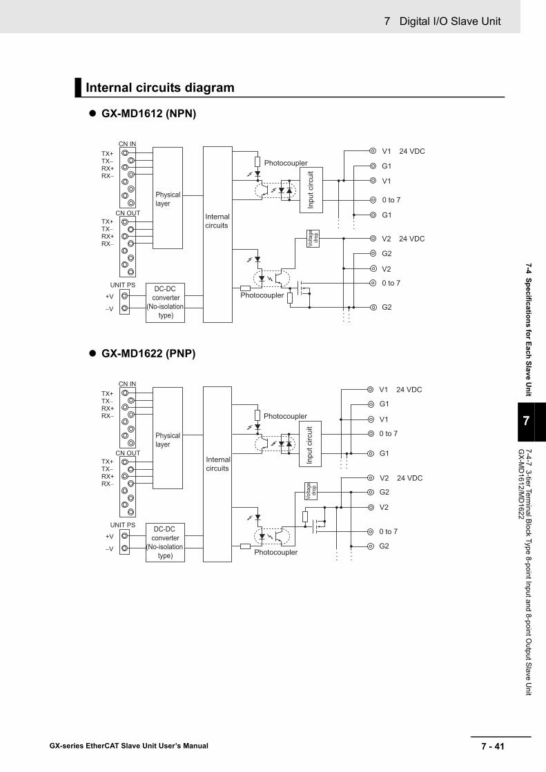
7 - 41
7 Digital I/O Slave Unit
GX-series EtherCAT Slave Unit User’s Manual
7-4 Specifications for Each Slave Unit
7
7-4-7 3-tier Terminal B
lock Type 8-point Input and 8-point Output S
lave Unit
GX
-MD
1612/MD
1622
GX-MD1612 (NPN)
GX-MD1622 (PNP)
Internal circuits diagram
V1 24 VDC
G1
V1
0 to 7
G1
V2 24 VDC
G2
V2
0 to 7
G2
Internal circuits
Photocoupler
Photocoupler
Inpu
t circ
uit
Volta
ge
drop
TX+
Physical layer
DC-DC converter
(No-isolation type)
TX−RX+RX−
TX+TX−RX+RX−
CN IN
CN OUT
UNIT PS
+V
−V
•••
•••
•••
•••
V1 24 VDC
G1
V1
0 to 7
G1
V2 24 VDC
G2
V2
0 to 7
G2
Internal circuits
Photocoupler
Photocoupler
Inpu
t circ
uit
TX+
Physical layer
DC-DC converter
(No-isolation type)
TX−RX+RX−
TX+TX−RX+RX−
CN IN
CN OUT
UNIT PS
+V
−V
Volta
ge
drop
•••
•••
•••
•••

7 Digital I/O Slave Unit
7 - 42 GX-series EtherCAT Slave Unit User’s Manual
GX-MD1612 (NPN)
GX-MD1622 (PNP)
Wiring diagram
NC NC 0 10 1 2 3 4 5 6 7
V1 V1 V1 V1 V1 V1 V1 V1
G1 G1 G1 G1 G1 G1 G1 G1
V1
G1
V2 V2 V2 V2 V2 V2 V2 V2 V2
G2 G2 G2 G2 G2 G2 G2 G2 G2
NPN output 3-wire sensor
(Photoelectric sensor, proximity sensor)
2-wire sensor(Limit switch, etc.)
Blu
e (b
lack
)
Blac
k (w
hite
)
Bro
wn
(red
)
Brow
n (w
hite
)
Blu
e (b
lack
)
Solenoid valve, etc. NPN input 3-wire external device
(Emitter of photoelectric sensor)
Blu
e (b
lack
)
Pin
k (w
hite
)
Bro
wn
(red
)I/O power supply(24 VDC)
I/O power supply
(24 VDC)
2 3 4 5 6 7
NC NC 0 10 1 2 3 4 5 6 7
V1 V1 V1 V1 V1 V1 V1 V1
G1 G1 G1 G1 G1 G1 G1 G1
V1
G1
V2 V2 V2 V2 V2 V2 V2 V2 V2
G2 G2 G2 G2 G2 G2 G2 G2 G2
PNP output 3-wire sensor
(Photoelectric sensor, proximity sensor)
2-wire sensor(Limit switch, etc.)
Blue
(bla
ck)
Blac
k (w
hite
)
Brow
n (re
d)
Brow
n (w
hite
)
Blue
(bla
ck)
Solenoid valve, etc. PNP input 3-wire external device
(Emitter of photoelectric sensor)
Blue
(bla
ck)
Pink
(whi
te)
Brow
n (re
d)I/O power supply(24 VDC)
I/O power supply
(24 VDC)
2 3 4 5 6 7
7 - 43
7 Digital I/O Slave Unit
GX-series EtherCAT Slave Unit User’s Manual
7-4 Specifications for Each Slave Unit
7
7-4-7 3-tier Terminal B
lock Type 8-point Input and 8-point Output S
lave Unit
GX
-MD
1612/MD
1622
Precautions for Correct Use
• The V1 and V2 terminals as well as the G1 and G2 terminals of the I/O power supply are not connected internally. Supply power separately for V1-G1 and V2-G2.
• Use a maximum current of 500 mA for each V1, V2, G1, and G2 terminals aside from the I/O power supply terminals.
• When using an inductive load, such as a solenoid valve, either use a built-in diode for absorbing the counterelectromotive force or install an external diode. (Refer to "A-4 Wiring External Output Signal Lines" in Page A - 71.)
• Do not wire NC terminals.
Reference
Wire colors have been changed according to revisions in the JIS standards for photoelectric and proximity sensors. The colors in parentheses are the wire colors prior to the revisions.

7 Digital I/O Slave Unit
7 - 44 GX-series EtherCAT Slave Unit User’s Manual
Notes For the I/O power supply current value to V and G terminals ,refer to "A-5 I/O Power Supply Current" in Page A - 72.
7-4-8 e-CON Connector Type 16-point Input Slave Unit GX-ID1618/ID1628
Specification
ItemSpecification
GX-ID1618 GX-ID1628Input capacity 16 pointsInternal I/O common NPN PNP
ON voltage15 VDC min. (between each input terminal and the V terminal)
15 VDC min. (between each input terminal and the G terminal)
OFF voltage5 VDC max. (between each input terminal and the V terminal)
5 VDC max. (between each input terminal and the G terminal)
OFF current 1.0 mA max.
Input current6.0 mA max./input (at 24-VDC)3.0 mA max./input (at 17-VDC)
ON delay 0.1 ms max.OFF delay 0.2 ms max.
Input filter valueWithout filter, 0.5 ms, 1 ms, 2 ms, 4 ms, 8 ms, 16 ms, 32 ms(Default setting: 1 ms)
Number of circuits per common
16 points/common
Input indicators LED display (yellow)Isolation method No isolationI/O power supply method Supplied from unit power supplyInput device supply current
100 mA/point
Unit power supply current consumption
150 mA max. (for 20.4 to 26.4-VDC power supply voltage)
e-CON connector insertion durability
50 times
Weight 140 g max.Expansion functions NoShort-circuit protection function
Available (Operates at 50 mA/point min.)

7 - 45
7 Digital I/O Slave Unit
GX-series EtherCAT Slave Unit User’s Manual
7-4 Specifications for Each Slave Unit
7
7-4-8 e-CO
N C
onnector Type 16-point Input Slave U
nit GX-ID
1618/ID1628
Terminal arrangement diagram
Names and functions
No. Name Function(1) Communications connectors
Refer to "6-3 Specifications of Common Areas" in Page 6 - 4.(2) Unit power supply connector(3) Status indicators(4) Node Address setting Switches
(5) Input indicators (0 to 15)Indicates the state of an input contact (ON/OFF).
Not lit: Contact OFF (input OFF state)Lit in yellow: Contact ON (input ON state)
(6) I/O connectors (0 to 15) Connects an external device.(7) DIN track mounting hook Fixes a Slave Unit to a DIN track.
(5)
(1)
(6)
(2)
(3) (4)
(7)
0 1 2 3 4 5 6 7
1
2
3
4
V V V V V V V V
NC NC NC NC NC NC NC NC
G0 G1 G2 G3 G4 G5 G6 G7
IN0 IN1 IN2 IN3 IN4 IN5 IN6 IN7
8 9 10 11 12 13 14 15
1
2
3
4
V V V V V V V V
NC NC NC NC NC NC NC NC
G8 G9
IN8 IN9
G10 G11 G12 G13 G14 G15
IN10 IN11 IN12 IN13 IN14 IN15
0 1 2 3 4 5 6 7
1
2
3
4
NC NC NC NC NC NC NC NC
8 9 10 11 12 13 14 15
1
2
3
4
NC NC NC NC NC NC NC NC
V0 V1 V2 V3 V4 V5 V6 V7
IN0 IN1 IN2 IN3 IN4 IN5 IN6 IN7
V8 V9
IN8 IN9
V10 V11 V12 V13 V14 V15
IN10 IN11 IN12 IN13 IN14 IN15
G G G G G G G G
G G G G G G G G
GX-ID1618 GX-ID1628

7 Digital I/O Slave Unit
7 - 46 GX-series EtherCAT Slave Unit User’s Manual
GX-ID1618 (NPN)
GX-ID1628 (PNP)
Internal circuits diagram
VNCG0IN0
VNCG1IN1
Inpu
t circ
uit
Inpu
t circ
uit
Short-circuit protection element
Short-circuit protection element
Photocoupler
Photocoupler
TX+
Physical layer
DC-DC converter
(No-isolation type)
TX−RX+RX−
TX+TX−RX+RX−
CN IN
CN OUT
UNIT PS
+V
−V
Inte
rnal
circ
uits
•••
Inpu
t circ
uit
Inpu
t circ
uit
V0NCGIN0
V1NCGIN1
Short-circuit protection element
Short-circuit protection element
Photocoupler
Photocoupler
TX+
Physical layer
DC-DCconverter
(No-isolation type)
TX−RX+RX−
TX+TX−RX+RX−
CN IN
CN OUT
UNIT PS
+V
−V
Inte
rnal
circ
uits
•••
•••

7 - 47
7 Digital I/O Slave Unit
GX-series EtherCAT Slave Unit User’s Manual
7-4 Specifications for Each Slave Unit
7
7-4-8 e-CO
N C
onnector Type 16-point Input Slave U
nit GX-ID
1618/ID1628
GX-ID1618 (NPN)
GX-ID1628 (PNP)
Reference
Wire colors have been changed according to revisions in the JIS standards for photoelectric and proximity sensors. The colors in parentheses are the wire colors prior to the revisions.
Wiring diagram
2-wire sensor(Limit switch, etc.)
Brow
n (w
hite)
Blu
e (b
lack
)
NPN output 3-wire sensor(Photoelectric sensor,
proximity sensor)
Blu
e (b
lack
)
Blac
k (w
hite
)
Bro
wn
(red
)
V V V V V V V V
NC NC NC NC NC NC NC NC
G0 G1 G2 G3 G4 G5 G6 G7
IN0 IN1 IN2 IN3 IN4 IN5 IN6 IN7
V V V V V V V V
NC NC NC NC NC NC NC NC
G8 G9
IN8 IN9
G10 G11 G12 G13 G14 G15
IN10 IN11 IN12 IN13 IN14 IN15
2-wire sensor(Limit switch, etc.)
Brow
n (w
hite
)
Blu
e (b
lack
)
PNP output 3-wire sensor(Photoelectric sensor,
proximity sensor)
Blu
e (b
lack
)
Blac
k (w
hite
)
Bro
wn
(red
)
NC NC NC NC NC NC NC NC
NC NC NC NC NC NC NC
V0 V1 V2 V3 V4 V5 V6 V7
IN0 IN1 IN2 IN3 IN4 IN5 IN6 IN7
V8 V9
IN8 IN9
V10 V11 V12 V13 V14 V15
IN10 IN11 IN12 IN13 IN14 IN15
G G G G G G G G
G G G G G G G G
NC
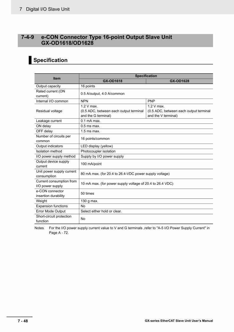
7 Digital I/O Slave Unit
7 - 48 GX-series EtherCAT Slave Unit User’s Manual
Notes For the I/O power supply current value to V and G terminals ,refer to "A-5 I/O Power Supply Current" in Page A - 72.
7-4-9 e-CON Connector Type 16-point Output Slave UnitGX-OD1618/OD1628
Specification
ItemSpecification
GX-OD1618 GX-OD1628Output capacity 16 pointsRated current (ON current)
0.5 A/output, 4.0 A/common
Internal I/O common NPN PNP
Residual voltage1.2 V max.(0.5 ADC, between each output terminal and the G terminal)
1.2 V max.(0.5 ADC, between each output terminal and the V terminal)
Leakage current 0.1 mA max.ON delay 0.5 ms max.OFF delay 1.5 ms max.Number of circuits per common
16 points/common
Output indicators LED display (yellow)Isolation method Photocoupler isolationI/O power supply method Supply by I/O power supplyOutput device supply current
100 mA/point
Unit power supply current consumption
80 mA max. (for 20.4 to 26.4-VDC power supply voltage)
Current consumption from I/O power supply
10 mA max. (for power supply voltage of 20.4 to 26.4 VDC)
e-CON connector insertion durability
50 times
Weight 130 g max.Expansion functions NoError Mode Output Select either hold or clear.Short-circuit protection function
No

7 - 49
7 Digital I/O Slave Unit
GX-series EtherCAT Slave Unit User’s Manual
7-4 Specifications for Each Slave Unit
7
7-4-9 e-CO
N C
onnector Type 16-point Output S
lave Unit G
X-O
D1618/O
D1628
Terminal arrangement diagram
Names and functions
No. Name Function(1) Communications connectors
Refer to "6-3 Specifications of Common Areas" in Page 6 - 4.(2) Unit power supply connector(3) Status indicators(4) Node Address setting Switches
(5) Output indicators (0 to 15)Indicates the state of an output contact (ON/OFF).
Not lit: Contact OFF (output OFF state)Lit in yellow: Contact ON (output ON state)
(6) I/O connectors (0 to 15) Connects an external device.(7) I/O power supply connector Supplies the I/O power.(8) DIN track mounting hook Fixes a Slave Unit to a DIN track.
(5)
(1)
(6)
(2)
(3) (4)
(7) (8)
0 1 2 3 4 5 6 7
1
2
3
4
V V V V V V V V
NC NC NC NC NC NC NC NC
8 9 10 11 12 13 14 15
1
2
3
4
V V V V V V V V
NC NC NC NC NC NC NC NC
G G G G G G G G
G G G G G G G G
OUT8
OUT9
OUT10
OUT11
OUT12
OUT13
OUT14
OUT15
OUT0
OUT1
OUT2
OUT3
OUT4
OUT5
OUT6
OUT7

7 Digital I/O Slave Unit
7 - 50 GX-series EtherCAT Slave Unit User’s Manual
GX-OD1618 (NPN)
GX-OD1628 (PNP)
Internal circuits diagram
VNCGOUT1
VNCGOUT0
V
GG
V
Photocoupler
Photocoupler
Inte
rnal
circ
uits
Volta
ge d
rop
TX+
Physical layer
DC-DC converter
(No-isolation type)
TX−RX+RX−
TX+TX−RX+RX−
CN IN
CN OUT
UNIT PS
+V
−V
Volta
ge d
rop
•••
•••
VNCGOUT1
VVGG
NCV
GOUT0
Photocoupler
Photocoupler
Volta
gedr
opVo
ltage
drop
TX+
Physical layer
DC-DCconverter
(No-isolation type)
TX−RX+RX−
TX+TX−RX+RX−
CN IN
CN OUT
UNIT PS
+V
−V
Inte
rnal
circ
uits
•••
•••

7 - 51
7 Digital I/O Slave Unit
GX-series EtherCAT Slave Unit User’s Manual
7-4 Specifications for Each Slave Unit
7
7-4-9 e-CO
N C
onnector Type 16-point Output S
lave Unit G
X-O
D1618/O
D1628
GX-OD1618 (NPN)
GX-OD1628 (PNP)
Wiring diagram
NPN input 3-wire external device(Emitter of photoelectric sensor)
Blue
(blac
k)
Pink
(whit
e)
Brow
n (re
d)Solenoid valve, etc.
V V V V V V V V
NC NC NC NC NC NC NC NC
V V V V V V V V
NC NC NC NC NC NC NC NC
G G G G G G G G
G G G G G G G G
OUT8
OUT9
OUT10
OUT11
OUT12
OUT13
OUT14
OUT15
OUT0
OUT1
OUT2
OUT3
OUT4
OUT5
OUT6
OUT7
V
V
G
G
I/O power supply(24 VDC)
PNP input 3-wire external device(Emitter of photoelectric sensor)
Blue
(blac
k)
Pink
(whit
e)
Brow
n (re
d)
Solenoid valve, etc.
V V V V V V V V
NC NC NC NC NC NC NC NC
V V V V V V V V
NC NC NC NC NC NC NC NC
G G G G G G G G
G G G G G G G G
OUT8
OUT9
OUT10
OUT11
OUT12
OUT13
OUT14
OUT15
OUT0
OUT1
OUT2
OUT3
OUT4
OUT5
OUT6
OUT7
V
V
G
G
I/O power supply(24 VDC)

7 Digital I/O Slave Unit
7 - 52 GX-series EtherCAT Slave Unit User’s Manual
Precautions for Correct Use
• The I/O power supply connectors are equipped with two sets of V and G terminals. One set of terminals is used for the I/O power supply for the unit, and the other set is used for the I/O power supply to the next unit. Use a maximum current of 4 A per terminal.
• When using an inductive load, such as a solenoid valve, either use a built-in diode for absorbing the counterelectromotive force or install an external diode. (Refer to "A-4 Wiring External Output Signal Lines" in Page A - 71.)
Reference
Wire colors have been changed according to revisions in the JIS standards for photoelectric and proximity sensors. The colors in parentheses are the wire colors prior to the revisions.

7 - 53
7 Digital I/O Slave Unit
GX-series EtherCAT Slave Unit User’s Manual
7-4 Specifications for Each Slave Unit
7
7-4-10 e-CO
N C
onnector Type 8-point Input and 8-point Output S
lave Unit
GX
-MD
1618/MD
1628
Common to input section and output section
Input section
7-4-10 e-CON Connector Type 8-point Input and 8-point Output Slave Unit GX-MD1618/MD1628
Specification
ItemSpecification
GX-MD1618 GX-MD1628Internal I/O common NPN PNPI/O indicators LED display (yellow)Unit power supply current consumption
120 mA max. (for 20.4 to 26.4-VDC power supply voltage)
e-CON connector insertion durability
50 times
Weight 140 g max.Expansion functions NoShort-circuit protection function
Available at input section only (Operates at 50 mA/point min.)
ItemSpecification
GX-MD1618 GX-MD1628Input capacity 8 points
ON voltage15 VDC min. (between each input terminal and the V terminal)
15 VDC min. (between each input terminal and the G terminal)
OFF voltage5 VDC max. (between each input terminal and the V terminal)
5 VDC max. (between each input terminal and the G terminal)
OFF current 1.0 mA max.
Input current6.0 mA max./input (at 24-VDC)3.0 mA max./input (at 17-VDC)
ON delay 0.1 ms max.OFF delay 0.2 ms max.
Input filter valueWithout filter, 0.5 ms, 1 ms, 2 ms, 4 ms, 8 ms, 16 ms, 32 ms(Default setting: 1 ms)
Number of circuits per common
8 points/common
Isolation method No-isolationI/O power supply method Supplied from unit power supplyInput device supply current
100 mA/point
I/O power supply current consumption
10 mA max. (for 20.4 to 26.4-VDC power supply voltage)
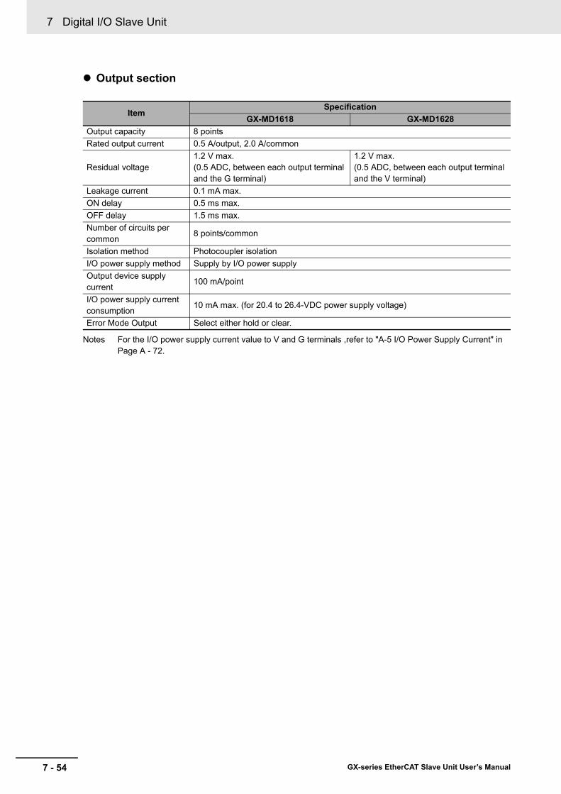
7 Digital I/O Slave Unit
7 - 54 GX-series EtherCAT Slave Unit User’s Manual
Output section
Notes For the I/O power supply current value to V and G terminals ,refer to "A-5 I/O Power Supply Current" in Page A - 72.
ItemSpecification
GX-MD1618 GX-MD1628Output capacity 8 pointsRated output current 0.5 A/output, 2.0 A/common
Residual voltage1.2 V max.(0.5 ADC, between each output terminal and the G terminal)
1.2 V max.(0.5 ADC, between each output terminal and the V terminal)
Leakage current 0.1 mA max.ON delay 0.5 ms max.OFF delay 1.5 ms max.Number of circuits per common
8 points/common
Isolation method Photocoupler isolationI/O power supply method Supply by I/O power supplyOutput device supply current
100 mA/point
I/O power supply current consumption
10 mA max. (for 20.4 to 26.4-VDC power supply voltage)
Error Mode Output Select either hold or clear.
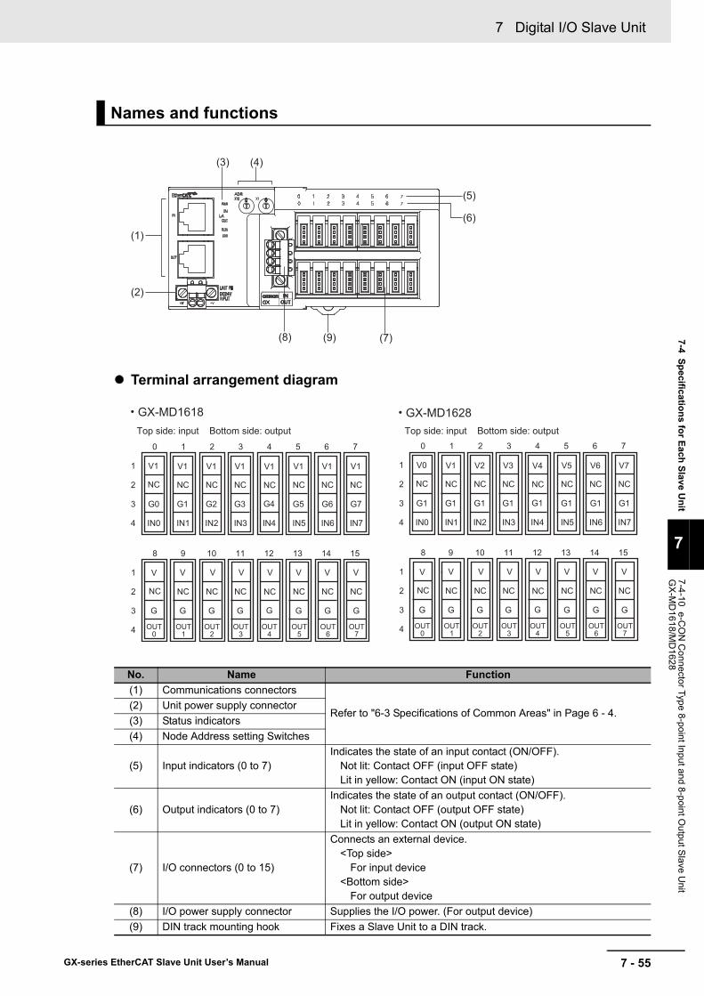
7 - 55
7 Digital I/O Slave Unit
GX-series EtherCAT Slave Unit User’s Manual
7-4 Specifications for Each Slave Unit
7
7-4-10 e-CO
N C
onnector Type 8-point Input and 8-point Output S
lave Unit
GX
-MD
1618/MD
1628
Terminal arrangement diagram
Names and functions
No. Name Function(1) Communications connectors
Refer to "6-3 Specifications of Common Areas" in Page 6 - 4.(2) Unit power supply connector(3) Status indicators(4) Node Address setting Switches
(5) Input indicators (0 to 7)Indicates the state of an input contact (ON/OFF).
Not lit: Contact OFF (input OFF state)Lit in yellow: Contact ON (input ON state)
(6) Output indicators (0 to 7)Indicates the state of an output contact (ON/OFF).
Not lit: Contact OFF (output OFF state)Lit in yellow: Contact ON (output ON state)
(7) I/O connectors (0 to 15)
Connects an external device.<Top side>
For input device<Bottom side>
For output device(8) I/O power supply connector Supplies the I/O power. (For output device)(9) DIN track mounting hook Fixes a Slave Unit to a DIN track.
(5)
(1)
(7)
(2)
(3) (4)
(9)(8)
(6)
Top side: input Bottom side: output
GX-MD1618
●
0 1 2 3 4 5 6 7
1
2
3
4
NC NC NC NC NC NC NC NC
8 9 10 11 12 13 14 15
1
2
3
4
V V V V V V V V
NC NC NC NC NC NC NC NC
G G G G G G G G
OUT0
OUT1
OUT2
OUT3
OUT4
OUT5
OUT6
OUT7
V1 V1 V1 V1 V1 V1 V1 V1
G0 G1 G2 G3 G4 G5 G6 G7
IN0 IN1 IN2 IN3 IN4 IN5 IN6 IN7
0 1 2 3 4 5 6 7
1
2
3
4
NC NC NC NC NC NC NC NC
8 9 10 11 12 13 14 15
1
2
3
4
V V V V V V V V
NC NC NC NC NC NC NC NC
G G G G G G G G
OUT0
OUT1
OUT2
OUT3
OUT4
OUT5
OUT6
OUT7
V0 V1 V2 V3 V4 V5 V6 V7
G1 G1 G1 G1 G1 G1 G1 G1
IN0 IN1 IN2 IN3 IN4 IN5 IN6 IN7
Top side: input Bottom side: output
GX-MD1628
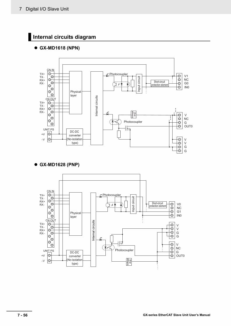
7 Digital I/O Slave Unit
7 - 56 GX-series EtherCAT Slave Unit User’s Manual
GX-MD1618 (NPN)
GX-MD1628 (PNP)
Internal circuits diagram
V1 NC G0 IN0
V NC G OUT0
V
G G
V In
put c
ircui
t
Short-circuit protection element
Photocoupler
Photocoupler
TX+
Physical layer
DC-DC converter
(No-isolation type)
TX− RX+ RX−
TX+ TX− RX+ RX−
CN IN
CN OUT
UNIT PS
+V
−V
Inte
rnal
circ
uits
• • •
•••
Volta
ge
drop
Inpu
t circ
uit
V0NCG1IN0
VVGG
NCV
GOUT0
Photocoupler
Photocoupler
TX+
Physical layer
DC-DC converter
(No-isolation type)
TX−RX+RX−
TX+TX−RX+RX−
CN IN
CN OUT
UNIT PS
+V
−V
Inte
rnal
circ
uits
Short-circuit protection element
•••
•••
•••
•••
Volta
ge
drop

7 - 57
7 Digital I/O Slave Unit
GX-series EtherCAT Slave Unit User’s Manual
7-4 Specifications for Each Slave Unit
7
7-4-10 e-CO
N C
onnector Type 8-point Input and 8-point Output S
lave Unit
GX
-MD
1618/MD
1628
GX-MD1618 (NPN)
GX-MD1628 (PNP)
Wiring diagram
2-wire sensor(Limit switch, etc.)
Brow
n (w
hite
)
Blue
(bla
ck)
NPN output 3-wire sensor
(Photoelectric sensor, proximity sensor)
Blu
e (b
lack
)
Blac
k (w
hite
)
Bro
wn
(red
)
NC NC NC NC NC NC NC NC
G0 G1 G2 G3 G4 G5 G6 G7
IN0 IN1 IN2 IN3 IN4 IN5 IN6 IN7
V V V V V V V V
NC NC NC NC NC NC NC NC
V
V
G
G
G G G G G G G G
OUT0
OUT1
OUT2
OUT3
OUT4
OUT5
OUT6
OUT7
V1 V1 V1 V1 V1 V1 V1 V1
NPN input 3-wire external device
(Emitter of photoelectric sensor)
Blu
e (b
lack
)
Pin
k (w
hite
)
Bro
wn
(red
)
Solenoid valve, etc.
I/O power supply(24 VDC)
2-wire sensor(Limit switch, etc.)
Brow
n (w
hite)
Blu
e (b
lack
)
PNP output 3-wire sensor
(Photoelectric sensor, proximity sensor)
Blu
e (b
lack
)
Blac
k (w
hite
)
Bro
wn
(red
)
NC NC NC NC NC NC NC NC
G1 G1 G1 G1 G1 G1 G1 G1
IN0 IN1 IN2 IN3 IN4 IN5 IN6 IN7
V V V V V V V V
NC NC NC NC NC NC NC NC
V
V
G
G
G G G G G G G G
OUT0
OUT1
OUT2
OUT3
OUT4
OUT5
OUT6
OUT7
V0 V1 V2 V3 V4 V5 V6 V7
PNP input 3-wire external device
(Emitter ofphotoelectric sensor)
Blu
e (b
lack
)
Pin
k (w
hite
)
Bro
wn
(red
)
Solenoid valve, etc.
I/O power supply(24 VDC)

7 Digital I/O Slave Unit
7 - 58 GX-series EtherCAT Slave Unit User’s Manual
Precautions for Correct Use
• The I/O power supply connectors are equipped with two sets of V and G terminals. One set of terminals is used for the I/O power supply for the unit, and the other set is used for the I/O power supply to the next unit. Use a maximum current of 4 A per terminal.
• When using an inductive load, such as a solenoid valve, either use a built-in diode for absorbing the counterelectromotive force or install an external diode. (Refer to "A-4 Wiring External Output Signal Lines" in Page A - 71.)
Reference
Wire colors have been changed according to revisions in the JIS standards for photoelectric and proximity sensors. The colors in parentheses are the wire colors prior to the revisions.

7 - 59
7 Digital I/O Slave Unit
GX-series EtherCAT Slave Unit User’s Manual
7-4 Specifications for Each Slave Unit
7
7-4-11 e-CO
N C
onnector Type 32-point Input Slave U
nit GX
-ID3218/ID
3228
Notes For the I/O power supply current value to V and G terminals ,refer to "A-5 I/O Power Supply Current" in Page A - 72.
7-4-11 e-CON Connector Type 32-point Input Slave Unit GX-ID3218/ID3228
Specification
ItemSpecification
GX-ID3218 GX-ID3228Input capacity 32 pointsInternal I/O common NPN PNP
ON voltage15 VDC min. (between each input terminal and the V terminal)
15 VDC min. (between each input terminal and the G terminal)
OFF voltage5 VDC max. (between each input terminal and the V terminal)
5 VDC max. (between each input terminal and the G terminal)
OFF current 1.0 mA max.
Input current6.0 mA max./input (at 24-VDC)3.0 mA max./input (at 17-VDC)
ON delay 0.1 ms max.OFF delay 0.2 ms max.
Input filter valueWithout filter, 0.5 ms, 1 ms, 2 ms, 4 ms, 8 ms, 16 ms, 32 ms(Default setting: 1 ms)
Number of circuits per common
32 points/common
Input indicators LED display (yellow)Isolation method No isolationI/O power supply method Supplied from unit power supplyInput device supply current
100 mA/point
Unit power supply current consumption
230 mA max. (for 20.4 to 26.4-VDC power supply voltage)
e-CON connector insertion durability
50 times
Weight 220 g max.Expansion functions NoShort-circuit protection function
Available (Operates at 50 mA/point min.)

7 Digital I/O Slave Unit
7 - 60 GX-series EtherCAT Slave Unit User’s Manual
Terminal arrangement diagram• GX-ID3218
• GX-ID3228
Names and functions
(5)
(1)
(6)
(2)
(3) (4)
(7)
0 1 2 3 4 5 6 7
1
2
3
4
V V V V V V V V
NC NC NC NC NC NC NC NC
G0 G1 G2 G3 G4 G5 G6 G7
IN0 IN1 IN2 IN3 IN4 IN5 IN6 IN7
8 9 10 11 12 13 14 15
1
2
3
4
V V V V V V V V
NC NC NC NC NC NC NC NC
G8 G9
IN8 IN9
G10 G11 G12 G13 G14 G15
IN10 IN11 IN12 IN13 IN14 IN15
0 1 2 3 4 5 6 7
1
2
3
4
V V V V V V V V
NC NC NC NC NC NC NC NC
G0 G1 G2 G3 G4 G5 G6 G7
IN0 IN1 IN2 IN3 IN4 IN5 IN6 IN7
8 9 10 11 12 13 14 15
1
2
3
4
V V V V V V V V
NC NC NC NC NC NC NC NC
G8 G9
IN8 IN9
G10 G11 G12 G13 G14 G15
IN10 IN11 IN12 IN13 IN14 IN15
IN1 IN2
0 1 2 3 4 5 6 7
1
2
3
4
NC NC NC NC NC NC NC NC
8 9 10 11 12 13 14 15
1
2
3
4
NC NC NC NC NC NC NC NC
V0 V1 V2 V3 V4 V5 V6 V7
IN0 IN1 IN2 IN3 IN4 IN5 IN6 IN7
V8 V9
IN8 IN9
V10 V11 V12 V13 V14 V15
IN10 IN11 IN12 IN13 IN14 IN15
G G G G G G G G
G G G G G G G G
0 1 2 3 4 5 6 7
1
2
3
4
NC NC NC NC NC NC NC NC
8 9 10 11 12 13 14 15
1
2
3
4
NC NC NC NC NC NC NC NC
V0 V1 V2 V3 V4 V5 V6 V7
IN0 IN1 IN2 IN3 IN4 IN5 IN6 IN7
V8 V9
IN8 IN9
V10 V11 V12 V13 V14 V15
IN10 IN11 IN12 IN13 IN14 IN15
G G G G G G G G
G G G G G G G G
IN1 IN2

7 - 61
7 Digital I/O Slave Unit
GX-series EtherCAT Slave Unit User’s Manual
7-4 Specifications for Each Slave Unit
7
7-4-11 e-CO
N C
onnector Type 32-point Input Slave U
nit GX
-ID3218/ID
3228
No. Name Function(1) Communications connectors
Refer to "6-3 Specifications of Common Areas" in Page 6 - 4.(2) Unit power supply connector(3) Status indicators(4) Node Address setting Switches
(5)Input indicators(IN1 0 to 15, IN2 0 to 15)
Indicates the state of an input contact (ON/OFF).Not lit: Contact OFF (input OFF state)Lit in yellow: Contact ON (input ON state)
(6) I/O connectors (0 to 15 × 2) Connects an external device.(7) DIN track mounting hook Fixes a Slave Unit to a DIN track.

7 Digital I/O Slave Unit
7 - 62 GX-series EtherCAT Slave Unit User’s Manual
GX-ID3218 (NPN)
GX-ID3228 (PNP)
Internal circuits diagram
VNCG0IN0
VNCG1IN1
Inpu
t circ
uit
Inpu
t circ
uit
Short-circuit protection element
Short-circuit protection element
Photocoupler
Photocoupler
TX+
Physical layer
DC-DC converter
(No-isolation type)
TX−RX+RX−
TX+TX−RX+RX−
CN IN
CN OUT
UNIT PS
+V
−V
Inte
rnal
circ
uits
•••
Inpu
t circ
uit
V0NCGIN0
V1NCGIN1
Photocoupler
Photocoupler
TX+
Physical layer
DC-DC converter
(No-isolation type)
TX−RX+RX−
TX+TX−RX+RX−
CN IN
CN OUT
UNIT PS
+V
−V
Inte
rnal
circ
uits
Inpu
t circ
uit
Short-circuit protection element
Short-circuit protection element
•••
•••

7 - 63
7 Digital I/O Slave Unit
GX-series EtherCAT Slave Unit User’s Manual
7-4 Specifications for Each Slave Unit
7
7-4-11 e-CO
N C
onnector Type 32-point Input Slave U
nit GX
-ID3218/ID
3228
GX-ID3218 (NPN)
GX-ID3228 (PNP)
Reference
Wire colors have been changed according to revisions in the JIS standards for photoelectric and proximity sensors. The colors in parentheses are the wire colors prior to the revisions.
Wiring diagram
2-wire sensor(Limit switch, etc.)
Brow
n (wh
ite)
Blue
(blac
k)
NPN output 3-wire sensor(Photoelectric sensor, proximity sensor)
Blue
(blac
k)
Blac
k (wh
ite)
Brow
n (re
d)
V V V V V V V V
NC NC NC NC NC NC NC NC
G0 G1 G2 G3 G4 G5 G6 G7
IN0 IN1 IN2 IN3 IN4 IN5 IN6 IN7
V V V V V V V V
NC NC NC NC NC NC NC NC
G8 G9
IN8 IN9
G10 G11 G12 G13 G14 G15
IN10 IN11 IN12 IN13 IN14 IN15
V V V V V V V V
NC NC NC NC NC NC NC NC
G0 G1 G2 G3 G4 G5 G6 G7
IN0 IN1 IN2 IN3 IN4 IN5 IN6 IN7
V V V V V V V V
NC NC NC NC NC NC NC NC
G8 G9
IN8 IN9
G10 G11 G12 G13 G14 G15
IN10 IN11 IN12 IN13 IN14 IN15
2-wire sensor(Limit switch, etc.)
Brow
n (wh
ite)
Blue
(blac
k)
PNP output 3-wire sensor(Photoelectric sensor, proximity sensor)
Blue
(blac
k)
Blac
k (wh
ite)
Brow
n (re
d)
NC NC NC NC NC NC NC NC
NC NC NC NC NC NC NC
V0 V1 V2 V3 V4 V5 V6 V7
IN0 IN1 IN2 IN3 IN4 IN5 IN6 IN7
V8 V9
IN8 IN9
V10 V11 V12 V13 V14 V15
IN10 IN11 IN12 IN13 IN14 IN15
G G G G G G G G
G G G G G G G G
NC
NC NC NC NC NC NC NC NC
NC NC NC NC NC NC NC
V0 V1 V2 V3 V4 V5 V6 V7
IN0 IN1 IN2 IN3 IN4 IN5 IN6 IN7
V8 V9
IN8 IN9
V10 V11 V12 V13 V14 V15
IN10 IN11 IN12 IN13 IN14 IN15
G G G G G G G G
G G G G G G G G
NC

7 Digital I/O Slave Unit
7 - 64 GX-series EtherCAT Slave Unit User’s Manual
Notes For the I/O power supply current value to V and G terminals ,refer to "A-5 I/O Power Supply Current" in Page A - 72.
7-4-12 e-CON Connector Type 32-point Output Slave UnitGX-OD3218/OD3228
Specification
ItemSpecification
GX-OD3218 GX-OD3228Output capacity 32 pointsRated current (ON current)
0.5 A/output, 4.0 A/common
Internal I/O common NPN PNP
Residual voltage1.2 V max.(0.5 ADC, between each output terminal and the G terminal)
1.2 V max.(0.5 ADC, between each output terminal and the V terminal)
Leakage current 0.1 mA max.ON delay 0.5 ms max.OFF delay 1.5 ms max.Number of circuits per common
16 points/common
Output indicators LED display (yellow)Isolation method Photocoupler isolationI/O power supply method Supply by I/O power supplyOutput device supply current
100 mA/point
Unit power supply current consumption
100 mA max. (for 20.4 to 26.4-VDC power supply voltage)
Current consumption from I/O power supply
10 mA max. (for power supply voltage of 20.4 to 26.4 VDC)
e-CON connector insertion durability
50 times
Weight 210 g max.Expansion functions NoError Mode Output Select either hold or clear.Short-circuit protection function
No

7 - 65
7 Digital I/O Slave Unit
GX-series EtherCAT Slave Unit User’s Manual
7-4 Specifications for Each Slave Unit
7
7-4-12 e-CO
N C
onnector Type 32-point Output S
lave Unit G
X-O
D3218/O
D3228
Terminal arrangement diagram
Names and functions
No. Name Function(1) Communications connectors
Refer to "6-3 Specifications of Common Areas" in Page 6 - 4.(2) Unit power supply connector(3) Status indicators(4) Node Address setting Switches
(5)Output indicators(OUT1 0 to 15, OUT2 0 to 15)
Indicates the state of an output contact (ON/OFF).Not lit: Contact OFF (output OFF state)Lit in yellow: Contact ON (output ON state)
(6) I/O connectors (0 to 15 × 2) Connects an external device.(7) I/O power supply connectors ( × 2) Supplies the I/O power.(8) DIN track mounting hook Fixes a Slave Unit to a DIN track.
(5)
(1)
(6)
(2)
(3) (4)
(7) (8)
0 1 2 3 4 5 6 7
1
2
3
4
V V V V V V V V
NC NC NC NC NC NC NC NC
8 9 10 11 12 13 14 15
1
2
3
4
V V V V V V V V
NC NC NC NC NC NC NC NC
G G G G G G G G
G G G G G G G G
OUT8
OUT9
OUT10
OUT11
OUT12
OUT13
OUT14
OUT15
OUT0
OUT1
OUT2
OUT3
OUT4
OUT5
OUT6
OUT7
0 1 2 3 4 5 6 7
1
2
3
4
V V V V V V V V
NC NC NC NC NC NC NC NC
8 9 10 11 12 13 14 15
1
2
3
4
V V V V V V V V
NC NC NC NC NC NC NC NC
G G G G G G G G
G G G G G G G G
OUT8
OUT9
OUT10
OUT11
OUT12
OUT13
OUT14
OUT15
OUT0
OUT1
OUT2
OUT3
OUT4
OUT5
OUT6
OUT7
OUT1 OUT2

7 Digital I/O Slave Unit
7 - 66 GX-series EtherCAT Slave Unit User’s Manual
GX-OD3218 (NPN)
GX-OD3228 (PNP)
Internal circuits diagram
VNCGOUT0
V
GG
V
Left side
VNCGOUT0
V
GG
V
Right side
Photocoupler
Photocoupler
Inte
rnal
circ
uits
TX+
Physical layer
DC-DC converter
(No-isolation type)
TX−RX+RX−
TX+TX−RX+RX−
CN IN
CN OUT
UNIT PS
+V
−V
Volta
ge
drop
Volta
ge
drop
•••
•••
•••
•••
VVGG
NCV
GOUT0
VVGG
NCV
GOUT0
Left side
Right side
Photocoupler
Photocoupler
TX+
Physical layer
DC-DC converter
(No-isolation type)
TX−RX+RX−
TX+TX−RX+RX−
CN IN
CN OUT
UNIT PS
+V
−V
Inte
rnal
circ
uits
Volta
ge
drop
Volta
ge
drop
•••
•••
•••
•••

7 - 67
7 Digital I/O Slave Unit
GX-series EtherCAT Slave Unit User’s Manual
7-4 Specifications for Each Slave Unit
7
7-4-12 e-CO
N C
onnector Type 32-point Output S
lave Unit G
X-O
D3218/O
D3228
GX-OD3218 (NPN)
GX-OD3228 (PNP)
Wiring diagram
V V V V V V V V
NC NC NC NC NC NC NC NC
V V V V V V V V
NC NC NC NC NC NC NC NC
V V V V V V V V
NC NC NC NC NC NC NC NC
V V V V V V V V
NC NC NC NC NC NC NC NC
NPN input 3-wire external device(Emitter of photoelectric sensor)
Blue
(blac
k)
Pink
(whit
e)
Brow
n (re
d)Solenoid valve, etc.
V
V
G
G
V
V
G
G
OUT0
OUT1
OUT2
OUT3
OUT4
OUT5
OUT6
OUT7
OUT8
OUT9
OUT10
OUT11
OUT12
OUT13
OUT14
OUT15
G G G G G G G G
G G G G G G G G
OUT8
OUT9
OUT10
OUT11
OUT12
OUT13
OUT14
OUT15
G G G G G G G G
OUT0
OUT1
OUT2
OUT3
OUT4
OUT5
OUT6
OUT7
G G G G G G G G
I/O power supply(24 VDC)
V V V V V V V V
NC NC NC NC NC NC NC NC
V V V V V V V V
NC NC NC NC NC NC NC NC
V V V V V V V V
NC NC NC NC NC NC NC NC
V V V V V V V V
NC NC NC NC NC NC NC NC
PNP input 3-wire external device(Emitter of photoelectric sensor)
Blue
(blac
k)
Pink
(whit
e)
Brow
n (re
d)
Solenoid valve, etc.
V
V
G
G
V
V
G
G
OUT0
OUT1
OUT2
OUT3
OUT4
OUT5
OUT6
OUT7
OUT8
OUT9
OUT10
OUT11
OUT12
OUT13
OUT14
OUT15
G G G G G G G G
G G G G G G G G
OUT8
OUT9
OUT10
OUT11
OUT12
OUT13
OUT14
OUT15
G G G G G G G G
OUT0
OUT1
OUT2
OUT3
OUT4
OUT5
OUT6
OUT7
G G G G G G G G
I/O power supply(24 VDC)

7 Digital I/O Slave Unit
7 - 68 GX-series EtherCAT Slave Unit User’s Manual
Precautions for Correct Use
• The I/O power supply connectors on the left and right are equipped with two sets of V and G terminals. One set of terminals is used for the I/O power supply for the unit, and the other set is used for the I/O power supply to the next unit. Use a maximum current of 4 A per terminal.
• When using an inductive load, such as a solenoid valve, either use a built-in diode for absorbing the counterelectromotive force or install an external diode. (Refer to "A-4 Wiring External Output Signal Lines" in Page A - 71.)
Reference
Wire colors have been changed according to revisions in the JIS standards for photoelectric and proximity sensors. The colors in parentheses are the wire colors prior to the revisions.
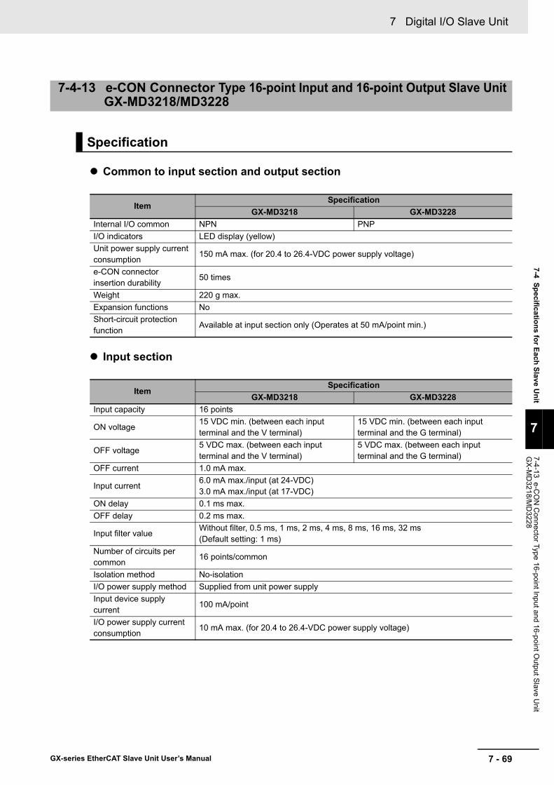
7 - 69
7 Digital I/O Slave Unit
GX-series EtherCAT Slave Unit User’s Manual
7-4 Specifications for Each Slave Unit
7
7-4-13 e-CO
N C
onnector Type 16-point Input and 16-point Output Slave U
nit G
X-M
D3218/M
D3228
Common to input section and output section
Input section
7-4-13 e-CON Connector Type 16-point Input and 16-point Output Slave Unit GX-MD3218/MD3228
Specification
ItemSpecification
GX-MD3218 GX-MD3228Internal I/O common NPN PNPI/O indicators LED display (yellow)Unit power supply current consumption
150 mA max. (for 20.4 to 26.4-VDC power supply voltage)
e-CON connector insertion durability
50 times
Weight 220 g max.Expansion functions NoShort-circuit protection function
Available at input section only (Operates at 50 mA/point min.)
ItemSpecification
GX-MD3218 GX-MD3228Input capacity 16 points
ON voltage15 VDC min. (between each input terminal and the V terminal)
15 VDC min. (between each input terminal and the G terminal)
OFF voltage5 VDC max. (between each input terminal and the V terminal)
5 VDC max. (between each input terminal and the G terminal)
OFF current 1.0 mA max.
Input current6.0 mA max./input (at 24-VDC)3.0 mA max./input (at 17-VDC)
ON delay 0.1 ms max.OFF delay 0.2 ms max.
Input filter valueWithout filter, 0.5 ms, 1 ms, 2 ms, 4 ms, 8 ms, 16 ms, 32 ms(Default setting: 1 ms)
Number of circuits per common
16 points/common
Isolation method No-isolationI/O power supply method Supplied from unit power supplyInput device supply current
100 mA/point
I/O power supply current consumption
10 mA max. (for 20.4 to 26.4-VDC power supply voltage)

7 Digital I/O Slave Unit
7 - 70 GX-series EtherCAT Slave Unit User’s Manual
Output section
Notes For the I/O power supply current value to V and G terminals ,refer to "A-5 I/O Power Supply Current" in Page A - 72.
ItemSpecification
GX-MD3218 GX-MD3228Output capacity 16 pointsRated output current 0.5 A/output, 2.0 A/common
Residual voltage1.2 V max.(0.5 ADC, between each output terminal and the G terminal)
1.2 V max.(0.5 ADC, between each output terminal and the V terminal)
Leakage current 0.1 mA max.ON delay 0.5 ms max.OFF delay 1.5 ms max.Number of circuits per common
16 points/common
Isolation method Photocoupler isolationI/O power supply method Supply by I/O power supplyOutput device supply current
100 mA/point
I/O power supply current consumption
10 mA max. (for 20.4 to 26.4-VDC power supply voltage)
Error Mode Output Select either hold or clear.

7 - 71
7 Digital I/O Slave Unit
GX-series EtherCAT Slave Unit User’s Manual
7-4 Specifications for Each Slave Unit
7
7-4-13 e-CO
N C
onnector Type 16-point Input and 16-point Output Slave U
nit G
X-M
D3218/M
D3228
Terminal arrangement diagram
Names and functions
No. Name Function(1) Communications connectors
Refer to "6-3 Specifications of Common Areas" in Page 6 - 4.(2) Unit power supply connector(3) Status indicators(4) Node Address setting Switches
(5) Input indicators (0 to 15)Indicates the state of an input contact (ON/OFF).
Not lit: Contact OFF (input OFF state)Lit in yellow: Contact ON (input ON state)
(6) Output indicators (0 to 15)Indicates the state of an output contact (ON/OFF).
Not lit: Contact OFF (output OFF state)Lit in yellow: Contact ON (output ON state)
(7) I/O connectors (1 to 16 × 2)
Connects an external device.<Left side>
For input device<Right side>
For output device(8) I/O power supply connector Supplies the I/O power. (For output device)(9) DIN track mounting hook Fixes a Slave Unit to a DIN track.
(5)
(1)
(7)
(2)
(3) (4)
(9) (8)
(6)
0 1 2 3 4 5 6 7
1
2
3
4
NC NC NC NC NC NC NC NC
0 1 2 3 4 5 6 7
1
2
3
4
V V V V V V V V
NC NC NC NC NC NC NC NC
G G G G G G G G
OUT0
OUT1
OUT2
OUT3
OUT4
OUT5
OUT6
OUT7
G0 G1 G2 G3 G4 G5 G6 G7
IN0 IN1 IN2 IN3 IN4 IN5 IN6 IN7
V V V V V V V V
8 9 10 11 12 13 14 15
1
2
3
4
V V V V V V V V
NC NC NC NC NC NC NC NC
G G G G G G G G
OUT8
OUT9
OUT10
OUT11
OUT12
OUT13
OUT14
OUT15
8 9 10 11 12 13 14 15
1
2
3
4
V V V V V V V V
NC NC NC NC NC NC NC NC
G8 G9
IN8 IN9
G10 G11 G12 G13 G14 G15
IN10 IN11 IN12 IN13 IN14 IN15
Left side (input) Right side (output)
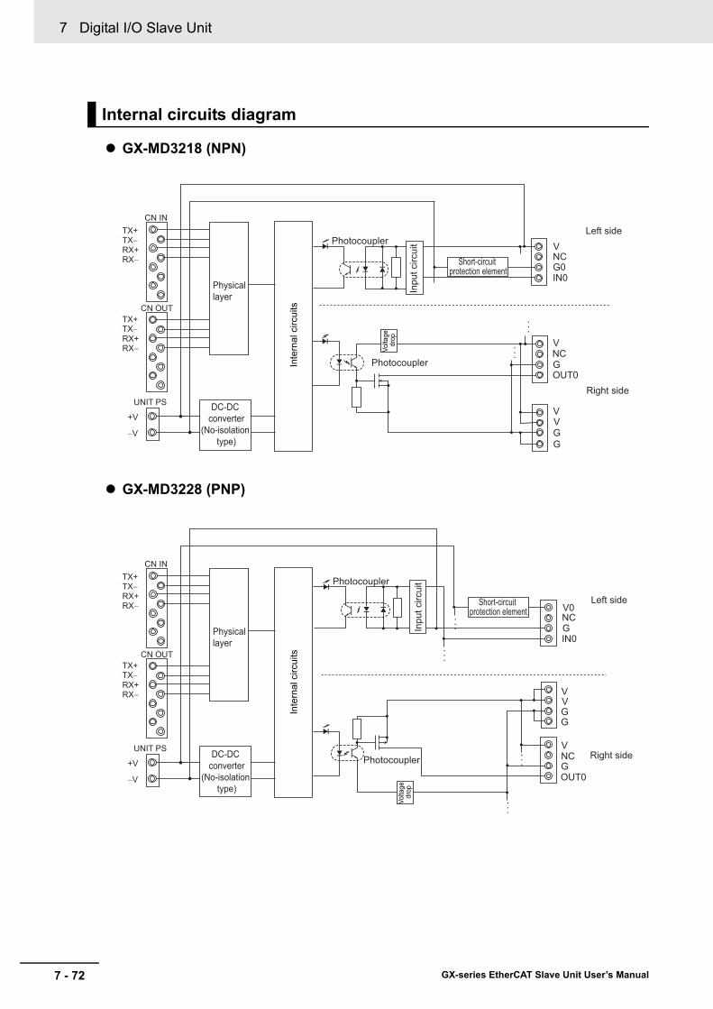
7 Digital I/O Slave Unit
7 - 72 GX-series EtherCAT Slave Unit User’s Manual
GX-MD3218 (NPN)
GX-MD3228 (PNP)
Internal circuits diagram
VNCG0IN0
VNCGOUT0
V
GG
VIn
put c
ircui
t
Left side
Right side
Photocoupler
Photocoupler
TX+
Physical layer
DC-DC converter
(No-isolation type)
TX−RX+RX−
TX+TX−RX+RX−
CN IN
CN OUT
UNIT PS
+V
−V
Inte
rnal
circ
uits
Short-circuit protection element
Volta
ge
drop
•••
•••
Inpu
t circ
uit
V0NCGIN0
VVGG
NCV
GOUT0
Left side
Right side
Photocoupler
Photocoupler
Short-circuit protection element
TX+
Physical layer
DC-DC converter
(No-isolation type)
TX−RX+RX−
TX+TX−RX+RX−
CN IN
CN OUT
UNIT PS
+V
−V
Inte
rnal
circ
uits •
••
•••
•••
•••
Volta
ge
drop
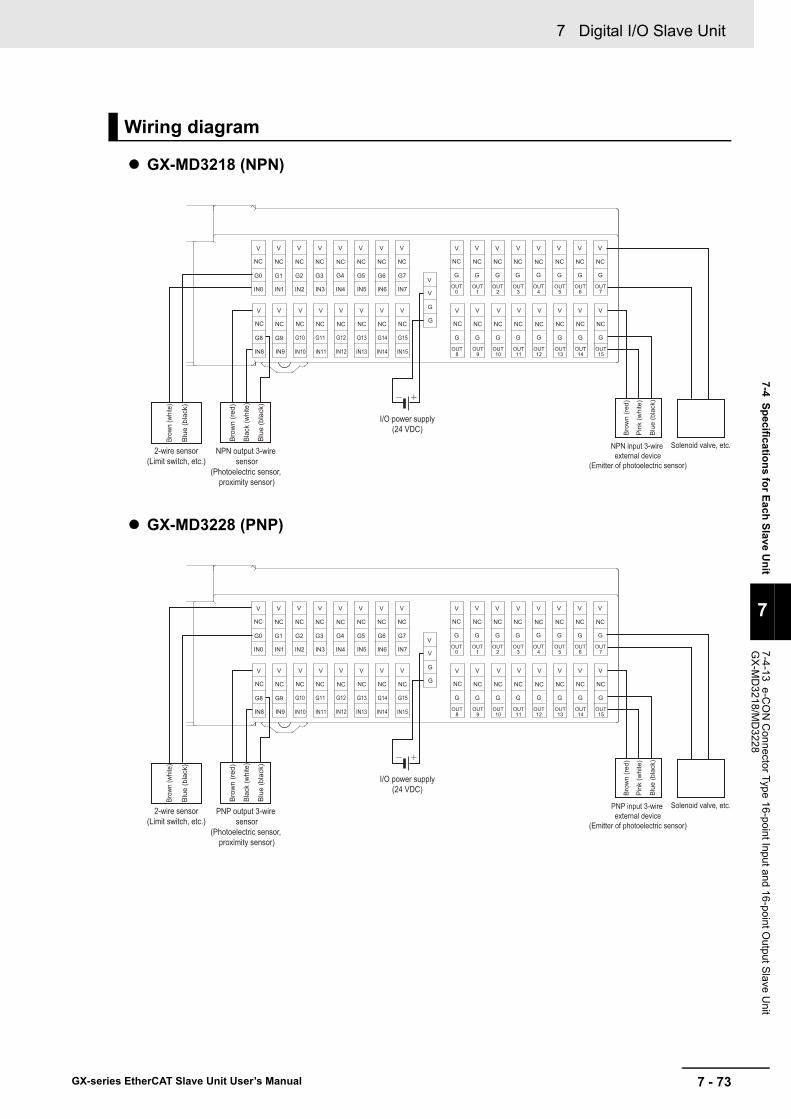
7 - 73
7 Digital I/O Slave Unit
GX-series EtherCAT Slave Unit User’s Manual
7-4 Specifications for Each Slave Unit
7
7-4-13 e-CO
N C
onnector Type 16-point Input and 16-point Output Slave U
nit G
X-M
D3218/M
D3228
GX-MD3218 (NPN)
GX-MD3228 (PNP)
Wiring diagram
V V V V V V V V
NC NC NC NC NC NC NC NC
V V V V V V V V
NC NC NC NC NC NC NC NC
V V V V V V V V
NC NC NC NC NC NC NC NC
V V V V V V V V
NC NC NC NC NC NC NC NC
V
V
G
G
OUT8
OUT9
OUT10
OUT11
OUT12
OUT13
OUT14
OUT15
G G G G G G G G
OUT0
OUT1
OUT2
OUT3
OUT4
OUT5
OUT6
OUT7
G G G G G G G GG0 G1 G2 G3 G4 G5 G6 G7
IN0 IN1 IN2 IN3 IN4 IN5 IN6 IN7
G8 G9
IN8 IN9
G10 G11 G12 G13 G14 G15
IN10 IN11 IN12 IN13 IN14 IN15
2-wire sensor(Limit switch, etc.)
Brow
n (w
hite
)
Blu
e (b
lack
)
NPN output 3-wire sensor
(Photoelectric sensor, proximity sensor)
Blu
e (b
lack
)
Blac
k (w
hite
)
Bro
wn
(red
)
NPN input 3-wire external device
(Emitter of photoelectric sensor)
Blu
e (b
lack
)
Pin
k (w
hite
)
Bro
wn
(red
)
Solenoid valve, etc.
I/O power supply(24 VDC)
V V V V V V V V
NC NC NC NC NC NC NC NC
V V V V V V V V
NC NC NC NC NC NC NC NC
V V V V V V V V
NC NC NC NC NC NC NC NC
V V V V V V V V
NC NC NC NC NC NC NC NC
V
V
G
G
OUT8
OUT9
OUT10
OUT11
OUT12
OUT13
OUT14
OUT15
G G G G G G G G
OUT0
OUT1
OUT2
OUT3
OUT4
OUT5
OUT6
OUT7
G G G G G G G GG0 G1 G2 G3 G4 G5 G6 G7
IN0 IN1 IN2 IN3 IN4 IN5 IN6 IN7
G8 G9
IN8 IN9
G10 G11 G12 G13 G14 G15
IN10 IN11 IN12 IN13 IN14 IN15
2-wire sensor(Limit switch, etc.)
Brow
n (w
hite
)
Blu
e (b
lack
)
PNP output 3-wire sensor
(Photoelectric sensor, proximity sensor)
Blu
e (b
lack
)
Blac
k (w
hite
)
Bro
wn
(red
)
PNP input 3-wire external device
(Emitter of photoelectric sensor)
Blu
e (b
lack
)
Pin
k (w
hite
)
Bro
wn
(red
)
Solenoid valve, etc.
I/O power supply(24 VDC)

7 Digital I/O Slave Unit
7 - 74 GX-series EtherCAT Slave Unit User’s Manual
Precautions for Correct Use
• The I/O power supply connectors are equipped with two sets of V and G terminals. One set of terminals is used for the I/O power supply for the unit, and the other set is used for the I/O power supply to the next unit. Use a maximum current of 4 A per terminal.
• When using an inductive load, such as a solenoid valve, either use a built-in diode for absorbing the counterelectromotive force or install an external diode. (Refer to "A-4 Wiring External Output Signal Lines" in Page A - 71.)
Reference
Wire colors have been changed according to revisions in the JIS standards for photoelectric and proximity sensors. The colors in parentheses are the wire colors prior to the revisions.

7 - 75
7 Digital I/O Slave Unit
GX-series EtherCAT Slave Unit User’s Manual
7-5 Mounting D
imensions
7
7-5-1 2-tier Terminal B
lock Type
7-5 Mounting Dimensions
The mounting dimensions of a Digital I/O Slave Unit are shown below.
GX-ID1611/ID1621/OD1611/OD1621
GX-OC1601
7-5-1 2-tier Terminal Block Type
73.9
57.1
50
135
52
3.14
(mm)
74.4
57.6
50
160
52
3.14
(mm)

7 Digital I/O Slave Unit
7 - 76 GX-series EtherCAT Slave Unit User’s Manual
GX-MD1611/MD1621
7-5-2 3-tier Terminal Block Type
73.9
57.1
50
13552
3.14
(mm)
10.1
93.5
200
52 503.
14
68.9
(mm)

7 - 77
7 Digital I/O Slave Unit
GX-series EtherCAT Slave Unit User’s Manual
7-5 Mounting D
imensions
7
7-5-3 e-CO
N C
onnector Type
GX-ID1618/ID1628
GX-OD1618/OD1628/MD1618/MD1628
7-5-3 e-CON Connector Type
5052
115
3.14
43.8
5
(mm)
5052
115
3.14
49.8
(mm)

7 Digital I/O Slave Unit
7 - 78 GX-series EtherCAT Slave Unit User’s Manual
GX-ID3218/ID3228
GX-OD3218/OD3228
3.14
52180
50
43.8
5
(mm)
3.14
52
180
50
49.8
(mm)

7 - 79
7 Digital I/O Slave Unit
GX-series EtherCAT Slave Unit User’s Manual
7-5 Mounting D
imensions
7
7-5-3 e-CO
N C
onnector Type
GX-MD3218/MD3228
3.14
52180
50
49.8
(mm)

7 Digital I/O Slave Unit
7 - 80 GX-series EtherCAT Slave Unit User’s Manual

8 - 1
8
GX-series EtherCAT Slave Unit User’s Manual
This chapter explains the overview of the Analog I/O Slave Unit.
8-1 Analog I/O Slave Unit . . . . . . . . . . . . . . . . . . . . . . . . . . . . . . . . . . . . . . . . . . . 8-28-2 Overview of the Analog Input Slave Unit . . . . . . . . . . . . . . . . . . . . . . . . . . . 8-3
8-2-1 Input Range and Converted Data . . . . . . . . . . . . . . . . . . . . . . . . . . . . . . . . . . . 8-38-2-2 I/O Data Allocation (PDO Mapping) . . . . . . . . . . . . . . . . . . . . . . . . . . . . . . . . . 8-6
8-3 Function of the Analog Input Slave Unit . . . . . . . . . . . . . . . . . . . . . . . . . . . 8-78-3-1 AD Conversion Available Point Setting . . . . . . . . . . . . . . . . . . . . . . . . . . . . . . . 8-78-3-2 Moving Average . . . . . . . . . . . . . . . . . . . . . . . . . . . . . . . . . . . . . . . . . . . . . . . . 8-88-3-3 Disconnected Line Detection . . . . . . . . . . . . . . . . . . . . . . . . . . . . . . . . . . . . . 8-108-3-4 User adjustment . . . . . . . . . . . . . . . . . . . . . . . . . . . . . . . . . . . . . . . . . . . . . . . 8-10
8-4 Overview of the Analog Output Slave Unit . . . . . . . . . . . . . . . . . . . . . . . . 8-128-4-1 Output Range and Converted Data . . . . . . . . . . . . . . . . . . . . . . . . . . . . . . . . 8-128-4-2 I/O Data Allocation (PDO Mapping) . . . . . . . . . . . . . . . . . . . . . . . . . . . . . . . . 8-14
8-5 Function of the Analog Output Slave Unit . . . . . . . . . . . . . . . . . . . . . . . . . 8-158-5-1 DA Conversion Available Point Setting . . . . . . . . . . . . . . . . . . . . . . . . . . . . . . 8-158-5-2 Analog Output Fault Action . . . . . . . . . . . . . . . . . . . . . . . . . . . . . . . . . . . . . . . 8-168-5-3 User Adjustment . . . . . . . . . . . . . . . . . . . . . . . . . . . . . . . . . . . . . . . . . . . . . . . 8-17
8-6 Overview of Each Slave Unit Type . . . . . . . . . . . . . . . . . . . . . . . . . . . . . . . 8-188-6-1 4-point Input Slave Unit GX-AD0471 . . . . . . . . . . . . . . . . . . . . . . . . . . . . . . . 8-198-6-2 2-point Output Slave Unit GX-DA0271 . . . . . . . . . . . . . . . . . . . . . . . . . . . . . . 8-23
8-7 Mounting Dimensions . . . . . . . . . . . . . . . . . . . . . . . . . . . . . . . . . . . . . . . . . 8-27
Analog I/O Slave Unit

8 Analog I/O Slave Unit
8 - 2 GX-series EtherCAT Slave Unit User’s Manual
8-1 Analog I/O Slave Unit
Analog I/O Slave Units refer to slaves with processing functions for analog I/O data (voltage value/current value).Other functions of the Slave Unit include the Moving Average and User Adjustment.
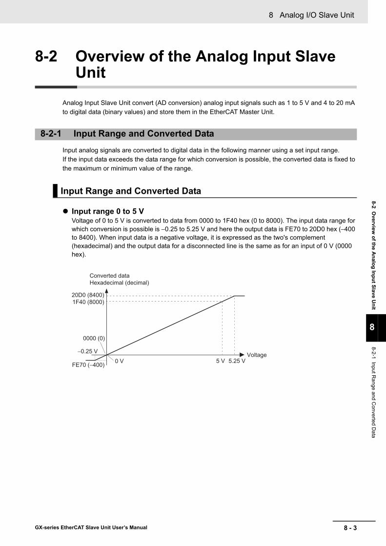
8 - 3
8 Analog I/O Slave Unit
GX-series EtherCAT Slave Unit User’s Manual
8-2 Overview
of the Analog Input Slave U
nit
8
8-2-1 Input Range and C
onverted Data
8-2 Overview of the Analog Input Slave Unit
Analog Input Slave Unit convert (AD conversion) analog input signals such as 1 to 5 V and 4 to 20 mA to digital data (binary values) and store them in the EtherCAT Master Unit.
Input analog signals are converted to digital data in the following manner using a set input range.If the input data exceeds the data range for which conversion is possible, the converted data is fixed to the maximum or minimum value of the range.
Input range 0 to 5 VVoltage of 0 to 5 V is converted to data from 0000 to 1F40 hex (0 to 8000). The input data range for which conversion is possible is −0.25 to 5.25 V and here the output data is FE70 to 20D0 hex (−400 to 8400). When input data is a negative voltage, it is expressed as the two's complement (hexadecimal) and the output data for a disconnected line is the same as for an input of 0 V (0000 hex).
8-2-1 Input Range and Converted Data
Input Range and Converted Data
0 V
−0.25 V5 V 5.25 V
20D0 (8400)1F40 (8000)
FE70 (−400)
0000 (0)
Converted dataHexadecimal (decimal)
Voltage

8 Analog I/O Slave Unit
8 - 4 GX-series EtherCAT Slave Unit User’s Manual
Input range 1 to 5 VVoltage of 1 to 5 V is converted to data from 0000 to 1F40 hex (0 to 8000). The input data range for which conversion is possible is 0.8 to 5.2 V and here the output data is FE70 to 20D0 hex (−400 to +8400). If the input voltage drops below the input range to lower than 0.3 V due to disconnection and so on, the disconnected line detection is activated and the data is set to 7FFF hex.
Input range 0 to 10 VVoltage of 0 to 10 V is converted to data from 0000 to 1F40 hex (0 to 8000). The input data range for which conversion is possible is −0.5 to 10.5 V and here the output data is FE70 to 20D0 hex (−400 to +8400). When input data is a negative voltage, it is expressed as the two's complement (hexadecimal) and the output data for a disconnected line is the same as for an input of 0 V (0000 hex).
20D0 (8400)1F40 (8000)
FE70 (−400) 1 V0.8 V 5 V
7FFF
(Disconnection in case it is less than 0.3 V)
0000 (0)5.2 V
Converted dataHexadecimal (decimal)
Voltage
0.3 V
Clamp at 5.2 V or higher
0 V
−0.5 V10 V 10.5 V
20D0 (8400)1F40 (8000)
FE70 (−400)
0000 (0)
Converted dataHexadecimal (decimal)
Voltage

8 - 5
8 Analog I/O Slave Unit
GX-series EtherCAT Slave Unit User’s Manual
8-2 Overview
of the Analog Input Slave U
nit
8
8-2-1 Input Range and C
onverted Data
Input range −10 to +10 VVoltage of −10 to +10 V is converted to data from F060 to 0F40 hex (−4000 to +4000). The input data range for which conversion is possible is −11 to +11 V and here the output data is EED0 to 1130 hex (−4400 to +4400). When input data is a negative voltage, it is expressed as the two's complement (hexadecimal) and the output data for a disconnected line is the same as for an input of 0 V (0000 hex).
Input range 4 to 20mACurrent of 4 to 20 mA is converted to data from 0000 to 1F40 hex (0 to 8000). The input data range for which conversion is possible is 3.2 to 20.8 mA and here the output data is FE70 to 20D0 hex (−400 to +8400). If the input current drops below the input range to lower than 1.2 mA due to disconnection and so on, the disconnected line detection is activated and the data is set to 7FFF hex.
The input range is set using the input range switch (DIP switch) of a Slave Unit or by SDO communications.When SDO communication is used for the setting, the target index is 3101 hex.For the set value, refer to the corresponding index of "Appendix A-1 Object Dictionary" in Page A - 40.
For how to set with the input range switch, refer to "Names and functions" in Page 8 - 20.
Input range settings
0 V−11V −10V
11 V10 V
Converted dataHexadecimal (decimal)
Voltage
1130 (4400)0FA0 (4000)
F060 (−4000)EED0 (−4400)
0000 (0)
4 mA3.2 mA 20 mA
7FFF
20D0 (8400)1F40 (8000)
FE70 (−400)0000 (0)
20.8 mA
Converted dataHexadecimal (decimal)
Current
1.2 mA(Disconnection in case it is less than 1.2 mA)
Clamp at 20.8 mA or higher
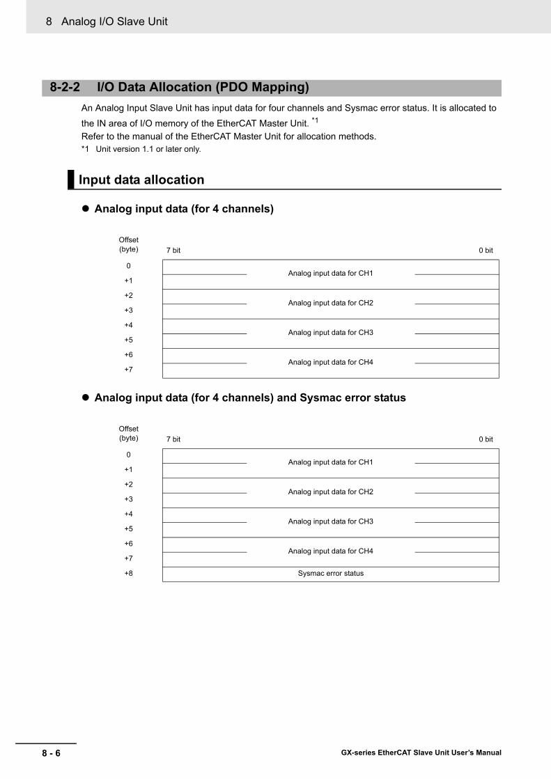
8 Analog I/O Slave Unit
8 - 6 GX-series EtherCAT Slave Unit User’s Manual
An Analog Input Slave Unit has input data for four channels and Sysmac error status. It is allocated to
the IN area of I/O memory of the EtherCAT Master Unit. *1
Refer to the manual of the EtherCAT Master Unit for allocation methods.*1 Unit version 1.1 or later only.
Analog input data (for 4 channels)
Analog input data (for 4 channels) and Sysmac error status
8-2-2 I/O Data Allocation (PDO Mapping)
Input data allocation
Offset (byte) 7 bit 0 bit
0Analog input data for CH1
+1
+2Analog input data for CH2
+3
+4Analog input data for CH3
+5
+6Analog input data for CH4
+7
Offset (byte) 7 bit 0 bit
0Analog input data for CH1
+1
+2Analog input data for CH2
+3
+4Analog input data for CH3
+5
+6Analog input data for CH4
+7
+8 Sysmac error status
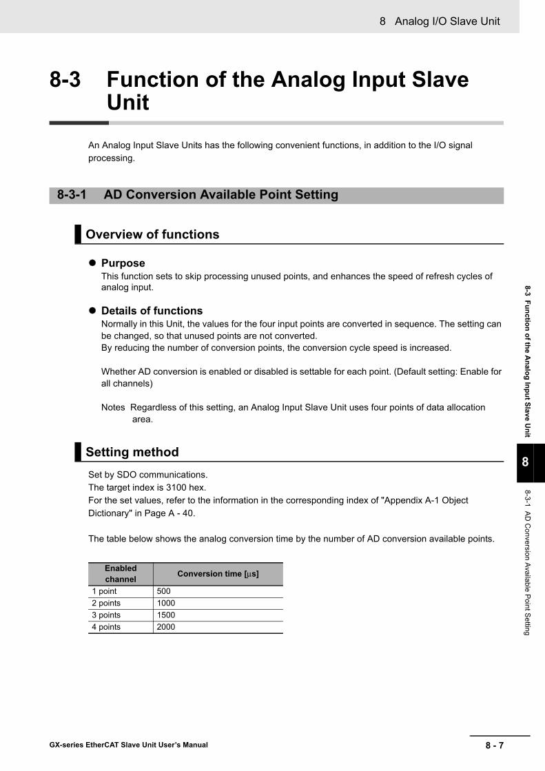
8 - 7
8 Analog I/O Slave Unit
GX-series EtherCAT Slave Unit User’s Manual
8-3 Function of the Analog Input Slave U
nit
8
8-3-1 AD
Conversion Available P
oint Setting
8-3 Function of the Analog Input Slave Unit
An Analog Input Slave Units has the following convenient functions, in addition to the I/O signal processing.
PurposeThis function sets to skip processing unused points, and enhances the speed of refresh cycles of analog input.
Details of functionsNormally in this Unit, the values for the four input points are converted in sequence. The setting can be changed, so that unused points are not converted.By reducing the number of conversion points, the conversion cycle speed is increased.
Whether AD conversion is enabled or disabled is settable for each point. (Default setting: Enable for all channels)
Notes Regardless of this setting, an Analog Input Slave Unit uses four points of data allocation area.
Set by SDO communications.The target index is 3100 hex.For the set values, refer to the information in the corresponding index of "Appendix A-1 Object Dictionary" in Page A - 40.
The table below shows the analog conversion time by the number of AD conversion available points.
8-3-1 AD Conversion Available Point Setting
Overview of functions
Setting method
Enabled channel Conversion time [μs]
1 point 5002 points 10003 points 15004 points 2000
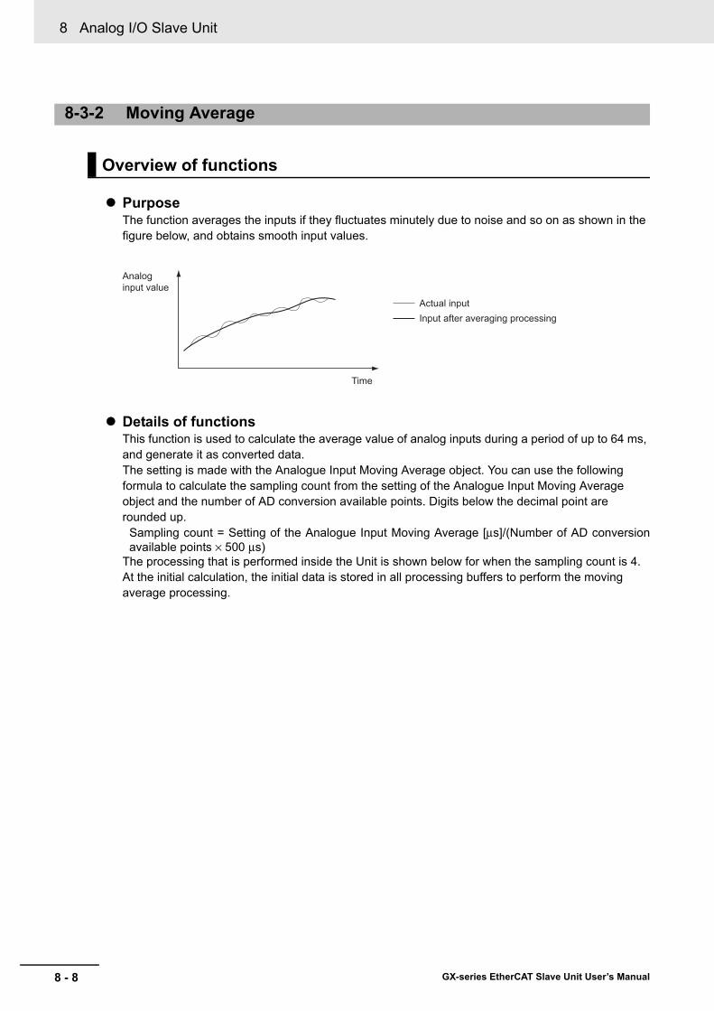
8 Analog I/O Slave Unit
8 - 8 GX-series EtherCAT Slave Unit User’s Manual
PurposeThe function averages the inputs if they fluctuates minutely due to noise and so on as shown in the figure below, and obtains smooth input values.
Details of functionsThis function is used to calculate the average value of analog inputs during a period of up to 64 ms, and generate it as converted data.The setting is made with the Analogue Input Moving Average object. You can use the following formula to calculate the sampling count from the setting of the Analogue Input Moving Average object and the number of AD conversion available points. Digits below the decimal point are rounded up.
Sampling count = Setting of the Analogue Input Moving Average [μs]/(Number of AD conversionavailable points × 500 μs)
The processing that is performed inside the Unit is shown below for when the sampling count is 4.At the initial calculation, the initial data is stored in all processing buffers to perform the moving average processing.
8-3-2 Moving Average
Overview of functions
Actual inputInput after averaging processing
Time
Analog input value

8 - 9
8 Analog I/O Slave Unit
GX-series EtherCAT Slave Unit User’s Manual
8-3 Function of the Analog Input Slave U
nit
8
8-3-2 Moving Average
Set by SDO communication.The target index is 3132 hex.For the details, refer to the information in the corresponding index of "Appendix A-1 Object Dictionary" in Page A - 42.
Setting method
Moving average calculation (Initial)
Moving average calculation (2nd)
Moving average calculation (3rd)
Moving average calculation (4th)
Moving average calculation (5th)
Moving average value = (D1 × 4) /4
Moving average value = ((D1 × 3) + D2) /4
Moving average value = ((D1 × 2) + D2 + D3) /4
Moving average value = (D1 + D2 + D3 + D4) /4
Moving average value = (D2 + D3 + D4 + D5) /4
Actual analog conversion data
Analog conversion time(number of AD conversion available points × 500 μs)
Time [ms]
D1
D2D3
D4
D5
Internal buffer
Initial data
Initial data
Initial data
Initial data
Initial data
2nd time data
Initial data
Initial data
Initial data
2nd time data
3rd time data
Initial data
Initial data
2nd time data
3rd time data
4th time data
5th time data
2nd time data
3rd time data
4th time data

8 Analog I/O Slave Unit
8 - 10 GX-series EtherCAT Slave Unit User’s Manual
PurposeThe function detects a disconnection of analog input signal line.Note that this function is valid only when the input range is "1 to 5 V" or "4 to 20 mA."
Details of functionsIf any analog input signal line (voltage/current inputs) of the points that are enabled by the "AD Conversion Available Point Setting" is disconnected, the disconnected line detection flag of that point (target index: 3136 hex) is turned ON.If the moving average is enabled, the function works to detect a disconnected line in moving average processing results.The AD converted data at disconnected line detection is 7FFF hex.
If the input returns to the convertible range again, this function is automatically cancelled and normal conversion data is input.
The table below shows details of the disconnected line detection flag.
PurposeIf final input voltage and current deviates due to characteristics of input devices and methods of connection, correct the "deviation" and adjust inputs.
Details of functionsThis function corrects conversion values of input voltages and currents at 2 points, 0% and 100%, as shown in the figure below.
8-3-3 Disconnected Line Detection
Overview of functions
Bits State0 1: CH1 disconnected / 0: CH1 normal1 1: CH2 disconnected / 0: CH2 normal2 1: CH3 disconnected / 0: CH3 normal3 1: CH4 disconnected / 0: CH4 normal4 to 15 Reserved
8-3-4 User adjustment
Overview of functions

8 - 11
8 Analog I/O Slave Unit
GX-series EtherCAT Slave Unit User’s Manual
8-3 Function of the Analog Input Slave U
nit
8
8-3-4 User adjustm
ent
The correctable range is from −5% to +5% each of the minimum and maximum input values.The correctable range for each input range is as follows.
Set by SDO communication.The target indexes are as follows.
• Upper limit correction: 3112 hex Analogue Input Adjustment High Execute (user adjustment execution (upper limit))
• Lower limit correction: 3115 hex Analogue Input Adjustment Low Execute (user adjustment execution (lower limit))
For the correction procedure, refer to the information in the corresponding index of "Appendix A-1 Object Dictionary" in Page A - 41.
Input range Low limit High limit0 to 5 V −0.25 to +0.25 V 4.75 to 5.25 V1 to 5 V 0.8 to 1.2 V 4.8 to 5.2 V0 to 10 V −0.5 to +0.5 V 9.5 to 10.5 V−10 to +10 V −11 to −9.0 V 9.0 to 11 V4 to 20 mA 3.2 to 4.8 mA 19.2 to 20.8 mA
Setting method
Converted data
Voltage/current
Before correction
After correction
0%100%
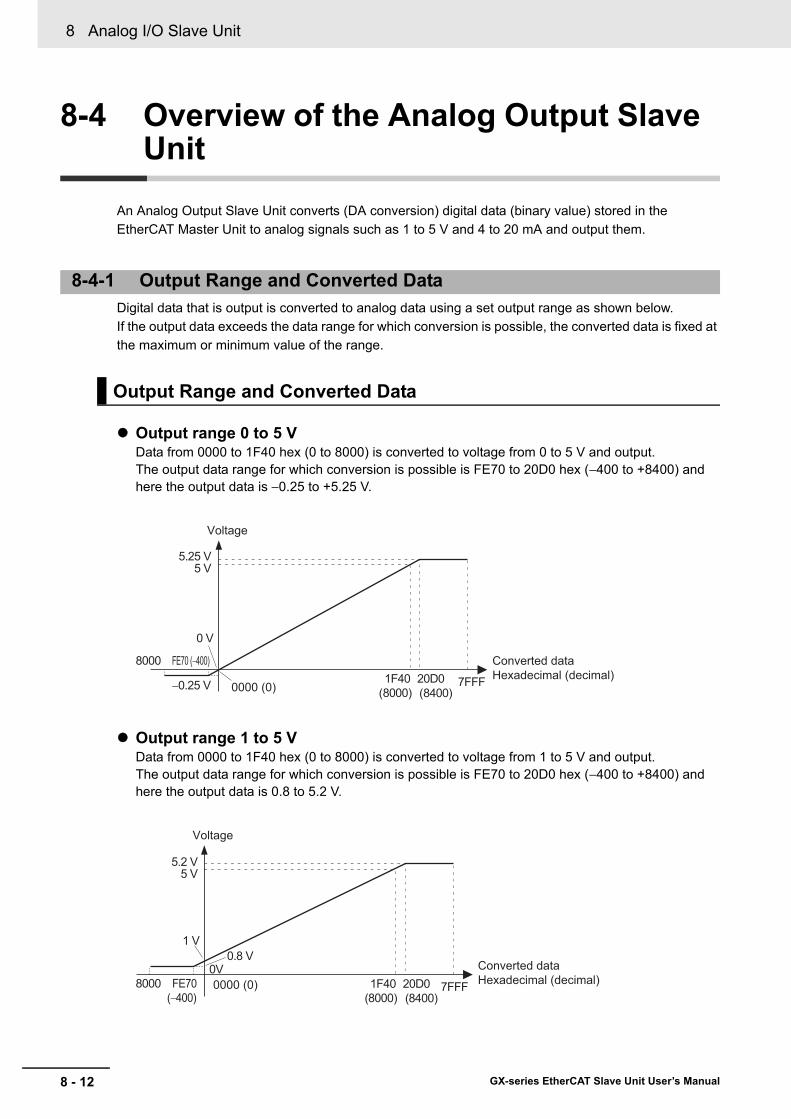
8 Analog I/O Slave Unit
8 - 12 GX-series EtherCAT Slave Unit User’s Manual
8-4 Overview of the Analog Output Slave Unit
An Analog Output Slave Unit converts (DA conversion) digital data (binary value) stored in the EtherCAT Master Unit to analog signals such as 1 to 5 V and 4 to 20 mA and output them.
Digital data that is output is converted to analog data using a set output range as shown below.If the output data exceeds the data range for which conversion is possible, the converted data is fixed at the maximum or minimum value of the range.
Output range 0 to 5 VData from 0000 to 1F40 hex (0 to 8000) is converted to voltage from 0 to 5 V and output.The output data range for which conversion is possible is FE70 to 20D0 hex (−400 to +8400) and here the output data is −0.25 to +5.25 V.
Output range 1 to 5 VData from 0000 to 1F40 hex (0 to 8000) is converted to voltage from 1 to 5 V and output.The output data range for which conversion is possible is FE70 to 20D0 hex (−400 to +8400) and here the output data is 0.8 to 5.2 V.
8-4-1 Output Range and Converted Data
Output Range and Converted Data
FE70 (−400)
0 V
−0.25 V
5.25 V5 V
8000
7FFF0000 (0)20D01F40
(8000) (8400)
Converted dataHexadecimal (decimal)
Voltage
FE70
1 V
0V0.8 V
5.2 V5 V
8000 7FFF(−400)
Converted dataHexadecimal (decimal)
Voltage
0000 (0) 20D01F40(8000) (8400)

8 - 13
8 Analog I/O Slave Unit
GX-series EtherCAT Slave Unit User’s Manual
8-4 Overview
of the Analog O
utput Slave Unit
8
8-4-1 Output R
ange and Converted D
ata
Output range 0 to 10 VData from 0000 to 1F40 hex (0 to 8000) is converted to voltage from 0 to 10 V and output.The output data range for which conversion is possible is FE70 to 20D0 hex (−400 to +8400) and here the output data is −0.5 to +10.5 V.
Output range −10 to +10 VData from F060 to 0FA0 hex (−4000 to +4000) is converted to voltage from −10 to +10 V and output.The output data range for which conversion is possible is EED0 to 1130 hex (−4400 to +4400) and here the output data is −11 to +11 V.Negative voltages are specified as two's complements (hexadecimal).
Output range 4 to 20 mAData from 0000 to 1F40 hex (0 to 8000) is converted to voltage from 4 to 20 mA and output.The output data range for which conversion is possible is FE70 to 20D0 hex (−400 to +8400) and here the output data is 3.2 to 20.8 mA.
FE70(−400)
0 V
−0.5 V
10.5 V10 V
8000
7FFF0000 (0)
Converted dataHexadecimal (decimal)
Voltage
20D01F40(8000) (8400)
0 V
11 V10 V
-10 V-11 V
8000
7FFF
0000 (0) Converted dataHexadecimal (decimal)
Voltage
11300FA0(4000) (4400)
F060EED0 (−4400) (−4000)
4 mA
0 mA3.2mA
20.8 mA20 mA
8000 7FFF0000 (0)Converted dataHexadecimal (decimal)
Current
20D01F40(8000) (8400)
FE70(−400)
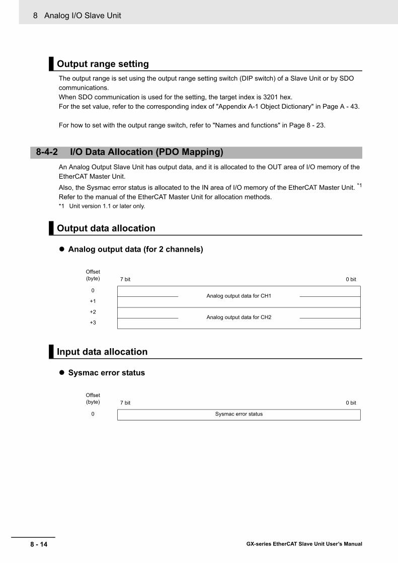
8 Analog I/O Slave Unit
8 - 14 GX-series EtherCAT Slave Unit User’s Manual
The output range is set using the output range setting switch (DIP switch) of a Slave Unit or by SDO communications.When SDO communication is used for the setting, the target index is 3201 hex.For the set value, refer to the corresponding index of "Appendix A-1 Object Dictionary" in Page A - 43.
For how to set with the output range switch, refer to "Names and functions" in Page 8 - 23.
An Analog Output Slave Unit has output data, and it is allocated to the OUT area of I/O memory of the EtherCAT Master Unit.
Also, the Sysmac error status is allocated to the IN area of I/O memory of the EtherCAT Master Unit. *1
Refer to the manual of the EtherCAT Master Unit for allocation methods.*1 Unit version 1.1 or later only.
Analog output data (for 2 channels)
Sysmac error status
Output range setting
8-4-2 I/O Data Allocation (PDO Mapping)
Output data allocation
Offset (byte) 7 bit 0 bit
0Analog output data for CH1
+1
+2Analog output data for CH2
+3
Input data allocation
Offset (byte) 7 bit 0 bit
0 Sysmac error status
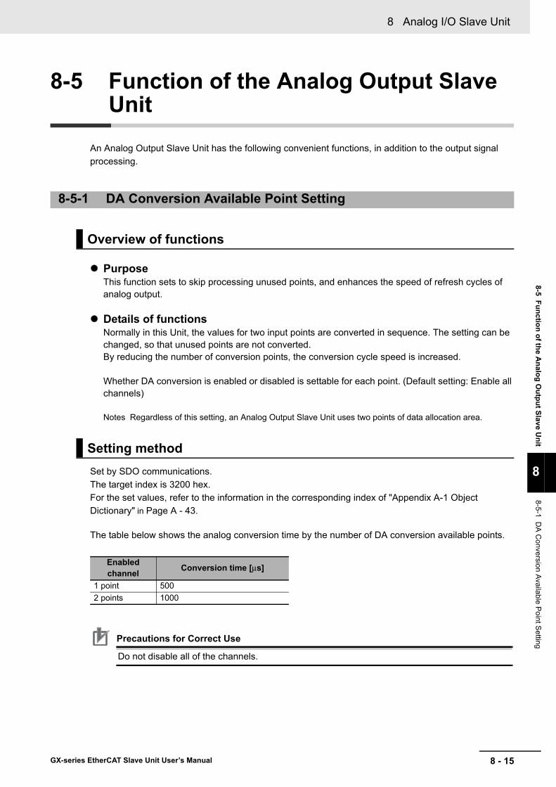
8 - 15
8 Analog I/O Slave Unit
GX-series EtherCAT Slave Unit User’s Manual
8-5 Function of the Analog O
utput Slave Unit
8
8-5-1 DA
Conversion Available P
oint Setting
8-5 Function of the Analog Output Slave Unit
An Analog Output Slave Unit has the following convenient functions, in addition to the output signal processing.
PurposeThis function sets to skip processing unused points, and enhances the speed of refresh cycles of analog output.
Details of functionsNormally in this Unit, the values for two input points are converted in sequence. The setting can be changed, so that unused points are not converted.By reducing the number of conversion points, the conversion cycle speed is increased.
Whether DA conversion is enabled or disabled is settable for each point. (Default setting: Enable all channels)
Notes Regardless of this setting, an Analog Output Slave Unit uses two points of data allocation area.
Set by SDO communications.The target index is 3200 hex.For the set values, refer to the information in the corresponding index of "Appendix A-1 Object Dictionary" in Page A - 43.
The table below shows the analog conversion time by the number of DA conversion available points.
Precautions for Correct Use
Do not disable all of the channels.
8-5-1 DA Conversion Available Point Setting
Overview of functions
Setting method
Enabled channel Conversion time [μs]
1 point 5002 points 1000

8 Analog I/O Slave Unit
8 - 16 GX-series EtherCAT Slave Unit User’s Manual
PurposeThis function outputs set values if a communications error occurs.
Details of functionsIt is possible to set a value to be output when a communications error occurs for each point.Select an output value from the following 5 patterns.
• Output value corresponding to the output range and output pattern
Set by SDO communications.The target index is 3240 hex.For the set values, refer to the information in the corresponding index of "Appendix A-1 Object Dictionary" in Page A - 45.
8-5-2 Analog Output Fault Action
Overview of functions
Output pattern ContentsHold Last State Holds and outputs the value immediately before the error occurred.
Low LimitOutputs the values in the following table according to the output range.
High LimitOutputs the values in the following table according to the output range.
User Count Outputs the value specified by users.Zero Count(Default setting) Outputs the 0000 hex values of each output range.
Output range Hold Last State
Low Limit
High Limit User Count Zero
Count
0 to 5 V
Hold
−0.25 V 5.25 VSpecified value by a user from −0.25 to 5.25 V
0 V
1 to 5 V 0.8 V 5.2 VSpecified value by a user from 0.8 to 5.2 V
1 V
0 to 10 V −0.5 V 10.5 VSpecified value by a user from −0.5 to 10.5 V
0 V
−10 to +10 V −11 V 11 VSpecified value by a user from −11 to 11 V
0 V
4 to 20 mA 3.2 mA 20.8 mASpecified value by a user from 3.2 to 20.8 mA
4 mA
Setting method
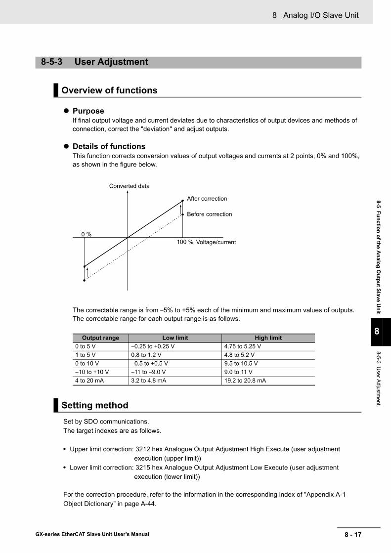
8 - 17
8 Analog I/O Slave Unit
GX-series EtherCAT Slave Unit User’s Manual
8-5 Function of the Analog O
utput Slave Unit
8
8-5-3 User A
djustment
PurposeIf final output voltage and current deviates due to characteristics of output devices and methods of connection, correct the "deviation" and adjust outputs.
Details of functionsThis function corrects conversion values of output voltages and currents at 2 points, 0% and 100%, as shown in the figure below.
The correctable range is from −5% to +5% each of the minimum and maximum values of outputs.The correctable range for each output range is as follows.
Set by SDO communications.The target indexes are as follows.
• Upper limit correction: 3212 hex Analogue Output Adjustment High Execute (user adjustment execution (upper limit))
• Lower limit correction: 3215 hex Analogue Output Adjustment Low Execute (user adjustment execution (lower limit))
For the correction procedure, refer to the information in the corresponding index of "Appendix A-1 Object Dictionary" in page A-44.
8-5-3 User Adjustment
Overview of functions
Output range Low limit High limit0 to 5 V −0.25 to +0.25 V 4.75 to 5.25 V1 to 5 V 0.8 to 1.2 V 4.8 to 5.2 V0 to 10 V −0.5 to +0.5 V 9.5 to 10.5 V−10 to +10 V −11 to −9.0 V 9.0 to 11 V4 to 20 mA 3.2 to 4.8 mA 19.2 to 20.8 mA
Setting method
Converted data
Voltage/current
Before correction
After correction
0 %100 %

8 Analog I/O Slave Unit
8 - 18 GX-series EtherCAT Slave Unit User’s Manual
8-6 Overview of Each Slave Unit Type
This section shows the specification of Analog I/O Slave Units, names and functions of each part, internal circuit diagram, and wiring diagram.Refer to the following corresponding page to each model.
Type Model
Reference page
Specification Names and functions
Internal circuits diagram
Wiring diagram
4-point Input Slave Unit
GX-AD0471 8-19 8-20 8-22 8-22
2-point Output Slave Unit
GX-DA0271 8-23 8-23 8-25 8-26

8 - 19
8 Analog I/O Slave Unit
GX-series EtherCAT Slave Unit User’s Manual
8-6 Overview
of Each Slave Unit Type
8
8-6-1 4-point Input Slave U
nit GX
-AD
0471
* Short-circuit metal fixtures are used for current input only, but store in a safe place when using for voltage inputs as well.
8-6-1 4-point Input Slave UnitGX-AD0471
Specification
ItemSpecification
Voltage input Current inputInput capacity 4 points (possible to set number of enabled points)
Input range
0 to 5 V1 to 5 V0 to 10 V−10 to +10 V
4 to 20 mA
Input range setting method
Input range switch: Common to input CH1/CH2, common to input CH3/CH4SDO communications: Possible to set input CH1 to CH4 separately
Maximum signal input ±15 V ±30 mAInput impedance 1 MΩ min. Approx. 250 ΩResolution 1/8000 (full scale)Overall accuracy
25°C ±0.3% FS ±0.4% FS−10 to 55°C ±0.6% FS ±0.8% FS
Analog conversion cycle500 μs/inputWhen 4 points are used: 2 ms max.
AD converted dataOther than ±10 V: 0000 to 1F40 hex full scale (0 to 8000)±10 V: F060 to 0FA0 Hex full scale (−4000 to +4000)AD conversion range: ±5% FS of the above data ranges.
Isolation methodPhotocoupler isolation (between input and communications lines)No isolation between input signal wires
Unit power supply current consumption
120 mA max. (for 20.4 to 26.4-VDC power supply voltage)
Weight 180 g max.Accessories Four short-circuit metal fixtures (for current input) *

8 Analog I/O Slave Unit
8 - 20 GX-series EtherCAT Slave Unit User’s Manual
Terminal arrangement diagram
Names and functions
No. Name Function(1) Communications connectors
Refer to "Specifications of Common Areas" in Page 6 - 4.(2) Unit power supply connector(3) Status indicators(4) Node Address setting Switches(5) Input range setting Switches DIP switches for setting input range (Refer to the following section.)
(6) Terminal block
Terminal block for analog input signalsV1 to V4: Voltage input terminalsI1 to I4: Current input terminalsAG: Analog GNDNC: Not used
(7) DIN track mounting hook Fixes a Slave Unit to a DIN track.
(1)
(6)
(2)
(3) (4)
(7)
(5)
V1+
I1+
V2+
I2+
V3+
I3+
V4+
I4+ NC
AG V1−
AG V2−
AG V3−
AG V4−
NC
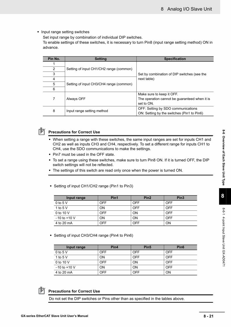
8 - 21
8 Analog I/O Slave Unit
GX-series EtherCAT Slave Unit User’s Manual
8-6 Overview
of Each Slave Unit Type
8
8-6-1 4-point Input Slave U
nit GX
-AD
0471
• Input range setting switchesSet input range by combination of individual DIP switches.To enable settings of these switches, it is necessary to turn Pin8 (input range setting method) ON in advance.
Precautions for Correct Use
• When setting a range with these switches, the same input ranges are set for inputs CH1 and CH2 as well as inputs CH3 and CH4, respectively. To set a different range for inputs CH1 to CH4, use the SDO communications to make the settings.
• Pin7 must be used in the OFF state.• To set a range using these switches, make sure to turn Pin8 ON. If it is turned OFF, the DIP
switch settings will not be reflected.• The settings of this switch are read only once when the power is turned ON.
• Setting of input CH1/CH2 range (Pin1 to Pin3)
• Setting of input CH3/CH4 range (Pin4 to Pin6)
Precautions for Correct Use
Do not set the DIP switches or Pins other than as specified in the tables above.
Pin No. Setting Specification1
Setting of input CH1/CH2 range (common)Set by combination of DIP switches (see the next table)
234
Setting of input CH3/CH4 range (common)56
7 Always OFFMake sure to keep it OFF.The operation cannot be guaranteed when it is set to ON.
8 Input range setting methodOFF: Setting by SDO communicationsON: Setting by the switches (Pin1 to Pin6)
Input range Pin1 Pin2 Pin30 to 5 V OFF OFF OFF1 to 5 V ON OFF OFF0 to 10 V OFF ON OFF−10 to +10 V ON ON OFF4 to 20 mA OFF OFF ON
Input range Pin4 Pin5 Pin60 to 5 V OFF OFF OFF1 to 5 V ON OFF OFF0 to 10 V OFF ON OFF−10 to +10 V ON ON OFF4 to 20 mA OFF OFF ON

8 Analog I/O Slave Unit
8 - 22 GX-series EtherCAT Slave Unit User’s Manual
Precautions for Correct Use
Do not wire NC terminals.
Internal circuits diagram
Wiring diagram
V+
I+
AG
V−
Analog GND
250 Ω
510 kΩ
510 kΩ
0 V
0 V
Short-circuit *
Voltage input
Current input
Short-circuit the “V positive” terminal and “I positive” terminal at current input.Use the attached short-circuit metal fixture to short-circuit these terminals.
*
V1+ I1+ V2+ I2+ V3+ I3+ V4+ I4+ NC
AG V1− AG V2− AG V3− AG V4− NC
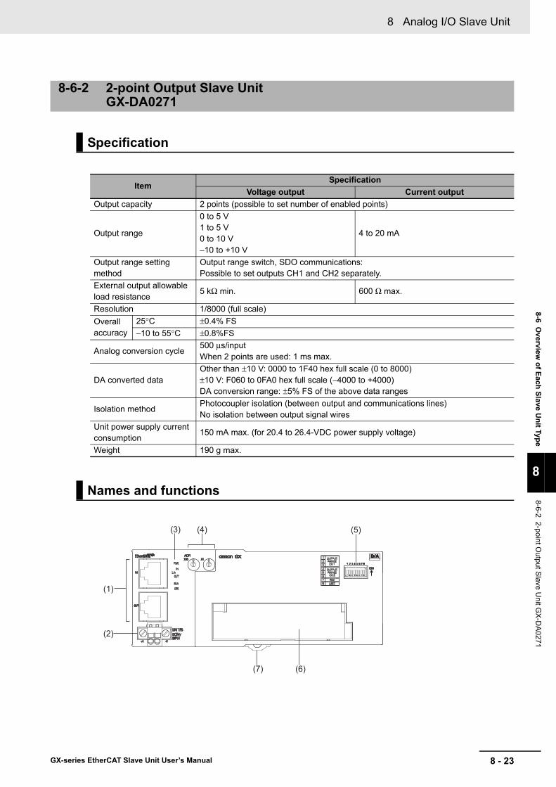
8 - 23
8 Analog I/O Slave Unit
GX-series EtherCAT Slave Unit User’s Manual
8-6 Overview
of Each Slave Unit Type
8
8-6-2 2-point Output Slave U
nit GX
-DA
0271
8-6-2 2-point Output Slave Unit GX-DA0271
Specification
ItemSpecification
Voltage output Current outputOutput capacity 2 points (possible to set number of enabled points)
Output range
0 to 5 V1 to 5 V0 to 10 V−10 to +10 V
4 to 20 mA
Output range setting method
Output range switch, SDO communications: Possible to set outputs CH1 and CH2 separately.
External output allowable load resistance
5 kΩ min. 600 Ω max.
Resolution 1/8000 (full scale)Overall accuracy
25°C ±0.4% FS−10 to 55°C ±0.8%FS
Analog conversion cycle500 μs/inputWhen 2 points are used: 1 ms max.
DA converted dataOther than ±10 V: 0000 to 1F40 hex full scale (0 to 8000)±10 V: F060 to 0FA0 hex full scale (−4000 to +4000)DA conversion range: ±5% FS of the above data ranges
Isolation methodPhotocoupler isolation (between output and communications lines)No isolation between output signal wires
Unit power supply current consumption
150 mA max. (for 20.4 to 26.4-VDC power supply voltage)
Weight 190 g max.
Names and functions
(1)
(6)
(2)
(3) (4)
(7)
(5)

8 Analog I/O Slave Unit
8 - 24 GX-series EtherCAT Slave Unit User’s Manual
Terminal arrangement diagram
• Output range setting switchesSet output range by combination of individual DIP switches.To enable settings of these switches, it is necessary to turn Pin8 (output range setting method) ON in advance.
Precautions for Correct Use
• Pin7 must be used in the OFF state.• To set a range using these switches, make sure to turn Pin8 ON. If it is turned OFF, the DIP
switch settings will not be reflected.• The settings of this switch are read only once when the power is turned ON.
No. Name Function(1) Communications connectors
Refer to "Specifications of Common Areas" in Page 6 - 4.(2) Unit power supply connector(3) Status indicators(4) Node Address setting Switches
(5) Output range setting SwitchesDIP switches for setting output range (Refer to the following section.)
(6) Terminal block
Terminal block for analog output signalsV1+, V2+: Voltage output positive terminalsI1+, I2+: Current output positive terminals1−, 2−: Voltage/current output negative terminalsNC: Not used
(7) DIN track mounting hook Fixes a Slave Unit to a DIN track.
Pin No. Setting Specification1
Setting of output CH1 rangeSet by combination of DIP switches (see the next table)
234
Setting of output CH2 range56
7 Always OFFMake sure to keep it OFF.The operation cannot be guaranteed when it is set to ON.
8 Output range setting methodOFF: Setting by SDO communicationsON: Setting by these switches (Pin1 to Pin6)
V1+
I1+
V2+
I2+ NC
NC 1−
NC 2−
NC
NC NC NC NC
NC NC NC NC
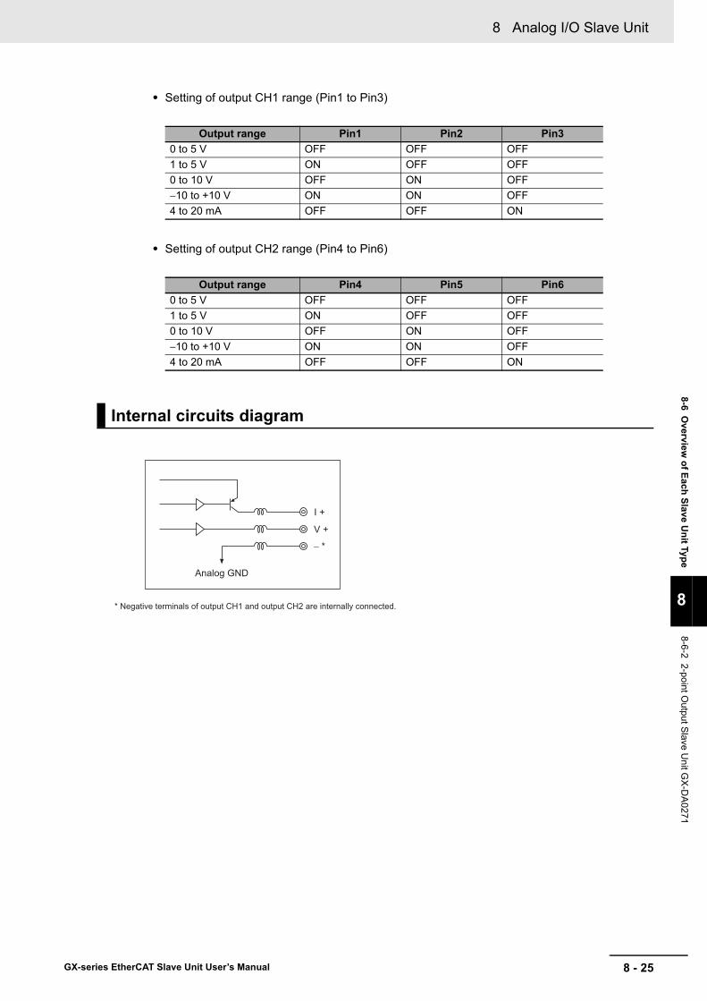
8 - 25
8 Analog I/O Slave Unit
GX-series EtherCAT Slave Unit User’s Manual
8-6 Overview
of Each Slave Unit Type
8
8-6-2 2-point Output Slave U
nit GX
-DA
0271
• Setting of output CH1 range (Pin1 to Pin3)
• Setting of output CH2 range (Pin4 to Pin6)
Output range Pin1 Pin2 Pin30 to 5 V OFF OFF OFF1 to 5 V ON OFF OFF0 to 10 V OFF ON OFF−10 to +10 V ON ON OFF4 to 20 mA OFF OFF ON
Output range Pin4 Pin5 Pin60 to 5 V OFF OFF OFF1 to 5 V ON OFF OFF0 to 10 V OFF ON OFF−10 to +10 V ON ON OFF4 to 20 mA OFF OFF ON
Internal circuits diagram
V +
I +
− *
Analog GND
* Negative terminals of output CH1 and output CH2 are internally connected.
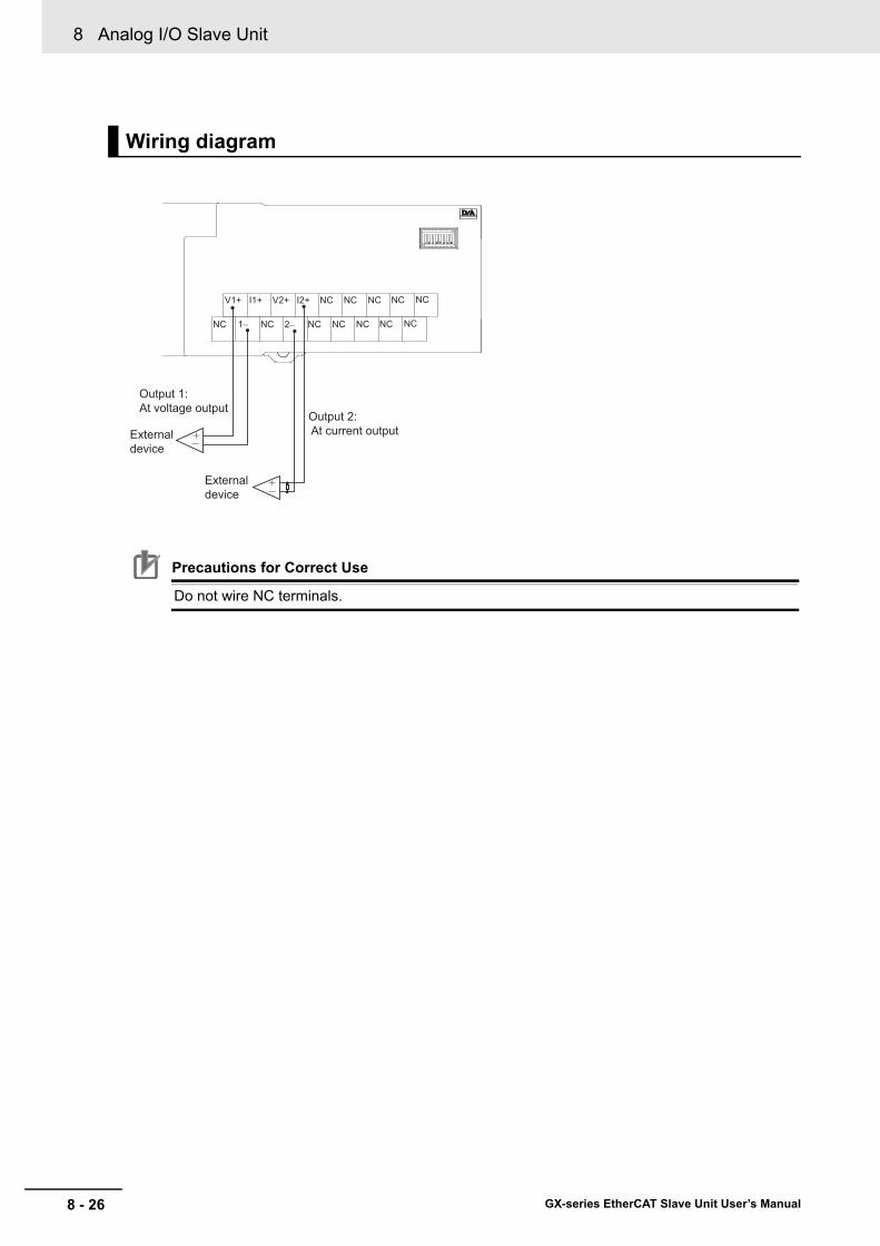
8 Analog I/O Slave Unit
8 - 26 GX-series EtherCAT Slave Unit User’s Manual
Precautions for Correct Use
Do not wire NC terminals.
Wiring diagram
External device
Output 1: At voltage output
External device
Output 2: At current output
V1+ I1+ V2+ I2+ NC NC NC NC NC
NC 1− NC 2− NC NC NC NC NC
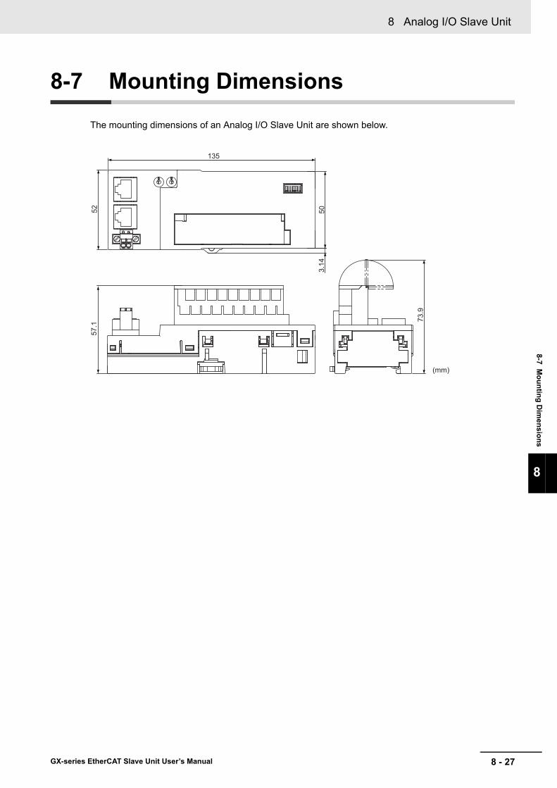
8 - 27
8 Analog I/O Slave Unit
GX-series EtherCAT Slave Unit User’s Manual
8-7 Mounting D
imensions
8
8-7 Mounting Dimensions
The mounting dimensions of an Analog I/O Slave Unit are shown below.
73.9
50
135
52
3.14
57.1
(mm)

8 Analog I/O Slave Unit
8 - 28 GX-series EtherCAT Slave Unit User’s Manual

9 - 1
9
GX-series EtherCAT Slave Unit User’s Manual
This chapter explains the overview of Encoder Input Slave Unit.
9-1 Encoder Input Slave Unit . . . . . . . . . . . . . . . . . . . . . . . . . . . . . . . . . . . . . . . . 9-29-2 I/O Data Allocation . . . . . . . . . . . . . . . . . . . . . . . . . . . . . . . . . . . . . . . . . . . . . 9-3
9-2-1 Input Data Allocation . . . . . . . . . . . . . . . . . . . . . . . . . . . . . . . . . . . . . . . . . . . . . 9-39-2-2 Output Data Allocation . . . . . . . . . . . . . . . . . . . . . . . . . . . . . . . . . . . . . . . . . . . 9-6
9-3 Function of the Encoder Input Slave Units . . . . . . . . . . . . . . . . . . . . . . . . . 9-89-3-1 Count Mode . . . . . . . . . . . . . . . . . . . . . . . . . . . . . . . . . . . . . . . . . . . . . . . . . . . 9-89-3-2 Circular Counter . . . . . . . . . . . . . . . . . . . . . . . . . . . . . . . . . . . . . . . . . . . . . . . . 9-89-3-3 Input Signal Types . . . . . . . . . . . . . . . . . . . . . . . . . . . . . . . . . . . . . . . . . . . . . . 9-99-3-4 Encoder Direction Setting . . . . . . . . . . . . . . . . . . . . . . . . . . . . . . . . . . . . . . . . .9-119-3-5 Counter Reset . . . . . . . . . . . . . . . . . . . . . . . . . . . . . . . . . . . . . . . . . . . . . . . . . 9-129-3-6 Counter Preset . . . . . . . . . . . . . . . . . . . . . . . . . . . . . . . . . . . . . . . . . . . . . . . . 9-139-3-7 Counter value latch . . . . . . . . . . . . . . . . . . . . . . . . . . . . . . . . . . . . . . . . . . . . . 9-13
9-4 Specifications for Each Slave Unit . . . . . . . . . . . . . . . . . . . . . . . . . . . . . . . 9-149-4-1 Open collector input type GX-EC0211 . . . . . . . . . . . . . . . . . . . . . . . . . . . . . . 9-159-4-2 Line Driver Input Type GX-EC0241 . . . . . . . . . . . . . . . . . . . . . . . . . . . . . . . . 9-23
9-5 Mounting Dimensions . . . . . . . . . . . . . . . . . . . . . . . . . . . . . . . . . . . . . . . . . 9-30
Encoder Input Slave Unit
9 Encoder Input Slave Unit
9 - 2 GX-series EtherCAT Slave Unit User’s Manual
9-1 Encoder Input Slave Unit
An Encoder Input Slave Unit has 5 V and 24 V open collector input function or line driver input function.The open collector input can be measured up to 500 kHz and the line driver input up to 4 MHz.

9 - 3
9 Encoder Input Slave Unit
GX-series EtherCAT Slave Unit User’s Manual
9-2 I/O D
ata Allocation
9
9-2-1 Input Data A
llocation
9-2 I/O Data Allocation
I/O data of Encoder Input Slave Units are allocated to the input/output areas of the I/O memory of the EtherCAT Master Unit, respectively.
Also, the Sysmac error status is allocated to the IN area of I/O memory of the EtherCAT Master Unit. *1
The ESI file are used to allocate I/O data.For the detailed explanation of allocation method, refer to the manual of EtherCAT Master Unit to be connected.*1 Unit version 1.1 or later only.
Encoder Input Slave Unit stores the counter present value, external latch value A, external latch value B and the counter status as input data, and can allocate required data to Input area.The details of each data type are as follows.
*1 Unit version 1.1 or later only.
9-2-1 Input Data Allocation
Data Size DetailCounter present value 8 bytes Used to monitor counter data.External latch value A 8 bytes Stores the counter value (latch value A) latched by external latch A.External latch value B 8 bytes Stores the counter value (latch value B) latched by external latch B.Counter status 2 bytes Status flag to check the counter status.
Sysmac error status *1 1 byte Status flags that show Slave Unit errors and connection confirmation.

9 Encoder Input Slave Unit
9 - 4 GX-series EtherCAT Slave Unit User’s Manual
The data allocation is as follows when using the default settings.
Counter status + counter present value data + external latch A data + external latch B data (size = 26 bytes)
Offset(byte) D07 D06 D05 D04 D03 D02 D01 D00
0 CRUN1 CERR1 Reserved EXLB1 EXLA1 EXRES1 RACK1 PACK1
+1 CRUN2 CERR2 Reserved EXLB2 EXLA2 EXRES2 RACK2 PACK2
+2
CH1 Present value data
(LL)
+3 (LH)
+4 (HL)
+5 (HH)
+6
CH2 Present value data
(LL)
+7 (LH)
+8 (HL)
+9 (HH)
+10
CH1 Latch A data
(LL)
+11 (LH)
+12 (HL)
+13 (HH)
+14
CH2 Latch A data
(LL)
+15 (LH)
+16 (HL)
+17 (HH)
+18
CH1 Latch B data
(LL)
+19 (LH)
+20 (HL)
+21 (HH)
+22
CH2 Latch B data
(LL)
+23 (LH)
+24 (HL)
+25 (HH)
0 to +1: Counter status

9 - 5
9 Encoder Input Slave Unit
GX-series EtherCAT Slave Unit User’s Manual
9-2 I/O D
ata Allocation
9
9-2-1 Input Data A
llocation
Counter status + counter present value data + external latch A data + external latch B data + Sysmac error status (size = 27 bytes)
Offset(byte) D07 D06 D05 D04 D03 D02 D01 D00
0 CRUN1 CERR1 Reserved EXLB1 EXLA1 EXRES1 RACK1 PACK1
+1 CRUN2 CERR2 Reserved EXLB2 EXLA2 EXRES2 RACK2 PACK2
+2
CH1 Present value data
(LL)
+3 (LH)
+4 (HL)
+5 (HH)
+6
CH2 Present value data
(LL)
+7 (LH)
+8 (HL)
+9 (HH)
+10
CH1 Latch A data
(LL)
+11 (LH)
+12 (HL)
+13 (HH)
+14
CH2 Latch A data
(LL)
+15 (LH)
+16 (HL)
+17 (HH)
+18
CH1 Latch B data
(LL)
+19 (LH)
+20 (HL)
+21 (HH)
+22
CH2 Latch B data
(LL)
+23 (LH)
+24 (HL)
+25 (HH)
+26 Sysmac error status
0 to +1: Counter status
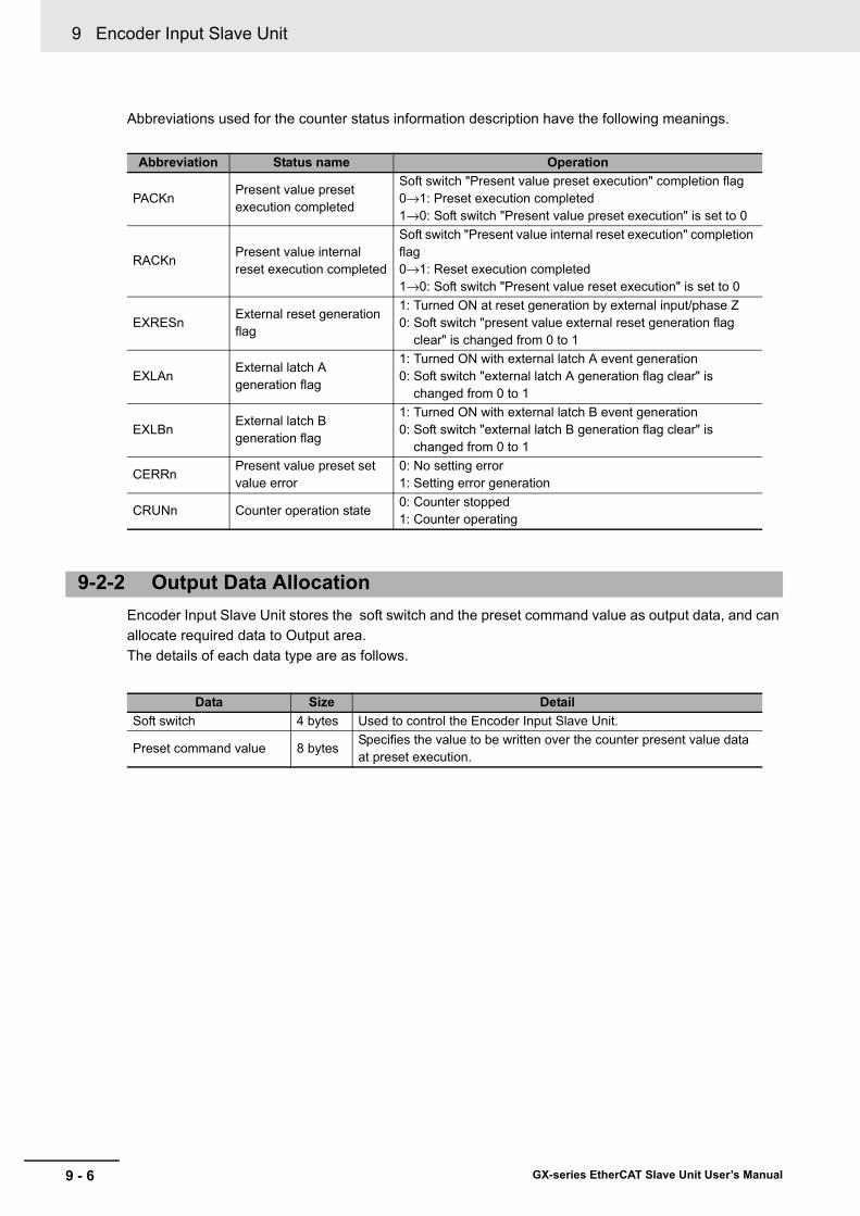
9 Encoder Input Slave Unit
9 - 6 GX-series EtherCAT Slave Unit User’s Manual
Abbreviations used for the counter status information description have the following meanings.
Encoder Input Slave Unit stores the soft switch and the preset command value as output data, and can allocate required data to Output area.The details of each data type are as follows.
Abbreviation Status name Operation
PACKnPresent value preset execution completed
Soft switch "Present value preset execution" completion flag0→1: Preset execution completed1→0: Soft switch "Present value preset execution" is set to 0
RACKnPresent value internal reset execution completed
Soft switch "Present value internal reset execution" completion flag0→1: Reset execution completed1→0: Soft switch "Present value reset execution" is set to 0
EXRESnExternal reset generation flag
1: Turned ON at reset generation by external input/phase Z0: Soft switch "present value external reset generation flag
clear" is changed from 0 to 1
EXLAnExternal latch A generation flag
1: Turned ON with external latch A event generation0: Soft switch "external latch A generation flag clear" is
changed from 0 to 1
EXLBnExternal latch B generation flag
1: Turned ON with external latch B event generation0: Soft switch "external latch B generation flag clear" is
changed from 0 to 1
CERRnPresent value preset set value error
0: No setting error1: Setting error generation
CRUNn Counter operation state0: Counter stopped1: Counter operating
9-2-2 Output Data Allocation
Data Size DetailSoft switch 4 bytes Used to control the Encoder Input Slave Unit.
Preset command value 8 bytesSpecifies the value to be written over the counter present value data at preset execution.

9 - 7
9 Encoder Input Slave Unit
GX-series EtherCAT Slave Unit User’s Manual
9-2 I/O D
ata Allocation
9
9-2-2 Output D
ata Allocation
The data allocation is as follows when using the default settings.
Soft switch + preset command value (size = 12 bytes)
Abbreviations used in soft switch description have the following meanings.
Offset(byte) D07 D06 D05 D04 D03 D02 D01 D00
0 Reserved Reserved Reserved Reserved Reserved INPRES1 PSET1 CENB1
+1 Reserved EXLBC1 EXLAC1 EXRESC1 Reserved EXLBE1 EXLAE1 EXRESE1
+2 Reserved Reserved Reserved Reserved Reserved INPRES2 PSET2 CENB2
+3 Reserved EXLBC2 EXLAC2 EXRESC2 Reserved EXLBE2 EXLAE2 EXRESE2
+4 (LL)
+5 CH1 Preset command value (LH)
+6 (HL)
+7 (HH)
+8 (LL)
+9 CH2 Preset command value (LH)
+10 (HL)
+11 (HH)
0 to +3: Soft switch
Abbreviation Status name Operation Detection
CENBnCount possible/not possible
1: Count possible command0: Count not possible command
Level
PSETnPresent value preset execution
0→1: Start preset of present value1→0: Clear present value preset execution completion
flagEdge
INPRESnPresent value internal reset execution
0→1: Start resetting present value1→0: Clear present value internal reset execution
completion flagEdge
EXRESEnPresent value external reset enabled
1: Enabled0: Disabled
Level
EXLAEn External latch A enabled1: Enabled0: Disabled
Level
EXLBEn External latch B enabled1: Enabled0: Disabled
Level
EXRESCnClear present value external reset generation flag
0→1: Clear flag Edge
EXLACnClear external latch A generation flag
0→1: Clear flag Edge
EXLBCnClear external latch B generation flag
0→1: Clear flag Edge

9 Encoder Input Slave Unit
9 - 8 GX-series EtherCAT Slave Unit User’s Manual
9-3 Function of the Encoder Input Slave Units
This section explains the function of Encoder Input Slave Units.
The Count Mode is run by the Circular Counter.
Set the maximum Circular Counter value and perform incremental/decremental count in the range from 0 to the maximum value or from the maximum value to 0.The maximum value can be set in the range from 1 to 4,294,967,295 (FFFFFFFF hex).Note that if 0 is set, the maximum value becomes FFFFFFFF hex.
If the counter value exceeds the maximum value, the counter value returns to 0 to continue count operation.If the counter value becomes less than 0, the counter value returns to the maximum value to continue count operation.
The settings are made using the SDO communications.The target index is 4003 hex.For the details, refer to the information in the corresponding index of "Appendix A-1 Object Dictionary" in Page A - 47.
There are the following two methods to restart the counter.• Cycle the power supply.• Change the CENBn software switch (Count Possible/Not Possible) from 0 to 1.
9-3-1 Count Mode
9-3-2 Circular Counter
Setting method
0(00000000 hex)
1 ≤ maximum value ≤ 4,294,967,295(00000001 hex ≤ maximum value ≤ 0xFFFFFFFF hex)
Incremental count Decremental count
Count continuously
counter value
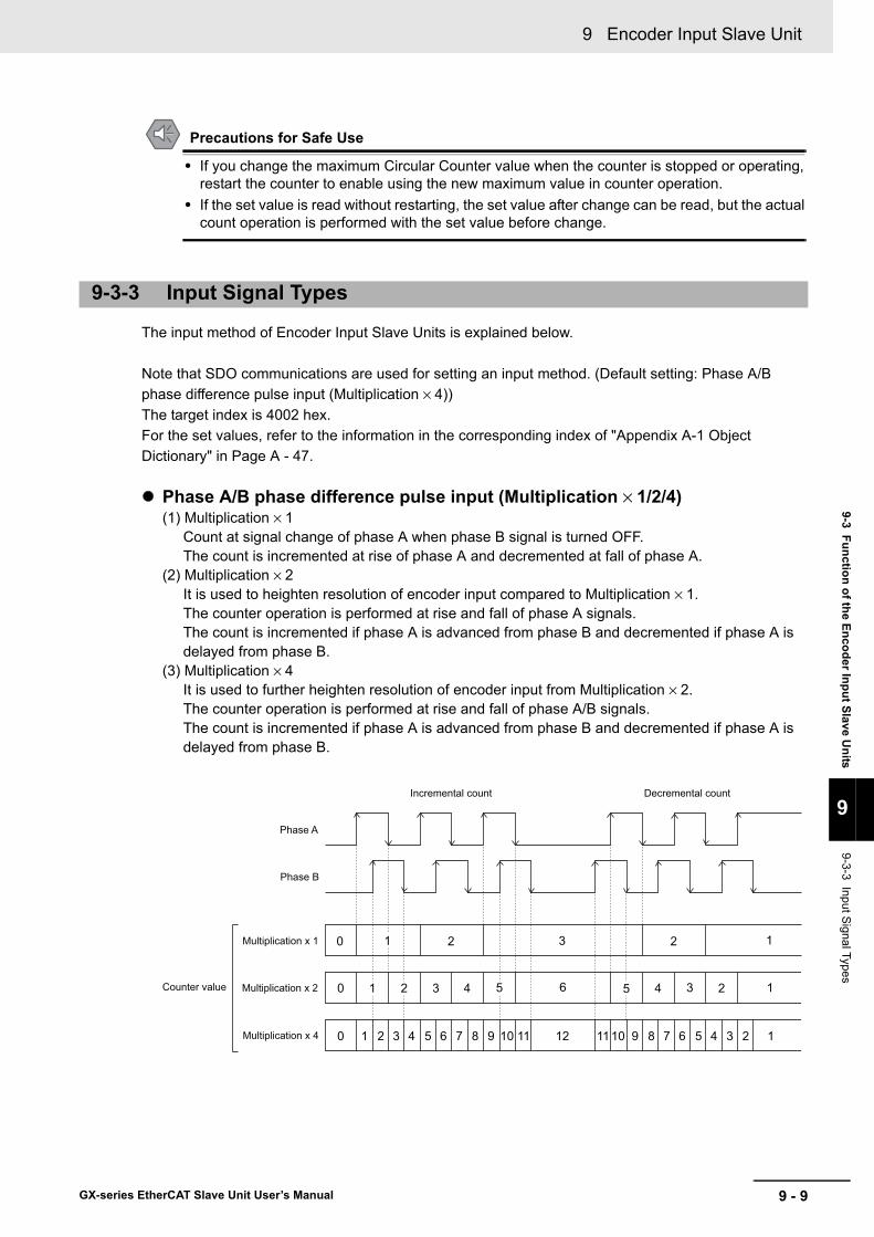
9 - 9
9 Encoder Input Slave Unit
GX-series EtherCAT Slave Unit User’s Manual
9-3 Function of the Encoder Input Slave Units
9
9-3-3 Input Signal Types
Precautions for Safe Use
• If you change the maximum Circular Counter value when the counter is stopped or operating, restart the counter to enable using the new maximum value in counter operation.
• If the set value is read without restarting, the set value after change can be read, but the actual count operation is performed with the set value before change.
The input method of Encoder Input Slave Units is explained below.
Note that SDO communications are used for setting an input method. (Default setting: Phase A/B phase difference pulse input (Multiplication × 4))The target index is 4002 hex.For the set values, refer to the information in the corresponding index of "Appendix A-1 Object Dictionary" in Page A - 47.
Phase A/B phase difference pulse input (Multiplication × 1/2/4)(1) Multiplication × 1
Count at signal change of phase A when phase B signal is turned OFF.The count is incremented at rise of phase A and decremented at fall of phase A.
(2) Multiplication × 2It is used to heighten resolution of encoder input compared to Multiplication × 1.The counter operation is performed at rise and fall of phase A signals.The count is incremented if phase A is advanced from phase B and decremented if phase A is delayed from phase B.
(3) Multiplication × 4It is used to further heighten resolution of encoder input from Multiplication × 2.The counter operation is performed at rise and fall of phase A/B signals.The count is incremented if phase A is advanced from phase B and decremented if phase A is delayed from phase B.
9-3-3 Input Signal Types
Phase A
Incremental count Decremental count
Multiplication x 1
Multiplication x 2
Multiplication x 4
Phase B
Counter value
0 1 2 3 4 5 6 7 8 9 10 11 12 9 8 7 6 5 4 3 2 11011
0 1
3
4
0
125 342 3 5 6
1 22 1

9 Encoder Input Slave Unit
9 - 10 GX-series EtherCAT Slave Unit User’s Manual
When phase A/B phase difference pulse is input, the connection with external input devices becomes as follows.
Code + pulse inputInput A is count pulse signal and input B is count direction control signal.The count is incremented at rise of phase A when input B is ON and decremented at rise of phase A when input B is OFF.
When code and pulses are input, the connection with external input devices becomes as follows.
Incremental/decremental pulse inputThe count is incremented at rise of input A pulse and decremented at rise of input B pulse.
Encoder
A
B
Z(Reset Input)
Input A
Input B
Input Z
Encoder Input Slave Unit
Counter value 0 1 2 3 4 5 6 7 8 07 6 5 4 3 2 1
Incremental count Decremental count
Count pulse signalInput A
Count direction control signal
Input B
Encoder or other pulse generators Count pulse
Input A
Input B
Input Z
Encoder Input Slave Unit
Count directioncontrol
Sensor orswitch
Input A
Input B
Counter value 0 1 2 3 4 5 6 7 8 07 6 5 4 3 2 1
Incremental count Decremental count
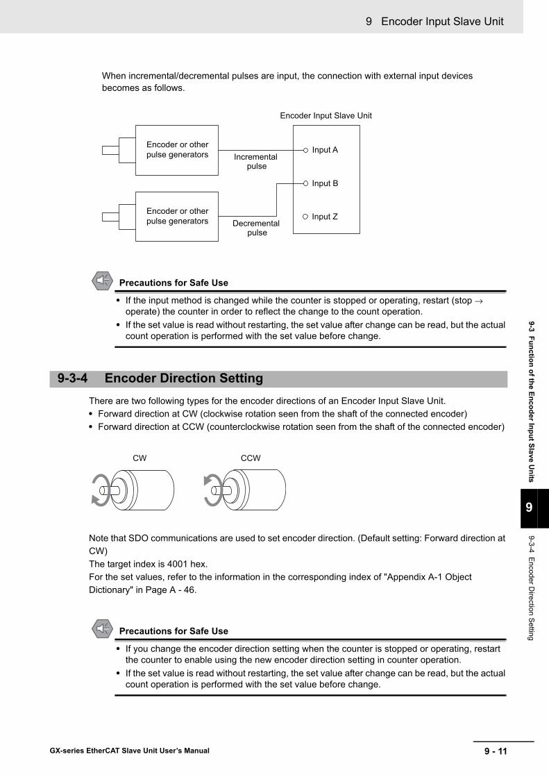
9 - 11
9 Encoder Input Slave Unit
GX-series EtherCAT Slave Unit User’s Manual
9-3 Function of the Encoder Input Slave Units
9
9-3-4 Encoder D
irection Setting
When incremental/decremental pulses are input, the connection with external input devices becomes as follows.
Precautions for Safe Use
• If the input method is changed while the counter is stopped or operating, restart (stop → operate) the counter in order to reflect the change to the count operation.
• If the set value is read without restarting, the set value after change can be read, but the actual count operation is performed with the set value before change.
There are two following types for the encoder directions of an Encoder Input Slave Unit.• Forward direction at CW (clockwise rotation seen from the shaft of the connected encoder)• Forward direction at CCW (counterclockwise rotation seen from the shaft of the connected encoder)
Note that SDO communications are used to set encoder direction. (Default setting: Forward direction at CW)The target index is 4001 hex.For the set values, refer to the information in the corresponding index of "Appendix A-1 Object Dictionary" in Page A - 46.
Precautions for Safe Use
• If you change the encoder direction setting when the counter is stopped or operating, restart the counter to enable using the new encoder direction setting in counter operation.
• If the set value is read without restarting, the set value after change can be read, but the actual count operation is performed with the set value before change.
9-3-4 Encoder Direction Setting
Encoder or other pulse generators Incremental
pulse
Input A
Input B
Input Z
Encoder Input Slave Unit
Encoder or other pulse generators Decremental
pulse
CW CCW

9 Encoder Input Slave Unit
9 - 12 GX-series EtherCAT Slave Unit User’s Manual
It is possible to reset counter value for each channel using the elements shown below.
Counter reset bitThe counter of each channel is reset to 0 by changing soft switch "present value internal reset execution" allocated to each channel from 0 to 1 in the output data (Slave Unit → EtherCAT Master Unit) area.
External control inputThe counter is reset to 0 at rise of the present value external reset input signal or phase Z input signal.However, it is necessary to set the soft switch "present value external reset enabled" to 1.
If the counter value is reset via input of the present value external reset or phase Z, the "external reset generation flag" is turned ON. By changing "clear present value external reset generation flag" from 0 to 1, "external reset generation flag" is cleared, enabling the next reset reception.
The counter reset conditions are shown in the figure below.
Precautions for Safe Use
While the counter function is stopped, external reset is disabled.For this reason, if the reset function is to be used while the counter function is stopped, use the present value internal reset execution (soft switch).
9-3-5 Counter Reset
OR
AND
OR
Preset value internal reset execution
[soft switch]
Resetexecution
Present value external reset input
[signal input]
Phase Z signal[signal input]
Present value external reset enabled
[soft switch]
Present value externalreset generation flag
[soft switch]
NOT

9 - 13
9 Encoder Input Slave Unit
GX-series EtherCAT Slave Unit User’s Manual
9-3 Function of the Encoder Input Slave Units
9
9-3-6 Counter P
reset
It is possible to preset counter value for each channel using the elements shown below.
Counter preset bitThe counter present value is overwritten by "preset command value" by changing soft switch "present value preset execution" allocated to each channel from 0 to 1 in the output data (Slave Unit → EtherCAT Master Unit) area.
Preset command valueSet "preset command value" allocated to each channel in output data (Slave Unit → EtherCAT Master Unit) area or via SDO communications. (Default setting: 0)When SDO communications are used, the target index is 4011 hex.For the details, refer to the information in the corresponding index of "Appendix A-1 Object Dictionary" in Page A - 47.
The counter value is latched for each channel using the elements shown below.It is possible to latch two values at the same time.
External control input (latch A)The present counter value is acquired/stored at the rise of latch A of external control input.However, it is necessary to set the soft switch "external latch A enabled" to "enabled." *
External control input (latch B)The present counter value is acquired/stored at the rise of latch B of external control input.However, it is necessary to set the soft switch "external latch B enabled" to "enabled." *
For both latch A and B inputs, when latch is generated via latch input, the "external latch generation flag" changes from 0 to 1 and the counter value is stored in objects (latch value A/latch value B) as latch A/latch B data.By changing "clear external latch generation flag" from 0 to 1, it is possible to clear the "external latch generation flag."When the "external latch generation flag" is cleared, the next latch input becomes enabled.
If it is desired to use latched counter values (latch values) in a ladder program, select PDO mapping to which latch data is allocated.
* To use SDO communications, acquire/store the present counter value at the rise of latch A/B of external control input, regardless of the status of the soft switch "external latch A/B enabled."
9-3-6 Counter Preset
9-3-7 Counter value latch

9 Encoder Input Slave Unit
9 - 14 GX-series EtherCAT Slave Unit User’s Manual
9-4 Specifications for Each Slave Unit
This section shows the specification of Encoder Input Slave Units, names and functions of each part, internal circuit diagram, and wiring diagram.Refer to the following corresponding page to each model.
Type Model
Reference page
Specification Names and functions
Internal circuits diagram
Wiring diagram
Open collector input type
GX-EC0211 9-15 9-17 9-20 9-21
Line driverInput type
GX-EC0241 9-23 9-25 9-28 9-29
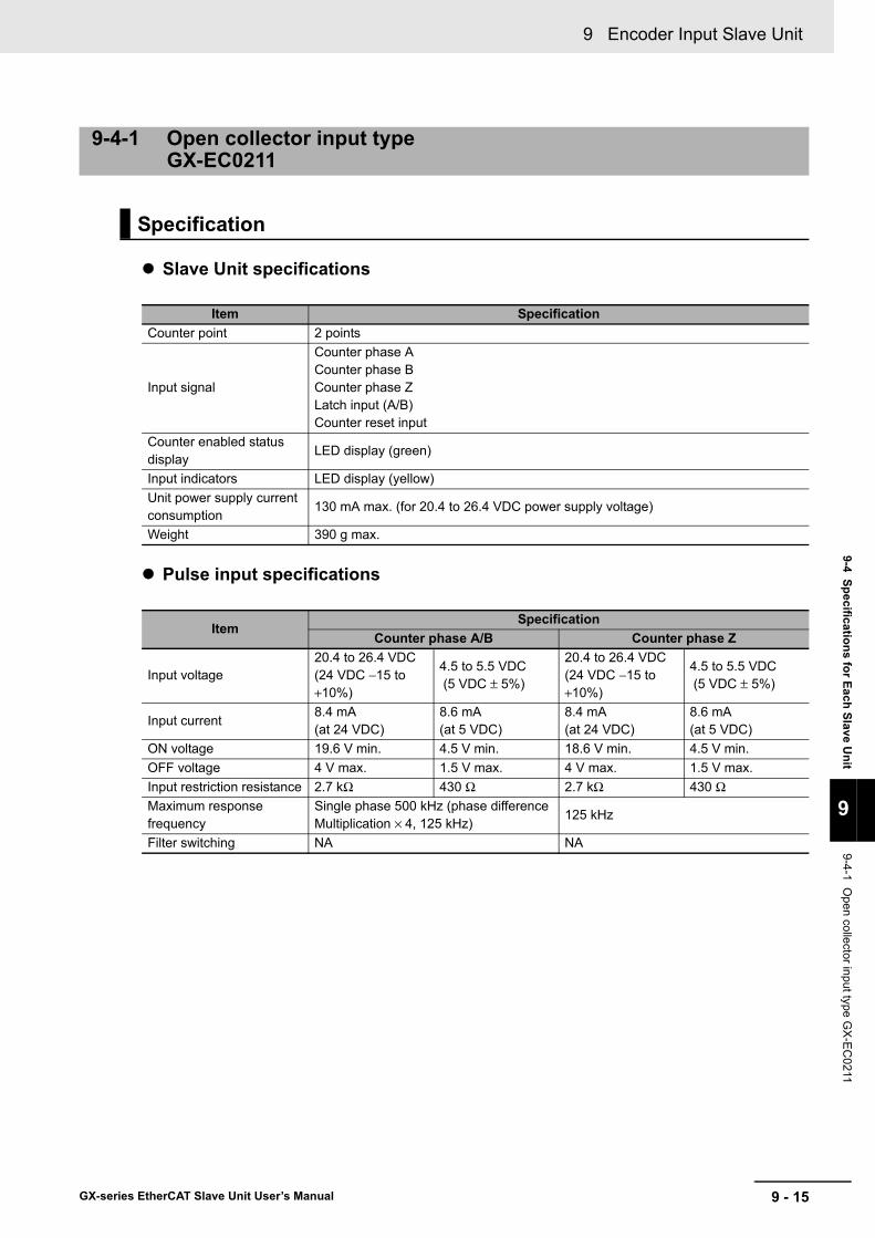
9 - 15
9 Encoder Input Slave Unit
GX-series EtherCAT Slave Unit User’s Manual
9-4 Specifications for Each Slave Unit
9
9-4-1 Open collector input type G
X-E
C0211
Slave Unit specifications
Pulse input specifications
9-4-1 Open collector input typeGX-EC0211
Specification
Item SpecificationCounter point 2 points
Input signal
Counter phase ACounter phase BCounter phase ZLatch input (A/B)Counter reset input
Counter enabled status display
LED display (green)
Input indicators LED display (yellow)Unit power supply current consumption
130 mA max. (for 20.4 to 26.4 VDC power supply voltage)
Weight 390 g max.
ItemSpecification
Counter phase A/B Counter phase Z
Input voltage20.4 to 26.4 VDC (24 VDC −15 to+10%)
4.5 to 5.5 VDC (5 VDC ± 5%)
20.4 to 26.4 VDC (24 VDC −15 to+10%)
4.5 to 5.5 VDC (5 VDC ± 5%)
Input current8.4 mA(at 24 VDC)
8.6 mA(at 5 VDC)
8.4 mA(at 24 VDC)
8.6 mA(at 5 VDC)
ON voltage 19.6 V min. 4.5 V min. 18.6 V min. 4.5 V min.OFF voltage 4 V max. 1.5 V max. 4 V max. 1.5 V max.Input restriction resistance 2.7 kΩ 430 Ω 2.7 kΩ 430 ΩMaximum response frequency
Single phase 500 kHz (phase difference Multiplication × 4, 125 kHz)
125 kHz
Filter switching NA NA

9 Encoder Input Slave Unit
9 - 16 GX-series EtherCAT Slave Unit User’s Manual
Pulse input timing specifications
Precautions for Correct Use
In order to satisfy the counter input specifications, it is necessary to pay attention to the type of output driver of the encoder to be used, the length of encoder cable, and frequency of count pulse.
Timing conditionA B C D E F G
<0.3 μs >1 μs >2 μs >4 μs >8 μs >2 μs >4 μs
C
BB
AA
ONvoltage
OFFvoltage
Terminalinput
G
AA
E
D
AA
Phase A
E
D
AA
Phase B
FF F F
Counter input phase A/BInput pulse duty: 50%
Counter input phase Z
Relationship between phase A and phase B at phase difference pulse input
Terminalinput
OFFvoltage
OFFvoltage
ONvoltage
ONvoltage
Terminalinput OFF
voltage

9 - 17
9 Encoder Input Slave Unit
GX-series EtherCAT Slave Unit User’s Manual
9-4 Specifications for Each Slave Unit
9
9-4-1 Open collector input type G
X-E
C0211
Latch/reset input specifications
Terminal/input display LED layout diagram
ItemSpecification
Latch input (A/B) Reset inputInternal I/O common NPNInput voltage 20.4 to 26.4 VDC (24 VDC −15 to +10%) 20.4 to 26.4 VDC (24 VDC −15 to +10%)Input impedance 4.0 kΩ 3.3 kΩInput current 5.5 mA (at 24 VDC) 7 mA (at 24 VDC)ON voltage/ON current 17.4 VDC min./3 mA min. 14.4 VDC min./3 mA min.OFF voltage/OFF current 5 VDC max./1 mA max. 5 VDC max./1 mA max.ON response time 3 μs max. 15 μs max.OFF response time 3 μs max. 90 μs max.
Names and functions
No. Name Function(1) Communications connectors
Refer to "6-3 Specifications of Common Areas" Page 6 - 4.(2) Unit power supply connector(3) Status indicators(4) Node address switches
(5) Input indicatorsThe indicators show the status of the inputs of each channel.For details, refer to the next section "Input indicators".
(6) Terminal blockConnects external devices and the I/O power supply.For details, refer to the next section "Terminal block".
(7) DIN track mounting hook Fixes a Slave Unit to a DIN track.
(1)
(2)
(3) (4) (5)
(6)(7)
10 to 18
1 to 9
19 to 27
A24
LB1RSV V1 V1 V1
V1 V1
RST1
V2 V2 V2 V2
G1 G1 A5 B5 Z5 G2 G2 G2 G2
RSV
B24 Z24
RSV LA1
CH1 A1 B1 Z1 LA1 LB1 RST1
CH1 CH2
A24
LB2RSV V1 V1 V1
V1 V1
RST2
V2 V2 V2 V2
G1 G1 A5 B5 Z5 G2 G2 G2 G2
RSV
B24 Z24
RSV LA2
CH2 A2 B2 Z2 LA2 LB2 RST2

9 Encoder Input Slave Unit
9 - 18 GX-series EtherCAT Slave Unit User’s Manual
• Input indicators
CH1 CH2Name State Contents Name State Contents
CH1Lit green. Counter operating
CH2Lit green. Counter operating
OFF Counter stopped OFF Counter stopped
A1
Lit yellow.
Input A (phase A signal/count pulse signal/incremental count signal) available
A2
Lit yellow.
Input A (phase A signal/count pulse signal/incremental count signal) available
OFFInput A (phase A signal/count pulse signal/incremental count signal) not available
OFFInput A (phase A signal/count pulse signal/incremental count signal) not available
B1
Lit yellow.
Input B (phase B signal/count direction control signal/decremental count signal) available
B2
Lit yellow.
Input B (phase B signal/count direction control signal/decremental count signal) available
OFF
Input B (phase B signal/count direction control signal/decremental count signal) not available
OFF
Input B (phase B signal/count direction control signal/decremental count signal) not available
Z1Lit yellow.
Phase Z input availableZ2
Lit yellow.
Phase Z input available
OFF Phase Z input not available OFF Phase Z input not available
LA1
Lit yellow.
External latch input A availableLA2
Lit yellow.
External latch input A available
OFFExternal latch input A not available
OFFExternal latch input A not available
LB1
Lit yellow.
External latch input B availableLB2
Lit yellow.
External latch input B available
OFFExternal latch input B not available
OFFExternal latch input B not available
RST1Lit yellow.
External reset input availableRST2
Lit yellow.
External reset input available
OFF External reset input not available OFF External reset input not available

9 - 19
9 Encoder Input Slave Unit
GX-series EtherCAT Slave Unit User’s Manual
9-4 Specifications for Each Slave Unit
9
9-4-1 Open collector input type G
X-E
C0211
• Terminal block
CHTerminal
block number
Terminal name Contents
CH1CH2
1 RSV -2 RSV -
3 V1Encoder power supply input (power supply input at twisted-pair wiring)
4 V1Encoder power supply input (power supply input at twisted-pair wiring)
5 V1Encoder power supply input (power supply input at twisted-pair wiring)
6 RSV -7 LA1/LA2 Latch A input8 LB1/LB2 Latch B input9 RST1/RST2 Reset input10 V1 Encoder power supply input11 V1 Encoder power supply output12 A24 Phase A input (24 V)13 B24 Phase B input (24 V)14 Z24 Phase Z input (24 V)15 V2 Sensor power supply input16 V2 Sensor power supply output17 V2 Sensor power supply output18 V2 Sensor power supply output19 G1 Encoder power supply input20 G1 Encoder power supply output21 A5 Phase A input (5 V)22 B5 Phase B input (5 V)23 Z5 Phase Z input (5 V)24 G2 Sensor power supply input25 G2 Sensor power supply output26 G2 Sensor power supply output27 G2 Sensor power supply output
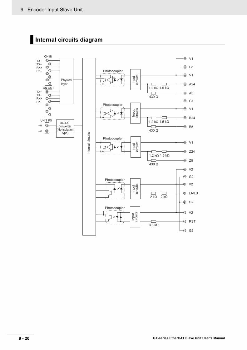
9 Encoder Input Slave Unit
9 - 20 GX-series EtherCAT Slave Unit User’s Manual
Internal circuits diagram
V1
A24
A5
G1
V1
B24
B5
V1
Z24
Z5
V1
G1
G2
V2
V2
LA/LB
G2
1.2 kΩ 1.5 kΩ
430 Ω
1.2 kΩ 1.5 kΩ
430 Ω
1.2 kΩ 1.5 kΩ
430 Ω
2 kΩ 2 kΩ
V2
RST
G2
3.3 kΩ
Photocoupler
Inte
rnal
circ
uits
Photocoupler
Photocoupler
Photocoupler
Photocoupler
Inpu
tci
rcui
tsIn
put
circ
uits
Inpu
tci
rcui
tsIn
put
circ
uits
Inpu
tci
rcui
ts
TX+
Physical layer
DC-DC converter
(No-isolationtype)
TX−RX+RX−
TX+TX−RX+RX−
CN IN
CN OUT
UNIT PS
+V
−V

9 - 21
9 Encoder Input Slave Unit
GX-series EtherCAT Slave Unit User’s Manual
9-4 Specifications for Each Slave Unit
9
9-4-1 Open collector input type G
X-E
C0211
Wiring diagram
RSV RSV V1 V1 V1 RSV LA1 LB1 RST1
V1 V1 A24 B24 Z24 V2 V2 V2
G1 G1 A5 B5 Z5 G2 G2 G2
V2
G2
Encoder power supply(24 VDC or 5 VDC)
Blue:0V
Brown:Vcc
Black:Phase A
White:Phase B
Orange:Phase Z
Encoder(NPN open collector
output type)
Black
Blue
Latch
Sensor power supply(24 VDC)
RSV RSV V1 V1 V1 RSV LA2 LB2 RST2
V1 V1 A24 B24 Z24 V2 V2 V2
G1 G1 A5 B5 Z5 G2 G2 G2
V2
G2
Black
Brow
nB
lue
NPN output 3-wire sensor
Latch
Black
Blue
Reset
Black
Blue
Latch
Output 2-wire sensor
Encoder(NPN open collector
output type)
Blue:0V
Brown:Vcc
Black:Phase A
White:Phase B
Orange:Phase Z
Black
Brow
nB
lue
Reset
Black
Brow
nB
lue
Latch

9 Encoder Input Slave Unit
9 - 22 GX-series EtherCAT Slave Unit User’s Manual
Precautions for Correct Use
• Use shielded cable and ground the shield to 100 Ω or less when wiring pulse input A/B/Z with external control inputs.
• Wiring of pulse input A/B/Z shall be as short as possible and separated from wiring with many noises such as power lines.
• Use stabilizing power supply separate from other inputs/outputs for Encoder Input Slave Units as much as possible.
• Do not wire anything to RSV terminals.
RSV RSV V1 V1 V1 RSV LA1 LB1 RST1
V1 V1 A24 B24 Z24 V2 V2 V2
G1 G1 A5 B5 Z5 G2 G2 G2
V2
G2
RSV RSV V1 V1 V1 RSV LA2 LB2 RST2
V1 V1 A24 B24 Z24 V2 V2 V2
G1 G1 A5 B5 Z5 G2 G2 G2
V2
G2
PhaseA
Black
Blue
Latch
Black
Blue
Reset
Black
Blue
Latch
PhaseB
PhaseZ
Encoder power supply(24 VDC or 5 VDC)
Blue: 0VBrown: Vcc
Black: Phase AWhite: Phase BOrange: Phase Z
Encoder(NPN open collector
output type)
Sensor power supply(24 VDC)
NPN output 3-wire sensor
Output 2-wire sensorEncoder
(NPN open collectoroutput type)
Black
Brow
nB
lue
Latch
Black
Brow
nB
lue
Latch
Black
Brow
nB
lue
Reset

9 - 23
9 Encoder Input Slave Unit
GX-series EtherCAT Slave Unit User’s Manual
9-4 Specifications for Each Slave Unit
9
9-4-2 Line Driver Input Type G
X-EC
0241
Slave Unit specifications
Pulse input specifications
9-4-2 Line Driver Input TypeGX-EC0241
Specification
Item SpecificationCounter point 2 points
Input signal
Counter phase ACounter phase BCounter phase ZLatch input (A/B)Counter reset input
Counter enabled status display
LED display (green)
Input indicators LED display (yellow)Unit power supply current consumption
100 mA max. (for 20.4 to 26.4 VDC power supply voltage)
Weight 390 g max.
ItemSpecification
Counter phase A/B Counter phase ZInput voltage EIA standard RS-422-A line driver levelInput impedance 120 Ω ±5%gH level input voltage 0.1 VgL level input voltage -0.1 VHysteresis voltage 60 mVMaximum response frequency
Single phase 4 MHz (phase difference Multiplication × 4, 1 MHz)
1 MHz
Filter switching NA
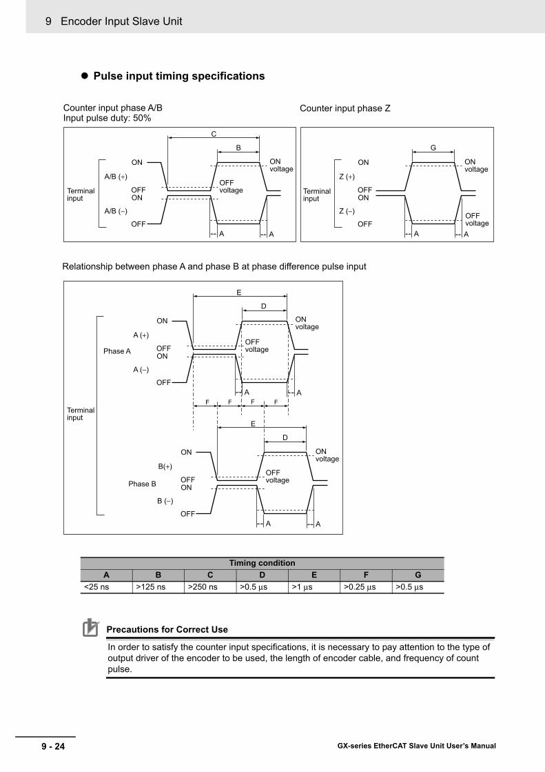
9 Encoder Input Slave Unit
9 - 24 GX-series EtherCAT Slave Unit User’s Manual
Pulse input timing specifications
Precautions for Correct Use
In order to satisfy the counter input specifications, it is necessary to pay attention to the type of output driver of the encoder to be used, the length of encoder cable, and frequency of count pulse.
Timing conditionA B C D E F G
<25 ns >125 ns >250 ns >0.5 μs >1 μs >0.25 μs >0.5 μs
C
B
FF FF
AA
ON
OFF
ONOFF
A/B (+)
A/B (−)
G
AA
ON
OFF
ONOFF
Z (+)
Z (−)
E
D
AA
ON
OFF
ONOFF
A (+)
A (−)
Phase A
E
D
AA
ON
OFF
ONOFF
B(+)
B (−)
Phase B
ONvoltage
Terminalinput
Counter input phase A/BInput pulse duty: 50%
Counter input phase Z
Relationship between phase A and phase B at phase difference pulse input
OFFvoltage Terminal
input
ONvoltage
OFFvoltage
Terminalinput
ONvoltage
ONvoltage
OFFvoltage
OFFvoltage

9 - 25
9 Encoder Input Slave Unit
GX-series EtherCAT Slave Unit User’s Manual
9-4 Specifications for Each Slave Unit
9
9-4-2 Line Driver Input Type G
X-EC
0241
Latch/reset input specifications
Terminal/input display LED layout diagram
ItemSpecification
Latch input (A/B) Reset inputInternal I/O common PNPInput voltage 20.4 to 26.4 VDC (24 VDC −15 to +10%) 20.4 to 26.4 VDC (24 VDC −15 to +10%)Input impedance 4.0 kΩ 3.3 kΩInput current 5.5 mA (at 24 VDC) 7 mA (at 24 VDC)ON voltage/ON current 17.4 VDC min./3 mA min. 14.4 VDC min./3 mA min.OFF voltage/OFF current 5 VDC max./1 mA max. 5 VDC max./1 mA max.ON response time 3 μs max. 15 μs max.OFF response time 3 μs max. 90 μs max.
Names and Functions
No. Name Function(1) Communications connectors
Refer to "6-3 Specifications of Common Areas" Page 6 - 4.(2) Unit power supply connector(3) Status indicators(4) Node address switches
(5) Input indicatorsThe indicators show the status of the inputs of each channel.For details, refer to the next section "Input indicators".
(6) Terminal blockConnects external devices and the I/O power supply.For details, refer to the next section "Terminal block".
(7) DIN track mounting hook Fixes a Slave Unit to a DIN track.
(1)
(2)
(3) (4) (5)
(6)(7)
10 to 18
1 to 9
19 to 27
LB1RSV RSV RSV RSV
V1 V1
RST1
V1 V1 V1 V1
G1 G1 G1 G1 G1 G1
RSV RSV LA1
CH1 A1 B1 Z1 LA1 LB1 RST1
CH1 CH2
RSV RSV RSV
A+
A− B− Z−
B+ Z+A+
A− B− Z−
B+ Z+
LB2RSV
V1 V1
RST2
V1 V1 V1 V1
G1 G1 G1 G1 G1 G1
RSV RSV LA2
CH2 A2 B2 Z2 LA2 LB2 RST2

9 Encoder Input Slave Unit
9 - 26 GX-series EtherCAT Slave Unit User’s Manual
• Input indicators
CH1 CH2Name State Contents Name State Contents
CH1Lit green. Counter operating
CH2Lit green. Counter operating
OFF Counter stopped OFF Counter stopped
A1
Lit yellow.
Input A (phase A signal/count pulse signal/incremental count signal) available
A2
Lit yellow.
Input A (phase A signal/count pulse signal/incremental count signal) available
OFFInput A (phase A signal/count pulse signal/incremental count signal) not available
OFFInput A (phase A signal/count pulse signal/incremental count signal) not available
B1
Lit yellow.
Input B (phase B signal/count direction control signal/decremental count signal) available
B2
Lit yellow.
Input B (phase B signal/count direction control signal/decremental count signal) available
OFF
Input B (phase B signal/count direction control signal/decremental count signal) not available
OFF
Input B (phase B signal/count direction control signal/decremental count signal) not available
Z1Lit yellow.
Phase Z input availableZ2
Lit yellow.
Phase Z input available
OFF Phase Z input not available OFF Phase Z input not available
LA1
Lit yellow.
External latch input A availableLA2
Lit yellow.
External latch input A available
OFFExternal latch input A not available
OFFExternal latch input A not available
LB1
Lit yellow.
External latch input B availableLB2
Lit yellow.
External latch input B available
OFFExternal latch input B not available
OFFExternal latch input B not available
RST1Lit yellow.
External reset input availableRST2
Lit yellow.
External reset input available
OFF External reset input not available OFF External reset input not available
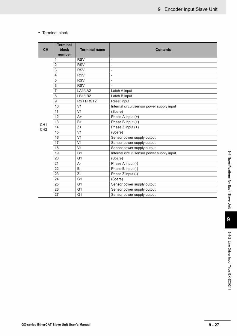
9 - 27
9 Encoder Input Slave Unit
GX-series EtherCAT Slave Unit User’s Manual
9-4 Specifications for Each Slave Unit
9
9-4-2 Line Driver Input Type G
X-EC
0241
• Terminal block
CHTerminal
block number
Terminal name Contents
CH1CH2
1 RSV -2 RSV -3 RSV -4 RSV -5 RSV -6 RSV -7 LA1/LA2 Latch A input8 LB1/LB2 Latch B input9 RST1/RST2 Reset input10 V1 Internal circuit/sensor power supply input11 V1 (Spare)12 A+ Phase A input (+)13 B+ Phase B input (+)14 Z+ Phase Z input (+)15 V1 (Spare)16 V1 Sensor power supply output17 V1 Sensor power supply output18 V1 Sensor power supply output19 G1 Internal circuit/sensor power supply input20 G1 (Spare)21 A- Phase A input (-)22 B- Phase B input (-)23 Z- Phase Z input (-)24 G1 (Spare)25 G1 Sensor power supply output26 G1 Sensor power supply output27 G1 Sensor power supply output
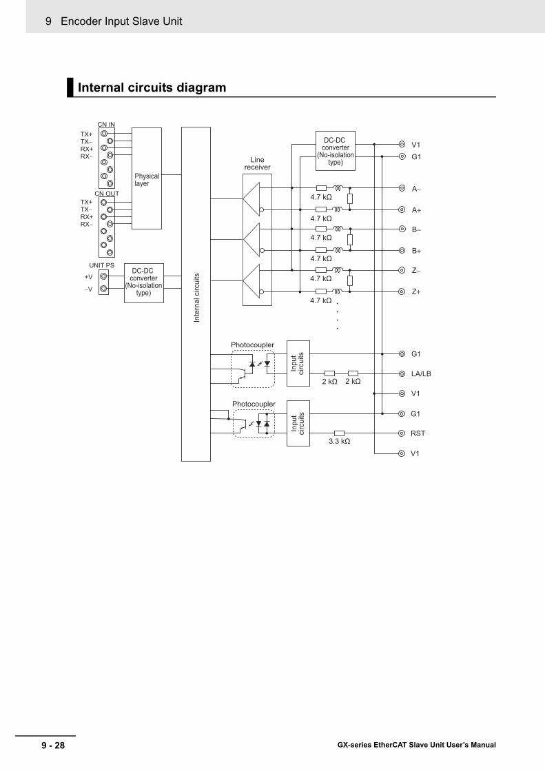
9 Encoder Input Slave Unit
9 - 28 GX-series EtherCAT Slave Unit User’s Manual
Internal circuits diagram
G1
LA/LB
V1
A−
A+
V1G1
B−
B+
Z−
Z+....
Linereceiver
2 kΩ 2 kΩ
4.7 kΩ
4.7 kΩ
4.7 kΩ
4.7 kΩ
4.7 kΩ
4.7 kΩ
G1
RST
V1
3.3 kΩ
Inte
rnal
circ
uits
Photocoupler
Photocoupler
Inpu
tci
rcui
tsIn
put
circ
uits
TX+
Physical layer
DC-DC converter
(No-isolationtype)
TX−RX+RX−
TX+TX−RX+RX−
CN IN
CN OUT
UNIT PS
+V
−V
DC-DC converter
(No-isolationtype)

9 - 29
9 Encoder Input Slave Unit
GX-series EtherCAT Slave Unit User’s Manual
9-4 Specifications for Each Slave Unit
9
9-4-2 Line Driver Input Type G
X-EC
0241
Precautions for Correct Use
• Use shielded cable and ground the shield to 100 Ω or less when wiring pulse input A/B/Z with external control inputs.
• Wiring of pulse input A/B/Z shall be as short as possible and separated from wiring with many noises such as power lines.
• Use stabilizing power supply separate from other inputs/outputs for Encoder Input Slave Units as much as possible.
• Do not wire anything to RSV terminals.
Wiring diagram
RSV RSV RSV RSV RSV RSV LA1 LB1 RST1
V1 V1 A+ B+ Z+ V1 V1 V1
G1 G1 A− B− Z− G1 G1 G1
V1
G1
RSV RSV RSV RSV RSV RSV LA2 LB2 RST2
V1 V1 A+ B+ Z+ V1 V1 V1
G1 G1 A− B− Z− G1 G1 G1
V1
G1
Encoder(Line driveroutput type)
Encoder power supply(5 VDC)
Blue: 0V
Brown: VccBlack: Phase A+ Black/Red: Phase A−
Internal circuit / sensor power supply
(24 VDC)
Encoder(Line driveroutput type)
White: Phase B+ White/Red: Phase B−
Orange: Phase Z+ Orange/Red: Phase Z−
Encoder power supply(5 VDC)
PhaseA
PhaseB
PhaseZ
Black
Blue
Latch
Black
Blue
Reset
Black
Blue
LatchOutput
2-wire sensorNPN output 3-wire sensor
Black
Brow
nB
lue
Latch
Black
Brow
nB
lue
Latch
Black
Brow
nB
lue
Reset
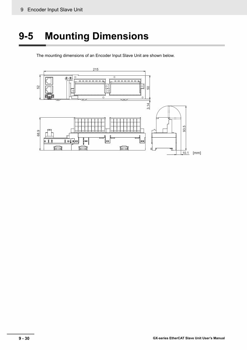
9 Encoder Input Slave Unit
9 - 30 GX-series EtherCAT Slave Unit User’s Manual
9-5 Mounting Dimensions
The mounting dimensions of an Encoder Input Slave Unit are shown below.
93.5
10.1
68.9
52
3.14
50
215
[mm]

10 - 1
10
GX-series EtherCAT Slave Unit User’s Manual
10-1 What Is an IO-Link Master Unit? . . . . . . . . . . . . . . . . . . . . . . . . . . . . . . . . . 10-210-1-1 Introduction . . . . . . . . . . . . . . . . . . . . . . . . . . . . . . . . . . . . . . . . . . . . . . . . . . . 10-210-1-2 Connection Configuration for EtherCAT Communications Master Unit and IO-Link
Devices . . . . . . . . . . . . . . . . . . . . . . . . . . . . . . . . . . . . . . . . . . . . . . . . . . . . . . 10-2
10-2 I/O Data Allocations: PDO Mapping . . . . . . . . . . . . . . . . . . . . . . . . . . . . . . 10-310-2-1 Allocating Input Data . . . . . . . . . . . . . . . . . . . . . . . . . . . . . . . . . . . . . . . . . . . . 10-310-2-2 Allocating Output Data . . . . . . . . . . . . . . . . . . . . . . . . . . . . . . . . . . . . . . . . . . 10-4
10-3 Functions of the IO-Link Master Unit . . . . . . . . . . . . . . . . . . . . . . . . . . . . . 10-510-4 Specifications . . . . . . . . . . . . . . . . . . . . . . . . . . . . . . . . . . . . . . . . . . . . . . . . 10-7
10-4-1 Specifications . . . . . . . . . . . . . . . . . . . . . . . . . . . . . . . . . . . . . . . . . . . . . . . . . 10-710-4-2 Part Names and Functions . . . . . . . . . . . . . . . . . . . . . . . . . . . . . . . . . . . . . . .10-11
10-5 Mounting Dimensions . . . . . . . . . . . . . . . . . . . . . . . . . . . . . . . . . . . . . . . . 10-1510-6 Communications Performance . . . . . . . . . . . . . . . . . . . . . . . . . . . . . . . . . 10-16
10-6-1 Maximum I/O Response Time . . . . . . . . . . . . . . . . . . . . . . . . . . . . . . . . . . . 10-1610-6-2 Determining the IO-Link Communications Cycle . . . . . . . . . . . . . . . . . . . . . 10-18
10-6 Communications Performance . . . . . . . . . . . . . . . . . . . . . . . . . . . . . . . . . 10-1610-7 Connected Device Specifications and Models . . . . . . . . . . . . . . . . . . . . 10-19
IO-Link Master Unit

10 IO-Link Master Unit
10 - 2 GX-series EtherCAT Slave Unit User’s Manual
10-1 What Is an IO-Link Master Unit?
An IO-Link Master Unit is a slave that has I/O processing functions for IO-Link communications with IO-Link devices and I/O processing functions for digital I/O data (ON/OFF signals) with non-IO_Link devices.For an IO-Link Master Unit, processing functions can be assigned for each port to combine different types of I/O processing functions.
Also, with IO-Link devices that support digital inputs with pin 2, the IO-Link Master Unit can simultaneously perform both IO-Link communications and receive digital inputs.
A GX-series IO-Link Master Unit connects to IO-Link devices and the EtherCAT Master Unit as shown below.
*1 Non-IO-Link devices can also be connected.
10-1-1 Introduction
10-1-2 Connection Configuration for EtherCAT Communications Master Unit and IO-Link Devices
GX-series IO-Link Master Unit
IO-Link communications(4 wires per device)
IO-Link devices*1 IO-Link devices*1
M12M12
EtherCAT EtherCAT
EtherCAT communications master
Port 1
Port 3
Port 5
Port 7
Port 2
Port 4
Port 6
Port 8

10 - 3
10 IO-Link Master Unit
GX-series EtherCAT Slave Unit User’s Manual
10-2 I/O D
ata Allocations: PD
OM
apping
10
10-2-1 Allocating Input Data
10-2 I/O Data Allocations: PDO Mapping
The data in the IO-Link Master Unit is allocated in the OUT and IN areas in the I/O memory of the EtherCAT Master Unit.Also, the Sysmac error status is allocated to the IN area of I/O memory of the EtherCAT Master Unit.Refer to the manual of the EtherCAT Master Unit for allocation methods.
Precautions for Correct Use
Allocate the input and output data for IO-Link devices consecutively starting from data 01. A setting error will occur if any data is skipped or not in order.
The IO-Link Master Unit has the following types of input data. You can allocate the required data in the IN area. You can also allocate Sysmac error status.
The following data is allocated for the default settings.
10-2-1 Allocating Input Data
Data name Size Default I/O allocation Details
I/O Port Status 2 bytes Yes Indicates whether input data (IO-Link input data, digital inputs from pin 2, and digital input data) is enabled or disabled for each port.Also indicates the status of the I/O power supply to the IO-Link Master Unit.
I/O Port Error Status 8 bytes Yes Indicates the following errors for each port:IO-Link communications error, short-circuit in I/O cable, device configuration verification error, device I/O size error, PDO mapping error, error-level device event, and information-level device event
Digital Input Data 2 bytes No Digital inputs with pin 2 in IO-Link Mode, or digital input data in SIO(DI) Mode.
Port 1 IO-Link Input Data 32 words × 8 ports
Yes (2 bytes per port)
This is the input data from IO-Link devices such as sensors that are connected to port 1 in IO-Link Mode.
···
···
Port 8 IO-Link Input Data This is the input data from IO-Link devices such as sensors that are connected to port 8 in IO-Link Mode.
Sysmac Error Status 1 byte Yes Contains status flags that are used to check errors that occur and confirm when they have been eliminated.
Input offset (words)
D15 D14 D13 D12 D11 D10 D09 D08 D07 D06 D05 D04 D03 D02 D01 D00
0 Not used. Sysmac Error Status+1 D15: I/O Power ON Flag, D14: IO-Link Communications
Module Processing Error, D08 to D13: Not used.Input Data Enabled Flags
+2 Error Status for Port 2 Error Status for Port 1+3 Error Status for Port 4 Error Status for Port 3+4 Error Status for Port 6 Error Status for Port 5+5 Error Status for Port 8 Error Status for Port 7+6 Port 1 IO-Link Input Data 01 Upper Byte Port 1 IO-Link Input Data 01 Lower Byte+7 Port 2 IO-Link Input Data 01 Upper Byte Port 2 IO-Link Input Data 01 Lower Byte···
···
···
+13 Port 8 IO-Link Input Data 01 Upper Byte Port 8 IO-Link Input Data 01 Lower Byte

10 IO-Link Master Unit
10 - 4 GX-series EtherCAT Slave Unit User’s Manual
The IO-Link Master Unit has the following types of output data. You can allocate the required data in the OUT area.
The following data is allocated for the default settings.
10-2-2 Allocating Output Data
Data name Size Default I/O allocation Details
Digital Output Data 2 bytes No This is the digital output data in SIO(DI) Mode.Port 1 IO-Link Output Data 32 words × 8
portsYes (2 bytes per port)
This is the output data from IO-Link devices such as actuators that are connected to port 1 in IO-Link Mode.
···
···
Port 8 IO-Link Output Data This is the output data from IO-Link devices such as actuators that are connected to port 8 in IO-Link Mode.
Output offset (words)
D15 D14 D13 D12 D11 D10 D09 D08 D07 D06 D05 D04 D03 D02 D01 D00
0 Port 1 IO-Link Output Data 01 Upper Byte Port 1 IO-Link Output Data 01 Lower Byte+1 Port 2 IO-Link Output Data 01 Upper Byte Port 2 IO-Link Output Data 01 Lower Byte···
···
···
+7 Port 8 IO-Link Output Data 01 Upper Byte Port 8 IO-Link Output Data 01 Lower Byte

10 - 5
10 IO-Link Master Unit
GX-series EtherCAT Slave Unit User’s Manual
10-3 Functions of the IO-Link
Master U
nit
10
10-3 Functions of the IO-Link Master Unit
This section provides an overview of the functions of the IO-Link Master Unit.For details, refer to the IO-Link System User’s Manual (W570).
Function name Description
Communications
Cyclic communications
I/O data (process data) in the IO-Link devices is cyclically shared with the IO-Link Master Unit as the IO-Link communications master.At the same time, this data and the status of the IO-Link Master Unit is cyclically shared with the host communications master, with the IO-Link Master Unit operating as the host communications slave.
Cyclic communications can be used to check the amount of detection performance deterioration in devices, and to check changes in usage conditions (e.g., amount of incident light for photoelectric sensors, stability detection margins, and excessive proximity for proximity sensors).
Message communications
The host communications master can send messages (commands) to the IO-Link Master Unit and receive the response from the IO-Link Master Unit.The IO-Link Master Unit can also function as a gateway to send messages (commands and responses) between the host communications master and the IO-Link devices.Refer to 6-3 Message Communications in the IO-Link System User’s Manual (Cat. No. W568).
During operation, you can change and adjust device parameters (e.g., threshold settings, tuning execution, and ON-delay time changes) from a program.During operation, you can check the internal status, such as the operating times of devices.
Communications mode settings
You can select any of the following modes for each port:IO-Link Mode, SIO (DI) Mode, SIO (DO) Mode, and Disable Port. This allows you to combine IO-Link communications and digital I/O in a single terminal or unit.
Digital inputs for pin 2In IO-Link Mode, you can perform digital input with pin 2 while performing IO-Link communications.
Automatic baud rate setting for IO-Link communications
The IO-Link Master Unit automatically matches the specific baud rates (COM1, COM2, or COM3) of the IO-Link devices to communicate with the IO-Link devices.Therefore, it is not necessary to set the baud rate of the connected device for each port.
Connected device verification
This function is used to verify the configuration of IO-Link devices that are registered for connection to the IO-Link Master Unit (as set in the IO-Link Device Configuration Settings or the IO-Link Device Information Area) when the power supply is turned ON .The user can enable or disable connected device verification.
IO-Link communications error detection
This function detects IO-Link cable breaks, disconnections from IO-Link device ports, error-level device events, device configuration verification errors, and IO-Link device malfunctions.
Detection of short-circuits in I/O cables This function detects short-circuits in device cables.
Input Data Enabled FlagsThe host controller can use the Input Data Enabled Flags to determine whether the IO-Link input data for IO-Link communications is valid.

10 IO-Link Master Unit
10 - 6 GX-series EtherCAT Slave Unit User’s Manual
Load rejection for controller communications error
This function turns OFF outputs from the IO-Link Master Unit when an error occurs in communications with the controller in IO-Link Mode or in an SIO mode.This prevents output operations with incorrect values from the controller.
IO-Link total communications lost frames
The IO-Link total communications lost frames can be read from the CX-ConfiguratorFDT.You can use this function to determine communications status as affected by IO-Link communications noise or other factors.
Digital input filter
You can set a filter processing time interval for digital inputs in SIO (DI) Mode or for digital inputs for pin 2 in IO-Link Mode.This lets you eliminate data corruption that can result from noise or switch chattering. This function can also be used to implement an ON delay and an OFF delay.
Backup and restoration of parameter settings in IO-Link devices
This function is used to back up parameter settings in IO-Link devices in the IO-Link Master Unit or restore them to IO-Link devices.This eliminates the need to set parameters again after replacing an IO-Link device.
Event logThis function records events, such as errors and status changes, that occur in the IO-Link Master Unit and IO-Link devices.
Function name Description

10 - 7
10 IO-Link Master Unit
GX-series EtherCAT Slave Unit User’s Manual
10-4 Specifications
10
10-4-1 Specifications
10-4 Specifications
This section gives the specifications and part names of the IO-Link Master Unit, describes its functions, and provides wiring diagrams.
Communications SpecificationsThe following table gives the EtherCAT communications specifications of the GX-ILM08C.Refer to "6-1 EtherCAT Communications Specifications" in Page 6 - 2 for the EtherCAT communications specifications for GX-series Digital I/O Slave Units, Analog I/O Slave Units, and Encoder Input Slave Units.
10-4-1 Specifications
Item SpecificationCommunications protocol EtherCAT protocol
Modulation BasebandBaud rate 100 MbpsPhysical layer 100BASE-TX (IEEE 802.3)
ConnectorsM12 (D-coding, female) × 2 (shielded)CN IN: EtherCAT inputCN OUT: EtherCAT output
Communications media Category 5 or higher (cable with double, aluminum tape and braided shielding is recommended.)
Communications distance Distance between nodes (Slave Units): 100 m max.
Noise resistance Conforms to IEC 61000-4-4, 1 kV or higher.Node address setting method Set on hexadecimal node address switches or with a Configuration Tool.
Node address range 000 to FFF hex (0 to 4,095 decimal): Set on node address switches or with a Configuration Tool.
Indicators
UNIT PWR × 1IO PWR × 1L/A IN (Link/Activity IN) × 1L/A OUT (Link/Activity OUT) × 1RUN × 1ERR × 1
Process data Variable PDO mappingPDO size/node 2 to 270 bytesMailbox Emergency messages, SDO requests, SDO responses, and SDO informationSynchronization mode Free Run Mode (asynchronous)

10 IO-Link Master Unit
10 - 8 GX-series EtherCAT Slave Unit User’s Manual
General SpecificationsThe following table gives the general specifications of the GX-ILM08C.
*1 Confirms to Class A when used as an IO-Link connector.*2 For SmartClick Connectors, insert the Connector all the way and turn it approx. 1/8 of a turn. Torque
management is not required.
Item SpecificationUnit power supply voltage 20.4 to 26.4 VDC (24 VDC −15%/+10%)
I/O power supply 20.4 to 26.4 VDC (24 VDC −15%/+10%)Noise resistance Conforms to IEC 61000-4-4, 2 kV (power line).
Vibration resistance Malfunction: 10 to 60 Hz with amplitude of 0.7 mm, 60 to 150 Hz and 50 m/s2 for 80 minutes each in X, Y, and Z directions
Shock resistance 150 m/s2 with amplitude of 0.7 mmDielectric strength 600 VAC (between isolated circuits)Insulation resistance 20 MΩ min. (between isolated circuits)Ambient operating temperature −10 to 55°C
Ambient operating humidity 25% to 85% (with no condensation)
Ambient operating atmosphere No corrosive gases
Altitude 2,000 m max.Storage temperature −25 to 65°CStorage humidity 25% to 85% (with no condensation)Degree of protection IP67Mounting M5 screw mountingMounting strength 100 NCommunications connector strength 30 N
Connector typesConnectors for EtherCAT communications: M12 (D-coding, female) × 2Power supply connector: M12 (A-coding, male) × 1I/O connectors: M12 (A-coding, female)*1 × 8
Screw tightening torque*2
Round connectors (communications connector, power supply, and I/O): 0.39 to 0.49 N·mM5 (Unit mounted from the front):1.47 to 1.96 N·mCover for node address setting switches: 0.4 to 0.6 N·m
Applicable standards EU: EN 61131-2, RCM, KC, and IO-Link conformance

10 - 9
10 IO-Link Master Unit
GX-series EtherCAT Slave Unit User’s Manual
10-4 Specifications
10
10-4-1 Specifications
Unit SpecificationsThe specifications for the GX-ILM08C are given below.
Item SpecificationUnit name IO-Link Master UnitModel GX-ILM08CNumber of IO-Link ports 8
Communications specifications Baud rate
COM1: 4.8 kbpsCOM2: 38.4 kbpsCOM3: 230.4 kbps
Device power supply*1 in IO-Link Mode or SIO (DI) Mode
Rated voltage 24 VDC (20.4 to 26.4 VDC)Maximum load current 0.2 A/port
Short-circuit protection Yes
Digital inputs (in SIO (DI) Mode)
Internal I/O common PNPRated voltage 24 VDC (20.4 to 26.4 VDC)Input current 5 mA typical (at 24 VDC)ON voltage/ON current 15 VDC min., 5 mA min.
OFF voltage 5 VDC max.
Input filter time No filter, 0.25 ms, 0.5 ms, 1 ms (default), 2 ms, 4 ms, 8 ms, 16 ms, 32 ms, 64 ms, 128 ms, or 256 ms
Digital outputs (in SIO (DIO) Mode)
Internal I/O common PNPOutput type Push-pullRated voltage 24 VDC (20.4 to 26.4 VDC)Maximum load current 0.3 A/port
Short-circuit protection Provided.
Leakage current 0.1 mA max.Residual voltage 1.5 V max.
Digital inputs for pin 2 (in IO-Link Mode)
Internal I/O common PNPRated voltage 24 VDC (20.4 to 26.4 VDC)Input current 2 mA (24 VDC)ON voltage/ON current 15 VDC min., 2 mA min.
OFF voltage 5 VDC max.
Input filter time No filter, 0.25 ms, 0.5 ms, 1 ms (default), 2 ms, 4 ms, 8 ms, 16 ms, 32 ms, 64 ms, 128 ms, or 256 ms
Cable specifications
Cable type UnshieldedCable length 20 m max.Electrostatic capacity between lines
3 nF max.
Loop resistance 6 Ω max.
Dimensions 175 × 33 × 60 mm (W×H×D) (The height is 49.1 mm when the connectors are included.)
Isolation method Photocoupler isolationI/O power supply method Supplied from the power supply connector.Unit power supply current consumption 60 mAI/O power supply current consumption 100 mAWeight 430 g

10 IO-Link Master Unit
10 - 10 GX-series EtherCAT Slave Unit User’s Manual
*1 I/O power supply to devices:This is the voltage and current value supplied to devices when the communications modes of the ports on the IO-Link Master Unit are IO-Link Mode or SIO (DI) Mode.
Circuit layout
Installation orientation and restrictions Installation orientation: 6 possible orientationsRestrictions: No restrictions
Protective functions Load short-circuit protection
Item Specification
IN communications connector
OUT communications connector
Power supply connector
Unit power supply 24 VUnit power supply 0 V
I/O power supply 24 V
I/O power supply 0 V
Internal circuits I/O
connector 1
I/O connector 8
L+C/QDIL-
L+C/QDIL-
Non-isolated power supply circuits
Non-isolated power supply circuits
IO-Link circuits
Isolation circuit

10 - 11
10 IO-Link Master Unit
GX-series EtherCAT Slave Unit User’s Manual
10-4 Specifications
10
10-4-2 Part Nam
es and Functions
10-4-2 Part Names and Functions
No. Name Function
(1)EtherCAT communications connector, IN
EtherCAT cable connection: IN sideM12 connector (D-coding, female)
(2)EtherCAT communications connector, OUT
EtherCAT cable connection: OUT sideM12 connector (D-coding, female)
(3) Power supply connectorConnects to Unit power supply and I/O power supply cable.M12 connector (A-coding, male)
(4) I/O connectorsConnect to IO-Link sensor cables (IO-Link connector type: Class A)M12 connectors (A-coding, female)
(5) Node address setting switches Used to set the EtherCAT node address.
(6) Status indicatorsIndicate the current status of the EtherCAT Slave Unit.(RUN, ERR, L/A IN, L/A OUT, UNIT PWR, and I/O PWR)
(7) I/O indicatorsIndicate the I/O status.(C/E and C/Q)
(8) Mounting holes Used to mount the Unit with M5 screws.
(4)
(1)
(4)
(2)
(8)
(6)(3)
(7)
(8)
(5)
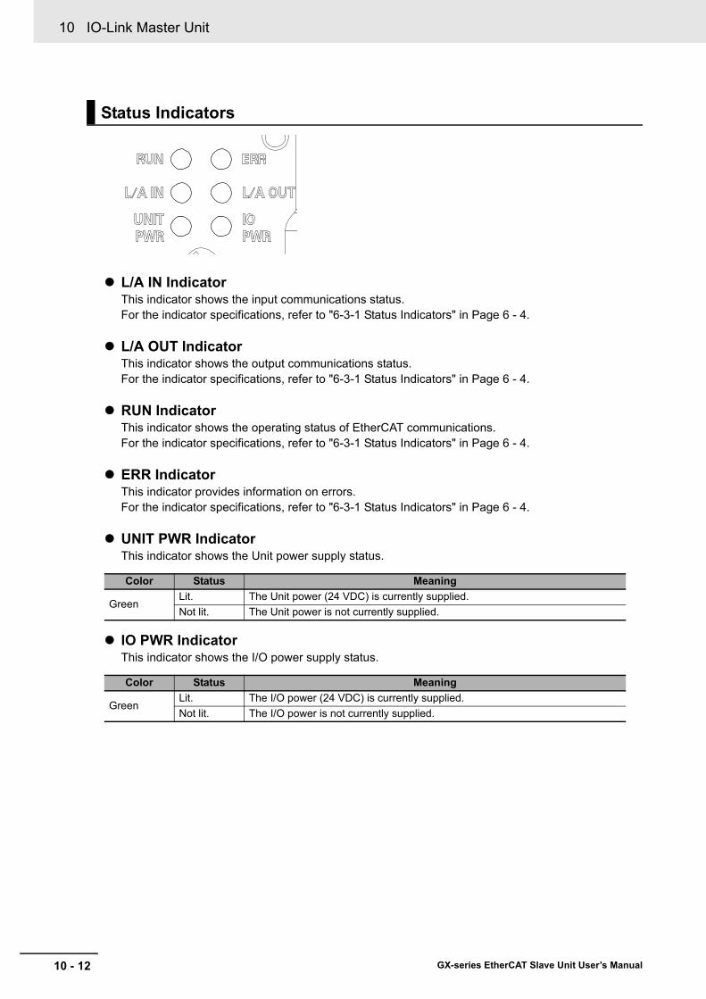
10 IO-Link Master Unit
10 - 12 GX-series EtherCAT Slave Unit User’s Manual
L/A IN IndicatorThis indicator shows the input communications status.For the indicator specifications, refer to "6-3-1 Status Indicators" in Page 6 - 4.
L/A OUT IndicatorThis indicator shows the output communications status.For the indicator specifications, refer to "6-3-1 Status Indicators" in Page 6 - 4.
RUN IndicatorThis indicator shows the operating status of EtherCAT communications.For the indicator specifications, refer to "6-3-1 Status Indicators" in Page 6 - 4.
ERR IndicatorThis indicator provides information on errors.For the indicator specifications, refer to "6-3-1 Status Indicators" in Page 6 - 4.
UNIT PWR IndicatorThis indicator shows the Unit power supply status.
IO PWR IndicatorThis indicator shows the I/O power supply status.
Status Indicators
Color Status Meaning
GreenLit. The Unit power (24 VDC) is currently supplied.Not lit. The Unit power is not currently supplied.
Color Status Meaning
GreenLit. The I/O power (24 VDC) is currently supplied.Not lit. The I/O power is not currently supplied.

10 - 13
10 IO-Link Master Unit
GX-series EtherCAT Slave Unit User’s Manual
10-4 Specifications
10
10-4-2 Part Nam
es and Functions
C/E IndicatorThese indicator show the IO-Link communications status and error status.
C/Q IndicatorThese indicator show the digital I/O status.
I/O Indicators
Label Color Status Meaning
A
Green
Lit.IO-Link communications are in progress during operation in IO-Link Mode.
Not lit.
• IO-Link communications are stopped during operation in IO-Link Mode.
• Operation is currently performed in SIO (DI) or SIO (DO) Mode.
• The port is disabled.
Red
Flashing (1-s intervals)
There is an IO-Link communications error during operation in IO-Link Mode.
Not lit.
• There are no IO-Link communications errors during operation in IO-Link Mode.
• Operation is currently performed in SIO (DI) or SIO (DO) Mode.
• The port is disabled.
Label Color Status Meaning
B Yellow
Lit.• The pin-2 input signal is ON during operation in IO-Link Mode.• The I/O signal is ON during operation in SIO (DI) Mode or SIO
(DO) Mode.
Not lit.
• The pin-2 input signal is OFF during operation in IO-Link Mode.
• The I/O signal is OFF during operation in SIO (DI) Mode or SIO (DO) Mode.
• The port is disabled.
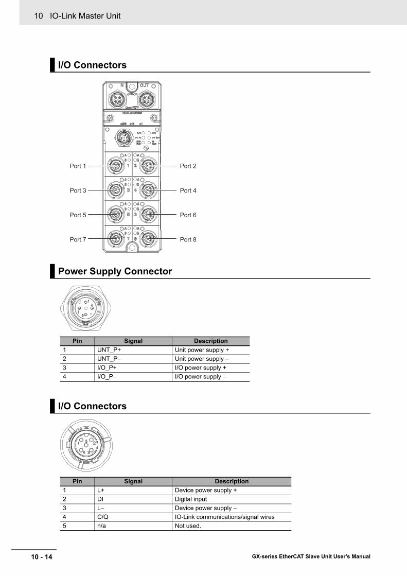
10 IO-Link Master Unit
10 - 14 GX-series EtherCAT Slave Unit User’s Manual
I/O Connectors
Power Supply Connector
Pin Signal Description1 UNT_P+ Unit power supply +2 UNT_P− Unit power supply −3 I/O_P+ I/O power supply +4 I/O_P− I/O power supply −
I/O Connectors
Pin Signal Description1 L+ Device power supply +2 DI Digital input3 L− Device power supply −4 C/Q IO-Link communications/signal wires5 n/a Not used.
Port 1
Port 3
Port 5
Port 7
Port 2
Port 4
Port 6
Port 8
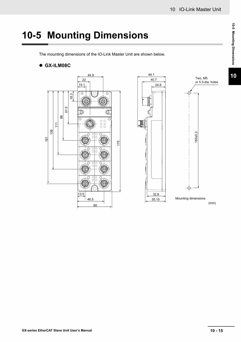
10 - 15
10 IO-Link Master Unit
GX-series EtherCAT Slave Unit User’s Manual
10-5 Mounting D
imensions
10
10-5 Mounting Dimensions
The mounting dimensions of the IO-Link Master Unit are shown below.
GX-ILM08C
(mm)
13.5
46.5
15.1
44.922
18.3
57.5
8611
113
616
1
60
175
40.749.1
24.8
32.835.15
Two, M5 or 5.3-dia. holes
Mounting dimensions16
5±0.
2
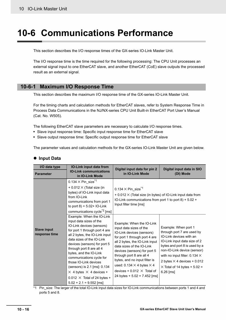
10 IO-Link Master Unit
10 - 16 GX-series EtherCAT Slave Unit User’s Manual
10-6 Communications Performance
This section describes the I/O response times of the GX-series IO-Link Master Unit.
The I/O response time is the time required for the following processing: The CPU Unit processes an external signal input to one EtherCAT slave, and another EtherCAT (CoE) slave outputs the processed result as an external signal.
This section describes the maximum I/O response time of the GX-series IO-Link Master Unit.
For the timing charts and calculation methods for EtherCAT slaves, refer to System Response Time in Process Data Communications in the NJ/NX-series CPU Unit Built-in EtherCAT Port User’s Manual (Cat. No. W505).
The following EtherCAT slave parameters are necessary to calculate I/O response times.• Slave input response time: Specific input response time for EtherCAT slave• Slave output response time: Specific output response time for EtherCAT slave
The parameter values and calculation methods for the GX-series IO-Link Master Unit are given below.
Input Data
*1 Pin_size: The larger of the total IO-Link input data sizes for IO-Link communications between ports 1 and 4 and ports 5 and 8.
10-6-1 Maximum I/O Response Time
I/O data type IO-Link input data from IO-Link communications
in IO-Link Mode
Digital input data for pin 2 in IO-Link Mode
Digital input data in SIO (DI) ModeParameter
Slave input response time
0.134 × Pin_size*1
+ 0.012 × (Total size (in bytes) of IO-Link input data from IO-Link communications from port 1 to port 8) + 5.02+ IO-Link communications cycle*2 [ms]
0.134 × Pin_size*1
+ 0.012 × (Total size (in bytes) of IO-Link input data from IO-Link communications from port 1 to port 8) + 5.02 + Input filter time [ms]
Example: When the IO-Link input data sizes of the IO-Link devices (sensors) for port 1 through port 4 are all 2 bytes, the IO-Link input data sizes of the IO-Link devices (sensors) for port 5 through port 8 are all 4 bytes, and the IO-Link communications cycle for those IO-Link devices (sensors) is 2.1 [ms]: 0.134 × 4 bytes × 4 devices +
0.012 × Total of 24 bytes + 5.02 + 2.1 = 9.552 [ms]
Example: When the IO-Link input data sizes of the IO-Link devices (sensors) for port 1 through port 4 are all 2 bytes, the IO-Link input data sizes of the IO-Link devices (sensors) for port 5 through port 8 are all 4 bytes, and no input filter is used: 0.134 × 4 bytes × 4
devices + 0.012 × Total of 24 bytes + 5.02 = 7.452 [ms]
Example: When port 1 through port 7 are used by IO-Link devices with an IO-Link input data size of 2 bytes and port 8 is used by a non-IO-Link device (sensor) with no input filter: 0.134 × 2 bytes × 4 devices + 0.012
× Total of 14 bytes + 5.02 = 6.26 [ms]

10 - 17
10 IO-Link Master Unit
GX-series EtherCAT Slave Unit User’s Manual
10-6 Com
munications
Performance
10
10-6-1 Maxim
um I/O
Response Tim
e
*2 For information on how to determine the IO-Link communications cycle, refer to "10-6-2 Determining the IO-Link Communications Cycle" in Page 10 - 18Determining the IO-Link Communications Cycle.
Output Data
*1 Pout_size: The larger of the total IO-Link output data sizes for IO-Link communications between ports 1 and 4 and ports 5 and 8.
*2 For information on how to determine the IO-Link communications cycle, refer to "10-6-2 Determining the IO-Link Communications Cycle" in Page 10 - 18.
I/O data type IO-Link output data from IO-Link communications in IO-Link Mode Digital output data in SIO (DO) Mode
Parameter
Slave output response time
0.091 × Pout_size*1 + 0.001 × (Total size (in bytes) of IO-Link output data from IO-Link communications from port 1 to port 8) + 3.04 + IO-Link communications cycle*2 [ms]
0.091 × Pout_size*1 + 0.001 × (Total size (in bytes) of IO-Link output data from IO-Link communications from port 1 to port 8) + 3.04 [ms]
Example: When the IO-Link output data sizes of the IO-Link devices (actuators) for port 1 through port 4 are all 2 bytes, the IO-Link output data sizes of the IO-Link devices (actuators) for port 5 through port 8 are all 4 bytes, and the IO-Link communications cycle for those IO-Link devices (actuators) is 2.1 [ms]: 0.091 × 4
bytes × 4 devices + 0.001 × Total of 24 bytes + 3.04 + 2.1 = 6.62 [ms]
Example: When port 1 through port 7 are used by IO-Link devices with an IO-Link output data size of 2 bytes and port 8 is used by a non-IO-Link device (actuator): 0.091 × 2 bytes × 4 devices + 0.001 × Total of 14 bytes + 3.04 = 3.782 [ms]

10 IO-Link Master Unit
10 - 18 GX-series EtherCAT Slave Unit User’s Manual
The IO-Link communications cycle depends on the baud rate of the IO-Link devices, as described below.Refer to the instruction manuals for individual IO-Link devices for the IO-Link device baud rates.
The IO-Link communications cycle depends on whether the minimum cycle time of the IO-Link devices is less than or equal to 1.1 ms or greater than 1.1 ms, as described below.• When the minimum cycle time of the IO-Link devices is less than or equal to 1.1 ms
IO-Link communications cycle is 2.1 [ms] and does not change.• When the minimum cycle time of the IO-Link devices is greater than 1.1 ms
The IO-Link communications cycle = (Minimum cycle time of the IO-Link devices*) +1.0 [ms]
The IO-Link communications cycle will be as described below.The IO-Link communications cycle = (Minimum cycle time of the IO-Link devices*) [ms]* You can check the minimum cycle times for the IO-Link devices in the instruction manuals for the IO-Link
devices.Or, you can place the CX-ConfiguratorFDT online and check the cycle time in Read Device Configuration in the Diagnosis Tab Page for the IO-Link Master Unit, as shown in the following screen capture.
10-6-2 Determining the IO-Link Communications Cycle
When the IO-Link Device Baud Rate Is COM3 (230.4 kbps)
When the IO-Link Device Baud Rate IO-Link Device Is COM2 (38.4 kbps) or COM1 (4.8 kbps)

10 - 19
10 IO-Link Master Unit
GX-series EtherCAT Slave Unit User’s Manual
10-7 Connected D
eviceSpecifications and M
odels
10
10-7 Connected Device Specifications and Models
Cables to Connect a GX-type IO-Link Master Unit to a Master or Slave with an RJ45 Connector
Connects two GX-type IO-Link Master Units
EtherCAT Cables
Name and appearance Specifica-tion
Num-ber of cable con-
ductors
Avail-able
connec-tors
Cable connec-
tion direc-tion
Cable length Model
XS5W Industrial Ethernet Con-nectors with Reinforced-shield Cable (Cable with Connectors on Both Ends (M12 Straight/RJ45))
M12 plug (D-cod-ing, male) to RJ45
4 Smart-click connec-tor
Straight/straight
0.5 m XS5W-T421-BMC-SS
1 m XS5W-T421-CMC-SS
2 m XS5W-T421-DMC-SS
3 m XS5W-T421-EMC-SS
5 m XS5W-T421-GMC-SS
10 m XS5W-T421-JMC-SS
Name and appearance Specifica-tion
Num-ber of cable con-
ductors
Avail-able
connec-tors
Cable connec-
tion direc-tion
Cable length Model
XS5W Industrial Ethernet Con-nectors with Reinforced-shield Cable (Cable with Connectors on Both Ends (M12 Straight/M12 Straight))
M12 plug (D-coding, male) to M12 plug (D-coding, male)
4 Smart-click connec-tor
Straight/straight
0.5 m XS5W-T421-BM2-SS
1 m XS5W-T421-CM2-SS
2 m XS5W-T421-DM2-SS
3 m XS5W-T421-EM2-SS
5 m XS5W-T421-GM2-SS
10 m XS5W-T421-JM2-SS

10 IO-Link Master Unit
10 - 20 GX-series EtherCAT Slave Unit User’s Manual
Cables to Convert Connections from Sensors with M8 Plugs
Power Supply Cables for GX-type IO-Link Master Units
Name and appearance Specifica-tion
Number of cable conduc-
tors
Avail-able
connec-tors
Cable connec-
tion direction
Cable length Model
XS5F Connector with Cable, Socket on One End
M12 socket on one end (A-coding, female), for DC
4 Smart-click connec-tor
Straight 1 m XS5F-D421-C80-F2 m XS5F-D421-D80-F3 m XS5F-D421-E80-F5 m XS5F-D421-G80-F10 m XS5F-D421-J80-F
XS5W Connector with Cable (Socket on One End, Plug on Other End)
M12 socket (A-coding, female) to M12 plug (A-coding, male), uses DC
4 Smart-click connec-tor
Straight/straight
1 m XS5W-D421-C81-F
2 m XS5W-D421-D81-F
3 m XS5W-D421-E81-F
5 m XS5W-D421-G81-F
10 m XS5W-D421-J81-F
I/O Cables for GX-type IO-Link Master Units
Name and appearance Specifica-tion
Num-ber of cable con-
ductors
Available connec-
tors
Cable connec-
tion direction
Cable length Model
XS3W Connector with Cable (M8 Socket/M12 Plug)
M8 socket (A-coding, female) to M12 plug (A-coding, male), uses DC
4 M8 screw connec-tor/M12 Smartclick connector
Straight 0.2 m XS3W-M42C-4C2-A

10 - 21
10 IO-Link Master Unit
GX-series EtherCAT Slave Unit User’s Manual
10-7 Connected D
eviceSpecifications and M
odels
10
Extension Cables from Sensors with M12 Plugs
Use cables with a connector on one end to connect sensors. Refer to the catalog for the sensor for recommended products.
This connector is used when branching a GX-type Unit power supply.
This is a waterproof cover for unused M12 GX connectors (female).When you use this waterproof cover, you can maintain the IP67 protective structure.The following two types of covers are available. Either one can be mounted on an EtherCAT communications connector or I/O connector.
Name and appearance Specifica-tion
Num-ber of cable con-
ductors
Avail-able
connec-tors
Cable con-nection
direction
Cable length Model
XS5W Connector with Cable (Socket on One End, Plug on Other End)
M12 socket (A-coding, female) to M12 plug (A-coding, male), uses DC
4 Smart-click connec-tor
Straight/straight
1 m XS5W-D421-C81-F
2 m XS5W-D421-D81-F
3 m XS5W-D421-E81-F
5 m XS5W-D421-G81-F
10 m XS5W-D421-J81-F
I/O Cables for NX-type IO-Link Master Units
Power Supply T-Joint Connector
Name and appearance Specification Connector type ModelXS5R Plug/Socket T-Joint Con-nector
M12 Smartclick connector
XS5R-D427-5
Waterproof Cover for Connectors
Name and appearance Specification Connector type Materials ModelM12 Threaded Waterproof Cover*1
M12Screw-type con-nector
Brass/nickel plated
XS2Z-22
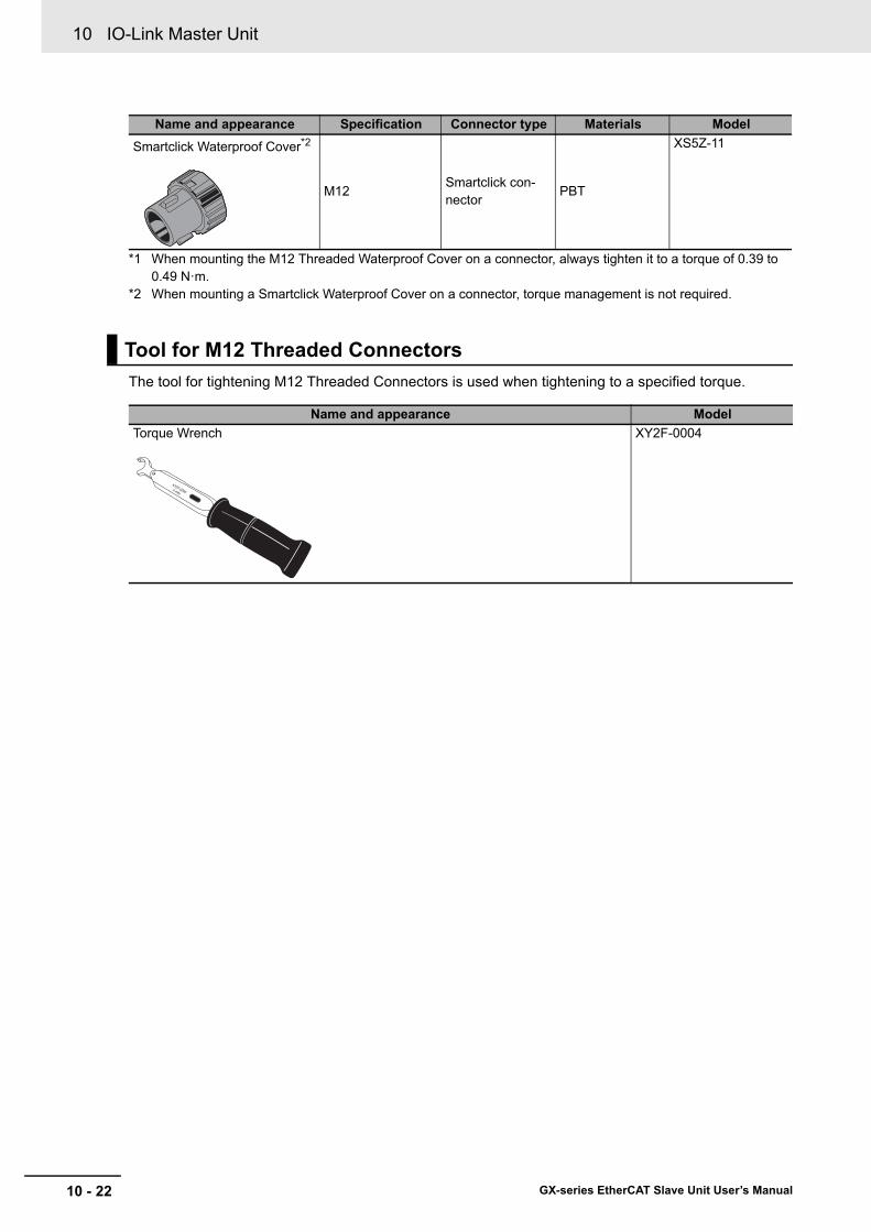
10 IO-Link Master Unit
10 - 22 GX-series EtherCAT Slave Unit User’s Manual
*1 When mounting the M12 Threaded Waterproof Cover on a connector, always tighten it to a torque of 0.39 to 0.49 N·m.
*2 When mounting a Smartclick Waterproof Cover on a connector, torque management is not required.
The tool for tightening M12 Threaded Connectors is used when tightening to a specified torque.
Smartclick Waterproof Cover*2
M12Smartclick con-nector
PBT
XS5Z-11
Tool for M12 Threaded Connectors
Name and appearance ModelTorque Wrench XY2F-0004
Name and appearance Specification Connector type Materials Model
11 - 1
11
GX-series EtherCAT Slave Unit User’s Manual
This chapter overviews the Expansion Unit.
11-1 Overview of the Expansion Unit . . . . . . . . . . . . . . . . . . . . . . . . . . . . . . . . . 11-211-1-1 Connecting Expansion Units . . . . . . . . . . . . . . . . . . . . . . . . . . . . . . . . . . . . . . .11-211-1-2 I/O Power Supply . . . . . . . . . . . . . . . . . . . . . . . . . . . . . . . . . . . . . . . . . . . . . . .11-3
11-2 Specifications of Expansion Unit . . . . . . . . . . . . . . . . . . . . . . . . . . . . . . . . 11-411-2-1 8-point Input Expansion Unit XWT-ID08/ID08-1 . . . . . . . . . . . . . . . . . . . . . . . .11-511-2-2 8-point Output Expansion Unit XWT-OD08/OD08-1 . . . . . . . . . . . . . . . . . . . . .11-811-2-3 16-point Input Expansion Unit XWT-ID16/ID16-1 . . . . . . . . . . . . . . . . . . . . . .11-1111-2-4 16-point Output Expansion Unit XWT-OD16/OD16-1 . . . . . . . . . . . . . . . . . . .11-14
11-3 Mounting Dimensions . . . . . . . . . . . . . . . . . . . . . . . . . . . . . . . . . . . . . . . . 11-17
Expansion Unit
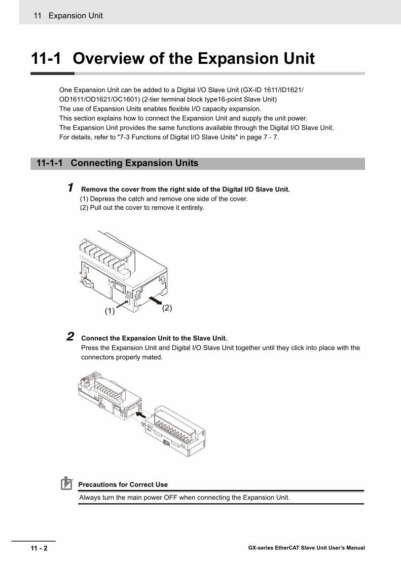
11 Expansion Unit
11 - 2 GX-series EtherCAT Slave Unit User’s Manual
11-1 Overview of the Expansion Unit
One Expansion Unit can be added to a Digital I/O Slave Unit (GX-ID 1611/ID1621/ OD1611/OD1621/OC1601) (2-tier terminal block type16-point Slave Unit)The use of Expansion Units enables flexible I/O capacity expansion.This section explains how to connect the Expansion Unit and supply the unit power.The Expansion Unit provides the same functions available through the Digital I/O Slave Unit.For details, refer to "7-3 Functions of Digital I/O Slave Units" in page 7 - 7.
1 Remove the cover from the right side of the Digital I/O Slave Unit. (1) Depress the catch and remove one side of the cover. (2) Pull out the cover to remove it entirely.
2 Connect the Expansion Unit to the Slave Unit. Press the Expansion Unit and Digital I/O Slave Unit together until they click into place with the connectors properly mated.
Precautions for Correct Use
Always turn the main power OFF when connecting the Expansion Unit.
11-1-1 Connecting Expansion Units
(1) (2)

11 - 3
11 Expansion Unit
GX-series EtherCAT Slave Unit User’s Manual
11-1 Overview
of the Expansion Unit
11
11-1-2 I/O P
ower S
upply
The I/O power supply method when an Expansion Unit is connected differs in cases. In some cases I/O power can be supplied only to Slave Unit. In the other cases, it must be supplied to both the Slave Unit and the Expansion Unit.These differences depend on the I/O combination. Refer to the following table for the correct supply.
11-1-2 I/O Power Supply
Expansion Unit
Slave Unit
Input Output
XWT-ID08(-1) XWT-ID16(-1) XWT-OD08(-1) XWT-OD16(-1)
InputGX-ID1611 Power is supplied only to the Slave Unit.
Power supply to the Expansion Unit is not required.
Power is supplied to both the Slave Unit and Expansion Unit.GX-ID1621
OutputGX-OD1611
Power is supplied to both the Slave Unit and Expansion Unit.
Power is supplied to both the Slave Unit and Expansion Unit.
GX-OD1621GX-OC1601

11 Expansion Unit
11 - 4 GX-series EtherCAT Slave Unit User’s Manual
11-2 Specifications of Expansion Unit
The chart below shows the Expansion Unit specifications, component names and functions, internal circuits and wiring diagram.Refer to the following corresponding page to each model.
Model
Reference page
Specification Names and functions
Internal circuits diagram
Wiring diagram
XWT-ID08XWT-ID08-1
11-5 11-5 11-6 11-7
XWT-OD08XWT-OD08-1
11-8 11-8 11-9 11-10
XWT-ID16XWT-ID16-1
11-11 11-11 11-12 11-13
XWT-OD16XWT-OD16-1
11-14 11-14 11-15 11-16
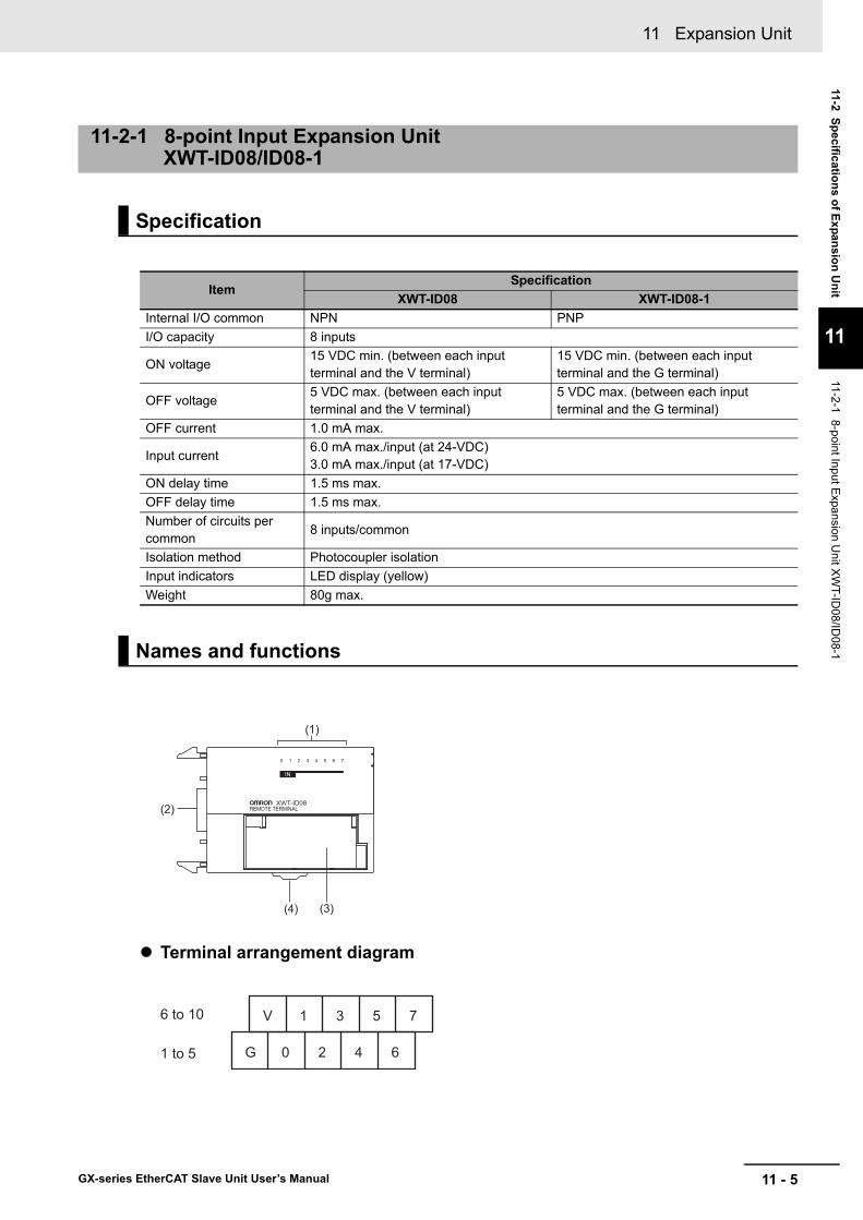
11 - 5
11 Expansion Unit
GX-series EtherCAT Slave Unit User’s Manual
11-2 Specifications of Expansion Unit
11
11-2-1 8-point Input Expansion Unit X
WT-ID
08/ID08-1
Terminal arrangement diagram
11-2-1 8-point Input Expansion Unit XWT-ID08/ID08-1
Specification
ItemSpecification
XWT-ID08 XWT-ID08-1Internal I/O common NPN PNPI/O capacity 8 inputs
ON voltage15 VDC min. (between each input terminal and the V terminal)
15 VDC min. (between each input terminal and the G terminal)
OFF voltage5 VDC max. (between each input terminal and the V terminal)
5 VDC max. (between each input terminal and the G terminal)
OFF current 1.0 mA max.
Input current6.0 mA max./input (at 24-VDC)3.0 mA max./input (at 17-VDC)
ON delay time 1.5 ms max.OFF delay time 1.5 ms max.Number of circuits per common
8 inputs/common
Isolation method Photocoupler isolationInput indicators LED display (yellow)Weight 80g max.
Names and functions
IN
(1)
(2)
(3)(4)
6 to 10
1 to 5
V 1 3 5 7
G 0 2 4 6
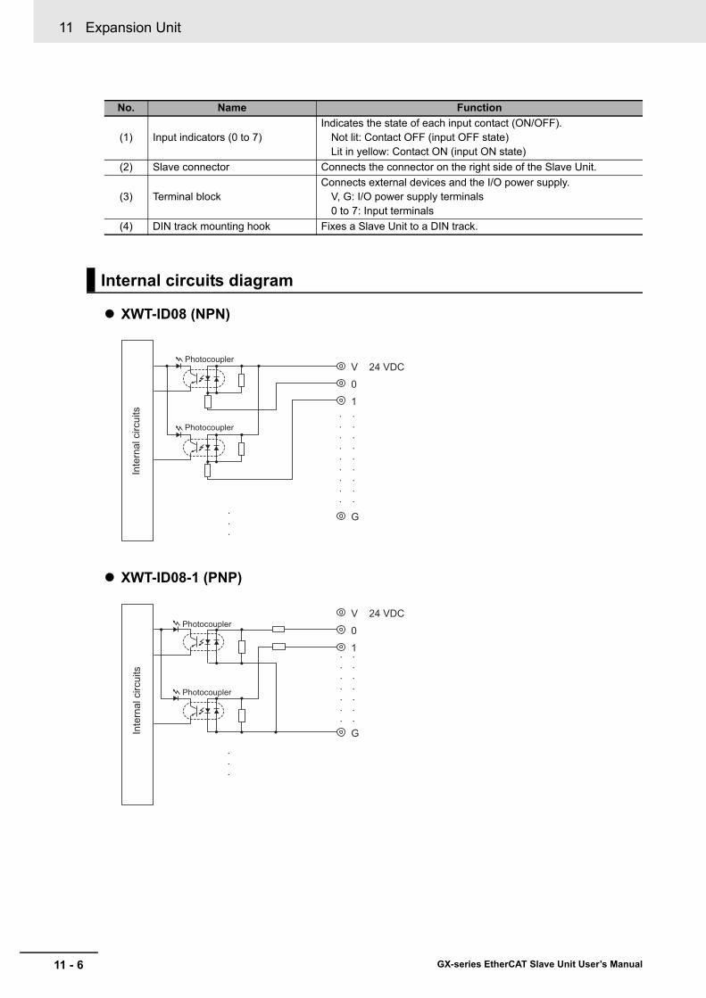
11 Expansion Unit
11 - 6 GX-series EtherCAT Slave Unit User’s Manual
XWT-ID08 (NPN)
XWT-ID08-1 (PNP)
No. Name Function
(1) Input indicators (0 to 7)Indicates the state of each input contact (ON/OFF).
Not lit: Contact OFF (input OFF state)Lit in yellow: Contact ON (input ON state)
(2) Slave connector Connects the connector on the right side of the Slave Unit.
(3) Terminal blockConnects external devices and the I/O power supply.
V, G: I/O power supply terminals0 to 7: Input terminals
(4) DIN track mounting hook Fixes a Slave Unit to a DIN track.
Internal circuits diagram
V 24 VDC
0
1
G
Photocoupler
Photocoupler
Inte
rnal
circ
uits •
•
•
•
•
•
•
•
•
•
•
•
•
•
•
•
•
•
•
•
•
V 24 VDC
0
1
G
Photocoupler
Photocoupler
•
•
•
•
•
•
•
•
•
•
•
•
•
•
Inte
rnal
circ
uits
•
•
•

11 - 7
11 Expansion Unit
GX-series EtherCAT Slave Unit User’s Manual
11-2 Specifications of Expansion Unit
11
11-2-1 8-point Input Expansion Unit X
WT-ID
08/ID08-1
XWT-ID08 (NPN)
XWT-ID08-1 (PNP)
Reference
Wire colors have been changed according to revisions in the JIS standards for photoelectric and proximity sensors.The colors in parentheses are the wire colors prior to the revisions.
Wiring diagram
NPN output 3-wire sensor
(Photoelectric sensor, proximity sensor)
2-wire sensor(Limit switch, etc.)
Blu
e (b
lack
)
Blac
k (w
hite
)
Brow
n (w
hite
)
Blu
e (b
lack
)
Bro
wn
(red
)
I/O power supply(24 VDC)
V 1 3 5 7
G 0 2 4 6
I/O power supply
PNP output 3-wire sensor
(Photoelectric sensor, proximity sensor)
2-wire sensor(Limit switch, etc.)
Blu
e (b
lack
)
Bla
ck (w
hite
)
Brow
n (w
hite
)
Blu
e (b
lack
)
Bro
wn
(red
)
V 1 3 5 7
G 0 2 4 6
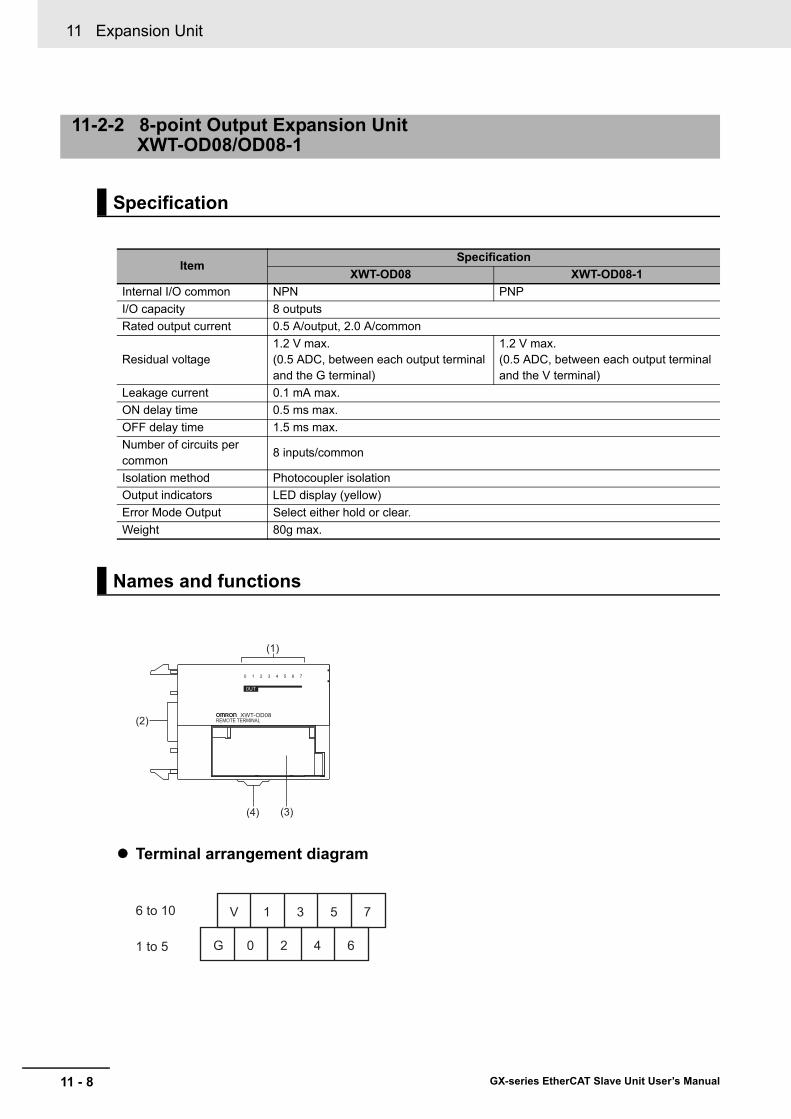
11 Expansion Unit
11 - 8 GX-series EtherCAT Slave Unit User’s Manual
Terminal arrangement diagram
11-2-2 8-point Output Expansion Unit XWT-OD08/OD08-1
Specification
ItemSpecification
XWT-OD08 XWT-OD08-1Internal I/O common NPN PNPI/O capacity 8 outputsRated output current 0.5 A/output, 2.0 A/common
Residual voltage1.2 V max.(0.5 ADC, between each output terminal and the G terminal)
1.2 V max.(0.5 ADC, between each output terminal and the V terminal)
Leakage current 0.1 mA max.ON delay time 0.5 ms max.OFF delay time 1.5 ms max.Number of circuits per common
8 inputs/common
Isolation method Photocoupler isolationOutput indicators LED display (yellow)Error Mode Output Select either hold or clear.Weight 80g max.
Names and functions
(1)
(2)
(3)(4)
0UT
6 to 10
1 to 5
V 1 3 5 7
G 0 2 4 6

11 - 9
11 Expansion Unit
GX-series EtherCAT Slave Unit User’s Manual
11-2 Specifications of Expansion Unit
11
11-2-2 8-point Output E
xpansion Unit X
WT-O
D08/O
D08-1
XWT-OD08 (NPN)
XWT-OD08-1 (PNP)
No. Name Function
(1) Output indicators (0 to 7)Indicates the state of each output contact (ON/OFF).
Not lit: Contact OFF (output OFF state)Lit in yellow: Contact ON (output ON state)
(2) Slave connector Connects the connector on the right side of the Slave Unit.
(3) Terminal blockConnects external devices and the I/O power supply.
V, G: I/O power supply terminals0 to 7: Output terminals
(4) DIN track mounting hook Fixes a Slave Unit to a DIN track.
Internal circuits diagram
0
1
G
V 24 VDCPhotocoupler
Photocoupler
Volta
ge d
rop
•
•
•
•
•
•
•
•
•
•
•
•
•
•
•
•
•
•
•
•
•
•
Inte
rnal
circ
uits
•
•
•
0
1
G
V 24 VDCPhotocoupler
Photocoupler
Volta
ge d
rop
•
•
•
•
•
•
•
•
•
•
•
•
•
•
•
•
Inte
rnal
circ
uits
•
•
•

11 Expansion Unit
11 - 10 GX-series EtherCAT Slave Unit User’s Manual
XWT-OD08 (NPN)
XWT-OD08-1 (PNP)
Precautions for Correct Use
When using an inductive load, such as a solenoid valve, either use a built-in diode for absorbing the counterelectromotive force or install an external diode. (Refer to "A-4 Wiring External Output Signal Lines" in page A - 71.)
Wiring diagram
I/O power supply(24 VDC)
Solenoid valve, etc. Solenoid valve, etc.
V 1 3 5 7
G 0 2 4 6
I/O power supply(24 VDC)
Solenoid valve, etc. Solenoid valve, etc.
V 1 3 5 7
G 0 2 4 6
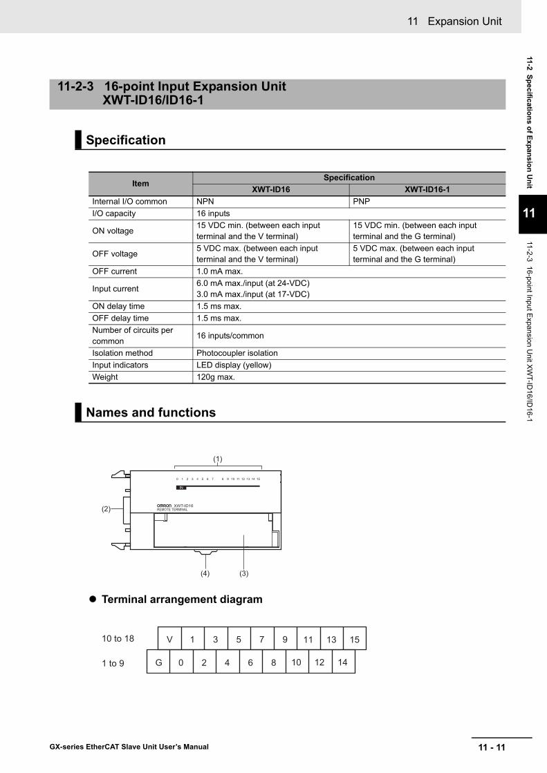
11 - 11
11 Expansion Unit
GX-series EtherCAT Slave Unit User’s Manual
11-2 Specifications of Expansion Unit
11
11-2-3 16-point Input Expansion U
nit XW
T-ID16/ID
16-1
Terminal arrangement diagram
11-2-3 16-point Input Expansion Unit XWT-ID16/ID16-1
Specification
ItemSpecification
XWT-ID16 XWT-ID16-1Internal I/O common NPN PNPI/O capacity 16 inputs
ON voltage15 VDC min. (between each input terminal and the V terminal)
15 VDC min. (between each input terminal and the G terminal)
OFF voltage5 VDC max. (between each input terminal and the V terminal)
5 VDC max. (between each input terminal and the G terminal)
OFF current 1.0 mA max.
Input current6.0 mA max./input (at 24-VDC)3.0 mA max./input (at 17-VDC)
ON delay time 1.5 ms max.OFF delay time 1.5 ms max.Number of circuits per common
16 inputs/common
Isolation method Photocoupler isolationInput indicators LED display (yellow)Weight 120g max.
Names and functions
IN
(1)
(2)
(3)(4)
10 to 18
1 to 9
V 1 3 5 7 9
G 0 2 4 6 8 10 12 14
11 13 15
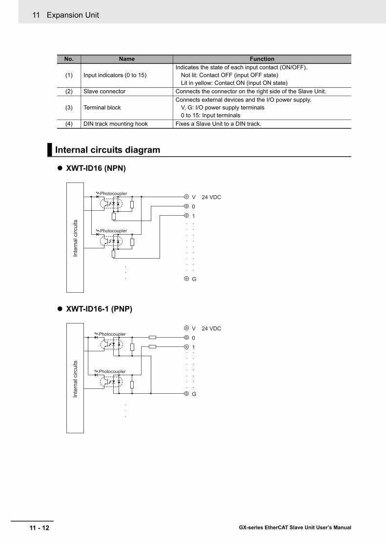
11 Expansion Unit
11 - 12 GX-series EtherCAT Slave Unit User’s Manual
XWT-ID16 (NPN)
XWT-ID16-1 (PNP)
No. Name Function
(1) Input indicators (0 to 15)Indicates the state of each input contact (ON/OFF).
Not lit: Contact OFF (input OFF state)Lit in yellow: Contact ON (input ON state)
(2) Slave connector Connects the connector on the right side of the Slave Unit.
(3) Terminal blockConnects external devices and the I/O power supply.
V, G: I/O power supply terminals0 to 15: Input terminals
(4) DIN track mounting hook Fixes a Slave Unit to a DIN track.
Internal circuits diagram
V 24 VDC
0
1
G
Photocoupler
Photocoupler
•
•
•
•
•
•
•
•
•
•
•
•
•
•
•
•
•
•
Inte
rnal
circ
uits
•
•
•
V 24 VDC
0
1
G
Photocoupler
Photocoupler
•
•
•
•
•
•
•
•
•
•
•
•
•
•
Inte
rnal
circ
uits
•
•
•

11 - 13
11 Expansion Unit
GX-series EtherCAT Slave Unit User’s Manual
11-2 Specifications of Expansion Unit
11
11-2-3 16-point Input Expansion U
nit XW
T-ID16/ID
16-1
XWT-ID16 (NPN)
XWT-ID16-1 (PNP)
Reference
Wire colors have been changed according to revisions in the JIS standards for photoelectric and proximity sensors.The colors in parentheses are the wire colors prior to the revisions.
Wiring diagram
NPN output 3-wire sensor(Photoelectric sensor,
proximity sensor)
2-wire sensor(Limit switch, etc.)
Blu
e (b
lack
)
Blac
k (w
hite
)
Brow
n (w
hite
)
Blu
e (b
lack
)
Bro
wn
(red
)
V 1 3 5 7 9 11 13 15
G 0 2 4 6 8 10 12 14
I/O power supply(24 VDC)
V 1 3 5 7 9 11 13 15
G 0 2 4 6 8 10 12 14
I/O power supply(24 VDC)
PNP output 3-wire sensor
(Photoelectric sensor, proximity sensor)
2-wire sensor(Limit switch, etc.)
Bro
wn
(red
)
Blac
k (w
hite
)
Blu
e (b
lack
)
Brow
n (w
hite
)
Blu
e (b
lack
)
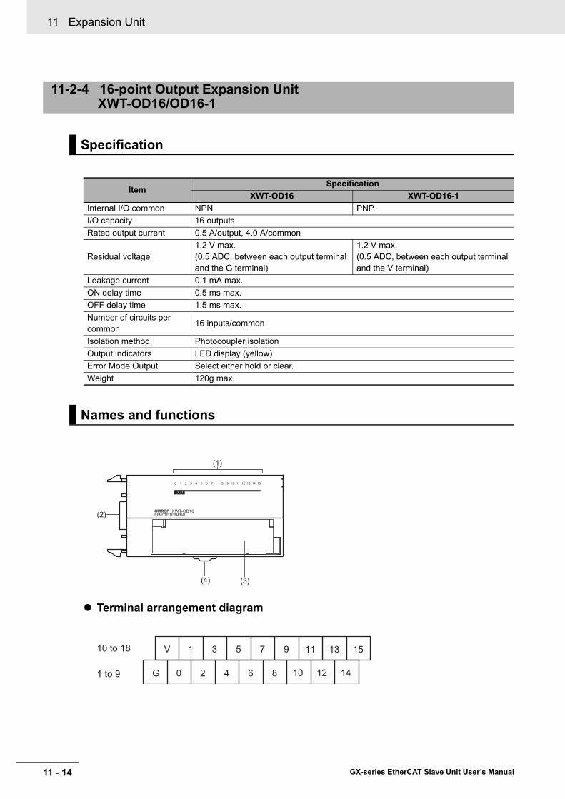
11 Expansion Unit
11 - 14 GX-series EtherCAT Slave Unit User’s Manual
Terminal arrangement diagram
11-2-4 16-point Output Expansion Unit XWT-OD16/OD16-1
Specification
ItemSpecification
XWT-OD16 XWT-OD16-1Internal I/O common NPN PNPI/O capacity 16 outputsRated output current 0.5 A/output, 4.0 A/common
Residual voltage1.2 V max.(0.5 ADC, between each output terminal and the G terminal)
1.2 V max.(0.5 ADC, between each output terminal and the V terminal)
Leakage current 0.1 mA max.ON delay time 0.5 ms max.OFF delay time 1.5 ms max.Number of circuits per common
16 inputs/common
Isolation method Photocoupler isolationOutput indicators LED display (yellow)Error Mode Output Select either hold or clear.Weight 120g max.
Names and functions
OUT
(1)
(2)
(3)(4)
10 to 18
1 to 9
V 1 3 5 7 9
G 0 2 4 6 8 10 12 14
11 13 15

11 - 15
11 Expansion Unit
GX-series EtherCAT Slave Unit User’s Manual
11-2 Specifications of Expansion Unit
11
11-2-4 16-point Output E
xpansion Unit X
WT-O
D16/O
D16-1
XWT-OD16 (NPN)
XWT-OD16-1 (PNP)
No. Name Function
(1) Output indicators (0 to 15)Indicates the state of each output contact (ON/OFF).
Not lit: Contact OFF (output OFF state)Lit in yellow: Contact ON (output ON state)
(2) Slave connector Connects the connector on the right side of the Slave Unit.
(3) Terminal blockConnects external devices and the I/O power supply.
V, G: I/O power supply terminals0 to 15: Output terminals
(4) DIN track mounting hook Fixes a Slave Unit to a DIN track.
Internal circuits diagram
0
1
G
V 24 VDCPhotocoupler
Photocoupler
Volta
ge d
rop
•
•
•
•
•
•
•
•
•
•
•
•
•
•
•
•
•
•
•
•
•
•
Inte
rnal
circ
uits
•
•
•
0
1
G
V 24 VDCPhotocoupler
Photocoupler
Volta
ge d
rop
•
•
•
•
•
•
•
•
•
•
•
•
•
•
•
•
•
•
Inte
rnal
circ
uits
•
•
•
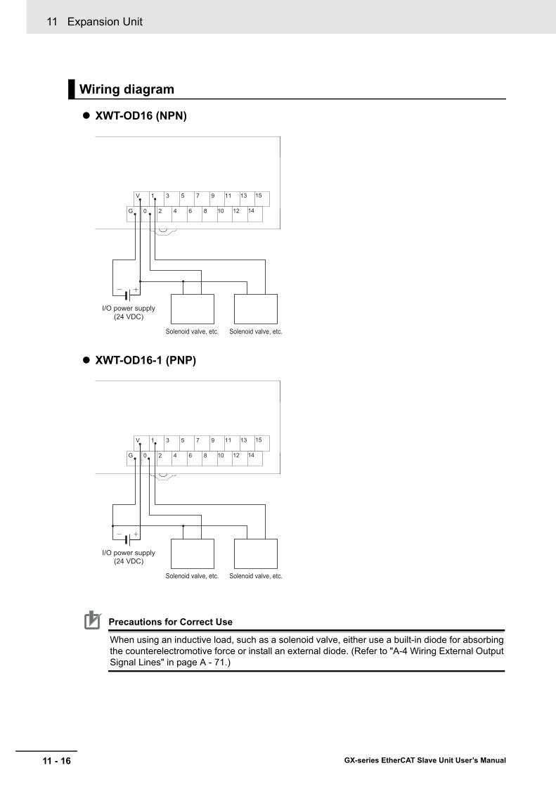
11 Expansion Unit
11 - 16 GX-series EtherCAT Slave Unit User’s Manual
XWT-OD16 (NPN)
XWT-OD16-1 (PNP)
Precautions for Correct Use
When using an inductive load, such as a solenoid valve, either use a built-in diode for absorbing the counterelectromotive force or install an external diode. (Refer to "A-4 Wiring External Output Signal Lines" in page A - 71.)
Wiring diagram
I/O power supply(24 VDC)
Solenoid valve, etc. Solenoid valve, etc.
V 1 3 5 7 9 11 13 15
G 0 2 4 6 8 10 12 14
I/O power supply(24 VDC)
Solenoid valve, etc. Solenoid valve, etc.
V 1 3 5 7 9 11 13 15
G 0 2 4 6 8 10 12 14

11 - 17
11 Expansion Unit
GX-series EtherCAT Slave Unit User’s Manual
11-3 Mounting D
imensions
11
11-3 Mounting Dimensions
The mounting dimensions of the Expansion Unit are shown below.
XWT-ID08/ID08-1/OD08/OD08-1
XWT-ID16/ID16-1/OD16/OD16-1
3.1
50
13 66 43.9
49.7
29.9
(mm)
0 1 2 3 4 5 6 70 1 2 3 4 5 6 7 8 9 10 11 12 13 14 158 9 10 11 12 13 14 15
3.1
50
12 94 43.9
49.7
29.9
(mm)

11 Expansion Unit
11 - 18 GX-series EtherCAT Slave Unit User’s Manual

12 - 1
12
GX-series EtherCAT Slave Unit User’s Manual
This chapter explains actions to be taken at errors, troubleshooting, and equipment maintenance.
12-1 Troubleshooting . . . . . . . . . . . . . . . . . . . . . . . . . . . . . . . . . . . . . . . . . . . . . . 12-212-1-1 Errors that Can be Checked with Status Indicator and Actions to Take . . . . . 12-212-1-2 Errors Unique to Each Slave Unit . . . . . . . . . . . . . . . . . . . . . . . . . . . . . . . . . . 12-712-1-3 Error Notification Methods and Types . . . . . . . . . . . . . . . . . . . . . . . . . . . . . . 12-1312-1-4 Sysmac Error Status Codes . . . . . . . . . . . . . . . . . . . . . . . . . . . . . . . . . . . . . 12-1412-1-5 Emergency Error Code . . . . . . . . . . . . . . . . . . . . . . . . . . . . . . . . . . . . . . . . . 12-1912-1-6 Application Layer Status Codes . . . . . . . . . . . . . . . . . . . . . . . . . . . . . . . . . . 12-21
12-2 Equipment Maintenance . . . . . . . . . . . . . . . . . . . . . . . . . . . . . . . . . . . . . . 12-2312-2-1 Cleaning . . . . . . . . . . . . . . . . . . . . . . . . . . . . . . . . . . . . . . . . . . . . . . . . . . . . 12-2312-2-2 Inspections . . . . . . . . . . . . . . . . . . . . . . . . . . . . . . . . . . . . . . . . . . . . . . . . . . 12-2312-2-3 Handling when Replacing Units . . . . . . . . . . . . . . . . . . . . . . . . . . . . . . . . . . 12-24
Troubleshooting and Maintenance

12 Troubleshooting and Maintenance
12 - 2 GX-series EtherCAT Slave Unit User’s Manual
12-1 Troubleshooting
Errors can be notified by status indicators on Slave Units.
In this section, the states of status indicator are indicated using the following abbreviations.
For details on definition of each state, refer to "6-3-1 Status Indicators" in page 6 - 4.
Errors of Slave Unit
12-1-1 Errors that Can be Checked with Status Indicator and Actions to Take
Abbreviation DefinitionOn ONOff OFFF Flickering (ON (50 ms) - OFF (50 ms) flashing)B Blinking (ON (200 ms) - OFF (200 ms) flashing)SF Single flash (ON (200 ms) - OFF (1000 ms) flashing)DF Double flash (ON (200 ms) - OFF (200 ms) - ON (200 ms) - OFF (1000 ms) flashing)− Unknown
[PWR] indicator
[L/A IN][L/A OUT]
LED
[RUN] indicator
[ERR] indicator Description Cause Actions
On F On OffEtherCATcommunication is in progress.
EtherCATcommunication is being executed.
PDO communications or both PDO and SDO communications are being executed.State is normal.
Off Off Off OffPower supply error
The power is not properly supplied to the Slave Unit.
After removing the following factors of power supply shutdown, restart the Slave Unit according to the specification of connected EtherCAT Master Unit.• Are the power supply
cables wired correctly?
• Are the power supply cables disconnected?
• Is the power supply voltage within the specification range?
• Is the power supply capacity sufficient?
• Is the power supply malfunctioning?

12 - 3
12 Troubleshooting and Maintenance
GX-series EtherCAT Slave Unit User’s Manual
12-1 Troubleshooting
12
12-1-1 Errors that C
an be Checked w
ith Status Indicator and Actions to Take
On − Off
On
Hardware error
A hardware failure occurred.
If the error does not clear even after the power is turned ON again, the Slave Unit hardware is damaged.Replace the Slave Unit.
F
BThe Expansion Unit is disconnected.
Check the Expansion Unit connection.
On − − B
Illegal switch setting
A range setting switch or other switch setting is illegal.
Check the switch settings then restart the Slave Unit according to the specification of connected EtherCAT Master Unit.
Non-volatile memory data error
A non-volatile memory data error occurred.
Use the Configuration Tool or SDO communications to restore the default data and restart the Slave Unit according to the specification of connected EtherCAT Master Unit.
Sync manager setting error
The sync manager setting is illegal.
Change to the correct settings.
Hardware errorA hardware failure occurred.
If the problem is not resolved even after the measures described above are taken, the Slave Unit hardware may be damaged. Replace the applicable Slave Unit.
[PWR] indicator
[L/A IN][L/A OUT]
LED
[RUN] indicator
[ERR] indicator Description Cause Actions

12 Troubleshooting and Maintenance
12 - 4 GX-series EtherCAT Slave Unit User’s Manual
Errors of EtherCAT Network
[PWR] indicator
[L/A IN][L/A OUT]
LED
[RUN] indicator
[ERR] indicator Description Cause Actions
On On − −Link established in physical layer
Operation standby status after establishing link in physical layer.
−
On Off − −Link not established in physical layer
A link in physical layer has not been established.
After checking the following items, restart the Slave Unit according to the specification of connected EtherCAT Master Unit.• Is the
communications cable wired correctly?
• Are any cables disconnected or loose in the part that connects to the connector?
• Is the cable length appropriate?
• Is the communications cable of the recommended specification?
The host master has not been started.
Check that EtherCAT Master Unit is operating correctly. If using an OMRON EtherCAT Master Unit, check the EtherCAT Master Unit mode and Slave Unit node addresses. If using EtherCAT Master Unit from another manufacturer, refer to the user's manual for that Master Unit.
A hardware failure occurred.
If the problem is not resolved even after the measures described above are taken, the Slave Unit hardware may be damaged. Replace the applicable Slave Unit.

12 - 5
12 Troubleshooting and Maintenance
GX-series EtherCAT Slave Unit User’s Manual
12-1 Troubleshooting
12
12-1-1 Errors that C
an be Checked w
ith Status Indicator and Actions to Take
On − − DF
Process data communica-tions timeout *
A communications error occurred.
After checking the following items, restart the Slave Unit according to the specification of connected EtherCAT Master Unit.[Item about communication cable]• Is the
communications cable wired correctly?
• Are any cables disconnected or loose in the part that connects to the connector?
• Is the cable length appropriate?
• Is the communications cable of the recommended specification?
[Item about power supply]• Is the power supply
voltage within the specification range?
• Is the power supply capacity sufficient?
Malfunction due to noise
• If there are devices in the vicinity that generate noise, take necessary measures against the noise to protect the EtherCAT Master Unit and Slave Units and the communications cable.
• The noise resistance deteriorates if a cable other than those of the recommended specification is used. Use the communications cable of the recommended specification.
Link in physical later OFF
Communications cable disconnection occurred.
Check to see if the cable is disconnected or loose in the part that connects to the connector.
[PWR] indicator
[L/A IN][L/A OUT]
LED
[RUN] indicator
[ERR] indicator Description Cause Actions
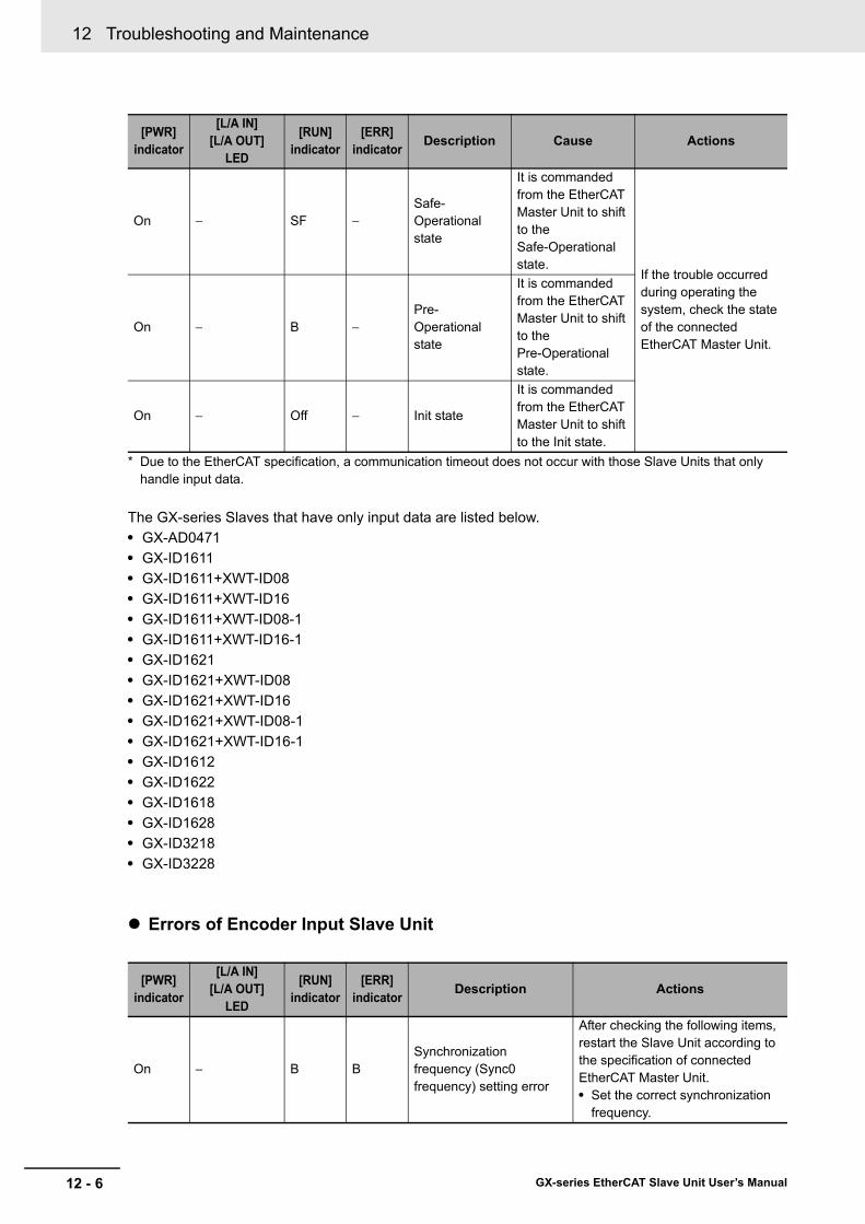
12 Troubleshooting and Maintenance
12 - 6 GX-series EtherCAT Slave Unit User’s Manual
* Due to the EtherCAT specification, a communication timeout does not occur with those Slave Units that only handle input data.
The GX-series Slaves that have only input data are listed below.• GX-AD0471• GX-ID1611• GX-ID1611+XWT-ID08• GX-ID1611+XWT-ID16• GX-ID1611+XWT-ID08-1• GX-ID1611+XWT-ID16-1• GX-ID1621• GX-ID1621+XWT-ID08• GX-ID1621+XWT-ID16• GX-ID1621+XWT-ID08-1• GX-ID1621+XWT-ID16-1• GX-ID1612• GX-ID1622• GX-ID1618• GX-ID1628• GX-ID3218• GX-ID3228
Errors of Encoder Input Slave Unit
On − SF −Safe-Operational state
It is commanded from the EtherCAT Master Unit to shift to the Safe-Operational state.
If the trouble occurred during operating the system, check the state of the connected EtherCAT Master Unit.
On − B −Pre-Operational state
It is commanded from the EtherCAT Master Unit to shift to the Pre-Operational state.
On − Off − Init state
It is commanded from the EtherCAT Master Unit to shift to the Init state.
[PWR] indicator
[L/A IN][L/A OUT]
LED
[RUN] indicator
[ERR] indicator Description Actions
On − B BSynchronization frequency (Sync0 frequency) setting error
After checking the following items, restart the Slave Unit according to the specification of connected EtherCAT Master Unit.• Set the correct synchronization
frequency.
[PWR] indicator
[L/A IN][L/A OUT]
LED
[RUN] indicator
[ERR] indicator Description Cause Actions

12 - 7
12 Troubleshooting and Maintenance
GX-series EtherCAT Slave Unit User’s Manual
12-1 Troubleshooting
12
12-1-2 Errors U
nique to Each S
lave Unit
On − B SFSynchronization error (at synchronization start)
After checking the following items, restart the Slave Unit according to the specification of connected EtherCAT Master Unit.• Is the communications cable
wired correctly?• Is the communications cable
exposed to excessive noise?• Review set time of Sync Not
Received Timeout Setting (synchronization error setting).
On − SF SFCommunications synchronization error
After checking the following items, restart the Slave Unit according to the specification of connected EtherCAT Master Unit.• Is the communications cable
wired correctly?• Is the communications cable
exposed to excessive noise?• Review set time of
Communication Error Setting .
On − SF SFSynchronization error (in operation)
After checking the following items, restart the Slave Unit according to the specification of connected EtherCAT Master Unit.• Is the communications cable
wired correctly?• Is the communications cable
exposed to excessive noise?• Review set time of
Communication Error Setting .If this does not improve, the Slave Unit hardware may be damaged. Replace the applicable Slave Unit.
12-1-2 Errors Unique to Each Slave Unit
Slave Unit type Symptom Cause Measures
All models other than Encoder Input Slave Units
Some functions are not reflected even after parameters have been set.
The functions enabled by recycling the power were changed.
Turn ON Slave Unit power supply again after changing the setting.
[PWR] indicator
[L/A IN][L/A OUT]
LED
[RUN] indicator
[ERR] indicator Description Actions

12 Troubleshooting and Maintenance
12 - 8 GX-series EtherCAT Slave Unit User’s Manual
Slave Units to which Expansion Units can be mounted
I/O communications stopped after mounting or removing an Expansion Unit and turning ON the power.
The number of I/O points increase or decrease when Expansion Units are mounted or removed. The number of I/O points may not conform to the I/O data assigned to the EtherCAT Master Unit.
Allocate I/O data again to the EtherCAT Master Unit.
The [PWR] indicator lights red after mounting or removing an Expansion Unit online.
Expansion Units cannot be mounted or removed online.
Turn OFF the power supply before mounting or removing Expansion Units.
Slave Units with digital inputs
Although a connected device is ON, nothing is input and Slave Unit's input indicator does not turn ON either.
The I/O power is not supplied.
Check that the I/O power is supplied.
I/O power supply voltage is outside the rated range.
Set the I/O power supply voltage within the rated voltage.
Wiring with the connected device is incorrect.
Check the wiring with the connected device.
Terminal block screws are loosened. (Terminal block type only)
Check if terminal block screws are loosened.
A connected device is disconnected.
Check the wiring with the connected device.
A connected device is defective.
Replace the connected device.
A connected device is ON and Slave Unit's input indicator is turned ON, but nothing is input.
A communications error occurred.
Check if a communications error occurred.
There is a delay with the ON and OFF timing for input values.
An input filter may be set.
Set the input filter value to 0. Alternatively, change the input filter to an appropriate value.
Slave Unit type Symptom Cause Measures

12 - 9
12 Troubleshooting and Maintenance
GX-series EtherCAT Slave Unit User’s Manual
12-1 Troubleshooting
12
12-1-2 Errors U
nique to Each S
lave Unit
Slave Units with digital outputs
When the output is ON, nothing is output although the output indicator is turned ON.
The I/O power is not supplied.
Check that the I/O power is supplied.
I/O power supply voltage is outside the rated range.
Set the I/O power supply voltage within the rated voltage.
Wiring with the connected device is incorrect.
Check the wiring with the connected device.
Terminal block screws are loosened. (Terminal block type only)
Check if terminal block screws are loosened.
A connected device is disconnected.
Check the wiring with the connected device.
A connected device is defective.
Replace the connected device.
Although the output is ON, nothing is output and Slave Unit's output indicator does not turn ON either.
A communications error occurred.
Check if a communications error occurred.
Cannot hold outputs when communications errors occur.
The Unit is set to clear outputs at communications errors.
Change the setting to hold outputs at communications errors.
Cannot clear outputs when communications errors occur.
The Unit is set to hold outputs at communications errors.
Change the setting to clear outputs at communications errors.
Analog I/O Slave Units
The analog data values are different from expected or the analog data error is too large.
The user adjustment error is too large.
Execute user adjustment again.
Even if the I/O range setting is changed, expected analog input value is not set. Alternatively, expected analog value is not output.
Setting changes are not reflected unless the unit power supply is turned ON again after making changes.
Turn ON the unit power supply again after changing the setting.
The I/O range cannot be set with the range setting switch.
The Pin8 is turned OFF (to allow the setting via SDO communications). This is the default setting.
Turn Pin8 ON (to allow the setting via range setting switch).
Slave Unit type Symptom Cause Measures

12 Troubleshooting and Maintenance
12 - 10 GX-series EtherCAT Slave Unit User’s Manual
Analog input Slave Unit
The disconnection indication does not clear.
The sensor is disconnected.
Restore the sensor connection.Check the connected sensor and input type.
Disconnection is not detected.
Disconnection can not be detected for ranges other than 1 to 5 V and 4 to 20 mA.
Check that the input range is correct.
A disconnection is detected even though it is not disconnected.
The connected sensor does not conform to the input range set on the Unit.
Check the type of connected sensor and the range setting on the Slave Unit again.
The user adjustment error is too large.
Execute user adjustment again.
The conversion cycle is too long.
The number of AD conversion points is set to maximum (4 points).
Reduce the number of points if some inputs are unnecessary, and execute conversion again.
User adjustment is not accepted.
Attempted to make adjustment with inputs outside the compensation range.
Enter a voltage (current) within the compensation range with the input device and make adjustment again.If a voltage (current) within the compensation range cannot be entered, check the method being used to connect the input device.
Analog output Slave Unit
Cannot hold expected outputs when communications errors occur.
The output value that is set for communications errors is incorrect.
Change the setting to hold outputs for communications errors.
The conversion cycle is too long.
The number of DA conversion points is set to maximum (2 points).
Reduce the number of points if some outputs are unnecessary, and execute conversion again.
User adjustment is not accepted.
Attempted to make adjustment with values outside the compensation range.
Use a voltage (current) within the setting range to make adjustment again.If the final output cannot be adjusted within the correctable range, check the method being used to connect to the output device.
Slave Unit type Symptom Cause Measures

12 - 11
12 Troubleshooting and Maintenance
GX-series EtherCAT Slave Unit User’s Manual
12-1 Troubleshooting
12
12-1-2 Errors U
nique to Each S
lave Unit
Encoder Input Slave Unit
The count pulse cannot be detected.
Input wiring is wrong. Check wiring of input A and input B.
The I/O power is not supplied.
Check that the I/O power is supplied.
I/O power supply voltage is outside the rated range.
Set the I/O power supply voltage within the rated voltage.
A connected device is disconnected.
Check the wiring with the connected device.
A connected device is defective.
Replace the connected device.
The setting of counter input method is wrong.
Set the correct counter input method and restart the Slave Unit.
The pulse is not counted accurately.
The pulse frequency exceeds the maximum frequency of the Slave Unit specification.Or, the frequency exceeds the maximum value of set mode.
Set the pulse frequency within the Slave Unit specification or the mode maximum value.
The setting of counter input method is wrong.
Set the correct counter input method and restart the Slave Unit.
The counter value is not reset even the present value external reset signal or phase Z pulse are input.
Input wiring is wrong. Check input wiring.The soft switch "present value external reset enabled" is set to 0 (disabled).
Set the soft switch "present value external reset enabled" to 1 (enabled).
Counting is not possible. (The count value cannot be reset with external input when counting is not possible.)
Change to count possible status. If it is necessary to reset because counting is not possible, reset with the soft switch "present value internal reset execution."
Although the soft switch "present value external reset enabled" is enabled, the counter value cannot be reset even if signals are input.
After resetting the counter value externally, the "external reset generation flag" changes from 0 to 1. After that, external reset cannot be performed until the flag is cleared.
Change the soft switch "clear present value external reset generation flag" from 0 to 1.At the rise from 0 to 1, the "external reset generation flag" changes from 1 to 0 and external reset is enabled.
The counter value cannot be latched even if external control input (latch A/B) signals are input.
The soft switch "external latch A/B enabled" is set to 0 (disabled).
Set the soft switch "external latch A/B enabled" to 1 (enabled).
Although the soft switch "external latch A/B enabled" is enabled, the counter value cannot be latched even if signals are input.
After latching the counter value, the "external latch A/B generation flag" changes from 0 to 1. After that, it is not possible to latch until the flag is cleared.
Change the soft switch "clear external latch A/B generation flag" from 0 to 1. At the rise from 0 to 1, the "external latch A/B generation flag" changes from 1 to 0 and latch is enabled.
Slave Unit type Symptom Cause Measures
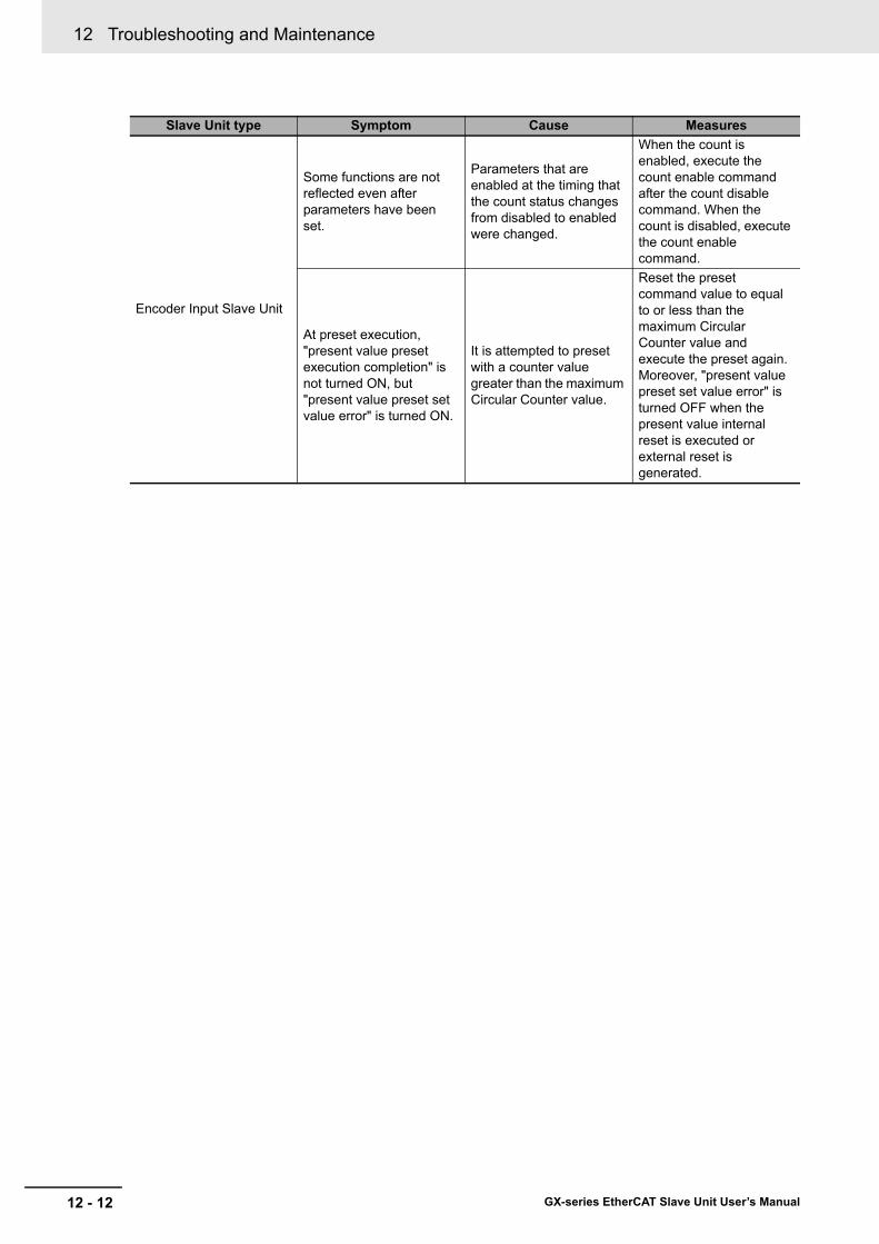
12 Troubleshooting and Maintenance
12 - 12 GX-series EtherCAT Slave Unit User’s Manual
Encoder Input Slave Unit
Some functions are not reflected even after parameters have been set.
Parameters that are enabled at the timing that the count status changes from disabled to enabled were changed.
When the count is enabled, execute the count enable command after the count disable command. When the count is disabled, execute the count enable command.
At preset execution, "present value preset execution completion" is not turned ON, but "present value preset set value error" is turned ON.
It is attempted to preset with a counter value greater than the maximum Circular Counter value.
Reset the preset command value to equal to or less than the maximum Circular Counter value and execute the preset again.Moreover, "present value preset set value error" is turned OFF when the present value internal reset is executed or external reset is generated.
Slave Unit type Symptom Cause Measures

12 - 13
12 Troubleshooting and Maintenance
GX-series EtherCAT Slave Unit User’s Manual
12-1 Troubleshooting
12
12-1-3 Error N
otification Methods and Types
This section describes the notification methods for errors that occur in the Slave Units.
12-1-3 Error Notification Methods and Types
Error notification type Description Notification method Page
Sysmac error status
Notification is provided when an error is detected in the application. These errors are displayed only on the OMRON Sysmac Studio Support Software.
Error status is received by the TxPDO and the master is notified of errors every cycle.
"12-1-4 Sysmac Error Status Codes" in page 12 - 14
Emergency messages
Notification is provided of application-level errors. Either CiA-defined error codes are used or error codes are added to vendor-specific areas.
The slave notifies the master when an error occurs.
"12-1-5 Emergency Error Code" in page 12 - 19
Application layer status
Notification is provided of errors in EtherCAT communications. The error notification method and error codes that are defined by ETG are used.
The master is notified by writing to the application layer status register when an error occurs.
"12-1-6 Application Layer Status Codes" in page 12 - 21
Emergency message
Sysmac error status
Application layer status
Error occurs.
Master notified.
Diagnosis history
ID211
01
32
45
76
89
1110
1213
1415
DC24V7mA
COM
MACHNo.
AD042RUNERCERH
B1 A1
x101
x100
0
9876
5
4 321
0
9876
5
4 321
0 1 2 3 4 5 6 78 9 10 11 12 13 14 15
EtherCAT Slave Unit
EtherCAT Master Unit
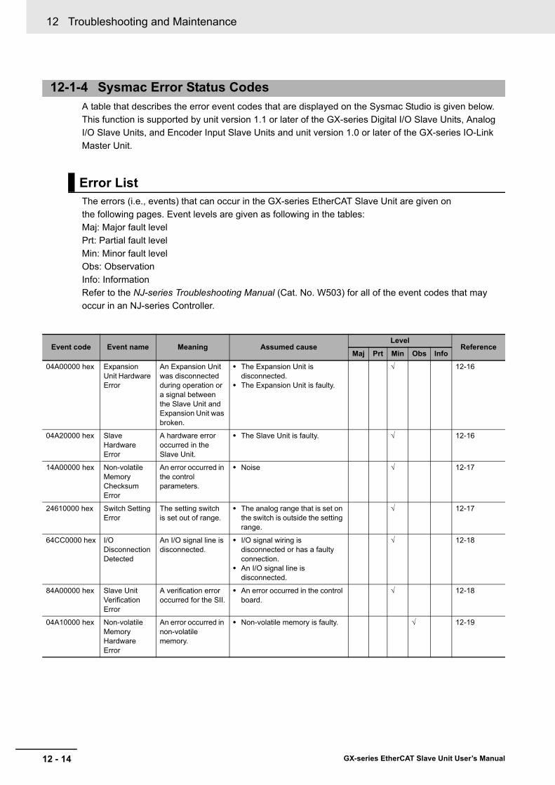
12 Troubleshooting and Maintenance
12 - 14 GX-series EtherCAT Slave Unit User’s Manual
A table that describes the error event codes that are displayed on the Sysmac Studio is given below.This function is supported by unit version 1.1 or later of the GX-series Digital I/O Slave Units, Analog I/O Slave Units, and Encoder Input Slave Units and unit version 1.0 or later of the GX-series IO-Link Master Unit.
The errors (i.e., events) that can occur in the GX-series EtherCAT Slave Unit are given onthe following pages. Event levels are given as following in the tables:Maj: Major fault levelPrt: Partial fault levelMin: Minor fault levelObs: ObservationInfo: InformationRefer to the NJ-series Troubleshooting Manual (Cat. No. W503) for all of the event codes that mayoccur in an NJ-series Controller.
12-1-4 Sysmac Error Status Codes
Error List
Event code Event name Meaning Assumed causeLevel
ReferenceMaj Prt Min Obs Info
04A00000 hex Expansion Unit Hardware Error
An Expansion Unit was disconnected during operation or a signal between the Slave Unit and Expansion Unit was broken.
• The Expansion Unit is disconnected.
• The Expansion Unit is faulty.
√ 12-16
04A20000 hex Slave Hardware Error
A hardware error occurred in the Slave Unit.
• The Slave Unit is faulty. √ 12-16
14A00000 hex Non-volatile Memory Checksum Error
An error occurred in the control parameters.
• Noise √ 12-17
24610000 hex Switch Setting Error
The setting switch is set out of range.
• The analog range that is set on the switch is outside the setting range.
√ 12-17
64CC0000 hex I/O Disconnection Detected
An I/O signal line is disconnected.
• I/O signal wiring is disconnected or has a faulty connection.
• An I/O signal line is disconnected.
√ 12-18
84A00000 hex Slave Unit Verification Error
A verification error occurred for the SII.
• An error occurred in the control board.
√ 12-18
04A10000 hex Non-volatile Memory Hardware Error
An error occurred in non-volatile memory.
• Non-volatile memory is faulty. √ 12-19

12 - 15
12 Troubleshooting and Maintenance
GX-series EtherCAT Slave Unit User’s Manual
12-1 Troubleshooting
12
12-1-4 Sysm
ac Error Status C
odes
This section describes the information that is given for individual errors.
Controller Error DescriptionsThe items that are used to describe individual errors (events) are described in the following copy of an error table.
*1 One of the following:Major fault: Major fault levelPartial fault: Partial fault levelMinor fault: Minor fault levelObservationInformation
*2 One of the following:Automatic recovery: Normal status is restored automatically when the cause of the error is removed.Error reset: Normal status is restored when the error is reset after the cause of the error is removed.Cycle the power supply: Normal status is restored when the power supply to the Controller is turned OFF and then backON after the cause of the error is removed.Controller reset: Normal status is restored when the Controller is reset after the cause of the error is removed.Depends on cause: The recovery method depends on the cause of the error.
*3 One of the following:System: System event logAccess: Access event log
*4 One of the following:Continues: Execution of the user program will continue.Stops: Execution of the user program stops.Starts: Execution of the user program starts.
Error Descriptions
Event name Gives the name of the error. Event code Gives the code of the error.
Meaning Gives a short description of the error.
Source Gives the source of the error. Source details Gives details on the source of the error.
Detection timing Tells when the error is detected.
Error attributes Level Tells the level of influence on control.*1
Recovery Gives the recovery method.*2
Log category Tells which log the error is saved in.*3
Effects User program Tells what will happen to execution of the user program.*4
Operation Provides special information on the operation that results from the error.
Indicators Gives the status of the built-in EtherNet/IP port and built-in EtherCAT port indicators. Indicator status is given only for errors in the EtherCAT Master Function Module and the EtherNet/IP Function Module.
System-defined variables
Variable name Data type Meaning
Lists the variable names, data types, and meanings for system-defined variables that provide direct error notification, that are directly affected by the error, or that contain settings that cause the error.
Cause and correction
Assumed cause Correction Prevention
Lists the possible causes, corrections, and preventive measures for the error.
Attached information
This is the attached information that is displayed by the Sysmac Studio or an NS-series PT.
Precautions/Remarks
Provides precautions, restrictions, and supplemental information.
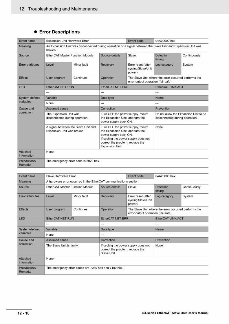
12 Troubleshooting and Maintenance
12 - 16 GX-series EtherCAT Slave Unit User’s Manual
Error Descriptions
Event name Expansion Unit Hardware Error Event code 04A00000 hex
Meaning An Expansion Unit was disconnected during operation or a signal between the Slave Unit and Expansion Unit was broken.
Source EtherCAT Master Function Module Source details Slave Detection timing
Continuously
Error attributes Level Minor fault Recovery Error reset (after cycling Slave Unit power)
Log category System
Effects User program Continues Operation The Slave Unit where the error occurred performs the error output operation (fail-safe).
LED EtherCAT NET RUN EtherCAT NET ERR EtherCAT LINK/ACT
--- --- ---
System-defined variables
Variable Data type Name
None --- ---
Cause and correction
Assumed cause Correction Prevention
The Expansion Unit was disconnected during operation.
Turn OFF the power supply, mount the Expansion Unit, and turn the power supply back ON.
Do not allow the Expansion Unit to be disconnected during operation.
A signal between the Slave Unit and Expansion Unit was broken.
Turn OFF the power supply, mount the Expansion Unit, and turn the power supply back ON.If cycling the power supply does not correct the problem, replace the Expansion Unit.
None
Attached information
None
Precautions/Remarks
The emergency error code is 5020 hex.
Event name Slave Hardware Error Event code 04A20000 hex
Meaning A hardware error occurred in the EtherCAT communications section.
Source EtherCAT Master Function Module Source details Slave Detection timing
Continuously
Error attributes Level Minor fault Recovery Error reset (after cycling Slave Unit power)
Log category System
Effects User program Continues Operation The Slave Unit where the error occurred performs the error output operation (fail-safe).
LED EtherCAT NET RUN EtherCAT NET ERR EtherCAT LINK/ACT
--- --- ---
System-defined variables
Variable Data type Name
None --- ---
Cause and correction
Assumed cause Correction Prevention
The Slave Unit is faulty. If cycling the power supply does not correct the problem, replace the Slave Unit.
None
Attached information
None
Precautions/Remarks
The emergency error codes are 7030 hex and 7100 hex.

12 - 17
12 Troubleshooting and Maintenance
GX-series EtherCAT Slave Unit User’s Manual
12-1 Troubleshooting
12
12-1-4 Sysm
ac Error Status C
odes
Event name Non-volatile Memory Checksum Error Event code 14A00000 hex
Meaning An error occurred in the control parameters.
Source EtherCAT Master Function Module Source details Slave Detection timing
When establishing communications after turning ON power to the Slave Unit
Error attributes Level Minor fault Recovery Error reset (after cycling Slave Unit power)
Log category System
Effects User program Continues Operation The Slave Unit’s I/O communications stop and the outputs turn OFF.
LED EtherCAT NET RUN EtherCAT NET ERR EtherCAT LINK/ACT
--- Flashes at 1-s intervals. ---
System-defined variables
Variable Data type Name
None --- ---
Cause and correction
Assumed cause Correction Prevention
Noise Return the control parameters to their default settings using restore parameters (1011 hex) of the EtherCAT Slave Unit.
Implement noise countermeasures.
Attached information
None
Precautions/Remarks
The emergency error code is 6330 hex.
Event name Switch Setting Error Event code 24610000 hex
Meaning The setting switch is set out of range.
Source EtherCAT Master Function Module Source details Slave Detection timing
When establishing communications after turning ON power to the Slave Unit
Error attributes Level Minor fault Recovery Error reset (after cycling Slave Unit power)
Log category System
Effects User program Continues Operation The Slave Unit’s I/O communications stop and the outputs turn OFF.
LED EtherCAT NET RUN EtherCAT NET ERR EtherCAT LINK/ACT
OFF Flashes at 1-s intervals. ---
System-defined variables
Variable Data type Name
None --- ---
Cause and correction
Assumed cause Correction Prevention
The analog range that is set on the switch is outside the setting range.
Make sure that switch settings are within the specified range.
Make sure that switch settings are correct.
Attached information
None
Precautions/Remarks
The emergency error code is 5600 hex.
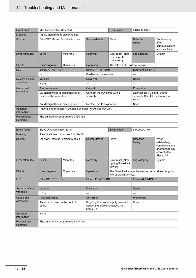
12 Troubleshooting and Maintenance
12 - 18 GX-series EtherCAT Slave Unit User’s Manual
Event name I/O Disconnection Detected Event code 64CC0000 hex
Meaning An I/O signal line is disconnected.
Source EtherCAT Master Function Module Source details Slave Detection timing
Continuously after communications are established
Error attributes Level Minor fault Recovery Error reset (after resetting Slave Unit errors)
Log category System
Effects User program Continues Operation The relevant I/O will not operate.
LED EtherCAT NET RUN EtherCAT NET ERR EtherCAT LINK/ACT
--- Flashes at 1-s intervals. ---
System-defined variables
Variable Data type Name
None --- ---
Cause and correction
Assumed cause Correction Prevention
I/O signal wiring is disconnected or has a faulty connection.
Connect the I/O signal wiring securely.
Connect the I/O signal wiring securely. Check for vibration and shock.
An I/O signal line is disconnected. Replace the I/O signal line. None
Attached information
Attached information 1: Detected channel (for Analog I/O Unit)
Precautions/Remarks
The emergency error code is 2130 hex.
Event name Slave Unit Verification Error Event code 84A00000 hex
Meaning A verification error occurred for the SII.
Source EtherCAT Master Function Module Source details Slave Detection timing
When establishing communications after turning ON power to the Slave Unit
Error attributes Level Minor fault Recovery Error reset (after cycling Slave Unit power)
Log category System
Effects User program Continues Operation The Slave Unit where the error occurred does not go to Pre-operational state.
LED EtherCAT NET RUN EtherCAT NET ERR EtherCAT LINK/ACT
--- --- ---
System-defined variables
Variable Data type Name
None --- ---
Cause and correction
Assumed cause Correction Prevention
An error occurred in the control board.
If cycling the power supply does not correct the problem, replace the Slave Unit.
None
Attached information
None
Precautions/Remarks
The emergency error code is 6140 hex.
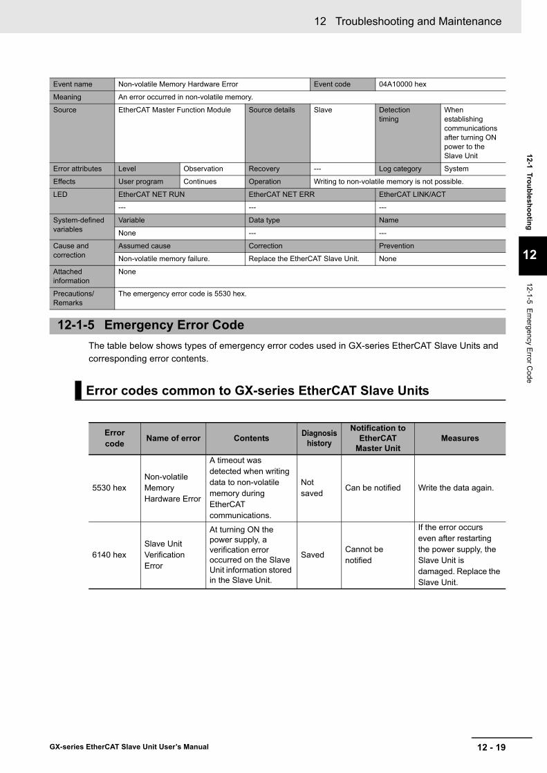
12 - 19
12 Troubleshooting and Maintenance
GX-series EtherCAT Slave Unit User’s Manual
12-1 Troubleshooting
12
12-1-5 Em
ergency Error C
ode
The table below shows types of emergency error codes used in GX-series EtherCAT Slave Units and corresponding error contents.
Event name Non-volatile Memory Hardware Error Event code 04A10000 hex
Meaning An error occurred in non-volatile memory.
Source EtherCAT Master Function Module Source details Slave Detection timing
When establishing communications after turning ON power to the Slave Unit
Error attributes Level Observation Recovery --- Log category System
Effects User program Continues Operation Writing to non-volatile memory is not possible.
LED EtherCAT NET RUN EtherCAT NET ERR EtherCAT LINK/ACT
--- --- ---
System-defined variables
Variable Data type Name
None --- ---
Cause and correction
Assumed cause Correction Prevention
Non-volatile memory failure. Replace the EtherCAT Slave Unit. None
Attached information
None
Precautions/Remarks
The emergency error code is 5530 hex.
12-1-5 Emergency Error Code
Error codes common to GX-series EtherCAT Slave Units
Errorcode Name of error Contents Diagnosis
history
Notification to EtherCAT
Master UnitMeasures
5530 hexNon-volatile Memory Hardware Error
A timeout was detected when writing data to non-volatile memory during EtherCAT communications.
Not saved
Can be notified Write the data again.
6140 hexSlave Unit Verification Error
At turning ON the power supply, a verification error occurred on the Slave Unit information stored in the Slave Unit.
SavedCannot be notified
If the error occurs even after restarting the power supply, the Slave Unit is damaged. Replace the Slave Unit.

12 Troubleshooting and Maintenance
12 - 20 GX-series EtherCAT Slave Unit User’s Manual
6330 hex
Non-volatile Memory Checksum Error
An error occurred in non-volatile memory data in the Slave Unit.
Saved Can be notified
A non-volatile memory data error occurred. Initialize non-volatile memory from a Configuration Tool or with SDO communications, and then restart the Slave Unit. (Target indexes: 1011 hex Restore default parameters (parameter restore))
7030 hexSlave Hardware Error
A hardware error occurred in the EtherCAT communications area.
SavedCannot be notified
If the error occurs even after restarting the power supply, the Slave Units is damaged. Replace the Slave Units.
Error codes unique to Digital I/O Slave Unit
Errorcode Name of error Contents Diagnosis
history
Notification to EtherCAT
Master UnitMeasures
5020 hexExpansion Unit Hardware Error
Expansion Unit hardware errors
Saved Cannot be notified
The Expansion Unit is disconnected. Check the Expansion Unit connection.If the error is displayed again, the Expansion Unit is damaged. Replace the Expansion Unit.
Error codes unique to Analog I/O Slave Unit
Errorcode Name of error Contents Diagnosis
history
Notification to EtherCAT
Master UnitMeasures
2130 hexI/O Disconnection Detected
A broken analog input line was detected.
Not saved
Can be notified
Check the slave voltage or current input line to see if it is broken.
5600 hexSwitch Setting Error
A range setting switch setting is illegal.
Not saved
Can be notifiedSet the range setting switch correctly and restart the Slave Unit.
Errorcode Name of error Contents Diagnosis
history
Notification to EtherCAT
Master UnitMeasures
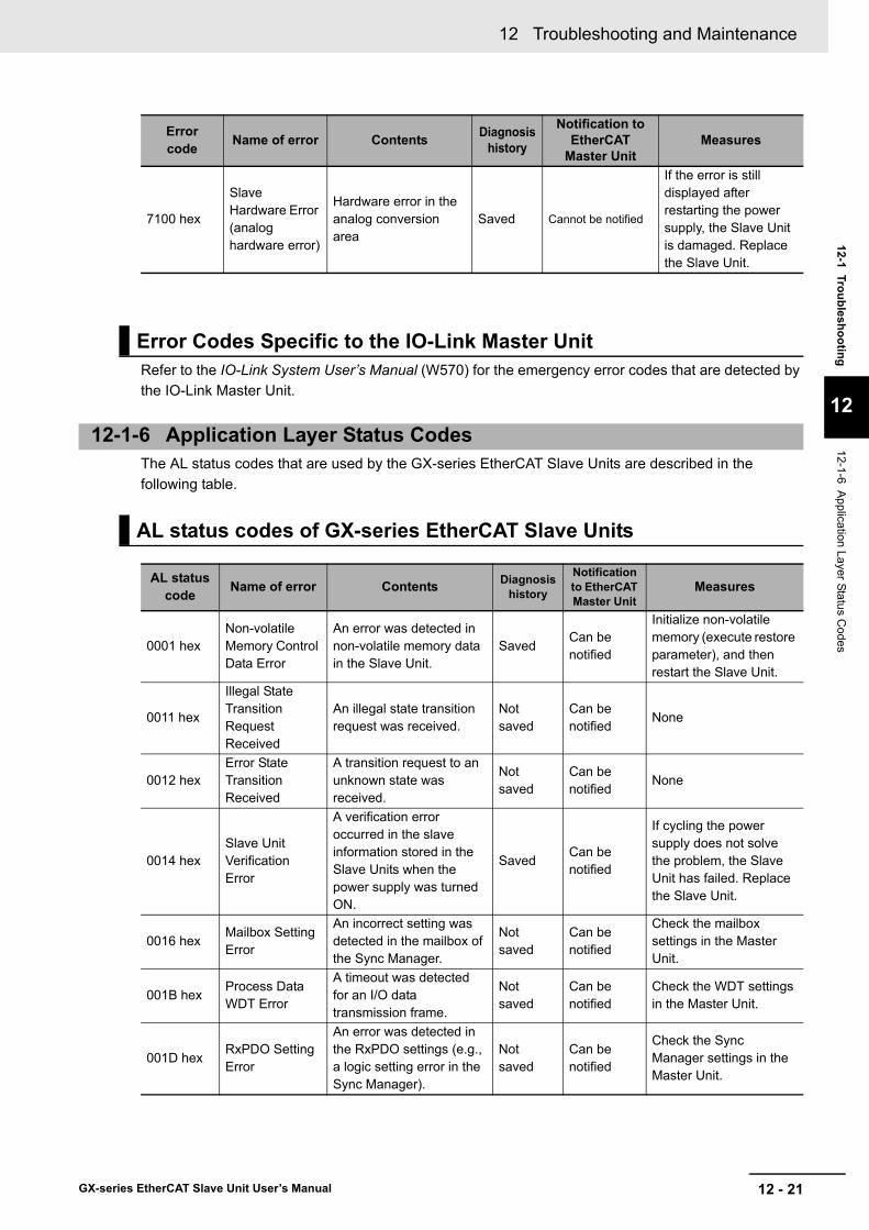
12 - 21
12 Troubleshooting and Maintenance
GX-series EtherCAT Slave Unit User’s Manual
12-1 Troubleshooting
12
12-1-6 Application Layer Status C
odes
Refer to the IO-Link System User’s Manual (W570) for the emergency error codes that are detected by the IO-Link Master Unit.
The AL status codes that are used by the GX-series EtherCAT Slave Units are described in the following table.
7100 hex
Slave Hardware Error (analog hardware error)
Hardware error in the analog conversion area
Saved Cannot be notified
If the error is still displayed after restarting the power supply, the Slave Unit is damaged. Replace the Slave Unit.
Error Codes Specific to the IO-Link Master Unit
12-1-6 Application Layer Status Codes
AL status codes of GX-series EtherCAT Slave Units
AL status code Name of error Contents Diagnosis
history
Notification to EtherCAT Master Unit
Measures
0001 hexNon-volatile Memory Control Data Error
An error was detected in non-volatile memory data in the Slave Unit.
SavedCan be notified
Initialize non-volatile memory (execute restore parameter), and then restart the Slave Unit.
0011 hex
Illegal State Transition Request Received
An illegal state transition request was received.
Not saved
Can be notified
None
0012 hexError State Transition Received
A transition request to an unknown state was received.
Not saved
Can be notified
None
0014 hexSlave Unit Verification Error
A verification error occurred in the slave information stored in the Slave Units when the power supply was turned ON.
SavedCan be notified
If cycling the power supply does not solve the problem, the Slave Unit has failed. Replace the Slave Unit.
0016 hexMailbox Setting Error
An incorrect setting was detected in the mailbox of the Sync Manager.
Not saved
Can be notified
Check the mailbox settings in the Master Unit.
001B hexProcess Data WDT Error
A timeout was detected for an I/O data transmission frame.
Not saved
Can be notified
Check the WDT settings in the Master Unit.
001D hexRxPDO Setting Error
An error was detected in the RxPDO settings (e.g., a logic setting error in the Sync Manager).
Not saved
Can be notified
Check the Sync Manager settings in the Master Unit.
Errorcode Name of error Contents Diagnosis
history
Notification to EtherCAT
Master UnitMeasures
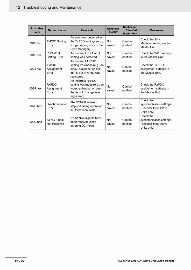
12 Troubleshooting and Maintenance
12 - 22 GX-series EtherCAT Slave Unit User’s Manual
001E hexTxPDO Setting Error
An error was detected in the TxPDO settings (e.g., a logic setting error in the Sync Manager).
Not saved
Can be notified
Check the Sync Manager settings in the Master Unit.
001F hexPDO WDT Setting Error
An incorrect PDO WDT setting was detected.
Not saved
Can be notified
Check the WDT settings in the Master Unit.
0024 hexTxPDO Assignment Error
An incorrect TxPDO setting was made (e.g., an index, subindex, or size that is out of range was registered).
Not saved
Can be notified
Check the TxPDO assignment settings in the Master Unit.
0025 hexRxPDO Assignment Error
An incorrect RxPDO setting was made (e.g., an index, subindex, or size that is out of range was registered).
Not saved
Can be notified
Check the RxPDO assignment settings in the Master Unit.
002C hexSynchronization Error
The SYNC0 interrupt stopped during operation in Operational state.
Not saved
Can be notified
Check the synchronization settings. (Encoder Input Slave Units only)
002D hexSYNC Signal Not Received
No SYNC0 signals have been received since entering DC mode.
Not saved
Can be notified
Check the synchronization settings. (Encoder Input Slave Units only)
AL status code Name of error Contents Diagnosis
history
Notification to EtherCAT Master Unit
Measures
12 - 23
12 Troubleshooting and Maintenance
GX-series EtherCAT Slave Unit User’s Manual
12-2 Equipment M
aintenance
12
12-2-1 Cleaning
12-2 Equipment Maintenance
This section describes routine equipment maintenance, in particular cleaning methods, inspection methods, and handling methods when replacing Slave Units.
Perform the following cleaning regularly to ensure the equipment is kept in the best condition possible.• Wipe the equipment over with a soft, dry cloth when doing daily cleaning.• If dirt remains even after wiping with a soft, dry cloth, wipe over with a cloth that has been wet with a
sufficiently diluted detergent (2%) and wrung dry.• Units will become stained if items such as rubber or vinyl products or adhesive tape are left on the
Unit for a long period. Remove such items during regular cleaning.
Precautions for Correct Use
Never use benzene, thinners, or other volatile solvents, or chemical cloths.The unit coating may change if these products are used.
Always perform periodic inspections to ensure the equipment is kept in the best possible condition.Periodic inspections should occur every 6 months to a year.Periodic inspections should occur more frequently, however, for Units that are used in environments subject to high temperatures, high humidity, or a lot of dust.
The following materials are required to perform periodic inspections.
Materials used regularly• Phillips screwdrivers and flat-blade screwdrivers• Screwdrivers for communications connectors• Testers (or digital voltmeters)• Industrial alcohol and pure cotton cloth
Materials sometimes required• Synchroscope• Pen oscilloscope• Thermometer and hygrometer
12-2-1 Cleaning
12-2-2 Inspections
Materials required for inspections

12 Troubleshooting and Maintenance
12 - 24 GX-series EtherCAT Slave Unit User’s Manual
Periodically inspect the following items to ensure that they do not deviate from the criteria.If the items deviate from the criteria, adjust the environment so the criteria are met or adjust the Unit itself.
Networks are constructed from an EtherCAT Master Unit and Slave Units. If a Unit is malfunctioning, the entire network will be affected. The malfunctioning Unit must be replaced quickly.To restore network functions as quickly as possible, it is recommended that spare Units are kept on hand ready to replace malfunctioning Units immediately.
Heed the following precautions when replacing nodes after a periodic inspection has revealed a problem.• Check that the new Unit does not have errors after replacement.• If returning malfunctioning devices for repair, attach a detailed description of the malfunction to the
device and send the device to the OMRON representative listed at the end of this manual or to your OMRON representative.
• If contacts are defective, wipe them with a clean pure cotton cloth that has been soaked in industrial alcohol.
After replacing a Unit, make the switch and other settings the same as before the Unit was replaced.
Refer to the IO-Link System User’s Manual (W570) for information on replacing an IO-Link Master Unit.
Inspection item
Inspection item Inspection details Criteria Inspection
method
Environment
Are the ambient and in-panel temperatures appropriate?
−10 to 55°C Thermometer
Is the ambient and in-panel humidity appropriate?
25 to 85% (with no condensation)
Hygrometer
Has dust collected? No dust Visual inspection
Installation
Has the Slave Unit been secured? No looseness Phillips screwdriverAre the communications cable connectors inserted properly?
No looseness Visual inspection
Are the external wiring screws loose? No looseness Phillips screwdriverAre the connection cables damaged? No visible damage Visual inspection
12-2-3 Handling when Replacing Units
Precautions when replacing Units
Settings after Unit replacement
12-2-4 Replacing the IO-Link Master Unit or IO-Link Devices

A - 1
A
GX-series EtherCAT Slave Unit User’s Manual
A-1 Object Dictionary . . . . . . . . . . . . . . . . . . . . . . . . . . . . . . . . . . . . . . . . . . . . . . A-2A-1-1 Object Dictionary Area . . . . . . . . . . . . . . . . . . . . . . . . . . . . . . . . . . . . . . . . . . . A-2A-1-2 Data Types . . . . . . . . . . . . . . . . . . . . . . . . . . . . . . . . . . . . . . . . . . . . . . . . . . . . A-2A-1-3 Object Description Format . . . . . . . . . . . . . . . . . . . . . . . . . . . . . . . . . . . . . . . . A-3A-1-4 Communication Objects . . . . . . . . . . . . . . . . . . . . . . . . . . . . . . . . . . . . . . . . . . A-4A-1-5 PDO Mapping Object . . . . . . . . . . . . . . . . . . . . . . . . . . . . . . . . . . . . . . . . . . . . A-8A-1-6 Sync Manager Communication Object . . . . . . . . . . . . . . . . . . . . . . . . . . . . . . A-24A-1-7 Manufacturer Specific Objects . . . . . . . . . . . . . . . . . . . . . . . . . . . . . . . . . . . . A-29
A-2 Current Consumption Summary . . . . . . . . . . . . . . . . . . . . . . . . . . . . . . . . . A-67A-2-1 Digital I/O Slave Unit . . . . . . . . . . . . . . . . . . . . . . . . . . . . . . . . . . . . . . . . . . . . A-67A-2-2 Analog I/O Slave Unit . . . . . . . . . . . . . . . . . . . . . . . . . . . . . . . . . . . . . . . . . . . A-67A-2-3 Encoder Input Slave Unit . . . . . . . . . . . . . . . . . . . . . . . . . . . . . . . . . . . . . . . . A-67A-2-4 IO-Link Master Unit . . . . . . . . . . . . . . . . . . . . . . . . . . . . . . . . . . . . . . . . . . . . . A-68A-2-5 Expansion Unit . . . . . . . . . . . . . . . . . . . . . . . . . . . . . . . . . . . . . . . . . . . . . . . . A-68
A-3 Precautions with Connecting Two-wire DC Sensors . . . . . . . . . . . . . . . . A-69A-3-1 Relation between ON Voltage of a Unit with DC Inputs and Sensor Residual
Voltage . . . . . . . . . . . . . . . . . . . . . . . . . . . . . . . . . . . . . . . . . . . . . . . . . . . . . . A-69A-3-2 Relation between ON Current of a Unit with DC Inputs and Sensor Control Output . A-69A-3-3 Relation between OFF Current of a Unit with DC Inputs and Sensor Leakage
Current . . . . . . . . . . . . . . . . . . . . . . . . . . . . . . . . . . . . . . . . . . . . . . . . . . . . . . A-70
A-4 Wiring External Output Signal Lines . . . . . . . . . . . . . . . . . . . . . . . . . . . . . A-71A-5 I/O Power Supply Current . . . . . . . . . . . . . . . . . . . . . . . . . . . . . . . . . . . . . . A-72A-6 Glossary . . . . . . . . . . . . . . . . . . . . . . . . . . . . . . . . . . . . . . . . . . . . . . . . . . . . A-74
Appendix

A Appendix
A - 2 GX-series EtherCAT Slave Unit User’s Manual
A-1 Object Dictionary
The CAN application protocol over EtherCAT (CoE) protocol uses the object dictionary of CAN application protocol as its base. Each object is assigned with an index of four-digit hexadecimal value. The indexes are configured in the areas below.
This profile uses the following data types.
A-1-1 Object Dictionary Area
Indexes Area Contents0000 hex-0FFF hex Data Type area Definitions of data types
1000 hex-1FFF hex CoE Communications areaDefinitions of variables that can be used by all servers for designated communications
2000 hex-2FFF hex Manufacturer Specific area 1 Variables defined for all OMRON products
3000 hex-5FFF hex Manufacturer Specific area 2Variables defined for GX-series EtherCAT Slave Units
6000 hex-9FFF hex Device Profile area
Variables defined for CiA401 generic I/O module device profiles (profile specifying the CAN application protocol interface for devices with digital I/Os and analog I/Os)
A000 hex-FFFF hex Reserved area Area reserved for future use
A-1-2 Data Types
Data Types Code Size RangeBoolean BOOL 1 bit true(1), false(0)Unsigned8 U8 1 byte 0 to 255Unsigned16 U16 2 bytes 0 to 65535Unsigned32 U32 4 bytes 0 to 4294967295Integer8 INT8 1 byte −128 to 127Integer16 INT16 2 bytes −32768 to 32767Integer32 INT32 4 bytes −2147483648 to 2147483647ARRAY[0..1] OF BYTE − 2 bytes −Visible string VS − −

A - 3
A Appendix
GX-series EtherCAT Slave Unit User’s Manual
A-1 O
bject Dictionary
A
A-1-3 O
bject Description Form
at
In this manual, objects are described in the following format.
The following values are indicated within the pointed brackets <>.
A-1-3 Object Description Format
Object description format
<Index> <Object name>Range: <Setting range> Unit: <Unit> Default: <Default setting> Attribute: <Data attribute>Size: <Size> Access: <Access> PDO map: <Possible/Not possible>
Object description format with sub-indexes
<Index> <Object name>Sub-index 0Range: <Setting range> Unit: <Unit> Default: <Default setting> Attribute: <Data attribute>Size: <Size> Access: <Access> PDO map: <Possible/Not possible> • • •Sub-index NRange: <Setting range> Unit: <Unit> Default: <Default setting> Attribute: <Data attribute>Size: <Size> Access: <Access> PDO map: <Possible/Not possible>
Indexes : An object index given by a four-digit hexadecimal numberObject name : The object nameRange : The possible range of settingsUnit : Physical unitDefault : Default value set before product shipmentAttribute : The data attribute of a writable object
The data attribute is given in the following format.* ( : Indicates the timing when a change is applied.)
(*: Indicates whether the data is saved to non-volatile memory.)
Timing When a Change Is AppliedA: Enabled at any time.B: Enabled when moving from count stop status to operation status (Encoder Input
Slave Units only).C: Enabled when moving from Pre-Operational state to Safe-Operational state.D: Enabled when moving from Pre-Operational state to Init state.R: Enabled when power is reset.-: Read-only
Saving to Non-volatile MemoryWith asterisk (*): Saved to non-volatile memory.Without asterisk (*): Not saved to non-volatile memory.
Size : The object size is given in bytesAccess : Indicates whether the object is read only, or read and write
RO: Read onlyRW: Read and write
PDO map : Indicates the PDO mapping possibility
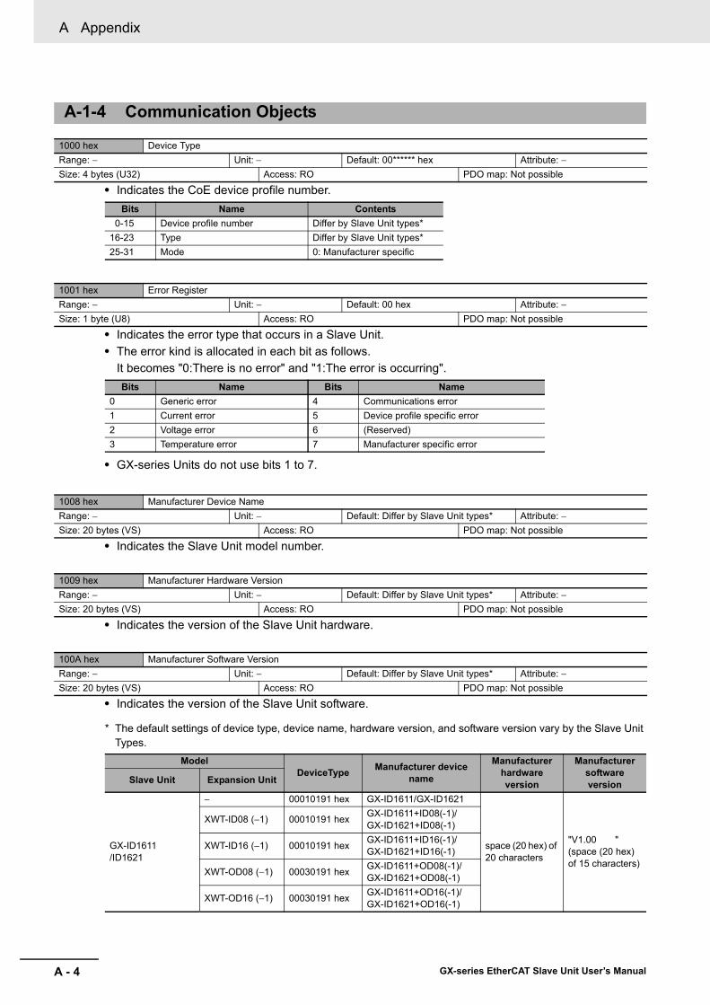
A Appendix
A - 4 GX-series EtherCAT Slave Unit User’s Manual
• Indicates the CoE device profile number.
• Indicates the error type that occurs in a Slave Unit.• The error kind is allocated in each bit as follows.
It becomes "0:There is no error" and "1:The error is occurring".
• GX-series Units do not use bits 1 to 7.
• Indicates the Slave Unit model number.
• Indicates the version of the Slave Unit hardware.
• Indicates the version of the Slave Unit software.
* The default settings of device type, device name, hardware version, and software version vary by the Slave Unit Types.
A-1-4 Communication Objects
1000 hex Device TypeRange: − Unit: − Default: 00****** hex Attribute: −Size: 4 bytes (U32) Access: RO PDO map: Not possible
Bits Name Contents 0-15 Device profile number Differ by Slave Unit types*16-23 Type Differ by Slave Unit types*25-31 Mode 0: Manufacturer specific
1001 hex Error RegisterRange: − Unit: − Default: 00 hex Attribute: −Size: 1 byte (U8) Access: RO PDO map: Not possible
Bits Name Bits Name0 Generic error 4 Communications error1 Current error 5 Device profile specific error2 Voltage error 6 (Reserved)3 Temperature error 7 Manufacturer specific error
1008 hex Manufacturer Device NameRange: − Unit: − Default: Differ by Slave Unit types* Attribute: −Size: 20 bytes (VS) Access: RO PDO map: Not possible
1009 hex Manufacturer Hardware VersionRange: − Unit: − Default: Differ by Slave Unit types* Attribute: −Size: 20 bytes (VS) Access: RO PDO map: Not possible
100A hex Manufacturer Software VersionRange: − Unit: − Default: Differ by Slave Unit types* Attribute: −Size: 20 bytes (VS) Access: RO PDO map: Not possible
ModelDeviceType Manufacturer device
name
Manufacturer hardware version
Manufacturer software versionSlave Unit Expansion Unit
GX-ID1611/ID1621
− 00010191 hex GX-ID1611/GX-ID1621
space (20 hex) of 20 characters
"V1.00 "(space (20 hex) of 15 characters)
XWT-ID08 (−1) 00010191 hex GX-ID1611+ID08(-1)/GX-ID1621+ID08(-1)
XWT-ID16 (−1) 00010191 hex GX-ID1611+ID16(-1)/GX-ID1621+ID16(-1)
XWT-OD08 (−1) 00030191 hex GX-ID1611+OD08(-1)/GX-ID1621+OD08(-1)
XWT-OD16 (−1) 00030191 hex GX-ID1611+OD16(-1)/GX-ID1621+OD16(-1)

A - 5
A Appendix
GX-series EtherCAT Slave Unit User’s Manual
A-1 O
bject Dictionary
A
A-1-4 C
omm
unication Objects
GX-OD1611/OD1621
− 00020191 hex GX-OD1611/GX-OD1621
space (20 hex) of 20 characters
"V1.00 "(space (20 hex) of 15 characters)
XWT-ID08 (−1) 00030191 hex GX-OD1611+ID08(-1)/GX-OD1621+ID08(-1)
XWT-ID16 (−1) 00030191 hex GX-OD1611+ID16(-1)/GX-OD1621+ID16(-1)
XWT-OD08 (−1) 00020191 hex GX-OD1611+OD08(-1)/GX-OD1621+OD08(-1)
XWT-OD16 (−1) 00020191 hex GX-OD1611+OD16(-1)/GX-OD1621+OD16(-1)
GX-OC1601
− 00020191 hex GX-OC1601XWT-ID08 (−1) 00030191 hex GX-OC1601+ID08(-1)XWT-ID16 (−1) 00030191 hex GX-OC1601+ID16(-1)XWT-OD08 (−1) 00020191 hex GX-OC1601+OD08(-1)XWT-OD16 (−1) 00020191 hex GX-OC1601+OD16(-1)
GX-MD1611/MD1621 − 00030191 hex
"GX-MD1611 "/"GX-MD1621 "(space (20 hex) of 11 characters)
GX-ID1612/ID1622 − 00010191 hex
"GX-ID1612 "/"GX-ID1622 "(space (20 hex) of 11 characters)
GX-OD1612/OD1622 - 00020191 hex
"GX-OD1612 "/"GX-OD1622 "(space (20 hex) of 11 characters)
GX-MD1612/MD1622 − 00030191 hex
"GX-MD1612 "/"GX-MD1622 "(space (20 hex) of 11 characters)
GX-ID1618/ID1628 − 00010191 hex
"GX-ID1618 "/"GX-ID1628 "(space (20 hex) of 11 characters)
GX-OD1618/OD1628 − 00020191 hex
"GX-OD1618 "/"GX-OD1628 "(space (20 hex) of 11 characters)
GX-MD1618/MD1628 − 00030191 hex
"GX-MD1618 "/"GX-MD1628 "(space (20 hex) of 11 characters)
GX-ID3218/ID3228 − 00010191 hex
"GX-ID3218 "/"GX-ID3228 "(space (20 hex) of 11 characters)
GX-OD3218/OD3228 − 00020191 hex
"GX-OD3218 "/"GX-OD3228 "(space (20 hex) of 11 characters)
GX-MD3218/MD3228 − 00030191 hex
"GX-MD3218 "/"GX-MD3228 "(space (20 hex) of 11 characters)
GX-AD0471 − 00040191 hex"GX-AD0471 "(space (20 hex) of 11 characters)
GX-DA0271 − 00080191 hex"GX-DA0271 "(space (20 hex) of 11 characters)
ModelDeviceType Manufacturer device
name
Manufacturer hardware version
Manufacturer software versionSlave Unit Expansion Unit
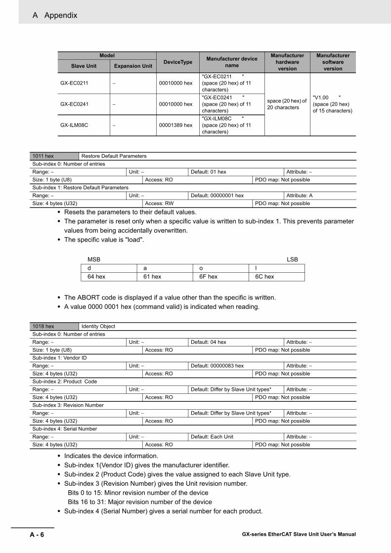
A Appendix
A - 6 GX-series EtherCAT Slave Unit User’s Manual
• Resets the parameters to their default values.• The parameter is reset only when a specific value is written to sub-index 1. This prevents parameter
values from being accidentally overwritten.• The specific value is "load".
• The ABORT code is displayed if a value other than the specific is written. • A value 0000 0001 hex (command valid) is indicated when reading.
• Indicates the device information.• Sub-index 1(Vendor ID) gives the manufacturer identifier. • Sub-index 2 (Product Code) gives the value assigned to each Slave Unit type.• Sub-index 3 (Revision Number) gives the Unit revision number.
Bits 0 to 15: Minor revision number of the device Bits 16 to 31: Major revision number of the device
• Sub-index 4 (Serial Number) gives a serial number for each product.
GX-EC0211 − 00010000 hex"GX-EC0211 "(space (20 hex) of 11 characters)
space (20 hex) of 20 characters
"V1.00 "(space (20 hex) of 15 characters)
GX-EC0241 − 00010000 hex"GX-EC0241 "(space (20 hex) of 11 characters)
GX-ILM08C − 00001389 hex"GX-ILM08C "(space (20 hex) of 11 characters)
1011 hex Restore Default ParametersSub-index 0: Number of entriesRange: − Unit: − Default: 01 hex Attribute: −Size: 1 byte (U8) Access: RO PDO map: Not possibleSub-index 1: Restore Default ParametersRange: − Unit: − Default: 00000001 hex Attribute: ASize: 4 bytes (U32) Access: RW PDO map: Not possible
MSB LSBd a o l64 hex 61 hex 6F hex 6C hex
1018 hex Identity ObjectSub-index 0: Number of entriesRange: − Unit: − Default: 04 hex Attribute: −Size: 1 byte (U8) Access: RO PDO map: Not possibleSub-index 1: Vendor IDRange: − Unit: − Default: 00000083 hex Attribute: −Size: 4 bytes (U32) Access: RO PDO map: Not possibleSub-index 2: Product CodeRange: − Unit: − Default: Differ by Slave Unit types* Attribute: −Size: 4 bytes (U32) Access: RO PDO map: Not possibleSub-index 3: Revision NumberRange: − Unit: − Default: Differ by Slave Unit types* Attribute: −Size: 4 bytes (U32) Access: RO PDO map: Not possibleSub-index 4: Serial NumberRange: − Unit: − Default: Each Unit Attribute: −Size: 4 bytes (U32) Access: RO PDO map: Not possible
ModelDeviceType Manufacturer device
name
Manufacturer hardware version
Manufacturer software versionSlave Unit Expansion Unit
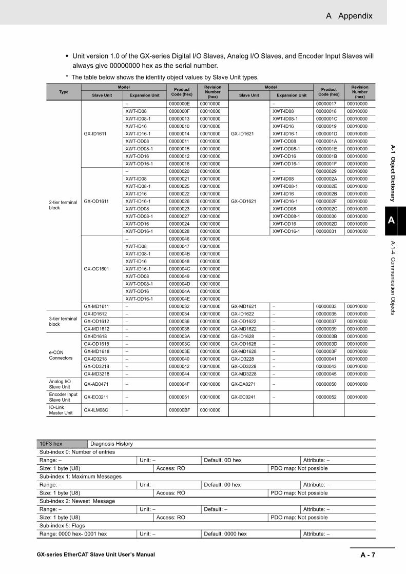
A - 7
A Appendix
GX-series EtherCAT Slave Unit User’s Manual
A-1 O
bject Dictionary
A
A-1-4 C
omm
unication Objects
• Unit version 1.0 of the GX-series Digital I/O Slaves, Analog I/O Slaves, and Encoder Input Slaves will always give 00000000 hex as the serial number.
* The table below shows the identity object values by Slave Unit types.
TypeModel Product
Code (hex)
Revision Number
(hex)
Model Product Code (hex)
Revision Number
(hex)Slave Unit Expansion Unit Slave Unit Expansion Unit
2-tier terminal block
GX-ID1611
− 0000000E 00010000
GX-ID1621
− 00000017 00010000XWT-ID08 0000000F 00010000 XWT-ID08 00000018 00010000XWT-ID08-1 00000013 00010000 XWT-ID08-1 0000001C 00010000XWT-ID16 00000010 00010000 XWT-ID16 00000019 00010000XWT-ID16-1 00000014 00010000 XWT-ID16-1 0000001D 00010000XWT-OD08 00000011 00010000 XWT-OD08 0000001A 00010000XWT-OD08-1 00000015 00010000 XWT-OD08-1 0000001E 00010000XWT-OD16 00000012 00010000 XWT-OD16 0000001B 00010000XWT-OD16-1 00000016 00010000 XWT-OD16-1 0000001F 00010000
GX-OD1611
− 00000020 00010000
GX-OD1621
− 00000029 00010000XWT-ID08 00000021 00010000 XWT-ID08 0000002A 00010000XWT-ID08-1 00000025 00010000 XWT-ID08-1 0000002E 00010000XWT-ID16 00000022 00010000 XWT-ID16 0000002B 00010000XWT-ID16-1 00000026 00010000 XWT-ID16-1 0000002F 00010000XWT-OD08 00000023 00010000 XWT-OD08 0000002C 00010000XWT-OD08-1 00000027 00010000 XWT-OD08-1 00000030 00010000XWT-OD16 00000024 00010000 XWT-OD16 0000002D 00010000XWT-OD16-1 00000028 00010000 XWT-OD16-1 00000031 00010000
GX-OC1601
− 00000046 00010000XWT-ID08 00000047 00010000XWT-ID08-1 0000004B 00010000XWT-ID16 00000048 00010000XWT-ID16-1 0000004C 00010000XWT-OD08 00000049 00010000XWT-OD08-1 0000004D 00010000XWT-OD16 0000004A 00010000XWT-OD16-1 0000004E 00010000
GX-MD1611 − 00000032 00010000 GX-MD1621 − 00000033 00010000
3-tier terminal block
GX-ID1612 − 00000034 00010000 GX-ID1622 − 00000035 00010000GX-OD1612 − 00000036 00010000 GX-OD1622 − 00000037 00010000GX-MD1612 − 00000038 00010000 GX-MD1622 − 00000039 00010000
e-CONConnectors
GX-ID1618 − 0000003A 00010000 GX-ID1628 − 0000003B 00010000GX-OD1618 − 0000003C 00010000 GX-OD1628 − 0000003D 00010000GX-MD1618 − 0000003E 00010000 GX-MD1628 − 0000003F 00010000GX-ID3218 − 00000040 00010000 GX-ID3228 − 00000041 00010000GX-OD3218 − 00000042 00010000 GX-OD3228 − 00000043 00010000GX-MD3218 − 00000044 00010000 GX-MD3228 − 00000045 00010000
Analog I/OSlave Unit GX-AD0471 − 0000004F 00010000 GX-DA0271 − 00000050 00010000
Encoder Input Slave Unit GX-EC0211 − 00000051 00010000 GX-EC0241 − 00000052 00010000
IO-Link Master Unit GX-ILM08C − 000000BF 00010000
10F3 hex Diagnosis HistorySub-index 0: Number of entriesRange: − Unit: − Default: 0D hex Attribute: −Size: 1 byte (U8) Access: RO PDO map: Not possibleSub-index 1: Maximum MessagesRange: − Unit: − Default: 00 hex Attribute: −Size: 1 byte (U8) Access: RO PDO map: Not possibleSub-index 2: Newest MessageRange: − Unit: − Default: − Attribute: −Size: 1 byte (U8) Access: RO PDO map: Not possibleSub-index 5: FlagsRange: 0000 hex- 0001 hex Unit: − Default: 0000 hex Attribute: −

A Appendix
A - 8 GX-series EtherCAT Slave Unit User’s Manual
• This object indicates up to 8 diagnosis histories. It also sets whether to notify emergency messages or not.
• Sub-index 1 (Maximum Messages) gives the number of error messages. • Sub-index 2 (Newest Messages) gives the sub-index number the latest message in the diagnosis
history.• Sub-index 5 (Flags) is the control flag of diagnosis history. It specifies whether or not to notify error
messages via emergency messages. Setting 0001 hex means to notify. It is set to 0001 hex (Emergency notify) when power is turned ON. At startup, the setting is 0000 hex (no emergency notification).
• Sub-indexes 6 to 13 (Diagnosis messages 1 to 8) indicate the diagnosis history. From sub-index 6 (Diagnosis message 1) to sub-index 13 (Diagnosis message 8) are stored 8 errors. The 9th error and onward are stored from the sub-index 6 (Diagnosis message 1) again.
Indexes 1600 hex to 17FF hex are used for Receive PDO mapping, and indexes 1A00 hex to 1BFF hex are used for Transmit PDO mapping. Sub-indexes after sub-index 1 provide information about the application object being mapped.
The following indexes describes the specific objects by Slave Unit types.
• This object gives the mapping for an application that uses digital output functions.
Size: 2 bytes (U16) Access: RW PDO map: Not possibleSub-index 6 to 13: Diagnosis Message 1-8Range: − Unit: − Default: − Attribute: −Size: 23 bytes (VS) Access: RO PDO map: Not possible
A-1-5 PDO Mapping Object
31 16 15 8 7 0
IndexesSubIndexes
Bit length
MSB LSB
Bits 0 to 7 : Bit length of the mapped object.(For example, for 32 bits, 20 hex is given.)
Bits 8 to 15 : Sub-index of the mapped object.Bits 16 to 31 : Index of the mapped object.
Digital I/O Slave Unit
1700 hex 257th receive PDO MappingSub-index 0: Number of objectsRange: − Unit: − Default: Differ by Slave Unit types* Attribute: −Size: 1 byte (U8) Access: RO PDO map: Not possibleSub-index 1: 1st Output Object to be mappedRange: − Unit: − Default: Differ by Slave Unit types* Attribute: −Size: 4 bytes (U32) Access: RO PDO map: Not possible

A - 9
A Appendix
GX-series EtherCAT Slave Unit User’s Manual
A-1 O
bject Dictionary
A
A-1-5 P
DO
Mapping O
bject
1701 hex 258th receive PDO MappingSub-index 0: Number of objectsRange: − Unit: − Default: Differ by Slave Unit types* Attribute: −Size: 1 byte (U8) Access: RO PDO map: Not possibleSub-index 1: 1st Output Object to be mappedRange: − Unit: − Default: 32200101 hex Attribute: −Size: 1 byte (BOOL) Access: RO PDO map: Not possibleSub-index 2: 2nd Output Object to be mappedRange: − Unit: − Default: 32200201 hex Attribute: −Size: 1 byte (BOOL) Access: RO PDO map: Not possibleSub-index 3: 3rd Output Object to be mappedRange: − Unit: − Default: 32200301 hex Attribute: −Size: 1 byte (BOOL) Access: RO PDO map: Not possibleSub-index 4: 4th Output Object to be mappedRange: − Unit: − Default: 32200401 hex Attribute: −Size: 1 byte (BOOL) Access: RO PDO map: Not possibleSub-index 5: 5th Output Object to be mappedRange: − Unit: − Default: 32200501 hex Attribute: −Size: 1 byte (BOOL) Access: RO PDO map: Not possibleSub-index 6: 6th Output Object to be mappedRange: − Unit: − Default: 32200601 hex Attribute: −Size: 1 byte (BOOL) Access: RO PDO map: Not possibleSub-index 7: 7th Output Object to be mappedRange: − Unit: − Default: 32200701 hex Attribute: −Size: 1 byte (BOOL) Access: RO PDO map: Not possibleSub-index 8: 8th Output Object to be mappedRange: − Unit: − Default: 32200801 hex Attribute: −Size: 1 byte (BOOL) Access: RO PDO map: Not possibleSub-index 9: 9th Output Object to be mappedRange: − Unit: − Default: 32200901 hex Attribute: −Size: 1 byte (BOOL) Access: RO PDO map: Not possibleSub-index 10: 10th Output Object to be mappedRange: − Unit: − Default: 32200A01 hex Attribute: −Size: 1 byte (BOOL) Access: RO PDO map: Not possibleSub-index 11: 11th Output Object to be mappedRange: − Unit: − Default: 32200B01 hex Attribute: −Size: 1 byte (BOOL) Access: RO PDO map: Not possibleSub-index 12: 12th Output Object to be mappedRange: − Unit: − Default: 32200C01 hex Attribute: −Size: 1 byte (BOOL) Access: RO PDO map: Not possibleSub-index 13: 13th Output Object to be mappedRange: − Unit: − Default: 32200D01 hex Attribute: −Size: 1 byte (BOOL) Access: RO PDO map: Not possibleSub-index 14: 14th Output Object to be mappedRange: − Unit: − Default: 32200E01 hex Attribute: −Size: 1 byte (BOOL) Access: RO PDO map: Not possibleSub-index 15: 15th Output Object to be mappedRange: − Unit: − Default: 32200F01 hex Attribute: −Size: 1 byte (BOOL) Access: RO PDO map: Not possibleSub-index 16: 16th Output Object to be mappedRange: − Unit: − Default: 32201001 hex Attribute: −Size: 1 byte (BOOL) Access: RO PDO map: Not possibleSub-index 17: 17th Output Object to be mappedRange: − Unit: − Default: 32201101 hex Attribute: −Size: 1 byte (BOOL) Access: RO PDO map: Not possibleSub-index 18: 18th Output Object to be mappedRange: − Unit: − Default: 32201201 hex Attribute: −Size: 1 byte (BOOL) Access: RO PDO map: Not possible
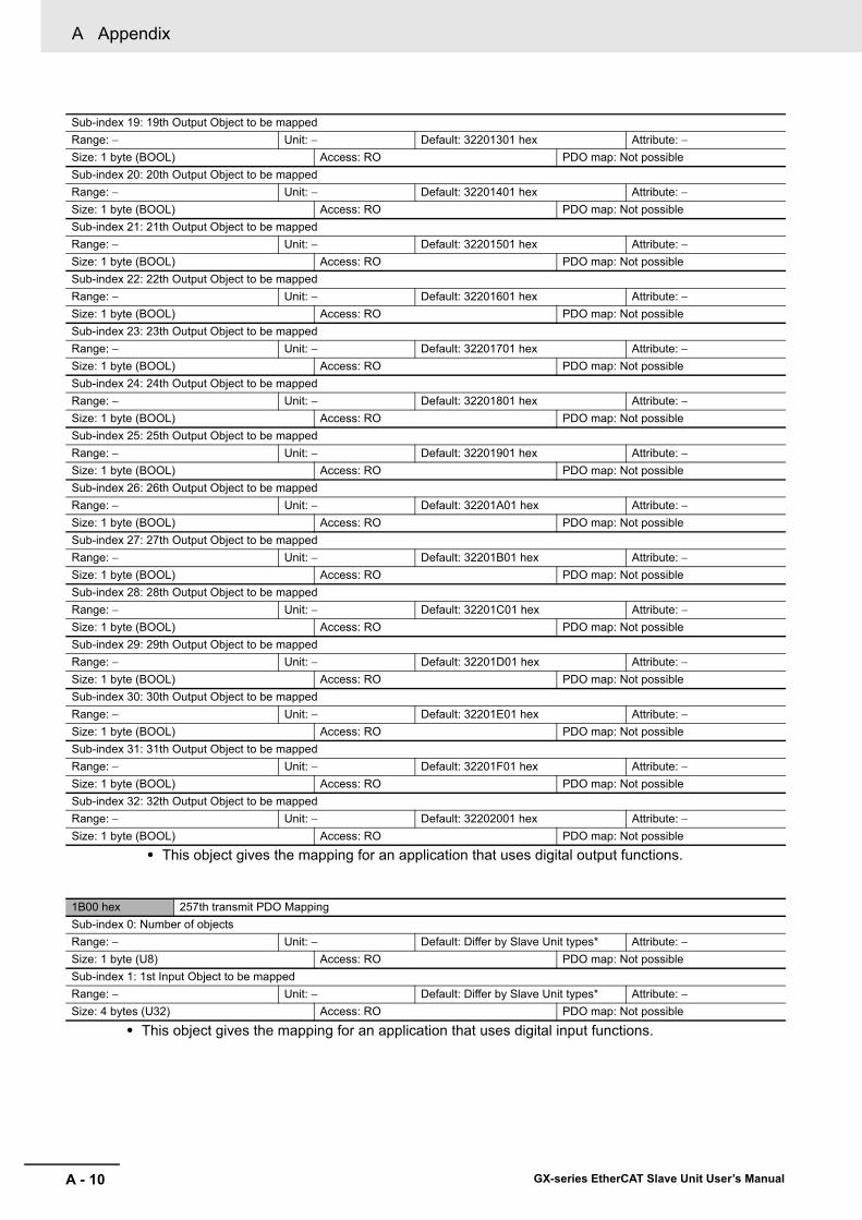
A Appendix
A - 10 GX-series EtherCAT Slave Unit User’s Manual
• This object gives the mapping for an application that uses digital output functions.
• This object gives the mapping for an application that uses digital input functions.
Sub-index 19: 19th Output Object to be mappedRange: − Unit: − Default: 32201301 hex Attribute: −Size: 1 byte (BOOL) Access: RO PDO map: Not possibleSub-index 20: 20th Output Object to be mappedRange: − Unit: − Default: 32201401 hex Attribute: −Size: 1 byte (BOOL) Access: RO PDO map: Not possibleSub-index 21: 21th Output Object to be mappedRange: − Unit: − Default: 32201501 hex Attribute: −Size: 1 byte (BOOL) Access: RO PDO map: Not possibleSub-index 22: 22th Output Object to be mappedRange: − Unit: − Default: 32201601 hex Attribute: −Size: 1 byte (BOOL) Access: RO PDO map: Not possibleSub-index 23: 23th Output Object to be mappedRange: − Unit: − Default: 32201701 hex Attribute: −Size: 1 byte (BOOL) Access: RO PDO map: Not possibleSub-index 24: 24th Output Object to be mappedRange: − Unit: − Default: 32201801 hex Attribute: −Size: 1 byte (BOOL) Access: RO PDO map: Not possibleSub-index 25: 25th Output Object to be mappedRange: − Unit: − Default: 32201901 hex Attribute: −Size: 1 byte (BOOL) Access: RO PDO map: Not possibleSub-index 26: 26th Output Object to be mappedRange: − Unit: − Default: 32201A01 hex Attribute: −Size: 1 byte (BOOL) Access: RO PDO map: Not possibleSub-index 27: 27th Output Object to be mappedRange: − Unit: − Default: 32201B01 hex Attribute: −Size: 1 byte (BOOL) Access: RO PDO map: Not possibleSub-index 28: 28th Output Object to be mappedRange: − Unit: − Default: 32201C01 hex Attribute: −Size: 1 byte (BOOL) Access: RO PDO map: Not possibleSub-index 29: 29th Output Object to be mappedRange: − Unit: − Default: 32201D01 hex Attribute: −Size: 1 byte (BOOL) Access: RO PDO map: Not possibleSub-index 30: 30th Output Object to be mappedRange: − Unit: − Default: 32201E01 hex Attribute: −Size: 1 byte (BOOL) Access: RO PDO map: Not possibleSub-index 31: 31th Output Object to be mappedRange: − Unit: − Default: 32201F01 hex Attribute: −Size: 1 byte (BOOL) Access: RO PDO map: Not possibleSub-index 32: 32th Output Object to be mappedRange: − Unit: − Default: 32202001 hex Attribute: −Size: 1 byte (BOOL) Access: RO PDO map: Not possible
1B00 hex 257th transmit PDO MappingSub-index 0: Number of objectsRange: − Unit: − Default: Differ by Slave Unit types* Attribute: −Size: 1 byte (U8) Access: RO PDO map: Not possibleSub-index 1: 1st Input Object to be mappedRange: − Unit: − Default: Differ by Slave Unit types* Attribute: −Size: 4 bytes (U32) Access: RO PDO map: Not possible

A - 11
A Appendix
GX-series EtherCAT Slave Unit User’s Manual
A-1 O
bject Dictionary
A
A-1-5 P
DO
Mapping O
bject
* The default settings of the 257th transmit PDO Mapping and the 257th receive PDO Mapping are given below.
TypeModel 257th Receive PDO Mapping 257th Transmit PDO Mapping
Slave Unit Expansion Unit Number of objects 1st object Number of
objects 1st object
2-tier terminal block
GX-ID1611/ID1621
− − − 01 hex 61000110 hexXWT-ID08 (−1) − − 01 hex 61200120 hexXWT-ID16 (−1) − − 01 hex 61200120 hexXWT-OD08 (−1) 01 hex 63000110 hex 01 hex 61000110 hexXWT-OD16 (−1) 01 hex 63000110 hex 01 hex 61000110 hex
GX-OD1611/OD1621
− 01 hex 63000110 hex − −XWT-ID08 (−1) 01 hex 63000110 hex 01 hex 61000110 hexXWT-ID16 (−1) 01 hex 63000110 hex 01 hex 61000110 hexXWT-OD08 (−1) 01 hex 63200120 hex − −XWT-OD16 (−1) 01 hex 63200120 hex − −
GX-OC1601
− 01 hex 63000110 hex − −XWT-ID08 (−1) 01 hex 63000110 hex 01 hex 61000110 hexXWT-ID16 (−1) 01 hex 63000110 hex 01 hex 61000110 hexXWT-OD08 (−1) 01 hex 63200120 hex − −XWT-OD16 (−1) 01 hex 63200120 hex − −
GX-MD1611/MD1621 − 01 hex 63000110 hex 01 hex 61000110 hex
3-tier terminal block
GX-ID1612/ID1622 − − − 01 hex 61000110 hexGX-OD1612/OD1622 − 01 hex 63000110 hex − −GX-MD1612/MD1622 − 01 hex 63000110 hex 01 hex 61000110 hex
e-CONConnectors
GX-ID1618/ID1628 − − − 01 hex 61000110 hexGX-OD1618/OD1628 − 01 hex 63000110 hex − −GX-MD1618/MD1628 − 01 hex 63000110 hex 01 hex 61000110 hexGX-ID3218/ID3228 − − − 01 hex 61200120 hexGX-OD3218/OD3228 − 01 hex 63200120 hex − −GX-MD3218/MD3228 − 01 hex 63000110 hex 01 hex 61000110 hex

A Appendix
A - 12 GX-series EtherCAT Slave Unit User’s Manual
1B01 hex 258th transmit PDO MappingSub-index 0: Number of objectsRange: − Unit: − Default: Differ by Slave Unit types* Attribute: −Size: 1 byte (U8) Access: RO PDO map: Not possibleSub-index 1: 1st Input Object to be mappedRange: − Unit: − Default: 30200101 hex Attribute: −Size: 1 byte (BOOL) Access: RO PDO map: Not possibleSub-index 2: 2nd Input Object to be mappedRange: − Unit: − Default: 30200201 hex Attribute: −Size: 1 byte (BOOL) Access: RO PDO map: Not possibleSub-index 3: 3rd Input Object to be mappedRange: − Unit: − Default: 30200301 hex Attribute: −Size: 1 byte (BOOL) Access: RO PDO map: Not possibleSub-index 4: 4th Input Object to be mappedRange: − Unit: − Default: 30200401 hex Attribute: −Size: 1 byte (BOOL) Access: RO PDO map: Not possibleSub-index 5: 5th Input Object to be mappedRange: − Unit: − Default: 30200501 hex Attribute: −Size: 1 byte (BOOL) Access: RO PDO map: Not possibleSub-index 6: 6th Input Object to be mappedRange: − Unit: − Default: 30200601 hex Attribute: −Size: 1 byte (BOOL) Access: RO PDO map: Not possibleSub-index 7: 7th Input Object to be mappedRange: − Unit: − Default: 30200701 hex Attribute: −Size: 1 byte (BOOL) Access: RO PDO map: Not possibleSub-index 8: 8th Input Object to be mappedRange: − Unit: − Default: 30200801 hex Attribute: −Size: 1 byte (BOOL) Access: RO PDO map: Not possibleSub-index 9: 9th Input Object to be mappedRange: − Unit: − Default: 30200901 hex Attribute: −Size: 1 byte (BOOL) Access: RO PDO map: Not possibleSub-index 10: 10th Input Object to be mappedRange: − Unit: − Default: 30200A01 hex Attribute: −Size: 1 byte (BOOL) Access: RO PDO map: Not possibleSub-index 11: 11th Input Object to be mappedRange: − Unit: − Default: 30200B01 hex Attribute: −Size: 1 byte (BOOL) Access: RO PDO map: Not possibleSub-index 12: 12th Input Object to be mappedRange: − Unit: − Default: 30200C01 hex Attribute: −Size: 1 byte (BOOL) Access: RO PDO map: Not possibleSub-index 13: 13th Input Object to be mappedRange: − Unit: − Default: 30200D01 hex Attribute: −Size: 1 byte (BOOL) Access: RO PDO map: Not possibleSub-index 14: 14th Input Object to be mappedRange: − Unit: − Default: 30200E01 hex Attribute: −Size: 1 byte (BOOL) Access: RO PDO map: Not possibleSub-index 15: 15th Input Object to be mappedRange: − Unit: − Default: 30200F01 hex Attribute: −Size: 1 byte (BOOL) Access: RO PDO map: Not possibleSub-index 16: 16th Input Object to be mappedRange: − Unit: − Default: 30201001 hex Attribute: −Size: 1 byte (BOOL) Access: RO PDO map: Not possibleSub-index 17: 17th Input Object to be mappedRange: − Unit: − Default: 30201101 hex Attribute: −Size: 1 byte (BOOL) Access: RO PDO map: Not possibleSub-index 18: 18th Input Object to be mappedRange: − Unit: − Default: 30201201 hex Attribute: −Size: 1 byte (BOOL) Access: RO PDO map: Not possible

A - 13
A Appendix
GX-series EtherCAT Slave Unit User’s Manual
A-1 O
bject Dictionary
A
A-1-5 P
DO
Mapping O
bject
• This object gives the mapping for an application that uses digital input functions.
Sub-index 19: 19th Input Object to be mappedRange: − Unit: − Default: 30201301 hex Attribute: −Size: 1 byte (BOOL) Access: RO PDO map: Not possibleSub-index 20: 20th Input Object to be mappedRange: − Unit: − Default: 30201401 hex Attribute: −Size: 1 byte (BOOL) Access: RO PDO map: Not possibleSub-index 21: 21th Input Object to be mappedRange: − Unit: − Default: 30201501 hex Attribute: −Size: 1 byte (BOOL) Access: RO PDO map: Not possibleSub-index 22: 22th Input Object to be mappedRange: − Unit: − Default: 30201601 hex Attribute: −Size: 1 byte (BOOL) Access: RO PDO map: Not possibleSub-index 23: 23th Input Object to be mappedRange: − Unit: − Default: 30201701 hex Attribute: −Size: 1 byte (BOOL) Access: RO PDO map: Not possibleSub-index 24: 24th Input Object to be mappedRange: − Unit: − Default: 30201801 hex Attribute: −Size: 1 byte (BOOL) Access: RO PDO map: Not possibleSub-index 25: 25th Input Object to be mappedRange: − Unit: − Default: 30201901 hex Attribute: −Size: 1 byte (BOOL) Access: RO PDO map: Not possibleSub-index 26: 26th Input Object to be mappedRange: − Unit: − Default: 30201A01 hex Attribute: −Size: 1 byte (BOOL) Access: RO PDO map: Not possibleSub-index 27: 27th Input Object to be mappedRange: − Unit: − Default: 30201B01 hex Attribute: −Size: 1 byte (BOOL) Access: RO PDO map: Not possibleSub-index 28: 28th Input Object to be mappedRange: − Unit: − Default: 30201C01 hex Attribute: −Size: 1 byte (BOOL) Access: RO PDO map: Not possibleSub-index 29: 29th Input Object to be mappedRange: − Unit: − Default: 30201D01 hex Attribute: −Size: 1 byte (BOOL) Access: RO PDO map: Not possibleSub-index 30: 30th Input Object to be mappedRange: − Unit: − Default: 30201E01 hex Attribute: −Size: 1 byte (BOOL) Access: RO PDO map: Not possibleSub-index 31: 31th Input Object to be mappedRange: − Unit: − Default: 30201F01 hex Attribute: −Size: 1 byte (BOOL) Access: RO PDO map: Not possibleSub-index 32: 32th Input Object to be mappedRange: − Unit: − Default: 30202001 hex Attribute: −Size: 1 byte (BOOL) Access: RO PDO map: Not possible
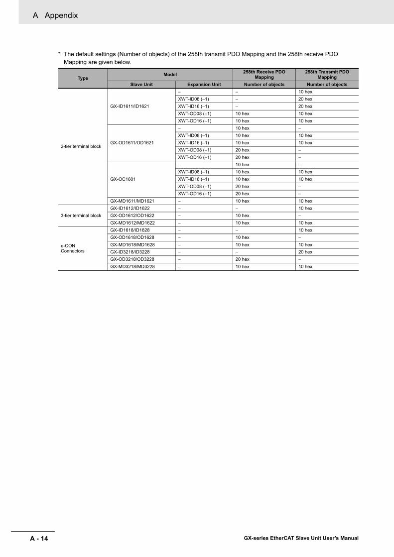
A Appendix
A - 14 GX-series EtherCAT Slave Unit User’s Manual
* The default settings (Number of objects) of the 258th transmit PDO Mapping and the 258th receive PDO Mapping are given below.
TypeModel 258th Receive PDO
Mapping258th Transmit PDO
MappingSlave Unit Expansion Unit Number of objects Number of objects
2-tier terminal block
GX-ID1611/ID1621
− − 10 hexXWT-ID08 (−1) − 20 hexXWT-ID16 (−1) − 20 hexXWT-OD08 (−1) 10 hex 10 hexXWT-OD16 (−1) 10 hex 10 hex
GX-OD1611/OD1621
− 10 hex −XWT-ID08 (−1) 10 hex 10 hexXWT-ID16 (−1) 10 hex 10 hexXWT-OD08 (−1) 20 hex −XWT-OD16 (−1) 20 hex −
GX-OC1601
− 10 hex −XWT-ID08 (−1) 10 hex 10 hexXWT-ID16 (−1) 10 hex 10 hexXWT-OD08 (−1) 20 hex −XWT-OD16 (−1) 20 hex −
GX-MD1611/MD1621 − 10 hex 10 hex
3-tier terminal blockGX-ID1612/ID1622 − − 10 hexGX-OD1612/OD1622 − 10 hex −GX-MD1612/MD1622 − 10 hex 10 hex
e-CONConnectors
GX-ID1618/ID1628 − − 10 hexGX-OD1618/OD1628 − 10 hex −GX-MD1618/MD1628 − 10 hex 10 hexGX-ID3218/ID3228 − − 20 hexGX-OD3218/OD3228 − 20 hex −GX-MD3218/MD3228 − 10 hex 10 hex

A - 15
A Appendix
GX-series EtherCAT Slave Unit User’s Manual
A-1 O
bject Dictionary
A
A-1-5 P
DO
Mapping O
bject
• This object gives the mapping for an analog output application. It is mapped only to Analog Output Slave Units.
• This object gives the mapping for an analog input application. It is mapped only to Analog Input Slave Units.
Analog I/O Slave Unit
1700 hex 257th receive PDO MappingSub-index 0: Number of objectsRange: − Unit: − Default: 02 hex Attribute: −Size: 1 byte (U8) Access: RO PDO map: Not possibleSub-index 1: 1st Output Object to be mappedRange: − Unit: − Default: 64110110 hex Attribute: −Size: 4 bytes (U32) Access: RO PDO map: Not possibleSub-index 2: 2nd Output Object to be mappedRange: − Unit: − Default: 64110210 hex Attribute: −Size: 4 bytes (U32) Access: RO PDO map: Not possible
1B00 hex 257th transmit PDO MappingSub-index 0: Number of objectsRange: − Unit: − Default: 04 hex Attribute: −Size: 1 byte (U8) Access: RO PDO map: Not possibleSub-index 1: 1st Input Object to be mappedRange:− Unit: − Default: 64010110 hex Attribute: −Size: 4 bytes (U32) Access: RO PDO map: Not possibleSub-index 2: 2nd Input Object to be mappedRange: − Unit: − Default: 64010210 hex Attribute: −Size: 4 bytes (U32) Access: RO PDO map: Not possibleSub-index 3: 3rd Input Object to be mappedRange: − Unit: − Default: 64010310 hex Attribute: −Size: 4 bytes (U32) Access: RO PDO map: Not possibleSub-index 4: 4th Input Object to be mappedRange: − Unit: − Default: 64010410 hex Attribute: −Size: 4 bytes (U32) Access: RO PDO map: Not possible
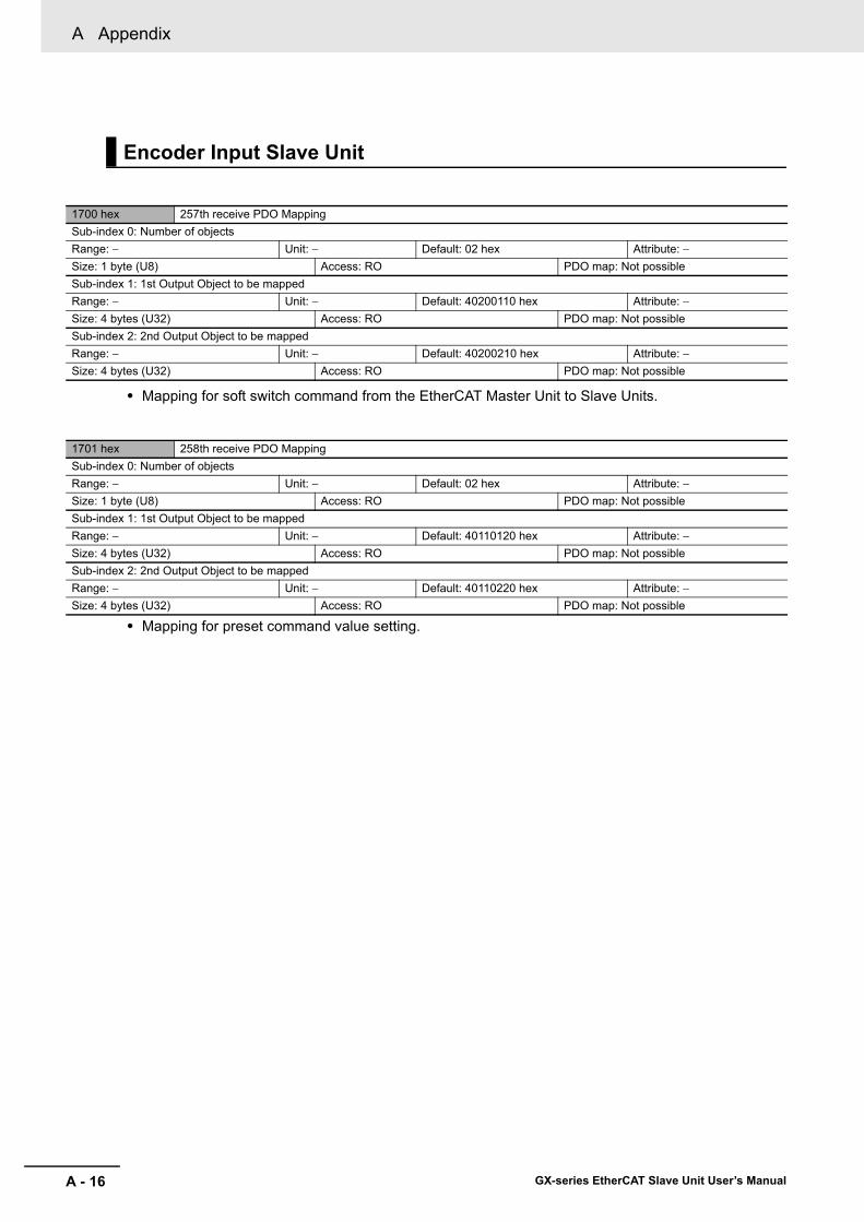
A Appendix
A - 16 GX-series EtherCAT Slave Unit User’s Manual
• Mapping for soft switch command from the EtherCAT Master Unit to Slave Units.
• Mapping for preset command value setting.
Encoder Input Slave Unit
1700 hex 257th receive PDO MappingSub-index 0: Number of objectsRange: − Unit: − Default: 02 hex Attribute: −Size: 1 byte (U8) Access: RO PDO map: Not possibleSub-index 1: 1st Output Object to be mappedRange: − Unit: − Default: 40200110 hex Attribute: −Size: 4 bytes (U32) Access: RO PDO map: Not possibleSub-index 2: 2nd Output Object to be mappedRange: − Unit: − Default: 40200210 hex Attribute: −Size: 4 bytes (U32) Access: RO PDO map: Not possible
1701 hex 258th receive PDO MappingSub-index 0: Number of objectsRange: − Unit: − Default: 02 hex Attribute: −Size: 1 byte (U8) Access: RO PDO map: Not possibleSub-index 1: 1st Output Object to be mappedRange: − Unit: − Default: 40110120 hex Attribute: −Size: 4 bytes (U32) Access: RO PDO map: Not possibleSub-index 2: 2nd Output Object to be mappedRange: − Unit: − Default: 40110220 hex Attribute: −Size: 4 bytes (U32) Access: RO PDO map: Not possible

A - 17
A Appendix
GX-series EtherCAT Slave Unit User’s Manual
A-1 O
bject Dictionary
A
A-1-5 P
DO
Mapping O
bject
1702 hex 259th receive PDO MappingSub-index 0: Number of objectsRange: − Unit: − Default: 20 hex Attribute: −Size: 1 byte (U8) Access: RO PDO map: Not possibleSub-index 1: 1st Output Object to be mappedRange: − Unit: − Default: 40210101 hex Attribute: −Size: 1 byte (BOOL) Access: RO PDO map: Not possibleSub-index 2: 2nd Output Object to be mappedRange: − Unit: − Default: 40210201 hex Attribute: −Size: 1 byte (BOOL) Access: RO PDO map: Not possibleSub-index 3: 3rd Output Object to be mappedRange: − Unit: − Default: 40210301 hex Attribute: −Size: 1 byte (BOOL) Access: RO PDO map: Not possibleSub-index 4: 4th Output Object to be mappedRange: − Unit: − Default: 40210401 hex Attribute: −Size: 1 byte (BOOL) Access: RO PDO map: Not possibleSub-index 5: 5th Output Object to be mappedRange: − Unit: − Default: 40210501 hex Attribute: −Size: 1 byte (BOOL) Access: RO PDO map: Not possibleSub-index 6: 6th Output Object to be mappedRange: − Unit: − Default: 40210601 hex Attribute: −Size: 1 byte (BOOL) Access: RO PDO map: Not possibleSub-index 7: 7th Output Object to be mappedRange: − Unit: − Default: 40210701 hex Attribute: −Size: 1 byte (BOOL) Access: RO PDO map: Not possibleSub-index 8: 8th Output Object to be mappedRange: − Unit: − Default: 40210801 hex Attribute: −Size: 1 byte (BOOL) Access: RO PDO map: Not possibleSub-index 9: 9th Output Object to be mappedRange: − Unit: − Default: 40210901 hex Attribute: −Size: 1 byte (BOOL) Access: RO PDO map: Not possibleSub-index 10: 10th Output Object to be mappedRange: − Unit: − Default: 40210A01 hex Attribute: −Size: 1 byte (BOOL) Access: RO PDO map: Not possibleSub-index 11: 11th Output Object to be mappedRange: − Unit: − Default: 40210B01 hex Attribute: −Size: 1 byte (BOOL) Access: RO PDO map: Not possibleSub-index 12: 12th Output Object to be mappedRange: − Unit: − Default: 40210C01 hex Attribute: −Size: 1 byte (BOOL) Access: RO PDO map: Not possibleSub-index 13: 13th Output Object to be mappedRange: − Unit: − Default: 40210D01 hex Attribute: −Size: 1 byte (BOOL) Access: RO PDO map: Not possibleSub-index 14: 14th Output Object to be mappedRange: − Unit: − Default: 40210E01 hex Attribute: −Size: 1 byte (BOOL) Access: RO PDO map: Not possibleSub-index 15: 15th Output Object to be mappedRange: − Unit: − Default: 40210F01 hex Attribute: −Size: 1 byte (BOOL) Access: RO PDO map: Not possibleSub-index 16: 16th Output Object to be mappedRange: − Unit: − Default: 40211001 hex Attribute: −Size: 1 byte (BOOL) Access: RO PDO map: Not possibleSub-index 17: 17th Output Object to be mappedRange: − Unit: − Default: 40211101 hex Attribute: −Size: 1 byte (BOOL) Access: RO PDO map: Not possibleSub-index 18: 18th Output Object to be mappedRange: − Unit: − Default: 40211201 hex Attribute: −Size: 1 byte (BOOL) Access: RO PDO map: Not possible

A Appendix
A - 18 GX-series EtherCAT Slave Unit User’s Manual
• This mapping is for soft switch commands from the EtherCAT Master Unit to Slave Units.
• The mapping is for reading counter present values.
Sub-index 19: 19th Output Object to be mappedRange: − Unit: − Default: 40211301 hex Attribute: −Size: 1 byte (BOOL) Access: RO PDO map: Not possibleSub-index 20: 20th Output Object to be mappedRange: − Unit: − Default: 40211401 hex Attribute: −Size: 1 byte (BOOL) Access: RO PDO map: Not possibleSub-index 21: 21th Output Object to be mappedRange: − Unit: − Default: 40211501 hex Attribute: −Size: 1 byte (BOOL) Access: RO PDO map: Not possibleSub-index 22: 22th Output Object to be mappedRange: − Unit: − Default: 40211601 hex Attribute: −Size: 1 byte (BOOL) Access: RO PDO map: Not possibleSub-index 23: 23th Output Object to be mappedRange: − Unit: − Default: 40211701 hex Attribute: −Size: 1 byte (BOOL) Access: RO PDO map: Not possibleSub-index 24: 24th Output Object to be mappedRange: − Unit: − Default: 40211801 hex Attribute: −Size: 1 byte (BOOL) Access: RO PDO map: Not possibleSub-index 25: 25th Output Object to be mappedRange: − Unit: − Default: 40211901 hex Attribute: −Size: 1 byte (BOOL) Access: RO PDO map: Not possibleSub-index 26: 26th Output Object to be mappedRange: − Unit: − Default: 40211A01 hex Attribute: −Size: 1 byte (BOOL) Access: RO PDO map: Not possibleSub-index 27: 27th Output Object to be mappedRange: − Unit: − Default: 40211B01 hex Attribute: −Size: 1 byte (BOOL) Access: RO PDO map: Not possibleSub-index 28: 28th Output Object to be mappedRange: − Unit: − Default: 40211C01 hex Attribute: −Size: 1 byte (BOOL) Access: RO PDO map: Not possibleSub-index 29: 29th Output Object to be mappedRange: − Unit: − Default: 40211D01 hex Attribute: −Size: 1 byte (BOOL) Access: RO PDO map: Not possibleSub-index 30: 30th Output Object to be mappedRange: − Unit: − Default: 40211E01 hex Attribute: −Size: 1 byte (BOOL) Access: RO PDO map: Not possibleSub-index 31: 31th Output Object to be mappedRange: − Unit: − Default: 40211F01 hex Attribute: −Size: 1 byte (BOOL) Access: RO PDO map: Not possibleSub-index 32: 32th Output Object to be mappedRange: − Unit: − Default: 40212001 hex Attribute: −Size: 1 byte (BOOL) Access: RO PDO map: Not possible
1B00 hex 257th transmit PDO MappingSub-index 0: Number of objectsRange: − Unit: − Default: 02 hex Attribute: −Size: 1 byte (U8) Access: RO PDO map: Not possibleSub-index 1: 1st Input Object to be mappedRange:− Unit: − Default: 40100120 hex Attribute: −Size: 4 bytes (U32) Access: RO PDO map: Not possibleSub-index 2: 2nd Input Object to be mappedRange: − Unit: − Default: 40100220 hex Attribute: −Size: 4 bytes (U32) Access: RO PDO map: Not possible

A - 19
A Appendix
GX-series EtherCAT Slave Unit User’s Manual
A-1 O
bject Dictionary
A
A-1-5 P
DO
Mapping O
bject
• Mapping for preset command value setting.
• Mapping for latch value A/B reading.
• Mapping for status notification from a Slave Unit to the EtherCAT Master Unit.
1B01 hex 258th transmit PDO MappingSub-index 0: Number of objectsRange: − Unit: − Default: 02 hex Attribute: −Size: 1 byte (U8) Access: RO PDO map: Not possibleSub-index 1: 1st Input Object to be mappedRange:− Unit: − Default: 40120120 hex Attribute: −Size: 4 bytes (U32) Access: RO PDO map: Not possibleSub-index 2: 2nd Input Object to be mappedRange: − Unit: − Default: 40120220 hex Attribute: −Size: 4 bytes (U32) Access: RO PDO map: Not possible
1B02 hex 259th transmit PDO MappingSub-index 0: Number of objectsRange: − Unit: − Default: 02 hex Attribute: −Size: 1 byte (U8) Access: RO PDO map: Not possibleSub-index 1: 1st Input Object to be mappedRange:− Unit: − Default: 40130120 hex Attribute: −Size: 4 bytes (U32) Access: RO PDO map: Not possibleSub-index 2: 2nd Input Object to be mappedRange: − Unit: − Default: 40130220 hex Attribute: −Size: 4 bytes (U32) Access: RO PDO map: Not possible
1B03 hex 260th transmit PDO MappingSub-index 0: Number of objectsRange: − Unit: − Default: 02 hex Attribute: −Size: 1 byte (U8) Access: RO PDO map: Not possibleSub-index 1: 1st Input Object to be mappedRange:− Unit: − Default: 40300108 hex Attribute: −Size: 4 bytes (U32) Access: RO PDO map: Not possibleSub-index 2: 2nd Input Object to be mappedRange: − Unit: − Default: 40300208 hex Attribute: −Size: 4 bytes (U32) Access: RO PDO map: Not possible

A Appendix
A - 20 GX-series EtherCAT Slave Unit User’s Manual
• This mapping is for status notification from a Slave Unit to the EtherCAT Master Unit.
1B04 hex 261th transmit PDO MappingSub-index 0: Number of objectsRange: − Unit: − Default: 10 hex Attribute: −Size: 1 byte (U8) Access: RO PDO map: Not possibleSub-index 1: 1st Input Object to be mappedRange: − Unit: − Default: 40310101 hex Attribute: −Size: 1 byte (BOOL) Access: RO PDO map: Not possibleSub-index 2: 2nd Input Object to be mappedRange: − Unit: − Default: 40310201 hex Attribute: −Size: 1 byte (BOOL) Access: RO PDO map: Not possibleSub-index 3: 3rd Input Object to be mappedRange: − Unit: − Default: 40310301 hex Attribute: −Size: 1 byte (BOOL) Access: RO PDO map: Not possibleSub-index 4: 4th Input Object to be mappedRange: − Unit: − Default: 40310401 hex Attribute: −Size: 1 byte (BOOL) Access: RO PDO map: Not possibleSub-index 5: 5th Input Object to be mappedRange: − Unit: − Default: 40310501 hex Attribute: −Size: 1 byte (BOOL) Access: RO PDO map: Not possibleSub-index 6: 6th Input Object to be mappedRange: − Unit: − Default: 40310601 hex Attribute: −Size: 1 byte (BOOL) Access: RO PDO map: Not possibleSub-index 7: 7th Input Object to be mappedRange: − Unit: − Default: 40310701 hex Attribute: −Size: 1 byte (BOOL) Access: RO PDO map: Not possibleSub-index 8: 8th Input Object to be mappedRange: − Unit: − Default: 40310801 hex Attribute: −Size: 1 byte (BOOL) Access: RO PDO map: Not possibleSub-index 9: 9th Input Object to be mappedRange: − Unit: − Default: 40310901 hex Attribute: −Size: 1 byte (BOOL) Access: RO PDO map: Not possibleSub-index 10: 10th Input Object to be mappedRange: − Unit: − Default: 40310A01 hex Attribute: −Size: 1 byte (BOOL) Access: RO PDO map: Not possibleSub-index 11: 11th Input Object to be mappedRange: − Unit: − Default: 40310B01 hex Attribute: −Size: 1 byte (BOOL) Access: RO PDO map: Not possibleSub-index 12: 12th Input Object to be mappedRange: − Unit: − Default: 40310C01 hex Attribute: −Size: 1 byte (BOOL) Access: RO PDO map: Not possibleSub-index 13: 13th Input Object to be mappedRange: − Unit: − Default: 40310D01 hex Attribute: −Size: 1 byte (BOOL) Access: RO PDO map: Not possibleSub-index 14: 14th Input Object to be mappedRange: − Unit: − Default: 40310E01 hex Attribute: −Size: 1 byte (BOOL) Access: RO PDO map: Not possibleSub-index 15: 15th Input Object to be mappedRange: − Unit: − Default: 40310F01 hex Attribute: −Size: 1 byte (BOOL) Access: RO PDO map: Not possibleSub-index 16: 16th Input Object to be mappedRange: − Unit: − Default: 40311001 hex Attribute: −Size: 1 byte (BOOL) Access: RO PDO map: Not possible
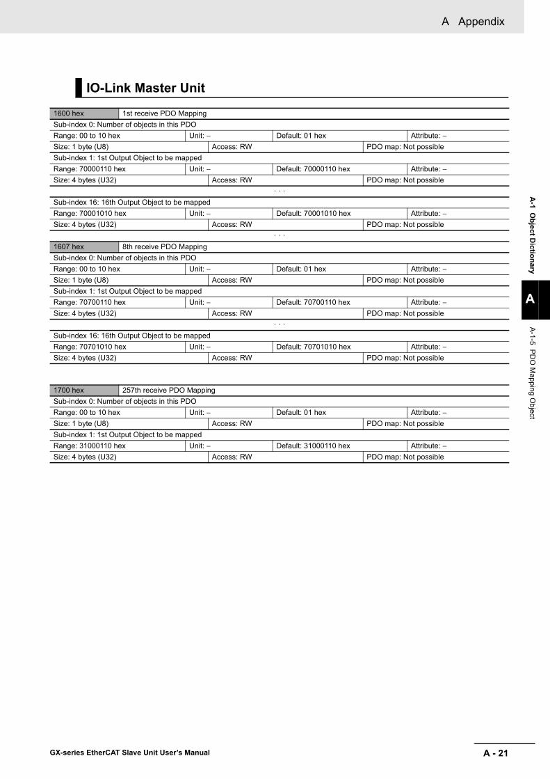
A - 21
A Appendix
GX-series EtherCAT Slave Unit User’s Manual
A-1 O
bject Dictionary
A
A-1-5 P
DO
Mapping O
bject
IO-Link Master Unit
1600 hex 1st receive PDO MappingSub-index 0: Number of objects in this PDORange: 00 to 10 hex Unit: − Default: 01 hex Attribute: −Size: 1 byte (U8) Access: RW PDO map: Not possibleSub-index 1: 1st Output Object to be mappedRange: 70000110 hex Unit: − Default: 70000110 hex Attribute: −Size: 4 bytes (U32) Access: RW PDO map: Not possible
· · ·Sub-index 16: 16th Output Object to be mappedRange: 70001010 hex Unit: − Default: 70001010 hex Attribute: −Size: 4 bytes (U32) Access: RW PDO map: Not possible
· · ·1607 hex 8th receive PDO MappingSub-index 0: Number of objects in this PDORange: 00 to 10 hex Unit: − Default: 01 hex Attribute: −Size: 1 byte (U8) Access: RW PDO map: Not possibleSub-index 1: 1st Output Object to be mappedRange: 70700110 hex Unit: − Default: 70700110 hex Attribute: −Size: 4 bytes (U32) Access: RW PDO map: Not possible
· · ·Sub-index 16: 16th Output Object to be mappedRange: 70701010 hex Unit: − Default: 70701010 hex Attribute: −Size: 4 bytes (U32) Access: RW PDO map: Not possible
1700 hex 257th receive PDO MappingSub-index 0: Number of objects in this PDORange: 00 to 10 hex Unit: − Default: 01 hex Attribute: −Size: 1 byte (U8) Access: RW PDO map: Not possibleSub-index 1: 1st Output Object to be mappedRange: 31000110 hex Unit: − Default: 31000110 hex Attribute: −Size: 4 bytes (U32) Access: RW PDO map: Not possible
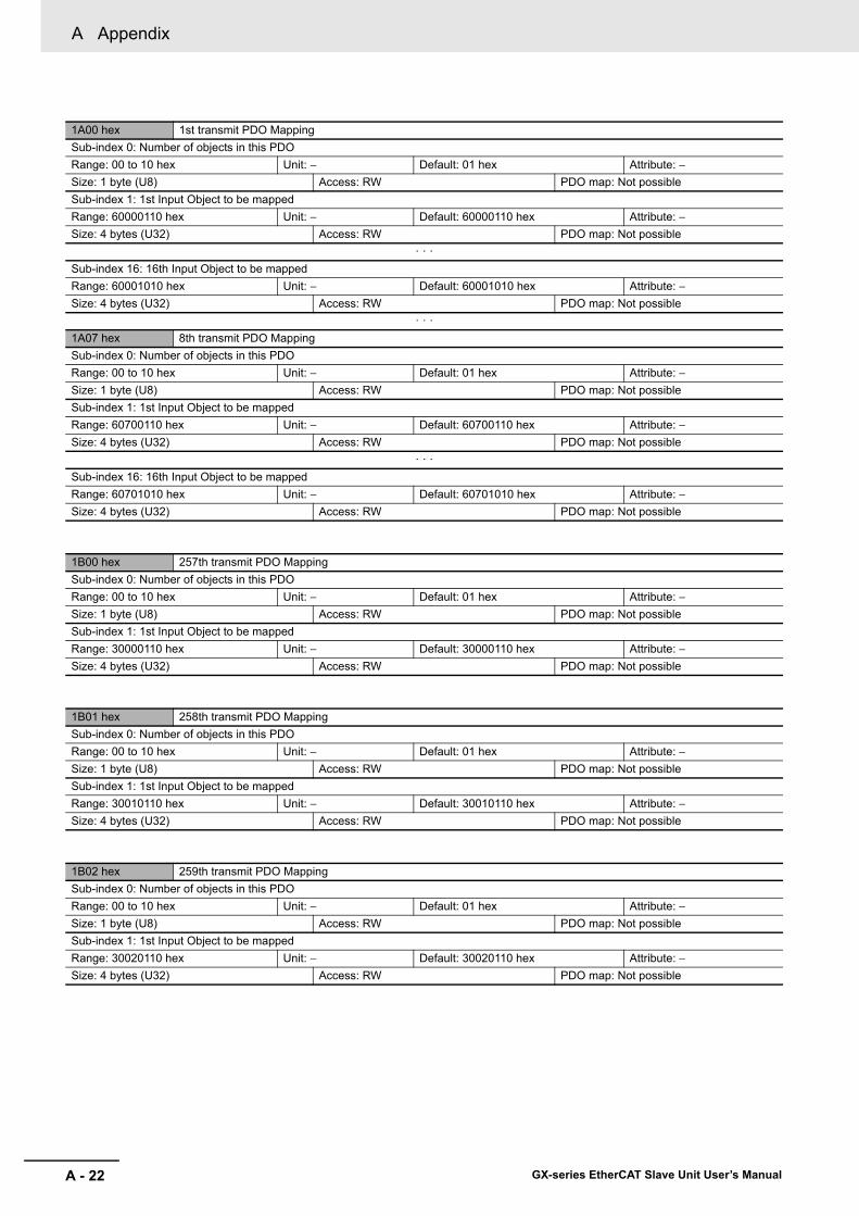
A Appendix
A - 22 GX-series EtherCAT Slave Unit User’s Manual
1A00 hex 1st transmit PDO MappingSub-index 0: Number of objects in this PDORange: 00 to 10 hex Unit: − Default: 01 hex Attribute: −Size: 1 byte (U8) Access: RW PDO map: Not possibleSub-index 1: 1st Input Object to be mappedRange: 60000110 hex Unit: − Default: 60000110 hex Attribute: −Size: 4 bytes (U32) Access: RW PDO map: Not possible
· · ·Sub-index 16: 16th Input Object to be mappedRange: 60001010 hex Unit: − Default: 60001010 hex Attribute: −Size: 4 bytes (U32) Access: RW PDO map: Not possible
· · ·1A07 hex 8th transmit PDO MappingSub-index 0: Number of objects in this PDORange: 00 to 10 hex Unit: − Default: 01 hex Attribute: −Size: 1 byte (U8) Access: RW PDO map: Not possibleSub-index 1: 1st Input Object to be mappedRange: 60700110 hex Unit: − Default: 60700110 hex Attribute: −Size: 4 bytes (U32) Access: RW PDO map: Not possible
· · ·Sub-index 16: 16th Input Object to be mappedRange: 60701010 hex Unit: − Default: 60701010 hex Attribute: −Size: 4 bytes (U32) Access: RW PDO map: Not possible
1B00 hex 257th transmit PDO MappingSub-index 0: Number of objects in this PDORange: 00 to 10 hex Unit: − Default: 01 hex Attribute: −Size: 1 byte (U8) Access: RW PDO map: Not possibleSub-index 1: 1st Input Object to be mappedRange: 30000110 hex Unit: − Default: 30000110 hex Attribute: −Size: 4 bytes (U32) Access: RW PDO map: Not possible
1B01 hex 258th transmit PDO MappingSub-index 0: Number of objects in this PDORange: 00 to 10 hex Unit: − Default: 01 hex Attribute: −Size: 1 byte (U8) Access: RW PDO map: Not possibleSub-index 1: 1st Input Object to be mappedRange: 30010110 hex Unit: − Default: 30010110 hex Attribute: −Size: 4 bytes (U32) Access: RW PDO map: Not possible
1B02 hex 259th transmit PDO MappingSub-index 0: Number of objects in this PDORange: 00 to 10 hex Unit: − Default: 01 hex Attribute: −Size: 1 byte (U8) Access: RW PDO map: Not possibleSub-index 1: 1st Input Object to be mappedRange: 30020110 hex Unit: − Default: 30020110 hex Attribute: −Size: 4 bytes (U32) Access: RW PDO map: Not possible

A - 23
A Appendix
GX-series EtherCAT Slave Unit User’s Manual
A-1 O
bject Dictionary
A
A-1-5 P
DO
Mapping O
bject
1B03 hex 260th transmit PDO MappingSub-index 0: Number of objects in this PDORange: 00 to 10 hex Unit: − Default: 01 hex Attribute: −Size: 1 byte (U8) Access: RW PDO map: Not possibleSub-index 1: 1st Input Object to be mappedRange: 30030110 hex Unit: − Default: 30030110 hex Attribute: −Size: 4 bytes (U32) Access: RW PDO map: Not possible
1B04 hex 261th transmit PDO MappingSub-index 0: Number of objects in this PDORange: 00 to 10 hex Unit: − Default: 01 hex Attribute: −Size: 1 byte (U8) Access: RW PDO map: Not possibleSub-index 1: 1st Input Object to be mappedRange: 30040110 hex Unit: − Default: 30040110 hex Attribute: −Size: 4 bytes (U32) Access: RW PDO map: Not possible
1B05 hex 262th transmit PDO MappingSub-index 0: Number of objects in this PDORange: 00 to 10 hex Unit: − Default: 01 hex Attribute: −Size: 1 byte (U8) Access: RW PDO map: Not possibleSub-index 1: 1st Input Object to be mappedDefault: 30050110 hex Unit: − Range: 30050110 hex Attribute: −Size: 4 bytes (U32) Access: RW PDO map: Not possible
1BFE hex 511th transmit PDO MappingSub-index 0: Number of objects in this PDORange: 00 to 10 hex Unit: − Default: 01 hex Attribute: −Size: 1 byte (U8) Access: RW PDO map: Not possibleSub-index 1: 1st Input Object to be mappedRange: 10F30401 hex Unit: − Default: 10F30401 hex Attribute: −Size: 4 bytes (U32) Access: RW PDO map: Not possibleSub-index 2: 2nd Input Object to be mappedRange: 00000007 hex Unit: − Default: 00000007 hex Attribute: −Size: 4 bytes (U32) Access: RW PDO map: Not possible
1BFF hex 512th transmit PDO MappingSub-index 0: Number of objects in this PDORange: 00 to 10 hex Unit: − Default: 01 hex Attribute: −Size: 1 byte (U8) Access: RW PDO map: Not possibleSub-index 1: 1st Input Object to be mappedRange: 20020108 hex Unit: − Default: 20020108 hex Attribute: −Size: 4 bytes (U32) Access: RW PDO map: Not possible
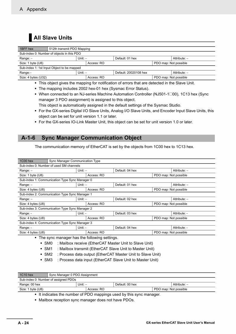
A Appendix
A - 24 GX-series EtherCAT Slave Unit User’s Manual
• This object gives the mapping for notification of errors that are detected in the Slave Unit.• The mapping includes 2002 hex-01 hex (Sysmac Error Status).• When connected to an NJ-series Machine Automation Controller (NJ501-1@00), 1C13 hex (Sync
manager 3 PDO assignment) is assigned to this object.This object is automatically assigned in the default settings of the Sysmac Studio.
• For the GX-series Digital I/O Slave Units, Analog I/O Slave Units, and Encoder Input Slave Units, this object can be set for unit version 1.1 or later.
• For the GX-series IO-Link Master Unit, this object can be set for unit version 1.0 or later.
The communication memory of EtherCAT is set by the objects from 1C00 hex to 1C13 hex.
• The sync manager has the following settings.• SM0 : Mailbox receive (EtherCAT Master Unit to Slave Unit)• SM1 : Mailbox transmit (EtherCAT Slave Unit to Master Unit)• SM2 : Process data output (EtherCAT Master Unit to Slave Unit)• SM3 : Process data input (EtherCAT Slave Unit to Master Unit)
• It indicates the number of PDO mappings used by this sync manager.• Mailbox reception sync manager does not have PDOs.
All Slave Units
1BFF hex 512th transmit PDO MappingSub-index 0: Number of objects in this PDORange: − Unit: − Default: 01 hex Attribute: −Size: 1 byte (U8) Access: RO PDO map: Not possibleSub-index 1: 1st Input Object to be mappedRange:− Unit: − Default: 20020108 hex Attribute: −Size: 4 bytes (U32) Access: RO PDO map: Not possible
A-1-6 Sync Manager Communication Object
1C00 hex Sync Manager Communication TypeSub-index 0: Number of used SM channelsRange: − Unit: − Default: 04 hex Attribute: −Size: 1 byte (U8) Access: RO PDO map: Not possibleSub-index 1: Communication Type Sync Manager 0Range: − Unit: − Default: 01 hex Attribute: −Size: 4 bytes (U8) Access: RO PDO map: Not possibleSub-index 2: Communication Type Sync Manager 1Range: − Unit: − Default: 02 hex Attribute: −Size: 4 bytes (U8) Access: RO PDO map: Not possibleSub-index 3: Communication Type Sync Manager 2Range: - Unit: - Default: 03 hex Attribute: -Size: 4 bytes (U8) Access: RO PDO map: Not possibleSub-index 4: Communication Type Sync Manager 3Range: - Unit: - Default: 04 hex Attribute: -Size: 4 bytes (U8) Access: RO PDO map: Not possible
1C10 hex Sync Manager 0 PDO AssignmentSub-index 0: Number of assigned PDOsRange: 00 hex Unit: − Default: 00 hex Attribute: −Size: 1 byte (U8) Access: RO PDO map: Not possible
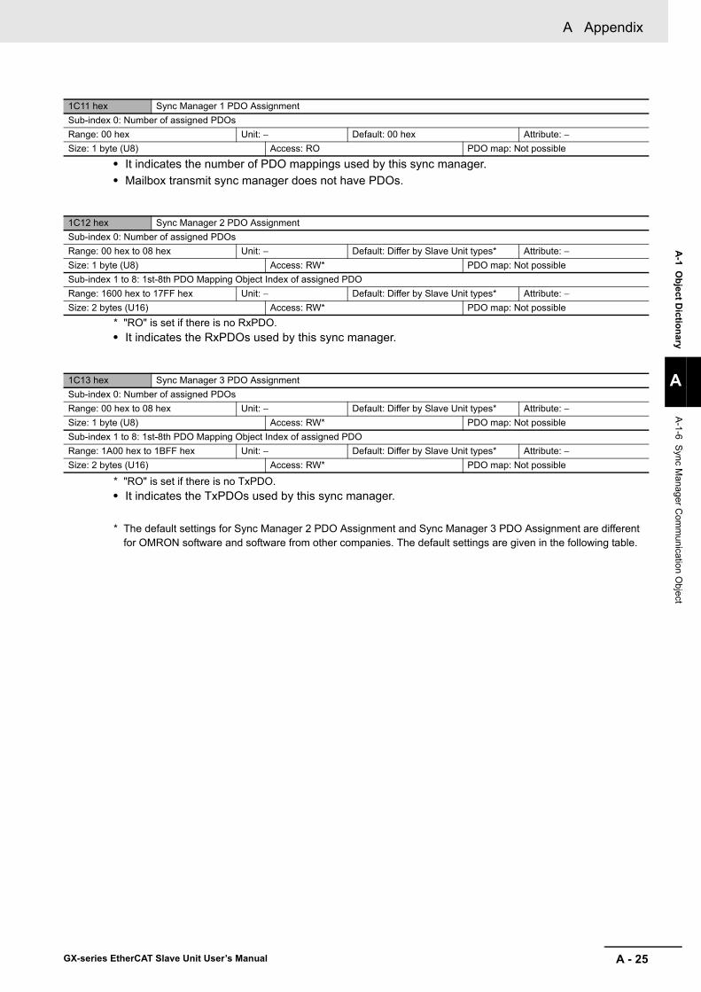
A - 25
A Appendix
GX-series EtherCAT Slave Unit User’s Manual
A-1 O
bject Dictionary
A
A-1-6 S
ync Manager C
omm
unication Object
• It indicates the number of PDO mappings used by this sync manager.• Mailbox transmit sync manager does not have PDOs.
* "RO" is set if there is no RxPDO. • It indicates the RxPDOs used by this sync manager.
* "RO" is set if there is no TxPDO. • It indicates the TxPDOs used by this sync manager.
* The default settings for Sync Manager 2 PDO Assignment and Sync Manager 3 PDO Assignment are different for OMRON software and software from other companies. The default settings are given in the following table.
1C11 hex Sync Manager 1 PDO AssignmentSub-index 0: Number of assigned PDOsRange: 00 hex Unit: − Default: 00 hex Attribute: −Size: 1 byte (U8) Access: RO PDO map: Not possible
1C12 hex Sync Manager 2 PDO AssignmentSub-index 0: Number of assigned PDOsRange: 00 hex to 08 hex Unit: − Default: Differ by Slave Unit types* Attribute: −Size: 1 byte (U8) Access: RW* PDO map: Not possibleSub-index 1 to 8: 1st-8th PDO Mapping Object Index of assigned PDORange: 1600 hex to 17FF hex Unit: − Default: Differ by Slave Unit types* Attribute: −Size: 2 bytes (U16) Access: RW* PDO map: Not possible
1C13 hex Sync Manager 3 PDO AssignmentSub-index 0: Number of assigned PDOsRange: 00 hex to 08 hex Unit: − Default: Differ by Slave Unit types* Attribute: −Size: 1 byte (U8) Access: RW* PDO map: Not possibleSub-index 1 to 8: 1st-8th PDO Mapping Object Index of assigned PDORange: 1A00 hex to 1BFF hex Unit: − Default: Differ by Slave Unit types* Attribute: −Size: 2 bytes (U16) Access: RW* PDO map: Not possible
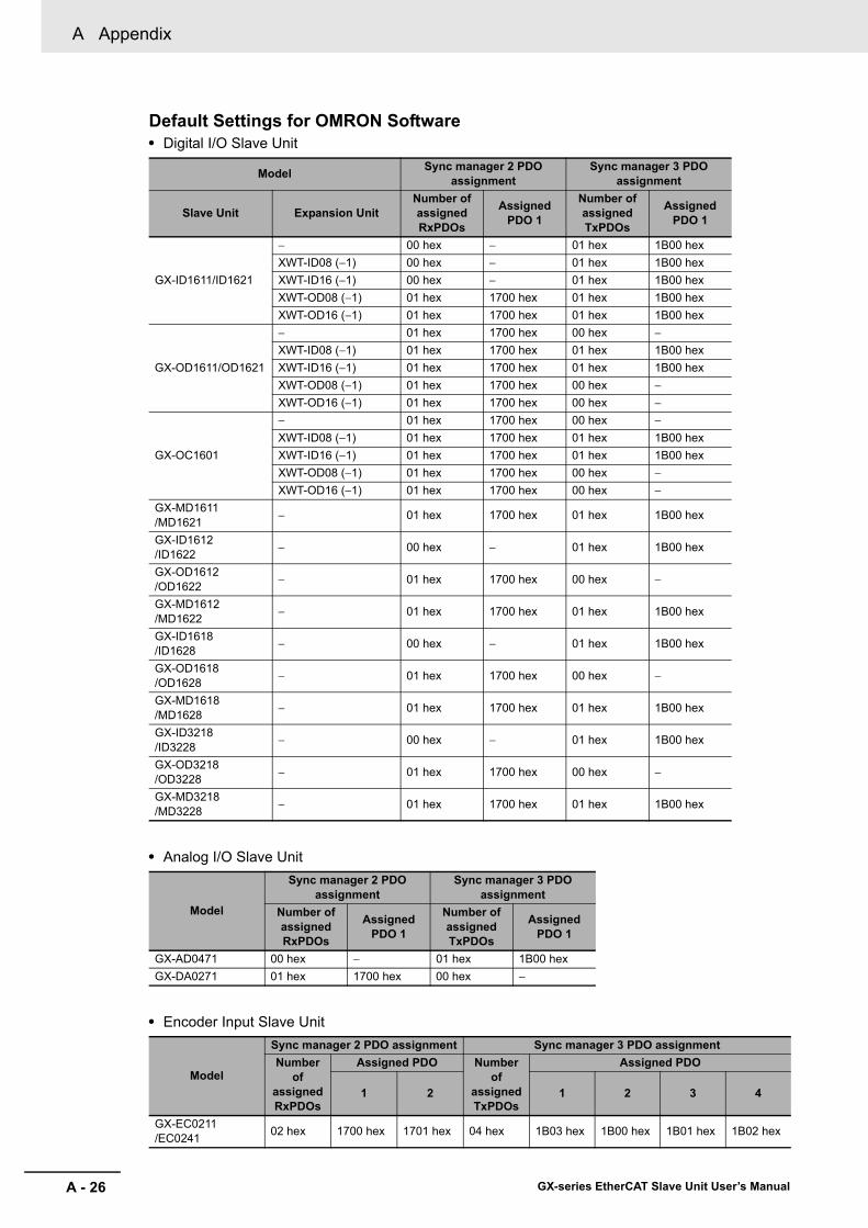
A Appendix
A - 26 GX-series EtherCAT Slave Unit User’s Manual
Default Settings for OMRON Software• Digital I/O Slave Unit
• Analog I/O Slave Unit
• Encoder Input Slave Unit
Model Sync manager 2 PDO assignment
Sync manager 3 PDO assignment
Slave Unit Expansion UnitNumber of assigned RxPDOs
Assigned PDO 1
Number of assigned TxPDOs
Assigned PDO 1
GX-ID1611/ID1621
− 00 hex − 01 hex 1B00 hexXWT-ID08 (−1) 00 hex − 01 hex 1B00 hexXWT-ID16 (−1) 00 hex − 01 hex 1B00 hexXWT-OD08 (−1) 01 hex 1700 hex 01 hex 1B00 hexXWT-OD16 (−1) 01 hex 1700 hex 01 hex 1B00 hex
GX-OD1611/OD1621
− 01 hex 1700 hex 00 hex −XWT-ID08 (−1) 01 hex 1700 hex 01 hex 1B00 hexXWT-ID16 (−1) 01 hex 1700 hex 01 hex 1B00 hexXWT-OD08 (−1) 01 hex 1700 hex 00 hex −XWT-OD16 (−1) 01 hex 1700 hex 00 hex −
GX-OC1601
− 01 hex 1700 hex 00 hex −XWT-ID08 (−1) 01 hex 1700 hex 01 hex 1B00 hexXWT-ID16 (−1) 01 hex 1700 hex 01 hex 1B00 hexXWT-OD08 (−1) 01 hex 1700 hex 00 hex −XWT-OD16 (−1) 01 hex 1700 hex 00 hex −
GX-MD1611/MD1621 − 01 hex 1700 hex 01 hex 1B00 hex
GX-ID1612/ID1622 − 00 hex − 01 hex 1B00 hex
GX-OD1612/OD1622 − 01 hex 1700 hex 00 hex −
GX-MD1612/MD1622 − 01 hex 1700 hex 01 hex 1B00 hex
GX-ID1618/ID1628 − 00 hex − 01 hex 1B00 hex
GX-OD1618/OD1628 − 01 hex 1700 hex 00 hex −
GX-MD1618/MD1628 − 01 hex 1700 hex 01 hex 1B00 hex
GX-ID3218/ID3228 − 00 hex − 01 hex 1B00 hex
GX-OD3218/OD3228 − 01 hex 1700 hex 00 hex −
GX-MD3218/MD3228 − 01 hex 1700 hex 01 hex 1B00 hex
Model
Sync manager 2 PDO assignment
Sync manager 3 PDO assignment
Number of assigned RxPDOs
Assigned PDO 1
Number of assigned TxPDOs
Assigned PDO 1
GX-AD0471 00 hex − 01 hex 1B00 hexGX-DA0271 01 hex 1700 hex 00 hex −
Model
Sync manager 2 PDO assignment Sync manager 3 PDO assignmentNumber
of assigned RxPDOs
Assigned PDO Number of
assigned TxPDOs
Assigned PDO
1 2 1 2 3 4
GX-EC0211/EC0241 02 hex 1700 hex 1701 hex 04 hex 1B03 hex 1B00 hex 1B01 hex 1B02 hex

A - 27
A Appendix
GX-series EtherCAT Slave Unit User’s Manual
A-1 O
bject Dictionary
A
A-1-6 S
ync Manager C
omm
unication Object
• IO-Link Master Unit
Model
Sync manager 2 PDO assignment
Sync manager 3 PDO assignment
Number of assigned RxPDOs
Assigned PDO 1
Number of assigned TxPDOs
Assigned PDO 1
GX-ILM08C 09 hex 1600 hex1601 hex1602 hex1603 hex1604 hex1605 hex1606 hex1607 hex1700 hex
10 hex 1A00 hex1A01 hex1A02 hex1A03 hex1A04 hex1A05 hex1A06 hex1A07 hex1B00 hex1B01 hex1B02 hex1B03 hex1B04 hex1B05 hex1BFE hex1BFF hex
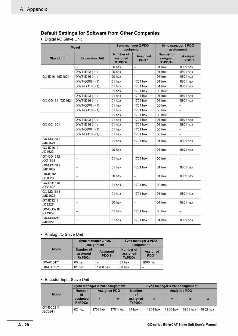
A Appendix
A - 28 GX-series EtherCAT Slave Unit User’s Manual
Default Settings for Software from Other Companies• Digital I/O Slave Unit
• Analog I/O Slave Unit
• Encoder Input Slave Unit
Model Sync manager 2 PDO assignment
Sync manager 3 PDO assignment
Slave Unit Expansion UnitNumber of assigned RxPDOs
Assigned PDO 1
Number of assigned TxPDOs
Assigned PDO 1
GX-ID1611/ID1621
− 00 hex − 01 hex 1B01 hexXWT-ID08 (−1) 00 hex − 01 hex 1B01 hexXWT-ID16 (−1) 00 hex − 01 hex 1B01 hexXWT-OD08 (−1) 01 hex 1701 hex 01 hex 1B01 hexXWT-OD16 (−1) 01 hex 1701 hex 01 hex 1B01 hex
GX-OD1611/OD1621
− 01 hex 1701 hex 00 hex −XWT-ID08 (−1) 01 hex 1701 hex 01 hex 1B01 hexXWT-ID16 (−1) 01 hex 1701 hex 01 hex 1B01 hexXWT-OD08 (−1) 01 hex 1701 hex 00 hex −XWT-OD16 (−1) 01 hex 1701 hex 00 hex −
GX-OC1601
− 01 hex 1701 hex 00 hex −XWT-ID08 (−1) 01 hex 1701 hex 01 hex 1B01 hexXWT-ID16 (−1) 01 hex 1701 hex 01 hex 1B01 hexXWT-OD08 (−1) 01 hex 1701 hex 00 hex −XWT-OD16 (−1) 01 hex 1701 hex 00 hex −
GX-MD1611/MD1621 − 01 hex 1701 hex 01 hex 1B01 hex
GX-ID1612/ID1622 − 00 hex − 01 hex 1B01 hex
GX-OD1612/OD1622 − 01 hex 1701 hex 00 hex −
GX-MD1612/MD1622 − 01 hex 1701 hex 01 hex 1B01 hex
GX-ID1618/ID1628 − 00 hex − 01 hex 1B01 hex
GX-OD1618/OD1628 − 01 hex 1701 hex 00 hex −
GX-MD1618/MD1628 − 01 hex 1701 hex 01 hex 1B01 hex
GX-ID3218/ID3228 − 00 hex − 01 hex 1B01 hex
GX-OD3218/OD3228 − 01 hex 1701 hex 00 hex −
GX-MD3218/MD3228 − 01 hex 1701 hex 01 hex 1B01 hex
Model
Sync manager 2 PDO assignment
Sync manager 3 PDO assignment
Number of assigned RxPDOs
Assigned PDO 1
Number of assigned TxPDOs
Assigned PDO 1
GX-AD0471 00 hex − 01 hex 1B00 hexGX-DA0271 01 hex 1700 hex 00 hex −
Model
Sync manager 2 PDO assignment Sync manager 3 PDO assignmentNumber
of assigned RxPDOs
Assigned PDO Number of
assigned TxPDOs
Assigned PDO
1 2 1 2 3 4
GX-EC0211/EC0241 02 hex 1702 hex 1701 hex 04 hex 1B04 hex 1B00 hex 1B01 hex 1B02 hex

A - 29
A Appendix
GX-series EtherCAT Slave Unit User’s Manual
A-1 O
bject Dictionary
A
A-1-7 M
anufacturer Specific Objects
• IO-Link Master Unit
Precautions for Correct Use
You cannot assign 1700 hex and 1701 hex or 1B00 hex and 1B01 hex for Digital I/O Slave Units at the same time. You cannot assign 1700 hex and 1702 hex or 1B03 hex and 1B04 hex for Encoder Input Slave Units at the same time. When using the OMRON Support Software, only 1700 hex and 1B00 hex can be set for Digital I/O Slave Units and only 1700 hex and 1B03 hex can be set for Encoder Input Slave Units.
This section explains the CiA401 generic I/O module device profile implemented in GX-series EtherCAT Slave Units and the objects specially mounted in GX-series EtherCAT Slave Units.
Manufacturer Specific area 1
• This object clears diagnosis history of 10F3 hex (Diagnosis History).• It clears the history only when specific values are written. The specific value is "elcl".
Writing values other than this is invalid.
Model
Sync manager 2 PDO assignment
Sync manager 3 PDO assignment
Number of assigned RxPDOs
Assigned PDO 1
Number of assigned TxPDOs
Assigned PDO 1
GX-ILM08C 09 hex 1600 hex1601 hex1602 hex1603 hex1604 hex1605 hex1606 hex1607 hex1700 hex
10 hex 1A00 hex1A01 hex1A02 hex1A03 hex1A04 hex1A05 hex1A06 hex1A07 hex1B00 hex1B01 hex1B02 hex1B03 hex1B04 hex1B05 hex1BFE hex1BFF hex
A-1-7 Manufacturer Specific Objects
All Slave Units
2100 hex Error History ClearRange: − Unit: − Default: 00000000 hex Attribute: ASize: 4 bytes (U32) Access: RW PDO map: Not possible
MSB LSBl c l e6C hex 63 hex 6C hex 65 hex
2002 hex Sysmac ErrorSub-index 0: Number of entriesRange: − Unit: − Default: 02 hex Attribute: −Size: 1 byte (U8) Access: RO PDO map: Not possibleSub-index 1: Sysmac Error StatusRange: − Unit: − Default: 00 hex Attribute: −
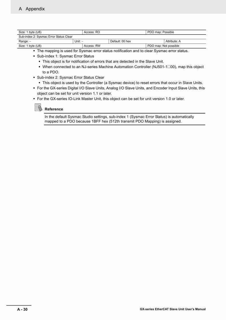
A Appendix
A - 30 GX-series EtherCAT Slave Unit User’s Manual
• The mapping is used for Sysmac error status notification and to clear Sysmac error status.• Sub-index 1: Sysmac Error Status
• This object is for notification of errors that are detected in the Slave Unit.• When connected to an NJ-series Machine Automation Controller (NJ501-1@00), map this object
to a PDO.• Sub-index 2: Sysmac Error Status Clear
• This object is used by the Controller (a Sysmac device) to reset errors that occur in Slave Units.• For the GX-series Digital I/O Slave Units, Analog I/O Slave Units, and Encoder Input Slave Units, this
object can be set for unit version 1.1 or later.• For the GX-series IO-Link Master Unit, this object can be set for unit version 1.0 or later.
Reference
In the default Sysmac Studio settings, sub-index 1 (Sysmac Error Status) is automatically mapped to a PDO because 1BFF hex (512th transmit PDO Mapping) is assigned.
Size: 1 byte (U8) Access: RO PDO map: PossibleSub-index 2: Sysmac Error Status ClearRange: − Unit: − Default: 00 hex Attribute: ASize: 1 byte (U8) Access: RW PDO map: Not possible
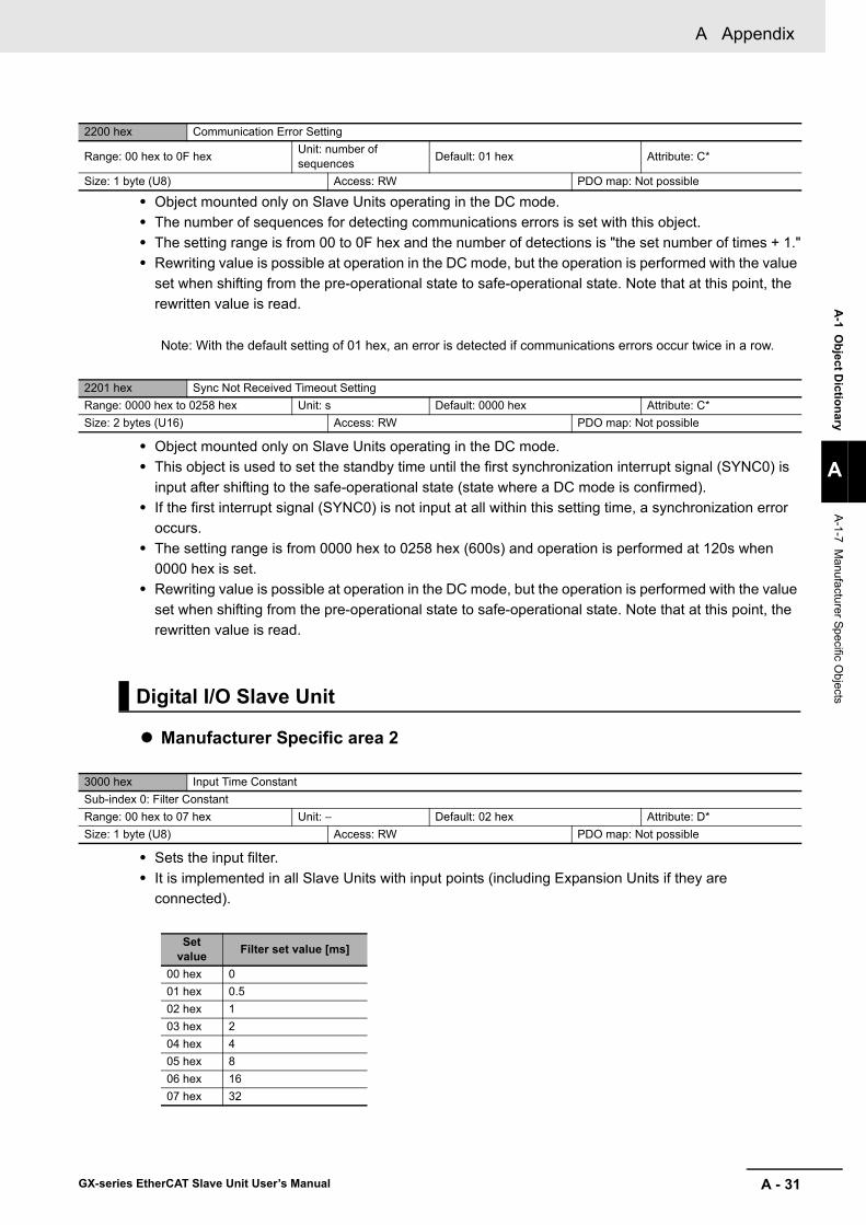
A - 31
A Appendix
GX-series EtherCAT Slave Unit User’s Manual
A-1 O
bject Dictionary
A
A-1-7 M
anufacturer Specific Objects
• Object mounted only on Slave Units operating in the DC mode.• The number of sequences for detecting communications errors is set with this object. • The setting range is from 00 to 0F hex and the number of detections is "the set number of times + 1."• Rewriting value is possible at operation in the DC mode, but the operation is performed with the value
set when shifting from the pre-operational state to safe-operational state. Note that at this point, the rewritten value is read.
Note: With the default setting of 01 hex, an error is detected if communications errors occur twice in a row.
• Object mounted only on Slave Units operating in the DC mode.• This object is used to set the standby time until the first synchronization interrupt signal (SYNC0) is
input after shifting to the safe-operational state (state where a DC mode is confirmed).• If the first interrupt signal (SYNC0) is not input at all within this setting time, a synchronization error
occurs.• The setting range is from 0000 hex to 0258 hex (600s) and operation is performed at 120s when
0000 hex is set.• Rewriting value is possible at operation in the DC mode, but the operation is performed with the value
set when shifting from the pre-operational state to safe-operational state. Note that at this point, the rewritten value is read.
Manufacturer Specific area 2
• Sets the input filter.• It is implemented in all Slave Units with input points (including Expansion Units if they are
connected).
2200 hex Communication Error Setting
Range: 00 hex to 0F hex Unit: number of sequences Default: 01 hex Attribute: C*
Size: 1 byte (U8) Access: RW PDO map: Not possible
2201 hex Sync Not Received Timeout SettingRange: 0000 hex to 0258 hex Unit: s Default: 0000 hex Attribute: C*Size: 2 bytes (U16) Access: RW PDO map: Not possible
Digital I/O Slave Unit
3000 hex Input Time ConstantSub-index 0: Filter ConstantRange: 00 hex to 07 hex Unit: − Default: 02 hex Attribute: D*Size: 1 byte (U8) Access: RW PDO map: Not possible
Set value Filter set value [ms]
00 hex 001 hex 0.502 hex 103 hex 204 hex 405 hex 806 hex 1607 hex 32

A Appendix
A - 32 GX-series EtherCAT Slave Unit User’s Manual
3020 hex Read input bitsSub-index 0: Number of input bitsRange: 00 hex to 32 hex Unit: − Default: Differ by Slave Unit types Attribute: −Size: 1 byte (U8) Access: RO PDO map: Not possibleSub-index 1: Input Bit00Range: 00 hex to 01 hex Unit: − Default: 00 hex Attribute: −Size: 1 byte (BOOL) Access: RO PDO map: PossibleSub-index 2: Input Bit01Range: 00 hex to 01 hex Unit: − Default: 00 hex Attribute: −Size: 1 byte (BOOL) Access: RO PDO map: PossibleSub-index 3: Input Bit02Range: 00 hex to 01 hex Unit: − Default: 00 hex Attribute: −Size: 1 byte (BOOL) Access: RO PDO map: PossibleSub-index 4: Input Bit03Range: 00 hex to 01 hex Unit: − Default: 00 hex Attribute: −Size: 1 byte (BOOL) Access: RO PDO map: PossibleSub-index 5: Input Bit04Range: 00 hex to 01 hex Unit: − Default: 00 hex Attribute: −Size: 1 byte (BOOL) Access: RO PDO map: PossibleSub-index 6: Input Bit05Range: 00 hex to 01 hex Unit: − Default: 00 hex Attribute: −Size: 1 byte (BOOL) Access: RO PDO map: PossibleSub-index 7: Input Bit06Range: 00 hex to 01 hex Unit: − Default: 00 hex Attribute: −Size: 1 byte (BOOL) Access: RO PDO map: PossibleSub-index 8: Input Bit07Range: 00 hex to 01 hex Unit: − Default: 00 hex Attribute: −Size: 1 byte (BOOL) Access: RO PDO map: PossibleSub-index 9: Input Bit08Range: 00 hex to 01 hex Unit: − Default: 00 hex Attribute: −Size: 1 byte (BOOL) Access: RO PDO map: PossibleSub-index 10: Input Bit09Range: 00 hex to 01 hex Unit: − Default: 00 hex Attribute: −Size: 1 byte (BOOL) Access: RO PDO map: PossibleSub-index 11: Input Bit10Range: 00 hex to 01 hex Unit: − Default: 00 hex Attribute: −Size: 1 byte (BOOL) Access: RO PDO map: PossibleSub-index 12: Input Bit11Range: 00 hex to 01 hex Unit: − Default: 00 hex Attribute: −Size: 1 byte (BOOL) Access: RO PDO map: PossibleSub-index 13: Input Bit12Range: 00 hex to 01 hex Unit: − Default: 00 hex Attribute: −Size: 1 byte (BOOL) Access: RO PDO map: PossibleSub-index 14: Input Bit13Range: 00 hex to 01 hex Unit: − Default: 00 hex Attribute: −Size: 1 byte (BOOL) Access: RO PDO map: PossibleSub-index 15: Input Bit14Range: 00 hex to 01 hex Unit: − Default: 00 hex Attribute: −Size: 1 byte (BOOL) Access: RO PDO map: PossibleSub-index 16: Input Bit15Range: 00 hex to 01 hex Unit: − Default: 00 hex Attribute: −Size: 1 byte (BOOL) Access: RO PDO map: PossibleSub-index 17: Input Bit16Range: 00 hex to 01 hex Unit: − Default: 00 hex Attribute: −Size: 1 byte (BOOL) Access: RO PDO map: PossibleSub-index 18: Input Bit17Range: 00 hex to 01 hex Unit: − Default: 00 hex Attribute: −Size: 1 byte (BOOL) Access: RO PDO map: Possible

A - 33
A Appendix
GX-series EtherCAT Slave Unit User’s Manual
A-1 O
bject Dictionary
A
A-1-7 M
anufacturer Specific Objects
• The digital input values are stored in 1-bit units.• Unit version 1.1 or later is required to set this object.
Sub-index 19: Input Bit18Range: 00 hex to 01 hex Unit: − Default: 00 hex Attribute: −Size: 1 byte (BOOL) Access: RO PDO map: PossibleSub-index 20: Input Bit19Range: 00 hex to 01 hex Unit: − Default: 00 hex Attribute: −Size: 1 byte (BOOL) Access: RO PDO map: PossibleSub-index 21: Input Bit20Range: 00 hex to 01 hex Unit: − Default: 00 hex Attribute: −Size: 1 byte (BOOL) Access: RO PDO map: PossibleSub-index 22: Input Bit21Range: 00 hex to 01 hex Unit: − Default: 00 hex Attribute: −Size: 1 byte (BOOL) Access: RO PDO map: PossibleSub-index 23: Input Bit22Range: 00 hex to 01 hex Unit: − Default: 00 hex Attribute: −Size: 1 byte (BOOL) Access: RO PDO map: PossibleSub-index 24: Input Bit23Range: 00 hex to 01 hex Unit: − Default: 00 hex Attribute: −Size: 1 byte (BOOL) Access: RO PDO map: PossibleSub-index 25: Input Bit24Range: 00 hex to 01 hex Unit: − Default: 00 hex Attribute: −Size: 1 byte (BOOL) Access: RO PDO map: PossibleSub-index 26: Input Bit25Range: 00 hex to 01 hex Unit: − Default: 00 hex Attribute: −Size: 1 byte (BOOL) Access: RO PDO map: PossibleSub-index 27: Input Bit26Range: 00 hex to 01 hex Unit: − Default: 00 hex Attribute: −Size: 1 byte (BOOL) Access: RO PDO map: PossibleSub-index 28: Input Bit27Range: 00 hex to 01 hex Unit: − Default: 00 hex Attribute: −Size: 1 byte (BOOL) Access: RO PDO map: PossibleSub-index 29: Input Bit28Range: 00 hex to 01 hex Unit: − Default: 00 hex Attribute: −Size: 1 byte (BOOL) Access: RO PDO map: PossibleSub-index 30: Input Bit29Range: 00 hex to 01 hex Unit: − Default: 00 hex Attribute: −Size: 1 byte (BOOL) Access: RO PDO map: PossibleSub-index 31: Input Bit30Range: 00 hex to 01 hex Unit: − Default: 00 hex Attribute: −Size: 1 byte (BOOL) Access: RO PDO map: PossibleSub-index 32: Input Bit31Range: 00 hex to 01 hex Unit: − Default: 00 hex Attribute: −Size: 1 byte (BOOL) Access: RO PDO map: Possible

A Appendix
A - 34 GX-series EtherCAT Slave Unit User’s Manual
3220 hex Read output bitsSub-index 0: Number of output bitsRange: 00 hex to 32 hex Unit: − Default: Differ by Slave Unit types* Attribute: −Size: 1 byte (U8) Access: RO PDO map: Not possibleSub-index 1: Output Bit00Range: 00 hex to 01 hex Unit: − Default: 00 hex Attribute: ASize: 1 byte (BOOL) Access: RW PDO map: PossibleSub-index 2: Output Bit01Range: 00 hex to 01 hex Unit: − Default: 00 hex Attribute: ASize: 1 byte (BOOL) Access: RW PDO map: PossibleSub-index 3: Output Bit02Range: 00 hex to 01 hex Unit: − Default: 00 hex Attribute: ASize: 1 byte (BOOL) Access: RW PDO map: PossibleSub-index 4: Output Bit03Range: 00 hex to 01 hex Unit: − Default: 00 hex Attribute: ASize: 1 byte (BOOL) Access: RW PDO map: PossibleSub-index 5: Output Bit04Range: 00 hex to 01 hex Unit: − Default: 00 hex Attribute: ASize: 1 byte (BOOL) Access: RW PDO map: PossibleSub-index 6: Output Bit05Range: 00 hex to 01 hex Unit: − Default: 00 hex Attribute: ASize: 1 byte (BOOL) Access: RW PDO map: PossibleSub-index 7: Output Bit06Range: 00 hex to 01 hex Unit: − Default: 00 hex Attribute: ASize: 1 byte (BOOL) Access: RW PDO map: PossibleSub-index 8: Output Bit07Range: 00 hex to 01 hex Unit: − Default: 00 hex Attribute: ASize: 1 byte (BOOL) Access: RW PDO map: PossibleSub-index 9: Output Bit08Range: 00 hex to 01 hex Unit: − Default: 00 hex Attribute: ASize: 1 byte (BOOL) Access: RW PDO map: PossibleSub-index 10: Output Bit09Range: 00 hex to 01 hex Unit: − Default: 00 hex Attribute: ASize: 1 byte (BOOL) Access: RW PDO map: PossibleSub-index 11: Output Bit10Range: 00 hex to 01 hex Unit: − Default: 00 hex Attribute: ASize: 1 byte (BOOL) Access: RW PDO map: PossibleSub-index 12: Output Bit11Range: 00 hex to 01 hex Unit: − Default: 00 hex Attribute: ASize: 1 byte (BOOL) Access: RW PDO map: PossibleSub-index 13: Output Bit12Range: 00 hex to 01 hex Unit: − Default: 00 hex Attribute: ASize: 1 byte (BOOL) Access: RW PDO map: PossibleSub-index 14: Output Bit13Range: 00 hex to 01 hex Unit: − Default: 00 hex Attribute: ASize: 1 byte (BOOL) Access: RW PDO map: PossibleSub-index 15: Output Bit14Range: 00 hex to 01 hex Unit: − Default: 00 hex Attribute: ASize: 1 byte (BOOL) Access: RW PDO map: PossibleSub-index 16: Output Bit15Range: 00 hex to 01 hex Unit: − Default: 00 hex Attribute: ASize: 1 byte (BOOL) Access: RW PDO map: PossibleSub-index 17: Output Bit16Range: 00 hex to 01 hex Unit: − Default: 00 hex Attribute: ASize: 1 byte (BOOL) Access: RW PDO map: PossibleSub-index 18: Output Bit17Range: 00 hex to 01 hex Unit: − Default: 00 hex Attribute: ASize: 1 byte (BOOL) Access: RW PDO map: Possible

A - 35
A Appendix
GX-series EtherCAT Slave Unit User’s Manual
A-1 O
bject Dictionary
A
A-1-7 M
anufacturer Specific Objects
• The digital output values are stored in 1-bit units.• Unit version 1.1 or later is required to set this object.
Sub-index 19: Output Bit18Range: 00 hex to 01 hex Unit: − Default: 00 hex Attribute: ASize: 1 byte (BOOL) Access: RW PDO map: PossibleSub-index 20: Output Bit19Range: 00 hex to 01 hex Unit: − Default: 00 hex Attribute: ASize: 1 byte (BOOL) Access: RW PDO map: PossibleSub-index 21: Output Bit20Range: 00 hex to 01 hex Unit: − Default: 00 hex Attribute: ASize: 1 byte (BOOL) Access: RW PDO map: PossibleSub-index 22: Output Bit21Range: 00 hex to 01 hex Unit: − Default: 00 hex Attribute: ASize: 1 byte (BOOL) Access: RW PDO map: PossibleSub-index 23:Output Bit22Range: 00 hex to 01 hex Unit: − Default: 00 hex Attribute: ASize: 1 byte (BOOL) Access: RW PDO map: PossibleSub-index 24: Output Bit23Range: 00 hex to 01 hex Unit: − Default: 00 hex Attribute: ASize: 1 byte (BOOL) Access: RW PDO map: PossibleSub-index 25: Output Bit24Range: 00 hex to 01 hex Unit: − Default: 00 hex Attribute: ASize: 1 byte (BOOL) Access: RW PDO map: PossibleSub-index 26: Output Bit25Range: 00 hex to 01 hex Unit: − Default: 00 hex Attribute: ASize: 1 byte (BOOL) Access: RW PDO map: PossibleSub-index 27: Output Bit26Range: 00 hex to 01 hex Unit: − Default: 00 hex Attribute: ASize: 1 byte (BOOL) Access: RW PDO map: PossibleSub-index 28: Output Bit27Range: 00 hex to 01 hex Unit: − Default: 00 hex Attribute: ASize: 1 byte (BOOL) Access: RW PDO map: PossibleSub-index 29: Output Bit28Range: 00 hex to 01 hex Unit: − Default: 00 hex Attribute: ASize: 1 byte (BOOL) Access: RW PDO map: PossibleSub-index 30: Output Bit29Range: 00 hex to 01 hex Unit: − Default: 00 hex Attribute: ASize: 1 byte (BOOL) Access: RW PDO map: PossibleSub-index 31: Output Bit30Range: 00 hex to 01 hex Unit: − Default: 00 hex Attribute: ASize: 1 byte (BOOL) Access: RW PDO map: PossibleSub-index 32: Output Bit31Range: 00 hex to 01 hex Unit: − Default: 00 hex Attribute: ASize: 1 byte (BOOL) Access: RW PDO map: Possible

A Appendix
A - 36 GX-series EtherCAT Slave Unit User’s Manual
Device Profile area
• Digital input values are stored in units of 1 byte (8 bits).• It is implemented in all Slave Units with input points (including Expansion Units if they are
connected).
• Digital input values are stored in units of 2 byte (16 bits).
• Digital input values are stored in units of 4 byte (32 bits).
6000 hex Read input 8bitSub-index 0: Number of inputs 8bitRange: 00 hex to 04 hex Unit: − Default: Differ by Slave Unit types* Attribute: −Size: 1 byte (U8) Access: RO PDO map: Not possibleSub-index 1: Read input 1st byteRange: 00 hex to FF hex Unit: − Default: − Attribute: −Size: 1 byte (U8) Access: RO PDO map: Not possible*Sub-index 2: Read input 2nd byteRange: 00h to FFh Unit: − Default: − Attribute: −Size: 1 byte (U8) Access: RO PDO map: Not possibleSub-index 3: Read input 3rd byteRange: 00 hex to FF hex Unit: − Default: − Attribute: −Size: 1 byte (U8) Access: RO PDO map: Not possibleSub-index 4: Read input 4th byteRange: 00 hex to FF hex Unit: − Default: − Attribute: −Size: 1 byte (U8) Access: RO PDO map: Not possible
6100 hex Read input 16bitSub-index 0: Number of inputs 16bitRange: − Unit: − Default: 01 hex Attribute: −Size: 1 byte (U8) Access: RO PDO map: Not possibleSub-index 1: Read input 1st wordRange: 0000 hex to FFFF hex Unit: − Default: − Attribute: −Size: 2 bytes (U16) Access: RO PDO map: Possible
6120 hex Read input 32bitSub-index 0: Number of inputs 32bitRange: − Unit: − Default: 01 hex Attribute: −Size: 1 byte (U8) Access: RO PDO map: Not possibleSub-index 1: Read input 1st double wordRange: 00000000 hex to FFFFFFFF hex Unit: − Default: − Attribute: −
Size: 4 bytes (U32) Access: RO PDO map: Possible
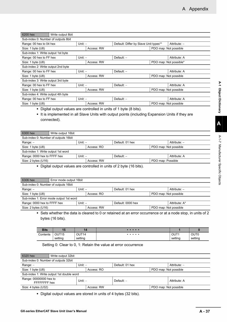
A - 37
A Appendix
GX-series EtherCAT Slave Unit User’s Manual
A-1 O
bject Dictionary
A
A-1-7 M
anufacturer Specific Objects
• Digital output values are controlled in units of 1 byte (8 bits).• It is implemented in all Slave Units with output points (including Expansion Units if they are
connected).
• Digital output values are controlled in units of 2 byte (16 bits).
• Sets whether the data is cleared to 0 or retained at an error occurrence or at a node stop, in units of 2 bytes (16 bits).
Setting 0: Clear to 0, 1: Retain the value at error occurrence
• Digital output values are stored in units of 4 bytes (32 bits).
6200 hex Write output 8bitSub-index 0: Number of outputs 8bitRange: 00 hex to 04 hex Unit: − Default: Differ by Slave Unit types** Attribute: −Size: 1 byte (U8) Access: RW PDO map: Not possibleSub-index 1: Write output 1st byteRange: 00 hex to FF hex Unit: − Default: − Attribute: ASize: 1 byte (U8) Access: RW PDO map: Not possible*Sub-index 2: Write output 2nd byteRange: 00 hex to FF hex Unit: − Default: − Attribute: ASize: 1 byte (U8) Access: RW PDO map: Not possibleSub-index 3: Write output 3rd byteRange: 00 hex to FF hex Unit: − Default: − Attribute: ASize: 1 byte (U8) Access: RW PDO map: Not possibleSub-index 4: Write output 4th byteRange: 00 hex to FF hex Unit: − Default: − Attribute: ASize: 1 byte (U8) Access: RW PDO map: Not possible
6300 hex Write output 16bitSub-index 0: Number of outputs 16bitRange: − Unit: − Default: 01 hex Attribute: −Size: 1 byte (U8) Access: RO PDO map: Not possibleSub-index 1: Write output 1st wordRange: 0000 hex to FFFF hex Unit: − Default: − Attribute: ASize: 2 bytes (U16) Access: RW PDO map: Possible
6306 hex Error mode output 16bitSub-index 0: Number of outputs 16bitRange: − Unit: − Default: 01 hex Attribute: −Size: 1 byte (U8) Access: RO PDO map: Not possibleSub-index 1: Error mode output 1st wordRange: 0000 hex to FFFF hex Unit: − Default: 0000 hex Attribute: A*Size: 2 bytes (U16) Access: RW PDO map: Not possible
Bits 15 14 • • • • • 1 0Contents OUT15
settingOUT14 setting
• • • • • OUT1 setting
OUT0 setting
6320 hex Write output 32bitSub-index 0: Number of outputs 32bitRange: − Unit: − Default: 01 hex Attribute: −Size: 1 byte (U8) Access: RO PDO map: Not possibleSub-index 1: Write output 1st double wordRange: 00000000 hex to FFFFFFFF hex Unit: − Default: − Attribute: A
Size: 4 bytes (U32) Access: RW PDO map: Not possible

A Appendix
A - 38 GX-series EtherCAT Slave Unit User’s Manual
• Sets whether the data is cleared to 0 or retained at an error occurrence or at a node stop, in units of 4 bytes (32 bits).
Setting 0: Clear to 0, 1: Retain the value at error occurrence
6326 hex Error mode output 32bitSub-index 0: Number of outputs 32bitRange: − Unit: − Default: 01 hex Attribute: −Size: 1 byte (U8) Access: RO PDO map: Not possibleSub-index 1: Error mode output 1st double wordRange: 00000000 hex to FFFFFFFF hex
Unit: − Default: 00000000 hex Attribute: A*
Size: 4 bytes (U32) Access: RW PDO map: Possible
Bits 31 30 • • • • • 1 0Contents OUT31
settingOUT30 setting
• • • • • OUT1 setting
OUT0 setting

A - 39
A Appendix
GX-series EtherCAT Slave Unit User’s Manual
A-1 O
bject Dictionary
A
A-1-7 M
anufacturer Specific Objects
Objects of Device Profile areas that are implemented in a Digital I/O Slave Unit is determined by the number of inputs and/or outputs per Slave Unit and whether or not Expansion Units are connected.The following table shows the objects of Device Profile area that are implemented in Digital I/O Slave Unit and the number of sub-indexes.
Type
Model Number of supported sub-indexesNo: Not supported
Slave Unit Expansion Unit
Indexes 3020 hex
3220 hex
6000 hex
6100 hex
6120 hex
6200 hex
6300 hex
6306 hex
6320 hex
6326 hex
ObjectName
I/O unitscapacity
Readinputbits
Writeoutput
bits
Readinput8-bit
Readinput16-bit
Readinput32-bit
Writeoutput8-bit
Writeoutput16-bit
Errormodeoutput16-bit
Writeoutput32-bit
Errormodeoutput32-bit
2-tier terminal block
GX-ID1611/ID1621
− 16 inputs 17 No 3 2 No No No No No NoXWT-ID08 ( −1) 24 inputs 33 No 5 No 2 No No No No NoXWT-ID16 ( −1) 32 inputs 33 No 5 No 2 No No No No No
XWT-OD08 ( −1) 16 inputs and8 outputs 17 17 3 2 No 3 2 2 No No
XWT-OD16 ( −1) 16 inputs and16 outputs 17 17 3 2 No 3 2 2 No No
GX-OD1611/OD1621
XWT-ID08 ( −1) 8 inputs and16 outputs 17 17 3 2 No 3 2 2 No No
XWT-ID16 ( −1) 16 inputs and16 outputs 17 17 3 2 No 3 2 2 No No
− 16 outputs No 17 No No No 3 2 2 No NoXWT-OD08 ( −1) 24 outputs No 33 No No No 5 No No 2 2XWT-OD16 ( −1) 32 outputs No 33 No No No 5 No No 2 2
GX-OC1611
XWT-ID08 ( −1) 8 inputs and16 outputs 17 17 3 2 No 3 2 2 No No
XWT-ID16 ( −1) 16 inputs and16 outputs 17 17 3 2 No 3 2 2 No No
− 16 outputs No 17 No No No 3 2 2 No NoXWT-OD08 ( −1) 24 outputs No 33 No No No 5 No No 2 2XWT-OD16 ( −1) 32 outputs No 33 No No No 5 No No 2 2
GX-MD1611/MD1621 −
8 inputs and8 outputs 17 17 3 2 No 3 2 2 No No
3-tier terminal block
GX-ID1612/ID1622 − 16 inputs 17 No 3 2 2 No No No No No
GX-OD1612/OD1622 − 16 outputs No 17 No No No 3 2 2 No No
GX-MD1612/MD1622 −
8 inputs and8 outputs 17 17 3 2 No 3 2 2 No No
e-CONConnectors
GX-ID1618/ID1628 − 16 inputs 17 No 3 2 2 No No No No No
GX-OD1618/OD1628 − 16 outputs No 17 No No No 3 2 2 No No
GX-MD1618/MD1628 −
8 inputs and8 outputs 17 17 3 2 No 3 2 2 No No
GX-ID3218/ID3228 − 32 inputs 33 No 5 No 2 No No No No No
GX-OD3218/OD3228 − 32 outputs No 33 No No No 5 No No 2 2
GX-MD3218/MD3228 −
16 inputs and16 outputs 17 17 3 2 No 3 2 2 No No
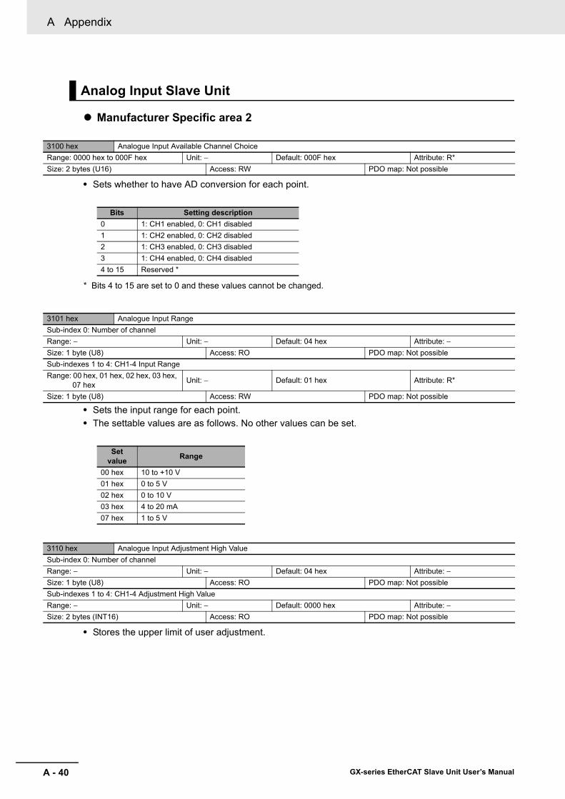
A Appendix
A - 40 GX-series EtherCAT Slave Unit User’s Manual
Manufacturer Specific area 2
• Sets whether to have AD conversion for each point.
* Bits 4 to 15 are set to 0 and these values cannot be changed.
• Sets the input range for each point.• The settable values are as follows. No other values can be set.
• Stores the upper limit of user adjustment.
Analog Input Slave Unit
3100 hex Analogue Input Available Channel ChoiceRange: 0000 hex to 000F hex Unit: − Default: 000F hex Attribute: R*Size: 2 bytes (U16) Access: RW PDO map: Not possible
Bits Setting description0 1: CH1 enabled, 0: CH1 disabled1 1: CH2 enabled, 0: CH2 disabled2 1: CH3 enabled, 0: CH3 disabled3 1: CH4 enabled, 0: CH4 disabled4 to 15 Reserved *
3101 hex Analogue Input RangeSub-index 0: Number of channelRange: − Unit: − Default: 04 hex Attribute: −Size: 1 byte (U8) Access: RO PDO map: Not possibleSub-indexes 1 to 4: CH1-4 Input RangeRange: 00 hex, 01 hex, 02 hex, 03 hex,
07 hex Unit: − Default: 01 hex Attribute: R*
Size: 1 byte (U8) Access: RW PDO map: Not possible
Set value Range
00 hex 10 to +10 V 01 hex 0 to 5 V 02 hex 0 to 10 V03 hex 4 to 20 mA07 hex 1 to 5 V
3110 hex Analogue Input Adjustment High ValueSub-index 0: Number of channelRange: − Unit: − Default: 04 hex Attribute: −Size: 1 byte (U8) Access: RO PDO map: Not possibleSub-indexes 1 to 4: CH1-4 Adjustment High ValueRange: − Unit: − Default: 0000 hex Attribute: −Size: 2 bytes (INT16) Access: RO PDO map: Not possible
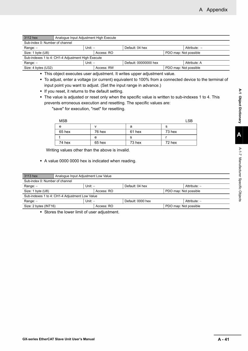
A - 41
A Appendix
GX-series EtherCAT Slave Unit User’s Manual
A-1 O
bject Dictionary
A
A-1-7 M
anufacturer Specific Objects
• This object executes user adjustment. It writes upper adjustment value. • To adjust, enter a voltage (or current) equivalent to 100% from a connected device to the terminal of
input point you want to adjust. (Set the input range in advance.)• If you reset, it returns to the default setting.• The value is adjusted or reset only when the specific value is written to sub-indexes 1 to 4. This
prevents erroneous execution and resetting. The specific values are:"save" for execution, "rset" for resetting.
Writing values other than the above is invalid.
• A value 0000 0000 hex is indicated when reading.
• Stores the lower limit of user adjustment.
3112 hex Analogue Input Adjustment High ExecuteSub-index 0: Number of channelRange: − Unit: − Default: 04 hex Attribute: −Size: 1 byte (U8) Access: RO PDO map: Not possibleSub-indexes 1 to 4: CH1-4 Adjustment High ExecuteRange: − Unit: − Default: 00000000 hex Attribute: ASize: 4 bytes (U32) Access: RW PDO map: Not possible
MSB LSBe v a s65 hex 76 hex 61 hex 73 hext e s r74 hex 65 hex 73 hex 72 hex
3113 hex Analogue Input Adjustment Low ValueSub-index 0: Number of channelRange: − Unit: − Default: 04 hex Attribute: −Size: 1 byte (U8) Access: RO PDO map: Not possibleSub-indexes 1 to 4: CH1-4 Adjustment Low ValueRange: − Unit: − Default: 0000 hex Attribute: −Size: 2 bytes (INT16) Access: RO PDO map: Not possible
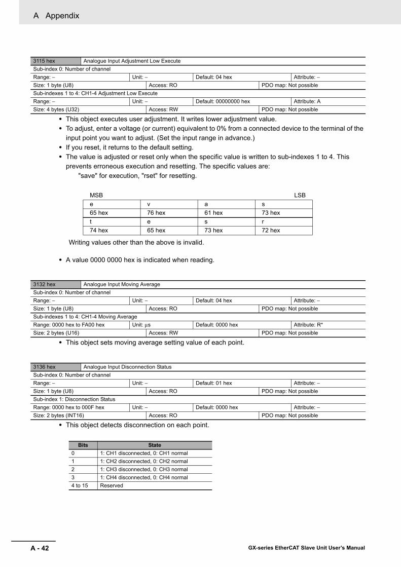
A Appendix
A - 42 GX-series EtherCAT Slave Unit User’s Manual
• This object executes user adjustment. It writes lower adjustment value. • To adjust, enter a voltage (or current) equivalent to 0% from a connected device to the terminal of the
input point you want to adjust. (Set the input range in advance.)• If you reset, it returns to the default setting.• The value is adjusted or reset only when the specific value is written to sub-indexes 1 to 4. This
prevents erroneous execution and resetting. The specific values are:"save" for execution, "rset" for resetting.
Writing values other than the above is invalid.
• A value 0000 0000 hex is indicated when reading.
• This object sets moving average setting value of each point.
• This object detects disconnection on each point.
3115 hex Analogue Input Adjustment Low ExecuteSub-index 0: Number of channelRange: − Unit: − Default: 04 hex Attribute: −Size: 1 byte (U8) Access: RO PDO map: Not possibleSub-indexes 1 to 4: CH1-4 Adjustment Low ExecuteRange: − Unit: − Default: 00000000 hex Attribute: ASize: 4 bytes (U32) Access: RW PDO map: Not possible
MSB LSBe v a s65 hex 76 hex 61 hex 73 hext e s r74 hex 65 hex 73 hex 72 hex
3132 hex Analogue Input Moving AverageSub-index 0: Number of channelRange: − Unit: − Default: 04 hex Attribute: −Size: 1 byte (U8) Access: RO PDO map: Not possibleSub-indexes 1 to 4: CH1-4 Moving AverageRange: 0000 hex to FA00 hex Unit: μs Default: 0000 hex Attribute: R*Size: 2 bytes (U16) Access: RW PDO map: Not possible
3136 hex Analogue Input Disconnection StatusSub-index 0: Number of channelRange: − Unit: − Default: 01 hex Attribute: −Size: 1 byte (U8) Access: RO PDO map: Not possibleSub-index 1: Disconnection StatusRange: 0000 hex to 000F hex Unit: − Default: 0000 hex Attribute: −Size: 2 bytes (INT16) Access: RO PDO map: Not possible
Bits State0 1: CH1 disconnected, 0: CH1 normal1 1: CH2 disconnected, 0: CH2 normal2 1: CH3 disconnected, 0: CH3 normal3 1: CH4 disconnected, 0: CH4 normal4 to 15 Reserved

A - 43
A Appendix
GX-series EtherCAT Slave Unit User’s Manual
A-1 O
bject Dictionary
A
A-1-7 M
anufacturer Specific Objects
Device Profile area
* This is equal to the set input range.
• This object indicates input of each point.
Manufacturer Specific area 2
• Sets whether to have DA conversion for each point. • Do not disable all channels.
• Sets the output range for each point.• The settable values are as follows. No other values can be set.
6401 hex Read Analogue Input 16bitSub-index 0: Number of channelRange: − Unit: − Default: 04 hex Attribute: −Size: 1 byte (U8) Access: RO PDO map: Not possibleSub-indexes 1 to 4: CH1-4 Input 16bitRange: * Unit: − Default: 0000 hex Attribute: −Size: 2 bytes (INT16) Access: RO PDO map: Possible
Analog Output Slave Unit
3200 hex Analogue Output Available Channel ChoiceRange: 0001 hex to 0003 hex Unit: − Default: 0003 hex Attribute: R*Size: 2 bytes (U16) Access: RW PDO map: Not possible
Bits D/A conversion enabled channel0 1: CH1 enabled, 0: CH1 disabled1 1: CH2 enabled, 0: CH2 disabled2 to 15 Reserved
3201 hex Analogue Output RangeSub-index 0: Number of channelRange: − Unit: − Default: 02 hex Attribute: −Size: 1 byte (U8) Access: RO PDO map: Not possibleSub-indexes 1 to 2: CH1-2 Output RangeRange: 00 hex, 01 hex, 03 hex, 04 hex,
06 hex Unit: − Default: 04 hex Attribute: R*
Size: 1 byte (U8) Access: RW PDO map: Not possible
Set value Range
00 hex 4 to 20 mA 01 hex 0 to 10 V03 hex −10 to +10 V 04 hex 0 to 5 V06 hex 1 to 5 V

A Appendix
A - 44 GX-series EtherCAT Slave Unit User’s Manual
• Stores the upper limit of user adjustment. The user upper adjustment value is stored.
• This object executes user adjustment. It writes upper adjustment value. • Execute the command when a count value which makes the actual output voltage 100% is written by
the EtherCAT Master Unit to the data area of the point to adjust. (Adjustment at 100% is highly recommended, but a lower value is acceptable.)
• If you reset, it returns to the default setting.• The values is adjusted or reset only when the specific value is written to sub-indexes 1 to 2. This
prevents erroneous execution and resetting. The specific values are:"save" for execution, "rset" for resetting.
Writing values other than the above is invalid.
• A value of 0000 0000 hex is indicated when reading.
Notes: Always adjust the lower limit first. If the lower limit is adjusted without adjusting the upper limit 100%, the lower limit adjustment may have an error.
• Stores the lower limit of user adjustment.
3210 hex Analogue Output Adjustment High ValueSub-index 0: Number of channelRange: − Unit: − Default: 02 hex Attribute: −Size: 1 byte (U8) Access: RO PDO map: Not possibleSub-indexes 1 to 2: CH1-2 Adjustment High ValueRange: − Unit: − Default: 0000 hex Attribute: −Size: 2 byte (INT16) Access: RO PDO map: Not possible
3212 hex Analogue Output Adjustment High ExecuteSub-index 0: Number of channelRange: − Unit: − Default: 02 hex Attribute: −Size: 1 byte (U8) Access: RO PDO map: Not possibleSub-indexes 1 to 2: CH1-2 Adjustment High ExecuteRange: − Unit: − Default: 00000000 hex Attribute: ASize: 4 bytes (U32) Access: RW PDO map: Not possible
MSB LSBe v a s65 hex 76 hex 61 hex 73 hext e s r74 hex 65 hex 73 hex 72 hex
3213 hex Analogue Output Adjustment Low ValueSub-index 0: Number of channelRange: − Unit: − Default: 02 hex Attribute: −Size: 1 byte (U8) Access: RO PDO map: Not possibleSub-indexes 1 to 2: CH1-2 Adjustment Low ValueRange: − Unit: − Default: 0000 hex Attribute: −Size: 2 byte (INT16) Access: RO PDO map: Not possible

A - 45
A Appendix
GX-series EtherCAT Slave Unit User’s Manual
A-1 O
bject Dictionary
A
A-1-7 M
anufacturer Specific Objects
• This object executes user adjustment. It writes lower adjustment value. • Be sure to execute the command only when a count value which makes the actual output voltage 0%
is written by the EtherCAT Master Unit to the data area of the point to adjust. (Always adjust at 0%.)• If you reset, it returns to the default setting.• The value is adjusted or reset only when the specific value is written to sub-indexes 1 to 2. This
prevents erroneous execution and resetting. The specific values are:"save" for execution, "rset" for resetting.
Writing values other than the above is invalid.
• A value of 0000 0000 hex is indicated when reading.
• Selects a value to output at a communications error for each point.
3215 hex Analogue Output Adjustment Low ExecuteSub-index 0: Number of channelRange: − Unit: − Default: 02 hex Attribute: −Size: 1 byte (U8) Access: RO PDO map: Not possibleSub-indexes 1 to 2: CH1-2 Adjustment Low ExecuteRange: − Unit: − Default: 00000000 hex Attribute: ASize: 4 bytes (U32) Access: RW PDO map: Not possible
MSB LSBe v a s65 hex 76 hex 61 hex 73 hext e s r74 hex 65 hex 73 hex 72 hex
3240 hex Analogue Output Fault ActionSub-index 0: Number of channelRange: − Unit: − Default: 02 hex Attribute: −Size: 1 byte (U8) Access: RO PDO map: Not possibleSub-indexes 1 to 2: CH1-2 Error ModeRange: 00 hex, 01 hex, 02 hex, 03 hex,
04 hex Unit: − Default: 04 hex Attribute: R*
Size: 1 byte (U8) Access: RW PDO map: Not possible
Set value Range
00 hex Hold Last State (Hold and output.)01 hex Low Limit (Output the lower limit.)02 hex High Limit (Output the upper limit.)03 hex User Count (Output a user specified value.)04 hex Zero Count (Output a value of 0000 hex in the setting range.)
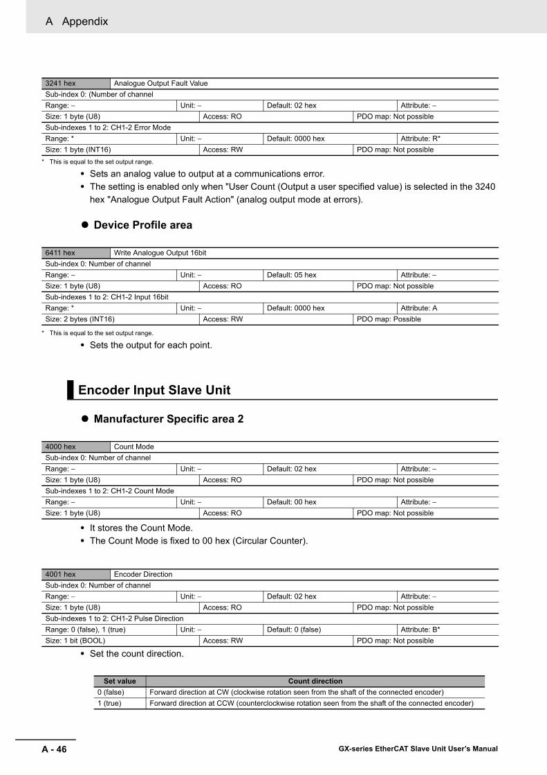
A Appendix
A - 46 GX-series EtherCAT Slave Unit User’s Manual
* This is equal to the set output range.
• Sets an analog value to output at a communications error. • The setting is enabled only when "User Count (Output a user specified value) is selected in the 3240
hex "Analogue Output Fault Action" (analog output mode at errors).
Device Profile area
* This is equal to the set output range.
• Sets the output for each point.
Manufacturer Specific area 2
• It stores the Count Mode. • The Count Mode is fixed to 00 hex (Circular Counter).
• Set the count direction.
3241 hex Analogue Output Fault ValueSub-index 0: (Number of channelRange: − Unit: − Default: 02 hex Attribute: −Size: 1 byte (U8) Access: RO PDO map: Not possibleSub-indexes 1 to 2: CH1-2 Error ModeRange: * Unit: − Default: 0000 hex Attribute: R*Size: 1 byte (INT16) Access: RW PDO map: Not possible
6411 hex Write Analogue Output 16bitSub-index 0: Number of channelRange: − Unit: − Default: 05 hex Attribute: −Size: 1 byte (U8) Access: RO PDO map: Not possibleSub-indexes 1 to 2: CH1-2 Input 16bitRange: * Unit: − Default: 0000 hex Attribute: ASize: 2 bytes (INT16) Access: RW PDO map: Possible
Encoder Input Slave Unit
4000 hex Count ModeSub-index 0: Number of channelRange: − Unit: − Default: 02 hex Attribute: −Size: 1 byte (U8) Access: RO PDO map: Not possibleSub-indexes 1 to 2: CH1-2 Count ModeRange: − Unit: − Default: 00 hex Attribute: −Size: 1 byte (U8) Access: RO PDO map: Not possible
4001 hex Encoder DirectionSub-index 0: Number of channelRange: − Unit: − Default: 02 hex Attribute: −Size: 1 byte (U8) Access: RO PDO map: Not possibleSub-indexes 1 to 2: CH1-2 Pulse DirectionRange: 0 (false), 1 (true) Unit: − Default: 0 (false) Attribute: B*Size: 1 bit (BOOL) Access: RW PDO map: Not possible
Set value Count direction0 (false) Forward direction at CW (clockwise rotation seen from the shaft of the connected encoder)1 (true) Forward direction at CCW (counterclockwise rotation seen from the shaft of the connected encoder)

A - 47
A Appendix
GX-series EtherCAT Slave Unit User’s Manual
A-1 O
bject Dictionary
A
A-1-7 M
anufacturer Specific Objects
• Set the input method.
• This object is used to specify the maximum value of the counter.• It operates as FFFFFFFF hex if 0 is set.
• The present counter value is stored.
• This object is used to specify the preset command value.
4002 hex Encoder Input SettingSub-index 0: Number of channelRange: − Unit: − Default: 02 hex Attribute: −Size: 1 byte (U8) Access: RO PDO map: Not possibleSub-indexes 1 to 2: CH1-2 Pulse Input SettingRange: 00 hex to 04 hex Unit: − Default: 02 hex Attribute: B*Size: 1 byte (U8) Access: RW PDO map: Not possible
Set value Range00 hex Phase A/B pulse (Multiplication × 1 cycle)01 hex Phase A/B pulse (Multiplication × 2 cycle)02 hex Phase A/B pulse (Multiplication × 4 cycle)03 hex Code + pulse (Multiplication × 1 cycle)04 hex Incremental/decremental pulse
4003 hex Max Count SettingSub-index 0: Number of channelRange: − Unit: − Default: 02 hex Attribute: −Size: 1 byte (U8) Access: RO PDO map: Not possibleSub-indexes 1 to 2: CH1-2 Max Count SettingRange: 00000000 hex to
FFFFFFFF hex Unit: − Default: 00000000 hex Attribute: B*
Size: 4 byte (U32) Access: RW PDO map: Not possible
4010 hex Position ValueSub-index 0: Number of channelRange: − Unit: − Default: 02 hex Attribute: −Size: 1 byte (U8) Access: RO PDO map: Not possibleSub-indexes 1 to 2: CH1-2 Position ValueRange: 00000000 hex to
FFFFFFFF hex Unit: − Default: 00000000 hex Attribute: −
Size: 4 byte (U32) Access: RO PDO map: Possible
4011 hex Preset ValueSub-index 0: Number of channelRange: − Unit: − Default: 02 hex Attribute: −Size: 1 byte (U8) Access: RO PDO map: Not possibleSub-indexes 1 to 2: CH1-2 Preset ValueRange: 00000000 hex to
FFFFFFFF hex Unit: − Default: 00000000 hex Attribute: A
Size: 4 byte (U32) Access: RW PDO map: Possible
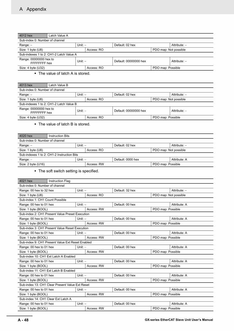
A Appendix
A - 48 GX-series EtherCAT Slave Unit User’s Manual
• The value of latch A is stored.
• The value of latch B is stored.
• The soft switch setting is specified.
4012 hex Latch Value ASub-index 0: Number of channelRange: − Unit: − Default: 02 hex Attribute: −Size: 1 byte (U8) Access: RO PDO map: Not possibleSub-indexes 1 to 2: CH1-2 Latch Value ARange: 00000000 hex to
FFFFFFFF hex Unit: − Default: 00000000 hex Attribute: −
Size: 4 byte (U32) Access: RO PDO map: Possible
4013 hex Latch Value BSub-index 0: Number of channelRange: − Unit: − Default: 02 hex Attribute: −Size: 1 byte (U8) Access: RO PDO map: Not possibleSub-indexes 1 to 2: CH1-2 Latch Value BRange: 00000000 hex to
FFFFFFFF hex Unit: − Default: 00000000 hex Attribute: −
Size: 4 byte (U32) Access: RO PDO map: Possible
4020 hex Instruction BitsSub-index 0: Number of channelRange: − Unit: − Default: 02 hex Attribute: −Size: 1 byte (U8) Access: RO PDO map: Not possibleSub-indexes 1 to 2: CH1-2 Instruction BitsRange: − Unit: − Default: 0000 hex Attribute: ASize: 2 byte (U16) Access: RW PDO map: Possible
4021 hex Instruction FlagSub-index 0: Number of channelRange: 00 hex to 32 hex Unit: − Default: 32 hex Attribute: −Size: 1 byte (U8) Access: RO PDO map: Not possibleSub-index 1: CH1 Count PossibleRange: 00 hex to 01 hex Unit: − Default: 00 hex Attribute: ASize: 1 byte (BOOL) Access: RW PDO map: PossibleSub-index 2: CH1 Present Value Preset ExecutionRange: 00 hex to 01 hex Unit: − Default: 00 hex Attribute: ASize: 1 byte (BOOL) Access: RW PDO map: PossibleSub-index 3: CH1 Present Value Reset ExecutionRange: 00 hex to 01 hex Unit: − Default: 00 hex Attribute: ASize: 1 byte (BOOL) Access: RW PDO map: PossibleSub-index 9: CH1 Present Value Ext Reset EnabledRange: 00 hex to 01 hex Unit: − Default: 00 hex Attribute: ASize: 1 byte (BOOL) Access: RW PDO map: PossibleSub-index 10: CH1 Ext Latch A EnabledRange: 00 hex to 01 hex Unit: − Default: 00 hex Attribute: ASize: 1 byte (BOOL) Access: RW PDO map: PossibleSub-index 11: CH1 Ext Latch B EnabledRange: 00 hex to 01 hex Unit: − Default: 00 hex Attribute: ASize: 1 byte (BOOL) Access: RW PDO map: PossibleSub-index 13: CH1 Clear Present Value Ext ResetRange: 00 hex to 01 hex Unit: − Default: 00 hex Attribute: ASize: 1 byte (BOOL) Access: RW PDO map: PossibleSub-index 14: CH1 Clear Ext Latch ARange: 00 hex to 01 hex Unit: − Default: 00 hex Attribute: ASize: 1 byte (BOOL) Access: RW PDO map: Possible
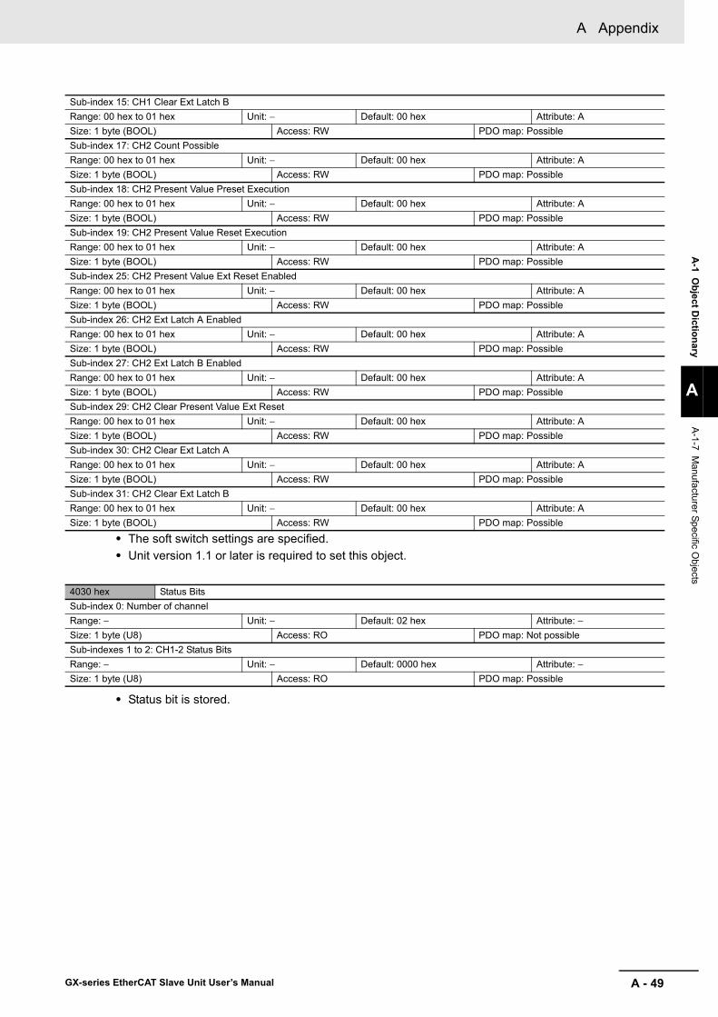
A - 49
A Appendix
GX-series EtherCAT Slave Unit User’s Manual
A-1 O
bject Dictionary
A
A-1-7 M
anufacturer Specific Objects
• The soft switch settings are specified.• Unit version 1.1 or later is required to set this object.
• Status bit is stored.
Sub-index 15: CH1 Clear Ext Latch BRange: 00 hex to 01 hex Unit: − Default: 00 hex Attribute: ASize: 1 byte (BOOL) Access: RW PDO map: PossibleSub-index 17: CH2 Count PossibleRange: 00 hex to 01 hex Unit: − Default: 00 hex Attribute: ASize: 1 byte (BOOL) Access: RW PDO map: PossibleSub-index 18: CH2 Present Value Preset ExecutionRange: 00 hex to 01 hex Unit: − Default: 00 hex Attribute: ASize: 1 byte (BOOL) Access: RW PDO map: PossibleSub-index 19: CH2 Present Value Reset ExecutionRange: 00 hex to 01 hex Unit: − Default: 00 hex Attribute: ASize: 1 byte (BOOL) Access: RW PDO map: PossibleSub-index 25: CH2 Present Value Ext Reset EnabledRange: 00 hex to 01 hex Unit: − Default: 00 hex Attribute: ASize: 1 byte (BOOL) Access: RW PDO map: PossibleSub-index 26: CH2 Ext Latch A EnabledRange: 00 hex to 01 hex Unit: − Default: 00 hex Attribute: ASize: 1 byte (BOOL) Access: RW PDO map: PossibleSub-index 27: CH2 Ext Latch B EnabledRange: 00 hex to 01 hex Unit: − Default: 00 hex Attribute: ASize: 1 byte (BOOL) Access: RW PDO map: PossibleSub-index 29: CH2 Clear Present Value Ext ResetRange: 00 hex to 01 hex Unit: − Default: 00 hex Attribute: ASize: 1 byte (BOOL) Access: RW PDO map: PossibleSub-index 30: CH2 Clear Ext Latch ARange: 00 hex to 01 hex Unit: − Default: 00 hex Attribute: ASize: 1 byte (BOOL) Access: RW PDO map: PossibleSub-index 31: CH2 Clear Ext Latch BRange: 00 hex to 01 hex Unit: − Default: 00 hex Attribute: ASize: 1 byte (BOOL) Access: RW PDO map: Possible
4030 hex Status BitsSub-index 0: Number of channelRange: − Unit: − Default: 02 hex Attribute: −Size: 1 byte (U8) Access: RO PDO map: Not possibleSub-indexes 1 to 2: CH1-2 Status BitsRange: − Unit: − Default: 0000 hex Attribute: −Size: 1 byte (U8) Access: RO PDO map: Possible

A Appendix
A - 50 GX-series EtherCAT Slave Unit User’s Manual
• The status bits are stored.• Unit version 1.1 or later is required to set this object.
4031 hex Status FlagSub-index 0: Number of channelRange: 00 hex to 16 hex Unit: − Default: 16 hex Attribute: −Size: 1 byte (U8) Access: RO PDO map: Not possibleSub-index 1: CH1 Present Value Preset Execution CompletedRange: 00 hex to 01 hex Unit: − Default: 00 hex Attribute: ASize: 1 byte (BOOL) Access: RW PDO map: PossibleSub-index 2: CH1 Present Value Reset Execution CompletedRange: 00 hex to 01 hex Unit: − Default: 00 hex Attribute: ASize: 1 byte (BOOL) Access: RW PDO map: PossibleSub-index 3: CH1 Ext Reset FlagRange: 00 hex to 01 hex Unit: − Default: 00 hex Attribute: ASize: 1 byte (BOOL) Access: RW PDO map: PossibleSub-index 4: CH1 Ext Latch A FlagRange: 00 hex to 01 hex Unit: − Default: 00 hex Attribute: ASize: 1 byte (BOOL) Access: RW PDO map: PossibleSub-index 5: CH1 Ext Latch B FlagRange: 00 hex to 01 hex Unit: − Default: 00 hex Attribute: ASize: 1 byte (BOOL) Access: RW PDO map: PossibleSub-index 7: CH1 Present Value Preset Set Value ErrorRange: 00 hex to 01 hex Unit: − Default: 00 hex Attribute: ASize: 1 byte (BOOL) Access: RW PDO map: PossibleSub-index 8: CH1 Counter Operation StateRange: 00 hex to 01 hex Unit: − Default: 00 hex Attribute: ASize: 1 byte (BOOL) Access: RW PDO map: PossibleSub-index 9: CH2 Present Value Preset Execution CompletedRange: 00 hex to 01 hex Unit: − Default: 00 hex Attribute: ASize: 1 byte (BOOL) Access: RW PDO map: PossibleSub-index 10: CH2 Present Value Reset Execution CompletedRange: 00 hex to 01 hex Unit: − Default: 00 hex Attribute: ASize: 1 byte (BOOL) Access: RW PDO map: PossibleSub-index 11: CH2 Ext Reset FlagRange: 00 hex to 01 hex Unit: − Default: 00 hex Attribute: ASize: 1 byte (BOOL) Access: RW PDO map: PossibleSub-index 12: CH2 Ext Latch A FlagRange: 00 hex to 01 hex Unit: − Default: 00 hex Attribute: ASize: 1 byte (BOOL) Access: RW PDO map: PossibleSub-index 13: CH2 Ext Latch B FlagRange: 00 hex to 01 hex Unit: − Default: 00 hex Attribute: ASize: 1 byte (BOOL) Access: RW PDO map: PossibleSub-index 15: CH2 Present Value Preset Set Value ErrorRange: 00 hex to 01 hex Unit: − Default: 00 hex Attribute: ASize: 1 byte (BOOL) Access: RW PDO map: PossibleSub-index 16: CH2 Counter Operation StateRange: 00 hex to 01 hex Unit: − Default: 00 hex Attribute: ASize: 1 byte (BOOL) Access: RW PDO map: Possible
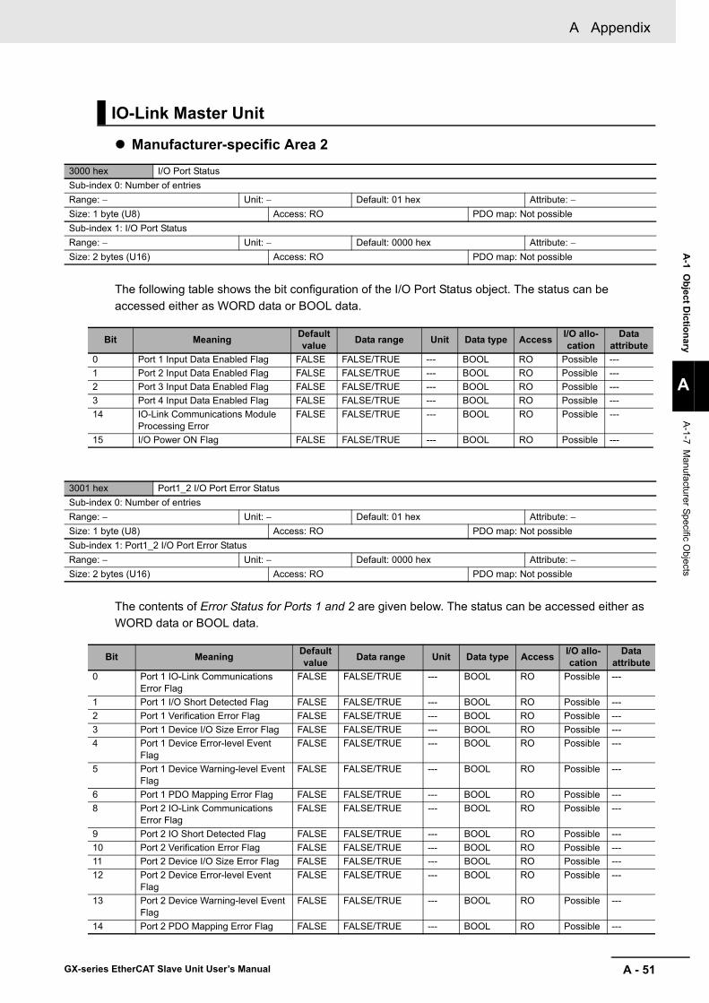
A - 51
A Appendix
GX-series EtherCAT Slave Unit User’s Manual
A-1 O
bject Dictionary
A
A-1-7 M
anufacturer Specific Objects
Manufacturer-specific Area 2
The following table shows the bit configuration of the I/O Port Status object. The status can be accessed either as WORD data or BOOL data.
The contents of Error Status for Ports 1 and 2 are given below. The status can be accessed either as WORD data or BOOL data.
IO-Link Master Unit
3000 hex I/O Port StatusSub-index 0: Number of entriesRange: − Unit: − Default: 01 hex Attribute: −Size: 1 byte (U8) Access: RO PDO map: Not possibleSub-index 1: I/O Port StatusRange: − Unit: − Default: 0000 hex Attribute: −Size: 2 bytes (U16) Access: RO PDO map: Not possible
3001 hex Port1_2 I/O Port Error StatusSub-index 0: Number of entriesRange: − Unit: − Default: 01 hex Attribute: −Size: 1 byte (U8) Access: RO PDO map: Not possibleSub-index 1: Port1_2 I/O Port Error StatusRange: − Unit: − Default: 0000 hex Attribute: −Size: 2 bytes (U16) Access: RO PDO map: Not possible
Bit Meaning Default value Data range Unit Data type Access I/O allo-
cationData
attribute0 Port 1 Input Data Enabled Flag FALSE FALSE/TRUE --- BOOL RO Possible ---1 Port 2 Input Data Enabled Flag FALSE FALSE/TRUE --- BOOL RO Possible ---2 Port 3 Input Data Enabled Flag FALSE FALSE/TRUE --- BOOL RO Possible ---3 Port 4 Input Data Enabled Flag FALSE FALSE/TRUE --- BOOL RO Possible ---14 IO-Link Communications Module
Processing ErrorFALSE FALSE/TRUE --- BOOL RO Possible ---
15 I/O Power ON Flag FALSE FALSE/TRUE --- BOOL RO Possible ---
Bit Meaning Default value Data range Unit Data type Access I/O allo-
cationData
attribute0 Port 1 IO-Link Communications
Error FlagFALSE FALSE/TRUE --- BOOL RO Possible ---
1 Port 1 I/O Short Detected Flag FALSE FALSE/TRUE --- BOOL RO Possible ---2 Port 1 Verification Error Flag FALSE FALSE/TRUE --- BOOL RO Possible ---3 Port 1 Device I/O Size Error Flag FALSE FALSE/TRUE --- BOOL RO Possible ---4 Port 1 Device Error-level Event
FlagFALSE FALSE/TRUE --- BOOL RO Possible ---
5 Port 1 Device Warning-level Event Flag
FALSE FALSE/TRUE --- BOOL RO Possible ---
6 Port 1 PDO Mapping Error Flag FALSE FALSE/TRUE --- BOOL RO Possible ---8 Port 2 IO-Link Communications
Error FlagFALSE FALSE/TRUE --- BOOL RO Possible ---
9 Port 2 IO Short Detected Flag FALSE FALSE/TRUE --- BOOL RO Possible ---10 Port 2 Verification Error Flag FALSE FALSE/TRUE --- BOOL RO Possible ---11 Port 2 Device I/O Size Error Flag FALSE FALSE/TRUE --- BOOL RO Possible ---12 Port 2 Device Error-level Event
FlagFALSE FALSE/TRUE --- BOOL RO Possible ---
13 Port 2 Device Warning-level Event Flag
FALSE FALSE/TRUE --- BOOL RO Possible ---
14 Port 2 PDO Mapping Error Flag FALSE FALSE/TRUE --- BOOL RO Possible ---

A Appendix
A - 52 GX-series EtherCAT Slave Unit User’s Manual
The contents of Error Status for Ports 3 and 4 are given below. The status can be accessed either as WORD data or BOOL data.
3002 hex Port3_4 I/O Port Error StatusSub-index 0: Number of entriesRange: − Unit: − Default: 01 hex Attribute: −Size: 1 byte (U8) Access: RO PDO map: Not possibleSub-index 1: Port3_4 I/O Port Error StatusRange: − Unit: − Default: 0000 hex Attribute: −Size: 2 bytes (U16) Access: RO PDO map: Not possible
3003 hex Port5_6 I/O Port Error StatusSub-index 0: Number of entriesRange: − Unit: − Default: 01 hex Attribute: −Size: 1 byte (U8) Access: RO PDO map: Not possibleSub-index 1: Port5_6 I/O Port Error StatusRange: − Unit: − Default: 0000 hex Attribute: −Size: 2 bytes (U16) Access: RO PDO map: Not possible
Bit Meaning Default value Data range Unit Data type Access I/O allo-
cationData
attribute0 Port 3 IO-Link Communications
Error FlagFALSE FALSE/TRUE --- BOOL RO Possible ---
1 Port 3 IO Short Detected Flag FALSE FALSE/TRUE --- BOOL RO Possible ---2 Port 3 Verification Error Flag FALSE FALSE/TRUE --- BOOL RO Possible ---3 Port 3 Device I/O Size Error Flag FALSE FALSE/TRUE --- BOOL RO Possible ---4 Port 3 Device Error-level Event
FlagFALSE FALSE/TRUE --- BOOL RO Possible ---
5 Port 3 Device Warning-level Event Flag
FALSE FALSE/TRUE --- BOOL RO Possible ---
6 Port 3 PDO Mapping Error Flag FALSE FALSE/TRUE --- BOOL RO Possible ---8 Port 4 IO-Link Communications
Error FlagFALSE FALSE/TRUE --- BOOL RO Possible ---
9 Port 4 IO Short Detected Flag FALSE FALSE/TRUE --- BOOL RO Possible ---10 Port 4 Verification Error Flag FALSE FALSE/TRUE --- BOOL RO Possible ---11 Port 4 Device I/O Size Error Flag FALSE FALSE/TRUE --- BOOL RO Possible ---12 Port 4 Device Error-level Event
FlagFALSE FALSE/TRUE --- BOOL RO Possible ---
13 Port 4 Device Warning-level Event Flag
FALSE FALSE/TRUE --- BOOL RO Possible ---
14 Port 4 PDO Mapping Error Flag FALSE FALSE/TRUE --- BOOL RO Possible ---

A - 53
A Appendix
GX-series EtherCAT Slave Unit User’s Manual
A-1 O
bject Dictionary
A
A-1-7 M
anufacturer Specific Objects
The contents of Error Status for Ports 5 and 6 are given below. The status can be accessed either as WORD data or BOOL data.
The contents of Error Status for Ports 7 and 8 are given below. The status can be accessed either as WORD data or BOOL data.
3004 hex Port7_8 I/O Port Error StatusSub-index 0: Number of entriesRange: − Unit: − Default: 01 hex Attribute: −Size: 1 byte (U8) Access: RO PDO map: Not possibleSub-index 1: Port7_8 I/O Port Error StatusRange: − Unit: − Default: 0000 hex Attribute: −Size: 2 bytes (U16) Access: RO PDO map: Not possible
Bit Meaning Default value Data range Unit Data type Access I/O allo-
cationData
attribute0 Port 5 IO-Link Communications
Error FlagFALSE FALSE/TRUE --- BOOL RO Possible ---
1 Port 5 IO Short Detected Flag FALSE FALSE/TRUE --- BOOL RO Possible ---2 Port 5 Verification Error Flag FALSE FALSE/TRUE --- BOOL RO Possible ---3 Port 5 Device I/O Size Error Flag FALSE FALSE/TRUE --- BOOL RO Possible ---4 Port 5 Device Error-level Event
FlagFALSE FALSE/TRUE --- BOOL RO Possible ---
5 Port 5 Device Warning-level Event Flag
FALSE FALSE/TRUE --- BOOL RO Possible ---
6 Port 5 PDO Mapping Error Flag FALSE FALSE/TRUE --- BOOL RO Possible ---8 Port 6 IO-Link Communications
Error FlagFALSE FALSE/TRUE --- BOOL RO Possible ---
9 Port 6 IO Short Detected Flag FALSE FALSE/TRUE --- BOOL RO Possible ---10 Port 6 Verification Error Flag FALSE FALSE/TRUE --- BOOL RO Possible ---11 Port 6 Device I/O Size Error Flag FALSE FALSE/TRUE --- BOOL RO Possible ---12 Port 6 Device Error-level Event
FlagFALSE FALSE/TRUE --- BOOL RO Possible ---
13 Port 6 Device Warning-level Event Flag
FALSE FALSE/TRUE --- BOOL RO Possible ---
14 Port 6 PDO Mapping Error Flag FALSE FALSE/TRUE --- BOOL RO Possible ---
Bit Meaning Default value Data range Unit Data type Access I/O allo-
cationData
attribute0 Port 7 IO-Link Communications
Error FlagFALSE FALSE/TRUE --- BOOL RO Possible ---
1 Port 7 IO Short Detected Flag FALSE FALSE/TRUE --- BOOL RO Possible ---2 Port 7 Verification Error Flag FALSE FALSE/TRUE --- BOOL RO Possible ---3 Port 7 Device I/O Size Error Flag FALSE FALSE/TRUE --- BOOL RO Possible ---4 Port 7 Device Error-level Event
FlagFALSE FALSE/TRUE --- BOOL RO Possible ---
5 Port 7 Device Warning-level Event Flag
FALSE FALSE/TRUE --- BOOL RO Possible ---
6 Port 7 PDO Mapping Error Flag FALSE FALSE/TRUE --- BOOL RO Possible ---8 Port 8 IO-Link Communications
Error FlagFALSE FALSE/TRUE --- BOOL RO Possible ---
9 Port 8 IO Short Detected Flag FALSE FALSE/TRUE --- BOOL RO Possible ---10 Port 8 Verification Error Flag FALSE FALSE/TRUE --- BOOL RO Possible ---11 Port 8 Device I/O Size Error Flag FALSE FALSE/TRUE --- BOOL RO Possible ---12 Port 8 Device Error-level Event
FlagFALSE FALSE/TRUE --- BOOL RO Possible ---
13 Port 8 Device Warning-level Event Flag
FALSE FALSE/TRUE --- BOOL RO Possible ---
14 Port 8 PDO Mapping Error Flag FALSE FALSE/TRUE --- BOOL RO Possible ---

A Appendix
A - 54 GX-series EtherCAT Slave Unit User’s Manual
The following table shows the bit configuration of the Digital Input Data object. The status can be accessed either as WORD data or BOOL data.
The following table shows the bit configuration of the Digital Output Data object. The status can be accessed either as WORD data or BOOL data.
3005 hex Digital Input DataSub-index 0: Number of entriesRange: − Unit: − Default: 01 hex Attribute: −Size: 1 byte (U8) Access: RO PDO map: Not possibleSub-index 1: Digital Input DataRange: − Unit: − Default: 0000 hex Attribute: −Size: 2 bytes (U16) Access: RO PDO map: Not possible
3100 hex Digital Output DataSub-index 0: Number of entriesRange: − Unit: − Default: 01 hex Attribute: −Size: 1 byte (U8) Access: RO PDO map: Not possibleSub-index 1: Digital Output DataRange: − Unit: − Default: 0000 hex Attribute: ASize: 2 bytes (U16) Access: RW PDO map: Possible
Bit Meaning Default value Data range Unit Data
type Access I/O alloca-tion
Data attribute
1 Port 1 Digital Input Bit FALSE FALSE/TRUE --- BOOL RO Possible ---2 Port 2 Digital Input Bit FALSE FALSE/TRUE --- BOOL RO Possible ---3 Port 3 Digital Input Bit FALSE FALSE/TRUE --- BOOL RO Possible ---4 Port 4 Digital Input Bit FALSE FALSE/TRUE --- BOOL RO Possible ---
Bit Meaning Default value Data range Unit Data type Access I/O allo-
cationData
attribute1 Port 1 Digital Output Bit FALSE FALSE/TRUE --- BOOL RO Possible ---2 Port 2 Digital Output Bit FALSE FALSE/TRUE --- BOOL RO Possible ---3 Port 3 Digital Output Bit FALSE FALSE/TRUE --- BOOL RO Possible ---4 Port 4 Digital Output Bit FALSE FALSE/TRUE --- BOOL RO Possible ---
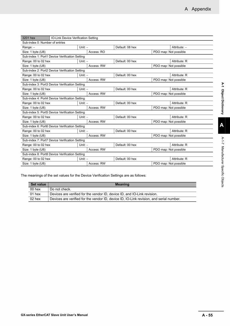
A - 55
A Appendix
GX-series EtherCAT Slave Unit User’s Manual
A-1 O
bject Dictionary
A
A-1-7 M
anufacturer Specific Objects
The meanings of the set values for the Device Verification Settings are as follows:
3201 hex IO-Link Device Verification SettingSub-index 0: Number of entriesRange: − Unit: − Default: 08 hex Attribute: −Size: 1 byte (U8) Access: RO PDO map: Not possibleSub-index 1: Port1 Device Verification SettingRange: 00 to 02 hex Unit: − Default: 00 hex Attribute: RSize: 1 byte (U8) Access: RW PDO map: Not possibleSub-index 2: Port2 Device Verification SettingRange: 00 to 02 hex Unit: − Default: 00 hex Attribute: RSize: 1 byte (U8) Access: RW PDO map: Not possibleSub-index 3: Port3 Device Verification SettingRange: 00 to 02 hex Unit: − Default: 00 hex Attribute: RSize: 1 byte (U8) Access: RW PDO map: Not possibleSub-index 4: Port4 Device Verification SettingRange: 00 to 02 hex Unit: − Default: 00 hex Attribute: RSize: 1 byte (U8) Access: RW PDO map: Not possibleSub-index 5: Port5 Device Verification SettingRange: 00 to 02 hex Unit: − Default: 00 hex Attribute: RSize: 1 byte (U8) Access: RW PDO map: Not possibleSub-index 6: Port6 Device Verification SettingRange: 00 to 02 hex Unit: − Default: 00 hex Attribute: RSize: 1 byte (U8) Access: RW PDO map: Not possibleSub-index 7: Port7 Device Verification SettingRange: 00 to 02 hex Unit: − Default: 00 hex Attribute: RSize: 1 byte (U8) Access: RW PDO map: Not possibleSub-index 8: Port8 Device Verification SettingRange: 00 to 02 hex Unit: − Default: 00 hex Attribute: RSize: 1 byte (U8) Access: RW PDO map: Not possible
Set value Meaning00 hex Do not check.01 hex Devices are verified for the vendor ID, device ID, and IO-Link revision.02 hex Devices are verified for the vendor ID, device ID, IO-Link revision, and serial number.

A Appendix
A - 56 GX-series EtherCAT Slave Unit User’s Manual
The meanings of the set values for the Backup Settings are as follows:
3202 hex Backup SettingSub-index 0: Number of entriesRange: − Unit: − Default: 08 hex Attribute: −Size: 1 byte (U8) Access: RO PDO map: Not possibleSub-index 1: Port1 Backup SettingRange: 00 hex or 01 hex Unit: − Default: 00 hex Attribute: RSize: 1 byte (U8) Access: RW PDO map: Not possibleSub-index 2: Port2 Backup SettingRange: 00 hex or 01 hex Unit: − Default: 00 hex Attribute: RSize: 1 byte (U8) Access: RW PDO map: Not possibleSub-index 3: Port3 Backup SettingRange: 00 hex or 01 hex Unit: − Default: 00 hex Attribute: RSize: 1 byte (U8) Access: RW PDO map: Not possibleSub-index 4: Port4 Backup SettingRange: 00 hex or 01 hex Unit: − Default: 00 hex Attribute: RSize: 1 byte (U8) Access: RW PDO map: Not possibleSub-index 5: Port5 Backup SettingRange: 00 hex or 01 hex Unit: − Default: 00 hex Attribute: RSize: 1 byte (U8) Access: RW PDO map: Not possibleSub-index 6: Port6 Backup SettingRange: 00 hex or 01 hex Unit: − Default: 00 hex Attribute: RSize: 1 byte (U8) Access: RW PDO map: Not possibleSub-index 7: Port7 Backup SettingRange: 00 hex or 01 hex Unit: − Default: 00 hex Attribute: RSize: 1 byte (U8) Access: RW PDO map: Not possibleSub-index 8: Port8 Backup SettingRange: 00 hex or 01 hex Unit: − Default: 00 hex Attribute: RSize: 1 byte (U8) Access: RW PDO map: Not possible
Set value Meaning00 hex The backup functions are disabled.01 hex The backup functions are enabled.

A - 57
A Appendix
GX-series EtherCAT Slave Unit User’s Manual
A-1 O
bject Dictionary
A
A-1-7 M
anufacturer Specific Objects
The meanings of the set values for the Restoration Settings are as follows:
3203 hex Restore SettingSub-index 0: Number of entriesRange: − Unit: − Default: 08 hex Attribute: −Size: 1 byte (U8) Access: RO PDO map: Not possibleSub-index 1: Port1 Restore SettingRange: 00 hex or 01 hex Unit: − Default: 00 hex Attribute: RSize: 1 byte (U8) Access: RW PDO map: Not possibleSub-index 2: Port2 Restore SettingRange: 00 hex or 01 hex Unit: − Default: 00 hex Attribute: RSize: 1 byte (U8) Access: RW PDO map: Not possibleSub-index 3: Port3 Restore SettingRange: 00 hex or 01 hex Unit: − Default: 00 hex Attribute: RSize: 1 byte (U8) Access: RW PDO map: Not possibleSub-index 4: Port5 Restore SettingRange: 00 hex or 01 hex Unit: − Default: 00 hex Attribute: RSize: 1 byte (U8) Access: RW PDO map: Not possibleSub-index 5: Port5 Restore SettingRange: 00 hex or 01 hex Unit: − Default: 00 hex Attribute: RSize: 1 byte (U8) Access: RW PDO map: Not possibleSub-index 6: Port6 Restore SettingRange: 00 hex or 01 hex Unit: − Default: 00 hex Attribute: RSize: 1 byte (U8) Access: RW PDO map: Not possibleSub-index 7: Port7 Restore SettingRange: 00 hex or 01 hex Unit: − Default: 00 hex Attribute: RSize: 1 byte (U8) Access: RW PDO map: Not possibleSub-index 8: Port8 Restore SettingRange: 00 hex or 01 hex Unit: − Default: 00 hex Attribute: RSize: 1 byte (U8) Access: RW PDO map: Not possible
Set value Meaning00 hex Restoration is disabled.01 hex Restoration is enabled.

A Appendix
A - 58 GX-series EtherCAT Slave Unit User’s Manual
The Load Regection Output Settings are used to set the load rejection outputs to use when controllercommunications errors occur. The meanings of the set values are as follows::
3204 hex Load Rejection Output SettingSub-index 0: Number of entriesRange: − Unit: − Default: 08 hex Attribute: −Size: 1 byte (U8) Access: RO PDO map: Not possibleSub-index 1: Port1 Load Rejection Output SettingRange: 00 hex or 01 hex Unit: − Default: 00 hex Attribute: RSize: 1 byte (U8) Access: RW PDO map: Not possibleSub-index 2: Port2 Load Rejection Output SettingRange: 00 hex or 01 hex Unit: − Default: 00 hex Attribute: RSize: 1 byte (U8) Access: RW PDO map: Not possibleSub-index 3: Port3 Load Rejection Output SettingRange: 00 hex or 01 hex Unit: − Default: 00 hex Attribute: RSize: 1 byte (U8) Access: RW PDO map: Not possibleSub-index 4: Port4 Load Rejection Output SettingRange: 00 hex or 01 hex Unit: − Default: 00 hex Attribute: RSize: 1 byte (U8) Access: RW PDO map: Not possibleSub-index 5: Port5 Load Rejection Output SettingRange: 00 hex or 01 hex Unit: − Default: 00 hex Attribute: RSize: 1 byte (U8) Access: RW PDO map: Not possibleSub-index 6: Port6 Load Rejection Output SettingRange: 00 hex or 01 hex Unit: − Default: 00 hex Attribute: RSize: 1 byte (U8) Access: RW PDO map: Not possibleSub-index 7: Port7 Load Rejection Output SettingRange: 00 hex or 01 hex Unit: − Default: 00 hex Attribute: RSize: 1 byte (U8) Access: RW PDO map: Not possibleSub-index 8: Port8 Load Rejection Output SettingRange: 00 hex or 01 hex Unit: − Default: 00 hex Attribute: RSize: 1 byte (U8) Access: RW PDO map: Not possible
Set value Meaning00 hex IO-Link Mode
Enabled: Output rejection notification is sent to the IO-Link device.
SIO (DO) Mode
Enabled: The output value is cleared to OFF.01 hex Backup failed.
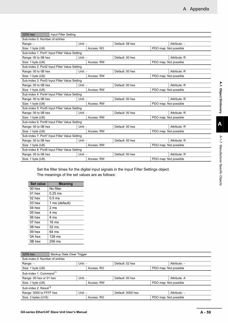
A - 59
A Appendix
GX-series EtherCAT Slave Unit User’s Manual
A-1 O
bject Dictionary
A
A-1-7 M
anufacturer Specific Objects
Set the filter times for the digital input signals in the Input Filter Settings object.The meanings of the set values are as follows:
3205 hex Input Filter SettingSub-index 0: Number of entriesRange: − Unit: − Default: 08 hex Attribute: −Size: 1 byte (U8) Access: RO PDO map: Not possibleSub-index 1: Port1 Input Filter Value SettingRange: 00 to 0B hex Unit: − Default: 00 hex Attribute: RSize: 1 byte (U8) Access: RW PDO map: Not possibleSub-index 2: Port2 Input Filter Value SettingRange: 00 to 0B hex Unit: − Default: 00 hex Attribute: RSize: 1 byte (U8) Access: RW PDO map: Not possibleSub-index 3: Port3 Input Filter Value SettingRange: 00 to 0B hex Unit: − Default: 00 hex Attribute: RSize: 1 byte (U8) Access: RW PDO map: Not possibleSub-index 4: Port4 Input Filter Value SettingRange: 00 to 0B hex Unit: − Default: 00 hex Attribute: RSize: 1 byte (U8) Access: RW PDO map: Not possibleSub-index 5: Port5 Input Filter Value SettingRange: 00 to 0B hex Unit: − Default: 00 hex Attribute: RSize: 1 byte (U8) Access: RW PDO map: Not possibleSub-index 6: Port6 Input Filter Value SettingRange: 00 to 0B hex Unit: − Default: 00 hex Attribute: RSize: 1 byte (U8) Access: RW PDO map: Not possibleSub-index 7: Port7 Input Filter Value SettingRange: 00 to 0B hex Unit: − Default: 00 hex Attribute: RSize: 1 byte (U8) Access: RW PDO map: Not possibleSub-index 8: Port8 Input Filter Value SettingRange: 00 to 0B hex Unit: − Default: 00 hex Attribute: RSize: 1 byte (U8) Access: RW PDO map: Not possible
3209 hex Backup Data Clear TriggerSub-index 0: Number of entriesRange: − Unit: − Default: 02 hex Attribute: −Size: 1 byte (U8) Access: RO PDO map: Not possible
Sub-index 1: Command*1
Range: 00 hex or 01 hex Unit: − Default: 00 hex Attribute: ASize: 1 byte (U8) Access: RW PDO map: Not possible
Sub-index 2: Result*2
Range: 0000 to FFFF hex Unit: − Default: 0000 hex Attribute: −Size: 2 bytes (U16) Access: RO PDO map: Not possible
Set value Meaning00 hex No filter01 hex 0.25 ms02 hex 0.5 ms03 hex 1 ms (default)04 hex 2 ms05 hex 4 ms06 hex 8 ms07 hex 16 ms08 hex 32 ms09 hex 64 ms0A hex 128 ms0B hex 256 ms
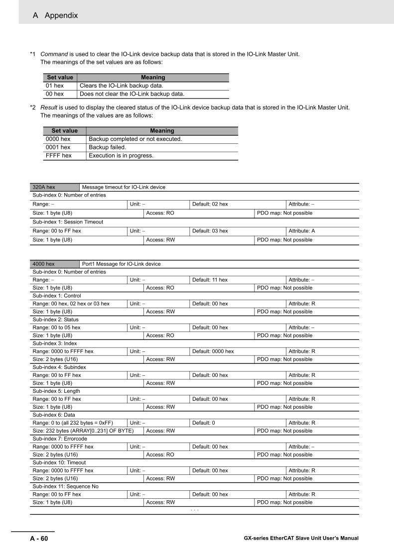
A Appendix
A - 60 GX-series EtherCAT Slave Unit User’s Manual
*1 Command is used to clear the IO-Link device backup data that is stored in the IO-Link Master Unit.The meanings of the set values are as follows:
*2 Result is used to display the cleared status of the IO-Link device backup data that is stored in the IO-Link Master Unit.The meanings of the values are as follows:
320A hex Message timeout for IO-Link deviceSub-index 0: Number of entries
Range: − Unit: − Default: 02 hex Attribute: −
Size: 1 byte (U8) Access: RO PDO map: Not possible
Sub-index 1: Session Timeout
Range: 00 to FF hex Unit: − Default: 03 hex Attribute: A
Size: 1 byte (U8) Access: RW PDO map: Not possible
4000 hex Port1 Message for IO-Link deviceSub-index 0: Number of entriesRange: − Unit: − Default: 11 hex Attribute: −Size: 1 byte (U8) Access: RO PDO map: Not possibleSub-index 1: ControlRange: 00 hex, 02 hex or 03 hex Unit: − Default: 00 hex Attribute: RSize: 1 byte (U8) Access: RW PDO map: Not possibleSub-index 2: StatusRange: 00 to 05 hex Unit: − Default: 00 hex Attribute: −Size: 1 byte (U8) Access: RO PDO map: Not possibleSub-index 3: IndexRange: 0000 to FFFF hex Unit: − Default: 0000 hex Attribute: RSize: 2 bytes (U16) Access: RW PDO map: Not possibleSub-index 4: SubindexRange: 00 to FF hex Unit: − Default: 00 hex Attribute: RSize: 1 byte (U8) Access: RW PDO map: Not possibleSub-index 5: LengthRange: 00 to FF hex Unit: − Default: 00 hex Attribute: RSize: 1 byte (U8) Access: RW PDO map: Not possibleSub-index 6: DataRange: 0 to (all 232 bytes = 0xFF) Unit: − Default: 0 Attribute: RSize: 232 bytes (ARRAY[0..231] OF BYTE) Access: RW PDO map: Not possibleSub-index 7: ErrorcodeRange: 0000 to FFFF hex Unit: − Default: 00 hex Attribute: −Size: 2 bytes (U16) Access: RO PDO map: Not possibleSub-index 10: TimeoutRange: 0000 to FFFF hex Unit: − Default: 00 hex Attribute: RSize: 2 bytes (U16) Access: RW PDO map: Not possibleSub-index 11: Sequence NoRange: 00 to FF hex Unit: − Default: 00 hex Attribute: RSize: 1 byte (U8) Access: RW PDO map: Not possible
· · ·
Set value Meaning01 hex Clears the IO-Link backup data.00 hex Does not clear the IO-Link backup data.
Set value Meaning0000 hex Backup completed or not executed.0001 hex Backup failed.FFFF hex Execution is in progress.
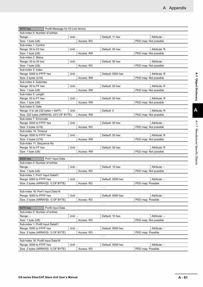
A - 61
A Appendix
GX-series EtherCAT Slave Unit User’s Manual
A-1 O
bject Dictionary
A
A-1-7 M
anufacturer Specific Objects
4070 hex Port8 Message for IO-Link deviceSub-index 0: Number of entriesRange: − Unit: − Default: 11 hex Attribute: −Size: 1 byte (U8) Access: RO PDO map: Not possibleSub-index 1: ControlRange: 00 to 03 hex Unit: − Default: 00 hex Attribute: RSize: 1 byte (U8) Access: RW PDO map: Not possibleSub-index 2: StatusRange: 00 to 05 hex Unit: − Default: 00 hex Attribute: −Size: 1 byte (U8) Access: RO PDO map: Not possibleSub-index 3: IndexRange: 0000 to FFFF hex Unit: − Default: 0000 hex Attribute: RSize: 2 bytes (U16) Access: RW PDO map: Not possibleSub-index 4: SubindexRange: 00 to FF hex Unit: − Default: 00 hex Attribute: RSize: 1 byte (U8) Access: RW PDO map: Not possibleSub-index 5: LengthRange: 00 to FF hex Unit: − Default: 00 hex Attribute: RSize: 1 byte (U8) Access: RW PDO map: Not possibleSub-index 6: DataRange: 0 to (all 232 bytes = 0xFF) Unit: − Default: 0 Attribute: RSize: 232 bytes (ARRAY[0..231] OF BYTE) Access: RW PDO map: Not possibleSub-index 7: ErrorcodeRange: 0000 to FFFF hex Unit: − Default: 00 hex Attribute: −Size: 2 bytes (U16) Access: RO PDO map: Not possibleSub-index 10: TimeoutRange: 0000 to FFFF hex Unit: − Default: 00 hex Attribute: RSize: 2 bytes (U16) Access: RW PDO map: Not possibleSub-index 11: Sequence NoRange: 00 to FF hex Unit: − Default: 00 hex Attribute: RSize: 1 byte (U8) Access: RW PDO map: Not possible
6000 hex Port1 Input DataSub-index 0: Number of entriesRange: − Unit: − Default: 10 hex Attribute: −Size: 1 byte (U8) Access: RO PDO map: Not possibleSub-index 1: Port1 Input Data01Range: 0000 to FFFF hex Unit: − Default: 0000 hex Attribute: −Size: 2 bytes (ARRAY[0..1] OF BYTE) Access: RO PDO map: Possible
· · ·Sub-index 16: Port1 Input Data16Range: 0000 to FFFF hex Unit: − Default: 0000 hex Attribute: −Size: 2 bytes (ARRAY[0..1] OF BYTE) Access: RO PDO map: Possible
· · ·6070 hex Port8 Input DataSub-index 0: Number of entriesRange: − Unit: − Default: 10 hex Attribute: −Size: 1 byte (U8) Access: RO PDO map: Not possibleSub-index 1: Port8 Input Data01Range: 0000 to FFFF hex Unit: − Default: 0000 hex Attribute: −Size: 2 bytes (ARRAY[0..1] OF BYTE) Access: RO PDO map: Possible
· · ·Sub-index 16: Port8 Input Data16Range: 0000 to FFFF hex Unit: − Default: 0000 hex Attribute: −Size: 2 bytes (ARRAY[0..1] OF BYTE) Access: RO PDO map: Possible

A Appendix
A - 62 GX-series EtherCAT Slave Unit User’s Manual
7000 hex Port1 Output DataSub-index 0: Number of entriesRange: − Unit: − Default: 10 hex Attribute: −Size: 1 byte (U8) Access: RO PDO map: Not possibleSub-index 1: Port1 Output Data01Range: 0000 to FFFF hex Unit: − Default: 0000 hex Attribute: −Size: 2 bytes (ARRAY[0..1] OF BYTE) Access: RW PDO map: Possible
· · ·Sub-index 16: Port1 Output Data16Range: 0000 to FFFF hex Unit: − Default: 0000 hex Attribute: −Size: 2 bytes (ARRAY[0..1] OF BYTE) Access: RW PDO map: Possible
· · ·7070 hex Port8 Output DataSub-index 0: Number of entriesRange: − Unit: − Default: 10 hex Attribute: −Size: 1 byte (ARRAY[0..1] OF BYTE) Access: RO PDO map: Not possibleSub-index 1: Port8 Output Data01Range: 0000 to FFFF hex Unit: − Default: 0000 hex Attribute: −Size: 2 bytes (ARRAY[0..1] OF BYTE) Access: RW PDO map: Possible
· · ·Sub-index 16: Port8 Output Data16Range: 0000 to FFFF hex Unit: − Default: 0000 hex Attribute: −Size: 2 bytes (ARRAY[0..1] OF BYTE) Access: RW PDO map: Possible

A - 63
A Appendix
GX-series EtherCAT Slave Unit User’s Manual
A-1 O
bject Dictionary
A
A-1-7 M
anufacturer Specific Objects
*1 The communications mode for each port is set in Master Control Communications Mode Settings.The meanings of the set values are as follows:
8000 hex Port1 IO-Link Device Configuration DataSub-index 0: Number of entriesRange: − Unit: − Default: 28 hex Attribute: −Size: 1 byte (U8) Access: RO PDO map: Not possibleSub-index 4: Device IDRange: 00000000 to 00FFFFFF hex Unit: − Default: 00000000 hex Attribute: RSize: 4 bytes (U32) Access: RW PDO map: Not possibleSub-index 5: Vendor IDRange: 00000000 to 0000FFFF hex Unit: − Default: 00000000 hex Attribute: RSize: 4 bytes (U32) Access: RW PDO map: Not possibleSub-index 20: IO-Link RevisionRange: 00 to FF hex Unit: − Default: 00 hex Attribute: RSize: 1 byte (U8) Access: RW PDO map: Not possibleSub-index 24: Process Data In LengthRange: 00 to 20 hex Unit: − Default: 02 hex Attribute: RSize: 1 byte (U8) Access: RW PDO map: Not possibleSub-index 25: Process Data Out LengthRange: 00 to 20 hex Unit: − Default: 02 hex Attribute: RSize: 1 byte (U8) Access: RW PDO map: Not possibleSub-index 28: Master Control Note: Set the communications mode.Range: 00 to 03 hex Unit: − Default: 03 hex*1 Attribute: R
Size: 1 byte (U8) Access: RW PDO map: Not possible· · ·
8070 hex Port8 IO-Link Device Configuration DataSub-index 0: Number of entriesRange: − Unit: − Default: 28 hex Attribute: −Size: 1 byte (U8) Access: RO PDO map: Not possibleSub-index 4: Device IDRange: 00000000 to 00FFFFFF hex Unit: − Default: 00000000 hex Attribute: RSize: 4 bytes (U32) Access: RW PDO map: Not possibleSub-index 5: Vendor IDRange: 00000000 to 0000FFFF hex Unit: − Default: 00000000 hex Attribute: RSize: 4 bytes (U32) Access: RW PDO map: Not possibleSub-index 20: IO-Link RevisionRange: 00 to FF hex Unit: − Default: 00 hex Attribute: RSize: 1 byte (U8) Access: RW PDO map: Not possibleSub-index 24: Process Data In LengthRange: 00 to 20 hex Unit: − Default: 02 hex Attribute: RSize: 1 byte (U8) Access: RW PDO map: Not possibleSub-index 25: Process Data Out LengthRange: 00 to 20 hex Unit: − Default: 02 hex Attribute: RSize: 1 byte (U8) Access: RW PDO map: Not possibleSub-index 28: Master ControlNote: Set the communications mode.Range: 00 to 03 hex Unit: − Default: 03 hex*1 Attribute: R
Size: 1 byte (U8) Access: RW PDO map: Not possible
Set value Meaning00 hex Disable Port01 hex SIO (DI) Mode02 hex SIO (DO) Mode03 hex IO-Link Mode (default)

A Appendix
A - 64 GX-series EtherCAT Slave Unit User’s Manual
8001 hex Port1 Serial Number Configuration DataRange: - Unit: - Default: - Attribute: RSize: 16 bytes (VS) Access: RW PDO map: Not possible
· · ·8071 hex Port8 Serial Number Configuration DataRange: - Unit: - Default: - Attribute: RSize: 16 bytes (VS) Access: RW PDO map: Not possible
9000 hex Port1 IO-Link Device Information AreaSub-index 0: Number of entriesRange: − Unit: − Default: 25 hex Attribute: −Size: 1 byte (U8) Access: RO PDO map: Not possibleSub-index 4: Device IDRange: 00000000 to 00FFFFFF hex Unit: − Default: 00000000 hex Attribute: −Size: 4 bytes (U32) Access: RO PDO map: Not possibleSub-index 5: Vendor IDRange: 00000000 to 0000FFFF hex Unit: − Default: 00000000 hex Attribute: −Size: 4 bytes (U32) Access: RO PDO map: Not possibleSub-index 20: IO-Link RevisionRange: 00 to FF hex Unit: − Default: 00 hex Attribute: −Size: 1 byte (U8) Access: RO PDO map: Not possibleSub-index 22: Cycle TimeRange: 00 to FF hex Unit: − Default: 00 hex Attribute: −Size: 1 byte (U8) Access: RO PDO map: Not possibleSub-index 24: Process Data In LengthRange: 00 to 20 hex Unit: − Default: 02 hex Attribute: −Size: 1 byte (U8) Access: RO PDO map: Not possibleSub-index 25: Process Data Out LengthRange: 00 to 20 hex Unit: − Default: 02 hex Attribute: −Size: 1 byte (U8) Access: RO PDO map: Not possible
· · ·9070 hex Port8 IO-Link Device Information AreaSub-index 0: Number of entriesRange: − Unit: − Default: 25 hex Attribute: −Size: 1 byte (U8) Access: RO PDO map: Not possibleSub-index 4: Device IDRange: 00000000 to 00FFFFFF hex Unit: − Default: 00000000 hex Attribute: −Size: 4 bytes (U32) Access: RO PDO map: Not possibleSub-index 5: Vendor IDRange: 00000000 to 0000FFFF hex Unit: − Default: 00000000 hex Attribute: −Size: 4 bytes (U32) Access: RO PDO map: Not possibleSub-index 20: IO-Link RevisionRange: 00 to FF hex Unit: − Default: 00 hex Attribute: −Size: 1 byte (U8) Access: RO PDO map: Not possibleSub-index 22: Cycle TimeRange: 00 to FF hex Unit: − Default: 00 hex Attribute: −Size: 1 byte (U8) Access: RO PDO map: Not possibleSub-index 24: Process Data In LengthRange: 00 to 20 hex Unit: − Default: 02 hex Attribute: −Size: 1 byte (U8) Access: RO PDO map: Not possibleSub-index 25: Process Data Out LengthRange: 00 to 20 hex Unit: − Default: 02 hex Attribute: −Size: 1 byte (U8) Access: RO PDO map: Not possible

A - 65
A Appendix
GX-series EtherCAT Slave Unit User’s Manual
A-1 O
bject Dictionary
A
A-1-7 M
anufacturer Specific Objects
9001 hex Port1 Serial Number Information AreaRange: - Unit: - Default: - Attribute: -Size: 16 bytes (VS) Access: RO PDO map: Not possible
· · ·9071Hex Port8 Serial Number Information AreaRange: - Unit: - Default: - Attribute: -Size: 16 bytes (VS) Access: RO PDO map: Not possible
A000 hex Port1 IO-Link Master ObjectSub-index 0: Number of entriesRange: − Unit: − Default: 01 hex Attribute: −Size: 1 byte (U8) Access: RO PDO map: Not possibleSub-index 1: Port1 Lost FramesRange: 00 to FF hex Unit: − Default: 00 hex Attribute: ASize: 1 byte (U8) Access: RW PDO map: Not possible
A010 hex Port2 IO-Link Master ObjectSub-index 0: Number of entriesRange: − Unit: − Default: 01 hex Attribute: −Size: 1 byte (U8) Access: RO PDO map: Not possibleSub-index 1: Port2 Lost FramesRange: 00 to FF hex Unit: − Default: 00 hex Attribute: ASize: 1 byte (U8) Access: RW PDO map: Not possible
A020 hex Port3 IO-Link Master ObjectSub-index 0: Number of entriesRange: − Unit: − Default: 01 hex Attribute: −Size: 1 byte (U8) Access: RO PDO map: Not possibleSub-index 1: Port3 Lost FramesRange: 00 to FF hex Unit: − Default: 00 hex Attribute: ASize: 1 byte (U8) Access: RW PDO map: Not possible
A030 hex Port4 IO-Link Master ObjectSub-index 0: Number of entriesRange: − Unit: − Default: 01 hex Attribute: −Size: 1 byte (U8) Access: RO PDO map: Not possibleSub-index 1: Port4 Lost FramesRange: 00 to FF hex Unit: − Default: 00 hex Attribute: ASize: 1 byte (U8) Access: RW PDO map: Not possible
A040 hex Port5 IO-Link Master ObjectSub-index 0: Number of entriesRange: − Unit: − Default: 01 hex Attribute: −Size: 1 byte (U8) Access: RO PDO map: Not possibleSub-index 1: Port5 Lost FramesRange: 00 to FF hex Unit: − Default: 00 hex Attribute: ASize: 1 byte (U8) Access: RW PDO map: Not possible

A Appendix
A - 66 GX-series EtherCAT Slave Unit User’s Manual
A050 hex Port6 IO-Link Master ObjectSub-index 0: Number of entriesRange: − Unit: − Default: 01 hex Attribute: −Size: 1 byte (U8) Access: RO PDO map: Not possibleSub-index 1: Port6 Lost FramesRange: 00 to FF hex Unit: − Default: 00 hex Attribute: ASize: 1 byte (U8) Access: RW PDO map: Not possible
A060 hex Port7 IO-Link Master ObjectSub-index 0: Number of entriesRange: − Unit: − Default: 01 hex Attribute: −Size: 1 byte (U8) Access: RO PDO map: Not possibleSub-index 1: Port7 Lost FramesRange: 00 to FF hex Unit: − Default: 00 hex Attribute: ASize: 1 byte (U8) Access: RW PDO map: Not possible
A070 hex Port8 IO-Link Master ObjectSub-index 0: Number of entriesRange: − Unit: − Default: 01 hex Attribute: −Size: 1 byte (U8) Access: RO PDO map: Not possibleSub-index 1: Port8 Lost FramesRange: 00 to FF hex Unit: − Default: 00 hex Attribute: ASize: 1 byte (U8) Access: RW PDO map: Not possible

A - 67
A Appendix
GX-series EtherCAT Slave Unit User’s Manual
A-2 C
urrent Consum
ptionSum
mary
A
A-2-1 D
igital I/O S
lave Unit
A-2 Current Consumption Summary
A-2-1 Digital I/O Slave Unit
Model Unit power supply current consumption Model Unit power supply current
consumption
GX-ID1611 80 mA max. at 24 VDC90 mA max. at 20.4 VDC GX-ID1621 80 mA max. at 24 VDC
90 mA max. at 20.4 VDC
GX-OD1611 80 mA max. at 24 VDC90 mA max. at 20.4 VDC GX-OD1621 80 mA max. at 24 VDC
90 mA max. at 20.4 VDC
GX-OC1601 180 mA max. at 24 VDC210 mA max. at 20.4 VDC
GX-MD1611 80 mA max. at 24 VDC80 mA max. at 20.4 VDC GX-MD1621 80 mA max. at 24 VDC
80 mA max. at 20.4 VDC
GX-ID1612 80 mA max. at 24 VDC90 mA max. at 20.4 VDC GX -ID1622 80 mA max. at 24 VDC
90 mA max. at 20.4 VDC
GX-OD1612 80 mA max. at 24 VDC90 mA max. at 20.4 VDC GX-OD1622 80 mA max. at 24 VDC
90 mA max. at 20.4 VDC
GX-MD1612 80 mA max. at 24 VDC90 mA max. at 20.4 VDC GX-MD1622 80 mA max. at 24 VDC
90 mA max. at 20.4 VDC
GX-ID1618 150 mA max. at 24 VDC150 mA max. at 20.4 VDC GX-ID1628 150 mA max. at 24 VDC
150 mA max. at 20.4 VDC
GX-OD1618 70 mA max. at 24 VDC80 mA max. at 20.4 VDC GX-OD1628 70 mA max. at 24 VDC
80 mA max. at 20.4 VDC
GX-MD1618 110 mA max. at 24 VDC120 mA max. at 20.4 VDC GX-MD1628 110 mA max. at 24 VDC
120 mA max. at 20.4 VDC
GX-ID3218 220 mA max. at 24 VDC230 mA max. at 20.4 VDC GX-ID3228 220 mA max. at 24 VDC
230 mA max. at 20.4 VDC
GX-OD3218 90 mA max. at 24 VDC100 mA max. at 20.4 VDC GX-OD3228 90 mA max. at 24 VDC
100 mA max. at 20.4 VDC
GX-MD3218 140 mA max. at 24 VDC150 mA max. at 20.4 VDC GX-MD3228 140 mA max. at 24 VDC
150 mA max. at 20.4 VDC
A-2-2 Analog I/O Slave Unit
Model Unit power supply current consumption Model Unit power supply current
consumption
GX-AD0471 110 mA max. at 24 VDC120 mA max. at 20.4 VDC GX-DA0271 140 mA max. at 24 VDC
150 mA max. at 20.4 VDC
A-2-3 Encoder Input Slave Unit
Model Unit power supply current consumption Model Unit power supply current
consumption
GX-EC0211 100 mA max. at 24 VDC130 mA max. at 20.4 VDC GX-EC0241 90 mA max. at 24 VDC
100 mA max. at 20.4 VDC

A Appendix
A - 68 GX-series EtherCAT Slave Unit User’s Manual
A-2-4 IO-Link Master Unit
Model Unit power supply current consumptionGX-ILM08C 60 mA max. (for 24 VDC)
A-2-5 Expansion Unit
Model Unit power supply current consumption Model Unit power supply current
consumptionXWT-ID08 5 mA max. XWT-ID08-1 5 mA max.XWT-OD08 5 mA max. XWT-OD08-1 5 mA max.XWT-ID16 10 mA max. XWT-ID16-1 10 mA max.XWT-OD16 10 mA max. XWT-OD16-1 10 mA max.
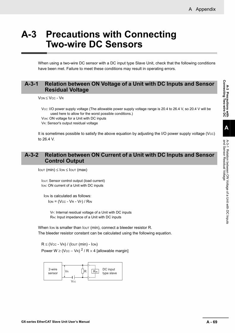
A - 69
A Appendix
GX-series EtherCAT Slave Unit User’s Manual
A-3 Precautions w
ithC
onnecting Two-w
ire DC
A
A-3-1 R
elation between O
N Voltage of a U
nit with D
C Inputs
and Sensor Residual Voltage
A-3 Precautions with Connecting Two-wire DC Sensors
When using a two-wire DC sensor with a DC input type Slave Unit, check that the following conditions have been met. Failure to meet these conditions may result in operating errors.
VON ≤ VCC - VR
VCC: I/O power supply voltage (The allowable power supply voltage range is 20.4 to 26.4 V, so 20.4 V will be used here to allow for the worst possible conditions.)
VON: ON voltage for a Unit with DC inputsVR: Sensor's output residual voltage
It is sometimes possible to satisfy the above equation by adjusting the I/O power supply voltage (VCC) to 26.4 V.
IOUT (min) ≤ ION ≤ IOUT (max)
IOUT: Sensor control output (load current)ION: ON current of a Unit with DC inputs
ION is calculated as follows: ION = (VCC - VR - VF) / RIN
VF: Internal residual voltage of a Unit with DC inputs RIN: Input impedance of a Unit with DC inputs
When ION is smaller than IOUT (min), connect a bleeder resistor R. The bleeder resistor constant can be calculated using the following equation.
R ≤ (VCC - VR) / (IOUT (min) - ION)
Power W ≥ (VCC − VR) 2 / R × 4 [allowable margin]
A-3-1 Relation between ON Voltage of a Unit with DC Inputs and Sensor Residual Voltage
A-3-2 Relation between ON Current of a Unit with DC Inputs and Sensor Control Output
2-wiresensor
DC inputtype slaveRINVR R
VCC
A Appendix
A - 70 GX-series EtherCAT Slave Unit User’s Manual
IOFF ≥ Ileak
IOFF: OFF current of a Unit with DC inputs Ileak: Sensor's leakage current
Connect a bleeder resistor if the sensor's leakage current is greater than the OFF current of a Unit with DC inputs.The bleeder resistor constant can be calculated using the following equation.
R ≤ (IOFF × RIN + VF) / (Ileak - IOFF)
Power W ≥ (VCC − VR) 2 / R × 4 [allowable margin]
A-3-3 Relation between OFF Current of a Unit with DC Inputs and Sensor Leakage Current
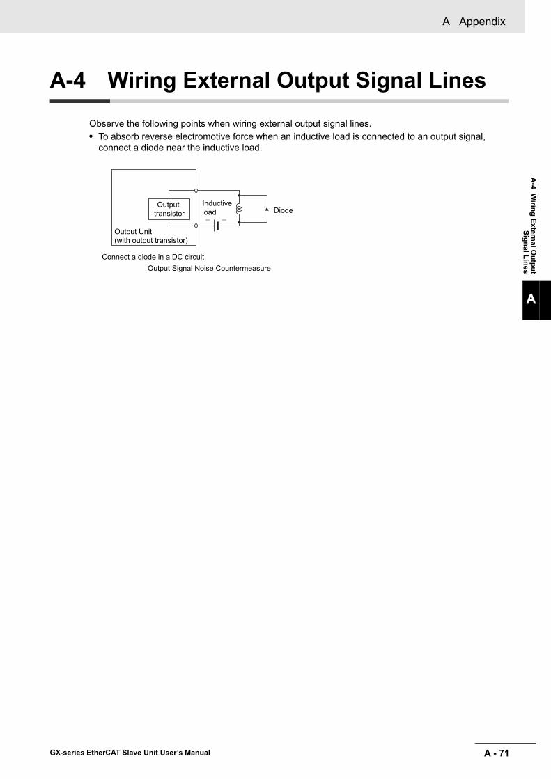
A - 71
A Appendix
GX-series EtherCAT Slave Unit User’s Manual
A-4 W
iring External Output
Signal Lines
A
A-4 Wiring External Output Signal Lines
Observe the following points when wiring external output signal lines.• To absorb reverse electromotive force when an inductive load is connected to an output signal,
connect a diode near the inductive load.
Connect a diode in a DC circuit.Output Signal Noise Countermeasure
Output transistor
Output Unit (with output transistor)
DiodeInductive load
A Appendix
A - 72 GX-series EtherCAT Slave Unit User’s Manual
A-5 I/O Power Supply Current
The I/O power supply current to be supplied to the V and G terminals of each Digital I/O Slave Unit is provided by the following equation.
The points to which I/O power must be supplied are divided into small blocks. The I/O power supply currents supplied to these points are calculated in block units.For example, in a GX-ID1612 Unit, the points are divided into two blocks. One includes 8 points on the left: Inputs 0 to 7. The other contains 8 points on the right: Inputs 8 to 15. Currents are calculated for each block.
Input Slave UnitI/O power supply current supplied to V and G terminals =(Current consumption of Input Slave Unit
from I/O power supply) + (Input current of Input Slave Unit × Number of inputs used) + (Total current consumption of connected input devices)*
* This value does not apply when two-wire input devices are connected.Use the following formula when two-wire input devices are connected:I/O power supply current supplied to V and G terminals = (Current consumption of Input Slave Unit from I/O
power supply) + (Input current of Input Slave Unit × Number of inputs used)
Example:The following example is for when seven, three-wire sensors with a current consumption of 30 mA each are connected to the GX-ID1612.The GX-ID1612 specifications are,
• Input current of 6.0 mA max./point (at 24 VDC)• I/O power supply current consumption of 10 mA max. (at 20.4 to 26.4 VDC).
Therefore,I/O power supply current supplied to V and G terminals =10 mA + (6 mA × 7 points) + (30 mA × 7
points) = 262 mA
Output Slave UnitI/O power supply current supplied to V and G terminals =(Current consumption of Output Slave Unit
from I/O power supply) + (Total load current of the connected loads) + (Total current consumption of connected output devices)*1
*1 This value does not apply when two-wire output devices are connected.Use the following formula when two-wire output devices are connected:I/O power supply current supplied to V and G terminals = (Current consumption of Output Slave Unit from
I/O power supply) + (Total load current of the connected loads)
*2 Compare the value from the above formula to the rated current (common) of the Output Slave Unit and use the smaller value.
Example:The following example is for when five relays with a load current of 20 mA each are connected to the GX-OD1612.The GX-OD1612 specifications are,

A - 73
A Appendix
GX-series EtherCAT Slave Unit User’s Manual
A-5 I/O
Power Supply C
urrent
A
• Rated output current of 4.0 mA/common• I/O power supply current consumption of 10 mA max. (at 20.4 to 26.4 VDC).
Also, relays are two-wire output devices, so there is no output device current consumption.Therefore,I/O power supply current supplied to V and G terminals =10 mA + (20 mA × 5 points) =
110 mA < 4.0 A/common
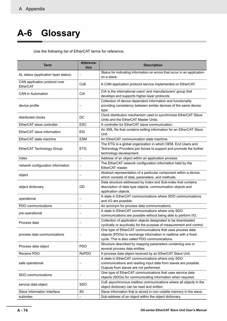
A Appendix
A - 74 GX-series EtherCAT Slave Unit User’s Manual
A-6 Glossary
Use the following list of EtherCAT terms for reference.
Term Abbrevia-tion Description
AL status (application layer status) −Status for indicating information on errors that occur in an application on a slave.
CAN application protocol over EtherCAT
CoE A CAN application protocol service implemented on EtherCAT.
CAN in Automation CiACiA is the international users' and manufacturers' group that develops and supports higher-layer protocols.
device profile −Collection of device dependent information and functionality providing consistency between similar devices of the same device type.
distributed clocks DCClock distribution mechanism used to synchronize EtherCAT Slave Units and the EtherCAT Master Units.
EtherCAT slave controller ESC A controller for EtherCAT slave communication.
EtherCAT slave information ESIAn XML file that contains setting information for an EtherCAT Slave Unit.
EtherCAT state machine ESM An EtherCAT communication state machine.
EtherCAT Technology Group ETGThe ETG is a global organization in which OEM, End Users and Technology Providers join forces to support and promote the further technology development.
index − Address of an object within an application process.
network configuration information −The EtherCAT network configuration information held by the EtherCAT master.
object −Abstract representation of a particular component within a device, which consists of data, parameters, and methods.
object dictionary ODData structure addressed by Index and Sub-index that contains description of data type objects, communication objects and application objects.
operational −A state in EtherCAT communications where SDO communications and I/O are possible.
PDO communications − An acronym for process data communications.
pre-operational −A state in EtherCAT communications where only SDO communications are possible without being able to perform I/O.
Process data −Collection of application objects designated to be downloaded cyclically or acyclically for the purpose of measurement and control.
process data communications −One type of EtherCAT communications that uses process data objects (PDOs) to exchange information in realtime with a fixed cycle. This is also called PDO communications.
Process data object PDOStructure described by mapping parameters containing one or several process data entities.
Receive PDO RxPDO A process data object received by an EtherCAT Slave Unit.
safe operational −A state in EtherCAT communications where only SDO communications and reading input data from slaves are possible. Outputs from slaves are not performed.
SDO communications −One type of EtherCAT communications that uses service data objects (SDOs) for communicating information when required.
service data object SDOCoE asynchronous mailbox communications where all objects in the object dictionary can be read and written.
Slave Information Interface SII Slave information that is stored in non-volatile memory in the slave.subindex − Sub-address of an object within the object dictionary.

A - 75
A Appendix
GX-series EtherCAT Slave Unit User’s Manual
A-6 G
lossary
A
sync manager SMCollection of control elements to coordinate access to concurrently used objects.
Transmit PDO TxPDO A process data object sent from an EtherCAT Slave Unit.
Term Abbrevia-tion Description

A Appendix
A - 76 GX-series EtherCAT Slave Unit User’s Manual

1GX-series EtherCAT Slave Unit User’s Manual
INDEX
A
Abort codes ...................................................................5-10Analog I/O slave ..............................................................2-2Application object ............................................................5-5
C
C/E indicator ...............................................................10-13C/Q indicator ...............................................................10-13CAN application protocol ................................................5-2Clear external latch A generation flag .............................9-7Clear external latch B generation flag .............................9-7Clear present value external reset generation flag .........9-7CN IN connector .............................................................4-7Code + pulse input ........................................................9-10CoE .................................................................................5-2Communications cable ................1-7, 3-4, 4-4, 4-6, 4-7, 6-8Communications error ...................................................8-16Communications Unit ......................................................1-7Configuration Tool ............................................ 1-7, 3-6, 6-6Correctable range ............................................... 8-11, 8-17Count possible/not possible ............................................9-7Counter operation state ..................................................9-6Counter present value .....................................................9-3Counter preset bit .........................................................9-13Counter reset bit ...........................................................9-12Counter status .................................................................9-3Crimp terminal ...............................................................4-13
D
Daisy chain connection ...................................................4-7Diagnosis history ...........................................................5-14Digital I/O slave ...............................................................2-2DIN track .........................................................................4-2DIN track mounting hook ................................................4-2Disconnected line detection .................................... 8-4, 8-5Disconnected line detection flag ...................................8-10
E
e-CON connectors ........................................................4-14Encoder Input Slave Unit ................................................2-2End plate .........................................................................4-2ERR indicator ..............................................................10-12ERR LED ........................................................................6-5ESI file ..................................................................... 1-7, 3-5ESM ................................................................................5-4EtherCAT cables for GX-type ......................................10-19EtherCAT Master ............................................................1-7EtherCAT Master Unit .....................................................3-4EtherCAT slave ...............................................................1-7EtherCAT telegram .........................................................1-3
Expansion Unit ................................................................2-2extension cables from sensors with M12 plugs ..........10-21External control input ...........................................9-12, 9-13External latch A enabled .................................................9-7External latch A generation flag ......................................9-6External latch B enabled .................................................9-7External latch B generation flag ......................................9-6External latch value A .....................................................9-3External reset generation flag .........................................9-6
F
Fixed PDO mapping .......................................................5-7
I
I/O cables for GX-type IO-Link Master Units ...............10-20I/O power supply ..................................... 1-7, 3-4, 4-8, 4-11I/O power supply connector ..........................................4-11I/O power supply terminal .............................................4-11Incremental/decremental pulse input ............................9-10Initialization .....................................................................5-4Input range ......................................................................8-3Input range switch ..................................................8-5, 8-21IO PWR indicator ........................................................10-12IO-Link Master Unit
communications cables ...........................................6-10communications connectors ......................................6-9communications performance ...............................10-16connecting the I/O power supply .............................4-12connecting the Unit power supply ...........................4-10current consumption ............................................... A-68function ....................................................................10-5I/O Data allocations
PDO mapping .................................................10-3IO-Link communications cycle ..............................10-18manufacturer-specific area ..................................... A-51model ........................................................................2-7mounting dimensions ............................................10-15node address setting switches ..................................6-7object dictionary (PDO mapping object) ................. A-21outline ......................................................................10-2part names and functions ......................................10-11specifications ...........................................................10-7unit power supply connector ...................................6-12
L
L/A IN indicator ...........................................................10-12L/A IN Indicator ...............................................................6-4L/A OUT indicator .......................................................10-12L/A OUT Indicator ...........................................................6-4
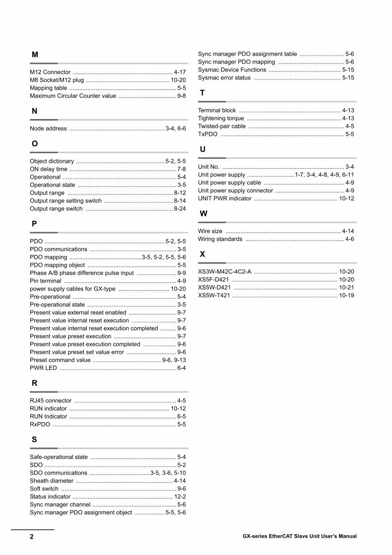
2 GX-series EtherCAT Slave Unit User’s Manual
M
M12 Connector ............................................................. 4-17M8 Socket/M12 plug ................................................... 10-20Mapping table ................................................................. 5-5Maximum Circular Counter value ................................... 9-8
N
Node address .......................................................... 3-4, 6-6
O
Object dictionary ...................................................... 5-2, 5-5ON delay time ................................................................. 7-8Operational ..................................................................... 5-4Operational state ............................................................ 3-5Output range ................................................................ 8-12Output range setting switch .......................................... 8-14Output range switch ..................................................... 8-24
P
PDO ......................................................................... 5-2, 5-5PDO communications ..................................................... 3-5PDO mapping ............................................3-5, 5-2, 5-5, 5-6PDO mapping object ...................................................... 5-5Phase A/B phase difference pulse input ........................ 9-9Pin terminal .................................................................... 4-9power supply cables for GX-type ............................... 10-20Pre-operational ............................................................... 5-4Pre-operational state ...................................................... 3-5Present value external reset enabled ............................. 9-7Present value internal reset execution ........................... 9-7Present value internal reset execution completed .......... 9-6Present value preset execution ...................................... 9-7Present value preset execution completed .................... 9-6Present value preset set value error .............................. 9-6Preset command value .......................................... 9-6, 9-13PWR LED ....................................................................... 6-4
R
RJ45 connector .............................................................. 4-5RUN indicator ............................................................. 10-12RUN Indicator ................................................................. 6-5RxPDO ........................................................................... 5-5
S
Safe-operational state .................................................... 5-4SDO ................................................................................ 5-2SDO communications .....................................3-5, 3-6, 5-10Sheath diameter ........................................................... 4-14Soft switch ...................................................................... 9-6Status indicator ............................................................. 12-2Sync manager channel ................................................... 5-6Sync manager PDO assignment object .................. 5-5, 5-6
Sync manager PDO assignment table ........................... 5-6Sync manager PDO mapping ........................................ 5-6Sysmac Device Functions ............................................ 5-15Sysmac error status ..................................................... 5-15
T
Terminal block .............................................................. 4-13Tightening torque ......................................................... 4-13Twisted-pair cable .......................................................... 4-5TxPDO ........................................................................... 5-5
U
Unit No. .......................................................................... 3-4Unit power supply .............................1-7, 3-4, 4-8, 4-9, 6-11Unit power supply cable ................................................. 4-9Unit power supply connector .......................................... 4-9UNIT PWR indicator ................................................... 10-12
W
Wire size ...................................................................... 4-14Wiring standards ............................................................ 4-6
X
XS3W-M42C-4C2-A ................................................... 10-20XS5F-D421 ................................................................ 10-20XS5W-D421 ............................................................... 10-21XS5W-T421 ................................................................ 10-19

Revision-1GX-series EtherCAT Slave Unit User’s Manual
Revision History
A manual revision code appears as a suffix to the catalog number on the front cover of the manual.
The following table outlines the changes made to the manual during each revision. Page numbers refer to theprevious version.
Revision code Date Revised content01 August 2010 Original production02 September 2010 Added Encoder Input Slave Units GX-EC02xx.03 July 2011 Added functions for change to unit version 1.1 and corrected errors.04 November 2013 Added descriptions and corrected mistakes.05 July 2016 Added GX-ILM08C IO-Link Master Unit.06 October 2016 Corrected mistakes and added information on IO-Link Master Units.
Cat. No. W488-E1-06
Revision code

Revision-2 GX-series EtherCAT Slave Unit User’s Manual


OMRON CANADA, INC. • HEAD OFFICEToronto, ON, Canada • 416.286.6465 • 866.986.6766 • www.omron247.com
OMRON ELECTRONICS DE MEXICO • HEAD OFFICEMéxico DF • 52.55.59.01.43.00 • 01-800-226-6766 • [email protected]
OMRON ELECTRONICS DE MEXICO • SALES OFFICEApodaca, N.L. • 52.81.11.56.99.20 • 01-800-226-6766 • [email protected]
OMRON ELETRÔNICA DO BRASIL LTDA • HEAD OFFICESão Paulo, SP, Brasil • 55.11.2101.6300 • www.omron.com.br
OMRON ARGENTINA • SALES OFFICECono Sur • 54.11.4783.5300
OMRON CHILE • SALES OFFICESantiago • 56.9.9917.3920
OTHER OMRON LATIN AMERICA SALES54.11.4783.5300
Authorized Distributor:
W488-E1-06 10/16 Note: Specifications are subject to change. © 2016 Omron. All Rights Reserved. Printed in U.S.A.
Printed on recycled paper.
OMRON AUTOMATION AMERICAS HEADQUARTERS • Chicago, IL USA • 847.843.7900 • 800.556.6766 • www.omron247.com
OMRON EUROPE B.V. • Wegalaan 67-69, NL-2132 JD, Hoofddorp, The Netherlands. • +31 (0) 23 568 13 00 • www.industrial.omron.eu
Controllers & I/O • Machine Automation Controllers (MAC) • Motion Controllers • Programmable Logic Controllers (PLC) • Temperature Controllers • Remote I/O
Robotics • Industrial Robots • Mobile Robots
Operator Interfaces• Human Machine Interface (HMI)
Motion & Drives• Machine Automation Controllers (MAC) • Motion Controllers • Servo Systems • Frequency Inverters
Vision, Measurement & Identification• Vision Sensors & Systems • Measurement Sensors • Auto Identification Systems
Sensing• Photoelectric Sensors • Fiber-Optic Sensors • Proximity Sensors • Rotary Encoders • Ultrasonic Sensors
Safety • Safety Light Curtains • Safety Laser Scanners • Programmable Safety Systems • Safety Mats and Edges • Safety Door Switches • Emergency Stop Devices • Safety Switches & Operator Controls • Safety Monitoring/Force-guided Relays
Control Components • Power Supplies • Timers • Counters • Programmable Relays • Digital Panel Meters • Monitoring Products
Switches & Relays • Limit Switches • Pushbutton Switches • Electromechanical Relays • Solid State Relays
Software • Programming & Configuration • Runtime