h. mainaud durand on behalf of the clic active pre-alignement team with 3d views and data from...
TRANSCRIPT
H. MAINAUD DURAND
on behalf of the CLIC active pre-alignement team
with 3D views and data from Hubert Gerwig, Richard Rosing and Juha Kemppinen
Pre-alignment status
MDI meeting, 02/09/2011
2
SUMMARY
Monitoring of QD0
Study on cam movers on a 5 DOF setup

3
Monitoring of QD0
Concept
4 Reference Rings (RR) located at each extremity of QD0, supported from outer tube 6 radial spokes per RR
RRRR
RR
RR
spoke
Line of sight for alignment
systems
In two steps:
A monitoring of the position of QD0 w.r.t RR thanks to proximity sensors.(initial calibration of their position performed on a CMM)
A transfer of the position of RR thanks to 6 spokes to alignment systems. By combination of redundant information, the position of the center of 4 RR is computed.

4
Monitoring of QD0
Concept: alignment systems
RasNik
RasCLIC
laser +beam expander
diffractionplate
pixel imagesensor

5
Monitoring of QD0
Latest results: choice of material
RR and spokes in Zerodur

6
Monitoring of QD0
Latest results : design of RR
RR: 6 gage blocks with flat surface, glued between the 2 rings Simulations concerning RR : deformation ~ 1 μm. As we will perform relative measurements, no
impact
7
Monitoring of QD0
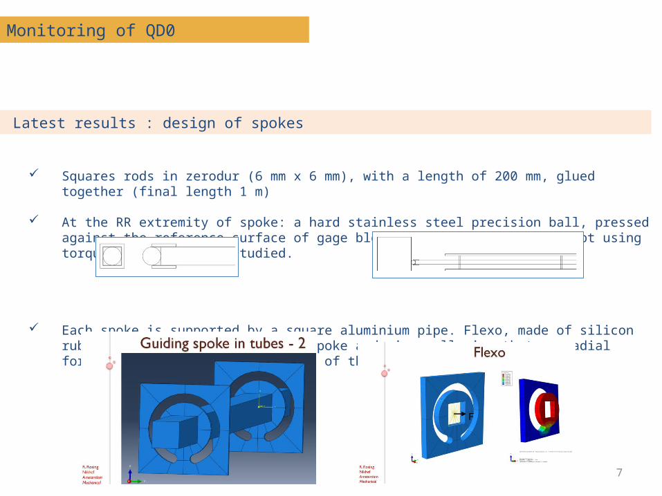
Latest results : design of spokes
Squares rods in zerodur (6 mm x 6 mm), with a length of 200 mm, glued together (final length 1 m)
At the RR extremity of spoke: a hard stainless steel precision ball, pressed against the reference surface of gage block of RR (a screwing concept using torque screw is being studied.
Each spoke is supported by a square aluminium pipe. Flexo, made of silicon rubber will be the link between spoke and pipe, allowing that no radial force is applied, except the load of the bar itself.
8
Monitoring of QD0
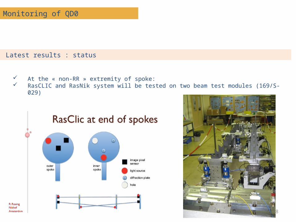
Latest results : status
At the « non-RR » extremity of spoke: RasCLIC and RasNik system will be tested on two beam test modules (169/S-029)

9
Monitoring of QD0
Latest results : status
First tests will concern the assembly of 1m of zerodur rods: guiding, then heating / thermal expansion behavior
10
Monitoring of QD0
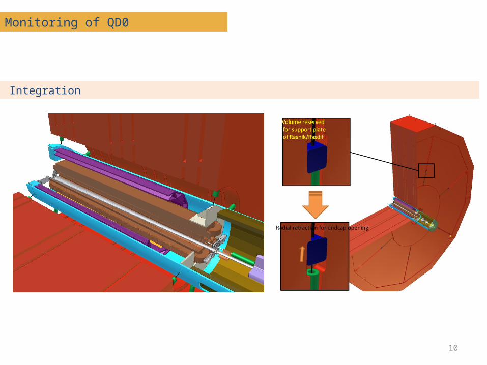
Integration
11
SUMMARY
Monitoring of QD0
Study on cam movers on a 5 DOF setup
12
Monitoring of QD0
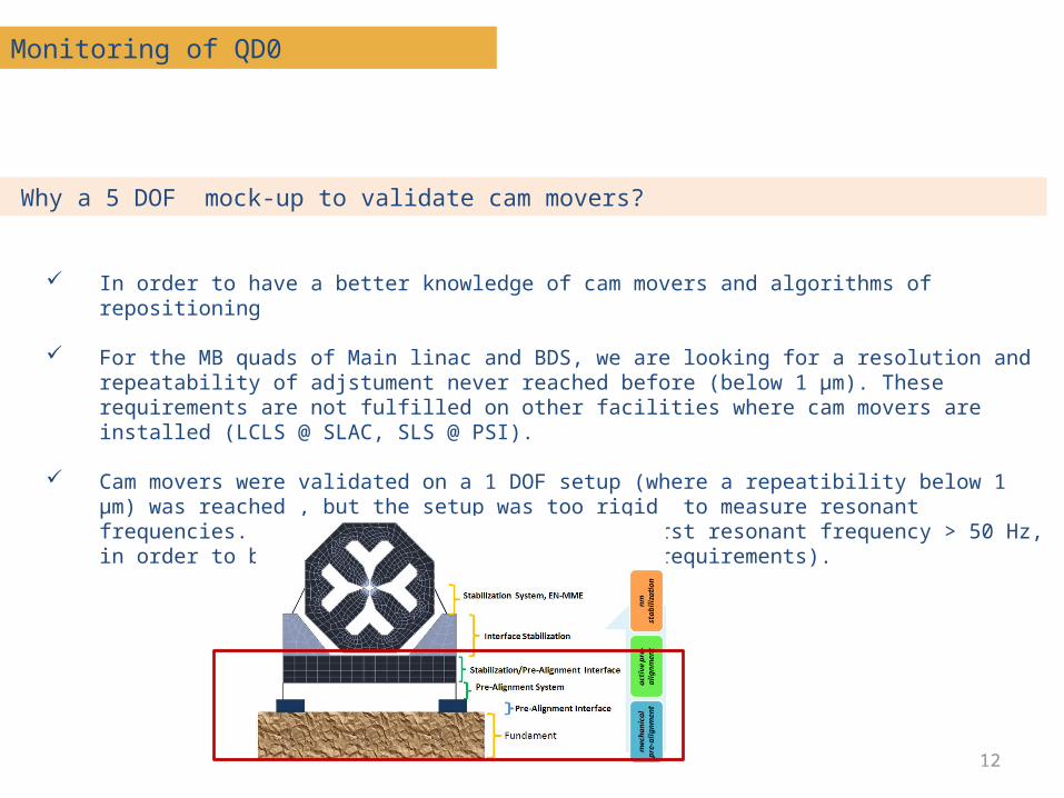
Why a 5 DOF mock-up to validate cam movers?
In order to have a better knowledge of cam movers and algorithms of repositioning
For the MB quads of Main linac and BDS, we are looking for a resolution and repeatability of adjstument never reached before (below 1 μm). These requirements are not fulfilled on other facilities where cam movers are installed (LCLS @ SLAC, SLS @ PSI).
Cam movers were validated on a 1 DOF setup (where a repeatibility below 1 μm) was reached , but the setup was too rigid to measure resonant frequencies. (Target on the 5 DOF mock-up: first resonant frequency > 50 Hz, in order to be compatible with stabilization requirements).

13
Monitoring of QD0
Description of 5 DOF mock-up
14
Monitoring of QD0
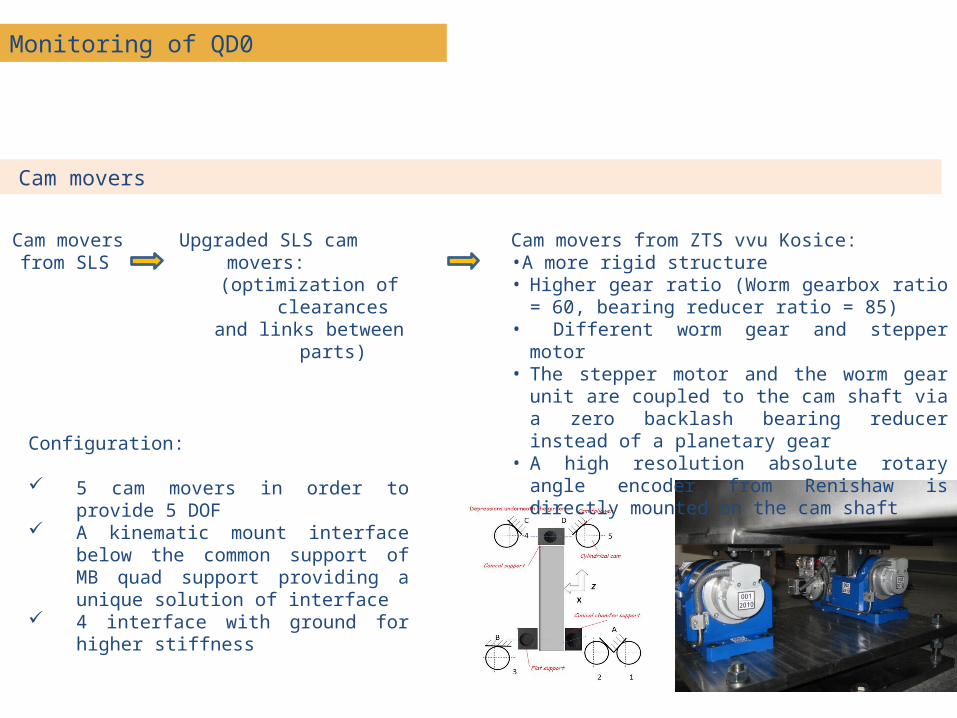
Cam movers
Configuration:
5 cam movers in order to provide 5 DOF
A kinematic mount interface below the common support of MB quad support providing a unique solution of interface
4 interface with ground for higher stiffness
Cam mover
s from SLS
Upgraded SLS cam movers:(optimization of clearancesand links between parts)
Cam movers from ZTS vvu Kosice:•A more rigid structure• Higher gear ratio (Worm gearbox ratio = 60,
bearing reducer ratio = 85) • Different worm gear and stepper motor• The stepper motor and the worm gear unit
are coupled to the cam shaft via a zero backlash bearing reducer instead of a planetary gear
• A high resolution absolute rotary angle encoder from Renishaw is directly mounted on the cam shaft

15
Monitoring of QD0
Latest results
Blank assembly of the setup
Resolution of displacements:
According to the manufacturer, the cam mover’s movement resolution is 3.8’’. Based on this, the 5 DOF setup theoretical resolution in translations is below 1µm and in rotations below 1µrad.
The cam movers were not calibrated before the blank assembly of the 5 DOF setup so the control algorithm cannot be fully exploited. Therefore it was not possible to test the resolution of re-adjustment of all translations and rotations separately.
First tests do however indicate that the re-adjustment resolution of translations are below 2 µm.
But area very noisy: standard deviation of WPS measurements ~ 1.3 μm.
Eigenfrequencies measurements:
Before concrete is added around the plates Several natural frequencies were measured below 50 Hz, coming from the mechanical
plates and their anchoring screws (see edms report n°1152988 from Mechanical Measurement Lab).
A RMS integrated level close to 9 nm at 1 Hz was computed; this confirmed that the area is too noisy for our measurements.

16
Monitoring of QD0
Next steps
Find a new area Calibration of cam movers Remounting of 5 DOF setup, with higher rigidity of mechanical plates Determination of the first resonant frequencies of the support
Extrapolation at MDI case