hardware description language (2) introduction to...
TRANSCRIPT

Hardware Description Language VHDL (1)
Introduction
Abi Farsoni, Department of Nuclear Engineering and Radiation Health Physics, Oregon State University
Digital Radiation Measurement and Spectroscopy
NE/RHP 537

Introduction
• Hardware description language (HDL) – Intended to describe circuits textually, for a computer to read – Evolved starting in the 1970s and 1980s
• Popular languages today include: – VHDL –Defined in 1980s by U.S. military; Ada-like language (Pascal) – Verilog –Defined in 1980s by a company; C-like language – SystemC –Defined in 2000s by several companies; consists of libraries in C++
• VHDL stands for: Very High Speed Integrated Circuit Hardware Description Language
Abi Farsoni, Department of Nuclear Engineering and Radiation Health Physics, Oregon State University

Introduction (Cont.)
• VHDL can describe a digital system at several levels:
– Behavioral • Example: a binary adder, in terms of function of adding two
binary numbers without giving any implementation detail
– Structural • Example: a binary adder, by specifying the interconnections of the
gates that comprise the adder (instantiation of several components)
Abi Farsoni, Department of Nuclear Engineering and Radiation Health Physics, Oregon State University
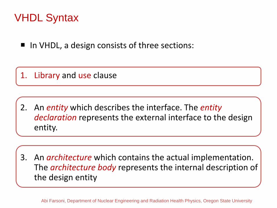
VHDL Syntax
In VHDL, a design consists of three sections:
1. Library and use clause
2. An entity which describes the interface. The entity
declaration represents the external interface to the design entity.
3. An architecture which contains the actual implementation. The architecture body represents the internal description of the design entity
Abi Farsoni, Department of Nuclear Engineering and Radiation Health Physics, Oregon State University

library IEEE; use IEEE.STD_LOGIC_1164.ALL; entity and_gate is Port ( in_1 : in STD_LOGIC; in_2 : in STD_LOGIC; gate_out : out STD_LOGIC); end and_gate; architecture Behavioral of and_gate is Begin gate_out <= in_1 and in_2; end Behavioral;
library clause
VHDL Syntax Example 1: AND gate
Abi Farsoni, Department of Nuclear Engineering and Radiation Health Physics, Oregon State University
Entity
Architecture

• Data types identify a set of values an object may assume and the operations that may be performed on it.
• Type declarations are used through constructs called packages. • We will use the package called std_logic_1164. It contains the
common types, procedures and functions we normally need. • In our class, we will use these two data types: • STD_LOGIC is a data type for a single bit • STD_LOGIC_VECTOR(11 downto 0) is a data type for a12-bit bus
• The std_logic types are defined in std_logic_1164 package.
Abi Farsoni, Department of Nuclear Engineering and Radiation Health Physics, Oregon State University

• The package std_logic_1164 is the package standardized by the IEEE that represents a nine-state logic value system known as MVL9.
• Three of the values, ‘0’ ,‘1’ and ‘Z’, which stand for logical 0, logical 1, and high impedance, can be synthesized.
• Two values, ‘U’ and ‘X’ (“uninitialized” and “unknown”, e.g. when signals with ‘0’ and ‘1’ values are tied together), may be encountered in simulation. The other four values are not used in our application.
• To use the package we say:
LIBRARY ieee; USE ieee.std_logic_1164.ALL;
Abi Farsoni, Department of Nuclear Engineering and Radiation Health Physics, Oregon State University

• Multiplying Operators: *, /, MOD (modulo), REM (reminder)
• Sign operators: +, -
• Adding Operators: +, -, & (concatenation)
• Shift Operators: ROL, ROR, SLA, SLL, SRA, SRL
• Relational Operators: =, /=, <, <=, >, >=
• Logical Operators: AND, OR, NAND, NOR, XOR, XNOR
• Miscellaneous: **, ABS, NOT
Abi Farsoni, Department of Nuclear Engineering and Radiation Health Physics, Oregon State University

• Shift Operators: ROL, ROR, SLA, SLL, SRA, SRL
• Example: Let A = “10010101”
• A SLL 2 = “01010100” --shift left logical, filled with ‘0’
• A SRL 3 = “00010010” --shift right logical, filled with ‘0’
• A SLA 3 = “10101111” --shift left arithmetic, filled with right bit
• A SRA 2 = “11100101” --shift right arithmetic, filled with left bit
• A ROL 3 = “10101100” --rotate left by 3
• A ROR 5 = “10101100” --rotate right by 5
Abi Farsoni, Department of Nuclear Engineering and Radiation Health Physics, Oregon State University

• The symbol “<=“ is the signal assignment operator – Example: C <= A+B; K <= not H ;
• A signal must be assigned after “begin” in the architecture body
• The symbol “=>” is the signal association operator used in instantiation (you will see it later)
Abi Farsoni, Department of Nuclear Engineering and Radiation Health Physics, Oregon State University

• An internal signal must be declared before usage. A signal declaration has a form of:
Signal signal_name : type_name [ := initial_value];
• A signal must be declared before “begin” in the architecture body
• Every line must be terminated with a semicolon “;” • Use “--” for your comments. The text after it is ignored.
– Example: -- this is a comment
Abi Farsoni, Department of Nuclear Engineering and Radiation Health Physics, Oregon State University

entity FullAdder is Port ( a : in STD_LOGIC; b : in STD_LOGIC; cin : in STD_LOGIC; cout : out STD_LOGIC; s : out STD_LOGIC); end FullAdder; architecture Equations of FullAdder is begin s <= (a xor b) xor cin; cout <= (a and b) or (a and cin) or (b and cin); end Equations;
Abi Farsoni, Department of Nuclear Engineering and Radiation Health Physics, Oregon State University

Design Hierarchy
• Provide easier and faster verification and simulation
• Allow several engineers to work on one design at the same time
• Speed up design compilation
• Produce designs that are easier to understand
• Manage the design flow efficiently
Abi Farsoni, Department of Nuclear Engineering and Radiation Health Physics, Oregon State University

Design Hierarchy Example 3: 4-bit Full Adder library IEEE; use IEEE.STD_LOGIC_1164.ALL; entity Adder4 is Port ( x : in STD_LOGIC_VECTOR(3 downto 0); y : in STD_LOGIC_VECTOR(3 downto 0); ci : in STD_LOGIC; co : out STD_LOGIC; s : out STD_LOGIC_VECTOR(3 downto 0)); end Adder4; architecture Structure of Adder4 is component FullAdder --declare FullAdder component port (a : in STD_LOGIC; b : in STD_LOGIC; cin : in STD_LOGIC; cout : out STD_LOGIC; sum : out STD_LOGIC); end component; signal c_int: STD_LOGIC_VECTOR(3 downto 1); --declare internal signal
Abi Farsoni, Department of Nuclear Engineering and Radiation Health Physics, Oregon State University
FA a b
Ci Co
S
FA a b
Ci Co
S FA
a b
Ci Co
S
FA a b
Ci Co
S
X Y
S
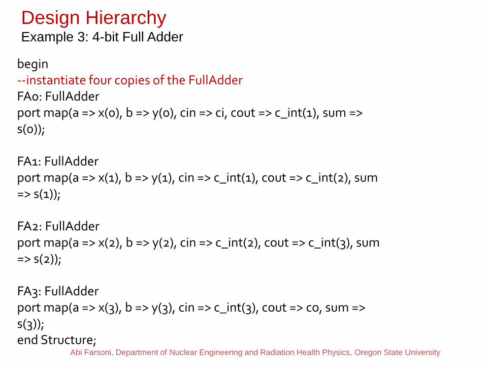
Design Hierarchy Example 3: 4-bit Full Adder begin
--instantiate four copies of the FullAdder FA0: FullAdder port map(a => x(0), b => y(0), cin => ci, cout => c_int(1), sum => s(0)); FA1: FullAdder port map(a => x(1), b => y(1), cin => c_int(1), cout => c_int(2), sum => s(1)); FA2: FullAdder port map(a => x(2), b => y(2), cin => c_int(2), cout => c_int(3), sum => s(2)); FA3: FullAdder port map(a => x(3), b => y(3), cin => c_int(3), cout => co, sum => s(3)); end Structure;
Abi Farsoni, Department of Nuclear Engineering and Radiation Health Physics, Oregon State University
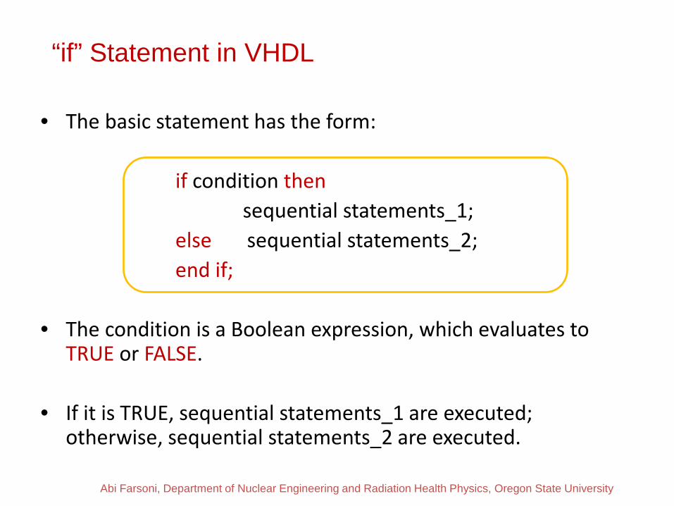
“if” Statement in VHDL
• The basic statement has the form:
if condition then sequential statements_1; else sequential statements_2; end if; • The condition is a Boolean expression, which evaluates to
TRUE or FALSE.
• If it is TRUE, sequential statements_1 are executed; otherwise, sequential statements_2 are executed.
Abi Farsoni, Department of Nuclear Engineering and Radiation Health Physics, Oregon State University

• In a MUX, the control inputs select which one of the data inputs is transmitted to the output
case Sel is when “00” => F <= I0; when “01” => F <= I1; when “10” => F <= I3; when “11” => F <= I4; end case;
Abi Farsoni, Department of Nuclear Engineering and Radiation Health Physics, Oregon State University
I0 I1 I2 I3
F
Sel (1 downto 0)
MUX
4-to-1 Multiplexer

“process” and Modeling Sequential logic
• A process may have the form:
process (sensitivity-list) begin sequential-statements end process; • Whenever one of the signals in the sensitivity list
changes, the sequential statements in the process body are executed.
Abi Farsoni, Department of Nuclear Engineering and Radiation Health Physics, Oregon State University

Modeling a D Flip-Flop Using “Process”
process (clock) begin if clock'event and clock = '1' then if reset = '1' then Q <= '0'; else Q <= D; end if; end if; end process;
Abi Farsoni, Department of Nuclear Engineering and Radiation Health Physics, Oregon State University
D Flip-Flop D Q
Clock
D Flip-Flop with Synchronous Reset
Reset

Modeling a Counter Using “Process”
process_name: -- optional process (clock) begin if clock='1' and clock'event then if reset='1' then count <= (others => '0'); elsif clock_enable='1' then count <= count + 1; end if; end if; end process;
Abi Farsoni, Department of Nuclear Engineering and Radiation Health Physics, Oregon State University
Counter
clock_enable count
clock
Counter with Reset and Clock Enable
reset

1
2
Modeling a State Machine (Moore) in VHDL Using three processes
Abi Farsoni, Department of Nuclear Engineering and Radiation Health Physics, Oregon State University
Define your states
Set initial state and Go to the next state

3
4
Modeling a State Machine (Moore) in VHDL Using three processes
Abi Farsoni, Department of Nuclear Engineering and Radiation Health Physics, Oregon State University
Set outputs based on state only
Set the next state based on some conditions