helena snyman - technical manager and sydney bhengu ... · helena snyman - technical manager and...
TRANSCRIPT

Helena Snyman - Technical Manager and
Sydney Bhengu - Customer Support Technologist
Elster Kent Metering (Pty) Ltd.
South Africa

Electricity meter installation and
installation verification
Safety
NRS 057:2005 (Overview)
Connections
Common Mistakes
Tools to verify meter installations
Quadrants
Vector Diagrams

Safety
Apply appropriate personal protective equipment
(PPE) and follow safe electrical work practices
according to national regulatory practices of
OCCUPATIONAL HEALTH AND SAFETY ACT,
1993 (ACT NO. 85 OF 1993) and NRS 057-
4:2001.
Only qualified electrical workers should install
this equipment.
NEVER work alone.

Safety
NEVER work on a live panel.
Turn off all power supplying the power meter.
Always use a properly rated voltage sensing
device to confirm that all power is off.
Before closing all covers and doors, carefully
inspect the work area for tools and objects that
may have been left inside the equipment.

Safety
Use caution while removing or installing panels
so that they do not extend into the energized
bus; avoid handling the panels, which could
cause personal injury.
The successful operation of this equipment
depends upon proper handling, installation, and
operation.

Safety
NEVER bypass external fusing.
NEVER short the secondary of a PT.
NEVER open circuit a CT; use a shorting block
to short circuit the leads of the CT before
removing the connection from the power meter.
The power meter should be installed in a
suitable electrical enclosure.
Failure to follow this instruction will result in
death or serious injury

NRS 057:2005 Code of practice for electricity metering
4 Requirements of metering installations
4.1 Equipment standards
4.2 Metering system
4.3 General requirements
4.4 Requirements of metering equipment
4.5 Metering installation design
4.6 Metering equipment installation

NRS 057:2005 Code of practice for electricity metering
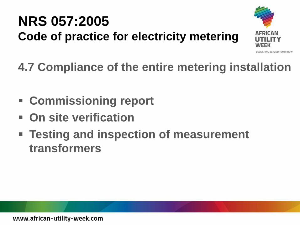
4.7 Compliance of the entire metering
installation
4.8 Automated meter reading (AMR) for large
power users
4.9 Sealing of metering equipment
4.10 Time offset

NRS 057:2005 Code of practice for electricity metering
4.1 Equipment standards
Equipment shall comply with the standards
applicable when originally installed or with an
alternative standard, confirmed in writing by an
accredited test laboratory as being equivalent to,
or better than, the specified standard.

NRS 057:2005 Code of practice for electricity metering
4.2 Metering system
The metering system consists of various
components each of the components has an
influence on the total integrity of the installation.
VT’s, CT’s Junction boxes, Test blocks, Meter
Equipment, Ancillary meter equipment, Data validation
etc.

NRS 057:2005 Code of practice for electricity metering
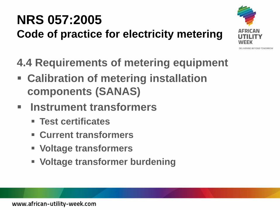
4.4 Requirements of metering equipment
Equipment used in the metering installation shall
be certified as compliant with the relevant
standards and approved by the licensee.
Accuracy class requirements
Consists of a meter(s) and associated instrument
transformers are determined by the nominal size of the
load, expressed in terms of apparent power.
NRS 057:2005 Code of practice for electricity metering
4.4 Requirements of metering equipment
Calibration of metering installation
components (SANAS)
Instrument transformers
Test certificates
Current transformers
Voltage transformers
Voltage transformer burdening

NRS 057:2005 Code of practice for electricity metering
4.4 Requirements of metering equipment
Meter panel ancillary equipment
Test blocks
Meters
General requirements
Meter type testing
Meter calibration
Meter numbering

NRS 057:2005 Code of practice for electricity metering
4.5 Metering installation design
A design report shall be prepared by the
metering designer in the case of a new metering
installation and in the case where an existing
metering installation is modified.

NRS 057:2005 Code of practice for electricity metering
4.6 Metering equipment installation
General (Training)
Meter panel (enclosure)
Instrument transformer earths
Wiring loom
Measurement of current
Measurement of voltage
NRS 057:2005 Code of practice for electricity metering
4.7 Compliance of the entire metering installation
Commissioning report
On site verification
Testing and inspection of measurement
transformers

Connections
Single Phase, Two Wire, Whole Current
Three Phase, Four Wire, Whole Current
Three Phase, Four Wire, CT Connected
Three Phase, Three Wire, CT Connected
Summation

Connections Single Phase, Two Wire, Whole Current
A
N
1 2 3 4
LOA
D
LIN
E

Connections Three Phase, Four Wire, Whole Current
A
B
C
N
A B C N
1 2 3 4 5 6 7 8 9 10 11
S1 VA S2 S1 VB S2 S1 VC S2 Neutral
A
B C
LOA
D
LIN
E
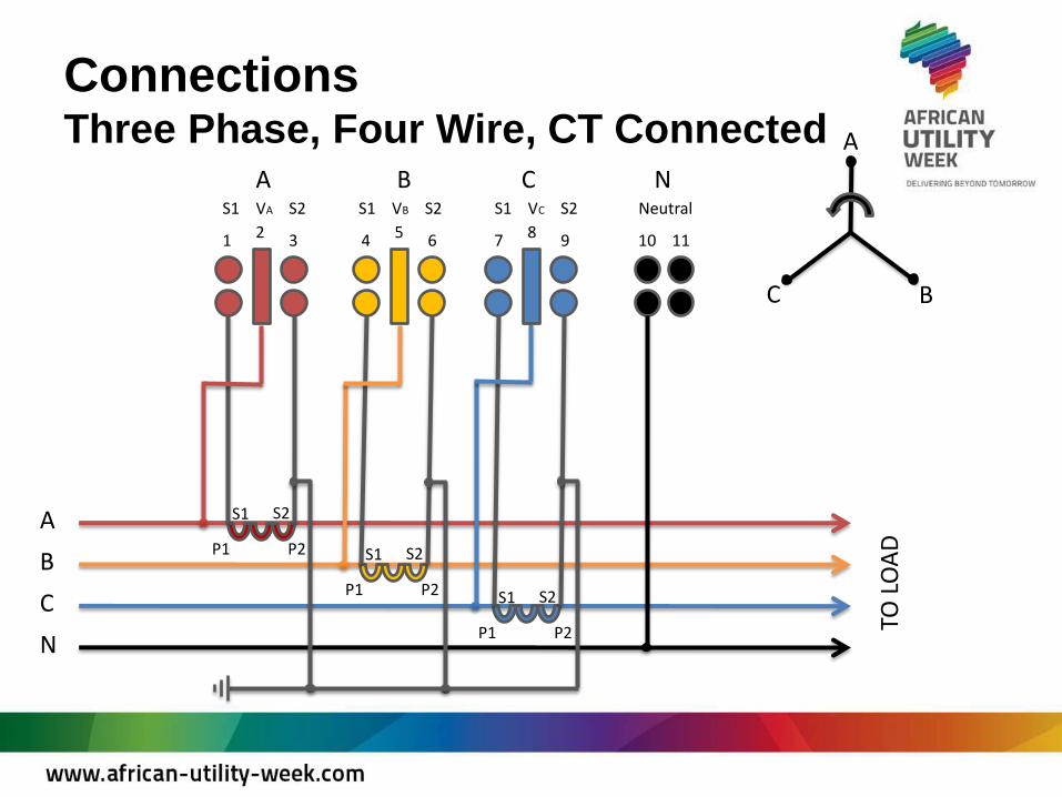
Connections Three Phase, Four Wire, CT Connected
A
B
C
N
A B C N
1 2 3 4 5 6 7 8 9 10 11
S1 VA S2 S1 VB S2 S1 VC S2 Neutral
A
B C
TO L
OA
D
P1 P2
S1 S2
P1 P2
S1 S2
P1 P2
S1 S2

Connections Three Phase, Three Wire, CT Connect
A
B
C
N
A B C N
1 2 3 4 5 6 7 8 9 10 11
S1 VA S2 S1 VB S2 S1 VC S2 Neutral
TO L
OA
D
A
B
C

Connections Summation
A
B
C
N
TO L
OA
D
Fee
de
r 1
A
B
C
TO L
OA
D
Fee
de
r 2
A B C N
1 2 3 4 5 6 7 8 9 10 11
S1 VA S2 S1 VB S2 S1 VC S2 Neutral
S1 S2
S1 S2
S1 S2
S1 S2
S1 S2
S1 S2
S1 S2
P1 P2 P1 P2 P1 P2 P1 P2 P1 P2 P1 P2
S1 S2 S1 S2
Meter
Summation CT’s

Connection
Current Transformer

Common Mistakes
Line and load swapped on whole current meters.
The voltage connections for the respective phases A, B & C
(L1, L2, & L3) must match the voltage designated inputs to
the meter.
The current transformer connections for the respective
phases A,B & C must match the associated voltage phases to
the meter.
The current transformers (CT’s) need to be oriented properly.
Each current transformer indicate the Primary (P1, P2) and
Secondary (S2, S1).
Incorrect CT rations.

Tools to verify the installation
Meter display
Display indications
Instrumentation
Software
Instrumentation (Live Link)
Verification checks
Security data
Load profile events and flags

Tools to verify the installation Display indicators

Tools to verify the installation Display - Instrumentation

Tools to verify the installation Display - Quadrants

Tools to verify the installation Software

Tools to verify the installation Software

Vector Diagrams
3 Phase 4 wire – Unity Power Factor

Vector Diagrams
3 Phase 4 wire – Unity Power Factor

Vector Diagrams
3 Phase 4 wire – 30º Lag

Vector Diagrams
3 Phase 4 wire – 30º Lag

Vector Diagrams
3 Phase 4 wire – Red CT reversed

Vector Diagrams
3 Phase 4 wire – Red CT reversed
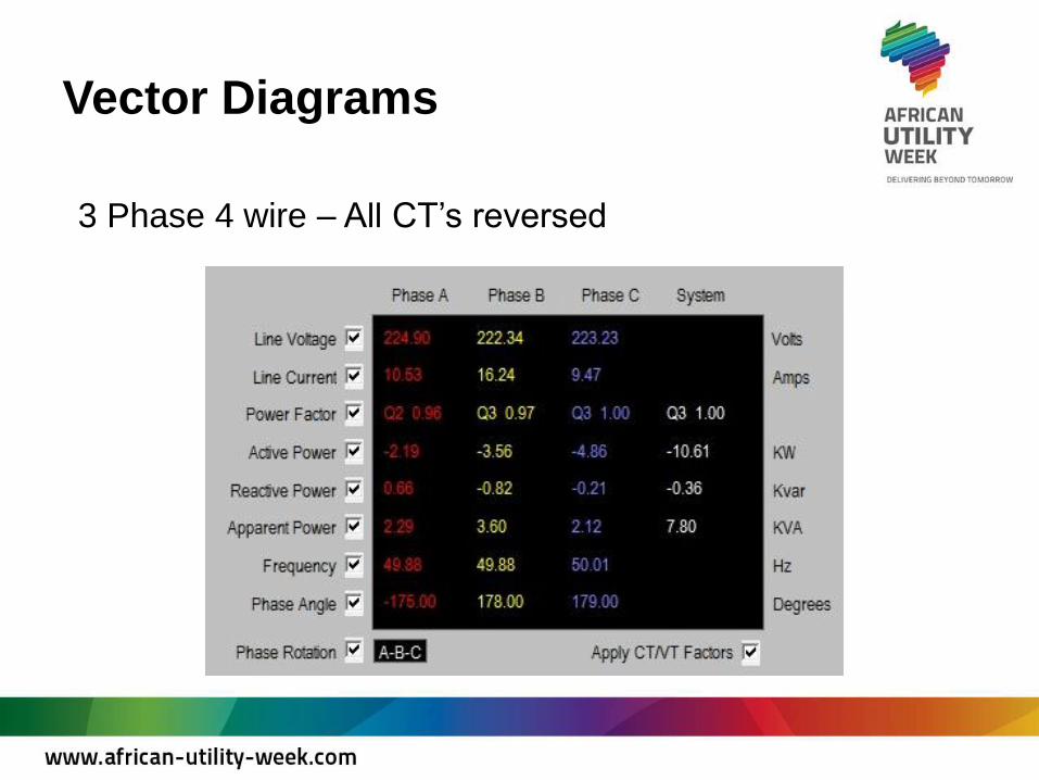
Vector Diagrams
3 Phase 4 wire – All CT’s reversed

Vector Diagrams
3 Phase 4 wire – All CT’s reversed

Vector Diagrams
3 Phase 4 wire – Red an Blue Voltages crossed

Vector Diagrams
3 Phase 4 wire – Red and Blue Voltages crossed

Vector Diagrams
3 Phase 4 wire – All voltages crossed

Vector Diagrams
3 Phase 4 wire – All voltages crossed

Vector Diagrams
3 Phase 4 wire – All Voltages and CT’s crossed

Vector Diagrams
3 Phase 4 wire – All Voltages and CT’s crossed

Vector Diagrams
3 Phase 3 wire – Unity Power Factor

Vector Diagrams
3 Phase 3 wire – Unity Power Factor

Vector Diagrams
3 Phase 3 wire – 30º Lag

Vector Diagrams
3 Phase 3 wire – 30º Lag

Vector Diagrams
3 Phase 3 wire – 30º Lag, Red CT reversed

Vector Diagrams
3 Phase 3 wire – Red and Blue Voltages Crossed

Vector Diagrams
3 Phase 3 wire – 30º Lag, Red and Blue Voltages Crossed