highlander ii sept 23, 2010
TRANSCRIPT

Owner’s Manual FAQ’s
Assembly Instructions Warranty Information
Highlander Wooden Playcenter - 2013
Model: 6010 Manufacturer: Backyard Discovery
3001 North Rouse Pittsburg, KS 66762
Made in China INS-6010-A-Highlander-ENG 1-25-13

Title Page PS Rev. 01/28/2009
Tools Required for Installation: (These are the tools that are generally required for assembly of our playsets. These tools are not included in the playset purchase.)
(Level 24”) (Open end Wrenches (Nut drivers ½” & 7/16” ) ½” & 9/16” )
(Tape Measure) (3/8” Drive Ratchet , ½”& 9/16” std sockets (Claw Hammer) ½” & 9/16 deep sockets)
( 3/8” Cordless Drill or Electric drill) (1/8”, 5/16” & (Drill attachments: 3/8” drill bits) Phillips head screw
3/8” Socket Driver Torque head screw)
(An Adult w/an (Phillips & Straight Blade (Rubber Mallet –Optional) Adult helper) screw drivers)
(Step Ladder)

Owner’s Manual Play Set
Rev12/13/12
Dear Customer: Please read entire booklet completely before beginning the assembly process.
Equipment is recommended for use by children 3 to 10 years of age. Structures are not intended for public use. The Company does not warranty any of its residential structures subjected to commercial use such as: Daycare, Preschool, Nursery School, Recreational Park, or any similar Commercial Application.
WARNING: This Symbol points out important safety instructions which, if not followed, could endanger the personal safety of yourself and your children and/or damage your property. You MUST read and follow all instructions in this manual before attempting to use this playcenter.
WARNING: Children must NOT use this playcenter until unit has been completely assembled and inspected by an adult to insure set has been properly installed and anchored.
Please follow all recommendations below. Failure to do so may result in the warranty being void and/or safety violations that could result in serious injury. This manual contains helpful information concerning Assembly Preparation, Installation Procedure, and Required Maintenance. Always keep the safety of your children in mind as your play structure is being built and as your children play on the set. Before your children play on the set please review the Operation Instructions with them to help ensure their safety.
PLEASE RETAIN THESE INSTRUCTIONS FOR FUTURE REFERENCE. KEEP THEM IN A SAFE PLACE WHERE YOU CAN REFER TO THEM AS NEEDED. IN ORDER TO PROVIDE YOU WITH THE MOST EFFICIENT SERVICE, IT IS REQUIRED THAT YOU PROVIDE US WITH THE PART NUMBERS WHEN ORDERING PARTS.
For Your Records: Please take time and fill out the information below. This information will be needed for warranty issues.
Where Purchased: ____________________ Date of Purchase: ____________________
Installation Date: _____________________ Installed by: _________________________ Tracking Number: ____________________
Tracking Number Reference Label Tracking ID number on the carton and back of the ID plate are included for tracking purposes associated with warranty claims.
Staple Receipt Here
PAGE 1

Owner’s Manual Play Set
Rev12/13/12
Please refer to the Assembly section of the Assembly Manual for Maximum Fall Height.
Positioning Your Playcenter
1. The Playcenter is designed to be installed on a level surface by an Adult with an Adulthelper. Place in a flat area of your yard to minimize ground preparation.
2. Choose a level location for the equipment. This can reduce the likelihood of the play settipping over and loose-fill surfacing material washing away during heavy rains.
3. Place the equipment not less than 6 ft (1.8 m) from any structure or obstruction such as afence, garage, house, overhanging branches, laundry lines, or electrical wires.
4. Provide enough room so that the children can use the equipment safely. For example, forstructures with multiple play activities, a slide should not exit in front of a swing.
5. It is a good idea to place your Playcenter in an area that is convenient for adults to watchchildren at play.
6. Create a site free of obstacles that could cause injuries – such as low overhanging treebranches, overhead wires, tree stumps and/or roots, large rocks, bricks and concrete.Additional suggestions in the Suggested Playground Surfacing Section.
7. Do not build your playset on top of surfacing material.8. Locate bare metal platforms and slides out of direct sunlight to reduce the likelihood of serious
burns. A slide that faces north will receive the least direct sunlight.9. Separate active and quiet activities from each other. For example, locate sandboxes away
from swings or use a guardrail or barrier to separate the sandbox from the movement of theswings.
Suggested Playground Surfacing
� Do not install home playground equipment over concrete, asphalt, packed earth, grass, carpet,or any other hard surface. A fall onto a hard surface can result in serious injury to theequipment user.
� Do not install loose fill surfacing over hard surfaces such as concrete or asphalt.� Shredded bark mulch, wood chips, fine sand and fine gravel, are added as shock absorbing
materials after assembly. If used properly these materials can absorb some of the impact of achild’s fall.
� All surface material should extend a minimum of 6 feet in all directions around the play area.� Do not apply playground surfacing until after the unit is completely constructed. Playset should
not be built on top of surfacing.� Use containment, such as digging out around the perimeter and/or lining the perimeter with
landscape edging.� Installations of rubber tiles or poured-in-place surfaces (other than loose-fill materials)
generally require a professional and are not “do-it-yourself” projects.� Shall use Playground Surfacing Materials (other than loose-fill material) which comply with the
safety standard ASTM F1292 Standard Specification of Impact Attenuation of SurfacingMaterials within the Use Zone of Playground Equipment.
PAGE 2

Owner’s Manual Play Set
Rev12/13/12
The following chart explains the fall height in feet from which a life threatening head injury would not be expected
Critical Heights in feet (m) of Tested Materials Material Uncompressed Depth Compressed Depth
6" (152mm) 9" (228mm) 12" (304mm) to 9" (228mm)
Wood Chips 7' (2.13m) 10' (3.05m) 11' (3.35m) 10' (3.05m)
Double-Shredded bark mulch 6' (1.83m) 10' (3.05m) 11' (3.35m) 7' (2.13m)
Engineered Wood Fibers 6' (1.83m) 7' (2.13m) >12' (3.66m) 6' (1.83m)
Fine Sand 5' (1.52m) 5' (1.52m) 9' (2.74m) 5' (1.52m)
Coarse Sand 5' (1.52m) 5' (1.52m) 6' (1.83m) 4' (1.22m)
Fine Gravel 5' (1.52m) 7' (2.13m) 10' (3.05m) 6' (1.83m)
Medium Gravel 5' (1.52m) 5' (1.52m) 6' (1.83m) 5' (1.52m)
Shredded Tires* 10-12' (3.0-3.6m) N/A N/A N/A
*This data is from tests conducted by independent testing laboratories on a 6-inch depth of uncompressed shredded tire samples produced by four manufacturers. The testsreported critical heights, which varied from 10 feet to greater than 12 feet. It is recommended that persons seeking to install shredded tires as a protective surface request test
data from the supplier showing the critical height of the material when it was tested in accordance with ASTM F1292.
Operating Instructions:
NOTE: Your children’s safety is our #1 concern. Observing the following statements and warnings reduces the likelihood of serious or fatal injury. Please review these safety rules regularly with your children.
1. This Playcenter is designed for specific number of occupants whose combined weight shouldnot exceed a designated weight on the elevated floor or the swing area, the total Unit capacityis outlined in the Basic Setup Dimensions section of instruction manual. The maximum fallheight and recommended play area is also available in the Basic Setup Dimensions section ofthe manual for the specific unit.
2. On-site adult supervision is required.3. Instruct children not to walk close to, in front of, behind, or between moving swings or other
moving playground equipment.4. Instruct children to sit in and never stand on swings5. Instruct children not to twist the chains and ropes and not to loop them over the top support
bar, since this may reduce the strength of the chain or rope.6. Instruct children not to jump from swings or other playground equipment in motion.7. Instruct children to not to push empty seats. The seat may hit them and cause serious injury.8. Instruct and teach children to sit in the center of the swings with their full weight on the seats.9. Instruct children not to use the equipment in a manner other than intended.10. Instruct children to always go down slides feet first. Never slide head first.11. Instruct children to look before they slide to make sure no one is at the bottom.12. Instruct children to never run up a slide, as this increases their chances of falling.13. The parents should dress children appropriately. (Examples would include the use of well-
fitting shoes and the avoidance of ponchos, scarfs, and other loose-fitting clothing that ispotentially hazardous while using equipment).
14. Instruct children not to climb when the equipment is wet.15. Instruct children to never jump from a fort deck. They should always use the ladder, ramp or
slide.16. Instruct children to never crawl or walk across the top of monkey bars.17. Instruct children to never crawl on top of a fort roof.
PAGE 3

Owner’s Manual Play Set
Rev12/13/12
18. Verify that any suspended climbing ropes, chain, or cable are secured at both ends and thatthey cannot be looped back on it.
19. Instruct children not to attach items to the playground equipment that are not specificallydesigned for use with the equipment, such as, but not limited to, jump ropes, clothesline, petleashes, cables and chain as they may cause a strangulation hazard.
20. Instruct children to never wrap their legs around swing chain.21. Instruct children to never slide down the swing chain.22. Instruct children to remove their bike or other sports helmet before playing on playground
equipment.
Maintenance Instructions:
At the beginning of each play season:
• Tighten all hardware.• Lubricate all metallic moving parts per manufacturer’s instructions.• Check all protective coverings on bolts, pipes, edges, and corners. Replace if they are loose,cracked, or missing. • Check all moving parts including swing seats, ropes, cables, and chains for wear, rust, orother deterioration. Replace as needed. • Check metal parts for rust. If found, sand and repaint using a non Lead-based paint meetingthe requirements of 16 CFR 1303. • Check all wood members for deterioration and splinters. Sand down splinters and replacedeteriorating wood members. • Reinstall any plastic parts, such as swing seats or any other items that were removed for thecold season. • Rake and check depth of loose fill protective surfacing materials to prevent compaction andto maintain appropriate depth. Replace as necessary.
Twice a month during play season:
• Tighten all hardware.• Check all protective coverings on bolts, pipes, edges, and corners. Replace if they are loose,cracked, or missing. • Rake and check depth of loose fill protective surfacing materials to prevent compaction andto maintain appropriate depth. Replace as necessary. • Once a month during play season.• Lubricate all metallic moving parts per manufacturer’s instructions.• Check all moving parts including swing seats, ropes, cables, and chains for wear, rust, orother deterioration. Replace as needed.
At the end of each play season or when the temperature drops below 32° F:
• Remove plastic swing seats and other items as specified by the manufacturer and takeindoors or do not use. • Rake and check depth of loose fill protective surfacing materials to prevent compaction andto maintain appropriate depth. Replace as necessary.
Owners shall be responsible for maintaining the legibility of the warning labels.
PAGE 4

Owner’s Manual Play Set
Rev12/13/12
Additional Maintenance:
• Check the swing beam and hardware every two weeks due to wood expansion andcontraction. It is particularly important that this procedure be followed at the beginning of each season. • Inspect wood parts monthly. The grain of the wood sometimes will lift in the dry seasoncausing splinters to appear. Light sand may be necessary to maintain a safe playing environment. Treat your playset with stain regularly, to help prevent severe checking/splitting and other weather damage.
• A waterbourne transparent stain has been applied to your playset. This is done for color only.Once or twice a year, depending on your climate conditions, you must apply some type of protection (sealant) to the wood of your unit. Prior to the application of sealant, lightly sand any “rough” spots on your playset. Please note this is a requirement of your warranty.
• Assembling and maintaining the playset on a level location is very important. As your childrenplay, your playset will slowly dig its way into the soil, and it is very important that it settles evenly. Make sure the playset is level and true one each year or at the beginning of each play season.
Disposal Instructions:
When the Playcenter use is no longer desired, it should be disassembled and disposed of in such a way that no unreasonable hazards will exist at the time the unit is discarded.
Third Party Assembly:
Customer may, in their sole discretion, elect to use a third party person or service to assemble this product. Backyard Discovery assumes no responsibility or liability for any charge incurred by the Customer for any assembly services’. Please see our warranty for more information about damaged and missing part replacement coverage. Backyard Discovery will not reimburse Customer for the price of parts purchased.
PAGE 5

Owner’s Manual Play Set
Rev12/13/12
APPENDIX A
Information on Playground Surfacing Materials:
The following information is from the United States Consumer Product Safety Commission’s Information Sheet for playground surfacing material; also see the following website for additional information: www.cpsc.gov/cpscpub/pubs/323.html.
X3. SECTION 4 OF THE CONSUMER PRODUCT SAFETY COMMISSION’S OUTDOOR HOME PLAYGROUND SAFETY
HANDBOOK9
X3.1 Select Protective Surfacing—One of the most important things you can do to reduce the likelihood of
serious head injuries is to install shock-absorbing protective surfacing under and around your play equipment. The
protective surfacing should be applied to a depth that is suitable for the equipment height in accordance with ASTM
Specification F 1292. There are different types of surfacing to choose from; whichever product you select, follow these
guidelines:
X3.1.1 Loose-Fill Materials:
X3.1.1.1 Maintain a minimum depth of 9 inches of loose-fill materials such as wood mulch/chips, engineered wood fiber (EWF), or shredded/recycled rubber mulch for equipment up to 8 feet high; and 9 inches of sand or pea
gravel for equipment up to 5 feet high. NOTE: An initial fill level of 12 inches will compress to about a 9-inch depth of
surfacing overtime. The surfacing will also compact, displace, and settle, and should be periodically refilled to maintain at
least a 9-inch depth.
X3.1.2 Use a minimum of 6 inches of protective surfacing for play equipment less than 4 feet in height. If
maintained properly, this should be adequate. (At depths less than 6 inches, the protective material is too easily
displaced or compacted.) NOTE: Do not install home playground equipment over concrete, asphalt, or any other hard
surface. A fall onto a hard surface can result in serious injury to the equipment user. Grass and dirt are not considered
protective surfacing because wear and environmental factors can reduce their shock absorbing effectiveness. Carpeting
and thin mats are generally not adequate protective surfacing. Ground level equipment such as a sandbox, activity wall, playhouse or other equipment that has no elevated play surface – does not need any protective surfacing.
X3.1.3 Use containment, such as digging out around the perimeter and/or lining the perimeter with landscape
edging. Don’t forget to account for water drainage.
X3.1.3.1 Check and maintain the depth of the loose-fill surfacing material. To maintain the right amount of loose-
fill materials, mark the correct level on play equipment support posts. That way you can easily see when to replenish
and/or redistribute the surfacing.
X3.1.3.2 Do not install loose-fill surfacing over hard surfaces such as concrete or asphalt.
X3.1.4 Poured-In-Place Surfaces or Pre-Manufactured Rubber Tiles — You may be interested in using surfacing
other than loose-fill materials – like rubber tiles or poured-in-place surfaces. X3.1.4.1 Installations of these surfaces generally require a professional and are not “do-it-yourself” projects.
X3.1.4.2 Review surface specification before purchasing this type of surfacing. Ask the installer/manufacturer for
a report showing that the product has been tested to the following safety standard: ASTM F 1292 Standard Specification
for Impact Attenuation of Surfacing Materials within the Use Zone of Playground Equipment. This report should show the
specific height for which the surface is intended to protect against serious head injury. This height should be equal to or
greater than the fall height – vertical distance between a designated play surface (elevated surface for standing, sitting, or
climbing) and the protective surfacing below – of your play equipment.
X3.1.4.3 Check the protective surfacing frequently for wear.
X3.1.5 Placement — Proper placement and maintenance of protective surfacing is essential. Be sure to:
X3.1.5.1 Extend surfacing at least 6 feet from the equipment in all directions. X3.1.5.2 For to-fro swings, extend protective surfacing in front of and behind the swing to a distance equal to
twice the height of the top bar from which the swing is suspended.
9 This information has been extracted from the CPSC publications “Playground Surfacing — Technical
Information Guide” and “Handbook for Public Playground Safety.” Copies of these reports can be obtained by sending a
postcard to the: Office of Public Affairs, U.S. Consumer Product Safety Commission, Washington, D.C., 20207 or call the
toll-free hotline: 1-800-638-2772.
PAGE 6

Owner’s Manual Play Set
Rev12/13/12
The American Society for Testing and Materials takes no position respecting the validity of any parent right
asserted in connection with any item mentioned in this standard. Users of this standard are expressly advised that
determination of the validity of any such parent rights, and the risk of infringement of such rights, are entirely their own
responsibility.
The standard is subject to revision at any time by the responsible technical committee and must be reviewed
every five years and if not revised, either approved or withdrawn. Your comments are invited either for revision of this standard or for additional standards and should be addressed to ASTM Headquarters. Your comments will receive
careful consideration at a meeting of the responsible technical committee, which you may attend. If you feel that your
comments have not received a fair hearing you should make your views known to the ASTM Committee on Standards.
100 Barr Harbor Drive, West Conshohocken, PA 19428.
PAGE 7

Play Set Assembly Manual FAQs:
1. Does the area for the playset need to be level? Yes. Backyard Discovery recommends the playset be
positioned on a flat level area for maximum safety and durability. The stakes provided should be
used to secure it firmly to the ground.
2. What size area is recommended for the playset? Backyard Discovery recommends at least a 6’ (six
foot) perimeter around and above the playset for maximum safety.
3. What age range is appropriate for the playsets? Backyard Discovery playsets are recommended for
children ages 3 – 10 years.
4. Is the wood treated with chemicals? Backyard Discovery uses 100% Chinese Cedar wood which is
naturally bug resistant, decay and rot resistant. To help ensure your child’s safety, our wood is
completely chemical free and we do not use pressure-treated wood. The stain we use is a top coat
using a water-based product that is for appearance only.
5. How often should the playset be stained? Backyard Discovery recommends the playset be stained
once each year. A water or oil based stain can be used at the customer’s discretion.
6. Why does it seem that my swing set is developing cracks? Wood is a natural material; no two
pieces are exactly alike. Each piece has its own characteristics and personality and reacts
differently to climate changes. When any wood product is exposed to the elements, it develops
“wood checks”. A check is the radial separation of the wood fibers running with the grain of the
wood. These are caused by the varying temperature and moisture conditions. A check is not a
crack – it does not affect the strength or durability of the wood or structural integrity of the play
set.
7. Do Backyard Discovery playsets come with a warranty? Yes. All Backyard Discovery products carry a
1-year replacement warranty on all parts for manufacturer’s defect. Our wood carries a 5 year
warranty on rot and decay as well. Please see warranty details for more information.
8. What is the best way to get started assembling the playset? Backyard Discovery recommends
taking all the parts out of the boxes and arranging them by part number before you begin any
assembly. This will not only allow faster assembly, but will also identify any parts that may be
missing or damaged so they can be replaced before assembly. If parts are missing or need
replacement, go to www.swingsetsonline.com/support.aspx and follow the prompts to order them.
Next, read the assembly manual and get the tools ready for the job as recommended in the
manual. If the assembly manual is lost or misplaced a new one can be printed from Backyard
Discovery’s website: www.swingsetsonline.com .
9. The playset seems to rock or sway too much. What’s wrong? Rocking is caused by uneven ground
or obstructions such as rocks, roots, etc. under the ground rails. These should be removed and the
ground underneath re-leveled to prevent rocking. Also ensure the playset is securely staked to the
ground using the stakes provided.
10. The 2”x 4” boards do not measure 2”x 4”. Why not? In the U.S. it’s common practice to describe
lumber dimensions using the rough cut sizes from the sawmill and not the finished dimensions.
Retailers, home stores, etc. all use this accepted practice for describing lumber dimensions.
PAGE 8

However, Backyard Discovery playsets are designed and constructed using the actual dimensions so
everything fits properly and remains so during the life of the playset.
11. The end beam is not straight up and down. Why not? This is normal. Backyard Discovery designs
playsets this way to ensure the strongest structure possible. The slight angle adds strength and
reduces rocking and twisting.
12. The S-hooks for the swings won’t close. What is wrong? Backyard Discovery recommends placing
them on a hard surface such as concrete (don’t do this on anything that will dent such as metal or
finished wood or glass which will break!). It will take quite a few strokes, but the hooks will close.
For more information and frequently asked questions, please refer to our website at
www.swingsetsonline.com .
PAGE 9

Failure to replacethis bolt with a
shorter one couldresult in personal
injury.
LEISURE TIME PRODUCTS, INC GYM SETS USE A FEW STANDARD CONNECTIONS.BECOMING FAMILIAR WITH THESE CONNECTIONS WILL SIMPLIFY ASSEMBLY
AND INSURE A SAFER PLAY PRODUCT FOR YOUR CHILDREN.
USING THE HARDWARE
Check the positioning of parts in each Step's illustration, noting which of the parts should receive the Lock Washer and Barrel Nut. Place the Barrel Nut and Lock Washer in the hole. Align the holes in the parts to be fastened. Start preliminary tightening of bolt into Barrel Nut by hand.
To securely tighten, turn the bolt with an Allen Wrench until the Lock Washer is fully compressed between the head of the bolt and the Barrel Nut.
Note that in some steps the instructions say to tighten "just snug." This means to tighten the bolt just enough to keep the parts together, but loose enough to allow the parts to move. This is necessary to allow squaring and leveling. The bolt will be tightened securely in a following step. All bolts and screws must be tightened securely before the playset is ready for use.
Bolt has been screwed securely into Barrel Nut and Lock Washer and the connection is tight.
Check connections periodically for tightness during the life of the Gym set.
Lock Washer
WHABolt Flat
Washer
Barrel NutHow to use Safe-T-Fuse Fasteners Correct
Assembly
Do notover tighten.
Lock Washer
SAFE- -FUSEIncludes Fastener System
Typical Installation -Lag Screw:Typical Installation -Wood Screw:• Use an electric drill or screw gun to drive screws.• These screws are self-tapping, so no pilotholes are required.• Lubricate the threads of the screwswith beeswax or soap to ease installation and minimize breaking screws.
• It is very important to make certainthat the tops of all screws are flush with the surface of the wood and there are no protruding sharp edges.
• Always drill pilot holeswhen using LagScrews. The size ofthe pilot hole will bespecified in the Step.
• Tap the head of the LagScrew with a hammer tostart the threads into thewood and then use anwrench to tighten.
Lag Screw
LockWasher
• DO NOT over tighten• DO NOT over tighten
• DO NOT DRIVETOO DEEPAND CAUSE
SPLINTERING
• DO NOT DRIVETOO DEEPAND CAUSE
SPLINTERING
Patent Pending PAGE 10
Spike T-Nut
Check the positioning of parts in each Step's illustration, noting which of the parts should receive the Spike T-Nut. Place the Spike T-Nut in the hole and then seat it with one or two taps of a hammer. Align the holes in the parts to be fastened. Start preliminary tightening of bolt into seated nut by hand.
Bolt has been screwed securely into Spike T-Nut and the connection is tight.
Check connections periodically for tightness during the life of the Gym set.
Correct Assembly
Do notover tighten.
Incorrect AssemblyDuring assembly or maintenance, do not over tighten the bolts. Over tightening can cause the bolt to protrude past the spiked tee nut, which could cause personal injury. Over tightening can also cause the wood to be compressed or to “sink in” the bolt, washer or spiked tee nut. If this has happened, you may need to add additional washers or replace the bolt with a shorter one, so that the bolt does not protrude.

HighlanderHighlanderModel#6010
Assembly RequiresTwo Moderately Skilled People.
For Residential Use Only
If you need assistance with parts or have assembly questions, please call Customer Service
at 800-765-4138Please read the entire instruction manual carefully before proceeding with the assembly or use of
your new gym set. SAVE THIS MANUAL for future reference in the event that you need to contact us for assistance or replacement part information and ordering.
LEISURE TIME PRODUCTS INCPAGE 11

PAGE 12 - SAFE PLAY AREA
Dimensions:
• The Highlander has One layout option.
Layout: Ground Dimension Safe Play Area*14’-8 ½” x 15’-10 ½’’ x 12’-10” high 26’-8 ½” x 33’-6 ½” x 18’-10” high
*Level Ground Surface - See below
• Additional accessories may increase the size of the Safe Play Area.
• Max fall height 91 ½"
General Information:Your set has been designed and engineered for children
only and for residential use only.A maximum of 150 lbs. per child is recommended for
play activities designed for individual use.A maximum of 120 lbs. per child is recommended for
play activities designed for multiple child use.A maximum of 9 children is recommended for this unit.
set.
Back
RightLeft
Front
14'-8 1/2"
15'-10 1/2"
26'-8 1/2"
33'-6 1/2"
96
114 3/4
28 7/16
28 1/2
67 7/8
61 7/8
14
89 1/4
24
18 1/4
27 3/4

LEFTRIGHT
FRONT
PAGE 13 - PARTS LOCATOR
N8
N9
N3
M9
O3
B6
H10
H9
K1
G8
G3
B1
G2
A1
SP1
E2
E1
G1
E3R
E3L
L3
L1
L2
SC2
E6M2
H16
O1
B6
G3G4
E5L
H18
B1
M10
H4

R1
R2L
N8N9
N3
H8
B5B6
B5B4
K1
N1
H2
H8
LEFT
RIGHT
BACK
H10
A1
SP1
E1
G1
E2
M9
M4
H3
E6
G7E6
M10
G3
M9
M9
G2G6
G2G7
G7
H5
M5
M5
M5
M5
M5
M9
M1
E4RE4L
E5RB3
B3
B1
H19
H12
B2
N7
H13
PAGE 14 - PARTS LOCATOR

PAGE 15 - WOODEN PARTS A1 - E4R

PAGE 16 - WOODEN PARTS E5L - G8

PAGE 17 - WOODEN PARTS H1 - H15

PAGE 18 - WOODEN PARTS H16 - M6

PAGE 19 - WOODEN PARTS M7 - R1
3

PAGE 20 - WOODEN PARTS R2L - T1

1/4"x 3/4"BARREL
HEADNUT
H1000791/4 X 1"
PHILLIPSTRUSSHEADBOLT
H100061
#8 X 1-1/4"WOODSCREW
H100087
#8 X 1-1/2"WOODSCREW
H100086
#8 X 2"WOODSCREW
H100111
DRAWINGS ARE TO SCALE BUT SMALL VARIATIONS ARE NORMAL.
5/16 X 3-3/4"HEX
HEADBOLT
H100051
H1000425/16 X 1 1/4"HEX HEAD
BOLT
0
1
2
3
4
5
6
7
8
9
MEASURE BOLTS FROM BOTTOMOF HEAD TO BOTTOM OF BOLT
5/16 X 2"WH HEAD
BOLT
H100011 H100012
WH HEADBOLT
5/16 X 4"WH
HEADBOLT
H100020
3/8 X 5 3/4"HEX
HEADBOLT
H1001175/16 X 5 3/4"
HEXHEADBOLT
H100056
H100090#8 X 2-1/2"
WOODSCREW
H100073 3/8"
SPIKE TEENUT
H1000745/16"
SPIKE TEENUT
1/4 X 3/4"PHILLIPSTRUSSHEADBOLT
H100063
PAGE 21 - HARDWARE
1/4 X 1"STEPBOLT
H100064 1/8" Allen
Wrench
3/8 X 6 1/2"WH
HEADBOLT
H100024
H1000295/16 X 3"
LAGSCREWWH
MEA
SUR
E BO
LTS FRO
M B
OTTO
MO
F HEA
D TO
BO
TTOM
OF B
OLT
H1000285/16 X 2-3/8"
WH LAGSCREW
5/16 X 2"LAG
SCREWWH
H100027
5/16 X1 1/2"WH LAGSCREW
H100026
H1001165/16 X 2-3/8"HEX HEAD
LAG SCREW
WH HEADBOLT5/16 X 1 3/4"
5/16 X 1 1/2"H100010

NO
TE
: QU
AN
TIT
IES
INC
LU
DE
EX
TR
A H
AR
DW
AR
E
PART. . . . . . . . . . . . . . . . . . . . . . . . . . . . . . . DESCRIPTION. . . . . . . . . . . . . . . . . . . . . . . . . . QTY.A100041 . . . . . . . . . . . . . . . . . . . . . . . . . . . . . . . . . . T-40 Wrench. . . . . . . . . . . . . . . . . . . . . . . . . . . . . . . . . . . 2A100042 . . . . . . . . . . . . . . . . . . . . . . . . . . . . . . . . . T-40 Bit For Drill . . . . . . . . . . . . . . . . . . . . . . . . . . . . . . . . . 2H100031 . . . . . . . . . . . . . . . . . . . . . . . Washer Lock Ext (12mm ID x 19 mm OD) . . . . . . . . . . . . . . . . . . . . . . . 8H100010 . . . . . . . . . . . . . . . . . . . . . . . . . . . . . . WH Bolt (5/16” x 1 1/2”) . . . . . . . . . . . . . . . . . . . . . . . . . . . . . . 3H100093. . . . . . . . . . . . . . . . . . . . . Socket Wrench (1/8" - for 1/4-20 x 1" Step Bolt) . . . . . . . . . . . . . . . . . . . . . 1H100117 . . . . . . . . . . . . . . . . . . . . . . . . . . . Hex Head Bolt (3/8”-16 x 5 3/4") . . . . . . . . . . . . . . . . . . . . . . . . . . 9H100024 . . . . . . . . . . . . . . . . . . . . . . . . . . . . . WH Bolt (3/8”-16 x 6 1/2”) . . . . . . . . . . . . . . . . . . . . . . . . . . . . . 1H100056 . . . . . . . . . . . . . . . . . . . . . . . . . . . Hex Head Bolt (5/16” x 5-3/4”). . . . . . . . . . . . . . . . . . . . . . . . . . . 2H100020 . . . . . . . . . . . . . . . . . . . . . . . . . . . . . . . WH Bolt (5/16" x 4") . . . . . . . . . . . . . . . . . . . . . . . . . . . . . . 62H100012 . . . . . . . . . . . . . . . . . . . . . . . . . . . . . . . WH Bolt (5/16" x 2") . . . . . . . . . . . . . . . . . . . . . . . . . . . . . . 23H100011 . . . . . . . . . . . . . . . . . . . . . . . . . . . . . . WH Bolt (5/16" x 1 3/4") . . . . . . . . . . . . . . . . . . . . . . . . . . . . . 1H100064 . . . . . . . . . . . . Step bolt (1/4-20 x 1" - w/ 7/8" Head Diameter & 1/8" Socket Drive) . . . . . . . . . . . . . 3H100079 . . . . . . . . . . . . . . . . . . . . . . . . Phillips Barrel Nut (1/4-20 x 3/4" long). . . . . . . . . . . . . . . . . . . . . . . . 53H100061 . . . . . . . . . . . . . . . . . . . . . . . . . . . . . . . . PTH Bolt (1/4 x 1”) . . . . . . . . . . . . . . . . . . . . . . . . . . . . . . . 11H100063 . . . . . . . . . . . . . . . . . . . . . . . . . . . . . . . PTH Bolt (1/4 x 3/4”) . . . . . . . . . . . . . . . . . . . . . . . . . . . . . . 37H100022. . . . . . . . . . . . . . . . . . . . . . . . . . . . . . . . WH Bolt (5/16 x 5”) . . . . . . . . . . . . . . . . . . . . . . . . . . . . . . . 4H100005 . . . . . . . . . . . . . . . . . . . . . . . . . . . . WH Nut Barrel (5/16 x 7/8”) . . . . . . . . . . . . . . . . . . . . . . . . . . . . 2H100029 . . . . . . . . . . . . . . . . . . . . . . . . . . . . WH Lag Screw (5/16" x 3") . . . . . . . . . . . . . . . . . . . . . . . . . . . . 2H100028 . . . . . . . . . . . . . . . . . . . . . . . . . . . WH Lag Screw (5/16" x 2 3/8") . . . . . . . . . . . . . . . . . . . . . . . . . . 58H100027 . . . . . . . . . . . . . . . . . . . . . . . . . . . . WH Lag Screw (5/16" x 2") . . . . . . . . . . . . . . . . . . . . . . . . . . . 42H100026 . . . . . . . . . . . . . . . . . . . . . . . . . . . WH Lag Screw (5/16" x 1 1/2") . . . . . . . . . . . . . . . . . . . . . . . . . . 20H100090 . . . . . . . . . . . . . . . . . . . . . . Wood Screw (#8 x 2 1/2" Type 17 w/nibs) . . . . . . . . . . . . . . . . . . . . . . 15H100111 . . . . . . . . . . . . . . . . . . . . . . . . Wood Screw (#8 x 2" Type 17 w/nibs) . . . . . . . . . . . . . . . . . . . . . . . 51H100086 . . . . . . . . . . . . . . . . . . . . . . Wood Screw (#8 x 1 1/2" Type 17 w/nibs) . . . . . . . . . . . . . . . . . . . . . 494H100087 . . . . . . . . . . . . . . . . . . . . . . Wood Screw (#8 x 1 1/4" Type 17 w/nibs) . . . . . . . . . . . . . . . . . . . . . 332H100073 . . . . . . . . . . . . . . . . . . . . . . . . . . . . . T-nut (3/8" X 5/8" Long) . . . . . . . . . . . . . . . . . . . . . . . . . . . . . 10H100104. . . . . . . . . . . . . . . . . . . . . . . . . . Flat Washer (19mm OD x 8mm ID) . . . . . . . . . . . . . . . . . . . . . . . . 19H100107 . . . . . . . . . . . . . . . . . . Internal Tooth Lock Washer (18mm OD x 10mm ID). . . . . . . . . . . . . . . . . . 10H100074. . . . . . . . . . . . . . . . . . . . . . . . . . . . . . . . . . . T-nut (5/16") . . . . . . . . . . . . . . . . . . . . . . . . . . . . . . . . . 90H100110 . . . . . . . . . . . . . . . . . . . . . . . . . . . . . . . . . Lock Nut (5/16") . . . . . . . . . . . . . . . . . . . . . . . . . . . . . . . . 15H100102 . . . . . . . . . . . . . . . . . . . . . . . . . Flat Washer (25mm OD x 11mm ID) . . . . . . . . . . . . . . . . . . . . . . . . 10H100108. . . . . . . . . . . . . . . . . . . . Internal Tooth Lock Washer (15mm OD x 8mm ID) . . . . . . . . . . . . . . . . . . . 72H100105. . . . . . . . . . . . . . . . . . . . . . . . . . . . . Fender Washer (8 x 27mm). . . . . . . . . . . . . . . . . . . . . . . . . . . . 64H100030 . . . . . . . . . . . . . . . . . . . . . . . . . . Lock Washer EXT 8mm x 19mm. . . . . . . . . . . . . . . . . . . . . . . . . 241H100031 . . . . . . . . . . . . . . . . . . . . . . . . . . Lock Washer Ext 12mm x 19mm. . . . . . . . . . . . . . . . . . . . . . . . . . . 6H100042 . . . . . . . . . . . . . . . . . . . . . . . . . . . . . . Bolt Hex (5/16” x 1 1/4”) . . . . . . . . . . . . . . . . . . . . . . . . . . . . . . 4H100106 . . . . . . . . . . . . . . . . . . . . . . . . . Flat Washer (9mm ID x 18 MM OD). . . . . . . . . . . . . . . . . . . . . . . . . . 8H100095 . . . . . . . . . . . . . . . . . . . . . . . . . . . . . . . Split Washer 5/16” . . . . . . . . . . . . . . . . . . . . . . . . . . . . . . . . 6H100051. . . . . . . . . . . . . . . . . . . . . . . . . . . . . . Hex Bolt (5/16” x 3-3/4”) . . . . . . . . . . . . . . . . . . . . . . . . . . . . . . 4H100116 . . . . . . . . . . . . . . . . . . . . . . . . . Hex HeadLag Screw (5/16" x 2 3/8") . . . . . . . . . . . . . . . . . . . . . . . . . 8
(5/16")Lock Nut
H100110
5/16" FlatWasher
H100104
Fender Washer
H10010511 x 25Flat
Washer
H10010210 x 18InternalToothLock
Washer
H100107H100108
8 x 15InternalToothLock
Washer
PAGE 22 - HARDWARE
H100022WHA BOLT (5/16 x 5”)
Not to Scale
H100005WHA NUT BARREL
(5/16 x 7/8”)Not to Scale
Lock WasherH100030
A100042TORX BIT
TORX WRENCHA100041
Lock WasherH100031
5/16" Split WasherH100095
8 x 27
8 x 1912 x 19
9x18" FlatWasher
H100106
H100106 . . . . . . . . . . . . . . . . . . . . . . . . Flat Washer (18mm OD x 9mm ID) . . . . . . . . . . . . . . . . . . . . . . . 10

LARGE METAL TRIANGLE
2 REQUIRED
ADDITIONAL ITEMS
X20-GGREEN
PLASTIC ROCKS12 REQUIRED
2" x2" METAL BRACKET
3 REQUIRED
BAG OF 4• SWING HANGER,
• CARABINER,• PLASTIC TUBE
Y40-HD4
1 - ASSEMBLY MANUAL1 - 50226 - 10 FT. SLIDE
1 - HARDWARE KIT6 - Y41 GROUND STAKES
2" x 1.25 x 3.25"- 1/8” Thick METAL BRACKET
2 REQUIRED
PRODUCTSSILOAM SPRINGS, AR 72761
PHONE 866-362-1123
TH 0IS 1 P OL TA Y 2S E ST E I GS A I N NTE END DRED F CHILOR
METAL ID PLAQUE
Z1QUICK LINK SWING HANGER 4 REQUIRED
X11-CAY2 - GLIDER ARMS
1 -GLIDER SEAT
A100004
Y30-40G
Y1-105G
Y50-LTP
16 1/2"METAL GRIP 8 REQUIRED
Y10-16.5G
X2-GBELT SWING 2 REQUIRED
Y60-62GCHAIN FOR SWING
4 REQUIRED
5147-1TELESCOPE
W/ MOUNTING BRACE NO MAGNIFICATION
ZQLBI2 BAGS OF
4 QUICK LINKS
PAGE 23 - ACCESSORIES
STEERINGWHEEL
Y25-GGLIDER SUPPORTS
2 REQUIRED
X141 BAG OF 4 CAPS
Y28-G41 BAG OF
4 BUSHINGS
5137-1
Y60-
57G
Y60-
57G

B1B2
B3
G2
G3
H11
H11
PAGE 24
STEP 1
B e g i n b y i n s e r t i n g 5 / 1 6 ” S p i k e T- N u t s i n To w e r L e g s(Per Dia.). Then attach G3 Floor Rail to top of B1 Front, B2 Middle and B3 Back Tower Legs using 5/16”x 4” WH Bolts, and . (Note: Position of small pilot holes in G3 Floor Rail between B2 and B3 Tower Legs and towards top).
Attach H11 Floor Rail to B1 and B2 and another H11 Floor Rail to B2 and B3 with 5/16”x 4” WH Bolts, 5/16” and Lock Washers into the 5/16” Spike T-Nuts inserted earlier.
Use Holes in G2 Base Board to Pilot Drill B1, B2 and B3 Tower Legs with 3/16” Drill Bit. Now attach using 5/16”x 2-3/8” WH Lag Screws, and Lock Washers.
Repeat Step to construct opposite tower side.
Lock Washers
G3
H11
H11
G2
B1B2B3
B1B2
B3
ITEMS NEEDED (2) G3 Floor Rail(4) H11 Floor Rail (2) G2 Base Board(2) B1 Front Tower Legs(2) B2 Middle Tower Legs(2) B3 Back Tower Legs
HARDWARE NEEDED(22) H100020 - 5/16 X 4" WH Bolts(12) H100028 - 5/16 X 2 3/8" WH Lag Screws(34) H100030 - Lock Washers(22) Spike T Nut

PAGE 25
STEP 2
Attach G4 Wall Rail to B1 Front Tower Legs using 5/16”x 4” WH Bolts, Lock Washers and 5/16” Spike T-Nuts.
Attach G7 Floor Rail to top of B3 Back Tower Legs with 5/16”x 4” WH Bolts, Lock Washers and 5/16” Spike T-Nuts.
Attach another G7 Floor Rail to Bottom of B3 Back Tower Legs with 5/16” x 2-3/8” Lag Screws, Lock Washers and last G7 Floor Rail to B2 Middle Tower Legs. (Note: Position Between B1 and B2 Tower Legs). Pilot Drill and secure with 5/16” x 2-3/8” Lag Screws and Lock Washers .
Attach G6 Base Board to B1 Front Tower Legs using 5/16” x 2-3/8” Lag Screws and Lock Washers. ( Pilot drill using 3/16” drill bit. )
G4
G7
B1B2
B3
B1
B2
B3
G7
G6
G7
G7
B1 B1
B2
B3
B1 B1
G4
G7
ITEMS NEEDED(1) G4 Wall Rail(3) G7 Floor Rails(1) G6 Base Board
HARDWARE NEEDED(4) H100020 - 5/16 X 4" WH Bolts(12) H100028 - 5/16 X 2 3/8 WH Lag Screws(16) H100030 - Lock Washers(4) 5/16" Spike T Nut

PAGE 26
STEP 3
Attach G5 Wall Rail to B2 Middle Tower Legs between B2 and B1 Tower Legs using 5/16”x 4” WH Bolts, Lock Washers and 5/16” Spike T-Nuts. (Note position of arch).
Attach H4 Floor Rail to B1 Front Tower Legs using 5/16”x 4” WH Bolts, Lock Washers and 5/16” Spike T-Nuts. (Note position of holes toward left front).
G6
G7
G7
B1 B1
B2
B3
G5
G6
G7
G7
B1 B1
B2
B3
G5
H4
ITEMS NEEDED(1) G5 Wall Rail(1) H4 Floor Rail
HARDWARE NEEDED(4) H100020 - 5/16” x 4” WH Bolt(4) 5/16” Spike Tee Nut(4) H100030 - Lock Washer

PAGE 27
STEP 4
Attach H5 Floor Rail to B2 Middle Tower Legs between B2 and B1 Tower Legs. Also note position of holes in H5 so they are on the side of the archway in G5 Rail above. Fasten using 5/16”x 4” WH Bolts, Lock Washers and 5/16” Spike T-Nuts.
Attach H5 Floor Rail to B3 Back Tower Legs so the holes are to the Left Side Back with 5/16”x 4” WH Bolts, Lock Washers and 5/16” Spike T-Nuts.
Attach H6 Floor Rail to B2 Middle Tower Legs between B2 and B1 Tower Legs with 5/16”x 4” WH Bolts, Lock Washersand 5/16” Spike T-Nuts.
B1B2
B3
B1
B2
B3
H5
H5
H4
H6Right Left
B3
B2
B1H4
H5
G5
ITEMS NEEDED(2) H5 Floor Rail(1) H6 Floor Rail
HARDWARE NEEDED(6) H100020 - 5/16” x 4” WH Bolt(6) 5/16” Spike Tee Nut(6) H100030 - Lock Washer

PAGE 28
STEP 5(when using Lag Screws make sure to pilot drill with 3/16” drill bit.)
Making sure structure is level and plumb, attach two (2) E6 Deck Braces Flush to top of H4 Floor Rail with 5/16”x 2-3/8” WH Lag Screws, 5/16” Lock Washers and Fender Washers and to B1 Front Tower Legs with 5/16”x 2-3/8” Hex Head Lag Screw, Lock Washer and 5/16” Flat Washer in counter sunk holes.
Now attach two (2) E6 Deck Braces flush with top of H11 Floor Rails using 5/16”x 2-3/8” WH Lag Screws and s and to B1 Front Tower Legs with 5/16”x 2-3/8” Hex Head Lag Screws, Lock Washer and 5/16” Flat Washer .
Now attach four (4) more E6 Deck Braces to B3 Back Tower Legs and G3 and G7 Floor Rails with 5/16”x 2-3/8” WH Lag Screws, Lock Washers, 5/16” and 5/16” Flat Washers to Tower Legs.
ANCHOR:Position structure at this point making sure that all attachments will be in the proper space for your yard.
Fender Washer
in counter sunk holes
Fender Washers 5/16” x 2-3/8” Hex Head Lag Screws and in counter sunk holes
E6E6
H11 H4
B1
E6 E6E6
E6 G7
B3
B3
G3
G3Position playset in permanent location and secure to ground. Measure in 4" from Tower Legs and 4" from inside of G7 Base board and mark ground. Now measure in 4" from Tower Legs and 4" from outside G6 Base Board and mark ground. This should allow enough space to twist Stakes into ground using screwdriver for leverage.
Twist Stakes until eye is approximately 3" from ground surface.At this point you will need at least two people to slide the set into position next to the Stakes. Using eye in Stake as guide drill thru Base Boards with 3/8" drill bit and attach Stakes with 1" Phillips Truss Head Bolts 5/16" Lock Washers, s and 1/4" Barrel Nuts as shown. Fender Washer
G6
G7
G7
Note: If your ground is loose, sandy or rocky you may need to dig holes and secure Stakes with concrete.
4”4”
Metal Stake
FENDERWASHER
BOLT
LOCKWASHER
BO
AR
D
FENDERWASHER
BARRELNUT
5/16"
Opposite side not shown.
ITEMS NEEDED(8) E6 Deck Braces(4) Y41 Ground Stakes
HARDWARE NEEDED(16) H100028 - 5/16” x 2 3/8” WH Lag Screw(4) ¼” x 1” Phillips Truss Head Bolt(4) ¼” Phillips Barrel Nut(16) H100030 - Lock Washer(8) 5/16” Flat Washer
5/16” FlatWashers
5/16” FlatWashers
5/16” FlatWashers
(8) H100116 5/16” x 2 3/8” - Hex Lag Screws(12) H100108 - 5/16” Lock Washer(8) H100105 - 5/16” Fender Washer

PAGE 29
STEP 6
Attach H7 Floor Joists to H11 Floor Rails using 2-1/2” Wood Screws. Now, attach four (4) SC1 Floor Boards two (2) between B2 and B3 Tower Legs on lower floor and two (2) between B1 and B2 Legs on middle floor using 1-1/2” Wood Screws.
Attach fifteen (15) M3 Floor Boards and one (1) N2 Floor Board to lower floor with 1-1/2” Wood Screws and fifteen (15) M6 Floor Boards and one (1) N4 Floor Board to middle floor with 1-1/2” Wood Screws. (Note: space evenly).
N4
N2
M3
M6
B3
B3
B2
B2
B1B1
SC1
SC1
SC1
SC1
B1
B1
B2
B2
B3 B3
B1B2
B3
B1
B2B3
H5
H7
H5
H7
H6
ITEMS NEEDED(2) H7 Floor Joists(4) SC1 Floor Boards(15) M3 Floor Boards(15) M6 Floor Boards(1) N2 Floor Boards(1) N4 Floor Boards
HARDWARE NEEDED(8) 2 ½” Wood Screws(172) 1 ½” Wood Screws

PAGE 30
STEP 7
Attach B6 Porch Roof Supports to G3 and G4 Floor Rails above B1 Front Tower Legs with 5/16”x 4” WH Bolts, Lock Washers and 5/16” Spike T-Nuts.
Attach two (2) B4 Club House Legs to G3, G7 and G5 Floor Rails above B2 middle Tower Leg and B3 Back Tower Leg on right side of structure with 5/16”x 4” WH Bolts, Lock Washers and 5/16” Spike T-Nuts.
Attach two (2) B5 Club House Legs to G3, G7 and G5 above B2 and B3 tower Legs on left side of structure using 5/16” x 4” WH Bolts, Lock Washers and 5/16” Spike T Nuts.
G4
G3
G3
G7 G5
B6
B6
B4B4 B5
B5
B1B2
B3
B3 B2
B1
ITEMS NEEDED(2) B6 Porch Roof Supports(2) B5 Club House Legs(2) B4 Club House Legs
HARDWARE NEEDED(12) H100020 - 5/16” x 4” WH Bolt(12) 5/16” Spike Tee Nut(12) H100030 - Lock Washer

PAGE 31
STEP 8
Secure H7 Floor Joist to G3 Floor Rails with 2-1/2” Wood Screws.
Now attach SC1 Floor Boards between B4 and B5 Club House Legs. Now attach fifteen (15) M3 Floor Boards and one (1) N2 Floor Board to upper floor with 1-1/2” Wood Screws. (Note: Space evenly)
H7
M3
N2
SC1SC1
B5
B5B4B4
ITEMS NEEDED(1) H7 Floor Joist(2) SC1 Floor Boards(15) M3 Floor Boards(1) N2 Floor Board
HARDWARE NEEDED(4) 2 ½” Wood Screw(86) 1 ½” Wood Screw
G7
PAGE 32
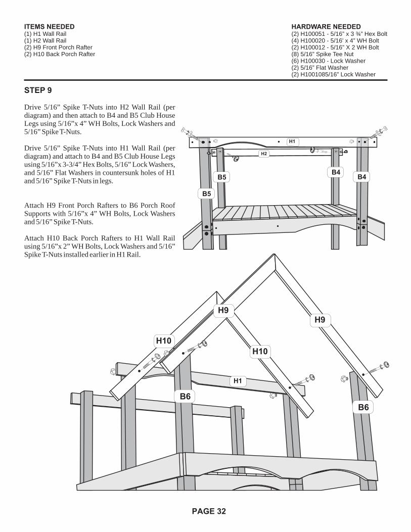
STEP 9
Drive 5/16” Spike T-Nuts into H2 Wall Rail (per diagram) and then attach to B4 and B5 Club House Legs using 5/16”x 4” WH Bolts, Lock Washers and 5/16” Spike T-Nuts.
Drive 5/16” Spike T-Nuts into H1 Wall Rail (per diagram) and attach to B4 and B5 Club House Legs using 5/16”x 3-3/4” Hex Bolts, 5/16” Lock Washers, and 5/16” Flat Washers in countersunk holes of H1 and 5/16” Spike T-Nuts in legs.
Attach H9 Front Porch Rafters to B6 Porch Roof Supports with 5/16”x 4” WH Bolts, Lock Washers and 5/16” Spike T-Nuts.
Attach H10 Back Porch Rafters to H1 Wall Rail using 5/16”x 2” WH Bolts, Lock Washers and 5/16” Spike T-Nuts installed earlier in H1 Rail.
B6
B6
H9H9
H10
H10
H1
ITEMS NEEDED(1) H1 Wall Rail(1) H2 Wall Rail(2) H9 Front Porch Rafter(2) H10 Back Porch Rafter
HARDWARE NEEDED(2) H100051 - 5/16” x 3 ¾” Hex Bolt(4) H100020 - 5/16' x 4” WH Bolt(2) H100012 - 5/16” X 2 WH Bolt(8) 5/16” Spike Tee Nut(6) H100030 - Lock Washer(2) 5/16” Flat Washer(2) H1001085/16” Lock Washer
H1
H2
B5
B5 B4B4

PAGE 33
STEP 10
Flush N8 Gable Board with peak of H9 Rafters and fasten with 1-1/4” Wood Screws (per diagram). Position N3 Gable Board Flat against bottom of N8 and secure to Rafters with 1-1/4” Wood Screws.
Position a N9 Gable Board on each side of N8 and fasten to rafters with 1-1/4” Wood Screws. Fasten K1 Gable Moon to N8, N9's and N3 with 1-1/4” Wood Screws.
N8
N9
N9
N3H9
H9
K1
B6
B6
ITEMS NEEDED(1) N8 Gable Board(1) N3 Gable Board(2) N9 Gable Board(1) K1 Gable Moon
HARDWARE NEEDED(15) 1 ¼” Wood Screws

PAGE 34
STEP 11
Attach N10 Gable Board to peak of H10 Rafters with 1-1/4” Wood Screws.
Attach R2R Front Right Porch Roof Board flush with H10 Rafter and with a 1-1/2” overhang on H9 front rafter and Flush at Peak using 1-1/2” Wood Screws.
Attach a R2L Front Left Porch Roof Board again flush with H10 and 1-1/2” overhang at H9 Rafter and flush to top of R2R installed previously with 1-1/2” Wood Screws.
Finish attaching nine (9) more roof boards on each side with 1-1/2” Wood Screws.
R2RR2LH9
H10 H10
H9
R2R
R2L
N10
1 1/2”
ITEMS NEEDED(10) R2L Roof Board(10) R2R Roof Board(1) N10 Gable Board
HARDWARE NEEDED(80) 1 ½” Wood Screws(4) 1 ¼” Wood Screws

PAGE 35
STEP 12
Attach H8 Club House Rafters to H1 and H2 Wall Rails with 5/16”x 2” WH Bolts, and Lock Washers into 5/16” Spike T-Nuts inserted in earlier step.
Attach a N10 Gable Board to peak of H8 Rafters using 1-1/4” Wood Screws.
Now attach N8, N3 and two (2) N9 Gable Boards and K1 Gable Moon to H8 Rafters on back side of structure using 1-1/4” Wood Screws as before on Step #10.
Now, attach a M5 Wall Rail Flush with Top of Clubhouse Legs on both the left and right side of structure with 5/16”x 2” Lag Screws and Lock Washers.
H8H8
H8
N9
N3K1
N9
N8
H1H2
H8H8
H8H8
H10 H10
H1
H2
N10
ITEMS NEEDED(4) H8 Club House Rafters(1) N10 Gable Board(1) N8 Gable Board(1) N3 Gable Board(2) N9 Gable Board(1) K1 Gable Moon
HARDWARE NEEDED(4) H100012 - 5/16” x 2” WH Bolt(4) 5/16” Spike Tee Nut(8) H100030 - Lock Washer(19) 1 ¼” Wood Screws(4) H100027 - 5/16” x 2” WH Lag Screw
M5
M5

PAGE 36
STEP 13
Attach a R1 Roof Board to peak of H8 Rafters with a 1-1/2” overhang on each end with 1-1/2” Wood Screws. Then, attach a R1 Roof Board on opposite side flush with top of R1 attached previously. Finish Roof attaching nine (9) more R1 Roof Boards to each side.
STEP 14Attach M5 Wall Rails to Left and Right side of structure by setting on Top of H11 Floor Rail and leveling across B2 and B3 Tower Legs and Fasten using 5/16”x 2” Lag Screws and Lock Washers. ( Pilot drill with 3/16”drill bit )
Now attach two (2) more M5 Wall Rails on Left and Right side by setting on top of M5 Wall Rails attached previously and level across B2 and B1 Tower Legs using 5/16”x 2” Lag Screws and Washers.Lock
R2RR2L
R1
R1
1-1/2”
H2
H8
H8
M5
M5M5
B1
B1
B2
B2
B3B3
H11
Other M5 not shown.
ITEMS NEEDED(20) R1 Roof Boards(4) M5 Wall Rails
HARDWARE NEEDED(8) H100027 - 5/16” x 2” WH Lag Screws(8) H100030 - Lock Washer(80) 1 ½” Wood Screw

PAGE 37
M7
M2
B3
B2
B3
BO
AR
D
FLATWASHER
BOLT
LOCKWASHER
BO
AR
D BARRELNUT
5/16"
5/16"
M2
M13”
B2B2
H5
M5 M5
BO
AR
D
FLATWASHER
BOLT
LOCKWASHER
BO
AR
D BARRELNUT
5/16"
5/16"
Diagram 1
Diagram 2
Diagram 3
STEP 15
Pilot Drill using 3/16” Drill Bit and attach M7 Wall Rail to B2 Middle Tower Leg flush with M5 (left side) with 5/16”x 2” Lag Screw and Lock Washer.
Attach M2 Wall Board to M7 with ¼”x 1” Phillips Truss Head Bolt with 5/16” Lock Washer, Washer and ¼” Barrel Nut.
Measure up 3” from top of floor and mark B2 Tower Legs and attach M1 Wall Rail to B2 Tower Legs with 5/16”x 2” Lag Screws and Lock Washers. ( Pilot drill with 3/16” drill bit)
Now, plumb M2 Wall Board and secure to M1 and G5 with 1-1/4” Wood Screws and to H5 Floor Rail with 1-1/4” Wood Screws.
Flush a M5 Wall Rail with M1 Wall Rail on both left and right side of structure and secure to B2 and B3 Tower Legs with 5/16”x 2” Lag Screws and Lock Washers.( Pilot drill with 3/16” drill bit )
Fender
Diagram 1
Diagram 2
Diagram 3
M5
G5
B2 B2
B3B3
M1
ITEMS NEEDED(1) M7 Wall Rail(1) M2 Wall Board(1) M1 Wall Rail(2) M5 Wall Rail
HARDWARE NEEDED(7) H100027 - 5/16” x 2” WH Lag Screw(2) Fender Washer(7) H100030 - Lock Washer(1) ¼” x 1” Phillips Truss Head Bolt
(1) ¼” Phillips Barrel Nut(6) 1 ¼” Wood Screws(1) H100108 - Lock Washer

PAGE 38
STEP 16
Flush H3 Wall Rail with M5 Wall Rails and attach to B3 Back Tower Legs with 5/16”x 2-3/8” Lag Screws and Lock Washers. ( Pilot drill with 3/16” drill bit note position of arch)
Attach H13 Wall Rail to H3 Wall Rail with 5/16”x 2” WH Bolt, Lock Washers and 5/16” Spike T Nut.
Attach M4 Wall Rail to H13 Wall Rail with 5/16”x 1-1/2 WH Bolt, Lock Washer and 5/16” Spike T-Nut and to B3 Back Tower Leg with 5/16”x 2” Lag Screw and Lock Washer.
Position Y30-40G L Bracket to H13 and use hole in bracket to mark floor. Drill thru floor board with 3/8” drill bit and finish securing H13 Wall Rail with Y30-40G using ¼”x 1” Phillips Truss Head Bolt, 5/16” Lock Washer, Washer and ¼” Barrel Nut and to Floor with ¾” Truss Head Bolt, 5/16” Lock Washer, Washer and 1/4” Barrel Nut.
Fender
Fender
H3
M4
H13
M5M5
B3
B3
LOCKWASHERBARREL
NUT
BOLT
FLOOR
FENDERWASHER
B3
H13
H13 H13
M4
H3
ITEMS NEEDED(1) H3 Wall Rail(1) H13 Wall Rail(1) M4 Wall Rail
HARDWARE NEEDED(1) Y30-40G L Bracket(1) ¼” x ¾” Phillips Truss Head Bolt(1) ¼” x 1” Phillips Truss Head Bolt(2) ¼” Phillips Barrel Nut(2) H100028 - 5/16” x 2 3/8” WH Lag Screw(4) Fender Washer(5) H100030 - Lock Washer(1) H100012 - 5/16” x 2” WH Bolt(1) H100027 - 5/16” x 2” WH Lag Screw(1) H100011 - 5/16” x 1 ½” WH Bolt(2) H100108 - 5/16” Lock Washer(2) H100074 - 5/16” Spike Tee Nut

PAGE 39
STEP 17
Begin by inserting four (4) 5/16” Spike T-Nuts into G8 Swing Beam Mount (per diagram). Then attach to B4 Clubhouse Legs on right side of structure with 5/16”x 4” WH Bolts, Lock Washers and 5/16” Spike T-Nuts.
B4
G8
B4
G8
B4
B4
G8
ITEMS NEEDED(1) G8 Swing Beam Mount
HARDWARE NEEDED(8) 5/16” Spike Tee Nut(4) H100020 - 5/16” x 4” WH Bolt(4) H100030 - Lock Washer

PAGE 40
STEP 18
(Pilot drill with 3/16” drill bit when using Lag Screws)
Attach M1 Wall Rail to B4 and B5 Club House Legs with 5/16”x 2” WH Lag Screws, Lock Washers flush with bottom of G8.
Now attach M5 Wall Rail to B5 Clubhouse Legs on left side of Structure using 5/16”x 2” Lag Screws, and Lock Washers.
Now, attach a M5 Wall Rail Flush with Top of Clubhouse Legs on both the left and right side of structure with 5/16”x 2” Lag Screws and Lock Washers.
H2
M1
M5
B4B5
B5
B4
M5
M5
B4 B5B4 B5
Top Floor
M1M5
G8
ITEMS NEEDED(1) M1 Wall Rail(3) M5 Wall Rail
HARDWARE NEEDED(4) H100027 - 5/16” x 2” WH Lag Screw(4) H100030 - Lock Washer

PAGE 41
STEP 19
Attach H14 Top Wall Rail to H1 Wall Rail with 5/16”x 2” WH Bolt, Lock Washer and 5/16” Spike T-Nut and secure with a Y30-40G L-Bracket using ¼”x 1” Phillips Truss Head Bolt, 5/16” Lock Washer, Washer and ¼” Barrel Nut and to Floor with a ¾” Truss Head Bolt, 5/16” Lock Washer, Washer and 1/4” Barrel Nut. Position L Bracket to H14 and use hole in bracket to mark floor and drill with 3/8” drill bit.
Attach M5 Wall Rail to H14 using 5/16”x 1-3/4” WH Bolt, Lock Washer and 5/16” Spike T-Nut and to B4 Clubhouse Leg with 5/16”x 2” WH Lag Screw and Lock Washer.
( Pilot drill with 3/16” drill bit )
FenderFender
M5
H1
H14
LOCKWASHERBARREL
NUT
BOLT
FLOOR
FENDERWASHER
H14H14
ITEMS NEEDED(1) H14 Top Wall Rail(1) M5 Wall Rail
HARDWARE NEEDED(1) Y30-40G L Bracket(1) H100012 - 5/16” x 2” WH Bolt(1) H100011 - 5/16” x 1 1/2” WH Bolt(2) 5/16 Spike Tee Nut(2) ¼” Phillips Barrel Nut(1) ¼” x 1” Phillips Truss Head Bolt(1) ¼” x ¾” Phillips Truss Head Bolt(1) H100027 - 5/16” x 2” WH Lag Screw(4) Fender Washer(3) H100030 - Lock Washer(2) H100108 - Lock Washer

PAGE 42
STEP 20
Attach H16 Front Wall Rail to G4 Wall Rail with 5/16”x 2” WH Bolts, Lock Washers and 5/16” Spike T-Nut. Position L Bracket to H16 and mark floor and drill with 3/8” drill bit.
Now, secure H16 to Floor with Y30-40G L-Bracket using ¼”x 1” Phillips Truss Head Bolt, 5/16” Lock Washer, Washer and ¼” Barrel Nut and to Floor with ¾” Truss Head Bolt, 5/16” Lock Washer, Washer and 1/4” Barrel Nut.
FenderFender
LOCKWASHERBARREL
NUT
BOLT
FLOOR
FENDERWASHER
H16
H16
G4
B1B1
G4
ITEMS NEEDED(1) H16 Front Wall Rail
HARDWARE NEEDED(1) Y30-40G L Bracket(1) H100012 - 5/16” x 2” WH Bolt(1) 5/16” Spike Tee Nut(2) ¼” Phillips Barrel Nut(1) ¼” x 1” Phillips Truss Head Bolt(1) ¼” x ¾” Phillips Truss Head Bolt(4) Fender Washer(1) H100030 - Lock Washer(2) H100108 - Lock Washer
Pre-drill hole in H16using 5/16” drill bit

PAGE 43
STEP 21
Attach N1 Wall Rail to inside H8 Club House Rafter 3” up from H2 Wall Rail with 1-1/4” Wood Screws.
N1
3”
H2
H8 H8
ITEMS NEEDED(1) N1 Wall Rail
HARDWARE NEEDED(2) 1 ¼” Wood Screws

STEP 22
( Pilot drill with 3/16” drill bit when using Lag Screws )
Attach T1 Picnic Table Support flush with bottom of H6 Floor Rail and 18-1/4” from edge of H6 with 1-1/2” Wood Screws. Attach M5 Wall Rail to B1 and B2 Tower Legs by pushing up against Bottom of H11 Floor Rail with 5/16”x 2” WH Lag Screws and Lock Washers.
PAGE 44
T1
M5
H6
18-1/4”
G7
G7
B1
B1
B2
H11
ITEMS NEEDED(1) T1 Picnic Table Support(1) M5 Wall Rail
HARDWARE NEEDED(5) 1 ½” Wood Screw(2) H100027 - 5/16” x 2” WH Lag Screw(2) H100030 - Lock Washer

STEP 23
Attach H15 Picnic Table Support to G6 Base Board with 5/16”x 2” WH Bolts, Lock Washers and 5/16” Spike T-Nuts. Attach H17 Picnic Table Top Support to H15 with 5/16”x 2” WH Bolts, 5/16” Lock Washers, Washers and 5/16” Spike T-Nuts.
Attach H20 Picnic Table Seat Support to H19 Picnic Table Seat Legs with 5/16”x 2” WH Bolts, Lock Washers and 5/16” Spike T-Nuts. You will make two lefts and two rights (per diagram).
Now, fasten Picnic Table Seat Support assemblies to B1 and B2 Tower Legs using 5/16”x 2-3/8” WH Lag Screws and Lock Washers. Finish attaching Seat Supports to G7 and G6 with 5/16”x 1-1/2” WH Lag Screws and Lock Washers.
Fender
PAGE 45
H15
H17
H20H20
H19
H19
G7
B1B1B2
B2
G6
ITEMS NEEDED(1) H15 Picnic Table Support(1) H17 Picnic Table Top Support(4) H19 Picnic Table Seat Legs(4) H20 Picnic Table Seat Clamps
HARDWARE NEEDED(12) H100012 - 5/16” x 2” WH Bolt(4) H100028 - 5/16” x 2 3/8” WH Lag Screw(8) H100026 - 5/16” x 1 ½” WH Lag Screw(12) 5/16” Spike Tee Nut(24) H100030 - Lock Washer

STEP 24
Attach H21 Picnic Table Supports to H15 with 2” Wood Screws and H17 with 1-1/2” Wood Screws.
Attach H12 Picnic Table Seats to Picnic Table Seat Supports with 2” Wood Screws.
Attach seven (7) M8 Picnic Table Boards with 1-1/4” Wood Screws.
Finish Table by Fastening N6 Picnic Table Support under and middle of M8 Picnic Table Boards with 1-1/4” Wood Screws.
PAGE 46
H15
H17
H21
H12
M8
H12
N6
1-1/2”
2”
ITEMS NEEDED(2) H21 Picnic Table Support(4) H12 Picnic Table Seats(7) M8 Picnic Table Boards(1) N6 Picnic Table Support
HARDWARE NEEDED(35) 1 ¼” Wood Screws(4) 1 ½” Wood Screws(18) 2” Wood Screws

STEP 25
Attach M9 Wall Boards to inside of Wall Rails on left, right and Back Walls 3” apart and 1-1/2” up from M5 and M4 Rail with 1-1/4” Wood Screws. Diagram 1
Attach M10 Wall Boards to inside Back Wall 1-1/2” up and 2-1/4” apart using 1-1/4” Wood Screws. (Note: Start at Tower Legs and work to middle on Lower and Upper Wall.) Diagram 2
Attach M10 Wall Boards to middle Floor Wall Rails 1-1/2”up From Wall Rail and 3” apart using 1-1/4” Wood Screws, to Right and Left Sides. Diagram 3
PAGE 47
M10
M10
1 ½” upfrom bottom of rail
2 ¼” spacing
M10M10
1 ½” upfrom bottom of rail
3” spacing
M9
M4
M5
1 ½” upfrom bottom of rail
3” spacing
Diagram 1
Diagram 2
Diagram 3
ITEMS NEEDED(12) M9 Wall Boards(20) M10 Wall Boards
HARDWARE NEEDED(128) 1 ¼” Wood Screws

STEP 26
Using the existing holes in the O1 Wall Rail as a guide, drill the holes using a 3/8” drill bit. Measure Up 11-1/4” from Top of G4 Wall Rail and bottom of O1 Wall, using the holes in the O1 as a guide drill two 3/16” pilot holes into the B1 Tower Legs. Attach the O1 Wall Rail to the B1 Front Tower Legs using 2” WH Lag Screws and Lock Washers.
Now, attach O3 Wall Boards to O1 and G4, spacing them 2-5/16” apart and Flush with top of O1 with 1-1/4” Wood Screws.
PAGE 48
O1
O3
G4
11 ¼”
2 5/16” spacing
B1B1
O1
ITEMS NEEDED(1) O1 Wall Rail(14) O3 Wall Boards
HARDWARE NEEDED(28) 1 ¼” Wood Screws(2) H100027 - 5/16” X 2” WH Lag Screws(2) H100030 - Lock Washer

STEP 27
Attach four M9 Wall Boards to Wall Rails at Left and Right and eight to Back and four more to inside Back Walls. Flush at Bottom of Rails and 3” apart with 1-1/4” Wood Screws.
PAGE 49
Right Side And Inside Back Wall Not Visible
ITEMS NEEDED(20) M9 Wall Boards
HARDWARE NEEDED(80) 1 ¼” Wood Screws
M9M9
3” apart

STEP 28
Start Rock Wall by attaching Rocks to L1 Rock Wall Boards and L2 Rock Wall Boards, using ¼”x ¾” Phillips Truss Head Bolts, 5/16” Lock Washers, Fender Washers and ¼” Barrel Nuts. Diagram 1
Set E3L Rock Wall Rail and E3R Rock Wall Rail against Tower and from Bottom attach L3, then L1, then L2 and continue to top and fasten using 1-1/2” Wood Screws.
Position Rock Wall to Floor Rail and pilot drill E3L and E3R with 3/16” Bit and attach Rock Wall to Floor Rail using 5/16”x 2” WH Lag Screws and Lock Washers. Diagram 3
Attach O2 Rock Wall Spacer between and Flush with top of E3L and E3R using 1-1/4” Wood Screws. Finish Wall with SC2 Rock Wall Board. Diagram 2
PAGE 50
BOLT
5/16”LOCK
WASHER
ROCK
BO
AR
D
FENDERWASHER
BARRELNUT
Use 1/4” x 3/4” Phillips Truss Head Bolt with 5/16” Lock Washer. Then place Washer on Barrel Nut and attach Rock to each board.
Fender
Diagram 1
E3L
E3R
L3
L1
L2
O2
SC2
Diagram 2
Diagram 3
ITEMS NEEDED(5) L3 Rock Wall Boards(1) E3L Rock Wall Rail(1) E3R Rock Wall Rail
(1) SC2 Rock Wall Board(1) O2 Rock Wall Spacer(4) L1 Rock Wall Boards(4) L2 Rock Wall Boards(12) Rocks
HARDWARE NEEDED(3) 1 ¼” Wood Screws(56) 1 ½” Wood Screws(2) H100027 - 5/16” x2” WH Lag Screws(2) H100030 - Lock Washer(24) H100108 Lock Washer
(24) H100105 Fender Washer(24) ¼” Phillips Barrel Nut(24) ¼” x ¾” Phillips Truss Head Bolt

STEP 29
Attach four (4) Swing Hangers to A1 Swing Beam with 3/8”x 5-3/4” Hex Bolts, 3/8” Lock Washers, 3/8” Flat Washers and 3/8” Spike T-Nuts. Now attach Glider Supports to A1 Swing Beam using 5/16”x 5” WHA Bolts, Fender Washers, Lock Washers and 5/16” WHA Barrel Nuts.
Attach A100004 Swing Beam Bracket to A1 with 5/16” x 4” WH Bolts, Fender Washers and Lock Nuts. Attach A100005 Triangle Brace to A1 using 5/16”x 4” WH Bolts, Fender Washers and 5/16” Lock Nut.
Attach E1 Angle Braces to SP 1 Beam Support with 3/8”x 6-1/2” WH Bolt, 3/8” Lock Washer, 3/8” Flat Washer and 3/8” Spike T-Nut. (Note: Refer to Diagram for inserting spike T-Nut into counter-sunk hole).
Attach E2 Beam End Support to SP1 and E1 angle braces using 5/16”x 3” WH Lag Screws and Lock Washers to SP1 and 5/16”x 2-3/8” WH Lag Screws and Lock Washers to E1 Angle Braces.
Attach G1 Ground Board to E1 Angle Braces with 5/16”x 2” WH Lag Screws and Lock Washers.
Now attach Swing Beam Support assembly to Swing Beam using 5/16”x 4” Hex Bolts, Fender Washers and 5/16” Lock Nuts.
PAGE 51
A1A100005
A100004
Use any convenient long 3/8" bolt.
ITEMS NEEDED(1) A1 Swing Beam(1) SP1 Beam Support(1) E2 Beam End Support(2) E1 Angle Braces(1) G1 Ground Board
HARDWARE NEEDED(2) Glider Supports (Y25G)(2) Triangle Braces (A100005)(2) L Braces (A100004) Swing Beam Mount(4) Swing Hangers (Y40-HD4)(6) 5/16” Lock Nuts(6) H100020 - 5/16” x 4” WH Bolts
(8) 3/8” x 5 ¾” Hex Bolts(9) 3/8” Flat Washer(9) 3/8” Lock Washer(9) 3/8” Spike Tee Nut(2) H100029 - 5/16” x 3” WH Lag Screw(4) H100027 - 5/16” x 2” WH Lag Screw(2) H100028 - 5/16” x 2 3/8” WH Lag Screw
(1) 3/8” x 6 1/2” WH Bolt(4) H100022 - 5/16” x 5” WH Bolt(4) 5/16” WH Barrel Nut(8) H100030 - Lock Washer(4) H100031 - Lock Washer(6) H100105 - Fender Washer
5” WHA BoltLock Washers
& Fender Washers
H100031 Lock WasherBarrel NutsWHA
SP1
E1
E1
G1
E2
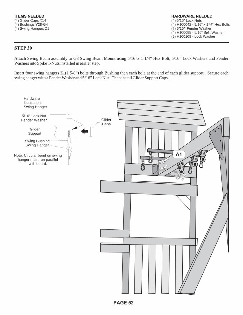
STEP 30
Attach Swing Beam assembly to G8 Swing Beam Mount using 5/16”x 1-1/4” Hex Bolt, 5/16” Lock Washers and Fender Washers into Spike T-Nuts installed in earlier step.
Insert four swing hangers Z1(1 5/8”) bolts through Bushing then each hole at the end of each glider support. Secure each swing hanger with a Fender Washer and 5/16” Lock Nut. Then install Glider Support Caps.
PAGE 52
A1
HardwareIllustration:Swing Hanger
Glider Support
5/16” Lock NutFender Washer Glider
Caps
Swing BushingSwing Hanger
Note: Circular bend on swinghanger must run parallel
with board.
ITEMS NEEDED(4) Glider Caps X14(4) Bushings Y28-G4(4) Swing Hangers Z1
HARDWARE NEEDED(4) 5/16” Lock Nuts(4) H100042 - 5/16” x 1 ¼” Hex Bolts(8) 5/16” Fender Washer(4) H100095 - 5/16” Split Washer(5) H100108 - Lock Washer

STEP 31
Construct Entry Ladder using 2” Wood Screws thru E4L and E4R into H18 Ladder Steps. Attach N7 Ladder back3” down from angle point on top of ladder rails with 1-1/4” Wood Screws.
Now build two (2) identical ladders using E5L and E5R Entry Ladder rails with 2” Wood Screws thru Ladder rails into H18 Ladder Steps. Attach N7 Entry Ladder Back to the bottom of E5L and E5R Entry Ladder rails with 1-1/4" Wood Screws.Note: (Pilot Drill Entry ladder Rails with 3/16” Drill bit.) Attach Entry ladders to Floor Rails using 5/16”x 2” WH Lag Screws and Lock Washers.
PAGE 53
E4L E4R
E5L
E5R
E4L E4R
E5L E5R
H18H18
H18H18
H18
H18
H18
N7
N7
N73”
Down
3”Down
E5L E5R
G5
ITEMS NEEDED(1) E4L Entry Ladder Rail (1) E4R Entry Ladder Rail (2) E5L Entry Ladder Rail (2) E5R Entry Ladder Rail (6) H18 Ladder Steps(3) N7 Entry Ladder Back
HARDWARE NEEDED(24) 2” Wood Screw(6) 1 ¼” Wood Screw(6) H100027 - 5/16” x 2” WH Lag Screw (6) H100030 - Lock Washer
N7
N7

STEP 32
Attach Y10-16.5G Metal Grips to H16 Front Wall Rail (Figure 1) using ¼”x ¾” Phillips TrussHead Bolts, 5/16” Lock Washers, Fender Washers and ¼” Barrel Nuts. Position another Y10-16.5G Grip on B1 Front Tower Leg and attach using 5/16”x 1-1/2” WH Lag Screws and Lock Washers. Now attach Y10-16.5 Grips to H13 Back Wall Rail (Figure 2) and B3 Back Tower Leg and H14 Top Wall Rail and B5 Clubhouse leg with same Hardware used on Grips installed on front of Tower.
PAGE 54
B3
H13
M2
Figure 1
Figure 2
B5
ITEMS NEEDED(8) Y10-16.5G
HARDWARE NEEDED(8) H100026 - 5/16” x 1 ½” WH Lag Screw(8) ¼” Phillips Barrel Nut(8) ¼” x ¾” Phillips Truss Head Bolt(16) Fender Washer(16) 5/16” Lock Washer
H14
B2
H16
B1
10 1/2"
(1)-1/4" Phillips Barrel Nut(1)-5/16" Lock Washer(2)-Fender Washers
(1)-1/4" x 3/4" PTH Bolt(2)-Fender Washers
Attach Y10-16.5G Metal Grips to M2 Wall Board (Figure 3) using ¼”x ¾” Phillips Truss Head Bolts, 5/16” Lock Washers, Fender Washers and ¼” Barrel Nuts. Position another Y10-16.5G Grip on B2 Middle Tower Leg and attach using 5/16”x 1-1/2” WH Lag Screws and Lock Washers.
Figure 3

STEP 33
Installing the Steering Wheel and Telescope you may prefer to relocate, but this is where we installed for reference.
Use a 3/16” Drill bit to pilot drill wall rail and attach Steering Wheel with 5/16”x 1-1/2” WH Lag Screw and Flat Washer.
Attach Telescope base to top of Wall Rail with 1-1/2” Wood Screws and Then snap Telescope into base.
PAGE 55
ITEMS NEEDED(1) Steering Wheel 5137-1(1) Telescope 5147-1
HARDWARE NEEDED(1) H100026 - 5/16” x 1 ½” WH Lag Screw(2) 1 ½” Wood Screw

STEP 34
Assemble Glider using 5/16”x 5-3/4” Hex Bolts, Fender Washers and Lock Nuts. Then attach 57” chains to Glider Handles using Quick Links. Then hang Glider from Swing Hangers and tighten Quick Links on Swing Hangers and Glider ends.
Attach 62” chains to Swing Belts using Quick Links and tighten; then hang with Carabiners and Safety tubes to Swing Hangers.
Tighten the quick link with a wrench. The quick link must be tightened so that it cannot be opened by hand.
PAGE 56
Flat WasherLock Nut
5 3/4 Hex BoltFlat Washer
Tighten QuickLink
Insert Chain IntoQuick Link
• Slip the Plastic SafetyTubes on the Carabiner.
ITEMS NEEDED(2) Swing Seats(8) Quick Links (2 Bags of 4) ZQLB1(4) 57” Chains Y60-57G(4) 62” Chains Y60-62G(1) Ships Wheel Glider (1) Seat, (2) Ends X11-Cay
HARDWARE NEEDED(2) 5/16” x 5 ¾” Hex Bolts(4) Flat Washer(2) 5/16” Lock Nut(4) Carabiner(4) Plastic Safety Tubes

O4
Flush
STEP 35
Pilot drill 04 Slide Board with 3/16” drill bit and Attach O4 Slide Board to Floor Boards using 1-1/4” Wood Screws. Position O4 –flush with front floor Rail and 6-1/4” From Left Side Floor Rail (Per Diagram). Now, position Slide over O4 and using holes in slide mark Floor Boards, remove Slide and Drill thru Floor Board with a 3/8” Drill Bit. Set Slide back on set and attach using Step Bolts thru Slide and 5/16” Lock Washers, Fender Washers and 1/4” Barrel Nuts from under Floor Boards.
PAGE 57
1/4"BARREL
HEADNUT
1/4 X 1"STEPBOLT
5/16"INTERNAL
TOOTHLOCK
WASHER
FENDERWASHER
SLIDE
WOOD FLOOR
BOLT
5/16" LOCK WASHER
FENDER WASHER
BARREL NUT
O4
STEP 36
Attach ID Plate to center of A1 Swing Beam with 1-1/4” Wood Screws.
Install Ground anchors to G1 Ground Board on Swing Beam (Per Diagram).
Measure in 6” from outside edge of G1 Ground Board and mark ground. Using screw driver screw stake into ground until 3” from top of G1 Ground Board. Use hole in stakes to drill 3/8” hole and attach stakes to Ground Board using 1” Phillips Truss Head Bolts, Fender Washers, 5/16” Lock Washers and 5/16” Barrel Nuts.
Metal Stake
FENDERWASHER
BOLT
LOCKWASHER
BO
AR
D
FENDERWASHER
BARRELNUT
5/16"
G1
PRODUCTSSILOAM SPRINGS, AR 72761
PHONE 866-362-1123
TH 0IS 1 P LA TOYS 2ET ES IS AG INT EN ENDE ILDRD FOR CH
ITEMS NEEDED(1) O4 Slide Board(1) 10' Slide(1) ID Plate Y50-LTP(2) Ground Stakes Y41
HARDWARE NEEDED(3) ¼” x 1” Step Bolts(5) ¼” Phillips Barrel Nut(7) Fender Washer(5) H100108 - Lock Washer(2) 1 ¼” Wood Screw
(2) ¼” x 1” Phillips Truss Head Bolt

Limited Warranty
This Limited Warranty by Backyard Discovery applies to products manufactured under the Backyard Discovery brand or its other brands including but not limited to Backyard Botanical, Adventure Playsets, and Leisure Time Products.
Backyard Discovery warrants that this product is free from defect in materials and workmanship for a period of one (1) year from the original date of purchase. This one (1) year warranty covers all parts including wood, hardware, and accessories. All wood carries a five (5) year pro-rated warranty against rot and decay. Refer to the schedule below for charges associated with replacement of parts under this Limited Warranty. In addition, Backyard Discovery will replace any parts within the first 30 days from date of purchase found to be missing from or damaged in the original packaging.
This warranty applies to the original owner and registrant and is non-transferable. Regular maintenance is required to assure maximum life and performance of this product and failure by the owner to maintain the product according to the maintenance requirements may void this warranty. Maintenance guidelines are provided in the Owner's Manual.
This Limited Warranty does not cover:
• Labor for any inspection• Labor for replacement of any defective item(s)• Incidental or consequential damages• Cosmetic defects which do not affect performance or integrity of a part or the entire product• Vandalism, improper use, failure due to loading or use beyond the capacities stated in the applicable
Assembly Manual.• Acts of nature including but not limited to wind, storms, hail, floods, excessive water exposure• Improper installation including but not limited to installation on uneven, unlevel, or soft ground• Minor twisting, warping, checking, or any other natural occurring properties of wood that do not affect performance
or integrity
Backyard Discovery products have been designed for safety and quality. Any modifications made to the original product could damage the structural integrity of the unit leading to failure and possible injury. Modification voids any and all warranties and Backyard Discovery assumes no liability for any modified products or consequences resulting from failure of a modified product.
This product is warranted for RESIDENTIAL USE ONLY. Under no circumstance should a Backyard Discovery product be used in public settings. Such use may lead to product failure and potential injury. Any and all public use will void this warranty. Backyard Discovery disclaims all other representations and warranties of any kind, express or implied.
This Warranty gives you specific legal rights. You may have other rights as well which vary from state to state or province to province. This warranty excludes all consequential damages, however, some states do not allow the limitation or exclusion of consequential damages and therefore this limitation may not apply to you.
Pro Rated Part Replacement Schedule
Product Age Customer PaysAll Parts0-30 days from date of purchase $0 and free shipping31 days to 1 year $0 + S&H
Wood Rot and Decay Only1 year $0 and free shipping2 years 20% + S&H3 years 40% + S&H4 years 60% + S&H5 years 80% + S&HOver 5 years 100% + S&H
PAGE 58

Garantía limitada
Esta garantía limitada de Backyard Discovery se aplica a productos fabricados bajo la marca Backyard Discovery o sus otras marcas incluyendo a título informativo pero no limitativo Backyard Botanical, Adventure Playsets, y Leisure Time Products.
Backyard Discovery garantiza que este producto no tiene defectos de material ni de mano de obra durante el período de un (1) año a partir de la fecha original de compra. Esta garantía de un (1) año ampara todas las piezas incluyendo la madera, los herrajes, y accesorios. La madera tiene una garantía prorrateada de cinco (5) años contra la descomposición y el deterioro. Refiérase a la tabla que sigue para los cargos relacionados con el reemplazo de las piezas bajo esta garantía limitada. Adicionalmente Backyard Discovery reemplazará cualesquiera piezas que faltaren en el empaque original o estuviesen dañadas dentro de los primeros 30 días a partir de la fecha de compra.
Esta garantía se aplica al propietario original y al registrante y no es transferible. El mantenimiento regular es un requisito para lograr el máximo de vida útil y rendimiento de este producto. Si el propietario no presta el mantenimiento conforme a los requisitos puede anularse la garantía. Las pautas de mantenimiento se indican en el Manual del Propietario.
Esta garantía limitada no ampara:
• Mano de obra por cualquier inspección.• Mano de obra para el reemplazo de cualesquiera piezas defectuosas.• Daños accidentales o resultantes• Defectos de orden cosmético que no afecten el rendimiento o integridad de una pieza o del producto completo.• Vandalismo, uso inadecuado, fallas debido a la carga o el uso que excedan las capacidades establecidas
en el Manual de Ensamblaje correspondiente.• Actos de la naturaleza que incluyen, a título informativo más no limitativo, viento, tormentas, granizo,
inundaciones, excesiva exposición al agua.• Instalación inadecuada incluyendo a título informativo más no limitativo, la instalación en tierra
dispareja, desnivelada o poco compacta.• Torceduras menores, deformaciones, fisuras o cualquier otra característica natural de la madera que
no afecte el rendimiento o la integridad.
Los productos de Backyard discovery han sido diseñados para brindar seguridad y calidad. Cualquier modificación que se haga al producto original podría dañar la integridad estructural de la unidad lo cual podría conducir a fallas y la posibilidad de lesiones. La modificación anula cualquiera garantía en particular y todas las garantías en general y Backyard Discovery no asume responsabilidad por cualquier producto modificado ni por las consecuencias que resultaren de la falla de un producto modificado.
Este producto está garantizado para USO RESIDENCIAL ÚNICAMENTE. Bajo ninguna circunstancia debe utilizarse un producto Backyard Discovery en lugares públicos tales. Tal uso podría ocasionar falla del producto y lesiones potenciales. El uso público anulará esta garantía. Backyard Discovery desconoce toda otra representación o garantía de cualquier índole, expresa o implícita.
Esta garantía le otorga derechos legales específicos. También podría gozar de otros derechos, los cuales varían de un estado a otro o de una provincia a otra. Esta garantía excluye todos los daños resultantes. Sin embargo, algunos estados no permiten la limitación o exclusión de los daños resultantes, por lo tanto es posible que esta limitación no aplique en su caso.
Tabla prorrateada de reemplazo de piezas
Edad del producto El cliente pagaTodas las piezas0-30 días a partir de la fecha de compra $0 y envío gratis31 días a 1 año $0 + envío y manejo
Descomposición y deterioro de la madera únicamente1 año $0 y envío gratis2 años 20% + Envío y manejo3 años 40% + Envío y manejo4 años 60% + Envío y manejo5 años 80% + Envío y manejoMás de 5 años 100% + Envío y manejo
PAGE 59
Bac
kya
rd D
isco
very
War
ran
ty R
egis
trat
ion
Car
dT
arje
ta d
e in
scri
pció
n d
e ga
ran
tia
de B
acky
ard
Dis
cove
ry
Ple
ase
fill
out
thi
s im
port
ant
info
rmat
ion
abou
t yo
ur p
urch
ase
and
drop
it
in t
he n
eare
st m
ailb
ox. W
e pa
y th
e po
stag
e!
Por
fav
or l
lene
est
a im
port
ante
inf
orm
ació
n so
bre
su c
ompr
a y
coló
quel
a en
el
buzó
nm
ás c
erca
no. ¡
Nos
tros
pag
amos
el
fran
queo
!
Pre
fer
to r
egis
ter
onli
ne?
/ ¿P
refi
ere
insc
ribi
rse
a tr
avés
de
Inte
rnet
?
ww
w.s
win
gset
sonl
ine.
com
/reg
iste
r
Par
ent/
Ow
ner
(Pad
re/m
adre
/pro
piet
ario
):
Str
eet A
ddre
ss/D
irec
ción
de
dom
icil
io:
Cit
y/C
iuda
d:
S
tate
/Est
ado:
Z
ip/C
ódig
o po
stal
:
Em
ail A
ddre
ss/D
irec
ción
de
corr
eo e
lect
róni
co:
Pho
ne/T
eléf
ono:
(
)
-
Pur
chas
ed F
rom
/Com
prad
o en
:
D
ate
Pur
chas
ed/F
echa
de
com
pra:
Mod
el N
ame/
Núm
ero
de m
odel
o:

BU
SIN
ES
S R
EP
LY M
AIL
FIR
ST-C
LAS
S M
AIL
PO
STA
GE
WILL B
E PA
ID B
Y A
DD
RE
SS
EE
NO
PO
STA
GE
NE
CE
SS
AR
YIF
MA
ILED
IN T
HE
UN
ITE
D S
TATE
S
PE
RM
IT N
O. 6
PIT
TS
BU
RG
, KS
CU
STO
ME
R S
ER
VIC
E M
AN
AG
ER
BA
CK
YAR
D D
ISC
OV
ER
YP
O B
OX
324P
ITT
SB
UR
G, K
S 66762-9908
NO
PO
STA
GE
NE
CE
SS
AR
YIF
MA
ILED
IN T
HE
UN
ITE
D S
TATE
S