highly compliant riser large scale model test joint
TRANSCRIPT
Highly Compliant Riser
Large Scale Model Test
Joint Industry Project
Data Reduction and Report
Prepared
for
PMB Engineering
50 Beale Street
San Francisco, CA 94105
Prepared
by
Scientific Marine Services, Inc.
101 State Place
Suite N
Escondido, CA 92029

, Scientific Marine Services, Inc. v
10 1 State Place, Suite N Escondido, CA 92029 Tel: (760) 737-3505 Fax: (760) 737-0232
PMB Engineering 50 Beale Street San Francisco. CA 94105
04 December 1998
Attention: Robert Grant
Subject: Draft Final Report for HCR-JIP
Dear Bob, .A.,
The following are two copies of the draft final report on the base HCR test program, and the Raw Data, Processed Data, and Hard Bottom CD-ROMs that go with it. The hard bottom addendum will follow shortly.
In accordance with your instructions, we have also sent copies to the participants on the list you sent, with the appropriate CDs.
Regards,
Vice President encl.: report and CD:


Highly Compliant Riser
Large Scale Model Test
Joint Industry Project
Data Reduction and Report SMS Project 97-504 4 December 1998
Prepared
for
PMB Engineering
50 Beale Street
San Francisco, CA 94105
Prepared
by Scientific Marine Services, Inc.
101 State Place
Suite N
Escondido, CA 92029


Scientific Marine Services, Inc. Escondido, CA 92029
December 1998 HCR JIP Riser Test Report Rev. 1.0
Prepared By
Frederick H. Ashcroft Deputy Project Manager
Reviewed By
Project Manager

Scientific Marine Services. Inc . Escondido. CA 92029
December 1998 HCR JIP Riser Test Report Rev . 1.0
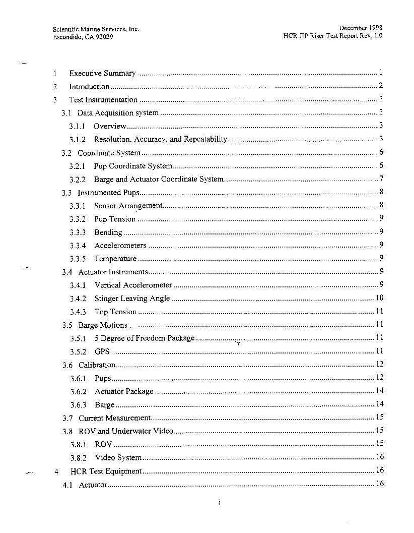
..................................................................................................................... 1 Executive Summary 1
2 Introduction .................................................................................................................................. 2
3 Test Instrumentation ................................................................................................................. 3
3.1 Data Acquisition system ......................................................................................................... 3
3.1.1 Overview ......................................................................................................................... 3
......................................................................... 3.1.2 Resolution. Accuracy. and Repeatability 3
................................................................................................................... 3.2 Coordinate System 6
3.2.1 Pup Coordinate System .................................................................................................... 6
3.2.2 Barge and Actuator Coordinate System ........................................................................... 7
3.3 Instrumented Pups ................................................................................................................ 8
......................................................................................................... 3.3.1 Sensor Arrangement 8
..................................................................................................................... 3.3.2 Pup Tension 9
3.3.3 Bending ........................................................................................................................ 9 7 7 ................................................................................................................ 2.2 4 Accelerometers 9
..................................................................................................................... 3.3.5 Temperature 9
3.4 Actuator Instruments ................................................................................................................ 9
3.4.1 Vertical Accelerometer ................................................................................................. 9
................................................................................................... 3.4.2 Stinger Leaving Angle 10
................................................................................................................... 3.4.3 Top Tension 11
3.5 Barge Motions ....................................................................................................................... 11
....................................................................................... 3.5.1 5 Degree of Freedom Package 11 '7
3.5.2 GPS ................................................................................................................................ 11
3.6 Calibration .............................................................................................................................. 12
3.6.1 Pups ................................................................................................................................ 12
........................................................................................................... 3.6.2 Actuator Package 14
3.6.3 Barge .............................................................................................................................. 14
............................................................................................................. 3.7 Current Measurement 15
.................................................................................................. 3.8 ROV and Underwater Video 15
3.8.1 ROV .............................................................................................................................. 15
................................................................................................................. 3.8.2 Video System 16
................................................................................................................. ..- 4 HCR Test Equipment 16
4.1 Actuator ................................................................................................................................. 16
i

Scientific Marine Services. Inc . Escondido. C A 92029
December 1998 HCR JIP Riser Test Report Rev . 1.0
...................................................................................... 7.3.7 Analysis of Specific Examples 52
7.3.8 Description of File Formats ......................................................................................... 53
7.3.9 Extracting Specific Test Runs From the CD-ROM Files .............................................. 54
........................................................................................ 8 Commentary on System Performance 55
..................................................................................................... 8.1 Riser Handling Equipment 55
.................................................................................................................................. 8.2 Actuator 55 . . .
8.3 Data Acquisltlon System ....................................................................................................... 55
...................................................................................................................... 8.4 Instrumentation 55
8.5 GPS .................................................................................................................................... 55
.......................................................................................... 9 Recommendations for Improvement 56
9.1 Equipment .............................................................................................................................. 56
9.2 ROV ....................................................................................................................................... 56
9.3 Data Acquisition .................................................................................................................. 56
Scientific Marine Services. Inc . Escondido. CA 92029
December 1998 HCR JIP Riser Test Report Rev . I . 0
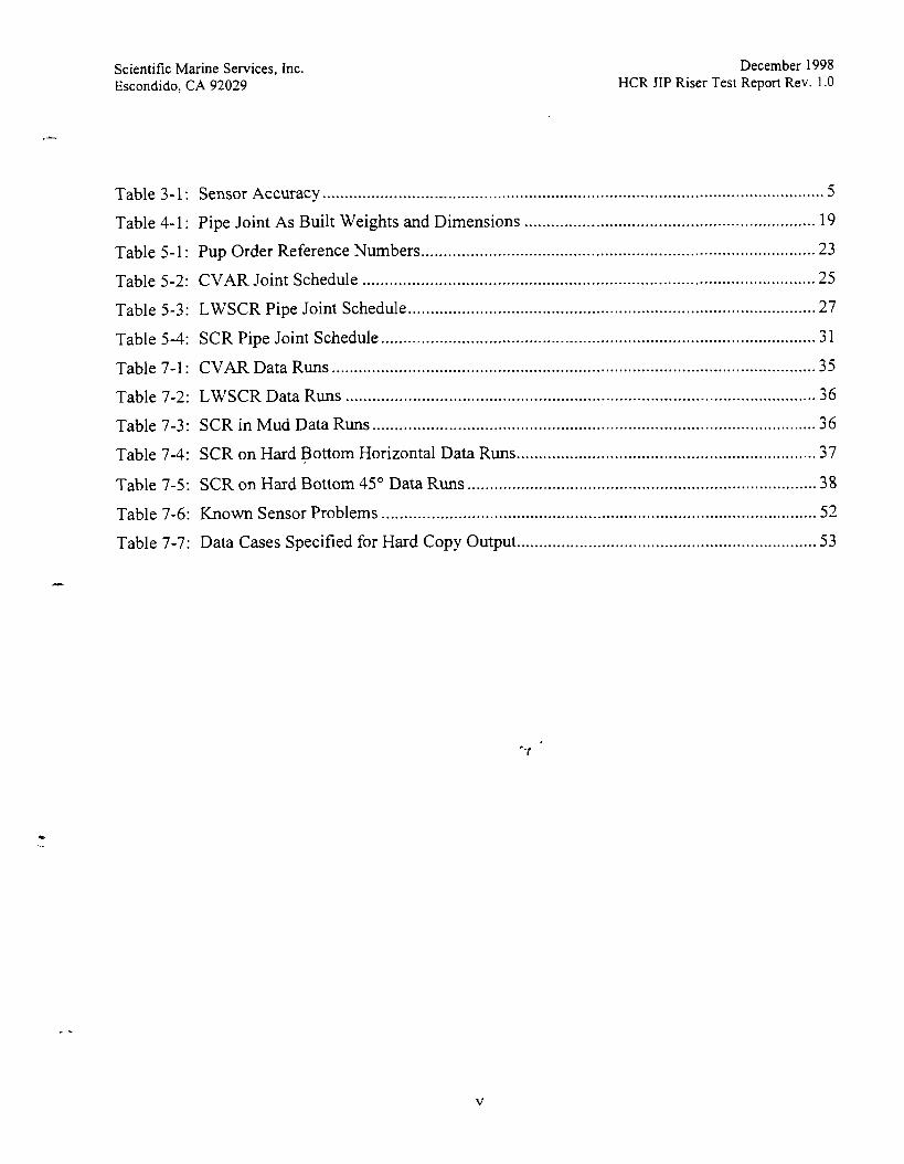
................................................................................................................ Table 3-1 : Sensor Accuracy 5
................................................................. Table 4-1 : Pipe Joint As Built Weights and Dimensions 19
........................................................................................ Table 5-1: Pup Order Reference Numbers 23
..................................................................................................... Table 5-2: CVAR Joint Schedule 25
........................................................................................... Table 5-3: LWSCR Pipe Joint Schedule 27
................................................................................................. Table 5-4: SCR Pipe Joint Schedule 31
............................................................................................................ Table 7-1 : CVAR Data Runs 35
......................................................................................................... Table 7-2: LWSCR Data Runs 36
................................................................................................... Table 7-3 : SCR in Mud Data Runs 36
................................................................... Table 7-4: SCR on Hard Bottom Horizontal Data Runs 37
.............................................................................. Table 7-5: SCR on Hard Bottom 45" Data Runs 38
................................................................................................. Table 7-6: Known Sensor Problems 52
................................................................... Table 7-7: Data Cases Specified for Hard Copy Output 53

Scientific Marine Services, Inc. Escondido, CA 92029
December 1998 HCR JIP Riser Test Report Rev. 1.0
I Executive Summary
In order to obtain a better understanding of the dynamic behavior of oil production risers and corroborate existing mathematical models, PMB Engineering contracted with Scientific Marine Services, Inc. (SMS) to design and construct three 'I, scale riser models and to provide force excitation, instrumentation, and data acquisition for the tests. The purpose of the instrumentation was to measure tension at the riser top and tension and bending moment at eight instrumented "pup" joints as well as barge 5 degree of freedom motions.
The tests were performed at the U. S. Navy Acoustic Research Detachment (ARD) facilities at Lake Pend Oreille, Bayview, Idaho. The test fixtures and equipment were installed aboard the ARD barge, "Karnloops" and operational support was provided by ARD personnel.
To accomplish these tasks, special instrumented pup joints were designed and manufactured by SMS. Each pup had strain gages to measure tension and bending strains as well as accelerometers to determine the pup orientation in space, allowing the bending moments to be translated from the pup coordinate system to the in plane and out of plane coordinate system. A load cell was used to measure top tension in the riser. A five degree of freedom motions package was used to measure barge motions during the tests. A high resolution GPS system was used to provide information for determining the positions of the riser anchor and riser top after the installation of each riser configuration. An ROV was used to assist with riser anchor placement, inspect the riser after installation, and act as a video platform during selected tests.
Three riser configurations were tested: the Combined Vertical Axis Riser (CVAR), Lazy Wave Steel Catenary Riser LWSCR), and the Steel Catenary Riser (SCR). The SCR was tested on the natural mud bottom of the lake and on an artificial hard bottom. Excitation was sinusoidal at constant amplitude for a range of periods. Three directions of excitation were tested: vertical, transverse horizontal, and 45" horizontal.
Test data was collected , reduced to engineering units,- and presented for further analysis by other parties. A sample of the reduced data is presented in this report and all the raw data is included on the accompanying CD-ROM.
These data provide information from large scale physical model tests to correlate mathematical models and provide a great deal of insight into the dynamic behavior of different riser configurations.

Scientific Marine Services, Inc. Escondido. CA 92029
December I998 HCR JIP Riser Test Report Rev. 1.0
2 Introduction
Large scale physical model tests were performed on three different riser configurations between 10 August and 2 October 1998 at Lake Pend Oreille, Bayview, Idaho. The tests were executed by Scientific Marine Services, Inc., under the direction of personnel from PMB Engineering. SMS designed, manufactured, and installed the forcing actuator, the riser model pipes, and specialized test instruments. Installation of the risers was accomplished in accordance with configurations provided by PMB personnel. The artificial hard bottom used during the SCR horizontal and 45" tests was conceived by SMS and designed and manufactured by PMB. Installation of the hard bottom was accomplished by ARD personnel supported by SMS under direct supervision from PMB senior engineers.
The purpose of these tests was to provide greater insight into the behavior of risers and corroborate mathematical models. Each riser model was excited through several vertical amplitudes and a range of frequencies. At each frequency, the steady state response was recorded for riser top tension, pup tension and bending at each pup, riser leaving angle, the vertical acceleration of the actuator mechanism, and the five degree of freedom motions of the Karnloops barge (yaw was not measured).
High accuracy GPS units were used to determine the location of the riser anchor during placement and the riser top while assembling the riser configuration. This allows precise determination of the location of the ends of each configuration so that the riser geometry may be determined.
+.". The results of these tests have provided a large amount of information which may be analyzed for comparison to various mathematical models of riser behavior.

Scientific Marine Services, Inc. Escondido, CA 92029
December 1998 HCR J1P Riser Test Report Rev. 1.0
3 Test Instrumentation
3.1 Data Acquisition system
3.1.1 Overview
The data acquisition system for this project consisted of two separate computers. One was used only to acquire, store and process Global Positioning System (GPS) information. The second was used for all other data collection and storage. Both computers are PC compatible with 100 MHz Pentium processors.
Signal conditioning and amplification for the analog data, actuator, and barge motions, was provided by a Scientific Marine Services proprietary IAF-01 electronics unit. SignaI conditioning for the riser data was accomplished by an EDC electronic unit located in each of the 2 foot long instrumented "pup" joints. Communications with the EDC units was via IEEE 485 serial link to the DAS. Data from all steady state tests was collected at 40 samples per second with 10 Hz filtering. Whack test data were collected at 80 samples per second with a 20Hz filter.
Raw data was stored on the hard drive of the data acquisition computer and archived daily onto a 2.3 gigabyte magneto opticaI disk.
3.1.2 Resolution, Accuracy, and Repeatability
System, accuracy, resolution, and repeatability are affected by all components of the system. Data being collected for the project was all analog and required conversion to digital format for computer interfacing and storage. Analog circuits, including the sensors, determine the accuracy and repeatability while the digital format sets the resolution of the data being collected. The analog values for gain and offset are determined during calibration. '7
Resolution of the data being collected is determined by the number of bits in the Analog to Digital converters used in the system. AID converter resolution is defined as:
Resolution = One LSB = VfsrIT.
Where:
LSB = least significant bit Vfsr = full scale input voltage range n = number of bits.
The IAF-01 electronics unit uses 12 bit AiD converters giving a resolution of Vfsrl4096. Data in the riser units, "PUPS" use 10 bit AID converters that are multiplied by 4 to give a pseudo 12 bit range while the resolution is Vfsrl1024. The Accuracy of the A to r converters is _+ 1/2 LSB.

Scientific Marine Services, Inc. Escondido, CA 92029
December 1998 HCR JIP Riser Test Report Rev. 1.0
Review of the processed data indicate PUP mean tension (static) values that are somewhat scattered. It was determined that the tensions not only had to be corrected for the effects of hoop stress and end cap pressure, but also cross talk from both X and Y bending moment into tension. Even after correcting for cross talk the tensions measurements are still somewhat scattered. Since the PUP tension measurements seem to be good at the surface, we have not been able to determine the cause of this scatter.
Regardless of the apparent scatter observed in the static data, the dynamic portion of the data will conform to the accuracy limits outlined in Section 3.1.2.
Table 3-1: Sensor Accuracy
1 TOP Tension Load Cell I k 5000 lb 1 + 0.05% FS 1 Sensor 1 Scale Maximum Value -
I 1 Actuator RollPitch 1 k 30" 1 + 2% FS
Accuracy
1 Actuator Accelerometer
Barge RollPitch
* 64.3 ft/s2
k 30" I
k 2% FS
Barge Accelerometers
+ 0.628 ft/s2 I
I I I
Pup Accelerometers
k 64.3 ft/s2
Pup Tension
A typical calibration plot for pup tension is given in Figure 3-1. All sensor calibration data are provided on the Raw Data CD-RO'M.
+ 0.628 ft/s2
+ 120 ft/s2
Pup Bending
+ 0.469 ft/s2
k 5000 lb k 1.13% FS
k 600 ft-lb + 2.3438 ft-lb

Scientific Marine Services, Inc. Escondido, CA 92029
December 1998 HCR JIP Riser Test Report Rev. I .O
I : - - . s i ? h r l o Y OF ?E.aTI?N BCTWECN "UP i00RDIN.rC
i STSTEM .ME RISER ?E'F4EYCC S I S : i *
~OLT=I*CES I sms
I 8-CYIHC PUP R D l l l T E 3 ! ,: :E ,::: iz ' -%?'- a - :-3:IWISE
,. !"a, rn - - F- ("0, .,r.wu ,- , r q - ,.,,., /I.
HCR 215E9 J P IOCA~ J i iP
C30ROINA-E S Y S T U "WLLll D l r L * r l s L I'C::'li3 - - r* i UI " r a- ,c .o * L L DI*c*l l iws asc :v .biles DO -, ,; 95 / 504 003-jZ -1- . - .3
Figure 3-2: Local Pup Coordinate System
3.2.2 Barge and Actuator Coordinate System
The barge and actuator also employ a right hand rule coordinate system as shown in Figure 3-3. This system is defined as follows:
+ X (surge) points forward in the line of actuation. + Y (sway) is normal to and points to port. + Z (heave) is normal to X and Y and points up.
- -
Figure 3-3: Barge Coordinate System

Scientific Marine Services, Inc. Escondido, CA 92029
December 1998 HCR JIP Riser Test Report Rev. 1.0
3.3.2 Pup Tension
Pup tension was measured using uniaxial strain gages. These gages were temperature compensated, using bridge completion strain gages mounted on an unstrained aluminum block. Poisson gages were not used, instead, the Poisson correction has been made to each pup tension based on the hoop stress at the theoretical nominal static pup depth for each riser configuration during the post test data reduction. Post test data reduction was also required to correct for the effects water pressure on the end caps and the cross talk effects of both X and Y bending moments. These corrections are handled by an additional set of derived channels and is discussed in the Data Reduction Section. Since the derived channels for tension used in the field tests did not contain these corrections, some negative tensions were displayed during the tests.
3.3.3 Bending
Bending stresses were measured using pairs of opposing uniaxial strain gages. These gages are self compensating and no correction for hoop stress or end pressure is required. Note that, as described in Section 3.2.1, the out of plane bending derived during the actual experiments was positive in the - Y direction. As requested during the tests, this has been modified to be positive in the +Y direction in the final data reduction using additional derived channels. The original channels used during the tests have been retained so that direct comparison with notes made in the field may be made if desired.
3.3.4 Accelerometers
The pup also contains four accelerometers, one orthogonal pair at each end of the pup. All accelerometers are oriented normal to the pup centerline. The accelerometers are used to provide twist information to allow the transformation of bending strains in the pup coordinate system to in and out of plane in the riser reference coordinate system. In addition, the accelerometers provide tilt information, but are not accurate w i h n 20" of the horizontal. '7
3.3.5 Temperature
A temperature sensor was included on one of the instrumentation boards to allow for temperature compensation of the accelerometers. It was determined during our calibration that the temperature correction was not necessary for this application and it was not used for the data reduction.
3.4 Actuator Instruments
3.4.1 Vertical Accelerometer
A vertical accelerometer was mounted on the actuator subcarriage. This accelerometer provided data on the actuator motion during operation. The location of the accelerometer is shown in Figure 3-5.

Scientific Marine Services. Inc. Escondido, CA 92029
December 1998 HCR JIP Riser Test Report Rev. 1.0
Prior to testing the CVAR and LWSCR riser configurations, the stinger was rotated minimize out of plane bending stresses in the pups, which necessitates correction of the leaving angle for rotation. The rotation is corrected for in the post test derived channel set. No correction was required for the SCR configuration.
3.4.3 Top Tension
The top tension of the riser was measured by a load cell mounted between the top of the stinger and the bottom of the actuator subcarriage assembly. The location of this load cell is shown in Figure 3-7.
Figure 3-7: Location of Top Tension Load Cell
3.5 Barge Motions '-. 3.5.1 5 Degree of Freedom Package
Barge motions were monitored during the tests using a 5 degree of freedom sensor package located on the actuator centerline under the reduction gear at the level of the actuator base. This package contained a triaxial accelerometer for surge, sway, and heave and a solid state roll - pitch gyro. Yaw was not measured. It should be noted that the sway accelerometer failed during the SCR tests. .
3.5.2 GPS
Two GPS antennas were mounted on the barge. One was located on the aft end of the A frame above the actuator and the other on the roof of the test shack. A third unit was used as a differential truthing station. This GPS was mounted on a tripod at Leiber, Point on a bluff overlooking the mooring site. Data from this GPS was transmitted to the

Scientific Marine Services, Inc. Escondido, CA 92029
December 1998 HCR JIP Riser Test Report Rev. 1.0
A special frame with adapters for the pups was fabricated for calibration of both tension and X-Y bending. A picture of the calibration frame is shown in Figure 3-8.
Figure 3-8: Pup Calibration Frame
The calibration data for each of the Pups is on the Raw Data CD-ROM.
3.6.1.1 Bending
'7 Certified weights were used to calibrate the X-Y bending. Twenty-one positions were used starting at zero and returning to zero. Pup data was collected for X and Y bending as well as Tension to check for cross talk. The resulting data collected was used for calibrating each of the corresponding channels in the pups.
3.6.1.2 Tension
The certified calibrated load cell, used for the actuator load, was used for the measuring standard. A turnbuckle was used to adjust the tension so that loads in excess of 4000 pounds could be achieved. For each pup, a total of 17 different tensions were used, starting at zero and returning to zero. Pup data was collected for Tension as well as X and Y bending to check for cross talk.

Scientific Marine Services, Inc. Escondido, CA 92029
December 1998 HCR JIP Riser Test Report Rev. 1.0
calibrated as a unit, using the SMS angular position test fixture described previouslq copy of the calibration plots is located on the Raw Data CD-ROM in files Bar-Pitch-Cal.xls and Bar-Roll-Cal.xls.
3.7 Current Measurement
During the field work, a surface current was observed. Measurements made using wood chips and a stop watch gave a surface velocity of approximately 15 cm/s (0.5 Ws). An ADCP was obtained and used to check for the presence of subsurface currents. An Acoustic Doppler Current Profiler sends out three acoustic pulses arranged at 120' intervals around the vertical - axis, with one beam pointing forward (in the +X barge coordinate system). The angle of the beams is about 30" to the vertical axis. The instrument works on the Doppler shift in the sound pulse as it reflects off particulate matter suspended in the water column. The ADCP was controlled by a laptop computer. Commands were passed to the ADCP and data received using an RS-232 serial link. Current profiles were displayed on the laptop screen.
The RD Instruments Work Horse ADCP that was used for these tests produced a 300 kHz pulse which results in a maximum profile depth of 100 m (328 feet). The water column is divided into depth "cells". The ADCP will fire a "ping" along each of the three beam axes and listen for a return at the appropriate time for each depth cell. The velocities from the three beams are averaged to produce a single velocity for each depth along the vertical axis of the instrument.
For these experiments, the ADCP was suspended on a rope cradle approximately 2 m below +'
water surface. This unit was operated on two occasions during the move fiom the CVAR ancL position to the LWSCR anchor position (when the barge was not moving) and on one occasion during the deployment of the SCR. Observation of the velocity profile on the computer screen showed that the maximum subsurface current was approximately 5 cm/s and that there was virtually no current indicated at depths greater than 30 m down to the instrument limit of 100 m. The conclusion from these measurements and additional visual observations was that these currents were wind generated and did not extend below 30 m.
3.8 ROV and Underwater Video -7
3.8.1 ROV
A Deep Ocean Engineering Phantom HDII remote operated vehicle was used to perform inspections and provide video of selected riser tests. The ROV was invaluable as an inspection tool, ensuring correct positioning and imbedment of the riser anchor as well as checlung the riser before beginning tests. A photograph of the ROV ready for deployment is shown in Figure 3-9.

Scientific Marine Services, Inc. Escondido, CA 92029
December 1998 HCR JIP Riser Test Report Rev. 1.0
is supplied with a 60 HP variable frequency controller which permits absorption of essentially full power over a speed range of 3 RPM to 20 RPM at the reduction gear output shaft (fly wheel). The controller was equipped with an oversized dynamic breaking resistor bank, which eliminated over-speeding during the part of the riser displacement cycle, which caused power to be put into the motor. The result was a truly constant speed apparatus with a low harmonic distortion of 0.2 %, based on power. By selecting the attitude of the actuator support structure the riser top could be excited with both vertical and horizontal displacements.
4.2 Tubing
The risers were constructed from 1.25" ID X 0.125" wall 606 1 -T65 1 1 extruded aluminum tube. Three lengths, 24'' 12'' 6' of riser pipe sections were constructed. The instrumented pups were also constructed of this material.
The material properties are as follows:
Material: Ultimate Strength:
Yield Strength: E:
Endurance Limit: O.D.: I.D.:
I : SM:
psi psi psi psi inches inches inA4 inA3
4.3 Joint Connections
The end flanges were machined from 6061-T6 a)uminum bar stock and welded to the tubing. The sections of riser were bolted together with 5/16-18 SAE grade 5 bolts torqued to 17 ft-lb dry using a "star pattern" torque sequencing order.
4.4 Welds and Quality Assurance
The API 1104 welding standard was used to check every weldrnent. The radiographic review was performed by Decisive Testing, Inc. and the welds judged on a passffail basis. Any weld which did not pass the standard was completely redone and then rechecked for compliance to the standard.
Flange face angular tolerance was specified to be less than 0.3" from normal to the tube longitudinal (z) axis. Each joint was checked on a passffail basis. Joints which did not pass were faced to 0".
The instrumented pups were pressure tested at 550 psi for 10 hours. Riser pipe segments were self-flooding.

Scientific Marine Services, Inc Escondido, CA 92029
December 1998 HCR JIP Riser Test Report Rev. 1 .O
Table 4-1: Pipe Joint As Built Weights and Dimensions - -

Scientific Marine Services, Inc. Escondido, CA 92029
December 1998 HCR JIP Riser Test Report Rev. 1.0
5 Test Configurations
5.1 General Assembly and Deployment Methods
All the riser configurations were assembled in using the same basic technique. Pipe handling was accomplished using an overhead trolley running along the I beams connecting the tops of the two A frames on the Kamloops barge. A line from one of the barge's 15,000 Ib winches was rove through a block on the trolley and was attached to an elevator which held the top end of each riser section while it was being raised. A certified digital scale was placed in the path between the block and the trolley attachment to provide a direct reading of the tension on the top of the riser during installation and removal. The procedure was as follows:
1 Bring the next riser section to be attached out of the pipe rack. If buoyancy modules are needed on this section, they must be put in place prior to placing the top end in the riser.
1 i If buoyancy modules are attached, it is important to leave off the top section, to allow room to install the connection bolts. The last buoyancy section is put in place after the bolts are tightened and the riser lifted from the slips in Step 7.
2 Raise the section to the vertical position and align the flange face with the section below.
3 Be sure that the alignment pin is facing forward and is aligned with the hole in the lower flange face.
4 If there is an electrical connection at this joint, it must be made here.
4.1 Check the connection for dirt, debris, or water. 4.2 Ensure that the power to the pups is off. 4.3 Make the connection, e n i ~ n g that it is tight. 4.4 Power up the system and verify that all pups below are reading.
5 The riser section was attached to the section below by 6 bolts. Insert the bolts and tighten them to the specified torque using a star pattern.
6 Raise the assembled unit to allow the pipe slips to disengage.
7 Remove the pipe slips and lower the riser until about two feet of pipe remains above the level of the slips. If the electronics are connected, monitor the pup bending moments during the lowering process.
8 Put the slips back around the pipe and lower the riser until the slips engage.
9 If there is an electrical connection at this joint, it must be broken here.

Scientific Marine Services, Inc. Escondido, CA 92029
December 1998 HCR JIP Riser Test Report Rev. 1.0
5.2 Configuration Descriptions
Three different riser configurations were tested. These are the CVAR, LWSCR, and SCR. The CVAR and LWSCR have buoyancy modules on some joints, the SCR had no buoyancy modules, but was tested on both the natural mud bottom of the lake and an artificial hard bottom deployed for this purpose. The details of the risers are given in the following sections.
In each riser configuration, pups were always numbered from 1 to 8, starting at the end nearest the actuator. It is important to know which physical calibration file corresponds to which pup. Table 5-1 provides the pup order reference data:
Table 5-1: Pup Order Reference Numbers
5.2.1 CVAR
Order No. r
1
The CVAR configuration was deployed in accordance with the layout is given in Figures 5-1 and 5-2. The pipe joint installation schedule is given in Table 5-2.
CVAR
2
LWSCR
2
SCR
10

Scientific Marine Services, Inc. Escondido, CA 92029
December 1998 HCR JIP Riser Test Repon Rev. 1.0
Table 5-2: CVAR Joint Schedule
Scientific Marine Services, Inc. Escondido, CA 92029
December 1998 HCR JIP h s e r Test Report Rev. 1.0
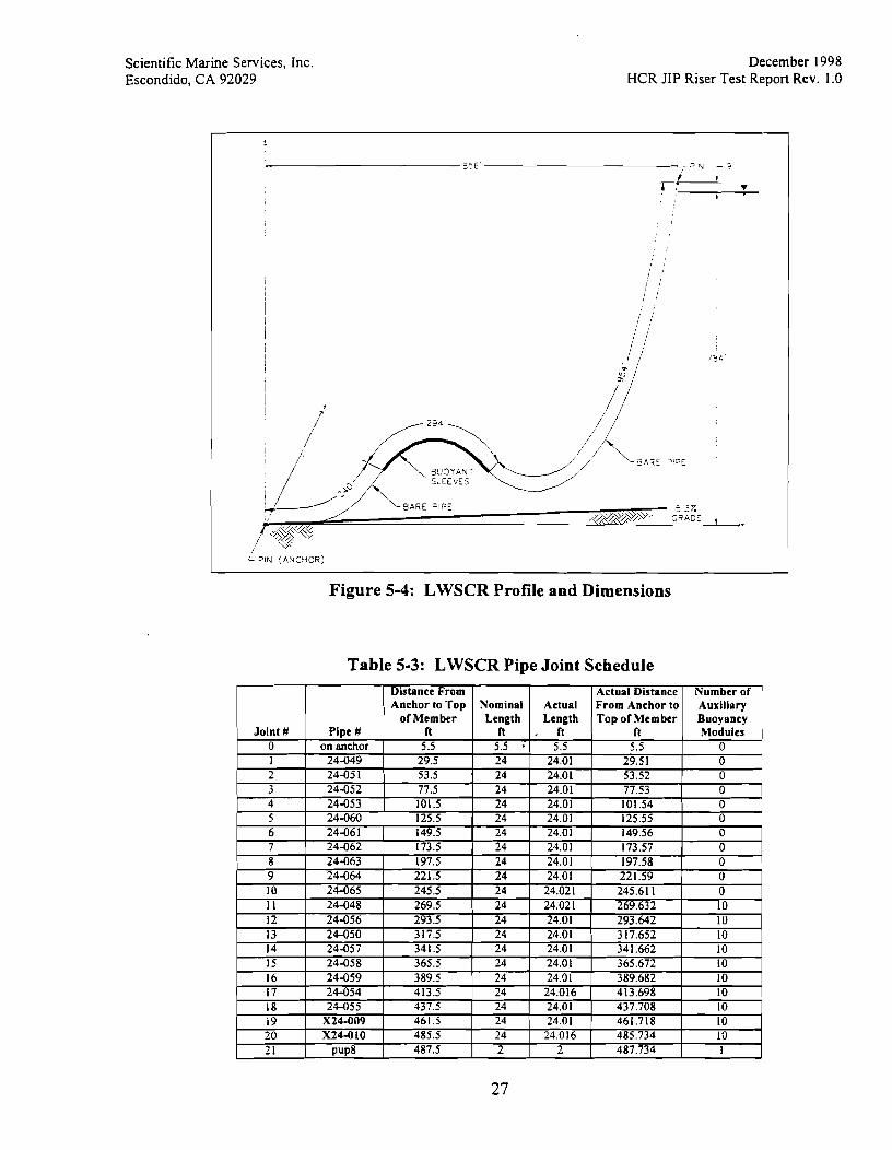
Figure 5-4: LWSCR Profile and Dimensions
Table 5-3: LWSCR Pipe Joint Schedule

Scientific Marine Services, Inc. Escondido, CA 92029
December 1998 HCR JIP Riser Test Report Rev. 1.0
installation, due to an error, instrumented pups numbers 5 and 6 (also known as pup physical reference numbers 5 and 6) were installed upside down. This will result in the sign of the Y bending and Y axis accelerations being reversed from the standard sign convention in the raw data. This problem was addressed in the SCR2MAT and SCR2CSV programs, so that after running either program, the derived channels for the final corrected out of plane bending for these pups have the correct sign, consistent with the standard reference system and all the other pups. It should be noted that the raw data is not altered in any way, therefore people who wish to manipulate these data themselves should be aware that the signs for the raw Y axis bending and accelerometers are reversed. All other pups were installed in the correct orientation.
Also for this configuration, one pup (pup order number 1, physical reference number 10) was installed near the top attachment. In order to maintain the total number of eight instruments, one was removed from the sag bend region, therefore for the SCR, there are 7 pups in the sag bend region and 1 pup close to the top attachment point. When pup 10 was installed in the line, the calibration factor was altered to increase the sensitivity as requested,for all other pups after the CVAR tests. Unfortunately, the Command Data Word (CDW: the programming command which sets the properties of the AID converter on each pup) was never altered in the pup, so the electronic gain remained as originally set. This problem has been corrected in the post test reduction by correctly matching the calibration factor to the electrical gain. The result is that the tension readings for this pup have half the resolution of the other 7 pups in the string. Since this pup was located near the top where the tension readings are the highest, this should not be a significant problem.
Pipe joints 9 through 28 had fairing cones bolted on at the flanges to prevent the flange from becoming stuck on the hinged joints of the hard bottom. The cones were not removed during the SCR tests in mud. A photograph of a typical cone installation is given in Figure 5.8.
Figure 5-5: Pup Location Drawing for SCR

Scientific Marine Services, Inc. Escondido, CA 92029
December 1998 HCR JIP Riser Test Report Rev. 1.0
Table 5-4: SCR Pipe Joint Schedule

Scientific Marine Services, Inc. Escondido, CA 92029
December 1 998 HCR JIP Riser Test Report Rev. 1.0
6.3 Data Collection
While the actuator control was operated by an SMS engineer, the data collection was initiated and terminated by a PMB engineer. During some runs, data was collected during ramp up or ramp down as well as during the steady state portion of the tests. The determination of steady state was made by the engineer operating the DAS based on his observations of the real time data displays.
During the CVAR and LWSCR tests, kinematic GPS data was collected. This collection was initiated by an SMS engineer prior to the start of the actuator. The purpose of the GPS data was to provide a record of barge movement during the tests. However, due to the relatively high horizon masking due to the surrounding mountains, the GPS conditions were not good enough to produce centimeter level accuracy track plots which are required for precise motion tracking. The GPS data were good enough to produce sub-meter level accuracy positions which were used to determine the locations of the riser anchor and top. By direction from PMB personnel, kinematic GPS data was not taken during the SCR tests. GPS data converted to latitude, longitude, and elevations for the data that was taken are included on the Raw Data CD-ROM.
6.4 ROV Operation
All ROV operations were conducted by SMS personnel with some umbilical tending assistance from ARD personnel.
At depths greater than about 100 feet, visibility through the ROV video camera was, at best, on the order of 15 - 20 feet. The Phantom HD I1 vehicle leased for this project was not equipped with a sonar, so if the ROV pilot lost sight of the riser and became disoriented, the standard procedure was to fly back along the umbilical to the surface, re-acquire the riser visually, and then return to the current task. This procedure minimized the chance of tangling the umbilical around the riser or any of the mooring lines, which would cause problems retrieving the ROV.
The ROV was deployed prior to each riser anchor imbedment to inspect the riser, anchor, and the bottom where penetration would take place tgverify that it was free from obstructions. The ROV was also used to verify proper deployment of the hard bottom and assist with its placement on the mud. Typically, a video tape record was made of each ROV deployment from the time the ROV left the surface until the start of the return trip to the surface. The original video tapes have been retained for the record by PMB.
Prior to the beginning of the large amplitude test sequence for each riser configuration, the ROV was deployed and flown to a location on the riser specified by PMB personnel, where the motion was expected to be interesting. For the CVAR and LWSCR this was in mid-water at the region of curvature. For the SCR, the location was on the bottom near the touch down point.


Scientific Marine Services, Inc. Escondido, CA 92029
December 1998 HCR JIP Riser Test Report Rev. 1.0
Table 7-4: SCR on Hard Bottom Horizontal Data Runs
37
Scientific Marine Services, Inc. Escondido, CA 92029
December 1998 HCR JIP Riser Test Report Rev. 1.0
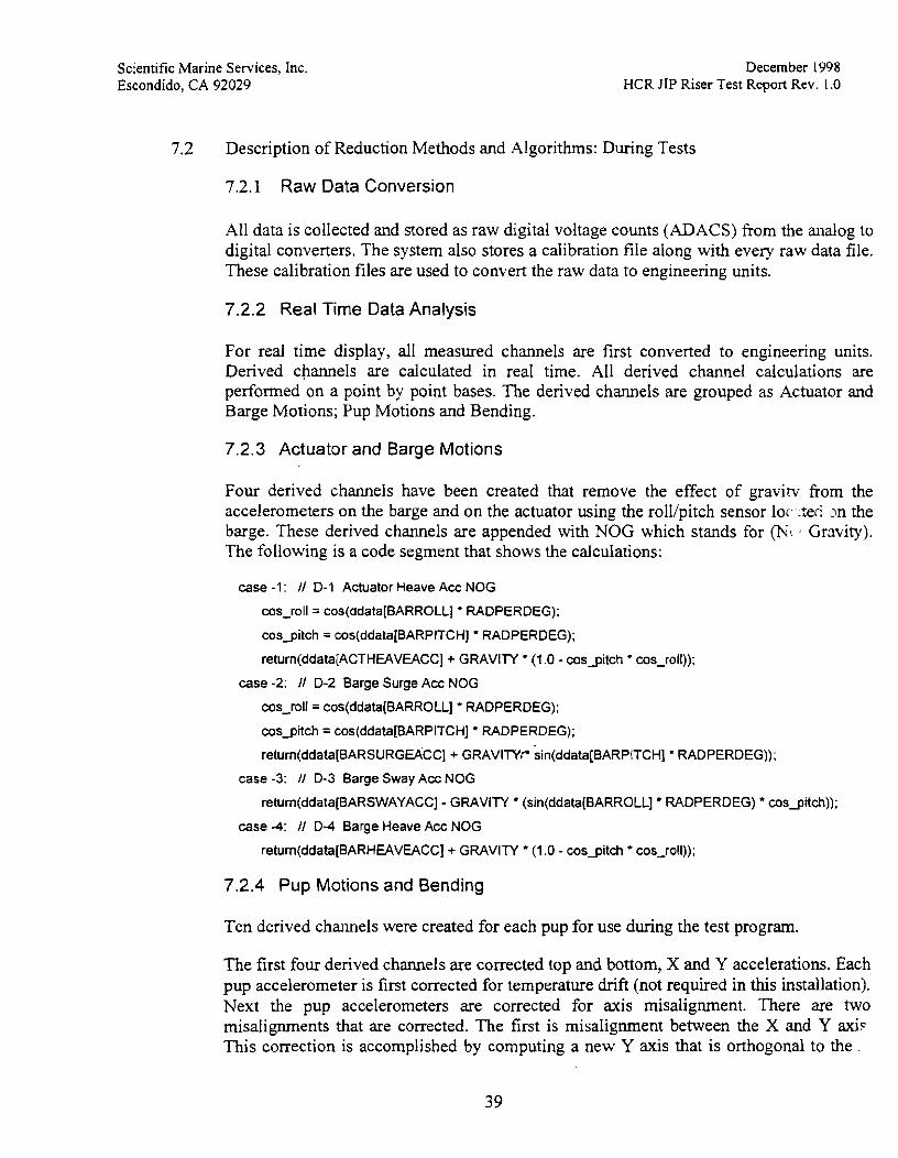
Description of Reduction Methods and Algorithms: During Tests
7.2.1 Raw Data Conversion
All data is collected and stored as raw digital voltage counts (ADACS) fiom the analog to digital converters. The system also stores a calibration file along with every raw data file. These calibration files are used to convert the raw data to engineering units.
7.2.2 Real Time Data Analysis
For real time display, all measured channels are first converted to engineering units. Derived channels are calculated in real time. All derived channel calculations are performed on a point by point bases. The derived channels are grouped as Actuator and Barge Motions; Pup Motions and Bending.
7.2.3 Actuator and Barge Motions
Four derived channels have been created that remove the effect of gravitv fiom the accelerometers on the barge and on the actuator using the roll/pitch sensor 1oc::ted on the barge. These derived channels are appended with NOG which stands for (h;! a Gravity). The following is a code segment that shows the calculations:
case -1 : I1 D-I Actuator Heave Acc NOG
cos-roll= cos(ddata[BARROLL] RADPERDEG);
cosgitch = cos(ddata[BARPITCH] * RADPERDEG);
return(ddata[ACTHEAVEACC] + GRAVITY (1.0 - cosgitch cos-roll));
case -2: I1 D-2 Barge Surge Acc NOG
cos-roll= cos(ddata[BARROLL] RADPERDEG);
cosgitch = cos(ddata[BARPITCH] RADPERDEG);
return(ddata(BARSURGEACC1 + GRAVITY*& BARPITCHI PIT PIT CHI RADPERDEG));
case -3: I1 D-3 Barge Sway Ace NOG
return(ddata[BARSWAYACC] - GRAVITY (sin(ddata[BARROLL] RADPERDEG) cosgitch));
case -4: I1 D-4 Barge Heave Acc NOG
return(ddata[BARHEAVEACC] + GRAVITY (1.0 - cosgitch cos-roll));
7.2.4 Pup Motions and Bending
Ten derived channels were created for each pup for use during the test program.
The first four derived channels are corrected top and bottom, X and Y accelerations. Each pup accelerometer is first corrected for temperature dnft (not required in this installation). Next the pup accelerometers are corrected for axis misalignment. There are two misalignments that are corrected. The first is misalignment between the X and Y axi? This correction is accomplished by computing a new Y axis that is orthogonal to the

Scientific Marine Services, Inc. Escondido, CA 92029
December 1998 HCR JIP Riser Test Report Rev. 1.0
// average Y acceleration
p l y = (plty + p l by) / 2.0;
// filter Y acceleration
p l y = FILTER-nextsample(p1 y, 8plyfilt);
return(p1 y);
case -1 0: // D-10 PLlP 1 Static X Acc
// average X acceleration
p l x = ( p l b + plbx) / 2.0;
// filter X acceleration
p l x = FILTER-nextsample(plx, &pl xfilt);
return(p1 x);
The next derived channel calculates the pup rotation based on the static X and Y accelerations calculated above. This quasi static rotation was used for rotations displayed during the testing, however the mean rotation value determined fiom the 5 minute statistics file prior to the start of each test was used for the final post test processing in cases above -85 The following is a code segment that shows the calculations used during the field work:
case -1 1 : // D-1 1 PUP 1 Rotation
if (ply == 0.0 && p l x == 0.0)
p l rot = 0.0;
else
p i rot = -atan2(pl y, pix);
p i rotdeg = DEGPERRAD (pi rot -1); // changed sign of p i rot to + so rotation is correct
if (p i rotdeg c 0.0)
p l rotdeg += 360.0;
return(p1 rotdeg); '7
The next derived channel calculates the pup tilt. The static X and Y accelerations calculated above are using for this calculation. Please Note: this derived channel is not accurate when the pup is within 20 degrees of the horizontal plane. The following is a code segment that shows the calculations:
case -12: // D-12 PUP 1 Tilt lnplane
temp = sqrt(p1 y p i y + p i x pix) / GRAVITY;
if (temp > 1 .O)
temp = 1 .O;
if (temp c -1 .O)
temp = -1 .O;
return(DEGPERRAD ' acos(temp));

Scientific Marine Services, Inc Escondido, CA 92029
December 1998 HCR JIP Riser Test Report Rev. 1.0
This resulted in the creation of 6 derived channels for each pup. The equations (shc for Pup 1) are as follows:
case -85: /I D-85 Pipe Pitch COR - rotate pitch & roll using input pipe top rotation
return(ddata[PIPEPITCH] ' cos(piperot ' RADPERDEG) - ddata[PIPEROLL] sin(piperot ' RADPERDEG));
case -86: /I D-86 Pipe Roll COR - rotate pitch & roll using input pipe top rotation
retum(ddata[PIPEROLL] ' cos(piperot ' RADPERDEG) + ddata[PIPEPITCH] sin(piperot ' RADPERDEG));
case -87: I/ D-87 PUP 1 Static Rotation
return(p1 rotcst);
case -88: /I D-88 PUP 1 Static Tilt lnplane
return(p1 tiltcst);
case -89: /I D-89 PUP 1 Bend lnplane COR - rotate bending using input rotation
return(ddata[PUPlBENDX] ' cos(-plrotcst RADPERDEG) - ddata[PUPl BENDY] ' sin(-plrotcst RADPERDEG));
case -90: /I D-90 PUP 1 Bend Outplane COR - rotate bending using input rotation
return-l'(ddata[PUPlBENDY] cos(-pl rotcst ' RADPERDEG) + ddata[PUPl BENDX] ' sin(- p i rotcst ' RADPERDEG));
/I Added -1 ' to change the sign for "Bend Outplane COR" 23 Nov. 98 GCF all pups N
7.3.2 Correction of Measured Tension for Hoop Stress, End Pressure and Cro Talk
The tension data measured by the pups was affected by the water pressure at the submerged depth of each pup. This pressure caused the air filled pups to compress creating a false tension reading, due to the z axis component of hoop stress, and a real compression due to end cap pressure. These forces were calculated based on the theoretical mean depth of the individual pups in each riser configuration, which was provided by PMB. The correction was reduced to a single value function based on depth and a subroutine was written to provide the corrected tension due to pressure for each pup. The water pressure correction f ic t ion is as follows:
Function description: Corrects for water pressure. This includes correction for end pressure and hoop stress.
Input: tension in Ibs.
depth in feet
Output: corrected tension in Ibs.
double correcttension(doub1e tension, double depth)
{
retum(tension + depth ' 0.23382);

Scientific Marine Services, Inc. Escondido, CA 92029
December 1998 HCR JIP Riser Test Report Rev. 1.0
7.3.4 Reduced Constant Frequency Statistics
The steady state data from all test runs was reduced and converted to engineering units using the appropriate RAW2MAT conversion program. The data were then processed using proprietary Matlab routines to produce the required statistics. Two sets of output files have been generated for each tested riser configuration: one for the barge motions and a second for the tension and bending information.
The barge motion files contain the following information for each period and amplitude:
1. Channel Name
2. Units (Physical Units)
3. Minimum
4. Maximum
5. Mean
6. Standard Deviation
7. Significant Amplitude
8. Period (Mean Zero Up-crossing Period)
The data presented is:
1. Barge Roll
2. Barge Pitch
3. Barge Surge Acceleration NOG
4. Barge Sway Acceleration NOG
5. Barge Heave Acceleratiqn NOG r
These data are not evaluated as part of this report.
The tension and bending moment files contain the following information for each period and amplitude:
1. ChannelName
2. Units (Physical Units)
3. Minimum
4. Maximum
5. Mean
6. Average Peak to Peak (Time Domain)
7. Ratio Peak to Peak (Time Domain)

Scientific Marine Services, Inc. Escondido, CA 92029
December 1998 HCR JIP Riser Test Repon Rev. 1.0
displacement, the RAO calculated from the peak of the FFT closest to the excita frequency1 the peak of the actuator displacement FFT.
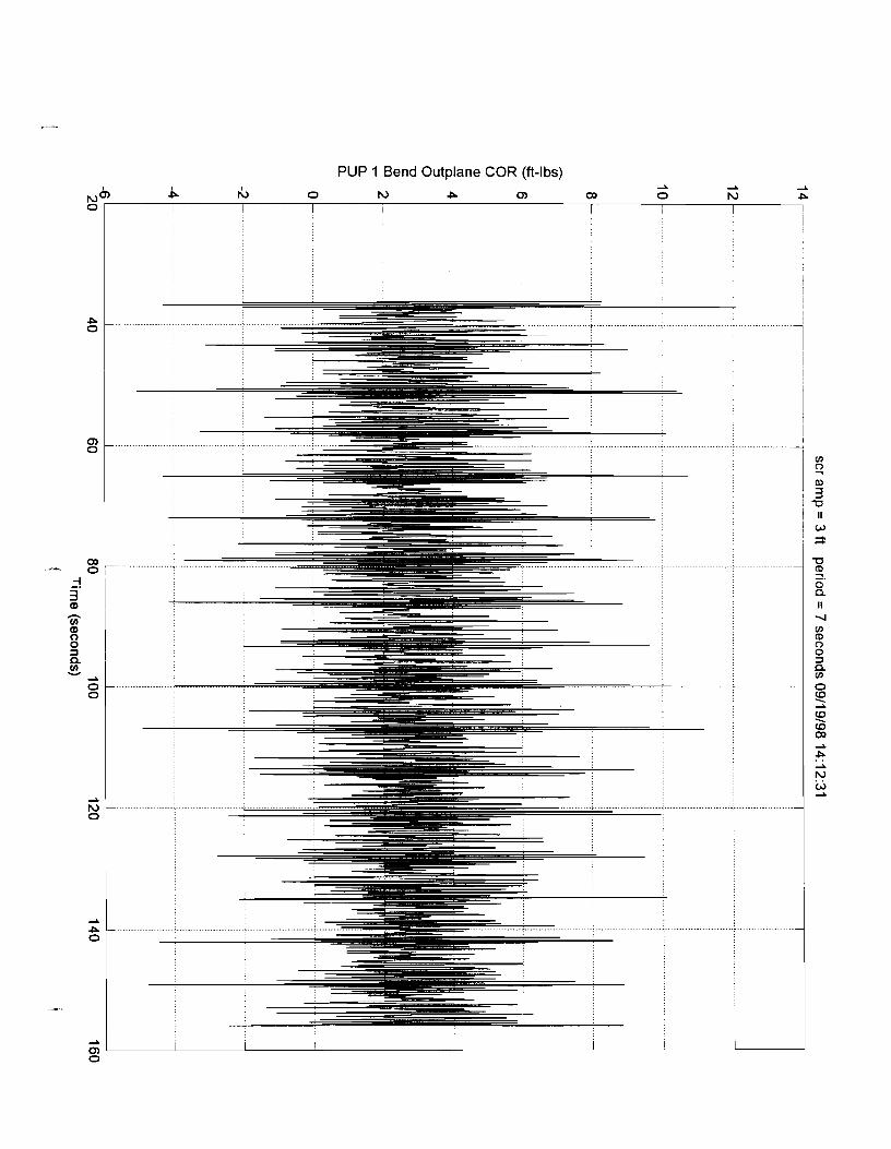
SMS decided not to filter the data beyond the filtering provided by the analog anti- aliasing filters(l0 Hz cutoff). Consequently, even the tension and in-plane responses contain significant harmonic content different from the fundamental. As a result, the Average Peak to Peak listed in the statistics tables often does not reflect the peak to peak of the fundamental response. The zero crossing routine was confused by the higher harmonics. Consequently, the "Ratio p-p" is also of limited value. However, the RAO has been calculated from the response at the fundamental excitation frequency and is a valid number.
The peak to peak values listed in the statistical summaries should be used only for the cases where the "Ratio P-P" is in close agreement with "RAO".
Barge motion files are stored on the Processed Data CD-ROM and labeled by configuration (i.e. "CVAR Barge Motions.CSV")
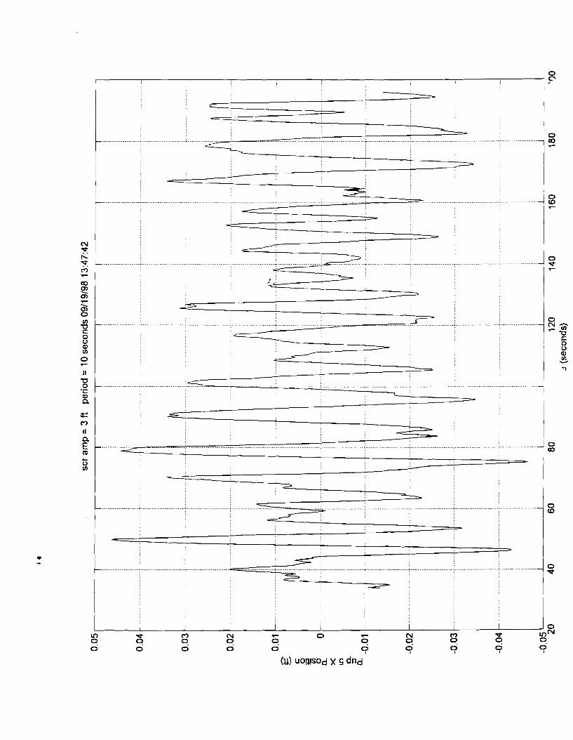
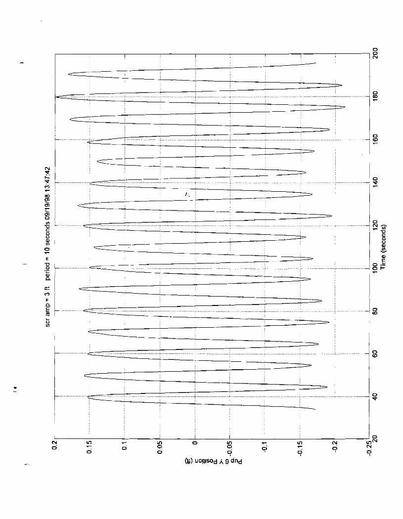
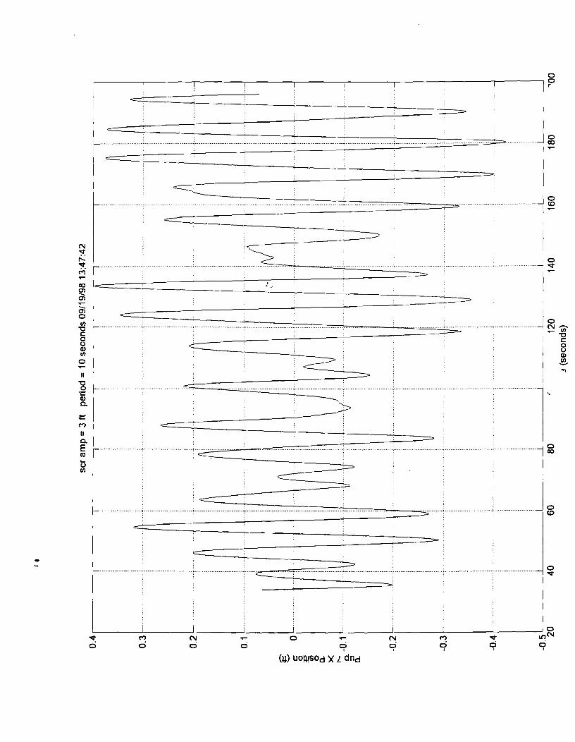
7.3.5 Pup Motion Analysis
The X and Y accelerometer data from the pups was double integrated to determine the motion of each pup. To perform this analysis, a Matlab routine was prepared which corrected the accelerometers for the effects of gravity due to tilt and roll, transform; them to the mid-point of the pup and then into "X Acc NOG" and "Y Acc NO accelerations. These accelerations were then double integrated to produce "X Positions" "(In-Plane values) and "Y Positions" (Out-of-Plane values). Both corrected top and bottom accelerations and the processed channels are presented.
The following equations were taken from the Matlab program used to perform this analysis for each pup:
First: calculate dynamic angular accglerations
% top-bot difference in X acceleration /distance to give dynamic angular pitch acceleration
dXacc = ((data(3+Ci-l)*4.:)data(5+(j-l)*4,:))/dist)*degperrad; % pitch
avgXacc = (data(3+(j-1)*4,:)+data(5+(i-l)*4,:))/2;
avgYacc = (data(2+(j-1)*4,:)+data(4+(j-l)*4,:))12;
addchan(dXacc,rPup ' int2str(j) ' Arlgular Pitch Acc'], 'degIs2');
addchan(avgXacc,rPup ' int2strO) ' Avg X Acc'], 'Ws2');
addchan(avgYacc,rPup ' int2str(j) ' Avg Y Acc'], 'Ws2');
Second: double integrate to get dynamic angles using Matlab and SMS proprietary routines returning int2str('j).
Third: add static angles determined from 5 minute statistics files back in for pit only:

Scientific Marine Services, Inc. Escondido, CA 92029
10. Pup 3 Top X Acc COR
11. Pup 3 Bot Y Acc COR
12. Pup 3 Bot X Acc COR
13. P u p 4 T o p Y Acc COR
14. Pup 4 Top X Acc COR
15. Pup 4 Bot Y Acc COR
16. Pup 4 Bot X Acc COR
17. Pup 5 Top Y Acc COR
18. Pup 5 Top X Acc COR
19. Pup 5 Bot Y Acc COR
20. Pup 5 Bot X Acc COR
' 21. Pup 6 Top Y Acc COR
22. Pup 6 Top X Acc COR
23. Pup 6 Bot Y Acc COR
24. Pup 6 Bot X Acc COR
25. Pup 7 Top Y Acc COR
26. Pup 7 Top X Acc COR
27. Pup 7 Bot Y Acc COR
28. Pup 7 Bot X Acc COR
29. Pup 8 Top Y Acc COR
30. Pup 8 Top X Acc COR
31.Pup8BotYAccCOR '7
32. Pup 8 Bot X Acc COR
33. Displacement
34. Pup 1 X Acc NOG
35. Pup 1 Y Acc NOG
36. Pup 1 X Position
37. Pup 1 Y Position
38. Pup 1 X Acc NOG
39. Pup 1 Y Acc NOG
40. Pup 1 X Position
41. Pup 2 Y Position
December 1998 HCR JIP Riser Test Report Rev. I .O
Scientific Marine Services, Inc. Escondido, CA 92029
December 1998 HCR JIP Riser Test Report Rev. 1.0
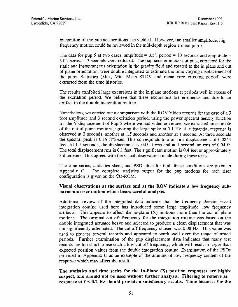
integration of the pup accelerations has yielded. However, the smaller amplitude, hig. frequency motion could be reviewed in the mid-depth region around pup 5.
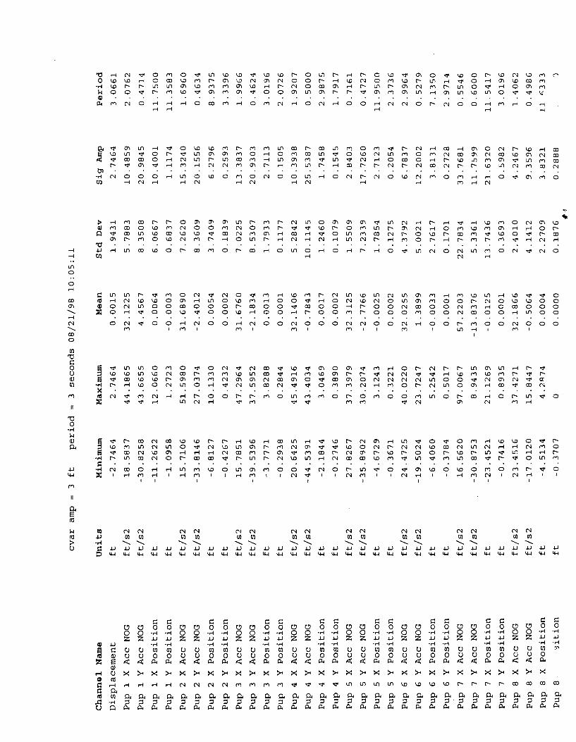
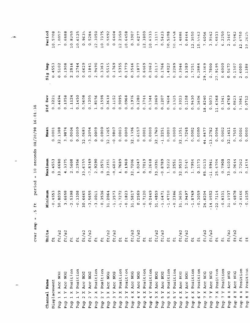
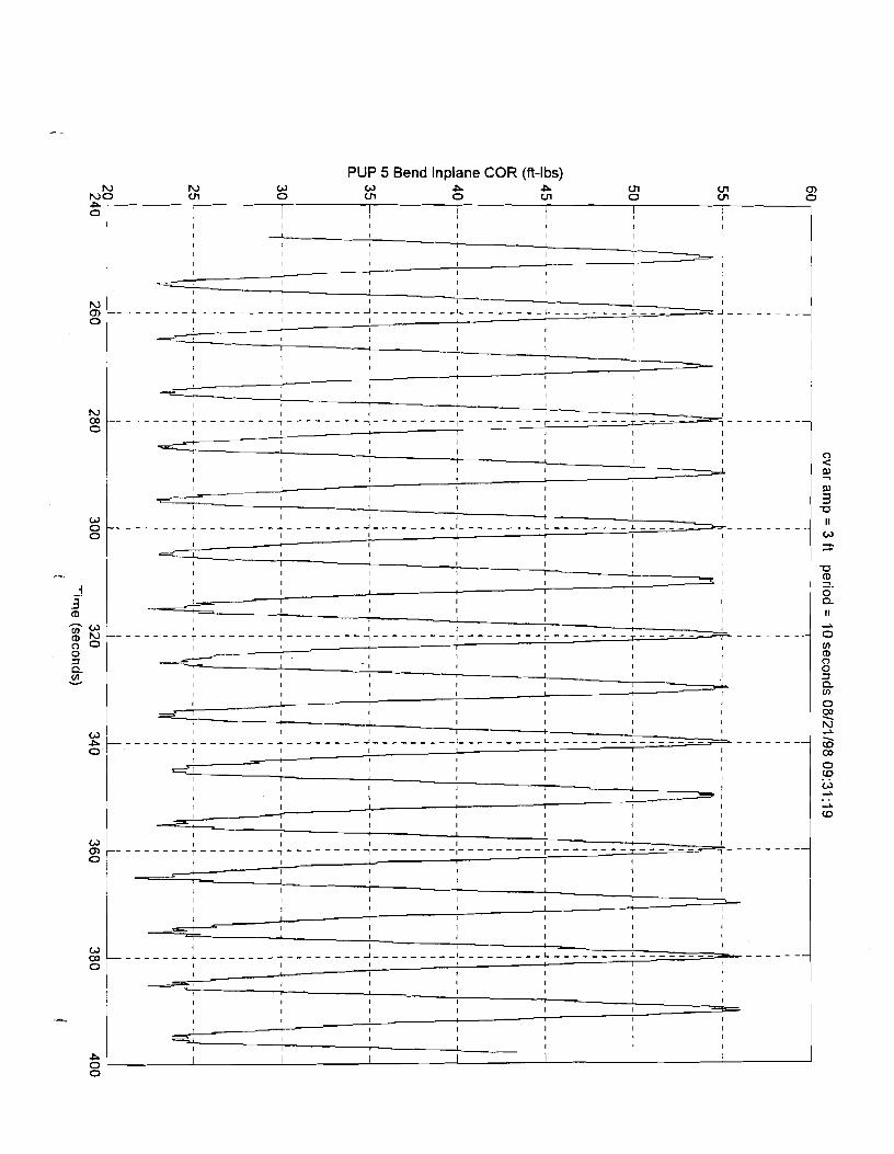
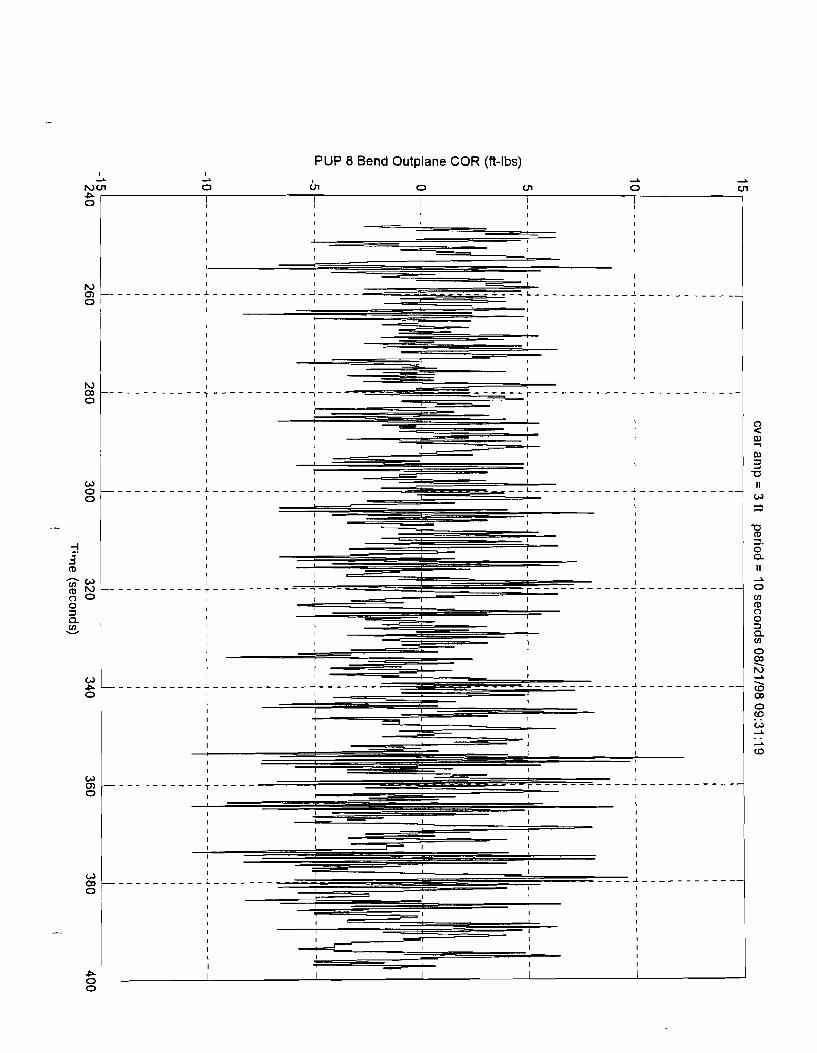
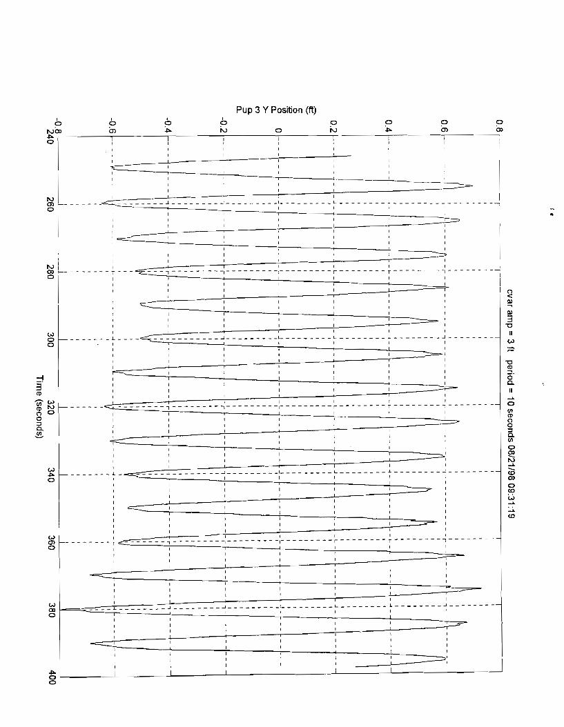
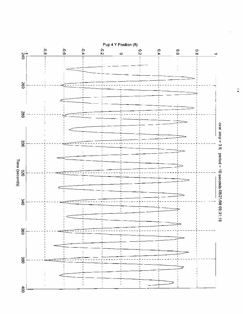
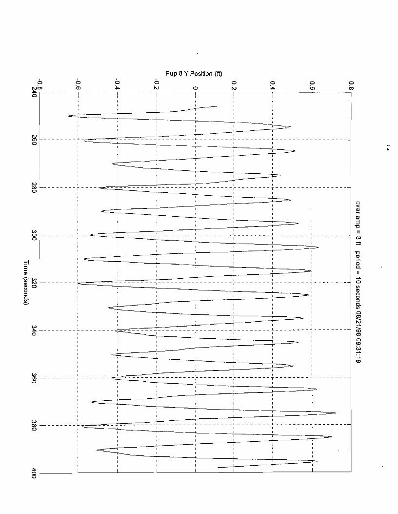
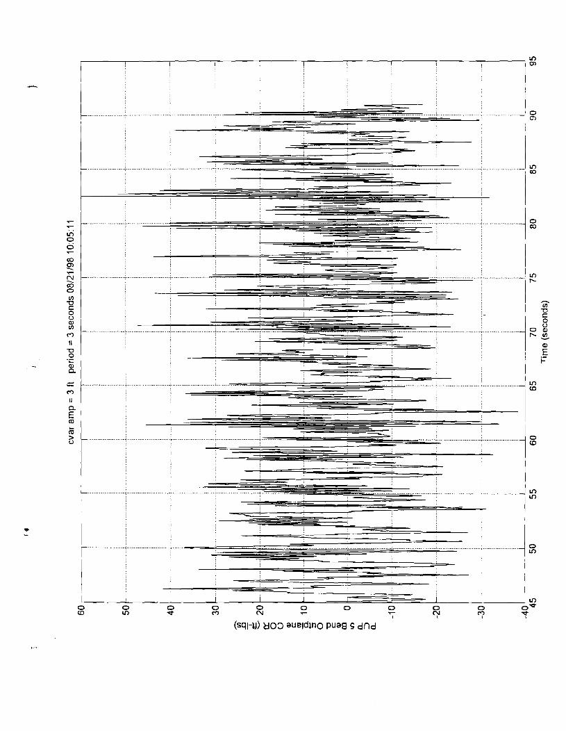
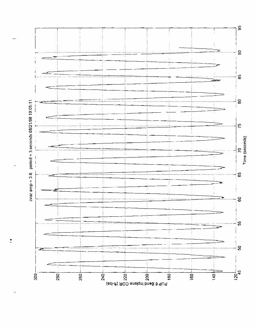
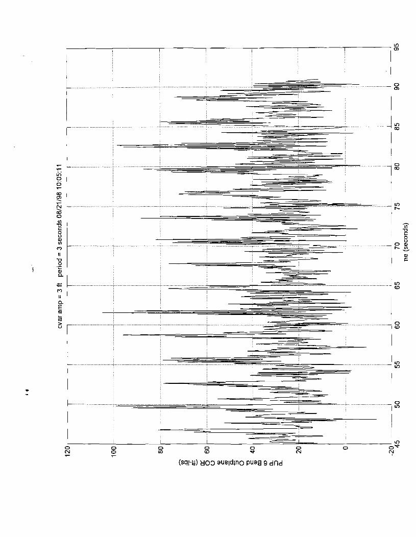
The data for pup 5 at two cases, amplitude = 0.5', period = 10 seconds and amplitude = 3.0': period = 3 seconds were reduced. The pup accelerometer out puts, corrected for the static and instantaneous orientation in the gravity field and rotated to the in plane and out of plane orientation, were double integrated to estimate the time varying displacement of the pups. Statistics (Max, Min, Mean STDV and mean zero crossing period) were extracted from the time histories.
The results exhibited large excursions in the in plane motions at periods well in excess of the excitation period. We believe that these excursions are erroneous and due to an artifact in the double integration routine.
Nonetheless, we carried out a comparison with the ROV Video records for the case of a 3 foot amplitude and 3 second excitation period. using the power spectral density function for the Y displacement of Pup 5 where we had video coverage, we extracted an estimate of the out of plane motions, ignoring the large spike at 0.1 Hz. A substantial response is observed at 3 seconds, another at 1.5 seconds and another at 1 second. At three seconds the spectral peak is 0.19 ftA2-sec. This corresponds to a an rms displacement of 0.0844 feet. At 1.5 seconds, the displacement is .045 ft rms and at 1 second, an rms of 0.04 ft. The total displacement rms is 0.1 feet. The significant motion is 0.4 feet or approximately 3 diameters. This agrees with the visual observations made during these tests.
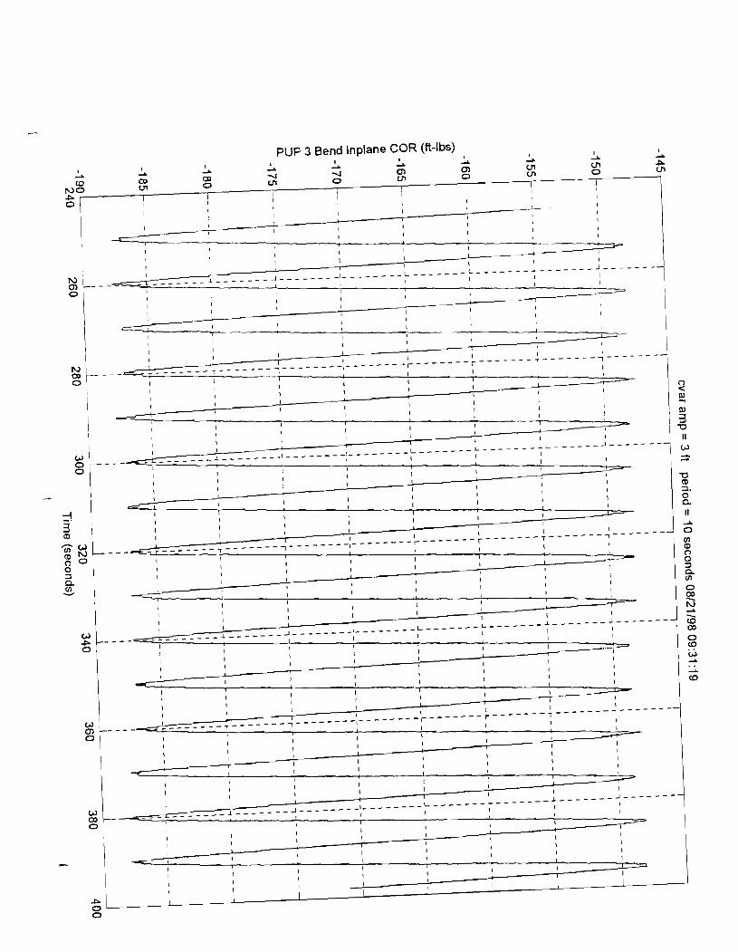
The time series, statistics sheet, and PSD plots for both these conditions are given in Appendix C. The complete statistics output for the pup motions for sach riser configuration is given on the CD-ROM.
Visual observations at the surface and at the ROV indicate a low frequency sub- harmonic riser motion which bears careful analysis.
Additional review of the integrated data indicate that the frequency domain based integration .routine used here has introduced some large amplitude, low frequency artifacts. This appears to affect the in-plane (X) motions more than the out of plane motions. The original cut off frequency for the integration routine was based on the double integrated actuator heave and selected to produce a clean displacement that was not significantly attenuated. The cut off frequency chosen was 0.08 Hz. This value was used to process several records and appeared to work well over the range of tested periods. Further examination of the pup displacement data indicates that many test records are too short to use such a low cut off frequency, which will result in larger than expected position values from the double integration routine. Examination of the PSDs provided in Appendix C as an example of the amount of low frequency content of the response which may affect the result.
The statistics and time series for the In-Plane (X) position responses are highlv suspect, and should not be used without further analysis. Filtering to remove ar response at f < 0.2 Hz should provide a satisfactory results. Time histories for the
5 1

Scientific Marine Services, Inc. Escondido, CA 92029
December 1998 HCR JIP Riser Test Report Rev. 1.0
I I (s) I (ft) I Orientation I
Table 7-7: Data Cases Specified for Hard Copy Output
Case
CVAR 1
CVAR 2
5 1 3.0 I Vertical 1
Amplitude Period
SCR 1
SCR 2
Amplitude
10
3
10
7
SCR 4
3.0
3.0
L W I
7.3.8 Description of File Formats
Vertical
Vertical
3 .O
3 .O
3
LW2
7.3.8.1 Calibration Files
Vertical
Vertical
10
The calibration files are in a text format which may be read by any text editor, such as Notepad. These files contain all the information necessary to convert the associated raw data file into engineering units. An example of a calibration file is given in Appendix E. Calibration files are recorded for each raw data record to ensure that the proper calibration values are available for later data reduction. All calibration files are provided with their matching raw data on the CD-ROMs.
3 $0
3.5
7.3.8.2 Constants Files '7
The constants files are used to providing constant values for use in the data reduction equations that a user may wish to alter. These include information such as static rotation offset and tilt and pup depth. These files are also in a text format. An example of a constants file is given in Appendix F. All constants files are provided with their matching raw data on the CD-ROMs.
Vertical
4.0
7.3.8.3 Data File
Vertical
4.0
Data files are recorded in a binary format to minimize storage requirements. These binary files may be unpacked into either a Matlab format or into an ASCII CSV format file by using the appropriate routine. All raw data files are included on the Raw Data CD-ROM.
Vertical

Scientific Marine Services, Inc. Escondido, CA 92029
December 1998 HCR JIP Riser Test Report Rev. 1.0
8 Commentary on System Performance
8.1 Riser Handling Equipment
In general, the riser handling equipment functioned very well. The slips, elevator, and trolley system all worked as designed.
8.2 Actuator
The actuator performed reasonably well, with total harmonic distortion based on power of 0.2%. Due to design changes made to increase the load capacity and stiffness of the subcarriage which were not reflected in the outer frame, the clearance for the 4 foot stroke is very small. The subcarriage and frame actually came in contact once during the LWSCR tests, resulting in some fractured welds and down time to repair the damage.
Additionally, the rigid shaft connections caused some alignment problems.
The control system appeared to have sufficient power and capability to meet the needs of this test program.
8.3 Data Acquisition System
The data acquisition system functioned well during these tests.
8.4 Instrumentation
The barge and actuator mounted instruments functioned quite well, with the exception of the sway axis accelerometer which failed during the SCR tests.
The electrical connection system in the riser was a source of significant problems. Bad cables, difficult to make connections, and delicate wire all combined to make this the primary source of delay and frustration during the tests. On the Sm' (last configuration tested), it was necessary to replace most of the separate cables from the number 2 pup to the surface with a single piece of wire strung through all of the joints.
8.5 GPS
The GPS system was never able to provide centimeter level accuracies due to high horizon masking which resulted in less than optimum satellite acquisition. Sub-meter accuracy levels were achieved, as long as the barge moor was tensioned to at least 5 KIPS, which was sufficient for positioning the riser anchors and barge.

Scientific Marine Services, Inc. Escondido, CA 92029
December 1998 HCR JIP Riser Test Report Rev. 1.0
Appendix A
Riser Calibration Files

Scientific Marine Services, Inc. Escondido, CA 92029
December I998 HCR JIP Riser Test Report Rev. I .O
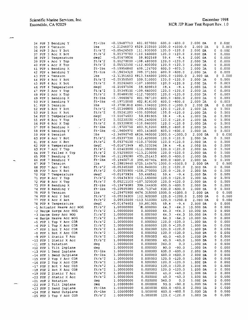
44 PUP 4 Acc Y Bot 45 PUP 4 Acc X Bot 46 PUP 4 Tempera tu re 47 PUP 5 ACC Y Top 48 PUP 5 Acc X Top 49 PUP 5 Bending X 50 PUP 5 Bending Y 5 1 PUP 5 T e n s l o n 52 PUP 5 Acc Y Bot 53 PUP 5 Acc X Bot 54 PUP 5 Tempera tu re 55 PUP 6 ACC Y Top 56 PUP 6 Acc X Top 57 PUP 6 Bending X 58 PUP 6 Bending Y 59 PUP 6 T e n s i o n 60 PUP 6 Acc Y Bot 61 PUP 6 Acc X Bot 62 PUP 6 Tempera tu re 63 PUP 7 ACC Y Top 64 PUP 7 Acc X Top 65 PUP 7 Bending X 66 PUP 7 Bending Y 67 PUP 7 T e n s i o n 68 PUP 7 Acc Y Bot 69 PUP 7 Acc X Bot 70 PUP 7 Tempera tu re 7 1 PUP 8 Acc Y Top 72 PUP 8 Acc X Top 73 PUP 8 Bending X 74 PUP 8 Bending Y 75 PUP 8 T e n s i o n 76 PUP 8 Acc Y Bot 77 PUP 8 Acc X Bot 78 PUP 8 Tempera tu re -1 A c t u a t o r Heave Acc NOG -2 Barge S u r g e Acc NOG -3 Barge Sway A c c NOG -4 Barge Heave Acc NOG -5 PUP 1 Top Y ACC COR -6 PUP 1 Top X ACC COR -7 PUP 1 Bot Y AcC COR -8 PUP 1 Bot X ACC COR -9 PUP 1 S t a t i c Y Acc
-10 PUP 1 S t a t i c X Acc -11 PUP 1 R o t a t i o n -12 PUP 1 T i l t I n p l a n e -13 PUP 1 Bend I n p l a n e -14 PUP 1 Bend O u t p l a n e -15 PUP 2 Top Y ACC COR -16 PUP 2 TOP X ACC COR -17 PUP 2 Bot Y ACC COR -18 PUP 2 Bot X Acc COR -19 PUP 2 S t a t i c Y Acc -20 P U P 2 S t a t i c X A c c -21 PUP 2 R o t a t i o n
-22 PUP 2 T i l t I n p l a n e -23 PUP 2 Bend I n p l a n e -24 PUP 2 Bend Outp lane -25 PUP 3 Top Y A c c COR -26 PUP 3 TOP X AcC COR -27 PUP 3 BOt Y AcC COR -28 PUP 3 BOt X ACC COR -29 PUP 3 S t a t i c Y A c c -30 PUP 3 S t a t i c X Acc -31 PUP 3 R o t a t i o n -32 PUP 3 T i l t I n p l a n e -33 PUP 3 Bend I n p l a n e -34 PUP 3 Bend O u t p l a n e
f t / s A 2 f t / s A 2 degC f t / s A 2 f t / s A 2 f t - l b s i t - l b s l b s f t / s A 2 f t / s A 2 degC f t / s A 2 f t / s A 2 i t - l b s f t - l b s l b s f t / s A 2 f t / s A 2 degC f t / s A 2 f t / s A 2 f t - l b s i t - l b s l b s f t / s A 2 f t / s A 2 degC f t / s A 2 f t / s A 2 f t - l b s f t - l b s 1 b s f t / s A 2 f t / s A 2 degC f t / s A 2 f t / s A 2 f t / s A 2 f t / s A 2 f t / s A 2 f t / s A 2 f t / s A 2 f t / s A 2 f t / s A 2 f t / s A 2 d e g d e g f t - l b s f t - l b s f t / s A 2 f t / s A 2 f t / s A 2 f t / s A 2 f t / s A 2 f t / s A 2 d e 9
d e g f t - l b s f t - l b s f t / s A 2 f t / s A 2 f t / s A 2 f t / s A 2 f t / s A 2 f t / s A 2 d e g d e g f t - l b s f t - l b s

Scientific Marine Services, Inc. Escondido, CA 92029
December 1998 HCR JIP Riser Test Report Rev. 1.0
that should be compared against the THRESHOLD needs to be followed by a letter corresponding to the desired statistic (A,R,X,M,D and S). When more than one channel in selected, any one channel above the THRESHOLD will cause all channels to be saved.
LWSCR Calibration File
HCR JIP Monitoring System CIO-DAS08 14 300 IRQ7 8.319735 330 Y 1 <-- Number of Secondary Devices Following SER-STIM 64 COM2 57600 nodeid.txt chancdw.txt 8 4 <-- Number of Derived Channels 40.000000 <-- SampleRate (Hz) S <-- Storage Mode: (C) ontinuous; (T) hreshold; (0) p Control; (I) nterval; (S)tart/Stop 0 <-- Storage Length (minutes): Threshold 6 Operator Control Storage Mode only 0 <-- Interval Modulus (every Nth Process Interval) - Interval Storage mode only Y <-- Statistical Calculations - (Y)es or (N)o N <-- Statistical Threshold Checking - (Y)es or (N)o - Continue 6 Interval mode only 0 <-- Number of sample to skip when plotting (0 for no skips) 5 <-- Process Interval ( 1 , 2 , 3 , 4 , 5 , 6 , 1 0 , 1 2 , 1 5 , 2 0 , 3 0 , 6 0 ) N <-- Transmit Data COM2 - (Y)es or (N)o 0 <-: Number of samples to skip when transmitting (0 for no skips) Y <-- Store SYSTEM log entries - (Y)es or (N)o c:\hcrdata <-- Data Storage Path ........................................................................................................ -------- - CH# <-CHANNEL NAME-----
TRIGGER ........................ - - - - - - - - -
1 Actuator Load 2 Pipe Pitch 3 Pipe Pitch Rate 4 Pipe Roll 5 Pipe Roll Rate 6 Accuator Heave Acc 7 Barge Roll 8 Barge Roll Rate 9 Barge Pitch
10 Barge Pitch Rate 11 Barge Surge Acc 12 Barge Sway Acc 13 Barge Heave Acc 14 Empty Channel 15 PUP 1 Acc Y Top 16 PUP 1 Acc X Top 17 PUP 1 Bending X 18 PUP 1 Bending Y 19 PUP 1 Tenslon 20 PUP 1 Acc Y Bot 21 PUP 1 Acc X Bot 22 PUP 1 Temperature 23 PUP 2 Acc Y Top 24 PUP 2 ACC X Top 25 PUP 2 Bending X 26 PUP 2 Bending Y 27 PUP 2 Tension 28 PUP 2 Acc Y Bot 29 PUP 2 Acc X Bot 30 PUP 2 Temperature 31 PUP 3 Acc Y Top 32 PUP 3 Acc X Top 33 PUP 3 Bending X 34 PUP 3 Bending Y 35 PUP 3 Tension 36 PUP 3 Acc Y Bot 37 PUP 3 Acc X Bot 38 PUP 3 Temperature
lbs deg deg/s deg deg/s ft/sA2 deg deg/s deg deg/s ft/sA2 ft/sA2 ft/sA2 lbs ft/sA2 ft/sA2 ft-lbs ft-lbs lbs ft/sA2 ft/sA2 degC ft/sA2 ft/sA2 ft-lbs ft-lbs lbs ft/SA2 f t/sA2 degC ft/sA2 ft/sA2 ft-lbs ft-lbs lbs ft/sA2 ft/sA2 degC
.-> <-SLOPE INTERCEPT MAXSCALE MINSCALE DELTA STAT TX THRESHOLD

Scientific Marine Services, Inc. Escondido, CA 92029
December 1998 HCR JIP Riser Test Report Rev. 1.0
-31 PUP 3 Rotation -32 PUP 3 Tilt Inplane -33 PUP 3 Bend Inplane -34 PUP 3 Bend Outplane -35 PUP 4 Top Y ACC COR -36 PUP 4 Top X Acc COR -37 PUP 4 Bot Y Acc COR -38 PUP 4 Bot X ACC COR -39 PUP 4 Static Y Acc -40 PUP 4 Static X Acc -41 PUP 4 Rotatlon -42 PUP 4 Tilt Inplane -43 PUP 4 Bend Inplane -44 PUP 4 Bend Outplane -45 PUP 5 Top Y ACC COR -46 PUP 5 TOP X ACC COR -47 PUP 5 Bot Y ACC COR -48 PUP 5 Bot X ACC COR -49 PUP 5 Static Y Acc -50 PUP 5 Static X Acc -51 PUP 5 Rotation -52 PUP 5 Tilt Inplane -53 PUP 5 Bend Inplane -54 PUP 5 Bend Outplane -55 PUP 6 TOP Y ACC COR -56 PUP 6 TOP X ACC COR -57 PUP 6 Bot Y ACC COR -58 PUP 6 Bot X ACC COR -59 PUP 6 Static Y Acc -60 PUP 6 Static X Acc -61 PUP 6 Rotation -62 PUP 6 Tilt Inplane -63 PUP 6 Bend Inplane -64 PUP 6 Bend Outplane -65 PUP 7 Top Y Acc COR -66 PUP 7 Top X ACC COR -67 PUP 7 Bot Y Acc COR -68 PUP 7 Bot X ACC COR -69 PUP 7 Static Y Acc -70 PUP 7 Static X Acc -71 PUP 7 Rotation -72 PUP 7 Tilt Inplane -73 PUP 7 Bend Inplane -74 PUP 7 Bend Outplane -75 PUP 8 TOP Y ACC COR -76 PUP 8 Top X ACC COR -77 PUP 8 Bot Y ACC COR -78 PUP 8 Bot X Acc COR -79 PUP 8 Static Y Acc -80 PUP 8 Static X Acc -81 PUP 8 Rotation -82 PUP 8 Tilt Inplane -83 PUP 8 Bend Inplane -84 PUP 8 Bend Outplane
deg deg ft-lbs ft-lbs ft/sfi2 ft/sA2 ft/sA2 ft/sA2 ft/sA2 ft/sA2 deg deg ft-lbs ft-lbs ft/sA2 ft/sA2 ft/sA2 ft/sA2 ft/se2 ft/sA2 deg deg ft-lbs fc-lbs ft/sn2 ft/sA2 ft/SA2 ft/SA2 ft/sn2 ft/sA2 deg deg ft-lbs ft-1bs ft/S^2 ft/sA2 ft/s*2 ft/sA2 ft/sA2 ft/sA2 deg deg ft-lbs ft-lbs ft/sA2 ft/sA2 ft/s"2 ft/sA2 ft/sA2 ft/s"2 deg deg ft-lbs ft-lbs
Notes : STAT has the following format: xy where
x is the processing interval to use D - Display Stats P - PROCINT Stats T - Test Stats
y is the statistic A - Average (mean) R - Standard deviation X - maximum M - Minimum D - Double Amplitude Significant (4 X Stdev) S - Single Amplitude Significant (2 X Stdev)
i.e. PA is the Average over the PROCINT processing interval
Scientific Marine Services, Inc. Escondido, CA 92029
December I998 HCR JIP Riser Test Report Rev. 1.0
34 PUP 3 Bending Y 35 PUP 3 Tension 36 PUP 3 Acc Y Bot 37 PUP 3 Acc X Bot 38 PUP 3 Temperature 39 PUP 4 Acc Y Top 40 PUP 4 Acc X Top 41 PUP 4 Bending X 42 PUP 4 Bending Y 43 PUP 4 Tension 44 PUP 4 Acc Y Bot 45 PUP 4 Acc X Bot 46 PUP 4 Temperature 47 PUP 5 ACC Y Top 48 PUP 5 Acc X Top 49 PUP 5 Bending X 50 PUP 5 Bending Y 51 PUP 5 Tension 52 PUP 5 ACC Y B0t 53 PUP 5 Acc X Bot 54 PUP 5 Temperature 55 PUP 6 Acc Y Top 56 PUP 6 Acc X Top 57 PUP 6 Bending X 58 PUP 6 Bending Y 59 PUP 6 Tension 60 PUP 6 Acc Y Bot 61 PUP 6 Acc X Bot 62 PUP 6 Temperature 63 PUP 7 Acc Y Top 64 PUP 7 Failed X Top 65 PUP 7 Bending X 66 PUP 7 Bending Y 67 PUP 7 Tension 68 PUP 7 Acc Y Bot 69 PUP 7 Acc X Bot 70 PUP 7 Temperature 71 PUP 8 Acc Y Top 72 PUP 8 Acc X Top 73 PUP 8 Bending X 74 PUP 8 Bending Y 75 PUP 8 Tension 76 PUP 8 Acc Y Bot 77 PUP 8 Acc X Bot 78 PUP 8 Temperature -1 Actuator Heave Acc NC -2 Barge Surge Acc NOG -3 Barge Sway Acc NOG -4 Barge Heave Acc NOG -5 PUP 1 TOP Y ACC COR -6 PUP 1 TOP X ACC COR -7 PUP 1 Bot Y ACC COR -8 PUP 1 Bot X ACC COR -9 PUP 1 Static Y Acc
-10 PUP 1 Static X Acc -11 PUP 1 Rotation -12 PUP 1 Tilt Inplane -13 PUP 1 Bend Inplane -14 PUP 1 Bend Outplane -15 PUP 2 Top Y A c ~ COR -16 PUP 2 TOP X ACC COR -17 PUP 2 Bot Y ACC COR -18 PUP 2 Bot X ACC COR -19 PUP 2 Static Y Acc -20 PUP 2 Static X Acc -21 PUP 2 Rotation
4 *A -22 PUP 2 Tilt Inplane -23 PUP 2 Bend Inplane -24 PUP 2 Bend Outplane -25 PUP 3 Top Y Acc COR
ft-lbs lbs ft/se2 ft/se2 degC ft/se2 ft/sA2 ft-lbs ft-lbs lbs ft/sA2 ft/sA2 degC f t /sA2 ft/sA2 ft-lbs ft-lbs 1 bs ft/sA2 f t/sA2 degC ft/sA2 ft/sA2 ft-lbs ft-lbs lbs ft/sA2 ft/sA2 degC ft/sA2 ft/sA2 ft-lbs ft-lbs lbs ft/sA2 ft/sA2 degC ft/sA2 ft/sA2 ft-lbs ft-lbs lbs ft/sA2 ft/sA2 degC
)G ft/sA2 ft/sA2 ft/sA2 ft/sA2 f t/sA2 ft/sA2 ft/se2 ft/sA2 ft/sA2 ft/sA2 deg deg ft-lbs ft-lbs ft/sA2 ft/sA2 ft/sA2 ft/sA2 ft/sA2 ft/sA2 deg deg ft-lbs ft-lbs ft/sA2

Scientific Marine Services, Inc. Escondido. CA 92029
December 1998 HCR JIP Riser Test Report Rev. 1.0
M - Mlnimum D - Double Amplitude Significant ( 4 X Stdev) S - Single Amplitude Significant ( 2 X Stdev)
i.e. PA is the Average over the PROCINT processing interval
THRESHOLD is used for Threshold Storage Mode and Statistical Threshold Checking. When uslng Threshold Storage Mode, any channel that should be compared against the THRESHOLD needs to be followed by the letter 'T'. When using Statistical Threshold Checking, any channel's statistics that should be compared against the THRESHOLD needs to be followed by a letter corresponding to the desired statistic (A,R,X,M,D and S). When more than one channel in selected, any one channel above the THRESHOLD will cause all channels to be saved.

Scientific Marine Services, Inc. Escondido, CA 92029
December 1998 HCR JIP Riser Test Report Rev. 1.0
Appendix B
Load Cell Calibration Certification Sheet

Scientific Marine Services, Inc. Escondido, CA 92029
December 1998 HCR JIP Riser Test Report Rev. 1.0
Appendix C
Time Series, PSD Plots, and Statistics Sheets for Select CVAR Motions


it: m II

C C u u o o 0 0 .d .ri Z Z U U
U u rn rn u u o o 4 ~ a a


0.9
0 8
0 7
n 0 al Y' Nn
V
, .€ U) c
d .I- 0 al (1 c9
0.3
0
Frequency (Hertz)
Power Spectral Density Plot of Pup 5 Y Position (cvar amp = .5 ft period = 10 seconds 08120198 16:01:38)
H sig = 0.53005 ft T peak = 10.5714 seconds Tz = 10.682 seconds mO = 0.017559 ft2 m l = 0.0016218 $IS m2 = 0.00015389 $Is2 m3 = 1.61 91 e-005 ft21s3 m4 = 5.7666e-006 $Is4 Number of points = 2960 Points smoothed = 1 Number of passes = 1 Sample Rate = 40 Hz Bandwidth = 0.01 351 4 Hz
. Spectral bandwidth = 0.87528
I I I I I
I I 1--- -7 I I I
I I I I I I I I I I I I
I I I I I I
- - - -
- - -
I I I I I I
I I I I I I
- - - - I I I I I I r - - - - - - - - , - - - - - - - - 7 - - - - - - - - - I - - - - - - - - - r - - - - - - - - r - - - - - - - - -
I I I I I I I I I I I I
I I I I I I I I I I I I
I I I I I I I I I I I I
- - - - - - - - I I I I I
I I I I I I I I I I I I I I I I I I I I I I I I
I I I I I I I I I I I I I I I I I I
~ . ~ - - - - - - - - L - - - - - - - - J - - - - - - - - J - - - - - - - - - ~ - - - - - - - - - L - - - - - - - - L - - - - - - - - . I I I I I I
I I I I I I I I I I I I I I I I I I I I I I I I I I I I I I
I I I I I I
s o . ~ 5 - - - - - - - - L - - - - - - - - J - - - - - - - - J - - - - - - - - - l - - - - - - - - - L - - - - - - - - L - - - - - - I I I I I I I I I I I I I I I I I I
I I I I I I
2
-
1 I I I I I I I I
I I I I I I I I I I I I I I I I I I
o . 4 - - - - - - - - ' - - - - - - - - ' - - - - - - - - - ' - - - - - - - - - ' - - - - - - - - - ' - - - - - - - - ' - - - - - - - - ' - - - - - - - - J - - - - - - - - - ~ - - - - - - - - - I I I I I I I I I I I I I I I I I
I I I I I I I I I
I I I I I I I I I
I I I I I I I I I I I I I I I I I I
I I I I I I I I I
I I I I I I I I r - - - - - - - - l - - - - - - - - l - - - - - - - - - - - - - - - - - - - - - - - - - r - - - - - - - - r - - - - - - - - l - - - - - - - - l - - - - - - - - - I - - - - - - - - - I I I I I I I I I I I I I I I I I I
I I I I I I I I I
I I I I I I I I I I I I I I I I I I
I I I I 1 I I I I I I . 0 2 - - . - - - - - : - - - - - - - - : - - - - - - - - 1 - - - - - - - - - ; - - - - - - - - - r - - - - - - - - : - - - - - - - - 3 - - - - - - - ; - - - - - - - - - ; - - - - I
I I I I I I I I I I I I I I I I I I
I I I I I I I I I I I I I I I I I I
I I I I I I I I I I I I I I I I I I
I I I I I I I I I o 1 - - . . - - - - - t - - - - - - - - 4 - - - - - - - - 4 - - - - - - - - - I - - - - - - - - - C - - - - - - - - t - - - - - - - - 4 - - - - - - - - 4 - ~ ~ ~ ~ ~ ~ ~ ~ l ~ ~ ~ ~ . ~ ~ ~
I I I I I I I I I I I I I I I I 1 I
I I I I I I I I I
I I I I I I I I I
-
0 i - - - j L
I I I I I I I I I I I
I I
0.2 0.4 0.6 0.8 1 1.2 1.4 1.6 1.8


Scientific Marine Services, Inc. Escondido, CA 92029
December 1998 HCR JIP Riser Test Report Rev. 1.0
Appendix D
Plots From Specified Select Data Runs

Actuator Load (Ibs) m 6, tn a, 0, -l -l 0 N P tn 03 0 N
NO 0 0 0 0 0 0
I
0

PUP 1 Bend lnplane COR (ft-lbs)

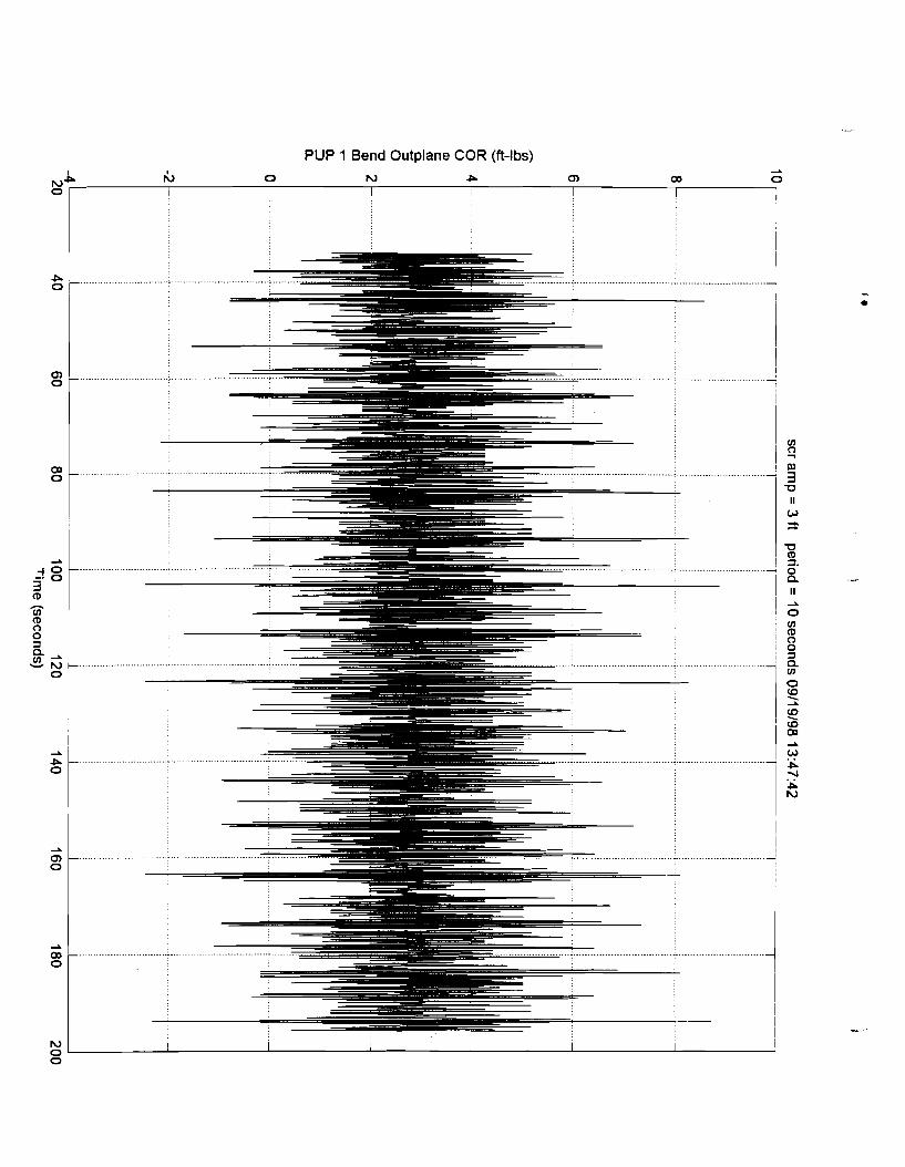
PUP 1 Bend Outplane COR (ft-lbs)

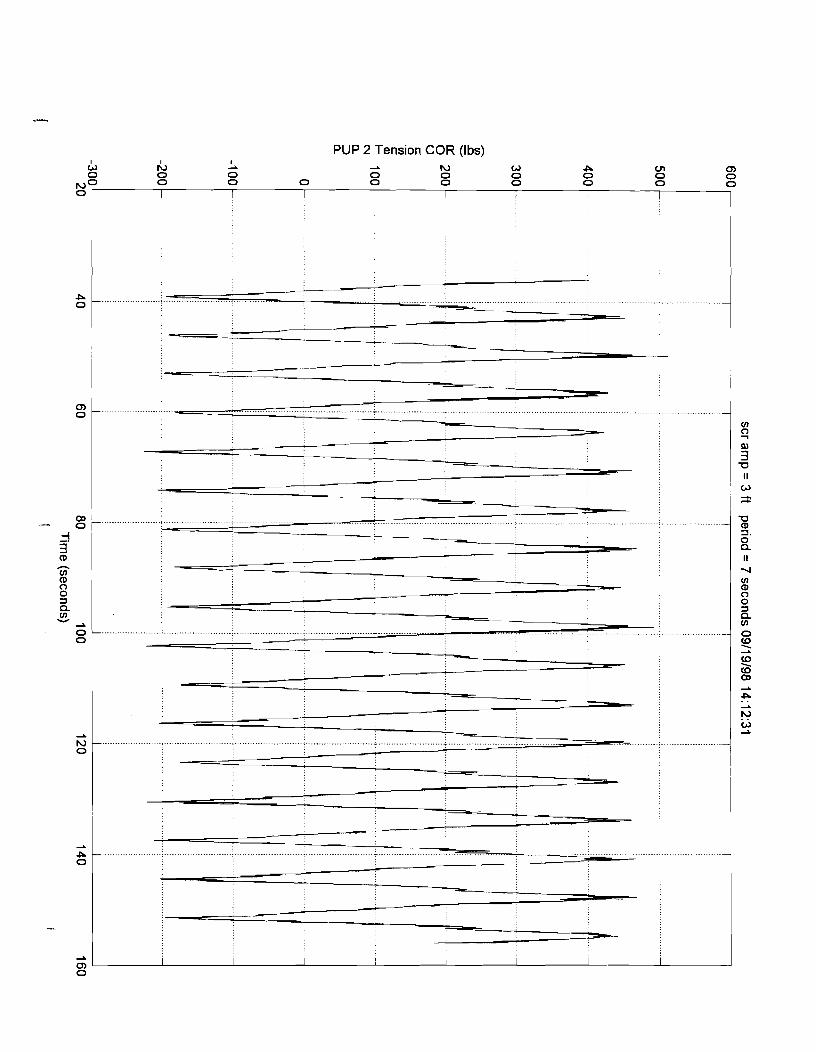
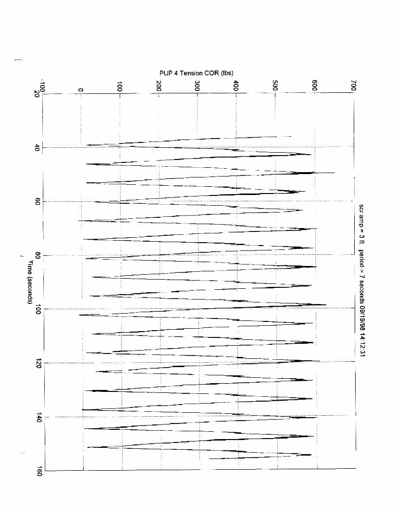
PUP 1 Tension COR (Ibs)

PUP 2 Bend l n ~ l a n e COR (ft-lbs)

PUP 2 Bend Outplane COR (ft-lbs)

PUP 2 Tension COR (Ibs)

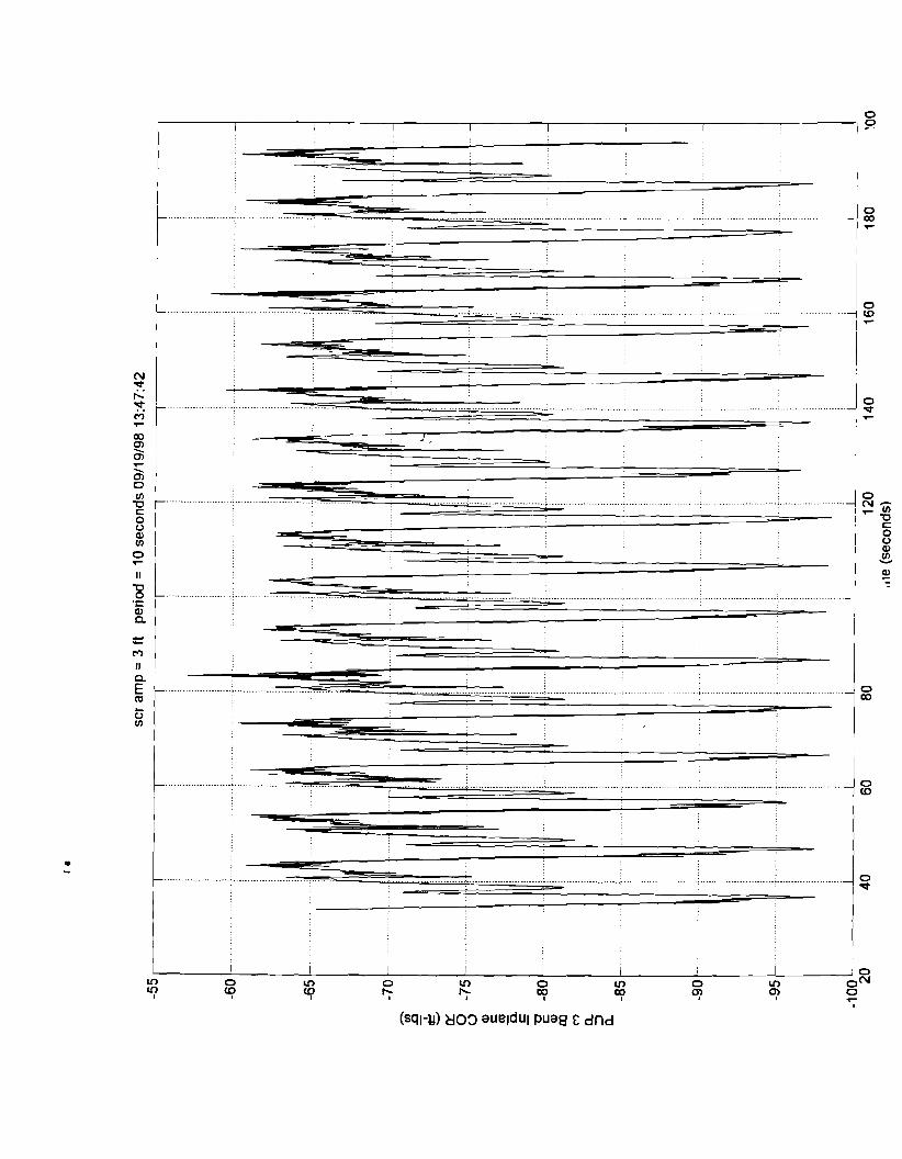
PUP 3 Bend Outplane COR (it-lbs)

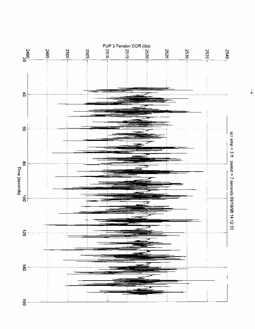
PUP 3 Tension COR (Ibs)

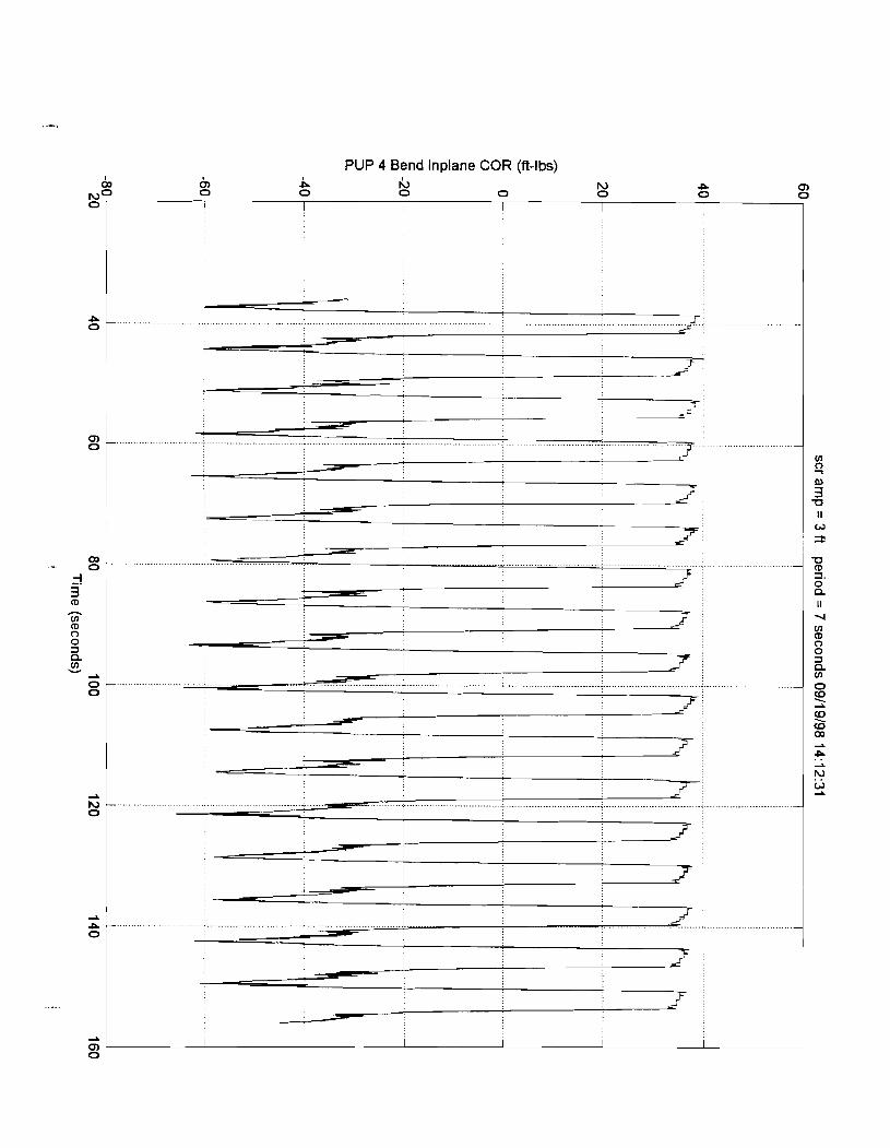
PLlP 4 Bend lnplane COR (ft-lbs)

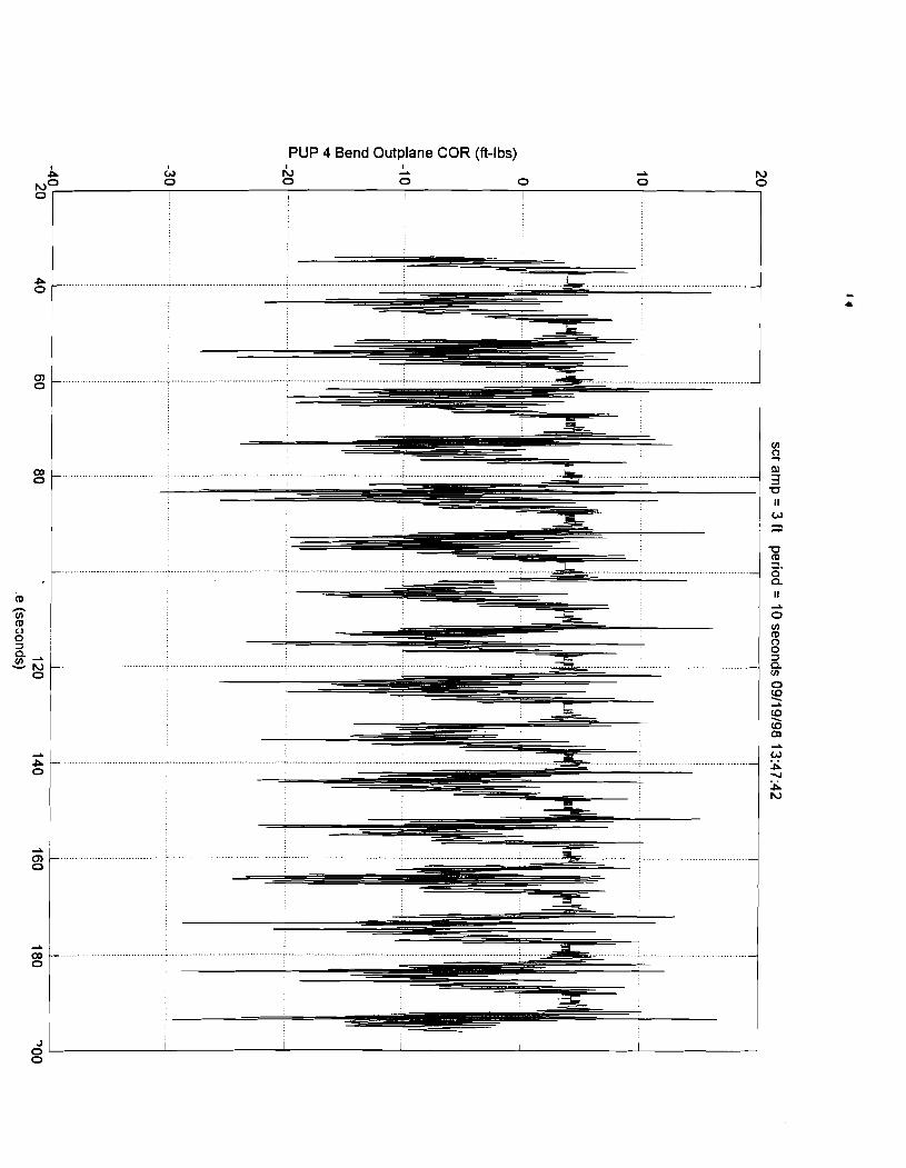
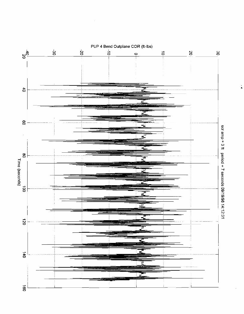
PUP 4 Bend Outplane COR (ft-lbs)

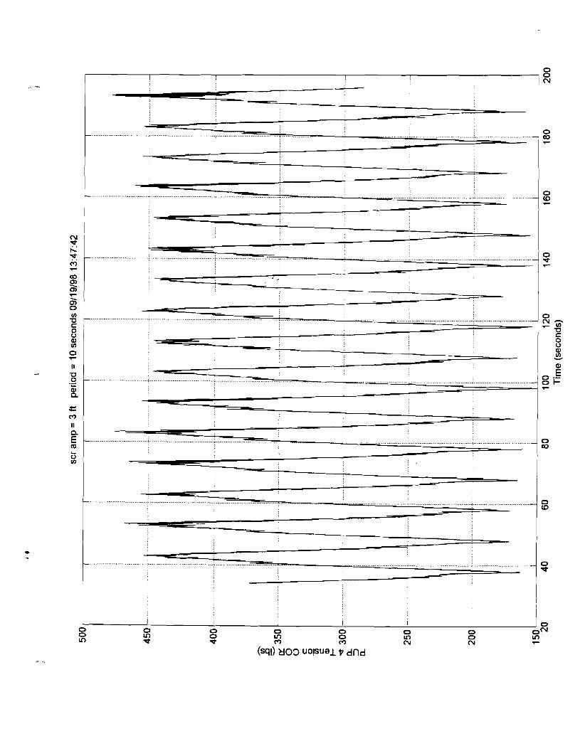
PUP 4 Tension COR (Ibs)

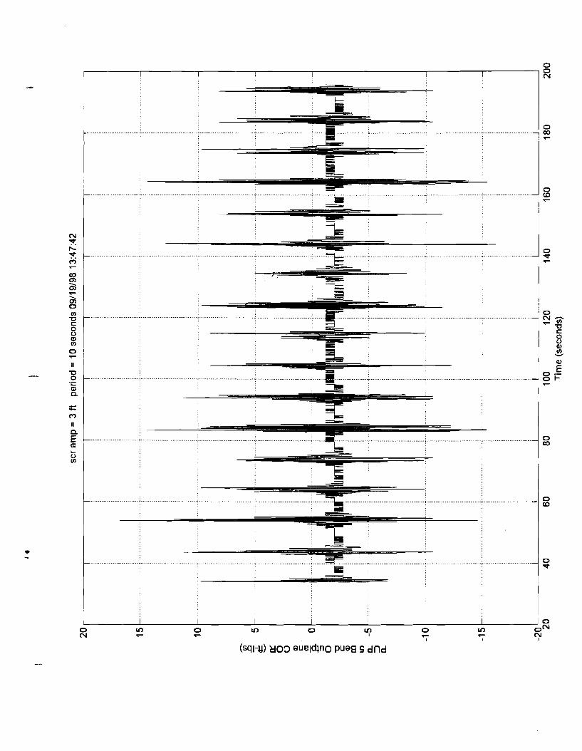
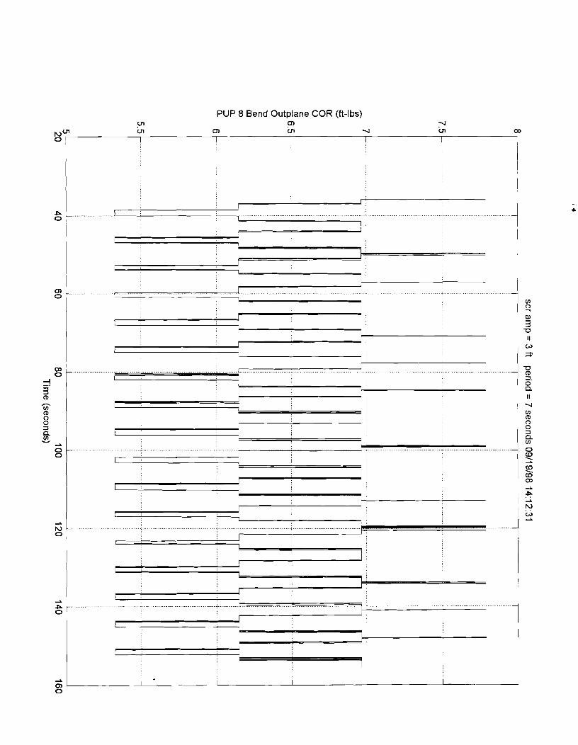
PUP 5 Bend Outplane COR (ft-lbs)

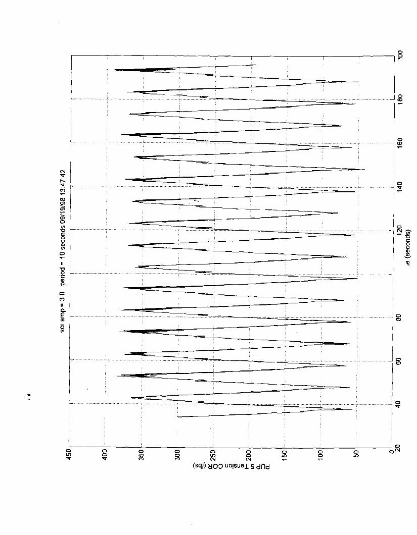
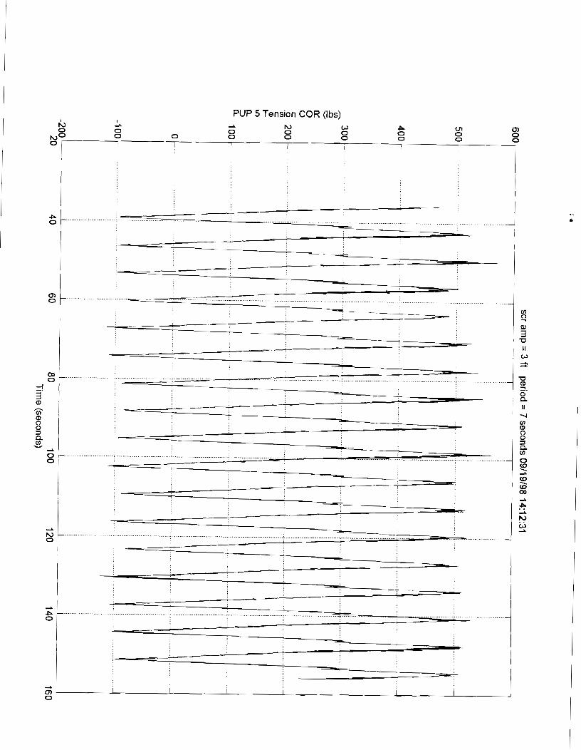
PUP 5 Tension COR (Ibs)

PUP 6 Bend lnplane COR (ft-lbs)

PUP 6 Bend Outplane COR (ft-lbs) A A N N W W
ul 0 P
NO ul 0 ul P
0
0 I I I I I I I 4 I I I I


PUP 7 Bend Outplane COR (ft-lbs)

PUP 7 Tension COR (Ibs)

PUP 8 Bend lnplane COR (ft-lbs) 2 A A A
CD CD 0 0 A 2
NO CJl 0 CJl 0 CJl & 0 I I I (
I 1 I I I
I I I I I 1
%==- I I I I I I I I
I I
0 c : 2 -a
II W ;?
-a 2. 0 a II 2
0 V) (D 0 0 =1 a V)
0 Q, \
3 z Q,
0 r, W 2 . . 2
(D
0
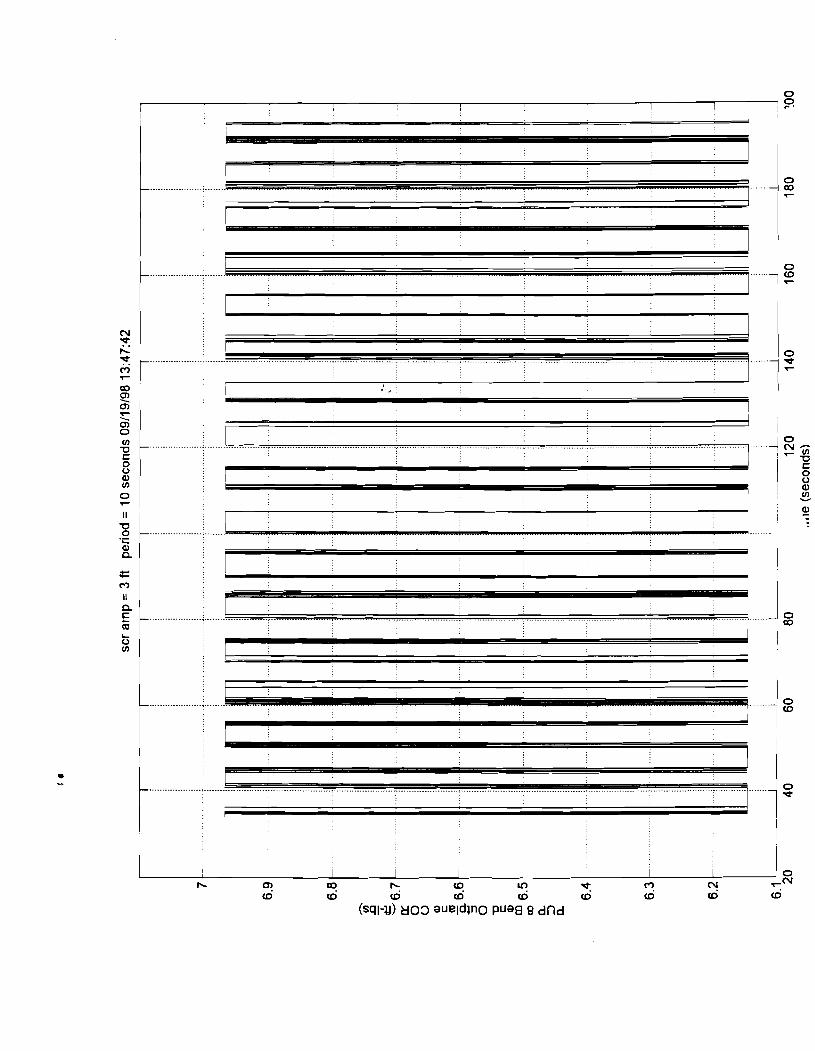
PUP 8 Bend Outplane COR (ft-lbs) I CJl 0 U1

PUP 8 Tension COR (Ibs)

Pup 1 X Position (ft)

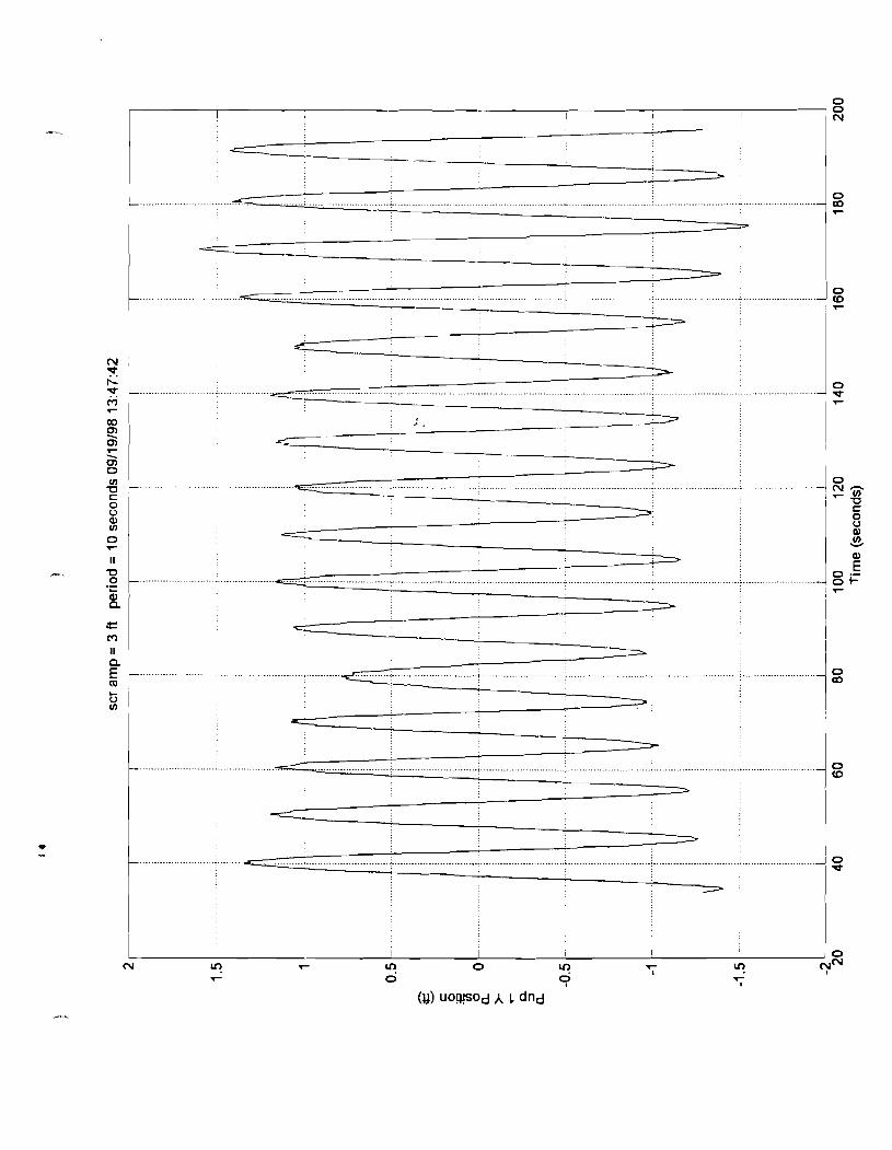
Pup 1 Y Position (ft)


Pup 2 Y Position (ft) . . 0 0 0 0 P 0
Nip 0, b iu 0 N b P 0 I I I I 1 I
I

Pup 3 X Position (ft) ~b ld rb A o A h) w 5
I
P 0 I I I I 1 I I
I ! I I I ,
Pup 3 Y Position (ft)

Pup 4 Y Position (ft)

Pup 5 X Position (ft)

Pup 5 Y Position (ft) P P 0 o a Z a a
2 b , s 0 P m- 0) Q) I I P
I I
P 1 I I 1 I 0 , I I I I I
I I I I I I ,
I I I \ I
I I I I I I I
I I I I I I I
I I I 1
I I
I I I I
I I I I
2 %
5 u
I It o 1 - - - , - - - _ - - - L - - - - _ - A _ - - - - - - I - - - - - - - L L L L L L - _ I - - - - - - - L - - - - - - L - - - - - - - I 0 0
: m c : % 0 2 a U1 V
g 0
g 0
I I
i - - - - - l-, I I I I 1
I I I I I I 1
I I I I I I I
I / I I I
I I I I I I I I
I I I
I I I , I I
I I I I I I I
I I I
I I I 1 I -. , I I I I I I
I I I I
I I I
-- - - - - &- - - - - - ; - - - - - - - '
I , I 1 I
r - - - - - - l - - - - - - - l - - - - - - - r - - - - - - l - - - - - - I -; ------; - - - - - - -
I I I I I \ I
I I 1 I I I L I I I
I I I I 1 I I
a I I I I I
I I I
I I I I I I
I I I I I I I I I
I I I I I I I , I
I c I I I I I I I
I I I I I I
- _ - _ - L - _ - _ - _ i _ - _ - - - - l - - - - - - - L - - - - - - l - - - - - - - L - - - - - - l - - - - - - - I I
-- - - - - -: -- - - - -1- - I I 1 I I I I
I I I I I I I I I
I I 2 I I I I I
I I I I I I I
I I I I
I I I I I
c - - 1 I I
I I I I I I I I I
I I I I
I I I I I I I I 3
I I I I \ I , I
I I I I 1 I
I I r - - - - - - 7 - - - - - - - - - - - - - -
;:- - - - - - += ..--- ' I I
_ ( _ - - - - - - I r - - - - - - 7 - - - - - - - I r - - - - - - ; - - - - - - - I I I
I I I I I I
I I I I I I Li.
I I I I I I I
I I I I I I I 1 I
I I I I I
4 I I I I I I
I I I I I I , I
I I I / I I I I I
I I l
G,
;?
-0
z. 0 n II 2
0 V) m 0 0 3 a V)
0 e !2 \
(D 0)
0 5' 2 . . 2
(D
I I 1 I I
I I
I I 0
I I I 1 I I I I 0
P 0
! I I I
I I I I 2 I I 1 I
I 1 I I I I I I I
1 I I I , I I
I I I I
I I I I I I I 1
I I I I I I I I I I I
I 1 I 2 1 , I I I I
I I I I
1 1 1 I
1 I I I I I I I
0

Pup 6 X Position (ft)
Ic, I 2
1 0 0 A
rC, 2 -L NU1 Ln rn 0 vl U1 N ru
P rn
0 I I , I
I I I I I I I
I I I I I I I I I i

Pup 6 Y Position (ft)

Pup 7 X Position (ft)

Pup 7 Y Position (ft)

Pup 8 X Position (ft) I 2
NO CD Cn b rC, 0 N P cn m 2
P 0
0 I I I I I I I I I I 1
Pup 8 Y Position (ft) I I I I
P h)Co a X R o h) X P P
GI P CD
P 0 I I I I I I I
I I I I I I I


E (El L
(El > 0


(sql) a03 uo!sual L dfld


L.. I


PUP 4 Bend Outplane COR (ft-lbs)


(sql-~) 803 aueldln0 Pua0 9 dfld


PUP 7 Bend Outplane COR (ft-lbs)


PUP 1 Bend lnplane COR (ft-lbs) I I I I I a I
A A A A A A r;, + rl, A
"' "' 0 (0 OJ CD V1 P W 0 I I I I I I I I
I
PUP 1 Bend Outplane COR (ft-lbs)


PUP 4 Bend lnplane COR (ft-lbs)
PUP 4 Bend Outplane COR (ft-lbs)


Actuator Load (Ibs)


PUP 1 Bend Outplane COR (ft-lbs)

PUP 1 Tension COR (Ibs)

PUP 2 Bend lnplane COR (ft-lbs)

PUP 2 Bend Outplane COR (ft-lbs)

PUP 2 Tension COR (Ibs)


PUP 3 Bend Outplane COR (ft-lbs)

PUP 3 Tension COR (Ibs)


Actuator Load (Ibs)

PUP 1 Bend lnplane COR (ft-lbs) rC1 rC1 tL I I I I
2 2 2 2
NP N 0 03 0 P N 0 I 1 I I I I
PUP 1 Bend Outplane COR (ft-lbs) I 2 2 2
NO b rl, 0 N P m 0) 0 N P 0 I I I I I I I I I I
I

PUP 1 Tension COR (Ibs)

PLlP 2 Bend lnplane COR (I?-lbs)

PUP 2 Bend Outplane COR (ft-lbs) do ir, b rC, N P
0 0 0 m
NO 0 0 0 0 0 1 I I I I 1 i I
I
PUP 2 Tension COR (Ibs)

0
.......................
........ , ......................
I 1 I I I I 1 0 0 0 0 0 0 0 0 0 - 0
0 (V m om
9 9' Y * 4 - - - - - Ti-
(sql-~) a03 aueldul E dl7d ' I I I

PUP 3 Bend Outplane COR (ft-lbs)
PUP 3 Tension COR (Ibs)
PUP 4 Bend lnplane COR (fi-lbs) b 6, b
0 rC,
0 0 N P
0 0 0 Q) 0
I I I I I
PUP 4 Bend Outplane COR (ft-lbs)
PUP 4 Tension COR (Ibs)

PUP 5 Bend lnplane COR (ft-lbs) I I 2 b b la la rl, rl, 2
N'" 0 VI 0 m 0 VI 0 Ln 0 m 0 I I I I I I I
=! 3 (D
U) (D 0 0 =1 a U) V
2 1
0, I I I I I I I I I 0

PUP 5 Bend Outplane COR (ft-lbs) I rl, I I
A A A A
I 0 VI 0 dl 0 VI 0 N N
VI 0 VI 1 I 1 I I
I
PUP 5 Tension COR (Ibs)

PUP 6 Bend lnplane COR (ft-lbs) + &J LJ LJ I I I I
I 0 : LJ (D OD 4 01 VI w c 2 CL 0
up 0 I I I I I I I I I
P - 0
-

PUP 6 Bend Outplane COR (ft-lbs) P 2
2 ul N ul W z P 10 P
p3"' VI VI 0 I I I I I I I I
I I
1
I I

PUP 6 Tension COR (Ibs)

PUP 7 Bend lnplane COR (ft-lbs)
I I I . .

PUP 7 Bend Outplane COR (ft-lbs) I I I I I I I
--L --L * * * 2 2 I
No' P N rC, m a, P N A
0 ,I

PUP 7 Tension COR (Ibs)
PUP 8 Bend lnplane COR (ft-lbs) I I I I I I
2 2 2 2 10 lL bo b, i. rQ rQN 0 I I
PUP 8 Bend Outplane COR (ft-lbs)
z 0) UI 4 UI 03 P, 'r
rduI 01 I I I I I
I i

PUP 8 Tension COR (Ibs)

Pup 1 X Position (ft)

Pup 1 Y Position (ft)

Pup 2 X Position (ft) b b A 0 A rn w A rn
I

Pup 2 Y Position (ft)

Pup 3 X Position (ft)

Pup 3 Y Position (ft)

Pup 4 X Position (ft)

Pup 4 Y Position (ft)

Pup 5 X Position (ft)

Pup 5 Y Position (ft)

Pup 6 X Position (ft)

Pup 6 Y Position (ft)


Pup 7 Y Position (ft)

Pup 8 X Position (ft)

Pup 8 Y Position (ft)


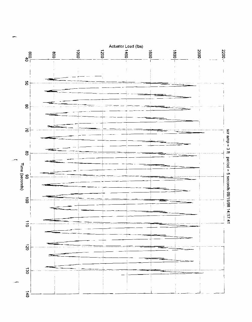
Actuator Load (Ibs)

PUP 1 Bend lnplane COR (ft-lbs)

PUP 1 Bend Outplane COR (ft-lbs) I 2 -L A cln 0 Cn 0
s O v - - - - - i I I

PUP 1 Tension COR (Ibs)

PUP 2 Bend lnplane COR (ft-lbs) b I I I
A !2 2 2
Ln ul 0 0
lJl 0
VI 0 0 0
0
"rO 0 1 I 7_-_---T--
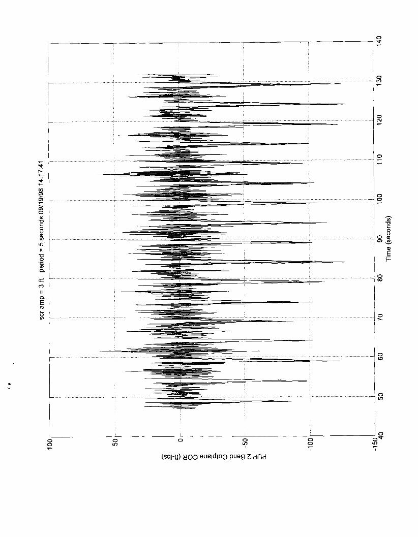

PUP 2 Tension COR (Ibs)

PUP 3 Bend lnplane COR (ft-lbs) I I I I I I
A --L --L a b M a P3 0 0) '3 P N 0 to Q b
PO 0 0 0 0 0 0 0 0 0 0 : I 1 I I I I
.-- .---
a 0 - ....- ........
0 ~ P 1 -
;1 u - a
-. .................................................. 0
a
0
2- - -
............................................ ......................... ............................................ - : : : .........................
..................... --: ................... ; ..-- ' ...-....-....--....--.
4
P I 0

PUP 3 Bend Outplane COR (ft-lbs)
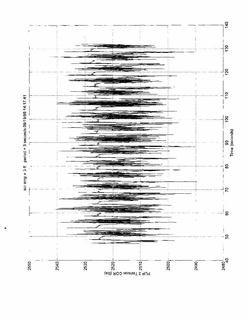


PUP 4 Bend Outplane COR (ft-lbs)

PLlP 4 Tension COR (Ibs)
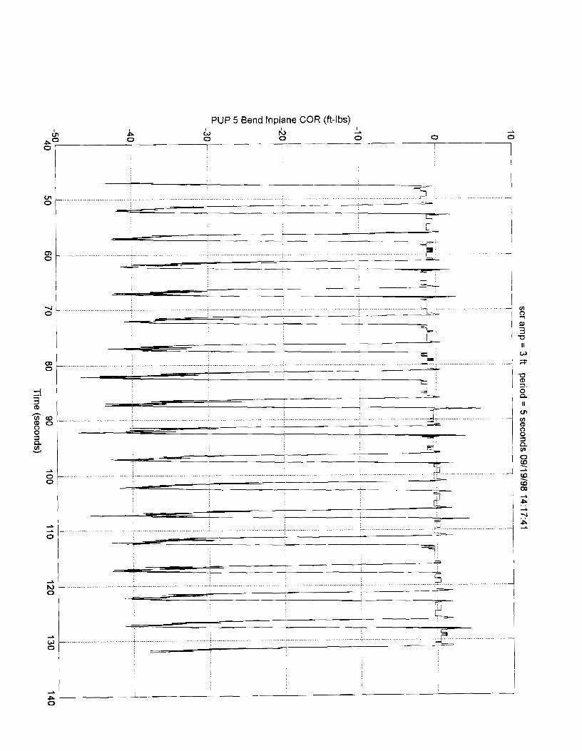
PUP 5 Bend lnplane COR (ft-lbs)

PUP 5 Bend Outplane COR (ft-lbs)
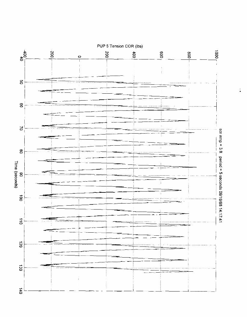
PUP 5 Tension COR (Ibs)

PUP 6 Bend lnplane COR (ft-lbs) I I I I 0 2 A 2 2 -L
Pa Q) P h) 0 & b, b 0 I r I
I I I I 1

PUP 6 Bend Outplane COR (ft-lbs)

PUP 6 Tension COR (Ibs)

PLlP 7 Bend lnplane COR (ft-lbs)
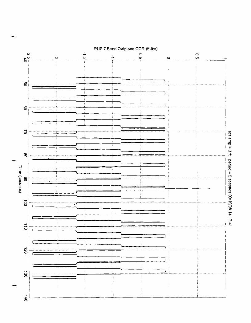
PLlP 7 Bend Outplane COR (ft-lbs) I I
13 2
rC, in VI - 0 m I a a P A'" a
O r - I

PUP 7 Tension COR (Ibs)

PUP 8 Bend lnplane COR (ft-lbs) I I I I I I
2 A A 2 h, I 0 0 ah) rb in 0) 'a Ec, A OD 0)
0 [ E
l 1 I I I 7 7 - - 7

PUP 8 Bend Outplane COR (ft-lbs) P z 9'
cn 4 ?
cn 0, ul 0, PJ
P* * (D 0 a
I

PUP 8 Tension COR (Ibs)

Pup 1 X Position (ft)
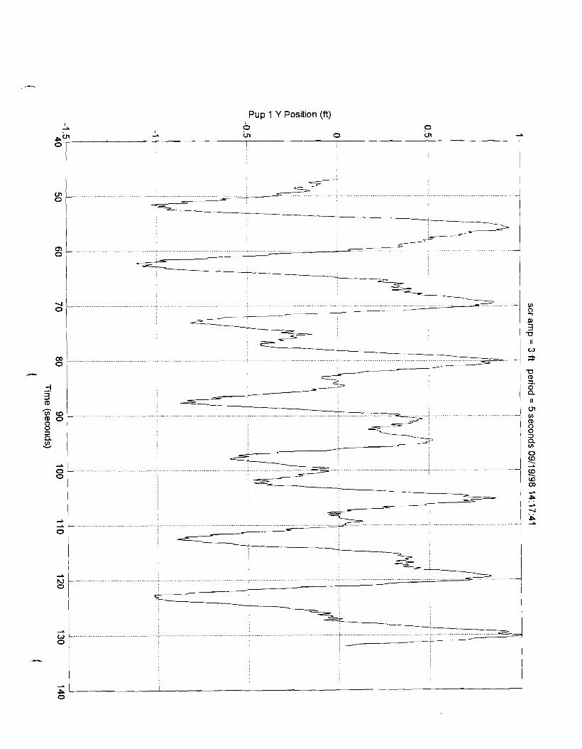
Pup 1 Y Position (ft) I I 2
Pin I 3 z 0 z 2
I I -
0 I
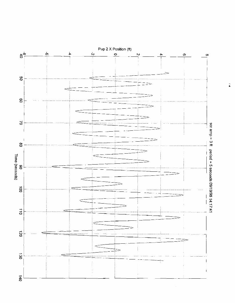
Pup 2 X Position (ft)
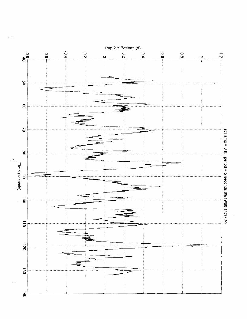
Pup 2 Y Position (ft)

Pup 3 X Position (ft)

Pup 3 Y Position (ft)

Pup 4 X Position (ft)

Pup 4 Y Position (ft)

Pup 5 X Position (ft)

Pup 5 Y Position (ft) 0
I I I I
X P R P P P P 0 R A A A'" W 0 W
I I I I I I I

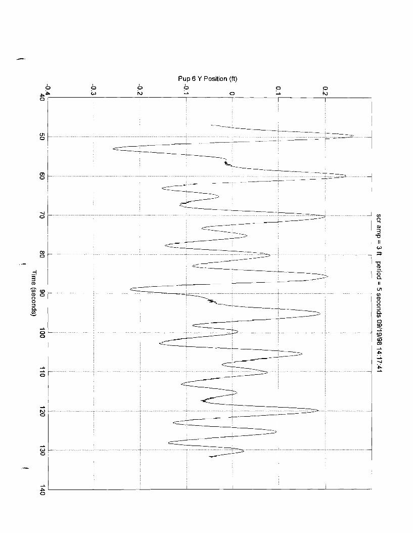
Pup 6 Y Position (ft) 0
I I
P 0 (c, iu -1 0
P P -1
P PP N
2
A I I 1 I I I


Pup 7 Y Position (ft)
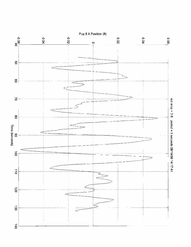
Pup 8 X Position (ft)

Pup 8 Y Position (ft)


PUP 1 Bend Outplane COR (ft-lbs)

PUP 1 Tension COR (Ibs)

PUP 2 Bend lnplane COR (ft-lbs)

PLlP 2 Bend Outplane COR (ft-lbs)

PUP 2 Tension COR (Ibs)


PUP 3 Bend Outplane COR (ft-lbs)


PUP 4 Bend lnplane COR (ft-lbs)

PUP 4 Bend Outplane COR (ft-lbs) I
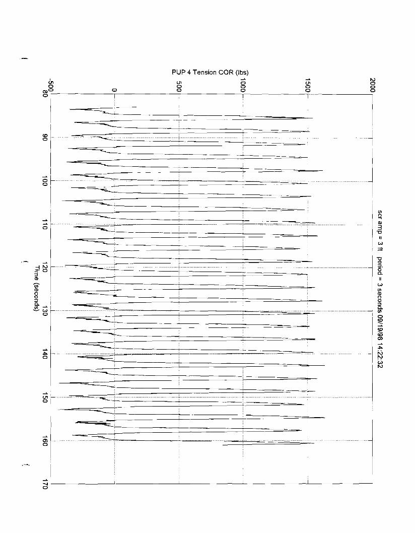
PUP 4 Tension COR (Ibs)

PUP 5 Bend lnplane COR (ft-lbs)
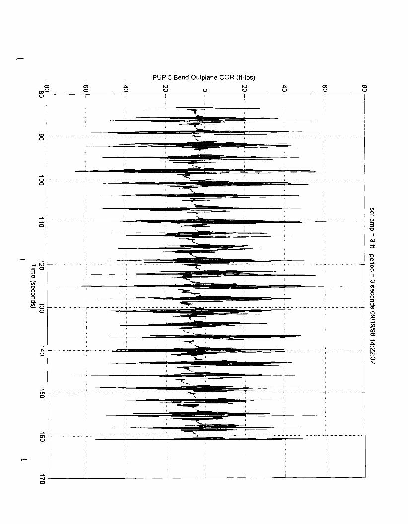
PUP 5 Bend Outplane COR (ft-lbs)
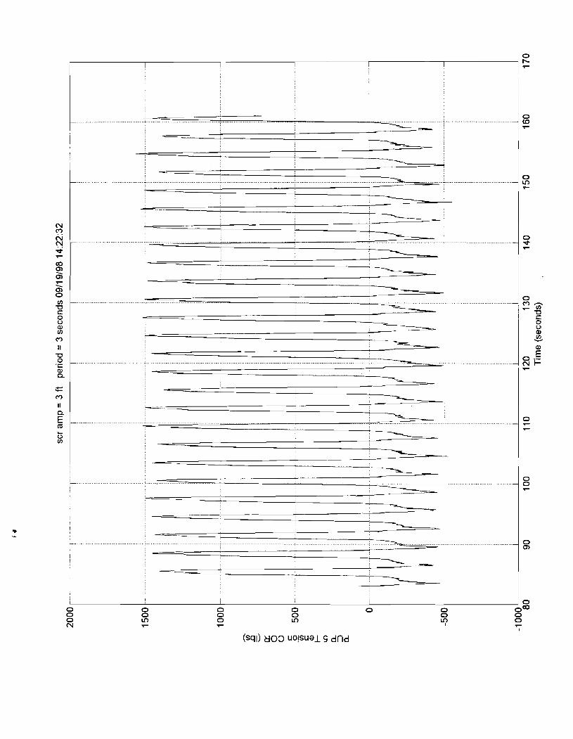

PUP 6 Bend lnplane COR (ft-lbs)


PUP 7 Bend lnplane COR (fl-lbs)

PUP 7 Bend Outplane COR (ft-lbs)


PLlP 8 Bend lnplane COR (ft-lbs) I I
I\, 2 0 rl, vl 2 vl 0
I P a"' cn 0 I I I I I I

PUP 8 Bend Outplane COR (ft-lbs) 2 2 2
03N W P CJl cn -A 03 (D 0 2 N
0 I I I I I I 1 I I
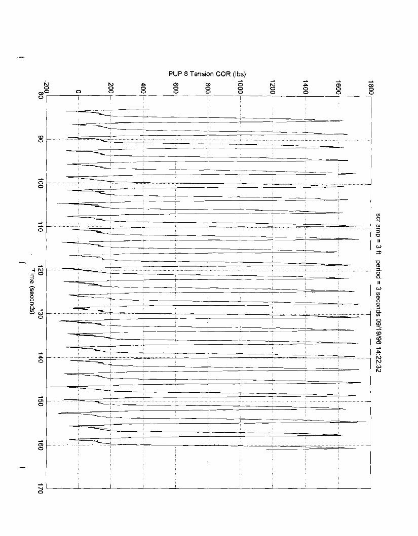
PUP 8 Tension COR (Ibs)

Pup 1 X Position (ft) I 3 -I 3
LJl 0 m 0 m go- I I I I
1


Pup 2 Y Position (ft)

Pup 3 X Position (ft)
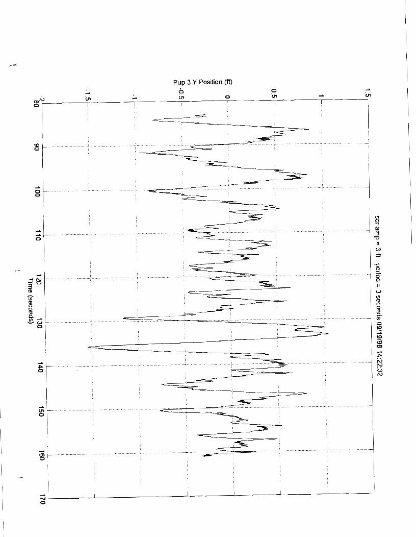

Pup 4 X Position (ft)


Pup 5 X Position (ft)


Pup 6 X Position (ft)


Pup 7 X Position (ft)

Pup 7 Y Position (ft)

Pup 8 X Position (ft)
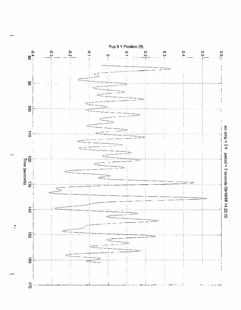


PUP 1 Bend lnplane COR (ft-lbs)

PUP 1 Bend Outplane COR (ft-lbs)

PUP 1 Tension COR (Ibs) --L 2 2

PUP 2 Bend lnplane COR (ft-lbs)


PUP 2 Tension COR (Ibs)


PUP 3 Bend Outplane COR (ft-lbs) 2 a N N
Am 0 m 0 W W cn 0

PUP 3 Tension COR (Ibs) h) N h) m A
m A 2
h) P m

PUP 4 Bend lnplane COR (ft-lbs) w rC, rC, 0 Cn 0

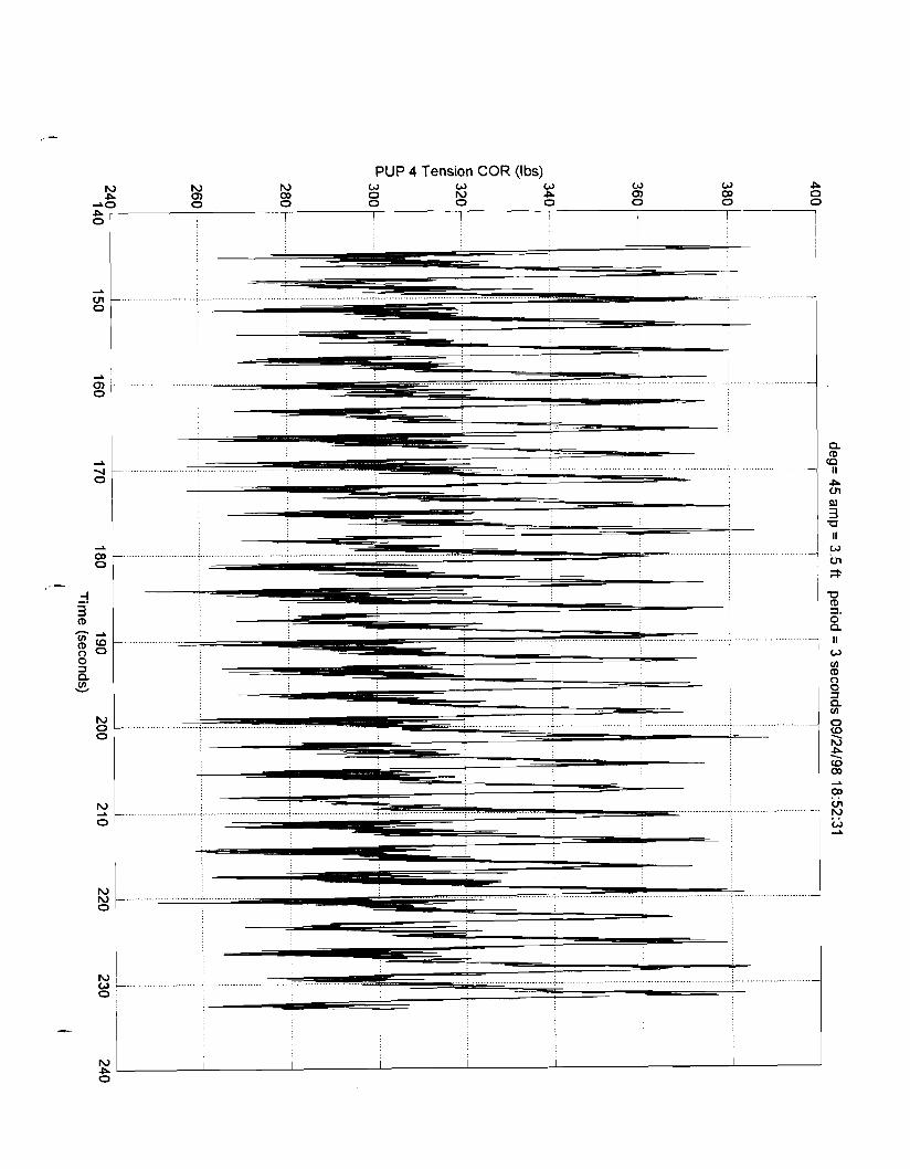
PUP 4 Tension COR (Ibs)
h ) i '&, i...... 0 ;
I
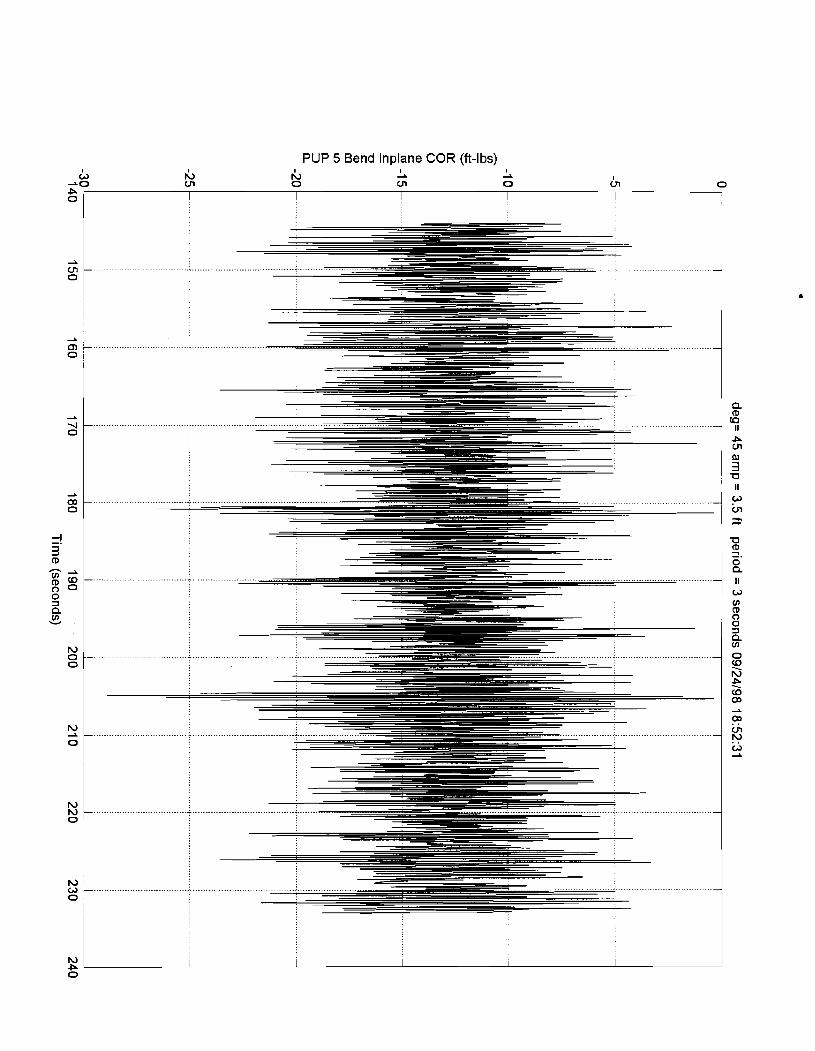
PUP 5 Bend lnplane COR (ft-lbs)

PUP 5 Bend Outplane COR (ft-lbs)
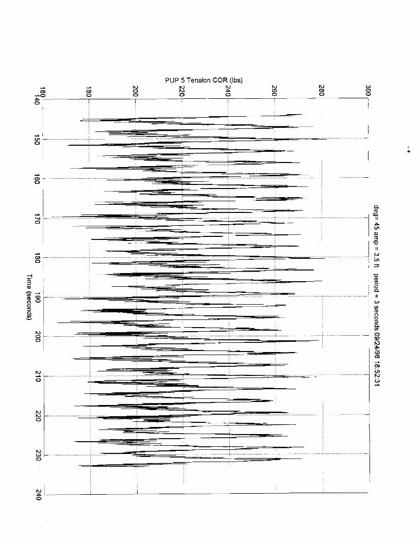
PUP 5 Tension COR (Ibs)

PUP 6 Bend lnplane COR (ft-lbs)

PUP 6 Bend Outplane COR (ft-lbs) r;, I
2 0 2 N o P
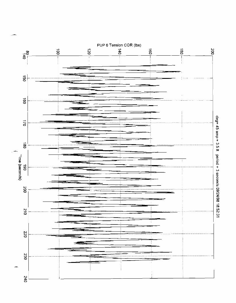
PUP 6 Tension COR (Ibs)
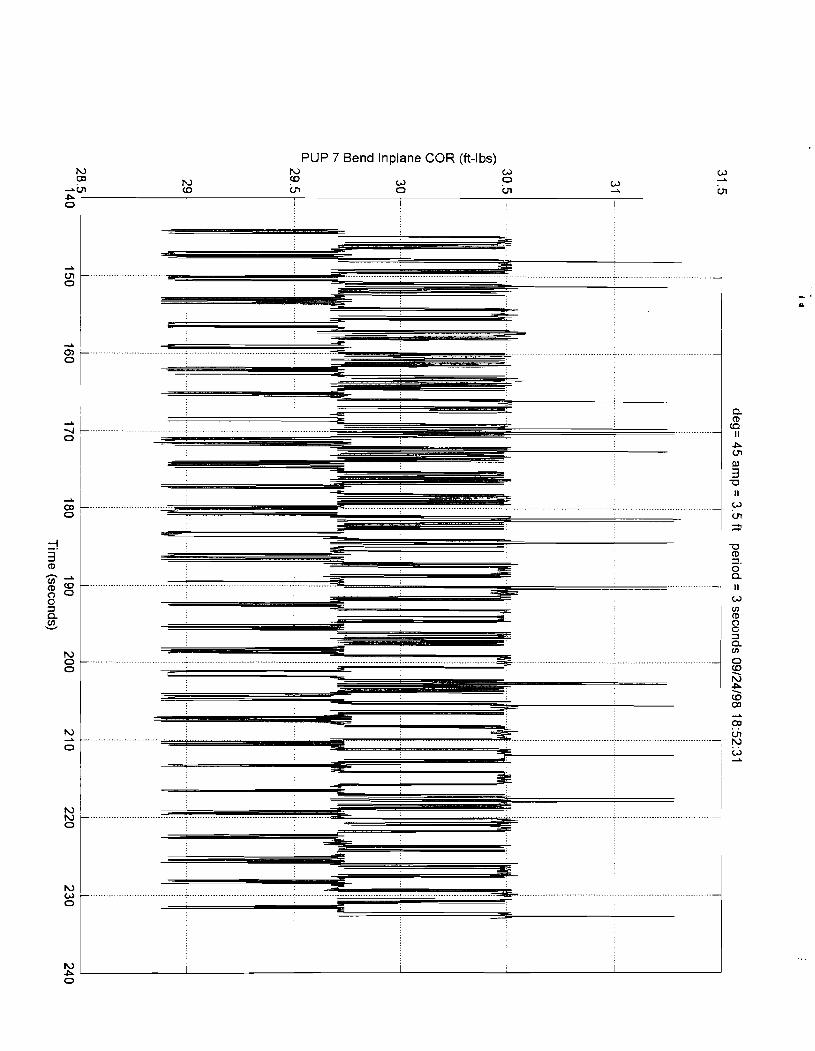
PUP 7 Bend lnplane COR (ft-lbs) N N 0 03 w 0
N 0 0 A
4i -in (D in 0 Ln P
Ln
o 1 I I 1 i I
0 0 1 a

PUP 7 Bend Outplane COR (ft-lbs) AA h) (3 a P
m a -J
I I 1 I I I I
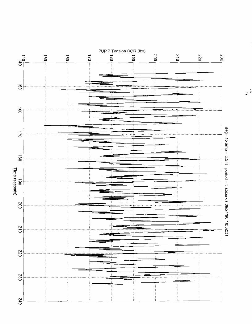
PUP 7 Tension COR (Ibs)

PUP 8 Bend lnplane COR (ft-lbs) r;, r;, r;, r;, r;, r;, r;, tL I I
I0 N I0 N r;, N Y N, : L A N N,
--\ CD 4 VI W m CD
0

PUP 8 Bend Outplane COR (ft-lbs) m VI VI VI m z VI
-w b 0, 4 05 (D a, !=" 2
!=" N
P 0 I I I I I I 1 1 I

PUP 8 Tension COR (Ibs)

Pup 1 X Position (ft)

Pup 1 Y Position (ft)

Pup 2 X Position (ft)

Pup 2 Y Position (ft)

Pup 3 X Position (ft)
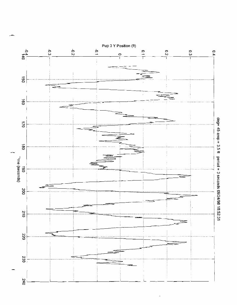
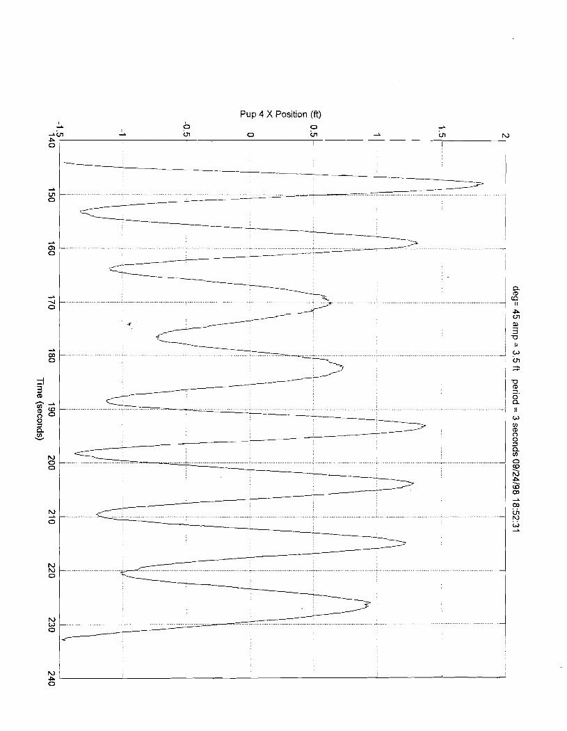
Pup 4 X Position (ft)

Pup 4 Y Position (ft)

Pup 5 X Position (ft)
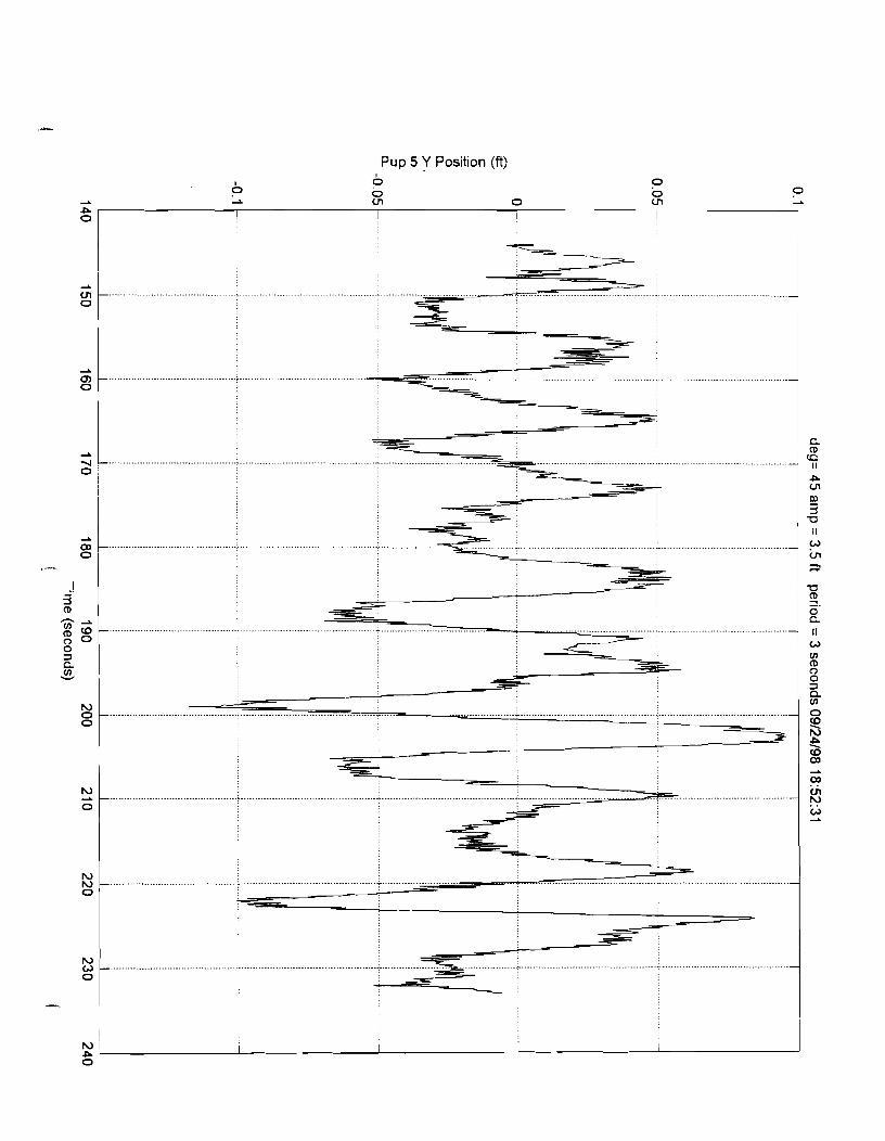
Pup 5 Y Position (ft)

Pup 6 X Position (ft)
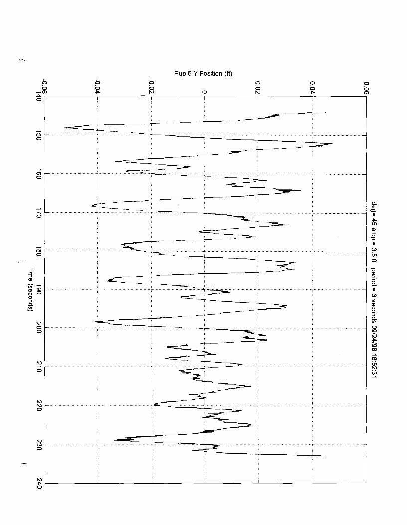
Pup 6 Y Position (ft)


Actuator Load (Ibs)
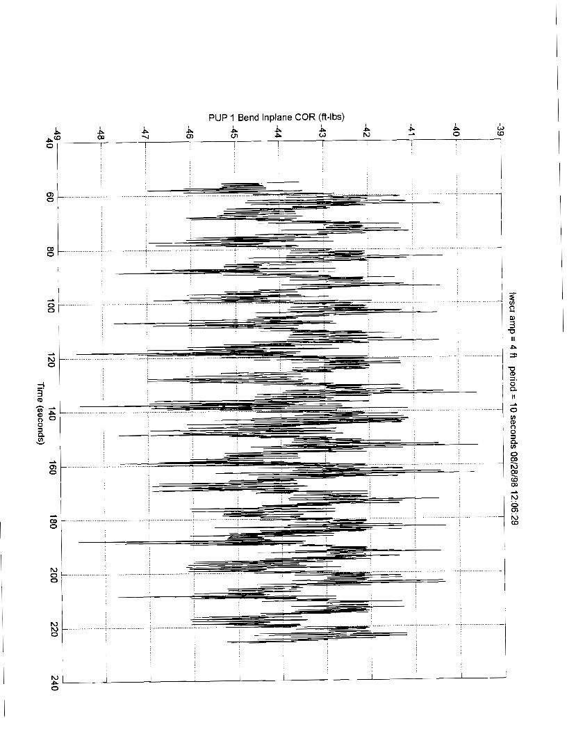
PUP 1 Bend lnplane COR (ft-lbs)

PUP 1 Bend Outplane COR (fi-lbs)
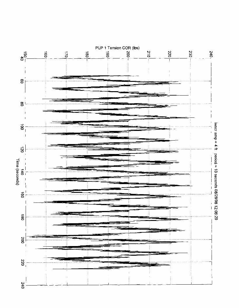
PLlP 1 Tension COR (Ibs)

PUP 2 Bend lnplane COR (ft-lbs)

PUP 2 Bend Outplane COR (ft-lbs)

PUP 2 Tension COR (Ibs)
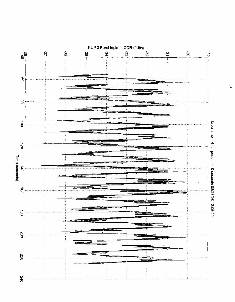
PUP 3 Bend lnplane COR (ft-lbs)

PUP 3 Bend Outplane COR (ft-lbs) 6,
A A
P A b rC1 0 ru P (3) 0 I I I I I I
I I
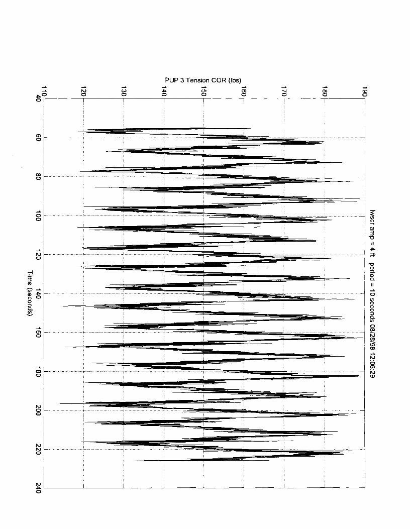
PUP 3 Tension COR (Ibs)
2 a L......
I

PUP 4 Bend lnplane COR (ft-lbs) ld L, G, ld I
2 ld b P 0 N 0 W b L
a"' 0 I I I I -

PUP 4 Bend Outplane COR (ft-lbs) I I 2 2 2
0 G( 0 wi 0
I I I
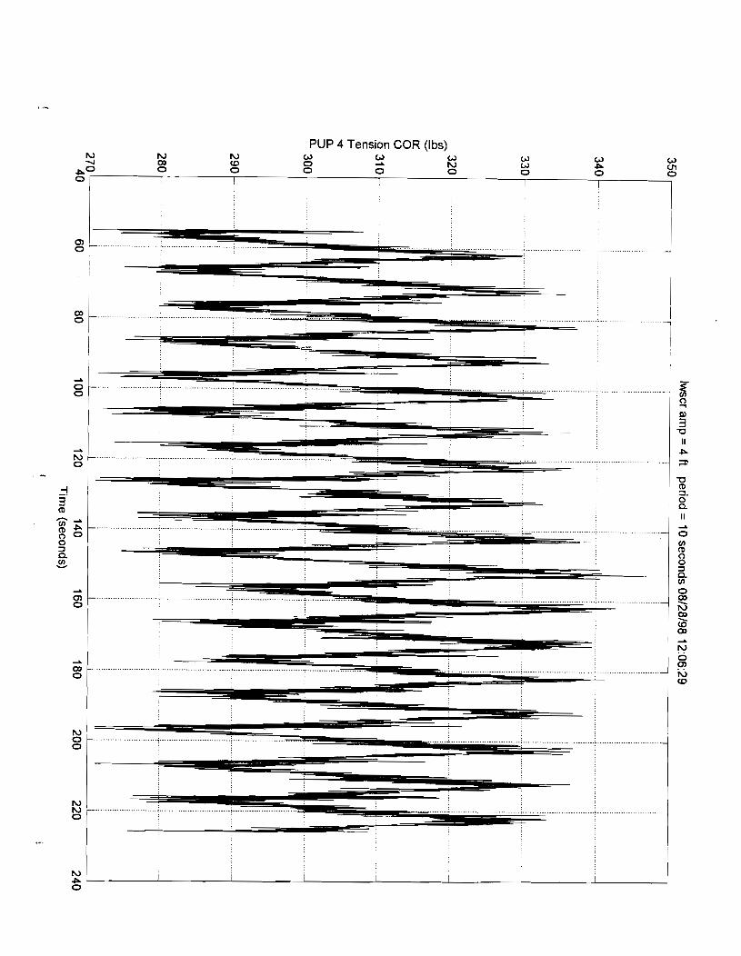
PUP 4 Tension COR (Ibs)
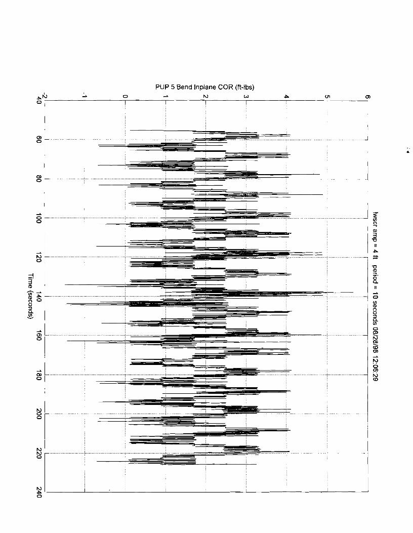
PUP 5 Bend lnplane COR (ft-lbs)
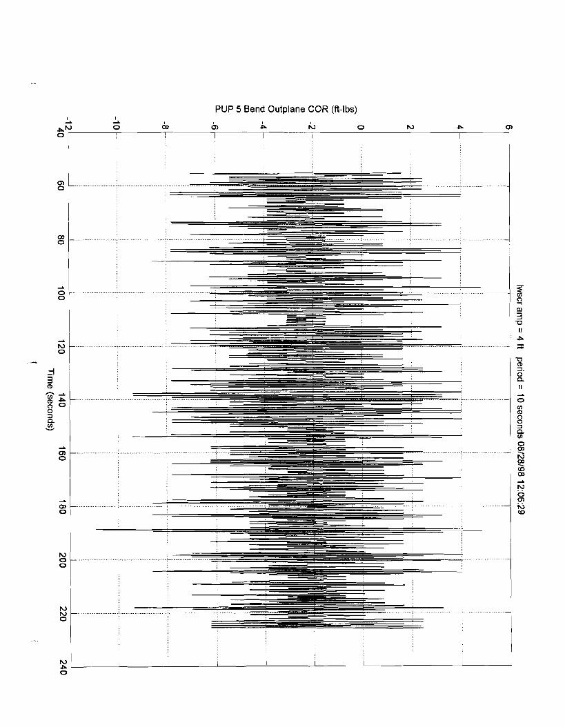
PUP 5 Bend Outplane COR (ft-lbs)

PUP 5 Tension COR (Ibs)
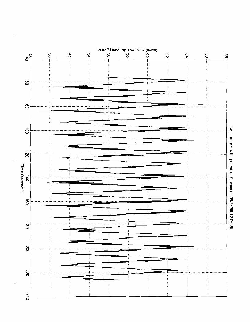
PUP 7 Bend lnplane COR (ft-lbs)

PUP 7 Bend Outplane COR (ft-lbs)

PUP 7 Tension COR (Ibs)
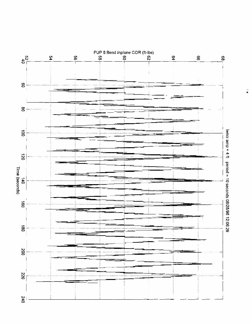
PUP 8 Bend lnplane COR (ft-lbs)

(sql-U) U 0 3 aueldln0 PuW 8 dfld

PUP 8 Tension COR (Ibs) P P P P P P P P ru W P U1 cn 4 0)
0 0 0 CD
PO 0 0 0 0 0 I I I I I ~
I

Pup 1 X Position (ft)
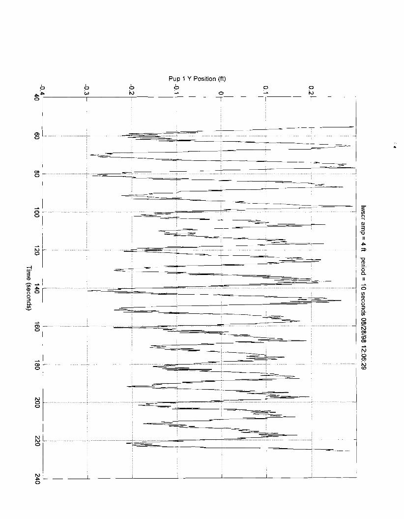
Pup 1 Y Position (ft)

Pup 2 X Position (ft) I
a=' b fL 0 lu P =' 0 I I I I I

Pup 2 Y Position (ft)

Pup 3 X Position (ft)
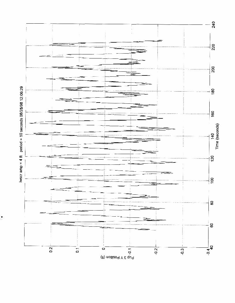


Pup 4 Y Position (ft)
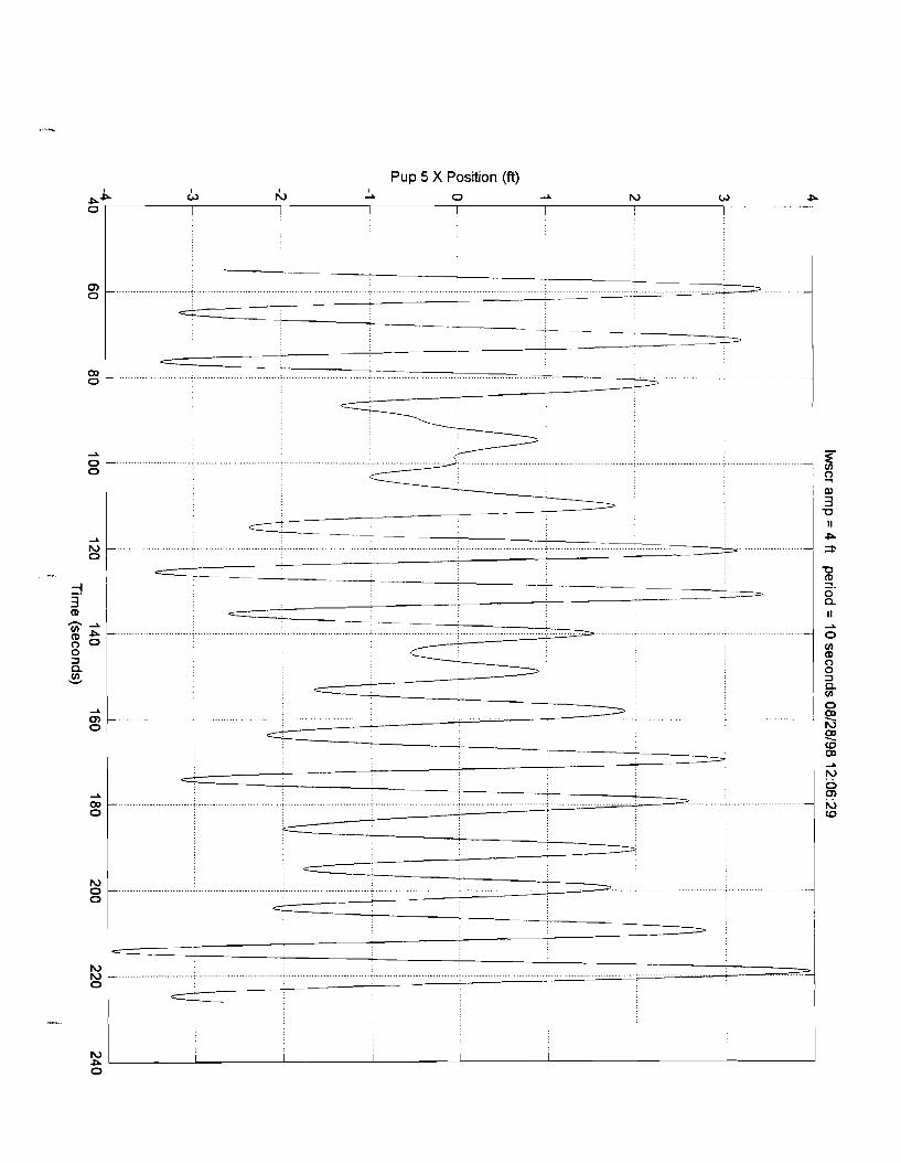
Pup 5 X Position (ft)


Pup 6 X Position (ft)

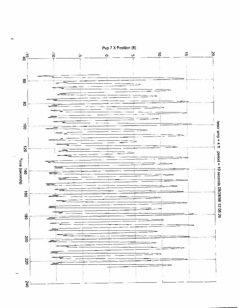
Pup 7 X Position (ft)

Pup 7 Y Position (ft)


Pup 8 Y Position (ft)


PUP 1 Bend Outplane COR (ft-lbs)

PUP 1 Bend lnplane COR (fi-lbs)

PUP 1 Tension COR (Ibs)

PUP 2 Bend lnplane COR (ft-lbs)
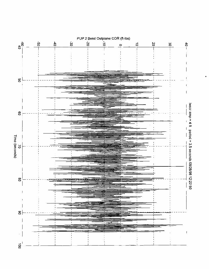
PUP 2 Bend Outplane COR (ft-lbs)

PUP 2 Tension COR (Ibs)

PUP 3 Bend lnplane COR (ft-lbs) tn Al Al b b La La N rC, I 2
PO M 0 M 0 M 0 rn 0 wl 0 I I I I I I I I
I I

PUP 3 Bend Outplane COR (ft-lbs) I
n b la rC, 3 3
3 0 0 0 0 0 0 0 0 0 0 10 W P Ln

PUP 3 Tension COR (Ibs)

PUP 4 Bend lnplane COR (ft-lbs) b, &I b ck, rC, I A
PO 0 0 0 0 0 0 0 i I I ! I
I

PUP 4 Bend Outplane COR (ft-lbs)

PUP 4 Tension COR (Ibs)

PUP 5 Bend lnplane COR (ft-lbs)

PUP 5 Bend Outplane COR (ft-lbs)

PUP 5 Tension COR (Ibs)

PUP 6 Bend lnplane COR (ft-lbs) A N W P ul
0 0 0 al
0 4
0 m
Po 0 0 0 1 I I I I I I I

PUP 6 Bend Outplane COR (ft-lbs)

PUP 6 Tension COR (Ibs)

PUP 7 Bend lnplane COR (ft-lbs)

PLlP 7 Bend Outplane COR (ft-lbs)

PUP 7 Tension COR (Ibs)
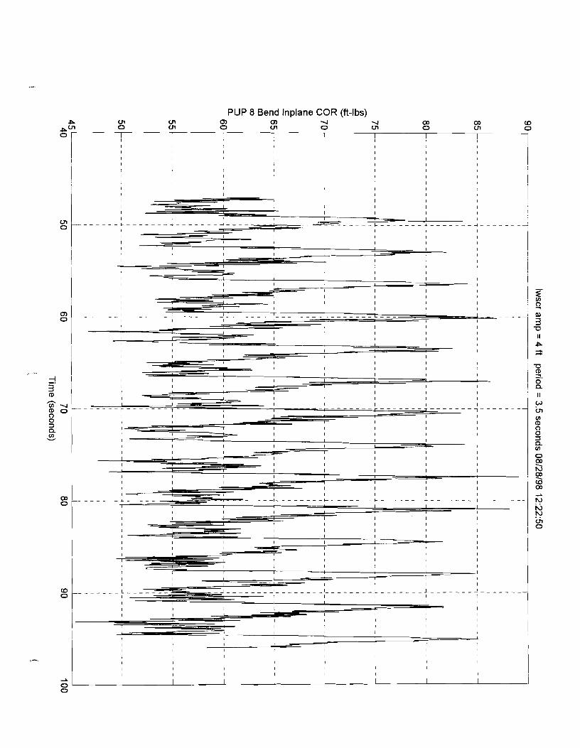
PLlP 8 Bend lnplane COR (ft-lbs) P 01 ul 0 0 4 4 0)
0 ul 0)
A‘'' 0 ul 0 ul 0 ul 0 I I 1 I I I I ~

PUP 8 Bend Outplane COR (ft-lbs)

PLlP 8 Tension COR (Ibs)

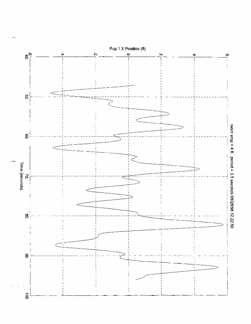
Pup 1 X Position (ft)


Pup 2 X Position (ft)
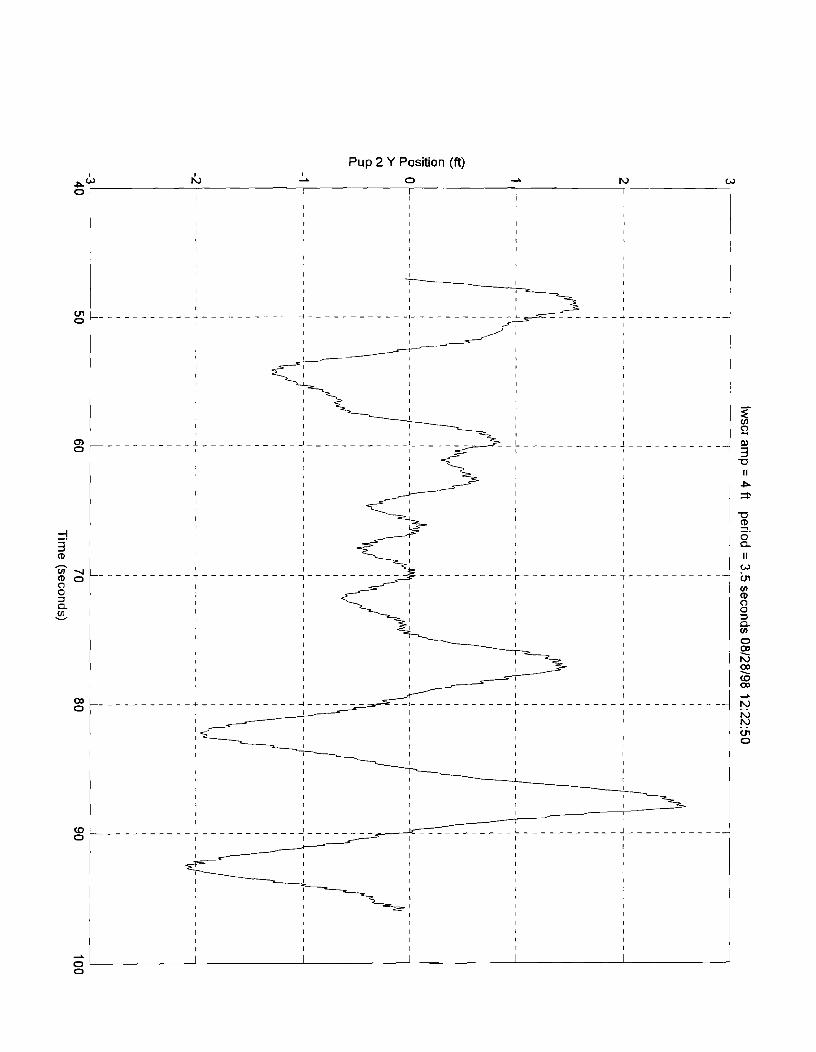

Pup 3 X Position (ft) I
PC" Ln b 0 P 0

Pup 3 Y Position (ft)


Pup 4 Y Position (ft)

Pup 5 X Position (ft)

Pup 5 Y Position (ft)

Pup 6 X Position (ft)

Pup 6 Y Position (ft)

Pup 7 X Position (ft)
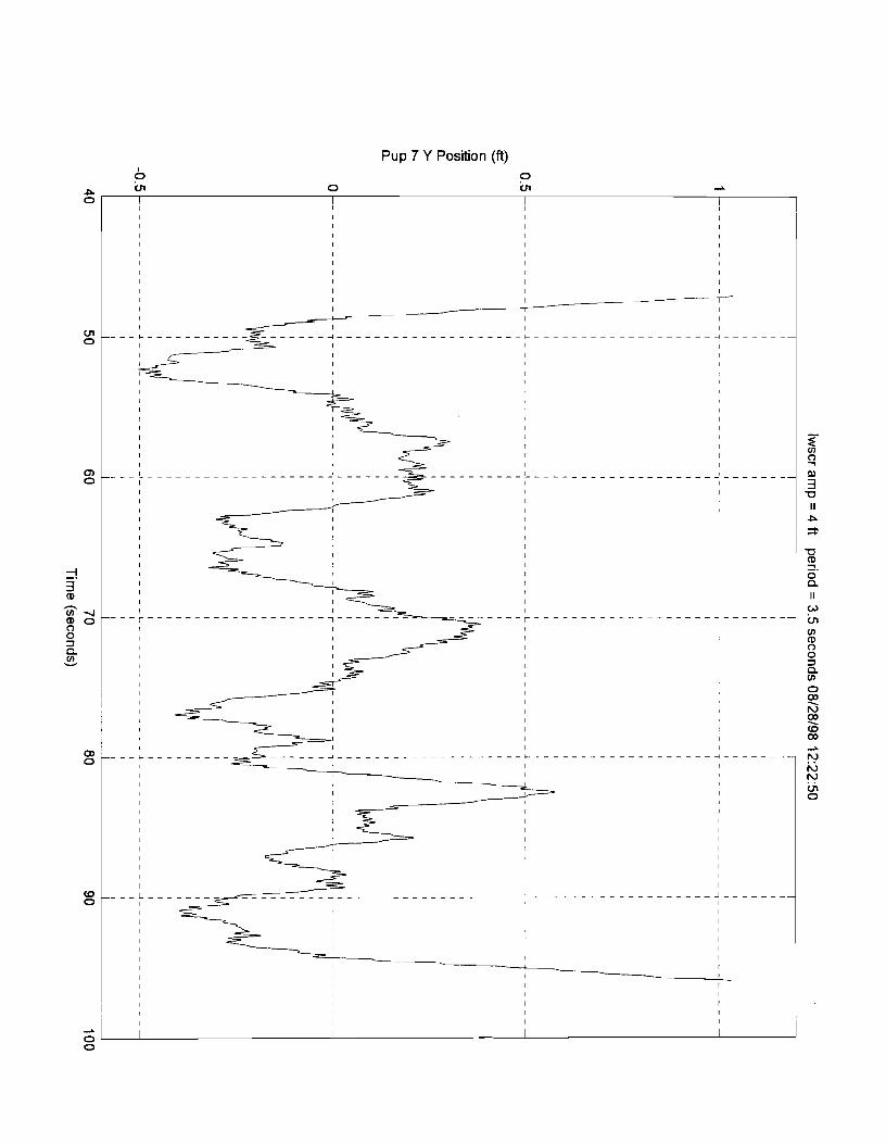
Pup 7 Y Position (ft) I
P rn 0 rn 2
P I I I I I
I I I I
I I
I I I
I I I
I I
I I I
I I I
I
I I I I I
I I I
I I I
I I
I I I -- I
I I
I I
I I I I I
- - - - C - - - - - - - - - - - - - - - - - - - - - - - - - - - C - - - - - - - - - - - - - - - - - - - 4 - - - - - - -
I I
I I
I I
I I
I
I
I I I
I I , I I
I I
I I
I I
I
I I
I I
I I
I I I I 3 I I I -3 I I I 7
I I . . . . . . . . . . . . . . . . . . . . . . . . I . . . . . . . . . . . . . . . . . . . . . . . . . . . . . . . . . . . . I I I s I I I
-0 I I
I I
I I II I I I P I I I
;F I I I I I I I 1 I -0 I I I s. I I I 0 I I I n I I I
I I II I
I I I -- - - r - - - - - - - - - - - - - - - - - - - r - - - - - - - - - - - - - - - - - - - 1-------- w Ln
I I I I V) I I
I I (D I I I -3 I I I 0 I I I 3 I I I n
V) I I I
I I I 0 I I I E? I 1 I I h)
I I I I I I s I
I I w I 2
- - - - - - - - - - - - - - - - d - - - - - - - -
I h) r\,
I I
I r\, I I VI
0 I I
I
I I
I I
I
I I
I
1 I I I
I I
I I I I I I I I
I I
I I
I I I I
I I I I
I I I I I I I I I
I
I I I I I I I I
~ I I I I ! I I I I
I I I


Scientific Marine Services, lnc. Escondido, CA 92029
December 1998 HCR JIP Riser Test Report Rev. 1.0
Appendix E
Calibration File Example

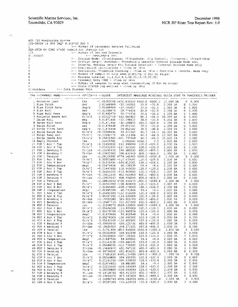
Scientific Marine Services, Inc. Escondido, CA 92029
December 1998 HCR J1P Riser Test Report Rev. 1.0
HCX JIP Monitoring System CIO-DASOB 14 300 IRQ7 8.319735 330 Y 1 <-- Number of Secondary Devices Following SER-STIM 64 COM2 57600 nodeid.txt chancdw.txt 12 6 <- - Numcer cf Derlved Channels 40.300000 < - - SampleRate ( H z ) S i-- Storaae Mode: iC)ontinuous; :Tlhreshold; (Oip Control; :Iinterval; (S) tart/Stop
i-- Sroraqe Lenqrh Imlnutesj: Threshoid h Operator Control Storage Mode only C < - - Interval Modulus (every Nth Process Interval1 - Interval Storage node only Y <-- Statlstlcal Calculations - IY!es or 1N)o N <-- Statistical Threshold Checking - (Yles or !N)o - Contlnue C Interval mode only 0 <-- Number of sample LO sklp when plotting (0 for no skips) 5 <-- Process interval 1 1 , 2 , 3 , 4 , 5 , 6 , 1 0 , 1 2 , 1 5 , 2 0 , 3 0 , E0)
N <- - Transmit Data COM2 - iY)es or (N)o 0 <- - Ncmber of samples to skip when transmitting (0 for no skips: Y <-- Store SYSTEM log entries - (Yles or 1N)o c:\hcrdata <-- Data Storage Path ................................................................................................................. CH# <-CHANNEL NAME-----------> <UNITS--> <-SLOPE INTERCEPT MAXSCALE MINSCALE DELTA STAT TX THRESHOLD TRIGGER
................................................................................................................. 1 Actuator Load lbs -2.65350000 5450.800000 5500.0 -5500.0 10.000 DA 0 0.000 2 Pipe Pitch de9 0.01488969 -30.145012 30.0 -30.0 2.000 DA 0 0.000 3 Pipe Pitch Rate deg/s 0.01488969 -30.145012 30.0 -30.0 2.300 DA 0 0.000 4 Pipe Roll deg -0.31495879 29.774636 30.0 -30.0 2.300 DA 0 0.000 5 Pipe Roll Rate deg/s -0.01495879 29.774636 30.0 -30.0 2.000 DA 0 0.000 6 Accuator Heave Acc ft/sA2 C.03322709 -100.065923 64.3 -64.3 10.000 DA 0 0.000 7 Barge Roll de9 0.01471440 -30.198833 30.0 -30.0 5.000 DA 0 0.000 8 Barge Roll Rate degis 0.01471440 -30.198833 100.0 -100.0 2.000 DA 0 0.000 9 Barqe Pitch deg -0.01476448 29.852142 30.0 -30.0 5.000 DA 0 0.000 10 Barge Pitch Rate deg/s -0.01476448 29.852142 30.0 -30.0 2.000 DA 0 0.000 11 Barge Surge Acc ft/sA2 -0.03368494 69.222543 64.3 -64.3 10.000 DA 0 0.000 12 Barge Sway Acc ft/sA2 -0.03390770 69.111356 64.3 -64.3 10.000 DA 0 0.000 13 Barge Heave Acc ft/s^2 0.03402365 -101.797669 64.3 -64.3 10.000 DA 0 0.000 14 Empty Channel 1 bs 1.00000000 0.000000 4096.0 0.0 2.000 DA 0 0.000 15 PUP 1 Acc Y Top ft/sh2 -0.05453500 112.390000 120.0 -12C.0 2.000 DA 0 0.300 16 PUP 1 Acc X Top fC/sA2 3.05331600 -111.920000 120.0 -120.3 2.000 DA 0 0.000 17 PUP 1 Bending X f:-lbs -0.19290430 394.480030 600.0 -600.0 2.000 DA 0 0.000 18 PUP 1 Bending Y ft-lbs -0.19452980 398.832440 600.0 -600.0 2.300 DA 0 0.000 19 PUP 1 Tension 1 bs -2.28124350 4779.162600 1000.0 -1000.0 2.000 DA 0 0.000 20 PUP 1 ACC Y Bot ft/sm2 0.05552800 -113.450000 120.0 -120.0 2.000 DA 0 0.000 21 PUP 1 ACC X Bot ft/sA2 0.05370400 -109.810000 120.0 -120.0 2.000 DA 0 0.000 22 PUP 1 Temperature degC -0.01679936 60.138535 59.4 -9.4 2.000DA 0 0.000 23 PUP 2 ACC Y Top ft/sA2 -0.05443600 110.940000 120.0 -120.0 2.000 DA 0 0.000 24 PUP 2 Acc X Top ft/sA2 0.05254200 -110.940000 120.0 -120.0 2.000 DA 0 0.000 25 PUP 2 Bending X ft-lbs -0.19612230 402.003900 600.0 -600.0 2.000 DA 0 0.000 26 PUP 2 Bending Y ft-lbs -0.19929140 408.936500 600.0 -600.0 2.000 DA 0 0.000 27 PUP 2 Tension 1 bs -2.28819440 4725.140470 1000.0 -1000.0 2.000 DA 0 0.000 28 PUP 2 Acc Y Bot f:/sA2 0.05340300 -108.840000 120.0 -120.0 2.000 DA 0 0.000 29 PUP 2 Acc X Bot ft/s^2 0.05355900 -108.270000 120.0 -120.0 2.000 DA 0 0.000 30 PUP 2 Temperature degC -0.01685304 60.733866 59.4 -9.4 2.000 DA 0 0.000 31 PUP 3 ACC Y Top ft/sA2 0.05483300 -112.050000 120.0 -120.0 2.000 DA 0 0.000 32 PUP 3 ACC X Top ft/sA2 0.05557200 -114.520000 120.0 -120.0 2.000 DA 0 0.000 33 PUP 3 Bending X ft-lbs -0.19100180 389.925700 600.0 -600.0 2.000 DA 0 0.000 34 PUP 3 Bending Y ft-lbs -0.19487710 401.057000 600.0 -600.0 2.000 DA 0 0.000 35 PUP 3 Tension lbs -2.21248070 4529.233500 1000.0 -1000.0 2.000 DA 0 0.000 36 PUP 3 Acc Y Bot ft/sn2 -0.05426500 111.930000 120.0 -120.0 2.000 DA 0 0.000 37 PUP 3 Acc X Bot ft/sA2 0.05379700 -110.560000 120.0 -120.0 2.000 DA 0 0.000 38 PUP 3 Temperature degC -0.01679936 59.802548 59.4 -9.4 2.000 DA 0 0.000 39 PUP 4 Acc Y Top ft/sA2 0.05278000 -108.480000 120.0 -120.0 2.000 DA 0 0.000 40 PUP 4 Acc X Top ft/sA2 0.05532100 -112.600000 120.0 -120.0 2.000 DA 0 0.000 41 PUP 4 Bending X ft-lbs -0.19956840 409.124700 600.0 -600.0 2.000 DA 0 0.000 42 PUP 4 Bending Y ft-lbs -0.19634320 399.371500 600.0 -600.0 '2.000 DA 0 0.000 43 PUP 4 Tension 1 bs -2.31351650 4813.546000 1000.0 -1000.0 2.000 DA 0 0.000 44 PUP 4 Acc Y Bot f</sA2 -0.05350500 109.510000 120.0 -120.0 2.000 DA 0 0.000 45 PUP 4 Acc X Bot ft/sA2 0.05260600 -107.100000 120.0 -120.0 2.000 DA 0 0.000 46 PUP 4 Temperature degC -0.01697506 59.609010 59.4 -9.4 2.000 DA 0 0.000 47 PUP 5 ACC Y Top ft/sA2 0.05349100 -109.660000 120.0 -120.0 2.000 DA 0 0.000 48 PUP 5 Acc X Top ft/sA2 0.05488100 -112.700000 120.0 -120.0 2.000 DA 0 0.000 49 PUP 5 Bending X ft-lbs -0.19660670 401.967100 600.0 -600.0 2.000 DA 0 0.000 50 PUP 5 Bending Y ft-lbs -0.19710000 402.816100 600.0 -600.0 2.000 DA 0 0.000 51 PUP 5 Tension lbs -2.37081810 4995.134000 1000.0 -1000.0 2.000 DA 0 0.000 52 PUP 5 Acc Y Bot ft/sA2 -0.05346800 109.450000 120.0 -120.0 2.000 DA 0 0.000 53 PUP 5 Acc X Bot ft/sA2 0.05261200 -105.020000 120.0 -120.0 2.000 DA 0 0.000 54 PUP 5 Temperature degC -0.01674603 59.881905 59.4 -9.4 2.000 DA 0 0.000 55 PUP 6 Acc Y Top ft/sA2 0.05230500 -106.240000 120.0 -120.0 2.000 DA 0 0.000 56 PUP 6 ACC X Top ft/sA2 0.05338800 -110.060000 120.0 -120.0 2.000 DA 0 0.000 57 PUP 6 Bending X ft-lbs -0.19728750 403.913200 600.0 -600.0 2.000 DA 0 0.000 58 PUP 6 Bending Y ft-lbs -0.19604970 403.143600 600.0 -600.0 2.000 DA 0 0.000 59 PUP 6 Tension lbs -2.34090740 4836.960000 1000.0 -1000.0 2.000 DA 0 0.000 60 PUP 6 Acc Y Bot ft/sA2 -0.05397300 112.420000 120.0 -120.0 2.000 DA 0 0.000

Scientific Marine Services, Inc. Escondido, CA 92029
December 1998 HCR JIP Riser Test Report Rev. 1.0
61 PUP 6 Act X Eot 62 PUP 6 Temperature 63 PUP 7 Acc Y Top 64 PUP 7 Failed X Top 65 PUP 7 Bending X 66 PUP 7 Bending Y 67 PUP 7 Tenslon 66 l3P 7 Acc Y Bot 69 PUP 7 Acc X Bot 70 PUP 7 Temperacure 71 PUP e ACC Y TOP 72 PUP 8 Acc X Top 73 PUP 8 Bending X 74 PUP 8 Bending Y 75 PUP 8 Tenslon 76 PUP 8 Acc Y Bot 77 PUP 8 Acc X Bot 78 PUP 8 Temperature -1 Actuator Heave Acc NOG -2 Barge Surge Acc NOG -3 Barqe Sway Acc NOG -4 Barqe Heave Acc NOG -5 PCP 1 Top Y F.cc COR -6 PUP 1 Top X Acc COR -7 PUP 1 Bot Y Acc COR -8 PUP 1 Bot X Acc COR -9 PUP 1 Static Y Acc
-iO PUP 1 Static X Acc -11 PUP 1 Rocation -12 PUP 1 Tilt Inplane -i3 PUP 1 Bend Inplane -14 PUP 1 Bend Outplane -15 PUP 2 Top Y Acc COR -16 PUP 2 Top X ACC C3R -1: PUP 2 Bot Y Acc COR -18 PUP 2 Bot X Acc COR -19 PUP 2 Static Y Acc -20 PUP 2 Statlc X Acc -21 PUP 2 Rotatlon -22 PUP 2 Tilt Inplane -23 PUP 2 Bend Inplane -24 PUP 2 Bend Outplane -25 PUP 3 Top Y Acc COR -26 PUP 3 Top X Acc COR -27 PUP 3 Bot Y Acc COR -28 PUP 3 Bot X Acc COR -29 PUP 3 Static Y Acc -30 PUP 3 Static X Acc -31 PUP 3 Rotation -32 PUP 3 Tilt Inplane -33 PUP 3 Bend Inplane -34 PUP 3 Bend Outplane -35 PUP 4 Top Y Acc COR -36 PUP 4 Top X Acc COR -37 PUP 4 Bot Y Acc COR -38 PUP 4 Bot X Acc COR -39 PUP 4 Static Y Acc -40 PUP 4 Static X Acc -41 PUP 4 Rotation -42 PUP 4 Tilt Inplane -43 PUP 4 Bend Inplane -44 PUP 4 Bend Outplane -45 PUP 5 Top Y Acc COR -46 PUP 5 Top X Acc COR -47 PUP 5 Bot Y Acc COR -48 PUP 5 Bot X Acc COR -49 PUP 5 Static Y Acc -50 PUP 5 Static X Acc -51 PUP 5 Rotation -52 PUP 5 Tilt Inplane -53 PUP 5 Bend Inplane -54 PUP 5 Bend Outplane -55 PUP 6 Top Y Acc COR -56 PUP 6 Top X Acc COR -57 PUP 6 Bot Y Acc COR -58 PUP 6 Bot X Acc COR -59 PUP 6 Static Y Acc -60 PUP 6 Static X Aoc -61 PUP 6 Rotation -6: PUP 6 Tilt Inplane
ft/sA2 degC ft/s*2 ft/sA2 ft-lbs ft-lbs lbs ft/S^2 Et/s'2 ceqC f:/sA2 fc/s-2 ft-lbs ft-lbs lbs ft/sA2 ft/sA2 degC Et/se2 Et/sA? Et/sA2 ft/s*2 Et/sA2 Et/SA? Et/sA2 ft/SA2 Et/sA2 Et/sA2 deg deq Et-lbs ft-lbs ft/s''2 ft/sA2 ft/sA2 ft/s02 ft/sA2 Et/sh2 deg deq ft-lbs ft-lbs ft/sA2 ft/s*2 Et/sh2 ft/sA2 Et/sA2 Et/sA? deq deq ft-lbs ft-lbs ft/sA2 ft/sA2 Et/sA2 ft/sA2 ft/s^2 ft/s*2 deg deq ft-lbs ft-lbs ft/sA2 ft/sA2 ft/sA2 Et/sA2 ft/sA2 Et/sA2 de q deq ft-lbs ft-lbs Et/SA2 Et/SA2 ft/sA2 Et/SA2 Et/sA2 ft/sA2 deg de g
: ,050 DA 2.000 DA 2.00C DA 2.000 DF. 2.000 DA 2.000 DA 2.030 LA
2.000 DA 2.000 D4 2.00C Di. 2.000 DA 2.000 DA 2.000 DF. 2.000 3A 2.000 DA 2.000 DA 2.000 DA
2.000 DA 10.000 DA 10.000 DA 10.000 DA 10.000 DA 1.000 DA 1.000 DA 1.000 DA 1.000 DA 1.000 DA 1.000 DA 1.000 DA 1.000 DA 2.000 DA 2.000 DA 1 .ooo DA 1.000 D?. 1.000 DA 1.000 3F. 1.000 3A 1.000 DA 1.000 DA 1.000 DA 2.000 DA 2.000 DA 1.000 DA 1.000 DA 1.000 DA 1.000 DA 1.000 DA 1.000 DA 1.000 DA 1.000 DA 2.000 DA 2.000 DA 1.000 DA 1.000 DA 1.000 DA 1.000 DA 1.000 DA 1.000 DA 1.000 DA 1.000 DA 2.000 CA 2.000 DA 1.000 DA 1.000 DA 1.000 DA 1.000 DA 1.000 DA 1.000 DA 1.000 DA 1.000 DA 2.000 DA 2.000 DA 1.000 DA 1.000 DA 1.00C DA 1.000 DA 1.000 DA 1.000 DA 1.000 DA 1.000 DA

Scientific Marine Services, Inc. Escondido, CA 92029
December 1998 HCR JIP Riser Test Report Rev. 1.0
PUP PUP PUP PUP PUP PUP
6 send Inplane 6 Bend Outpla~e 7 Top Y Acc COR 7 Top X Acc COR 7 Bot 1 Acc C3R ? Bot X Acc COR
-69 PLJP 7 Static Y Acc -70 PUP 7 Static X Acc -71 PUP 7 Rotatlon -72 PUP 7 Trlt Inplane -73 PUP 7 aend Inplane -74 P U P 7 Bend Outplane -75 PUP 8 Tcp Y Acc COR -76 ?UP 8 Top X ACE C3R -77 PLJP 8 Bot Y Acc COG -78 PUP a Bot X Acc COR -79 PUP 8 Static Y Acc -80 P U P 8 Static X Acc -81 PUP 8 Rctation - 8 2 P U P 8 Tilt Inpiane -83 PUP 8 Bend Inplane -94 PUP 8 Bend Outplane -85 Pipe Pitch C3R -96 Plpe Roil COR -e7 PUP 1 Static Rotation -88 PUP 1 Static Trlt Inplane -89 PUP 1 Bend Inplane :OR -30 P U P 1 Send Outplane COR -9i PUP 1 Tension COR -92 PUP 2 Static Rotation -93 PUP 2 Static Tilt Inplane -94 PUP 2 Bend Inplane COR -95 PUP 2 Bend Outplane COR -96 PUP 2 Tension COR -97 PUP 3 Static Rocation -98 PUP 3 Static Tilt Inplane -99 PUP 3 Send Inplane COR -100 PUP 3 Bend Outplane COR -101 PUP 3 Tension COR -102 PUP 4 Statrc Rotation -103 PUP 4 Statlc Tilt Inplane -104 PUP 4 Bend Inplane COR -105 PUP 4 Bend Outplane COR -106 PUP 4 Tension COR -107 PUP 5 Static Rotation -108 PUP 5 Static Tilt Inplane -109 PUP 5 Bend Inplane COG -110 PUP 5 Bend Outplane COR -111 PUP 5 Tension COR -112 PUP 6 Static Rotation -113 PUP 6 Static Tilt Inplane -114 PUP 6 Bend Inplane COR -115 P U P 6 Bend Outplane COR -116 PUP 6 Tension COR -117 PUP 7 Static Rotation -lie PUP 7 Statlc Tilt Inplane -119 PUP 7 Bend Inplane COR -120 P C P 7 Bend Outplane COR -121 PUP 7 Tension COR -122 PUP 8 Static Rotation -123 PUP 8 Static Tilt Inplane -124 PUP 8 Bend Inplane COR -125 PUP 8 Bend Outplane COR -126 PUP 8 Tension COR
ft-lbs ft-lbs ft/s": ft/s*2 ft/SA2 ft/sA2 ft/sA-' ft/SA? deg deg ft-~DS ft-lcs ft/s*2 ft/SA2 f:!SA2 f t s - n it/sa2 ft/sA2 deg deg ft-lbs fr-lbs de¶ 3eg deg deg ft-lbs ft-lbs 1bS deq deg ft-lbs ft-lbs lbs deg deg ft-lbs ft-15s 1bS deg deg ft-lbs ft-lbs 1 bs deg de¶ ft-lbS ft-lbs lbs deg deg ft-lbs ft-lbs lbs deg deg ft-lbs ft-lbs 1bS deg deg ft-lbs ft-lbS lbs
Notes : STAT has the following format: xy where
x is the processing interval to use D - Display Stats P - PROCINT Stats T - Test Stats
y is the statistic A - Average (mean1 R - Standard deviation X - maximum M - Minimum D - Double Amplitude Significant 14 X StdevJ S - Single Amplitude Significant (2 X Stdev)
i.e. PA is the Average over the PROCINT processing interval
2.000 DA 2.000 DA 1.000 DA 1.000 DA 1.000 DA 1.000 DA 1 .SO0 DA 1.000 DA 1.000 DA 1.000 3A 2.000 DA 2.000 DA 1.000 DA 1.000 DA 1.300 DA 1.000 DA 1.000 DA 1.000 DA 1.000 DA 1.000 LA 2.002 DA 2.300 DA 2.000 DA 2.000 3A i.OOO DP. 1.000 DA 1 .COO DA 2.000 DA 2.000 DA 1.000 DA 1 .OOO DA 2.000 DA 2.000 DA 2.000 DA 1.000 DA 1.000 DA 2.000 DA 2.000 DA 2.000 DA 1 .OOO DA 1 .OOO DA 2.000 DA 2.000 DA 2.000 DA 1.000 DA 1.000 DA 2.000 DA 2.000 DA 2.000 DA 1.000 DA 1.000 DA 2.000 DA 2.000 DA 2.000 DA 1.000 DA 1.000 DA 2.000 DA 2.000 DA 2.000 DA 1.000 DA 1 .OOO DA 2.000 DA 2.000 DA 2.000 DA

Scientific Marine Services, Inc. Escondido, CA 92029
THRESHOLD i s used f o r T h r e s h o l d S t o r a q e Mode and S t a t ~ s t i c a l T h r e s h o l d Check ing . When u s l n g T h r e s n o l d S t o r a g e Mode, any c h a n n e l t h a t s h c u l d be compared a g a i n s t t h e THRESHCLD needs t o be Ecl lowed by t h e l e t t e r 'T'. When u s i n g S t a t i s t i c a l T h r e s h o l d Checking, any c h a n n e l ' s statistics t h a t s h o u l d be compared a q a i n s r t h e THRESHCLD needs t o be f o l l o w e d by a l e t t e r c o r r e s p o n d i n g t o t h e d e s i r e d s t a t i s t i c (A,R,X,H,D and S ) . When more t h a n one c h a n n e l I n s e l e c z e d , any one c h a n n e l above t h e THRESHOLD w i l l c a u s e a l l c h a n n e l s t o be s a v e d .
December 1998 HCR JIP Riser Test Report Rev. 1.0

Scientific Marine Services, Inc. Escondido, CA 92029
Appendix F
Constants File Example
December 1998 HCR JIP Riser Test Report Rev. 1.0
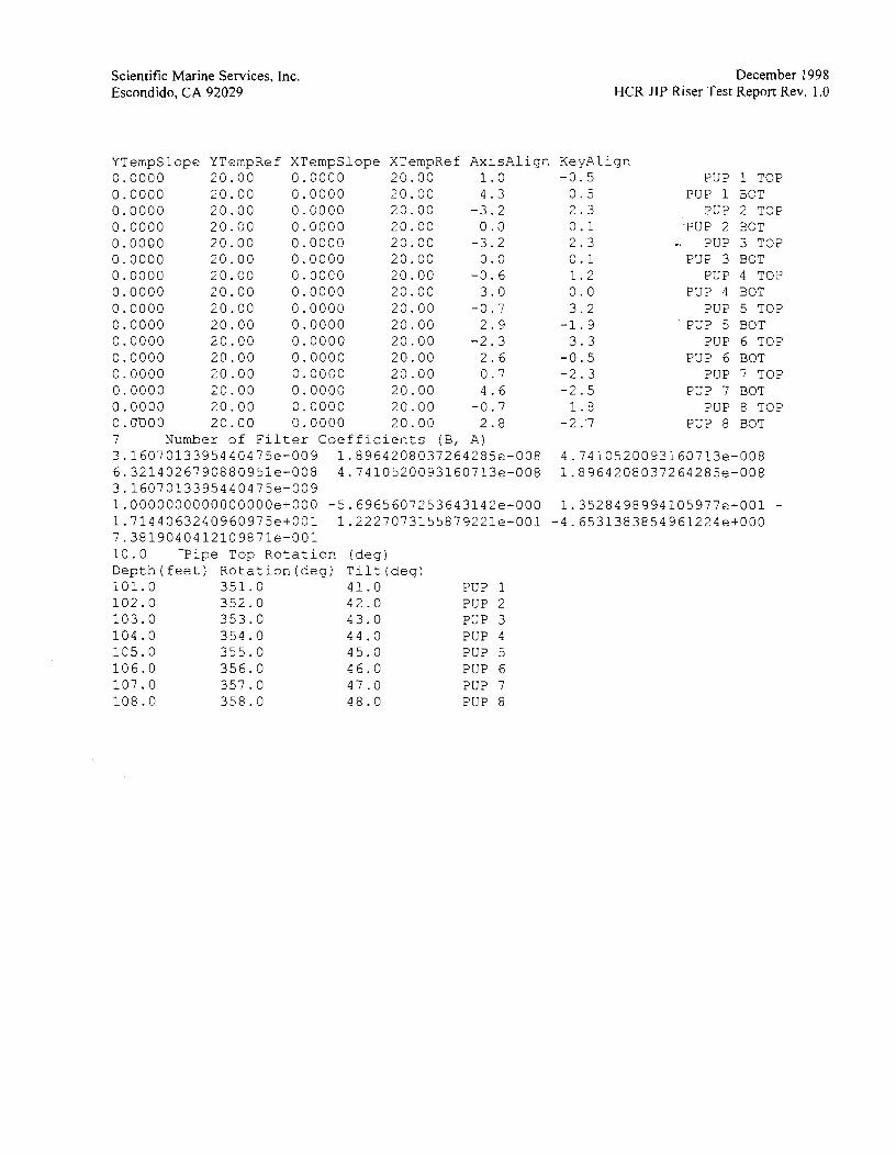
Scientific Marine Services, Inc. Escondido, CA 92029
December 1998 HCR JIP Riser Test Report Rev. 1.0
YTempSlope YTempRef XTempSlope XTempRef AxisAlign KeyAlign 0.0000 20.00 0.0000 20.00 1.0 -0.5 PUP 1 TOP 0.0000 20.00 0.0000 20.30 4.3 0.5 PUP 1 BOT 0.0000 20.00 0.0000 20.00 -3.2 2.3 PUP 2 TOP 0.0000 20.00 0.0000 20.00 0.0 0.1 'PUP 2 EOT 0.0000 20.00 0.0000 20.00 -3.2 2.3 -. PUP 3 TOP 0.0000 20.00 0.0000 20.00 0.0 0.1 PUP 3 BOT 0.0000 20.00 0.0000 20.00 -0.6 1.2 PUP 4 TOP 0.0000 20.00 0.0000 20.00 3.0 0.0 PUP 4 BOT 0.0000 20.00 0.0000 20.00 -0.7 3.2 PUP 5 TOP 0.0000 20.00 0.0000 20.00 2.9 -1.9 ' PUP 5 BOT 0.0000 20.00 0.0000 20.00 -2.3 3.3 PUP 6 TOP 0,0000 20.00 0.0000 20.00 2.6 -0.5 PUP 6 BOT 0.0000 20.00 0.0000 20.00 0.7 -2.3 PUP 7 TOP 0.0000 20.00 0.0000 20.00 4.6 -2.5 PUP 7 BOT 0.0000 20.00 0.0000 20.00 -0.7 1.8 PUP 8 TOP 0. ~ 0 0 20.00 0.0000 20.00 2.8 -2 .'7 PUP 8 BOT 7 Number of Filter Coefficients (B, A) 3.1607013395440475e-009 1.8964208037264285e-008 4.7410520093160713e-008 6.3214026790880951e-008 4.7410520093160713e-008 1.8964208037264285e-008 3.1607013395440475e-009 1.0000000000000000e+000 -5.6965607253643142e+000 1.3528498994105977e+001 - 1.7144063240960975e+001 1.2227073155879221e+OOl - 4 . 6 5 3 1 3 8 3 8 5 4 9 6 1 2 2 4 e + 0 0 0 7.3819040412109871e-001 10.0 -Pipe Top Rotation (deg) Depth (feet) Rotation (deg) Tilt (deg) 101.0 351.0 41.0 PUP 1 102.0 352.0 42.0 PUP 2 103.0 353.0 43.0 PUP 3 104.0 354.0 44.0 PUP 4 105.0 355.0 45.0 PUP 5 106.0 356.0 46.0 PUP 6 107.0 357.0 47 .O PUP 7 108.0 358.0 48.0 PUP 8