highway linear referencing udot 07-20 - the official website of
TRANSCRIPT

Highway Linear Referencing UDOT 07-20 Effective: August 1, 1997 Revised: March 31, 2016 Purpose
To establish a standard method of describing the location of events and features along Utah Department of Transportation (Department) roadways. It establishes guidelines when referencing locations or exchanging data for all classes of roads within the State of Utah. A common, standard linear location reference system is required in order to facilitate the exchange of data across different groups, systems, and functional areas in the Department.
Policy
1. The standard method for linear location referencing within the Department is the route and mile point (MP) method. The method is also known as accumulated mileage. This means that the location of any given event or feature is described by naming the route and stating the linear distance in miles from the beginning of the route to the event or feature in question.
2. The official description of the transportation system, including descriptions
of individual routes, length of routes, and location of major features along each route, is the Highway Referencing section, published on the Department website under Program Development Division.
3. Mileposts are placed in the field at each whole mile according to guidance
provided in the Manual on Uniform Traffic Control Devices (MUTCD). Although every effort is made to place mileposts at the exact location indicated by the MP, a milepost may be placed as far as 50 feet from the true MP. A milepost is omitted if it cannot be placed within 50 feet of the true MP. Mileposts do not define the MP. Rather, the MP dictates the location of mileposts. A mile post is not placed at the end of a route unless by coincidence the end of the route falls at an exact whole mile.
4. Mileposts are placed on all state routes, on the right side of the road in the
primary direction. Mileposts are placed on both sides of Interstate routes. Other divided roads or very wide undivided roads may also have mileposts placed on both sides of the road at the discretion of the Region Director and in cooperation with the Highway Reference Manager.

5. Milepoints increase in the primary direction of the route. The primary direction is either south to north or west to east based on the nominal direction of the route. Some segments of a particular route may follow a bearing that is contrary to the route’s nominal direction. MP zero is always at either the southern terminus or western terminus of the route.
6. The primary direction is the basis for the linear location of any event or
feature along the route. The location of an event occurs on the negative side of a divided roadway is determined by the location of the point directly opposite, on the primary side of the roadway. Locations of events or features on the negative side can generally be determined by measuring from a milepost on the negative side because mileposts are placed on the negative side directly opposite the corresponding post on the primary side. Refer to Procedures, Item 2.
7. Any change that affects the length of a route such as realignment due to a
project, or Commission action such as Jurisdictional Transfer or Highway Resolutions, the response to the change will follow the Department’s policy and the following “Remileposting Decision Matrix.”


8. The Department Geographic Information Systems (GIS) staff in concert with the Highway Referencing information will manage and maintain a spatial representation of the linear referencing system.
Background
Utah highways have been referenced through the use of mileposts since the 1970s. The numbers on the posts were originally intended to represent the exact mileage or accumulated distance from the beginning of the route to that particular post. Changes in highway alignment, length, ownership, or route number caused posts to be moved or required equations to be used to compensate for the impact of those changes. Movement of posts or usage of equations created confusion since the post numbers no longer represented the true accumulated mileage. Efforts in the mid-1990s to maintain addressing systems to keep track of accumulated mileage in the office without requiring posts in the field to be moved resulted in additional confusion in many cases. An effort was initiated to align field location of posts with their true accumulated mileage in 2002. The Department in 2009 formalized a spatial representation of its linear referencing system in a GIS format. Those efforts have resulted in the ability of spatially focused applications to utilize and analyze the Department’s LRS to visualize, plot, and segment features for representation. The Department will continue to manage a spatial representation of its LRS with the goal of matching the highway reference information as closely as possible or within 50 feet.
Definitions Accumulated Mileage
Cumulative distance from the beginning of a highway to a location on the highway recorded in miles.
Certain routes in Utah have a temporary end at one point and begin again at another point. Some of these routes (US numbered and Interstate) are defined by national policy as concurrent (overlapping) with one or more other routes. Other State routes are considered discontinuous. The difference is that on a concurrent route, distance measurement continues over the overlapping portion while on a discontinuous route, distance measurement is suspended at the temporary end and then resumes at the point where the route begins again. Refer to Discontinuous Route.
Address
Refer to Roadway Identifier

AGRC The Utah Automated Geographic Reference Center
Auxiliary Lane Lane that connects an on-ramp with the next interchange off ramp. Calibration A process used during the maintenance of a route (spatial) that maintains measures throughout the network. Calibration points are used to verify/maintain measures throughout the LRS network so that features and events fall onto the system (geographically) within their specified tolerance.
Collector-Distributor A set of freeway lanes physically separated from the main thru lanes for the purpose of eliminating weaving and ingress or egress movements on the main thru lanes while still satisfying the need for access to and from the freeway. Collector-distributor roads may be provided within a single interchange, through two adjacent interchanges, or continuously through several interchanges of a freeway segment. Continuous collector-distributor roads are similar to continuous frontage roads except that access to abutting property is not permitted.
Collector-Distributor roadways will always be associated with a single interchange. Diagrams created in the Program Development Division are the official source for all Collector-Distributor numbering. Example: The southbound Collector-Distributor roadway on I-15 serving the 1300 South and SR-201 interchanges would be designated as 0015NC30555. This roadway designation indicates:
a. Primary association with Route 0015
b. N is the direction indicator
c. The Roadway Type (C) is a collector-distributor
d. The Collector-Distributor is associated with Interchange 305 e. The Roadway Number is 55 as designated on the diagram of
ramps and Collector-Distributor for the 1300 South interchange.

Complex Intersections There are instances where complex intersections (refer to diagrams below) are handled differently in terms of their respective highway referencing information and the geographical (GIS) representation of the route or routes within an intersection. Roundabouts, Diverging Diamond Interchanges (DDI), Continuous Flow Intersections (CFI), Thru Turn, and other complex intersections often make it difficult to manage either the highway referencing or spatial representation of these instances. There are circumstances where a simplified approach must be taken to facilitate required functionalities for locating features along routes
State Route 175 is an example of how both the highway reference information and spatial representation of a roundabout is treated. Because of its complexity and route definition, only the positive direction is measured and cartographically represented.

The Interstate 15 and State Route 145 Diverging Diamond Interchange (DDI) is another complex intersection of routes that requires special circumstances from a highway referencing information and spatial representation process. The positive direction centerline method is used to manage this scenario due to its complexity and route definition.
The above Fed-Aid roundabout with a centerline measured in positive direction is another example of a complex intersection.
The Continuous Flow Intersection (CFI) at 5400 South and Redwood Road is one more example of a complex intersection designed to improve west-east traffic flow and to reduce left turn wait times especially during rush hour traffic.

The 12300 South in Draper is a ThrU Turn intersection designed to improve traffic flow at the main intersection by redirecting left turn through signallized u-turn locations and providing additional green time for the main intersection.
Concurrent/Overlapping Routes Certain routes in Utah (US numbered and Interstate) are defined by national policy as concurrent (overlapping) with one or more other routes. The purpose of the national policy is to maintain continuity in route numbering across state lines on certain routes of national importance as an aid to nationwide travel. Distance measurement continues over the overlapping portion on a concurrent route. Locations in the central database will be associated with one and only one route in cases where two or more routes run concurrently over a portion of their length. A list of all Concurrent/Overlapping Routes in Utah can be found at the Department Website under the Program Development Division Highway Referencing Section at this link: http://www.udot.utah.gov/main/f?p=100:pg:0:::1:T,V:814,
Continuity in distance numbering with concurrent/overlapped routes will be established for only one of the routes; the controlling route indicated in the list of Concurrent/Overlapping Routes. The first milepost beyond the overlap indicates the total distance traveled on the route so that a motorist may have a means of correlating his travel distance between mileposts and that shown on his odometer on the route without milepost continuity.
Direction
Direction is a route attribute and is designated as P for the positive direction (generally South to North or West to East) and N for the negative direction (generally North to South or East to West).

P – The northbound or eastbound lanes on divided roadways or either side of the road on a bidirectional roadway. All Ramps and Collectors leaving the Positive Direction lanes. All Zones and Roundabouts. “P” is the default value for direction.
N – The southbound or westbound lanes on divided roadways All Ramps and Collectors leaving the Negative Direction lanes.
Discontinuous Routes Routes that come to a temporary end at one point and then begin again at another point are referred to as “discontinuous” routes. A route is discontinuous when the distance at the beginning of the second section is the distance at the end of the first section plus .001, and so on. The distance is incremented by 0.001 miles in order to create a unique location in the Location Referencing System Database. A list of Discontinuous Routes in Utah can be found at the Department Web site under the Program Development Division Highway Referencing Section. Refer to http://www.udot.utah.gov/main/f?p=100:pg:0:::1:T,V:814, Distance Increments\Decrements Accumulated distances increase or decrease relative to the route’s positive direction. The accumulated distance increases when traveling in the positive direction and the accumulated distance decreases. When traveling in the negative direction.
Divided Routes Divided routes are routes on which the lanes for one direction are physically separated from the lanes for the opposite direction, usually by being contained on separate roadway prisms. Roadway separations that constitute a divided highway can consist of both horizontal and vertical separations. The route’s primary direction is used for linear location referencing purposes even though the length of roadway in the negative direction may be different. Examples of routes defined as divided routes are interstates and expressways. A list of all Divided Routes in Utah can be found at the Department Website under the Program Development Division Highway Referencing Section: Refer to http://www.udot.utah.gov/main/f?p=100:pg:0:::1:T,V:814,

Floating Ramps
Unique GIS dataset maintained to represent ramps on Utah’s Highway System. This dataset is necessary as it represents a more accurate mileage reflected in Highway Referencing. This GIS dataset differs from what is being displayed in UTRANS (Refer to Definitions), which is more of a cartographic representation of each ramp on the system. The ramp mileage is collected from gore to end of curve. Refer to the below diagram.
Highway Location Reference Method
The primary objective of the highway linear location reference method is two fold. First, to provide a means for designating and recording the geographic positions of specific locations on a roadway. Second, to use the designations as a key to stored information about the locations. The system must be easy to use to accommodate various levels of technical skills. Three elements common to all location reference methods are:
a. Identification of a known point b. A measurement from the known point c. A direction of measurement

A highway location reference method is a set of procedures used in the field to identify the location of any point. Highway Location Reference System A highway location reference system is a set of office and field procedures that includes one or more highway location reference methods. The method is a way to identify a specific location with respect to a known point. The system is seen as the procedures that relate all locations to each other and includes techniques for storing, maintaining, and retrieving location information. Interchange A system of interconnecting roadways in conjunction with one or more grade separations that provides for the movement of traffic between two or more roadways or highways on different levels. An interchange will be identified using an interchange number (Refer to the Definition Roadway Identifier). The interchange number will be a 3- digit character-type field using numeric characters. Interchanges are associated most often with Interstate routes but are also associated with expressways and other principal arterials. The Interchange Number generally follows MUTCD guidelines for numbering of interchanges. Traffic and Safety has the responsibility to create and maintain the interchange numbers. The interchange by definition will be associated with the route of higher functional classification. The route with the lowest number will control if the routes meeting at the interchange are of the same functional classification, Interchange Diagrams in Utah can be found at the Department Website under the Program Development Division Highway Referencing Section. Refer to http://www.udot.utah.gov/main/f?p=100:pg:0::::V,T:,4299 Example 1: A ramp at the interchange of I-15 and I-215 in Murray will be designated as 0015PR302xx because the functional classes are the same, 15 is a lower number than 215 and the interchange number on I-15 is 302. The Event Date field parameter would precede the Route Number to provide the full Roadway Identifier data.
Example 2: A ramp at the interchange of US-40 (a principal arterial) and SR-248 (a minor arterial) east of Park City will be designated as 0040PR004xx because US-40 is of a higher functional classification than SR-248 and the interchange number on US-40 is 004. The Event Date field would precede the Route Number to provide the full Roadway Identifier data. Refer to Ramp Nomenclature for interchange ramp identification.

Linear Location Referencing Is an identification of locations of events or features along a linear, one-dimensional entity such as a road, railway, or pipeline. Location Notation Format: xxx.yyy, the xxx being the total whole miles and the yyy, thousandths of a mile. Measuring Measuring distance on roadways, ramps and collector or distributors will be done on the outside shoulder or the outside edge of the outside lane. The outside lane may be used for measuring if a shoulder does not exist or other conditions require it. Measuring will be done in the primary direction for mainline. Ramps and Collector or Distributors will be measured in the direction of travel, beginning at the start of the ramp or collector or distributor. Results will be recorded in miles accurate to three decimal places. Note: Deceleration lanes for exits are considered part of the mainline.
Milepoint (MP) Synonymous with Accumulated Mileage.
Milepost
A sign placed in the field at an exact whole mile. The number on the sign represents the exact MP (accumulated mileage) within 50 feet at that point.
Negative Direction (N) The negative direction (N) is the direction of travel where the accumulated distance decreases.
Nominal Direction The general direction a route follows from its beginning to its end, either south to north or west to east. A route begins at its nominal southern or western terminus and ends at its nominal northern or eastern terminus. Some segments of a route (sometimes long segments) may follow a bearing that is contrary to the route’s nominal direction. For example, I-215 is a south to north route, although from its beginning near Parley’s Canyon it follows a southerly, then westerly bearing extending for nearly half its length.
Positive Direction (P)
The positive direction (P) is the direction of travel where the accumulated distance increases.
Primary Direction (P) Same as positive direction.

Ramp Is a turning roadway that connects two or more legs at an interchange. The
components of a ramp are a terminal at each leg and a connecting road, usually with some curvature, and on a grade. A ramp may connect a route to a cross street, to another route, to a collector-distributor road, or to another ramp. The off ramp begins at the point where the edge of the pavement diverges from the mainline and the on ramp ends at the point where the edge of the ramp pavement merges with the mainline.
Ramp Nomenclature Refer to Roadway Identifier – roadway number ZZ. Diagrams created by Program Development are the official source for all ramp numbering.
Mile Post A sign with an incremented number placed along a route. Department policy is to use a mile point (accumulated mileage) linear referencing system.
Roadway
A separate and distinct linear feature designed for use by vehicular traffic, having its own alignment and structure, consisting of a graded or paved surface and associated bridges. A single route consists of one or more roadways. For example, route 0015 begins at the Arizona border near St. George and ends at the Idaho border near Portage. That route consists of two mainline roadways that are separate and distinct with numerous ramps and collector-distributor roadways. Roadway Feature The generic name used by the Department in Standards and other communication when referring to inventory, items, assets, features, or monuments located in and around the highway/roadways. Roadway Identifier Five separate data fields have been defined that identify a route in the state and accommodate identification of associated interchanges, ramps, and collector-distributor (C-D) roadways. The five fields would be:
ROUTE or ZONE
NUMBER
DIRECTION ROADWAY TYPE
INTERCHANGE NUMBER
ROADWAY NUMBER
XXXX D T YYY ZZ
The 11 characters result would be represented as follows if the five fields were concatenated into a single identifier: XXXXDTYYYZZ

Where: XXXX identifies the route or zone number D identifies the direction (positive, negative) T identifies the roadway or type or zone YYY identifies the interchange number, if required ZZ identifies the ramp number or C-D roadway
associated with the interchange The data elements making up the roadway identifier are required as needed from left to right. For example, in dealing with a route and direction of a route, those two fields will require a value. The route, direction, roadway type and interchange number will be required if dealing with an interchange. Roadway Identifier data fields that are not used will be filled with zeros. Roadway Type (T) Roadway Type will be a 1-digit character field indicating the type of roadway or zone designation. Choices are:
M - mainline roadway and interchanges (default value) R - a ramp, either on or off C - a collector-distributor roadway T - traffic circle (roundabout) Z - local road zone X - Misc.
Route Is a Street or highway with an assigned number with a defined beginning point, a defined ending point, and a defined pathway between the beginning and end. Most routes run continuously from beginning to end but some are separated into two or more segments. The beginning and ending points and pathway of each segment are defined in the case of discontinuous routes.
Route Length
The route length is the distance measured from the beginning of a route to the end. Take the measurement in the positive direction of travel measured in miles to the thousandth of a mile. Route Nomenclature The ROUTE field will be a 4-character field using alphanumeric characters. All roads with a functional classification higher than local in the state are assigned a unique 4-character route number (XXXX). Roads classified as local may also be assigned a route or zone number.
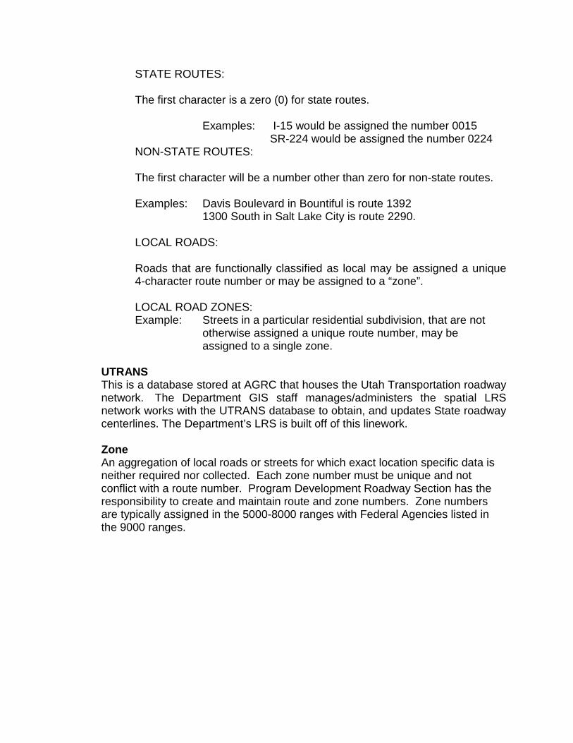
STATE ROUTES: The first character is a zero (0) for state routes.
Examples: I-15 would be assigned the number 0015 SR-224 would be assigned the number 0224
NON-STATE ROUTES: The first character will be a number other than zero for non-state routes.
Examples: Davis Boulevard in Bountiful is route 1392 1300 South in Salt Lake City is route 2290.
LOCAL ROADS: Roads that are functionally classified as local may be assigned a unique 4-character route number or may be assigned to a “zone”.
LOCAL ROAD ZONES: Example: Streets in a particular residential subdivision, that are not
otherwise assigned a unique route number, may be assigned to a single zone.
UTRANS This is a database stored at AGRC that houses the Utah Transportation roadway network. The Department GIS staff manages/administers the spatial LRS network works with the UTRANS database to obtain, and updates State roadway centerlines. The Department’s LRS is built off of this linework.
Zone An aggregation of local roads or streets for which exact location specific data is neither required nor collected. Each zone number must be unique and not conflict with a route number. Program Development Roadway Section has the responsibility to create and maintain route and zone numbers. Zone numbers are typically assigned in the 5000-8000 ranges with Federal Agencies listed in the 9000 ranges.

Procedures General Information UDOT 07-20.1 Responsibility: Highway Reference Manager Actions
1. Coordinate required activities with the Division of Traffic and Safety, Maintenance Division, Utah Highway Patrol, Traffic Operations Center, and the appropriate Region Office, including the Region Public Information Coordinator.
2. Identify and mark the locations for mileposts on all State Routes. Use a
calibrated electronic Distance Measuring Instrument (DMI) to measure distance on each route beginning at the start of the route and continuing in the positive direction until the end of the route is reached. Mark locations for mileposts to be placed at each exact whole mile or as near to it as possible within 50 feet. Omit the post if an obstruction prevents a post from being placed within 50 feet of its exact whole mile. Mark a location for the post on the negative side directly opposite the position of the post on the positive side on divided routes. Mark a location for a Post “0" at the beginning of each route unless the beginning of the route is physically evident.
3. Use a calibrated electronic DMI to measure the MP (accumulated
mileage) of each one of the features to be published in the Highway Reference online for every State Route. Refer to this procedure Step 4. Include features on both the positive and negative sides of the route and compile those into a single listing on divided highways. Measurement will be made while traveling in the positive direction therefore the identification of features on the negative side can be made by either:
a. Observing the feature from the positive side and marking the
location when a position directly opposite the feature is reached. b. Completing the identification of features on the positive side then
crossing to the negative side to measure the location of the feature in relation to the mileposts established there. Use a mathematical interpolation to establish the MP of the feature if the mileposts on the negative side are not exactly one mile apart due to differences in alignment.
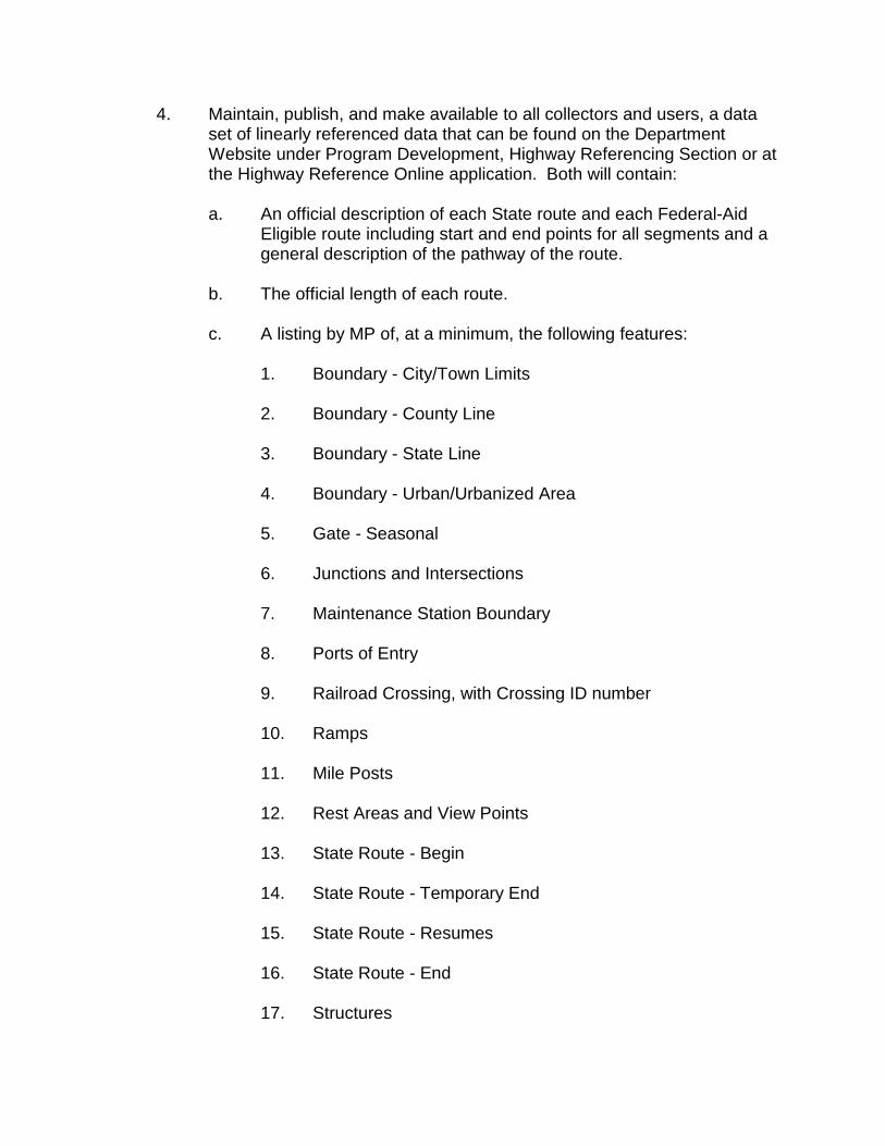
4. Maintain, publish, and make available to all collectors and users, a data set of linearly referenced data that can be found on the Department Website under Program Development, Highway Referencing Section or at the Highway Reference Online application. Both will contain:
a. An official description of each State route and each Federal-Aid
Eligible route including start and end points for all segments and a general description of the pathway of the route.
b. The official length of each route.
c. A listing by MP of, at a minimum, the following features:
1. Boundary - City/Town Limits 2. Boundary - County Line 3. Boundary - State Line 4. Boundary - Urban/Urbanized Area 5. Gate - Seasonal 6. Junctions and Intersections 7. Maintenance Station Boundary 8. Ports of Entry 9. Railroad Crossing, with Crossing ID number 10. Ramps 11. Mile Posts 12. Rest Areas and View Points 13. State Route - Begin 14. State Route - Temporary End 15. State Route - Resumes 16. State Route - End 17. Structures

d. A set of interchange diagrams indicating ramp numbers.
5. Develop and maintain a route nomenclature for all routes within the State
of Utah for use in data exchange.
6. Maintain a historic comparison of changes to routes such as nomenclature, alignment, ownership, or distance.
7. Notify all Department and external users of updates or changes to the
linear reference system each year with a data file available for use by computer systems and through hard copy, e-mail, or other form. Notify all users immediately upon completion of installation of the new mileposts in the event of a newly mileposted or re-mileposted route and make the new list for that route available at that time.
8. Maintain a current set of interchange diagrams indicating ramp numbers.
Responsibility: Maintenance
9. Place or replace mileposts exactly where indicated by the Highway Reference Manager.
10. Notify the Highway Reference Manager immediately when mileposting of
a route has been completed so the Highway Reference Manager may make a proper and timely notification to all users.
Responsibility: Highway Reference Manager, Maintenance, and Regions
11. Follow the “Re-mileposting Decision Matrix” for re--mileposting in the event of any changes to state routes such as a realignment, commission action, addition, or removal of mileage.
12. Fund all re-mileposting activities from the project and follow the”Re-
mileposting Decision Matrix” when a route change is caused from a project.
13. Review re-mileposting activities first and then decide required actions
based on the extent of the error and its effect on the roadway when a route has been identified as having mileposting errors.
Responsibility: LRS Manager/GIS Analyst
14. Coordinate with the Highway Reference Manager to verify the most current Highway Reference data is available and utilized.

15. Use the Statewide Streets data layer from AGRC’s UTRANS database to verify that route linework is accurate according to the Highway Reference description and that all linework is attributed accordingly.
a. Linework should fall within pavement according to the most current
aerial photo.
b. The database fields DOT_RTNAME and DOT_RTPART, at a minimum, should be updated or verified.
16. Update the floating ramps dataset according to the Highway Reference
description if ramps exist. 17. Create/Update calibration points within the Department Route Reference
Points data layer from AGRC’s UTRANS database.
a. Use a current aerial photo to visually identify features collected in the Highway Reference data, typically: intersections, structures, and cattle guards.
b. Verify route beginning and route ending points are present. c. Use part start and part end points where applicable. d. Populate or update attributes accordingly as calibration points are
created or updated based on the spatial location acquired from the aerial photo,
e. Give special attention to LABEL, RT_NAME, and RT_PART to
verify they correspond to the linework attributes. f. Sparingly create calibration points for purposes of error checking to
allow for non-calibration point features to be used as verification and to reduce the number of objects that may require future adjustments.
19. Calibrate the route after calibration points are created.
20. Plot all features from the Highway reference data as events on the route
once the route is calibrated.

21. Use the spatial location of features identified in the Highway Reference data that are identifiable in the aerial photo and not used as calibration points to verify the correctness of the calibration.
a. All plotted events should be within 50 feet of their respective
location on the aerial photo.
22. Improve the calibration as necessary by adding or removing calibration points and re-calibrating the route.
23. Publish the calibrated route to the Department’s official LRS dataset once
the route is verified and accepted.
24. Note that some lower function routes may require less detail in their calibration due to the reduced amount of data associated with them.
Responsibility: All Department Employees
25. Use the approved highway linear referencing method in correspondence, business transactions, inventory pursuits, and other activities where there is the need to share data or otherwise communicate with exactness the linear location of an event or feature.
26. Update computer systems and documents as needed to incorporate the
updates released by the Highway Reference Manager.