hitachi data ingestor - support.hitachivantara.com using the replication functionality.....6- 22...
TRANSCRIPT

Hitachi Data IngestorInstallation and Configuration Guide
MK-90HDI002-18
Product Version
Getting Help
Contents

© 2010 - 2015 Hitachi, Ltd. All rights reserved.
No part of this publication may be reproduced or transmitted in any form or by any means,electronic or mechanical, including photocopying and recording, or stored in a database or retrievalsystem for any purpose without the express written permission of Hitachi, Ltd.
Hitachi, Ltd., reserves the right to make changes to this document at any time without notice andassumes no responsibility for its use. This document contains the most current information availableat the time of publication. When new or revised information becomes available, this entiredocument will be updated and distributed to all registered users.
Some of the features described in this document might not be currently available. Refer to the mostrecent product announcement for information about feature and product availability, or contactHitachi Data Systems Corporation at https://portal.hds.com.
Notice: Hitachi, Ltd., products and services can be ordered only under the terms and conditions ofthe applicable Hitachi Data Systems Corporation agreements. The use of Hitachi, Ltd., products isgoverned by the terms of your agreements with Hitachi Data Systems Corporation.
Hitachi is a registered trademark of Hitachi, Ltd., in the United States and other countries. HitachiData Systems is a registered trademark and service mark of Hitachi, Ltd., in the United States andother countries.
Archivas, Essential NAS Platform, HiCommand, Hi-Track, ShadowImage, Tagmaserve, Tagmasoft,Tagmasolve, Tagmastore, TrueCopy, Universal Star Network, and Universal Storage Platform areregistered trademarks of Hitachi Data Systems Corporation.
AIX, AS/400, DB2, Domino, DS8000, Enterprise Storage Server, ESCON, FICON, FlashCopy, IBM,Lotus, OS/390, RS6000, S/390, System z9, System z10, Tivoli, VM/ESA, z/OS, z9, zSeries, z/VM, z/VSE are registered trademarks and DS6000, MVS, and z10 are trademarks of International BusinessMachines Corporation.
All other trademarks, service marks, and company names in this document or website areproperties of their respective owners.
Microsoft product screen shots are reprinted with permission from Microsoft Corporation.
iiHitachi Data Ingestor Installation and Configuration Guide

Contents
Preface..................................................................................................xiIntended audience....................................................................................................xiiProduct version........................................................................................................xiiRelease notes...........................................................................................................xiiOrganization of HDI manuals.....................................................................................xiiReferenced documents.............................................................................................xiiiAbbreviation conventions..........................................................................................xvDocument conventions............................................................................................xviiConvention for storage capacity values....................................................................xviiiGetting help...........................................................................................................xviiiComments.............................................................................................................xviii
1 Overview of Hitachi Data Ingestor..........................................................1-1What is Hitachi Data Ingestor?.................................................................................1-2Linkage with Hitachi Content Platform......................................................................1-4
2 System Configuration............................................................................2-1Hardware configurations.........................................................................................2-2
Configurations of storage systems and nodes.....................................................2-2External servers and devices required in an HDI system......................................2-2External servers and devices required in an HDI system when using the NDMPfunctionality.....................................................................................................2-6
Network configurations...........................................................................................2-7Network configuration required to use CIFS shares...........................................2-11
When the CIFS client and the node are connected to the same subnet......2-12When the CIFS client and the node are connected to different subnets.....2-14When the CIFS service is used with multiple ports...................................2-16
Using trunking in an HDI system......................................................................2-17Features...............................................................................................2-18Trunking prerequisites...........................................................................2-18Recommended trunking configurations...................................................2-19Examples of a network configuration......................................................2-20
Using a VLAN in an HDI system.......................................................................2-22Features...............................................................................................2-22VLAN prerequisites................................................................................2-23
iiiHitachi Data Ingestor Installation and Configuration Guide

VLAN interface setting...........................................................................2-23Example network configurations.............................................................2-23
Using both a VLAN and trunking in an HDI system............................................2-24System configurations when linking with an HCP system..........................................2-24
Linking to an HCP system that shares the same storage system.........................2-25When linkage is made via a network................................................................2-26
3 Environment Settings for External Servers..............................................3-1External servers required in an HDI system..............................................................3-3Environment settings for a management server........................................................3-5
Requirements for a management server.............................................................3-5Management server cluster configuration...........................................................3-9Executing a command with administrative privileges from a command prompt....3-10
Environment settings for a management console.....................................................3-11Requirements for a management console.........................................................3-11Settings when Internet Explorer is used on the management console.................3-14
Notes when using Internet Explorer........................................................3-14Internet Explorer settings.......................................................................3-15
Settings when Firefox is used on the management console................................3-17Environment settings for the NIS server..................................................................3-18Environment settings for the LDAP server...............................................................3-19
Notes on using an LDAP server........................................................................3-20Notes on using OpenLDAP...............................................................................3-20Notes on using Sun Java System Directory Server.............................................3-21Notes on using ADAM......................................................................................3-22Settings example when using OpenLDAP..........................................................3-22
Creating a schema file...........................................................................3-23Setting the index directive......................................................................3-23
Settings example when using Sun Java System Directory Server........................3-24Creating a schema file...........................................................................3-24Setting an index....................................................................................3-25
Settings example when using ADAM.................................................................3-26Creating a schema file...........................................................................3-26Setting an index....................................................................................3-28
Environment settings for the domain controller.......................................................3-29Environment settings for the KDC server.................................................................3-30Environment settings for the RADIUS server...........................................................3-31Environment settings for the SNMP manager...........................................................3-32
Configuring the machine to be used for the SNMP manager...............................3-32Setting specific-traps.......................................................................................3-32Obtaining a definition file for Hitachi MIB objects..............................................3-33SNMP agent version........................................................................................3-34Trap notification when the SNMP agent starts or stops......................................3-34
Environment settings for the NTP server.................................................................3-34Environment settings for the scan server................................................................3-35Environment settings for a tape device connected to a node via a SAN.....................3-39
Registering tape drive information....................................................................3-39Enabling the registration information of tape drives...........................................3-39Unregistering tape drive information................................................................3-40Notes on setting up a tape device connected to a node via a SAN......................3-40Replacing of tape devices................................................................................3-40Stopping use of a tape device..........................................................................3-41
ivHitachi Data Ingestor Installation and Configuration Guide
SMTP server environment settings..........................................................................3-41DHCP server environment settings.........................................................................3-41DNS server environment settings...........................................................................3-42
4 About HDI............................................................................................4-1Notes on managing an HDI system (required reading)...............................................4-3About cluster configurations....................................................................................4-6About client user information...................................................................................4-8About HDI with user mapping..................................................................................4-9
Domains that allow access to an HDI system......................................................4-9User mapping methods...................................................................................4-11
User mapping using RIDs.......................................................................4-12User mapping using LDAP......................................................................4-12User mapping using the Active Directory schema.....................................4-12
Changing the user mapping method.................................................................4-13Examples of assigning user IDs and group IDs with user mapping using RIDs.....4-15
About file systems.................................................................................................4-19Creating an LU (device file) or volume group....................................................4-20Notes on allocating LUs...................................................................................4-21Notes on using the local data encryption functionality........................................4-23Issuing warnings about file system usage.........................................................4-24When the striping function is used...................................................................4-28
Overview of the striping function............................................................4-28Notes on the striping function................................................................4-30
Selecting which ACL type to use for a file system..............................................4-30Migrating to a file system that uses the Advanced ACL type...............................4-33
Notes on migrating a file system.............................................................4-35Estimating the file system size after a migration......................................4-37How to migrate a file system..................................................................4-38
Using WORM file systems................................................................................4-40Autocommitting a file to change it to a WORM file...................................4-40Manually changing a file to a WORM file from a client..............................4-41Precautions regarding WORM file system operation..................................4-42
Using single instancing to reduce used capacity................................................4-42Using CIFS bypass traverse checking................................................................4-43
About setting quotas.............................................................................................4-44Information that can be specified for quota management..................................4-46
Specifying a quota for each user, group, or directory...............................4-46Specifying a default quota......................................................................4-47Specifying a grace period.......................................................................4-47Specifying a quota monitoring method....................................................4-47Notes on specifying quotas....................................................................4-50
Specifying quotas for each file system..............................................................4-51Specifying subtree quotas................................................................................4-52Notes on quota management...........................................................................4-53Typical example of quota management............................................................4-55
About file sharing..................................................................................................4-56What to check before using NFS shares............................................................4-56What to check before using CIFS shares...........................................................4-57Items to check before creating a CIFS share.....................................................4-58Setting home drives........................................................................................4-58Linking with MMC...........................................................................................4-58
vHitachi Data Ingestor Installation and Configuration Guide

Using CIFS access logs....................................................................................4-58Configuring ACLs in a file system using the Classic ACL type..............................4-58Using the TFTP service....................................................................................4-59
About real-time virus scanning...............................................................................4-60Notes on using the real-time virus scanning functionality...................................4-60
Real-time virus scanning operations........................................................4-61When an error occurs during real-time virus scanning..............................4-61Temporary files.....................................................................................4-62WORM files...........................................................................................4-63Stub files..............................................................................................4-64Managing the Anti-Virus Enabler library trace log file (antiviruslib.trace)....4-64Displaying the number of logged-in CIFS clients......................................4-64
Notes on registering a scan server...................................................................4-64Planning real-time virus scanning operations.....................................................4-65
Problems caused by a decrease in the performance of real-time virus scanning............................................................................................................4-65Checking the scanning conditions and log files.........................................4-66Checking the report information file (antivirus_report.csv)........................4-67Checking the user statistics file (antivirus_stat.csv)..................................4-70Determining how to improve the performance.........................................4-71
Revising the scanning conditions for the real-time virus scanning functionality....4-74Increasing the cache size.......................................................................4-74Increasing the scan timeout period.........................................................4-75Reducing the number of times a virus scan is performed..........................4-75Suppressing the creation of temporary files.............................................4-75Selecting scan targets............................................................................4-76
About system settings...........................................................................................4-76About errors.........................................................................................................4-77
Error information on the management server....................................................4-78Node error information ...................................................................................4-78Using SNMP to send error information..............................................................4-78Using the email error notification function.........................................................4-79
About monitoring systems with SNMP.....................................................................4-79About importing data from other file servers...........................................................4-80
System configurations when data is imported from other file servers..................4-81Points to check before importing data from another file server...........................4-82
About clients using file systems..............................................................................4-85Notes on using a file system from an NFS client................................................4-85Notes on using a file system from a CIFS client.................................................4-86Note on using a file system from an FTP client..................................................4-86
5 Backup Operations in an HDI System.....................................................5-1Overview of the backup functionality........................................................................5-2Using the NDMP functionality...................................................................................5-2
Overview of the NDMP functionality...................................................................5-2Estimating the capacity of the backup media......................................................5-3Data to be backed up or restored......................................................................5-5Recommended time to perform backup and restore operation.............................5-5Performing an incremental backup.....................................................................5-5About access control for the NDMP server..........................................................5-7Communication path used for backup or restore operations.................................5-8Operations that cannot be executed during backup or restoration........................5-8
viHitachi Data Ingestor Installation and Configuration Guide

Notes on operations using File Services Manager................................................5-9Precautions on starting the OS on a node...........................................................5-9Limitations on the functionality of the backup management software...................5-9Notes on backing up and restoring WORM file systems......................................5-10
Notes on backing up a WORM file system................................................5-10Notes on restoring a WORM file system...................................................5-11
Backing up and restoring a file system for which single instancing is enabled......5-11
6 Linking HDI and HCP............................................................................6-1Functionalities for managing migration.....................................................................6-2
Correspondence between file systems and namespaces.......................................6-2Changing files to stub files................................................................................6-3Internal processing before and after transferring data.........................................6-4Recalling files to an HDI system.........................................................................6-5Restoring files by using version management.....................................................6-6
Behavior when a custom schedule is enabled............................................6-7Example of processing executed according to a custom schedule................6-8
What must be checked before linking an HDI system with an HCP system................6-11Accounts used for accessing the HCP system from HDI systems.........................6-17
For HCP version 5.0 or later...................................................................6-17For HCP version 4.1 or earlier.................................................................6-17
Settings required on the HCP system when linking with the HCP system.............6-18Creating a tenant..................................................................................6-18Creating a migration-destination namespace...........................................6-18Creating a namespace for saving system settings....................................6-21When using the replication functionality..................................................6-22When upgrading software on a node by using an installation file on HCP...6-22
Sharing HCP data migrated from other HDI systems as read-only.......................6-27Allowing another HDI to use migrated HCP data for each end user.....................6-28
Notes on allowing migrated HCP data to be used from another HDI for eachend user...............................................................................................6-30General considerations before configuring and using home-directory-roaming............................................................................................................6-32
Using data migrated to the HCP system to recover an HDI system.....................6-33
7 Installing Hitachi File Services Manager and Setting Up Its Environment. . .7-1Installing and uninstalling Hitachi File Services Manager............................................7-2
Performing a new installation of Hitachi File Services Manager.............................7-2Performing an upgrade or overwrite installation of Hitachi File Services Manager...7-7Uninstalling Hitachi File Services Manager.........................................................7-10
Removing Hitachi File Services Manager prerequisites..............................7-10Performing an uninstallation...................................................................7-11
Prerequisites for installing Hitachi File Services Manager....................................7-12Installing and uninstalling Hitachi File Services Manager (if the management server isrunning in a cluster configuration)..........................................................................7-15
Performing a new installation of Hitachi File Services Manager (if the managementserver is running in a cluster configuration)......................................................7-16
Changing the management server to a cluster configuration.....................7-16Installations in cluster environments prerequisites...................................7-16Performing a new installation on the executing node of the managementserver...................................................................................................7-16
viiHitachi Data Ingestor Installation and Configuration Guide

Performing a new installation on the standby node of the management server............................................................................................................7-21
Performing an upgrade or overwrite installation of Hitachi File Services Manager (ifthe management server is running in a cluster configuration)............................7-23
Upgrade or overwrite installation on the executing node of the managementserver...................................................................................................7-23Upgrade or overwrite installation on the standby node of the managementserver...................................................................................................7-25
Performing a new installation, upgrade installation, or overwrite installation ofHitachi File Services Manager (when Hitachi Command Suite products are running ina cluster configuration)...................................................................................7-26Uninstalling Hitachi File Services Manager (if the management server is running in acluster configuration)......................................................................................7-30
Starting and stopping Hitachi File Services Manager................................................7-31List of resident processes................................................................................7-31Starting Hitachi File Services Manager..............................................................7-32
Using the Windows menu.......................................................................7-32Using a command..................................................................................7-33
Stopping Hitachi File Services Manager.............................................................7-33Using the Windows menu.......................................................................7-33Using a command..................................................................................7-33
Checking whether Hitachi File Services Manager is running................................7-34Using the Windows menu.......................................................................7-34Using a command..................................................................................7-34
Managing the system administrator account............................................................7-35Setting the security related to the system administrator account........................7-36
Setting the password conditions.............................................................7-37Specifying the settings related to automatic account locking.....................7-38
Specifying the settings related to locking the system account.............................7-39Unlocking a system administrator account........................................................7-40Performing an external authentication by using an LDAP server.........................7-40
Data structure model and authentication method for LDAP authentication. 7-42Modifying exauth.properties for LDAP authentication................................7-44Setting LDAP user information (LDAP authentication)...............................7-52Checking the connection status of external authentication and authorizationservers (LDAP authentication)................................................................7-54
Performing an external authentication by using a RADIUS server.......................7-56Modifying exauth.properties for RADIUS authentication............................7-57Setting LDAP user information (RADIUS authentication)...........................7-65Setting a shared secret (RADIUS authentication).....................................7-67Checking the connection status of external authentication and authorizationservers (RADIUS authentication)............................................................7-68
Performing an external authentication by using a KDC server.............................7-69Modifying exauth.properties for Kerberos authentication..........................7-70Setting LDAP user information (Kerberos authentication)..........................7-77Checking the connection status of external authentication and authorizationservers (Kerberos authentication)...........................................................7-79Encryption types for Kerberos authentication...........................................7-81
Connecting to Device Manager to manage user accounts...................................7-82If you install Hitachi File Services Manager on a management server on whichDevice Manager version 8.0 or later has already been installed.................7-82
viiiHitachi Data Ingestor Installation and Configuration Guide

If you install Hitachi File Services Manager and Device Manager on differentmachines..............................................................................................7-82
Setting the security for Hitachi Command Suite Common Component(communication with an LDAP server)..............................................................7-83
Obtaining a certificate for an LDAP server...............................................7-84Importing an LDAP server certificate to the truststore file.........................7-85
Setting up the Hitachi File Services Manager environment........................................7-86Changing the log file settings...........................................................................7-86Changing the update setting of the license information......................................7-88Changing the port numbers used by Hitachi Command Suite Common Component.....................................................................................................................7-89Configuring SSL..............................................................................................7-91
Setting up SSL......................................................................................7-91Disabling the SSL settings......................................................................7-96Acquiring a CA-issued certificate.............................................................7-97Changing the port number assigned for SSL............................................7-97
Importing the required SSL certificate for communication between the node andmanagement server........................................................................................7-98Configuring the warning banner.......................................................................7-98
Creating a message file..........................................................................7-99Registering a message...........................................................................7-99Deleting a message.............................................................................7-100
Acquiring and checking the Hitachi File Services Manager audit logs.................7-101Settings to acquire the Hitachi File Services Manager audit logs..............7-102Checking Hitachi File Services Manager audit log data............................7-103
Setting the memory heap size........................................................................7-105Maintenance of the management server...............................................................7-107
Backing up or restoring the database of the management server......................7-107Backing up the database......................................................................7-107Restoring the database........................................................................7-109
Migrating the management server from a non-cluster configuration into a clusterconfiguration................................................................................................7-112
Migrating to cluster configurations prerequisites.....................................7-112Settings on the executing node of the management server.....................7-113Settings on the standby node of the management server.......................7-117
Migrating the database of the management server..........................................7-120Migrating database prerequisites..........................................................7-120Exporting the database on the migration source server..........................7-121Importing the database on the migration target server...........................7-123
Changing the host name or IP address of the management server...................7-126Adjusting the management server time..........................................................7-129Disconnecting the management server network..............................................7-130Changing the JDK.........................................................................................7-132
A ACLs Created After the File System Is Migrated to That of the Advanced ACLType...................................................................................................A-1ACLs Created After the File System Is Migrated to That of the Advanced ACL Type.....A-2
B Using the Node Power Lamp Switch or Power Button to Start or Stop the OS..........................................................................................................B-1Starting an OS........................................................................................................B-2
ixHitachi Data Ingestor Installation and Configuration Guide

Forcibly Stopping an OS..........................................................................................B-2
C Layout of Node Ports............................................................................C-1Port layout.............................................................................................................C-2
D Status of IPv6 Support in External Servers and Services.........................D-1List of external servers and services available on IPv6...............................................D-2
E Attributes of Directories and Files to Be Backed Up or Restored...............E-1Attributes to be backed up......................................................................................E-2Attributes to be restored.........................................................................................E-3
F Acronyms.............................................................................................F-1Acronyms used in the HDI manuals..........................................................................F-2
Glossary
Index
xHitachi Data Ingestor Installation and Configuration Guide

Preface
This manual contains information that you need to know before operating theHitachi Data Ingestor (HDI) systems. This manual also explains how to set upthe systems.
□ Intended audience
□ Product version
□ Release notes
□ Organization of HDI manuals
□ Referenced documents
□ Abbreviation conventions
□ Document conventions
□ Convention for storage capacity values
□ Getting help
□ Comments
Preface xiHitachi Data Ingestor Installation and Configuration Guide

Intended audienceThis manual is intended for system administrators who operate and managean HDI system.
In addition, the user must have:
• A basic knowledge of storage systems
• A basic knowledge of Hitachi Content Platform (HCP) systems
• A basic knowledge of networks
• A basic knowledge of file sharing services
• A basic knowledge of SAN
• A basic knowledge of CIFS
• A basic knowledge of NFS
• A basic knowledge of UNIX
• A basic knowledge of Windows
• A basic knowledge of Web browsers
Product versionThis document revision applies to Hitachi Data Ingestor version 5.1.1 or later.
Release notesRelease notes can be found on the documentation CD. Release notes containrequirements and more recent product information that may not be fullydescribed in this manual. Be sure to review the release notes beforeinstallation.
Organization of HDI manualsHDI manuals are organized as shown below.
Note that whether HDI nodes can be set up in a redundant configurationdepends on the HDI model. A configuration where nodes are made redundantis called a cluster configuration, and a configuration where a node is notmade redundant with another node is called a single-node configuration.Which manuals you need to read depends on which configuration you aregoing to use.
Manual name Description
Hitachi Data Ingestor Installation andConfiguration Guide (This manual)
You must read this manual first to use an HDIsystem.
This manual contains the information that youmust be aware of before starting HDI system
xii PrefaceHitachi Data Ingestor Installation and Configuration Guide

Manual name Description
operation, as well as the environment settingsfor an external server.
Hitachi Data Ingestor Cluster GettingStarted Guide, MK-90HDI001
This manual explains how to set up an HDIsystem in a cluster configuration.
Hitachi Data Ingestor ClusterAdministrator's Guide, MK-90HDI038
This manual provides procedures for using HDIsystems in a cluster configuration, as well asprovides GUI references.
Hitachi Data Ingestor ClusterTroubleshooting Guide, MK-90HDI029
This manual provides troubleshootinginformation for HDI systems in a clusterconfiguration.
Hitachi Data Ingestor Single NodeGetting Started Guide, MK-90HDI028
This manual explains how to set up an HDIsystem in a single-node configuration.
Hitachi Data Ingestor Single NodeAdministrator's Guide, MK-90HDI039
This manual explains the procedures for usingHDI systems in a single-node configuration, aswell as provides GUI references.
Hitachi Data Ingestor Single NodeTroubleshooting Guide, MK-90HDI030
This manual provides troubleshootinginformation for HDI systems in a single-nodeconfiguration.
Hitachi Data Ingestor CLIAdministrator's Guide, MK-90HDI034
This manual describes the syntax of thecommands that can be used for HDI systems ina cluster configuration or a single-nodeconfiguration.
Hitachi Data Ingestor API References,MK-90HDI026
This manual explains how to use the API for HDIsystems in a cluster configuration or a single-node configuration.
Hitachi Data Ingestor Error Codes,MK-90HDI005
This manual contains messages for HDI systemsin a cluster configuration or a single-nodeconfiguration.
Hitachi Data Ingestor File SystemProtocols (CIFS/NFS) Administrator'sGuide, MK-90HDI035
This manual contains the things to keep in mindbefore using the CIFS or NFS service of an HDIsystem in a cluster configuration or a single-node configuration from a CIFS or NFS client.
Referenced documents
Hitachi Command Suite products
• Hitachi Command Suite Software User Guide
• Hitachi Command Suite Software CLI Reference Guide
• Hitachi Command Suite Software Messages Guide
• Hitachi Command Suite Software Installation and Configuration Guide
• Hitachi Command Suite Software Configuration Reference Guide
• Hitachi Command Suite Replication Manager Software Configuration Guide
• Hitachi Command Suite Tuning Manager Software Installation Guide
Preface xiiiHitachi Data Ingestor Installation and Configuration Guide
Hitachi Virtual Storage Platform G1000
• Hitachi Data Ingestor Enterprise Array Features Administrator's Guide
Hitachi Virtual Storage Platform
• Hitachi Data Ingestor Enterprise Array Features Administrator's Guide
Hitachi Universal Storage Platform V/VM
• Hitachi Data Ingestor Enterprise Array Features Administrator's Guide
Hitachi Unified Storage VM
• Hitachi Data Ingestor Enterprise Array Features Administrator's Guide
Hitachi Unified Storage 100 series
• Hitachi Data Ingestor Modular Array Features Administrator's Guide
• Hitachi Storage Navigator Modular 2 Graphical User Interface (GUI) User'sGuide
Hitachi AMS2000 series
• Hitachi Data Ingestor Modular Array Features Administrator's Guide
• Hitachi Storage Navigator Modular 2 Graphical User Interface (GUI) User'sGuide
Hitachi Content Platform
• Hitachi Content Platform Administering HCP
• Hitachi Content Platform Managing a Tenant and Its Namespaces
• Hitachi Content Platform Managing the Default Tenant and Namespace
• Hitachi Content Platform Replicating Tenants and Namespaces
• Hitachi Content Platform HCP Management API Reference
• Hitachi Content Platform Using a Namespace
• Hitachi Content Platform Using the Default Namespace
• Hitachi Content Platform HCP Metadata Query API Reference
• Hitachi Content Platform Searching Namespaces
• Hitachi Content Platform Using HCP Data Migrator
• Hitachi Content Platform Installing an HCP System
• Hitachi Content Platform Third-Party Licenses and Copyrights
• Hitachi Content Platform HCP-DM Third-Party Licenses and Copyrights
• Hitachi Content Platform Installing an HCP SAIN System - Final On-siteSetup
• Hitachi Content Platform Installing an HCP RAIN System - Final On-siteSetup
xiv PrefaceHitachi Data Ingestor Installation and Configuration Guide

Abbreviation conventionsThis manual uses the following abbreviations for product names:
Abbreviation Full name or meaning
Active Directory Active Directory(R)
ADAM Active Directory(R) Application Mode 1.0
Compute Systems Manager Hitachi Compute Systems Manager
Device Manager Hitachi Device Manager Software
Dynamic Provisioning Hitachi Dynamic Provisioning
Dynamic Tiering Hitachi Dynamic Tiering
File Services Manager A generic name for the following:
• Configuration Manager
• Hitachi File Services Manager
Firefox Mozilla Firefox(R)
Global Link Manager Hitachi Global Link Manager Software
HCP Hitachi Content Platform
HDI Hitachi Data Ingestor
Hitachi AMS2000 series Hitachi Adaptable Modular Storage 2000 series
HUS100 series A generic name for the following:
• Hitachi Unified Storage 150
• Hitachi Unified Storage 130
• Hitachi Unified Storage 110
HUS VM Hitachi Unified Storage VM
Internet Explorer Windows(R) Internet Explorer(R)
OpenLDAP OpenLDAP 2.x
Replication Manager Hitachi Replication Manager Software
ShadowImage A generic name for the following:
• ShadowImage
• ShadowImage in-system replication
Solaris 10 Solaris 10 Operating System for SPARC Platforms
Sun Java System DirectoryServer
Sun Java(TM) System Directory Server 5.2
Tiered Storage Manager Hitachi Tiered Storage Manager Software
TrueCopy A generic name for the following:
• TrueCopy
• TrueCopy Asynchronous
• TrueCopy Extended Distance
• TrueCopy remote replication
Preface xvHitachi Data Ingestor Installation and Configuration Guide

Abbreviation Full name or meaning
Tuning Manager Hitachi Tuning Manager Software
Universal Storage Platform V/VM
A generic name for the following:
• Hitachi Universal Storage Platform V
• Hitachi Universal Storage Platform VM
Virtual Storage Platform Hitachi Virtual Storage Platform
VSP G1000 Hitachi Virtual Storage Platform G1000
Windows Microsoft(R) Windows(R) Operating System
Windows 8 A generic name for the following:
• Microsoft(R) Windows(R) 8 32-bit
• Microsoft(R) Windows(R) 8 64-bit
• Microsoft(R) Windows(R) 8 Enterprise 32-bit
• Microsoft(R) Windows(R) 8 Enterprise 64-bit
• Microsoft(R) Windows(R) 8 Pro 32-bit
• Microsoft(R) Windows(R) 8 Pro 64-bit
Windows Server 2003 A generic name for the following:
• Microsoft(R) Windows Server(R) 2003, StandardEdition Operating System
• Microsoft(R) Windows Server(R) 2003, EnterpriseEdition Operating System
• Microsoft(R) Windows Server(R) 2003, DatacenterEdition Operating System
• Microsoft(R) Windows Server(R) 2003, Web EditionOperating System
Windows Server 2003 R2 A generic name for the following:
• Microsoft(R) Windows Server(R) 2003 R2, StandardEdition
• Microsoft(R) Windows Server(R) 2003 R2,Enterprise Edition
• Microsoft(R) Windows Server(R) 2003 R2,Datacenter Edition
Windows Server 2008 A generic name for the following:
• Microsoft(R) Windows Server(R) 2008 Datacenter
• Microsoft(R) Windows Server(R) 2008 Enterprise
• Microsoft(R) Windows Server(R) 2008 Standard
Windows Server 2008 R2 A generic name for the following:
• Microsoft(R) Windows Server(R) 2008 R2Datacenter
• Microsoft(R) Windows Server(R) 2008 R2 Enterprise
• Microsoft(R) Windows Server(R) 2008 R2 Standard
Windows Server 2012 A generic name for the following:
• Microsoft(R) Windows Server(R) 2012 Datacenter
• Microsoft(R) Windows Server(R) 2012 Standard
xvi PrefaceHitachi Data Ingestor Installation and Configuration Guide
Abbreviation Full name or meaning
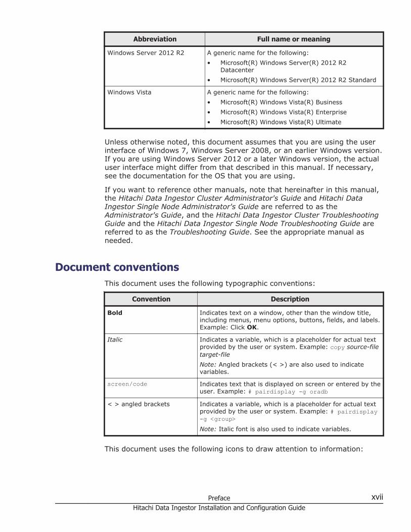
Windows Server 2012 R2 A generic name for the following:
• Microsoft(R) Windows Server(R) 2012 R2Datacenter
• Microsoft(R) Windows Server(R) 2012 R2 Standard
Windows Vista A generic name for the following:
• Microsoft(R) Windows Vista(R) Business
• Microsoft(R) Windows Vista(R) Enterprise
• Microsoft(R) Windows Vista(R) Ultimate
Unless otherwise noted, this document assumes that you are using the userinterface of Windows 7, Windows Server 2008, or an earlier Windows version.If you are using Windows Server 2012 or a later Windows version, the actualuser interface might differ from that described in this manual. If necessary,see the documentation for the OS that you are using.
If you want to reference other manuals, note that hereinafter in this manual,the Hitachi Data Ingestor Cluster Administrator's Guide and Hitachi DataIngestor Single Node Administrator's Guide are referred to as theAdministrator's Guide, and the Hitachi Data Ingestor Cluster TroubleshootingGuide and the Hitachi Data Ingestor Single Node Troubleshooting Guide arereferred to as the Troubleshooting Guide. See the appropriate manual asneeded.
Document conventionsThis document uses the following typographic conventions:
Convention Description
Bold Indicates text on a window, other than the window title,including menus, menu options, buttons, fields, and labels.Example: Click OK.
Italic Indicates a variable, which is a placeholder for actual textprovided by the user or system. Example: copy source-filetarget-file
Note: Angled brackets (< >) are also used to indicatevariables.
screen/code Indicates text that is displayed on screen or entered by theuser. Example: # pairdisplay -g oradb
< > angled brackets Indicates a variable, which is a placeholder for actual textprovided by the user or system. Example: # pairdisplay-g <group>Note: Italic font is also used to indicate variables.
This document uses the following icons to draw attention to information:
Preface xviiHitachi Data Ingestor Installation and Configuration Guide
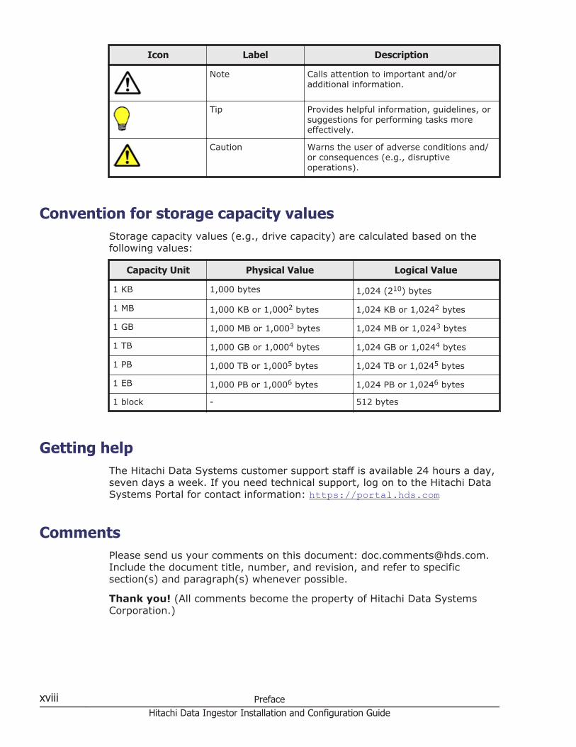
Icon Label Description
Note Calls attention to important and/oradditional information.
Tip Provides helpful information, guidelines, orsuggestions for performing tasks moreeffectively.
Caution Warns the user of adverse conditions and/or consequences (e.g., disruptiveoperations).
Convention for storage capacity valuesStorage capacity values (e.g., drive capacity) are calculated based on thefollowing values:
Capacity Unit Physical Value Logical Value
1 KB 1,000 bytes 1,024 (210) bytes
1 MB 1,000 KB or 1,0002 bytes 1,024 KB or 1,0242 bytes
1 GB 1,000 MB or 1,0003 bytes 1,024 MB or 1,0243 bytes
1 TB 1,000 GB or 1,0004 bytes 1,024 GB or 1,0244 bytes
1 PB 1,000 TB or 1,0005 bytes 1,024 TB or 1,0245 bytes
1 EB 1,000 PB or 1,0006 bytes 1,024 PB or 1,0246 bytes
1 block - 512 bytes
Getting helpThe Hitachi Data Systems customer support staff is available 24 hours a day,seven days a week. If you need technical support, log on to the Hitachi DataSystems Portal for contact information: https://portal.hds.com
CommentsPlease send us your comments on this document: [email protected] the document title, number, and revision, and refer to specificsection(s) and paragraph(s) whenever possible.
Thank you! (All comments become the property of Hitachi Data SystemsCorporation.)
xviii PrefaceHitachi Data Ingestor Installation and Configuration Guide
1Overview of Hitachi Data Ingestor
This chapter describes the features of, and gives a functional overview of,Hitachi Data Ingestor (HDI).
□ What is Hitachi Data Ingestor?
□ Linkage with Hitachi Content Platform
Overview of Hitachi Data Ingestor 1-1Hitachi Data Ingestor Installation and Configuration Guide

What is Hitachi Data Ingestor?An Hitachi Data Ingestor (HDI) system provides services that enable clientson different platforms to share data in storage systems. An HDI systemconsists of file servers called nodes and storage systems in which data iscompacted and stored. The HDI system provides a file system service toclients by way of the network ports on the nodes.
The HDI model determines whether HDI nodes can be set up in a redundantconfiguration. A configuration where nodes are made redundant is called acluster configuration, and a configuration where a node is not maderedundant with another node is called a single-node configuration.
From a management console, the system administrator of an HDI system canset up the system, monitor operating statuses, monitor for errors, changesettings, back up data, and restore data.
The following figure shows an overview of an HDI system.
Figure 1-1 Overview of an HDI system
The main features of an HDI system are as follows.
Provides an open data-sharing environment that fully utilizes legacy systems
1-2 Overview of Hitachi Data IngestorHitachi Data Ingestor Installation and Configuration Guide

While fully utilizing an enterprise's already-existing LAN environment, anHDI system can achieve integrated management of data on a storagesystem. Data on a storage system can be shared across heterogeneousplatforms.
Efficient and flexible capacity managementIn an HDI system linked to Dynamic Provisioning, which provides thecapacity virtualization functionality for storage systems, a virtual volumewhose capacity is larger than a physical volume on a storage system canbe allocated to a file system. Before a capacity shortage occurs, a diskcan be added without stopping the system, thereby improving theusability of the storage system and reducing installation costs. It is alsopossible to efficiently use free space on a volume allocated to a filesystem by checking the available capacity for each shared directoryaccording to operational preferences.
Ensures high availability in a cluster configurationIn an HDI system, two nodes are configured in a cluster to ensure thereliable delivery of services, such as NFS and CIFS services. If an erroroccurs in one node, services can be relocated to the other node in thecluster, ensuring service stability.By working together with the failover functionality, the HDI systemenables online maintenance of hardware, software, and the servicesprovided by the HDI system.
Ensures safetyIn an HDI system, Anti-Virus Enabler can perform real-time scanning toprotect valuable data on a file system from viruses.
Data persistence suitable for complianceFiles on file systems that support WORM (Write Once Read Many)functionality can be changed to WORM data, thereby preventingfalsification and deletion of data and providing long-term data persistencesuitable for regulatory compliance.
Secure data storage by using encryption technologyEncryption on user LUs used for file systems reduces the risk ofinformation leaks (Local data encryption). HDI systems use secret keycryptography (an XTS-AES cipher with a 256-bit key length). Encryptionrequires a corresponding license.
Backup operationsBy replicating data, an HDI system can protect valuable data shared on afile system from loss due to error or malfunctions.
Linkage with Hitachi Command Suite products in a cluster configurationAn HDI system can link with the following Hitachi Command Suiteproducts:
¢ Device ManagerBy linking with Device Manager, you can centrally manage thecorrespondence between volumes in storage systems and file
Overview of Hitachi Data Ingestor 1-3Hitachi Data Ingestor Installation and Configuration Guide

systems. You can also use single sign-on for the Hitachi CommandSuite products.
¢ Tuning ManagerYou can view the status of file system usage and performanceinformation for the OS on a node.
Data importing from other file serversYou can import file share data used in file servers other than HDI systemsto an HDI system. The data in multiple file servers can be importedsimultaneously. This allows you to integrate file server operations into anHDI system.HDI systems can import data while the target file system is in use. Accessfrom clients can be re-opened even if all files and directories have not yetbeen imported. This reduces the time that file system operation must bestopped.
Linkage with Hitachi Content PlatformHitachi Content Platform (HCP) systems archive large amounts of datacreated on various systems and store them long term. HCP systems allowquick access to archived data, in addition to high capacity scalability.
An HDI system that links with an HCP system can provide high-performancefile system services and, at the same time, efficiently manage the largeamounts of data that accumulates daily.
For example, by making files WORM (Write Once, Read Many) files to guardagainst tampering or deletion, and by regularly migrating infrequentlyaccessed files to an HCP system, you can effectively manage archived data toensure that file systems meet compliance requirements. If you make data ofan earlier version archived in an HCP system available to HDI clients, thoseclients can restore the data when necessary.
1-4 Overview of Hitachi Data IngestorHitachi Data Ingestor Installation and Configuration Guide

Figure 1-2 Linkage between an HDI system and an HCP system that sharea storage system
In addition, migrating the file system data on HDI systems running indistributed locations to a remote HCP system by way of a network enablesyou to centrally control data in a large-scale system. File systems in eachlocation are managed by HDI system administrators. The data received fromeach location is centrally managed by the HCP system administrator. Thedata centrally managed by an HCP system can be shared among HDI systemsrunning in distributed locations.
Overview of Hitachi Data Ingestor 1-5Hitachi Data Ingestor Installation and Configuration Guide

Figure 1-3 Linkage between HDI systems and a remote HCP system via anetwork
1-6 Overview of Hitachi Data IngestorHitachi Data Ingestor Installation and Configuration Guide

2System Configuration
This chapter describes HDI system configurations. This chapter also describessystem configurations in which HDI systems link with an HCP system.
□ Hardware configurations
□ Network configurations
□ System configurations when linking with an HCP system
System Configuration 2-1Hitachi Data Ingestor Installation and Configuration Guide
Hardware configurationsIn addition to storage systems and nodes, an HDI system includes externalservers and devices, on the network, that are required to provide file systemservices. This section describes HDI hardware configurations.
Configurations of storage systems and nodesAn HDI node that uses a storage system in either a cluster configuration orsingle-node configuration is a device connected to a storage system by wayof Fibre Channel, and can include various ports (such as data ports,management ports, and BMC ports), a DVD drive, and an internal hard diskdrive. For information about node hardware, see the applicable HDI manual.For the names and locations of ports, see Appendix C, Layout of Node Portson page C-1.
External servers and devices required in an HDI systemIn addition to a storage system and nodes, an HDI system also requires thefollowing external servers and devices:
Management consoleA computer required in order to use the GUI or commands. The followingprograms can also be used:
Storage NavigatorA program required for operating Universal Volume Manager when aVSP G1000, Virtual Storage Platform, Universal Storage Platform V/VM, or HUS VM storage system is used for an HDI system in a clusterconfiguration. This program can be used to check which drive holdsthe actual device files.
For details about management console environment setup, seeEnvironment settings for a management console on page 3-11.
Management server in a cluster configurationA computer needed to manage the HDI in a cluster configuration. HitachiFile Services Manager is installed on the management server. Onemanagement server can manage a maximum of 16 clusters.A management server can also be used as a management console.The following programs are required for a management server:
Hitachi File Services ManagerA program that is required for system administrators to operate ormanage an HDI system by using a GUI. Hitachi File Services Managerlinks with Configuration Manager on the node and provides GUIfunctionality for managing setup and operations for an HDI system.Hitachi File Services Manager and Configuration Manager aregenerically called File Services Manager.When multiple clusters are managed from one management server,the program installed on the management server and the programsinstalled on the nodes might differ. If the program installed on a node
2-2 System ConfigurationHitachi Data Ingestor Installation and Configuration Guide
is earlier than Hitachi File Services Manager installed on themanagement server, some information might not be displayed in theGUI, or some GUI items might be disabled. In such a case, see thedocumentation for the relevant program version installed on the node,and take corrective actions.If multiple servers manage the same cluster, the information on theservers might be inconsistent or cluster settings might be specifiedunintentionally. For this reason, do not use multiple servers tomanage the same cluster.
Device ManagerA program used to manage the disk resources and hardwareconfiguration of storage systems in an integrated manner. By linkingwith Device Manager, you can centrally manage the correspondencebetween volumes in storage systems and file systems.In a large-scale environment with a lot of file systems and file shares,if HDI is linked with Device Manager, ask the Device Manageradministrator in advance to expand the maximum length of HTTPrequest entities permitted by the Device Manager server.Device Manager can be installed and operated on a computer otherthan one on which Hitachi File Services Manager is installed. Beforeusing Hitachi File Services Manager via the GUI for the DeviceManager installed on a computer other than one on which Hitachi FileServices Manager is installed, change the settings for Hitachi FileServices Manager by following the procedure in Connecting to DeviceManager to manage user accounts on page 7-82.
Hitachi Command Suite Common ComponentA component that provides functionality common to Hitachi FileServices Manager and Hitachi Command Suite products. HitachiCommand Suite Common Component is installed as part of eitherHitachi File Services Manager or a Hitachi Command Suite product.This component provides functionalities such as GUI login, integratedlog output on the management server, and Web services.
Hitachi Storage Navigator Modular 2A program required to create and delete LUs taking into considerationthe disk drive layout and the parity groups when the storage systembeing used is in the Hitachi AMS2000 series or the HUS100 series.You can use the GUI of Hitachi Storage Navigator Modular 2 installedon the management server from Hitachi File Services Manager. Todisplay the Hitachi Storage Navigator Modular 2 GUI from Hitachi FileServices Manager when the Password Protection functionality orAccount Authentication functionality has been enabled on the storagesystem, an account named nasmgr must be created beforehand in thestorage system. For the nasmgr account password, use theauthentication password for the management server on the node. (Forthe Password Protection functionality, use the first 12 characters ofthe authentication password).
System Configuration 2-3Hitachi Data Ingestor Installation and Configuration Guide
For details about management server environment setup, seeEnvironment settings for a management server on page 3-5.
NTP serverA server that applies the correct time to each node. Make sure that anNTP server is set up. We recommend that you use two NTP servers toprepare against NTP server failures. For details about the environmentsettings for an NTP server, see Environment settings for the NTP serveron page 3-34.
SNMP managerA manager that is required to view system information or receive errornotification by using SNMP. For details about the environment settings foran SNMP manager, see Environment settings for the SNMP manager onpage 3-32.
DNS serverA server required when searching the DNS for host names.
NIS serverA server required when searching for user and host information via theNIS. For details about the NIS server environment setup, seeEnvironment settings for the NIS server on page 3-18.
WINS serverA server required when a CIFS client that uses an HDI system resolves ahost name by using WINS.
KDC serverA server required for the following purposes:
¢ User authenticationRequired if Kerberos authentication for the NFS service is used toauthenticate users.
¢ System administrator account authenticationRequired if Kerberos authentication is used to authenticate systemadministrator accounts.
For details about the KDC server environment setup, see Environmentsettings for the KDC server on page 3-30.
RADIUS serverA server that is necessary for using RADIUS authentication toauthenticate system administrator accounts. For details about theenvironment settings for a RADIUS server, see Environment settings forthe RADIUS server on page 3-31.
Domain controllerA server required when an HDI system authenticates users by usingActive Directory authentication or NT domain authentication. If an ActiveDirectory domain controller is used, the domain controller can also beused as a KDC server when Kerberos authentication is used for the NFSservice.
2-4 System ConfigurationHitachi Data Ingestor Installation and Configuration Guide

LDAP serverA server required for the following purposes:
¢ User authenticationRequired if user information is managed using an LDAP server.
¢ User mappingFor CIFS clients, required to store the user ID or group ID informationthat has been assigned automatically or manually by the LDAPadministrator into a database on the LDAP server.If you switch from one LDAP server to the other, you must change theFile Services Manager settings.
¢ System administrator account authenticationRequired if system administrator accounts are authenticated using anLDAP server.
For details about the LDAP server environment setup, see Environmentsettings for the LDAP server on page 3-19.
Scan serverA server required to perform real-time virus scanning. For details aboutthe environment settings for a scan server, see Environment settings forthe scan server on page 3-35.
FTP serverA server that is necessary for batch-downloading dump files.
Proxy serverA server that is necessary to relay HTTP or HTTPS communicationbetween an HDI system and an HCP system.
SMTP server A server required for receiving email error notifications. For details aboutSMTP server environment settings, see SMTP server environment settingson page 3-41.
DHCP serverA server required for using DHCP to set node network information whenHDI is used and managed in a single-node configuration. For details aboutenvironment settings on the DHCP server, see DHCP server environmentsettings on page 3-41.
Relaying devices used by an HCP system to be linked (such as a loadbalancer)
A relaying device (such as a load balancer) is required for HTTP or HTTPScommunications between an HDI system and an HCP system. If an HCPsystem to be linked uses relaying devices, the host information that hasbeen made external and that is used to connect to the HCP system shouldbe set for the HDI system.
In addition, if end users will use the HDI GUI, a computer that satisfies therequirements for the management console is required. For details about the
System Configuration 2-5Hitachi Data Ingestor Installation and Configuration Guide
requirements for the management console, see Environment settings for amanagement console on page 3-11.
External servers and devices required in an HDI system when usingthe NDMP functionality
This section explains the external server or devices that are required whenusing the NDMP functionality.
For notes on using backup management software and any other software thatis compatible with Backup Restore, see the supplementary Backup Restoredocumentation that is provided with HDI.
Backup serverA backup server is a server that has backup management softwareinstalled. A backup server can also function as a media server.For a backup server, backup management software is required.
Media serverA media server manages tape devices.For a media server, backup management software is required.
Tape deviceYou can back up file system data and restore the data from tape devices.For details on tape devices that can be connected to a media server, seethe documentation for the backup management software.For details on specifications for tape drives, and vendors and modelnames of tape devices that can be connected to nodes via a SAN, contactour sales representatives.
The following figure shows an example hardware configuration when usingthe NDMP functionality provided by Backup Restore in a cluster configuration.
2-6 System ConfigurationHitachi Data Ingestor Installation and Configuration Guide

Figure 2-1 An example hardware configuration when using the NDMPfunctionality in a cluster configuration
To use a tape device connected to a node via a SAN, make sure theconfiguration is constructed so that the media server manages the robot, andthe NDMP server manages the tape drives.
Network configurationsHDI system networks consist of a management LAN, which is used by thesystem administrator to operate and manage an HDI system, and a front-endLAN, which is used by clients to access resources stored in a storage systemor on an internal hard disk drive.
The following figure shows an example of a network configuration for an HDIsystem in a cluster configuration. For single-node network configurations, seethe Single Node Getting Started Guide.
There is also a maintenance LAN, which is used by maintenance personnel formaintenance operations and troubleshooting.
System Configuration 2-7Hitachi Data Ingestor Installation and Configuration Guide

Figure 2-2 Example of an HDI system network configuration
A node's management port connects to the management LAN and its dataport connects to the front-end LAN. The types and names of data ports thatcan be used differ according to the configuration of the optional cardsinstalled in the node's expansion slots. For the relationship between theoptional card configuration and usable data ports, see Appendix C, Layout ofNode Ports on page C-1.
To access file systems, clients use a virtual IP address set for a data port.Even if a failover occurs due to an error and services continue on the othernode in the cluster, clients can continue to access the file systems becausethe virtual IP address is passed on to an interface that has the same name.
2-8 System ConfigurationHitachi Data Ingestor Installation and Configuration Guide

By setting a virtual IP address for the management port, file systems can alsobe accessed from the management console set for the management LAN. Inaddition, the management port can be used as a data port.
By planning the network configuration, and the mounting of file systems, asystem administrator can distribute file access across both nodes and balancethe loads between the nodes.
HDI systems support IPv4 and IPv6. The systems also can be used inenvironments where IPv4 and IPv6 networks coexist.
In addition to the above notes, other notes on system configuration andrequirements for linkage with an HCP system apply. For these notes andrequirements, see System configurations when linking with an HCP system onpage 2-24.
Before configuring a network
¢ The SNMP manager, management console, and management servermust all be connected to the management LAN.
¢ The computers to be used by end users who use the File ServicesManager GUI must be placed on the front-end LAN.
¢ The fixed IP addresses and virtual IP addresses used for the nodedata ports, the trunked virtual ports, and the virtual networkinterfaces for VLANs must all be in separate network segments.
¢ The fixed IP addresses and virtual IP addresses used for ports thatcorrespond to each other between nodes in a cluster must be in thesame network segment.
¢ You must set the routing information from File Services Manager toensure that nodes can communicate with external servers or clientcomputers.Additionally, to update the software of a node from File ServicesManager, you must specify the settings so that File Services Managercan communicate via mng0.
¢ You must synchronize the time of the nodes, external servers, andclient computers.
¢ In a cluster configuration, a BMC port on a node can be connected inthe ways (configurations) shown below.- Connecting a BMC port to the IP switch that connects to themanagement portThe network address of the BMC port must be the same as thenetwork address of mng0.
- Connecting a BMC port to the port that connects to the other node(pm1)
The network address of the BMC port must be different from thenetwork address of mng0.
When changing the connection configuration, you must use thebmcctl command to change the BMC port settings.
System Configuration 2-9Hitachi Data Ingestor Installation and Configuration Guide
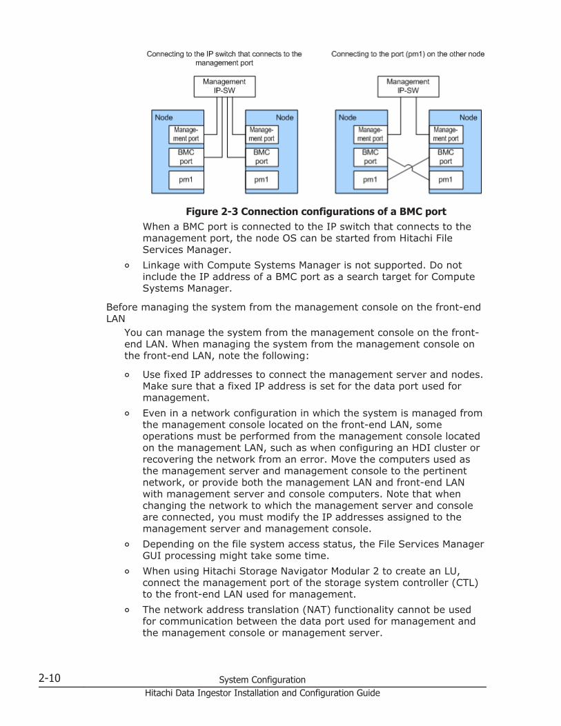
Figure 2-3 Connection configurations of a BMC portWhen a BMC port is connected to the IP switch that connects to themanagement port, the node OS can be started from Hitachi FileServices Manager.
¢ Linkage with Compute Systems Manager is not supported. Do notinclude the IP address of a BMC port as a search target for ComputeSystems Manager.
Before managing the system from the management console on the front-endLAN
You can manage the system from the management console on the front-end LAN. When managing the system from the management console onthe front-end LAN, note the following:
¢ Use fixed IP addresses to connect the management server and nodes.Make sure that a fixed IP address is set for the data port used formanagement.
¢ Even in a network configuration in which the system is managed fromthe management console located on the front-end LAN, someoperations must be performed from the management console locatedon the management LAN, such as when configuring an HDI cluster orrecovering the network from an error. Move the computers used asthe management server and management console to the pertinentnetwork, or provide both the management LAN and front-end LANwith management server and console computers. Note that whenchanging the network to which the management server and consoleare connected, you must modify the IP addresses assigned to themanagement server and management console.
¢ Depending on the file system access status, the File Services ManagerGUI processing might take some time.
¢ When using Hitachi Storage Navigator Modular 2 to create an LU,connect the management port of the storage system controller (CTL)to the front-end LAN used for management.
¢ The network address translation (NAT) functionality cannot be usedfor communication between the data port used for management andthe management console or management server.
2-10 System ConfigurationHitachi Data Ingestor Installation and Configuration Guide

¢ When changing settings for the data port used for management,perform the operation from the management console in themanagement LAN. If you change a data port setting from amanagement console in the front-end LAN, the GUI might becomeunable to respond. If this problem occurs, click the X button on thetitle bar to close the window.
¢ If you specify an incorrect setting when trunking the data port usedfor management, you might be unable to use the File ServicesManager GUI from the management console in the front-end LAN. Thesystem administrator must retry network setup from the managementconsole in the management LAN.
¢ For Hitachi AMS2000 series storage or HUS100 series, you cannotcreate a VLAN interface for the data port that will be used formanagement.
¢ When updating the software, perform the operation from themanagement console located on the management LAN.
Note that if the following setting tasks have yet to be completed at thetime of system implementation, you must perform these tasks from themanagement console located on the management LAN:
¢ Defining the HDI cluster configuration
¢ Setting the data portsConfigure the network so that the management server and managementconsole can be used from the management LAN. After completing thenecessary settings, change the network configuration so that themanagement server and management console can be used from thefront-end LAN, and then start operation.In addition, the following error recovery actions must be performed fromthe management console located on the management LAN:
¢ Recovering the front-end LAN from a network error
¢ Recovering a data port from a link error
¢ Restoring saved system LU informationYou also need to perform operations from the management consolelocated on the management LAN when you are instructed to operate theclusters by the maintenance personnel for error recovery. Change thenetwork configuration so that the management server and managementconsole that have been used from the front-end LAN can be used fromthe management LAN. After the necessary recovery action is completed,restore the network configuration so that the management server andmanagement console can be used from the front-end LAN, and thenresume operation.
Network configuration required to use CIFS sharesIf CIFS shares are to be used, both the nodes within a cluster must belong tothe same workgroup, NT domain, or Active Directory domain.
System Configuration 2-11Hitachi Data Ingestor Installation and Configuration Guide

CIFS clients specify the virtual IP address of a node or use the nameresolution service to access CIFS shares.
CIFS clients can also use a browser to access CIFS shares. Notes for using abrowser are as follows:
• When configuring a network, make sure that names are resolvable usinga service such as DNS, WINS, or lmhosts.
• The system must be configured in the CIFS Service Management page(Setting Type: Security) so that it accepts access requests from CIFSclients using NetBIOS over the TCP/IP protocol. If not, the followingproblems occur:
¢ The CIFS service of the HDI system does not work as a local masterbrowser.
¢ The CIFS service of the HDI system is not displayed in the list ofcomputers on the CIFS client.
¢ Names cannot be resolved by using a broadcast from a CIFS client inthe same subnet.
• Whenever you start or stop a domain controller placed on the samesubnet, the system attempts to select a local master browser (for about12 minutes). If no domain controller exists on the same subnet and thesystem attempts to restart a local master browser, the process ofselecting a local master browser or acquiring computer information willtake a long time. The CIFS client cannot access CIFS shares until the localmaster browser starts.
• A list of computers displayed on the CIFS client is based on informationthat is provided by a local master browser, and it does not correspond tothe operational status of each computer. Therefore, the CIFS clientcannot access a stopped computer, even though the computer exists inthe list of computers.
The following describes the network configuration when using the browsingfunctionality.
When the CIFS client and the node are connected to the same subnet
If the CIFS client and the node are connected to the same subnet, werecommend that you use the WINS server on the CIFS client side to resolvecomputer names.
If a domain controller does not exist in the same subnet, the CIFS service ofthe HDI system might work as a local master browser. In such a case, theCIFS service that works as a local master browser temporarily stops when afailover occurs. Because of this temporary stop, the CIFS client will takelonger to acquire a list of computers. When the CIFS client access CIFSshares, the CIFS service must have worked as a local master browser.
The following figure illustrates a network where the CIFS client and the nodebelong to a single work group.
2-12 System ConfigurationHitachi Data Ingestor Installation and Configuration Guide

Figure 2-4 Network where the CIFS client and the node belong to a singlework group
The following figure illustrates a network where the CIFS client and the nodebelong to multiple work groups.
Figure 2-5 Network where the CIFS client and the node belong to multiplework groups
The following figure illustrates a network where the CIFS client and the nodebelong to a single NT domain.
System Configuration 2-13Hitachi Data Ingestor Installation and Configuration Guide

Figure 2-6 Network where the CIFS client and the node belong to a singleNT domain
When the CIFS client and the node are connected to different subnets
When the CIFS client and the node are connected to different subnets, notethe following points:
• An NT domain configuration or Active Directory domain configuration isrequired.
• A domain controller is required for the subnet to which the node isconnected.
• If a WINS server is used as a name server to CIFS clients, we recommendthat all the CIFS clients in the network be set as WINS clients.
• If a WINS server is not used, the lmhosts file must be modified asfollows:
In an NT domain configurationAdd the following entry to the lmhosts file in the backup domaincontroller. When you use the subnet not connecting with the domaincontroller, add the following entry to the lmhosts file provided foreach CIFS client.IP-address-of-the-primary-domain-controller domain-name#1B
In an Active Directory domain configurationAdd the following entry to the lmhosts file in the domain controllerthat exists in the same subnet as the CIFS client. In the subnet wherethe domain controller is not connected, add the following entry to thelmhosts file provided for each CIFS client.IP-address-of-the-domain-controller-that-exists-in-the-same-subnet-as-the-node#1B
In an NT domain configuration, the following figure illustrates a networkwhere the node and the primary domain controller exist in the same subnet.
2-14 System ConfigurationHitachi Data Ingestor Installation and Configuration Guide

Figure 2-7 Network where the node and the primary domain controllerexist in the same subnet (NT domain configuration)
The figure below shows an example of a network in an NT domainconfiguration in which the nodes and the primary domain controller areplaced on different subnets.
Figure 2-8 Network where the nodes and the primary domain controllerare placed on different subnets (NT domain configuration)
In an Active Directory domain configuration, the following figure illustrates anetwork where the node and the primary domain controller exist in the samesubnet.
System Configuration 2-15Hitachi Data Ingestor Installation and Configuration Guide

Figure 2-9 Network where the node and the primary domain controllerexist in the same subnet (Active Directory domain configuration)
When the CIFS service is used with multiple ports
When the CIFS service is used with multiple ports, a separate WINS server isnecessary for each subnet to which each port is connected. All the CIFSclients connected to the network can select an access path to the node for theHDI system according to the used WINS servers.
2-16 System ConfigurationHitachi Data Ingestor Installation and Configuration Guide
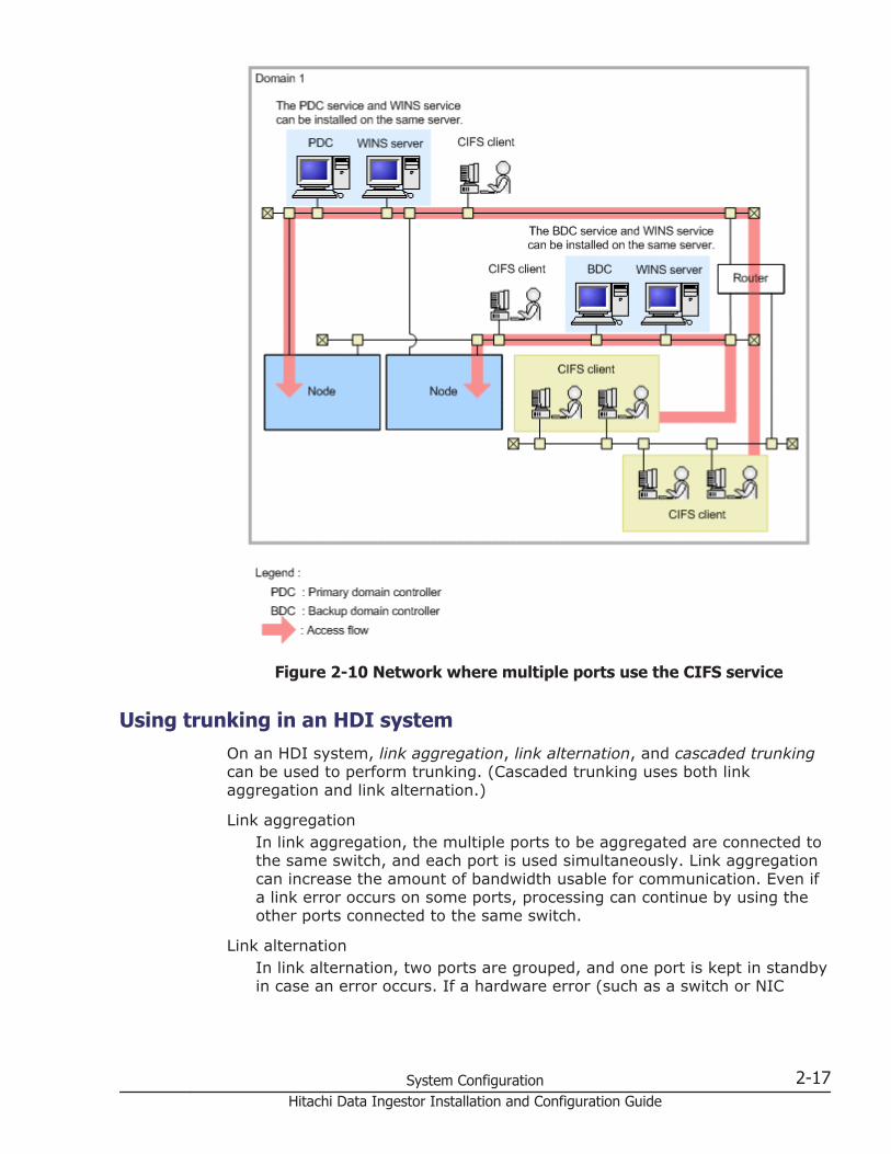
Figure 2-10 Network where multiple ports use the CIFS service
Using trunking in an HDI systemOn an HDI system, link aggregation, link alternation, and cascaded trunkingcan be used to perform trunking. (Cascaded trunking uses both linkaggregation and link alternation.)
Link aggregationIn link aggregation, the multiple ports to be aggregated are connected tothe same switch, and each port is used simultaneously. Link aggregationcan increase the amount of bandwidth usable for communication. Even ifa link error occurs on some ports, processing can continue by using theother ports connected to the same switch.
Link alternationIn link alternation, two ports are grouped, and one port is kept in standbyin case an error occurs. If a hardware error (such as a switch or NIC
System Configuration 2-17Hitachi Data Ingestor Installation and Configuration Guide
error) does occur, the ports are switched automatically, and processingcan continue by using the standby port.
Cascaded trunkingIn cascaded trunking, link alternation is set for two ports, including atleast one virtual port configured by using link aggregation. Since thecombination of link aggregation and link alternation can handle both linkerrors and hardware errors, we recommend using cascaded trunking toconfigure networks on an HDI system. When using cascaded trunking,always use it together with a tagged VLAN to stabilize communicationbetween the client and an HDI system.
This subsection describes recommended network configurations for thetrunking functionality available on HDI systems.
Features
By using trunking in the HDI system, you can achieve the following:
• If all physical ports connected to the network are trunked, failover can beavoided when some of the ports encounter a link error (note that afailover will occur if all the ports encounter a link error).
• You can simultaneously use multiple physical ports grouped by linkaggregation to increase the communication speed of these ports as asingle interface.
• Because IP addresses are assigned to trunked virtual ports, the numberof IP addresses you need to manage is smaller than when IP addressesare assigned to all physical ports.
• Trunking and a VLAN can be used together. Always use a VLAN togetherwith trunking when using cascaded trunking. To use both a VLAN andtrunking, see Using both a VLAN and trunking in an HDI system on page2-24.
Trunking prerequisites
Before using trunking, verify the following:
• Ports with different media types cannot be trunked. Trunking must onlybe configured on ports whose media types are identical.
• Ports with different Ethernet standards cannot be trunked. Trunking mustonly be configured on ports with the same Ethernet standard, such asGigabit Ethernet or 10 Gigabit Ethernet.
• Before using trunking, you must configure the network environment towhich nodes are connected (specify switch settings, for example).
• To use link aggregation, the switches to be used must comply withIEEE802.3ad (Dynamic LACP). Set the LACP mode to Active.
• Depending on the types of switches to which the nodes are connected,the number of ports eligible for link aggregation might be limited. Fordetails on the maximum number of ports that can be link aggregated, seethe documentation for the switch being used.
2-18 System ConfigurationHitachi Data Ingestor Installation and Configuration Guide

• The switches that are connected to the nodes include a switch thatprovides a Port Fast/Uplink Fast (or Fast-forwarding) functionality, whichis an extension of STP (Spanning Tree Protocol). For continuous operationof the HDI system, we recommend that you enable the Port Fast/UplinkFast functionality for node ports directly connected to the front-end LAN.
• A failover will occur if a failure occurs on a non-trunked node port. As aresult, we recommend that you use trunking for all ports.
• On an HDI system, link alternation cannot be set for three ports or more.
• Before using a trunk port, make sure that the appropriate negotiationmode is set for the port. If the negotiation mode is changed when theport is running, communication via the port might be stoppedtemporarily.
Recommended trunking configurations
If link aggregation is enabled, in the event of a link error on some ports,processing can continue by using other ports connected to the same switch.If link alternation is enabled, in the event of a hardware error in the switch orNIC hardware, the port will be automatically switched to a standby port tocontinue processing.
For an HDI system, we recommend that you configure the network usingcascaded trunking to ensure that operation can continue even when a linkerror or hardware error occurs. You should also trunk all ports. This isbecause if the node contains a port that is not trunked, an error on thatuntrunked port will cause a failover.
For an HDI system, we recommend that you configure cascaded trunking sothat the node that is running will have higher performance than the standbynode. Note, however, that a too-large difference in performance between theexecuting and standby nodes might affect operation because the systemperformance drastically drops upon changeover to the standby port.Configure the network so that the standby node will maintain the minimumperformance required to continue processing.
The following figure illustrates an example of the cascaded trunkingconfiguration recommended for an HDI system.
Figure 2-11 Example cascaded trunking configuration recommended for anHDI system
The HDI system does not support the following trunking configurations:
• Link alternation set among three or more ports.
System Configuration 2-19Hitachi Data Ingestor Installation and Configuration Guide

• Trunking set for a link alternation port.
• Link aggregation set for a link aggregation port.
Examples of a network configuration
The following are examples of a network configuration when cascadedtrunking is used.
Figure 2-12 Example of a network configuration when cascaded trunkingis used (when no error has occurred)
2-20 System ConfigurationHitachi Data Ingestor Installation and Configuration Guide

Figure 2-13 Example of a network configuration when cascaded trunkingis used (when a link error has occurred)
System Configuration 2-21Hitachi Data Ingestor Installation and Configuration Guide

Figure 2-14 Example of a network configuration when cascaded trunkingis used (when a hardware error has occurred)
Using a VLAN in an HDI systemHDI systems allow you to use VLANs to configure a network. This subsectionoutlines VLANs available in an HDI system.
Features
The following describes the features for when a VLAN is used in an HDIsystem:
• An IEEE802.1Q tagged VLAN can be used.
• Even if a network is configured using a VLAN, in the event of an error in anode, you can perform maintenance work such as error recovery orreplacement while the service continues to be provided by a failover.
2-22 System ConfigurationHitachi Data Ingestor Installation and Configuration Guide

• You can set an MTU value (the maximum value of data that can betransmitted for each transfer operation in the communication network) foreach VLAN.
VLAN prerequisites
To use a VLAN in an HDI system, a switch supporting an IEEE802.1Q taggedVLAN is required.
VLAN interface setting
When a VLAN is used, a virtual interface (a VLAN interface) is created for thedata port. An identifier called a VLAN ID must be assigned to the VLANinterface.
Also, a virtual IP address can be set for the VLAN interface so that theresource group can be connected using the same IP address during failover.To detect an error such as a link down in both nodes, we recommend thatyou specify a virtual IP address for both nodes. If you do not specify a virtualIP address, you must check the system message in the List of RASInformation page (for List of messages) of the Check for Errors dialogbox.
The following describes the number and range of specifiable VLAN IDs percluster and the number of virtual IP addresses:
Number of VLAN IDsYou can set a maximum of 256 VLAN IDs per cluster. When the numberof virtual IP addresses reaches the maximum (256 per cluster), youcannot set any more VLAN IDs.
Range of VLAN IDsYou can set VLAN IDs from 1 to 4094. VLAN IDs must not be duplicatedwithin a cluster.
Number of virtual IP addressesYou can set a maximum of 256 virtual IP addresses per cluster.
Example network configurations
The following shows an example of a network configuration when a VLAN isused.
System Configuration 2-23Hitachi Data Ingestor Installation and Configuration Guide
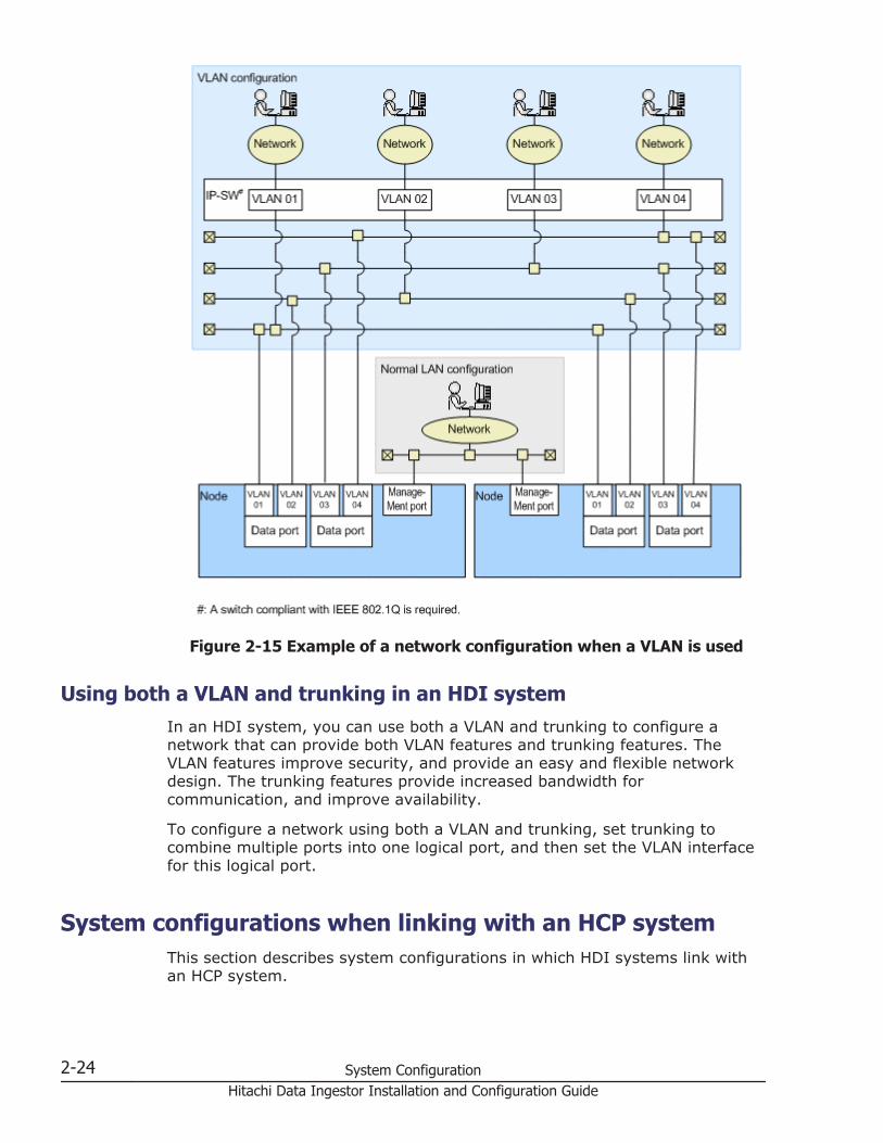
Figure 2-15 Example of a network configuration when a VLAN is used
Using both a VLAN and trunking in an HDI systemIn an HDI system, you can use both a VLAN and trunking to configure anetwork that can provide both VLAN features and trunking features. TheVLAN features improve security, and provide an easy and flexible networkdesign. The trunking features provide increased bandwidth forcommunication, and improve availability.
To configure a network using both a VLAN and trunking, set trunking tocombine multiple ports into one logical port, and then set the VLAN interfacefor this logical port.
System configurations when linking with an HCP systemThis section describes system configurations in which HDI systems link withan HCP system.
2-24 System ConfigurationHitachi Data Ingestor Installation and Configuration Guide

We recommend that you use the NTP server in order to synchronize the timesbetween the HCP system and the individual devices of the HDI system.
Linking to an HCP system that shares the same storage systemThe following figure shows a configuration example of an HDI system thatlinks with an HCP system that shares the same storage system.
Figure 2-16 Configuration example of an HDI system linking with an HCPsystem that shares the same storage system
The following conditions must be satisfied to link an HDI system with an HCPsystem that shares the same storage system:
• Connect the HDI and HCP ports that are used for client data access to thefront-end LAN.
System Configuration 2-25Hitachi Data Ingestor Installation and Configuration Guide

• A router is placed between the management LAN and the front-end LANso that the HCP system on the front-end LAN can communicate with amanagement console on the management LAN by using http or https. Inaddition, if you place an external server on the front-end LAN, specify, asnecessary, the settings so that the external server and the managementserver can communicate.
• The DNS server is placed on the front-end LAN.
• The HCP system that links with the HDI system has a minimumconfiguration (basic configuration) of 4 nodes and can use up to 16nodes.
• If you use the HCP GUI on the HDI management console, a DNS serverthat can resolve the names for the HCP system must be registered in themanagement console.
When linkage is made via a networkThe following figure shows a configuration example of HDI systems that linkwith an HCP system via a network (WAN) by using Network AddressTranslation (NAT) functionality or Virtual Private Network (VPN) functionality.
2-26 System ConfigurationHitachi Data Ingestor Installation and Configuration Guide
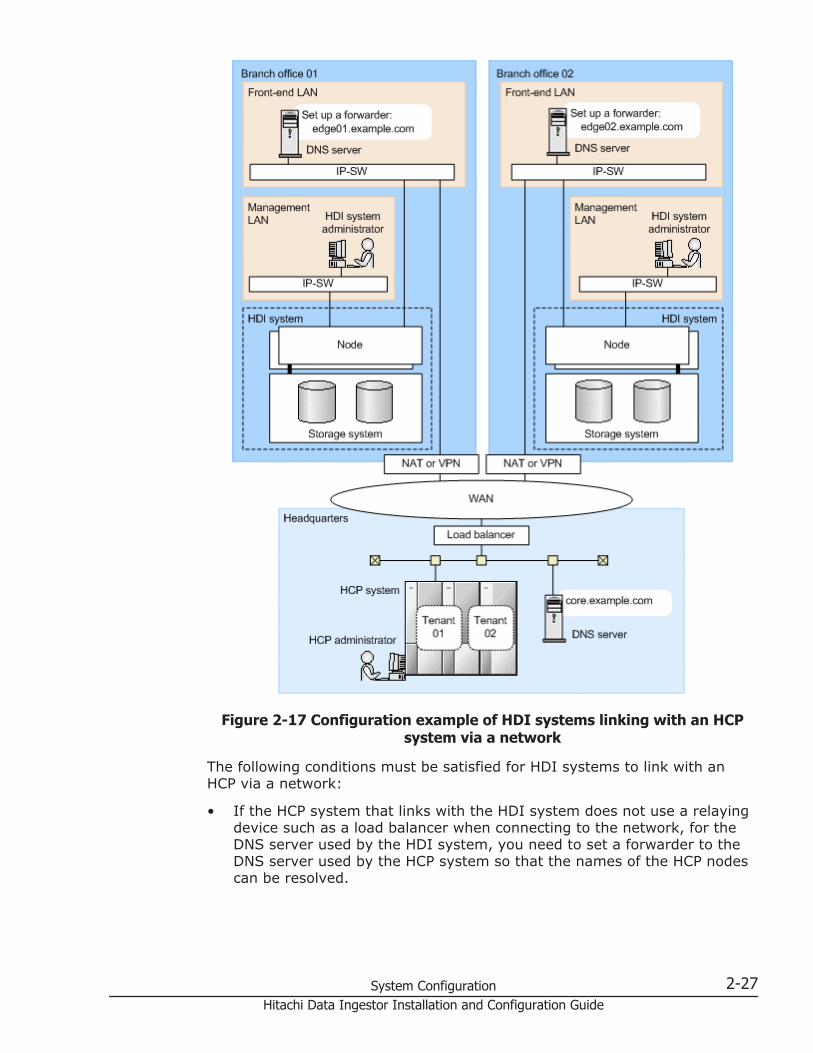
Figure 2-17 Configuration example of HDI systems linking with an HCPsystem via a network
The following conditions must be satisfied for HDI systems to link with anHCP via a network:
• If the HCP system that links with the HDI system does not use a relayingdevice such as a load balancer when connecting to the network, for theDNS server used by the HDI system, you need to set a forwarder to theDNS server used by the HCP system so that the names of the HCP nodescan be resolved.
System Configuration 2-27Hitachi Data Ingestor Installation and Configuration Guide

If the HCP system that links with the HDI system uses a relaying device,you need to specify settings so that the HDI system can communicatewith the HCP system via the relaying device.
• Ask the HCP administrator to create tenants to be used by the HDIsystem.
• The HCP system that links with the HDI system has a minimumconfiguration (basic configuration) of 4 nodes and can use up to 16nodes.
The settings required for an HCP system that links with the HDI system areas follows:
• If the HCP system that links with the HDI system uses a relaying devicewhen connecting to the network, round-robin DNS cannot be used forload balancing. Use a load balancer or another device for balancing theload as necessary.
• Relaying devices used when an HCP system connects to a network, suchas a load balancer, need to be configured to meet the followingconditions:
¢ The device can communicate with the port used to connect to an HCPsystem (80 or 9090 for HTTP, 443 or 9090 for HTTPS).
¢ The device can transfer the Host header of an HTTP request withoutconverting it.
¢ The device can use chunked transfer encoding.
¢ When the file compression function is enabled for communicationswith an HCP system, gzip can be specified in the Accept-Encodingheader.
¢ When SSL is enabled, HTTPS communications can be relayed.
2-28 System ConfigurationHitachi Data Ingestor Installation and Configuration Guide
3Environment Settings for External
Servers
To run and manage an HDI system, you must provide several externalservers on the network.
This chapter describes the environment settings for these external servers.
□ External servers required in an HDI system
□ Environment settings for a management server
□ Environment settings for a management console
□ Environment settings for the NIS server
□ Environment settings for the LDAP server
□ Environment settings for the domain controller
□ Environment settings for the KDC server
□ Environment settings for the RADIUS server
□ Environment settings for the SNMP manager
□ Environment settings for the NTP server
□ Environment settings for the scan server
□ Environment settings for a tape device connected to a node via a SAN
□ SMTP server environment settings
Environment Settings for External Servers 3-1Hitachi Data Ingestor Installation and Configuration Guide

□ DHCP server environment settings
□ DNS server environment settings
3-2 Environment Settings for External ServersHitachi Data Ingestor Installation and Configuration Guide

External servers required in an HDI systemThe following table summarizes the external servers required in an HDIsystem.
Table 3-1 External servers required in an HDI system
Externalserver Description Settings for linkage with
an HDI system
DHCP server A DHCP server is required in a single-nodeconfiguration to set network informationsuch as the IP address or the defaultgateway of a node using DHCP.
None
DNS server A DNS server is required for searching forhost names via the DNS.
IP address
FTP server An FTP server is required for downloadingdump files, and all log files. A destinationdirectory must be created for the transfer.
• IP address or host name
• User name andpassword
• Destination directory
KDC server A KDC server is required for authenticatingusers by using Kerberos authentication withthe NFS service.
• Server name
• Domain name
LDAP server An LDAP server is required for managinguser information on the LDAP server.
The LDAP server for user authentication canalso be used as a server for NFSv4 domainID mapping.
• IP address or host name
• Port number
• Route ID name (in DNformat)
• Administrator name (inDN format) andpassword
An LDAP server is also required for storinginformation about automatically assigneduser IDs and group IDs in the database onthe LDAP server.
• IP address or host name
• Port number
• Route ID name (in DNformat)
• ID name for adding auser mapping account(in DN format)
• Administrator name (inDN format) andpassword
NIS server An NIS server is required to search userand host information via the NIS.
• Domain name
• IP address or host name(when a specific serveris to be used)
NTP server An NTP server is required for ensuring thecorrect time on physical nodes.
IP address or host name
SNMPmanager
An SNMP server is required for viewingsystem information and receiving failurereports. Note that an SNMP manager mustbe connected to the management LAN.
If SNMPv2 will be used:
• Community name
Environment Settings for External Servers 3-3Hitachi Data Ingestor Installation and Configuration Guide
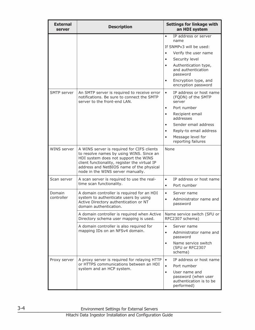
Externalserver Description Settings for linkage with
an HDI system
• IP address or servername
If SNMPv3 will be used:
• Verify the user name
• Security level
• Authentication type,and authenticationpassword
• Encryption type, andencryption password
SMTP server An SMTP server is required to receive errornotifications. Be sure to connect the SMTPserver to the front-end LAN.
• IP address or host name(FQDN) of the SMTPserver
• Port number
• Recipient emailaddresses
• Sender email address
• Reply-to email address
• Message level forreporting failures
WINS server A WINS server is required for CIFS clientsto resolve names by using WINS. Since anHDI system does not support the WINSclient functionality, register the virtual IPaddress and NetBIOS name of the physicalnode in the WINS server manually.
None
Scan server A scan server is required to use the real-time scan functionality.
• IP address or host name
• Port number
Domaincontroller
A domain controller is required for an HDIsystem to authenticate users by usingActive Directory authentication or NTdomain authentication.
• Server name
• Administrator name andpassword
A domain controller is required when ActiveDirectory schema user mapping is used.
Name service switch (SFU orRFC2307 schema)
A domain controller is also required formapping IDs on an NFSv4 domain.
• Server name
• Administrator name andpassword
• Name service switch(SFU or RFC2307schema)
Proxy server A proxy server is required for relaying HTTPor HTTPS communications between an HDIsystem and an HCP system.
• IP address or host name
• Port number
• User name andpassword (when userauthentication is to beperformed)
3-4 Environment Settings for External ServersHitachi Data Ingestor Installation and Configuration Guide

Externalserver Description Settings for linkage with
an HDI system
Managementconsole
A management console is a computer thatis needed to use HDI commands or its GUI.
None
Managementserver
A management server is a computer onwhich Hitachi File Services Manager hasbeen installed. A management server canalso be used as a management console.
None
Relayingdevices usedby an HCPsystem to belinked (suchas a loadbalancer)
A relaying device (such as a load balancer)is required for HTTP or HTTPScommunications between an HDI systemand an HCP system.
IP address or host name
Environment settings for a management serverThis section describes the environment settings for a management server.
Requirements for a management serverThe following table summarizes the requirements for a management server.
Table 3-2 Requirements for a management server
Item Requirement
Applicable OSs • Microsoft(R) Windows(R) 7 Enterprise (without any SP orwith SP1)
• Microsoft(R) Windows(R) 7 Enterprise x64 Edition (withoutany SP or with SP1)
• Microsoft(R) Windows(R) 7 Professional (without any SP orwith SP1)
• Microsoft(R) Windows(R) 7 Professional x64 Edition (withoutany SP or with SP1)
• Microsoft(R) Windows(R) 7 Ultimate (without any SP or withSP1)
• Microsoft(R) Windows(R) 7 Ultimate x64 Edition (without anySP or with SP1)
• Microsoft(R) Windows(R) 8 32-bit#1
• Microsoft(R) Windows(R) 8 64-bit#1
• Microsoft(R) Windows(R) 8 Enterprise 32-bit#1
• Microsoft(R) Windows(R) 8 Enterprise 64-bit#1
• Microsoft(R) Windows(R) 8 Pro 32-bit#1
• Microsoft(R) Windows(R) 8 Pro 64-bit#1
Environment Settings for External Servers 3-5Hitachi Data Ingestor Installation and Configuration Guide

Item Requirement
• Microsoft(R) Windows(R) Vista Business 32-bit (with SP1 orSP2)
• Microsoft(R) Windows(R) Vista Business 64-bit (with SP1 orSP2)
• Microsoft(R) Windows(R) Vista Enterprise 32-bit (with SP1 orSP2)
• Microsoft(R) Windows(R) Vista Enterprise 64-bit (with SP1 orSP2)
• Microsoft(R) Windows(R) Vista Ultimate 32-bit (with SP1 orSP2)
• Microsoft(R) Windows(R) Vista Ultimate 64-bit (with SP1 orSP2)
• Microsoft(R) Windows Server(R) 2003, Datacenter Edition(with SP1 or SP2)
• Microsoft(R) Windows Server(R) 2003, Datacenter x64Edition (with SP1 or SP2)
• Microsoft(R) Windows Server(R) 2003, Enterprise Edition(with SP1 or SP2)
• Microsoft(R) Windows Server(R) 2003, Enterprise x64Edition (with SP1 or SP2)
• Microsoft(R) Windows Server(R) 2003, Standard Edition(with SP1 or SP2)
• Microsoft(R) Windows Server(R) 2003, Standard x64 Edition(with SP1 or SP2)
• Microsoft(R) Windows Server(R) 2003 R2, Datacenter Edition(without any SP or with SP2)
• Microsoft(R) Windows Server(R) 2003 R2, Datacenter x64Edition (without any SP or with SP2)
• Microsoft(R) Windows Server(R) 2003 R2, Enterprise Edition(without any SP or with SP2)
• Microsoft(R) Windows Server(R) 2003 R2, Enterprise x64Edition (without any SP or with SP2)
• Microsoft(R) Windows Server(R) 2003 R2, Standard Edition(without any SP or with SP2)
• Microsoft(R) Windows Server(R) 2003 R2, Standard x64Edition (without any SP or with SP2)
• Microsoft(R) Windows Server(R) 2008 Datacenter 32-bit(with SP1 or SP2)
• Microsoft(R) Windows Server(R) 2008 Datacenter 64-bit(with SP1 or SP2)
• Microsoft(R) Windows Server(R) 2008 Enterprise 32-bit(with SP1 or SP2)
• Microsoft(R) Windows Server(R) 2008 Enterprise 64-bit(with SP1 or SP2)
• Microsoft(R) Windows Server(R) 2008 Standard 32-bit (withSP1 or SP2)
• Microsoft(R) Windows Server(R) 2008 Standard 64-bit (withSP1 or SP2)
3-6 Environment Settings for External ServersHitachi Data Ingestor Installation and Configuration Guide

Item Requirement
• Microsoft(R) Windows Server(R) 2008 R2 Datacenter(without any SP or with SP1)
• Microsoft(R) Windows Server(R) 2008 R2 Enterprise (withoutany SP or with SP1)
• Microsoft(R) Windows Server(R) 2008 R2 Standard (withoutany SP or with SP1)
• Microsoft(R) Windows Server(R) 2012 Datacenter#1
• Microsoft(R) Windows Server(R) 2012 Standard#1
• Microsoft(R) Windows Server(R) 2012 R2 Datacenter#1#2
• Microsoft(R) Windows Server(R) 2012 R2 Standard#1#2
CPU Minimum configuration:
Dual-core processor
Recommended configuration:
Quad-core or better processor
Memory Minimum
2 GB
Recommended
At least 4 GB#3
Disk space Minimum
4 GB
Recommended
At least 5 GB
LAN card 10/100 Ethernet LAN card
If the computer and the LAN cable are compatible with GigabitEthernet, you can use a Gigabit-class card.
DVD-ROM drive Required
#1:Both Modern UI and Desktop are available for the user interface. UseDesktop.
#2:You cannot encrypt communications between the management server andclients by performing the procedure in Configuring SSL on page 7-91.
#3:If other software products are used simultaneously, the memoryrequirements of all of the software products must be taken into account.
If there is not enough virtual memory on the management server, programoperations might become unstable, or programs might not be able to start.To stably operate Hitachi File Services Manager, virtual memory that meetsthe following conditions is required in addition to the virtual memory that isused by the OS and other programs.
Environment Settings for External Servers 3-7Hitachi Data Ingestor Installation and Configuration Guide

Table 3-3 Virtual memory requirement for Hitachi File Services Manager
Program Virtual memory (MB)
Hitachi File ServicesManager
1,024
Hitachi Command SuiteCommon Component
When the memory heap sizein Hitachi Command SuiteCommon Component is setto Small
1,524
When the memory heap sizein Hitachi Command SuiteCommon Component is setto Medium
1,780
When the memory heap sizein Hitachi Command SuiteCommon Component is setto Large
2,292
If Hitachi Command Suite products are installed on the management server,virtual memory space for those products is also required. The table belowlists the recommended amount of virtual memory for each Hitachi CommandSuite product as of version 7.6.0. Secure virtual memory that is larger thanthe total of these sizes.
Table 3-4 Recommended amount of virtual memory for Hitachi CommandSuite products
Product Virtual memory (MB)
Hitachi Command Suite#1
• Device Manager
• Tiered Storage Manager
• Replication Manager
• Host Data Collector
If the memory heap size in DeviceManager is set to Small
3,300
If the memory heap size in DeviceManager is set to Medium
3,500
If the memory heap size in DeviceManager is set to Large
3,900
Tuning Manager 1,500
Global Link Manager 300
Compute Systems Manager 2,500
Hitachi Storage Navigator Modular2#2
200
#1Device Manager, Tiered Storage Manager, Replication Manager, and HostData Collector are always installed together.
#2
3-8 Environment Settings for External ServersHitachi Data Ingestor Installation and Configuration Guide

The required virtual memory size for Hitachi Storage Navigator Modular 2version 23.50 is assumed. For details on the latest virtual memory size,see the Hitachi Storage Navigator Modular 2 documentation.
Tip:
• If the Device Manager agent is installed on the management server,secure the virtual memory required for the Device Manager agent. To seta virtual memory size for Device Manager agent, use theserver.agent.maxMemorySize property. For details about this property,see the Hitachi Command Suite Software Installation and ConfigurationGuide.
• If Replication Manager Application Agent is installed on the managementserver, secure the virtual memory required for Replication ManagerApplication Agent. For the amount of virtual memory to be secured, seethe Hitachi Command Suite Replication Manager Software ConfigurationGuide.
• If the Tuning Manager series agents are installed on the managementserver, secure the virtual memory required for all agents. For the amountof virtual memory to be secured, see the explanation that describesmemory requirements in the applicable agent manual.
Management server cluster configurationManagement servers can be clustered in an active-standby configuration. In acluster, the server that is being used for operation is called the executingnode and the server that is standing by so that it can take over operation inthe event of an error on the executing node is called the standby node.
If an error occurs on the executing node, the cluster software detects this andswitches the executing node to the standby node (that is, the standby nodebecomes the executing node). This arrangement allows management serversto run continuously without interruption.
The following table lists applicable OSs and the required cluster softwarewhen the management servers are clustered.
Table 3-5 Applicable OSs and required cluster software for operatingmanagement servers in a cluster configuration
Applicable OSs Cluster software
Microsoft(R) Windows Server(R) 2003, EnterpriseEdition Operating System#
Microsoft Cluster Service
Microsoft(R) Windows Server(R) 2003 R2,Enterprise Edition#
Microsoft Cluster Service
Microsoft(R) Windows Server(R) 2008 EnterpriseEdition Operating System
Microsoft Failover Cluster
Microsoft(R) Windows Server(R) 2012 Datacenter
Microsoft(R) Windows Server(R) 2012 Standard
Microsoft Failover Cluster
Environment Settings for External Servers 3-9Hitachi Data Ingestor Installation and Configuration Guide

#:x86 is the only architecture that can be used.
Executing a command with administrative privileges from acommand prompt
When you use a Windows operating system that provides the UAC feature,such as Windows Vista, and the UAC feature is enabled, some commands canbe executed only by users who have administrative privileges. Unlessotherwise indicated, when you execute the commands described in themanual from the management server command prompt, you needadministrative privileges.
You can use either of the following methods to execute commands thatrequire administrative privileges. We recommend that you use the firstmethod so that you can view the results output to the command prompt.
1. Execute the command from an elevated command prompt. (This is therecommended method.)If you are using Windows 7 or an earlier Windows version, select andright-click the command prompt icon in the Start menu and choose Runas Administrator to open the elevated command prompt window.If you are using Windows 8 or Windows Server 2012, move the mousecursor to the lower-left corner of the desktop and right-click the smallStart screen. From the management menu, select Command Prompt(Admin) to open the elevated command prompt window.
2. Enter the command from an ordinary command prompt, and then consentto elevating your privileges in the message dialog box that appears.When you attempt to execute a command from an ordinary commandprompt, a message prompting you to elevate your privileges appears.Consent to this request.Note that, with this method, execution results are displayed in a newcommand prompt window rather than in the command prompt windowfrom which you executed the command. Also, the new window closesautomatically when the execution results have been displayed.If you choose not to elevate your privileges, the command is notexecuted, although a return code of 0 (for normal termination) isreturned.
Referential note:Performing one of the following operations from the Windows Start menu(or the application list in the Start menu of Windows 8 or Windows Server2012) also requires you to right-click the menu item icon and then chooseRun as Administrator.
3-10 Environment Settings for External ServersHitachi Data Ingestor Installation and Configuration Guide
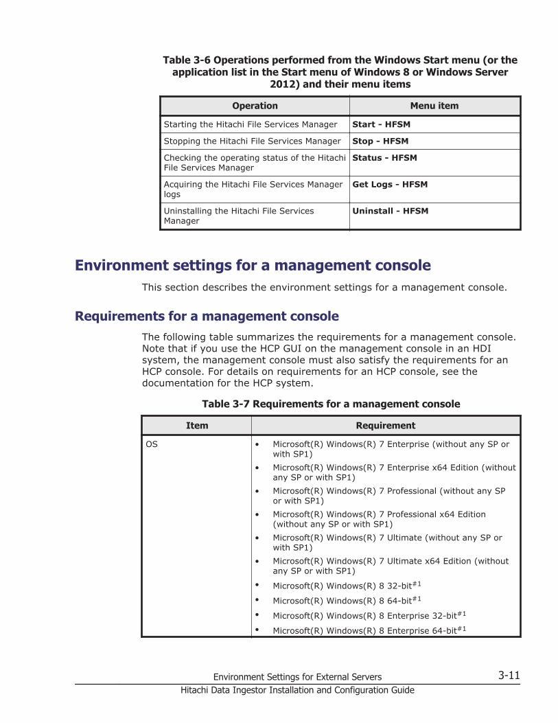
Table 3-6 Operations performed from the Windows Start menu (or theapplication list in the Start menu of Windows 8 or Windows Server
2012) and their menu items
Operation Menu item
Starting the Hitachi File Services Manager Start - HFSM
Stopping the Hitachi File Services Manager Stop - HFSM
Checking the operating status of the HitachiFile Services Manager
Status - HFSM
Acquiring the Hitachi File Services Managerlogs
Get Logs - HFSM
Uninstalling the Hitachi File ServicesManager
Uninstall - HFSM
Environment settings for a management consoleThis section describes the environment settings for a management console.
Requirements for a management consoleThe following table summarizes the requirements for a management console.Note that if you use the HCP GUI on the management console in an HDIsystem, the management console must also satisfy the requirements for anHCP console. For details on requirements for an HCP console, see thedocumentation for the HCP system.
Table 3-7 Requirements for a management console
Item Requirement
OS • Microsoft(R) Windows(R) 7 Enterprise (without any SP orwith SP1)
• Microsoft(R) Windows(R) 7 Enterprise x64 Edition (withoutany SP or with SP1)
• Microsoft(R) Windows(R) 7 Professional (without any SPor with SP1)
• Microsoft(R) Windows(R) 7 Professional x64 Edition(without any SP or with SP1)
• Microsoft(R) Windows(R) 7 Ultimate (without any SP orwith SP1)
• Microsoft(R) Windows(R) 7 Ultimate x64 Edition (withoutany SP or with SP1)
• Microsoft(R) Windows(R) 8 32-bit#1
• Microsoft(R) Windows(R) 8 64-bit#1
• Microsoft(R) Windows(R) 8 Enterprise 32-bit#1
• Microsoft(R) Windows(R) 8 Enterprise 64-bit#1
Environment Settings for External Servers 3-11Hitachi Data Ingestor Installation and Configuration Guide

Item Requirement
• Microsoft(R) Windows(R) 8 Pro 32-bit#1
• Microsoft(R) Windows(R) 8 Pro 64-bit#1
• Microsoft(R) Windows(R) 8.1 32-bit#1
• Microsoft(R) Windows(R) 8.1 64-bit#1
• Microsoft(R) Windows(R) 8.1 Enterprise 32-bit#1
• Microsoft(R) Windows(R) 8.1 Enterprise 64-bit#1
• Microsoft(R) Windows(R) 8.1 Pro 32-bit#1
• Microsoft(R) Windows(R) 8.1 Pro 64-bit#1
• Microsoft(R) Windows(R) Vista Business 32-bit (with SP1or SP2)
• Microsoft(R) Windows(R) Vista Business 64-bit (with SP1or SP2)
• Microsoft(R) Windows(R) Vista Enterprise 32-bit (with SP1or SP2)
• Microsoft(R) Windows(R) Vista Enterprise 64-bit (with SP1or SP2)
• Microsoft(R) Windows(R) Vista Ultimate 32-bit (with SP1or SP2)
• Microsoft(R) Windows(R) Vista Ultimate 64-bit (with SP1or SP2)
• Microsoft(R) Windows Server(R) 2003, Datacenter Edition(with SP1 or SP2)
• Microsoft(R) Windows Server(R) 2003, Datacenter x64Edition (with SP1 or SP2)
• Microsoft(R) Windows Server(R) 2003, Enterprise Edition(with SP1 or SP2)
• Microsoft(R) Windows Server(R) 2003, Enterprise x64Edition (with SP1 or SP2)
• Microsoft(R) Windows Server(R) 2003, Standard Edition(with SP1 or SP2)
• Microsoft(R) Windows Server(R) 2003, Standard x64Edition (with SP1 or SP2)
• Microsoft(R) Windows Server(R) 2003 R2, DatacenterEdition (without any SP or with SP2)
• Microsoft(R) Windows Server(R) 2003 R2, Datacenter x64Edition (without any SP or with SP2)
• Microsoft(R) Windows Server(R) 2003 R2, EnterpriseEdition (without any SP or with SP2)
• Microsoft(R) Windows Server(R) 2003 R2, Enterprise x64Edition (without any SP or with SP2)
• Microsoft(R) Windows Server(R) 2003 R2, StandardEdition (without any SP or with SP2)
• Microsoft(R) Windows Server(R) 2003 R2, Standard x64Edition (without any SP or with SP2)
• Microsoft(R) Windows Server(R) 2008 Datacenter 32-bit(with SP1 or SP2)
3-12 Environment Settings for External ServersHitachi Data Ingestor Installation and Configuration Guide

Item Requirement
• Microsoft(R) Windows Server(R) 2008 Datacenter 64-bit(with SP1 or SP2)
• Microsoft(R) Windows Server(R) 2008 Enterprise 32-bit(with SP1 or SP2)
• Microsoft(R) Windows Server(R) 2008 Enterprise 64-bit(with SP1 or SP2)
• Microsoft(R) Windows Server(R) 2008 Standard 32-bit(with SP1 or SP2)
• Microsoft(R) Windows Server(R) 2008 Standard 64-bit(with SP1 or SP2)
• Microsoft(R) Windows Server(R) 2008 R2 Datacenter(without any SP or with SP1)
• Microsoft(R) Windows Server(R) 2008 R2 Enterprise(without any SP or with SP1)
• Microsoft(R) Windows Server(R) 2008 R2 Standard(without any SP or with SP1)
• Microsoft(R) Windows Server(R) 2012 Datacenter#1
• Microsoft(R) Windows Server(R) 2012 Standard#1
• Microsoft(R) Windows Server(R) 2012 R2 Datacenter#1
• Microsoft(R) Windows Server(R) 2012 R2 Standard#1
• Red Hat Enterprise Linux(R) 5.6#2
• Red Hat Enterprise Linux(R) 5.6 Advanced Platform#2
• Red Hat Enterprise Linux(R) 6.4#2
Memory At least 512 MB
CPU Any CPU recommended for the OS installed on themanagement console
Monitor resolution At least 1,024 x 768 pixels
Monitor display colors 16,777,216 colors (True color, 32-bit) or higher
Web browser#3 Any of the following Web browsers:
• Internet Explorer 7.0 (32-bit version)
• Internet Explorer 8.0 (32-bit version)
• Internet Explorer 9.0 (32-bit version)
• Internet Explorer 10.0 (32-bit desktop version)
• Internet Explorer 11.0#4 (32-bit desktop version)
• Firefox 3.6.x#5 (If the architecture is x86, and the OS isRed Hat Enterprise Linux(R))
• Firefox ESR 10.0.x#5 (If the architecture is x86, and theOS is Red Hat Enterprise Linux(R))
• Firefox ESR 17.0.x#5 (If the architecture is x86, and theOS is Red Hat Enterprise Linux(R))
• Firefox ESR 24.1.x#5 (If the architecture is x86, and theOS is Red Hat Enterprise Linux(R))
Environment Settings for External Servers 3-13Hitachi Data Ingestor Installation and Configuration Guide

Item Requirement
• Firefox ESR 31.0.x#5 (When managing HDI systems in asingle-node configuration)
Also, if you are managing an HDI system in a single-nodeconfiguration, install Adobe(R) Flash(R) Player 10.1 or later inthe web browser.
#1:Both Modern UI and Desktop are available for the user interface. UseDesktop.
#2:Logging on to the system in a single-node configuration using UPnP(Universal Plug and Play) is unavailable.
#3:Certain Web browser requirements must be met to view the HitachiStorage Navigator Modular 2 GUI from Hitachi Files Systems Manager. Fordetails about compatible Web browsers, see the Hitachi Storage NavigatorModular 2 documentation.
#4:When Internet Explorer 11.0 is used, if you click a button or anchor onthe screen to open a new tab or new window, an extra blank window ortransitional window might be displayed at the same time. In such a case,please close the unnecessary window.If such problems occur repeatedly, create a new Windows user account,and then use the new user account to operate the browser.
#5:x implies any digit. The final number in the version does not affectbrowser support.
Settings when Internet Explorer is used on the management consoleThis subsection describes the settings that must be configured when InternetExplorer is used. If you want to change the Web browser settings, close allbrowsers beforehand. Note that Internet Explorer 7.0 settings are used forthis subsection. For details on the settings when the version of InternetExplorer is not 7.0, see Internet Explorer Help.
Notes when using Internet Explorer
Note the following when using Internet Explorer:
• The tabbed browsing function cannot be used.
• Some dialog boxes might display a certificate error message or a securitywarning.Because an HDI system uses https communications between themanagement console and nodes, there is no problem even if a certificateerror message or a security warning is displayed.
3-14 Environment Settings for External ServersHitachi Data Ingestor Installation and Configuration Guide

• If you change the settings for displaying the menu bar, the settings mightnot be applied correctly.
• If you change the font size to larger or smaller, the GUI might not bedisplayed properly, and the scroll bar might not be displayed.
Internet Explorer settings
The following table shows the settings when using Internet Explorer. Foritems other than those indicated in the table, use the Internet Explorerdefault settings.
Table 3-8 Internet Explorer settings
Category Settings
Text Size Select Medium.
Using the cache#1 Select the Every time I visit the web page radiobutton.
Registering URLs as trustedsites zones#2
• Clear the Require server verification (https:) forall sites in this zone check box.
• In the Add this website to the zone text box, addthe management server URL, the URLs for allmanaged nodes, and about:internet.#3
Disabling the pop-upblocker#4
In the Address of website to allow text box, add themanagement server URL and the URLs for all managednodes.#3
Disabling downloadmonitoring#5
• Enable File download.
• When Internet Explorer 7.0 or Internet Explorer 8.0is used, enable Automatic prompting for filedownloads.
• Clear the Do not save encrypted pages to diskcheck box.
Verifying security settings • Enable Run Active X controls and plug-ins.
• Enable Script Active X controls marked safe forscripting.
• Enable Active scripting.
• Enable Launching programs and files in anIFRAME or specify Prompt.
• Enable Submit non-encrypted form data orspecify Prompt.
Enabling animations Select the Play animations in web pages check box.
Setting the proxy#6 If a proxy server is used, add the addresses of themanagement server and all the management-targetnodes to the Exceptions text box in the Proxy Settingsdialog box.
Setting tabbed browsing Select a radio button other than Always open pop-upsin a new tab.
Environment Settings for External Servers 3-15Hitachi Data Ingestor Installation and Configuration Guide

Category Settings
Setting the enhancedprotected mode
Clear the Enable Enhanced Protected Mode check box(when using Internet Explorer 10.0 or later).
#1:If you incorrectly use the cache, an old version of the GUI might bedisplayed, or the GUI might freeze when File Services Manager or aprogram that runs on a node is upgraded.
#2:If the Internet Explorer security enhancement configuration function isenabled, the operations available from the GUI might become limited.In this case, register the URLs of the management server, all themanaged nodes, and about:internet into the trusted sites zone of theInternet Explorer security zone.
#3:Use the following URL format:
¢ Management server URL:http://management-server-IP-address-or-host-name
¢ Node URLs:Cluster configuration:https://fixed-IP-address-of-physical-node-management-port
https://virtual-IP-address-of-management-port-of-physical-node
Single-node configuration:https://IP-address-of-management-port
¢ about:internet#4:
If the pop-up blocker is enabled, the login window might not appear or aGUI error might occur. In order to avoid this, you need to disable thepop-up blocker to ensure that pop-ups from the management server willnot be blocked.
#5:If download monitoring is enabled, you cannot download error informationor setting files by using the GUI.The node from which files are downloaded must be registered as a trustedsite.
#6:When a proxy server is used, the correct GUI is not displayed unless themanagement server and all the management-target nodes are specifiedas exceptions.
3-16 Environment Settings for External ServersHitachi Data Ingestor Installation and Configuration Guide

Settings when Firefox is used on the management consoleThis subsection describes the settings that must be configured when Firefox isused. If you want to change the Web browser settings, close all browsersbeforehand.
The following table shows the settings when using Firefox. For items otherthan those indicated in the table, use the Firefox default settings.
Table 3-9 Firefox settings
Category Settings
Using the cache#1 Follow the procedure below to specify settings:
1. Enter about:config in the address bar to display thelist of configuration items.
2. In the displayed list, select and double-clickbrowser.cache.check_doc_frequency.
3. In the displayed dialog box, enter 1, which means"Every time I view the page", and then click OK.
Setting the pop-up blocker#2 From the Content tab of the Firefox Preferencesdialog box, click Exceptions for Block pop-upwindows, and then specify the following IP addresses inthe Address of web site text box:
• IP address of the management server
• Fixed IP addresses for all of the managed nodes
Enabling add-ons#3 From the Security tab of the Firefox Preferencesdialog box, click Exceptions for Warn me when sitestry to install add-ons, and then specify the following IPaddresses in the Address of web site text box:
• IP address of the management server
• Fixed IP addresses for all of the managed nodes
Enabling JavaScript#3 For versions older than Firefox ESR 24, specify thefollowing in the Content tab of the Firefox Preferencesdialog box:
Enable JavaScript
Select the check box.
Acknowledging securityexceptions
If This Connection is Untrusted is shown whileaccessing or downloading data on the managementserver, managed nodes, you can acknowledge thewarning as a security exception by performing thefollowing procedure:
1. Click I Understand the Risks.
2. Click Add Exception.
3. Make sure that the sites where the managementserver, managed nodes are located are showncorrectly in Location, and then click ConfirmSecurity Exception.
Configuring windows to closeproperly#4
Follow the procedure below to specify settings:
1. Enter about:config in the address bar to display thelist of configuration items.
Environment Settings for External Servers 3-17Hitachi Data Ingestor Installation and Configuration Guide

Category Settings
2. In the displayed list, select and double-clickdom.allow_scripts_to_close_windows.
3. Confirm that the setting has changed from the initialvalue false to true, and then click OK.
Setting the proxy#5 If a proxy server is used, click the Settings button inConnection in the Network tab of the Advanced panelof the Firefox Preferences dialog box, and then specifythe following addresses in the No Proxy for text box.
• IP address of the management server
• Fixed IP addresses for all of the managed nodes
#1:If you incorrectly use the cache, an old version of the GUI might bedisplayed, or the GUI might freeze when File Services Manager or aprogram that runs on a node is upgraded.
#2:If the pop-up blocker of a Web browser is enabled, the login windowmight not appear or a GUI error might occur. In order to avoid this, youneed to set the pop-up blocker to ensure that pop-ups from themanagement server will not be blocked.
#3:The HDI GUI might not function properly if this setting is disabled.
#4:Open windows might not close during the operation unless this setting isspecified.
#5:When a proxy server is used, the correct GUI is not displayed unless themanagement server and all the management-target nodes are specifiedas exceptions.
Environment settings for the NIS serverIn an HDI system, you can use the domain controller instead of a UNIXcomputer for the NIS server.
When managing the HDI user information on the NIS server, keep thefollowing points in mind:
• In a user name or group name, you can use alphanumeric characters forthe first character, and alphanumeric characters, hyphens (-), andunderscores (_) for the second and subsequent characters.
• The user information must not duplicate any user names, group names,user IDs, or group IDs registered by File Services Manager or registeredin an LDAP server for user authentication, otherwise you will not be ableto set quotas for that user or group.
3-18 Environment Settings for External ServersHitachi Data Ingestor Installation and Configuration Guide

• If you perform user mapping for CIFS clients, user IDs and group IDswithin the range set in user mapping cannot be used.
• Passwords for the File Services Manager end-user service must beencrypted using either the DES or MD5 algorithm.
If an NFSv4 domain exists in the HDI system, the NIS server can perform IDmapping.
Environment settings for the LDAP serverThe following requirements must be satisfied for configuring an LDAP serverto be used in an HDI system.
Configuring an LDAP server for user authenticationThe following products are required for configuring the server. Use anyone of these products to configure the LDAP server.
¢ OpenLDAP
¢ Sun Java System Directory ServerThe LDAP server configured for user authentication can also be used asan ID-mapping server in an NFSv4 domain.
Configuring an LDAP server for user mappingThe following products are required for configuring the server. Use anyone of these products to configure the LDAP server.
¢ OpenLDAP
¢ Sun Java System Directory Server
¢ ADAM
Configuring an LDAP server for system administrator account authentication(when linking with an external authentication server only)
Used software products must comply with LDAP v3.
Configuring an LDAP server for system administrator account authentication(when also linking with an external authorization server)
An external authentication server and external authorization server thatsatisfy the following requirements must be running on the samecomputer.
Prerequisite OSs- Windows Server 2003
- Windows Server 2003 R2
- Windows Server 2008
- Windows Server 2008 R2
- Windows Server 2012
- Windows Server 2012 R2
SoftwareActive Directory
Environment Settings for External Servers 3-19Hitachi Data Ingestor Installation and Configuration Guide

ProtocolLDAP v3
Notes on using an LDAP serverNote the following when using an LDAP server:
When using an LDAP server for user authentication
¢ In a user name or group name, you can use alphanumeric charactersfor the first character, and alphanumeric characters, hyphens (-), andunderscores (_) for the second and subsequent characters.
¢ The user information must not duplicate any user names, groupnames, user IDs, or group IDs registered by File Services Manager orregistered in an NIS server, otherwise you will not be able to setquotas for that user or group.
¢ If you perform user mapping for CIFS clients, user IDs and group IDswithin the range set in user mapping cannot be used.
¢ When using the File Services Manager end user service, passwordsmust be encrypted using one of the following algorithms: DES, MD5,SMD5, SHA or SSHA.
When using an LDAP server for user mappingAfter initializing or reconfiguring an LDAP server, you must restart theCIFS service. Before you restart the CIFS service in the List of Servicespage of the Access Protocol Configuration dialog box, make sure thatno users are accessing any CIFS shares.After restarting the CIFS service, delete the user mapping informationcached in the CIFS service environment.
Notes on using OpenLDAPIf you use OpenLDAP to configure an LDAP server, the sizelimit directiveneeds to be set.
When you use an LDAP server configured by using OpenLDAP, you canspecify a maximum search number (the number of entries returned by searchrequests from an LDAP client). The default is 500 entries.
When the number of user information entries and user mapping informationentries stored in the LDAP server exceeds the maximum, you will not be ableto perform operations, such as:
• Downloading user mapping information in the List of RAS Informationpage (for Batch-download) of the Check for Errors dialog box, or
• Viewing quotas in the List of Quota Information page of the EditQuota dialog box in an HDI system in a cluster configuration.
In addition, All Users or All Groups will not be correctly displayed inSpecial permitted users/groups in the Access Control tab of the Create
3-20 Environment Settings for External ServersHitachi Data Ingestor Installation and Configuration Guide

and Share File System dialog box, Add Share dialog box, or Edit Sharedialog box in an HDI system in a cluster configuration. To resolve thisproblem, add the following sizelimit directive to the LDAP server definitions:sizelimit -1There is no need to create a schema file when using an LDAP server for userauthentication.
Notes on using Sun Java System Directory ServerWhen using Sun Java System Directory Server to configure an LDAP server,client restrictions need to be set.
For an LDAP server configured by using Sun Java System Directory Server,you can specify the maximum search number (the number of entries that canbe returned in response to search requests from an LDAP client). The defaultis 2,000 entries.
When the number of user information entries and user mapping informationentries stored in the LDAP server exceeds the maximum, you will not be ableto perform operations, such as:
• Downloading user mapping information in the List of RAS Informationpage (for Batch-download) in the Check for Errors dialog box, or
• Viewing quotas in the List of Quota Information page in the EditQuota dialog box in an HDI system in a cluster configuration.
In addition, All Users or All Groups will not be correctly displayed inSpecial permitted users/groups in the Access Control tab of the Createand Share File System dialog box, Add Share dialog box, or Edit Sharedialog box in an HDI system in a cluster configuration. To prevent thisproblem, change the maximum number of search results to Unlimited forthe LDAP server configured by using Sun Java System Directory Server.
The following describes the procedure for changing the maximum number ofsearch results to Unlimited. For details on the terms used in the procedure,see the Sun Microsystems documentation.
To change the maximum number of search results:
1. In the Configuration page at the top level in the LDAP server configuredby using Sun Java System Directory Server, display the directory tree,and then select Performance.
2. In the right panel, choose the Client Control tab.
3. For Size Limit and Look-through Limit, select the check box forUnlimited.
4. Click the Save button.A message appears, indicating that Sun Java System Directory Servermust be restarted.
5. Click the OK button.
6. Click the Tasks tab, and then click the button for restarting Sun JavaSystem Directory Server.
Environment Settings for External Servers 3-21Hitachi Data Ingestor Installation and Configuration Guide

A dialog box confirming that you want to restart Sun Java SystemDirectory Server appears. Click Yes.
7. Click Close to close the Restart Directory Server dialog box.
There is no need to create a schema file when using an LDAP server for userauthentication.
Notes on using ADAMWhen using ADAM to configure an LDAP server for user mapping, restrictionson the search numbers need to be set.
When you use an LDAP server configured by using ADAM, you can specify amaximum search number (the number of entries returned in response tosearch requests from an LDAP client). The default is 1,000 entries.
When the number of user mapping information entries in the LDAP serverexceeds the maximum, downloading of user mapping information in the Listof RAS Information page (for Batch-download) of the Check for Errorsdialog box will fail. To prevent this problem, increase the limit value inMaxPageSize so that the maximum number of search results does not exceedthe total number of managed users and groups.
The following describes the procedure for increasing the MaxPageSize limit.For details on the ADAM ADSI Edit tool and the terms used in theprocedure, see the Microsoft documentation.
To expand the limit:
1. Use the ADAM ADSI Edit tool to connect to the configuration partition.
2. Expand the console tree, click CN=Services, CN=Windows NT,CN=Directory Service, and then click CN=Query-Policies.
3. In the Details window, double-click CN=Default Query Policy. In theProperties window, double-click the lDAPAdminLimits attribute to editthe attribute value.
4. Select MaxPageSize=1000, and then click the Remove button.
5. Enter MaxPageSize=limit, and then click the Add button.For limit, enter the sum of the maximum number of users and themaximum number of groups, considering the range of user IDs and groupIDs to be set when you set user mapping in File Services Manager.
6. Click OK twice to complete the setting.
Note that ADAM does not support LDAP server configurations for userauthentication and cannot be used for such purposes.
Settings example when using OpenLDAPThis section provides a settings example when using OpenLDAP to configurean LDAP server.
3-22 Environment Settings for External ServersHitachi Data Ingestor Installation and Configuration Guide

Creating a schema file
To enable user mapping using LDAP, create a schema file that definesattributes and object classes recognized by the LDAP server configured byusing OpenLDAP. You must define the attribute and object classes to storethe user IDs and group IDs that have been converted by using the usermapping functionality.
The HDI system provides a schema file (samba.schema) for user mappingusing LDAP. Obtain the schema file from the following directory by using thescp command from the remote host:/usr/share/doc/cifs/examples/samba.schemaWhen you create a schema file for the LDAP server configured by usingOpenLDAP, define the following attribute and object classes:
attributetype ( 1.3.6.1.4.1.7165.2.1.20 NAME 'sambaSID' DESC 'Security ID' EQUALITY caseIgnoreIA5Match SYNTAX 1.3.6.1.4.1.1466.115.121.1.26{64} SINGLE-VALUE )objectclass ( 1.3.6.1.4.1.7165.2.2.7 NAME 'sambaUnixIdPool' SUP top AUXILIARY DESC 'Pool for allocating UNIX uids/gids' MUST ( uidNumber $ gidNumber ) )objectclass ( 1.3.6.1.4.1.7165.2.2.8 NAME 'sambaIdmapEntry' SUP top AUXILIARY DESC 'Mapping from a SID to an ID' MUST ( sambaSID ) MAY ( uidNumber $ gidNumber ) )objectclass ( 1.3.6.1.4.1.7165.2.2.9 NAME 'sambaSidEntry' SUP top STRUCTURAL DESC 'Structural Class for a SID' MUST ( sambaSID ) )
After a schema file is created or obtained, add the include directive to theLDAP server definitions to read the schema file required to use the usermapping functionality.
The following example demonstrates the usage of the include directive whenthe schema file is stored in the directory /etc/ldap/schema:include /etc/ldap/schema/samba.schema
Setting the index directive
When you store a large number of user IDs and group IDs in the LDAP serverconfigured by using OpenLDAP, the search performance of the LDAP servermight be adversely affected. In such a case, set the index directive. Werecommend that you set the index directive in the LDAP server definitions asfollows:
LDAP server for user authenticationindex uidNumber,gidNumber,objectClass,uid,cn,memberUid eq
LDAP server for user mappingindex uidNumber,gidNumber,objectClass,sambaSID eq
If you have changed the index directive, you must re-create an index basedon the database currently stored in the LDAP server. Use the slapindexcommand provided by OpenLDAP to re-create an index. When executing the
Environment Settings for External Servers 3-23Hitachi Data Ingestor Installation and Configuration Guide

slapindex command, stop the LDAP server, execute the slapindexcommand, and then restart the LDAP server.
Settings example when using Sun Java System Directory ServerThis section provides a settings example when using Sun Java SystemDirectory Server to configure an LDAP server.
Creating a schema file
To enable user mapping using LDAP, create a schema file that definesattributes and object classes recognized by the LDAP server configured byusing Sun Java System Directory Server. You must define the attribute andobject classes to store the user IDs and group IDs that have been convertedby using the user mapping functionality.
The HDI system provides a schema file (samba.ldif) for user mapping usingLDAP. Obtain the schema file from the following directory by using the scpcommand from the remote host:/usr/share/doc/cifs/examples/samba.ldifWhen you create a schema file for the LDAP server configured by using SunJava System Directory Server, define the following attribute and objectclasses:
dn: cn=schemachangetype:modifyadd: attributeTypesattributeTypes: ( 1.3.6.1.4.1.7165.2.1.20 NAME 'sambaSID' DESC 'Security ID' SYNTAX 1.3.6.1.4.1.1466.115.121.1.26 SINGLE-VALUE X-ORIGIN 'user defined' )-add:objectClassesobjectClasses: ( 1.3.6.1.4.1.7165.1.2.2.7 NAME 'sambaUnixIdPool' SUP top AUXILIARY MUST ( uidNumber $ gidNumber ) X-ORIGIN 'user defined' )-add:objectClassesobjectClasses: ( 1.3.6.1.4.1.7165.1.2.2.8 NAME 'sambaIdmapEntry' SUP top AUXILIARY MUST sambaSID MAY ( uidNumber $ gidNumber ) X-ORIGIN 'user defined' )-add:objectClassesobjectClasses: ( 1.3.6.1.4.1.7165.1.2.2.9 NAME 'sambaSidEntry' SUP top STRUCTURAL MUST sambaSID X-ORIGIN 'user defined' )-
After a schema file is created or obtained, enter the following command toexpand the schema so that you can read the schema file for using the usermapping functionality. If you are prompted for a password, enter thepassword that was set for cn=Directory Manager during installation.#ldapmodify -h host-name -p port-number -D "cn=Directory Manager" -w - -f samba.ldifUse the ldapmodify command provided by Sun Java System Directory Server(do not use the command of the same name provided by OpenLDAP). Inhost-name, specify the host name of the LDAP server configured by usingSun Java System Directory Server. In port-number, specify the LDAP portnumber that you set when installing Sun Java System Directory Server.
3-24 Environment Settings for External ServersHitachi Data Ingestor Installation and Configuration Guide

Setting an index
When you store a large number of user IDs and group IDs in the LDAP serverconfigured by using Sun Java System Directory Server, the searchperformance of the LDAP server might be adversely affected. In such a case,set indexes.
We recommend that you set an equivalent index in the Sun Java SystemDirectory Server definitions, as follows:
LDAP server for user authenticationSet an equivalent index (eq) for uidNumber, gidNumber, memberUid,uid#, and cn#.
#: An equivalent index is set by default.
LDAP server for user mappingSet an equivalent index (eq) for uidNumber, gidNumber, and sambaSID.
The procedure for setting an equivalent index (eq) is described below. Fordetails on the terms used in the procedure, see the Sun Microsystemsdocumentation.
To set an equivalent index:
1. In the Configuration page at the top level in the LDAP server configuredby using Sun Java System Directory Server, expand the Data node, andthen select the suffix for which you want to create an index.
2. In the right panel, choose the Indexes tab.You cannot change the system index table.
3. Add an index with the attribute shown in the Additional Indexes table.
4. To add an index whose attribute is not generated, click the AddAttributes button.In the dialog box that appears, select the attributes for generating theindex, and then click OK.
LDAP server for user authentication
Select uidNumber, gidNumber, memberUid, uid#, and cn#.
#: An equivalent index is set by default.
LDAP server for user mappingSelect uidNumber, gidNumber, and sambaSID.
5. To change the index of an attribute, in the Additional Indexes table,select the check box for the index type that you want to maintain with theattribute.
LDAP server for user authenticationMake sure that the check boxes for the Equivalent index are selectedfor uidNumber, gidNumber, memberUid, and uid. Clear the checkboxes for the Presence index. Do not select any other check boxes.Make sure that the check boxes for the Equivalent, Presence, andPartial String indexes are selected for cn. Do not select any othercheck boxes.
Environment Settings for External Servers 3-25Hitachi Data Ingestor Installation and Configuration Guide

LDAP server for user mappingMake sure that the check boxes for the Equivalent index are selectedfor uidNumber, gidNumber, and sambaSID. Clear the check boxes forthe Presence index. Do not select any other check boxes.
6. Click Save to save the new index setting.A warning dialog box appears, indicating that the database file must beupdated before you can use the new index.You can either re-create the index for the suffix or re-initialize the suffix.Since mapping information is not yet registered, select Do nothing.
Settings example when using ADAMThis section provides a settings example when using ADAM to configure anLDAP server for user mapping.
Creating a schema file
To enable user mapping using LDAP, create a schema file that definesattributes and object classes recognized by the LDAP server configured byusing ADAM. You must define the attribute and object classes to store theuser IDs and group IDs that have been converted by using the user mappingfunctionality.
The HDI system provides a schema file (samba.ldf) for user mapping usingLDAP. Obtain the schema file from the following directory by using the SCPfunctionality from the remote host:/usr/share/doc/cifs/examples/samba.ldfWhen you create a schema file for the LDAP server configured by usingADAM, define the following attribute and object classes:
dn: CN=uidNumber,CN=Schema,CN=Configuration,DC=Xchangetype: ntdsSchemaAddobjectClass: topobjectClass: attributeSchemacn: uidNumberattributeID: 1.3.6.1.1.1.1.0attributeSyntax: 2.5.5.9isSingleValued: TRUEshowInAdvancedViewOnly: FALSEadminDisplayName: uidNumberadminDescription: An integer uniquely identifying a user in an administrative domainoMSyntax: 2searchFlags: 1lDAPDisplayName: uidNumbersystemOnly: FALSEsystemFlags: 16
dn: CN=gidNumber,CN=Schema,CN=Configuration,DC=Xchangetype: ntdsSchemaAddobjectClass: topobjectClass: attributeSchemacn: gidNumberinstanceType: 4attributeID: 1.3.6.1.1.1.1.1attributeSyntax: 2.5.5.9
3-26 Environment Settings for External ServersHitachi Data Ingestor Installation and Configuration Guide

isSingleValued: TRUEshowInAdvancedViewOnly: FALSEadminDisplayName: gidNumberadminDescription: An integer uniquely identifying a group in an administrative domainoMSyntax: 2searchFlags: 1lDAPDisplayName: gidNumbersystemOnly: FALSEsystemFlags: 16
dn: CN=sambaSID,CN=Schema,CN=Configuration,DC=Xchangetype: ntdsSchemaAddobjectClass: topobjectClass: attributeSchemacn: sambaSIDinstanceType: 4attributeID: 1.3.6.1.4.1.7165.2.1.20attributeSyntax: 2.5.5.12isSingleValued: TRUEshowInAdvancedViewOnly: FALSEadminDisplayName: sambaSIDadminDescription: Security IDoMSyntax: 64searchFlags: 1lDAPDisplayName: sambaSIDsystemOnly: FALSEsystemFlags: 16
dn: CN=sambaUnixIdPool,CN=Schema,CN=Configuration,DC=Xchangetype: ntdsSchemaAddobjectClass: topobjectClass: classSchemacn: sambaUnixIdPoolinstanceType: 4possSuperiors: containersubClassOf: topgovernsID: 1.3.6.1.4.1.7165.1.2.2.7rDNAttID: cnshowInAdvancedViewOnly: FALSEadminDisplayName: sambaUnixIdPooladminDescription: Pool for allocating UNIX uids/gidsobjectClassCategory: 3lDAPDisplayName: sambaUnixIdPoolsystemOnly: FALSEsystemPossSuperiors: organizationalUnitsystemPossSuperiors: domainDNSmustContain: uidNumbermustContain: gidNumberdefaultSecurityDescriptor: D:(A;;RPWPCRCCDCLCLORCWOWDSDDTSW;;;DA)(A;;RPWPCRCCDCLCLORCWOWDS DDTSW;;;SY)(A;;RPLCLORC;;;AU)systemFlags: 16defaultHidingValue: FALSE
dn: CN=sambaIdmapEntry,CN=Schema,CN=Configuration,DC=Xchangetype: ntdsSchemaAddobjectClass: topobjectClass: classSchemacn: sambaIdmapEntryinstanceType: 4possSuperiors: containersubClassOf: topgovernsID: 1.3.6.1.4.1.7165.1.2.2.8rDNAttID: cnshowInAdvancedViewOnly: FALSEadminDisplayName: sambaIdmapEntryadminDescription: Mapping from a SID to an IDobjectClassCategory: 3
Environment Settings for External Servers 3-27Hitachi Data Ingestor Installation and Configuration Guide

lDAPDisplayName: sambaIdmapEntrysystemOnly: FALSEsystemPossSuperiors: organizationalUnitsystemPossSuperiors: domainDNSmustContain: sambaSIDmayContain: gidNumbermayContain: uidNumberdefaultSecurityDescriptor: D:(A;;RPWPCRCCDCLCLORCWOWDSDDTSW;;;DA)(A;;RPWPCRCCDCLCLORCWOWDS DDTSW;;;SY)(A;;RPLCLORC;;;AU)systemFlags: 16defaultHidingValue: FALSE
dn: CN=sambaSidEntry,CN=Schema,CN=Configuration,DC=Xchangetype: ntdsSchemaAddobjectClass: topobjectClass: classSchemacn: sambaSidEntryinstanceType: 4possSuperiors: containersubClassOf: topgovernsID: 1.3.6.1.4.1.7165.1.2.2.9rDNAttID: sambaSIDshowInAdvancedViewOnly: FALSEadminDisplayName: sambaSidEntryadminDescription: Structural Class for a SIDobjectClassCategory: 1lDAPDisplayName: sambaSidEntrysystemOnly: FALSEsystemPossSuperiors: organizationalUnitsystemPossSuperiors: domainDNSmustContain: sambaSIDdefaultSecurityDescriptor: D:(A;;RPWPCRCCDCLCLORCWOWDSDDTSW;;;DA)(A;;RPWPCRCCDCLCLORCWOWDS DDTSW;;;SY)(A;;RPLCLORC;;;AU)systemFlags: 16defaultHidingValue: FALSE
After a schema file is created or obtained, enter the following command atthe command prompt, on one line, to read the schema file for using the usermapping functionality.ldifde -i -f C:\samba.ldf -s localhost:port-number -j . -k -c "CN=Schema,CN=Configuration,DC=X" #schemaNamingContextIn this example, the schema file is saved as C:\samba.ldf. For port-number,specify the LDAP port number that was specified when ADAM was installed.The ldifde command exists in the system when ADAM or Active Directory isinstalled. To use the ldifde command for ADAM, choose Start, Allprograms, ADAM, and then ADAM Tool command Prompt.
Setting an index
When you store a large number of user IDs and group IDs in the LDAP serverconfigured by using ADAM, the search performance of the LDAP server mightbe adversely affected. In such a case, set an index.
When you use ADAM to expand a schema, an index is set for the expandedattributes uidNumber, gidNumber, and sambaSID. The following describes theprocedure for setting an index for objectClass that is the system's existingattribute. For details on the ADAM ADSI Edit tool and the terms used in theprocedure, see the Microsoft documentation.
3-28 Environment Settings for External ServersHitachi Data Ingestor Installation and Configuration Guide

To set an index:
1. Use the ADAM ADSI Edit tool to connect to the schema partition.
2. Expand the console tree. In the Details window, double-click cn=Object-Class.
3. In the Properties window, double-click the searchFlags attribute to editthe attribute value.The current setting is 8. Change it to 9.
If the setting has already been changed, modify the value as follows:
Odd number:Use the setting without modification.
Even number:Increase the setting value by one.
4. Click OK twice to close the dialog box.
Environment settings for the domain controllerIf you use the domain controller for Active Directory schema user mapping oras an NFSv4 domain for ID mapping, the domain controller must satisfy thefollowing conditions:
Windows Server 2003:After configuring Active Directory, install Windows Services for UNIXVersion 3.5 (SFU).
Windows Server 2003 R2, Windows Server 2008, or Windows Server 2012:Configure Active Directory. If you are using GUI on Windows Server 2003R2 or Windows Server 2008, also install the ID management tool forUNIX.
If the backup domain controller meets the above conditions, make sure touse the same name service switch (either SFU or the RFC2307 schema) asthe primary domain controller.
In addition, if you use Active Directory schema user mapping, make sure thatDomain controller: LDAP server signing requirements of the domaincontroller policy is not Require signing.
Depending on the authentication server OS, the procedure for checking thedomain controller policy differs slightly.
For Windows Server 2003:Choose Administrative Tools and then Domain Controller SecurityPolicy. In the window that appears, choose Security Settings, LocalPolicies, and then Security Options, and then check whether Domaincontroller: LDAP server signing requirements is specified.
For Windows Server 2008 or Windows Server 2012:Choose Administrative Tools, Group Policy Management Editor,Computer Configuration, Policies, Windows Settings, and then
Environment Settings for External Servers 3-29Hitachi Data Ingestor Installation and Configuration Guide
Security Settings. In the window that appears, choose Local Policiesand then Security Options, and then check whether Domaincontroller: LDAP server signing requirements is specified.
When choosing a computer name for a domain controller that authenticatesCIFS clients, we recommend a name that is 15 bytes or less. In order for theHDI system to be able to perform name resolution, if you choose a computername that is greater than 15 bytes, register only the first 15 bytes of thecomputer name using a service such as DNS or lmhosts. If a computer nameis not registered, the CIFS service might not properly start up and userauthentication might not properly function. Note that each domain controllername must be unique within a system.
If the domain controller, which is used to authenticate the CIFS service, usesNTLMv2 authentication, do not set the network security setting to SendNTLMv2 response only\refuse LM & NTLM or else the CIFS service will failto start up. As such, do not use the setting listed above for the networksecurity setting.
Depending on the authentication server OS, the procedure for choosing anetwork security setting for the domain controller differs slightly.
For Windows Server 2003:Choose Administrative Tools and then Domain Controller SecurityPolicy. In the window that appears, choose Security Settings, LocalPolicies, Security Options, and then Network security: LANManager authentication level.
For Windows Server 2008 or Windows Server 2012:Choose Administrative Tools, Group Policy Management Editor,Computer Configuration, Policies, Windows Settings, and thenSecurity Settings. In the window that appears, choose Local Policies,Security Options, and then Network security: LAN Managerauthentication level.
If Kerberos authentication is used to authenticate users for the NFS service,the Active Directory domain controller can be used for the KDC server. Fordetails on how to set up an environment for the KDC server, see Environmentsettings for the KDC server on page 3-30.
Environment settings for the KDC serverThe following requirements must be satisfied for configuring a KDC server tobe used.
Configuring a KDC server for user authenticationYou can use a UNIX computer or the Active Directory domain controllerfor the KDC server.However, if you use Active Directory authentication for the CIFS serviceand Kerberos authentication for the NFS service at the same time, youwill need to share the Active Directory domain controller. If you plan to
3-30 Environment Settings for External ServersHitachi Data Ingestor Installation and Configuration Guide

use Active Directory authentication for the CIFS service, we recommendthat you use the Active Directory domain controller for the KDC server.If you newly start using Active Directory authentication for the CIFSservice when a UNIX computer is used for the KDC server, delete thecurrent KDC server definition. After that, define the Active Directorydomain controller used for Active Directory authentication as the KDCserver, and then restart the NFS service.
Configuring a KDC server for system administrator account authenticationA computer used as a KDC server must satisfy the requirements below. Ifyou use both an external authentication server and external authorizationserver, they must be running on the same computer.
Prerequisite OSs- Windows Server 2003
- Windows Server 2003 R2
- Windows Server 2008
- Windows Server 2008 R2
- Windows Server 2012
- Windows Server 2012 R2
SoftwareActive Directory
ProtocolExternal authentication server: Kerberos v5External authorization server: LDAP v3
Environment settings for the RADIUS serverWhen RADIUS authentication is used to authenticate system administratoruser accounts, a computer used as a RADIUS server must satisfy thefollowing requirements:
When linking with an external authentication server onlyThe server must support an RFC2865-compliant PAP or CHAP as the PPPauthentication protocol.
When also linking with an external authorization serverAn external authentication server and external authorization server thatsatisfy the following requirements are required. Note that they can be thesame computer or different computers.
External authentication serverThe server must support an RFC2865-compliant PAP or CHAP as thePPP authentication protocol.
External authorization serverThe server must satisfy the following requirements:Prerequisite OSs:
Environment Settings for External Servers 3-31Hitachi Data Ingestor Installation and Configuration Guide

- Windows Server 2003
- Windows Server 2003 R2
- Windows Server 2008
- Windows Server 2008 R2
- Windows Server 2012
- Windows Server 2012 R2
Software: Active DirectoryProtocol: LDAP v3
Environment settings for the SNMP managerThis section describes the environment settings for the SNMP manager.
Configuring the machine to be used for the SNMP managerOn the machine to be used for the SNMP manager, set the characterencoding to Unicode (UTF-8). Note that if the trap messages received by theSNMP manager include non-ASCII characters, the messages are not displayedcorrectly.
Setting specific-trapsIf specific-traps for the HDI system are set in the SNMP manager, you canspecify whether the SNMP manager receives SNMP traps issued by the HDIsystem. By setting necessary specific-traps in accordance with theoperational procedure, you can make the SNMP manager receive the specifictraps issued by the HDI system.
The following shows the enterprise-OID of specific-traps for the HDI system..1.3.6.1.4.1.116.3.11.5The following table lists specific-traps for the HDI system.
Table 3-10 Specific-traps for the HDI system
ID Specific-trap Description
0 stdTrapNotice This trap is disabled.
1 stdEventTrapFatalError A message of the Fatal Error level wasreceived.
2 stdEventTrapError A message of the Error level wasreceived.
3 stdEventTrapWarning A message of the Warning level wasreceived.
4 stdEventTrapInformation A message of the Information level wasreceived.
3-32 Environment Settings for External ServersHitachi Data Ingestor Installation and Configuration Guide

ID Specific-trap Description
5 stdQuotaTrapFSSoftLimit The SNMP agent detected a user orgroup that exceeded a quota soft limitspecified in the HDI system.
6 stdQuotaTrapFSLimitExceeded The SNMP agent detected a user orgroup that exceeded a quota graceperiod specified in the HDI system.
7 stdCoreTrap The core file was detected.
8 stdQuotaTrapFSSummary The following user or group wasdetected:
• A user or group that exceeded aquota soft limit specified in the HDIsystem.
• A user or group that exceeded aquota grace period specified in theHDI system.
9 stdQuotaTrapFSDetailSuppress The individual notification of quotas foreach file system in the HDI system wassuppressed.
10 stdQuotaTrapFSSubtreeSoftLimit The SNMP agent detected that a subtreequota soft limit, specified in the HDIsystem, has been exceeded.
11 stdQuotaTrapFSSubtreeLimitExceeded The SNMP agent detected that a subtreequota grace period, specified in the HDIsystem, has been exceeded.
12 stdQuotaTrapFSSubtreeSummary The following user, group, or directorywas detected:
• A user, group, or directory thatexceeded a subtree quota soft limitspecified in the HDI system.
• A user, group, or directory thatexceeded a subtree quota graceperiod specified in the HDI system.
13 stdQuotaTrapFSSubtreeDetailSuppress The individual notification of subtreequotas for each directory in the HDIsystem was suppressed.
Obtaining a definition file for Hitachi MIB objectsWhen you import an MIB definition file for Hitachi MIB objects into the SNMPmanager, load the file from the media provided with the HDI system.
Note:Load the latest MIB definition file into the SNMP manager.If an older MIB definition file is loaded, the SNMP manager might notcorrectly recognize the MIB objects that are obtained.\etc\snmp\STD-EX-MIB.txt
Environment Settings for External Servers 3-33Hitachi Data Ingestor Installation and Configuration Guide

For details on how to load the MIB definition file, see the documentation forthe SNMP program you are using.
If an HDI system and Hitachi Essential NAS Platform are managed by oneSNMP manager and the MIB group name and object name of Hitachi EssentialNAS Platform are to be used for the operation, use the following MIBdefinition file stored in the media of Hitachi Essential NAS Platform.\etc\snmp\E-NAS-EX-MIB.txt
SNMP agent versionHDI systems use net-snmp 5.4.1 as the SNMP agent on a node. Dependingon the SNMP program used, MIB definition files need to be downloaded fromthe net-snmp web site, and loaded into the SNMP manager. For details onhow to check the version of the SNMP program and load MIB definition files,see the documentation for the SNMP program used.
Trap notification when the SNMP agent starts or stopsBefore the SNMP agent on a node starts or stops, the following trap textnotification is sent to the SNMP manager:
Trap text sent when SNMP agent on a node startsMIB Object name: coldStartOID: .1.3.6.1.6.3.1.1.5.1
Trap text sent when SNMP agent on a node stopsMIB Object name: nsNotifyShutdownOID: .1.3.6.1.4.1.8072.4.0.2
Although this notification is usually sent as a result of the SNMP agent beingstarted or stopped because the OS has started or stopped, this notification isalso sent when the SNMP agent is restarted in the following situations:
• When the /etc/snmp/snmpd.conf file is updated in File Services Manager
• 00:00 every day (when the SNMP agent is automatically restarted)
You can prevent the notification from being sent as a result of the SNMPagent being started or stopped by changing the SNMP manager settings.
Environment settings for the NTP serverUse a unique combination for the host name and IP address when you set anNTP server. For example, in an environment where the DNS round-robinfunction changes the combination of host name and IP address for eachresponse, time cannot be synchronized with an NTP server whose IP addressis different from the initial IP address.
If Windows Server (such as Windows Server 2003, Windows Server 2008, orWindows Server 2012) is used as an NTP server, Windows Server must beconfigured so that its time can be synchronized with other NTP servers on the
3-34 Environment Settings for External ServersHitachi Data Ingestor Installation and Configuration Guide

network. To do this, from the Local Group Policy Editor (gpedit.msc), clickComputer Configuration, Administrative Templates, System, and thenWindows Time Service, specify the settings as follows, and then restart theWindows Time service.
Time ProvidersEnable Configure Windows NTP Client.Enable Enable Windows NTP Client.Enable Enable Windows NTP Server.
Configure Windows NTP Client PropertiesNtpServer: Specify the IP address of the NTP server to be synchronized.Type: Specify NTP.
SpecialPollInterval: Specify a value of 3,600 or lower.
Note that, if you need to use Windows Server as an NTP server in anenvironment where Windows Server cannot synchronize its time with otherNTP servers, specify the settings as follows, and then restart the WindowsTime service.
Time ProvidersEnable Configure Windows NTP Client.Disable Enable Windows NTP Client.Enable Enable Windows NTP Server.
Global Configuration Settings PropertiesLocalClockDispersion: Specify 0.
Environment settings for the scan serverThis section describes the environment settings for the scan server.
Connect a scan server to the network, and then install scan software on thescan server. Note that if scan software is used within a cluster, the scansoftware product must be the same and have the same version. Beparticularly careful when using multiple scan servers.
All scan servers must have the same settings in a cluster. Also note that allvirus definition files on the scan servers must be updated to the latest versionat the same time to prevent infection by recent viruses.
The settings necessary to link the scan server, on which scan software hasbeen installed, with the HDI system are as follows. For details on the setupprocedure and notes, see the documentation for the scan software you areusing.
When using Symantec Corporation virus scan software
¢ Setting the scan software connection protocolSet up the connection protocol so that the ICAP interface can be usedas the connection protocol to the HDI system.
¢ Setting the bind address
Environment Settings for External Servers 3-35Hitachi Data Ingestor Installation and Configuration Guide
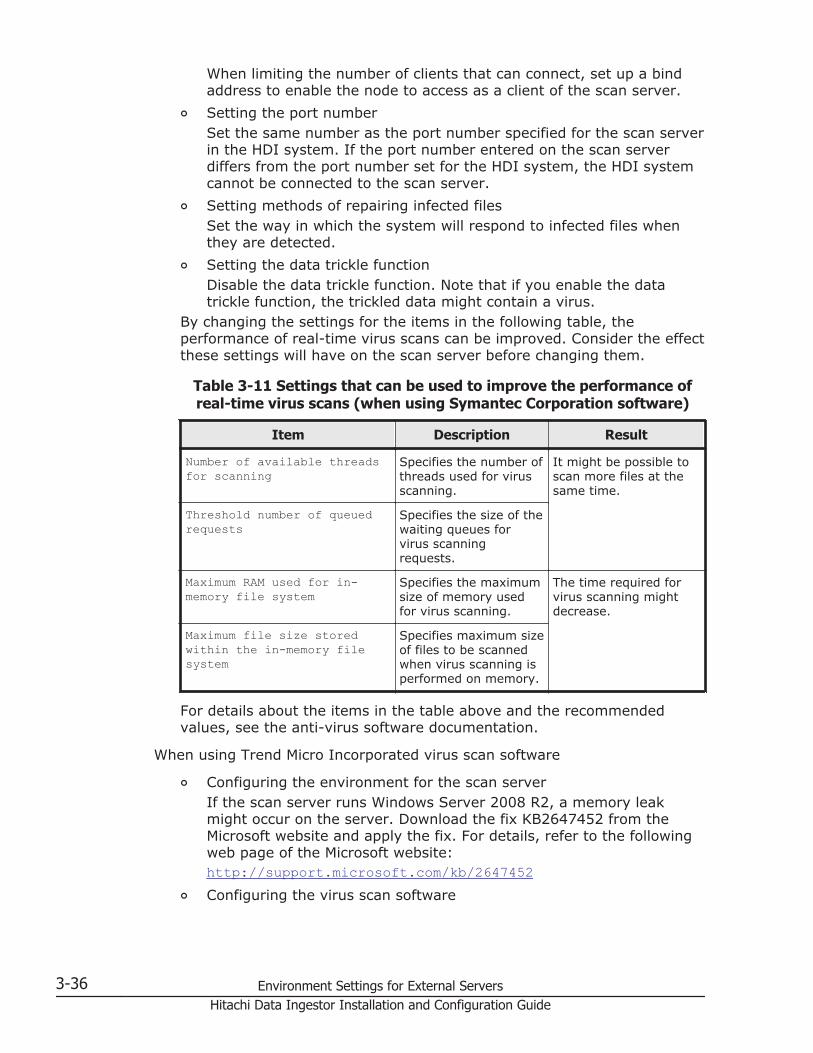
When limiting the number of clients that can connect, set up a bindaddress to enable the node to access as a client of the scan server.
¢ Setting the port numberSet the same number as the port number specified for the scan serverin the HDI system. If the port number entered on the scan serverdiffers from the port number set for the HDI system, the HDI systemcannot be connected to the scan server.
¢ Setting methods of repairing infected filesSet the way in which the system will respond to infected files whenthey are detected.
¢ Setting the data trickle functionDisable the data trickle function. Note that if you enable the datatrickle function, the trickled data might contain a virus.
By changing the settings for the items in the following table, theperformance of real-time virus scans can be improved. Consider the effectthese settings will have on the scan server before changing them.
Table 3-11 Settings that can be used to improve the performance ofreal-time virus scans (when using Symantec Corporation software)
Item Description Result
Number of available threadsfor scanning
Specifies the number ofthreads used for virusscanning.
It might be possible toscan more files at thesame time.
Threshold number of queuedrequests
Specifies the size of thewaiting queues forvirus scanningrequests.
Maximum RAM used for in-memory file system
Specifies the maximumsize of memory usedfor virus scanning.
The time required forvirus scanning mightdecrease.
Maximum file size storedwithin the in-memory filesystem
Specifies maximum sizeof files to be scannedwhen virus scanning isperformed on memory.
For details about the items in the table above and the recommendedvalues, see the anti-virus software documentation.
When using Trend Micro Incorporated virus scan software
¢ Configuring the environment for the scan serverIf the scan server runs Windows Server 2008 R2, a memory leakmight occur on the server. Download the fix KB2647452 from theMicrosoft website and apply the fix. For details, refer to the followingweb page of the Microsoft website:http://support.microsoft.com/kb/2647452
¢ Configuring the virus scan software
3-36 Environment Settings for External ServersHitachi Data Ingestor Installation and Configuration Guide

The virus scan software lets you configure real-time virus scanning orspecify files that should not be scanned.Configure the settings for real-time virus scanning as follows:- The Enable Real-time Scan check box is selected.
- The Incoming & outgoing radio button is selected.
- The Scan mapped network drive check box is selected.
To limit the files to be scanned, use the scan software to specify thefiles that you do not want to be scanned.
¢ Installing and setting up Hitachi Server Protect AgentThe Hitachi Server Protect Agent is required for linking HDI systemsand scan software together to perform real-time scanning. Insert theinstallation media into the scan server, and then execute theHspaInstaller.msi file stored in the HSPA folder to begin installationof Hitachi Server Protect Agent. After the installation finishes, startHitachi Server Protect Agent Manager, and then set the followinginformation. After setting the information, be sure to click OK tocomplete the setting.
Table 3-12 Information required for Hitachi Server Protect Agentsetup
Information category Item
Information for the nodes to be connectedto a scan server (set this information inthe Basic tab)#1
(Up to 32 nodes)
Host name#2:
IP address#3:
CIFS administrator's username#4#5:
CIFS administrator's password:
Settings used for linking to Anti-VirusEnabler (set this information in theAdvanced tab) (optional)
Port number:
Timeout value (0 to 900 seconds):
Queue size (1 to 500):
The number of queues (1 to 4):
Log file size (1 to 10 MB):
The number of log files (1 to 10):
Trace log file size (1 to 10 MB):
The number of trace logs (1 to 10):
#1:If the node information is changed, also change the Hitachi ServerProtect Agent Manager settings.#2:The host name is case sensitive, so make sure that the case isconsistent with that in the host name of the node to be registered.#3:
Environment Settings for External Servers 3-37Hitachi Data Ingestor Installation and Configuration Guide

Use the specified IP address to access the HDI system. If multiplenetwork interfaces are connected to the scan server, use the samenetwork interface for both accepting real-time virus scan requests andaccessing the HDI system.#4:If Active Directory authentication is used to authenticate CIFS users,add the NetBIOS name of the Active Directory domain to the username, as shown below:NetBIOS-name-of-Active-Directory-domain\user-name
You do not need to add the scan server to the Active Directorydomain.#5:The specified CIFS administrator's user information is used foraccessing CIFS shares and performing real-time scanning.
¢ Using DHCP with HDIIf the IP address of an HDI network interface that is connected to thescan server is changed by DHCP, in Hitachi Server Protect Agent, youmust specify FQDN as the IP address for nodes used to connect to thescan server. In this case, node names are resolved every time youperform real-time scanning, which lowers response performance. Werecommend that you connect scan servers to HDI network interfacesthat do not use DHCP.If the node IP address used to connect to the scan server is changedby DHCP, it might take a long time for the new IP address to takeeffect because the old IP address is cached on the scan server. Werecommend that you assign static IP addresses to the nodes and thescan server ports when you configure the DHCP server, and thenspecify the IP addresses from Hitachi Server Protect Agent.
When using McAfee virus scan softwareInstall the add-ons for linking to the storage system. Then, change thesettings according to the following:
¢ Setting a bind addressSet the IP address specified for the scan server in the HDI system inorder to connect to the HDI system.
¢ Setting a port numberSet the same port number as the port number specified for the scanserver in the HDI system.
¢ Scan item optionsEnable the internal scan of compressed files.
¢ What to do when a threat is detectedSet Remove as the first thing to do.
¢ What to do when a suspicious program is detectedSet Remove as the first thing to do.
3-38 Environment Settings for External ServersHitachi Data Ingestor Installation and Configuration Guide

By changing the settings for the items in the following table, theperformance of real-time virus scans can be improved. Consider the effectthese settings will have on the scan server before changing them.
Table 3-13 Settings that can be used to improve the performance ofreal-time virus scans (when using McAfee anti-virus software)
Item Description Result
Maximum scantime(seconds)
Specifies a timeout value forvirus scans.
Files are less likely to causea timeout while they arebeing scanned.
Number of scanthreads
Specifies the number ofthreads to be used for virusscans.
It might be possible to scanmore files at the same time.
For details about the items in the table above and the recommendedvalues, see the anti-virus software documentation.
Environment settings for a tape device connected to a nodevia a SAN
This subsection describes how to set up a tape device that is connected to anode via a SAN. A tape device connected to a node via a SAN can be used incluster configurations.
Registering tape drive informationA tape device that is only physically connected to a node via a SAN is notusable. When a new tape device is installed, after the maintenance personneland SAN administrator are done installing the tape device (for example,connecting it, and setting up the FC switch zones), the system administratorneeds to register the tape drive information with the NDMP server.
If multiple nodes share tape drives, register the information for the sharedtape drives on each NDMP server. If the nodes use separate tape drives,register the information for each tape drive on each NDMP server.
For details on how to register tape drive information on the NDMP server, seethe CLI Administrator's Guide.
To check whether tape drive information is already registered, execute thetapelist command without any options specified.
Enabling the registration information of tape drivesIf the registration information of tape drives is disabled after you haveregistered the tape drives, you cannot use the tape drives to execute backupand restore operations until you have re-enabled the registration information.
Environment Settings for External Servers 3-39Hitachi Data Ingestor Installation and Configuration Guide

Tape drive information can be disabled if the system administrator manuallydisables it by specifying the -i option and running the tapedel command.
When the registration information of tape drives is disabled, re-enable theregistration information before starting a backup or restore operation thatuses the tape drives.
Unregistering tape drive informationWhen a tape device connected to a node via a SAN is no longer needed,remove the tape drive information registered in the backup managementsoftware, and then unregister the tape drive information from the NDMPserver. For details on how to unregister tape drive information, see the CLIAdministrator's Guide.
Notes on setting up a tape device connected to a node via a SANNote the following points when setting up a tape device that is connected to anode via a SAN:
• When you are using a tape device whose block size can be changed bythe backup management software, if you change the block size afterperforming a backup operation, you might not be able to restore backupdata stored on the tape device.
• Make sure that you use a tape drive registered on a node on which abackup or restore operation is to be performed. If you use a tape driveregistered on another node, the data to be backed up or restored mighttravel over the LAN.
• When the system is operating in degenerate mode, an error might occurduring a backup or restore operation, or you might have to change thesettings to perform a backup or restore operation. For notes on operatingthe system in degenerate mode, see the Troubleshooting Guide.
Replacing of tape devicesThis subsection explains how you can replace a tape device in cooperationwith maintenance personnel or the SAN administrator. For details on thecommands used in the procedure, see the CLI Administrator's Guide.
To replace a tape device:
1. Use the backup management software to unregister the tape device youwant to replace.
2. Execute the tapedel command to delete the information about the tapedrives registered on the NDMP servers on all nodes.
3. Working with the SAN administrator, remove the FC cable connected tothe tape device that you want to stop using.
4. Working with maintenance personnel or the SAN administrator, replacethe tape device.
3-40 Environment Settings for External ServersHitachi Data Ingestor Installation and Configuration Guide

5. Working with the SAN administrator, connect the FC cable to the newtape device.
6. Execute the tapeadd command to register the tape drive on the NDMPservers.
7. Use the backup management software to register the new tape device.
Stopping use of a tape deviceThis subsection explains how you can stop using a tape device in cooperationwith maintenance personnel or the SAN administrator. For details on thecommands used in the procedure, see the CLI Administrator's Guide.
To stop using a tape device:
1. Use the backup management software to unregister the tape device thatyou want to stop using.
2. Execute the tapedel command to delete the information about the tapedrives registered on the NDMP servers on all nodes.
3. Working with the SAN administrator, remove the FC cable connected tothe tape device that you want to stop using.
4. Remove the tape device.
SMTP server environment settingsTo receive email notifications containing error information when errors occurin an HDI system or when users perform an invalid operation, an SMTP serveris required for sending emails to preset addresses. This section describes theSMTP server environment settings.
If an SMTP server is already set up in a LAN containing HDI nodes, you canuse that SMTP server. If no such SMTP server exists, you need to install anSMTP server in the LAN or connect the LAN to a network in which an SMTPserver exists.
Client machines must support Unicode (UTF-8) to receive emails.
DHCP server environment settingsA DHCP server is required in a single-node configuration when DHCP is usedto set the interface of a node. This section describes the DHCP serverenvironment settings.
To automatically register node host names to the DNS server, enable theDDNS functionality on the DHCP server and DNS server. For details about theenvironment settings on the DNS server, see DNS server environmentsettings on page 3-42.
The DHCP server manages the following settings that HDI uses:
• IP addresses and subnet masks
Environment Settings for External Servers 3-41Hitachi Data Ingestor Installation and Configuration Guide

• Default gateway
• MTU (Specify 1,500 for this value.)
• DNS server
• The domain where the node belongs and the domain you want to be thesearch target for name resolution
• Routing information (static route)
We recommend that you manage the routing information from the DHCPserver instead of setting the routing information in HDI.
When you manage the DNS server information from the DHCP server, thesettings from the DHCP server will be used after you restart the OS on nodeseven if you set the DNS server in HDI.
DNS server environment settingsWhen using DHCP in a single-node configuration, you must configure theenvironment settings of the DNS server to automatically register node hostnames to the DNS server. Configure the settings as follows:
• Enable the DDNS functionality. Also change the security settings to permitdynamic updating of DNS records from the DHCP server.
• Enable scavenging of stale resource records so that unused records canbe deleted.
3-42 Environment Settings for External ServersHitachi Data Ingestor Installation and Configuration Guide

4About HDI
This chapter describes various points that system administrators mustunderstand and take into consideration before using an HDI system.
For details about backup operations in an HDI system, see Chapter 5, BackupOperations in an HDI System on page 5-1.
If the HDI system operation links with HCP, see Chapter 6, Linking HDI andHCP on page 6-1 before starting this chapter.
Note:
Make sure you refer to Notes on managing an HDI system (required reading)on page 4-3.
□ Notes on managing an HDI system (required reading)
□ About cluster configurations
□ About client user information
□ About HDI with user mapping
□ About file systems
□ About setting quotas
□ About file sharing
□ About real-time virus scanning
□ About system settings
□ About errors
About HDI 4-1Hitachi Data Ingestor Installation and Configuration Guide

□ About monitoring systems with SNMP
□ About importing data from other file servers
□ About clients using file systems
4-2 About HDIHitachi Data Ingestor Installation and Configuration Guide
Notes on managing an HDI system (required reading)The system administrator needs to keep the following in mind whenmanaging an HDI system:
• If you change the configuration of an HDI system, you need to downloadthe system settings file saved on the system LUs, and then save it onstorage media outside the system.
• Do not run commands while operations are being performed on the HDIsystem by way of the GUI.
• Multiple system administrators cannot simultaneously specify or updatesystem settings within a cluster. For this reason, if multiple systemadministrators are registered, ensure that only one system administratorhas the ability to register or modify information.
• If you specify a host name for the management IP address of the node orthe IP address of the management port of the storage system controller,in advance, you need to specify settings for the management server sothat names can be resolved.
• When changing any DNS server settings after starting an HDI system,you must restart the OS on both nodes in the cluster after the changesare made.
• If NFS shares are being used, do not make any changes to anenvironment in which host names can be resolved after the HDI systemhas been started. An environment in which host names can be resolved isan environment in which the IP address and host name of an NFS clientare registered in the /etc/hosts file of the OS on the node, NIS server,or DNS server so that the host name can be converted into an IP address.If any changes are made to an environment in which host names can beresolved after an NFS share is created, attempting to access a file systemfrom an NFS client might cause an error to occur.
• If you stop the NFS service, contact the administrators of the NFS clienthosts and ask them not to access the NFS share until the NFS servicestarts.
• If you register a client host name on a DNS server set up on the DNS,NIS, LDAP Setup page of the Network & System Configurationdialog box, and then use an HDI system, check the NFS client host'sname resolution beforehand. Confirm that the name resolution (bothforward lookup and reverse lookup) responds normally within a shorttime. For details on how to check the result of DNS name resolution, seethe Troubleshooting Guide. If the DNS server does not respond normallyand within a short amount of time, check the DNS server settings.If you start an HDI system without registering an NFS client host on theDNS server set up on the DNS, NIS, LDAP Setup page of the Network& System Configuration dialog box, confirm beforehand that the NFSclient host's name resolution sends a error response within a short time.If the DNS server does not respond with an error within a short amount oftime, ensure that the processing of queries to the DNS server does nottake a long time. You can do this by configuring the system so that theDNS server that is specified on the DNS, NIS, LDAP Setup page does
About HDI 4-3Hitachi Data Ingestor Installation and Configuration Guide

not request another DNS server's name for name resolution. Oneconfiguration option is defining a reverse lookup zone on the DNS server.If the DNS server does not send an error response in a timely manner,change the settings so that name resolution is not performed on any DNSservers except the one that was set from the DNS, NIS, LDAP Setuppage. Do this in order to define a reverse lookup zone on the DNS server.
• Be sure to check the following if you are using the CIFS service andperforming DNS name resolution for a domain controller or LDAP serverfor user mapping:
¢ Whether the DNS server can perform name resolution for the domaincontroller or LDAP server (forward lookup)
¢ Whether the DNS server quickly responds when performing nameresolution for the domain controller or LDAP server (both forwardlookup and reverse lookup)
For details on how to check the result of DNS name resolution, see theTroubleshooting Guide. If the DNS server does not send a normalresponse, check and if necessary, revise the settings for the DNS serversuch as the record settings, zone settings, and recursion settings.
• In an environment where host names can be resolved, note the followingto register or delete a host name:
¢ When creating an NFS share for a given host, make sure that a hostname for the host is registered.
¢ When specifying a netgroup for creating an NFS share, always use thesame type of name resolution (conversion from an IP address to ahost name, and vice versa) for the host name of the NFS client fromwhich a target file system is mounted.
¢ When deleting a host name used in an NFS share for a given host,delete the corresponding NFS share, and then delete the host name.
¢ When using an NFS share for file locking, if an NFS client that has afile lock terminates abnormally and cannot be restarted, you mustdelete the file lock information. For details on how to delete file lockinformation, see the CLI Administrator's Guide.
• The password specified by a system administrator when user informationis registered should be used only temporarily. For any users added fromthe Add User page or the Batch Operation page of the Local Usersdialog box, the system administrator must inform the users that theyneed to change their own passwords.
• If you are using Active Directory, users that have Active Directoryauthentication can access the CIFS shares. Users that are locallyauthorized in the HDI system cannot access the CIFS shares.
• If the system goes down, or an error causes the OSs of both nodes withina cluster to stop, and you restart only one node to resume operation,check whether the KAQG72011-E message was output on the List of RASInformation page (for List of messages) of the Check for Errorsdialog box. If the relevant settings are enabled, the information can bealso sent by using an SNMP trap or email. If the KAQG72011-E message
4-4 About HDIHitachi Data Ingestor Installation and Configuration Guide

was output, wait until the OS on the node (for which the message wasoutput) is stopped, and then start the OS on the other node.
• If a failover occurs, services associated with the resource group, for whichthe failover occurred, cannot be started, stopped, or restarted.
• On the Browse Cluster Status page (for Resource group status) ofthe Cluster Management dialog box, if Online / No error is displayedfor Resource group status, the file systems, NFS services, CIFSservices, and virtual IP addresses can be managed from File ServicesManager. Because the resource groups start up only after the cluster isrunning normally, the statuses of the resource groups are displayed asOnline Pending immediately after the status of the cluster is displayedas ACTIVE for Cluster status on the Browse Cluster Status page (forCluster / Node status). In this situation, file systems, NFS services,CIFS services, or virtual IP addresses cannot be used. Before using a filesystem, an NFS service, a CIFS service, or a virtual IP address, confirmthat the resource group status is Online / No error.
• When a resource group is started, the HDI system will block anyresources in which an error is detected. The HDI system will use otherresources to configure the resource group. When a resource group ispartially blocked, some services in the node will be stopped but theremaining services will still be provided. If this happens, the BrowseCluster Status page (for Resource group status) of the ClusterManagement dialog box displays Online / No error, and you will notbe able to check the error information about the resource group.A partial blockage of a resource group might occur at the following times:
¢ When operation of the HDI system starts
¢ When a failover or failback occurs
¢ When a resource group is restartedIf any of the operations previously listed are performed, or Online / Noerror is displayed on the Browse Cluster Status page (for Resourcegroup status) (even though you cannot access the file system), fromthe List of RAS Information page (for List of messages) of theCheck for Errors dialog box, you will need to check the systemmessages to see whether a partial blockage occurred in one of theresource groups.The system administrator must check whether the KAQG72006-Emessage is output as a system message.Note that, depending on the resource type, resources that use a blockedresource might also become blocked. For example, if a logical volume isblocked, the file system created in that logical volume is also blocked. Ifthis happens, the KAQG72006-E message will be output for each blockedresource.
• If the management process for the file system is interrupted due to, forexample, the operating system not running, you might be unable torepeat the same operation. In this case, refresh the processing node orexecute the fslist command to check the status of the file systembefore following the instructions in the message.
About HDI 4-5Hitachi Data Ingestor Installation and Configuration Guide
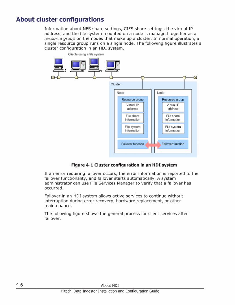
About cluster configurationsInformation about NFS share settings, CIFS share settings, the virtual IPaddress, and the file system mounted on a node is managed together as aresource group on the nodes that make up a cluster. In normal operation, asingle resource group runs on a single node. The following figure illustrates acluster configuration in an HDI system.
Figure 4-1 Cluster configuration in an HDI system
If an error requiring failover occurs, the error information is reported to thefailover functionality, and failover starts automatically. A systemadministrator can use File Services Manager to verify that a failover hasoccurred.
Failover in an HDI system allows active services to continue withoutinterruption during error recovery, hardware replacement, or othermaintenance.
The following figure shows the general process for client services afterfailover.
4-6 About HDIHitachi Data Ingestor Installation and Configuration Guide

Figure 4-2 Example of the general process for client services (during afailover)
An IP address that clients use to connect to a resource group service is calleda virtual IP address. When the node on which a resource group is runningchanges to the other node, the virtual IP address is passed to the other node.Because clients use the virtual IP address to connect to the service, clientscan access files even after a failover occurs. Virtual IP addresses areassociated with interfaces on a node. When a resource group is moved toanother node in the same cluster, the virtual IP address is associated with thesame interface on the destination node. For example, the virtual IP addresspreviously associated with the fixed IP address of eth1 in the original nodewill be associated with the fixed IP address of the interface eth1 in thedestination node.
In an HDI system, services are provided by mounting a different file systemfor each resource group. By planning the network configuration, and themounting of file systems, a system administrator can distribute file accessacross both nodes and balance the loads between the nodes.
About HDI 4-7Hitachi Data Ingestor Installation and Configuration Guide

Normal operation restarts when a failed-over resource group is failed back tothe original node after an error recovery operation. A system administratorfails back a resource group by changing the node on which the resourcegroup is running. As a system administrator, if you need to carry out failback,you should follow the instructions of the maintenance personnel.
About client user informationIn an HDI system, clients are identified by user IDs and group IDs. Thesystem administrator can use the following methods to manage client userinformation. The maximum number of user information items that can bemanaged by each method is the number of user information items per cluster(or node in a single-node configuration).
Using an HDI system to manage user information:Using this method, a maximum of 2,000 items of user informationregistered in an HDI system can be managed.
Using an NIS server or an LDAP server (or both) to manage user information:Using this method, a maximum of 50,000 items of user informationregistered in an HDI system, an NIS server, or an LDAP server can bemanaged. Server information must be set in advance in an HDI system toenable management by using an NIS server or LDAP server. Note that theNIS server can be used for managing user information only when IPv4 isused.
Using Active Directory or the NT domain to manage user information:To assign user IDs and group IDs to user information used for userauthentication, user mapping is required, or else user information (userIDs and group IDs) must be managed by an HDI system, an NIS server,or an LDAP server.The maximum number of user information items that can be managed bythe domain depends on the OS of the domain controller. In all theaccessible domains (including domains in trust relationships), themaximum number of users for which user mapping is used is shownbelow:
When using Active Directory schema2,147,482,948 (the total number of user IDs for all the domains)
When using RIDs2,147,412,648 (the total number of user IDs and group IDs for all thedomains)
Note that the NT domain can be used for managing user information onlywhen IPv4 is used.
4-8 About HDIHitachi Data Ingestor Installation and Configuration Guide

About HDI with user mappingThe types of IDs that an HDI system or Windows uses to identify users differ.HDI systems use user IDs and group IDs, while Windows uses unique IDscalled security identifiers (SIDs).
For an HDI system, if CIFS clients accessing file systems will be authenticatedby way of Active Directory authentication or NT domain authentication, youcan use user mapping to assign user IDs or group IDs.
User mapping also allows you to manage users who belong to 32 or moregroups.
This section explains how user mapping is managed in an HDI system anddescribes the settings necessary to use user mapping.
Domains that allow access to an HDI systemWhen user mapping is used, users who belong to a domain that is in a trustrelationship with the domain that the nodes belong to can also access theCIFS shares in an HDI system.
To access an HDI system, users must belong to a domain that is in amutually trusting relationship with the domain that the nodes belong to.
In order to establish a trusting relationship between forests, their rootdomains must have a mutually trusting relationship.
Users cannot access CIFS shares if the users belong to a domain for whichthe forest is in a unilaterally trusting relationship with the forest containingthe domain that the nodes belong to.
The figures below show the scopes of the domains from which users can useHDI CIFS shares.
About HDI 4-9Hitachi Data Ingestor Installation and Configuration Guide

Figure 4-3 Node belonging to the root domain
Figure 4-4 Node belonging to a child domain, when there is a mutuallytrusting relationship between the forests
4-10 About HDIHitachi Data Ingestor Installation and Configuration Guide

Figure 4-5 Node belonging to a child domain, when there is no mutuallytrusting relationship between the forests
Figure 4-6 Only a unilaterally trusting relationship between the forests
To access an HDI system when the nodes belong to an Active Directorydomain, users who belong to a domain that is not in a parent-childrelationship with the domain that the nodes belong to must explicitly set up atrust relationship with that domain.
User mapping methodsThe following describes the user mapping methods provided by HDI systems:
• User mapping using RIDs (automatic assignment)
• User mapping using LDAP (automatic or manual assignment)
About HDI 4-11Hitachi Data Ingestor Installation and Configuration Guide

• User mapping using Active Directory schema (manual assignment)
We recommend that you use RIDs, because they are less susceptible tocommunication errors in the HDI system.
User mapping using RIDs
User mapping using RIDs authenticates CIFS clients via Active Directoryauthentication or NT domain authentication.
When a CIFS client accesses an HDI file system, the system converts the setof relative identifiers (RIDs) contained in the SID and automatically assigns auser ID or group ID to the client.
The system administrator uses File Services Manager to specify a range ofuser IDs and group IDs for each domain, allowing users and groups to bemanaged by their domain. Mapping information does not need to be stored ina database or managed on an external server when user mapping using RIDsis used. The assignment of user IDs and group IDs takes less time and thesystem is less vulnerable to errors on the network or external server.
You can manage a maximum of 256 domains when user mapping using RIDsis used. If you have 257 or more domains, choose user mapping using LDAPor an Active Directory schema.
User mapping using LDAP
User mapping using LDAP authenticates the CIFS client via Active Directoryauthentication or NT domain authentication.
You can choose to automatically or manually assign user IDs and group IDs.
If you choose automatic assignment, user IDs or group IDs within the rangespecified in File Services Manager will be assigned automatically when theCIFS client accesses an HDI file system. Information about the assigned userID or group ID is registered in the database of the LDAP server set up as anexternal server. When the CIFS client next accesses the file system, the userID or group ID that was already assigned is used.
If you choose to manually assign user IDs and group IDs, they will beassigned according to the user information that was registered beforehand inthe LDAP server database.
User mapping using the Active Directory schema
User mapping using the Active Directory schema authenticates the CIFS clientvia Active Directory authentication.
User mapping using the Active Directory schema allows you to combine thedifferent IDs a user has from NFS and CIFS clients and treat them as thesame user by using the Active Directory user attributes. Furthermore, you donot need to prepare an external server for user mapping, because user IDsand group IDs will be assigned according to the user information that wasregistered in the domain controller beforehand.
4-12 About HDIHitachi Data Ingestor Installation and Configuration Guide

Changing the user mapping methodEach user mapping method has its own unique way of assigning user IDs andgroup IDs. The IDs assigned to CIFS clients differ depending on the usermapping method that is used.
If you change the user mapping method after starting the operation of theHDI system, the user IDs and group IDs assigned to CIFS clients will bechanged. This might allow unauthorized users to access files and folders thatwere created before you changed the user mapping method. In order tochange the user IDs and group IDs associated with files and folders to theIDs used by the new user mapping method, the CIFS administrator has tomigrate the file system by using the Windows backup function. For other OSs,see the documentation provided with the OSs.
The following procedure is for migrating file systems when the usermapping method is changed from the LDAP method (thatautomatically assigns user IDs and group IDs) to the RID method:
1. Contact the end users.Ask the end users to not access the CIFS shares while this procedure isbeing performed.
2. Limit access from the CIFS client hosts.From Host access restrictions on the CIFS Service Managementpage (Setting Type: Security) of the Access Protocol Configurationdialog box, limit access to only the CIFS client host on which theadministrator will migrate the file systems.
3. Set up a CIFS administrator.From CIFS administrator name(s) on the CIFS Service Managementpage (Setting Type: Administration) of the Access ProtocolConfiguration dialog box, specify the CIFS administrator that you wantto have migrate the file systems.
4. Restart the CIFS service.From the List of Services page of the Access Protocol Configurationdialog box, restart the CIFS service.
5. Ask the CIFS administrator to back up the data in the source CIFS shares.We recommend that the CIFS administrator use the Windows backupfunction. If the data is backed up using another method, the ACLs and fileattributes might not be restored correctly. Note that data created by NFSclients cannot be migrated by using the Windows backup function.
6. Change the user mapping method.From the CIFS Service Management page (Setting Type: Usermapping) of the Access Protocol Configuration dialog box, specify therequired information in User mapping setup.
7. Restart the CIFS service.From the List of Services page of the Access Protocol Configurationdialog box, restart the CIFS service.
8. Create and mount a file system.
About HDI 4-13Hitachi Data Ingestor Installation and Configuration Guide
From the Create File System dialog box, create and mount a filesystem. Create the file system so that the capacity is the same size as thesource file system capacity or larger. All other settings should be identicalto those on the source file system.
9. Specify quotas for the target file system.If a default, user, or group quota was specified on the source file system,use the same quota value for the target file system.To specify a default, user, or group quota, use the quotaset command. Ifyou do not want to set a limit on the block and inode usage for aparticular user or group, specify 0 for the soft and hard limits.
10. Create CIFS shares on the target file system.From the Add Share dialog box, create CIFS shares on the target filesystem, and then specify names for the CIFS shares that differ from thesource CIFS share names. For the target CIFS shares, use the samesettings as those for the source CIFS shares.
11. Specify a subtree quota.If a subtree quota has been specified for the source CIFS-shareddirectory, specify the same value for the target CIFS-shared directory.Use the stquotaset command to specify a subtree quota. If you do notwant to set a limit on the block and inode usage for a particular user orgroup, specify 0 for the soft and hard limits.
12. Ask the CIFS administrator to restore the data to the target CIFS shares.Ask the CIFS administrator to restore the data backed up in step 5 to thetarget CIFS shares created in step 10.
13. Make sure that the data has been correctly migrated.Compare the data in the source CIFS shares with the data in the targetCIFS shares, and make sure that the data was successfully migrated.When comparing the source CIFS shares with the target CIFS shares, werecommend that you check the following:
¢ The structures of the folders are the same.
¢ The contents of the files are the same.
¢ The information about the owners, ACLs, and file attributes are thesame.
14. Release the source CIFS shares, if necessary.If you want to change the target CIFS share names to the source CIFSshare names, click the Release Share button in the following window oron one of the following tabs to release the source CIFS shares:Cluster configuration:
¢ Shares subwindow
¢ Shares tab in the physical-node subwindow
¢ Shares tab in the file-system subwindowSingle-node configuration:
¢ Shares window
¢ Shares tab in the file-system-name window
4-14 About HDIHitachi Data Ingestor Installation and Configuration Guide
15. Delete the source file system, if necessary.You can delete the source file system, if it is no longer needed. Click theDelete File System button in the following window or tab to delete thesource file system:Cluster configuration:
¢ File Systems subwindow
¢ File Systems tab in the physical-node subwindowSingle-node configuration: File Systems tab in the File Systems window
16. Change the target CIFS share names, if necessary.If the source CIFS shares were released in step 14, from the Edit Sharedialog box, you can rename the target CIFS share names to the deletedsource CIFS share names.
17. Delete the CIFS administrator that was created, if necessary.If the CIFS administrator created in step 3 is not necessary, delete theCIFS administrator from CIFS administrator name(s) on the CIFSService Management page (Setting Type: Administration) of theAccess Protocol Configuration dialog box.
18. Remove the access limit to the CIFS client hosts.From Host access restrictions on the CIFS Service Managementpage (Setting Type: Security) of the Access Protocol Configurationdialog box, remove the access limit to the CIFS client hosts that was setup in step 2.
19. Restart the CIFS service.From the List of Services page of the Access Protocol Configurationdialog box, restart the CIFS service.
Note:After changing the user mapping method, delete the source CIFS shares.Because some of the user mapping information will still exist in the cachememory, an error could occur if you try to view a Properties window forany of the files and folders that were on the source file system. Use theCIFS Service Maintenance page of the Access ProtocolConfiguration dialog box to delete the user mapping information cachedin the CIFS service environment.
Examples of assigning user IDs and group IDs with user mappingusing RIDs
An RID is assigned to each user, group, and computer account, regardless ofthe type of object it is. As a result, there will be some IDs that are assignedby using RIDs but not actually used for file access. When thinking about whatrange to use for the user IDs and group IDs that will be assigned, rememberthat the range should also include IDs that will not be used for the purposesof file access.
The following figure shows how user IDs and group IDs are assigned by usermapping using RIDs.
About HDI 4-15Hitachi Data Ingestor Installation and Configuration Guide

Figure 4-7 Example of assigning user IDs and group IDs by using RIDs
After a range of user IDs and group IDs has been set, you cannot change theminimum value of the range set for the user IDs and group IDs that areavailable for user mapping. When thinking about what range you want to setfor the user IDs and group IDs, be sure to overestimate the necessary range,taking into account all future operational plans and the range of user IDs andgroup IDs that will be needed for other domains or external servers. Whenchanging the range, if the amount of space necessary for allocating the IDsyou want to add is insufficient, you will need to recreate the file system.
When setting the range of IDs available for user mapping, you must also takeinto consideration future increases in the number of SIDs. At the very least,the range of IDs you decide upon must contain the range of RIDs that arealready in use. To ensure that you set an appropriate range of IDs availablefor user mapping, determine what that range is from the largest RID in use.
A system administrator can use various applications for such a task, such asone provided by Microsoft, to acquire the SID of the object that was lastadded to the domain controller. This SID will indicate to the systemadministrator what the largest RID currently in use is. If there are multipledomain controllers in the same domain, the system administrator can checkthe largest RID by acquiring the SID of the last added object for each domain
4-16 About HDIHitachi Data Ingestor Installation and Configuration Guide
controller. For details on how to acquire an SID, see the documentation forthe application you are using to acquire the SIDs.
For example, suppose that user mapping using RIDs will be used under thefollowing conditions:
• There are two domains (Domain1 and Domain2).
• The domains have a direct trust relationship with each other.
• The largest RID that is currently in use is 8000.
• 1,000 users will be added to each domain annually. (However, from thesecond year on, 1,000 users will be deleted annually.)
• 1,000 computer accounts will be added to each domain annually.(However, from the second year on, 1,000 computer accounts will bedeleted annually.)
• Groups and other objects will not be added or deleted.
• The domains will be in use for 100 years.
• A 50% margin will be added to the range of user IDs and group IDs to beused in order to account for the uncertainty of the rate in which objectswill increase.
Number of SIDs per domain that are being used when you estimate a range:Number-of-SIDs = (largest-RID-currently-in-use)=8,000
Annual increase in SIDs per domain after the first year:Number-of-SIDs = (number-of-users-added) + (number-of-computer-accounts-added)1,000 + 1,000 = 2,000
The following figure shows an example of how to estimate the total numberof user IDs and group IDs required under the above conditions.
About HDI 4-17Hitachi Data Ingestor Installation and Configuration Guide

Figure 4-8 Example of how to estimate the total number of user IDs andgroup IDs required
A total of 2,000 objects will be added annually. Therefore, the number ofSIDs will increase by 2,000 each year. From the second year, a total of 2,000objects will be deleted annually. However, IDs used for deleted objectscannot be reused.
Number of IDs required for each domain (Domain1 and Domain2):Number-of-IDs-required-per-domain = (number-of-SIDs-currently-in-use + (increase-in-the-number-of-SIDs-per-year x number-of-years-operations-will-continue)) x (100 (%) + margin (%))(8,000 + (2,000 x 100)) x 1.5 = 312,000
Number of IDs required for all domains (total number of IDs required for alldomains):
Number-of-IDs-required-for-entire-domains = number-of-IDs-required-for-domain-1 + number-of-IDs-required-for-domain-2 + ...312,000 + 312,000 = 624,000
For the above example, specify a range of user IDs and group IDs from70000 to 2147483147. The following examples show what range of user IDsand group IDs to use for the above estimate when the minimum value of userIDs and group IDs is 1000000.
4-18 About HDIHitachi Data Ingestor Installation and Configuration Guide
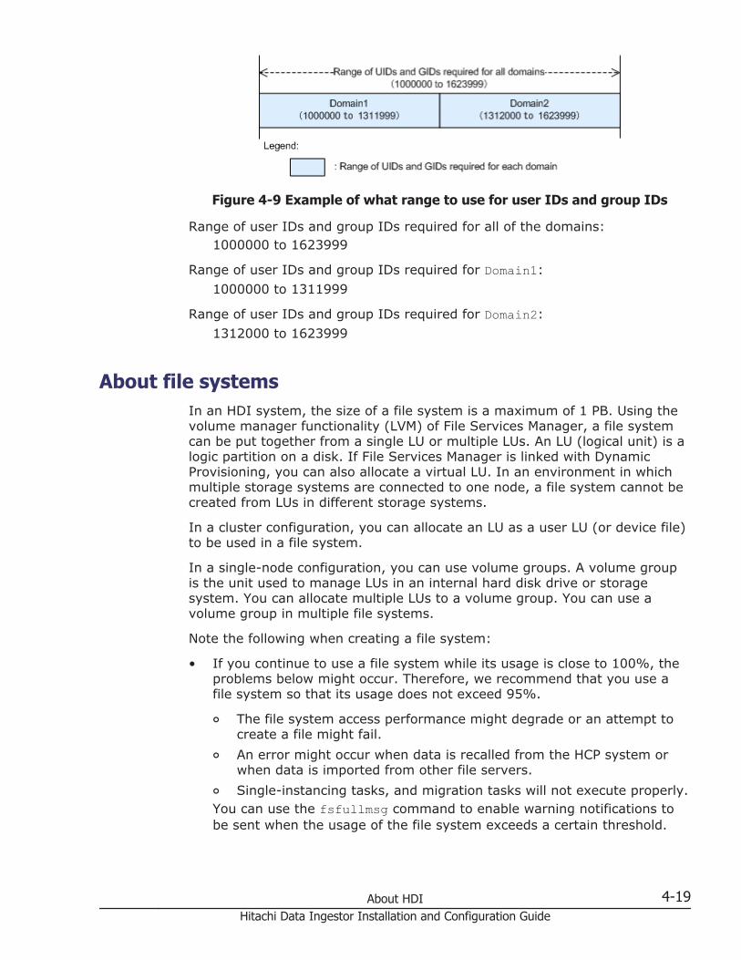
Figure 4-9 Example of what range to use for user IDs and group IDs
Range of user IDs and group IDs required for all of the domains:1000000 to 1623999
Range of user IDs and group IDs required for Domain1:
1000000 to 1311999
Range of user IDs and group IDs required for Domain2:
1312000 to 1623999
About file systemsIn an HDI system, the size of a file system is a maximum of 1 PB. Using thevolume manager functionality (LVM) of File Services Manager, a file systemcan be put together from a single LU or multiple LUs. An LU (logical unit) is alogic partition on a disk. If File Services Manager is linked with DynamicProvisioning, you can also allocate a virtual LU. In an environment in whichmultiple storage systems are connected to one node, a file system cannot becreated from LUs in different storage systems.
In a cluster configuration, you can allocate an LU as a user LU (or device file)to be used in a file system.
In a single-node configuration, you can use volume groups. A volume groupis the unit used to manage LUs in an internal hard disk drive or storagesystem. You can allocate multiple LUs to a volume group. You can use avolume group in multiple file systems.
Note the following when creating a file system:
• If you continue to use a file system while its usage is close to 100%, theproblems below might occur. Therefore, we recommend that you use afile system so that its usage does not exceed 95%.
¢ The file system access performance might degrade or an attempt tocreate a file might fail.
¢ An error might occur when data is recalled from the HCP system orwhen data is imported from other file servers.
¢ Single-instancing tasks, and migration tasks will not execute properly.You can use the fsfullmsg command to enable warning notifications tobe sent when the usage of the file system exceeds a certain threshold.
About HDI 4-19Hitachi Data Ingestor Installation and Configuration Guide
• For the total number of directories and files that can be created in adirectory, we recommend specifying a number that does not exceed10,000.
• A maximum of approximately four billion files can be created in one filesystem.Note that the actual maximum number of files to be created in a filesystem differs depending on conditions such as the lengths of file pathsand the number of files to be created in a directory. If you want to createmore files than the maximum number described above, use an additionalfile system. To prevent the number of files from exceeding the maximum,you can use the fsfullmsg command to monitor the amount of inodesused. In addition, an SNMP trap or email (KAQG90003-W) can be sentwhen the warning threshold is exceeded. In addition, you can use thefslist command to periodically check the number of used inodes (I-node used) and number of remaining inodes (I-node free).
• In the initial settings, the inode information is stored in the first 1-TB areaof the file system. The file expansion attribute is stored in an areadifferent from the inode if the file system was created by an HDI version4.2.3-03 or later.If you use the fsinodectl command so that 64-bit inodes can behandled, the inode information will be stored in all areas of the filesystem, and the inode areas can be secured. However, once you modifythe settings, the settings cannot be changed back to the initial settings.In addition, some applications do not support 64-bit inodes. If suchapplications are used, you must not use the fsinodectl command tohandle 64-bit inodes.
• In an HDI system, one block (whose size is 4 KB) is assigned for each file.
• In a file system set up on an HDI system, you can also save the filecreation time, as well as the last access time (atime), the last changetime (ctime), and the last modification time (mtime), to improvecompatibility with the CIFS client environment. However, you cannot viewthe file creation time from an NFS client.
In addition, the following explains what you need to know in order to managefile systems.
Creating an LU (device file) or volume groupThere are two types of LUs that are used in the HDI system: a user LU usedfor the file system, and a cluster management LU where settings such asthose related to a cluster configuration and file system are stored.
The system administrator creates LUs by using Device Manager or HitachiStorage Navigator Modular 2 when configuring a file system in a storagesystem. By using Device Manager or Hitachi Storage Navigator Modular 2,LUs can be created while considering factors, such as disk drive configuration,parity groups, and I/O performance. For details about creating LUs, see themanual for Device Manager or Hitachi Storage Navigator Modular 2. If youare not the storage system administrator, ask the person who is the storagesystem administrator to create the LUs for you. If the system is a cluster
4-20 About HDIHitachi Data Ingestor Installation and Configuration Guide

configuration, make sure to create the LUs for the cluster management LU inthe storage system as well. The cluster management LU requires 70 GB ofcapacity.
Including the LUs that are automatically created during file system creationor expansion, a maximum of 511 LUs having a hexadecimal LUN in the rangefrom 0000 to 01FF can be created in a cluster configuration. In a single-nodeconfiguration, a maximum of 256 LUs having a hexadecimal LUN in the rangefrom 00 to FF can be created.
Specify the LUN (host LU number) for a storage system as a number from 0to 511. If the specified LUN is 512 or more, the LU with this LUN cannot beused in the HDI system.
In a single-node configuration in which the internal hard disk of the node isused for a file system, the HDI system automatically allocates LUs to theinternal hard disk when the node OS is started. The system administratordoes not need to create LUs.
After the LUs are created, perform the following tasks as necessary.
For a cluster configurationBy default, an LU in a storage system connected to a node via an FC pathis automatically allocated as a user LU (device file). When settings arechanged to prevent user LUs from being automatically allocated, such asduring maintenance, the system administrator must manually allocateuser LUs. For details about manually allocating user LUs that areconnected to a node via an FC path, see the CLI Administrator's Guide.
For a single-node configurationBy default, an LU that is connected to an internal hard disk drive or anode via an FC path is automatically allocated to a newly created volumegroup. When LUs are automatically allocated to volume groups, aseparate volume group is created and used to manage LUs that are of thesame drive type (or pool for virtual LUs) and that are in the same chassis(internal hard disk drive or storage system).When you create LUs after adding an internal hard disk drive or storagesystem, you can use a Web browser to log on to the HDI system andautomatically allocate the LUs to volume groups. For details about how toadd a drive, see the Administrator's Guide.
Notes on allocating LUsNote the following points when you allocate LUs to file systems in a clusterconfiguration or when you allocate LUs to volume groups in a single-nodeconfiguration:
• The I/O characteristics and processing speed differ depending on the LUdrive type. When considering which LUs to use, the system administratormust carefully consider the intended use of the file system and thecharacteristics of the disk drives.
• Do not use LUs that are part of different redundant configurations for afile system or volume group. When the file system or volume group
About HDI 4-21Hitachi Data Ingestor Installation and Configuration Guide

consists of LUs from different redundant configurations, the file system orvolume group depends on the fault tolerance of the LU that has theminimum level of redundancy. For Hitachi AMS2000 series or HUS100series storage systems, use Hitachi Storage Navigator Modular 2 to checkthe LUs before creating the file system or volume group. For VSP G1000,Virtual Storage Platform, Universal Storage Platform V/VM, and HUS VMstorage systems, or if you are not the storage system administrator,contact the person who is the storage system administrator.
• If you change the LU capacity created in a storage system, perform arefresh operation for the processing node in a cluster configuration.Execute the fpstatus command in a single-node configuration.
• To link an HDI system to Dynamic Provisioning to allocate a virtual LU toa file system or volume group, make sure that there is enough space onthe pool to which the virtual LU belongs. If there is not enough space inthe pool, an application on a client using the file system might terminateabnormally or an HDI error might occur. If a file system uses a virtual LUcreated from more than one pool and there is not enough space in atleast one of the pools, an error might occur even if the usage of the filesystem does not reach the limit.
• If you are deleting a large amount of files from the file system, executethe dpreclaim command to release the unused area of a virtual LU usedby the file system. By executing the command after deleting 1 GB ormore data, you can prevent the space on the pool to which the virtual LUbelongs from being insufficient. If the capacity of the file system that usesthe virtual LU is less than 256 MB, the dpreclaim command cannot beused to release the unused area of that virtual LU.Take note of the following before executing the dpreclaim command:
¢ While using Hitachi AMS2000 series or HUS100 series storagesystems, you might not be able to release the unused area of a virtualLU even if you execute the dpreclaim command. In this case, useHitachi Storage Navigator Modular 2 to optimize the DP pool after youexecute the command.
¢ Unused areas in the DP pool are released by the page, so these areascannot be released until all areas in their page stop being used.Therefore, you might not be able to free the space of deleted fileseven if you execute the dpreclaim command.
• To release the space on the virtual LU allocated to the deleted file systemor volume group, delete the virtual LU.
• Enable the mapping guard for the LUs of the storage systems that areused in the HDI system. For the LUs that are used in the HDI system, ifyou change the mappings of the LUNs (host LU numbers) and LDEVnumbers to be set for the storage system, the HDI system will notfunction correctly. Do not change these mappings. You can set themapping guard by using Storage Navigator, or version 6.5 or later ofHitachi Storage Navigator Modular 2.
4-22 About HDIHitachi Data Ingestor Installation and Configuration Guide

Notes on using the local data encryption functionalityKeep the following in mind before using the encryption function for user LUs(local data encryption functionality):
• The local data encryption functionality can encrypt user LUs only. Userdata such as files and directories are decrypted when the file system isaccessed. The following figure illustrates the encryption target, using anexample of HDI in a cluster configuration:
Figure 4-10 HDI encryption target
• The encryption function setting (which can be specified while setting up anew system) cannot be changed after starting system operation. Tochange the encryption function setting, the entire system must be set upagain.
• The common key used for encryption is saved on either the system LU ofthe HDI system or the HCP system. The key is saved on the HCP systemwhenever the system settings file is periodically saved on the HCPsystem. Therefore, if the system settings file is periodically saved on theHCP system, before starting the OS on the node, make sure that the HCPsystem is running normally and can properly communicate with the HDIsystem.
• If the system configuration information is not periodically saved on theHCP system, when a key saved on the system LU becomes corrupted,user data will no longer be available. To recover the key, the systemconfiguration information must be restored. After setting informationrequired for resuming HDI operation (for example, cluster configurationdefinition and the file system configuration), you must use the BackupConfiguration dialog box to download the system settings file, and thensave the file on storage media outside the system. Even after startingoperation, any time you change the system configuration, we recommendmanually saving the system settings file on storage media outside thesystem.
• If you periodically save the system configuration information on the HCPsystem, when a key saved on the HCP system cannot be obtained, userdata will no longer be available. To prepare for failures, after enabling theencryption functionality, we recommend that you use the encdisplaykeycommand to display the key to save on storage media outside the
About HDI 4-23Hitachi Data Ingestor Installation and Configuration Guide
system, and then save the key. After saving the key on storage mediaoutside the system, use the encverifykey command to cross-check thekey that is saved on the HCP system and the key saved on storage mediaoutside the system.
• HDI file systems using the encryption function are not portable becausedifferent keys are used for different HDIs. Therefore, you cannot changenodes connected by a command such as fsexport and fsimport.
Issuing warnings about file system usageWhen SNMP notifications or email error notifications are enabled, FileServices Manager issues warnings about file system usage if file systemusage exceeds a predefined value (the warning threshold) or reaches amaximum value.
When the system is first installed, warnings related to file system usage areissued if the usage exceeds the warning threshold. A system administratorcan use File Services Manager to enable or disable warning notifications. Thesystem administrator can also view the warning notification settings andchange the warning threshold.
When warning notification is enabled, and the file system usage exceeds thewarning threshold or reaches the maximum value, messages KAQG90002-Wto KAQG90005-W are issued. Once a warning has been issued, the times atwhich warnings are issued depend on the file system usage. The followingfigure shows the times at which warnings are issued.
4-24 About HDIHitachi Data Ingestor Installation and Configuration Guide
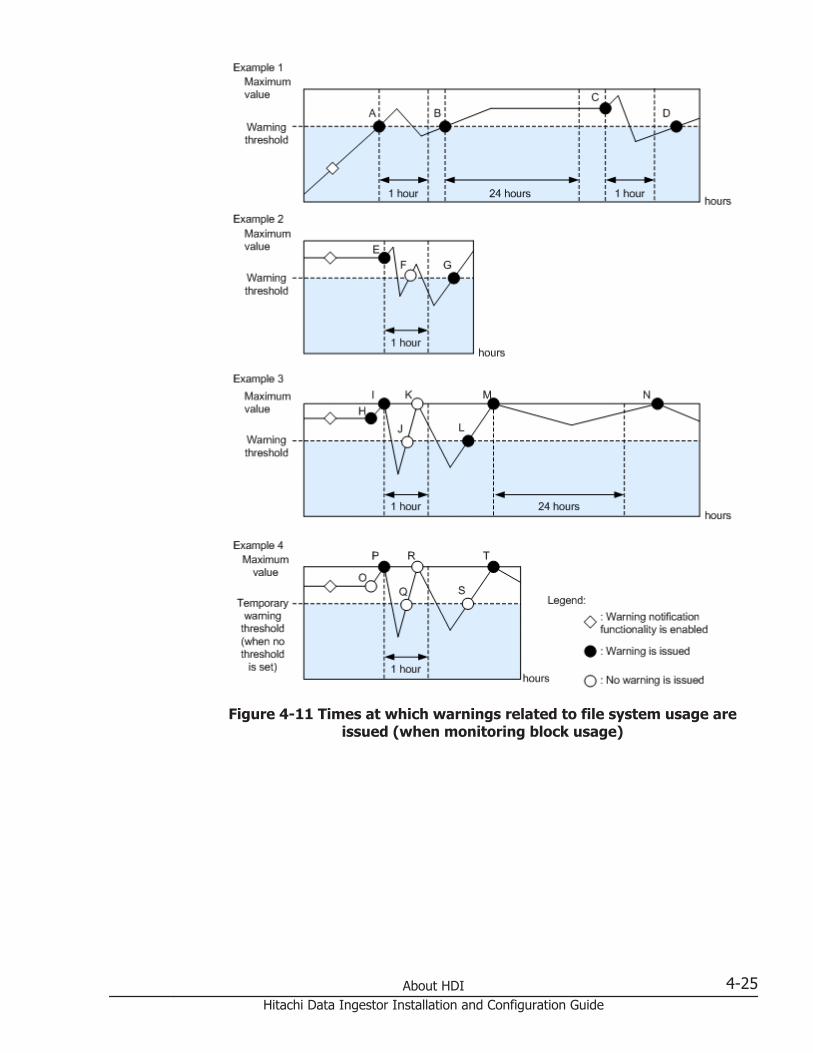
Figure 4-11 Times at which warnings related to file system usage areissued (when monitoring block usage)
About HDI 4-25Hitachi Data Ingestor Installation and Configuration Guide
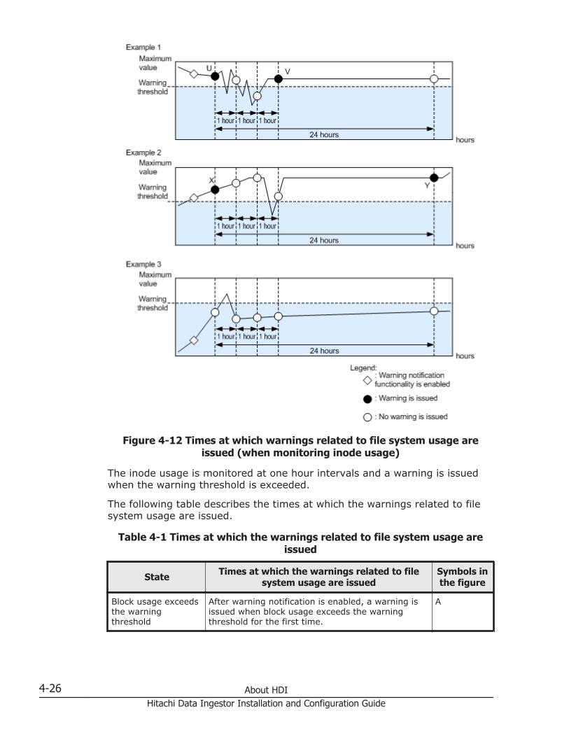
Figure 4-12 Times at which warnings related to file system usage areissued (when monitoring inode usage)
The inode usage is monitored at one hour intervals and a warning is issuedwhen the warning threshold is exceeded.
The following table describes the times at which the warnings related to filesystem usage are issued.
Table 4-1 Times at which the warnings related to file system usage areissued
State Times at which the warnings related to filesystem usage are issued
Symbols inthe figure
Block usage exceedsthe warningthreshold
After warning notification is enabled, a warning isissued when block usage exceeds the warningthreshold for the first time.
A
4-26 About HDIHitachi Data Ingestor Installation and Configuration Guide

State Times at which the warnings related to filesystem usage are issued
Symbols inthe figure
If block usage exceeds the warning threshold whilewarning notification is enabled, a warning is issuedwhen the file system is used.
E, H
A warning is issued when both of the followingconditions are satisfied:
• At least one hour has passed since a previouswarning was issued because the warningthreshold was exceeded. #1
• Block usage exceeds the warning threshold.
B, D, G, L
A warning is issued when both of the followingconditions are satisfied:
• After a previous warning was issued becausethe warning threshold was exceeded, thewarning threshold continued to be exceeded forat least 24 hours.
• The file system was used.
C
Block usage reachesthe maximum value
After warning notification is enabled, a warning isissued when block usage reaches the maximumvalue for the first time.
I, P
A warning is issued when both of the followingconditions are satisfied:
• At least one hour has passed since a previouswarning was issued because block usagereached the maximum value. #1
• Block usage went below the warning thresholdand then reached the maximum value again.#2
M, T
A warning is issued when both of the followingconditions are satisfied:
• After a previous warning was issued becauseblock usage reached the maximum value, blockusage continued to exceed the threshold valuefor at least 24 hours.
• Block usage reached the maximum valueagain.
N
Inode usage exceedsthe warningthreshold
After warning notification is enabled, a warning isissued when inode usage is monitored and exceedsthe warning threshold for the first time.
U, X
The inode usage did not exceed the warningthreshold, but one hour later, inode usage ismonitored and exceeds the warning threshold.
V
A warning is issued when both of the followingconditions are satisfied:
• After a previous warning was issued becausethe warning threshold was exceeded, wheninode usage is monitored, the warning
Y
About HDI 4-27Hitachi Data Ingestor Installation and Configuration Guide
State Times at which the warnings related to filesystem usage are issued
Symbols inthe figure
threshold continued to be exceeded for at least24 hours.
• When inode usage is monitored, the warningthreshold is exceeded.
Note: Regardless of the situation, the warning notification state is reset to thefirst state if any of the following operations are performed:
• Warning notification is disabled and then enabled again.
• The warning threshold is changed.
• The file system is unmounted and then mounted again.
• After the warning threshold is specified with a percentage (%), the filesystem is expanded. (The warning threshold is re-calculated.)
#1:After a warning has been issued, the same warning is not issued until onehour passes (F, J, K, and R in the figure).
#2:If the warning threshold is 0, a dummy warning threshold is set to judgewhether block usage went below the warning threshold after reaching themaximum value. A warning is not issued even when block usage exceedsthe dummy warning threshold (O, Q, and S in the figure).
When the striping function is usedAn HDI system enables you to create file systems by using a volumemanager's striping function.
Overview of the striping function
Striping is one of the functions a volume manager (LVM) provides. Thisfunction enables you to divide contiguous data blocks of a file system intoblocks of a desired size, and then evenly spread out the blocks acrossmultiple device files. Because the number of divided data blocks is equal tothe number of stripes and I/O processing is performed on the device files inparallel, access speed to a disk drive might be improved.
The following figure shows how the data blocks are assigned when thestriping function is used. The number of stripes is equal to the number ofdevice files that were specified when the file system was created. Also, datablocks are assigned by the order of specified device files. In the followingexample, device files are specified in the order of lu00, lu01, lu02, and thenlu03.
4-28 About HDIHitachi Data Ingestor Installation and Configuration Guide

Figure 4-13 Example of the striping function
The following figure illustrates how data blocks are assigned when thecapacity of a striped file system has expanded. The number of stripesremains the same, even when you expand the capacity of a file system.
About HDI 4-29Hitachi Data Ingestor Installation and Configuration Guide

Figure 4-14 Example of the striping function when expanding a file system
If you specify lu00 and lu01 for the creation of a file system, and thenspecify lu02 and lu03 in order to expand the file system, lu00 and lu02 willbecome one stripe, and lu01 and lu03 will become another stripe.
Notes on the striping function
Note the following when using a volume manager striping function:
• When creating or expanding a file system, specify device files of the samesize.
• When expanding a file system, the number of device files and the numberof stripes must be the same.
• Make sure that the device files with which you create a file system belongto different parity groups. If you create a file system with device filesfrom the same parity group, access performance might not improve whenstriping is used.
Selecting which ACL type to use for a file systemThe HDI system allows you to specify access control lists (ACLs) for files anddirectories. The HDI system provides two ACL types for file systems: the
4-30 About HDIHitachi Data Ingestor Installation and Configuration Guide

Advanced ACL type, in which ACLs conforming to NTFS ACLs can be specified,and the Classic ACL type, in which ACLs conforming to POSIX ACLs can bespecified.
When creating a file system, the system administrator must select the ACLtype to be used for the file system. When you want to use only the NFSprotocol for a file share in the file system, we recommend you create a filesystem that uses the Classic ACL type. When you want to use both the CIFSprotocol and the NFS protocol or use only the CIFS protocol, we recommendyou create a file system that uses the Advanced ACL type.
Note the following when accessing a file system of either ACL type from anNFS client:
• In a file system that uses either ACL type, when a client copies a file byusing the NFSv2 or NFSv3 protocol, the file will be copied without the ACLinformation. If a client copies a file by using the NFSv4 protocol, whetherthe ACL information is copied with the file depends on the environmentsettings of the client.
• File systems of the Advanced ACL type cannot be accessed via the NFSv2protocol.
• Which users can execute the chgrp command on an NFS client dependson the ACL type used by the file system:
Advanced ACL typeThe root user and users with the owner permission can execute thecommand.
Classic ACL typeOnly the root user can execute the command.
• When you create a symbolic link by executing the ln command from anNFS client, the permission mode that is assigned to the symbolic link filedepends on the ACL type used by the file system:
Advanced ACL typeThe access control entry (ACE) of the parent directory determines theassigned permission mode.
Classic ACL typeThe fixed value 777 is always assigned.
Also, the access permission of a symbolic link file is based on thepermission mode of the target file, not the permission mode of thesymbolic link file itself.
• From a Solaris 10 or HP-UX 11i v3 NFS client using the NFSv4 protocol, ifthe command used to view Advanced ACLs is executed on a file whoseAdvanced ACL was set by a user or group not managed by the HDIsystem, an error might occur. For example, if you execute the lscommand without any options on an Advanced ACL type file system, thecommand results will be properly displayed. However, if you execute thels command with the -l option, the command will end with an error.
• By using the NFSv4 protocol, ACLs can be viewed or set up from an NFSclient. However, the number of specifiable ACEs on a Linux NFS client
About HDI 4-31Hitachi Data Ingestor Installation and Configuration Guide

might be less than the normal limit for HDI system ACEs. As a result, youmight not be able to specify ACEs from a Linux NFS client. For details onthe maximum number of specifiable ACEs, see Table 4-2 Differencesbetween file systems that use the Advanced ACL type and the Classic ACLtype on page 4-32.
The following table lists the differences between file systems that use theAdvanced ACL type and the Classic ACL type.
Table 4-2 Differences between file systems that use the Advanced ACLtype and the Classic ACL type
Item Advanced ACL type Classic ACL type
Specification to which theACL type conforms
NTFS ACL#1 POSIX ACL
Owner of files or directories User or group User
Maximum number ofACEs#2
700 128 (The maximum numberof ACEs in the access ACLand default ACL is 64 each.)
ACE type Allow or Deny Allow
Access permissions to beset#3
• Full Control
• Traverse Folder/ExecuteFile
• List Folder/Read Data
• Read Attributes
• Read Extended Attribute
• Create Files/Write Data
• Create Folders/AppendData
• Write Attributes
• Write ExtendedAttributes
• Delete Subfolders andFiles
• Delete
• Read Permissions
• Change Permissions
• Take Ownership
• Read
• Write
• Execute
ACL to be set when a newfile or directory is created
ACL that was inherited fromthe parent directory
Initial permission specifiedwhen a CIFS share iscreated, if the ACL that wasinherited from the parentdirectory is not set.
Initial permissions that werespecified when a CIFS sharewas created
File attributes that can beset
(DOS attributes)
• Read only
• Archive
• Directory
• Read only
• Directory
4-32 About HDIHitachi Data Ingestor Installation and Configuration Guide

Item Advanced ACL type Classic ACL type
• Hidden file
• System file
#1:The HDI system only supports discretionary access control lists (DACLs).Accordingly, the standard Windows audit functionality cannot be used.Use the CIFS access log files provided by the HDI system.
#2:Although more than 700 ACEs can be set in a Windows NTFS ACL, themaximum number of ACEs that can be set in a file system provided by anHDI system is 700 or 128 (the maximum number of ACEs in the accessACL and default ACL is 64 each).
#3:When you set an NFSv4 ACL from NFS clients, the appropriate accesspermissions are mapped from the NFSv4 ACL according to what type ofACL is used in the file system.
Migrating to a file system that uses the Advanced ACL typeThe HDI system allows you to migrate a file system that uses the Classic ACLtype to a file system that uses the Advanced ACL type.
The method for evaluating Allow access permissions differs between filesystems that use the Classic ACL type and the Advanced ACL type as follows:
When a file system uses the Advanced ACL type:A user's access permissions are based on the permissions granted toothers (Everyone) or the group to which the user belongs, regardless ofwhether those permissions are granted to the individual user. Forexample, when write permission is granted to others (Everyone) or agroup to which the user belongs, the user will now also have writepermission, even if they were not specifically targeted.
When a file system uses the Classic ACL type:A user's access permissions are only based on the permissions granted tothe user. For example, when only read-only permission is granted to theuser, even if write permission is granted to others (Everyone) or thegroup to which the user belongs, the user will not have the writepermission.
Because the evaluation methods of the user permissions differ as describedabove, in order to prevent the access permissions of users and groups thathave less permission than the others (Everyone) before a migration frombeing increased to the same permission as the others (Everyone) after themigration, Deny ACEs are added. This occurs in the following situations:
About HDI 4-33Hitachi Data Ingestor Installation and Configuration Guide

• When the access permissions (selected in Permissions displayed in theWindows Properties window) of a user and the group to which the userbelongs are less than those for others (Everyone)
• When the access permissions (selected in Permissions displayed in theWindows Properties window) of the user are less than those for the groupto which the user belongs
In addition, the information displayed in Permissions of the WindowsProperties window might differ before and after a file system migration. Forexample, even if Full Control is displayed before migration, Special mightbe displayed after migration.
ACLs might differ before and after migration because ACLs are convertedbased on the ACL inheritance relationship and access permissions that werespecified for file systems that use the Classic ACL type. If the converted ACLsare different from the ones intended for the CIFS client that is using the filesand directories, the ACLs must be reconfigured for the file system after themigration. Before deciding whether to migrate a file system, the systemadministrator needs to check the notes on migrating a file system.
After a file system has been migrated, the ACLs for the file system arecreated with precedence given to making sure that the access permissions forfiles or directories do not change, rather than making sure that the accesspermissions can be visually confirmed from the client. Depending on the typeof client ACL operation, operations on a file system might become difficultbecause of the difference in the visual display of the access permissions aftermigration.
For detailed notes on migrating a file system that uses the Classic ACL typeto a file system that uses the Advanced ACL type, see Notes on migrating afile system on page 4-35.
Reference:In the rest of this subsection, access permissions are represented in thefollowing format:octal-notation-of-access-permission(abbreviation-of-access-permission)The following table shows how access permissions are represented.
Table 4-3 How access permissions are represented
Octalnotation of
accesspermissions
Abbreviationof access
permissionsDescription
7 rwx Access permissions allowing reading, writing, andexecution
6 rw- Access permissions allowing reading and writing
5 r-x Access permissions allowing reading and execution
4 r-- Access permissions allowing reading only
4-34 About HDIHitachi Data Ingestor Installation and Configuration Guide
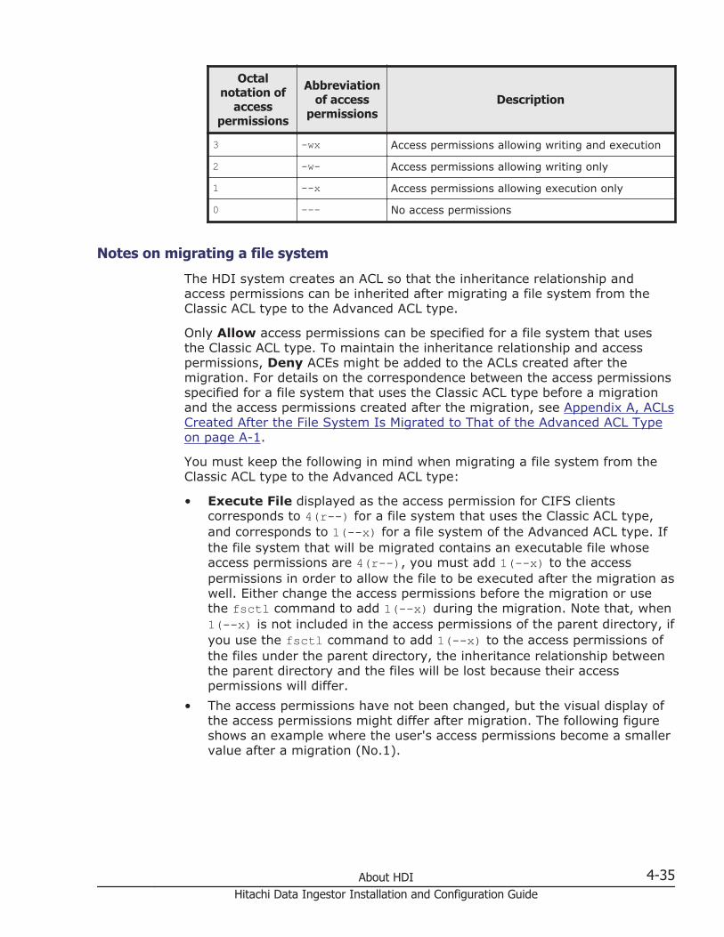
Octalnotation of
accesspermissions
Abbreviationof access
permissionsDescription
3 -wx Access permissions allowing writing and execution
2 -w- Access permissions allowing writing only
1 --x Access permissions allowing execution only
0 --- No access permissions
Notes on migrating a file system
The HDI system creates an ACL so that the inheritance relationship andaccess permissions can be inherited after migrating a file system from theClassic ACL type to the Advanced ACL type.
Only Allow access permissions can be specified for a file system that usesthe Classic ACL type. To maintain the inheritance relationship and accesspermissions, Deny ACEs might be added to the ACLs created after themigration. For details on the correspondence between the access permissionsspecified for a file system that uses the Classic ACL type before a migrationand the access permissions created after the migration, see Appendix A, ACLsCreated After the File System Is Migrated to That of the Advanced ACL Typeon page A-1.
You must keep the following in mind when migrating a file system from theClassic ACL type to the Advanced ACL type:
• Execute File displayed as the access permission for CIFS clientscorresponds to 4(r--) for a file system that uses the Classic ACL type,and corresponds to 1(--x) for a file system of the Advanced ACL type. Ifthe file system that will be migrated contains an executable file whoseaccess permissions are 4(r--), you must add 1(--x) to the accesspermissions in order to allow the file to be executed after the migration aswell. Either change the access permissions before the migration or usethe fsctl command to add 1(--x) during the migration. Note that, when1(--x) is not included in the access permissions of the parent directory, ifyou use the fsctl command to add 1(--x) to the access permissions ofthe files under the parent directory, the inheritance relationship betweenthe parent directory and the files will be lost because their accesspermissions will differ.
• The access permissions have not been changed, but the visual display ofthe access permissions might differ after migration. The following figureshows an example where the user's access permissions become a smallervalue after a migration (No.1).
About HDI 4-35Hitachi Data Ingestor Installation and Configuration Guide

Figure 4-15 Example where the user's access permissions decreaseafter a migration (No.1)
If a user belongs to a group whose access permissions are lower than thatfor others (Everyone), and the user's access permissions are higher thanthat of the group, Deny ACEs will be added to the group after migration.In a file system that uses the Advanced ACL type, because Deny ACEsare evaluated before Allow ACEs, the user's access permissions willdecrease after a migration.
• If the migration affects the access permissions of a file system, ACLs willbe created in such a way that the access permissions become morelimited. The following figure shows an example where the user's accesspermissions will decrease after a migration (No.2).
4-36 About HDIHitachi Data Ingestor Installation and Configuration Guide

Figure 4-16 Example where the user's access permissions decreaseafter a migration (No.2)
If a user belongs to multiple groups whose access permissions are lowerthan that for others (Everyone), and each group has different permissionsfor files not owned by the user, the user's access permissions willdecrease after a migration.
• If you migrate a file system, information displayed in Permissions of theWindows Properties window might differ before and after migration. Forexample, if the access permissions are set to 7(rwx) for a file system thatuses the Classic ACL type, the information is displayed so that FullControl permission is granted, however, after migration, the displayedinformation changes so that only Delete is not allowed.
• The NFSv2 protocol is not available for file systems that use the AdvancedACL type. Make sure that no clients are using the NFSv2 protocol for thefile system after a migration.
• The HDI system allows quota information to be inherited after themigration of a file system from the Classic ACL type to the Advanced ACLtype.
Estimating the file system size after a migration
Migrating a file system of the Advanced ACL type increases the amount ofinformation in the ACEs, thus increasing the file system size. Normally, in afile system of the Advanced ACL type, an ACE uses a 4 KB for a file or adirectory. The system administrator must allocate sufficient free area beforemigrating the file system.
About HDI 4-37Hitachi Data Ingestor Installation and Configuration Guide

An ACE might use up to 64 KB for a file or directory. If too many ACEs havebeen specified for a file system of the Classic ACL type, take the ACEs intoconsideration when estimating the file system size.
How to migrate a file system
If a file system that will be migrated contains an executable file whose accesspermissions are 4(r--) (a file that can be executed from a CIFS client), youwill no longer be able to execute the file after the migration. The systemadministrator needs to request the file owner to change the accesspermissions before migration, or use the fsctl command to change theaccess permissions of the file.
Executing the fsctl command automatically changes the access permissionsof a file of a specified extension. If the system administrator cannot identifythe file extension, or if there are settings only allow the file owner to changethe access permissions of the file, request the file owner to change the accesspermissions.
The following describes the procedure for migrating a file system that usesthe Classic ACL type to a file system that uses the Advanced ACL type.
To migrate a file system:
1. Contact the end users.Ask the end users to not access the file system during this task.Also, ask beforehand if the file owner needs to change the accesspermissions of any executable files whose access permissions are 4(r--).
2. Back up the file system you want to migrate.
3. Add 1(--x) to the access permissions of executable files.
Use the fsctl command to add 1(--x) to the access permissions ofexecutable files whose access permissions are 4(r--) in order to enablethe files to be executed after migration.
$ sudo fsctl -c -x -o add_exeauth filesystem03/unit15filesystem03/unit15: Wait ............. Success
4. Save the file share settings.Use the cifslist or nfslist command to check, and then save the fileshare settings for the file system that will be migrated.
$ sudo cifslist -v -O allList of File Shares:The number of CIFS share(1) Name of file share : unit15 Shared directory : /mnt/filesystem03/unit15 Use ACL : use Server specification : -- Comment for file share : Permission mode : rw Browse permission : permit File access permissions : rw,rw,rw Directory access permissions : rw,rw,rw Write disallowed users : sys04 Write disallowed groups : -- Write allowed users : --
4-38 About HDIHitachi Data Ingestor Installation and Configuration Guide

Write allowed groups : -- Guest account access : default Disk synchronization policy : default CIFS client cache : default File timestamp changeable : default Home directory : do_not_use CIFS access log (success) : none CIFS access log (failure) : none ACL type : Classic ACL Client access policy : parallel Volume Shadow Copy Service : default Read-only cache for conflicts : default Access Based Enumeration : default
$ sudo nfslist -O allList of File Shares:The number of NFS share(1) Shared directory : /mnt/filesystem03/unit14 Public destination host/network : host01 Permission mode / Synchronous writing : rw_sync Anonymous mapping : root_only Anonymous UID : 65534 Anonymous GID : 65534 Transmission port restriction : do_not_perform Subtree check : do_not_perform Access check with lock request : do_not_perform Maximum rwsize(KB) : -- Host/network name resolution : OK Security flavor : sys,krb5i
5. Release all the file shares.Use the cifsdelete or nfsdelete command to release all the file sharesin the file system.
$ sudo cifsdelete -x unit15$ sudo nfsdelete -d /mnt/filesystem03/unit14 -a
6. Unmount the file system.Use the fsumount command to unmount the file system.
$ sudo fsumount filesystem03
7. Change the ACL type of the file system to the Advanced ACL type, andthen mount the file system.Use the fsmount command to change the ACL type of the file systemfrom the Classic ACL type to the Advanced ACL type, and then mount thefile system.
$ sudo fsmount -w -c filesystem03
8. Convert the ACL type of the files to the Advanced ACL type.Use the fsctl command to convert the ACL type of the directories andfiles from the Classic ACL type to the Advanced ACL type.
$ sudo fsctl -c -x -o advanced_acl filesystem03filesystem03: Wait ............. Success
Note:
About HDI 4-39Hitachi Data Ingestor Installation and Configuration Guide
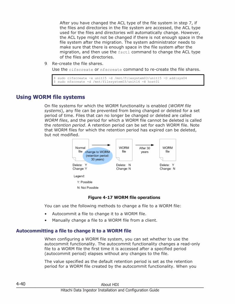
After you have changed the ACL type of the file system in step 7, ifthe files and directories in the file system are accessed, the ACL typeused for the files and directories will automatically change. However,the ACL type might not be changed if there is not enough space in thefile system after the migration. The system administrator needs tomake sure that there is enough space in the file system after themigration, and then use the fsctl command to change the ACL typeof the files and directories.
9. Re-create the file shares.Use the cifscreate or nfscreate command to re-create the file shares.
$ sudo cifscreate -x unit15 -d /mnt/filesystem03/unit15 -D add:sys04$ sudo nfscreate -d /mnt/filesystem03/unit14 -H host01
Using WORM file systemsOn file systems for which the WORM functionality is enabled (WORM filesystems), any file can be prevented from being changed or deleted for a setperiod of time. Files that can no longer be changed or deleted are calledWORM files, and the period for which a WORM file cannot be deleted is calledthe retention period. A retention period can be set for each WORM file. Notethat WORM files for which the retention period has expired can be deleted,but not modified.
Figure 4-17 WORM file operations
You can use the following methods to change a file to a WORM file:
• Autocommit a file to change it to a WORM file.
• Manually change a file to a WORM file from a client.
Autocommitting a file to change it to a WORM file
When configuring a WORM file system, you can set whether to use theautocommit functionality. The autocommit functionality changes a read-onlyfile to a WORM file the first time it is accessed after a specified period(autocommit period) elapses without any changes to the file.
The value specified as the default retention period is set as the retentionperiod for a WORM file created by the autocommit functionality. When you
4-40 About HDIHitachi Data Ingestor Installation and Configuration Guide

manually change a file for which the autocommit period has not elapsed to aWORM file, the value specified from a client is set as the retention period.
Manually changing a file to a WORM file from a client
You can change a file to a WORM file by changing the last access date andtime of the file (atime) to the retention end time, and setting the file to read-only.
Change atime so that the period of time from the date and time when the fileis changed to read-only until the retention end date and time is within therange of the minimum and maximum retention periods that were specifiedwhen the WORM file system was configured.
To change atime from a client, the user must create their own customapplication. For details about the API used to create custom applications forWORM operations, see the File System Protocols (CIFS/NFS) Administrator'sGuide.
After a file is changed to a WORM file, the retention period can be extendedby changing atime. For files for which the retention period has expired, youcan set the retention period again by canceling the read-only attribute,changing atime to the retention end time, and then setting the read-onlyattribute again. Note that WORM files for which the retention period hasexpired can be deleted, but not changed.
If you change a file to a WORM file or change the retention period from anNFSv4 client using Linux, use Linux kernel version 2.6.35 or later, or applythe following patch:
Patch nameNFSv4: Fix an embarassing typo in encode_attrs()
Commit IDd3f6baaa34c54040b3ef30950e59b54ac0624b21
If the period of time from when a file is set to read-only until the retentionend time is not within the range of the minimum and maximum retentionperiods, the following settings are configured:
• If the period of time from when read-only was set until the specifiedretention end time is greater than the maximum retention period, themaximum retention period is used as the retention period.
• If the period of time from when read-only was set until the specifiedretention end time is less than the minimum retention period, theminimum retention period is used as the retention period.
• If read-only is set more than 24 hours after the specified retention endtime, system operation is affected as noted below. System operation isaffected differently when the maximum retention period is set to infinite:
¢ If the maximum retention period is infinite, the retention period isalso infinite.
¢ If the maximum retention period is not infinite, the file is not changedto a WORM file.
About HDI 4-41Hitachi Data Ingestor Installation and Configuration Guide

• If read-only is set 24 hours or less after the specified retention end time,the file is not changed to a WORM file.
Precautions regarding WORM file system operation
Keep the following in mind for WORM file system operation:
• Once a file system is created, whether the WORM functionality is enabledcannot be changed for the file system.
• To change the name of a directory in a WORM file system, set the WORMsettings of the file system to allow the names of empty directories to bechanged. Note that the default settings for WORM file systems that havebeen set up in version 4.0.0-00 or later do not allow directory names tobe changed.
• ACL types cannot be changed after a WORM file system is set up.
• atime is not updated when a WORM file for which the retention period hasnot expired is accessed.
• Even if the creation time of a file is set to be recorded in a WORM filesystem, the creation time of the WORM file is not recorded.
• You cannot delete a file system that contains a WORM file whoseretention period has not expired.
• Empty files of 0 bytes cannot be changed to WORM files.
• If a WORM file system has been restored on an HDI system from datamigrated to an HCP system, files for which the retention periods have notexpired are not turned into WORM files until the files are accessed to bedeleted or changed.
Using single instancing to reduce used capacityIn an HDI system, you can reduce used disk capacity by creating a singleinstance of multiple files that have the same content. This technique can beused to efficiently reduce used disk capacity when multiple clients are usingcopies of large files, such as presentations with videos and images.
Keep the following in mind when using single instancing:
• After a file system is configured to use single instancing, the configurationcannot be changed back.
• For a file system configured to use single instancing, a maximum of 10 KBin the management area is required per file. Take this into account whenconsidering the file system capacity.
• Set a policy (single-instancing policy) so that the data of files that areupdated less frequently are single instanced. If the data of frequently-updated files is single instanced, the used disk capacity might not bereduced. The single-instancing policy can be set in the TaskManagement dialog box or from the Single Instancing Wizard.
• Files which meet any of the following conditions cannot be singleinstanced.
¢ The file capacity is 16 KB or less.
4-42 About HDIHitachi Data Ingestor Installation and Configuration Guide

¢ The file path contains a line feed code.
¢ Files that have the following names and that are located directlyunder the file system:.backupdates, .temp_backupdates
• Executing single-instancing tasks might take a lot of time for files with acapacity of 16 KB or less, or when the number of excluded files that aresingle instanced due to the single-instancing policy that was set in theTask Management dialog box is large. In such cases, use thearcfilterpolicyset command and add file conditions (filtering policy) tobe excluded from being single instanced. Setting the filtering policydeletes the files that have old last-modification times (mtime) in the taskmanagement information, and might improve the task execution time.
• File systems created by HDI systems whose versions are earlier than3.0.5 cannot be single instanced.
• Make sure that migration tasks and single-instancing tasks are notexecuted on a single file simultaneously. If different tasks are executedsimultaneously, an error appears. The next time the tasks are executed,they are processed correctly.
Using CIFS bypass traverse checkingThe CIFS bypass traverse checking functionality enables the user to accessCIFS by specifying an absolute path to the target object (such as a directoryor a file) where the user has access permission, regardless of not havingaccess permission to the higher-level directories.
The following shows an example of the objects./mnt/fs01/dir1/dir12/access.txtIn this case, if the user does not have access permission to the dir1 anddir12 directories but has access permission to the access.txt file, the usercan access the access.txt file by specifying its absolute path.
The CIFS bypass traverse checking functionality can be enabled or disabledfor each file system.
If the CIFS bypass traverse checking functionality is disabled, in the HDIsystem, the user needs to have the Traverse Folder/Execute File permission(file permissions are 1 (--x) for Advanced ACL type, and 4 (r--) for ClassicACL type) for all the higher-level directories to access the target object. Also,if different administrators are assigned according to the directory structure,you need to ask the administrator of each directory to change the ACLconfiguration.
Other than that stated above, the following are several things to note:
• For version 4.2.0-00 and later, CIFS bypass traverse checking is enabledby default when the file system is created. However, the CIFS bypasstraverse checking is disabled for the home-directory-roaming filesystems.
About HDI 4-43Hitachi Data Ingestor Installation and Configuration Guide

• Differential-data snapshots depend on whether the snapshots are createdin the file system with CIFS bypass traverse checking enabled. The CIFSbypass traverse checking cannot be enabled or disabled for eachdifferential-data snapshot that was created.
• When update installation is performed to the HDI system of a versionearlier than 4.2.0-00, the CIFS bypass traverse checking for each filesystem becomes disabled.
• If the system is restored by using the system configuration informationthat was stored in the system LU of a version earlier than 4.2.0-00, theCIFS bypass traverse checking becomes disabled.
• If data that was migrated on the HCP system by a system with a versionearlier than 4.2.0-00 is restored to a file system where CIFS bypasstraverse checking was enabled by using the arcrestore command, theCIFS bypass traverse checking becomes enabled.
Change the file system settings, if necessary.
About setting quotasThe HDI system also provides quota management for each file system oreach directory. In the HDI system, quotas set for individual directories arecalled subtree quotas.
Managing quotas for each file systemManaging quotas for each file system enables the system administrator toset file system-specific quotas for users and groups, as well as set thedefault quota for a file system.
Managing subtree quotasSubtree quotas enable the system administrator to manage quotas foreach directory of a file system. Managing subtree quotas enables thesystem administrator to set quotas on directories for users and groups, aswell as set quotas or default quotas for directories.A subtree quota can be set for any directory in a file system. You can setsubtree quotas in up to three locations anywhere in a directory tree aslong as the locations are in a range of directories that have a parent-childrelationship from the highest level to the lowest level. When using theGUI, you can set quotas for directories immediately under a mount pointby managing the file share capacity.If multiple file shares are to be created for a single file system, setting thesubtree quota for a shared directory immediately below the mount pointenables you to flexibly manage the capacity of each file share. Quotas canbe specified for a maximum of 1,023 directories in a file system. Notethat there is no upper limit for the number of users or groups that can setquotas.
4-44 About HDIHitachi Data Ingestor Installation and Configuration Guide
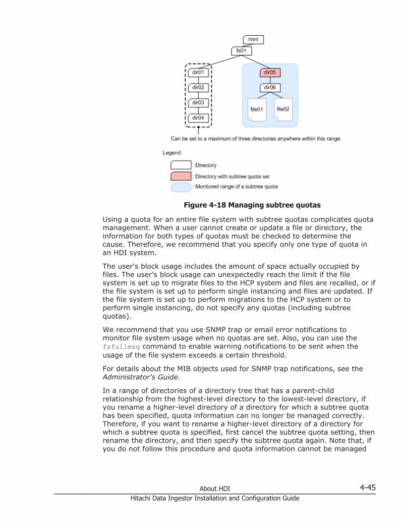
Figure 4-18 Managing subtree quotas
Using a quota for an entire file system with subtree quotas complicates quotamanagement. When a user cannot create or update a file or directory, theinformation for both types of quotas must be checked to determine thecause. Therefore, we recommend that you specify only one type of quota inan HDI system.
The user's block usage includes the amount of space actually occupied byfiles. The user's block usage can unexpectedly reach the limit if the filesystem is set up to migrate files to the HCP system and files are recalled, or ifthe file system is set up to perform single instancing and files are updated. Ifthe file system is set up to perform migrations to the HCP system or toperform single instancing, do not specify any quotas (including subtreequotas).
We recommend that you use SNMP trap or email error notifications tomonitor file system usage when no quotas are set. Also, you can use thefsfullmsg command to enable warning notifications to be sent when theusage of the file system exceeds a certain threshold.
For details about the MIB objects used for SNMP trap notifications, see theAdministrator's Guide.
In a range of directories of a directory tree that has a parent-childrelationship from the highest-level directory to the lowest-level directory, ifyou rename a higher-level directory of a directory for which a subtree quotahas been specified, quota information can no longer be managed correctly.Therefore, if you want to rename a higher-level directory of a directory forwhich a subtree quota is specified, first cancel the subtree quota setting, thenrename the directory, and then specify the subtree quota again. Note that, ifyou do not follow this procedure and quota information cannot be managed
About HDI 4-45Hitachi Data Ingestor Installation and Configuration Guide
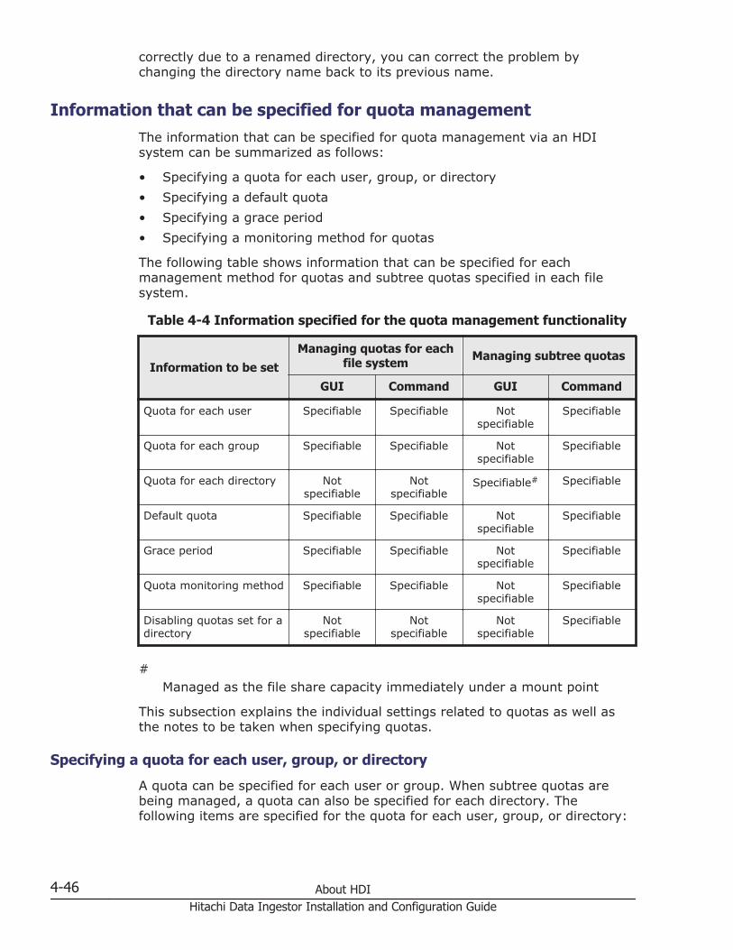
correctly due to a renamed directory, you can correct the problem bychanging the directory name back to its previous name.
Information that can be specified for quota managementThe information that can be specified for quota management via an HDIsystem can be summarized as follows:
• Specifying a quota for each user, group, or directory
• Specifying a default quota
• Specifying a grace period
• Specifying a monitoring method for quotas
The following table shows information that can be specified for eachmanagement method for quotas and subtree quotas specified in each filesystem.
Table 4-4 Information specified for the quota management functionality
Information to be setManaging quotas for each
file system Managing subtree quotas
GUI Command GUI Command
Quota for each user Specifiable Specifiable Notspecifiable
Specifiable
Quota for each group Specifiable Specifiable Notspecifiable
Specifiable
Quota for each directory Notspecifiable
Notspecifiable
Specifiable# Specifiable
Default quota Specifiable Specifiable Notspecifiable
Specifiable
Grace period Specifiable Specifiable Notspecifiable
Specifiable
Quota monitoring method Specifiable Specifiable Notspecifiable
Specifiable
Disabling quotas set for adirectory
Notspecifiable
Notspecifiable
Notspecifiable
Specifiable
#Managed as the file share capacity immediately under a mount point
This subsection explains the individual settings related to quotas as well asthe notes to be taken when specifying quotas.
Specifying a quota for each user, group, or directory
A quota can be specified for each user or group. When subtree quotas arebeing managed, a quota can also be specified for each directory. Thefollowing items are specified for the quota for each user, group, or directory:
4-46 About HDIHitachi Data Ingestor Installation and Configuration Guide

Hard limitYou can specify an upper limit (hard limit) on the block capacity and thenumber of inodes available to a user, group, or directory. If the hard limitis exceeded, it is no longer possible to allocate a new block or create a fileor directory.
Soft limitYou can specify a warning value (soft limit) on the block capacity and thenumber of inodes available to a user, group, or directory. If the soft limitis exceeded, and a fixed duration (grace period) has elapsed, it is nolonger possible to allocate a new block or create a file or directory.When a user or group is no longer able to create or update files, the useror group must delete files until both block and inode usage falls below thesoft limits, upon which files can be created or updated again.The value specified for a soft limit must be equal to or less than the valuespecified for a hard limit.
When you use the GUI to specify the file share capacity, only the hard limit(i.e., the limit on the block capacity) is set for the directory.
Specifying a default quota
The default quota prevents users that do not have a quota from overusingblock capacity and inodes. Hard and soft limits can be specified using amethod similar to the method that is used for specifying a quota for eachuser or group.
The value specified for the default quota is applied when a user, for whom aquota has not been specified, uses a file system or directory for the first timethat has the default quota (i.e. when the user creates the file).
The default quota is applied to all users, including users registered by usermapping.
Specifying a grace period
You can specify a fixed duration (grace period) to allow a user or group tocreate a file and allocate blocks after that user or group has exceeded thesoft limit.
Specifying a quota monitoring method
Quota information is monitored at specified times. You can use SNMP trapsnotifications, email notifications, or the management.log file to viewinformation on any users or groups that have exceeded the soft limit or graceperiod.
The quota monitoring times and the SNMP trap notification mode (when usersor groups exceeding the soft limit or grace period are detected) can bespecified for each file system. If a quota is specified, the disk usage will berestricted when either the specified hard limit or grace period is reached,regardless of the quota monitoring time.
About HDI 4-47Hitachi Data Ingestor Installation and Configuration Guide

There are two SNMP trap notification modes:
Summary notification mode (recommended)If a state that exceeds the soft limit or grace period is detected for users,groups, or directories, the number of such users, groups, or directories isreported. The management.log file and the email notification contain thesame information as the summary notification.
Individual notification modeIf a state that exceeds the soft limit or grace period is detected for users,groups, or directories, the quota information of each of the users, groups,or directories will be reported. If the number of users, groups, ordirectories exceeding the soft limit or grace period exceeds 100,respectively, the individual notifications are suppressed, and only thenumber of users, groups, or directories exceeding the soft limit or graceperiod will be reported to the SNMP manager. When managing subtreequotas, the individual notification mode is not available for quotasspecified for users and groups.
The following table lists the information items reported if an exceeded softlimit or grace period is detected.
Table 4-5 Information reported if an exceeded soft limit or grace period isdetected
Item Summarynotification
Individual notification
When a softlimit is
exceeded
When agrace periodis exceeded
When theindividual
notificationmode is
suppressed
Notification time Yes Yes Yes Yes
Host name Yes Yes Yes Yes
Node number Yes Yes Yes Yes
Device identificationnumber
Yes Yes Yes Yes
File system name Yes#1 Yes#2 Yes#2 Yes
Managementtype#3
-- Yes Yes Yes
User name or groupname
-- Yes Yes --
User ID or group ID -- Yes Yes --
Type of limitexceeded (block/inode)
-- Yes Yes --
Current usage
(units of blockusage: KB)
-- Yes Yes --
4-48 About HDIHitachi Data Ingestor Installation and Configuration Guide

Item Summarynotification
Individual notification
When a softlimit is
exceeded
When agrace periodis exceeded
When theindividual
notificationmode is
suppressed
Soft limit value
(units of blockusage: KB)
-- Yes Yes --
Hard limit value
(units of blockusage: KB)
-- Yes Yes --
Remaining graceperiod
(units: seconds)
-- Yes -- --
Grace period
(units: days)
-- -- Yes --
Number of users,groups, ordirectoriesexceeding the softlimit for blockusage
Yes -- -- Yes
Number of users,groups, ordirectoriesexceeding the graceperiod for blockusage
Yes -- -- Yes
Number of users,groups, ordirectoriesexceeding the softlimit for inodeusage
Yes -- -- Yes
Number of users,groups, ordirectoriesexceeding the graceperiod for inodeusage
Yes -- -- Yes
Legend: Yes = Reported, -- = Not reported
#1:If a subtree quota is set for a user or group, this item is displayed in thefollowing format:file-system-name/directory-name
#2:
About HDI 4-49Hitachi Data Ingestor Installation and Configuration Guide

If a subtree quota is set for a user, group, or directory, this item isdisplayed in the following format:file-system-name/directory-name
#3:If quotas are managed by a file system, either user or group will benotified. If subtree quotas are managed, subtree, subtree_user, orsubtree_group will be notified.
Notes on specifying quotas
Keep the following in mind when specifying quotas:
• Block usage is managed by file systems in 4-KB units. An allocated blockis not only used to write data, but it is also used for system management.As such, even if the total size of some files is less than the block usagelimit, the block usage itself might exceed the limit. For this reason,specify a limit value that is at least 1 MB larger than what is needed.
• There are no user, group, or directory quota or default quota restrictionseither on root users who are not mapped as anonymous users (NFSclients) or on CIFS administrators. Similarly, there are no group quotarestrictions on root group users who are not mapped as anonymous users(NFS clients). In addition, there are no user, group, or directory quota ordefault quota restrictions when the following operations are performed:
¢ Save CIFS access logs. (This includes the automatic collection of logsunder certain conditions.)
¢ Perform a GUI operation or execute a command as a systemadministrator
¢ Use the NDMP functionality to restore data
• When quotas are set both for a specific user and for a group to which thatuser belongs, the smaller of the two quotas is applied. The following tableshows an example of user quota settings.
Table 4-6 Example of user quota settings
User name Quota set for theuser Primary group Groups the user is in
User A 20 GB Group 1 Group 1
User B 20 GB Group 1 Group 1
User C 20 GB Group 1 Group 1
User D 30 GB Group 2 Groups 1 and 2
Using the example above, if the quota set for group 1 is 25 GB, the blockcapacity that each user can use is as follows:A quota of 20 GB is set for users A, B, and C. As such, users A, B, or Ccan only use 20 GB of block capacity. Furthermore, if user A is using 20GB, then users B and C can only use 5 GB of block capacity betweenthem.
4-50 About HDIHitachi Data Ingestor Installation and Configuration Guide

User D can use up to 30 GB of block capacity, assuming that no quota isspecified for user D's primary group (group 2). However, if user Dupdates a group 1 file by using the group's execution permission, thenuser D will be restricted to a 25 GB block capacity, which is the limit forgroup 1.
• Subtree quotas cannot be set for directories whose names contain any ofthe following characters:" * : < > ? \ |
• When a subtree quota for a user (or group) or the default quota has beenspecified for a directory in a range of directories that have a parent-childrelationship from the highest level to the lowest level in a directory tree,you cannot set subtree quotas for directories under that directory.For example, as shown below, if subtree quotas are set to dir01 for theuser, then subtree quotas cannot be set to dir02. If quotas are set todir04 for the directory, quotas can be set to dir03 for the directory, butsubtree quotas for the user or group, or default cannot be set.
Specifying quotas for each file systemWhen many users share a file system, you can specify quotas for users orgroups to prevent them from putting too much of a load on the systembecause they are using too much disk space.
The following shows an example of specifying quotas for this purpose.
About HDI 4-51Hitachi Data Ingestor Installation and Configuration Guide

Figure 4-19 Example of specifying quotas for a file system
For example, you can specify quotas for user11 and group1 in order to limitthe block usage of the FS01 file system.
Specifying subtree quotasWhen you specify directories immediately under the mount point as a filesystem made public to users and groups, you can set a subtree quota foreach shared directory to prevent a particular shared directory from occupyingtoo much space on the entire file system.
When you specify a subtree quota, you can limit the capacity available in thedirectory. This enables you to operate a directory in the same way as a filesystem, allowing you to freely change the capacity.
The following is an example of specifying subtree quotas for these purposes:
4-52 About HDIHitachi Data Ingestor Installation and Configuration Guide

Figure 4-20 Example of setting subtree quotas for directories immediatelyunder the mount point
For example, you can specify quotas for the share1 directory in the FS02 filesystem to limit the available block usage for the directory. You can also setquotas for user21 and group1, which use the share1 directory, to limit theblock usage available in this directory to user21 and group1.
In this example, the available block usage for the share3 directory in theFS02 file system is limited to a maximum of 200 GB, but it can be expandeddepending on the file system operation.
Notes on quota managementNote the following when managing quotas:
• To manage quotas on a file system, the quota functionality must beenabled when the file system is mounted.
• To start quota management for a file system being mounted, unmountthe file system, and then re-mount the file system with the quota
About HDI 4-53Hitachi Data Ingestor Installation and Configuration Guide

functionality enabled. If the capacity of the file system is insufficient forquota management, the quota management functionality cannot be used.The system administrator must either expand the file system or deleteunnecessary files from it in order to increase free space, and then re-mount the file system.Internal system checks take place when a file system is re-mounted. As aresult, the larger the used capacity of a file system, the longer it will taketo mount the file system.
• You can view quota information from the SNMP trap. When too manyusers or groups are registered in the file system, it will take a long timeto view the quota information from the SNMP manager. By directly editingthe /etc/snmp/snmpd.conf file, you can disable the SNMP manager, ifthere is a large number of users and groups registered in the file system.
• If you monitor quota information, response performance throughout theentire HDI system might decrease while the monitoring is beingprocessed.
Also note the following about managing quotas for each file system:
• When File Services Manager is in GUI operation mode, the systemadministrator cannot display the List of Quota Information page of theEdit Quota dialog box in the following environments. Place File ServicesManager in command operation mode or use commands to perform quotamanagement.
¢ An environment in which the total number of users registered by FileServices Manager, the NIS server, and the LDAP server for userauthentication exceeds 10,000
¢ An environment in which the total number of groups registered by FileServices Manager, the NIS server, and the LDAP server for userauthentication exceeds 10,000
• When File Services Manager is in command operation mode, the systemadministrator cannot use the GUI to perform the following operations:
¢ View quota information for a user or group
¢ Specify a user-based or group-based quotaInstead of using the GUI, use commands to perform the aboveoperations.
• Use commands to manage quotas for users and groups registered by usermapping.
• If you specify a quota for users registered by user mapping, werecommend that you specify quota monitoring times.
Note the following when managing subtree quotas:
• You cannot obtain subtree quota information by executing the commandfor obtaining quota information from an NFS client.
• For subtree quota information, clients must contact the systemadministrator.
4-54 About HDIHitachi Data Ingestor Installation and Configuration Guide

Typical example of quota managementThe following figure shows a typical example of quota management.
Figure 4-21 Typical example of quota management
1. DetectionBased on an SNMP trap, an email notification, or the quota informationperiodically acquired by executing a command from a remote host, thesystem administrator detects that HDI system users who are using thefile system have exceeded a quota.
2. InvestigationAfter detecting that a quota has been exceeded, the system administratorchecks the file system usage by using commands to obtain the quota
About HDI 4-55Hitachi Data Ingestor Installation and Configuration Guide
information (including the user names) of those users who have exceededtheir quotas.
3. NotificationThe system administrator checks the quota information and then contactsthe users who have exceeded their quotas.
4. ActionThe system administrator can take either of the following actions,according to the end users' usage of the file system:
¢ Change the quota settings.
¢ Ask users to delete unnecessary data.
By using SNMP trap summary notifications or email notifications together withquota-management commands, the system administrator has acomparatively easy way to individually manage file system usage for usersand groups even in environments that contain many such users and groups.
About file sharingFor users of different platforms such as UNIX or Windows to be able to accessfile systems and directories stored in storage systems via NFS or CIFSservices, you need to create file shares.
This section describes what system administrators need to know in order tomanage file shares.
What to check before using NFS sharesBefore operating NFS shares, check the following:
• The NFSv2 protocol is not available for files systems that handle 64-bitinodes. Before setting a file system to handle 64-bit inodes, make surethat no clients are using the NFSv2 protocol for the file system.
• To write a file into a file system by using root user permissions aftermounting the file system from an NFS client, you must check and, ifnecessary, change the following settings:
Users who are subject to Anonymous MappingIn the Create and Share File System dialog box, in the NFS subtabin the Access Control tab, For root user is specified forAnonymous Mapping by default when a file system is configuredfrom the GUI.
Note that the default access permissions when the NFS share is createdare as follows:
¢ File system of the Classic ACL type: 755¢ File system of the Advanced ACL type: Everyone full control
• When Kerberos authentication is used, if you perform time-consumingbatch processing for the file system from an NFS client, or if you accessthe file system from an NFS client that uses Linux, check and, if
4-56 About HDIHitachi Data Ingestor Installation and Configuration Guide

necessary, change the expiration time for the ticket, and change thesettings of the KDC policy. The expiration time for the ticket is usually setto 8 to 10 hours.
What to check before using CIFS sharesThe maximum number of CIFS clients that can connect to an HDI system atthe same time in a cluster configuration is set for the cluster. The maximumnumber in a single-node configuration is set for each node. The maximumnumber differs depending on whether the CIFS service configuration is set toautomatically reload and apply the CIFS share settings to the CIFS clientenvironment. The maximum number also differs depending on the productmodel or the memory size of the node. For details about the maximumnumber of concurrent CIFS client connections and the maximum number ofCIFS shares, see the File System Protocols (CIFS/NFS) Administrator's Guide.
Note that the maximum number of concurrent CIFS client connections is themaximum number of clients that can be logically connected. Depending onthe flow of inquiries from individual CIFS clients, the CPU usage rateincreases and the CIFS service response to CIFS clients might degrade even ifthe number of concurrent CIFS client connections does not reach themaximum. In particular, this occurs when the following operations areperformed from multiple clients:
• Reading or writing to a large file
• Reading or writing to many files
• Frequently displaying a list of folders, or acquiring or changing theattributes of files and folders
• Monitoring the changes to the same folder from multiple clients by usingExplorer or similar applicationsThe cifsoptset command can be used to change settings so thatrequests from clients to monitor folders are not responded to. Doing sowill prevent the CIFS service response time from degrading.After changing the configuration definition of the CIFS service by usingthe cifsoptset command to set change_notify to no, you mustmanually refresh the folder and file information displayed on the CIFSclient. If the most recent information is not displayed after you manuallyrefresh the information, wait a while and then refresh the informationagain.
By default, automatic reloading is enabled. If automatic reload is disabled,you must perform some operations, such as restarting the CIFS service orlogging in again to the CIFS client machine, in order to apply changes madeto the CIFS share settings to the CIFS client environment. Note the followingpoints when you restart the CIFS service:
• If you change the CIFS share settings while the system is in the failed-over state, you must perform a failback, and then restart the CIFSservices.
• If you used commands to change the CIFS share settings, you will needto restart the CIFS service after the changes are made.
About HDI 4-57Hitachi Data Ingestor Installation and Configuration Guide

Items to check before creating a CIFS shareCheck the following items before creating a CIFS share:
• For a CIFS share provided by an HDI system, Unicode (UTF-8) charactersare used for file or directory names.
• To configure a CIFS share's access permissions separately for each userand group registered under user mapping, you must use the commandline. You cannot configure access permissions for each user and groupusing the GUI.
• We recommend that you enable the recording of file creation times in thefile system before creating CIFS shares. When the system administratorenables the recording of file creation times in the file system, CIFS clientscan check the creation times of files in the file system.When you create a file system using the GUI, the settings areautomatically configured so that the time and date are recorded. Whencreating a file system by using commands, be sure to specify the optionthat records the time and date as well. For existing file systems, you canchange the time and date settings by using commands.
Setting home drivesDirectories in a CIFS share provided by an HDI system can be used for thehome drives of CIFS clients.
For details about this setting, see the File System Protocols (CIFS/NFS)Administrator's Guide.
Linking with MMCAn HDI system enables you to manage CIFS shares by using the SharedFolders functions provided by Computer Management, which is one ofWindows administrative tools, from the Microsoft Management Console(MMC). For details about this linkage, see the File System Protocols (CIFS/NFS) Administrator's Guide.
Using CIFS access logsSystem administrators and CIFS administrators can review CIFS access logsto monitor the access history of a CIFS share. For details about using CIFSaccess logs, see the File System Protocols (CIFS/NFS) Administrator's Guide.
Configuring ACLs in a file system using the Classic ACL typeOn an HDI system, by using commands to configure an ACL, you canconfigure access permissions for files and directories, not only for the fileowner, owner group, or others, but also for specific users and groups. Byusing File Services Manager to configure an ACL, you can control access to afiner degree than is possible by only using the directory access modes.
4-58 About HDIHitachi Data Ingestor Installation and Configuration Guide

There are three types of ACLs available to a file system using the Classic ACLtype:
• Access ACLAn ACL set for a specified directory
• Default ACLAn ACL set for the files and directories created under a specified directory
• MaskA mask is an ACL for limiting enabled access permissions to owner group,specific users, and specific groups. Normally, you do not need to set upthis item.
For details about how to perform operations on ACLs from a CIFS client, seethe File System Protocols (CIFS/NFS) Administrator's Guide.
Using the TFTP serviceUsing the TFTP service enables you to store the boot image files used to bootthe network in a file system share so that you can use them from a clientmachine. This section explains the required settings and notes for using theTFTP service.
TFTP service configuration settings
¢ Before starting the TFTP service, use the tftpset command to set anaccess directory to the TFTP client. For cluster configurations, bothnodes must be set the same.
¢ While the TFTP service is running, do not delete access directories orunmount file systems that have access directories.
¢ When the TFTP service is started, we recommend that you use thesvstartupset command to set the TFTP service to automaticallystartup when the OS of the node is started or restarted.
Security settings
¢ Permit others (Everyone) to be able to read or write to the public filesfor the TFTP client.
¢ If write permission is set to others (Everyone), the TFTP client canupdate the file in the access directory. However, the TFTP clientcannot create a new file or directory.
¢ Do not store files that are not public for the TFTP client in the accessdirectory. If there are files that are not made public for the TFTP clientin the access directory, make sure to set the access permission to filesso that others (Everyone) cannot read or write to the file.
¢ Set execution permission for the files used for PXE booting to others(Everyone).
¢ To reduce the risk of the access directory being accessed by anunspecified number of clients, we recommend that the TFTP client andthe nodes be connected by LAN. Please avoid using WAN connections.
Settings related to TFTP clients and external servers
About HDI 4-59Hitachi Data Ingestor Installation and Configuration Guide
¢ If you are performing network booting, you might have to use anexternal server, such as DHCP server, in order to obtain informationsuch as the IP address of HDI system, or the path to the boot imagefile to the client machine. For cluster configurations, configure thesettings so that the nodes uses the virtual IP addresses to access HDIsystem from the client machine.For details about environment settings, such as for external servers orsoftware used for network booting, see the documentation for eachserver and software.
¢ If you are performing operations on files or directories from the TFTPclient, specify the path from (but not including) the access directory.For example, when the access directory is /mnt/filesystem01/tftpand you want to perform operations on the pxelinux.0 file in theboot directory that is right below the access directory, specify /boot/pxelinux.0.
Example specifications for performing operations on files from theTFTP client:- Access directory: /mnt/filesystem01/tftp- File to perform operation: /mnt/filesystem01/tftp/boot/pxelinux.0- TFTP client specifications: /boot/pxelinux.0
¢ Operations cannot be performed on files or directories whose namescontain backslashes (\) or non-ASCII characters.
¢ For single-node configurations, if TFTP access requests are repeatedduring the startup processing of a node, the TFTP access requestmight fail even when the startup processing completes. If you want torestart the node, make sure to ask the client to stop TFTP accessrequests until the node startup processing completes.
About real-time virus scanningFile Services Manager can link with a scan server on the network to performreal-time virus scanning and provide notifications of the scan results.
When using the real-time virus scanning functionality, a scan is performedfrom the scan server on the corresponding file when a CIFS client accessesfiles in the storage systems or stores files in the storage system.
If a file with a virus is detected, the virus information and the informationabout the client that has been manipulating the infected file is output to thesystem log (syslog). If the relevant settings are enabled, the information canbe also sent via SNMP traps or email notifications.
Notes on using the real-time virus scanning functionalityKeep the following in mind when using the real-time virus scanningfunctionality.
4-60 About HDIHitachi Data Ingestor Installation and Configuration Guide

Real-time virus scanning operations
The following explains how the real-time virus scanning functionalityoperates:
• Real-time virus scanning scans the entire file even if the CIFS client hasonly read or updated a part of the file. This type of scanning is notsuitable in an environment in which only parts of files are read orupdated, such as in a database environment.
• Real-time virus scanning is performed even if the user only left or right-clicks on a file in Windows Explorer on a CIFS client.
• Real-time virus scanning is performed for ordinary files (as determined bystat()). Any other files, such as character device files and FIFO files, willnot be scanned. These types of files can still be accessed.
• When a single CIFS client accesses multiple files at the same time, real-time virus scanning is performed for each file. Since the time required toaccept all of the CIFS access requests is higher, a timeout might occurwhile scanning on the CIFS client, which will result in the scan ending withan error. Because this can be a problem, make sure that the CIFS clientoperates so that multiple files cannot be accessed at the same time. Evenif a timeout occurs on a CIFS client, the scanning in the HDI systemcontinues until processing of all of the files being scanned has beencompleted.
• Real-time virus scanning is not suitable for environments in whichWindows roaming user profiles are in use. If roaming user profiles are inuse, after the CIFS client finishes logging on or off, processing to browseor update a large number of files in CIFS shares takes place. Real-timescanning is performed on each file, and several tens of milliseconds isrequired for scanning a 1-KB file. Therefore, if more than several hundredfiles are to be scanned, scanning takes more than several tens of secondsin total, and logon or logoff processing might seem to be taking a longtime.
When an error occurs during real-time virus scanning
Keep the following in mind when an error occurs during real-time virusscanning.
• If an error occurs during real-time virus scanning, even if the scan for afile has not finished, the file might still be stored in a CIFS share,depending on the settings. If an error occurs during real-time virusscanning, an SNMP trap or email notification is sent. The systemadministrator must check the error information. If the error is caused bythe configuration of the settings for the real-time virus scanning or thescan server settings, the system administrator must reconfigure thesettings appropriately.
• An error that occurs during real-time virus scanning might not bereported to the CIFS client, depending on the application that the CIFSclient is using. If the CIFS client reports that a file was not copiedcorrectly or that data was not properly updated, the system administrator
About HDI 4-61Hitachi Data Ingestor Installation and Configuration Guide

must check the error information to confirm that there is neither a virusnor a scanning error.
¢ From the Scan Conditions page of the Virus Scan ServerConfiguration dialog box, if in Procedure if scanning fails, Denyaccess is selected, and a scan fails after a CIFS client has copiedsome files, the copied files will be deleted from the storage system.If a scan fails after a CIFS client has updated some files, the updateswill be canceled and the files will be returned to their original state.
¢ From the Scan Conditions page of the Virus Scan ServerConfiguration dialog box, if in Maximum size for scanning, thePermit access to files that have exceeded the maximum sizecheck box is not selected, and the CIFS client copies files whose sizeexceeds the value specified in Maximum file size, the copied filesare deleted once they have been copied.If the file size when the CIFS client updates a file exceeds the valuespecified in Maximum file size, the update will be canceled the file isreturned to its original state.
¢ If Deny access is selected in Method of dealing with infected fileon the Scan Conditions page of the Virus Scan ServerConfiguration dialog box when files copied by the CIFS client haveviruses, the copied files will be deleted from the storage system.If files updated by a CIFS client have viruses, the updates will becanceled and the files will be returned to their original state.
• If a timeout or error occurs while attempting to connect to a scan server,a different scan server will be selected and used, according to the valuespecified on the Scan Conditions page in the Virus Scan ServerConfiguration dialog box, so that real-time virus scanning can continue.However, if an error occurs in a scan server during a scan, real-time virusscanning will end and no other scan servers will not take over for the onewhere the error occurred. When a CIFS client accesses a file, if the scanoperation fails, the way the system reacts is determined by the actionthat was specified on the Scan Conditions page in the Virus ScanServer Configuration dialog box.
Temporary files
Depending on the virus-scanning conditions, Symantec and McAfee virus scansoftware sometimes create temporary files. The operation notes whencreating temporary files are shown below.
• If Read and write or Write only has been specified for Scan timing onthe Scan Conditions page of the Virus Scan Server Configurationdialog box and one of the following settings is specified, a temporary filewill be created. The file, which is created in the same folder as that of thefile to be scanned, is used in the event that a file gets infected when it isupdated or when a virus scanning error occurs.
¢ In Method of dealing with infected file, Deny access is selected.
4-62 About HDIHitachi Data Ingestor Installation and Configuration Guide

¢ In Maximum size for scanning, Specify is selected and the Permitaccess to files that have exceeded the maximum size check boxis not selected.
¢ In Procedure if scanning fails, Deny access is selected.The naming convention used for temporary files is:.avaProcess-idUnique-string_name-of-scan-target-file_bakThe variable process-id is 5 characters long, and the unique-string is 6characters long.When the CIFS client updates files and real-time virus scanning operates,the amount of free space on the file system must not be less than the sizeof the files to be scanned. If free space is insufficient, files cannot beupdated.
• If a system error occurs, sometimes a temporary file will remain. If toomany temporary files remain, it might cause a problem with the availabledisk space. Check whether the file to be scanned has been infected by avirus or the data has been damaged, and then delete or restore the file.
• The length of the created temporary file will be 20 characters longer thanthe name of the file to be scanned. Therefore, if the length of the file pathto the temporary file is longer than the allowable maximum for Windows(255 characters), sometimes the temporary file cannot be accessed. Ifthe temporary file cannot be accessed, adjust the name of the parentfolder so that the length of the file path becomes 255 characters or less,and then delete or restore the temporary file.
• If the Details pane of Explorer is enabled on the CIFS client, files areopened and scanned in real time to obtain the information to be displayedin the Details pane. If you configure the system to create temporary files,every time a temporary file is created or deleted, the file to be displayedin the Details pane of Explorer (the file selected on Explorer) is opened tore-obtain the information, and the target file is repeatedly scanned.If you configure the system to create temporary files, we recommend thatyou disable the Details pane, or change the configuration definition of theCIFS service by using the cifsoptset command to set change_notify tono in order to prevent the file that will be displayed in the Details panefrom being internally opened.
WORM files
Keep the following in mind when scanning WORM files:
• Because the data in WORM files is not updated, the WORM files are notscanned by default. If you want to scan all files when a scan server isreplaced or virus definition files are updated, you can specify the scanningof WORM files. For details about how to specify the scanning of WORMfiles, see the CLI Administrator's Guide.
• If an infected WORM file is detected, the files within the retention periodcannot be deleted.
• A WORM file infected with a virus cannot be restored even if the virusdetected during scanning can be corrected by the scan server.Accordingly, access from a client to the infected WORM file is rejected
About HDI 4-63Hitachi Data Ingestor Installation and Configuration Guide

regardless of the specified scan conditions. If you need the contents ofthe infected file, specify Write only for Scan timing, and then copy thefile. The copy of the file is restored and can be viewed from the client.
Stub files
Scanning stub files might take some time because data must be recalled fromthe HCP to an HDI system. Stub files are scanned by default. You can specifythe setting that disables the scanning of the stub files. For details about thissetting, see the CLI Administrator's Guide.
Managing the Anti-Virus Enabler library trace log file (antiviruslib.trace)
The Anti-Virus Enabler library trace log file (antiviruslib.trace) containsthe paths to all of the files that will be scanned. Because the file pathscontain CIFS client user information, be sure to properly take care of andmanage the Anti-Virus Enabler library trace log file.
You can download the Anti-Virus Enabler library trace log file from the List ofRAS Information page (for Batch-download) of the Check for Errorsdialog box.
Displaying the number of logged-in CIFS clients
When using Trend Micro Incorporated virus scan software, the number oflogged-in CIFS clients and the number of current sessions for MIBinformation, which are displayed for Current number of CIFS login clientsin the CIFS Service Maintenance page of the Access ProtocolConfiguration dialog box, includes the number of the registered scan server.
Notes on registering a scan serverIf too many virus-scanning requests are sent to a single scan server, virusscanning on the scan server might fail. If the performance of real-time virusscanning deteriorates, adjust the setting so that a sufficient number of scanservers are available in an HDI environment. For details about planning real-time virus scanning operations, see Planning real-time virus scanningoperations on page 4-65.
Anti-Virus Enabler uses the server (from among all of the registered scanservers) executing the smallest number of virus scanning processes.Therefore, you can prevent a virus scanning failure by increasing the numberof registered scan servers, which will distribute the load among all of the scanservers.
The required number of scan servers varies depending on environmentfactors, including the type or size of files to be scanned, the number of clientsthat access the HDI system simultaneously, and system requirements for ascan server. When designing a system, make sure that a sufficient number ofscan servers are available in the HDI system environment.
4-64 About HDIHitachi Data Ingestor Installation and Configuration Guide
In addition, we recommend that, regardless of environment factors, youregister two or more scan servers, so that if an error occurs on one, you canstill use the other one.
Reference:For a scan server with the following specifications, if 2,000 or more virus-scanning requests occur at the same time for 100 KB of plain text, or if60 or more virus-scanning requests occur at the same time for acompressed file of 15 MB (30 MB after decompression), virus scanprocessing on the scan server might fail:CPU: Intel (R) Core(TM)2 Duo 2.4GHzMemory: 2 GBScan server settings: Default
Planning real-time virus scanning operationsWhen real-time virus scanning is enabled, things like creating temporary filesand transferring files to scan servers will occur each time any sort ofoperation is performed on a file in a CIFS share. As a result, the performanceof the entire HDI system will go down when compared to the CIFS serviceoperating while the real-time virus scanning functionality is disabled.
The performance of real-time virus scanning can also decrease as a result offile system usage and changes in the network environment. Real-time virusscanning performance is affected by the number of performed scans, thetypes and sizes of files that are scanned, the overall load on the HDI system,the network status, scan server performance, and the number of scanservers.
When real-time virus scanning performance decreases, connection errors forscan servers and scan timeouts are much more likely to occur. In addition, itmight take a little longer than usual to perform operations on a file in a CIFSshare.
The system administrator must therefore check log files and otherinformation and review the hardware configuration or adjust the scanningconditions to ensure the continued efficient operation of an HDI system whenusing the real-time virus scanning functionality.
Problems caused by a decrease in the performance of real-time virus scanning
A decrease in the performance of real-time virus scanning causes thefollowing problems in an HDI system:
• Scan timeouts occur frequently.
• Connection errors occur frequently for scan servers.
• File operations take longer.
The system administrator can detect a decrease in the performance of real-time virus scanning based on the SNMP traps, email notifications, ornotifications received from CIFS clients regarding the decrease in systemperformance.
About HDI 4-65Hitachi Data Ingestor Installation and Configuration Guide

Checking the scanning conditions and log files
To identify the cause of a decrease in the performance of real-time virusscanning, you need to check the scanning conditions and collect the log files.
Use the Scan Conditions page of the Virus Scan Server Configurationdialog box to check the information specified for the scanning conditions,such as the scan timeout period and the types of files that are scanned. Youcan download the log files you need to identify the cause of the decrease inperformance from the List of RAS Information page (for Batch-download)of the Check for Errors dialog box.
The following table describes problems that might occur when there is adecrease in the performance of real-time virus scanning and the informationyou need to check in the log files.
Table 4-7 Information that must be checked when there is a decrease inthe performance of real-time virus scanning
Problem Log file Information to be checked
Frequent scantimeouts
Report information file (/enas/log/antivirus_report.csv)#1
• Size of the file for which ascan timeout occurred
• Name of the scan serverused
User statistics file (/enas/log/antivirus_stat.csv)#1
• Number of times aconnection could not beestablished
• Number of times a scantimeout occurred
• Scanning throughput
System activity data#2 Network usage rate
Frequent connectionerrors to scan servers
Report information file (/enas/log/antivirus_report.csv)#1
• Size of the file for which ascan timeout occurred
• Name of the scan serverused
User statistics file (/enas/log/antivirus_stat.csv)#1
• Number of times aconnection could not beestablished
• Number of scan timeouts
System activity data#2 Network usage rate
Slow file operations Report information file (/enas/log/antivirus_report.csv)#1
• Size of the file for which ascan timeout occurred
• Name of the scan serverused
User statistics file (/enas/log/antivirus_stat.csv)#1
• Number of times aconnection could not beestablished
• Time required for creatinga temporary file
4-66 About HDIHitachi Data Ingestor Installation and Configuration Guide
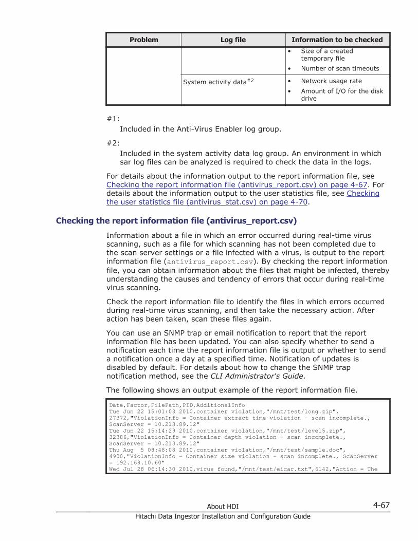
Problem Log file Information to be checked
• Size of a createdtemporary file
• Number of scan timeouts
System activity data#2 • Network usage rate
• Amount of I/O for the diskdrive
#1:Included in the Anti-Virus Enabler log group.
#2:Included in the system activity data log group. An environment in whichsar log files can be analyzed is required to check the data in the logs.
For details about the information output to the report information file, seeChecking the report information file (antivirus_report.csv) on page 4-67. Fordetails about the information output to the user statistics file, see Checkingthe user statistics file (antivirus_stat.csv) on page 4-70.
Checking the report information file (antivirus_report.csv)
Information about a file in which an error occurred during real-time virusscanning, such as a file for which scanning has not been completed due tothe scan server settings or a file infected with a virus, is output to the reportinformation file (antivirus_report.csv). By checking the report informationfile, you can obtain information about the files that might be infected, therebyunderstanding the causes and tendency of errors that occur during real-timevirus scanning.
Check the report information file to identify the files in which errors occurredduring real-time virus scanning, and then take the necessary action. Afteraction has been taken, scan these files again.
You can use an SNMP trap or email notification to report that the reportinformation file has been updated. You can also specify whether to send anotification each time the report information file is output or whether to senda notification once a day at a specified time. Notification of updates isdisabled by default. For details about how to change the SNMP trapnotification method, see the CLI Administrator's Guide.
The following shows an output example of the report information file.
Date,Factor,FilePath,PID,AdditionalInfoTue Jun 22 15:01:03 2010,container violation,"/mnt/test/long.zip",27372,"ViolationInfo = Container extract time violation - scan incomplete., ScanServer = 10.213.89.12"Tue Jun 22 15:14:29 2010,container violation,"/mnt/test/level5.zip",32386,"ViolationInfo = Container depth violation - scan incomplete., ScanServer = 10.213.89.12"Thu Aug 5 08:48:08 2010,container violation,"/mnt/test/sample.doc",4900,"ViolationInfo = Container size violation - scan incomplete., ScanServer = 192.168.10.60"Wed Jul 28 06:14:30 2010,virus found,"/mnt/test/eicar.txt",6142,"Action = The
About HDI 4-67Hitachi Data Ingestor Installation and Configuration Guide

infected file has been deleted."Wed Jul 28 07:59:21 2010,virus found,"/mnt/test/hydra.com",30971,"Action = The infected file has been repaired."Wed Jul 28 02:19:30 2010,server connect error,"/mnt/test/1M.txt",24483,""
The following table describes the information that is output to the reportinformation file.
Table 4-8 Information output to the report information file(antivirus_report.csv)
Item Description
Date The time that the file information was obtained, in MM DDhh :mm:ss format
Factor The cause of the real-time virus scanning error.
scan size exceededThe size of the scanned file exceeded the limit.
scan timeoutA scan timeout occurred.
Internal errorAn error occurred during internal processing.
server connect errorAn attempt to establish a connection with the scan server failed.
container violationThe container file could not be scanned due to the scan serversettings.
server too busyThe scan server could not perform a scan due to too many scanrequests.
Scan server errorAn error occurred on the scan server.
virus foundAn infected file was detected.
Suspected virusAn infected file was detected, or virus scanning terminatedabnormally.
FilePath The path to the file in which an error occurred during real-time virusscanning
PID The process ID of the CIFS client that accessed the file
AdditionalInfo Additional information.
FileSizeIf a scan timeout occurred, the size of the file for which scanningtimed out is output.
ScanServerIf a scan timeout occurred, if the container file could not bescanned, if the scan server could not perform operations, or if
4-68 About HDIHitachi Data Ingestor Installation and Configuration Guide

Item Description
an error occurred on the scan server, the IP address or hostname of the scan server is output.
ViolationInfoIf the container file could not be scanned, the cause is output.This cause depends on the scan policies set by using scansoftware.
ErrorInfoIf an error occurred on the scan server, the contents of the errorare output. For details about the output information, see Table4-9 Information output as additional information (ErrorInfo) inthe report information file when an error occurs on page 4-69.
ActionThe action taken for an infected file when detected. For detailsabout the output information, see Table 4-10 Information outputas additional information (Action) in the report information filewhen an infected file is detected on page 4-69.
Table 4-9 Information output as additional information (ErrorInfo) in thereport information file when an error occurs
Item Description
No scanning software isinstalled.
No virus scan software is installed on the scan server.
The scanning softwareservice has stopped.
The virus scan software service has stopped.
No information about theCIFS share access useris registered.
The user information for CIFS share access is notregistered on the scan server.
The information aboutthe CIFS share accessuser is incorrect.
The user information for CIFS share access that isregistered on the scan server is invalid.
An internal processingerror occurred on thescan server.
An internal error occurred on the scan server.
Table 4-10 Information output as additional information (Action) in thereport information file when an infected file is detected
Item Output when:
The infected file hasbeen repaired.
The infected file is repaired.
The infected file hasbeen rolled back.
The infected file is replaced with the version of the file(contained in a temporary file) existing before theinfection.
The infected file hasbeen deleted.
The infected file is deleted.
About HDI 4-69Hitachi Data Ingestor Installation and Configuration Guide

Item Output when:
A setting allowed accessto the file.
Access from the client to the infected file is permitted inaccordance with the scan conditions because the infectedfile cannot be repaired.
A setting denied accessto the file.
Access from the client to the infected file is rejected inaccordance with the scan conditions because the infectedfile cannot be repaired.
The file is a protectedfile and cannot berepaired.
The infected file cannot be repaired because the file is aWORM file, or because the file is a non-WORM file thatcannot be updated or deleted.
The file is a protectedfile and cannot berolled back.
The infected file is a WORM file and cannot be replacedwith the previously existing version of the file (containedin a temporary file).
The file is a protectedfile and cannot bedeleted.
The infected file cannot be deleted because the file is aWORM file within the retention period, or because the fileis a non-WORM file that cannot be updated or deleted.
No action taken. An infected file that cannot be repaired remains becausethe scan conditions do not permit any action to be taken.
Checking the user statistics file (antivirus_stat.csv)
Information such as the number of times real-time virus scanning isperformed and the scanning throughput is output to the user statistics file(antivirus_stat.csv). By checking the user statistics file, you canunderstand how real-time virus scanning is being used and obtain theinformation required for improving real-time virus scanning performance.
Because the user statistics file is output on a regular basis, the real-timevirus scanning performance might decrease. The user statistics file is notoutput by default. For details about how to specify the setting to output theuser statistics file, see the CLI Administrator's Guide.
The following shows an output example of the user statistics file.
StartTime,EndTime,PID,IPAddress,ScanCount,AvoidScanCount,CacheHit,Throughput,CreateBackupTime,CreateBackupSize,ConnectRetry,ScanTimeout,RequestOpen,RequestCloseThu Aug 19 09:21:17 2010,Thu Aug 19 09:25:20 2010,16776,10.213.77.238,0,16,0,0,0.000,0,0,0,16,0Thu Aug 19 09:26:15 2010,Thu Aug 19 10:23:04 2010,20868,10.213.77.238,0,35,0,0,0.000,0,0,0,32,3
The following table describes the information that is output to the userstatistics file.
Table 4-11 Information output to the user statistics file(antivirus_stat.csv)
Item Description
StartTime The time that the collection of information started, in MM DDhh:mm:ss format
4-70 About HDIHitachi Data Ingestor Installation and Configuration Guide
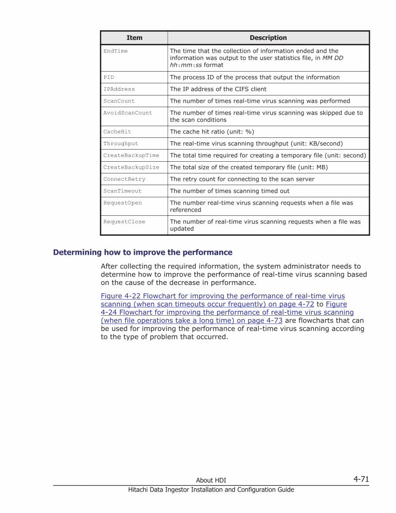
Item Description
EndTime The time that the collection of information ended and theinformation was output to the user statistics file, in MM DDhh:mm:ss format
PID The process ID of the process that output the information
IPAddress The IP address of the CIFS client
ScanCount The number of times real-time virus scanning was performed
AvoidScanCount The number of times real-time virus scanning was skipped due tothe scan conditions
CacheHit The cache hit ratio (unit: %)
Throughput The real-time virus scanning throughput (unit: KB/second)
CreateBackupTime The total time required for creating a temporary file (unit: second)
CreateBackupSize The total size of the created temporary file (unit: MB)
ConnectRetry The retry count for connecting to the scan server
ScanTimeout The number of times scanning timed out
RequestOpen The number real-time virus scanning requests when a file wasreferenced
RequestClose The number of real-time virus scanning requests when a file wasupdated
Determining how to improve the performance
After collecting the required information, the system administrator needs todetermine how to improve the performance of real-time virus scanning basedon the cause of the decrease in performance.
Figure 4-22 Flowchart for improving the performance of real-time virusscanning (when scan timeouts occur frequently) on page 4-72 to Figure4-24 Flowchart for improving the performance of real-time virus scanning(when file operations take a long time) on page 4-73 are flowcharts that canbe used for improving the performance of real-time virus scanning accordingto the type of problem that occurred.
About HDI 4-71Hitachi Data Ingestor Installation and Configuration Guide

Figure 4-22 Flowchart for improving the performance of real-time virusscanning (when scan timeouts occur frequently)
4-72 About HDIHitachi Data Ingestor Installation and Configuration Guide

Figure 4-23 Flowchart for improving the performance of real-time virusscanning (when connection errors occur frequently for scan servers)
Figure 4-24 Flowchart for improving the performance of real-time virusscanning (when file operations take a long time)
Keep the following in mind when attempting to improve the performance ofreal-time virus scanning:
When adding scan servers
About HDI 4-73Hitachi Data Ingestor Installation and Configuration Guide

If errors occur frequently because connections with scan servers cannotbe established, there might not be enough scan servers. In this case, addscan servers after reviewing the types and sizes of files that will bescanned, the number of clients that will concurrently access the HDIsystem, and the machine requirements for the scan servers.
When enhancing scan serversWhen connections for scan servers can be established without anyproblems and the network usage rate is far below the limit, theprocessing efficiency of the scan servers might be insufficient. In thiscase, enhance the scan servers to meet the operation needs of an HDIsystem. For the relation between the processing efficiency of scan serversand the time required for scanning viruses, contact your scan softwarevendor.
When enhancing the networkIf the network usage rate is near the limit and the scanning throughputhas decreased, a decrease in network performance is affecting theperformance of real-time virus scanning. In this case, enhance thenetwork to ensure that it can handle the traffic necessary for an HDIsystem.
If you add or enhance the scan servers or enhance the network, but theperformance does not improve, revise the scanning conditions. Revising thescanning conditions can reduce the load on the HDI system and improve real-time virus scanning performance. For details on revising the scanningconditions, see Revising the scanning conditions for the real-time virusscanning functionality on page 4-74.
Revising the scanning conditions for the real-time virus scanningfunctionality
The system administrator can revise the scanning conditions in the ScanConditions page of the Virus Scan Server Configuration dialog box toimprove the performance of real-time virus scanning. To do so, download thelog files from the List of RAS Information page (for Batch-download) ofthe Check for Errors dialog box and change the settings so that the real-time virus scanning functionality runs effectively.
Increasing the cache size
When you are using Symantec or McAfee virus scan software, you can reduceI/O load on the HDI system by efficiently using the cache that storesinformation about files determined to be free of viruses.
The system administrator must check the cache hit rate in the user statisticsfile and, if the cache hit rate is low, increase the cache size specified forCache size of scanning result. Note that an HDI system is able to cacheinformation for approximately 430 files with 1 MB.
4-74 About HDIHitachi Data Ingestor Installation and Configuration Guide

Increasing the scan timeout period
If scan timeouts occur frequently when network usage is low, increasing theperiod of time before a timeout occurs can reduce the timeout frequency. Thesystem administrator must check the log files for system activity data and, ifnetwork usage is low, increase the scan timeout periods specified forConnection time-out period and Scanning time-out period.
Reducing the number of times a virus scan is performed
In the default scanning conditions, Read and Write is the condition forperforming virus scanning. By setting Read only or Write only, you canreduce the number of times virus scanning is performed.
When Read only is set:Since virus scanning is performed when a file is being accessed, CIFSclients will not be infected.However, infected files might be stored in the storage system.
When Write only is set:Since virus scanning is performed when a file is being updated, infectedfiles will not be stored in the storage system.However, even when virus definition files are up to date, a virusundetectable during scanning might be sent to a CIFS client.
Suppressing the creation of temporary files
When you are using Symantec or McAfee virus scan software, temporary filesare created in the same folder as the files to be scanned, in case files areinfected or a virus scan error occurs during an update.
You must use the user statistics file to check the times at which temporaryfiles were created and the sizes of such files. You must also use the systeminformation log files to check the amount of disk drive I/O. If the I/O load onthe disk drive has increased due to the creation of temporary files, you canreduce the load by suppressing the creation of temporary files.
To suppress the creation of temporary files, specify scanning conditions asfollows:
When Read only is set for Scan timing:Temporary files are not created, regardless of the other settings.
When an item other than Read only is set for Scan timing:Temporary files are not created when the following items are specified:
¢ In Method of dealing with infected file, set Delete the file orAllow access.#
¢ When Specify is selected for Maximum size for scanning, selectthe Permit access to files that have exceeded the maximumsize check box.
¢ In Procedure if scanning fails, set Allow access.
About HDI 4-75Hitachi Data Ingestor Installation and Configuration Guide

#:When Delete the file is specified, any infected files that cannot berestored are deleted. Use backup data to restore the file.
Note that when the above settings are applied, files are not restored by usingtemporary files.
Selecting scan targets
When a CIFS share contains many files whose size exceeds several hundredsof megabytes (MB) or contains files in the gigabytes (GB), increased diskdrive I/O can reduce response performance throughout the entire HDIsystem. In addition, depending on the file type, virus scanning might not beeffective.
If problems like these occur, you can reduce the I/O load on the disk drive byselecting scan targets:
Exclude files that have a specific extension from the scan targetsContact to your scan software vendor to check the types of files for whichvirus scan is effective. On the Scan Conditions page of the Virus ScanServer Configuration dialog box, specify extensions to exclude from thescan targets.
Exclude specific files or paths in a CIFS share from the scan targetsIf you can identify the large files that cause a scan timeout from thereport information file, you can exclude these files and paths from thescan targets. For details on how to exclude specific files or paths in a CIFSshare from the scan targets, see the CLI Administrator's Guide.
Reducing the sizes of files to be scannedWhen you are using Symantec or McAfee virus scan software, you canexclude large files from scans by checking the size of the files that causedtimeouts from the report information file, and by changing the settings forthe size of files to be scanned. In Maximum file size of Maximum sizefor scanning, check the sizes of the files to be scanned.
Note that you must consider another method for scanning the files excludedfrom real-time virus scans. For example, virus scan software is installed onanother computer, and then the excluded files are periodically scanned forviruses on the computer.
About system settingsHDI systems provide functionality to recover the system settings saved onsystem LUs (a collective term for a cluster management LU and OS disks onboth nodes) in the event of failure.
OS diskA logical disk area where the OS on the node and programs that run onthe OS are stored. One OS disk is allocated per node.
4-76 About HDIHitachi Data Ingestor Installation and Configuration Guide

Cluster management LUAn LU, in the storage system, where settings such as those related to acluster configuration and file system are stored. One cluster managementLU is allocated per cluster.
In an HDI system, a batch operation can be used to save system LUs. Thesystem settings files that contain the information extracted from savedsystem LUs can also be saved to user LUs.
You can manually save system LUs and the system settings files, or can setthem to be automatically saved according to a specified schedule. To recoverthe system LUs if an error occurs, follow the instructions from maintenancepersonnel and upload the saved system settings file to the node.
Caution:
• You (the system administrator) must download the node settings file tostorage media outside the system after specifying the settings required tostart HDI system operations, such as defining a cluster configuration orcreating a file system.
• While the HDI system is in operation, make sure that you manuallydownload the node settings file whenever you change the configuration ofthe HDI system.
• If the settings file is not downloaded, the system LUs and storage systemmight not be recoverable if an error occurs.
• If the latest data for the node settings file is not saved, the system LUsmight not be recoverable if an error occurs.
• You cannot save the system configuration information when any of thefollowing conditions apply:- A failover occurred in the resource group.
- A cluster, node, or resource group is stopped or an error has occurredin the cluster, node, or resource group.
For system LUs, only one generation can be retained respectively per cluster.
The system administrator can specify any directory as the location for savingthe system settings file. In addition, the system settings file canautomatically be saved at specified intervals (periodic saving).
By default, the system settings information are periodically saved every dayat 00:07. Make sure that you set the time for periodic saving to a time periodduring which no jobs of the NDMP functionality are running. Do not executeany commands or perform any GUI operations when periodic saving of thesettings takes place.
About errorsIn the event of a failure in an HDI system, the system administrator mustobtain and review the error information from the management server and thenodes.
About HDI 4-77Hitachi Data Ingestor Installation and Configuration Guide
If you use SNMP error notifications, you can determine where the erroroccurred and identify its cause by using a trap issued to the predefined SNMPmanager.
If you use email error notifications, error warning emails are sent topredefined email addresses including the system administrator.
If the cause of the failure cannot be determined, the system administratormust send the log files to maintenance personnel for failure mode analysis.
Error information on the management serverHitachi Command Suite Common Component and the Hitachi File ServicesManager both write log files to the management server.
Hitachi Command Suite Common Component log files:
¢ Integrated trace log file
¢ Event log
Hitachi File Services Manager log file:
¢ Message log
The system administrator can change various log file settings, such as themaximum size or output level of the Hitachi File Services Manager trace log.
Node error information If an error occurs in an HDI system or a user performs an improperoperation, log files such as the system messages and system log data, alongwith the core file will be output.
You can use the File Services Manager GUI to view, download, or delete errorinformation on the nodes.
The system administrator can specify the number and size of log files to save,and the amount of time to save the core file.
Using SNMP to send error informationDepending on the error that occurs, a trap is issued to the predefined SNMPmanager to report the error information.
To use the SNMP error notification function, regularly obtain the MIBinformation of both nodes from the SNMP manager and make sure thatcommunication with the nodes is possible.
For details on how to check the data format of the error information reportedvia a trap and the system message, see the Administrator's Guide.
4-78 About HDIHitachi Data Ingestor Installation and Configuration Guide

Using the email error notification functionDepending on the type of error that occurs, an error warning email is sent topreset email addresses, including the system administrator, which are alldefined in the /enas/conf/email_alert.conf email alert file ahead of time.
For details about how to monitor a system by using email notifications, seethe Administrator's Guide.
About monitoring systems with SNMPBy using SNMP, you can acquire MIB object information and use thatinformation to monitor a system. (SNMP also allows you to send traps thatcontain error information.) The MIB objects provided by HDI for monitoringCPUs, memory devices, and networks are listed in the table below. For detailsabout other MIB objects, see the Administrator's Guide.
Table 4-12 MIB objects for CPUs
OID Object name Description
.1.3.6.1.4.1.2021.10.1.3 laLoad System load status
.1.3.6.1.4.1.2021.11.9 ssCpuUser Percentage of a CPU used byusers
.1.3.6.1.4.1.2021.11.10 ssCpuSystem Percentage of a CPU used by thesystem
.1.3.6.1.4.1.2021.11.11 ssCpuIdle Percentage of a CPU that is idle
.1.3.6.1.4.1.2021.11.50 ssCpuRawUser Amount of time users have beenusing a CPU
.1.3.6.1.4.1.2021.11.52 ssCpuRawSystem Amount of time the system hasbeen using a CPU
.1.3.6.1.4.1.2021.11.53 ssCpuRawIdle Amount of time a CPU has beenidle
.1.3.6.1.4.1.2021.11.54 ssCpuRawWait Amount of time a CPU has beenwaiting for I/Os
Table 4-13 MIB objects for memory devices
OID Object name Description
.1.3.6.1.4.1.2021.4.6 memAvailReal Amount of unused physical memory
.1.3.6.1.4.1.2021.4.14 memBuffer Amount of buffer cache (for device I/Os) in use
.1.3.6.1.4.1.2021.4.15 memCached Amount of page cache (for file I/Os) inuse
About HDI 4-79Hitachi Data Ingestor Installation and Configuration Guide
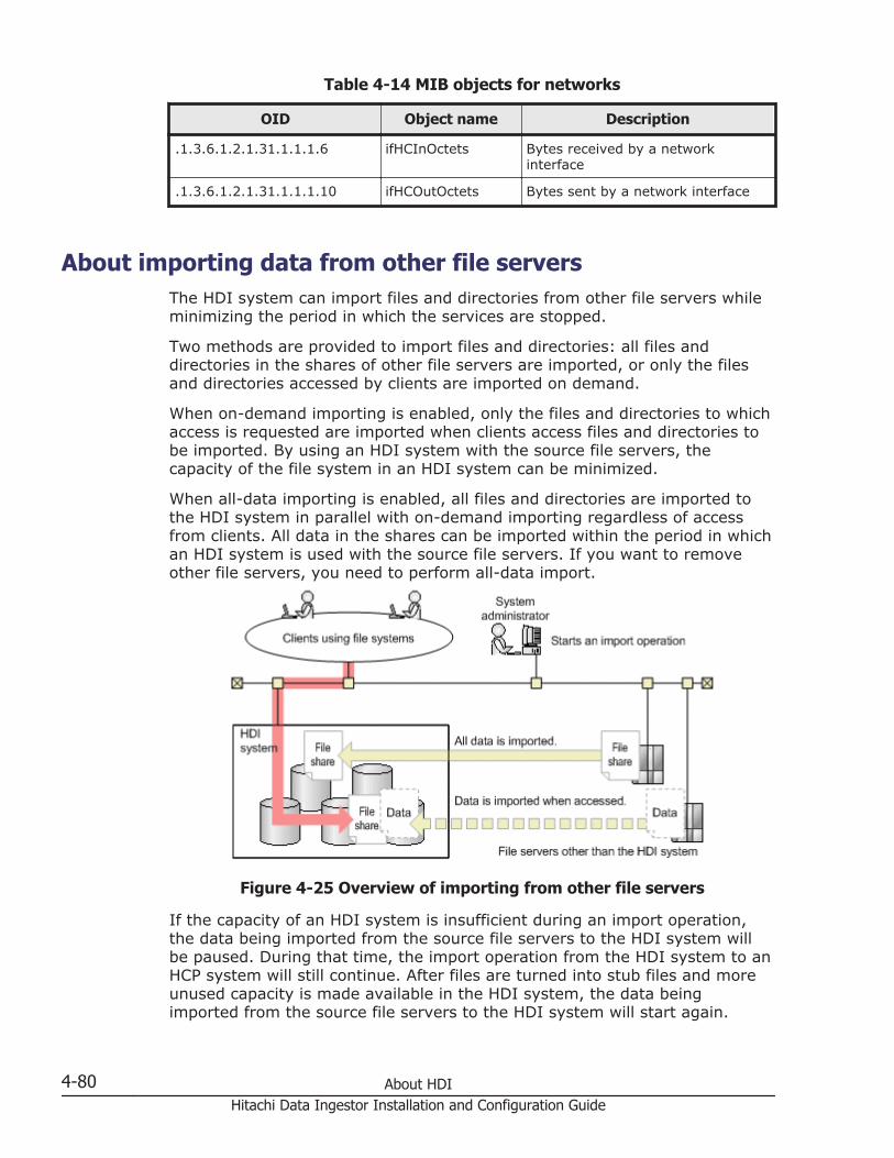
Table 4-14 MIB objects for networks
OID Object name Description
.1.3.6.1.2.1.31.1.1.1.6 ifHCInOctets Bytes received by a networkinterface
.1.3.6.1.2.1.31.1.1.1.10 ifHCOutOctets Bytes sent by a network interface
About importing data from other file serversThe HDI system can import files and directories from other file servers whileminimizing the period in which the services are stopped.
Two methods are provided to import files and directories: all files anddirectories in the shares of other file servers are imported, or only the filesand directories accessed by clients are imported on demand.
When on-demand importing is enabled, only the files and directories to whichaccess is requested are imported when clients access files and directories tobe imported. By using an HDI system with the source file servers, thecapacity of the file system in an HDI system can be minimized.
When all-data importing is enabled, all files and directories are imported tothe HDI system in parallel with on-demand importing regardless of accessfrom clients. All data in the shares can be imported within the period in whichan HDI system is used with the source file servers. If you want to removeother file servers, you need to perform all-data import.
Figure 4-25 Overview of importing from other file servers
If the capacity of an HDI system is insufficient during an import operation,the data being imported from the source file servers to the HDI system willbe paused. During that time, the import operation from the HDI system to anHCP system will still continue. After files are turned into stub files and moreunused capacity is made available in the HDI system, the data beingimported from the source file servers to the HDI system will start again.
4-80 About HDIHitachi Data Ingestor Installation and Configuration Guide

System configurations when data is imported from other file serversThe figure below shows an example system configuration when files anddirectories are imported from other file servers.
Figure 4-26 Example system configuration when data is imported fromother file servers
Both local authentication and domain authentication can be used for CIFSclient authentication. For external authentication servers, domain controllersand LDAP servers can be used.
The tasks required for system configuration are as follows:
• Connect the HDI system to the network that can access the source fileservers. You can connect multiple source file servers to an HDI node.
• When an LDAP server is used to authenticate users, register the useraccount associated with the data to be imported to the LDAP server aheadof time.
• If LDAP user mapping is used, the LDAP user mapping information set onthe import source must also be set in the HDI system.
• If the NFS protocol is used to import data, use the NFSv2 or NFSv3protocol.
The tasks required before importing that are related to the import-source fileserver are as follows:
• Stop client access to the import-source file server.
About HDI 4-81Hitachi Data Ingestor Installation and Configuration Guide

• Set the file shares of the import source to read-only. If a file-importoperation is started while writing is permitted, data might becomecorrupted.
Points to check before importing data from another file server
The file system specified as the import destination must meet thefollowing requirements:
• The file system is mounted with read and write permissions granted.
• The file system does not use the WORM functionality.
• Single instancing is not enabled.
• The file system shares no HCP data migrated from other HDI systems.
• The file system is the Advanced ACL type (when the CIFS protocol is usedto import data).
• The file system is not using share-level security.
A maximum of 10 KB per file is required in the management area on thetarget file system. Take this into account when considering the file systemcapacity.
Check the following points related to operation of the import-destination file system:
• If you want to set subtree quotas for the import-target directories, specifythe settings so that only the files and directories accessed by clients areimported on demand for the share that is the highest in the hierarchy,and then start the import operation. After that, set subtree quotas. Aftersetting the quotas, change the import method so that all files anddirectories are imported.
• When the Backup Restore functionality is used for the target file system,files cannot be accessed unless they have been imported by the time theBackup Restore functionality acquires a backup.
Check the following points related to importing data:
• When a directory that has not yet been imported is accessed for the firsttime, the data is imported from the import-source file server on demand.If the number of files or directories in the directory is large, importing thedata takes a long time. As a result, Explorer or other applications used onthe client side might timeout. However, because the import processingwill still continue even if a timeout occurs, wait a while until theprocessing completes, and then access the target directory again.
• For file systems that are importing data, if you perform operations thatrecursively scan the directory (for example, searching all files, displayingthe properties of Explorer, or using the Show pop-up description forfolder and desktop items function to display pop-ups), the processingtakes a long time because data is imported for a large number ofdirectories on demand. Therefore, do not perform operations that
4-82 About HDIHitachi Data Ingestor Installation and Configuration Guide

recursively scan the directory. Note that you can disable the Show pop-up description for folder and desktop items function by using theFolder Options dialog box of Explorer.
• If you delete or change the name of a file or directory that was importedto immediately under the import-target directory, and then an all-dataimport is performed, the file or directory is imported again.
• When on-demand imports (for which files and directories are onlyimported when they are accessed by clients) are enabled, some datamight not be imported into the HDI system. When removing source fileservers, change the settings in advance so that all files and directories areimported by using the datamigratestart command for clusterconfigurations or by using the GUI or the datamigratestart commandfor single-node configurations.
• If the first character of a file or directory name is a period (.), thehidden-file attribute is applied to the import target.
• If the settings are configured so that only the data accessed by clients isimported, all files in the target file system are managed as files that havethe offline attribute. For details about the offline attribute, see the FileSystem Protocols (CIFS/NFS) Administrator's Guide.
• When migrating the target-file-system data to the HCP system duringimport processing, the offline attribute is set for the files that have notbeen migrated to the HCP system. For details about the offline attribute,see the File System Protocols (CIFS/NFS) Administrator's Guide.
If you are using the CIFS protocol to import data, check the following points:
¢ If source file servers are in a Windows environment, you might not beable to access imported files due to the differences in the ACLspecifications between Windows and the HDI system. For details onthe differences in specifications when user resources are migratedfrom a Windows environment, see the File System Protocols (CIFS/NFS) Administrator's Guide.
¢ Specify the shared directory at the highest level as the source CIFSshares. Other CIFS shares under the CIFS shares specified in theimport source are imported at the same time.
¢ Disable access based enumeration for the import-source CIFS share.If access based enumeration is enabled for the import-source CIFSshare, files without access permissions cannot be detected.
¢ If a directory in an import-source share is mapped to a client networkdrive and access from the client is stopped, ask the client todisconnect the network drive. When starting access from a client, askthe client to map the directory in the import-target share to a networkdrive.
¢ When shortcuts are imported, the link destinations of the shortcutsmust be changed as necessary. If a client specifies the host name orIP address of an import-source file server as a link destination, askthe client to change the host name or IP address to the host name orIP address of the target node.
About HDI 4-83Hitachi Data Ingestor Installation and Configuration Guide

¢ Even if real-time scanning is set to be performed when CIFS clientsupdate a file, we recommend that you perform virus scans for the filesto be imported. For all-data imports, real-time scanning is notperformed for the files that are being imported.If CIFS clients access files before the import operation is completed, itmight take a long time to scan files. If clients access large files, whichcan cause scans to timeout, consider reducing the maximum size offiles to be scanned, or allowing access to the files for which scanningfailed. Note that scan timeouts do not affect import operations.
¢ To import data by using domain authentication, the CIFS serviceneeds to be running. If the CIFS service stops while the data is beingimported, the import process might result in an error. In such a case,start the CIFS service, and then import the data again.
If you are using the NFS protocol to import data, check the following points:
¢ Hard link information is also imported. Imported hard links that aremigrated to the HCP system are migrated as one file.
¢ If hard links exist under an import-source share directory and youwant to set a subtree quota under the corresponding import-targetshare directory, set the subtree quota so that all the hard links areimported under the same subtree quota directory. Hard links are notimported if different subtree quotas are set.
If you are migrating the data of the import-destination file systemto an HCP system, check the following points:
• Importing of all data stops temporarily, and importing of only the dataaccessed by HDI from the client takes place if migration occurs duringimport or if the remaining file system capacity of the import-target falls toor below the threshold specified by the datamigratelimitset command(the initial threshold is 10 percent). After migration to HCP finishes, stubprocessing of files starts and continues until the remaining file systemcapacity of the import-target reaches or exceeds the threshold forresuming the stopped import of all data (the initial threshold is 20percent). The stub processing is based on the setting by thedatamigratelimitset command regardless of the stub processingthreshold specified by the arcreplimitset command. Ensure that the filesystem capacity of the import-target is sufficiently larger than the import-source.
• Specify migration policies after all file and directories are imported, orconfigure the settings so that a migration is performed on a regular basisduring import processing so as not to affect the migration processingtime. Note that, if a migration is performed during import processing, theprocessing to import all the files and directories temporarily stops but theprocessing to import the files and directories accessed by the HDI systemclient is performed. After the migration finishes, the processing to importall the files and directories resumes.
• When data that has just been imported is then immediately migrated,files for referencing the data on the import-source server are created in
4-84 About HDIHitachi Data Ingestor Installation and Configuration Guide

the .history directory. These files cannot be referenced if importdefinition information (which is created when data is imported fromanother file server) is deleted. If this happens, reference the files createdin the .history directory after the migration to the HCP system iscompleted.
• After all files and directories are imported, immediately delete importdefinition information. If you do not delete import definition information,the processing required to restore data from the HCP system or referencethe .history directory takes time, because the number ofcommunications increases.
About clients using file systemsThis section describes what the system administrator needs to know beforeclients start using file systems.
Notes on using a file system from an NFS clientNote the following points when you change the settings in the HDI system,you want to use a file system from an NFS client:
• To recreate an HDI system file system mounted from an NFS client, firstuse the NFS client to unmount the file system, and then after the filesystem has been recreated, mount it.
• If you delete an NFS share for the HDI system file system mounted froman NFS client, it might not be possible to unmount that file systemdepending on the implementation of the NFS client. If you cannotunmount the file system, restart the NFS client to release the file systemfrom the mount state.
• Even if you change the attribute of the NFS mount point of the file systemto which you mount from an NFS client, the result of the change mightnot be able to be checked from the NFS client side. In such cases, mountthe file system again from an NFS client.
• The NFS client host's administrator must unmount the HDI file systemfrom the NFS client before the HDI system administrator changes themaximum buffer size for the NFS shares. Remount the HDI file systemonly after the change has been checked.
If a file system is used from an NFS client, there are several things to note inthe situations below. For details, see the File System Protocols (CIFS/NFS)Administrator's Guide.
• When mounting a file system from an NFS client
• When locking a file from an NFS client
• When operating a file system from an NFS client
About HDI 4-85Hitachi Data Ingestor Installation and Configuration Guide
Notes on using a file system from a CIFS clientFor notes on using a file system from a CIFS client, see the File SystemProtocols (CIFS/NFS) Administrator's Guide.
Operations on CIFS clients that were using resource group services migratedby a failover or failback are forcibly suspended.
Note on using a file system from an FTP clientThe following are notes on using a file system from an FTP client.
• To perform an operation from an FTP client for a file or directory whosename contains non-ASCII characters, you need to specify a character-encoding scheme for the operating environment on the client thatproperly displays all of the characters.
• If a failover or failback occurs while an FTP client is accessing a filesystem that belongs to the target resource group, the connection will beforcibly disconnected or placed in the response-wait status. To restartaccess to the file system, reconnect to the file system.
• When using the FTP service, an anonymous user cannot upload a file if thefile name contains non-ASCII characters.
• If the name of a file or directory in the HDI system is ~ftp-user-name,and that file or directory is specified for the ftp command, make sure tospecify the file or directory name either with an absolute path or with arelative path starting from a higher level before executing the commandfrom an FTP client.If the ftp command is executed with only a file or directory name of theformat ~character-string (and without an absolute path or without arelative path starting from a higher level), the following occurs:
¢ If character-string is a user name registered in an HDI system:If the home directory of the specified user is under the FTP logindirectory, the home directory of the specified user or a file with thesame name as the home directory becomes the processing target.If the home directory of the specified user does not appear under theFTP login directory, an error occurs.
¢ If character-string is not a user name registered in an HDI system:~character-string becomes the processing target.
• If the ftp command is executed from an FTP client and with only a tilde(~) specified for the directory or file name, the FTP login directorybecomes the processing target.
• The SFTP service supports SSH2 only.
• For the SFTP service, make sure that the maximum number of clients thatcan log in simultaneously is 500. If over 500 clients log in simultaneously,the system becomes unstable.
4-86 About HDIHitachi Data Ingestor Installation and Configuration Guide
5Backup Operations in an HDI System
This chapter describes what system administrators must understand and takeinto consideration before performing backup operations in an HDI system.
□ Overview of the backup functionality
□ Using the NDMP functionality
Backup Operations in an HDI System 5-1Hitachi Data Ingestor Installation and Configuration Guide

Overview of the backup functionalityYou can use the NDMP (Network Data Management Protocol) functionalityprovided by Backup Restore, to work together with backup managementsoftware (that supports the NDMP functionality) to save file system data to atape device on the network. This functionality can be used for file systemsthat share no HCP data migrated from other HDI systems.
If the NDMP functionality is used while applications are using data, considerthe integrity of the data that is being used and the data to be backed up orrestored.
Using the NDMP functionalityThis section contains information for the system administrator to be aware ofbefore using the NDMP functionality.
Overview of the NDMP functionalityIn conjunction with backup management software, the NDMP functionalitycan copy file system data to backup media, and also restore backed up datastored on media to a file system.
Because this functionality is designed to copy data to backup media not in astorage system, you will be able to recover file system data from the copieddata even if the hardware in a storage system fails.
The figure below illustrates the NDMP functionality.
Figure 5-1 Overview of the NDMP functionality
The NDMP functionality supports the following tape devices:
5-2 Backup Operations in an HDI SystemHitachi Data Ingestor Installation and Configuration Guide

• A tape device connected to the media server
• A tape device connected to a node via a SAN#
#:This functionality can only be used in cluster configurations.
We recommend that you stop file system operations before performing abackup, but you can also perform a backup for an active file system. In thismanual, a backup performed by using the NDMP functionality is called anoffline backup.
If an offline backup is performed without stopping file system operations,offline backup processing will continue even if a file is modified or deletedduring the offline backup because the accuracy check of the offline backup isnot enhanced by default. By changing the conditions for interrupting anoffline backup by using the ndmpfsconfig command, you can enhance theaccuracy check of the offline backup. The differences in offline backupprocessing operations when the offline backup accuracy check is enhancedand when it is not enhanced are shown below.
• When the accuracy check of an offline backup is not enhanced (default)Offline backup processing ends successfully even if a file is modified ordeleted during an offline backup. However, the integrity of the backed upfiles is not guaranteed.You can use this setting when you do not want to interrupt offline backupprocessing even if the offline backup performed at night does not end bythe time the workday operations start.
• When the accuracy check of an offline backup is enhancedOffline backup processing ends with an error if a file is modified or deletedduring an offline backup.
Estimating the capacity of the backup mediaYou must prepare backup media that can store quota information, inodeinformation, and ACL information, in addition to the directories and files to bebacked up. If the capacity of the backup media is insufficient, the backupoperation fails and an error occurs. Use the estimated value calculated by thefollowing formula as a guideline, and then prepare a tape device that hassufficient capacity.
When a migration is performed that links to the HCP system, only files thatare excluded as migration targets and files that have not been updated sincea migration are backed up to media. Therefore, when you consider thecapacity of the backup media, subtract the capacity of files that are notbacked up to media (files that have not been updated since migration) fromthe capacity estimated by the formula below. For example, if the percentageof files that are not backed up to the total capacity is 60%, prepare backupmedia with 40% of the estimated capacity as a rough indication.
If a file system for which single instancing is enabled is backed up, the data isstored in a backup media with its capacity reduced. In this case, preparebackup media by using the disk volume used for a backup-target volume as a
Backup Operations in an HDI System 5-3Hitachi Data Ingestor Installation and Configuration Guide
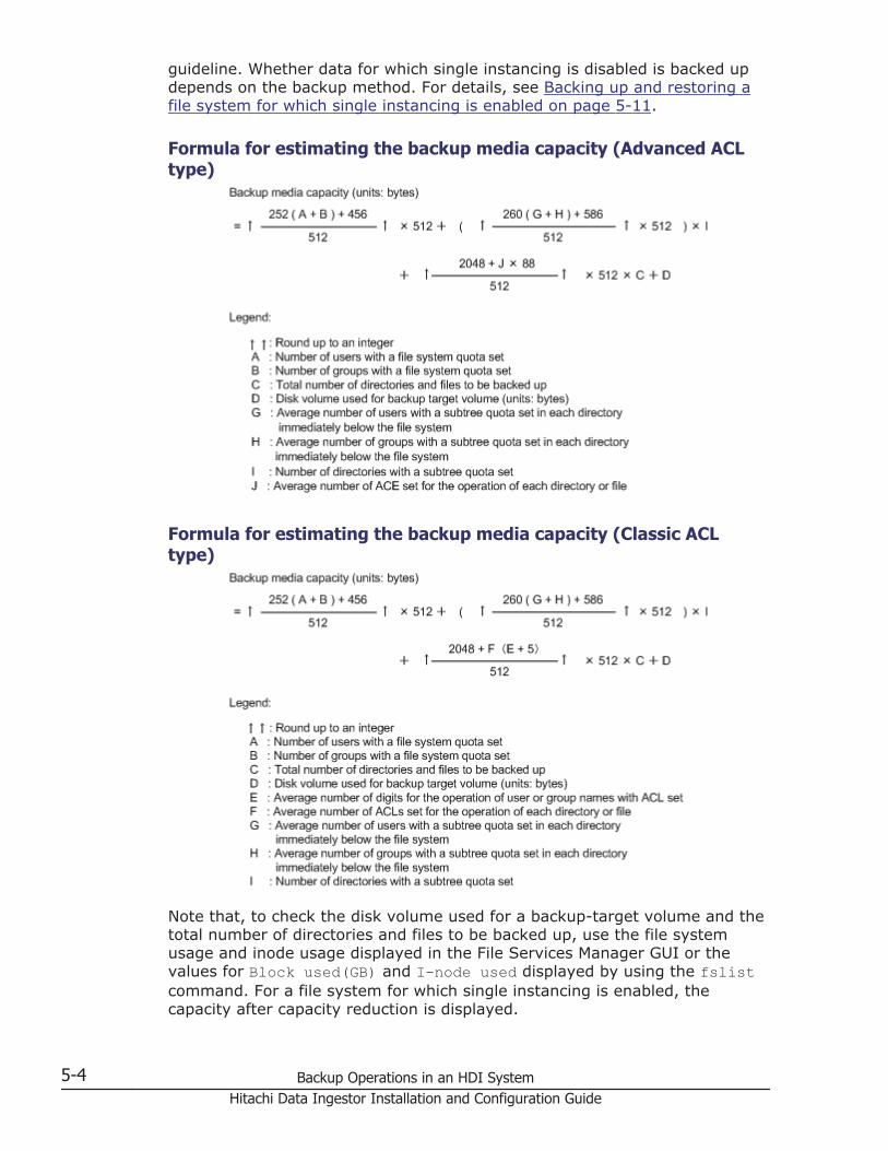
guideline. Whether data for which single instancing is disabled is backed updepends on the backup method. For details, see Backing up and restoring afile system for which single instancing is enabled on page 5-11.
Formula for estimating the backup media capacity (Advanced ACLtype)
Formula for estimating the backup media capacity (Classic ACLtype)
Note that, to check the disk volume used for a backup-target volume and thetotal number of directories and files to be backed up, use the file systemusage and inode usage displayed in the File Services Manager GUI or thevalues for Block used(GB) and I-node used displayed by using the fslistcommand. For a file system for which single instancing is enabled, thecapacity after capacity reduction is displayed.
5-4 Backup Operations in an HDI SystemHitachi Data Ingestor Installation and Configuration Guide

Data to be backed up or restoredThe NDMP functionality backs up the following types of data to media:
• File system information (quota information and WORM function settings)
• Directory and file information (inode, ACL information, and file attributes)
• Directories and filesSometimes a directory or file whose path contains one or more linefeedcodes is not backed up. To ensure that the directory or file is backed up,we recommend editing the path and removing the linefeed codes.
Reference note:For details on directory and file attributes to be backed up, seeAttributes to be backed up on page E-2.
The NDMP functionality allows data backed up to media to be restored to anode that is in the same cluster as the backup target. Data can only berestored within the cluster where the backup target node is located.
Recommended time to perform backup and restore operationTo minimize impact on user operations due to service stopping anddegradation of response time, we recommend that you perform backup andrestore operations when the entire system has a light load.
When performing a backup or restore operation while the client frequentlyaccesses the volume in the storage system (such as file systems), it mighttake some time before the processing completes.
Performing an incremental backupThe incremental backup method backs up data that has been changed sincethe previous backup.
There are two types of incremental backup, which are as follows:
Differential-data backupA differential-data backup backs up all data that has been changed sincethe previous full backup.
Incremental-data backupAn incremental-data backup backs up data that has been changed sincethe previous full backup, differential-data backup, or incremental-databackup.
When performing an incremental backup, keep the following points in mind:
• Even if you perform the following operations on directories and files thathave not been changed since the previous backup, an incremental backupwill not back up those directory and files.
¢ Changing a path (moving directories and files)
¢ Changing a name
Backup Operations in an HDI System 5-5Hitachi Data Ingestor Installation and Configuration Guide

¢ DeletingWe recommend that you perform a full backup when the file systemconfiguration has been changed without change to the directories andfiles. If you do not perform a full backup, you might not be able torecover data from just before the time that an error occurred.
• If a file system or directory in which quota information has been set isspecified as a backup source, an incremental backup backs up all quotainformation.
• Backup Restore manages the incremental backup history information foreach file system.For example, assume an offline backup was performed at 06:00 for thefile system filesystem01, in which a file system is specified as thebackup source.In this case, history information will be recorded as illustrated in thefollowing figure.
Figure 5-2 Backup history informationHistory information for filesystem01 is recorded as an offline backupperformed at 06:00.
• For one file system, we recommend that an incremental backup beperformed with one NDMP policy. The following shows an example of anincremental-data backup performed with one NDMP policy.
5-6 Backup Operations in an HDI SystemHitachi Data Ingestor Installation and Configuration Guide

Figure 5-3 Incremental-data backup performed with one NDMPpolicy
When performing an incremental-data backup with one NDMP policy, thedifferential data from the previous full backup or incremental-databackup, acquired with the same policy, is backed up. An incremental-databackup at 06:00 will back up the differential data for the period after00:00. Similarly, an incremental-data backup at 12:00 will back up thedifferential data for the period after 06:00.
About access control for the NDMP serverRegistering the IP addresses and host names of backup servers in the /etc/hosts file enables you to restrict the clients that can access the NDMP serverto only those backup servers registered in the /etc/hosts file. Note that ifyou do not register any information about backup servers in the /etc/hostsfile, any client can access the NDMP server. When a client other than abackup server registered in the /etc/hosts file attempts to access the NDMPserver, the KAQB14211-W and KAQB14213-W messages are output to theNDMP server log (/enas/log/ndmpserver.log).
To prevent unauthorized accesses, you can register information about backupservers in the /etc/hosts file in the following format, depending on how theHDI system will be used.IP-address host-name backup-server-name [host-name-alias ...]Backup server names must begin with BackupServer. Backup server namescan only contain alphanumeric characters and underscores (_). A maximumof 256 information items of backup servers can be registered in the /etc/hosts file. If 257 or more items are registered, items from 257 onward areinvalid.
Backup Operations in an HDI System 5-7Hitachi Data Ingestor Installation and Configuration Guide

The following is an example of adding information items in the /etc/hostsfile.
## BACKUP SERVER ADDRESS#10.208.151.19 back-1 BackupServer0110.208.151.197 back-2 BackupServer02
The information registered in the /etc/hosts file is applied to both nodes inthe cluster.
Also, after editing the /etc/hosts file, you need to restart the NDMP serverson both of the nodes in the cluster. For details on how to restart an NDMPserver, see the CLI Administrator's Guide.
Communication path used for backup or restore operationsThe communication path between the NDMP server and media server, andthe communication path between the NDMP server and backup server aredetermined based on the routing information set in File Services Manager.Therefore, depending on the set information, communication between theNDMP server and media server, and communication between the NDMPserver and backup server might use different ports or paths during backup orrestoration.
Operations that cannot be executed during backup or restorationIf you execute the ndmpcontrol command, or if the NDMP server isautomatically restarted by executing the ndmpconfig, tapeadd, or tapedelcommand, the backup or restore operation being performed on the nodewhere you executed the command might terminate with an error.
In addition, when processing is being performed for a backup or restoreoperation that is using a tape device connected to a node via a SAN, do notperform any of the following operations:
• Executing the tapeadd command on a node#
• Executing the tapelist command in which the -A, -D, or -d option isspecified on a node#
• Using the backup management software to perform GUI operations orexecute commands that manage tape devices.
#:If any of these commands are executed on a node on which a backupor restore operation is not being performed, a backup or restoreoperation being performed on the other node might terminate with anerror.
5-8 Backup Operations in an HDI SystemHitachi Data Ingestor Installation and Configuration Guide

Notes on operations using File Services ManagerDo not perform any of the following File Services Manager operations and aBackup Restore operation at the same time:
• Starting or stopping a cluster
• Performing a forced stop for a cluster
• Changing a cluster configuration
• Starting or stopping a node
• Performing a forced stop for a node
• Starting or stopping a resource group
• Performing a forced stop for a resource group
• Disabling or restarting resource group monitoring
• Changing the execution node of a resource group
• Unmounting the target file system
Doing so might cause the File Services Manager operation or the BackupRestore operation to terminate with an error.
Precautions on starting the OS on a nodeWhen a tape device is connected to nodes via a SAN, the tape device isshared among the nodes. If the OS on one of the nodes is started orrestarted, a backup or a restoration being performed on the other node mightterminate with an error. When performing a backup or a restoration, makesure that the OS on the other node that shares the tape device is not beingstarted or restarted.
Limitations on the functionality of the backup management softwareThe NDMP functionality does not support some functionalities provided bybackup management software. The following table shows the functionalities(provided by backup management software) that are available to the NDMPfunctionality.
Table 5-1 Backup management software functionalities and whether theyare supported by the NDMP functionality
Functionality Supported
Backup execution Manual Yes
Automatic (scheduled) Yes
Backup type Full backup Yes
Cumulative incremental Yes#1
Differential incremental Yes#1
Backup and restoreby#2
Volume Yes
Backup Operations in an HDI System 5-9Hitachi Data Ingestor Installation and Configuration Guide

Functionality Supported
Directory Yes
File Yes
Path-based history#3 Yes
Direct Access Recovery (DAR) Yes
Restore destination The node that has the volume to bebacked up
Yes
The node for the failover destination Yes
Redirected Restore to a differentclient (a node in another cluster)
--
Legend: Yes = Supported. -- = Not supported.
Note:Depending on the backup management software used, different functionsare available. For details about which the functions are available withwhich backup management software, see the correspondingdocumentation.
#1:In an HDI system, the incremental backup only backs up the directoriesand files whose contents are modified.
#2:The maximum length of the path for the directory or file, to be specifiedfor a backup or restore operation, varies depending on which backupmanagement software is used. For details, see the supplementary BackupRestore documentation that is provided with HDI.
#3:Path-based history is a functionality used for sending file historyinformation from an NDMP server to backup management software duringa backup operation. This file history information consists of path namesfor backed-up directories and files.Depending on the file history information, you can restore in eitherdirectory or file units.
Notes on backing up and restoring WORM file systemsThis subsection describes the precautions to take when backing up orrestoring a WORM file system.
Notes on backing up a WORM file system
If the autocommit functionality is enabled for a WORM file system, files thathave not been accessed by clients since their autocommit intervals haveelapsed are not yet WORM files. Any such files are backed up as WORM files.
5-10 Backup Operations in an HDI SystemHitachi Data Ingestor Installation and Configuration Guide
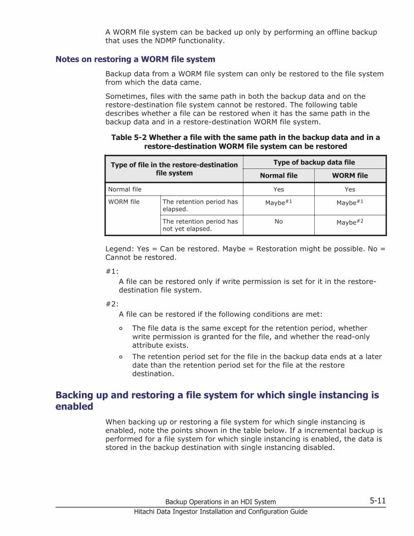
A WORM file system can be backed up only by performing an offline backupthat uses the NDMP functionality.
Notes on restoring a WORM file system
Backup data from a WORM file system can only be restored to the file systemfrom which the data came.
Sometimes, files with the same path in both the backup data and on therestore-destination file system cannot be restored. The following tabledescribes whether a file can be restored when it has the same path in thebackup data and in a restore-destination WORM file system.
Table 5-2 Whether a file with the same path in the backup data and in arestore-destination WORM file system can be restored
Type of file in the restore-destinationfile system
Type of backup data file
Normal file WORM file
Normal file Yes Yes
WORM file The retention period haselapsed.
Maybe#1 Maybe#1
The retention period hasnot yet elapsed.
No Maybe#2
Legend: Yes = Can be restored. Maybe = Restoration might be possible. No =Cannot be restored.
#1:A file can be restored only if write permission is set for it in the restore-destination file system.
#2:A file can be restored if the following conditions are met:
¢ The file data is the same except for the retention period, whetherwrite permission is granted for the file, and whether the read-onlyattribute exists.
¢ The retention period set for the file in the backup data ends at a laterdate than the retention period set for the file at the restoredestination.
Backing up and restoring a file system for which single instancing isenabled
When backing up or restoring a file system for which single instancing isenabled, note the points shown in the table below. If a incremental backup isperformed for a file system for which single instancing is enabled, the data isstored in the backup destination with single instancing disabled.
Backup Operations in an HDI System 5-11Hitachi Data Ingestor Installation and Configuration Guide

Table 5-3 Notes on backing up or restoring a file system for which singleinstancing is enabled
Notes Operation when the notes are notfollowed
When backing up a file system for whichsingle instancing is enabled, you need toadjust the schedule so that single-instancing tasks are not executed duringthe backup.
If single-instancing tasks are executedduring backup processing, the backed updata might be invalid and a restorationmight fail.
Stop the NFS, CIFS, FTP, SFTP, and TFTPservices when performing a backupbecause the same problem occurs if thereis access from a client during the backup.
Adjust the schedule by taking into accountthe time required for each processing taskand then specify the appropriate settingsfor the date and time for executing abackup, and the date and time for startingand stopping single-instancing tasks (thevalue of Maximum duration specified inthe 5. Schedule page of the SingleInstancing Wizard).
When backing up the data in a file systemfor which single instancing is enabled,specify the mount point for the file systemas the base point of a backup target.
If a backup is performed by specifying adirectory under the mount point as thebase point of a backup target, backupprocessing might fail due to a capacityshortage at the backup destination becausethe data is stored in the backup media withsingle instancing disabled.
When restoring the data in a file system forwhich single instancing is enabled, set therestore destination immediately below themount point of a new file system.
If the data is restored to the backup sourcefile system, the restore processing mightfail or it might take a long time for theprocessing to finish.
If the data is restored to a subdirectory,the restore processing might fail or therestored data might be invalid.
When restoring the data in file systems forwhich single instancing is enabled, performa restoration for each file system.
If a restoration is performed for each file ordirectory, the restore processing might failor the restored data might be invalid.
When restoring the data in a file system forwhich single instancing is enabled, therestore destination file system must also beset up so that single instancing is enabled.
Restore processing fails.
5-12 Backup Operations in an HDI SystemHitachi Data Ingestor Installation and Configuration Guide

6Linking HDI and HCP
This chapter explains what system administrators must understand orconsider before using HDI systems linking with an HCP system as a combinedsystem.
□ Functionalities for managing migration
□ What must be checked before linking an HDI system with an HCP system
Linking HDI and HCP 6-1Hitachi Data Ingestor Installation and Configuration Guide

Functionalities for managing migrationBy linking an HDI system to an HCP system, you can migrate HDI data to anHCP namespace according to the policies set by the system administrator.The system administrator sets policies that define the migration conditions foreach file system. The set policy is executed according to the schedulespecified as a migration task. In addition, the data migrated to the HCPsystem can be shared with other HDI systems.
This section describes functionality for managing migration from an HDIsystem to an HCP system.
Correspondence between file systems and namespacesOne tenant in the HCP system must be assigned to only one HDI system. Youcan assign one tenant in the HCP system to multiple HDI systems. Anamespace is allocated at the migration destination for each HDI file systemor file share created in a directory directly under the file system. HCP linkageand namespace assignment are specified for each file system. When sharingdata that has been migrated to an HCP system with other HDI systems, asingle namespace becomes associated with multiple file systems or file sharesbecause multiple HDI systems are able to access the namespace at themigration destination.
The following figure shows the correspondence between HDI file systems andmigration-destination namespaces.
6-2 Linking HDI and HCPHitachi Data Ingestor Installation and Configuration Guide

Figure 6-1 Correspondence between file systems, tenants, andnamespaces
Changing files to stub filesWhenever a migration task's date and time is reached, files in a file systemare migrated to an HCP system according to the corresponding migrationpolicy.
If a migrated file is turned into a stub file, only the attribute information ofthe file will remain. HDI periodically (at times when a migration task is notscheduled) turns files into stub files. At the time of the conversion, if theremaining file system capacity is less than the threshold (initial value: 10%),
Linking HDI and HCP 6-3Hitachi Data Ingestor Installation and Configuration Guide

the system turns files into stub files in order from the least recently accesseduntil the remaining capacity rises above the threshold.
If the replication functionality is not enabled for the HCP system, use thearcreplimitset command to set the threshold file system capacity at whichthe HDI system turns files into stub files to 0 GB (to disable the stub filefunctionality). If the stub file functionality is enabled and a failure occurs onboth the HCP system and the HDI system, the data for stub files might not berestored.
The following figure shows the process of a file being turned into a stub file.
Figure 6-2 Turning a file into a stub file
Internal processing before and after transferring dataTo shorten the execution time when a large number of files are migrated,before or after data is transferred to an HCP system, the internal processingthat creates a list of the target files occurs. Note that, in the post-processing,a list of the files that failed to migrate will be created for the next migration.
A list of the target files is created based on event information such as theupdating, creating, or renaming of files and directories. The processing timesfor transferring data to HCP systems differ depending on the amount of dataof the target files and on the network environment. However, the processingtimes for creating lists of the target files differ depending on the number ofevents.
The status of the pre- or post-processing might not be synchronized with thetask status displayed in the GUI. For example, if you stop the migration taskwhile the pre-processing is being executed, the pre-processing does not stopuntil the processing for creating the list of the target files is complete. Inaddition, the post-processing is executed in the background, so the GUIdisplays the status that indicates that the task is complete.
The following table shows the processing status of migration tasks, the statusto be displayed in the GUI, and the factors that affect the processing time.
6-4 Linking HDI and HCPHitachi Data Ingestor Installation and Configuration Guide

Table 6-1 The processing status of tasks, the status to be displayed in theGUI, and the factors that affect the processing time
Processingstatus of
tasks
Information to be displayed in the Task Listpages of the Task Management dialog box
Factors thataffect theprocessing
timePresent status Progress
Not executed Standby orScheduled
-/- (-) None
Pre-processing Running calculating The number ofevents
Transferringdata
number-of-processed-files-and-directories/total-number-of-files-and-directories(progress%)
The amount ofdata of thetarget files andthe networkenvironmentBacking up
quotainformation
post-command executing
Post-processing Standby orScheduled
-/- (-) Number ofevents
If a migration task is performed during pre- or post-processing, theKAQM37142-E message is output and the task fails. Use the arctaskstatuscommand to check the progress of the pre- or post-processing. If the pre- orpost-processing takes a long time, make the maximum duration longer whenyou set the task schedule, or use the arcmodectl command to specify thesettings so that the initial mode is used when executing a task.
When data is transferred, all files are migrated before directories aremigrated. Before a directory is migrated, it is prepared for migration.Progress is not updated while directories are being prepared for migration.The larger the number of directories to be migrated, the longer it takes forpreparation to finish.
Recalling files to an HDI systemWhen a stub file is accessed from an HDI client, the file can be viewed oredited because the data migrated to an HCP system is written in the stub file.
The process in which the data migrated to an HCP system is written to a stubfile on an HDI system is called recall.
The first time a stub file is accessed, the stub file is recalled. In addition tothe time needed to access the file, time is needed to recall the file.
It is possible to keep file data in an HDI system (for example, stop files frombeing turned into stub files). This practice is called cache residency, andprevents access performance from decreasing. By setting conditions so thatfiles are not turned into stub files, the processing time associated withrecalling files that meet the conditions decreases, and access performance isbetter than that of stub files.
Linking HDI and HCP 6-5Hitachi Data Ingestor Installation and Configuration Guide

If a recall fails because of a failure on the primary HCP system, the HCPreplication function can be used to automatically switch the system to thereplica HCP system by setting the replica system information in the HDIsystem, allowing you to continue recall processing.
Figure 6-3 Continued recall processing by the replica HCP system
Restoring files by using version managementGenerations of the data migrated to an HCP system are managed for eachdate and time when migration was performed by using version management(versioning). In HDI systems, you can use the data whose generations aremanaged to re-create the directory structure at the time when a migrationwas performed. By making the re-created directory available to HDI clients,you can restore data on a file basis, even if a client accidentally deleted a file.(File version restore functionality)
If you specify the setting so that the directory structure at the time when amigration was performed is re-created, a read-only directorynamed .history will be created under the shared directory of the filesystem. Under the .history directory, a directory that indicates the date andtime when the migration was performed will be created (past versiondirectory). Attribute information of this directory, such as directory type andupdate time and date, is restored from the information of the shareddirectory when migration was performed. If a client accesses a file in thedirectory, data is recalled from the HCP system, and then the client can viewthe data at the time when the migration was performed. Only the data of theaccessed file is recalled and the recalled data will be deleted when the file isclosed, thereby minimizing file system usage.
Note that, immediately after a resource group is started, data in the directorymight be temporarily inaccessible from the client. When data in the directorybecomes accessible, a KAQM37470-I or KAQM37473-I message is output. If
6-6 Linking HDI and HCPHitachi Data Ingestor Installation and Configuration Guide

the relevant settings are enabled, you can also receive an SNMP trapnotification.
To enable file restoration via version management when setting up migrationpolicies and creating file systems, use the GUI or commands to specifywhether to provide clients with older versions of files that have been migratedto an HCP system.
Figure 6-4 Restoring files by using version management
Note the following before enabling file restorations via version management:
• When data is restored because a failure occurred on the target filesystem, the .history directory is also restored. However, the files anddirectories whose period to hold has elapsed are not restored.
• To allow CIFS clients to view to the .history directory, change thesettings for the shared directory so that all files and folders are displayed.
The past version directories are deleted when the specified retention periodhas elapsed. If the number of the past version directories in the .historydirectory becomes large, you can control the file system usage by setting theretention period or enabling a custom schedule.
Behavior when a custom schedule is enabled
If you enable a custom schedule, the past-version directories other thanthose kept according to the schedule are deleted in the following situations:
• When migration is executed
Linking HDI and HCP 6-7Hitachi Data Ingestor Installation and Configuration Guide

• When a value smaller than the value currently specified for the retentionperiod of the past version directories is set
• When the custom schedule is enabled
• When the custom schedule is changed
As shown in the table below, you can specify schedules in intervals of 15minutes, 1 hour, 1 day, 1 week, 1 month, and 1 year.
Schedule Unit
Every 15 minutes Hour n, minutes 00 to 14, minutes 15 to 29, minutes 30 to 44,minutes 45 to 59
Hourly Hour n, minutes 00 to 59
Daily Day n, 00:00 to 23:59
Weekly Week n, Sunday, 00:00 to Saturday, 23:59
Monthly Month n, 1st day, 00:00 to last-day, 23:59
Yearly Year n, Jan 1, 00:00 to Dec 31, 23:59
Starting from the interval during which the processing to delete past-versiondirectories was executed, past-version directories are retained for thespecified number of intervals. For each interval, only the oldest past-versiondirectory is retained.
If you set multiple schedules, processing to retain or delete past-versiondirectories is executed starting from the schedule that uses the shortestinterval.
When enabling a custom schedule, we recommend that you specify settingsso that directories are created every time migration is executed. If youchange the settings by using the arcconfedit command so that the pastversion directories are created only when the migration is executed for thefirst time in a single day, the past version directories might not be kept asyou intended by enabling the custom schedule.
Example of processing executed according to a custom schedule
This section gives an example of processing executed according to a customschedule.
If processing is executed when migration is executed:If a custom schedule were to be enabled with the schedules set asdescribed below, migration would take 4 hours to complete and beexecuted at 2:00 daily.
Schedule Number of units the past directories are kept
Every 15 minutes 0
Hourly 0
Daily 3
6-8 Linking HDI and HCPHitachi Data Ingestor Installation and Configuration Guide

Schedule Number of units the past directories are kept
Weekly 2
Monthly 0
Yearly 0
The following figure shows the past-version directories that are kept as aresult of executing processing when migration is executed:
On September 30, the past-version directories for three intervals (fromSeptember 28 to September 30) are retained by the daily schedule.
Linking HDI and HCP 6-9Hitachi Data Ingestor Installation and Configuration Guide
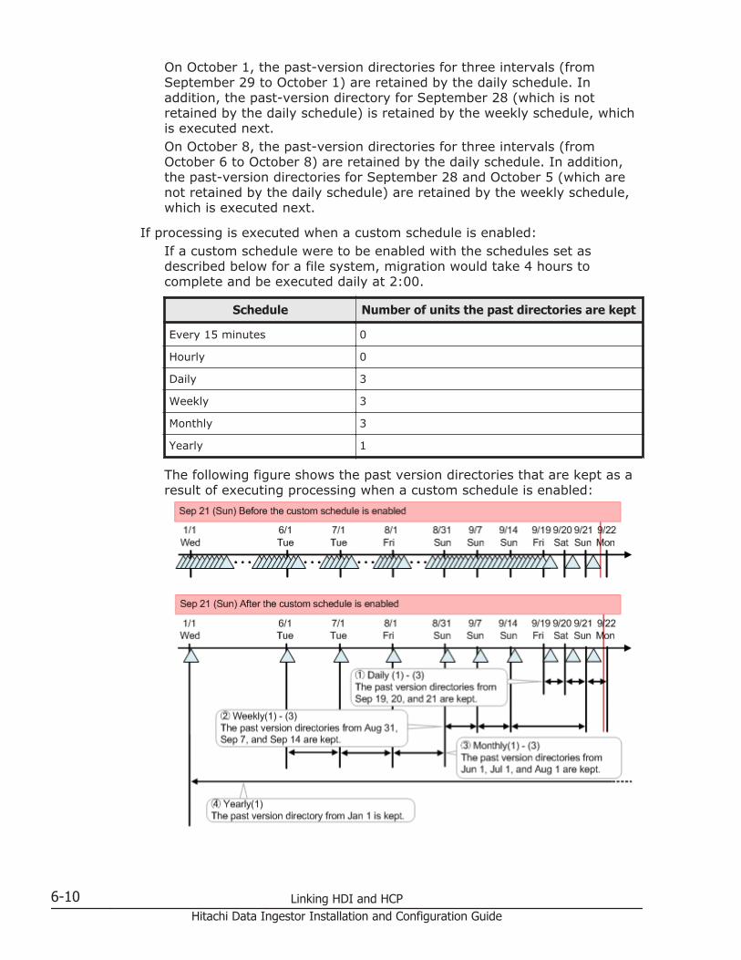
On October 1, the past-version directories for three intervals (fromSeptember 29 to October 1) are retained by the daily schedule. Inaddition, the past-version directory for September 28 (which is notretained by the daily schedule) is retained by the weekly schedule, whichis executed next.On October 8, the past-version directories for three intervals (fromOctober 6 to October 8) are retained by the daily schedule. In addition,the past-version directories for September 28 and October 5 (which arenot retained by the daily schedule) are retained by the weekly schedule,which is executed next.
If processing is executed when a custom schedule is enabled:If a custom schedule were to be enabled with the schedules set asdescribed below for a file system, migration would take 4 hours tocomplete and be executed daily at 2:00.
Schedule Number of units the past directories are kept
Every 15 minutes 0
Hourly 0
Daily 3
Weekly 3
Monthly 3
Yearly 1
The following figure shows the past version directories that are kept as aresult of executing processing when a custom schedule is enabled:
6-10 Linking HDI and HCPHitachi Data Ingestor Installation and Configuration Guide

The past-version directories for three intervals (from September 19 toSeptember 21) are retained by the daily schedule.In addition, the past-version directories for August 31, September 7, andSeptember 14 (which are not retained by the daily schedule) are retainedby the weekly schedule, which is executed next.Furthermore, the past-version directories for June 1, July 1, and August 1(which are retained by neither the daily nor the weekly schedule) areretained by the monthly schedule, which is executed next.Finally, the past-version directory for January 1 (which is not retained byany of the daily, weekly, or monthly schedules) is retained by the yearlyschedule.
What must be checked before linking an HDI system with anHCP system
Check the following points regarding operation of the file system from whichdata is to be migrated to an HCP system:
• Up to 10 KB is required in the management area per file when migratingdata to an HCP system. Take this into account when considering the filesystem capacity.
• When migration policies are set, the creation of hard links is automaticallydisallowed. File systems must be set to disallow hard link creation.
• If you change the settings to allow hard link creation, you can create hardlinks in file systems. Note that the hard links are migrated to the HCPsystem as one file. As a result, hard links are not restored when data isrestored from the HCP system to the HDI system.
• If a search is performed for files that have the offline attribute, because alarge amount of data will be recalled to the HDI system, processing mighttake a while and the maximum capacity of the file system might bereached.
• If the names of files or directories are changed, the processing forextracting files to be migrated will be affected. For this reason, if you tryto change a lot of file names, migration might take a long time.
• If you change the metadata of a file or directory, the metadata ismigrated to an HCP system. If you change the metadata of many files,such as for ACL changes, migration of metadata might take a long time.We recommend that you use groups for ACL operations, so that theimpact can be reduced even when changes are made to users.
• To prevent the used capacity of the file system from reaching themaximum, set a threshold value that starts changing files to stub files sothat the increased amount of data per hour does not exceed the unusedcapacity of the file system.
• To stop operations linking with an HCP system, if necessary, ask the HCPsystem administrator to delete the data in the corresponding namespace.
If you are migrating data at the share level, check the following:
Linking HDI and HCP 6-11Hitachi Data Ingestor Installation and Configuration Guide

• Allocate a namespace to shares created in a directory directly under themount point. When using the GUI, do not create file systems and sharesat the same time. Create the file system first, and then create shares andallocate namespaces.
• Do not move, by using FTP or other means, any created files ordirectories to within different shares. Files and directories moved in thisway might not be restored correctly.
• To allocate a namespace by editing a created share, you need to rebuildtask management information for the file system by using thearccorrection command. It might take time to complete this task.Therefore, it is recommended that you allocate a namespace whencreating a new share.
• For a WORM file system, you cannot end operation of a share for whichdata was migrated to the HCP system.
• To end operation of a share for which data was migrated to the HCPsystem, release the share, and then, if necessary, use the arcstdelcommand to delete the data in the directory and the mappinginformation. Before executing the arcstdel command, check thefollowing:
¢ Make sure that the subtree quota set for the directory under thetarget share is released.
¢ If you imported data from other file servers, after importing, makesure that the import definition information is deleted.
Check the following regarding the data to be migrated:
• In addition to regular files, directories and special files (excluding socketfiles) are subject to migration. Special files and directories are migratedregardless of the conditions set for migration policies.
• If a regular file meets any of the following conditions, it will not bemigrated even if it meets the conditions set in the migration policy.
¢ The file data has not been updated since it was migrated.
¢ The path length is more than 4,095 bytes.
¢ The file path contains a line feed code.
¢ Files in the .snaps, .history, and .lost+found directories.
¢ Files in directories that have the following names and that are locateddirectly under the file system:.arc, .system_gi, .system_reorganize, lost+found
¢ Files that have the following names and that are located directlyunder the file system:.backupdates, .temp_backupdates
Check the following regarding the settings for policies and schedules formigration tasks:
• A maximum of four migration tasks per resource group can be executedat the same time.
6-12 Linking HDI and HCPHitachi Data Ingestor Installation and Configuration Guide
• If migration policies have already been set for a file system but amigration is not performed for the file system for a long time, it will takea long time the next time a migration is performed. To avoid this,configure the settings so that a migration is performed on regular basisafter migration policies are set.
• To appropriately determine how often migration tasks are to be executedand the maximum number of past version directories to be retained,conditional expressions must be satisfied to prevent any timeouts thatmight occur if a failover occurs. The following inequality must be satisfiedwhen performing this check. If you use the arcconfedit command toconfigure the settings so that a past version directory is created onlywhen the first migration of the day is performed, you can calculate thesettable retention period of the previous versions of files by setting 1 fornumber-of-migration-tasks-executed-per-day in the inequality.
Examination cases are shown below.Examination case when disabling the custom scheduling of versionmanagement
¢ There is a file system that allows version-managed files to berestored.
¢ There are 10 shared directories in the file system that allows version-managed files to be restored.
¢ There are 5 destinations made available by the NFS protocol in eachshare.
¢ Previous versions of files are retained for 60 days.For these assumed settings, use the following inequality to determine theexecution interval for migration tasks:
Linking HDI and HCP 6-13Hitachi Data Ingestor Installation and Configuration Guide
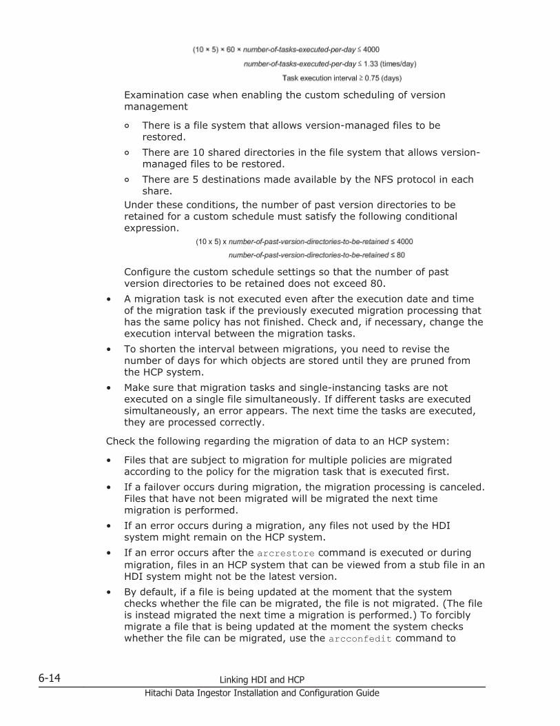
Examination case when enabling the custom scheduling of versionmanagement
¢ There is a file system that allows version-managed files to berestored.
¢ There are 10 shared directories in the file system that allows version-managed files to be restored.
¢ There are 5 destinations made available by the NFS protocol in eachshare.
Under these conditions, the number of past version directories to beretained for a custom schedule must satisfy the following conditionalexpression.
Configure the custom schedule settings so that the number of pastversion directories to be retained does not exceed 80.
• A migration task is not executed even after the execution date and timeof the migration task if the previously executed migration processing thathas the same policy has not finished. Check and, if necessary, change theexecution interval between the migration tasks.
• To shorten the interval between migrations, you need to revise thenumber of days for which objects are stored until they are pruned fromthe HCP system.
• Make sure that migration tasks and single-instancing tasks are notexecuted on a single file simultaneously. If different tasks are executedsimultaneously, an error appears. The next time the tasks are executed,they are processed correctly.
Check the following regarding the migration of data to an HCP system:
• Files that are subject to migration for multiple policies are migratedaccording to the policy for the migration task that is executed first.
• If a failover occurs during migration, the migration processing is canceled.Files that have not been migrated will be migrated the next timemigration is performed.
• If an error occurs during a migration, any files not used by the HDIsystem might remain on the HCP system.
• If an error occurs after the arcrestore command is executed or duringmigration, files in an HCP system that can be viewed from a stub file in anHDI system might not be the latest version.
• By default, if a file is being updated at the moment that the systemchecks whether the file can be migrated, the file is not migrated. (The fileis instead migrated the next time a migration is performed.) To forciblymigrate a file that is being updated at the moment the system checkswhether the file can be migrated, use the arcconfedit command to
6-14 Linking HDI and HCPHitachi Data Ingestor Installation and Configuration Guide

change the setting corresponding to the migrating of files that are beingupdated.Note that if the HCP system that is linked to is a version earlier than 4.1,files that are updated during a migration cannot be forcibly migrated.(The files are instead migrated the next time a migration is performed.)
• If files migrated to the HCP system are deleted from the file system,those files are also deleted from the HCP system. Deleted files can berestored from older versions of the data.
• Even if you set the hcpobjdelset command so that the data on HCP isasynchronously deleted when the files migrated to HCP are deleted fromthe file system, when there is insufficient file system capacity, thedeletion of data on HCP is synchronized with the deletion of files from thefile system. At this time, if communication with HCP fails, the files aredeleted from HDI but the data on HCP is not deleted. Check the HSM Corelog (hsmarc.log) to see if the KAQM37070-E message has been issued. Ifit has, check the content of the message and ask the HCP administratorto delete the data.
• When older versions of files migrated to an HCP system are madeavailable to a client, the WORM-related attribute and the last access dateand time (atime) and last updated date and time (ctime) might bedifferent between the file at the time of migration and the file inthe .history directory. However, the content of the files is the same.
• If older versions of files migrated to an HCP system are made available toa client and the time zone is changed, after restarting the node OS, thename of the directory under the .history directory that indicates thedate and time that the migration was performed will be changed to thedate and time in the new time zone.
• Files and directories that failed to be migrated cannot be viewed inthe .history directory or by other file systems that can view data via theHCP system. If this happens, files and directories are not displayed, orthey are displayed as 0-byte files and empty directories.
• After all of the files of the target file system are migrated, the directoriesare migrated. Even if the file migration completes, you cannot performrestorations if the migration of the parent directory is not completed. As aresult, if the migration processing is stopped in mid-transfer, all of thefiles might not be able to be restored. When you set the migration policy,specify the maximum duration value to have enough time to completemigrations. In addition, specify a value smaller than the maximumduration for communication timeouts with HCP systems so that processingis not stopped before migration of large files completes.
Check the following regarding the restoration of data that was migrated to anHCP system:
• When a directory that has not yet been restored is accessed for the firsttime, the data is restored from the HCP system on demand. If the numberof files or directories in the directory is large, restoring data takes a longtime. As a result, Explorer or other applications used on the client sidemight timeout. However, because the restoration processing will still
Linking HDI and HCP 6-15Hitachi Data Ingestor Installation and Configuration Guide
continue even if a timeout occurs, wait a while until the processingcompletes, and then access the target directory again.
• For file systems where restorations were performed, if you performoperations that recursively scan the directory (for example, searching allfiles, displaying the properties of Explorer, or using the Show pop-updescription for folder and desktop items function to display pop-ups),the processing takes a long time because data is restored for a largenumber of directories on demand. Therefore, do not perform operationsthat recursively scan the directory. Note that you can disable the Showpop-up description for folder and desktop items function by usingthe Folder Options dialog box of Explorer.
In addition, check the following points before linking with an HCP system.
• The total number of file systems and file shares connected to an HCPsystem cannot exceed 1,023.
• If the KAQM37038-E message was output to the HSM Core log file(hsmarc.log), enable version management (versioning) on the HCPsystem, and then perform the migration again.
• To change the configuration of a tenant that is linked to an HDI system ofa version earlier than 4.0.0-00 to share the tenant with multiple HDIsystems, install updates for all the HDI systems that will share the tenantbefore using the tenant with the HDI systems.
• Changing the time on the NTP server might restart the HCP system.Migration and recall processing fails while the HCP system is beingrestarted.
• If you use the fsexport or fsimport command when the file system fromwhich data is being migrated to an HCP system is connected to anothernode, the HCP linkage settings cannot be inherited. Perform the followingoperations depending on the file system settings. Note that a file systemlinked to the HCP system at the share level cannot be connected toanother node.
¢ For a file system that migrates data to the HCP system (non-home-directory-roaming file system)Check the migration policy settings in the Task Management dialogbox and the namespace settings in the Namespace tab in the file-system window. Afterwards, execute the fsexport command and thefsimport command, and then reconfigure migration by using theMigration Wizard.
¢ For a home-directory-roaming file systemPerform the following, instead of executing the fsexport command orthe fsimport command:
Migrate all data in the file system to an HCP system, re-create the filesystem on the connected node, and then execute the arcrestorecommand to restore the data in the re-created file system.
¢ For a file system that can access HCP data migrated from other HDIsystems as read-only
6-16 Linking HDI and HCPHitachi Data Ingestor Installation and Configuration Guide

Re-create the file system on the connected node, instead of executingthe fsexport command or the fsimport command.
Accounts used for accessing the HCP system from HDI systemsThe accounts used for accessing HCP tenants and namespaces from HDIsystems require data access permissions and tenant managementpermissions. Even with data access permissions, you cannot create or editnamespaces. Likewise, even with tenant management permissions, youcannot access namespace data, making it impossible to perform datamigrations or recalls.
The account management methods available differ depending on the HCPversion you are using.
For HCP version 5.0 or later
When the HCP system is set up by using the HDI configuration wizard, specifythe administrator information for the tenant created by using the HCPsystem. After the HCP system has been set up by using the configurationwizard, data access permissions are automatically created for the HCP tenantadministrator.
In addition, to share data migrated to the HCP system with other HDIsystems, you can create user accounts that have permission to access thedata in read-only mode. You can create these types of accounts when youuse the GUI to create or edit a file system or file share from which data is tobe migrated to the HCP system. Information about the created accounts canbe specified when creating a file system or file share that can access datamigrated to the HCP system from other HDI systems as read-only.
For HCP version 4.1 or earlier
Different accounts are required for tenant management and data access.
When the HCP system is set up by using the HDI configuration wizard, specifythe administrator information for the tenant created by using the HCPsystem. After the HCP system has been set up by using the configurationwizard, data access permissions are automatically created for the HCP dataaccess account.
Because the HCP system is already linked to, if the data access account is setup in the HDI system, but the tenant administrator information is not set inthe HDI system, perform either of the following:
• Create a user account for the tenant administrator by using the samename and password as the data access account.Ask the HCP administrator to do this, or refer to the manual of the HCPversion you are using.
• Obtain the necessary information from the HCP administrator, and thenspecify the tenant administrator information yourself by using the HDIconfiguration wizard.
Linking HDI and HCP 6-17Hitachi Data Ingestor Installation and Configuration Guide

In addition, to share data migrated to the HCP system with other HDIsystems, you can create data access accounts that have permission to accessthe data in read-only mode. You can create these types of accounts when youuse the GUI to create or edit a file system or file share from which data is tobe migrated to the HCP system. Information about the created accounts canbe specified when creating a file system or file share that can access datamigrated to the HCP system from other HDI systems as read-only.
Settings required on the HCP system when linking with the HCPsystem
This section describes the settings required on the HCP system when linkingan HDI system with the HCP system.
Creating a tenant
Before setting up the HDI system, configure an HCP environment and preparea tenant to be assigned to the HDI system. Ask the HCP administrator toprepare a tenant, or prepare a tenant yourself by referring to the HCPdocumentation.
The settings below are required to link an HDI system with the HCP system.For all other settings, use the defaults.
• Set the Monitor, Administrator, Compliance, and Security roles for theuser account.
• Set a hard quota for the tenant capacity.
• Specify the settings so that the retention mode can be selected.
• Enable versioning.
• If the version of the linked HCP system is 4.1 or later, specify a value ofat least number-of-file-system-namespaces + 1 for the namespace quota.
• Enable the HCP management API (MAPI).
Creating a migration-destination namespace
A namespace is automatically created if the namespace information of an HCPsystem is set by using the GUI. Ask the HCP administrator to create anamespace or create it yourself by referring to the HCP documentation.
The settings below are required to migrate data on an HDI system. For allother settings, use the defaults.
Note that the default namespace cannot be used if an HDI system is linked.
• Set a hard quota for the namespace capacity.
• Select enterprise mode for the retention mode.
• Enable versioning and set a time for version pruning appropriate forsystem operation.In an HDI file system, data from older versions that was migrated to anHCP system is made available to clients by default. When making datafrom older versions available, set a time for version pruning 1 day longer
6-18 Linking HDI and HCPHitachi Data Ingestor Installation and Configuration Guide

than the period to hold for HDI versions (the default HDI period to hold is7 days). To make data from older versions unavailable, set the time forversion pruning to 2 days.
• Configure the settings so that custom metadata can be added, replaced,and deleted for objects still within their time for version pruning.
• If the version of the linked HCP system is 5.0 or later, enable allnamespace permissions for the user account (Read, Write, Delete,Purge, Privileged, and Search).
• If the version of the linked HCP system is 4.1 or earlier, create a dataaccess account.
• Retention Class is not set.
If you are using the WORM functionality, configure the setting in the HDIsystem.
In addition to the above settings, you need to set the namespace capacity.Use the following formula to estimate the maximum capacity of thenamespace, and then determine the namespace capacity to set.maximum-namespace-capacity = total-capacity-of-user-data-to-be-stored + total-capacity-of-files-to-be-updated-in-a-day X period-to-hold-the-older-versions
To change the level at which namespaces are assigned from file systems tofile shares, use the arcrestore command. Use this command to move thedata of the file system linked to the HCP system at the file system level to adirectory within a file system set to link to the HCP system at the share level.
Note:
• Do not create shares in the migration-destination directory beforeexecuting the arcrestore command.
• If, in the share directory at the migration-destination, you will make olderversions of files migrated to an HCP system available to clients,reconsider the retention period for past data.
• Ask the end users not to access the file systems that will be operated on.
• If you delete the data in a file system before deleting that file system, thedata migrated to the HCP system is also deleted. For this reason, ask theend users not to delete any data that exists within the applicable filesystem and that needs to be migrated.
The procedure for changing the level at which namespaces are assigned fromfile systems to file shares is described below.
1. Run the archcpget command by specifying the --migrate-info option.
Record the name of the migration-destination namespace of theapplicable file system.
2. Record the file share information.Run either the cifslist or nfslist command, and record the CIFS orNFS share information.
Linking HDI and HCP 6-19Hitachi Data Ingestor Installation and Configuration Guide
To you want to be able to restore information about multiple file shares atonce, execute the cifsbackup or nfsbackup command to back up theinformation about the CIFS or NFS shares at the file system level.
3. For CIFS shares, use the cifsoptlist command and record theinformation set for the CIFS shares.
4. Use the cifsdelete or nfsdelete command to delete all file shareswithin the applicable file system.
5. Use the GUI to change the schedule for migration tasks of the applicablefile system so that the tasks are executed immediately.
6. Use the GUI to verify that the migration task in step 5 was successful.If migration of any files or directories failed, identify the cause of thefailure, take the appropriate action, and then execute the task again.
7. Use the fsumount command to unmount the file system.
8. Use the fsdelete command to delete the file system.
9. Use the GUI to prepare a file system that is set to link to an HCP systemat the share level.To make data of past versions that was migrated to an HCP systemaccessible to clients, set the retention period for past data when creatingor editing a file system, so that the required data in the .historydirectory in step 12 is also recovered.
10. Use the dircreate command to create a directory for namespaceallocation directly under the mount point of the file system.Do not create file shares.
11. To set a subtree quota, use the stquotaset command to set the requiredinformation.
12. Use the arcrestore command to restore, to the directory created in step10, the data that was migrated to the HCP system.Specify the options as follows:arcrestore --namespace name-of-namespace-recorded-in-step-1 --file-system name-of-file-system-prepared-in-step-9 --dir name-of-directory-created-in-step-10
13. Create file shares corresponding to the directory created in step 10.Based on the CIFS or NFS information recorded in step 2, execute thecifscreate or nfscreate command to create the file shares.
To restore information about multiple file shares at once, execute thecifsrestore or nfsrestore command to output a template file for therestoration script. Edit the share directory path specified in the templatefile by following the example below. Then, execute the script to restoreinformation about the CIFS and NFS shares.The following is an example of editing a template file for restoringinformation about CIFS shares, where the names of the applicable filesystems and directory are as follows:
¢ Name of the migration-source file system: fs01¢ Name of the migration-destination file system: fs02
6-20 Linking HDI and HCPHitachi Data Ingestor Installation and Configuration Guide

¢ Name of the migration-destination directory: dirA, which is directlyunder the mount point
Template file before being revised
$PRECMD sudo cifscreate -x cifsshare01 -d \/mnt\/fs01 -c ......$PRECMD sudo cifscreate -x cifsshare01 -d \/mnt\/fs01\/dir01 -c ...
Template file after being revised
$PRECMD sudo cifscreate -x cifsshare01 -d \/mnt\/fs02\/dirA -c ......$PRECMD sudo cifscreate -x cifsshare01 -d \/mnt\/fs02\/dirA\/dir01 -c ...
14. For CIFS file shares, use the cifsoptset command to change the CIFSshare settings based on the information recorded in step 3.
If the data of the file system for which the level at which namespaces areallocated was changed is being made available to another HDI system, youneed to create, on that HDI system, a new file system linked to the HCPsystem at the share level, and then restore the HCP system data. If the levelat which namespaces are allocated differs, you will not be able to view themost recent data that was migrated to the HCP system.
Creating a namespace for saving system settings
A namespace for saving system settings (system-backup-data) isautomatically created when the HCP system is configured from the setupwizard of the HDI system.
The settings below are required to save system settings. For all othersettings, use the defaults.
• Specify system-backup-data as the namespace name.
• Specify a hard quota for the namespace capacity as follows:total-number-of-systems-using-tenants# x 1 GB#: This is equal to the total of the number of HDI systems in single-nodeand cluster configurations in those configurations.To import data from another file server to a file system linked to the HCPsystem at the share level, ensure that enough space is available byadding the capacity to be used for the imported data to the hard quota forthe capacity of the namespace of the location in which system settingsare normally saved. You can use the following formula to estimate thecapacity that will be used by the data to be imported:number-of-files-and-directories-to-be-imported x average-path-length-for-import-source-sharesFor example, when there are 10 million files and directories to beimported, and the average path length is 256 bytes, add 2.38 GB to thevalue to be specified as the hard quota.
• Select enterprise mode for the retention mode.
• Enable versioning and set a time for version pruning appropriate forsystem operation.
Linking HDI and HCP 6-21Hitachi Data Ingestor Installation and Configuration Guide
• If the version of the linked HCP system is 5.0 or later, enable allnamespace permissions for the user account (Read, Write, Delete,Purge, Privileged, and Search).
• If the version of the linked HCP system is 4.1 or earlier, create a dataaccess account.
When using the replication functionality
If a failure occurs on a primary HCP system, the HCP replication function canbe used to recall a file from the replica HCP system to the corresponding stubfile on the HDI system.
To use the replication functionality on the HCP system after a migration tothe HCP system has been started, the replication functionality must beenabled for all the namespaces, including the namespace that contains thesystem settings file (system-backup-data).
When upgrading software on a node by using an installation file on HCP
In a single-node HDI configuration, you can use an installation file that hasbeen stored in HCP to upgrade the software on the node. Follow thedirections below to store in HCP the installation file stored on the installationmedia.
Note: Register the installation file for each tenant that is assigned to the HDIsystem.
1. Obtain the necessary installation files from the HDI installation media.See Obtaining the necessary files on page 6-22.
2. Create a namespace to store the installation files.See Creating a namespace on page 6-23.
3. Set data access permissions for the user accounts.See Setting the data access permissions for user accounts on page 6-23.
4. Store the installation files in the namespace.See Storing the installation files on page 6-23.
5. Add custom metadata to the installation files stored in the namespace.See Adding custom metadata for the installation file on page 6-25.
6. Use the installation files stored in HCP to install updates for the softwarerunning on the node.See the Administrator's Guide.
Obtaining the necessary files
Obtain the installation files and the version management file from the HDIinstallation media. The following files are required for an update installation:
• install_files.tar.gz• install_files.tar.gz.md5• version.xml
6-22 Linking HDI and HCPHitachi Data Ingestor Installation and Configuration Guide

Creating a namespace
The namespace settings that are required for storing the installation file areas follows:
• system-install is set as the namespace name.
• MD5 is set for Hash Algorithm.
• Version management (Versioning) is enabled, and in Prune versionsolder than, 0 is set to both Primary System and Replica System (ifreplicating).
• For the capacity (Hard Quota) of the storage to be allocated in thenamespace, the following value (units: GB) is specified:value-selected-to-'DPL' x 2
Setting the data access permissions for user accounts
Set the data access permissions for the user account that is used to operatethe installation files, and the user account that is used to access the clientfrom HDI.
Enable the Browse, Read, Write, Delete, and Purge namespace permissions(Assign Data Access Permissions for Selected Namespaces).
If the primary HCP system is version 5.0 or later, and the replica HCP systemversion is 4.x, do not select Change Owner.
Storing the installation files
The following is the procedure to use the curl command from a client tostore the installation files in the namespace:
1. On the client where you will execute the curl command, save theinstallation files (install_files.tar.gz andinstall_files.tar.gz.md5).
2. Generate a Base64-encoded user name and a MD5-hashed password.
Base64-encoded user nameUse Base64 to encode the user name for the user account that youuse to access the namespace. Use a general Base64 encoding tool togenerate the user name.The following is an example of a Base64-encoded user name:
MD5-hashed passwordUse MD5 to hash the user name for the user account that you use toaccess the namespace. Use a general MD5 hashing tool to generatethe user name.The following is an example of a MD5-hashed password:
Linking HDI and HCP 6-23Hitachi Data Ingestor Installation and Configuration Guide

3. If any installation files are already stored in the target namespace, deletethe installation files.Execute the following command:
curl -k -iX DELETE -b "hcp-ns-auth=Base64-encoded-user-name:password-created-from-the-MD5-hashing-function" "https://system-install.tenant-name.HCP-host-name (FQDN)-or-IP-address/rest/system/HDI/install_files.tar.gz?purge=true"
The following is an example of the execution for the command:
# curl -k -iX DELETE -b "hcp-ns-auth=c3RhcnQ=:a3b9c163f6c520407ff34cfdb83ca5c6" "https://system-install.system-tenant.vm07.hcp.local/rest/system/HDI/install_files.tar.gz?purge=true"HTTP/1.1 200 OKSet-Cookie: hcp-ns-auth="c3RhcnQ=:A3B9C163F6C520407FF34CFDB83CA5C6";Version=1;Path=/;Domain=vm07.hcp.local;DiscardExpires: Thu, 01 Jan 1970 00:00:00 GMTX-HCP-ServicedBySystem: vm07.hcp.localX-RequestId: 73B37EEA1A6A85X-HCP-Time: 1382409961Content-Length: 0
4. Store the installation files in the namespace.Execute the command below. The execution results for the command areoutput to result.txt.
curl -k -# -b "hcp-ns-auth=Base64-encoded-user-name:password-created-from-the-MD5-hashing-function" -iT storage-location-for-installation-files-saved-in-step-1 "https://system-install.tenant-name.HCP-host-name (FQDN)-or-IP-address/rest/system/HDI" > result.txt
Below is an example of the execution for the command. The progress isdisplayed during the execution, and the progress reaches 100% when theexecution is completed.
# curl -k -# -b "hcp-ns-auth=c3RhcnQ=:a3b9c163f6c520407ff34cfdb83ca5c6" -iT /HDI/install_files.tar.gz "https://system-install.system-tenant.vm07.hcp.local/rest/system/HDI/" > result.txt####### 10.8%
5. Make sure that the hash values for the installation files that were saved instep 1 are the same as the hash values in result.txt that was output instep 4.When you compare the hash values, note that they are not case-sensitive. If the values are different, repeat the procedure from step 1.The following is an example of the hash values to be checked:
6-24 Linking HDI and HCPHitachi Data Ingestor Installation and Configuration Guide
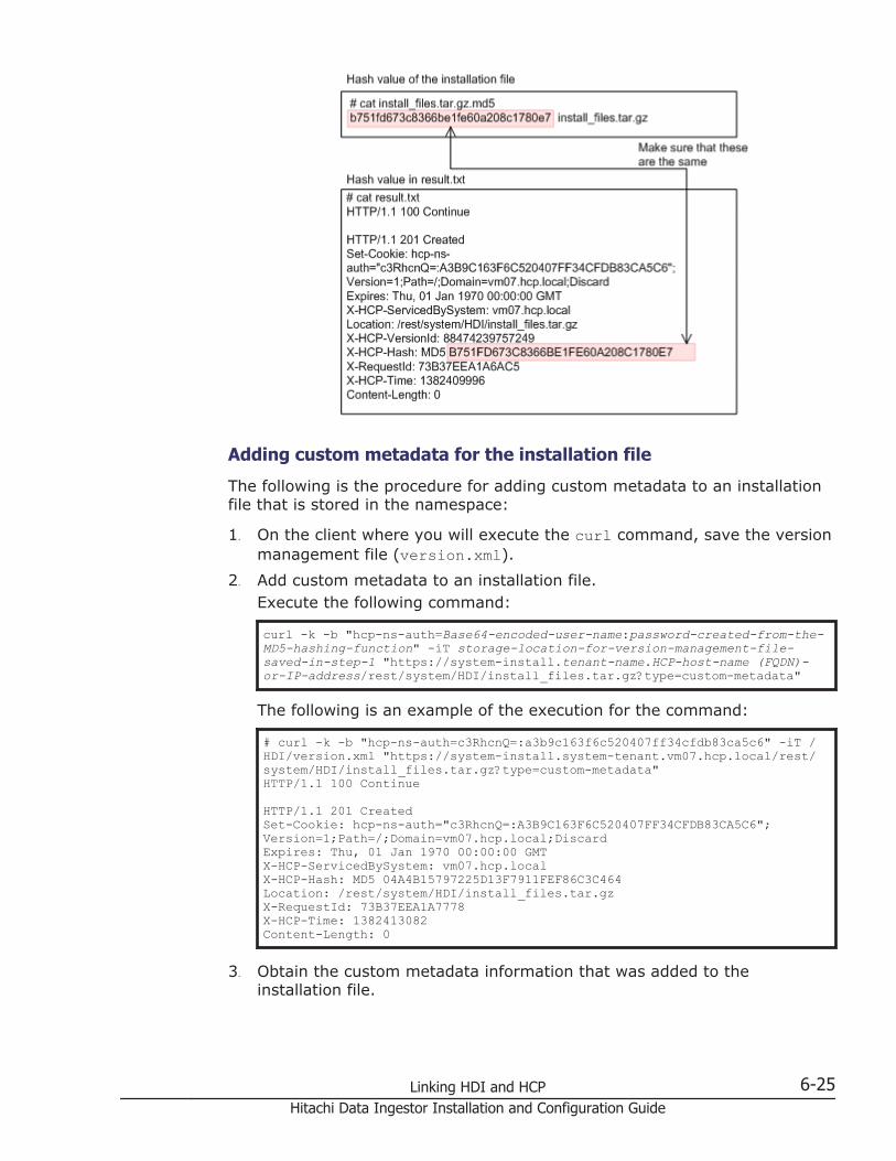
Adding custom metadata for the installation file
The following is the procedure for adding custom metadata to an installationfile that is stored in the namespace:
1. On the client where you will execute the curl command, save the versionmanagement file (version.xml).
2. Add custom metadata to an installation file.Execute the following command:
curl -k -b "hcp-ns-auth=Base64-encoded-user-name:password-created-from-the-MD5-hashing-function" -iT storage-location-for-version-management-file-saved-in-step-1 "https://system-install.tenant-name.HCP-host-name (FQDN)-or-IP-address/rest/system/HDI/install_files.tar.gz?type=custom-metadata"
The following is an example of the execution for the command:
# curl -k -b "hcp-ns-auth=c3RhcnQ=:a3b9c163f6c520407ff34cfdb83ca5c6" -iT /HDI/version.xml "https://system-install.system-tenant.vm07.hcp.local/rest/system/HDI/install_files.tar.gz?type=custom-metadata"HTTP/1.1 100 Continue HTTP/1.1 201 CreatedSet-Cookie: hcp-ns-auth="c3RhcnQ=:A3B9C163F6C520407FF34CFDB83CA5C6";Version=1;Path=/;Domain=vm07.hcp.local;DiscardExpires: Thu, 01 Jan 1970 00:00:00 GMTX-HCP-ServicedBySystem: vm07.hcp.localX-HCP-Hash: MD5 04A4B15797225D13F7911FEF86C3C464Location: /rest/system/HDI/install_files.tar.gzX-RequestId: 73B37EEA1A7778X-HCP-Time: 1382413082Content-Length: 0
3. Obtain the custom metadata information that was added to theinstallation file.
Linking HDI and HCP 6-25Hitachi Data Ingestor Installation and Configuration Guide

Execute the command below. The execution results for the command areoutput to result_custom.txt.
curl -k -b "hcp-ns-auth=Base64-encoded-user-name:password-created-from-the-MD5-hashing-function" -i "https://system-install.tenant-name.HCP-host-name (FQDN)-or-IP-address/rest/system/HDI/install_files.tar.gz?type=custom-metadata" > result_custom.txt
The following is an example of the execution for the command:
# curl -k -b "hcp-ns-auth=c3RhcnQ=:a3b9c163f6c520407ff34cfdb83ca5c6" -i "https://system-install.system-tenant.vm07.hcp.local/rest/system/HDI/install_files.tar.gz?type=custom-metadata" > result_custom.txt % Total % Received % Xferd Average Speed Time Time Time Current Dload Upload Total Spent Left Speed 100 426 100 426 0 0 5388 0 --:--:-- --:--:-- --:--:-- 416k
4. Make sure that the custom metadata in the version management file thatwas saved in step 1 is the same as the custom metadata inresult_custom.txt that was output in step 3.
The following is an example of the custom metadata to be checked:
6-26 Linking HDI and HCPHitachi Data Ingestor Installation and Configuration Guide

Sharing HCP data migrated from other HDI systems as read-onlyWhen referencing HCP data migrated from other HDI systems to make thedata accessible as read-only, the system administrators of the HDI systemsfrom which the data is migrated to the HCP system and the systemadministrator of the HDI system on which HCP data migrated from other HDIsystems is made accessible as read-only must work together.
To share HCP data migrated from other HDI systems as read-only:
1. Create a file system to which data is migrated on the HCP system, andthen create a file share on the file system.The operations are performed by the system administrator of the HDIsystem from which data is migrated to the HCP system.
2. Migrate the data in the file system that was created in step 1 to the HCPsystem.
3. Share the HCP data that was migrated from the HDI system as read-only.Create a file system that has access to HCP data migrated from other HDIsystems as read-only. Then, create a file share on the file system. Set theinformation for the namespace to which data is migrated. Set thefollowing settings so that they are the same as those for the file systemthat was configured in 1.:
¢ ACL type of the file system
¢ Settings related to the WORM functionality
¢ Level at which namespaces are allocated (file systems or shares)For allocation at the share level, create shares in the directory directlyunder the mount point, and then assign namespaces.
¢ Threshold at which stub processing is performed
¢ CIFS and NFS share informationThe capacity required by a file system differs depending on the level atwhich namespaces are allocated. For allocation at the file system level,set the same capacity as that of the file system created in step 1. Forallocation at the share level, specify a capacity equal to or greater thanthe total capacity occupied by the user data stored in all namespaces thatare accessible from the file system.In addition, mount the file system with both the read and writepermissions.These operations are performed by the system administrator of the HDIsystem on which HCP data migrated from other HDI systems is accessibleas read-only.For details about how to share HCP data migrated from other HDIsystems as read-only, see the Administrator's Guide.
In addition, note the following points when sharing HCP data migrated fromother HDI systems as read-only:
• Data sometimes cannot be properly referenced by a location becauseshortcuts and symbolic links in Windows are dependent on theconfiguration of the file system they were created in.
Linking HDI and HCP 6-27Hitachi Data Ingestor Installation and Configuration Guide

• HDI system version 03-01-00-00 or later must be used at all of the sitessharing data.
• Manage user information by using an external authentication server, anduse the same user information for each HDI system.
• Note that data must have been migrated to the HCP system before youcan attempt to share that data with other HDI systems as read-only. Ifthe file system that contains the data to be shared as read-only ismounted before the data is migrated, the KAQM37250-E message isissued via an SNMP trap or email. If the KAQM37250-E message is issued,either wait until the migration is performed, or ask the systemadministrator of the HDI system from which the data is to be migrated tothe HCP system to immediately perform a migration.
• When editing file share attributes or deleting file shares on the file systemfrom which data is migrated to the HCP system, the relevant settings forthe HDI system used for data sharing need to be changed. The systemadministrator of the HDI system from which the data is migrated to theHCP system must inform the system administrator of HDI system onwhich HCP data migrated from the other HDI system is accessible asread-only of the changes. The informed system administrator mustchange the settings on file shares according to the information.
If HCP data will no longer be shared, the system administrators of therelevant HDI systems must perform the following:
The system administrator of the HDI system from which the data is migratedto the HCP system must inform the system administrators of the HDI systemsfor sharing HCP data migrated from other HDI systems that data sharing willbe stopped. The system administrator of the HDI system from which the datais migrated must then change the settings of the accounts used for accessingthe namespace from other HDI systems. The system administrator of eachHDI system must change the settings for file systems or file shares anddelete file systems or file shares.
Allowing another HDI to use migrated HCP data for each end userWhen migrating data in a file system to an HCP system, data created in thehome directory for each end user who uses the CIFS protocol for access canbe used from an HDI that is different from the HDI that is normally used bythe end user (home-directory-roaming functionality). A file system wheredata in the home directory can be used by another HDI is referred to as"home-directory-roaming file system".
To use home-directory-roaming functionality, make sure that HDI systemversion 4.1.0-00 or later is linked with HCP version 4.1 or later.
The following figure shows the data flow when migrated HCP data is usedfrom another HDI for each end user.
6-28 Linking HDI and HCPHitachi Data Ingestor Installation and Configuration Guide

Figure 6-5 Data flow when migrated HCP data are used from another HDIfor each end user
Data between HDIs are automatically synchronized. After an end user edits afile, updated data is migrated to HCP, and then the updated data is used toupdate data in the other HDI. Data is migrated every hour.
The home-directory-roaming file system must be accessed from CIFS clients.
Linking HDI and HCP 6-29Hitachi Data Ingestor Installation and Configuration Guide

Notes on allowing migrated HCP data to be used from another HDI for each enduser
This subsection includes notes to keep in mind when creating a system toallow migrated HCP data to be used from another HDI for each end user.
Note the following points about HCP tenants and namespaces to be used:
• Specify the same tenant used for the migration destinations for all thelinked HDI systems.
• When manually creating a namespace, you need to check, and ifnecessary, revise the number of days for which objects are stored untilthey are pruned. Ask the HCP system administrator to perform this task.
• If you use the home-directory-roaming functionality, HCP issues themessage below regarding a compliance event. This message is issuedduring normal processing, and does not indicate a problem.Privileged purge succeeded for object /management/hdr/lock/user-name.lock, Reason:unlock_of_homedirectory_resource.. Namespace: namespace-name
Note the following points about the HDI systems, the home-directory-roaming file system, and the file share:
• Allocate namespaces for the migration destinations at the file systemlevel.
• You cannot make migrating data in a home-directory-roaming file systemto an HCP system accessible as read-only.
• The following functionality is unavailable for the home-directory-roamingfile system:
¢ Converting the file system to a hierarchical structure
¢ Using single instancing
¢ Using the WORM functionality
¢ Managing subtree quotas
¢ Using the NDMP functionality
¢ Importing data from other file servers
• For real-time scanning, use a Symantec or McAfee antivirus program.Real-time scanning cannot be performed by a Trend Micro antivirusprogram on files in the home-directory-roaming file system.
• Do not change migration policy settings related to the conditions ofmigrated files. When the home-directory-roaming file system is created,appropriate migration policies are set by default so that all the data in thefile system is migrated to HCP.
• We recommend that one home-directory-roaming file system be used foreach HDI system. Also, when you create a home-directory-roaming filesystem, make sure that no more than four single-instancing andmigration tasks are simultaneously run for one resource group.
• A maximum of 1,000 end users can use the home-directory-roaming filesystem.
6-30 Linking HDI and HCPHitachi Data Ingestor Installation and Configuration Guide

If the number of end users who use the home-directory-roaming filesystem or the number of files to be created or updated increases,migration cannot complete within one hour, and the time span that thehome directory in another HDI system remains read-only is longer. Adjustthe number of end users and files to ensure that migration can becompleted within one hour.
• When an end user is accessing a home directory, the home directory thatthe same user is using in another HDI is read-only.
• If you need to stop the HDI system for routine maintenance, notify theend users in advance to stop accessing the home directory from the HDIsystem to be stopped, and then migrate all of the data in the home-directory-roaming file system to the HCP system. If you do not migratethe data to the HCP system, the update information is not applied to thehome directory of the other HDI system. As a result, end users cannotuse the most up-to-date files in the home directory of the other HDIsystem.In order to stop access to the home-directory-roaming file system, stopthe CIFS service in the Access Protocol Configuration dialog box. Thenuse the Task Management dialog box to migrate all files to HCP. Whenthe migration is complete, use the Check for Errors dialog box toconfirm that no migration-related error occurred. If an error occurred,keep executing the migration tasks until no error occurs.
Note the following about client authentication and accounts:
• For client authentication, use Active Directory authentication. Use usermapping to assign user IDs or group IDs. The same user ID or group IDmust be assigned to the account in all the HDI systems.
• Some names cannot be used as user account names. They are the sameas the user names that cannot be used when using the automatic homedirectory creation functionality. For details about the user names thatcannot be used when using the automatic home directory creationfunctionality, see the File System Protocols (CIFS/NFS) Administrator'sGuide.
• Data in the home directory becomes inaccessible if you change the username of an account. If you need to change a user name, you must createa new account.
The system administrator must inform the CIFS administrator of the followingnotes:
• Do not create files or directories immediately under shared directories.
• Access only the home directories of the users or groups for which you areassigned as the CIFS administrator. Data inconsistency may occur acrossHDIs if you access home directories of other users and update the data.
• Do not change the access privileges for home directories.
• Do not rename or delete the home directory. To delete all the data, selectand delete the files and subdirectories in the home directory.
In addition, the system administrator must inform the end user who uses thehome-directory-roaming file system of the following:
Linking HDI and HCP 6-31Hitachi Data Ingestor Installation and Configuration Guide

• Assign a network drive to the share of the home-directory-roaming filesystem, and then start access. If you assign only a host name and thenaccess HDI, the end user may be unable to manipulate the homedirectory.
• Use a user account that is common among the HDI systems. Make surethat user accounts are not shared by end users.
• To prevent data from failing to update on other HDI systems, log off fromthe client machine after finishing a task.
• Sometimes the home directory temporarily becomes read-only. If you areunable to save a file, temporarily save the file to the client computer.Wait a while, and then update the file in the home directory. If you stillcannot update the file, contact the system administrator.
• The home directory might temporarily be empty or contain outdated filesor directories. In addition, the client might fail to update files. If such aproblem occurs, save any files that should have been updated on theclient computer temporarily, log off, wait for about ten minutes, and thenretry access.The file in the home directory might have been updated. Compare this filewith the temporarily saved file before updating it.
• If updated content is not being applied to the file in the home directory,the updated file might be stored in the .conflict directory. Checkthe .conflict directory to verify that it does not include any updated file.Data in the .conflict directory is automatically deleted when the periodto hold the data expires. If the .conflict directory is created, checkwhether there are any necessary files as soon as possible.
• Specify settings so that all files and folders are displayed to enableviewing of the .conflict directory.
• If you want to use files in the .conflict directory, you must copy thefiles and place them in a location in the home directory other thanthe .conflict directory before using them. Do not copy the directorywhen copying the files you want to use. If you copy the directory, accessprivileges of the files may not be assigned as intended.
• When changing the access privileges of the home directory, you must notassign any access privilege that allow other users to update data.
General considerations before configuring and using home-directory-roaming
To allow migrated HCP data to be used from another HDI for each end user,the HDI system administrators at the various locations must work together.
The system administrator must perform the following tasks requiredto allow migrated HCP data to be used from another HDI for each enduser:
1. On the HDI system at each location, create a home-directory-roaming filesystem, and then create a file share.Make sure that the following settings are identical across all the linkedHDIs:
6-32 Linking HDI and HCPHitachi Data Ingestor Installation and Configuration Guide

¢ Timestamps of nodes
¢ Settings for client authentication
¢ Settings for file systems (such as ACL types, the period to hold thedata for earlier versions, and functions to be used)
¢ Namespace for the migration destinationsIf an HDI system administrator creates a namespace when creating a filesystem by using the GUI, the administrator must inform the systemadministrators of other HDI systems of the namespace name.Use the information provided by the HCP administrator if the HCPadministrator creates the namespace where data can be accessed from allthe HDIs.
2. Tell the end user to assign a network drive to the share for the home-directory-roaming file system, and then start access.
Note: If data migration from HDI to HCP fails because of a communicationfailure with HCP or for some other reason, a read-only directorynamed .conflict might be created in the home directory. The .conflictdirectory contains a subdirectory whose name indicates the date and timethat migration failed and the HDI system where the migration failed. Thissubdirectory contains the files that caused the migration failure. Ask the enduser to view the .conflict directory if updates are not reflected in the filesin the home directory. The data in the .conflict directory can be viewed oneach HDI system because the data is migrated the next time a migration isperformed.Files are retained in the .conflict directory for four days by default. Theperiod to hold the data can be changed by using the arcconfedit command.Change the settings of the period to hold the data in the same way for alllinked HDIs.
Using data migrated to the HCP system to recover an HDI systemIf an HDI system is linked with an HCP system, a batch operation can beperformed to restore the system settings information and user data if aproblem occurs on an OS disk, the cluster management LU, or a user LU inthe HDI system. Confirm that all files are subject to migration and the systemsettings information file is periodically saved to an HCP system. The systemsettings information file is saved with the name sysbk_ID-automatically-assigned-to-HDI-system.1 or sysbk_ID-automatically-assigned-to-HDI-system.2 in the HCP namespace used for storing system settings information(system-backup-data).
Note that you cannot restore the information below because the informationbelow is not saved to HCP systems. Record the settings information asnecessary.
• The configuration information for the file system that was not mountedwhen saving the information, including:
¢ The minimum and maximum retention periods
¢ The autocommit settings
Linking HDI and HCP 6-33Hitachi Data Ingestor Installation and Configuration Guide

¢ Whether to issue warning messages regarding file system capacityshortages
¢ Whether to enable the automatic failover functionality in the event ofa file system becoming blocked
¢ Whether to record file creation dates and times
• Settings information of the initial mode that is used when executingmigration tasks or single-instancing tasks
• User data that has not been migrated to an HCP system
• The configuration information for 64-bit inodes
Restored file systems are set to disallow creation of hard links.
In addition, you need to back up the following information to storage mediathat is external to the system every time the following information isupdated:
Storage system configuration informationIf the storage system being used is in the Hitachi AMS2000 series or theHUS100 series, use Hitachi Storage Navigator Modular 2 to download thefollowing settings information:
¢ Configuration information file for parity groups and logical units
¢ Configuration information file for port information
¢ Configuration information file for system parametersFor details on how to use Hitachi Storage Navigator Modular 2, see theHitachi Storage Navigator Modular 2 manuals.
File system informationOn the node on which the resource group containing the target filesystem is running, execute the fslist command with the -t and -woptions specified, and make a record of the displayed file system settingsinformation.
CIFS and NFS share informationUse the cifsbackup and nfsbackup commands to back up CIFS and NFSshare information. If both CIFS shares and NFS shares have been set upin a file system, you need to execute both the cifsbackup and nfsbackupcommands.
Correspondence with namespacesRecord the relationship between namespaces and file systems or fileshares. If a namespace is created automatically after you use the GUI toset the namespace information of an HCP system, the namespace is givena name automatically in the format given below.
For namespaces allocated to the file system:file-system-name-ID-automatically-assigned-to-HDI-system
For namespaces allocated to the share:file-system-name-ID-automatically-assigned-to-HDI-system-string-specified-by-user-when-namespace-was-allocated
6-34 Linking HDI and HCPHitachi Data Ingestor Installation and Configuration Guide

7Installing Hitachi File Services Manager
and Setting Up Its Environment
This chapter describes how a system administrator can install Hitachi FileServices Manager and set up the environment on the management serverwhen running an HDI system in a cluster configuration.
□ Installing and uninstalling Hitachi File Services Manager
□ Installing and uninstalling Hitachi File Services Manager (if themanagement server is running in a cluster configuration)
□ Starting and stopping Hitachi File Services Manager
□ Managing the system administrator account
□ Setting up the Hitachi File Services Manager environment
□ Maintenance of the management server
Installing Hitachi File Services Manager and Setting Up Its Environment 7-1Hitachi Data Ingestor Installation and Configuration Guide
Installing and uninstalling Hitachi File Services ManagerThe following sections describe how to install and uninstall Hitachi FileServices Manager.
Before installation:
¢ See Prerequisites for installing Hitachi File Services Manager on page7-12.
¢ If the management server is running in a cluster configuration, seeInstalling and uninstalling Hitachi File Services Manager (if themanagement server is running in a cluster configuration) on page7-15.
Performing a new installation of Hitachi File Services ManagerThis section describes how to perform a new installation of Hitachi FileServices Manager.
To perform a new installation of Hitachi File Services Manager:
1. Insert the installation media for Hitachi File Services Manager.If you want to copy the contents of the installation media, you must copythem to a local disk of the management server. You cannot perform aninstallation by using data on the network drive.
2. Use Explorer to view the contents of the installation media, and thenexecute HFSMinst.exe.
The license agreement dialog box appears.If a Hitachi Command Suite product has already been installed in the rootof a disk drive, the installation process will be interrupted. To preventthis, uninstall the Hitachi Command Suite product or re-install the HitachiCommand Suite product in a directory other than the root of a disk drive,and then install Hitachi File Services Manager.
3. Read the terms, and then click the Yes button.The Welcome to the Installation of Hitachi File Services Manager(New Installation) dialog box appears.
7-2 Installing Hitachi File Services Manager and Setting Up Its EnvironmentHitachi Data Ingestor Installation and Configuration Guide

Figure 7-1 Welcome to the Installation of Hitachi File ServicesManager (New Installation) dialog box
Note:When you click the Next button, the installer stops the services of HitachiCommand Suite Common Component and other Hitachi Command Suiteproducts.
4. Check the information displayed in the dialog box, and then click theNext button.The operation to be performed after you click the Next button dependson whether Hitachi Command Suite products have been installed on thecomputer on which you are installing Hitachi File Services Manager.
If Hitachi Command Suite products have been installed:The Confirmation of the Setup Status of the Hitachi CommandSuite Common Component Database dialog box appears.This dialog box indicates how the installed Hitachi Command Suiteproducts have been configured. After checking the configuration, clickthe Next button to display the Setup of the Installation Folderdialog box.
If Hitachi Command Suite products have not been installed:The Setup of the Installation Folder dialog box appears.
Installing Hitachi File Services Manager and Setting Up Its Environment 7-3Hitachi Data Ingestor Installation and Configuration Guide
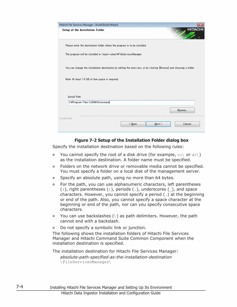
Figure 7-2 Setup of the Installation Folder dialog boxSpecify the installation destination based on the following rules:
¢ You cannot specify the root of a disk drive (for example, c:\ or d:\)as the installation destination. A folder name must be specified.
¢ Folders on the network drive or removable media cannot be specified.You must specify a folder on a local disk of the management server.
¢ Specify an absolute path, using no more than 64 bytes.
¢ For the path, you can use alphanumeric characters, left parentheses((), right parentheses ()), periods (.), underscores (_), and spacecharacters. However, you cannot specify a period (.) at the beginningor end of the path. Also, you cannot specify a space character at thebeginning or end of the path, nor can you specify consecutive spacecharacters.
¢ You can use backslashes (\) as path delimiters. However, the pathcannot end with a backslash.
¢ Do not specify a symbolic link or junction.The following shows the installation folders of Hitachi File ServicesManager and Hitachi Command Suite Common Component when theinstallation destination is specified.
The installation destination for Hitachi File Services Manager:absolute-path-specified-as-the-installation-destination\FileServicesManager\
7-4 Installing Hitachi File Services Manager and Setting Up Its EnvironmentHitachi Data Ingestor Installation and Configuration Guide

The installation destination for Hitachi Command Suite CommonComponent:
absolute-path-specified-as-the-installation-destination\Base\If any Hitachi Command Suite product has already been installed onthe computer on which you are installing Hitachi File ServicesManager, the installer will overwrite the existing version of HitachiCommand Suite Common Component instead of installing it in thespecified folder.
5. Specify the installation destination, and then click the Next button.The Specify the Storage Destination for Database Files of HitachiFile Services Manager dialog box appears.
Figure 7-3 Specify the Storage Destination for Database Files ofHitachi File Services Manager dialog box
Specify the folder for storing database files based on the following rules:
¢ Specify an absolute path, using no more than 90 bytes.
¢ For the path, you can use alphanumeric characters, left parentheses((), right parentheses ()), periods (.), underscores (_), and spacecharacters. However, you cannot specify a period (.) at the beginningor end of the path. Also, you cannot specify a space character at thebeginning or end of the path, nor can you specify consecutive spacecharacters.
¢ You can use backslashes (\) as path delimiters. However, the pathcannot end with a backslash.
Installing Hitachi File Services Manager and Setting Up Its Environment 7-5Hitachi Data Ingestor Installation and Configuration Guide

6. Specify the folder for storing database files, and then click the Nextbutton.The operation you perform after clicking the Next button differsdepending on whether Windows Firewall is installed.
If Windows Firewall is installed:The Registration into the Windows Firewall Exceptions Listdialog box appears. Check the information displayed in the dialog box,and then click the Next button. The Confirmation BeforeInstallation dialog box appears.
If Windows Firewall is not installed:The Confirmation Before Installation dialog box appears.
7. Make sure that the specified information is correct, and then click theInstall button.Installation starts and a series of dialog boxes indicating the processingstatus appear. If the installation is successful, the InstallationComplete dialog box appears.Note:
¢ Clicking the Install button automatically imports the SSL certificateinto the following keystore file:Hitachi-Command-Suite-Common-Component-installation-folder\jdk\jre\lib\security\jssecacertsThe default password is changeit. After installation, execute thefollowing command on the management server to change thepassword:
Hitachi-Command-Suite-Common-Component-installation-folder\bin\hcmdskeytool -storepasswd -keystore Hitachi-Command-Suite-Common-Component-installation-folder\jdk\jre\lib\security\jssecacerts -storepass current-changeit-password -new new-password
¢ If the password for the management server keystore file(jssecacerts) has been set, an error dialog box appears before theInstallation Complete dialog box is displayed. Check theinformation displayed in the dialog box, and then click the OK button.After the installation is complete, import the SSL certificate to themanagement server. For details on how to import the SSL certificateto the management server, see Importing the required SSL certificatefor communication between the node and management server onpage 7-98.
8. Click the Finish button to complete the installation.If the management server is in a non-cluster configuration, the HitachiCommand Suite Common Component services start and Hitachi FileServices Manager is ready for operation.If the management server is in a cluster configuration, continue the setuprequired to run the management server in a cluster configuration. Fordetails on how to install Hitachi File Services Manager on a managementserver in a cluster configuration, see Installing and uninstalling Hitachi
7-6 Installing Hitachi File Services Manager and Setting Up Its EnvironmentHitachi Data Ingestor Installation and Configuration Guide

File Services Manager (if the management server is running in a clusterconfiguration) on page 7-15.
Performing an upgrade or overwrite installation of Hitachi FileServices Manager
This section describes how to perform an upgrade or overwrite installation ofHitachi File Services Manager on the management server on which HitachiFile Services Manager has already been installed.
On the management server on which Hitachi File Services Manager has beeninstalled, you can update the version of Hitachi File Services Manager byinstalling a newer version as an upgrade installation. If you update the OSversion of the node on which Hitachi File Services Manager has beeninstalled, always update Hitachi File Services Manager to the latest version byperforming an upgrade installation.
In addition, if Hitachi File Services Manager configuration files have becomecorrupted due to a failure or a mistake by the system administrator, you canrestore the files by installing the same version of Hitachi File ServicesManager as an overwrite installation.
Note:You cannot perform an overwrite installation of Hitachi File ServicesManager whose version is older than the version of Hitachi File ServicesManager currently installed on the management server. If you want touse an older version of Hitachi File Services Manager, uninstall thecurrently installed Hitachi File Services Manager, and then install the olderversion as a new installation.
To perform an upgrade or overwrite installation of Hitachi FileServices Manager:
1. Insert the installation media for Hitachi File Services Manager.If you want to copy the contents of the installation media, you must copythem to a local disk of the management server. You cannot perform aninstallation by using data on the network drive.
2. Use Explorer to view the contents of the installation media, and thenexecute HFSMinst.exe.
The license agreement dialog box appears.
3. Read the terms, and then click the Yes button.The Welcome to the Installation of Hitachi File Services Manager(Upgrade) dialog box or the Welcome to the Installation of HitachiFile Services Manager (Overwrite) dialog box appears. The followingshows an example of the dialog box displayed when an overwriteinstallation is performed.
Installing Hitachi File Services Manager and Setting Up Its Environment 7-7Hitachi Data Ingestor Installation and Configuration Guide

Figure 7-4 Welcome to the Installation of Hitachi File ServicesManager (Overwrite) dialog box
Note:When you click the Next button, the installer stops the services of HitachiCommand Suite Common Component and other Hitachi Command Suiteproducts.
4. Check the information displayed in the dialog box, and then click theNext button.The Confirmation of the Setup Status of the Hitachi CommandSuite Common Component Database dialog box appears.This dialog box indicates how the installed Hitachi Command Suiteproducts have been configured.
5. Check the configuration, and then click the Next button.The Confirmation Before Installation dialog box is displayed.If the management server does not contain the Hitachi File ServicesManager database, the Specify the Storage Destination for DatabaseFiles of Hitachi File Services Manager dialog box appears before theConfirmation Before Installation dialog box. If this dialog boxappears, specify the database file storage folder, and then click the Nextbutton to continue installation.The following figure shows the Specify the Storage Destination forDatabase Files of Hitachi File Services Manager dialog box.
7-8 Installing Hitachi File Services Manager and Setting Up Its EnvironmentHitachi Data Ingestor Installation and Configuration Guide

Figure 7-5 Specify the Storage Destination for Database Files ofHitachi File Services Manager dialog box (for an installation other
than a new installation)Specify the folder for storing database files based on the following rules:
¢ Specify an absolute path, using no more than 90 bytes.
¢ For the path, you can use alphanumeric characters, left parentheses((), right parentheses ()), periods (.), underscores (_), and spacecharacters. However, you cannot specify a period (.) at the beginningor end of the path. Also, you cannot specify a space character at thebeginning or end of the path, nor can you specify consecutive spacecharacters.
¢ You can use backslashes (\) as path delimiters. However, the pathcannot end with a backslash.
6. Make sure that the specified information is correct, and then click theInstall button.Installation starts and a series of dialog boxes indicating the processingstatus appear. If the installation is successful, the InstallationComplete dialog box appears.If an upgrade or overwrite installation is performed, the existing HitachiFile Services Manager database is not initialized.If an upgrade installation is performed when a communication error existsbetween the management server and the node, the database cacheinformation on the management server and the information on the nodemight not match. If a mismatch occurs, eliminate the communicationerror, and then perform refresh processing.
Installing Hitachi File Services Manager and Setting Up Its Environment 7-9Hitachi Data Ingestor Installation and Configuration Guide

Note:If the password for the management server keystore file(jssecacerts) has been set, an error dialog box appears before theInstallation Complete dialog box is displayed. Check theinformation displayed in the dialog box, and then click the OK button.After the installation is complete, import the SSL certificate to themanagement server. For details on how to import the SSL certificateto the management server, see Importing the required SSL certificatefor communication between the node and management server onpage 7-98.
7. Click the Finish button to complete the installation.If the management server is in a non-cluster configuration, the HitachiCommand Suite Common Component services start and Hitachi FileServices Manager is ready for operation.If the management server is in a cluster configuration, continue the setuprequired to run the management server in a cluster configuration. Fordetails on how to install Hitachi File Services Manager on a managementserver in a cluster configuration, see Installing and uninstalling HitachiFile Services Manager (if the management server is running in a clusterconfiguration) on page 7-15.
Uninstalling Hitachi File Services ManagerThis section describes how to uninstall Hitachi File Services Manager.
Removing Hitachi File Services Manager prerequisites
The following describes the tasks that you need to carry out beforeuninstalling Hitachi File Services Manager.
• Log on to Windows as an Administrator or a member of theAdministrators group.
• Stop Hitachi File Services Manager and Hitachi Command Suite productservices.
• Back up Hitachi File Services Manager and the Hitachi Command Suiteproduct databases.
• If a security monitoring program has been installed, either stop it orchange its settings so that it does not hamper uninstallation of Hitachi FileServices Manager.
• If a virus detecting program has been installed, we recommend stoppingit before you uninstall Hitachi File Services Manager.If an antivirus program is running during Hitachi File Services Manageruninstallation, the uninstallation might slow down, fail, or be performedincorrectly.
• If a process monitoring program is installed, stop it or change its settingsso that the services and processes of Hitachi File Services Manager andHitachi Command Suite Common Component are not monitored.
7-10 Installing Hitachi File Services Manager and Setting Up Its EnvironmentHitachi Data Ingestor Installation and Configuration Guide

If a process monitoring program starts or stops the services or processesof Hitachi File Services Manager and Hitachi Command Suite CommonComponent during uninstallation of Hitachi File Services Manager, theuninstallation might fail.
• Close all windows used for operating Windows services.
Performing an uninstallation
To uninstall Hitachi File Services Manager:
1. Open the Uninstallation of Hitachi File Services Manager dialog box.You can use either of the following methods to open this dialog box:
¢ If you are using Windows 7 or an earlier Windows version, chooseStart, Programs, Hitachi Command Suite, File ServicesManager, and then Uninstall - HFSM.If you are using Windows 8 or Windows Server 2012, select Uninstall- HFSM from the application list in the Start screen.
¢ From the Windows Programs and Features, select Hitachi FileServices Manager and then click the Uninstall.
The Uninstallation of Hitachi File Services Manager dialog boxappears.
Figure 7-6 Uninstallation of Hitachi File Services Manager dialogbox
2. Check the information displayed in the dialog box, and then click theNext button.The Confirmation of the Setup Status of the Hitachi CommandSuite Common Component Database dialog box is displayed.
Installing Hitachi File Services Manager and Setting Up Its Environment 7-11Hitachi Data Ingestor Installation and Configuration Guide

This dialog box indicates whether the Hitachi Command Suite productshave been installed on the management server in a non-clusterconfiguration, or on the executing or standby node of the managementserver in a cluster configuration.
3. Check the setup status, and then click the Next button.The Confirmation Before Uninstallation dialog box appears.
4. Make sure that Hitachi File Services Manager version and installationdestination displayed in the dialog box are correct, and then click theUninstall button.Uninstallation starts and a series of dialog boxes indicating the processingstatus appear. If the uninstallation is successful, the UninstallationComplete dialog box appears.
5. Click the Finish button to complete the uninstallation of Hitachi FileServices Manager.
Prerequisites for installing Hitachi File Services ManagerCheck the following before installing Hitachi File Services Manager.
Other products installed on the computer on which you will install Hitachi FileServices Manager:
Make sure that the versions of Hitachi Command Suite products are 4.0or later. Also make sure that a large configuration does not includeTuning Manager.
The environment of the computer on which you will install Hitachi FileServices Manager:
¢ Make sure that the computer meets the requirements for Hitachi FileServices Manager.For details on the requirements, see Requirements for a managementserver on page 3-5.
¢ If you are performing a new installation of Hitachi File ServicesManager, make sure that the target disk drive has sufficient freespace for installing the software.The following table lists the components to be installed and theamount of free space required to install each component.
Table 7-1 Components to be installed and free space required forinstallation
Component Required free space
Hitachi File Services Manager At least 1.5 GB
Hitachi File Services Manager database files At least 200 MB
The Hitachi File Services Manager and Hitachi File Services Managerdatabase files can be installed on separate disk drives.
¢ Execute the command netstat -a from a command prompt to checkwhether ports 23015 to 23018, port 23032, and ports 45001 to 49000
7-12 Installing Hitachi File Services Manager and Setting Up Its EnvironmentHitachi Data Ingestor Installation and Configuration Guide

are used by only Hitachi File Services Manager (if it has beeninstalled) and Hitachi Command Suite products.If products other than Hitachi File Services Manager and HitachiCommand Suite products are using ports 23015 to 23018 and port23032, change the port number settings either for those products orfor Hitachi File Services Manager. For details on how to change theport number for Hitachi File Services Manager, see Changing the portnumbers used by Hitachi Command Suite Common Component onpage 7-89.If port numbers 23015 to 23018 and port 23032 have been changedby Hitachi Command Suite products, you do not need to reset the portnumbers.If products other than Hitachi File Services Manager and HitachiCommand Suite products are using ports 45001 to 49000, change theport number settings in the products that are using these ports. InHitachi File Services Manager, port numbers 45001 to 49000 cannotbe changed.
Tasks that you need to carry out before installing or upgrading Hitachi FileServices Manager:
¢ Log on to Windows as an Administrator or a member of theAdministrators group.
¢ Stop the services of all Hitachi Command Suite products# that arerunning on the computer on which you are installing Hitachi FileServices Manager.If you install Hitachi File Services Manager without stopping theservices, the services of Hitachi Command Suite Common Componentand other Hitachi Command Suite products will be stopped during theinstallation. If the installer cannot stop the services, the installationwill be canceled.#Executing the hcmdssrv /stop command stops all of the HitachiCommand Suite product services, except the Hitachi Tuning Manager -Agent for SAN Switch services when Hitachi Tuning Manager - Agentfor SAN Switch is installed. In this case, note that you have to stopthe Hitachi Tuning Manager - Agent for SAN Switch services beforestopping the Hitachi Tuning Manager services. For details on how tostop the Hitachi Tuning Manager - Agent for SAN Switch services, seethe manual for Hitachi Tuning Manager - Agent for SAN Switch.
¢ If Hitachi NAS Manager is installed, uninstall it, and then install HitachiFile Services Manager.
¢ If Hitachi File Services Manager or Hitachi Command Suite productshave been installed, back up their databases.
¢ If any Hitachi Command Suite product has been installed, make surethat HiRDB/EmbeddedEdition _HD0 is running.
The Hitachi Command Suite products require that this service alwaysbe running. In the Windows Services window, check the list ofservices to make sure that it is running. If it has stopped, start it.
Installing Hitachi File Services Manager and Setting Up Its Environment 7-13Hitachi Data Ingestor Installation and Configuration Guide

¢ If a security monitoring program has been installed, either stop it orchange its settings so that it does not hamper installation of HitachiFile Services Manager.
¢ If a virus detecting program has been installed, we recommendstopping it before you install Hitachi File Services Manager.If an antivirus program is running during Hitachi File ServicesManager installation, the installation might slow down, fail, or beperformed incorrectly.
¢ If a process monitoring program is installed, stop it or change itssettings so that the services and processes of Hitachi File ServicesManager and Hitachi Command Suite Common Component are notmonitored.If a process monitoring program starts or stops the services orprocesses of Hitachi File Services Manager and Hitachi CommandSuite Common Component during installation of Hitachi File ServicesManager, the installation might fail.
¢ Adjust the time on the computer on which Hitachi File ServicesManager is to be installed.Do not adjust the time on the management server after Hitachi FileServices Manager has been installed. If you change the time whileHitachi File Services Manager and Hitachi Command Suite CommonComponent are running, Hitachi File Services Manager might not beable to operate correctly. For details on how to adjust the time on themanagement server after Hitachi File Services Manager has beeninstalled, see Adjusting the management server time on page 7-129.
¢ Close all windows used for operating Windows services.
¢ When the OS of the computer on which you will install Hitachi FileServices Manager is a version of Windows that includes the DataExecution Prevention (DEP) function (such as Windows Server 2003SP1), if DEP is enabled, insert the installation media for Hitachi FileServices Manager and disable DEP for the file HFSMinst.exe.
Notes on using Hitachi File Services Manager by logging in from the DeviceManager GUI
When linking with Device Manager, Hitachi File Services Manager can beused by logging in from the Device Manager GUI. Required settings varydepending on the installation destination of Hitachi File Services Managerand Device Manager. Note the following when using Hitachi File ServicesManager by logging in from the Device Manager GUI:
If both Hitachi File Services Manager and Device Manager are installed onthe same management server:
- Start Device Manager after Hitachi File Services Manager has beeninstalled. For details on how to start Device Manager, see theapplicable Device Manager manual. If you install Hitachi File ServicesManager on the management server on which Device Manager version8.0 or later has already been installed, specify settings so that HitachiFile Services Manager connects to Device Manager to manage user
7-14 Installing Hitachi File Services Manager and Setting Up Its EnvironmentHitachi Data Ingestor Installation and Configuration Guide
accounts. For details on the procedure, see Connecting to DeviceManager to manage user accounts on page 7-82.- If Device Manager cannot be started after installation of Hitachi FileServices Manager, there might be a port conflict with other products.Change the port numbers used by Device Manager, and then startDevice Manager. For details on how to change the port numbers usedby Device Manager, see the applicable Device Manager manual.- For the user account used for authentication by Device Manager, setthe Admin (application management) permission for Hitachi FileServices Manager.- If you uninstall Device Manager version 8.0 or later, you must alsouninstall Hitachi File Services Manager.
If Hitachi File Services Manager and Device Manager are installed onseparate computers:
- Specify settings so that Hitachi File Services Manager connects toDevice Manager to manage user accounts. For details on theprocedure, see Connecting to Device Manager to manage useraccounts on page 7-82.- For the user account used for authentication by Device Manager, setthe Admin (application management) permission for Hitachi FileServices Manager.
Installing and uninstalling Hitachi File Services Manager (ifthe management server is running in a clusterconfiguration)
This section describes how to install and uninstall Hitachi File ServicesManager if the management server is running in a cluster configuration. Thissubsection describes Windows Server 2003. If you are using Windows Server2008 or Windows Server 2012, replace the term Microsoft Cluster Servicewith Microsoft Failover Cluster, and replace the term Cluster Administratorwith Failover Cluster Management as you read through the procedures. Besure to also refer to any related Failover Cluster Management documentationin order to note the differences in the settings.
Before you install Hitachi File Services Manager on a management server in acluster configuration, make sure that the following conditions are satisfied:
• The computer on which Hitachi File Services Manager is to be installedsatisfies the requirements of the management server (Table 3-2Requirements for a management server on page 3-5).
• Software required for cluster configurations has been installed on thecomputer on which Hitachi File Services Manager is to be installed (Table3-5 Applicable OSs and required cluster software for operatingmanagement servers in a cluster configuration on page 3-9).
• The same version of Hitachi File Services Manager is to be installed on theexecuting node and on the standby node.
Installing Hitachi File Services Manager and Setting Up Its Environment 7-15Hitachi Data Ingestor Installation and Configuration Guide

Performing a new installation of Hitachi File Services Manager (if themanagement server is running in a cluster configuration)
This section describes how to perform a new installation of Hitachi FileServices Manager on a management server in a cluster configuration.
Changing the management server to a cluster configuration
If the cluster management IP address and shared disk are not set up inCluster Administrator of Microsoft Cluster Service, perform the following:
1. From the Windows Start menu, choose Settings, Control Panel,Administrative Tools, and then Cluster Administrator to displayCluster Administrator.
2. In the Resource type drop-down list, select IP address, and thenregister the cluster management IP address for the group.
3. In the Resource type drop-down list, select Network Name, and thenregister the logical host name for the group.
4. In the Resource type drop-down list, select Physical Disk, and thenregister the shared disk for the group.
5. In Cluster Administrator, place the group online.
Installations in cluster environments prerequisites
Before you perform a new installation of Hitachi File Services Manager on amanagement server in a cluster configuration, check the following:
• For the executing and standby nodes of the management server and forthe cluster management IP address, make sure that the IP address canbe resolved from the host name.
• Make sure that Hitachi File Services Manager will not be accessed whileyou are configuring a cluster.
• Perform installation on the executing node of the management serverbefore performing installation on the standby node.
Performing a new installation on the executing node of the management server
To perform a new installation of Hitachi File Services Manager on theexecuting node and configure the cluster:
1. Perform a new installation of Hitachi File Services Manager on theexecuting node.For details on how to perform a new installation of Hitachi File ServicesManager, see Performing a new installation of Hitachi File ServicesManager on page 7-2. When installing Hitachi File Services Manager, usethe default storage locations for the databases used by Hitachi CommandSuite Common Component and Hitachi File Services Manager.
2. Use a text editor to create a cluster-configuration file.Specify the following items in the cluster-configuration file:
¢ mode
7-16 Installing Hitachi File Services Manager and Setting Up Its EnvironmentHitachi Data Ingestor Installation and Configuration Guide

Specify online.
¢ virtualhostSpecify the logical host name.
¢ onlinehostSpecify the host name of the executing node.
¢ standbyhostSpecify the host name of the standby node.
An IP address cannot be specified for virtualhost, onlinehost, orstandbyhost.
The following shows an example of the cluster-configuration file:
mode = onlinevirtualhost = hicommand_clusteronlinehost = hicommand_1standbyhost = hicommand_2
3. Save the cluster-configuration file as cluster.conf in the followingfolder:Hitachi-Command-Suite-Common-Component-installation-folder\conf\
4. Stop the services of Tuning Manager that connects to Device Manager onthe management server.This step is necessary if Tuning Manager and Device Manager have beeninstalled on different computers. Stop the services on the computer onwhich Tuning Manager has been installed. For details on how to stop theservices of Tuning Manager, see the relevant manuals for the installedversion of Tuning Manager.
5. Make sure that you are ready to stop Hitachi File Services Manager andHitachi Command Suite Common Component.Hitachi File Services Manager and Hitachi Command Suite CommonComponent automatically stop when the command in the next step isexecuted.
6. Execute the following command to back up the database.
Hitachi-Command-Suite-Common-Component-installation-folder\bin\hcmdsbackups /dir backup-target-folder /auto
In backup-target-folder, specify the absolute path of a folder on a localdisk. If you specify an existing folder, make sure that the folder is empty.In the path you specify, you can use alphanumeric characters, spaces,exclamation marks (!), hash marks (#), left parentheses ((), rightparentheses ()), plus signs (+), hyphens (-), periods (.), equal signs (=),at marks (@), left square brackets ([), right square brackets (]), carets(^), underscores (_), left curly brackets ({), right curly brackets (}), andtildes (~). In addition to these characters, you can use forward slashes(/), colons (:), and backslashes (\) as path delimiters.
When you execute the hcmdsbackups command, a folder nameddatabase will be created in the folder for storing backup files (backup-
Installing Hitachi File Services Manager and Setting Up Its Environment 7-17Hitachi Data Ingestor Installation and Configuration Guide
target-folder), and the database backup file will be stored with the namebackup.hdb.
If Tuning Manager and Device Manager have been installed on differentcomputers, the services of Tuning Manager will not automatically start orstop even if the /auto option is specified.
7. Execute the following command to migrate the database to the shareddisk:
Hitachi-Command-Suite-Common-Component-installation-folder\bin\hcmdsdbclustersetup /createcluster /databasepath database-re-creation-destination-folder /exportpath data-storage-destination-folder /auto
Specify the command arguments based on the following rules:
¢ For database-re-creation-destination-folder, specify an absolute paththat does not exceed 92 bytes. For data-storage-destination-folder,specify an absolute path that does not exceed 85 bytes.
¢ For database-re-creation-destination-folder, specify a location on theshared disk.
¢ For data-storage-destination-folder, specify a location on the shareddisk.
¢ If you specify an existing folder as data-storage-destination-folder,make sure that the folder is empty.
¢ For database-re-creation-destination-folder and data-storage-destination-folder, the following characters can be used: alphanumericcharacters, left parentheses ((), right parentheses ()), periods (.),underscores (_), and spaces. However, you cannot specify a period(.) at the beginning or end of the path. Also, you cannot specify aspace character at the beginning or end of the path, nor can youspecify consecutive space characters.
¢ For database-re-creation-destination-folder and data-storage-destination-folder, backslashes (\) can be used as path delimiters.However, the path cannot end with a backslash.
The space required for database-re-creation-destination-folder can becalculated as follows:required-space = 2.1 GB + database-capacity-for-other-Hitachi-Command-Suite-productsIf the hcmdsdbclustersetup command execution fails because there isnot enough space for database-re-creation-destination-folder, increasethe space for the folder, and then re-execute the command.Do not disconnect the shared disk from the executing node until thecommand execution terminates normally.If the command execution terminated abnormally and then you restartthe server, the connection target of the shared disk might be changed tothe standby node.When this command is executed, the port number used by HiRDB is resetto the default (23032).
7-18 Installing Hitachi File Services Manager and Setting Up Its EnvironmentHitachi Data Ingestor Installation and Configuration Guide
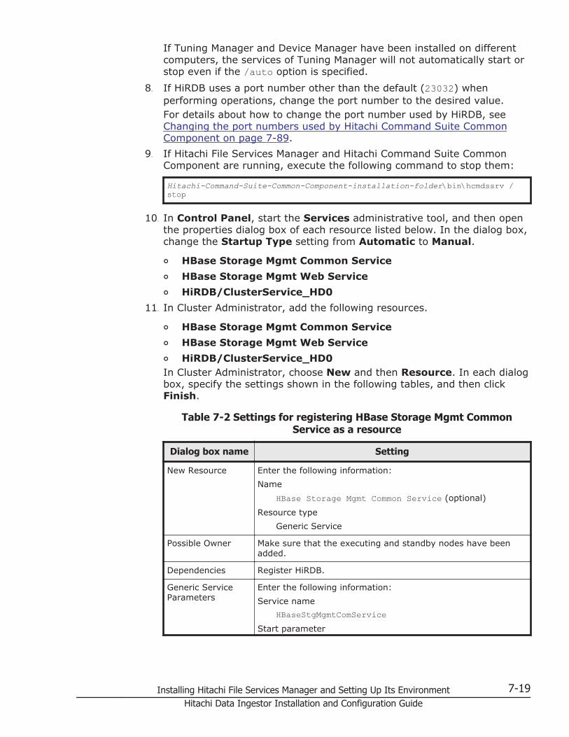
If Tuning Manager and Device Manager have been installed on differentcomputers, the services of Tuning Manager will not automatically start orstop even if the /auto option is specified.
8. If HiRDB uses a port number other than the default (23032) whenperforming operations, change the port number to the desired value.For details about how to change the port number used by HiRDB, seeChanging the port numbers used by Hitachi Command Suite CommonComponent on page 7-89.
9. If Hitachi File Services Manager and Hitachi Command Suite CommonComponent are running, execute the following command to stop them:
Hitachi-Command-Suite-Common-Component-installation-folder\bin\hcmdssrv /stop
10. In Control Panel, start the Services administrative tool, and then openthe properties dialog box of each resource listed below. In the dialog box,change the Startup Type setting from Automatic to Manual.
¢ HBase Storage Mgmt Common Service
¢ HBase Storage Mgmt Web Service
¢ HiRDB/ClusterService_HD0
11. In Cluster Administrator, add the following resources.
¢ HBase Storage Mgmt Common Service
¢ HBase Storage Mgmt Web Service
¢ HiRDB/ClusterService_HD0In Cluster Administrator, choose New and then Resource. In each dialogbox, specify the settings shown in the following tables, and then clickFinish.
Table 7-2 Settings for registering HBase Storage Mgmt CommonService as a resource
Dialog box name Setting
New Resource Enter the following information:
Name
HBase Storage Mgmt Common Service (optional)
Resource type
Generic Service
Possible Owner Make sure that the executing and standby nodes have beenadded.
Dependencies Register HiRDB.
Generic ServiceParameters
Enter the following information:
Service name
HBaseStgMgmtComServiceStart parameter
Installing Hitachi File Services Manager and Setting Up Its Environment 7-19Hitachi Data Ingestor Installation and Configuration Guide

Dialog box name Setting
None
Registry Replication Specify nothing.
Table 7-3 Settings for registering HBase Storage Mgmt Web Service asa resource
Dialog box name Setting
New Resource Enter the following information:
Name
HBase Storage Mgmt Web Service (optional)
Resource type
Generic Service
Possible Owner Make sure that the executing and standby nodes have beenadded.
Dependencies Register HBaseStgMgmtComService.
Generic ServiceParameters
Enter the following information:
Service name
HBaseStgMgmtWebServiceStart parameter
None
Registry Replication Specify nothing.
Table 7-4 Settings for registering HiRDB as a resource
Dialog box name Setting
New Resource Enter the following information:
Name
HiRDB (optional)
Resource type
Generic Service
Possible Owner Make sure that the executing and standby nodes have beenadded.
Dependencies Register the shared disk drive and network name.
Generic ServiceParameters
Enter the following information:
Service name
HiRDBClusterService_HD0Start parameter
None
Registry Replication Specify nothing.
7-20 Installing Hitachi File Services Manager and Setting Up Its EnvironmentHitachi Data Ingestor Installation and Configuration Guide
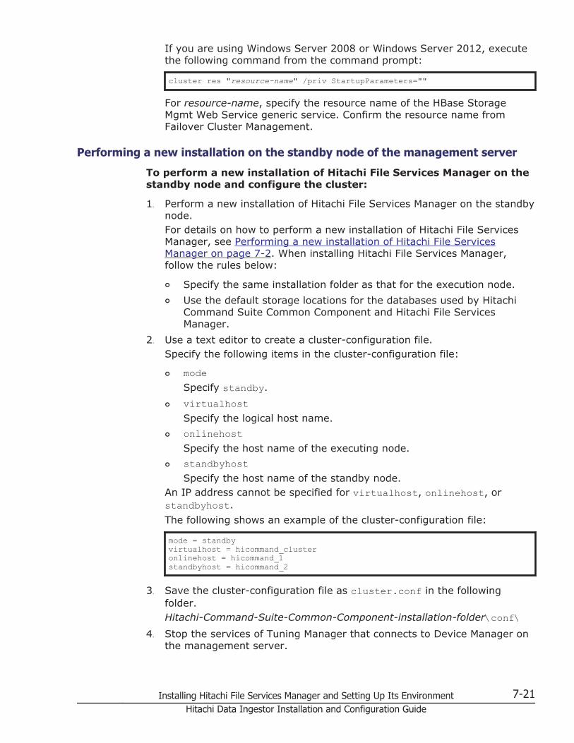
If you are using Windows Server 2008 or Windows Server 2012, executethe following command from the command prompt:
cluster res "resource-name" /priv StartupParameters=""
For resource-name, specify the resource name of the HBase StorageMgmt Web Service generic service. Confirm the resource name fromFailover Cluster Management.
Performing a new installation on the standby node of the management server
To perform a new installation of Hitachi File Services Manager on thestandby node and configure the cluster:
1. Perform a new installation of Hitachi File Services Manager on the standbynode.For details on how to perform a new installation of Hitachi File ServicesManager, see Performing a new installation of Hitachi File ServicesManager on page 7-2. When installing Hitachi File Services Manager,follow the rules below:
¢ Specify the same installation folder as that for the execution node.
¢ Use the default storage locations for the databases used by HitachiCommand Suite Common Component and Hitachi File ServicesManager.
2. Use a text editor to create a cluster-configuration file.Specify the following items in the cluster-configuration file:
¢ modeSpecify standby.
¢ virtualhostSpecify the logical host name.
¢ onlinehostSpecify the host name of the executing node.
¢ standbyhostSpecify the host name of the standby node.
An IP address cannot be specified for virtualhost, onlinehost, orstandbyhost.
The following shows an example of the cluster-configuration file:
mode = standbyvirtualhost = hicommand_clusteronlinehost = hicommand_1standbyhost = hicommand_2
3. Save the cluster-configuration file as cluster.conf in the followingfolder.Hitachi-Command-Suite-Common-Component-installation-folder\conf\
4. Stop the services of Tuning Manager that connects to Device Manager onthe management server.
Installing Hitachi File Services Manager and Setting Up Its Environment 7-21Hitachi Data Ingestor Installation and Configuration Guide

This step is necessary if Tuning Manager and Device Manager have beeninstalled on different computers. Stop the services on the computer onwhich Tuning Manager has been installed. For details on how to stop theservices of Tuning Manager, see the relevant manuals for the installedversion of Tuning Manager.
5. Make sure that you are ready to stop Hitachi File Services Manager andHitachi Command Suite Common Component.Hitachi File Services Manager and Hitachi Command Suite CommonComponent automatically stop when the command in the next step isexecuted.
6. Execute the following command to specify that the database on theshared disk be used:
Hitachi-Command-Suite-Common-Component-installation-folder\bin\hcmdsdbclustersetup /createcluster /databasepath database-re-creation-destination-folder /exportpath data-storage-destination-folder /auto
Specify the command arguments based on the following rules:
¢ For database-re-creation-destination-folder, specify the same folderas the executing node.
¢ For data-storage-destination-folder, specify an absolute path thatdoes not exceed 85 bytes.
¢ For data-storage-destination-folder, specify a location on the localdisk.
¢ If you specify an existing folder as data-storage-destination-folder,make sure that the folder is empty.
¢ For data-storage-destination-folder, the following characters can beused: alphanumeric characters, left parentheses ((), rightparentheses ()), periods (.), underscores (_), and spaces. However,you cannot specify a period (.) at the beginning or end of the path.Also, you cannot specify a space character at the beginning or end ofthe path, nor can you specify consecutive space characters.
¢ For data-storage-destination-folder, backslashes (\) can be used aspath delimiters. However, the path cannot end with a backslash.
Do not disconnect the shared disk from the executing node until thehcmdsdbclustersetup command execution terminates normally.
If the command execution terminated abnormally, do not restart theserver.When this command is executed, the port number used by HiRDB is resetto the default (23032).
If Tuning Manager and Device Manager have been installed on differentcomputers, the services of Tuning Manager will not automatically start orstop even if the /auto option is specified.
7. If HiRDB uses a port number other than the default (23032) whenperforming operations, change the port number to the desired value.For details about how to change the port number used by HiRDB, seeChanging the port numbers used by Hitachi Command Suite CommonComponent on page 7-89.
7-22 Installing Hitachi File Services Manager and Setting Up Its EnvironmentHitachi Data Ingestor Installation and Configuration Guide

8. If Hitachi File Services Manager and Hitachi Command Suite CommonComponent are running, execute the following command to stop them:
Hitachi-Command-Suite-Common-Component-installation-folder\bin\hcmdssrv /stop
9. In Control Panel, start the Services administrative tool, and then openthe properties dialog box of each resource listed below. In the dialog box,change the Startup Type setting from Automatic to Manual.
¢ HBase Storage Mgmt Common Service
¢ HBase Storage Mgmt Web Service
¢ HiRDB/ClusterService_HD0
10. In Cluster Administrator, place the group online.
Performing an upgrade or overwrite installation of Hitachi FileServices Manager (if the management server is running in a clusterconfiguration)
This section describes how to perform an upgrade or overwrite installation ofHitachi File Services Manager if the management server is running in acluster configuration.
Perform installation on the executing node of the management server beforeperforming installation on the standby node.
Upgrade or overwrite installation on the executing node of the managementserver
To perform an upgrade or overwrite installation of Hitachi File ServicesManager on the executing node and set up Hitachi File Services Manager for acluster system:
1. From the Windows Start menu, choose Settings, Control Panel,Administrative Tools, and then Cluster Administrator to displayCluster Administrator.
2. In Cluster Administrator, place the following resources offline.
¢ HBase Storage Mgmt Common Service
¢ HBase Storage Mgmt Web Service
3. Execute the following command to stop Hitachi File Services Manager andHitachi Command Suite Common Component:
Hitachi-Command-Suite-Common-Component-installation-folder\bin\hcmdssrv /stop
4. In Cluster Administrator, place HiRDB/ClusterService_HD0 offline.
5. Prevent the resources from restarting. In Cluster Administrator, open theproperties dialog box of each resource listed below. In the dialog box,choose the Advanced tab, select Do not restart, and then click the OKbutton.
Installing Hitachi File Services Manager and Setting Up Its Environment 7-23Hitachi Data Ingestor Installation and Configuration Guide
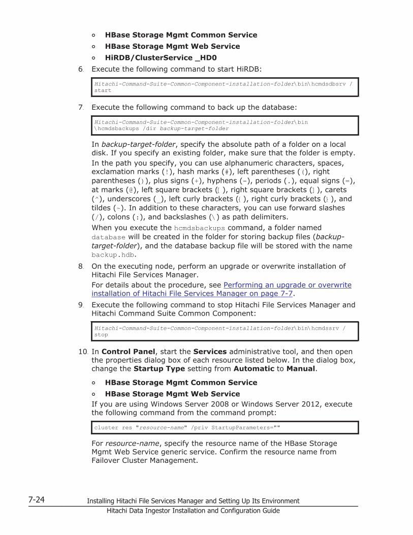
¢ HBase Storage Mgmt Common Service
¢ HBase Storage Mgmt Web Service
¢ HiRDB/ClusterService _HD0
6. Execute the following command to start HiRDB:
Hitachi-Command-Suite-Common-Component-installation-folder\bin\hcmdsdbsrv /start
7. Execute the following command to back up the database:
Hitachi-Command-Suite-Common-Component-installation-folder\bin\hcmdsbackups /dir backup-target-folder
In backup-target-folder, specify the absolute path of a folder on a localdisk. If you specify an existing folder, make sure that the folder is empty.In the path you specify, you can use alphanumeric characters, spaces,exclamation marks (!), hash marks (#), left parentheses ((), rightparentheses ()), plus signs (+), hyphens (-), periods (.), equal signs (=),at marks (@), left square brackets ([), right square brackets (]), carets(^), underscores (_), left curly brackets ({), right curly brackets (}), andtildes (~). In addition to these characters, you can use forward slashes(/), colons (:), and backslashes (\) as path delimiters.
When you execute the hcmdsbackups command, a folder nameddatabase will be created in the folder for storing backup files (backup-target-folder), and the database backup file will be stored with the namebackup.hdb.
8. On the executing node, perform an upgrade or overwrite installation ofHitachi File Services Manager.For details about the procedure, see Performing an upgrade or overwriteinstallation of Hitachi File Services Manager on page 7-7.
9. Execute the following command to stop Hitachi File Services Manager andHitachi Command Suite Common Component:
Hitachi-Command-Suite-Common-Component-installation-folder\bin\hcmdssrv /stop
10. In Control Panel, start the Services administrative tool, and then openthe properties dialog box of each resource listed below. In the dialog box,change the Startup Type setting from Automatic to Manual.
¢ HBase Storage Mgmt Common Service
¢ HBase Storage Mgmt Web ServiceIf you are using Windows Server 2008 or Windows Server 2012, executethe following command from the command prompt:
cluster res "resource-name" /priv StartupParameters=""
For resource-name, specify the resource name of the HBase StorageMgmt Web Service generic service. Confirm the resource name fromFailover Cluster Management.
7-24 Installing Hitachi File Services Manager and Setting Up Its EnvironmentHitachi Data Ingestor Installation and Configuration Guide

11. In Cluster Administrator, switch the group in which Hitachi File ServicesManager resources are registered to the standby node.To switch to the standby node, right-click the group in which theresources used by Hitachi File Services Manager are registered, and thenselect Move Group.
Upgrade or overwrite installation on the standby node of the managementserver
To perform an upgrade or overwrite installation of Hitachi File ServicesManager on the standby node and set up Hitachi File Services Manager for acluster system:
1. Execute the following command to stop Hitachi File Services Manager andHitachi Command Suite Common Component:
Hitachi-Command-Suite-Common-Component-installation-folder\bin\hcmdssrv /stop
2. Execute the following command to start HiRDB:
Hitachi-Command-Suite-Common-Component-installation-folder\bin\hcmdsdbsrv /start
3. Execute the following command to back up the database:
Hitachi-Command-Suite-Common-Component-installation-folder\bin\hcmdsbackups /dir backup-target-folder
In backup-target-folder, specify the absolute path of a folder on a localdisk. If you specify an existing folder, make sure that the folder is empty.In the path you specify, you can use alphanumeric characters, spaces,exclamation marks (!), hash marks (#), left parentheses ((), rightparentheses ()), plus signs (+), hyphens (-), periods (.), equal signs (=),at marks (@), left square brackets ([), right square brackets (]), carets(^), underscores (_), left curly brackets ({), right curly brackets (}), andtildes (~). In addition to these characters, you can use forward slashes(/), colons (:), and backslashes (\) as path delimiters.
When you execute the hcmdsbackups command, a folder nameddatabase will be created in the folder for storing backup files (backup-target-folder), and the database backup file will be stored with the namebackup.hdb.
4. On the standby node, perform an upgrade or overwrite installation ofHitachi File Services Manager.For details about the procedure, see Performing an upgrade or overwriteinstallation of Hitachi File Services Manager on page 7-7.
5. Execute the following command to stop Hitachi File Services Manager andHitachi Command Suite Common Component:
Hitachi-Command-Suite-Common-Component-installation-folder\bin\hcmdssrv /stop
Installing Hitachi File Services Manager and Setting Up Its Environment 7-25Hitachi Data Ingestor Installation and Configuration Guide

6. In Control Panel, start the Services administrative tool, and then openthe properties dialog box of each resource listed below. In the dialog box,change the Startup Type setting from Automatic to Manual.
¢ HBase Storage Mgmt Common Service
¢ HBase Storage Mgmt Web Service
7. In Cluster Administrator, switch the group in which Hitachi File ServicesManager resources are registered to the executing node.To switch to the executing node, right-click the group in which theresources used by Hitachi File Services Manager are registered, and thenselect Move Group.
8. In Cluster Administrator, open the properties dialog box of each resourcelisted below. In the dialog box, choose the Advanced tab, select Do notrestart, and then click the OK button.
¢ HBase Storage Mgmt Common Service
¢ HBase Storage Mgmt Web Service
¢ HiRDB/ClusterService_HD0
9. In Cluster Administrator, place online the group in which the resources forHitachi File Services Manager have been registered.
Performing a new installation, upgrade installation, or overwriteinstallation of Hitachi File Services Manager (when Hitachi CommandSuite products are running in a cluster configuration)
This section describes how to temporarily cancel the cluster configuration toinstall Hitachi File Services Manager when Hitachi Command Suite productsare running in the cluster configuration.
1. Remove the resources for Hitachi Command Suite products and clustergroups from the targets of cluster management.To do this, perform the following operations:
¢ In Cluster Administrator, place the target resources offline.
¢ In Cluster Administrator, prevent the target resources from restarting.Open the properties dialog box of each resource. In the dialog box,choose the Advanced tab, select Do not restart, and then click theOK button. If there are multiple target resources, repeat this step asnecessary.
2. On both the executing and standby nodes, stop the services of theHiCommand products whose version is earlier than 5.7.This step is necessary only if HiCommand products whose version isearlier than 5.7 are installed. For details on how to stop the service of aHiCommand product, see the documentation for that product.
3. Execute the following command on both the executing and standby nodesto stop Hitachi File Services Manager and Hitachi Command SuiteCommon Component:
7-26 Installing Hitachi File Services Manager and Setting Up Its EnvironmentHitachi Data Ingestor Installation and Configuration Guide
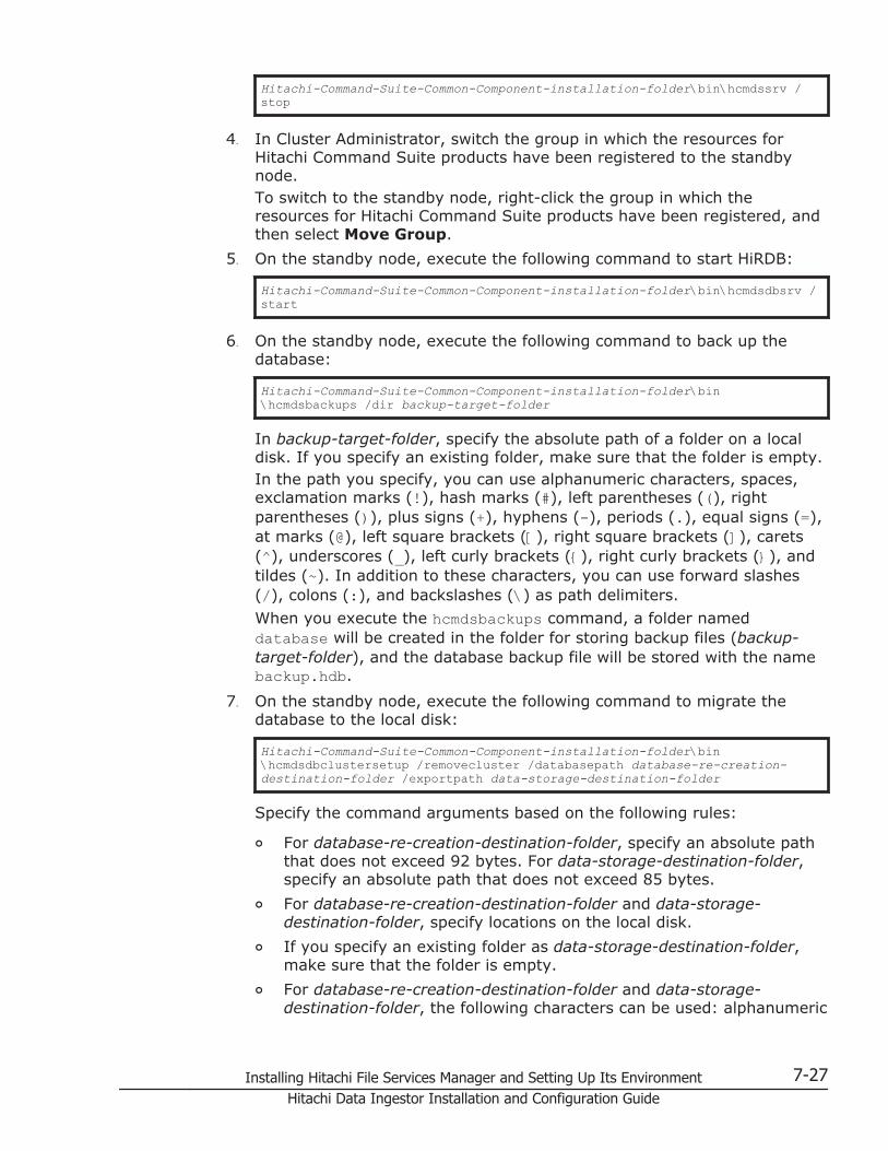
Hitachi-Command-Suite-Common-Component-installation-folder\bin\hcmdssrv /stop
4. In Cluster Administrator, switch the group in which the resources forHitachi Command Suite products have been registered to the standbynode.To switch to the standby node, right-click the group in which theresources for Hitachi Command Suite products have been registered, andthen select Move Group.
5. On the standby node, execute the following command to start HiRDB:
Hitachi-Command-Suite-Common-Component-installation-folder\bin\hcmdsdbsrv /start
6. On the standby node, execute the following command to back up thedatabase:
Hitachi-Command-Suite-Common-Component-installation-folder\bin\hcmdsbackups /dir backup-target-folder
In backup-target-folder, specify the absolute path of a folder on a localdisk. If you specify an existing folder, make sure that the folder is empty.In the path you specify, you can use alphanumeric characters, spaces,exclamation marks (!), hash marks (#), left parentheses ((), rightparentheses ()), plus signs (+), hyphens (-), periods (.), equal signs (=),at marks (@), left square brackets ([), right square brackets (]), carets(^), underscores (_), left curly brackets ({), right curly brackets (}), andtildes (~). In addition to these characters, you can use forward slashes(/), colons (:), and backslashes (\) as path delimiters.
When you execute the hcmdsbackups command, a folder nameddatabase will be created in the folder for storing backup files (backup-target-folder), and the database backup file will be stored with the namebackup.hdb.
7. On the standby node, execute the following command to migrate thedatabase to the local disk:
Hitachi-Command-Suite-Common-Component-installation-folder\bin\hcmdsdbclustersetup /removecluster /databasepath database-re-creation-destination-folder /exportpath data-storage-destination-folder
Specify the command arguments based on the following rules:
¢ For database-re-creation-destination-folder, specify an absolute paththat does not exceed 92 bytes. For data-storage-destination-folder,specify an absolute path that does not exceed 85 bytes.
¢ For database-re-creation-destination-folder and data-storage-destination-folder, specify locations on the local disk.
¢ If you specify an existing folder as data-storage-destination-folder,make sure that the folder is empty.
¢ For database-re-creation-destination-folder and data-storage-destination-folder, the following characters can be used: alphanumeric
Installing Hitachi File Services Manager and Setting Up Its Environment 7-27Hitachi Data Ingestor Installation and Configuration Guide
characters, left parentheses ((), right parentheses ()), periods (.),underscores (_), and spaces. However, you cannot specify a period(.) at the beginning or end of the path. Also, you cannot specify aspace character at the beginning or end of the path, nor can youspecify consecutive space characters.
¢ For database-re-creation-destination-folder and data-storage-destination-folder, backslashes (\) can be used as path delimiters.However, the path cannot end with a backslash.
The space required for database-re-creation-destination-folder can becalculated as follows:required-space = 2.1 GB + database-capacity-for-other-Hitachi-Command-Suite-productsIf the hcmdsdbclustersetup command execution fails because there isnot enough space for database-re-creation-destination-folder, increasethe space for the folder, and then re-execute the command.Do not disconnect the shared disk from the executing node until thecommand execution terminates normally.If the command execution terminated abnormally and then you restartthe server, the connection target of the shared disk might be changed tothe standby node.When this command is executed, the port number used by HiRDB returnsto the default (23032), and Hitachi File Services Manager and HitachiCommand Suite Common Component restart.
8. If HiRDB uses a port number other than the default (23032) whenperforming operations, change the port number to the desired value.For details about how to change the port number used by HiRDB, seeChanging the port numbers used by Hitachi Command Suite CommonComponent on page 7-89.
9. If Hitachi File Services Manager and Hitachi Command Suite CommonComponent are running, execute the following command to stop them:
Hitachi-Command-Suite-Common-Component-installation-folder\bin\hcmdssrv /stop
10. In Cluster Administrator, switch the group in which the resources forHitachi Command Suite products have been registered to the executingnode.To switch to the executing node, right-click the group in which theresources for Hitachi Command Suite products have been registered, andthen select Move Group.
11. On the executing node, execute the following command to start HiRDB:
Hitachi-Command-Suite-Common-Component-installation-folder\bin\hcmdsdbsrv /start
12. On the executing node, execute the following command to back up thedatabase.
7-28 Installing Hitachi File Services Manager and Setting Up Its EnvironmentHitachi Data Ingestor Installation and Configuration Guide

Hitachi-Command-Suite-Common-Component-installation-folder\bin\hcmdsbackups /dir backup-target-folder
In backup-target-folder, specify the absolute path of a folder on a localdisk. If you specify an existing folder, make sure that the folder is empty.In the path you specify, you can use alphanumeric characters, spaces,exclamation marks (!), hash marks (#), left parentheses ((), rightparentheses ()), plus signs (+), hyphens (-), periods (.), equal signs (=),at marks (@), left square brackets ([), right square brackets (]), carets(^), underscores (_), left curly brackets ({), right curly brackets (}), andtildes (~). In addition to these characters, you can use forward slashes(/), colons (:), and backslashes (\) as path delimiters.
When you execute the hcmdsbackups command, a folder nameddatabase will be created in the folder for storing backup files (backup-target-folder), and the database backup file will be stored with the namebackup.hdb.
13. On the executing node, execute the following command to migrate thedatabase to the local disk:
Hitachi-Command-Suite-Common-Component-installation-folder\bin\hcmdsdbclustersetup /removecluster /databasepath database-re-creation-destination-folder /exportpath data-storage-destination-folder
Specify the command arguments based on the following rules:
¢ For database-re-creation-destination-folder, specify an absolute paththat does not exceed 92 bytes. For data-storage-destination-folder,specify an absolute path that does not exceed 85 bytes.
¢ For database-re-creation-destination-folder and data-storage-destination-folder, specify locations on the local disk.
¢ If you specify an existing folder as data-storage-destination-folder,make sure that the folder is empty.
¢ For database-re-creation-destination-folder and data-storage-destination-folder, the following characters can be used: alphanumericcharacters, left parentheses ((), right parentheses ()), periods (.),underscores (_), and spaces. However, you cannot specify a period(.) at the beginning or end of the path. Also, you cannot specify aspace character at the beginning or end of the path, nor can youspecify consecutive space characters.
¢ For database-re-creation-destination-folder and data-storage-destination-folder, backslashes (\) can be used as path delimiters.However, the path cannot end with a backslash.
Do not disconnect the shared disk from the executing node until thehcmdsdbclustersetup command execution terminates normally.
If the command execution terminated abnormally, do not restart theserver.When this command is executed, the port number used by HiRDB isreturned back to the default (23032), and Hitachi File Services Managerand Hitachi Command Suite Common Component restart.
Installing Hitachi File Services Manager and Setting Up Its Environment 7-29Hitachi Data Ingestor Installation and Configuration Guide

14. If HiRDB uses a port number other than the default (23032) whenperforming operations, change the port number to the desired value.For details about how to change the port number used by HiRDB, seeChanging the port numbers used by Hitachi Command Suite CommonComponent on page 7-89.
15. After the new installation, upgrade installation, or overwrite installation ofHitachi File Services Manager is complete, set up the clusterconfiguration.For details on how to set up a cluster for Hitachi Command Suiteproducts, see the documentation for each product.
Uninstalling Hitachi File Services Manager (if the management serveris running in a cluster configuration)
This section describes how to uninstall Hitachi File Services Manager if themanagement server is running in a cluster configuration. Perform thefollowing operations on both the executing and standby nodes.
If the resource is not online on the executing node, place it online, and thenperform uninstallation.
To uninstall Hitachi File Services Manager if the management serveris running in a cluster configuration:
1. From the Windows Start menu, choose Settings, Control Panel,Administrative Tools, and then Cluster Administrator to displayCluster Administrator.
2. In Cluster Administrator, switch the group in which the resources forHitachi File Services Manager have been registered to the executing node.To switch to the executing node, right-click the group in which theresources used by Hitachi File Services Manager are registered, and thenselect Move Group.
3. In Cluster Administrator, place the following resources offline.
¢ HBase Storage Mgmt Common Service
¢ HBase Storage Mgmt Web Service
4. On the executing node, execute the following command to stop HitachiFile Services Manager and Hitachi Command Suite Common Component:
Hitachi-Command-Suite-Common-Component-installation-folder\bin\hcmdssrv /stop
5. In Cluster Administrator, place HiRDB/ClusterService_HD0 online.
6. From among the following resources, delete the resources that are notbeing used by another application:
¢ HBase Storage Mgmt Common Service
¢ HBase Storage Mgmt Web Service
¢ HiRDB/ClusterService_HD0
7-30 Installing Hitachi File Services Manager and Setting Up Its EnvironmentHitachi Data Ingestor Installation and Configuration Guide

7. In Cluster Administrator, perform the following operation on the resourcesthat you did not delete in step 6.Open the properties dialog box of each resource. In the dialog box,choose the Advanced tab, select Do not restart, and then click the OKbutton.
8. On the executing node, uninstall Hitachi File Services Manager.For details on how to uninstall Hitachi File Services Manager, seeUninstalling Hitachi File Services Manager on page 7-10.
9. In Cluster Administrator, switch the group in which the resources forHitachi File Services Manager have been registered to the standby node.To switch to the standby node, right-click the group in which theresources used by Hitachi File Services Manager are registered, and thenselect Move Group.
10. On the standby node, execute the following command to stop Hitachi FileServices Manager and Hitachi Command Suite Common Component:
Hitachi-Command-Suite-Common-Component-installation-folder\bin\hcmdssrv /stop
11. On the standby node, uninstall Hitachi File Services Manager.For details on how to uninstall Hitachi File Services Manager, seeUninstalling Hitachi File Services Manager on page 7-10.
12. From among the following resources, place offline and then delete theresources that are not being used by another application.
¢ Shared disk
¢ Logical IP address of the cluster
13. If the group in which Hitachi File Services Manager resources have beenregistered is no longer necessary, delete it.
14. In Cluster Administrator, perform the following operations on theresources that were set to Do not restart in step 7.Open the properties dialog box of each resource. In the dialog box,choose the Advanced tab, select Restart, and then click the OK button.
15. In Cluster Administrator, place online the resource that was set toRestart in step 14.
Starting and stopping Hitachi File Services ManagerThe system administrator can start or stop Hitachi File Services Manager bystarting or stopping Hitachi Command Suite Common Component.
The following sections describe how to start and stop Hitachi File ServicesManager, and how to check whether Hitachi File Services Manager is running.
List of resident processesThe following table lists the resident processes of Hitachi File ServicesManager and Hitachi Command Suite Common Component.
Installing Hitachi File Services Manager and Setting Up Its Environment 7-31Hitachi Data Ingestor Installation and Configuration Guide

Table 7-5 Resident processes of Hitachi File Services Manager and HitachiCommand Suite Common Component
Process Description
hcmdssvctl.exe Process of the Hitachi Command Suite servlet service
hntr2mon.exe# Process for collecting Hitachi Command Suite common traceinformation
hntr2srv.exe# Process of the Hitachi Command Suite common trace service
httpsd.exe Process of the Hitachi Command Suite common Web service
This process might be started redundantly.
#:If a 64-bit OS is configured in the management server, 32-bit and 64-bitprocesses are resident.
Starting Hitachi File Services ManagerYou can use either of the following methods to start Hitachi File ServicesManager:
• Using the Windows menu
• Using a command
The following explains how to start Hitachi File Services Manager. If the HDIsystem is being operated and managed by logging in from the DeviceManager GUI, you must start Device Manager and Hitachi Command SuiteCommon Component. For details on how to start these programs, see theDevice Manager documentation.
Tip: From version 05-70 onward, if you start Hitachi Command SuiteCommon Component, services of Hitachi Command Suite products such asDevice Manager are also started at the same time.
Using the Windows menu
To use the Windows menu to start Hitachi File Services Manager:
1. Log on to Windows as an Administrator or a member of theAdministrators group.
2. If you are using Windows 7 or an earlier Windows version, choose Start,Programs, Hitachi Command Suite, File Services Manager, and thenStart - HFSM.If you are using Windows 8 or Windows Server 2012, select Start -HFSM from the application list in the Start screen.The progress of the processing is displayed in a command promptwindow.
3. When the processing is complete, press any key to close the commandprompt window.
7-32 Installing Hitachi File Services Manager and Setting Up Its EnvironmentHitachi Data Ingestor Installation and Configuration Guide

Using a command
To use a command to start Hitachi File Services Manager:
1. Execute the following command to start Hitachi File Services Manager:
Hitachi-Command-Suite-Common-Component-installation-folder\bin\hcmdssrv /start
Stopping Hitachi File Services ManagerYou can use either of the following methods to stop Hitachi File ServicesManager:
• Using the Windows menu
• Using a command
The following explains how to stop Hitachi File Services Manager. If the HDIsystem is being operated and managed by logging in from the DeviceManager GUI, you must stop Device Manager and Hitachi Command SuiteCommon Component. For details on how to stop these programs, see theDevice Manager documentation.
Tip: From version 05-70 onward, if you stop Hitachi Command SuiteCommon Component, services of Hitachi Command Suite products such asDevice Manager are also stopped at the same time.
Using the Windows menu
To use the Windows menu to stop Hitachi File Services Manager:
1. Log on to Windows as an Administrator or a member of theAdministrators group.
2. If you are using Windows 7 or an earlier Windows version, choose Start,Programs, Hitachi Command Suite, File Services Manager, and thenStop - HFSM.If you are using Windows 8 or Windows Server 2012, select Stop - HFSMfrom the application list in the Start screen.The progress of the processing is displayed in a command promptwindow.
3. When the processing is complete, press any key to close the commandprompt window.
Using a command
To use a command to stop Hitachi File Services Manager:
1. Execute the following command to stop Hitachi File Services Manager:
Hitachi-Command-Suite-Common-Component-installation-folder\bin\hcmdssrv /stop
Installing Hitachi File Services Manager and Setting Up Its Environment 7-33Hitachi Data Ingestor Installation and Configuration Guide

Checking whether Hitachi File Services Manager is runningYou can use either of the following methods to whether Hitachi File ServicesManager is running:
• Using the Windows menu
• Using a command
The following explains how to check whether Hitachi File Services Manager isrunning. If the HDI system is being operated and managed by logging in fromthe Device Manager GUI, you must check the operating status of DeviceManager and Hitachi Command Suite Common Component. For details onhow to check these programs, see the Device Manager documentation.
Using the Windows menu
To use the Windows menu to check whether Hitachi File ServicesManager is running:
1. Log on to Windows as an Administrator or a member of theAdministrators group.
2. If you are using Windows 7 or an earlier Windows version, choose Start,Programs, Hitachi Command Suite, File Services Manager, and thenStatus - HFSM.If you are using Windows 8 or Windows Server 2012, select Status -HFSM from the application list in the Start screen.Messages indicating whether Hitachi File Services Manager is running aredisplayed in a command prompt window. If Hitachi File Services Managerand Hitachi Command Suite Common Component are running normally,the following messages are displayed:
KAPM06440-I The HiRDB service has already started.KAPM05007-I Already started service. service-name= HBase Storage Mgmt Web ServiceKAPM05007-I Already started service. service-name= HBase Storage Mgmt Common Service
3. After confirming that Hitachi File Services Manager is running, press anykey to close the command prompt window.
Using a command
To use a command to check whether Hitachi File Services Manager isrunning:
1. Execute the following command to check whether Hitachi File ServicesManager is running:
Hitachi-Command-Suite-Common-Component-installation-folder\bin\hcmdssrv /status
If Hitachi File Services Manager and Hitachi Command Suite CommonComponent have started normally, the following messages are displayed:
7-34 Installing Hitachi File Services Manager and Setting Up Its EnvironmentHitachi Data Ingestor Installation and Configuration Guide

KAPM06440-I The HiRDB service has already started.KAPM05007-I Already started service. service-name= HBase Storage Mgmt Web ServiceKAPM05007-I Already started service. service-name= HBase Storage Mgmt Common Service
Managing the system administrator accountThe system administrator can manage the system administrator account byediting the configuration files. In addition, if Hitachi File Services Manager isused by logging in from the Device Manager GUI, the server that managesHitachi File Services Manager user accounts can be changed if necessary.
If the management server is being used in a cluster configuration, thesettings must be same on both the executing node and standby node.
Before authenticating the system administrator account by using an externalauthentication server
Hitachi File Services Manager can authenticate users by linking to an external authentication server. If you register the user IDs that areregistered on the external authentication server into Hitachi File ServicesManager, you can use those user IDs to log in to Hitachi File ServicesManager. This saves you from having to managing login passwords andcontrolling accounts in Hitachi File Services Manager.In addition, if you use both an external authentication server and anexternal authorization server, you can control users' access permissionsfor Hitachi File Services Manager by using the external authorizationserver. When an external authorization server is also linked to, you do notneed to manage accounts and set permissions for individual users inHitachi File Services Manager because Hitachi File Services Managermanage users by using the authorization groups external authorizationserver.Requirements for an external authentication server and an externalauthorization server depend on whether only an external authenticationserver is linked to or an external authorization server is also linked to.Environment settings for the LDAP server on page 3-19, Environmentsettings for the KDC server on page 3-30 and Environment settings forthe RADIUS server on page 3-31 describe requirements for each case.
Notes:If command line control characters are included in the arguments ofcommands that will be executed when specifying the settings to link to anexternal authentication server, escape the characters correctly accordingto the specifications of the command line.Also, you need to pay attention to backslashes (\) included in thearguments because they are treated specially in the command line.If the following characters are included in an argument, enclose theargument in double quotation marks (") or use a caret (^) to escape eachcharacter:Spaces & | ^ < > ( )
Installing Hitachi File Services Manager and Setting Up Its Environment 7-35Hitachi Data Ingestor Installation and Configuration Guide

A backslash might be treated as an escape character depending on thecharacter that follows it. Therefore, if a backslash and any of the abovecharacters are included in an argument, use a caret to escape eachcharacter rather than enclose the argument in double quotation marks.Also, if there is a backslash at the end of an argument, escape it by usinganother backslash.For example, if a shared secret to be registered by thehcmdsradiussecret command is secret01\, escape it as follows:hcmdsradiussecret /set secret01\\ /name ServerName
Setting the security related to the system administrator accountYou can set conditions for the minimum number and combination ofcharacters that must be specified for the passwords of system administratoraccounts. Setting conditions can help reduce the risk of third parties beingable to guess the system administrator passwords.
Also, you can specify the settings so that accounts are automatically lockedwhen a set number of login attempts fail. Automatically locking an accountwhen multiple login attempts fail can help reduce the risk of the GUI beingaccessed inappropriately.
Notes:Automatic account locking and the password complexity checking arefunctions of Hitachi Command Suite Common Component. Thesefunctions are not supported by Hitachi File Services Manager orHiCommand products whose versions are 5.0 or earlier. For this reason,the following problems might occur when operations are performed withproducts of earlier versions:
¢ A user cannot log in even if the correct user ID and password arespecified.The user account might be locked. Take appropriate action, such asunlocking the relevant account or registering a new user account.
¢ A password cannot be changed, or a user account cannot be added.The specified password might not follow the password entry rules.Specify an appropriate password as indicated in the output message.
You can use either of the following methods to set the password conditions orto specify the settings related to automatic account locking:
• Specifying the settings in the security.conf file
• Specifying the settings in the GUI
This section describes how to use the security.conf file to set the passwordconditions and to specify the settings related to account locking.
7-36 Installing Hitachi File Services Manager and Setting Up Its EnvironmentHitachi Data Ingestor Installation and Configuration Guide

Setting the password conditions
Specify the password conditions in the security.conf file. Thesecurity.conf file is stored in the following folder on the managementserver:Hitachi-Command-Suite-Common-Component-installation-folder\conf\sec\Soon after the setting value in the security.conf file is changed, the newvalue becomes valid.
The specified password conditions are applied when you add an account for asystem administrator, or change the password for a system administrator.These password conditions are not applied to the passwords for existingaccounts, so system administrators can log in to the GUI if their existingpasswords do not satisfy the password conditions.
The following table lists the password conditions specified in thesecurity.conf file.
Table 7-6 Password conditions specified in the security.conf file
Item Description
password.min.length Specifies the minimum number of characters for apassword. Specify a value from 1 to 256.
The default value is 4.
password.min.uppercase Specifies the minimum number of uppercasecharacters that must be included in a password.Specify a value from 0 to 256. If 0 is specified,uppercase characters do not have to be specified.
The default value is 0.
password.min.lowercase Specifies the minimum number of lowercasecharacters that must be included in a password.Specify a value from 0 to 256. If 0 is specified,lowercase characters do not have to be specified.
The default value is 0.
password.min.numeric Specifies the minimum number of numbers that mustbe included in a password. Specify a value from 0 to256. If 0 is specified, numbers do not have to bespecified.
The default value is 0.
password.min.symbol Specifies the minimum number of symbols that mustbe included in a password. Specify a value from 0 to256. If 0 is specified, symbols do not have to bespecified.
The default value is 0.
password.check.userID Specifies whether the user ID can be used as thepassword.
trueSpecify this to prevent users from settingpasswords that are the same as their user IDs.
false
Installing Hitachi File Services Manager and Setting Up Its Environment 7-37Hitachi Data Ingestor Installation and Configuration Guide

Item Description
Specify this to allow users to set passwords thatare the same as their user IDs.
The default value is false.
The following shows an example of the coding in the security.conf file:
# This is the minimum length of the password# (minimum: 1 -256characters)password.min.length=4 # This is the minimum number of uppercase characters included in the password # (minimum: 0-256 characters, character type: A-Z)password.min.uppercase=0 # This is the minimum number of lowercase characters included in the password # (minimum: 0-256 characters, character type: a-z)password.min.lowercase=0 # This is the minimum number of numeric characters included in the password # (minimum: 0-256 characters, character type: 0-9)password.min.numeric=0 # This is the minimum number of symbolic characters included in the password # (minimum: 0-256 characters, character type: ! # $ % & ' ( ) * + - . = @ \ ^ _ |)password.min.symbol=0 # This specifies whether the user ID can be used for the password. # (true = cannot use the user ID, false = can use the user ID)password.check.userID=false
Specifying the settings related to automatic account locking
The settings related to automatic account locking are specified in thesecurity.conf file. The security.conf file is stored in the following folderon the management server:Hitachi-Command-Suite-Common-Component-installation-folder\conf\sec\Soon after the setting value in the security.conf file is changed, the newvalue becomes valid.
Notes:
¢ The set maximum number of login failures is applied at loginauthentication.For example, if you change the setting for the number of login failuresfrom 5 to 2, an account will not be locked even if three login attemptsin succession have already failed. The next (fourth) time the passwordis specified correctly, login is permitted. If login fails, the account islocked.
¢ If the account of a system administrator is automatically locked whilethat administrator is logged in, the logged-in system administratorcan continue operations until logging out.
The following table lists the setting related to automatic account lockingspecified in the security.conf file.
7-38 Installing Hitachi File Services Manager and Setting Up Its EnvironmentHitachi Data Ingestor Installation and Configuration Guide

Table 7-7 Setting related to automatic account locking specified in thesecurity.conf file
Item Description
account.lock.num Specifies the number of login failures allowed before a useraccount is automatically locked.
Specify a value from 0 to 10. If 0 is specified, useraccounts will not be locked because of login failures.
The default value is 0.
The following shows an example of the coding in the security.conf file:
...# This is the minimum number of login failures before an account is locked# (minimum: 0-10 times)account.lock.num=0...
Specifying the settings related to locking the system accountThe system administrator can edit the user.conf file in order to lock theSystem account. During the initial installation, there is no automatic andmanual lock mechanism for the System account.
To change the settings related to locking the System account:
1. Edit the user.conf file to change the settings related to locking theSystem account.
The user.conf file is located in the folder below. If this file does notexist, create it.Hitachi-Command-Suite-Common-Component-installation-folder\conf\
2. Stop and then restart Hitachi File Services Manager and Hitachi CommandSuite Common Component.For details on how to do this, see Starting and stopping Hitachi FileServices Manager on page 7-31.
The following table lists the setting related to locking the System account inthe user.conf file:
Table 7-8 Property in the user.conf file (Settings made in the user.conf fileto lock the System account)
Property Description
account.lock.system Specifies whether to lock the System account.
trueSpecify this option if you want to lock the Systemaccount. If this is specified, the System account canbe manually locked.
false
Installing Hitachi File Services Manager and Setting Up Its Environment 7-39Hitachi Data Ingestor Installation and Configuration Guide

Property Description
Specify this option if you do not want to lock theSystem account. If this is specified, the Systemaccount cannot be locked.
The default value is false. If you specify a characterstring other than the above, the value will default tofalse.
The following shows an example of the coding in the user.conf file:
...account.lock.system=true...
Note:If true is set in the user.conf file, the automatic and manual lockmechanism for the System account will be enabled for all installed HitachiCommand Suite products whose version is 6.1 or later. If you cannot usethe System account to log in to Hitachi Storage Command Suite productsversion 6.0 or earlier, it is likely that the account is locked. If this is case,unlock the account from the Users subwindow.
Unlocking a system administrator accountA system administrator who has the Admin (user management) permissioncan unlock a system administrator account from the Users subwindow. Thesystem administrator can also use commands to unlock an account.
To unlock a system administrator account by using commands:
1. Execute a command as follows to make sure that the Hitachi CommandSuite Common Component service is running.
Hitachi-Command-Suite-Common-Component-installation-folder\bin\hcmdssrv /status
2. Execute a command as follows to unlock the account.
Hitachi-Command-Suite-Common-Component-installation-folder\bin\hcmdsunlockaccount /user user-ID-of-user-to-be-unlocked /pass password-of-user-to-be-unlocked
Performing an external authentication by using an LDAP serverTo authenticate the system administrator account by using an LDAPserver, specify the following settings in Hitachi File Services Manager.
1. Check the data structure of the LDAP server to determine the method forlinking with Hitachi File Services Manager and for authentication.
2. In the exauth.properties file on the management server, specifynecessary information.
7-40 Installing Hitachi File Services Manager and Setting Up Its EnvironmentHitachi Data Ingestor Installation and Configuration Guide

Necessary settings depend on whether only an external authenticationserver is linked to or an external authorization server is also linked to.You can use either of the following methods to define the LDAP server:
¢ In the exauth.properties file, directly specify information about theLDAP server to connect to.Specify information such as IP address and port number in theexauth.properties file for each LDAP server.
¢ Use the DNS server to look up the LDAP server to connect to.Before using this method, you need to set up the DNS serverenvironment on the OS of the LDAP server. In addition, you need toregister the host name, port number, and domain name of the LDAPserver in the SRV records of the DNS server.
Important:- To use StartTLS for communication between the managementserver and the LDAP server, you need to directly specify informationabout the LDAP server to connect to in the exauth.properties file.
- If you use the DNS server to look up the LDAP server to connect to,it might take longer for users to log in.
3. In the following cases, on the management server, register a useraccount used to search for user information on the LDAP server.
¢ When the data structure is the hierarchical structure model
¢ When the data structure is the flat model and an externalauthorization server is also linked to#
#:When registering an authorization group in Hitachi File ServicesManager by using the GUI (for details on the procedure, see step 5), ifyou want to check whether the distinguished name of theauthorization group is registered on the external authorization serverby using a user ID such as the System account registered in HitachiFile Services Manager, you need to register a user account used tosearch for LDAP user information on the management server.
4. On the LDAP server, register the accounts of users who will use HitachiFile Services Manager.User IDs and passwords must consist of characters that can be used inHitachi File Services Manager. Specify 1 to 256 bytes of the followingcharacters:0 to 9 A to Z a to z ! # $ % & ' ( ) * + - . = @ \ ^ _ |In Hitachi File Services Manager, user IDs are not case-sensitive. Thecombination of character types for passwords must follow the settings inthe external authentication server.
5. Register accounts and set permissions by using the GUI.When linking with only an external authentication server:
¢ Register users.
¢ Change the user authentication method.
Installing Hitachi File Services Manager and Setting Up Its Environment 7-41Hitachi Data Ingestor Installation and Configuration Guide

This operation is required if you want to change the authenticationmethod for existing users.
¢ Register users into user groups.
¢ Configure both user management and the operation permissions forHitachi File Services Manager.
When also linking with an external authorization server:
¢ Register authorization groups.
¢ Configure both user management and the operation permissions forHitachi File Services Manager.
Reference note:Users who belong to nested groups of a registered authorization groupcan now also use Hitachi File Services Manager via the roles(permissions) set for the authorization group.
6. Use the hcmdscheckauth command to make sure that the externalauthentication server and the external authorization server can beproperly connected to.
The following sections describe operations you need to perform on themanagement server.
Data structure model and authentication method for LDAP authentication
The LDAP server has the following two data structure models.
• Hierarchical structure model
• Flat model
You must first determine which data structure model is being used, becausethe information you need to set in the exauth.properties file and theoperations you need to perform on the management server depend on thedata structure.
In addition, check BaseDN, which is the entry that will be the start point forsearching for LDAP user information during authentication. BaseDN must bespecified in the exauth.properties file. Only the user entries that are in thehierarchy below BaseDN can be authenticated. Make sure that all users youwant to authenticate for Hitachi File Services Manager are in this hierarchy.
Hierarchical structure modelA data structure in which the hierarchies below BaseDN branch off and inwhich user entries are registered in another hierarchy. If the hierarchicalstructure model is used, the entries in the hierarchy below BaseDN aresearched for an entry that has the same login ID and user attribute value.The following figure shows an example of the hierarchical structuremodel. The user entries enclosed by the dotted line can be authenticated.In this example, BaseDN is cn=group,dc=example,dc=com, because thetarget user entries extend across two departments (cn=sales andcn=development).
7-42 Installing Hitachi File Services Manager and Setting Up Its EnvironmentHitachi Data Ingestor Installation and Configuration Guide

Figure 7-7 Example of the hierarchical structure model
Flat modelA data structure in which there are no branches in the hierarchy belowBaseDN and in which user entries are registered in the hierarchy locatedjust below BaseDN. If the flat model is used, the entries in the hierarchybelow BaseDN are searched for an entry that has the DN that consists ofa combination of the login ID and BaseDN. If such a value is found, theuser is authenticated.The following figure shows an example of the flat model. The user entitiesenclosed by the dotted line can be authenticated. In this example,BaseDN is ou=people,dc=example,dc=com, because all of the user entriesare located just below ou=people.
Figure 7-8 Example of the flat model
Installing Hitachi File Services Manager and Setting Up Its Environment 7-43Hitachi Data Ingestor Installation and Configuration Guide
Note, however, that even if the flat model is being used, if either of thefollowing conditions is satisfied, specify the settings by following theexplanation for the hierarchical structure model:
¢ If a user attribute value other than the RDN attribute value is used asthe user ID of Hitachi File Services Manager:If a user attribute value other than the RDN attribute value (forexample, the Windows logon ID) of a user entry is used as the user IDof Hitachi File Services Manager, you must use the authenticationmethod for the hierarchical structure model.
¢ If the RDN attribute value of a user entry includes an invalid characterthat cannot be used in a user ID for Hitachi File Services Manager:When using the authentication method for the flat model, the RDNattribute value of a user entry functions as the user ID for Hitachi FileServices Manager. Therefore, if the RDN attribute value of a userentry includes an invalid character that cannot be used in a user ID ofa Hitachi File Services Manager, you cannot use the authenticationmethod for the flat model.Example of a valid RDN:uid=John123Scn=John_SmithExample of an invalid RDN:uid=John:123S (A colon is used.)
cn=John Smith (A space is used between John and Smith.)
Modifying exauth.properties for LDAP authentication
This section describes the settings required for the exauth.properties file inorder to use an LDAP server to authenticate users.
1. Specify values for the following properties in the exauth.properties file:
¢ Common properties (Table 7-9 Items to specify in theexauth.properties file when using an LDAP server for authentication(common items) on page 7-45)
¢ Properties for an external authentication server and an externalauthorization serverSpecify these property values for each LDAP server.The items you need to specify differ depending on whether youdirectly specify information about the LDAP server (Table 7-10 Itemsto specify in the exauth.properties file when using an LDAP server forauthentication (when directly specifying information about theexternal authentication server) on page 7-46 and Table 7-11 Itemsto specify in the exauth.properties file when using an LDAP server forauthentication (when an external authentication server and StartTLSare used for communication) on page 7-48) or you use the DNSserver to look up the LDAP server (Table 7-12 Items to specify in theexauth.properties file when using an LDAP server for authentication(when using the DNS server to look up information about the externalauthentication server) on page 7-49).
7-44 Installing Hitachi File Services Manager and Setting Up Its EnvironmentHitachi Data Ingestor Installation and Configuration Guide
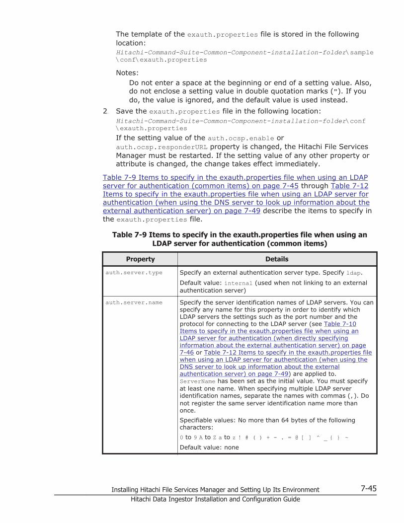
The template of the exauth.properties file is stored in the followinglocation:Hitachi-Command-Suite-Common-Component-installation-folder\sample\conf\exauth.propertiesNotes:
Do not enter a space at the beginning or end of a setting value. Also,do not enclose a setting value in double quotation marks ("). If youdo, the value is ignored, and the default value is used instead.
2. Save the exauth.properties file in the following location:Hitachi-Command-Suite-Common-Component-installation-folder\conf\exauth.propertiesIf the setting value of the auth.ocsp.enable orauth.ocsp.responderURL property is changed, the Hitachi File ServicesManager must be restarted. If the setting value of any other property orattribute is changed, the change takes effect immediately.
Table 7-9 Items to specify in the exauth.properties file when using an LDAPserver for authentication (common items) on page 7-45 through Table 7-12Items to specify in the exauth.properties file when using an LDAP server forauthentication (when using the DNS server to look up information about theexternal authentication server) on page 7-49 describe the items to specify inthe exauth.properties file.
Table 7-9 Items to specify in the exauth.properties file when using anLDAP server for authentication (common items)
Property Details
auth.server.type Specify an external authentication server type. Specify ldap.
Default value: internal (used when not linking to an externalauthentication server)
auth.server.name Specify the server identification names of LDAP servers. You canspecify any name for this property in order to identify whichLDAP servers the settings such as the port number and theprotocol for connecting to the LDAP server (see Table 7-10Items to specify in the exauth.properties file when using anLDAP server for authentication (when directly specifyinginformation about the external authentication server) on page7-46 or Table 7-12 Items to specify in the exauth.properties filewhen using an LDAP server for authentication (when using theDNS server to look up information about the externalauthentication server) on page 7-49) are applied to.ServerName has been set as the initial value. You must specifyat least one name. When specifying multiple LDAP serveridentification names, separate the names with commas (,). Donot register the same server identification name more thanonce.
Specifiable values: No more than 64 bytes of the followingcharacters:
0 to 9 A to Z a to z ! # ( ) + - . = @ [ ] ^ _ { } ~Default value: none
Installing Hitachi File Services Manager and Setting Up Its Environment 7-45Hitachi Data Ingestor Installation and Configuration Guide

Property Details
auth.group.mapping Specify whether to also link to an external authorization server.
Specify true to link to an external authorization server.
Specify false to not to link to an external authorization server.
Default value: false
Table 7-10 Items to specify in the exauth.properties file when using anLDAP server for authentication (when directly specifying information
about the external authentication server)
Attributes Details
protocol#1 Specify the protocol for connecting to the LDAP server. Thisattribute is required.
When communicating in plain text format, specify ldap. Whenusing StartTLS communication, specify tls.
Before specifying tls, make sure that one of the followingencryption methods can be used on the LDAP server.
• TLS_RSA_WITH_AES_256_CBC_SHA
• TLS_RSA_WITH_AES_128_CBC_SHA
• SSL_RSA_WITH_3DES_EDE_CBC_SHA
Specifiable values: ldap or tlsDefault value: none
host#2 Specify the host name or IP address of the LDAP server. If youspecify the host name, make sure beforehand that the host namecan be resolved to an IP address. If you specify the IP address,you can use either an IPv4 or IPv6 address. When specifying anIPv6 address, enclose it in square brackets ([]). This attribute isrequired.
Default value: none
port Specify the port number of the LDAP server. Make sure beforehandthat the port you specify is set as the listen port number on theLDAP server.
Specifiable values: 1 to 65535
Default value: 389
timeout Specify the amount of time to wait before timing out whenconnecting to the LDAP server. If you specify 0, the system waitsuntil a communication error occurs without timing out.
Specifiable values: 0 to 120 (seconds)
Default value: 15
attr Specify the attribute (Attribute Type) to use as the user ID duringauthentication.
• For the hierarchical structure model
Specify the name of the attribute containing the unique valueto be used for identifying the user. The value stored in thisattribute will be used as the user ID for Hitachi File ServicesManager.#3
7-46 Installing Hitachi File Services Manager and Setting Up Its EnvironmentHitachi Data Ingestor Installation and Configuration Guide

Attributes Details
For example, if you are using Active Directory and you want touse the Windows logon ID for the user ID of Hitachi FileServices Manager, specify the attribute name sAMAccountNamein which the Windows logon ID has been defined.
• For the flat model
Specify the RDN attribute name of the user entry.
For example, if the user's DN isuid=John,ou=People,dc=example,dc=com, specify the uidthat is the attribute name of the RDN uid=John.
sAMAccountName has been set as the initial value. This attribute isrequired.
Default value: none
basedn Specify the BaseDN, which is the DN of the entry that will be usedas the start point when searching for LDAP user information on theLDAP server. The user entries that are located in the hierarchybelow this DN will be checked during authentication. If charactersthat need to be escaped are included in the specified BaseDN,escape all of those characters correctly because the specified valuewill be passed to the LDAP server without change.
• For the hierarchical structure model
Specify the DN of the hierarchy that includes all of the userentries to be searched.
For example, for Figure 7-7 Example of the hierarchicalstructure model on page 7-43, specifycn=group,dc=example,dc=com.
• For the flat model
Specify the DN of the hierarchy just above the user entries tobe searched.
For example, for Figure 7-8 Example of the flat model on page7-43, specify ou=people,dc=example,dc=com.
This attribute is required. Specify the DN by following the rulesdefined in RFC4514. For example, if any of the following charactersare included in a DN, you need to use a backslash (\) to escapeeach character.
Spaces # + ; , < = > \Default value: none
retry.interval Specify the retry interval (in seconds) for when an attempt toconnect to the LDAP server fails.
Specifiable values: 1 to 60 (seconds)
Default value: 1
retry.times Specify the number of retries to attempt when an attempt toconnect to the LDAP server fails. If you specify 0, no retries areattempted.
Specifiable values: 0 to 50
Default value: 20
domain.name Specify the name of a domain managed by the LDAP server. Thisitem is required when an external authorization server is alsolinked to.
Installing Hitachi File Services Manager and Setting Up Its Environment 7-47Hitachi Data Ingestor Installation and Configuration Guide
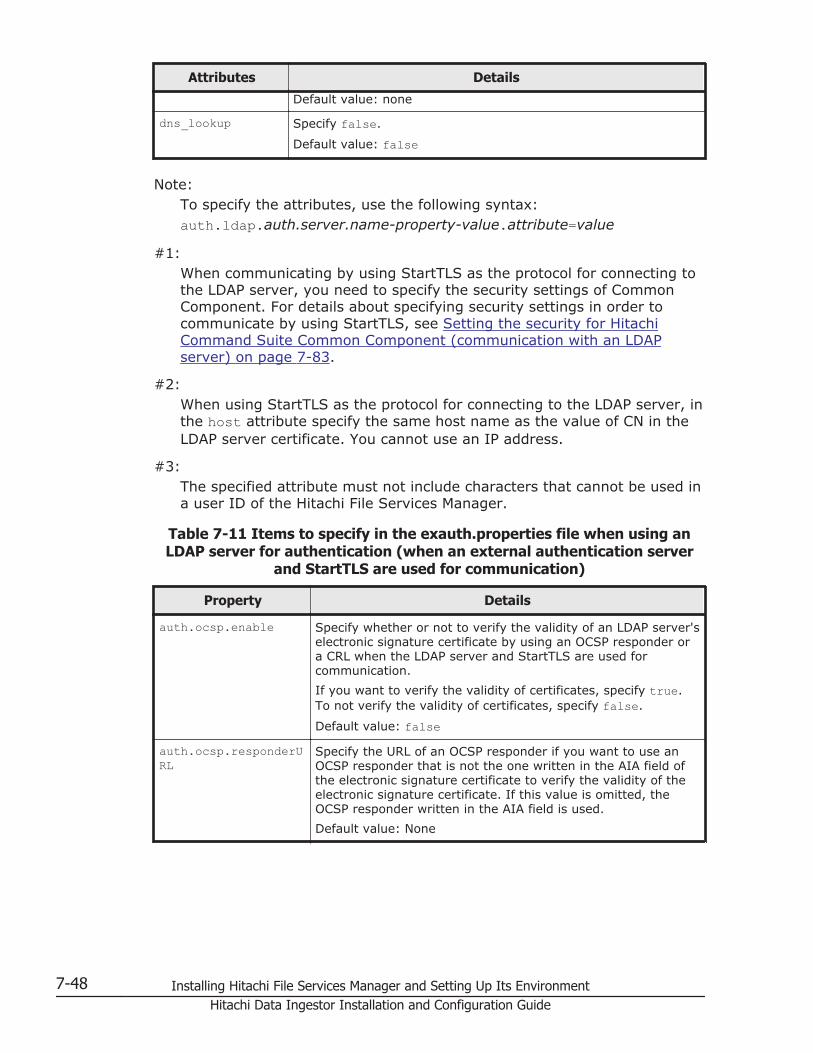
Attributes Details
Default value: none
dns_lookup Specify false.
Default value: false
Note:To specify the attributes, use the following syntax:auth.ldap.auth.server.name-property-value.attribute=value
#1:When communicating by using StartTLS as the protocol for connecting tothe LDAP server, you need to specify the security settings of CommonComponent. For details about specifying security settings in order tocommunicate by using StartTLS, see Setting the security for HitachiCommand Suite Common Component (communication with an LDAPserver) on page 7-83.
#2:When using StartTLS as the protocol for connecting to the LDAP server, inthe host attribute specify the same host name as the value of CN in theLDAP server certificate. You cannot use an IP address.
#3:The specified attribute must not include characters that cannot be used ina user ID of the Hitachi File Services Manager.
Table 7-11 Items to specify in the exauth.properties file when using anLDAP server for authentication (when an external authentication server
and StartTLS are used for communication)
Property Details
auth.ocsp.enable Specify whether or not to verify the validity of an LDAP server'selectronic signature certificate by using an OCSP responder ora CRL when the LDAP server and StartTLS are used forcommunication.
If you want to verify the validity of certificates, specify true.To not verify the validity of certificates, specify false.
Default value: falseauth.ocsp.responderURL
Specify the URL of an OCSP responder if you want to use anOCSP responder that is not the one written in the AIA field ofthe electronic signature certificate to verify the validity of theelectronic signature certificate. If this value is omitted, theOCSP responder written in the AIA field is used.
Default value: None
7-48 Installing Hitachi File Services Manager and Setting Up Its EnvironmentHitachi Data Ingestor Installation and Configuration Guide

Table 7-12 Items to specify in the exauth.properties file when using anLDAP server for authentication (when using the DNS server to look up
information about the external authentication server)
Attributes Details
protocol Specify the protocol for connecting to the LDAP server. Thisattribute is required.
Specifiable values: ldapDefault value: none
port Specify the port number of the LDAP server. Make sure beforehandthat the port you specify is set as the listen port number on theLDAP server.
Specifiable values: 1 to 65535
Default value: 389
timeout Specify the amount of time to wait before timing out whenconnecting to the LDAP server. If you specify 0, the system waitsuntil a communication error occurs without timing out.
Specifiable values: 0 to 120 (seconds)
Default value: 15
attr Specify the attribute (Attribute Type) to use as the user ID duringauthentication.
• For the hierarchical structure model
Specify the name of the attribute containing the unique valueto be used for identifying the user. The value stored in thisattribute will be used as the user ID for Hitachi File ServicesManager.#
For example, if you are using Active Directory and you want touse the Windows logon ID for the user ID of a Hitachi FileServices Manager, specify the attribute name sAMAccountNamein which the Windows logon ID has been defined.
• For the flat model
Specify the RDN attribute name of the user entry.
For example, if the user's DN isuid=John,ou=People,dc=example,dc=com, specify the uidthat is the attribute name of the RDN uid=John.
sAMAccountName has been set as the initial value. This attribute isrequired.
Default value: none
basedn Specify the BaseDN, which is the DN of the entry that will be usedas the start point when searching for LDAP user information on theLDAP server. The user entries that are located in the hierarchybelow this DN will be checked during authentication. If charactersthat need to be escaped are included in the specified BaseDN,escape all of those characters correctly because the specified valuewill be passed to the LDAP server without change.
• For the hierarchical structure model
Specify the DN of the hierarchy that includes all of the userentries to be searched.
Installing Hitachi File Services Manager and Setting Up Its Environment 7-49Hitachi Data Ingestor Installation and Configuration Guide
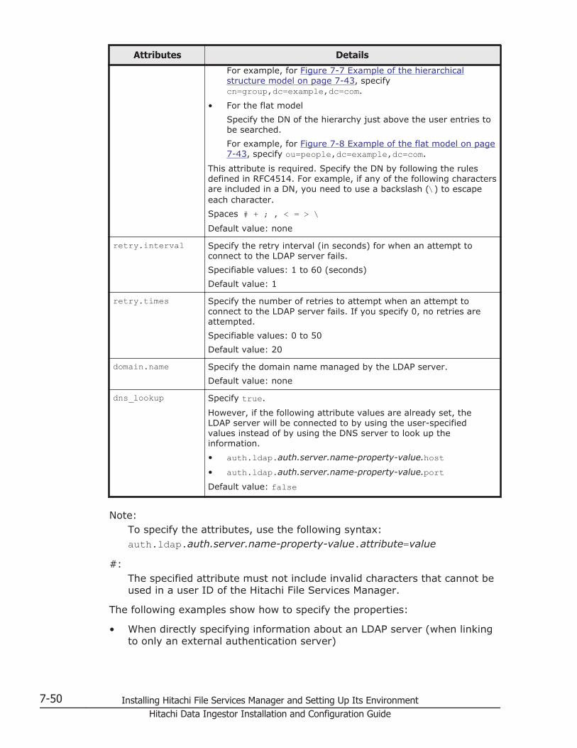
Attributes Details
For example, for Figure 7-7 Example of the hierarchicalstructure model on page 7-43, specifycn=group,dc=example,dc=com.
• For the flat model
Specify the DN of the hierarchy just above the user entries tobe searched.
For example, for Figure 7-8 Example of the flat model on page7-43, specify ou=people,dc=example,dc=com.
This attribute is required. Specify the DN by following the rulesdefined in RFC4514. For example, if any of the following charactersare included in a DN, you need to use a backslash (\) to escapeeach character.
Spaces # + ; , < = > \Default value: none
retry.interval Specify the retry interval (in seconds) for when an attempt toconnect to the LDAP server fails.
Specifiable values: 1 to 60 (seconds)
Default value: 1
retry.times Specify the number of retries to attempt when an attempt toconnect to the LDAP server fails. If you specify 0, no retries areattempted.
Specifiable values: 0 to 50
Default value: 20
domain.name Specify the domain name managed by the LDAP server.
Default value: none
dns_lookup Specify true.
However, if the following attribute values are already set, theLDAP server will be connected to by using the user-specifiedvalues instead of by using the DNS server to look up theinformation.
• auth.ldap.auth.server.name-property-value.host• auth.ldap.auth.server.name-property-value.portDefault value: false
Note:To specify the attributes, use the following syntax:auth.ldap.auth.server.name-property-value.attribute=value
#:The specified attribute must not include invalid characters that cannot beused in a user ID of the Hitachi File Services Manager.
The following examples show how to specify the properties:
• When directly specifying information about an LDAP server (when linkingto only an external authentication server)
7-50 Installing Hitachi File Services Manager and Setting Up Its EnvironmentHitachi Data Ingestor Installation and Configuration Guide
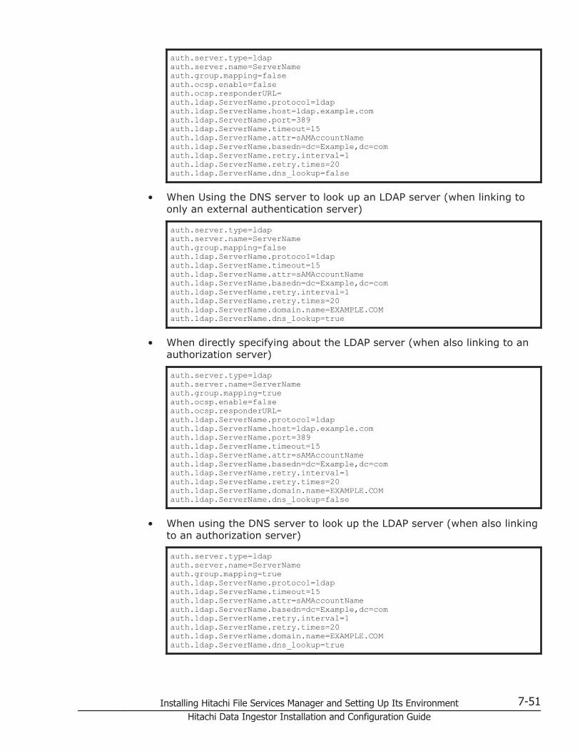
auth.server.type=ldapauth.server.name=ServerNameauth.group.mapping=falseauth.ocsp.enable=falseauth.ocsp.responderURL=auth.ldap.ServerName.protocol=ldapauth.ldap.ServerName.host=ldap.example.comauth.ldap.ServerName.port=389auth.ldap.ServerName.timeout=15auth.ldap.ServerName.attr=sAMAccountNameauth.ldap.ServerName.basedn=dc=Example,dc=comauth.ldap.ServerName.retry.interval=1auth.ldap.ServerName.retry.times=20auth.ldap.ServerName.dns_lookup=false
• When Using the DNS server to look up an LDAP server (when linking toonly an external authentication server)
auth.server.type=ldapauth.server.name=ServerNameauth.group.mapping=falseauth.ldap.ServerName.protocol=ldapauth.ldap.ServerName.timeout=15auth.ldap.ServerName.attr=sAMAccountNameauth.ldap.ServerName.basedn=dc=Example,dc=comauth.ldap.ServerName.retry.interval=1auth.ldap.ServerName.retry.times=20auth.ldap.ServerName.domain.name=EXAMPLE.COMauth.ldap.ServerName.dns_lookup=true
• When directly specifying about the LDAP server (when also linking to anauthorization server)
auth.server.type=ldapauth.server.name=ServerNameauth.group.mapping=trueauth.ocsp.enable=falseauth.ocsp.responderURL=auth.ldap.ServerName.protocol=ldapauth.ldap.ServerName.host=ldap.example.comauth.ldap.ServerName.port=389auth.ldap.ServerName.timeout=15auth.ldap.ServerName.attr=sAMAccountNameauth.ldap.ServerName.basedn=dc=Example,dc=comauth.ldap.ServerName.retry.interval=1auth.ldap.ServerName.retry.times=20auth.ldap.ServerName.domain.name=EXAMPLE.COMauth.ldap.ServerName.dns_lookup=false
• When using the DNS server to look up the LDAP server (when also linkingto an authorization server)
auth.server.type=ldapauth.server.name=ServerNameauth.group.mapping=trueauth.ldap.ServerName.protocol=ldapauth.ldap.ServerName.timeout=15auth.ldap.ServerName.attr=sAMAccountNameauth.ldap.ServerName.basedn=dc=Example,dc=comauth.ldap.ServerName.retry.interval=1auth.ldap.ServerName.retry.times=20auth.ldap.ServerName.domain.name=EXAMPLE.COMauth.ldap.ServerName.dns_lookup=true
Installing Hitachi File Services Manager and Setting Up Its Environment 7-51Hitachi Data Ingestor Installation and Configuration Guide

Setting LDAP user information (LDAP authentication)
By using the hcmdsldapuser command, you can register, on themanagement server, a user account used to search for LDAP userinformation. After registering a user account, you can use this command todelete such an account or check LDAP servers for which user accounts usedto search for LDAP user information have been registered on themanagement server.
This step is necessary in the following cases:
• When the data structure is the hierarchical model
• When the data structure is the flat model and an external authorizationserver is also linked to#
#:When registering an authorization group in Hitachi File ServicesManager by using the GUI, if you want to check whether thedistinguished name of the authorization group is registered on theexternal authorization server by using a user ID such as the Systemaccount registered in Hitachi File Services Manager, you need toregister a user account used to search for LDAP user information onthe management server.
In cases other than above, this step is not necessary, because LDAP userinformation is not searched during authentication and authorization. If a useraccount used to search for LDAP user information has been alreadyregistered, delete it.
Registering an account to search for LDAP user information (LDAPauthentication)
Use the hcmdsldapuser command to register a user account used to searchfor LDAP user information.
For a user account used to search for LDAP user information, register a useraccount that satisfies the following conditions:
• The user account is already registered in the LDAP server.
• The user account can bind to the DN specified forauth.ldap.auth.server.name-property-value.basedn in theexauth.properties file
• The user account can search the attributes for all entries below the DNspecified for auth.ldap.auth.server.name-property-value.basedn in theexauth.properties file
• The user account can reference the DN specified forauth.ldap.auth.server.name-property-value.basedn in theexauth.properties file
• The user account can reference the authorization groups that are underthe DN specified for auth.ldap.auth.server.name-property-value.basednin the exauth.properties file (when an external authorization server isalso linked to)
7-52 Installing Hitachi File Services Manager and Setting Up Its EnvironmentHitachi Data Ingestor Installation and Configuration Guide
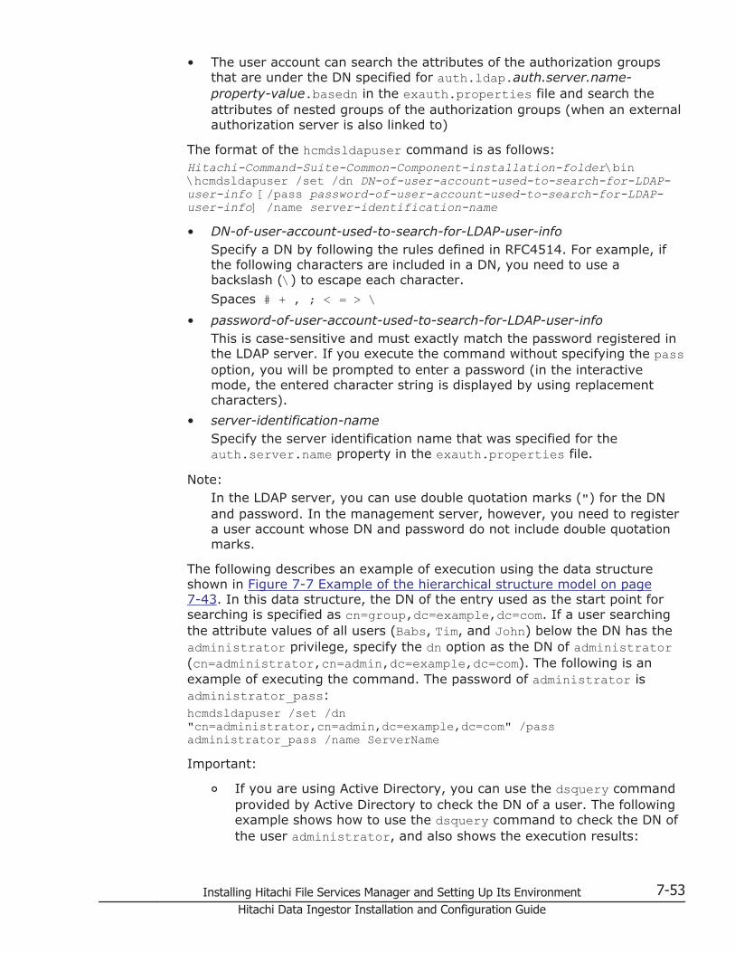
• The user account can search the attributes of the authorization groupsthat are under the DN specified for auth.ldap.auth.server.name-property-value.basedn in the exauth.properties file and search theattributes of nested groups of the authorization groups (when an externalauthorization server is also linked to)
The format of the hcmdsldapuser command is as follows:Hitachi-Command-Suite-Common-Component-installation-folder\bin\hcmdsldapuser /set /dn DN-of-user-account-used-to-search-for-LDAP-user-info [/pass password-of-user-account-used-to-search-for-LDAP-user-info] /name server-identification-name• DN-of-user-account-used-to-search-for-LDAP-user-info
Specify a DN by following the rules defined in RFC4514. For example, ifthe following characters are included in a DN, you need to use abackslash (\) to escape each character.
Spaces # + , ; < = > \• password-of-user-account-used-to-search-for-LDAP-user-info
This is case-sensitive and must exactly match the password registered inthe LDAP server. If you execute the command without specifying the passoption, you will be prompted to enter a password (in the interactivemode, the entered character string is displayed by using replacementcharacters).
• server-identification-nameSpecify the server identification name that was specified for theauth.server.name property in the exauth.properties file.
Note:In the LDAP server, you can use double quotation marks (") for the DNand password. In the management server, however, you need to registera user account whose DN and password do not include double quotationmarks.
The following describes an example of execution using the data structureshown in Figure 7-7 Example of the hierarchical structure model on page7-43. In this data structure, the DN of the entry used as the start point forsearching is specified as cn=group,dc=example,dc=com. If a user searchingthe attribute values of all users (Babs, Tim, and John) below the DN has theadministrator privilege, specify the dn option as the DN of administrator(cn=administrator,cn=admin,dc=example,dc=com). The following is anexample of executing the command. The password of administrator isadministrator_pass:hcmdsldapuser /set /dn "cn=administrator,cn=admin,dc=example,dc=com" /pass administrator_pass /name ServerNameImportant:
¢ If you are using Active Directory, you can use the dsquery commandprovided by Active Directory to check the DN of a user. The followingexample shows how to use the dsquery command to check the DN ofthe user administrator, and also shows the execution results:
Installing Hitachi File Services Manager and Setting Up Its Environment 7-53Hitachi Data Ingestor Installation and Configuration Guide

dsquery user -name administrator"CN=administrator,CN=admin,DC=example,DC=com"
¢ If the DN includes commas such ascn=administrator,cn=admin,dc=example,com, specify as follows:hcmdsldapuser /set /dn "cn=administrator,cn=admin,dc=example\,com" /pass administrator_pass /name ServerName
Deleting the account that searches for LDAP user information (LDAPauthentication)
To delete a user account used to search for LDAP user information, executethe following command.Hitachi-Command-Suite-Common-Component-installation-folder\bin\hcmdsldapuser /delete /name server-identification-name
Checking which LDAP servers have accounts that search for LDAPuser information (LDAP authentication)
To check the names of LDAP servers for which a user account used to searchfor LDAP user information has been registered on the management server,execute the following command.Hitachi-Command-Suite-Common-Component-installation-folder\bin\hcmdsldapuser /list
Checking the connection status of external authentication and authorizationservers (LDAP authentication)
By using the hcmdscheckauth command, you can make sure that the externalauthentication server and the external authorization server can properly beconnected to.Hitachi-Command-Suite-Common-Component-installation-folder\bin\hcmdscheckauth [/user user-ID /pass password] [/summary]• user-ID and password must match those of the user account that has
been registered in the LDAP server. user-ID must be the same value asthe one specified for the attribute auth.ldap.auth.server.name-property-value.attr in the exauth.properties file. However, you cannot specify auser account whose user-ID or password begins with a forward slash (/).
If you execute the command without specifying the user option or thepass option, you will be prompted to enter a user ID and password (inthe interactive mode, the entered character string is displayed by usingreplacement characters).
• If you execute the command with the summary option specified, theconfirmation message is displayed in summary format.
If you execute the hcmdscheckauth command, the settings in theexauth.properties file, and the connection status of the externalauthentication server and the external authorization server are checked in thefour phases described below. Check results are displayed for each phase.
Phase 1
7-54 Installing Hitachi File Services Manager and Setting Up Its EnvironmentHitachi Data Ingestor Installation and Configuration Guide

The command verifies that common properties (Table 7-9 Items tospecify in the exauth.properties file when using an LDAP server forauthentication (common items) on page 7-45) have been correctlyspecified in the exauth.properties file.
Phase 2The command verifies that the properties for the external authenticationserver and the external authorization server (Table 7-10 Items to specifyin the exauth.properties file when using an LDAP server for authentication(when directly specifying information about the external authenticationserver) on page 7-46 to Table 7-12 Items to specify in theexauth.properties file when using an LDAP server for authentication(when using the DNS server to look up information about the externalauthentication server) on page 7-49) have been correctly specified in theexauth.properties file.
Phase 3The command verifies that the external authentication server can beconnected to.
Phase 4If an external authorization server is also linked to, the command verifiesthat the external authorization server can be connected to andauthorization groups can be searched.
When a phase finishes normally, the following message is displayed:
KAPM15004-I The result of the configuration check of Phase X was normal.
Note: X is the phase number.
• Example of executing the hcmdscheckauth command when thehierarchical structure model is used:The following example shows how to execute the hcmdscheckauthcommand, using the user account John shown in Figure 7-7 Example ofthe hierarchical structure model on page 7-43.This example assumes that sAMAccountName has been specified inauth.ldap.auth.server.name-property-value.attr in theexauth.properties file. If the sAMAccountName attribute value of John isJohn_Smith, specify John_Smith in user-ID. If the password of John to beused on the LDAP server is John_pass, specify John_pass in password.hcmdscheckauth /user John_Smith /pass John_pass
• Example of executing the hcmdscheckauth command when the flat modelis used:The following example shows how to execute the hcmdscheckauthcommand, using the user account John shown in Figure 7-8 Example ofthe flat model on page 7-43.This example assumes that uid has been specified inauth.ldap.auth.server.name-property-value.attr in theexauth.properties file. As the RDN of John is given by uid=John,
Installing Hitachi File Services Manager and Setting Up Its Environment 7-55Hitachi Data Ingestor Installation and Configuration Guide

specify the RDN attribute value John in user-ID. If the password of Johnto be used on the LDAP server is John_pass, specify John_pass inpassword.hcmdscheckauth /user John /pass John_pass
Performing an external authentication by using a RADIUS serverTo authenticate the system administrator account by using a RADIUSserver, specify the following settings in Hitachi File Services Manager.
1. In the exauth.properties file on the management server, specifynecessary information.Necessary settings depend on whether only an external authenticationserver is linked to or an external authorization server is also linked to.You can use either of the following methods to define the LDAP server tobe used as an external authorization server:
¢ In the exauth.properties file, directly specify information about theLDAP server to connect to.Specify information such as IP address and port number in theexauth.properties file for each LDAP server.
¢ Use the DNS server to look up the LDAP server to connect to.Before using this method, you need to set up the DNS serverenvironment on the OS of the LDAP server. In addition, you need toregister the host name, port number, and domain name of the LDAPserver in the SRV records of the DNS server.
Important:- To use StartTLS for communication between the managementserver and the LDAP server, you need to directly specify informationabout the LDAP server to connect to in the exauth.properties file.
- When using the DNS server to look up the LDAP server to connectto, it might take longer for users to log in.
2. When also linking to an external authorization server, on themanagement server, register a user account used to search for userinformation on the LDAP server.
3. On the RADIUS server, register the accounts of users who will use HitachiFile Services Manager.User IDs and passwords must consist of characters that can be used inHitachi File Services Manager. Specify 1 to 256 bytes of the followingcharacters:0 to 9 A to Z a to z ! # $ % & ' ( ) * + - . = @ \ ^ _ |In Hitachi File Services Manager, user IDs are not case-sensitive. Thecombination of character types for passwords must follow the settings inthe external authentication server.
4. Specify a shared secret on the management server for communicatingwith the RADIUS server.
5. Register accounts and set permissions by using the GUI.
7-56 Installing Hitachi File Services Manager and Setting Up Its EnvironmentHitachi Data Ingestor Installation and Configuration Guide

When linking with only an external authentication server:
¢ Register users.
¢ Change the user authentication method.This operation is required if you want to change the authenticationmethod for existing users.
¢ Register users into user groups.
¢ Configure both user management and the operation permissions forHitachi File Services Manager.
When also linking with an external authorization server:
¢ Register authorization groups.
¢ Configure both user management and the operation permissions forHitachi File Services Manager.
Reference note:Users who belong to nested groups of a registered authorization groupcan now also use Hitachi File Services Manager via the roles(permissions) set for the authorization group.
6. Use the hcmdscheckauth command to make sure that the externalauthentication server and the external authorization server can beproperly connected to.
The following sections describe operations you need to perform on themanagement server.
Modifying exauth.properties for RADIUS authentication
This section describes the settings required for the exauth.properties file inorder to use a RADIUS server to authenticate users.
1. Specify values for the following properties in the exauth.properties file:
¢ Common properties (Table 7-13 Items to specify in theexauth.properties file when using a RADIUS server for authentication(common items) on page 7-58)
¢ Properties for an external authentication server (Table 7-14 Items tospecify in the exauth.properties file when using a RADIUS server forauthentication (settings for the external authentication server) onpage 7-59)Specify these property values for each RADIUS server.
¢ Properties for an external authorization serverThese properties need to be set when an external authorization serveris also linked to. Specify information about the LDAP server for eachdomain.The items you need to specify differ depending on whether youdirectly specify information about the LDAP server (Table 7-15 Itemsto specify in the exauth.properties file when using a RADIUS serverfor authentication (common settings for the external authorizationserver) on page 7-60 to Table 7-17 Items to specify in the
Installing Hitachi File Services Manager and Setting Up Its Environment 7-57Hitachi Data Ingestor Installation and Configuration Guide
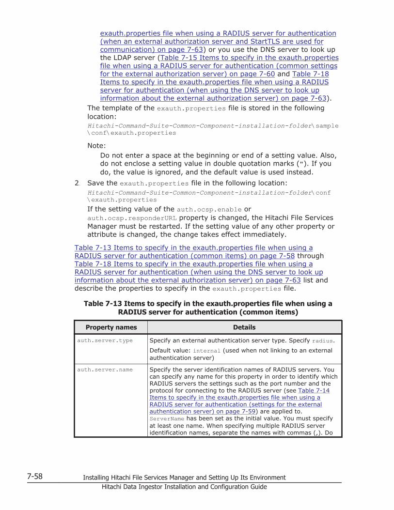
exauth.properties file when using a RADIUS server for authentication(when an external authorization server and StartTLS are used forcommunication) on page 7-63) or you use the DNS server to look upthe LDAP server (Table 7-15 Items to specify in the exauth.propertiesfile when using a RADIUS server for authentication (common settingsfor the external authorization server) on page 7-60 and Table 7-18Items to specify in the exauth.properties file when using a RADIUSserver for authentication (when using the DNS server to look upinformation about the external authorization server) on page 7-63).
The template of the exauth.properties file is stored in the followinglocation:Hitachi-Command-Suite-Common-Component-installation-folder\sample\conf\exauth.propertiesNote:
Do not enter a space at the beginning or end of a setting value. Also,do not enclose a setting value in double quotation marks ("). If youdo, the value is ignored, and the default value is used instead.
2. Save the exauth.properties file in the following location:Hitachi-Command-Suite-Common-Component-installation-folder\conf\exauth.propertiesIf the setting value of the auth.ocsp.enable orauth.ocsp.responderURL property is changed, the Hitachi File ServicesManager must be restarted. If the setting value of any other property orattribute is changed, the change takes effect immediately.
Table 7-13 Items to specify in the exauth.properties file when using aRADIUS server for authentication (common items) on page 7-58 throughTable 7-18 Items to specify in the exauth.properties file when using aRADIUS server for authentication (when using the DNS server to look upinformation about the external authorization server) on page 7-63 list anddescribe the properties to specify in the exauth.properties file.
Table 7-13 Items to specify in the exauth.properties file when using aRADIUS server for authentication (common items)
Property names Details
auth.server.type Specify an external authentication server type. Specify radius.
Default value: internal (used when not linking to an externalauthentication server)
auth.server.name Specify the server identification names of RADIUS servers. Youcan specify any name for this property in order to identify whichRADIUS servers the settings such as the port number and theprotocol for connecting to the RADIUS server (see Table 7-14Items to specify in the exauth.properties file when using aRADIUS server for authentication (settings for the externalauthentication server) on page 7-59) are applied to.ServerName has been set as the initial value. You must specifyat least one name. When specifying multiple RADIUS serveridentification names, separate the names with commas (,). Do
7-58 Installing Hitachi File Services Manager and Setting Up Its EnvironmentHitachi Data Ingestor Installation and Configuration Guide

Property names Details
not register the same server identification name more thanonce.
Specifiable values: No more than 64 bytes of the followingcharacters:
0 to 9 A to Z a to z ! # ( ) + - . = @ [ ] ^ _ { } ~Default value: none
auth.group.mapping Specify whether to also link to an external authorization server.
Specify true to link to an external authorization server.
Specify false to not to link to an external authorization server.
Default value: false
Table 7-14 Items to specify in the exauth.properties file when using aRADIUS server for authentication (settings for the external authentication
server)
Attributes Details
protocol Specify the protocol for RADIUS server authentication.This attribute is required.
Specifiable values: PAP or CHAPDefault value: none
host#1 Specify the host name or IP address of the RADIUSserver. If you specify the host name, make surebeforehand that the host name can be resolved to anIP address. If you specify the IP address, you can useeither an IPv4 or IPv6 address. When specifying anIPv6 address, enclose it in square brackets ([]). Thisattribute is required.
Default value: none
port Specify the port number for RADIUS serverauthentication. Make sure beforehand that the port youspecify is set as the listen port number on the RADIUSserver.
Specifiable values: 1 to 65535
Default value: 1812
timeout Specify the amount of time to wait before timing outwhen connecting to the RADIUS server.
Specifiable values: 1 to 65535 (seconds)
Default value: 1
retry.times Specify the number of retries to attempt when anattempt to connect to the RADIUS server fails. If youspecify 0, no retries are attempted.
Specifiable values: 0 to 50
Default value: 3
attr.NAS-Identifier#2 Specify the host name of the HDI management server.The RADIUS server uses this attribute value to identify
Installing Hitachi File Services Manager and Setting Up Its Environment 7-59Hitachi Data Ingestor Installation and Configuration Guide

Attributes Details
the management server. The host name of themanagement server has been set as the initial value.
Specifiable values: Specify no more than 253 bytes ofthe following characters:
0 to 9 A to Z a to z ! " # $ % & ' ( ) * + ,- . / : ; < = > ? @ [ \ ] ^ _ ` { | } ~Default value: none
attr.NAS-IP-Address#2 Specify the IPv4 address of the HDI managementserver. The RADIUS server uses this attribute value toidentify the management server.
If the format of the address is invalid, this property isdisabled.
Default value: none
attr.NAS-IPv6-Address#2 Specify the IPv6 address of the HDI managementserver. The RADIUS server uses this attribute value toidentify the management server. Enclose the IPv6address in square brackets ([]).
If the format of the address is invalid, this property isdisabled.
Default value: none
Note:To specify the attributes, use the following syntax:auth.radius.auth.server.name-property-value.attribute=value
#1:When linking to an external authorization server that is running on thesame computer and using StartTLS as the protocol for connecting to theLDAP server, in the host attribute specify the same host name as thevalue of CN in the LDAP server certificate. You cannot use an IP address.
#2:You must specify exactly one of the following: attr.NAS-Identifier,attr.NAS-IP-Address, or attr.NAS-IPv6-Address.
Table 7-15 Items to specify in the exauth.properties file when using aRADIUS server for authentication (common settings for the external
authorization server)
Attributes Details
domain.name Specify the name of a domain managed by the LDAP server.This item is required when an external authorization server isalso linked to.
Default value: none
dns_lookup Specify whether to use the DNS server to look up theinformation about the LDAP server.
7-60 Installing Hitachi File Services Manager and Setting Up Its EnvironmentHitachi Data Ingestor Installation and Configuration Guide

Attributes Details
If you want to directly specify information about the LDAPserver in the exauth.properties file, specify false.
If you want to use the DNS server to look up the information,specify true.
However, if the following attribute values are already set, theLDAP server will be connected to by using the user-specifiedvalues instead of by using the DNS server to look up theinformation.
• auth.group.domain-name.host• auth.group.domain-name.portDefault value: false
Note:To specify the attributes, use the following syntax:auth.radius.auth.server.name-property-value.attribute=value
Table 7-16 Items to specify in the exauth.properties file when using aRADIUS server for authentication (when directly specifying information
about the external authorization server)
Attributes Details
protocol#1 Specify the protocol for connecting to the LDAP server.
When communicating in plain text format, specify ldap. Whenusing StartTLS communication, specify tls.
Before specifying tls, make sure that one of the followingencryption methods can be used on the LDAP server.
• TLS_RSA_WITH_AES_256_CBC_SHA
• TLS_RSA_WITH_AES_128_CBC_SHA
• SSL_RSA_WITH_3DES_EDE_CBC_SHA
Specifiable values: ldap or tlsDefault value: ldap
host#2 If the external authentication server and the external authorizationserver are running on different computers, specify the host nameor IP address of the LDAP server. If you specify the host name,make sure beforehand that the host name can be resolved to an IPaddress. If you specify the IP address, you can use either an IPv4or IPv6 address. When specifying an IPv6 address, enclose it insquare brackets ([]).
If you omit this attribute, the external authentication server andthe external authorization server are assumed to be running onthe same computer.
Default value: none
port Specify the port number of the LDAP server. Make sure beforehandthat the port you specify is set as the listen port number on theLDAP server.
Specifiable values: 1 to 65535
Installing Hitachi File Services Manager and Setting Up Its Environment 7-61Hitachi Data Ingestor Installation and Configuration Guide

Attributes Details
Default value: 389
basedn Specify the BaseDN, which is the DN of the entry that will be usedas the start point when searching for LDAP user information on theLDAP server. The user entries that are located in the hierarchybelow this DN will be checked during authorization.
Specify the DN of the hierarchy that includes all of the user entriesto be searched.
Specify the DN by following the rules defined in RFC4514. Forexample, if any of the following characters are included in a DN,you need to use a backslash (\) to escape each character.
Spaces # + ; , < = > \If characters that need to be escaped are included in the specifiedBaseDN, escape all of those characters correctly because thespecified value will be passed to the LDAP server without change.
If you omit this attribute, the value specified in thedefaultNamingContext property of Active Directory is assumed asthe BaseDN.
Default value: none
timeout Specify the amount of time to wait before timing out whenconnecting to the LDAP server. If you specify 0, the system waitsuntil a communication error occurs without timing out.
Specifiable values: 0 to 120 (seconds)
Default value: 15
retry.interval Specify the retry interval (in seconds) for when an attempt toconnect to the LDAP server fails.
Specifiable values: 1 to 60 (seconds)
Default value: 1
retry.times Specify the number of retries to attempt when an attempt toconnect to the LDAP server fails. If you specify 0, no retries areattempted.
Specifiable values: 0 to 50
Default value: 20
Note:To specify the attributes, use the following syntax:auth.group.domain-name.attribute=value
For domain-name, specify the value specified forauth.radius.auth.server.name-property-value.domain.name.
#1:When communicating by using StartTLS as the protocol for connecting tothe LDAP server, you need to specify the security settings of CommonComponent. For details about specifying security settings in order tocommunicate by using StartTLS, see Setting the security for HitachiCommand Suite Common Component (communication with an LDAPserver) on page 7-83.
7-62 Installing Hitachi File Services Manager and Setting Up Its EnvironmentHitachi Data Ingestor Installation and Configuration Guide

#2:When the external authentication server and the external authorizationserver are running on different computers and when using StartTLS asthe protocol for connecting to the LDAP server, in the host attributespecify the same host name as the value of CN in the LDAP servercertificate. You cannot use an IP address.
Table 7-17 Items to specify in the exauth.properties file when using aRADIUS server for authentication (when an external authorization server
and StartTLS are used for communication)
Property Details
auth.ocsp.enable Specify whether or not to verify the validity of an LDAP server'selectronic signature certificate by using an OCSP responder ora CRL when the LDAP server and StartTLS are used forcommunication.
If you want to verify the validity of certificates, specify true.To not verify the validity of certificates, specify false.
Default value: falseauth.ocsp.responderURL
Specify the URL of an OCSP responder if you want to use anOCSP responder that is not the one written in the AIA field ofthe electronic signature certificate to verify the validity of theelectronic signature certificate. If this value is omitted, theOCSP responder written in the AIA field is used.
Default value: None
Table 7-18 Items to specify in the exauth.properties file when using aRADIUS server for authentication (when using the DNS server to look up
information about the external authorization server)
Attributes Details
protocol Specify the protocol for connecting to the LDAP server.
Specifiable values: ldapDefault value: ldap
port Specify the port number of the LDAP server. Make sure beforehandthat the port you specify is set as the listen port number on theLDAP server.
Specifiable values: 1 to 65535
Default value: 389
basedn Specify the BaseDN, which is the DN of the entry that will be usedas the start point when searching for LDAP user information on theLDAP server. The user entries that are located in the hierarchybelow this DN will be checked during authorization.
Specify the DN of the hierarchy that includes all of the user entriesto be searched.
Specify the DN by following the rules defined in RFC4514. Forexample, if any of the following characters are included in a DN,you need to use a backslash (\) to escape each character.
Installing Hitachi File Services Manager and Setting Up Its Environment 7-63Hitachi Data Ingestor Installation and Configuration Guide

Attributes Details
Spaces # + ; , < = > \If characters that need to be escaped are included in the specifiedBaseDN, escape all of those characters correctly because thespecified value will be passed to the LDAP server without change.
If you omit this attribute, the value specified in thedefaultNamingContext property of Active Directory is assumed asthe BaseDN.
Default value: none
timeout Specify the amount of time to wait before timing out whenconnecting to the LDAP server. If you specify 0, the system waitsuntil a communication error occurs without timing out.
Specifiable values: 0 to 120 (seconds)
Default value: 15
retry.interval Specify the retry interval (in seconds) for when an attempt toconnect to the LDAP server fails.
Specifiable values: 1 to 60 (seconds)
Default value: 1
retry.times Specify the number of retries to attempt when an attempt toconnect to the LDAP server fails. If you specify 0, no retries areattempted.
Specifiable values: 0 to 50
Default value: 20
Note:To specify the attributes, use the following syntax:auth.group.domain-name.attribute=value
For domain-name, specify the value specified forauth.radius.auth.server.name-property-value.domain.name.
The following examples show how to specify the properties:
• When linking to only an external authentication server
auth.server.type=radiusauth.server.name=ServerNameauth.group.mapping=falseauth.radius.ServerName.protocol=PAPauth.radius.ServerName.host=radius.example.comauth.radius.ServerName.port=1812auth.radius.ServerName.timeout=1auth.radius.ServerName.retry.times=3auth.radius.ServerName.attr.NAS-Identifier=host_A
• When directly specifying information about an external authorizationserver
auth.server.type=radiusauth.server.name=ServerNameauth.group.mapping=trueauth.ocsp.enable=falseauth.ocsp.responderURL=
7-64 Installing Hitachi File Services Manager and Setting Up Its EnvironmentHitachi Data Ingestor Installation and Configuration Guide

auth.radius.ServerName.protocol=PAPauth.radius.ServerName.host=radius.example.comauth.radius.ServerName.port=1812auth.radius.ServerName.timeout=1auth.radius.ServerName.retry.times=3auth.radius.ServerName.attr.NAS-Identifier=host_Aauth.radius.ServerName.domain.name=EXAMPLE.COMauth.radius.ServerName.dns_lookup=falseauth.group.EXAMPLE.COM.protocol=ldapauth.group.EXAMPLE.COM.host=ldap.example.comauth.group.EXAMPLE.COM.port=389auth.group.EXAMPLE.COM.basedn=dc=Example,dc=comauth.group.EXAMPLE.COM.timeout=15auth.group.EXAMPLE.COM.retry.interval=1auth.group.EXAMPLE.COM.retry.times=20
• When using the DNS server to look up an external authorization server
auth.server.type=radiusauth.server.name=ServerNameauth.group.mapping=trueauth.radius.ServerName.protocol=PAPauth.radius.ServerName.host=radius.example.comauth.radius.ServerName.port=1812auth.radius.ServerName.timeout=1auth.radius.ServerName.retry.times=3auth.radius.ServerName.attr.NAS-Identifier=host_Aauth.radius.ServerName.domain.name=EXAMPLE.COMauth.radius.ServerName.dns_lookup=trueauth.group.EXAMPLE.COM.protocol=ldapauth.group.EXAMPLE.COM.basedn=dc=Example,dc=comauth.group.EXAMPLE.COM.timeout=15auth.group.EXAMPLE.COM.retry.interval=1auth.group.EXAMPLE.COM.retry.times=20
Setting LDAP user information (RADIUS authentication)
When using an LDAP server as an external authorization server, by using thehcmdsldapuser command, you can register, on the management server, auser account used to search for LDAP user information. After registering auser account, you can use this command to delete such an account or checkLDAP servers for which user accounts used to search for LDAP userinformation have been registered on the management server.
Registering an account to search for LDAP user information(RADIUS authentication)
Use the hcmdsldapuser command to register a user account used to searchfor LDAP user information.
For a user account used to search for LDAP user information, register a useraccount that satisfies the following conditions:
• The user account is already registered in the LDAP server.
• The user account can bind to the DN specified for auth.group.domain-name.basedn in the exauth.properties file
Installing Hitachi File Services Manager and Setting Up Its Environment 7-65Hitachi Data Ingestor Installation and Configuration Guide

• The user account can search the attributes for all entries below the DNspecified for auth.group.domain-name.basedn in theexauth.properties file
• The user account can reference the DN specified for auth.group.domain-name.basedn in the exauth.properties file
• The user account can reference the authorization groups that are underthe DN specified for auth.group.domain-name.basedn in theexauth.properties file.
• The user account can search the attributes of the authorization groupsthat are under the DN specified for auth.group.domain-name.basedn inthe exauth.properties file and search the attributes of nested groups ofthe authorization groups
The format of the hcmdsldapuser command is as follows:Hitachi-Command-Suite-Common-Component-installation-folder\bin\hcmdsldapuser /set /dn DN-of-user-account-used-to-search-for-LDAP-user-info [/pass password-of-user-account-used-to-search-for-LDAP-user-info] /name domain-name• DN-of-user-account-used-to-search-for-LDAP-user-info
Specify a DN by following the rules defined in RFC4514. For example, ifthe following characters are included in a DN, you need to use abackslash (\) to escape each character.
Spaces # + , ; < = > \• password-of-user-account-used-to-search-for-LDAP-user-info
This is case-sensitive and must exactly match the password registered inthe LDAP server. If you execute the command without specifying the passoption, you will be prompted to enter a password (in the interactivemode, the entered character string is displayed by using replacementcharacters).
• domain-nameSpecify the domain name specified for auth.radius.auth.server.name-property-value.domain.name in the exauth.properties file.
Note:In the LDAP server, you can use double quotation marks (") for the DNand password. In the management server, however, you need to registera user account whose DN and password do not include double quotationmarks.
Important:
¢ You can use the dsquery command provided by Active Directory tocheck the DN of a user. The following example shows how to use thedsquery command to check the DN of the user administrator, andalso shows the execution results:dsquery user -name administrator"CN=administrator,CN=admin,DC=example,DC=com"
¢ If the DN includes commas such ascn=administrator,cn=admin,dc=example,com, specify as follows:
7-66 Installing Hitachi File Services Manager and Setting Up Its EnvironmentHitachi Data Ingestor Installation and Configuration Guide

hcmdsldapuser /set /dn "cn=administrator,cn=admin,dc=example\,com" /pass administrator_pass /name ServerName
Deleting the account that searches for LDAP user information(RADIUS authentication)
To delete a user account used to search for LDAP user information, executethe following command.Hitachi-Command-Suite-Common-Component-installation-folder\bin\hcmdsldapuser /delete /name domain-name
Checking which LDAP servers have accounts that search for LDAPuser information (RADIUS authentication)
To check the names of LDAP servers for which a user account used to searchfor LDAP user information has been registered on the management server,execute the following command:Hitachi-Command-Suite-Common-Component-installation-folder\bin\hcmdsldapuser /list
Setting a shared secret (RADIUS authentication)
By using the hcmdsradiussecret command, you can specify a shared secreton the management server to communicate with the RADIUS server. Afterspecifying a shared secret, you can use this command to delete a sharedsecret or to list the server identification names of external authenticationservers in which a shared secret has been registered.
Specifying a shared secret (RADIUS authentication)
To specify a shared secret by using the hcmdsradiussecret command,execute the following command.Hitachi-Command-Suite-Common-Component-installation-folder\bin\hcmdsradiussecret [/set shared-secret] /name RADIUS-server-indication-name
• If you execute the command without specifying the set option, you willbe prompted to enter a shared secret key (in the interactive mode, theentered character string is displayed by using replacement characters).
• RADIUS-server-indication-name must match a server indication namespecified for the auth.server.name property in the exauth.propertiesfile.
The following example shows how to execute the hcmdsradiussecretcommand when the shared secret is secret01 and the server identificationname of the RADIUS server is ServerName.hcmdsradiussecret /set secret01 /name ServerName
Deleting a shared secret (RADIUS authentication)
To delete a shared secret, execute the following command.
Installing Hitachi File Services Manager and Setting Up Its Environment 7-67Hitachi Data Ingestor Installation and Configuration Guide

Hitachi-Command-Suite-Common-Component-installation-folder\bin\hcmdsradiussecret /delete /name RADIUS-server-indication-name
Listing the IDs of RADIUS servers that have shared secrets (RADIUSauthentication)
To list the server identification names of RADIUS servers in which a sharedsecret has been registered, execute the following command:Hitachi-Command-Suite-Common-Component-installation-folder\bin\hcmdsradiussecret /list
Checking the connection status of external authentication and authorizationservers (RADIUS authentication)
By using the hcmdscheckauth command, you can make sure that the externalauthentication server and the external authorization server can be properlyconnected to.Hitachi-Command-Suite-Common-Component-installation-folder\bin\hcmdscheckauth [/user user-ID /pass password] [/summary]• user-ID and password must match those of the user account that has
been registered in the RADIUS server. However, you cannot specify auser account whose user-ID or password begins with a forward slash (/).
If you execute the command without specifying the user option or thepass option, you will be prompted to enter a user ID and password (inthe interactive mode, the entered character string is displayed by usingreplacement characters).
• If you execute the command with the summary option specified, theconfirmation message is displayed in summary format.
If you execute the hcmdscheckauth command, the settings in theexauth.properties file, and the connection status of the externalauthentication server and the external authorization server are checked in thefour phases described below. Check results are displayed for each phase.
Phase 1The command verifies that common properties (Table 7-13 Items tospecify in the exauth.properties file when using a RADIUS server forauthentication (common items) on page 7-58) have been correctlyspecified in the exauth.properties file.
Phase 2The command verifies that the properties for the external authenticationserver (Table 7-14 Items to specify in the exauth.properties file whenusing a RADIUS server for authentication (settings for the externalauthentication server) on page 7-59) and properties for the externalauthorization server (Table 7-15 Items to specify in the exauth.propertiesfile when using a RADIUS server for authentication (common settings forthe external authorization server) on page 7-60 through Table 7-18 Itemsto specify in the exauth.properties file when using a RADIUS server forauthentication (when using the DNS server to look up information about
7-68 Installing Hitachi File Services Manager and Setting Up Its EnvironmentHitachi Data Ingestor Installation and Configuration Guide

the external authorization server) on page 7-63) have been correctlyspecified in the exauth.properties file.
Phase 3The command verifies that the external authentication server can beconnected to.
Phase 4If an external authorization server is also linked to, the command verifiesthat the external authorization server can be connected to andauthorization groups can be searched.
When a phase finishes normally, the following message is displayed:
KAPM15004-I The result of the configuration check of Phase X was normal.
Note: X is the phase number.
Performing an external authentication by using a KDC serverTo authenticate the system administrator account by using a KDCserver, specify the following settings in Hitachi File Services Manager.
1. In the exauth.properties file on the management server, specifynecessary information.Necessary settings depend on whether only an external authenticationserver is linked to or an external authorization server is also linked to.You can use either of the following methods to define the KDC server tobe used as an external authorization server:
¢ In the exauth.properties file, directly specify information about theKDC server to connect to.Specify information about the KDC server, such as the IP address andport number, in the exauth.properties file for each realm.
¢ Use the DNS server to look up the KDC server to connect to.Specify information about the DNS server that manages KDC serversin the exauth.properties file.
In addition, before using this method, you need to register the hostname, port number, and realm name of the KDC server in the SRVrecords of the DNS server.
Important:- To use StartTLS for communication between the managementserver and the LDAP server, you need to directly specify informationabout the KDC server to connect to in the exauth.properties file.
- When using the DNS server to look up the KDC server to connectto, it might take longer for users to log in.
2. When also linking to an external authorization server, on themanagement server, register a user account used to search for userinformation on the LDAP server.
Installing Hitachi File Services Manager and Setting Up Its Environment 7-69Hitachi Data Ingestor Installation and Configuration Guide

3. On the KDC server, register the accounts of users who will use Hitachi FileServices Manager.User IDs and passwords must consist of characters that can be used inHitachi File Services Manager. Specify 1 to 256 bytes of the followingcharacters:0 to 9 A to Z a to z ! # $ % & ' ( ) * + - . = @ \ ^ _ |In Hitachi File Services Manager, user IDs are not case-sensitive. Thecombination of character types for passwords must follow the settings inthe external authentication server.
4. Register accounts and set permissions by using the GUI.When linking with only an external authentication server:
¢ Register users.
¢ Change the user authentication method.This operation is required if you want to change the authenticationmethod for existing users.
¢ Register users into user groups.
¢ Configure both user management and the operation permissions forHitachi File Services Manager.
When also linking with an external authorization server:
¢ Register authorization groups.
¢ Configure both user management and the operation permissions forHitachi File Services Manager.
Reference note:Users who belong to nested groups of a registered authorization groupcan now also use Hitachi File Services Manager via the roles(permissions) set for the authorization group.
5. Use the hcmdscheckauth command to make sure that the externalauthentication server and the external authorization server can beproperly connected to.
The following sections describe operations you need to perform on themanagement server.
Modifying exauth.properties for Kerberos authentication
This section describes the settings required for the exauth.properties file inorder to use a KDC server to authenticate users.
1. Specify values for the necessary properties in the exauth.propertiesfile:
¢ Common properties (Table 7-19 Items to specify in theexauth.properties file when using a KDC server for authentication(common items) on page 7-71)
¢ Properties for an external authentication serverSpecify these property values for each KDC server.
7-70 Installing Hitachi File Services Manager and Setting Up Its EnvironmentHitachi Data Ingestor Installation and Configuration Guide

The items you need to specify differ depending on whether youdirectly specify information about the KDC server (Table 7-20 Itemsto specify in the exauth.properties file when using a KDC server forauthentication (when directly specifying information about theexternal authentication server) on page 7-72) or you use the DNSserver to look up the KDC server (Table 7-21 Items to specify in theexauth.properties file when using a KDC server for authentication(when using the DNS server to look up information about the externalauthentication server) on page 7-74).
¢ Properties for an external authorization server (Table 7-22 Items tospecify in the exauth.properties file when using a KDC server forauthentication (settings for the external authorization server) on page7-75 and Table 7-23 Items to specify in the exauth.properties filewhen using a KDC server for authentication (when an externalauthorization server and StartTLS are used for communication) onpage 7-76)These properties need to be set if you directly specify informationabout the KDC server and an external authorization server is alsolinked. Specify the properties for each realm.
The template of the exauth.properties file is stored in the followinglocation:Hitachi-Command-Suite-Common-Component-installation-folder\sample\conf\exauth.propertiesNote:
Do not enter a space at the beginning or end of a setting value. Also,do not enclose a setting value in double quotation marks ("). If youdo, the value is ignored, and the default value is used instead.
2. Save the exauth.properties file in the following location:Hitachi-Command-Suite-Common-Component-installation-folder\conf\exauth.propertiesIf the setting value of the auth.ocsp.enable orauth.ocsp.responderURL property is changed, the Hitachi File ServicesManager must be restarted. If the setting value of any other property orattribute is changed, the change takes effect immediately.
Table 7-19 Items to specify in the exauth.properties file when using a KDCserver for authentication (common items) on page 7-71 through Table 7-23Items to specify in the exauth.properties file when using a KDC server forauthentication (when an external authorization server and StartTLS are usedfor communication) on page 7-76 list and describe the properties to specifyin the exauth.properties file.
Table 7-19 Items to specify in the exauth.properties file when using a KDCserver for authentication (common items)
Property names Details
auth.server.type Specify an external authentication server type. Specifykerberos.
Installing Hitachi File Services Manager and Setting Up Its Environment 7-71Hitachi Data Ingestor Installation and Configuration Guide

Property names Details
Default value: internal (used when not linking to anexternal authentication server)
auth.group.mapping Specify whether to also link to an external authorizationserver.
Specify true to link to an external authorization server.
Specify false to not to link to an external authorizationserver.
Default value: false
Table 7-20 Items to specify in the exauth.properties file when using a KDCserver for authentication (when directly specifying information about the
external authentication server)
Attributes Details
default_realm Specify the default realm name. If you specify auser ID but not a realm name in the loginwindow of the GUI, the user is authenticated asa user who belongs to the realm specified forthis attribute. This attribute is required.
Default value: none
dns_lookup_kdc Specify false.
Default value: falsedefault_tkt_enctypes Specify the encryption type used for Kerberos
authentication. This property is enabled only ifthe management server OS is Windows.
You can use the following encryption types:
• aes128-cts
• rc4-hmac
• des3-cbc-sha1
• des-cbc-md5
• des-cbc-crc
If you want to specify multiple encryption types,use a comma to separate the encryption types.
Among the specified encryption types, anencryption type that is supported by both themanagement server OS and a KDC server willbe used.
Default value: None (DES-CBC-MD5 is used forauthentication.)
clockskew Specify the acceptable range of differencebetween the management server time and KDCserver time. If the difference exceeds this value,an authentication error occurs.
Specifiable values: 0 to 300 (seconds)
Default value: 300
7-72 Installing Hitachi File Services Manager and Setting Up Its EnvironmentHitachi Data Ingestor Installation and Configuration Guide
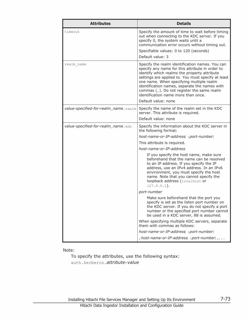
Attributes Details
timeout Specify the amount of time to wait before timingout when connecting to the KDC server. If youspecify 0, the system waits until acommunication error occurs without timing out.
Specifiable values: 0 to 120 (seconds)
Default value: 3
realm_name Specify the realm identification names. You canspecify any name for this attribute in order toidentify which realms the property attributesettings are applied to. You must specify at leastone name. When specifying multiple realmidentification names, separate the names withcommas (,). Do not register the same realmidentification name more than once.
Default value: none
value-specified-for-realm_name.realm Specify the name of the realm set in the KDCserver. This attribute is required.
Default value: none
value-specified-for-realm_name.kdc Specify the information about the KDC server inthe following format:
host-name-or-IP-address[:port-number]This attribute is required.
host-name-or-IP-address
If you specify the host name, make surebeforehand that the name can be resolvedto an IP address. If you specify the IPaddress, use an IPv4 address. In an IPv6environment, you must specify the hostname. Note that you cannot specify theloopback address (localhost or127.0.0.1).
port-number
Make sure beforehand that the port youspecify is set as the listen port number onthe KDC server. If you do not specify a portnumber or the specified port number cannotbe used in a KDC server, 88 is assumed.
When specifying multiple KDC servers, separatethem with commas as follows:
host-name-or-IP-address[:port-number],host-name-or-IP-address[:port-number],...
Note:To specify the attributes, use the following syntax:auth.kerberos.attribute=value
Installing Hitachi File Services Manager and Setting Up Its Environment 7-73Hitachi Data Ingestor Installation and Configuration Guide
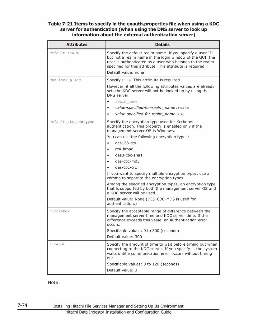
Table 7-21 Items to specify in the exauth.properties file when using a KDCserver for authentication (when using the DNS server to look up
information about the external authentication server)
Attributes Details
default_realm Specify the default realm name. If you specify a user IDbut not a realm name in the login window of the GUI, theuser is authenticated as a user who belongs to the realmspecified for this attribute. This attribute is required.
Default value: none
dns_lookup_kdc Specify true. This attribute is required.
However, if all the following attributes values are alreadyset, the KDC server will not be looked up by using theDNS server.
• realm_name• value-specified-for-realm_name.realm• value-specified-for-realm_name.kdc
default_tkt_enctypes Specify the encryption type used for Kerberosauthentication. This property is enabled only if themanagement server OS is Windows.
You can use the following encryption types:
• aes128-cts
• rc4-hmac
• des3-cbc-sha1
• des-cbc-md5
• des-cbc-crc
If you want to specify multiple encryption types, use acomma to separate the encryption types.
Among the specified encryption types, an encryption typethat is supported by both the management server OS anda KDC server will be used.
Default value: None (DES-CBC-MD5 is used forauthentication.)
clockskew Specify the acceptable range of difference between themanagement server time and KDC server time. If thedifference exceeds this value, an authentication erroroccurs.
Specifiable values: 0 to 300 (seconds)
Default value: 300
timeout Specify the amount of time to wait before timing out whenconnecting to the KDC server. If you specify 0, the systemwaits until a communication error occurs without timingout.
Specifiable values: 0 to 120 (seconds)
Default value: 3
Note:
7-74 Installing Hitachi File Services Manager and Setting Up Its EnvironmentHitachi Data Ingestor Installation and Configuration Guide
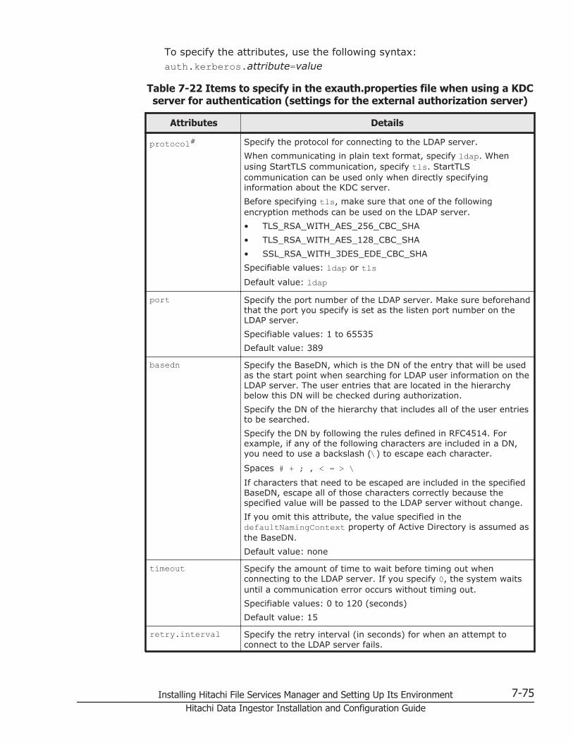
To specify the attributes, use the following syntax:auth.kerberos.attribute=value
Table 7-22 Items to specify in the exauth.properties file when using a KDCserver for authentication (settings for the external authorization server)
Attributes Details
protocol# Specify the protocol for connecting to the LDAP server.
When communicating in plain text format, specify ldap. Whenusing StartTLS communication, specify tls. StartTLScommunication can be used only when directly specifyinginformation about the KDC server.
Before specifying tls, make sure that one of the followingencryption methods can be used on the LDAP server.
• TLS_RSA_WITH_AES_256_CBC_SHA
• TLS_RSA_WITH_AES_128_CBC_SHA
• SSL_RSA_WITH_3DES_EDE_CBC_SHA
Specifiable values: ldap or tlsDefault value: ldap
port Specify the port number of the LDAP server. Make sure beforehandthat the port you specify is set as the listen port number on theLDAP server.
Specifiable values: 1 to 65535
Default value: 389
basedn Specify the BaseDN, which is the DN of the entry that will be usedas the start point when searching for LDAP user information on theLDAP server. The user entries that are located in the hierarchybelow this DN will be checked during authorization.
Specify the DN of the hierarchy that includes all of the user entriesto be searched.
Specify the DN by following the rules defined in RFC4514. Forexample, if any of the following characters are included in a DN,you need to use a backslash (\) to escape each character.
Spaces # + ; , < = > \If characters that need to be escaped are included in the specifiedBaseDN, escape all of those characters correctly because thespecified value will be passed to the LDAP server without change.
If you omit this attribute, the value specified in thedefaultNamingContext property of Active Directory is assumed asthe BaseDN.
Default value: none
timeout Specify the amount of time to wait before timing out whenconnecting to the LDAP server. If you specify 0, the system waitsuntil a communication error occurs without timing out.
Specifiable values: 0 to 120 (seconds)
Default value: 15
retry.interval Specify the retry interval (in seconds) for when an attempt toconnect to the LDAP server fails.
Installing Hitachi File Services Manager and Setting Up Its Environment 7-75Hitachi Data Ingestor Installation and Configuration Guide

Attributes Details
Specifiable values: 1 to 60 (seconds)
Default value: 1
retry.times Specify the number of retries to attempt when an attempt toconnect to the LDAP server fails. If you specify 0, no retries areattempted.
Specifiable values: 0 to 50
Default value: 20
Note:To specify the attributes, use the following syntax:auth.group.realm-name.attribute=value
For realm-name, specify the value specified forauth.kerberos.realm_name-property-value.realm.
#:When communicating by using StartTLS as the protocol for connecting tothe LDAP server, you need to specify the security settings of CommonComponent. For details about specifying security settings in order tocommunicate by using StartTLS, see Setting the security for HitachiCommand Suite Common Component (communication with an LDAPserver) on page 7-83.
Table 7-23 Items to specify in the exauth.properties file when using a KDCserver for authentication (when an external authorization server and
StartTLS are used for communication)
Property Details
auth.ocsp.enable Specify whether or not to verify the validity of an LDAP server'selectronic signature certificate by using an OCSP responder ora CRL when the LDAP server and StartTLS are used forcommunication.
If you want to verify the validity of certificates, specify true.To not verify the validity of certificates, specify false.
Default value: falseauth.ocsp.responderURL
Specify the URL of an OCSP responder if you want to use anOCSP responder that is not the one written in the AIA field ofthe electronic signature certificate to verify the validity of theelectronic signature certificate. If this value is omitted, theOCSP responder written in the AIA field is used.
Default value: None
The following examples show how to specify the properties:
• When directly specifying information about a KDC server (when notlinking to an external authorization server):
auth.server.type=kerberosauth.group.mapping=false
7-76 Installing Hitachi File Services Manager and Setting Up Its EnvironmentHitachi Data Ingestor Installation and Configuration Guide
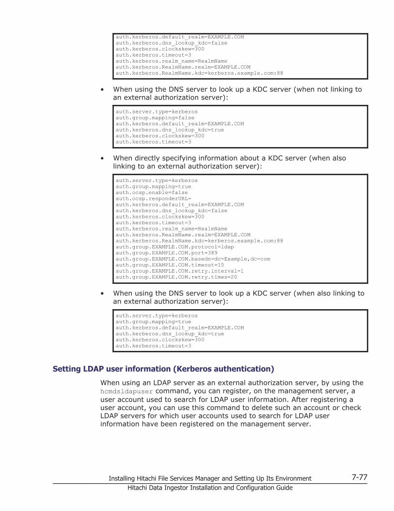
auth.kerberos.default_realm=EXAMPLE.COMauth.kerberos.dns_lookup_kdc=falseauth.kerberos.clockskew=300auth.kerberos.timeout=3auth.kerberos.realm_name=RealmNameauth.kerberos.RealmName.realm=EXAMPLE.COMauth.kerberos.RealmName.kdc=kerberos.example.com:88
• When using the DNS server to look up a KDC server (when not linking toan external authorization server):
auth.server.type=kerberosauth.group.mapping=falseauth.kerberos.default_realm=EXAMPLE.COMauth.kerberos.dns_lookup_kdc=trueauth.kerberos.clockskew=300auth.kerberos.timeout=3
• When directly specifying information about a KDC server (when alsolinking to an external authorization server):
auth.server.type=kerberosauth.group.mapping=trueauth.ocsp.enable=falseauth.ocsp.responderURL=auth.kerberos.default_realm=EXAMPLE.COMauth.kerberos.dns_lookup_kdc=falseauth.kerberos.clockskew=300auth.kerberos.timeout=3auth.kerberos.realm_name=RealmNameauth.kerberos.RealmName.realm=EXAMPLE.COMauth.kerberos.RealmName.kdc=kerberos.example.com:88auth.group.EXAMPLE.COM.protocol=ldapauth.group.EXAMPLE.COM.port=389auth.group.EXAMPLE.COM.basedn=dc=Example,dc=comauth.group.EXAMPLE.COM.timeout=15auth.group.EXAMPLE.COM.retry.interval=1auth.group.EXAMPLE.COM.retry.times=20
• When using the DNS server to look up a KDC server (when also linking toan external authorization server):
auth.server.type=kerberosauth.group.mapping=trueauth.kerberos.default_realm=EXAMPLE.COMauth.kerberos.dns_lookup_kdc=trueauth.kerberos.clockskew=300auth.kerberos.timeout=3
Setting LDAP user information (Kerberos authentication)
When using an LDAP server as an external authorization server, by using thehcmdsldapuser command, you can register, on the management server, auser account used to search for LDAP user information. After registering auser account, you can use this command to delete such an account or checkLDAP servers for which user accounts used to search for LDAP userinformation have been registered on the management server.
Installing Hitachi File Services Manager and Setting Up Its Environment 7-77Hitachi Data Ingestor Installation and Configuration Guide
Registering an account to search for LDAP user information(Kerberos authentication)
Use the hcmdsldapuser command to register a user account used to searchfor LDAP user information.
For a user account used to search for LDAP user information, register a useraccount that satisfies the following conditions:
• The user account is already registered in the LDAP server.
• The user account can bind to the DN specified for auth.group.realm-name.basedn in the exauth.properties file
• The user account can search the attributes for all entries below the DNspecified for auth.group.realm-name.basedn in the exauth.propertiesfile
• The user account can reference the DN specified for auth.group.realm-name.basedn in the exauth.properties file
• The user account can reference the authorization groups that are underthe DN specified for auth.group.realm-name.basedn in theexauth.properties file
• The user account can search the attributes of the authorization groupsthat are under the DN specified for auth.group.realm-name.basedn inthe exauth.properties file and search the attributes of nested groups ofthe authorization groups
The format of the hcmdsldapuser command is as follows:Hitachi-Command-Suite-Common-Component-installation-folder\bin\hcmdsldapuser /set /dn DN-of-user-account-used-to-search-for-LDAP-user-info [/pass password-of-user-account-used-to-search-for-LDAP-user-info] /name realm-name• DN-of-user-account-used-to-search-for-LDAP-user-info
Specify a DN by following the rules defined in RFC4514. For example, ifthe following characters are included in a DN, you need to use abackslash (\) to escape each character.
Spaces # + , ; < = > \• password-of-user-account-used-to-search-for-LDAP-user-info
This is case-sensitive and must exactly match the password registered inthe LDAP server. If you execute the command without specifying the passoption, you will be prompted to enter a password (in the interactivemode, the entered character string is displayed by using replacementcharacters).
• realm-nameIf you directly specify information about a KDC server in theexauth.properties file, specify the value specified forauth.kerberos.default_realm orauth.kerberos.auth.kerberos.realm_name-property-value.realm.
7-78 Installing Hitachi File Services Manager and Setting Up Its EnvironmentHitachi Data Ingestor Installation and Configuration Guide
If you specify the settings in the exauth.properties file to use the DNSserver to look up information about a KDC server, specify the realm nameregistered in the DNS server.
Note:In the LDAP server, you can use double quotation marks (") for the DNand password. In the management server, however, you need to registera user account whose DN and password do not include double quotationmarks.
Important:
¢ You can use the dsquery command provided by Active Directory tocheck the DN of a user. The following example shows how to use thedsquery command to check the DN of the user administrator, andalso shows the execution results:dsquery user -name administrator"CN=administrator,CN=admin,DC=example,DC=com"
¢ If the DN includes commas such ascn=administrator,cn=admin,dc=example,com, specify as follows:hcmdsldapuser /set /dn "cn=administrator,cn=admin,dc=example\,com" /pass administrator_pass /name ServerName
Deleting the account that searches for LDAP user information(Kerberos authentication)
To delete a user account used to search for LDAP user information, executethe following command.Hitachi-Command-Suite-Common-Component-installation-folder\bin\hcmdsldapuser /delete /name realm-name
Checking which LDAP servers have accounts that search for LDAPuser information (Kerberos authentication)
To check the names of LDAP servers for which a user account used to searchfor LDAP user information has been registered on the management server,execute the following command.Hitachi-Command-Suite-Common-Component-installation-folder\bin\hcmdsldapuser /list
Checking the connection status of external authentication and authorizationservers (Kerberos authentication)
By using the hcmdscheckauth command, you can make sure that the externalauthentication server and the external authorization server can be properlyconnected to. If you have specified multiple realm names in theexauth.properties file, perform this operation for each realm.Hitachi-Command-Suite-Common-Component-installation-folder\bin\hcmdscheckauth [/user user-ID /pass password] [/summary]
Installing Hitachi File Services Manager and Setting Up Its Environment 7-79Hitachi Data Ingestor Installation and Configuration Guide

• The user account to be specified for user-ID and password depends onwhether only an external authentication server is linked or an externalauthorization server is also linked to.
When linking to only an external authentication server:Specify a user account that is registered in Hitachi File ServicesManager and whose authentication method has been set to Kerberosauthentication.
When also linking to an external authorization server:Specify a user account that is not registered in Hitachi File ServicesManager.
If you specify a user who belongs to a realm different from the realmname specified for default_realm in the exauth.properties file, specifya character string that contains the realm name for user-ID. If you specifya user who belongs to the realm specified for default_realm in theexauth.properties file, you can omit the realm name. In addition, notethat you cannot specify a user account whose user-ID or password beginswith a forward slash (/).
If you execute the command without specifying the user option or thepass option, you will be prompted to enter a user ID and password (inthe interactive mode, the entered character string is displayed by usingreplacement characters).
• If you execute the command with the summary option specified, theconfirmation message is displayed in summary format.
If you execute the hcmdscheckauth command, the settings in theexauth.properties file, and the connection status of the externalauthentication server and the external authorization server are checked in thefour phases described below. Check results are displayed for each phase.
Phase 1The command verifies that common properties (Table 7-19 Items tospecify in the exauth.properties file when using a KDC server forauthentication (common items) on page 7-71) have been correctlyspecified in the exauth.properties file.
Phase 2The command verifies that the properties for the external authenticationserver (Table 7-20 Items to specify in the exauth.properties file whenusing a KDC server for authentication (when directly specifyinginformation about the external authentication server) on page 7-72 andTable 7-21 Items to specify in the exauth.properties file when using aKDC server for authentication (when using the DNS server to look upinformation about the external authentication server) on page 7-74) andproperties for the external authorization server (Table 7-22 Items tospecify in the exauth.properties file when using a KDC server forauthentication (settings for the external authorization server) on page7-75 and Table 7-23 Items to specify in the exauth.properties file whenusing a KDC server for authentication (when an external authorization
7-80 Installing Hitachi File Services Manager and Setting Up Its EnvironmentHitachi Data Ingestor Installation and Configuration Guide

server and StartTLS are used for communication) on page 7-76) havebeen correctly specified in the exauth.properties file.
Phase 3The command verifies that the external authentication server can beconnected to.
Phase 4If an external authorization server is also linked to, the command verifiesthat the external authorization server can be connected to andauthorization groups can be searched.
When a phase finishes normally, the following message is displayed:
KAPM15004-I The result of the configuration check of Phase X was normal.
Note: X is the phase number.
Encryption types for Kerberos authentication
In Hitachi File Services Manager, the encryption types listed below can beused for Kerberos authentication. Configure the KDC server so that one of thefollowing encryption types can be used.
• AES128-CTS-HMAC-SHA1-96
• RC4-HMAC
• DES3-CBC-SHA1
• DES-CBC-CRC
• DES-CBC-MD5
Note that, if the OS of the external authentication server is Windows Server2008, Windows Server 2008 R2, Windows Server 2012, or Windows Server2012 R2 and the environment meets both of the following conditions, userauthentication might not work properly:
• The domain functional level on the external authentication server is set toWindows Server 2003 or Windows 2000.
• The OS of the management server supports AES128-CTS encryption.
For example, even if the domain functional level of Active Directory is set toWindows Server 2003 or Windows 2000, in either of the following cases,the corresponding user cannot be authenticated via Active Directory:
• A user existing before an Active Directory system was built is migrated tothe Active Directory system, which has a domain functional level ofWindows Server 2003, and then the user's password is changed.
• An Active Directory system built in Windows Server 2003 is migrated toan Active Directory system built in Windows Server 2008, WindowsServer 2012 with a domain functional level of Windows Server 2003,and then a user's password is changed.
Installing Hitachi File Services Manager and Setting Up Its Environment 7-81Hitachi Data Ingestor Installation and Configuration Guide

In this case, change the default_tkt_enctypes property setting in theexauth.properties file as follows:
auth.kerberos.default_tkt_enctypes=rc4-hmac
Connecting to Device Manager to manage user accountsIf Hitachi File Services Manager is linked with Device Manager, Hitachi FileServices Manager must connect to Device Manager to manage user accounts.If you install Hitachi File Services Manager on a management server on whichDevice Manager version 8.0 or later has already been installed, or if youinstall Hitachi File Services Manager and Device Manager on differentmachines, specify settings so that Hitachi File Services Manager connects toDevice Manager to manage user accounts.
If you install Hitachi File Services Manager on a management server on whichDevice Manager version 8.0 or later has already been installed
To specify settings so that Hitachi File Services Manager connects to DeviceManager to manage user accounts, perform the following procedure:
1. On the management server, execute the following command to set theinformation required to connect to Device Manager:
Hitachi-Command-Suite-Common-Component-installation-folder\bin\hcmdsprmset /host IP-address-or-host-name-of-the-management-server /port Device-Manager-port-number [/sslport Device-Manager-port-number-for-SSL-connection]
2. Restart Hitachi File Services Manager and Device Manager.For details about how to start and stop Hitachi File Services Manager, seeStarting and stopping Hitachi File Services Manager on page 7-31. Torestart Device Manager, ask the Device Manager system administrator.
If you install Hitachi File Services Manager and Device Manager on differentmachines
To specify settings so that Hitachi File Services Manager connects to DeviceManager to manage user accounts, perform the following procedure:
Also note that the procedure for changing the management server differsdepending on the order in which Hitachi File Services Manager and DeviceManager were installed.
Hitachi File Services Manager is installed after Device Manager isoperational or both Hitachi File Services Manager and DeviceManager are installed at the same time
1. Execute the following command on the management server on whichHitachi File Services Manager is installed to set the information requiredto connect the server on which Device Manager is installed:
7-82 Installing Hitachi File Services Manager and Setting Up Its EnvironmentHitachi Data Ingestor Installation and Configuration Guide

Hitachi-Command-Suite-Common-Component-installation-folder\bin\hcmdsprmset /host Device-Manager-IP-address-or-host-name /port port-number [/sslport SSL-port-number]
2. Restart Hitachi File Services Manager.For details about how to start and stop Hitachi File Services Manager, seeStarting and stopping Hitachi File Services Manager on page 7-31.
Device Manager is installed after Hitachi File Services Manager isoperational
1. Execute the following command on the management server on whichHitachi File Services Manager is installed to output the authentication datafor Hitachi File Services Manager:
Hitachi-Command-Suite-Common-Component-installation-folder\bin\hcmdsauthmove /export /datapath absolute-path-of-the-folder-to-which-Hitachi-File-Services-Manager-authentication-data-is-output
2. Ask the Device Manager system administrator to migrate the Hitachi FileServices Manager authentication data.
3. Execute the following command on the management server on whichHitachi File Services Manager is installed to set the information requiredto connect the server on which Device Manager is installed:
Hitachi-Command-Suite-Common-Component-installation-folder\bin\hcmdsprmset /host Device-Manager-IP-address-or-host-name /port port-number [/sslport SSL-port-number]
4. Restart Hitachi File Services Manager and Device Manager.For details about how to start and stop Hitachi File Services Manager, seeStarting and stopping Hitachi File Services Manager on page 7-31. Torestart Device Manager, ask the Device Manager system administrator.
Setting the security for Hitachi Command Suite Common Component(communication with an LDAP server)
In Hitachi File Services Manager, when performing user authentication orauthorization by linking with an LDAP server, you can encrypt networktransmissions between Hitachi File Services Manager and the LDAP server byusing StartTLS. To use StartTLS to protect communications between themanagement server and LDAP server, you need to perform the followingoperations:
• Obtain a certificate for the LDAP server
• Import the certificate into the truststore file
To encrypt network transmissions between Hitachi File Services Manager andan LDAP server by using StartTLS, you also need to set up theexauth.properties file.
Note:
Installing Hitachi File Services Manager and Setting Up Its Environment 7-83Hitachi Data Ingestor Installation and Configuration Guide

The CN (the CN in the Subject section) of the certificate for the LDAPserver must be the same as the value specified for the following attributein the exauth.properties file.
If the authentication method is LDAP:auth.ldap.value-specified-for-auth.server.name.host
If the authentication method is RADIUS and an external authorizationserver is also linked to:
If the external authentication server and the external authorizationserver are running on the same computer:auth.radius.value-specified-for-auth.server.name.hostIf the external authentication server and the external authorizationserver are running on different computers:auth.group.domain-name.host
If the authentication method is Kerberos and an external authorizationserver is also linked to:
auth.kerberos.value-specified-for-auth.kerberos.realm_name.kdc
Obtaining a certificate for an LDAP server
Obtain a server certificate for the LDAP server that communicates with themanagement server. For details, see the documentation for the LDAP serveryou use.
If you use a digitally-signed certificate issued by a certificate authority, makesure that all certificates issued by authorities between the certificate authoritythat issued the server certificate and the root certificate authority must forma certificate chain. To use a CRL distribution point (CDP) to verify the validityof the digitally-signed certificate, you must obtain a certificate whose AIA andCDP fields do not contain URLs that begin with ldap.
If you have obtained a certificate for the LDAP server from a well-known CA,the CA certificate might already be set up in the standard truststorereferenced by Common Component. Execute the command below to checkthis. If a registered CA certificate is used to authenticate LDAP servercertificates, you do not need to set up the truststore described in Importingan LDAP server certificate to the truststore file on page 7-85.Hitachi-Command-Suite-Common-Component-installation-folder\bin\hcmdskeytool -list -v -keystore truststore-file-name -storepass password-to-access-the-truststore
• For the keystore option, specify the truststore file to be referenced.Hitachi-Command-Suite-Common-Component-installation-folder\jdk\jre\lib\security\cacerts
• For the storepass option, specify the password used to reference thetruststore cacerts. The default is changeit.
Note:
7-84 Installing Hitachi File Services Manager and Setting Up Its EnvironmentHitachi Data Ingestor Installation and Configuration Guide

Do not import and use your own certificate into the truststore cacertsbecause that truststore is updated when Common Component isupgraded.
Importing an LDAP server certificate to the truststore file
Import the certificate for the LDAP server into the truststore used byCommon Component. We recommend importing the LDAP server certificateinto ldapcacerts. The certificate can be imported to jssecacerts, evenwhen the certificate is shared with other programs. If no truststore file exists,create a truststore file.Hitachi-Command-Suite-Common-Component-installation-folder\conf\sec\ldapcacertsHitachi-Command-Suite-Common-Component-installation-folder\jdk\jre\lib\security\jssecacertsTo create a truststore file, import a certificate, and check the contents, usethe hcmdskeytool utility.
To create a truststore file and import a certificate, execute the followingcommand:Hitachi-Command-Suite-Common-Component-installation-folder\bin\hcmdskeytool -import -alias unique-name-in-the-truststore -file certificate-file-name -keystore truststore-file-name -storepass password-to-access-the-truststore
• For the alias option, specify the name used to identify the certificate inthe truststore.
• For the file option, specify the certificate file.
• For the keystore option, specify the truststore file to be registered andcreated.
• For the storepass option, specify the password used to access thetruststore.
To view the contents of the truststore, execute the following command:Hitachi-Command-Suite-Common-Component-installation-folder\bin\hcmdskeytool -list -v -keystore truststore-file-name -storepass password-to-access-the-truststore
• For the keystore option, specify the truststore file to be checked.
• For the storepass option, specify the password used to access thetruststore.
Note that, to apply the truststore, you need to restart Hitachi File ServicesManager by using the following procedure:
1. Stop Hitachi File Services Manager.For details on how to do this, see Stopping Hitachi File Services Manageron page 7-33.
2. Start Hitachi File Services Manager.For details on how to do this, see Starting Hitachi File Services Manageron page 7-32.
Installing Hitachi File Services Manager and Setting Up Its Environment 7-85Hitachi Data Ingestor Installation and Configuration Guide
Notes:
¢ If there are multiple certificate files, import certificate files byspecifying alias names not used in the truststore.
¢ Note the following when you use the hcmdskeytool utility to specify aunique name in the truststore, the truststore file name, and thepassword:- Do not use the following symbols in the file name: : , ; * ? " <> |- Specify the file name as a character string of no more than 255bytes.- Do not include double quotation marks (") in the unique name inthe truststore or the password.
Setting up the Hitachi File Services Manager environmentThe system administrator can set up or change Hitachi File Services Managerenvironment by editing the configuration files.
If the management server is being used in a cluster configuration, thesettings must be same on both the executing node and standby node.
This section describes how the system administrator can set up Hitachi FileServices Manager environment.
Changing the log file settingsThe system administrator can change settings of Hitachi File ServicesManager message log, such as maximum capacity or output level, by editingthe property file.
To change the log file settings:
1. Edit the property file (user.properties) to change the log file settings.
The property file is located in the following folder:Hitachi-File-Services-Manager-installation-folder\conf\
2. Stop and then restart Hitachi File Services Manager and Hitachi CommandSuite Common Component.For details on how to do this, see Starting and stopping Hitachi FileServices Manager on page 7-31.
The following table lists the properties related to log file settings.
Table 7-24 Properties in the user.properties file related to log file settings
Property Description
hnasm.common.logger.loglevel Specify the output level of the Hitachi FileServices Manager message log.
Specifiable value#1
7-86 Installing Hitachi File Services Manager and Setting Up Its EnvironmentHitachi Data Ingestor Installation and Configuration Guide

Property Description
-1, 0, 10, 20, or 30Default value
20If you specify an invalid value, 20 is assumed.
hnasm.common.logger.syslog.loglevel
Specify the output level of the Hitachi FileServices Manager event log.
Specifiable value#1
-1, 0, 10, 20, or 30Default value
0If you specify an invalid value, 0 is assumed.
hnasm.common.logger.maxfilenumber
Specify the maximum number of backups of theHitachi File Services Manager message log.
Specifiable value#2
1 to 16Default value
10If you specify an invalid value, 10 is assumed.
hnasm.common.logger.maxfilesize Specify the maximum capacity of the Hitachi FileServices Manager message log in bytes.
Specifiable value#2
4096 to 2147483647Default value
2097152If you specify an invalid value, 2097152 isassumed.
#1: The meaning of the values is listed below. Note that we recommend thatyou use the default value.
• -1: Nothing is output.
• 0: System information (start and stop, significant errors, etc.) is output.
• 10: System information and error information are output.
• 20: System information, error information, and execution historyinformation are output.
• 30: Debug information is output.
#2: We recommend that you set a value equal to or larger than the defaultvalue.
The following shows an example of the coding in the user.properties file:
hnasm.common.logger.loglevel=20hnasm.common.logger.syslog.loglevel=0
Installing Hitachi File Services Manager and Setting Up Its Environment 7-87Hitachi Data Ingestor Installation and Configuration Guide

hnasm.common.logger.maxfilenumber=10hnasm.common.logger.maxfilesize=2097152
Changing the update setting of the license informationThe system administrator can edit the property file to specify whether toautomatically update the license information every time it is displayed in theLicense Settings subwindow.
To change the update setting of the license information:
1. Edit the property file (user.properties) to change the update setting ofthe license information.The property file is located in the following folder:Hitachi-File-Services-Manager-installation-folder\conf\
2. Stop and then restart Hitachi File Services Manager and Hitachi CommandSuite Common Component.For details on how to stop and start Hitachi File Services Manager andHitachi Command Suite Common Component, see Starting and stoppingHitachi File Services Manager on page 7-31.
The following table describes the property used to change the update settingof the license information.
Table 7-25 Properties in the user.properties file used for changing theupdate setting of the license information
Property Description
hnasm.model.refresh.screen.license
Specifies whether to automatically update thelicense information every time it is displayed.
trueSpecify this to enable automatic informationupdates.
falseSpecify this to disable automatic informationupdates.
The default setting is true. If the specified valueis neither of the above two values, true will beassumed.
The following shows an example of the coding in the user.properties file:
...hnasm.model.refresh.screen.license=true...
7-88 Installing Hitachi File Services Manager and Setting Up Its EnvironmentHitachi Data Ingestor Installation and Configuration Guide

Changing the port numbers used by Hitachi Command Suite CommonComponent
The system administrator can edit the configuration files to change the portnumbers used by Hitachi Command Suite Common Component.
The following table lists the port numbers for Hitachi Command SuiteCommon Component that can be changed.
Table 7-26 Port numbers for Hitachi Command Suite Common Componentthat can be changed
Default portnumber Description
23015/tcp Used for accessing the HBase Storage Mgmt Web Service whencommunicating with management clients.
This port is also used when SSL is enabled. If you want to permitonly SSL communication, set up a firewall.
23016/tcp Used for accessing the HBase Storage Mgmt Web Service whenperforming SSL communication with management clients.
23017/tcp Used internally for Common Component communication(communication with the Web server).
23018/tcp Used internally for Common Component communication (receiving atermination message from the Web server).
23025/tcp Used internally for Common Component communication(communication with the Web server).
23026/tcp Used internally for Common Component communication (receiving atermination message from the Web server).
23031/tcp Used internally for Common Component communication (singlesign-on) if the OS of the management server is Windows.
23032/tcp Used internally for Common Component communication (HiRDB).
To change a port number for Hitachi Command Suite CommonComponent after installing Hitachi File Services Manager:
1. Stop the services of the HiCommand products whose versions are earlierthan 5.7.This step is necessary only if HiCommand products whose versions areearlier than 5.7 are installed. For details on how to stop the service of aHiCommand product, see the documentation for that product.
2. Stop Hitachi File Services Manager and Hitachi Command Suite CommonComponent.For details on how to do this, see Starting and stopping Hitachi FileServices Manager on page 7-31.
3. Edit the configuration files for Hitachi Command Suite CommonComponent to change the port number.The method used to change the port number depends on the portnumber.
Installing Hitachi File Services Manager and Setting Up Its Environment 7-89Hitachi Data Ingestor Installation and Configuration Guide

Table 7-27 Port number settings files for Hitachi Command SuiteCommon Component
Default port number Settings files Location
23015/tcp Hitachi-Command-Suite-Common-Component-installation-folder\httpsd\conf\httpsd.conf
Listen
Hitachi-Command-Suite-Common-Component-installation-folder\conf\hsso.conf
hsso.hostport
23016/tcp Hitachi-Command-Suite-Common-Component-installation-folder\httpsd\conf\httpsd.conf
• VirtualHosthost-name:port-number
• Listen#
23017/tcp Hitachi-Command-Suite-Common-Component-installation-folder\CC\web\redirector\workers.properties
worker.worker1.port
Hitachi-Command-Suite-Common-Component-installation-folder\CC\web\containers\HiCommand\usrconf\usrconf.properties
webserver.connector.ajp13.port
23018/tcp Hitachi-Command-Suite-Common-Component-installation-folder\CC\web\containers\HiCommand\usrconf\usrconf.properties
webserver.shutdown.port
23025/tcp Hitachi-Command-Suite-Common-Component-installation-folder\CC\web\redirector\workers.properties
worker.worker5.port
Hitachi-Command-Suite-Common-Component-installation-folder\CC\web\containers\HiCommand\usrconf\usrconf.properties
webserver.connector.ajp13.port
23026/tcp Hitachi-Command-Suite-Common-Component-installation-folder\CC\web\containers\HiCommand\usrconf\usrconf.properties
webserver.shutdown.port
23031/tcp Hitachi-Command-Suite-Common-Component-installation-folder\httpsd\conf\hsso_httpsd.conf
Listen127.0.0.1:port-number
23032/tcp Hitachi-Command-Suite-Common-Component-installation-folder\HDB\CONF\emb\HiRDB.ini
PDNAMEPORT
Hitachi-Command-Suite-Common-Component-installation-folder\HDB\CONF\pdsys
pd_name_port
7-90 Installing Hitachi File Services Manager and Setting Up Its EnvironmentHitachi Data Ingestor Installation and Configuration Guide
Default port number Settings files Location
Hitachi-Command-Suite-Common-Component-installation-folder\database\work\def_pdsys
pd_name_port
#1Even when SSL is enabled for accessing HBase Storage Mgmt WebService, 23015/tcp is used for internal communication. Therefore, youmust not delete or comment out the Listen 23015 line.
4. Start Hitachi File Services Manager and Hitachi Command Suite CommonComponent.For details on how to do this, see Starting and stopping Hitachi FileServices Manager on page 7-31.
5. If you stopped services in step 1, start them.This step is necessary only if HiCommand products whose versions areearlier than 5.7 are installed. For details on how to start the service of aHiCommand product, see the documentation for that product.
6. If you change the following port numbers, you need to change the URLsof the management server:
¢ 23015/tcp (used for accessing HBase Storage Mgmt Web Service)You need to change the URLs if you use non-SSL for communicationbetween the management server and management clients.
¢ 23016/tcp (used for accessing SSL HBase Storage Mgmt Web Service)You need to change the URLs if you use SSL for communicationbetween the management server and management clients.
For details on how to change the URLs of the management server, see theDevice Manager documentation.Note that you might not need to change the URLs depending on thenetwork environment between the management server and managementclients, such as an environment that has a firewall configured.
Configuring SSLTo protect communication between the management server and clients usingencryption, the system administrator can set up SSL on the managementserver. HBase Storage Mgmt Web Service uses the public key cryptosystemfor encryption.
The following explains the tasks to perform when configuring SSL on themanagement server and how to disable the SSL setting.
Setting up SSL
When you set up SSL, you need to create a private key and a certificate. Youalso need to specify in the httpsd.conf file where they are stored. There aretwo types of certificates:
Installing Hitachi File Services Manager and Setting Up Its Environment 7-91Hitachi Data Ingestor Installation and Configuration Guide

• Self-signed certificateA certificate signed by the user who issued the certificate. Users cancreate this type of certificate by themselves. We recommend that self-signed certificates be used only for testing encrypted communication.
• CA-issued certificateA certificate signed by the trusted CA. This type of certificate enablesimproved security over a self-signed certificate.
To set up SSL using a self-signed certificate:
1. On the management server, execute the hcmdsssltool command tocreate a private key, a certificate signing request (CSR), and a self-signedcertificate.
Hitachi-Command-Suite-Common-Component-installation-folder\bin\hcmdsssltool /key private-key-file /csr certificate-signing-request-file /cert self-signed-certificate-file /certtext contents-of-a-self-signed-certificate [/validity number-of-valid-days] [/dname DN] [/sigalg signature-algorithm]
¢ For the key option, specify the path to the location to which a privatekey will be output. The size of a private key is 2,048 bits (fixed).
¢ For the csr option, specify the path to the location to which thecertificate signing request will be output.
¢ For the cert option, specify the path to the location to which the self-signed certificate will be output.
¢ For the certtext option, specify the path to the location to which thecontents of the self-signed certificate will be output in text format.
¢ For the validity option, specify the number of days during which theself-signed certificate is valid. If this option is omitted, the validperiod is set to 3,650 days.
¢ For the dname option, specify the DN to be included in the self-signedcertificate and certificate signing request. If you execute thecommand without specifying this option, you will be prompted tospecify the DN.To specify the DN, combine each attribute type with thecorresponding attribute value into one attribute by using an equal sign(=), and then specify the attributes by separating each by a comma.
For the DN, you cannot specify a double quotation mark (") orbackslash (\). In addition, specify each attribute value as defined byRFC2253. For example, if the specified DN includes any of thefollowing characters, escape each of them by using a backslash (\).
A space at the beginning of or at the end of the DNA hash mark (#) at the beginning of the DN
A plus sign (+), comma (,), semicolon (;), left angle bracket (<),equal sign (=), or right angle bracket (>)
The following table lists and describes the attribute types and valuesspecified for the DN.
7-92 Installing Hitachi File Services Manager and Setting Up Its EnvironmentHitachi Data Ingestor Installation and Configuration Guide

Table 7-28 Attribute types and values specified for the DN
Attributetype
Full name of attributetype Attribute value
CN Common Name Specify the host name of themanagement server (HBase StorageMgmt Web Service). This attribute isrequired.
Specify the host name used whenconnecting to the management server(HBase Storage Mgmt Web Service ofCommon Component) from themanagement client. You can alsospecify the host name in FQDN format.If the management server is running ina cluster configuration, specify thelogical host name.
OU Organizational Unit Name Specify the name of the organizationalunit.
O Organization Name Specify the organizational name. Thisattribute is required.
L Locality Name Specify the name of the city, town, orother locality.
ST State or Province Name Specify the name of the state orprovince.
C Country Name Specify the two-letter country code.
¢ Specify a signature algorithm for the sigalg option. You can specifySHA256withRSA, SHA1withRSA, or MD5withRSA. If you omit thisspecification, SHA256withRSA is used as the signature algorithm.
Caution: When you execute the hcmdsssltool command, if a file withthe same name already exists in the output location, the existing file willbe overwritten. Therefore, when you recreate a private key, certificatesigning request, or self-signed certificate, we recommend you to outputthem to a directory other than existing storage directories.A certificate signing request and self-signed certificate are created with aprivate key size of 2,048 bits. The certificate signing request is created inPEM format.The following is an example of executing commands to create a privatekey, a certificate signing request, and a self-signed certificate:
¢ Private key file: httpsdkey.pem¢ Certificate signing request file: httpd.csr¢ Self-signed certificate file: httpsd.pem¢ Contents of a self-signed certificate: httpsdpem.txt¢ Number of valid days: 365 days
¢ DN
Installing Hitachi File Services Manager and Setting Up Its Environment 7-93Hitachi Data Ingestor Installation and Configuration Guide

CN: hfsm-nagpurOU: WebsiteO: HITACHIL: New YorkST: WashingtonC: US
"C:\Program Files (x86)\HiCommand\Base\bin\hcmdsssltool" /key C:\temp\httpsdkey.pem /csr C:\temp\httpsd.csr /cert C:\temp\httpsd.pem /certtext C:\temp\httpsdpem.txt /validity 365 /dname "CN=hfsm-nagpur,OU=Website,O=HITACHI,L=New York,ST=Washington,C=US"
2. Copy the private key file and certificate file to an appropriate folder.We recommend that you copy them to the following folder:Hitachi-Command-Suite-Common-Component-installation-folder\httpsd\conf\ssl\server
3. Edit the httpsd.conf file. Specify information such as the paths to theprivate key and the server certificate in each directive of the httpsd.conffile, and then delete the hash mark (#) at the beginning of the line.
The httpsd.conf file is located in the following folder:Hitachi-Command-Suite-Common-Component-installation-folder\httpsd\conf\The following is an example of the httpsd.conf file format.
ServerName logical-host-name...Listen 23015#Listen [::]:23015SSLDisable
SSLSessionCacheSize 0Listen 23016#Listen [::]:23016<VirtualHost *:port-number> ServerName logical-host-name SSLEnable SSLProtocol SSLv3 TLSv1 SSLRequiredCiphers AES256-SHA:AES128-SHA:DES-CBC3-SHA SSLRequireSSL SSLCertificateFile server-certificate-for-Common-Component SSLCertificateKeyFile private-key-for-Common-Component SSLCACertificateFile server-certificate-of-certificate-authority SSLSessionCacheTimeout 3600</VirtualHost>
¢ For the ServerName directives in the following locations, specify thehost name that you specified for Common Name in the certificatesigning request. Note that host names are case sensitive.- ServerName at the beginning of the httpsd.conf file
- ServerName enclosed by <VirtualHost> and </VirtualHost>¢ If you are using an IPv6 environment, remove the hash mark (#) at
the beginning of the lines #Listen [::]:23015 and #Listen [::]:23016.
7-94 Installing Hitachi File Services Manager and Setting Up Its EnvironmentHitachi Data Ingestor Installation and Configuration Guide

¢ For <VirtualHost>, usually specify an asterisk (*), although you canalso specify a host name.
¢ We recommend that you do not specify "SSLv3" in the SSLProtocoldirective, as the SSL 3.0 protocol has a security flaw.
¢ For operation in advanced security mode, add the SSLProtocol andSSLRequiredCiphers directives to limit the cipher strength.
Note that when using TLS v1.1 or TLS v1.2 for communication, alsospecify the protocol, encryption algorithm, and hash algorithm for thedirectives above. Also, edit the security settings of the browser for themachine used to access management servers such as managementconsoles. To edit the settings, in Tools in Internet Explorer, selectInternet Options, and in the Advanced tab, edit the settings sothat TLS 1.1 and TLS 1.2 can be used. The following shows what youcan also specify for the SSLProtocol and SSLRequiredCiphersdirectives.
Table 7-29 Information that can also be specified for theSSLProtocol and SSLRequiredCiphers directives
Target directive Information to be specified
SSLProtocol Specify the protocol to be used.
TLSv11Specify this when using TLS v1.1.
TLSv12Specify this when using TLS v1.2.
SSLRequiredCiphers Specify the encryption algorithm and hashalgorithm to be used.
AES256-SHA256Specify this when using AES256 as theencryption algorithm and SHA256 as thehash algorithm.
AES128-SHA256Specify this when using AES128 as theencryption algorithm and SHA256 as thehash algorithm.
The following is an example of the specifications after the additionalinformation was specified:
SSLProtocol TLSv1 TLSv11 TLSv12SSLRequiredCiphers AES256-SHA:AES128-SHA:DES-CBC3-SHA:AES256-SHA256:AES128-SHA256
¢ For the SSLCertificateFile directive, specify the absolute path tothe signed server certificate sent back from the certificate authority orthe absolute path to the self-signed certificate file.
¢ For the SSLCertificateKeyFile directive, specify the absolute pathto the private key file for Common Component.Do not specify a symbolic link and junction for the path.
Installing Hitachi File Services Manager and Setting Up Its Environment 7-95Hitachi Data Ingestor Installation and Configuration Guide

¢ For the SSLCACertificateFile directive, if you use a servercertificate issued by a certificate authority, specify the absolute pathto the server certificate. Multiple server certificates can be containedin one file by chaining multiple PEM format server certificates by usinga text editor. Note that you must not specify a symbolic link orjunction for the path.
Caution: The non-SSL port (default: 23015) is used for communicationwithin Device Manager even if SSL is enabled. Do not delete or commentout the line Listen 23015 (this line is for when the default port is used)because the line is the setting for the non-SSL port.The following shows an example of specifying settings in the httpsd.conffile. The lines beginning with a hash mark (#) are comment lines.
ServerName www.example.com...Listen 23015#Listen [::]:23015SSLDisable
SSLSessionCacheSize 0Listen 23016#Listen [::]:23016<VirtualHost *:23016> ServerName hfsm-nagpur SSLEnable SSLProtocol TLSv1 SSLRequiredCiphers AES256-SHA:AES128-SHA:DES-CBC3-SHA SSLRequireSSL SSLCertificateFile "C:/Program Files (x86)/HiCommand/Base/httpsd/conf/ssl/server/httpsd.pem" SSLCertificateKeyFile "C:/Program Files (x86)/HiCommand/Base/httpsd/conf/ssl/server/httpsdkey.pem"# SSLCACertificateFile "C:/Program Files (x86)/HiCommand/Base/httpsd/conf/ssl/cacert/anycert.pem" SSLSessionCacheTimeout 3600</VirtualHost>
4. Change the URL of the management server.This step is necessary if both Hitachi File Services Manager and DeviceManager are installed on the same management server. For details abouthow to change the URL of the management server, see the applicableDevice Manager manual.
5. Stop and then restart Hitachi File Services Manager and Hitachi CommandSuite Common Component.For details on how to do this, see Starting and stopping Hitachi FileServices Manager on page 7-31.
Disabling the SSL settings
To disable SSL:
1. In the httpsd.conf file, add a hash mark (#) to the beginning of eachSSL directive showing information such as paths to the private key andthe server certificate, so that they are commented out.Edit the httpsd.conf file to disable SSL.
7-96 Installing Hitachi File Services Manager and Setting Up Its EnvironmentHitachi Data Ingestor Installation and Configuration Guide
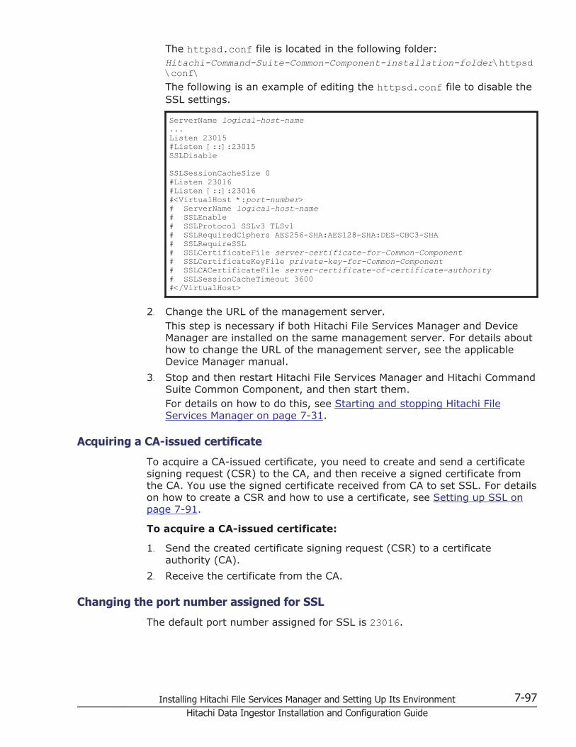
The httpsd.conf file is located in the following folder:Hitachi-Command-Suite-Common-Component-installation-folder\httpsd\conf\The following is an example of editing the httpsd.conf file to disable theSSL settings.
ServerName logical-host-name...Listen 23015#Listen [::]:23015SSLDisable
SSLSessionCacheSize 0#Listen 23016#Listen [::]:23016#<VirtualHost *:port-number># ServerName logical-host-name# SSLEnable# SSLProtocol SSLv3 TLSv1# SSLRequiredCiphers AES256-SHA:AES128-SHA:DES-CBC3-SHA# SSLRequireSSL# SSLCertificateFile server-certificate-for-Common-Component# SSLCertificateKeyFile private-key-for-Common-Component# SSLCACertificateFile server-certificate-of-certificate-authority# SSLSessionCacheTimeout 3600#</VirtualHost>
2. Change the URL of the management server.This step is necessary if both Hitachi File Services Manager and DeviceManager are installed on the same management server. For details abouthow to change the URL of the management server, see the applicableDevice Manager manual.
3. Stop and then restart Hitachi File Services Manager and Hitachi CommandSuite Common Component, and then start them.For details on how to do this, see Starting and stopping Hitachi FileServices Manager on page 7-31.
Acquiring a CA-issued certificate
To acquire a CA-issued certificate, you need to create and send a certificatesigning request (CSR) to the CA, and then receive a signed certificate fromthe CA. You use the signed certificate received from CA to set SSL. For detailson how to create a CSR and how to use a certificate, see Setting up SSL onpage 7-91.
To acquire a CA-issued certificate:
1. Send the created certificate signing request (CSR) to a certificateauthority (CA).
2. Receive the certificate from the CA.
Changing the port number assigned for SSL
The default port number assigned for SSL is 23016.
Installing Hitachi File Services Manager and Setting Up Its Environment 7-97Hitachi Data Ingestor Installation and Configuration Guide

For details on how to change the default SSL port number (23016), seeChanging the port numbers used by Hitachi Command Suite CommonComponent on page 7-89.
Importing the required SSL certificate for communication betweenthe node and management server
The system administrator must import the SSL certificate to the managementserver because communication between the management server and a nodeis performed using SSL.
Normally, the SSL certificate is imported automatically during installation ofHitachi File Services Manager. However, if a password has been set for themanagement server keystore file (jssecacerts), you must manually importthe SSL certificate after installing Hitachi File Services Manager.
To manually import the SSL certificate to the management server:
1. Execute the following command to check whether the SSL certificate hasbeen imported to the management server:
Hitachi-Command-Suite-Common-Component-installation-folder\bin\hcmdskeytool -list -alias hfsm -file -keystore Hitachi-Command-Suite-Common-Component-installation-folder\jdk\jre\lib\security\jssecacerts
After executing the command, you will be prompted to enter thepassword. Enter the keystore password for the management server.If the specified alias (hfsm) does not exist, proceed to the next step.
If information for the certificate is displayed, the certificate has alreadybeen imported. The following steps are unnecessary.
2. Execute the following command to import the SSL certificate to themanagement server:
Hitachi-Command-Suite-Common-Component-installation-folder\bin\hcmdskeytool -import -trustcacerts -alias hfsm -file Hitachi-File-Services-Manager-installation-folder\cert\cacert2.cer -keystore Hitachi-Command-Suite-Common-Component-installation-folder\jdk\jre\lib\security\jssecacerts
After executing the command, you will be prompted to enter thepassword. Enter the keystore password for the management server.
Configuring the warning bannerAs one security solutions, the system administrator can enable an optionalmessage (warning banner) to be displayed in the Login window of Hitachi FileServices Manager. Issuing a warning beforehand to third parties that mightattempt unauthorized accesses can help reduce the risk of problems such asdata corruption or information leakage.
If you register the same message in different languages, the message can beswitched automatically to suit the locale of the Web browser on themanagement console.
7-98 Installing Hitachi File Services Manager and Setting Up Its EnvironmentHitachi Data Ingestor Installation and Configuration Guide

You can use one of the following methods to register a warning banner:
• Using commands
• Using the GUI
This section describes how to use commands to register and removemessages.
Creating a message file
In a message file, in addition to the text of the message, you can use HTMLtags to change font attributes, or to place line breaks in desired locations.
Unicode (UTF-8) characters can be used. A message can contain no morethan 1,000 characters, including HTML tags (line breaks are also counted inthe number of characters). To display a character used in HTML tags, such asa left angle bracket (<), right angle bracket (>), ampersand (&), singlequotation mark (') or double quotation mark ("), use the HTML escapesequence. For example, to display an ampersand (&) in a message, write& in the message file.
The following shows an example of a message:
<center><b>Warning Notice!</b></center>This is a {Company Name Here} computer system, which may be accessed and used only for authorized {Company Name Here} business by authorized personnel. Unauthorized access or use of this computer system may subject violators to criminal, civil, and/or administrative action. <br>All information on this computer system may be intercepted, recorded, read, copied, and disclosed by and to authorized personnel for official purposes, including criminal investigations. Such information includes sensitive data encrypted to comply with confidentiality and privacy requirements. Access or use of this computer system by any person, whether authorized or unauthorized, constitutes consent to these terms. There is no right of privacy in this system.
Note that when you register a message, Hitachi File Services Manager doesnot check or correct the HTML syntax. Therefore you must make sure thatyou use valid HTML syntax when you edit message files. If there is a problemwith HTML syntax in a message, the message might not be displayed in theLogin window correctly.
Reference note:Sample message files in English (bannermsg.txt) and Japanese(bannermsg_ja.txt) are stored in the following folder on themanagement server:Hitachi-Command-Suite-Common-Component-installation-folder\sample\resource\These sample files are overwritten whenever Hitachi Command SuiteCommon Component is installed. If you want to use sample files, firstcopy them to another folder.
Registering a message
Use the hcmdsbanner command to register the message you created. IfHitachi Command Suite products that support the warning banner function
Installing Hitachi File Services Manager and Setting Up Its Environment 7-99Hitachi Data Ingestor Installation and Configuration Guide

have been installed on the management server, the registered message isalso displayed in the Login window of those products.
To register a message, you need to log in with an account that hasAdministrator permissions.
To register a message:
1. Execute the following command to register a message:
Hitachi-Command-Suite-Common-Component-installation-folder\bin\hcmdsbanner /add /file file-name [/locale locale-name]
file-nameSpecify the absolute path of the message file. The followingcharacters can be used: alphanumeric characters, spaces,exclamation marks (!), hash marks (#), left parentheses ((), rightparentheses ()), plus signs (+), hyphens (-), periods (.), equal signs(=), at marks (@), left square bracket ([), right square bracket (]),caret (^), underscores (_), left curly bracket ({), right curly bracket(}), and tildes (~). You can use forward slashes (/), colons (:), andbackslashes (\) as path delimiters.
/locale locale-name
Specify the locale for the language used in the message. For example,specify en for English, or ja for Japanese. If a message has alreadybeen registered with the specified locale, the message will beupdated.If you want to be able to use the GUI to later edit the message, omitthis option.
Deleting a message
You can use the hcmdsbanner command to delete the registered message. Todelete a message, you need to log in with an account that has Administratorpermissions.
To delete a message:
1. Execute the following command to delete a message:
Hitachi-Command-Suite-Common-Component-installation-folder\bin\hcmdsbanner /delete [/locale locale-name]
/locale locale-name
Specify the locale for the language used in the message. For example,specify en for English, or ja for Japanese.
If you omit this option, the message that was registered by executingthe hcmdsbanner command without the /locale option is deleted.
7-100 Installing Hitachi File Services Manager and Setting Up Its EnvironmentHitachi Data Ingestor Installation and Configuration Guide
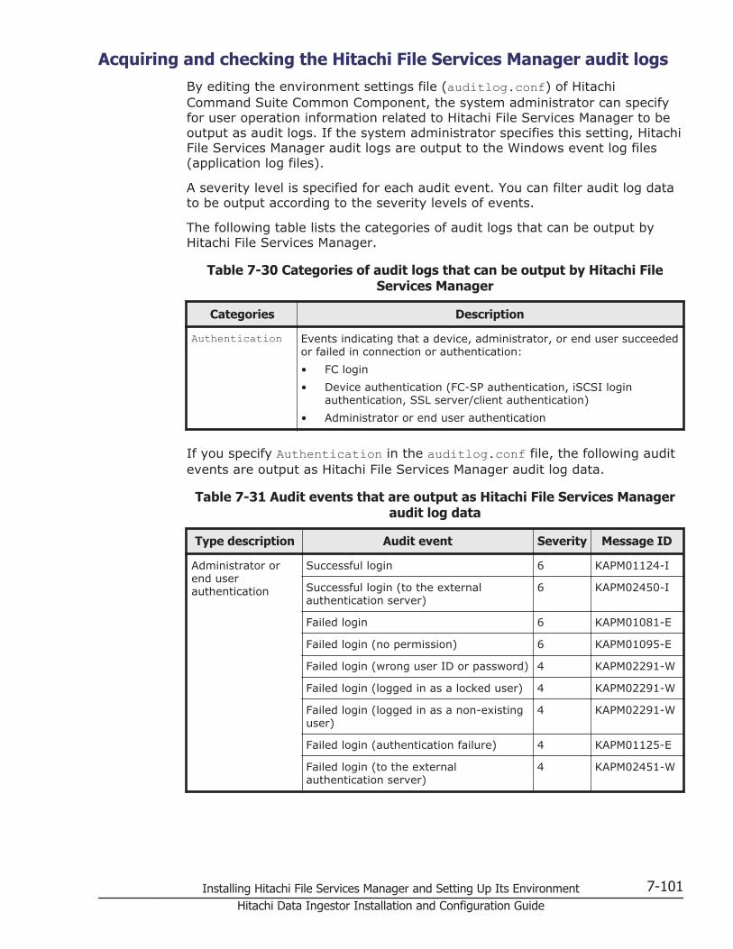
Acquiring and checking the Hitachi File Services Manager audit logsBy editing the environment settings file (auditlog.conf) of HitachiCommand Suite Common Component, the system administrator can specifyfor user operation information related to Hitachi File Services Manager to beoutput as audit logs. If the system administrator specifies this setting, HitachiFile Services Manager audit logs are output to the Windows event log files(application log files).
A severity level is specified for each audit event. You can filter audit log datato be output according to the severity levels of events.
The following table lists the categories of audit logs that can be output byHitachi File Services Manager.
Table 7-30 Categories of audit logs that can be output by Hitachi FileServices Manager
Categories Description
Authentication Events indicating that a device, administrator, or end user succeededor failed in connection or authentication:
• FC login
• Device authentication (FC-SP authentication, iSCSI loginauthentication, SSL server/client authentication)
• Administrator or end user authentication
If you specify Authentication in the auditlog.conf file, the following auditevents are output as Hitachi File Services Manager audit log data.
Table 7-31 Audit events that are output as Hitachi File Services Manageraudit log data
Type description Audit event Severity Message ID
Administrator orend userauthentication
Successful login 6 KAPM01124-I
Successful login (to the externalauthentication server)
6 KAPM02450-I
Failed login 6 KAPM01081-E
Failed login (no permission) 6 KAPM01095-E
Failed login (wrong user ID or password) 4 KAPM02291-W
Failed login (logged in as a locked user) 4 KAPM02291-W
Failed login (logged in as a non-existinguser)
4 KAPM02291-W
Failed login (authentication failure) 4 KAPM01125-E
Failed login (to the externalauthentication server)
4 KAPM02451-W
Installing Hitachi File Services Manager and Setting Up Its Environment 7-101Hitachi Data Ingestor Installation and Configuration Guide
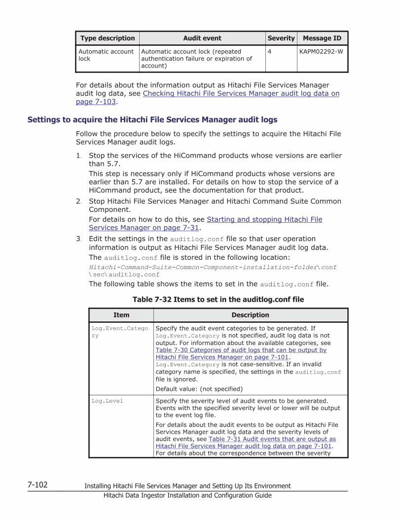
Type description Audit event Severity Message ID
Automatic accountlock
Automatic account lock (repeatedauthentication failure or expiration ofaccount)
4 KAPM02292-W
For details about the information output as Hitachi File Services Manageraudit log data, see Checking Hitachi File Services Manager audit log data onpage 7-103.
Settings to acquire the Hitachi File Services Manager audit logs
Follow the procedure below to specify the settings to acquire the Hitachi FileServices Manager audit logs.
1. Stop the services of the HiCommand products whose versions are earlierthan 5.7.This step is necessary only if HiCommand products whose versions areearlier than 5.7 are installed. For details on how to stop the service of aHiCommand product, see the documentation for that product.
2. Stop Hitachi File Services Manager and Hitachi Command Suite CommonComponent.For details on how to do this, see Starting and stopping Hitachi FileServices Manager on page 7-31.
3. Edit the settings in the auditlog.conf file so that user operationinformation is output as Hitachi File Services Manager audit log data.The auditlog.conf file is stored in the following location:Hitachi-Command-Suite-Common-Component-installation-folder\conf\sec\auditlog.confThe following table shows the items to set in the auditlog.conf file.
Table 7-32 Items to set in the auditlog.conf file
Item Description
Log.Event.Category
Specify the audit event categories to be generated. IfLog.Event.Category is not specified, audit log data is notoutput. For information about the available categories, seeTable 7-30 Categories of audit logs that can be output byHitachi File Services Manager on page 7-101.Log.Event.Category is not case-sensitive. If an invalidcategory name is specified, the settings in the auditlog.conffile is ignored.
Default value: (not specified)
Log.Level Specify the severity level of audit events to be generated.Events with the specified severity level or lower will be outputto the event log file.
For details about the audit events to be output as Hitachi FileServices Manager audit log data and the severity levels ofaudit events, see Table 7-31 Audit events that are output asHitachi File Services Manager audit log data on page 7-101.For details about the correspondence between the severity
7-102 Installing Hitachi File Services Manager and Setting Up Its EnvironmentHitachi Data Ingestor Installation and Configuration Guide

Item Description
levels of audit events and the types of event log data, seeTable 7-33 Correspondence between the severity levels ofaudit events and the types of event log data on page 7-103.
If you specify a value outside of the range of specifiable valuesor if you specify a non-numeric character, the default value isused.
• Specifiable values: 0 to 7 (severity level)
• Default value: 6
The table below shows the correspondence between the severity levels ofaudit events and the types of event log data.
Table 7-33 Correspondence between the severity levels of audit eventsand the types of event log data
Severity of audit events Type of event log data
0 Error
1
2
3
4 Warning
5 Information
6
7
The following example shows how to configure the auditlog.conf file:
Log.Event.Category AuthenticationLog.Level 6
In this example, the audit events in the Authentication audit logcategory that have a severity level in the range from 0 to 6 are output.
4. Start Hitachi File Services Manager and Hitachi Command Suite CommonComponent.For details on how to do this, see Starting and stopping Hitachi FileServices Manager on page 7-31.
5. If you stopped services in step 1, start them.This step is necessary only if HiCommand products whose versions areearlier than 5.7 are installed. For details on how to start the service of aHiCommand product, see the documentation for that product.
Checking Hitachi File Services Manager audit log data
Hitachi File Services Manager audit log data is output to the following eventlogs on the management server:
Installing Hitachi File Services Manager and Setting Up Its Environment 7-103Hitachi Data Ingestor Installation and Configuration Guide
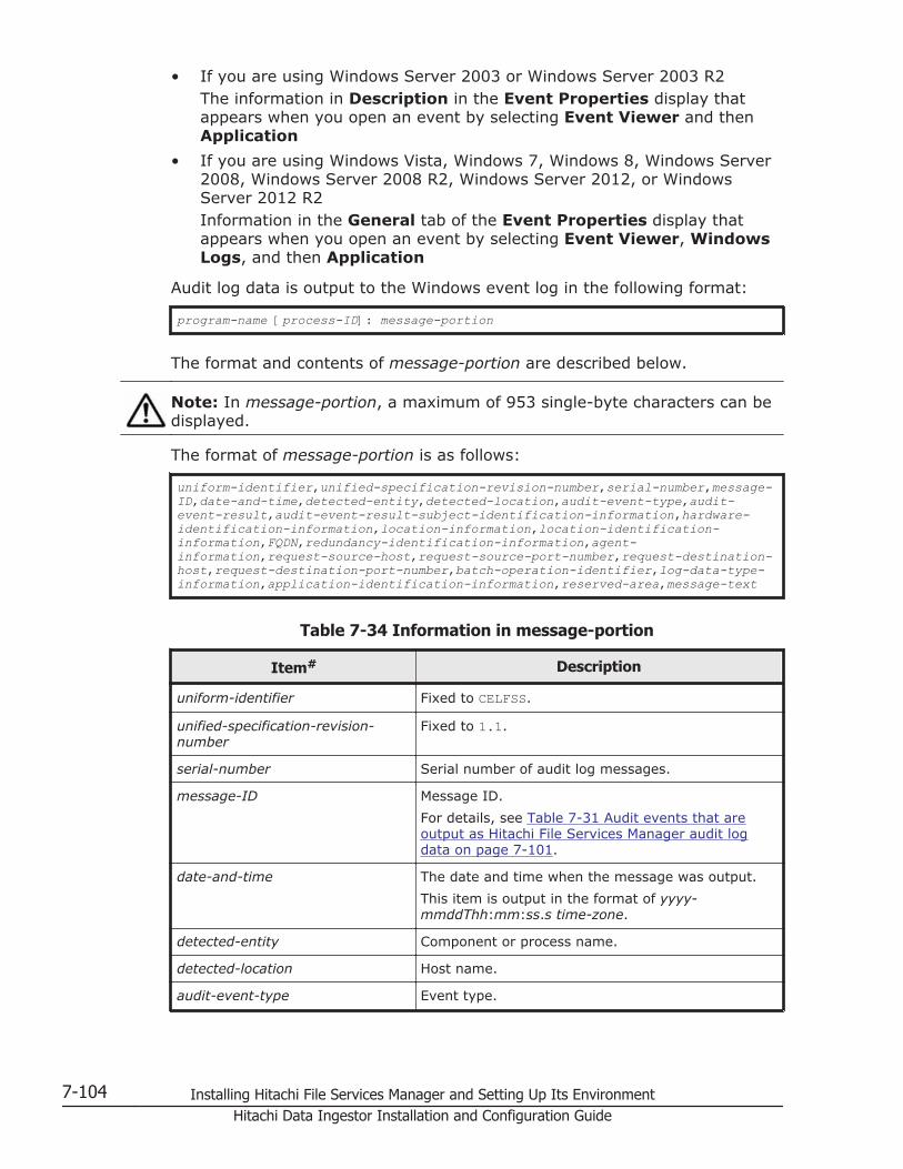
• If you are using Windows Server 2003 or Windows Server 2003 R2The information in Description in the Event Properties display thatappears when you open an event by selecting Event Viewer and thenApplication
• If you are using Windows Vista, Windows 7, Windows 8, Windows Server2008, Windows Server 2008 R2, Windows Server 2012, or WindowsServer 2012 R2Information in the General tab of the Event Properties display thatappears when you open an event by selecting Event Viewer, WindowsLogs, and then Application
Audit log data is output to the Windows event log in the following format:
program-name [process-ID]: message-portion
The format and contents of message-portion are described below.
Note: In message-portion, a maximum of 953 single-byte characters can bedisplayed.
The format of message-portion is as follows:
uniform-identifier,unified-specification-revision-number,serial-number,message-ID,date-and-time,detected-entity,detected-location,audit-event-type,audit-event-result,audit-event-result-subject-identification-information,hardware-identification-information,location-information,location-identification-information,FQDN,redundancy-identification-information,agent-information,request-source-host,request-source-port-number,request-destination-host,request-destination-port-number,batch-operation-identifier,log-data-type-information,application-identification-information,reserved-area,message-text
Table 7-34 Information in message-portion
Item# Description
uniform-identifier Fixed to CELFSS.
unified-specification-revision-number
Fixed to 1.1.
serial-number Serial number of audit log messages.
message-ID Message ID.
For details, see Table 7-31 Audit events that areoutput as Hitachi File Services Manager audit logdata on page 7-101.
date-and-time The date and time when the message was output.
This item is output in the format of yyyy-mmddThh:mm:ss.s time-zone.
detected-entity Component or process name.
detected-location Host name.
audit-event-type Event type.
7-104 Installing Hitachi File Services Manager and Setting Up Its EnvironmentHitachi Data Ingestor Installation and Configuration Guide
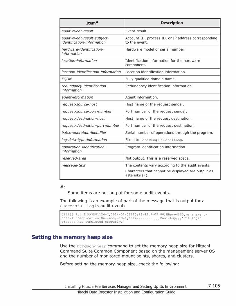
Item# Description
audit-event-result Event result.
audit-event-result-subject-identification-information
Account ID, process ID, or IP address correspondingto the event.
hardware-identification-information
Hardware model or serial number.
location-information Identification information for the hardwarecomponent.
location-identification-information Location identification information.
FQDN Fully qualified domain name.
redundancy-identification-information
Redundancy identification information.
agent-information Agent information.
request-source-host Host name of the request sender.
request-source-port-number Port number of the request sender.
request-destination-host Host name of the request destination.
request-destination-port-number Port number of the request destination.
batch-operation-identifier Serial number of operations through the program.
log-data-type-information Fixed to BasicLog or DetailLog.
application-identification-information
Program identification information.
reserved-area Not output. This is a reserved space.
message-text The contents vary according to the audit events.
Characters that cannot be displayed are output asasterisks (*).
#:Some items are not output for some audit events.
The following is an example of part of the message that is output for aSuccessful login audit event:
CELFSS,1.1,2,KAPM01124-I,2014-02-06T20:18:42.9+09:00,HBase-SSO,management-host,Authentication,Success,uid=system,,,,,,,,,,,,BasicLog,,,"The login process has completed properly."
Setting the memory heap sizeUse the hcmdschgheap command to set the memory heap size for HitachiCommand Suite Common Component based on the management server OSand the number of monitored mount points, shares, and clusters.
Before setting the memory heap size, check the following:
Installing Hitachi File Services Manager and Setting Up Its Environment 7-105Hitachi Data Ingestor Installation and Configuration Guide

• Number of mount points and shares to be monitoredCalculate the necessary memory heap size based on the number of mountpoints for file systems, as well as the number of NFS shares and CIFSshares.
Table 7-35 Memory heap size indications for Hitachi Command SuiteCommon Component
Environment Memory heap size indication#
OS Managementtargets
Medium(minimum: 256
MB,maximum: 512
MB)
Large(minimum:
512MB,maximum: 1,024
MB)
Windows (x86) Total number ofmount points
Less than 6,145 --
Total number ofshares
Less than 7,501 --
Other thanWindows (x86)
Total number ofmount points
Less than 6,145 6,145 or more
Total number ofshares
Less than 7,501 7,501 or more
Legend: -- : Cannot be set
#:Small cannot be specified.
• Number of clusters to be monitoredSet the memory heap size based on the number of clusters to bemonitored by the management server, as follows:
¢ When managing one cluster, set the memory heap size to Medium.
¢ When managing two or more clusters, set the memory heap size toLarge.
If the memory heap size calculated by the number of mount points andshares is different from the actual value, set the greater of the twovalues.
To set the memory heap size, perform the following procedure:
1. Stop Hitachi File Services Manager and Hitachi Command Suite CommonComponent.For details on how to do this, see Stopping Hitachi File Services Manageron page 7-33.
2. Execute the following command to check the current memory heap sizesetting.
Hitachi-Command-Suite-Common-Component-installation-folder\bin\hcmdschgheap /print
7-106 Installing Hitachi File Services Manager and Setting Up Its EnvironmentHitachi Data Ingestor Installation and Configuration Guide
3. Execute the following command to change the memory heap size.
Hitachi-Command-Suite-Common-Component-installation-folder\bin\hcmdschgheap /set [Small|Medium|Large]
4. Start Hitachi File Services Manager and Hitachi Command Suite CommonComponent.For details on how to do this, see Starting Hitachi File Services Manageron page 7-32.
Caution: If the hcmdsweb or hcmdsweb2 command was used to set the heapsize, the current size cannot be reduced. If you want to set a smaller size,uninstall Hitachi File Services Manager and any other Hitachi Command Suiteproducts, and then re-install them to set your desired heap size.
Maintenance of the management serverThis section describes how to execute a command of Hitachi Command SuiteCommon Component to manage the database of the management server.
Backing up or restoring the database of the management serverThis subsection describes how to back up and restore the database of HitachiFile Services Manager or a Hitachi Command Suite product.
Hitachi Data Systems recommend that you back up the databases of HitachiFile Services Manager and Hitachi Command Suite products periodically.
Note that you must back up the databases beforehand when performing thefollowing operations:
• Performing an upgrade installation or overwrite installation of Hitachi FileServices Manager
• Installing a Hitachi Command Suite product on the management server
• Uninstalling a Hitachi Command Suite product from the managementserver
• Installing Hitachi File Services Manager on the management server whereHitachi Command Suite products are already installed
• Uninstalling Hitachi File Services Manager from the management serverwhere Hitachi Command Suite products are already installed
Backing up the database
The system administrator can back up the databases of Hitachi File ServicesManager and Hitachi Command Suite products by using commands.
To back up the Hitachi File Services Manager database, a folder that willcontain the backup files is required. The folder requires the following amountof free space, which includes the space for temporary files created by thebackup command:
Installing Hitachi File Services Manager and Setting Up Its Environment 7-107Hitachi Data Ingestor Installation and Configuration Guide

Required free space:sum-of-the-database-sizes-for-the-target-Hitachi-Command-Suite-products x 2 + 5 MB
To back up the databases of Hitachi File Services Manager and HitachiCommand Suite products
1. Stop the Tuning Manager service connected to the Device Manager on themanagement server.This step is necessary if Hitachi Command Suite products including DeviceManager have been installed on the management server, and TuningManager connected to that Device Manager has been installed on anothercomputer. Stop the Tuning Manager service from the computer whereTuning Manager has been installed. For details about how to stop theTuning Manager service, see the manual for the installed version ofTuning Manager.
2. Stop the services of HiCommand products older than version 05-70.This step is necessary if HiCommand products older than version 05-70are installed on the same computer as the one on which the managementserver is installed. For details about how to stop the product services, seethe relevant product manuals.If Hitachi Command Suite products of version 05-70 or later are installedon the same computer as the one on which the management server isinstalled, first make sure that stopping Hitachi File Services Manager,Hitachi Command Suite Common Component, and the services of thoseHitachi Command Suite products will not cause problems, and thenproceed to step 5.
3. Execute a command as follows to stop Hitachi File Services Manager andHitachi Command Suite Common Component:
Hitachi-Command-Suite-Common-Component-installation-folder\bin\hcmdssrv /stop
4. Execute a command as follows to start HiRDB:
Hitachi-Command-Suite-Common-Component-installation-folder\bin\hcmdsdbsrv /start
5. Execute a command as follows to back up the databases:
Hitachi-Command-Suite-Common-Component-installation-folder\bin\hcmdsbackups /dir backup-target-folder [/auto]
Specify the /auto option if any Hitachi Command Suite products ofversion 05-70 or later are installed. The following explains the commandoptions:
/dirSpecify backup-target-folder (the folder on the local disk for storingthe backup file of the Hitachi File Services Manager database) byabsolute path. If specifying an existing folder, make sure that it isempty.
7-108 Installing Hitachi File Services Manager and Setting Up Its EnvironmentHitachi Data Ingestor Installation and Configuration Guide
You can use alphanumeric characters, spaces, exclamation marks (!),hash marks (#), left parentheses ((), right parentheses ()), plus signs(+), hyphens (-), periods (.), equal signs (=), at marks (@), leftsquare brackets ([), right square brackets (]), carets (^), underscores(_), left curly brackets ({), right curly brackets (}), and tildes (~). Asa path delimiter, you can use a forward slash (/), colon (:), orbackslash (\).
When you execute the hcmdsbackups command, a folder nameddatabase is created in the backup target folder and the databasebackup file is saved with the file name backup.hdb.
/autoAs preparation for backing up the databases, this option stops theservices of Hitachi Command Suite Common Component and HitachiCommand Suite products that are version 05-70 or later, and startsHiRDB automatically. After execution of the hcmdsbackups command,the Hitachi Command Suite Common Component and HitachiCommand Suite product services are restarted. You can specify the /auto option only when a Hitachi Command Suite product of version05-70 or later is installed.Even if you specify the /auto option, if Tuning Manager connected toDevice Manager is installed on a computer other than the one wherethe Device Manager is installed, the Tuning Manager service will notbe automatically started or stopped.
6. If you stopped Hitachi File Services Manager and Hitachi Command SuiteCommon Component in step 3, execute the following command to restartthem:
Hitachi-Command-Suite-Common-Component-installation-folder\bin\hcmdssrv /start
7. Restart any services that you stopped in step 2.This step is necessary if a Hitachi Command Suite product older thanversion 05-70 is installed. For details about how to start the productservice, see the relevant product manual.
8. If you stopped the Tuning Manager service in step 1, restart the service.This step is necessary if Hitachi Command Suite products including DeviceManager have been installed on the management server, and TuningManager connected to that Device Manager has been installed on anothercomputer. Start the Tuning Manager service on the computer whereTuning Manager has been installed.
Restoring the database
The system administrator can restore the backed up database of Hitachi FileServices Manager using commands. The databases of installed HitachiCommand Suite products can be restored at the same time as a batchoperation, but first make sure that returning to the state at which the HitachiCommand Suite products were backed up will not cause any problems.
Installing Hitachi File Services Manager and Setting Up Its Environment 7-109Hitachi Data Ingestor Installation and Configuration Guide
Note: Observe the following note.Make sure that you restore the databases of Hitachi File Services Managerand Hitachi Command Suite products together as a batch operation if you areuninstalling and then re-installing Hitachi File Services Manager and HitachiCommand Suite products on the management server.
The following must be identical on the management server where thedatabases were backed up and on the management server to which thedatabases are being restored:
• Type, version, and revision of the installed Hitachi File Services Managerand Hitachi Command Suite products
• Installation folders of Hitachi File Services Manager, Hitachi CommandSuite products, and Hitachi Command Suite Common Component
• Folders in which the databases of Hitachi File Services Manager, HitachiCommand Suite products, and Hitachi Command Suite CommonComponent were created
• IP address and the host name
Also, when you execute the hcmdsdb command to restore the Hitachi FileServices Manager database, temporary files are created in the folder in whichthe backup files exist. Make sure that you have write privilege for that folderand the following amount of free space exists.
Required free space:sum-of-the-database-sizes-for-the-target-Hitachi-Command-Suite-products + 5 MB
To restore the database of Hitachi File Services Manager
1. Stop the Tuning Manager service connected to the Device Manager on themanagement server.This step is necessary if Hitachi Command Suite products including DeviceManager have been installed on the management server, and TuningManager connected to that Device Manager has been installed on anothercomputer. Stop the Tuning Manager service from the computer whereTuning Manager has been installed. For details about how to stop theTuning Manager service, see the manual for the installed version ofTuning Manager.
2. Stop the services of HiCommand products older than version 05-70.This step is necessary if HiCommand products older than version 05-70are installed on the same computer as the one on which the managementserver is installed. For details about how to stop the product services, seethe relevant product manuals.If Hitachi Command Suite products of version 05-70 or later are installedon the same computer as the one on which the management server isinstalled, first make sure that stopping Hitachi File Services Manager,Hitachi Command Suite Common Component, and the services of thoseHitachi Command Suite products will not cause problems, and thenproceed to step 4.
7-110 Installing Hitachi File Services Manager and Setting Up Its EnvironmentHitachi Data Ingestor Installation and Configuration Guide
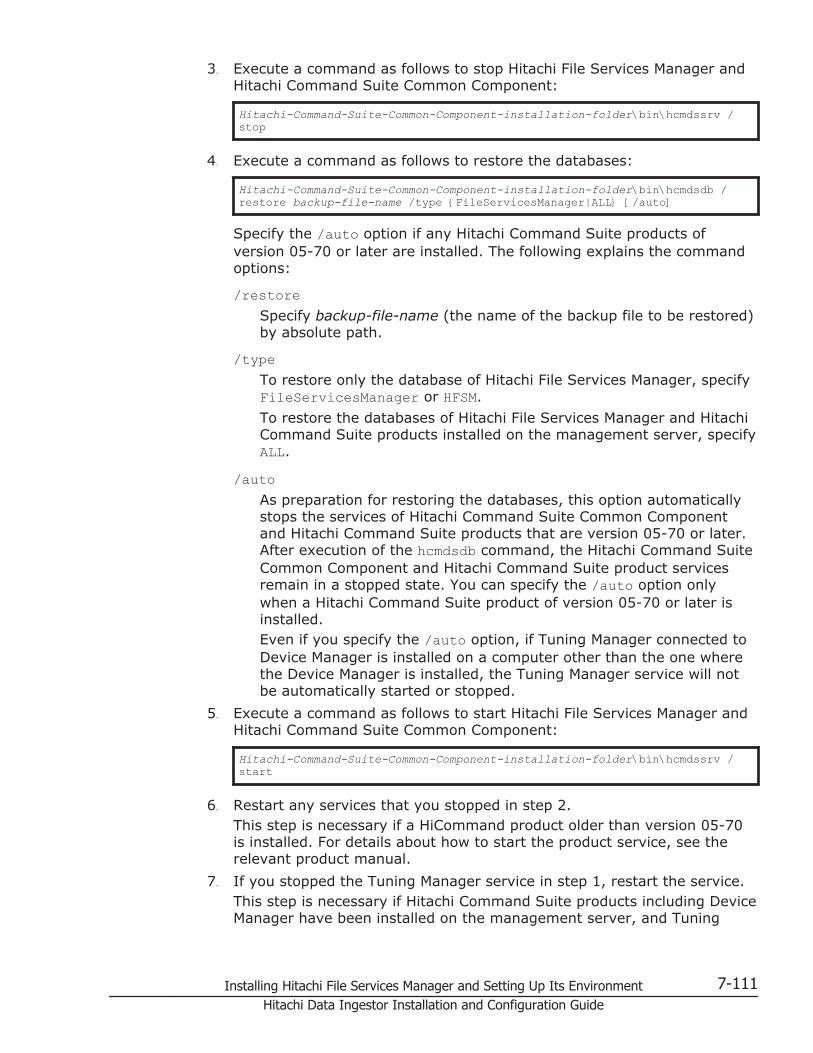
3. Execute a command as follows to stop Hitachi File Services Manager andHitachi Command Suite Common Component:
Hitachi-Command-Suite-Common-Component-installation-folder\bin\hcmdssrv /stop
4. Execute a command as follows to restore the databases:
Hitachi-Command-Suite-Common-Component-installation-folder\bin\hcmdsdb /restore backup-file-name /type {FileServicesManager|ALL} [/auto]
Specify the /auto option if any Hitachi Command Suite products ofversion 05-70 or later are installed. The following explains the commandoptions:
/restoreSpecify backup-file-name (the name of the backup file to be restored)by absolute path.
/typeTo restore only the database of Hitachi File Services Manager, specifyFileServicesManager or HFSM.
To restore the databases of Hitachi File Services Manager and HitachiCommand Suite products installed on the management server, specifyALL.
/autoAs preparation for restoring the databases, this option automaticallystops the services of Hitachi Command Suite Common Componentand Hitachi Command Suite products that are version 05-70 or later.After execution of the hcmdsdb command, the Hitachi Command SuiteCommon Component and Hitachi Command Suite product servicesremain in a stopped state. You can specify the /auto option onlywhen a Hitachi Command Suite product of version 05-70 or later isinstalled.Even if you specify the /auto option, if Tuning Manager connected toDevice Manager is installed on a computer other than the one wherethe Device Manager is installed, the Tuning Manager service will notbe automatically started or stopped.
5. Execute a command as follows to start Hitachi File Services Manager andHitachi Command Suite Common Component:
Hitachi-Command-Suite-Common-Component-installation-folder\bin\hcmdssrv /start
6. Restart any services that you stopped in step 2.This step is necessary if a HiCommand product older than version 05-70is installed. For details about how to start the product service, see therelevant product manual.
7. If you stopped the Tuning Manager service in step 1, restart the service.This step is necessary if Hitachi Command Suite products including DeviceManager have been installed on the management server, and Tuning
Installing Hitachi File Services Manager and Setting Up Its Environment 7-111Hitachi Data Ingestor Installation and Configuration Guide

Manager connected to that Device Manager has been installed on anothercomputer. Start the Tuning Manager service on the computer whereTuning Manager has been installed.
Migrating the management server from a non-cluster configurationinto a cluster configuration
This subsection describes the procedure for migrating the managementserver from a non-cluster configuration into a cluster configuration.
Each step assumes that the management server, which has already beenstarted in a non-cluster configuration, will be migrated into a clusterconfiguration under the following prerequisites:
• Set the management server, which has already been started in a non-cluster configuration, as an executing node.
• The Hitachi Command Suite products installed on the executing node arealso installed on the standby node, and licenses have been set up.
This subsection is written for Windows Server 2003. If you are using WindowsServer 2008 or Windows Server 2012, replace the term Cluster Administratorwith Failover Cluster Management as you read through the procedures. Also,refer to any related Failover Cluster Management documentation in order tonote the differences in the settings.
Migrating to cluster configurations prerequisites
Before migrating the management server into a cluster configuration, checkthe following:
• The executing node and the standby node satisfy the machinerequirements.For details about the machine requirements of the management server,see Requirements for a management server on page 3-5.
• All software programs required for the cluster configuration are installedon the executing node and the standby node.For the software programs required for the management server clusterconfiguration, see Management server cluster configuration on page 3-9.
• The shared disk is enabled on the executing node.For details about how to enable the shared disk, see Performing a newinstallation of Hitachi File Services Manager (if the management server isrunning in a cluster configuration) on page 7-16.
• For the executing node, the standby node, and the cluster managementIP address, the IP address can be resolved from the host name.
• The version of Hitachi File Services Manager to be installed on thestandby node is the same as the version on the executing node.
While performing a cluster configuration, do not access Hitachi File ServicesManager.
7-112 Installing Hitachi File Services Manager and Setting Up Its EnvironmentHitachi Data Ingestor Installation and Configuration Guide

Complete the management server settings on the executing node first, andthen perform the settings on the standby node.
Settings on the executing node of the management server
The following describes the procedure to specify the settings on the executingnode when you migrate the management server from a non-clusterconfiguration into a cluster configuration.
To specify the settings on the executing node of the managementserver
1. Back up the database.For details about how to back up the database, see Backing up orrestoring the database of the management server on page 7-107.
2. Use a text editor to create a cluster-configuration file.Specify the following items in the cluster-configuration file:
¢ modeSpecify online.
¢ virtualhostSpecify the logical host name.
¢ onlinehostSpecify the host name of the executing node.
¢ standbyhostSpecify the host name of the standby node.
You cannot specify an IP address for virtualhost, onlinehost, andstandbyhost.
The following shows a coding example in the cluster-configuration file:
mode = onlinevirtualhost = hicommand_clusteronlinehost = hicommand_1standbyhost = hicommand_2
3. Save the created cluster-configuration file using the name cluster.confin the following location:Hitachi-Command-Suite-Common-Component-installation-folder\conf\
4. Stop the Tuning Manager service connected to the Device Manager on themanagement server.This step is necessary if Hitachi Command Suite products including DeviceManager have been installed on the management server, and TuningManager connected to that Device Manager has been installed on anothercomputer. Stop the Tuning Manager service from the computer whereTuning Manager has been installed. For details about how to stop theTuning Manager service, see the manual for the installed version ofTuning Manager.
5. Stop the services of HiCommand products older than version 05-70.This step is necessary if HiCommand products older than version 05-70are installed on the same computer as the one on which the management
Installing Hitachi File Services Manager and Setting Up Its Environment 7-113Hitachi Data Ingestor Installation and Configuration Guide

server is installed. For details about how to stop the product services, seethe relevant product manuals.If Hitachi Command Suite products of version 05-70 or later are installedon the same computer as the one on which the management server isinstalled, first make sure that stopping Hitachi File Services Manager,Hitachi Command Suite Common Component, and the services of thoseHitachi Command Suite products will not cause problems, and thenproceed to step 10.
6. Execute a command as follows to stop Hitachi File Services Manager andHitachi Command Suite Common Component:
Hitachi-Command-Suite-Common-Component-installation-folder\bin\hcmdssrv /stop
7. Execute a command as follows to start HiRDB:
Hitachi-Command-Suite-Common-Component-installation-folder\bin\hcmdsdbsrv /start
8. Execute a command as follows to migrate the database to a shared disk:
Hitachi-Command-Suite-Common-Component-installation-folder\bin\hcmdsdbclustersetup /createcluster /databasepath database-re-creation-destination-folder /exportpath data-storage-destination-folder [/auto]
Specify the /auto option if any Hitachi Command Suite products ofversion 05-70 or later are installed. Specify command arguments underthe following conditions:
¢ Specify the folders by absolute path. Enter no more than 92 bytes fordatabase-re-creation-destination-folder and no more than 85 bytes fordata-storage-destination-folder.
¢ Specify a location on the shared disk for database-re-creation-destination-folder.
¢ Specify a location on the local disk for data-storage-destination-folder.
¢ If specifying an existing folder for data-storage-destination-folder,make sure that it is empty.
¢ For database-re-creation-destination-folder and data-storage-destination-folder, the following characters can be used: alphanumericcharacters, left parentheses ((), right parentheses ()), periods (.),underscores (_), and spaces. Note that the character string cannotstart or end with a period (.) or a space. In addition, you cannotspecify two or more consecutive spaces.
¢ For database-re-creation-destination-folder and data-storage-destination-folder, a backslash (\) can be used as a path delimiter.However, the character string cannot end with a backslash (\).
The space required for database-re-creation-destination-folder can becalculated as follows:required-space = 2.1 GB + database-capacity-for-other-Hitachi-Command-Suite-products
7-114 Installing Hitachi File Services Manager and Setting Up Its EnvironmentHitachi Data Ingestor Installation and Configuration Guide

If the hcmdsdbclustersetup command execution fails because there isnot enough space for database-re-creation-destination-folder, increasethe space for the folder, and then re-execute the command.Do not disconnect the shared disk from the executing node until thecommand execution ends normally.If the command execution ends abnormally and then you restart theserver, the connection target of the shared disk might be changed to thestandby node.Executing the hcmdsdbclustersetup command resets the port numberused by HiRDB to the default (23032). If you omit the /auto option,Hitachi File Services Manager and Hitachi Command Suite CommonComponent restart after the command is executed.Even if you specify the /auto option, if Tuning Manager connected toDevice Manager is installed on a computer other than the one where theDevice Manager is installed, the Tuning Manager service will not beautomatically started or stopped.
9. If HiRDB uses a port number other than the default value (23032) whenperforming operations, reset the port number to the desired value.For details about how to change the port number used by HiRDB, seeChanging the port numbers used by Hitachi Command Suite CommonComponent on page 7-89.
10. Execute a command as follows to stop Hitachi File Services Manager andHitachi Command Suite Common Component if active:
Hitachi-Command-Suite-Common-Component-installation-folder\bin\hcmdssrv /stop
11. From the Services window in Windows, open the following properties, andthen change the settings of Startup Type from Automatic to Manual:
¢ Hitachi Command Suite product services
¢ HBase Storage Mgmt Common Service
¢ HBase Storage Mgmt Web Service
¢ HiRDB/ClusterService_HD0
12. In Cluster Administrator, add the following resources to the group inwhich the resources to be used by Hitachi File Services Manager areregistered:
¢ HBase Storage Mgmt Common Service
¢ HBase Storage Mgmt Web Service
¢ HiRDB/ClusterService_HD0
¢ Hitachi Command Suite product servicesTo add HBase Storage Mgmt Common Service, HBase Storage Mgmt WebService, and HiRDB/ClusterService_HD0, select New, and thenResource, specify the information shown in Table 7-36 Settings forregistering HBase Storage Mgmt Common Service as a resource on page7-116 to Table 7-38 Settings for registering HiRDB as a resource on page7-117 in dialog boxes, and then click Finish.
Installing Hitachi File Services Manager and Setting Up Its Environment 7-115Hitachi Data Ingestor Installation and Configuration Guide
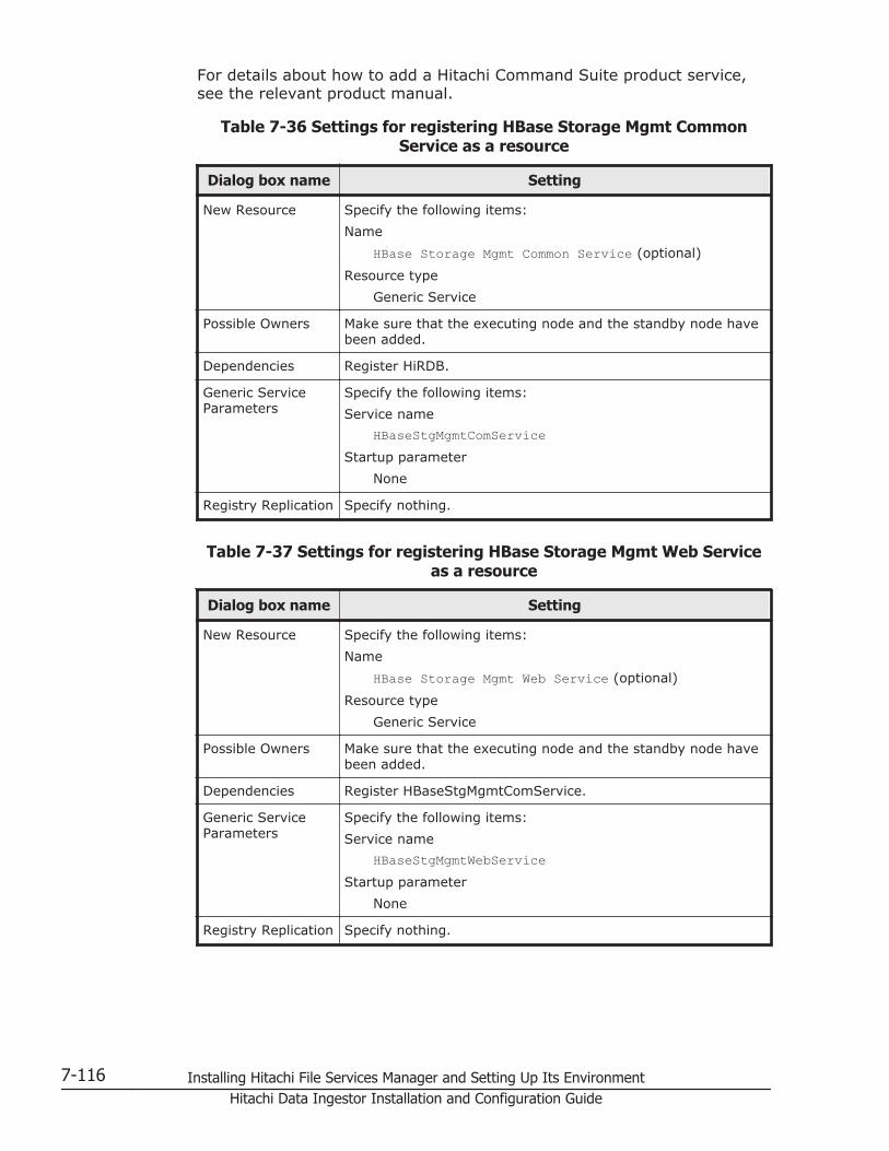
For details about how to add a Hitachi Command Suite product service,see the relevant product manual.
Table 7-36 Settings for registering HBase Storage Mgmt CommonService as a resource
Dialog box name Setting
New Resource Specify the following items:
Name
HBase Storage Mgmt Common Service (optional)
Resource type
Generic Service
Possible Owners Make sure that the executing node and the standby node havebeen added.
Dependencies Register HiRDB.
Generic ServiceParameters
Specify the following items:
Service name
HBaseStgMgmtComServiceStartup parameter
None
Registry Replication Specify nothing.
Table 7-37 Settings for registering HBase Storage Mgmt Web Serviceas a resource
Dialog box name Setting
New Resource Specify the following items:
Name
HBase Storage Mgmt Web Service (optional)
Resource type
Generic Service
Possible Owners Make sure that the executing node and the standby node havebeen added.
Dependencies Register HBaseStgMgmtComService.
Generic ServiceParameters
Specify the following items:
Service name
HBaseStgMgmtWebServiceStartup parameter
None
Registry Replication Specify nothing.
7-116 Installing Hitachi File Services Manager and Setting Up Its EnvironmentHitachi Data Ingestor Installation and Configuration Guide

Table 7-38 Settings for registering HiRDB as a resource
Dialog box name Setting
New Resource Specify the following items:
Name
HiRDB (optional)
Resource type
Generic Service
Possible Owners Make sure that the executing node and the standby node havebeen added.
Dependencies Register the drive of the shared disk and the network name.
Generic ServiceParameters
Specify the following items:
Service name
HiRDBClusterService_HD0Startup parameter
None
Registry Replication Specify nothing.
If you are using Windows Server 2008 or Windows Server 2012, executethe following command from the command prompt:
cluster res "resource-name" /priv StartupParameters=""
For resource-name, specify the resource name of the HBase StorageMgmt Web Service generic service. Confirm the resource name fromFailover Cluster Management.
Settings on the standby node of the management server
To specify the settings on the standby node when you migrate themanagement server from a non-cluster configuration into a clusterconfiguration
1. On the standby node, perform a new installation of Hitachi File ServicesManager. The version must be the same as the version of Hitachi FileServices Manager on the executing node.For details about how to install Hitachi File Services Manager for the firsttime, see Performing a new installation of Hitachi File Services Manageron page 7-2. When performing an installation, use the default values forthe folders that store the database of Hitachi Command Suite CommonComponent and the management server.
2. Stop the Tuning Manager service connected to the Device Manager on themanagement server.This step is necessary if Hitachi Command Suite products including DeviceManager have been installed on the management server, and TuningManager connected to that Device Manager has been installed on anothercomputer. Stop the Tuning Manager service from the computer where
Installing Hitachi File Services Manager and Setting Up Its Environment 7-117Hitachi Data Ingestor Installation and Configuration Guide

Tuning Manager has been installed. For details about how to stop theTuning Manager service, see the manual for the installed version ofTuning Manager.
3. Stop the services of HiCommand products older than version 05-70.This step is necessary if HiCommand products older than version 05-70are installed on the same computer as the one on which the managementserver is installed. For details about how to stop the product services, seethe relevant product manuals.If Hitachi Command Suite products of version 05-70 or later are installedon the same computer as the one on which the management server isinstalled, first make sure that stopping Hitachi File Services Manager,Hitachi Command Suite Common Component, and the services of thoseHitachi Command Suite products will not cause problems, and thenproceed to step 8.
4. Execute a command as follows to stop Hitachi File Services Manager andHitachi Command Suite Common Component:
Hitachi-Command-Suite-Common-Component-installation-folder\bin\hcmdssrv /stop
5. Execute a command as follows to start HiRDB:
Hitachi-Command-Suite-Common-Component-installation-folder\bin\hcmdsdbsrv /start
6. Use a text editor to create a cluster-configuration file.Specify the following items in the cluster-configuration file:
¢ modeSpecify standby.
¢ virtualhostSpecify the logical host name.
¢ onlinehostSpecify the host name of the executing node.
¢ standbyhostSpecify the host name of the standby node.
You cannot specify an IP address for virtualhost, onlinehost, andstandbyhost.
The following shows a coding example in the cluster-configuration file:
mode = standbyvirtualhost = hicommand_clusteronlinehost = hicommand_1standbyhost = hicommand_2
7. Save the created cluster-configuration file using the name cluster.confin the following location:Hitachi-Command-Suite-Common-Component-installation-folder\conf\
8. Execute a command as follows to specify the settings so that thedatabase on the shared disk is to be used:
7-118 Installing Hitachi File Services Manager and Setting Up Its EnvironmentHitachi Data Ingestor Installation and Configuration Guide

Hitachi-Command-Suite-Common-Component-installation-folder\bin\hcmdsdbclustersetup /createcluster /databasepath database-re-creation-destination-folder /exportpath data-storage-destination-folder [/auto]
Specify the /auto option if any Hitachi Command Suite products ofversion 05-70 or later are installed. Specify the command argumentsaccording to the following rules:
¢ For database-re-creation-destination-folder, specify the same folderas the executing node.
¢ For data-storage-destination-folder, specify the absolute path in nomore than 85 bytes.
¢ Specify a location on the local disk for data-storage-destination-folder.
¢ If specifying an existing folder for data-storage-destination-folder,make sure that it is empty.
¢ For data-storage-destination-folder, the following characters can beused: alphanumeric characters, left parentheses ((), rightparentheses ()), periods (.), underscores (_), and spaces. Note thatthe character string cannot start or end with a period (.) or a space.In addition, you cannot specify two or more consecutive spaces.
¢ For data-storage-destination-folder, a backslash (\) can be used as apath delimiter. However, the character string cannot end with abackslash (\).
Do not disconnect the shared disk from the executing node until thehcmdsdbclustersetup command execution ends normally.
If the command execution ends abnormally, do not restart the server.Executing the hcmdsdbclustersetup command resets the port numberused by HiRDB to the default (23032). If you omit the /auto option,Hitachi File Services Manager and Hitachi Command Suite CommonComponent restart after the command is executed.Even if you specify the /auto option, if Tuning Manager connected toDevice Manager is installed on a computer other than the one where theDevice Manager is installed, the Tuning Manager service will not beautomatically started or stopped.
9. If HiRDB uses a port number other than the default value (23032) whenperforming operations, reset the port number to the desired value.For details about how to change the port number used by HiRDB, seeChanging the port numbers used by Hitachi Command Suite CommonComponent on page 7-89.
10. Execute a command as follows to stop Hitachi File Services Manager andHitachi Command Suite Common Component, if active:
Hitachi-Command-Suite-Common-Component-installation-folder\bin\hcmdssrv /stop
11. From the Services window in Windows, open the following properties, andthen change the settings of Startup Type from Automatic to Manual:
¢ Hitachi Command Suite product services
Installing Hitachi File Services Manager and Setting Up Its Environment 7-119Hitachi Data Ingestor Installation and Configuration Guide
¢ HBase Storage Mgmt Common Service
¢ HBase Storage Mgmt Web Service
¢ HiRDB/ClusterService_HD0
12. In Cluster Administrator, place the group online.
Migrating the database of the management serverIf you have been using Hitachi File Services Manager and Hitachi CommandSuite products for a long time, and wish to add further managed objects orupgrade your programs, you might need to replace your hardware withmachines that deliver better performance. In this case, database migrationwill be required as one of the steps of the machine replacement procedure.
You (the system administrator) can migrate databases even when theinstallation destinations of Hitachi File Services Manager differ between themigration source and migration target, or when the version of Hitachi FileServices Manager on the migration target is newer than that on the migrationsource.
This subsection describes how to migrate the database of the managementserver.
Migrating database prerequisites
The following provides some notes on the required type and version of HitachiFile Services Manager and Hitachi Command Suite products on the migrationsource and migration target, and user information on the managementserver.
Notes on the type and version of Hitachi File Services Manager and HitachiCommand Suite products on the migration source and migration target
¢ Make sure that you install all the required Hitachi File ServicesManager and Hitachi Command Suite products on the migrationtarget.You cannot migrate the databases of Hitachi File Services Managerand Hitachi Command Suite products if they are not installed on themigration target.
¢ Make sure that the versions of Hitachi File Services Manager andHitachi Command Suite products you install on the migration targetare the same as or newer than the versions on the migration source.You cannot migrate any of the databases of Hitachi File ServicesManager or Hitachi Command Suite products if the version of any oneof these programs is older than the versions on the migration source.
¢ If you migrate the database of Replication Monitor version 4.2 orearlier, upgrade Replication Monitor on the source and destinationservers to version 5.x in advance.
¢ If you migrate the Replication Monitor database to the ReplicationManager database, first upgrade Replication Monitor on the sourceserver to Replication Manager, and then migrate the database.
7-120 Installing Hitachi File Services Manager and Setting Up Its EnvironmentHitachi Data Ingestor Installation and Configuration Guide

¢ When migrating the Tuning Manager database, you need to checkwhether the database is in a migratable state. For details, refer to thesection that describes database management in the relevant TuningManager manual.
¢ If the version of Tuning Manager is earlier than 6.0 and the totalnumber of resources managed by the Tuning Manager server exceeds70 percent of the upper control limit, the database configuration willdiffer between the migration source and migration destination serversafter migration.
Notes on user information
¢ Do not migrate databases to a management server on which userinformation for Hitachi File Services Manager and Hitachi CommandSuite products already exists.If user information exists on the migration target, the userinformation will be replaced with that of the migration source.
¢ Because user information is replaced during migration, you cannotmigrate multiple management servers (each running Hitachi FileServices Manager and one or more Hitachi Command Suite products)to a single management server.
To migrate a database
1. On the migration target server, install Hitachi File Services Manager andHitachi Command Suite products whose databases you want to migrate.For details about how to install Hitachi File Services Manager, seePerforming a new installation of Hitachi File Services Manager on page7-2. For details about how to install the Hitachi Command Suite products,see the relevant product manual.
2. Export the databases on the migration source server.For details about how to export a database on the migration sourceserver, see Exporting the database on the migration source server onpage 7-121.
3. Transfer the archive file from the migration source server to the migrationtarget server.
4. On the migration target server, import the databases.For details about how to import a database on the migration targetserver, see Importing the database on the migration target server onpage 7-123.
Exporting the database on the migration source server
To export the database of Hitachi File Services Manager, the following twofolders are required: a folder for temporarily storing the database informationand a folder for storing an archive file. For each folder, secure as much freespace as the total size of the following folders:
• The folder that stores the database of Hitachi File Services Manager
Installing Hitachi File Services Manager and Setting Up Its Environment 7-121Hitachi Data Ingestor Installation and Configuration Guide

• The folder that stores the database of Hitachi Command Suite CommonComponent, excluding the SYS folder and all the files and folders underthis folder
This is an approximate value when only the database of Hitachi File ServicesManager is installed. If any Hitachi Command Suite products are installed,take the size of their databases into consideration too.
If the entire database capacity is more than 2 GB, an attempt to create anarchive file will fail when the database is exported. When the databasecapacity is more than 2 GB, use another method to migrate without using anarchive file.
To export a database from the migration source server
1. Stop the Tuning Manager service connected to the Device Manager on themanagement server.This step is necessary if Hitachi Command Suite products including DeviceManager have been installed on the management server, and TuningManager connected to that Device Manager has been installed on anothercomputer. Stop the Tuning Manager service from the computer whereTuning Manager has been installed. For details about how to stop theTuning Manager service, see the manual for the installed version ofTuning Manager.
2. Stop the services of HiCommand products older than version 05-70.This step is necessary if HiCommand products older than version 05-70are installed on the same computer as the one on which the managementserver is installed. For details about how to stop the product services, seethe relevant product manuals.If Hitachi Command Suite products of version 05-70 or later are installedon the same computer as the one on which the management server isinstalled, first make sure that stopping Hitachi File Services Manager,Hitachi Command Suite Common Component, and the services of thoseHitachi Command Suite products will not cause problems, and thenproceed to step 5.
3. Execute a command as follows to stop Hitachi File Services Manager andHitachi Command Suite Common Component:
Hitachi-Command-Suite-Common-Component-installation-folder\bin\hcmdssrv /stop
4. Execute a command as follows to start HiRDB:
Hitachi-Command-Suite-Common-Component-installation-folder\bin\hcmdsdbsrv /start
5. Execute a command as follows to export the database:
Hitachi-Command-Suite-Common-Component-installation-folder\bin\hcmdsdbtrans /export /workpath work-folder /file archive-file [/auto]
7-122 Installing Hitachi File Services Manager and Setting Up Its EnvironmentHitachi Data Ingestor Installation and Configuration Guide

Specify the /auto option if any Hitachi Command Suite products ofversion 05-70 or later are installed. The following explains the commandoptions:
/exportYou must specify this option to export a database.
/workpathFor this option, specify the absolute path of the folder (a work folder)that temporarily stores information of the exported database. Thiswork folder must be located on the local disk and must be empty.
/fileFor this option, specify the absolute path of the archive file for thedatabase.
/autoAs preparation for exporting the databases, this option stops theservices of Hitachi Command Suite Common Component and HitachiCommand Suite products that are version 05-70 or later, and startsHiRDB automatically. After execution of the hcmdsdbtrans command,the Hitachi Command Suite Common Component and HitachiCommand Suite product services are restarted. You can specify the /auto option only when a Hitachi Command Suite product of version05-70 or later is installed.Even if you specify the /auto option, if Tuning Manager connected toDevice Manager is installed on a computer other than the one wherethe Device Manager is installed, the Tuning Manager service will notbe automatically started or stopped.
6. If an error message is output, you must take action according to themessage.
7. Transfer the archive file to the migration target server.If the archive file could not be created, transfer all the files stored in thefolder that you specified for the /workpath option. When doing this, donot change the file structure under the folder specified by the /workpathoption.
Importing the database on the migration target server
To import a database into the migration target server
1. Stop the Tuning Manager service connected to the Device Manager on themanagement server.This step is necessary if Hitachi Command Suite products including DeviceManager have been installed on the management server, and TuningManager connected to that Device Manager has been installed on anothercomputer. Stop the Tuning Manager service from the computer whereTuning Manager has been installed. For details about how to stop theTuning Manager service, see the manual for the installed version ofTuning Manager.
2. Stop the services of HiCommand products older than version 05-70.
Installing Hitachi File Services Manager and Setting Up Its Environment 7-123Hitachi Data Ingestor Installation and Configuration Guide

This step is necessary if HiCommand products older than version 05-70are installed on the same computer as the one on which the managementserver is installed. For details about how to stop the product services, seethe relevant product manuals.If Hitachi Command Suite products of version 05-70 or later are installedon the same computer as the one on which the management server isinstalled, first make sure that stopping Hitachi File Services Manager,Hitachi Command Suite Common Component, and the services of thoseHitachi Command Suite products will not cause problems, and thenproceed to step 5.
3. Execute a command as follows to stop Hitachi File Services Manager andHitachi Command Suite Common Component:
Hitachi-Command-Suite-Common-Component-installation-folder\bin\hcmdssrv /stop
4. Execute a command as follows to start HiRDB:
Hitachi-Command-Suite-Common-Component-installation-folder\bin\hcmdsdbsrv /start
5. Execute a command as follows to import the database:
Hitachi-Command-Suite-Common-Component-installation-folder\bin\hcmdsdbtrans /import /workpath work-folder [/file archive-file] /type {ALL | names-of-Hitachi-File-Services-Manager-and-Hitachi-Command-Suite-products-being-migrated} [/auto]
Specify the /auto option if any Hitachi Command Suite products ofversion 05-70 or later are installed. The following explains the commandoptions:
/importYou must specify this option to import a database.
/workpathTo import a database by using an archive file:Specify the absolute path of the folder (a work folder) that is used toextract an archive file. This work folder must be located on the localdisk and must be empty. When an archive file is used, you mustspecify the /file option.
To import a database by not using an archive file:Specify a folder that stores the information of the database that wastransferred from the migration source. Do not specify the /fileoption.
/fileSpecify the absolute path of the database archive file transferred fromthe migration source server. If the database information transferredfrom the migration source is stored in the folder specified by usingthe /workpath option, you can omit the /file option.
/type
7-124 Installing Hitachi File Services Manager and Setting Up Its EnvironmentHitachi Data Ingestor Installation and Configuration Guide
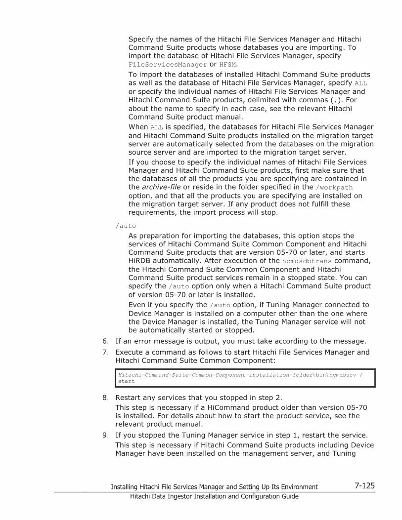
Specify the names of the Hitachi File Services Manager and HitachiCommand Suite products whose databases you are importing. Toimport the database of Hitachi File Services Manager, specifyFileServicesManager or HFSM.
To import the databases of installed Hitachi Command Suite productsas well as the database of Hitachi File Services Manager, specify ALLor specify the individual names of Hitachi File Services Manager andHitachi Command Suite products, delimited with commas (,). Forabout the name to specify in each case, see the relevant HitachiCommand Suite product manual.When ALL is specified, the databases for Hitachi File Services Managerand Hitachi Command Suite products installed on the migration targetserver are automatically selected from the databases on the migrationsource server and are imported to the migration target server.If you choose to specify the individual names of Hitachi File ServicesManager and Hitachi Command Suite products, first make sure thatthe databases of all the products you are specifying are contained inthe archive-file or reside in the folder specified in the /workpathoption, and that all the products you are specifying are installed onthe migration target server. If any product does not fulfill theserequirements, the import process will stop.
/autoAs preparation for importing the databases, this option stops theservices of Hitachi Command Suite Common Component and HitachiCommand Suite products that are version 05-70 or later, and startsHiRDB automatically. After execution of the hcmdsdbtrans command,the Hitachi Command Suite Common Component and HitachiCommand Suite product services remain in a stopped state. You canspecify the /auto option only when a Hitachi Command Suite productof version 05-70 or later is installed.Even if you specify the /auto option, if Tuning Manager connected toDevice Manager is installed on a computer other than the one wherethe Device Manager is installed, the Tuning Manager service will notbe automatically started or stopped.
6. If an error message is output, you must take according to the message.
7. Execute a command as follows to start Hitachi File Services Manager andHitachi Command Suite Common Component:
Hitachi-Command-Suite-Common-Component-installation-folder\bin\hcmdssrv /start
8. Restart any services that you stopped in step 2.This step is necessary if a HiCommand product older than version 05-70is installed. For details about how to start the product service, see therelevant product manual.
9. If you stopped the Tuning Manager service in step 1, restart the service.This step is necessary if Hitachi Command Suite products including DeviceManager have been installed on the management server, and Tuning
Installing Hitachi File Services Manager and Setting Up Its Environment 7-125Hitachi Data Ingestor Installation and Configuration Guide

Manager connected to that Device Manager has been installed on anothercomputer. Start the Tuning Manager service on the computer whereTuning Manager has been installed.
Changing the host name or IP address of the management serverYou (the system administrator) must edit some configuration files beforechanging the host name or IP address of the management server. If themanagement server is used in a cluster configuration, information in theconfiguration files must be the same for the executing node and the standbynode.
If you have changed the host name or IP address of the management serverbefore editing the configuration files, use the hostname command or theipconfig /All command to display the new host name or IP address, andthen take note. Then, specify the noted host name as is in the configurationfiles, because a host name is case-sensitive.
The procedure for changing the host name or IP address of the managementserver is shown below. In the following procedure, the host name refers toeither the host name or the IP address:
To change the host name or IP address of the management server
1. Execute the hostname command or the ipconfig /ALL command todisplay the host name that has been used before the change, and thentake note.If an error occurred due to the host name change, use the noted hostname specified before the change to return to the original state.
2. Stop the services of HiCommand products older than version 05-70.This step is necessary if a HiCommand product older than version 05-70is installed. For details about how to stop the product service, see therelevant product manual.
3. Execute a command as follows to stop Hitachi File Services Manager andHitachi Command Suite Common Component:
Hitachi-Command-Suite-Common-Component-installation-folder\bin\hcmdssrv /stop
4. If SSL has been set, use the new host name to set SSL again.For details about how to set SSL, see Setting up SSL on page 7-91.
5. Use the new host name to edit the httpsd.conf file.
If SSL has not been set, specify the new host name for the followingitems in the httpsd.conf file.
7-126 Installing Hitachi File Services Manager and Setting Up Its EnvironmentHitachi Data Ingestor Installation and Configuration Guide
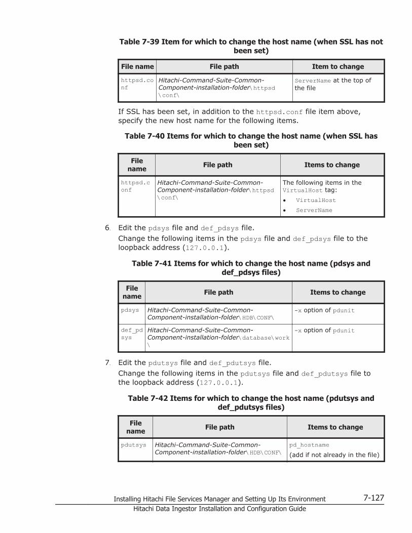
Table 7-39 Item for which to change the host name (when SSL has notbeen set)
File name File path Item to change
httpsd.conf
Hitachi-Command-Suite-Common-Component-installation-folder\httpsd\conf\
ServerName at the top ofthe file
If SSL has been set, in addition to the httpsd.conf file item above,specify the new host name for the following items.
Table 7-40 Items for which to change the host name (when SSL hasbeen set)
Filename File path Items to change
httpsd.conf
Hitachi-Command-Suite-Common-Component-installation-folder\httpsd\conf\
The following items in theVirtualHost tag:
• VirtualHost• ServerName
6. Edit the pdsys file and def_pdsys file.
Change the following items in the pdsys file and def_pdsys file to theloopback address (127.0.0.1).
Table 7-41 Items for which to change the host name (pdsys anddef_pdsys files)
Filename File path Items to change
pdsys Hitachi-Command-Suite-Common-Component-installation-folder\HDB\CONF\
-x option of pdunit
def_pdsys
Hitachi-Command-Suite-Common-Component-installation-folder\database\work\
-x option of pdunit
7. Edit the pdutsys file and def_pdutsys file.
Change the following items in the pdutsys file and def_pdutsys file tothe loopback address (127.0.0.1).
Table 7-42 Items for which to change the host name (pdutsys anddef_pdutsys files)
Filename File path Items to change
pdutsys Hitachi-Command-Suite-Common-Component-installation-folder\HDB\CONF\
pd_hostname(add if not already in the file)
Installing Hitachi File Services Manager and Setting Up Its Environment 7-127Hitachi Data Ingestor Installation and Configuration Guide

Filename File path Items to change
def_pdutsys
Hitachi-Command-Suite-Common-Component-installation-folder\database\work\
pd_hostname(add if not already in the file)
8. Edit the HiRDB.ini file.
Change the following items in the HiRDB.ini file to the loopback address(127.0.0.1).
Table 7-43 Item for which to change the host name (HiRDB.ini file)
Filename File path Item to change
HiRDB.ini
Hitachi-Command-Suite-Common-Component-installation-folder\HDB\CONF\emb\
PDHOST
9. If necessary, use the new host name to edit the cluster.conf file.
This step must be performed if the management server is running in thecluster configuration.Specify the new host name for the relevant items in the cluster.conffile, as listed in the table below.
Table 7-44 Items for which to change the host name (cluster.conf file)
File name File path Items to change
cluster.conf
Hitachi-Command-Suite-Common-Component-installation-folder\conf\
If changing the logical host name:
virtualhostIf changing the host name of theexecuting node:
onlinehostIf changing the host name of thestandby node:
standbyhost
10. Change the host name of the management server, and then restart themachine.If you have already changed the host name of the management server,just restart the machine.
11. Execute a command as follows to make sure that the service of HitachiCommand Suite Common Component is running:
Hitachi-Command-Suite-Common-Component-installation-folder\bin\hcmdssrv /status
12. Change the URL of the management server.
7-128 Installing Hitachi File Services Manager and Setting Up Its EnvironmentHitachi Data Ingestor Installation and Configuration Guide
For details about how to change the URL of the management server, seethe relevant Device Manager manual.
13. Execute a command as follows to start Hitachi File Services Manager andHitachi Command Suite Common Component:
Hitachi-Command-Suite-Common-Component-installation-folder\bin\hcmdssrv /start
14. Restart any services that you stopped in step 2.This step is necessary if a HiCommand product older than version 05-70is installed. For details about how to start the product service, see therelevant product manual.
Adjusting the management server timeThis subsection describes how to adjust the time in the management serverafter you install Hitachi File Services Manager.
To adjust the management server time after installation, use a program foradjusting the time automatically.
When using a program that adjusts the time automatically while using NTP oranother protocol, make sure that when the system clock is ahead of theactual time, the program will adjust the system clock gradually over timewithout turning the clock back. Some synchronization programs makeincremental adjustments if the time difference is within a set limit, and turnthe clock back only if the time difference is more than the limit. In thesynchronization program you are using, set the time adjustment frequency sothat the time difference will not exceed the threshold for incrementaladjustment.
For example, if you are using the Windows Time service and the system clockis ahead of the actual time by less than a set threshold, the system time canbe adjusted gradually without turning back the clock. Check the value of thisthreshold in the Windows Time service, and set the tuning frequency so thatthe difference between the system time and actual time does not exceed thethreshold.
If you do not have access to services for adjusting the system timeautomatically, or when you need to change the time immediately, set thesystem clock as follows:
To adjust the management server time
1. Stop the services of HiCommand products older than version 05-70.This step is necessary if a HiCommand product older than version 05-70is installed. For details about how to stop the product service, see therelevant product manual.
2. Execute a command as follows to stop Hitachi File Services Manager andHitachi Command Suite Common Component:
Hitachi-Command-Suite-Common-Component-installation-folder\bin\hcmdssrv /stop
Installing Hitachi File Services Manager and Setting Up Its Environment 7-129Hitachi Data Ingestor Installation and Configuration Guide

3. Record the time specified for the management server, and then changethe specified time.If you want to delay the management server time, wait until the time yourecorded has expired, and then proceed to the next step.
4. Restart the management server machine.
Disconnecting the management server networkBefore disconnecting the management server network to carry out tasks suchas replacing an NIC or maintaining the hub, the system administrator mustedit the configuration files.
The procedure for disconnecting the management server network is describedbelow. Configuration files are edited in steps 3 to 5. After you have edited thefiles in this manner, you do not need to edit them at any subsequentdisconnection of the management server network.
To disconnect the management server network
1. Stop the services of HiCommand products older than version 05-70.This step is necessary if a HiCommand product older than version 05-70is installed. For details about how to stop the product service, see therelevant product manual.
2. Execute a command as follows to stop Hitachi File Services Manager andHitachi Command Suite Common Component:
Hitachi-Command-Suite-Common-Component-installation-folder\bin\hcmdssrv /stop
3. Edit the pdsys file and def_pdsys file.
Change the following items in the pdsys file and def_pdsys file to theloopback address (127.0.0.1).
Table 7-45 Items for which to change the host name (pdsys anddef_pdsys files)
Filename File path Items to change
pdsys Hitachi-Command-Suite-Common-Component-installation-folder\HDB\CONF\
-x option of pdunit
def_pdsys
Hitachi-Command-Suite-Common-Component-installation-folder\database\work\
-x option of pdunit
4. Edit the pdutsys file and def_pdutsys file.
Change the following items in the pdutsys file and def_pdutsys file tothe loopback address (127.0.0.1).
7-130 Installing Hitachi File Services Manager and Setting Up Its EnvironmentHitachi Data Ingestor Installation and Configuration Guide
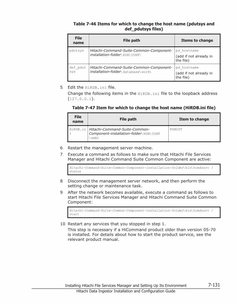
Table 7-46 Items for which to change the host name (pdutsys anddef_pdutsys files)
Filename File path Items to change
pdutsys Hitachi-Command-Suite-Common-Component-installation-folder\HDB\CONF\
pd_hostname(add if not already inthe file)
def_pdutsys
Hitachi-Command-Suite-Common-Component-installation-folder\database\work\
pd_hostname(add if not already inthe file)
5. Edit the HiRDB.ini file.
Change the following items in the HiRDB.ini file to the loopback address(127.0.0.1).
Table 7-47 Item for which to change the host name (HiRDB.ini file)
Filename File path Item to change
HiRDB.ini
Hitachi-Command-Suite-Common-Component-installation-folder\HDB\CONF\emb\
PDHOST
6. Restart the management server machine.
7. Execute a command as follows to make sure that Hitachi File ServicesManager and Hitachi Command Suite Common Component are active:
Hitachi-Command-Suite-Common-Component-installation-folder\bin\hcmdssrv /status
8. Disconnect the management server network, and then perform thesetting change or maintenance task.
9. After the network becomes available, execute a command as follows tostart Hitachi File Services Manager and Hitachi Command Suite CommonComponent:
Hitachi-Command-Suite-Common-Component-installation-folder\bin\hcmdssrv /start
10. Restart any services that you stopped in step 1.This step is necessary if a HiCommand product older than version 05-70is installed. For details about how to start the product service, see therelevant product manual.
Installing Hitachi File Services Manager and Setting Up Its Environment 7-131Hitachi Data Ingestor Installation and Configuration Guide

Changing the JDKAfter starting operation, to change the JDK used by Hitachi File ServicesManager (e.g., due to security vulnerabilities), execute the hcmdschgjdkcommand. You can change the JDK to Oracle JDK 6 or Oracle JDK 7.
The SSL certificate used by the management server to communicate withnodes is usually imported automatically when Hitachi File Services Manager isinstalled.
However, changing the JDK also changes the keystore, so you need to importthe SSL certificate manually.
Note:
• After starting operation, if you overwrote the JDK used by Hitachi FileServices Manager with Oracle JDK or performed an upgrade installation,re-register the JDK by using the hcmdschgjdk command.
• After starting operation, if you changed the JDK used by Hitachi FileServices Manager to Oracle JDK, and then had to uninstall Oracle JDK,change the JDK back to the one that came bundled with the product.
• If Hitachi Command Suite products version 7.0 or earlier are installed onthe management server, you cannot change the JDK to Oracle JDK.
To change the JDK, perform the following procedure
1. Stop the services of Hitachi File Services Manager and Hitachi CommandSuite products.For details on how to stop the services, see Stopping Hitachi File ServicesManager on page 7-33.
2. To change the JDK, execute commands as follows:
Hitachi-Command-Suite-Common-Component-installation-folder\bin\hcmdschgjdk
In the window that appears, select the JDK that you want to use.
3. Start the services of Hitachi File Services Manager and Hitachi CommandSuite products.For details about how to start the services, see Starting Hitachi FileServices Manager on page 7-32.
4. Import the SSL certificate to the keystore file of the management server(jssecacerts).
When you import the SSL certificate, the certificate is moved inside theJDK to be used.For details on how to import the SSL certificate to the managementserver, see Importing the required SSL certificate for communicationbetween the node and management server on page 7-98.
5. In environments where Windows firewall is enabled, if you change theJDK to Oracle JDK, the java.exe file of Oracle JDK needs to be manuallyregistered as an exception.
7-132 Installing Hitachi File Services Manager and Setting Up Its EnvironmentHitachi Data Ingestor Installation and Configuration Guide
AACLs Created After the File System IsMigrated to That of the Advanced ACL
Type
This appendix describes the ACLs that are created when a file system of theClassic ACL type is migrated to a file system of the Advanced ACL type.
□ ACLs Created After the File System Is Migrated to That of the AdvancedACL Type
ACLs Created After the File System Is Migrated to That of the Advanced ACL Type A-1Hitachi Data Ingestor Installation and Configuration Guide
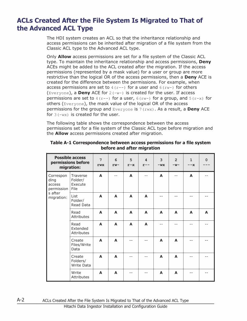
ACLs Created After the File System Is Migrated to That ofthe Advanced ACL Type
The HDI system creates an ACL so that the inheritance relationship andaccess permissions can be inherited after migration of a file system from theClassic ACL type to the Advanced ACL type.
Only Allow access permissions are set for a file system of the Classic ACLtype. To maintain the inheritance relationship and access permissions, DenyACEs might be added to the ACL created after the migration. If the accesspermissions (represented by a mask value) for a user or group are morerestrictive than the logical OR of the access permissions, then a Deny ACE iscreated for the difference between the permissions. For example, whenaccess permissions are set to 4(r--) for a user and 6(rw-) for others(Everyone), a Deny ACE for 2(-w-) is created for the user. If accesspermissions are set to 4(r--) for a user, 6(rw-) for a group, and 5(r-x) forothers (Everyone), the mask value of the logical OR of the accesspermissions for the group and Everyone is 7(rwx). As a result, a Deny ACEfor 3(-wx) is created for the user.
The following table shows the correspondence between the accesspermissions set for a file system of the Classic ACL type before migration andthe Allow access permissions created after migration.
Table A-1 Correspondence between access permissions for a file systembefore and after migration
Possible accesspermissions before
migration:
7rwx
6rw-
5r-x
4r--
3-wx
2-w-
1--x
0---
Correspondingaccesspermissions aftermigration:
TraverseFolder/ExecuteFile
A -- A -- A -- A --
ListFolder/Read Data
A A A A -- -- -- --
ReadAttributes
A A A A A A A A
ReadExtendedAttributes
A A A A -- -- -- --
CreateFiles/WriteData
A A -- -- A A -- --
CreateFolders/Write Data
A A -- -- A A -- --
WriteAttributes
A A -- -- A A -- --
A-2 ACLs Created After the File System Is Migrated to That of the Advanced ACL TypeHitachi Data Ingestor Installation and Configuration Guide

Possible accesspermissions before
migration:
7rwx
6rw-
5r-x
4r--
3-wx
2-w-
1--x
0---
WriteExtendedAttributes
A A -- -- A A -- --
DeleteSubfoldersand Files
A A -- -- A A -- --
Delete -- -- -- -- -- -- -- --
ReadPermissions
A A A A A A A A
ChangePermissions
O O O O O O O O
TakeOwnership
O O O O O O O O
Legend: A = After the migration, Allow is set. -- = After the migration,Allow is not set. O = Allow is set for access permissions of the file owner
If the access permissions for a user or group are more restrictive than thelogical OR of the access permissions before migration then, for the differencebetween the permissions, a Deny ACE is created after migration.
The mask values are calculated by the following formula:
Mask value = r x 4 + w x 2 + x x 1
Where:r: Read permission bit (0 or 1)w: Write permission bit (0 or 1)x: Execution permission bit or direct research permission bit (0 or 1)
The access is allowed if the corresponding bit is 1.
For example, if the logical OR of access permissions is 7(rwx) in the filesystem before migration, all the permission bits (r, w, x) will be 1 and themask value will be as follows:
Mask value = r x 4 + w x 2 + x x 1
= 1 x 4 + 1 x 2 + 1 x 1
= 7
The following table shows how the Deny access permission created aftermigration corresponds to the differences between the following beforemigration:
• The more restrictive access permissions for a user or group
ACLs Created After the File System Is Migrated to That of the Advanced ACL Type A-3Hitachi Data Ingestor Installation and Configuration Guide
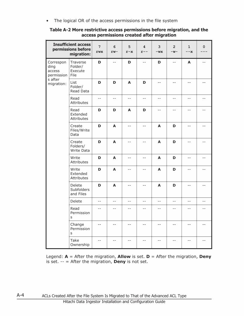
• The logical OR of the access permissions in the file system
Table A-2 More restrictive access permissions before migration, and theaccess permissions created after migration
Insufficient accesspermissions before
migration:
7rwx
6rw-
5r-x
4r--
3-wx
2-w-
1--x
0---
Correspondingaccesspermissions aftermigration:
TraverseFolder/ExecuteFile
D -- D -- D -- A --
ListFolder/Read Data
D D A D -- -- -- --
ReadAttributes
-- -- -- -- -- -- -- --
ReadExtendedAttributes
D D A D -- -- -- --
CreateFiles/WriteData
D A -- -- A D -- --
CreateFolders/Write Data
D A -- -- A D -- --
WriteAttributes
D A -- -- A D -- --
WriteExtendedAttributes
D A -- -- A D -- --
DeleteSubfoldersand Files
D A -- -- A D -- --
Delete -- -- -- -- -- -- -- --
ReadPermissions
-- -- -- -- -- -- -- --
ChangePermissions
-- -- -- -- -- -- -- --
TakeOwnership
-- -- -- -- -- -- -- --
Legend: A = After the migration, Allow is set. D = After the migration, Denyis set. -- = After the migration, Deny is not set.
A-4 ACLs Created After the File System Is Migrated to That of the Advanced ACL TypeHitachi Data Ingestor Installation and Configuration Guide

BUsing the Node Power Lamp Switch or
Power Button to Start or Stop the OS
This appendix explains how the node power lamp switch or power button isused to start or stop the OS. Normally, the GUI or CLI are used to start orstop the OS, but if you need to use a node's power lamp switch or powerbutton, follow the instructions of maintenance personnel.
First, check the product name of the node being used. You can acquire thename by using the hwstatus command. If Compute Rack is used for thenode, use the power lamp switch. If PowerEdge is used for the node, use thepower button.
□ Starting an OS
□ Forcibly Stopping an OS
Using the Node Power Lamp Switch or Power Button to Start or Stop the OS B-1Hitachi Data Ingestor Installation and Configuration Guide

Starting an OSYou can start an OS by using the power lamp switch or power button to turnon the node. To start both OSs after a planned shutdown of the OSs on bothnodes in a cluster is performed, turn on one of the nodes, and then turn theother node on within 10 minutes of turning on the first node. If this is notdone, a failover will occur on the node for which the OS has not yet beenstarted.
To start the OS by turning on the power to a node:
1. Make sure that the external servers connected to the node are running.
2. Make sure that the power lamp or power indicator (the LED on the powerlamp switch or power button) located on the front of the node is not on.
3. Make sure that the storage systems and FC switches are running.If the OS is started while the storage systems and FC switches are notrunning, FC path errors will occur.
4. Make sure that the IP switches for the management LAN are running.Note that the management server and the management console can beconnected to from the node only when the IP switches for themanagement LAN are running.
5. If you are using encryption, when you save system settings on the HCPsystem, confirm that the HCP system is running normally, and that theHDI and HCP systems can communicate normally.User data cannot be available unless the HCP system can becommunicated with.
6. Press the power lamp switch or power button located on the front of thenode.
7. Make sure that the power lamp or power indicator lights up.
Forcibly Stopping an OSIf the power lamp or power indicator cannot be turned off via the GUI orcommands, you can use the power lamp switch or power button to forciblystop an OS.
To forcibly stop the OS by turning off the power to a node:
1. Hold down the power lamp switch or power button located on the front ofthe node for 5 seconds or more.
2. Make sure that the power lamp or power indicator (the LED on the powerlamp switch or power button) is off.
B-2 Using the Node Power Lamp Switch or Power Button to Start or Stop the OSHitachi Data Ingestor Installation and Configuration Guide

CLayout of Node Ports
This appendix shows the layout of ports on nodes to be used for HDI of thecluster configuration.
□ Port layout
Layout of Node Ports C-1Hitachi Data Ingestor Installation and Configuration Guide
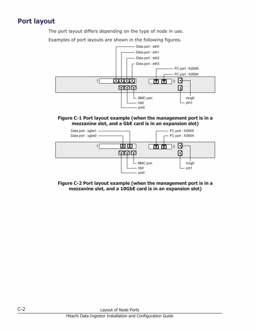
Port layoutThe port layout differs depending on the type of node in use.
Examples of port layouts are shown in the following figures.
Figure C-1 Port layout example (when the management port is in amezzanine slot, and a GbE card is in an expansion slot)
Figure C-2 Port layout example (when the management port is in amezzanine slot, and a 10GbE card is in an expansion slot)
C-2 Layout of Node PortsHitachi Data Ingestor Installation and Configuration Guide

Figure C-3 Port layout example (when the management port is inexpansion slot 1)
Figure C-4 Port layout example (when the management port is on theboard)
Layout of Node Ports C-3Hitachi Data Ingestor Installation and Configuration Guide

C-4 Layout of Node PortsHitachi Data Ingestor Installation and Configuration Guide

DStatus of IPv6 Support in External
Servers and Services
HDI systems support IPv4 and IPv6. This appendix describes the status ofIPv6 support for the external servers and services of HDI systems.
□ List of external servers and services available on IPv6
Status of IPv6 Support in External Servers and Services D-1Hitachi Data Ingestor Installation and Configuration Guide
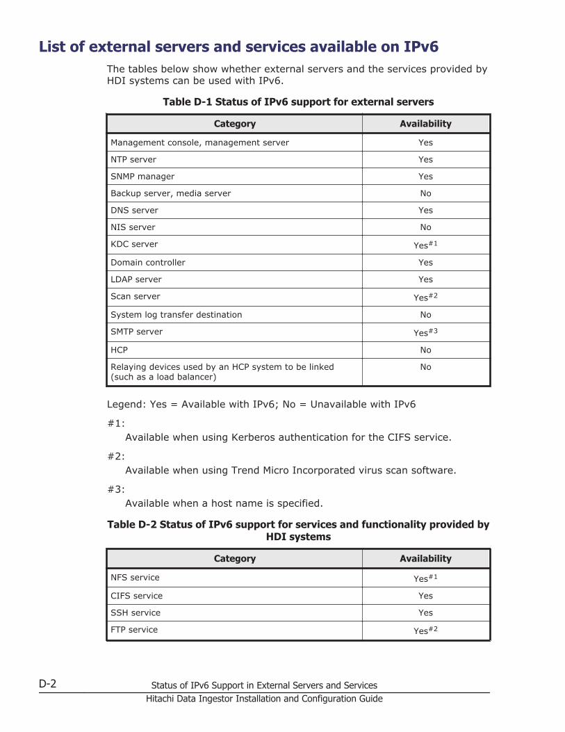
List of external servers and services available on IPv6The tables below show whether external servers and the services provided byHDI systems can be used with IPv6.
Table D-1 Status of IPv6 support for external servers
Category Availability
Management console, management server Yes
NTP server Yes
SNMP manager Yes
Backup server, media server No
DNS server Yes
NIS server No
KDC server Yes#1
Domain controller Yes
LDAP server Yes
Scan server Yes#2
System log transfer destination No
SMTP server Yes#3
HCP No
Relaying devices used by an HCP system to be linked(such as a load balancer)
No
Legend: Yes = Available with IPv6; No = Unavailable with IPv6
#1:Available when using Kerberos authentication for the CIFS service.
#2:Available when using Trend Micro Incorporated virus scan software.
#3:Available when a host name is specified.
Table D-2 Status of IPv6 support for services and functionality provided byHDI systems
Category Availability
NFS service Yes#1
CIFS service Yes
SSH service Yes
FTP service Yes#2
D-2 Status of IPv6 Support in External Servers and ServicesHitachi Data Ingestor Installation and Configuration Guide
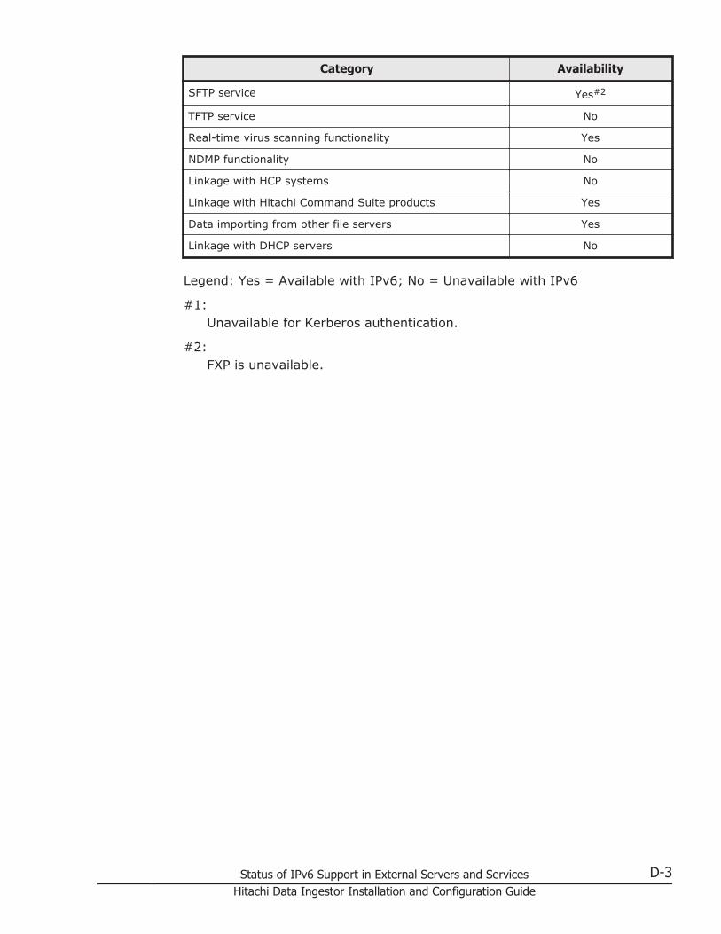
Category Availability
SFTP service Yes#2
TFTP service No
Real-time virus scanning functionality Yes
NDMP functionality No
Linkage with HCP systems No
Linkage with Hitachi Command Suite products Yes
Data importing from other file servers Yes
Linkage with DHCP servers No
Legend: Yes = Available with IPv6; No = Unavailable with IPv6
#1:Unavailable for Kerberos authentication.
#2:FXP is unavailable.
Status of IPv6 Support in External Servers and Services D-3Hitachi Data Ingestor Installation and Configuration Guide

D-4 Status of IPv6 Support in External Servers and ServicesHitachi Data Ingestor Installation and Configuration Guide

EAttributes of Directories and Files to Be
Backed Up or Restored
This appendix describes the file system information (quota information) andattributes of directories and files that are backed up to media or restoredfrom media by the NDMP functionality.
□ Attributes to be backed up
□ Attributes to be restored
Attributes of Directories and Files to Be Backed Up or Restored E-1Hitachi Data Ingestor Installation and Configuration Guide

Attributes to be backed upThe quota information and directory and file attributes that are backed up tomedia are shown in Table E-1 Quota information backed up to media on pageE-2 and Table E-2 Directory and file attributes backed up to media on pageE-2.
Table E-1 Quota information backed up to media
Type Attribute Details
Quotas set for afile system
• Default quota
• User quota
• Group quota
• Soft limit for block usage
• Hard limit for block usage
• Soft limit for inode usage
• Hard limit for inode usage
Grace period • Grace period for block usage
• Grace period for inode usage
Quotas set for adirectory (subtreequota)
• Quota for the directory
• Default quota
• User quota
• Group quota
• Soft limit for block usage
• Hard limit for block usage
• Soft limit for inode usage
• Hard limit for inode usage
Grace period • Grace period for block usage
• Grace period for inode usage
Table E-2 Directory and file attributes backed up to media
Attribute Details
inode • Path name of file
• File mode
• User ID of owner
• Group ID of owner
• Last modified time (ctime)
• Last edited time (mtime)
• Last access time (atime)
• File creation time
• Data size
• File type
• Link path name
ACL information Classic ACL Access ACL
• Access permission
• Inherited attributes
Default ACL
• Access permission
• Inherited attributes
Advanced ACL • User or group
E-2 Attributes of Directories and Files to Be Backed Up or RestoredHitachi Data Ingestor Installation and Configuration Guide

Attribute Details
• Account type
• Application destination
• Inheritance range
• ACE type
• Access permissions
File attributes Classic ACL Read
Advanced ACL • Read
• Archive
• Hidden file
• System file
WORM WORM settings information
Migration • Status of HCP system migrations
• Reference to the data on the migration-destination HCP system
Attributes to be restoredWhen backup data is restored from media, the data at the time of backup isrestored to the file system. To return the data, which you restore, to thebacked-up state, the data must be restored to the file system that has thesame settings as the backed-up settings.
If the ACL type of the backup data differs from the ACL type of the filesystem at the restore destination, the ACL information is set as shown in thefollowing table after the restore operation is performed.
Table E-3 Restoration results when ACL types differ (backup data for non-WORM file systems)
Backup dataRestoration destination file system#
Advanced ACL type Classic ACL type
Advanced ACLtype
The Advanced ACL information setfor the backup data is restored.
No ACL information is restored.
Classic ACL type The Classic ACL information set forthe backup data is converted toAdvanced ACL information duringa restore operation.
The Classic ACL information setfor the backup data is restored.
#:Both a normal file system and a WORM file system can be specified.
Attributes of Directories and Files to Be Backed Up or Restored E-3Hitachi Data Ingestor Installation and Configuration Guide

Table E-4 Restoration results when ACL types differ (backup data forWORM file systems)
Backup dataRestoration destination file system#
Advanced ACL type Classic ACL type
Advanced ACLtype
The Advanced ACL information setfor the backup data is restored.
Restoration cannot be performed.
Classic ACL type Restoration cannot be performed. The Classic ACL information setfor the backup data is restored.
#:Only WORM file systems can be specified as restoration destinations.
When the restore operation finishes, check the restored data, and thenchange the ACL settings if necessary.
E-4 Attributes of Directories and Files to Be Backed Up or RestoredHitachi Data Ingestor Installation and Configuration Guide

FAcronyms
This appendix lists the acronyms used in the HDI manuals.
□ Acronyms used in the HDI manuals
Acronyms F-1Hitachi Data Ingestor Installation and Configuration Guide

Acronyms used in the HDI manualsThe following acronyms are used in the HDI manuals.
ABE Access Based Enumeration
ACE access control entry
ACL access control list
AES Advanced Encryption Standard
AJP Apache JServ Protocol
API application programming interface
ARP Address Resolution Protocol
ASCII American Standard Code for Information Interchange
ASN Abstract Syntax Notation
BDC Backup Domain Controller
BMC baseboard management controller
CA certificate authority
CHA channel adapter
CHAP Challenge-Handshake Authentication Protocol
CIFS Common Internet File System
CIM Common Information Model
CLI command line interface
CPU central processing unit
CSR certificate signing request
CSV comma-separated values
CTL controller
CU control unit
CV custom volume
DACL discretionary access control list
DAR Direct Access Recovery
DB database
DBMS database management system
DC domain controller
DDNS Dynamic Domain Name System
DEP data execution prevention
DES Data Encryption Standard
DFS distributed file system
DHCP Dynamic Host Configuration Protocol
F-2 AcronymsHitachi Data Ingestor Installation and Configuration Guide

DIMM dual in-line memory module
DLL dynamic-link library
DN distinguished name
DNS Domain Name System
DOM Document Object Model
DOS Disk Operating System
DRAM dynamic random access memory
DSA digital signal algorithm
DTD Document Type Definition
ECC error-correcting code
EUC Extended UNIX Code
FC Fibre Channel
FC-SP Fibre Channel - Security Protocol
FIB forwarding information base
FIFO First In, First Out
FQDN fully qualified domain name
FTP File Transfer Protocol
FV Fixed Volume
FXP File Exchange Protocol
GbE Gigabit Ethernet
GID group identifier
GMT Greenwich Mean Time
GPL GNU General Public License
GUI graphical user interface
HBA host bus adapter
H-LUN host logical unit number
HPFS High Performance File System
HSSO HiCommand single sign-on
HTML HyperText Markup Language
HTTP Hypertext Transfer Protocol
HTTPS Hypertext Transfer Protocol Secure
I/O input/output
ICAP Internet Content Adaptation Protocol
ICMP Internet Control Message Protocol
ID identifier
Acronyms F-3Hitachi Data Ingestor Installation and Configuration Guide

IP Internet Protocol
IP-SW IP switch
JDK Java Development Kit
JIS Japanese Industrial Standards
JSP JavaServer Pages
KDC Key Distribution Center
LACP Link Aggregation Control Protocol
LAN local area network
LBA logical block addressing
LCD Local Configuration Datastore
LDAP Lightweight Directory Access Protocol
LDEV logical device
LDIF LDAP Data Interchange Format
LDKC logical disk controller
LED light-emitting diode
LF Line Feed
LTS long term support
LU logical unit
LUN logical unit number
LUSE logical unit size expansion
LVI Logical Volume Image
LVM Logical Volume Manager
MAC Media Access Control
MD5 Message-Digest algorithm 5
MIB management information base
MMC Microsoft Management Console
MP microprocessor
MSS maximum segment size
MTU maximum transmission unit
NAS Network-Attached Storage
NAT network address translation
NDMP Network Data Management Protocol
NetBIOS Network Basic Input/Output System
NFS Network File System
NIC network interface card
F-4 AcronymsHitachi Data Ingestor Installation and Configuration Guide
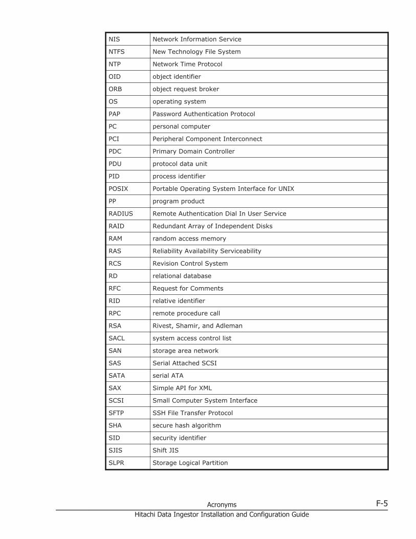
NIS Network Information Service
NTFS New Technology File System
NTP Network Time Protocol
OID object identifier
ORB object request broker
OS operating system
PAP Password Authentication Protocol
PC personal computer
PCI Peripheral Component Interconnect
PDC Primary Domain Controller
PDU protocol data unit
PID process identifier
POSIX Portable Operating System Interface for UNIX
PP program product
RADIUS Remote Authentication Dial In User Service
RAID Redundant Array of Independent Disks
RAM random access memory
RAS Reliability Availability Serviceability
RCS Revision Control System
RD relational database
RFC Request for Comments
RID relative identifier
RPC remote procedure call
RSA Rivest, Shamir, and Adleman
SACL system access control list
SAN storage area network
SAS Serial Attached SCSI
SATA serial ATA
SAX Simple API for XML
SCSI Small Computer System Interface
SFTP SSH File Transfer Protocol
SHA secure hash algorithm
SID security identifier
SJIS Shift JIS
SLPR Storage Logical Partition
Acronyms F-5Hitachi Data Ingestor Installation and Configuration Guide

SMB Server Message Block
SMD5 Salted Message Digest 5
SMTP Simple Mail Transfer Protocol
SNMP Simple Network Management Protocol
SP service pack
SSD solid-state drive
SSH Secure Shell
SSHA Salted Secure Hash Algorithm
SSL Secure Sockets Layer
SSO single sign-on
SVGA Super Video Graphics Array
TCP Transmission Control Protocol
TFTP Trivial File Transfer Protocol
TLS Transport Layer Security
TOS type of service
TTL time to live
UAC User Account Control
UDP User Datagram Protocol
UID user identifier
UNC Universal Naming Convention
UPnP Universal Plug and Play
URI Uniform Resource Identifier
URL Uniform Resource Locator
UTC Coordinated Universal Time
UTF UCS Transformation Format
VDEV Virtual Device
VLAN virtual LAN
VLL Virtual LVI/LUN
WADL Web Application Description Language
WAN wide area network
WINS Windows Internet Name Service
WORM Write Once, Read Many
WS workstation
WWN World Wide Name
WWW World Wide Web
F-6 AcronymsHitachi Data Ingestor Installation and Configuration Guide

XDR External Data Representation
XFS extended file system
XML Extensible Markup Language
Acronyms F-7Hitachi Data Ingestor Installation and Configuration Guide

F-8 AcronymsHitachi Data Ingestor Installation and Configuration Guide

Glossary
This glossary explains the terms used in the HDI manuals.
A
ACEAn entry in an ACL. An ACE sets access permissions for directories and files for eachuser and group. ACE formats differ depending on the ACL type.
ACLA list of all the ACEs for a particular directory or file. An ACL defines the accesspermissions for a particular directory or file.
ACL typeThe type of file system or file that is supported by the ACL. The ACL types that can beused in HDI systems are the Advanced ACL type (compatible with NTFS ACL), and theClassic ACL type (compatible with POSIX ACL).
Anti-Virus EnablerA program used to scan, in real time, for viruses in data shared with users via CIFS inan HDI system.
B
Backup RestoreA program used for backing up data in an HDI file system.
backup serverA server that manages backup and restore operations by using backup managementsoftware.
# A B C D E F G H I J K L M N O P Q R S T U V W X Y Z
Glossary-1Hitachi Data Ingestor Installation and Configuration Guide

C
CIFSA protocol that provides file-sharing services to Windows users.
clusterA redundant configuration that enables a service to continue when an error occurs ormaintenance work is performed.
cluster management LUAn LU that is assigned to a node and stores settings information, such as clusterconfiguration information and file system information.
command deviceA control device used to receive commands that control storage systems.
Configuration ManagerA program used to set up an HDI system and manage file system operations.
D
Data ControlOne of the programs on a node OS.
data portA node port that is used to connect to the front-end LAN.
device fileA user LU. For more information, see user LU.
Device ManagerA program that manages disk resources and the hardware configuration of storagesystems in an integrated manner.
Dynamic ProvisioningA function that virtually allocates volumes of a given capacity to a host independent ofthe physical capacity of the storage system.
Dynamic TieringThis storage system functionality automatically reallocates data based on I/O load.
# A B C D E F G H I J K L M N O P Q R S T U V W X Y Z
Glossary-2Hitachi Data Ingestor Installation and Configuration Guide

E
External storage systemA storage system that is connected to by the external storage connection functionalityfor storage systems (Universal Volume Manager).
F
failbackThe relocation of a failed-over resource group back to its original node in the clusterafter an error has been recovered on the node or maintenance on the node is complete.
failoverThe relocation of a resource group to the other node in a cluster when an error occurson a node or when maintenance on a node is required. Failovers enable continuousoperation of the services provided by an HDI system.
File SharingOne of the programs on a node OS.
fixed IP addressAn IP address set for a specific interface in a node.
front-end LANA LAN used by a client to access the data stored in a storage system.
H
HBase Storage Mgmt Common ServiceThe Web-container service for Hitachi Command Suite Common Component.
HBase Storage Mgmt Web ServiceThe Web-server service for Hitachi Command Suite Common Component.
heartbeat LANA LAN used by each node in a cluster to check the operating status of the other node.
Hitachi Command Suite Common ComponentA component that provides functions, such as being able to log in to the GUI, outputtingmanagement server integrated logs, and Web services, common to all Hitachi FileServices Manager and Hitachi Command Suite products.
# A B C D E F G H I J K L M N O P Q R S T U V W X Y Z
Glossary-3Hitachi Data Ingestor Installation and Configuration Guide
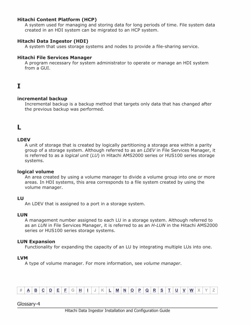
Hitachi Content Platform (HCP)A system used for managing and storing data for long periods of time. File system datacreated in an HDI system can be migrated to an HCP system.
Hitachi Data Ingestor (HDI)A system that uses storage systems and nodes to provide a file-sharing service.
Hitachi File Services ManagerA program necessary for system administrator to operate or manage an HDI systemfrom a GUI.
I
incremental backupIncremental backup is a backup method that targets only data that has changed afterthe previous backup was performed.
L
LDEVA unit of storage that is created by logically partitioning a storage area within a paritygroup of a storage system. Although referred to as an LDEV in File Services Manager, itis referred to as a logical unit (LU) in Hitachi AMS2000 series or HUS100 series storagesystems.
logical volumeAn area created by using a volume manager to divide a volume group into one or moreareas. In HDI systems, this area corresponds to a file system created by using thevolume manager.
LUAn LDEV that is assigned to a port in a storage system.
LUNA management number assigned to each LU in a storage system. Although referred toas an LUN in File Services Manager, it is referred to as an H-LUN in the Hitachi AMS2000series or HUS100 series storage systems.
LUN ExpansionFunctionality for expanding the capacity of an LU by integrating multiple LUs into one.
LVMA type of volume manager. For more information, see volume manager.
# A B C D E F G H I J K L M N O P Q R S T U V W X Y Z
Glossary-4Hitachi Data Ingestor Installation and Configuration Guide
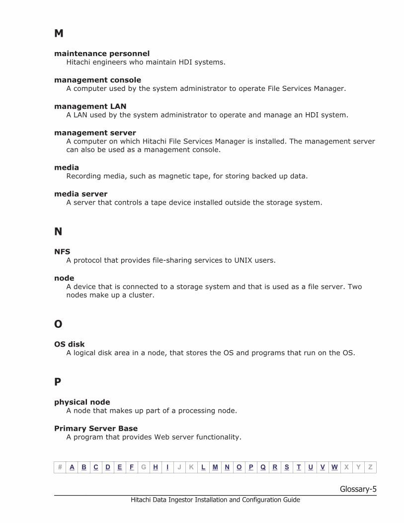
M
maintenance personnelHitachi engineers who maintain HDI systems.
management consoleA computer used by the system administrator to operate File Services Manager.
management LANA LAN used by the system administrator to operate and manage an HDI system.
management serverA computer on which Hitachi File Services Manager is installed. The management servercan also be used as a management console.
mediaRecording media, such as magnetic tape, for storing backed up data.
media serverA server that controls a tape device installed outside the storage system.
N
NFSA protocol that provides file-sharing services to UNIX users.
nodeA device that is connected to a storage system and that is used as a file server. Twonodes make up a cluster.
O
OS diskA logical disk area in a node, that stores the OS and programs that run on the OS.
P
physical nodeA node that makes up part of a processing node.
Primary Server BaseA program that provides Web server functionality.
# A B C D E F G H I J K L M N O P Q R S T U V W X Y Z
Glossary-5Hitachi Data Ingestor Installation and Configuration Guide
processing nodeA logical group made up of nodes. If nodes are set up in a cluster, the cluster is treatedas a processing node.
Q
quotaThe maximum block space and maximum number of inodes available to a user. In anHDI system, limits can be set and managed for each file system or each directory.
R
resource groupA management unit used to manage multiple resources (such as NFS share settings,CIFS share settings, file system information, and virtual IP address information) as agroup. Services can be started and stopped for each resource group. If an error occurs,failover is performed for each resource group.
S
scan serverA server that scans, via a LAN, CIFS-shared data in an HDI system for viruses.
ShadowImageA program for replicating user data within a storage system, without using a host.
subtree quotaA quota set for a directory and the users and groups of that directory.
system administratorA user who manages an HDI system. The system administrator sets up an HDI systemand monitors system operations and error information.
system LUA collective term for the OS disks and the cluster management LU.
T
tape deviceA device for storing multiple types of storage media.
# A B C D E F G H I J K L M N O P Q R S T U V W X Y Z
Glossary-6Hitachi Data Ingestor Installation and Configuration Guide

targetA unit used to manage multiple LUs as one group so that a node can uniquely recognizethe LUs of a storage system.
TrueCopyA program for replicating user data between two storage systems, without using a host.
trunkingA technology used to create a virtual network interface from a group of ports. HDIallows you to configure a network by using virtual network interfaces that areassembled by using trunking.
U
Universal ReplicatorA program that asynchronously reproduces user data between two storage systemswithout transferring the data via a host.
user LUA generic term for an LU that is assigned to a node and that stores user data such asfile system information. A user LU is also called a device file or an LU (excluding thesystem LU).
user LUNA management number assigned to each user LU. A user LUN is also called a device filenumber.
user mappingThe process of assigning a user ID and group ID to a user registered in a domaincontroller when the user accesses a CIFS share.
V
virtual IP addressAn IP address used by a user when connecting to a service running on a resourcegroup. By using a virtual IP address, the user can continue to use the service even if anerror occurs on a node and the resource group fails over to the other properly-runningnode.
volume groupAn area that consists of one or more LUs that have been grouped together by a volumemanager. A volume group is made up of one file system.
# A B C D E F G H I J K L M N O P Q R S T U V W X Y Z
Glossary-7Hitachi Data Ingestor Installation and Configuration Guide

volume managerFunctionality for volume management. In the HDI system, LVM is used as the volumemanager. This functionality enables you to create volume groups combining LUs and tocreate logical volumes out of volume groups.
W
WORMAn abbreviation for "Write Once, Read Many". The WORM status indicates that datacannot be modified. A file whose status is changed to the WORM status is called aWORM file, and a file system in which any files can be changed to a WORM file is calleda WORM file system.
# A B C D E F G H I J K L M N O P Q R S T U V W X Y Z
Glossary-8Hitachi Data Ingestor Installation and Configuration Guide

Index
Symbols
/etc/hosts file 5-7
A
access controlNDMP server 5-7
account.lock.num 7-39account.lock.system 7-39ADAM 3-22administrative privilege
executing command 3-10authorization group 7-35
B
backing updatabase of management server 7-107
backupincremental backup 5-5recommended time 5-5
backup functionalityoverview 5-2
backup server 2-6
C
cache residency 6-5cascaded trunking 2-18changing
host name of management server 7-126IP address of management server 7-126user mapping method 4-13
CIFS sharebefore using 4-57network configuration 2-11
clientusing file systems 4-85
clustermanagement server configuration 3-9
cluster configurationinstalling Hitachi File Services Manager on anduninstalling Hitachi File Services Manager frommanagement server running in 7-15
cluster management LU 4-77command
executing with administrative privilege 3-10
D
DACL 4-33tape device
environment settings 3-39Device Manager 2-3DHCP server 2-5
environment settings 3-41disconnecting
management server network 7-130DNS server 2-4
environment settings 3-42domain controller 2-4
environment settings 3-29
E
encryption
Index-1Hitachi Data Ingestor Installation and Configuration Guide

notes 4-23environment setting
Hitachi File Services Manager 7-86environment settings
DHCP server 3-41DNS server 3-42domain controller 3-29KDC server 3-30LDAP server 3-19management console 3-11management server 3-5NIS server 3-18NTP server 3-34RADIUS server 3-31scan server 3-35SMTP server 3-41SNMP manager 3-32tape device connected node via SAN 3-39
error information 4-77node 4-78
estimating capacitybackup media 5-3
executing node 3-9external authentication server 7-35external authorization server 7-35external server 2-2, 2-6
F
file share 4-56file system 4-19
creating a volume group 4-20file systems
using CIFS bypass traverse checking 4-43using single instancing to reduce used capacity4-42
file version restore functionality 6-6past version directory 6-6
Firefoxsetting 3-17
flat model 7-43front-end LAN 2-7FTP server 2-5
G
grace period 4-47
H
hard limit 4-47hardware configuration 2-2hcmdsldapuser command
when authentication method is Kerberos 7-77HCP 1-4HDI 1-2
hardware configuration 2-2network configuration 2-7system configuration 2-1
hierarchical structure model 7-42Hitachi Command Suite Common Component 2-3Hitachi Content Platform 1-4Hitachi Data Ingestor 1-2
overview 1-2Hitachi File Services Manager 2-2
environment setting 7-86installing and uninstalling 7-2installing and uninstalling (if managementserver is running in cluster configuration) 7-15prerequisites for installing 7-12starting 7-31stopping 7-31
Hitachi MIB objectsobtaining definition file 3-33
Hitachi Storage Navigator Modular 2 2-3hnasm.common.logger.loglevel 7-86hnasm.common.logger.maxfilenumber 7-87hnasm.common.logger.maxfilesize 7-87hnasm.common.logger.syslog.loglevel 7-87hnasm.model.refresh.screen.license 7-88home-directory-roaming functionality 6-28
I
importingabout importing data from other file servers4-80points to check 4-82system configuration 4-81
incremental backup 5-5differential-data backup 5-5incremental-data backup 5-5
installingHitachi File Services Manager 7-2Hitachi File Services Manager (if managementserver is running in cluster configuration) 7-15
Internet Explorersetting 3-14
Index-2Hitachi Data Ingestor Installation and Configuration Guide

J
jssecacerts 7-98
K
KDC server 2-4environment settings 3-30
Kerberos authenticationhcmdsldapuser command 7-77
L
LDAP server 2-5environment settings 3-19notes 3-20
limitgrace period 4-47hard limit 4-47soft limit 4-47
link aggregation 2-17link alternation 2-17local data encryption 4-23
M
maintenancedisconnecting tape device 3-41management server 7-107replacing tape device 3-40
management console 2-2Firefox 3-17Internet Explorer 3-14requirements 3-11
management LAN 2-7management server 2-2
adjusting time 7-129backing up database 7-107changing host name 7-126changing IP address 7-126disconnecting network 7-130maintenance 7-107migrating 7-112migrating database 7-120requirements 3-5restoring database 7-107
mediaestimating capacity 5-3
media server 2-6migrating
database of management server 7-120management server 7-112
monitoring systemsSNMP 4-79
N
NDMP functionalitydata to be backed up or restored 5-5limitations on the functionality of the backupmanagement software 5-9offline backup 5-3overview 5-2using 5-2
NDMP serveraccess control 5-7
network configuration 2-7trunking 2-17using both VLAN and trunking 2-24using CIFS share 2-11using VLAN 2-22
NFS sharebefore using 4-56
NIS server 2-4node 1-2
error information 4-78notes
encryption 4-23LDAP server 3-20on managing 4-3on using ADAM 3-22on using file system from CIFS client 4-86on using file system from NFS client 4-85on using OpenLDAP 3-20on using Sun Java System Directory Server 3-21
NTP server 2-4environment settings 3-34
O
offline backup 5-3OpenLDAP 3-20OS
forcibly stopping B-2starting B-2
OS disk 4-76
Index-3Hitachi Data Ingestor Installation and Configuration Guide

overviewNDMP functionality 5-2
P
partially blocked 4-5password.check.userID 7-37password.min.length 7-37password.min.lowercase 7-37password.min.numeric 7-37password.min.symbol 7-37password.min.uppercase 7-37points to check
importing from another file server 4-82power button B-2
how to use B-1power indicator B-2power lamp B-2power lamp switch B-2
how to use B-1precaution
WORM file system 4-42proxy server 2-5
Q
quotasetting 4-44
quota monitoring time 4-47
R
RADIUS server 2-4environment settings 3-31
real-time virus scanning 4-60recall 6-5registering
tape drive 3-39relaying device 2-5requirements
management console 3-11management server 3-5
resource group 4-6restore
recommended time 5-5restoring
database of management server 7-107retention period 4-40
RID 4-12
S
scan server 2-5setting
quota 4-44SID 4-9SMTP server 2-5
environment settings 3-41SNMP 4-79SNMP manager 2-4
environment settings 3-32soft limit 4-47standby node 3-9starting
Hitachi File Services Manager 7-31stdCoreTrap 3-33stdEventTrapError 3-32stdEventTrapFatalError 3-32stdEventTrapInformation 3-32stdEventTrapWarning 3-32stdQuotaTrapFSDetailSuppress 3-33stdQuotaTrapFSLimitExceeded 3-33stdQuotaTrapFSSoftLimit 3-33stdQuotaTrapFSSubtreeDetailSuppress 3-33stdQuotaTrapFSSubtreeLimitExceeded 3-33stdQuotaTrapFSSubtreeSoftLimit 3-33stdQuotaTrapFSSubtreeSummary 3-33stdQuotaTrapFSSummary 3-33stdTrapNotice 3-32Storage Navigator 2-2striping function 4-28stub file 6-3subtree quota 4-44Sun Java System Directory Server 3-21system administrator
account unlock 7-40system configuration 2-1
HCP linkage 2-24importing files from other file servers 4-81
system LU 4-76system settings 4-76system settings file 4-77
T
tape device 2-6
Index-4Hitachi Data Ingestor Installation and Configuration Guide

tape driveregistering 3-39unregistering 3-40
timeadjusting management server 7-129
trunkingusing with VLAN 2-24
U
uninstallingHitachi File Services Manager 7-2Hitachi File Services Manager (if managementserver is running in cluster configuration) 7-15
unlocking system administrator account 7-40unregistering
tape drive 3-40user mapping 4-9
changing method 4-13domains that allow access to HDI system 4-9method 4-11
user.conf 7-39user.properties
changing the update setting of the licenseinformation 7-88log file settings 7-86
using CIFS bypass traverse checking 4-43using trunking
network configuration 2-17
V
version management 6-6virtual IP address 4-7VLAN
network configuration 2-22using with trunking 2-24
VLAN ID 2-23volume group 4-19
creating 4-20
W
Web browsermanagement console 3-13
WINS server 2-4WORM file 4-40WORM file system 4-40
precaution 4-42
Index-5Hitachi Data Ingestor Installation and Configuration Guide

Index-6Hitachi Data Ingestor Installation and Configuration Guide

Hitachi Data Ingestor Installation and Configuration Guide

Hitachi Data Systems
Corporate Headquarters2845 Lafayette StreetSanta Clara, California 95050-2639U.S.A.www.hds.com
Regional Contact Information
Americas+1 408 970 [email protected]
Europe, Middle East, and Africa+44 (0)1753 [email protected]
Asia Pacific+852 3189 [email protected]
MK-90HDI002-18