ho lok ping wilson - cityucs - cityu cshwchun/fyp/2004/ho lok ping wilson.pdffigure 12...
TRANSCRIPT

CS6510 Dissertation
User Guided Behavior-based Robotic System
Final Report
Submitted
To
Dr Andy Chun, Associate Professor
Department of Computer Science City University of Hong Kong
By
Ho Lok Ping, Wilson
(Student ID: 50355544)
Date: 7 December 2004

1
ACKNOWLEDGEMENTS
Academic work is not achieved by a mere individual; rather, it is the art of
communication and collaboration. When I first joined the MSCS course offered by the
City University of Hong Kong, I neither imagined that I would write a thesis about
robotics, nor even dreamt of making our real robots. However, it all happened after
subsequent years by meeting people and working with people. Now I am so grateful
for what I have done during my academic years, and what I have done for my thesis
work. Therefore, I would like to express my gratitude to the following people for their
support and assistance in pursuing my academic career.
Firstly, I would like to thank Dr. Andy Chun for giving me an opportunity to work on the
robotic project. He has provided me with everything that I need to complete my thesis
work and my academic career including the support for invaluable academic and
technological advice.
Similarly, I cannot help thanking Mr. Johnny Lung from the Robotics Laboratory of the
City University of Hong Kong for being kind enough to offer me an opportunity to visit
their robotic development works using Lego Mindstorms. I thank my friend and fellow
students, particularly, Mr. Albert Chung, who also work in another robotic project.
Without his help and collaboration, my academic pursuit would not have ended
successfully.
Finally, I would like to thank my family who will ever support me in anything I need.

2
Table of Contents
ACKNOWLEDGEMENTS ............................................................................................1 LIST OF PICTURES.....................................................................................................4 I. INTRODUCTION.......................................................................................................6
1.1 Background.....................................................................................................6 1.2 Objectives .......................................................................................................6 1.3 Usefulness of the Topic...................................................................................7 1.4 Potential Outcome ..........................................................................................7
II. RELATED WORK.....................................................................................................9 2.1 Evolution Robotics™ Robot Control Centre (RCC)........................................9 2.2 Robots by Other Robotics Company ..............................................................9 2.3 Robot Waitress..............................................................................................10
III. SYSTEM MODELING AND STRUCTURE ........................................................... 11 3.1 Robot Control Architectures.......................................................................... 11 3.2 Incremental Design .......................................................................................13 3.3 System Overview ..........................................................................................13 3.4 Concurrent Design ........................................................................................14 3.5 Static Structure..............................................................................................14 3.6 Main Class Diagrams....................................................................................15 3.7 System Architecture ......................................................................................17 3.8 Simple Robotic Behaviors.............................................................................19 3.9 Evolution Robotics™ ER1 Robot..................................................................21
IV. METHODOLOGY AND ALGORITHMS USED IN THE DESIGN / IMPLEMENTATION OF THE SYSTEM......................................................................23
4.1 Client / Server Architectures .........................................................................23 4.2 Real-time Remote Access Control................................................................25 4.3 Socket Programming ....................................................................................25 4.4 Hardware Design ..........................................................................................25
4.4.1 Robot Kit .............................................................................................26
4.4.2 Camera, IR sensors, Gripper and Miscellaneous ..............................28
4.4.3 Survey.................................................................................................29
4.5 Software ........................................................................................................29
4.5.1 Image Recognition..............................................................................30
4.5.2 Sound Recognition .............................................................................30

3
4.5.3 Obstacle Avoidance ............................................................................30
4.5.4 Navigation Model ................................................................................30
4.6 Total Cost for the Robot Development..........................................................34
4.6.1 Hardware ............................................................................................34
4.6.2 Software..............................................................................................34
4.7 Software Design............................................................................................35
4.7.1 Robot Control Architecture .................................................................35
4.7.2 Communication Protocol ....................................................................37
4.7.3 Strabo Path Translator........................................................................37
4.7.4 Path Editor Converter .........................................................................38
4.7.5 ER1 Robot Server Program................................................................39
4.7.6 Robotic Command Centre ..................................................................39
V. ANALYSIS OF ALGORITHM / SYSTEM................................................................44 5.1 ER1 Robot Prototype ....................................................................................44 5.2 Limitations and Possible Solution .................................................................44 5.3 Experimental Setup.......................................................................................46 5.4 Experimental Results ....................................................................................48 5.3 Discussion.....................................................................................................51
VI. CONCLUSIONS....................................................................................................54 VII. REFERENCES ....................................................................................................55 APPENDICES ............................................................................................................59
Appendix A –Project Planning – key dates .........................................................59 Appendix B – Robotic Command Centre API .....................................................60

4
LIST OF PICTURES
Figure 1 Robot Waitress - Mei Mei.............................................................................10
Figure 2 Concurrent Design .......................................................................................14
Figure 3 Package Diagram ........................................................................................15
Figure 4 Class Diagram - Network.............................................................................16
Figure 5 Class Diagram - State ..................................................................................16
Figure 6 Class Diagram - Command .........................................................................17
Figure 7 Class Diagram - Interface ............................................................................17
Figure 8 Layered System Architecture.......................................................................19
Figure 9 Module Diagram...........................................................................................20
Figure 10 Subsumption Network Design Diagram - A Basic Obstacle Avoidance
Robot...................................................................................................................20
Figure 11 Evolution Robotics™ Robot Control Centre ..............................................21
Figure 12 Stimulus-Response Diagram for our subsumption-based Robot Waiter...22
Figure 13 Communication Diagram of ER1 Robot and Robotic Command Centre ..24
Figure 14 ER1 Robot from Evolution Robotics™ Holding a Can of Coffee...............26
Figure 15 ER1 Robot’s Gripper Arm ..........................................................................26
Figure 16 Customized ER1 Robot .............................................................................27
Figure 17 Logitech® QuickCam® Pro 4000 (Left), IR Sensors (Centre), Gripper (Right)
............................................................................................................................28
Figure 18 Bundled WebCam......................................................................................29
Figure 19 StraboTM Pathfinder main screen...............................................................32
Figure 20 Dijkstra path searches ...............................................................................33

5
Figure 21 A* (Astar) path searches ............................................................................33
Figure 22 Connection Screen ....................................................................................40
Figure 23 Path Editor Screen.....................................................................................40
Figure 24 Behavior Screen ........................................................................................41
Figure 25 Remote Control Screen .............................................................................42
Figure 26 Camera Setting Screen..............................................................................42
Figure 27 Notes Screen .............................................................................................43
Figure 28 About Screen .............................................................................................43
Figure 29 Problem of Holding Paper-made Coffee Cup ............................................45
Figure 30 Rubber-made Coffee Cup is the minimum requirement of the holding media
............................................................................................................................45
Figure 31 Canned Coffee do not pose any problem with the ER1 Gripper ...............45
Figure 32 Partial Enviroment Setup ...........................................................................47
Figure 33 Partial Environment Setup - StraboTM........................................................48
Figure 34 “Right Arrow” Sign for Homing ...................................................................50
Figure 35 "Home" Sign for Homing ............................................................................50
Figure 36 ER1 Robot with Torch Light in the Dark.....................................................51
Figure 37 Capture Image of Front vVew from ER1 with Torch Light .........................51
Figure 38 NorthStar Detector (Left) & NorthStar IR Projector (Right) ........................52
Figure 39 NorthStar in Operation ...............................................................................53

6
I. INTRODUCTION
1.1 Background Traditionally, robot has helped people to finish a lot of pre-defined and autonomous
job. At the turn of the 21st century, implementation of different kinds of practices has
occurred. Until recently, robot has even performed a more solid part in space
exploration which is extremely dangerous for human in this unknown environment. In
view of this, we would like to get a more understanding to the robotic topics. We know
that the development of the intelligent robots are rather slow compare with another
technology, like the increase of the speed of micro-processor doubled every 18
months, etc. However, we hope that the knowledge we gained and the experience we
learned can be significant in the later development and exploration of robotic topics
for our next generation.
1.2 Objectives In this project, we would like to build a robot which leverages behavior-based
approached with user-friendly guided feature. In so doing, we have examined two
consumer robots which are of different brands, the first one is the Lego®
MindstormsTM Robot and the other one is the ER1 Robot by Evolution Robotics™, Inc,
and both will react with the environment using different pre-defined behaviors
respectively. With this hand-on experience, we are going to make a more formal
robotic project – a robot with localization system using Evolution Robotics’ ER1 Robot
as the framework.

7
1.3 Usefulness of the Topic This paper will leverage modern technologies to fulfill the requirement. Wireless
802.11g network will be the foundation between the Robotic Command Centre and
the ER1 Robot itself. Different robotic behaviors will be examined with the interaction
among different behaviors. Last but not the least, robotic localization and path-finding
abilities will be incorporated in the robot to build a semi-autonomous robot.
Developing a computer program is generally a time-consuming task, and developing
a robot control program to deal with a machine embedded in the physical world is
even more challenging than the common computer programs that only deal with
abstract entities. To evaluate the performance of the tasks specified in a program, no
matter what the tasks are, the software must be integrated into a robot and tested in
the physical environment. Therefore, the robot, the program, and perhaps the
environment must be arranged for the complete evaluation.
1.4 Potential Outcome We will create a prototype of a robot which can leverage among different behaviors
with remote control facility. The software will make use of Socket programming
technique, Microsoft® Visual C#, Microsoft® Visual Basic .NET, Strabo PathfinderTM
by Fusion Robotics, and some other open source components if available, etc. A
proposed framework is to design and build a robotic system that is easy to manipulate
and easy to expand for future study.
In the development of the robot, we consider roughly two kinds of tasks,
safety-oriented tasks and navigation-oriented tasks. The safety-oriented tasks include

8
behaviors such as collision detection to ensure collision-free navigation for the robot.
This group of behaviors generally exhibits behaviors in a reactive manner. The
navigation-oriented tasks, on the other hand, involve relatively higher level tasks
compared to the safety-oriented tasks. The behaviors such as environmental
mapping and route planning are typical examples of the navigation-oriented tasks.
There is no choice over which group of tasks is more important than the other.
However, the degree of autonomy a robot may affect the prioritization of tasks. For
example, developing a semi-autonomous robot usually leaves high-level decisions to
the robot and thus prioritizes the safety-oriented tasks. The thesis is founded on an
aspiration of building a semi-autonomous intelligent robot. Therefore, the
safety-oriented tasks are considered as the first priority. A mobile robot is used as a
test bed in the structured indoor environment for experimenting with the robotic
system with localization and path-finding abilities.

9
II. RELATED WORK
Thousands of robot related work have done in the past decades, AI, behaviors,
mechanical robot arm, chess opponent, robot architecture, simulation, circuits, design,
implementation, etc. However, consumer-level robot with localization and path-finding
facilities, and related work is very difficult to find.
2.1 Evolution Robotics™ Robot Control Centre
(RCC) Evolution Robotics’ Robot Control Centre - Although it is easy to use, it lacks
localization and path-finding facility which hinders its overall function and hinder the
ER1 Robot to a very elementary level which limits its potential. That is also one of the
objective for building the Robotic Command Centre for ER1 Robot.
2.2 Robots by Other Robotics Company Other research projects by ActivMedia Robotics, LLC, such as some developed using
AmigoBotTM which is of high cost, normally more than HKD30,000 with embedded
system. In view of this, we want to lower the cost for the robot development taken into
consideration for the benefit of the public at large, our target price is HKD20,000.
Moreover, they are more for the researchers than for the consumers. Their systems
developed are too difficult to change without large code re-built which is a major
barrier for the common users.

10
2.3 Robot Waitress Three is a robot current under experiment which I would also like to implement is a
waitress robot in Chinese dress, called "Mei Mei,", carries a couple of glasses of
water to a customer's table outside Tokyo. The robot moves to tables using an
infrared sensor and serves water and delivers menus to customers with a bow and
words of welcome as Figure 1 shows1.
Figure 1 Robot Waitress - Mei Mei
As can be seen from the above a robot waitress "Mei Mei," can carry a couple of
glasses of water to a customer's table outside Tokyo. The robot moves to tables using
an infrared sensor and serves water and delivers menus to customers with a bow and
words of welcome. However, we would like to build a robotic system which can not
only delivery a cup of coffee to the client’s table which “Mei Mei” does and can also be
easily modified by common users with changing environment with localization and
path-finding abilities.
1 TLC LifeUnscripted, 2003,
http://tlc.discovery.com/convergence/robosapiens/photos/photos_zoom6.html

11
III. SYSTEM MODELING AND STRUCTURE
3.1 Robot Control Architectures Robotic Control in the Architectural design, including the Deliberative Architecture,
Reactive Architecture, Behavior-based Architecture (mainly Subsumption
Architecture) would be studied.
There are three broad types of robot control architectures (Mataric (1997))2: [1]
• Deliberative
• Purely Reactive
• Hybrid
• Behavior-based
In short, deliberative strategies use a centralized model of the environment to plan
complete paths to goals. These are typically done prior to the robot acting and may be
even done off-line. These strategies can be slow to generate plans and brittle should
the environment change (model updating and replanning is necessary, so action may
be delayed). For uncertain environments (due to sensor or effector noise, or a
changing environment) constant replanning may be necessary.
2 Matt Mitchell, "Robot Control",
http://www.csse.monash.edu.au/courseware/cse3475/Lectures/Module3/module.html, 2003

12
Purely reactive are stimuli/response type architectures. These are typically
pre-programmed condition-actions. Since there is no central world model, there is no
planning or internal search for solution paths.
Hybrids combine aspects of both purely reactive and purely deliberative strategies.
One approach is to have a reactive low level controller and a high-level deliberative
planner. Often the low level controller ensures the immediate safety of the agent,
while the high level planner determines paths to goals. One type of hybrid approach is
the Behavior-based approach. These are more complex than the simple
condition/actions or lookup tables of pure reactive systems. One such Behavioral
architecture builds upon the reactive subsumption architecture3.
The Subsumption Architecture was proposed by Brooks (1986). He argues that many
developers of robots use a model that runs from inputs to outputs though stages of
modeling, planning and task execution. This type of architecture involves a single
synchronous thread of execution from input to output. The modules in such a system
are based on functional components in the system (e.g. planning component,
mapping component). Brooks proposed that robot control systems should be instead
decomposed according to task achieving Behaviors or competencies. This means
instead of viewing processing a sequence of processes moving from inputs to outputs,
control is seen as a stack of competencies achieved through layers of control4. [2] [3]
3 Karl Williams, “Insectronics”, Mc Graw Hill, pp.127-137, 2003
4 Ronald C. Arkin, “Behavior-based Robotics”, The MIT Press, 1998

13
3.2 Incremental Design
The ultimate goal of our robotic experiments is to build a robot which can be used in
the future study of a robotic system. In order to build such a robust and compatible
program, we must build up the program as a complete system with a set of complete
behaviors, which enables the robot to be tested in the real world environment.
Rodney A. Brooks at the MIT AI Laboratory suggested in his famous article that
building complex robots (he calls creatures) which coexist in the world with humans
must be incrementally built in the same manner as biological evolution (Brooks 1991).
For instance, a single-cell amoeba which wanders the world without any goal and a
human who exhibits intelligent behaviors are both complete biological systems
although there is a difference in the degree of intelligence. During the astronomical
time span, biological evolution on earth started from the lower intelligence of amebas
and now has ended up with the human level intelligence up to this point. Brooks’ idea
of building a robot mimics the process of evolution. The concept of this incremental
design helps the entire project of building an intelligent system to advance toward to
the goal steadily one step at a time.
3.3 System Overview
The Robotic Command Centre must be able to open and close network connections,
send command sequences, track and display images, etc based on user input
through a graphical user interface.

14
3.4 Concurrent Design
The Robotic Control Centre will have three parts that can run concurrently (Figure 2):
• Network – sends and receives data from the network
• Interface – receives input from the user
• Control – tracks robot state, organizes actions of other parts
Each of these components will run in their own thread, allowing each to continue
functioning without waiting for other components.
Figure 2 Concurrent Design
Each of these parts can be characterized as a package that implements a specific
aspect of the software. Within each of these packages there will be one or more
classes to implement the required functionality.
3.5 Static Structure
As mentioned in the System Overview, the software will be separated into three
15
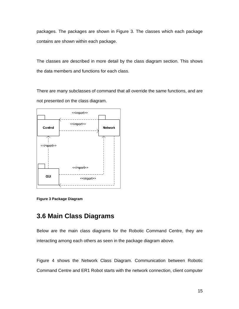
packages. The packages are shown in Figure 3. The classes which each package
contains are shown within each package.
The classes are described in more detail by the class diagram section. This shows
the data members and functions for each class.
There are many subclasses of command that all override the same functions, and are
not presented on the class diagram.
Figure 3 Package Diagram
3.6 Main Class Diagrams
Below are the main class diagrams for the Robotic Command Centre, they are
interacting among each others as seen in the package diagram above.
Figure 4 shows the Network Class Diagram. Communication between Robotic
Command Centre and ER1 Robot starts with the network connection, client computer
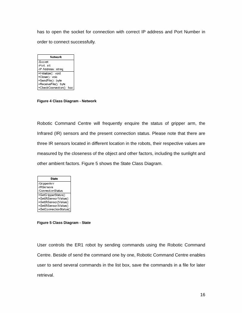
16
has to open the socket for connection with correct IP address and Port Number in
order to connect successfully.
Figure 4 Class Diagram - Network
Robotic Command Centre will frequently enquire the status of gripper arm, the
Infrared (IR) sensors and the present connection status. Please note that there are
three IR sensors located in different location in the robots, their respective values are
measured by the closeness of the object and other factors, including the sunlight and
other ambient factors. Figure 5 shows the State Class Diagram.
Figure 5 Class Diagram - State
User controls the ER1 robot by sending commands using the Robotic Command
Centre. Beside of send the command one by one, Robotic Command Centre enables
user to send several commands in the list box, save the commands in a file for later
retrieval.

17
Figure 6 Class Diagram - Command
The interface between the Robotic command Centre and the ER1 Robot is the
Graphical User Interface. Carefully organized and user-friendly interface created
under the Microsoft® .NET framework has enhanced usability for users. As Figure 7
shows the different elements in the interface.
Figure 7 Class Diagram - Interface
3.7 System Architecture
The system architecture is an abstract design that organizes the system components.
In the recent robotic literature, most autonomous robots employ a layered
architecture. There are roughly two types in decomposing the system into layers,
functional-based layers and behavior-based layers. Nowadays, the trend in layered
architecture is Brooks’ subsumption architecture, in which the system is decomposed
into task-oriented behaviors (Brooks 1986). In the subsumption architecture, the
independent behaviors exercise their tasks (from sensing to acting) in parallel.
Therefore, the failure of one behavior does not interrupt the entire system execution.
The independence of behaviors also gives the capability of easily adding more

18
behaviors to the system in an incremental manner. Each behavior can either
suppress or inhibit the input/output of other behaviors to interact with the environment,
which causes the emergence of a high-level intelligent behavior without giving the
robot specific instructions of what to do to achieve that particular behavior. Also, the
absence of a central reasoning protocol, no symbolic representation of the world
model, and the direct control of actuators by a behavior are well-known distinctive
characteristics of the subsumption architecture (Brooks 1991). Although each
behavior is independent, the ability of influencing another behavior eventually makes
the system very complicated, and adding another behavior may thus require
enormous efforts. In addition, because of the emergent characteristic of
behavior-based systems, the complexity in analyzing the result of emergent
behaviors may also cause a problem in modifying and configuring the system. The
classical hierarchical approach had been, on the other hand, dominating the robotic
trend for decades until the rise of the subsumption architecture. Unlike the
behavior-based decomposition of the subsumption architecture, the traditional
layered architecture decomposes the system into functional modules such as sense,
plan, and act. This type of architecture has the advantage of having easily separable
functional modules that are associated with an intuitive paradigm in designing the
hierarchical architecture. However, it is often noted that the system is hardly
modifiable once the hierarchy is defined since the functionality of modules is limited to
contribute to certain behaviors (Liscano et al. 1995).

19
OS & HARDWARE
ARCHITECTURE
APPLICATIONS
NAVIGATIONVISION INTERACTION Client DevelopedSoftware
Robot Control CentreAPI
Figure 8 Layered System Architecture
The robotic system architecture used in this thesis (Figure 8) consists of two layers
taking the advantage of the former two types. Basically, the system has several
behavior-based like structure. Each structure is composed of two functional layers,
Hardware Layer and Component Layer. The Hardware Layer is a collection of
modules communicating with the robot’s hardware devices such as a camera,
infrared sensors and motors. The Hardware Layer is implemented with Microsoft®
Visual C# .NET since the ER1 kit is provided with the development environment that
specifies the language. The SDK (Software Development Kit) already contains
libraries to help in accessing the hardware components of the robot, which reduces
the amount of redundant effort. This layer functions as a bridge between the
upper-level layer and the hardware. The Component Layer contains the intermediate
functional modules which constitute the higher-level behaviors. The Component
Layer is implemented with Microsoft® Visual C#.
3.8 Simple Robotic Behaviors Below is an example of a common robot using the Subsumption Architectures.

20
avoid obstacle
move forward
Sensors Motors
Figure 9 Module Diagram
The preliminary design of the robot implement forward movement, when there is
external stimulus encountered, like hit by either left or right touch sensors, it will turn
to the opposite direction. This is a simple model and can be used in robot like Lego®
MindstormsTM Robot, so there are only 2 modules formulated as Figure 9 shows.
collision resolve
wander move forward
turn right
turn left
s
s
s
s
left touch sensor
right touch sensor
Figure 10 Subsumption Network Design Diagram - A Basic Obstacle Avoidance Robot
Figure 10 shows the augmented finite state machines (AFSM) of the basic robotic
design, it will be further elaborate as follow:
21
• Wander AFSM: It is the first part of the robot movement until other stimulus has changed it preliminary direction.
• Move Forward AFSM: The robot will move forward except it is suppressed by either Left or Right touch sensors.
• Turn Left / Turn Right AFSM: It will suppress the move forward AFSM and move the robot in reverse direction when either Turn Left or Turn Right AFSM has been triggered.
• Collision Resolve AFSM: it takes inputs from the left and right touch sensors and determines which sensor is touched. It will trigger the reverse direction of the robot movement.
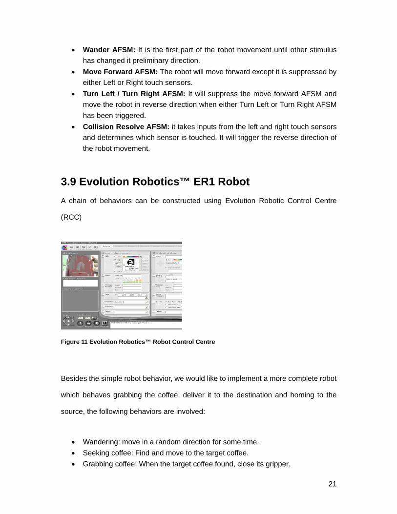
3.9 Evolution Robotics™ ER1 Robot A chain of behaviors can be constructed using Evolution Robotic Control Centre
(RCC)
Figure 11 Evolution Robotics™ Robot Control Centre
Besides the simple robot behavior, we would like to implement a more complete robot
which behaves grabbing the coffee, deliver it to the destination and homing to the
source, the following behaviors are involved:
• Wandering: move in a random direction for some time. • Seeking coffee: Find and move to the target coffee. • Grabbing coffee: When the target coffee found, close its gripper.

22
• Seeking required table: Locate the table for coffee delivery. • Coffee delivery: Put down the coffee in the designated table. • Homing: Return to the source (starting point).
Figure 12 illustrates the Stimulus-Response (SR) diagram for this set of behaviors.
Like the previous example, priority-based arbitration is the coordination, and the robot
is executing only one behavioral rule at any time. Note in particular that when the
robot senses the attractor, wandering is suppressed and when the attractor is
grabbed, homing then suppresses grabbing, it is the mechanism of subsumption
architecture.
seek coffee
grab coffee
wander
sdeliver coffee
seek required table s
homing
s
s
s
Figure 12 Stimulus-Response Diagram for our subsumption-based Robot Waiter
These are the main system modeling and structures, the methods and
implementation details for the robots are going to be described in the next section.
23
IV. METHODOLOGY AND ALGORITHMS USED
IN THE DESIGN / IMPLEMENTATION OF THE
SYSTEM
The main objectives of the project are to study the current technologies in robotic
arena and to build a prototype mobile robot. The prototype should feature some forms
of behavior, such as localization, path-finding and homing, etc.
We have examined the following robots in our project: the Lego® MindstormsTM Robot
and the ER1 Robot from Evolution Robotics™. They can both use current high level
language to further enhance the robotic behaviors to suit one's particular need, such
as Microsoft® Visual C#, Microsoft® Visual Basic .NET, Python, etc.
4.1 Client / Server Architectures
The term client/server was first used in the 1980s in reference to personal computers
(PCs) on a network. The actual client/server model started gaining acceptance in the
late 1980s. The client/server software architecture is a versatile, message-based and
modular infrastructure that is intended to improve usability, flexibility, interoperability,
and scalability as compared to centralized, mainframe, time sharing computing.
A client is defined as a requester of services and a server is defined as the provider of
services. A single machine can be both a client and a server depending on the
24
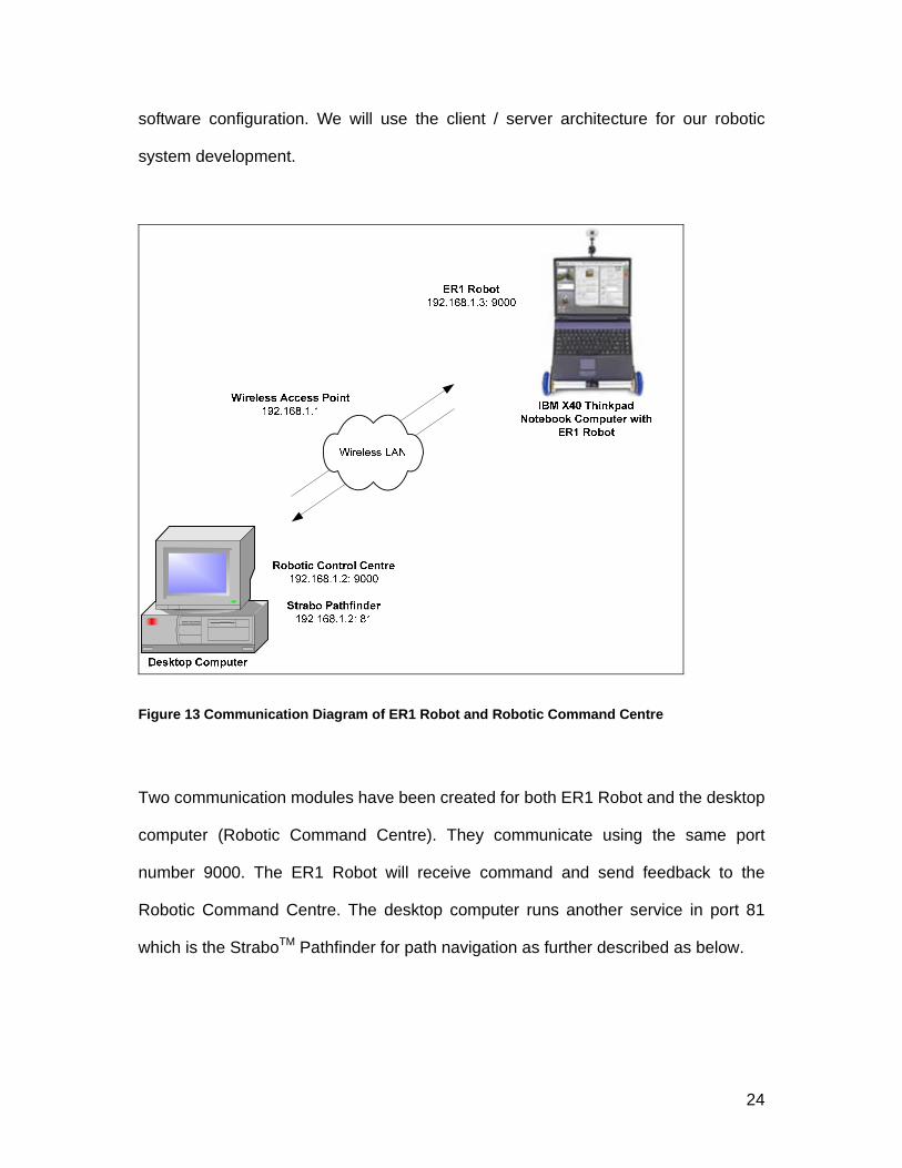
software configuration. We will use the client / server architecture for our robotic
system development.
Figure 13 Communication Diagram of ER1 Robot and Robotic Command Centre
Two communication modules have been created for both ER1 Robot and the desktop
computer (Robotic Command Centre). They communicate using the same port
number 9000. The ER1 Robot will receive command and send feedback to the
Robotic Command Centre. The desktop computer runs another service in port 81
which is the StraboTM Pathfinder for path navigation as further described as below.

25
4.2 Real-time Remote Access Control
With the creation of the client software (Robotic Command Centre) and the server
program located in the ER1 Robot, the real-time remote-access control can be
achieved. Client can send the robot command one by one to the server (ER1 Robot)
and the server will enforce the action accordingly.
4.3 Socket Programming
To develop client / server applications in the TCP/IP domain, we will make use of
socket programming in which the client and server will communicate among their
same assigned sockets. Its fundamental concepts include network addressing, well
known services, sockets and ports.
4.4 Hardware Design At first glance, ER1 Robot is just a robot skeleton, it seems to be nothing more than
that, once it has been assembled with a notebook computer, and it can start working.
The attractive point for using ER1 Robot but not others is it is easy to build and can
make use of existing notebook computer as its brain.

26
Figure 14 ER1 Robot from Evolution Robotics™ Holding a Can of Coffee
It comes with several peripherals: One camera and two motors. If we purchase an
expansion kit, there will also have a gripper arm and three more Infra-red sensors for
better obstacle avoidance navigation.
Figure 15 ER1 Robot’s Gripper Arm
4.4.1 Robot Kit The hardware used in this experiment is a commercial robot kit called the ER1 Robot
by evolution robotics™. The robot kit includes the control software, aluminum beams
and plastic connectors to build a chassis, two assembled scooter wheels powered by
two stepper motors, one 360 degree rotating caster wheel, a power module, a battery
(12V 5.4A), and a web-camera. The experimental robot also carries additional
27
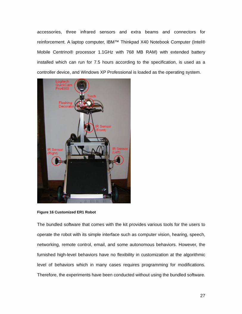
accessories, three infrared sensors and extra beams and connectors for
reinforcement. A laptop computer, IBM™ Thinkpad X40 Notebook Computer (Intel®
Mobile Centrino® processor 1.1GHz with 768 MB RAM) with extended battery
installed which can run for 7.5 hours according to the specification, is used as a
controller device, and Windows XP Professional is loaded as the operating system.
Figure 16 Customized ER1 Robot
The bundled software that comes with the kit provides various tools for the users to
operate the robot with its simple interface such as computer vision, hearing, speech,
networking, remote control, email, and some autonomous behaviors. However, the
furnished high-level behaviors have no flexibility in customization at the algorithmic
level of behaviors which in many cases requires programming for modifications.
Therefore, the experiments have been conducted without using the bundled software.

28
Unlike the software, the hardware of the ER1 robot kit empowers users to customize
the robot for their objectives. The reconfigurable chassis enables us to design a
purposive mobile robot, and the extensions (extra cameras, sensors and grippers)
can be easily added to the system if necessary. The purpose of this experiment is to
build a robot as a test-bed for the future localization and path-finding project.
4.4.2 Camera, IR sensors, Gripper and Miscellaneous
Figure 17 Logitech® QuickCam® Pro 4000 (Left), IR Sensors (Centre), Gripper (Right)
In this experiment, three infrared (IR) sensors and a single web camera are used and
gather information about the environment. Figure 16 depicts the arrangement of
sensors installed on the robot. The camera, Logitech® QuickCam® Pro 4000 (Figure
17 Left) is mounted in front of the robot capturing the front view. The 320 x 240 32-bit
RGB image is updated and saved in memory at the rate of 2 frames per second by
default. The camera is connected to the PC through a USB (Universal Serial Bus)
port. Behaviors such as collision detection and obstacle avoidance are designed to
perform tasks based on the information given by the three IR sensors. Besides, the
gripper is used to grab object, e.g. cup of tea, canned soft drink, coffee, etc. Gripper
has an IR sensor, when object enter into the inner part of the gripper, it will close
automatically. However, there is no pressure sensor which means that soft object may
have problem when it is being gripped.

29
4.4.3 Survey We have replaced the existing ER1 bundled camera (Figure 17) with the Logitech®
QuickCam® Pro 4000 with improved image quality and more accurate object
recognition. We have conducted an object recognition test in the daytime using the
resolution 320 x 240 32-bit RGB image for over 25 feet and it proved to be successful
to identify the object.
Figure 18 Bundled WebCam
Although the IR sensors are not as accurate as the sonar and laser sensors, with
respect to cost performance, IR sensors are the major solution in the mobile robotics.
In mobile robot navigation, infrared sensors are mostly used in the safety-oriented
tasks such as collision detection and obstacle avoidance because of faster response
time and lower cost (Benet et al. 2002)
4.5 Software ER1 has its GUI control program called Robot Control Centre (RCC) which is a very
easy to use behavior construction application. If-then construct is easy to build and
users can set over 100 behaviors which act sequentially one after the other. Beside

30
that, we can make use of ERSP - a set of API for ER1 to further tailor its behavior
which leverages Microsoft® Visual C# as the extension to the RCC.
ER1 Robot is good for the following behaviors, though there are still some rooms to
enhance its effectiveness:
4.5.1 Image Recognition ER1's ability for image / object recognition is undoubtedly one of the main features for
its successful factor. Even large corporation like Sony has made use of the ERSP
software development kit for AIBO in image recognition's ability.
4.5.2 Sound Recognition ER1 can recognize some sort of "word" or "phrase" for it to trigger with some action
defined in its behavior setting. Their uses can include sending email about unknown
comer to its master when seeing someone going into their home while its master has
gone for work.
4.5.3 Obstacle Avoidance ER1 has the ability to avoid collision with obstacle and recognize objects while
moving. However, in order to further enhance the obstacle avoidance ability, it is
recommended to install the second camera solely for obstacle avoidance purpose.
4.5.4 Navigation Model ER1 has its ability to navigate in their space available together with the introduction of
obstacle avoidance ability. A simple view-based navigation which make up of different
location’s pictures for robot to easily move to different location. However, there is no
internal map to hold its location and for path-following navigation.
31
Robin R. Murphy, “Introduction to AI Robotics”, The MIT Press, 2000 which cover a lot
about different areas of robotics, in particular, the navigation model for our reference5.
Complete review of the ER1 Robot can be found in the footnotes6.
We make use of StraboTM Pathfinder for our ER1 Robot navigation implementation
server. StraboTM Pathfinder is Fusion Robotics’s solution to robot navigation.
StraboTM Pathfinder combines advanced artificial intelligence path finding algorithms
with sophisticated wireless networking capabilities to allow the robot to navigate in the
real world without having to grope around in it7.
StraboTM Pathfinder is an HTTP compliant server whose sole mission is to provide
navigational aid to robots via HTTP calls. We use an 802.11g embedded with the IBM
ThinkPad Notebook Computer and access points with StraboTM running on a server.
Maps created in StraboTM Pathfinder can be used by the robot to generate a list of
directions that virtually any robot can follow. StraboTM will also start listening for the
robot on the assigned port number, which is 80 at install time and we have
re-assigned the port number to 81 to eliminate the potential conflict with the web
server.
Strabo’s maps assume the top of the map is facing north. This is the normal standard
used in the western world for centuries. The top left corner is always numbered 1,1.
5 Robin R. Murphy, “Introduction to AI Robotics”, The MIT Press, 2000
6 Evolution robotics, 2002, http://www.evolution.com/product/consumer/er1/, Accessed 2002 Nov 29
7 Strabo Pathfinder, http://www.wehali.com

32
Notice how the tile designation changes in the lower left hand corner as you move the
mouse around the map. This will help you build very precise maps.
Figure 19 StraboTM Pathfinder main screen
There are two path search algorithm support by StraboTM Pathfinder - Dijkstra path
searches and A* (Astar) path searches. These are the two most popular path finding
algorithms used both in GPS navigation and video game navigation systems. They
both get to the same place, but determine their path in quite different ways as shown
below, both getting to the Table 8, but their paths are different.

33
Figure 20 Dijkstra path searches
Figure 21 A* (Astar) path searches
Herding
It is a term that applies to the ability to nudge the robot into a particular path when it is
traveling. The A* algorithm tries to find the easiest path to its destination. By using
difficult, hard, normal and easy tiles in different combinations, A* will seek the easiest
path. Given a choice of easy or difficult space, A* will usually choose the easy route.
We call this herding.

34
4.6 Total Cost for the Robot Development We try all possible method to lower the cost of the robot development while do not
sacrifice the quality of the product. Below are the breakdown items for the
development. It is around HKD20,000, with about just HKD4,000 more than Sony
Aibo ERS7 Robot dog, so it is quite attractive for the consumer.
4.6.1 Hardware Hardware Items Price
ER1 Robot and value-added accessories HKD7,000
IBM ThinkPad X40 Notebook Computer (Intel® CentrinoTM
1.1G) with 768MB RAM and extended battery
HKD11,500
Logitech® QuickCam® Pro 4000 and Torch HKD750
Total: HKD19,250
4.6.2 Software Bundled ER1 software – Robot Control Centre (RCC), using the Socket API
programming for further experiment
StraboTM Pathfinder (49.95 USD)
Microsoft® Visual Studio .NET - Visual C#, Visual Basic .Net
Software Item Price
StraboTM Pathfinder (49.95 USD) HKD390
Total: HKD390
The total cost of the Robot Prototype is HKD19,640.

35
4.7 Software Design 4.7.1 Robot Control Architecture The object oriented design technique is used for the design of the robot software.
This allows for a flexible design, enabling new objects and such to be implemented
easily. Also, this design will implement information hiding techniques to reduce the
complexity of code implementation
The system is designed to be flexible and easily changed later. For these purposes
abstraction, polymorphism and information hiding have been utilized. As can be seen
from Section 3, UML diagrams have been created to provide easy understanding of
the interaction and dependencies between each class. The class diagram show an
outline of how the classes are dependent on each other and how each will be used.
The package diagram illustrates what classes are grouped together for a common
purpose.
In order to execute multiple tasks on a single processing unit, the robot control
architecture must be carefully designed in a way that the robot would choose the right
action among many candidates. While the classical hierarchical architecture and
Brooks’ subsumption architecture with respect to the system organization has been
discussed. In this section, we discuss issues within the robot control spectrum rather
than the system design. The control method theoretically lies between two extremes,
the planner-based centralized approach and the decentralized purely reactive
approach (Mataric´ 1992). The former is a control method which makes a global
decision on the robot’s action by building a complete internal model of the

36
environment using a-priori knowledge and perceived data. On the other hand, the
reactive approach normally maintains no internal model and locally decides the robot
action based on the sensor inputs using simple if-then rules. In the recent robotics
literature, non-extreme control models such as hybrid and behavior-based systems
gained popularity because of their moderation that is relatively applicable to the
realistic situations which usually require real-time sensitivity and planning capability.
Various methodologies (e.g. behavior-based, blackboard, and agent-based systems)
are found in many projects on mobile robot navigation. In terms of the control
mechanism, the subsumption architecture seems valid and attractive because of its
parallelism in a decentralized fashion and also because of its instantaneous
decision-making process. However, behavior-based autonomous robots are hardly
seen beyond research domains because of the structural complexity (designating the
inhibition and suppression among multiple behaviors could be a complex and messy
job) and the verification difficulty (due to the decentralized nature the robot may
express highly unexpected (emergent) behaviors which makes it difficult to analyze
the robot’s behavior patterns). Besides, since the truly distributed model requires
multi-processing units, the concept does not completely match the objective of using
a commercial robot kit as the robot’s framework. Therefore, the behavior-based
system may not be the perfect model for building the robot control program this time.
Blackboard architecture in robot navigation is its adaptability for the application
needed to make dynamic control decisions. However, because of the presence of a
global database, reactivity to the dynamic environment may not be instantaneous.
Also, the existence of a control module (sometimes called an inference engine) may
imply that blackboard systems are not as robust and reliable as behavior-based

37
systems. Once the control module stops functioning, the whole system collapses. On
the other hand, having a malfunctioned behavior (or agent), the subsumption system
still operates unless all behaviors stop functioning at the same time.
Besides, multi-agent systems are instead winning a vote as a revolutionary method in
controlling an autonomous robot. A number of multi-agent control systems are found
in the recent AI literature (Soler et al. 2000; Sierra, L´opez de M`antaras, and
Busquets 2001). These systems are basically an extended form of the blackboard
system because of the fact that multi-agent systems in a way share some
characteristics with blackboard systems. For example, a multi-agent system has a
collection of agents (also called knowledge sources (KSs) in a blackboard system)
which collaborates in problem solving forming the “cooperating expert”.
The goal of this thesis is to design and implement a robust and easily expandable
robot control system with localization and path-finding abilities, starting with the
commercial robot kit as a test bed. The system takes advantages of different
contemporary technology and some form of behavior-based approaches.
4.7.2 Communication Protocol We have enacted a simple communication protocol between the ER1 Robot and the
Robotic Command Centre. To make it short, if we want the robot to move six feet, we
simply send the command "move 6 feet", etc.
4.7.3 Strabo Path Translator Strabo’s direction and step can be translated to a valid ER1 Robot’s movement
command by calling this module. It takes into the consideration that accurate path

38
and step are still essential for ER1 Robot to move to the target location.
The translator module will take into consideration to the heading of the ER1 Robot, so
that it will not run into wrong direction. And the steps returned will be parsed into ER1
movement commands.
For example, the following navigation string is returned by Strabo from a client
computer and the first brace is the start point, the middle is the direction and steps,
and finally, we have the destination point at the end.
[3,2] [S,S,E,E,E,E,E,E,N] [9,3]
Supposedly, the robot is facing South and the unit for the movement is feet, it will
interpreted as move 1 feet, move 1 feet, rotate -90 degree, move 1 feet, move 1 feet,
move 1 feet, move 1 feet, move 1 feet, move 1 feet, rotate -90 degree, move 1 feet for
the ER1 Robot movement command.
4.7.4 Path Editor Converter It is a point to point drawing pad which is inspired by Canvas implementation for
Microsoft® Visual C# by Eduard Baranovsky (2004)8.
By drawing different point in the image box, we can setup a valid path for ER1 Robot
Movement. The unit of the movement is based on the screen pixel, but we can define
different measurement, e.g. inch, feet, to suit different need. It can also generate
8 Canvas implementation for C#, Eduard Baranovsky, 2004
http://www.codeproject.com/cs/miscctrl/canvas.asp

39
degree of movement based on the coordinates between different two subsequent
points. Together with torch at night, the robot can behave as a rescue pioneer, in the
not distant future, it may be one of the Mars Rover. One drawback is it is quite
different to draw a very accurate path for the ER1 Robot with only using a mouse
point-and-click.
4.7.5 ER1 Robot Server Program It is a program located in the ER1 Robot’s notebook computer to listen for the port
9000 to communicate with the Robotic Command Centre. They communicate with the
same set of communication protocol. Upon received and finished of any command in
the ER1 Robot, it will send an ACK to the Robotic Command Centre for
acknowledgment.
4.7.6 Robotic Command Centre It is a main program to connect to the ER1 Robot on port 9000. The main program
has the following feature as show on the screens.
The left pane is a fixed screen, it will show the photo captured from the robot's
camera, connection status, gripper arm status and the IR Sensor Status.

40
Figure 22 Connection Screen
The connection screen is the first procedure to connect the Robotic Command Centre
with the ER1 Robot by inputting in the correct IP address of the ER1 Station and the
correct port number. After that, press the Connect button to connect or Disconnect
button if you want to end the current session as Figure 22 shows.
Figure 23 Path Editor Screen
The Path Editor can generate point to point direction for ER1 Robot movement, it is
41
still in experiment stage, but it may probably be used in exploring new land and
rescue purposes. User can select their Unit in the map scale.
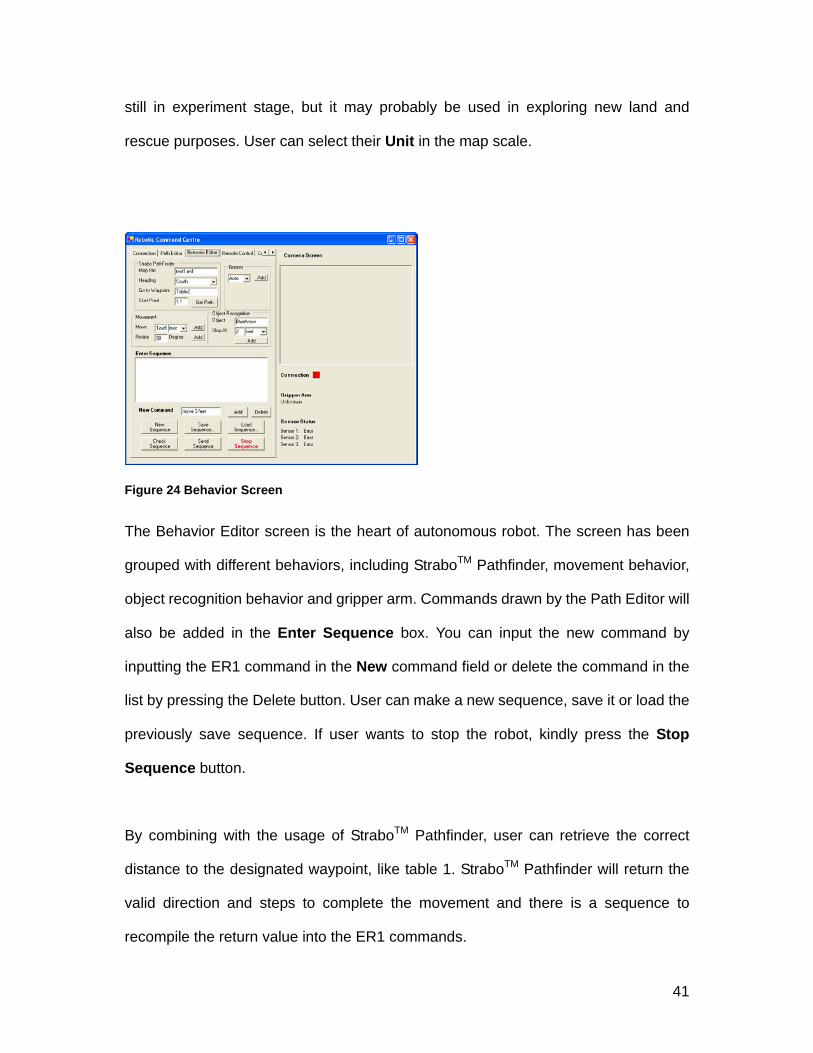
Figure 24 Behavior Screen
The Behavior Editor screen is the heart of autonomous robot. The screen has been
grouped with different behaviors, including StraboTM Pathfinder, movement behavior,
object recognition behavior and gripper arm. Commands drawn by the Path Editor will
also be added in the Enter Sequence box. You can input the new command by
inputting the ER1 command in the New command field or delete the command in the
list by pressing the Delete button. User can make a new sequence, save it or load the
previously save sequence. If user wants to stop the robot, kindly press the Stop
Sequence button.
By combining with the usage of StraboTM Pathfinder, user can retrieve the correct
distance to the designated waypoint, like table 1. StraboTM Pathfinder will return the
valid direction and steps to complete the movement and there is a sequence to
recompile the return value into the ER1 commands.

42
Figure 25 Remote Control Screen
User can also remote control the robot if they want. It includes direct movement of the
robot, wheel rotation setting, IR sensor setting and Gripper control, etc.
Figure 26 Camera Setting Screen
Camera resolution and capture setting can be formulated under the Camera tab
screen.

43
Figure 27 Notes Screen
Notes screen provide a basic command reminder for user to formulate different
behaviors.
Figure 28 About Screen
About this program screen.

44
V. ANALYSIS OF ALGORITHM / SYSTEM
We would like to develop a robot prototype for localization and path-finding using the
ER1 Robot as the framework. Given the reality that emerging technologies in
forthcoming year would include increasing use of speech recognition and generation,
new sensor technologies that allow users to touch, feel and smell objects in virtual
worlds, improved speech recognition and gesture recognition. We hope that our
studies on this subject matter will be inspired by the others to follow and enhance.
5.1 ER1 Robot Prototype We are able to fulfill the designated task with trial and error. Although the robot
prototype is improving every time, while we are developing the system we notice the
following shortcomings.
5.2 Limitations and Possible Solution 1. Python Software Development Kit lacks the capability to read low value IR
input, therefore, obstacle avoidance can not be enforced. In view of this, we
have shifted our development effort using Microsoft® Visual C# and Microsoft®
Visual Basic .NET.
2. Gripper arm do not have pressure senor, so if we use a cup made up of
soft-paper, the cup will be under high pressure and change it to oval-shape as
shown below. Tested with plastic cup and canned media do not pose any
problem.

45
Figure 29 Problem of Holding
Paper-made Coffee Cup
Figure 30 Rubber-made Coffee
Cup is the minimum
requirement of the holding
media
Figure 31 Canned Coffee do not
pose any problem with the ER1
Gripper
3. Image recognition will be affected by light and ambient effects. Whether the
light is not enough, the robot need to trace for its target, sometimes, a looping
problem will occur. In view of this, we have replaced the bundled Webcam with
a high quality Logitech® QuickCam® Pro 4000 which get satisfactory result.
4. The robot would not move if the laptop was being charged. Also, due to severe
consumption of power by wireless network, the original IBM ThinkPad X24
notebook computer cannot stand more than 1 hour, which is too cumbersome
for frequent charging, we have ordered a new IBM ThinkPad X40 notebook
computer which has built-in wireless LAN and can stand for more than 7 hours
according to the specification.
5. We notice that navigation for robot is an important element and future research
in the coming year because as our testing and some findings from different
sources, there is still quite a lot of enhancement. Because of this, StraboTM
Pathfinder has been purchased for easy manipulation of the robot navigation
behavior.

46
6. We do not have electronic compass to have accurate directional facility, when
using with StraboTM Pathfinder, we need to either put the robot to face absolute
north or east in our implementation.
5.3 Experimental Setup We broke the testing of our robot into two categories. They are the basic functionality
and usability. The basic functionality goals were to have the ER1 Robot able to
perform basic actions from our user interface. These three basic actions were to
establish a connection, backwards and forwards movement, rotation, and gripper arm
control. All of these are essential for any development of the Robotic Command
Centre to continue.
Our usability goals were the set of goals for which controlling the robot would be
simpler and easier for the robot controller. It would be time-consuming for the user to
have to release ever command after he decided what he wanted to do. Instead, we
created a command queue, which is a list of user commands that the robot user
would like to send and it is also essential for localization through StraboTM Pathfinder.
Due to the limited space in my home, the experiments are conducted on a narrow
straight corridor in an office-like indoor environment with a relatively dimmed lighting
condition. The corridor extends about 7 feet in length and 6 feet in width. In a narrow
opening like a corridor, the robot moves with a speed slower than an average walking
speed. The movement behavior and object recognition behavior are the essential
elements that must be executed during the experiment navigation. The collision

47
detection by the three IR sensors is executed in another thread.
Figure 32 Partial Enviroment Setup
The most important mission of the experiments is to analyze and verify the
performance of the control system as well as to accomplish a successful navigation.
Therefore, the robot is evaluated in each of the criteria listed as the following.
1. Mechanisms (targets: Collision Detection and Object Recognition) a. Robot with collision detection b. Full feature (collision detection and object recognition)
2. Robot control system a. Modularity and usability b. Safety (system safety and robustness)
For the purpose of evaluating the performance with respect to safety, on each experiment the robot runs in a corridor with obstacles as in Figure 32. Because of the dead-end in the corridor, an extra control subroutine is added to the movement behavior in which the robot will slow down its speed or stop entirely to avoid collision with the wall. Object Recognition with direction sign for homing (Figure 32) has also been tested to see how the robot tackles to these problems.

48
Figure 33 Partial Environment Setup - StraboTM
5.4 Experimental Results As a result, the robot has shown both desired and problematic behaviors. In the
matter of collision detection, the robot is able to avoid collisions with obstacles and
walls. The collision detection mechanism maneuvered the vehicle around and
navigated it to the end of the hallway without collisions. There were also some
problems, however. First of all, the behavior was often distracted by ambient light,
which caused the retardation in navigating the robot. As a possible solution, we have
lowered all the sensor range to 1.5 feet to improve sensor readings for applying
collision detection. However, oftentimes it will require a sensor calibration in each and
every unique environment.

49
The path generated by StraboTM Pathfinder do not make into the consideration of
coarse floor plan. As a result, most of the time, there is minor deviation though they
are not pose serious problem in terms of safety in navigation. Although an
improvement still needs to be made with respect to the accuracy in selecting the valid
path for target destination, the main problem is the way to handle the unknown terrain
outside a normal workspace. In principle, the robotic command system has no central
brain in the system, and any information posted on the robotic command centre must
be handled and interpreted by respective devices. In the current system, the
movement behavior is the only device dealing with the shared information that
reflects on the robot’s actuators.
The images obtained by the system camera show that the mechanism identifies the
object almost perfectly. However, the ratio of correctness drops in identifying the
object with increasing distance. In fact, it is extremely difficult to always make correct
judgments in the dynamic scene without giving an appropriate amount of hints. It is
the simplest solution with one drawback; that is, adding more parameters may
deprive the robot of the adaptability to environments. There may be more solutions.
For instance, we have increased the image capture resolution from 640 x 480 RGB
Color and get desired result.
There were some interesting behaviors exhibited by the robot. The robot was
originally designed to do only three things: avoid collisions, travel destination and
recognize object for homing. However, the robot also demonstrated unexpected
movements: obstacle avoidance and smart homing. Originally, I would like to
re-create the reverse direction for robot homing, due to some deviations in robot
movement, homing may not be too accurate due to increased deviations from false

50
calculation by wheel in a uneven floor. We use two pictures for guidance and
re-position of the robot and it found to be quite successful in homing for several times.
Further testing found that with the new Logitech® QuickCam® Pro 4000, the robot can
recognize an object over 25 feet (it is the maximum length of my home) with improved
image quality and faster transfer speed for RCC’s object recognition.
Figure 34 “Right Arrow” Sign for Homing
Figure 35 "Home" Sign for Homing
As mentioned in the previous chapters, the objective of this experiment was to design
and build a robot control program that is easy to use and easy to expand (modify) for
future study. To begin with, the control system succeeded in facilitating modularity and
usability. The complete modulation in the class hierarchy brought forth an effortless
implementation, and the intelligible user interface has navigational parameters all
adjustable and realizes the smooth experiment processes. The GUI (Graphical User
Interface) written in Microsoft® Visual Studio .NET is shown in Section 4.7.7.
Besides localization and path-finding abilities of the robot, with the combination effort
of Remote Control and Path Editor, we can design a pre-programmed behavior for

51
robot movement and other action. It is particularly useful for danger zone or new land
exploration (e.g. in the Mars or other planets).
Figure 36 ER1 Robot with Torch Light in the Dark
Figure 37 Capture Image of Front vVew from
ER1 with Torch Light
5.3 Discussion The collision avoidance behavior, object recognition behavior, navigational behavior,
and the system responsible for hardware components all cooperate within the robotic
control system. The robot and the control system were presented and analyzed in the
experiments. As a result, the robot did not exhibit the perfectly desired performance,
but the layered approach in the design criteria has proved its feasibility in mobile
robot navigation. The problems faced during the experiments are more related to the
calibration against an environment and the parameter adjustment on the agents than
the fundamental design criteria of the control system. The proposed layered
architecture enabled the control system to be easily expandable, and the use of
user-friendly GUI and user-modifiable StraboTM Pathfinder map has made the system
more easily cope with different user-requirement for them.
Although there is some deviation of the target position due to uneven environment,

52
remedy method by using the attached camera to re-position the robot using
sign-board method has proven successfully for homing. With the implementation of
collision mechanism, the robot demonstrated safe navigation in a hallway using a set
of IR proximity sensors.
As the current ongoing research, possible solutions are being implemented to
compensate for this problem. For example, Evolution NorthStar technology that
addresses this long-standing problem. It uses a small, inexpensive sensor (usually
placed inside the commercial robot) and an infrared, encrypted light device that plugs
into a wall outlet to help a robot not only navigate from room to room, but actually
know which room it's in.
Figure 38 NorthStar Detector (Left) & NorthStar IR Projector (Right)
The NorthStar detector uses triangulation to measure a product’s exact position and
heading in relation to IR light spots projected onto the ceiling (or any visible surface).
Because each IR light spot has a unique signature, the detector can instantly and
unambiguously determine where the product is. Because the NorthStar detector
directly measures a product’s position and heading, the localization result is
intrinsically robust. A NorthStar-enabled product does not require prior training or
mapping to measure its position. There is no need for expensive computational

53
capabilities. The system is insensitive to changes in the environment such as moving
furniture or people and works in complete darkness.
Figure 39 NorthStar in Operation
So we can build our indoor GPS-like Robot which is similar to the robot using GPS
facility outdoor. However, it is only available in the first quarter of 2005.
Further study is sought to design an agent which actually performs the
landmark-based navigation extending machine vision techniques in collaboration with
NorthStar technology. It is foreseeable that using a robot to navigate different areas in
the home and return image or doing some other stuff with accurate position can be
achieved in the not long distant future. The price of the hardware and software for
NorthStar is 1,495 US dollars.

54
VI. CONCLUSIONS
Upon the studying of different technologies in behavior-based robotic system, we
have a better understanding of the overall design strategy of future robotic design.
There is always a trade-off between AI implementation and rule-based
implementation. To the former, it is more easier to adapt to different environment, but
the speed of adequate learning is a great concern. To the later, it often produces
favorite result and greater control to the programmer or end user. By analyzing both
Lego® MindstormsTM and Evolution Robotics ER1 Robot, we have a more clearer
picture in implementation details. With the experiment to build a robot prototype, we
found several incapability of using merely its Robot Control Centre as a sole mean to
implement all the robot behaviors because of its limitations. There is a need to use
either socket API or Evolution Robotic Software Platform (ERSP) to further elaborate
the behavior. However, the price maybe out of our preliminary budget (USD7,500 for
ERSP), therefore, we have tried using Python to elaborate some of the robotic
behavior, however, producing simply move, recognize, grab functions, etc are simple
but it really takes quite a lot of time to make it completes which maybe better to find
another tool. Therefore, we shift to Microsoft® Visual Studio .NET which proves to be
more valuable to complete the requirement. Finally, we developed the ER1 Robot
Prototype with localization and path-finding abilities using Evolution Robotics’ ER1
Robot as the framework. We believe that building software is not easy, but software
engineering is the key to dealing with the difficulties. With good software engineering,
we solve our problem in a systematic and justifiable manner.

55
VII. REFERENCES
Simon H., "Neural Networks", 1994 Macmillan College Publishing Company Inc
Sullivan B., 2002, http://www.msnbc.com/news/817145.asp?0dm=C11KT, Accessed
2003 Mar 10
New Robot controller Is Customer Programmable with Microsoft .NET Compact
Framework, Microsoft Corporation, 2003
An Indoor GPS Robot, PC Magazine, Lance Ulanoff, 25 October 2004/12/7
LARS – Laser-guided Autonomous Robotic System, Jacob Creed & Brandt Erickson,
2003
View-based vs. place-based navigation: What is recognized in recognition-triggered
responses?, Hanspeter A. Mallot & Sabine Gillner, October 1998
Achieving Artificial Intelligence Through Building Robots, Rodney A. Brooks, May
1986
On Three-Layer Architectures, Erann Gat, California Institute of Technology
Teaching Robot Localization with the Evolution ER1, Zachary Dodds, Steven
Santana, Brandt Erickson, Kamil Wnuk, Jessica Fisher, Matt Livianu, Havey Mudd
56
College, 2003
Arras, K.O. and Tomatis, N. (1999) Improving robustness and precision in mobile
robot localization by using laser range finding and monocular vision. Proceedings of
the Third European Workshop on Advanced Mobile Robots, Eurobot’99, Zurich,
Switzerland.
http://citeseer.nj.nec.com/arras01multisensor.html
Arras, K. O., Tomatis, N. and Siegwart, R. (2000) Multisensor on-the-fly localization
using laser and vision. Proceedings of the 2000 IEEE/RSJ International Conference
on Intelligent Robots and Systems, Takamatsu, Japan, 793-8.
Benet, G. and et al. (2002) Using infrared sensors for distance measurement in
mobile robots. Robotics and Autonomous Systems 40: 255-66.
Bertozzi, M., Broggi, A. and Fascioli, A. (2000) Vision-based intelligent vehicles: state
of the art and perspectives. Robotics and Autonomous Systems 32: 1-16.
Borenstein, J. and Koren, Y. (1988) Obstacle avoidance with ultrasonic sensors.
IEEE Journal of Robotics and Automation RA-4(2): 213-8.
Borenstein, J. and Koren, Y. (1991) The Vector Field Histogram -- Fast
obstacle-avoidance for mobile robots. IEEE Journal of Robotics and Automation 7(3):
278-88.
Brooks, R. A. (1986) A robust layered control system for a Mobile Robot. IEEE

57
Journal of Robotics and Automation, RA-2(1): 14-23.
Brooks, R. A. (1991) Intelligent without representation. Artificial Intelligence 47:
139-59.
Corkill, D. D. (1991) Blackboard systems. AI Expert 6(9): 40-7.
Corkill, D. D. (2003) Collaborating software: blackboard and multi-agent systems &
the future. Proceedings of the International Lisp Conference 2003, New York, NY.
http://dancorkill.home.comcast.net/pubs/ilc03.pdf
Jensfelt, P. (2001) Approaches to mobile robot localization in indoor environments.
Ph.D. dissertation, Department of Signals, Sensors and Systems, Royal Institute of
Technology, Stockholm, Sweden.
Kube, C. R. (1996) A minimal infrared obstacle detection scheme. The Robotics
Practitioner: The Journal for Robot Builders 2(2): 15-20.
Liscano, R. and et al. (1995) Using a blackboard to integrate multiple activities and
achieve strategic reasoning for mobile-robot navigation. IEEE Expert 10(2): 24-36.
Maaref, H. and Barret, C. (2002) Sensor-based navigation of a mobile robot in an
indoor environment. Robotics and Autonomous Systems 38: 1-18.
Martinez, A., Tunstel, E. and Jamshidi M. (1994) Fuzzy logic based collision
avoidance for a mobile robot. Robotica (12): 521-7.

58
Mataric´, M. J. (1992) Behavior-based control: main properties and implications.
Proceedings of the IEEE International Conference on Robotics and Automation,
Workshop on Architectures for Intelligent Control Systems, Nice, France, 46-54.
Matsumoto Y. and et al. (1999) Exploration and map acquisition for view-based
navigation in corridor environment. Proceedings of the International Conference on
Field and Service Robotics, Pittsburgh, PA, 341-6.
Saffiotti, A. (1997) The uses of fuzzy logic in autonomous robot navigation. Soft
Computing 1(4): 180-97.
Sierra, C., L´opez de M`antaras, R. and Busquets, D. (2001) Multiagent bidding
mechanisms for robot qualitative navigation. Proceedings of the Seventh International
Workshop on Agent Theories, Architectures, and Languages (ATAL-2000), Boston,
MA, 198-212.
Tunstel, E. and Jamshidi, M. (1994) Embedded fuzzy logic-based wall-following
behavior for mobile robot navigation. Proceedings of the First International Joint
Conference of the North American Fuzzy Information Processing Society Biannual
Conference, San Antonio, TX, 329-30.
Ushimi, N. and et al. (2002) Online navigation of mobile robot among moving
obstacles using ultrasonic sensors. In Birk, A., Coradeschi, S., and Tadokoro, S., eds.,
RoboCup 2001: robot soccer world cup V ,LNAI-2377, 477-83. Berlin:
Springer-Verlag.

59
APPENDICES
Appendix A –Project Planning – key dates

60
Appendix B – Robotic Command Centre API Standard Robot Commands Quick Reference exit gripper auto gripper close gripper open gripper status gripper stop IR move move rotate toward object move rotate toward color move drive toward object move drive toward color play file play phrase stop sense sense gripper clear
events sense IR set IR set voice set linear velocity set angular velocity set power stopped set power moving set collision detection off set collision detection on set obstacle avoidance off set obstacle avoidance on set confidence threshold set color tolerance set color percentage input digital output digital input analog