how to build - arcadecontrols.comarcadecontrols.com/files/miscellaneous/spinner.pdf · how to build...
TRANSCRIPT

How to build
What is the Cheep Spinner?
The Cheep Spinner is my solution to the question: “Just how am I supposed toplay Tempest* without real arcade controls?” (*or any other games using spinners)
After looking into the different options - from buying a real arcade spinner to thevarious online build-it-yourself plans - I decided to design and build my ownspinner control.
The project had several goals: 1) it had to work well 2) it had to be relatively easyto build 3) it had to be sturdy 4) it had to be made out of commonly availableparts, and 5) it had to be dirt cheap. Good dirt, but dirt nonetheless.
Anyway, this PDF guide goes through the process step-by-step. It may not be theeasiest spinner to build, but it’s certainly one of the cheapest, and it works great!I hope you get as much satisfaction out of building one as I did.
The plans for the Cheep Spinner are available exclusively from Cheep Technology.You are welcome to download and print out these instructions for your own use,but please contact me if you wish to post these plans on a website.
Thank you, and enjoy using your Cheep Spinner - the only build-it-yourself spinnerproject with a little chicken for a mascot.
Nathan [email protected]
http://www.cheeptech.com/
“Cheep Technology”, “Cheep Spinner”, “Cheep” and all materials in this PDF document are © 2000 Nathan StrumGames and products listed are copyrighted by the companies that own them

How to build
Table of contents
1 IntroductionThe story behind the Cheep Spinner.
2 Table of contentsThis page. Where to find stuff.
3 How the thing worksMore than you probably want to know about mice.
4 Frequently asked questionsThe only stupid questions are those that go unasked... those and “got any romz dood?”
5 Tools you’ll needHopefully you’ll have most of this stuff around already.
7 Parts listA few bucks and a trip to the hardware store and Radio Shack will set you up.
9 Building the spinnerHow to put together the part that spins - the knob and bearing assembly.
13 Making an encoder wheelWhy make one? Because it works better than the mouse’s. A lot better.
17 Mouse brain surgeryA new encoder wheel means you have to relocate some mouse parts.
24 Finishing it offPutting it all together.
27 Appendix A - Adding a counterweightOptional steps for giving it that real arcade “feel”.
28 Appendix B - Relubricating the spinnerHow to make it work like new, again and again.
29 Appendix C - Game settingsSuggested settings for some MacMAME games that make good use of the spinner.
34 Appendix D - Encoder wheelsPrintable encoder wheels for use with this project.
35 Appendix E - Making an encoder wheel: the hard wayUse this method if you don’t own a Dremel. It works, but it’s time-consuming.
39 Appendix F - Control panel mountingSuper-easy instructions on how to mount the Cheep Spinner in a control panel.
42 Appendix G - Adding arcade fire buttonsHooking up real arcade fire buttons to the Cheep Spinner.
47 Appendix H - Variations on a themeThe original prototype, plus a version that’s ADB and USB all in one.
2
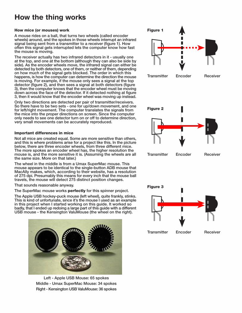
How mice (or mouses) workA mouse rides on a ball, that turns two wheels (called encoderwheels) around, and the spokes in those wheels interrupt an infraredsignal being sent from a transmitter to a receiver (figure 1). Howoften this signal gets interrupted lets the computer know how fastthe mouse is moving.The receiver actually has two infrared detectors in it - usually oneat the top, and one at the bottom (although they can also be side byside). As the encoder wheels move, the infrared signal can either bedetected by both detectors, one of them, or neither of them, dependingon how much of the signal gets blocked. The order in which thishappens, is how the computer can determine the direction the mouseis moving. For example, if the mouse only sees a signal at the topdetector (figure 2), and then sees a signal at both detectors (figure3), then the computer knows that the encoder wheel must be movingdown across the face of the detector. If it detected nothing at figure3, then it would know that the encoder wheel was moving up instead.Only two directions are detected per pair of transmitter/receivers.So there have to be two sets - one for up/down movement, and onefor left/right movement. The computer translates the signals fromthe mice into the proper directions on screen. Since the computeronly needs to see one detector turn on or off to determine direction,very small movements can be accurately reproduced.
Important differences in miceNot all mice are created equal. Some are more sensitive than others,and this is where problems arise for a project like this. In the picturebelow, there are three encoder wheels, from three different mice.The more spokes an encoder wheel has, the higher resolution themouse is, and the more sensitive it is. (Assuming the wheels are allthe same size. More on that later.)The wheel in the middle is from a Umax SuperMac mouse. Thismouse appears to be identical to the single-button ADB mouse thatMacAlly makes, which, according to their website, has a resolutionof 275 dpi. Presumably this means for every inch that the mouse balltravels, the mouse will detect 275 distinct position changes.That sounds reasonable anyway.The SuperMac mouse works perfectly for this spinner project.The Apple USB hockey-puck mouse (left wheel), quite frankly, stinks.This is kind of unfortunate, since it’s the mouse I used as an examplein this project when I started working on this guide. It worked sobadly, that I ended up redoing a large part of this guide with a differentUSB mouse - the Kensington ValuMouse (the wheel on the right).
How the thing works
Left - Apple USB Mouse: 65 spokesMiddle - Umax SuperMac Mouse: 34 spokesRight - Kensington USB ValuMouse: 36 spokes
3
Transmitter Encoder Receiver
Figure 1
Transmitter Encoder Receiver
Figure 2
Transmitter Encoder Receiver
Figure 3

Left - Kensington USB 3 Button ValuMouseRight - Umax SuperMac Mouse
The Kensington mouse worked very well for this project. The reason is resolution. The Kensington mouse is muchlower resolution than the Apple USB mouse, and therefore less sensitive. A higher resolution mouse is designed totravel a shorter distance for the signal to be interrupted, and more signals get sent for every inch of movement.Conversely, the fewer spokes there are, the farther the ends of the spokes must travel in order to interrupt the infraredsignal. This is how you can tell mice apart, short of knowing their specifications. Additionally, a larger encoder wheelalso reduces the sensitivity of a mouse, since that will also increase the distance between the ends of the spokes.
Why does this make any difference?A mouse designed to be moved very short distances doesn’t handle a high rate of speed well. It’s designed to bemoved very little to generate a response. If an encoder wheel is moving too fast, more data gets sent through themouse than it can handle. The end result is that when the spinner is spun extremely fast, not every signal gets throughto the computer, and the cursor will hover in place or even move backwards . The effect is similar to the “strobing”you see on television when car wheels appear to be moving backwards. You generally can’t get a mouse to move thatfast across a desk, but spinners often hit those speeds. Having the cursor “freak out” like this is hardly acceptable ingaming, so starting out with the right mouse is probably the most important consideration when doing this project.Since this problem is associated with the design of the mouse itself, software adjustments can’t help much. Somesoftware (like Kensington’s MouseWorks) actually make the problem worse, by increasing the mouse’s sensitivity.Low resolution mice seem a lot less prone to this problem than the high resolution ones. This may also have somethingto do with how close the decectors are to each other, since in a high resolution mouse, they must be closer togetherin order to properly read the much narrower and closer together spokes. Therefore, the receiver may be a lot pickierabout being aligned exactly perpendicular to the spokes, or misreads could occur.
How the thing works (continued)
4
So, what mouse do you get?If you have an ADB Mac, you can either scrounge up a used Mac clonemouse (most seem to be the same type), or fork over $16 - $30 for aMacAlly one. The SuperMac mouse (on the right) works great in theCheep Spinner and is the one I used before I got USB in my Mac.If you need a USB spinner, then the Kensington USB 3 Button ValuMouseis the clear winner. It costs only $12.99, works great in the spinner andis really easy to desolder too (which is a big plus).Avoid Apple’s USB hockey-puck mouse. It’s really terrible. It’s too badthough, since there are more of these things taking up landfill spacethan Atari 2600 “E.T.” cartridges, and it’d be nice to find a use for them.If you’re a PC user, I’m afraid you’re on your own. Since I don’t have aPC, I can’t tell you how well the USB spinner works on it, nor how wellthe serial or PS/2 versions of the Kensington ValuMouse would work.I don’t want to make a recommendation on something unless I’ve hadthe chance to personally test it out. Sorry.
Frequently asked questions
Believe it or not, I’m already getting a lot of questions regarding this project, and that’s just from an early version ofthis guide that I posted up. Must be a lot of Tempest junkies out there.
Q. Are you going to build these and sell them?A. Only on a very limited basis. I’ll probably limit the orders to four per month, just to be manageable.
Q. Have you considered using Happ (or other) optical parts, instead of a mouse?A. One of the goals for this project, was to build it using no commercial arcade parts. I wanted to be able to pickeverything up at local stores. However, I will be testing out some parts from Happ, to see how well they work with thebasic Cheep Spinner design. If it’s successful, I’ll create a separate guide detailing that project. Keep in mind though,that it will cost considerably more to build than this one does. At least double. The benefit would be easier construction.
Q. Can you hook up a steering wheel to it?A. I haven’t tried it, but I would assume you could just screw a Frisbee onto the knob for a Cheep Steering Wheel.
Q. What about Discs of Tron? Can you make a multi-position spinner like that one?A. You never know...

Tools you’ll need
1. You will need a soldering iron. You need one with a small tip, around15 - 30 watts, so you won’t overcook anything. Don’t use one of those bigsoldering guns, they’ll just melt everything. Radio Shack sells a bunch ofdifferent ones - if you don’t plan on doing much of this type of work, prettymuch any cheap one will do. If you’re going to be doing a lot of soldering,it’s worth investing in a good one. I use a Hakko 907 with a variabletemperature control. Weller also makes good soldering irons.2. You need either a desoldering iron ($10 at Radio Shack) or desolderingbulb or vacuum tool. If you plan on doing very many projects of this sortit’s worth buying a desoldering iron.
8. Hammer (for using the centerpunch, and flattening outunruly pieces of metal)9. Marking pen (fine point - must write on metal)10. Centerpunch11. Drill bits: 3/32”, 9/64”, 5/32”, 1/4”12. 3/4” hole saw (must be able to cut through metal) - thiswill cost about $20 ($13.50 for the mandrel, $7 for the saw).However, you can reuse the mandrel with other size holesaws, which you’ll need if you ever build any projects witharcade buttons.13. Adjustable wrench (4” or 6”) $6.63 for a 4” wrench14. Narrow needlenose pliers15. Scratch awl (or just file down an old screwdriver)16. Phillips screwdriver17. Flat screwdriver
18. Drill. Preferably a variable speed, reversiblemodel. You’ll be drilling through plastic, steel, brassand brittle circuit board material. It will also need tohave a chuck large enough for the hole saw.
19. Vice. I picked this one up for $10.63 at HomeDepot. You’ll need this for holding metal while drillingthrough it. It’s much safer than trying to steady itwith your hands.
3. You’ll need some rosin-core solder. Get some that says for it’s forfine electronic soldering or circuit boards (63% lead/37% tin). $2.994. Tweezers. Either small spring-loaded tweezers or a clip-on heat sink,to clamp wires in place while soldering. Locking forceps should also work.5. Some electrical tape is also needed for this project. Again, you won’tneed much.6. Wire cutters. A good set of flush-cutting wire cutters (aka nippers).$3.99 at Radio Shack.7. Wire stripper. Nothing fancy. $2.99 at Radio Shack
5 6
8
13 14 15
16
17
9
19
1
2
18
5
7
3
4
10 11 12

Tools you’ll need (continued)
26. Thread locking fluid. Comes under brands like Loc-Tite, Tite’N, andprobably some other ones that are misspelled. $3.4727. WD-40. Like Tabasco sauce and Q-Tips, I think everyone has someof this stuff in their home. Here, it’s used to degrease the bearings. Makesa cool flame-thrower too. (Don’t try this at home, kids.) $2.98 (2 pack)28. Silicone spray lubricant. After cleaning the bearings off, I use thisto re-lube them. You can use WD-40 too, but this stuff seems to do abetter job. Seems smoother. $2.9729. Flat black spray paint. For painting the encoder wheel. $3.4930. 3M Super 77 spray adhesive. You need this to glue the paperpattern onto the plastic encoder wheel. You can use different glue, aslong as it won’t wrinkle the paper, or come loose. $7.99 for a large can,or less if you can find a small one as shown.
20. Files. You should have a flat file, and a small round one.Used for cleaning the rough edges off cuts and holes.21. Single edged razor blade. Don’t use a double-edged one,since you can’t grip them safely, and they’re too flexible.22. Utility knife. Make sure you have a fresh blade installed.This and the razor blade will be used for making the encoderwheel (if using a Dremel, you won’t need this).23. Razor saw. X-acto makes this, and it sells for about $10.It’s extremely sharp, so be careful with it - it cuts through thumbsvery well. Use this for cutting the circuit board and plasticencoder wheel. You could probably also use a hacksaw with avery fine blade.24. Tin snips. For cutting the brass and plastic. You could alsouse a hacksaw with a very fine blade.25. Fine grit sandpaper. Used for cleaning off rough edges.320 grit (or similar) should work.
A few notes on the projectMost of the parts were bought at Home Depot. The nylon spacers, rubber feet and brass strip were bought at a Do-ItCenter, but other hardware stores should carry that stuff, too. The Kensington USB mouse was bought at Circuit City.This project assumes you know how to use a drill, a soldering iron, desoldering techniques, and a few other tools. Ifnot, check out a community college. Most should offer some sort of basic classes. I think Radio Shack also sells abook on how to solder.You’ll need a table or desk to work on, including somewhere to clamp the vise down. Since this project involves drillingand cutting various materials, you might want to put some newspaper down if you’re inside, so you don’t end up withstuff imbedded in your carpet. Good lighting is really important, as is ventilation when soldering or using chemicals.It’s also not a bad idea to use a dust mask if you use a Dremel, since it has a tendency to kick debris everywhere.Speaking of safety, be sure to read, understand, and follow all of the safety rules that come with your power tools.Knowing how to use your power tools properly will greatly reduce the risk of personal injury lawsuits.And remember, there’s no more important safety rule than to wear these safety glasses.Personally, I would’ve thought “don’t stick your hand in the table saw while it’s running” would’ve been at least equallyimportant, but I guess Norm knows what he’s talking about.
RecommendedI strongly recommend buying a Dremel (or similar) motorized tool.This will save you a lot of time cutting and sanding. You can pickup a starter kit for around $40 (avoid the rechargeable ones). Thereinforced cutting discs alone are worth having one - so makesure you buy some if they aren’t included. $6.97 (five pack). Ialso used a high speed cutter (#199) for the encoder wheel. $5.99
20
21 22
23
2524
2627 28 29
6
30

Parts list
1. Mouse. Either USB (left) or ADB (right). The procedure is basicallythe same for either one. Make sure the left/right direction works on it- the rest of it can be broken. Be sure to read “How the thing works”at the beginning of this PDF file. Some mice work better than othersfor this project. The Kensington 3 button USB ValuMouse (far left)is the recommended choice for a USB mouse. $12.992. Wire. I used some leftover category 5 (ethernet) wire. It has enoughdifferent colors to keep track of the connections, plus it’s stiff, so whenyou bend it out of the way, it stays out of the way. Also, it’s smallenough to fit into the holes on the circuit board. If you don’t have anyscrap around, you can buy the shortest pre-made cable you can find,and snip off the ends. Any small diameter wire will do, however.
To the hardware store!3. 3 9/16” round blank electrical box cover. Look in theelectrical section. If you can’t find this, they have octagonal oneswhich should also work. Try to get one that’s solid (no knockouthole in the center). This is the optional counterweight. 74¢4. 1 7/8” rubber caster. The knob. There’s usually a series ofbins with various casters in them. Get the solid one, not the cheapplastic one (but don’t waste your money on the swivel type, unlessyou have to. $2.685. Patio Door Roller. Be sure to get metal, not nylon. This isthe bearing that makes the whole thing work. It comes packedwith heavy grease you’ll have to clean out of it, but then it’ll spinperfectly. Look in the door hardware section. $4.97 (two perpackage)6. 5” x 3 1/8” steel tie plates. Look in the construction section.These are used to tie rafters, beams, etc., together. This will bethe main housing for the spinner parts. You need 2 at 32¢ each.Buy a couple extra for practice.7. .025” x 1” x 1 ft. brass strip. Any metal will do, but this iseasy to work with. This is to make a bracket to hold the opticalsender and receiver. $1.19
8. 1/4” machine screw, 3” long. The shaft. 78¢ (bag of 3 -includes 3 nuts)9. 1/4” coarse thread nuts. You need 3 for the shaft. Includedwith machine screws from item #8.10. 1/4” coarse thread jam nuts. Similar to item #9, but lowerprofile. You need four if you’re adding the counterweight, or two ifyou aren’t. 78¢ (bag of 6)11. Nylon spacers - 3/4” long x 1/4” outer diameter (must bebig enough for a #6-32 machine screw to fit into it). 4 at 12¢ each.12. #6-32 machine screws, 1” long. You need four screws, pluseight #6 nuts and four #6 washers. 78¢ (bag of 4 screws - includes4 nuts), 78¢ (bag of 12 nuts), 78¢ (bag of 30 washers).13-15. #6-32 machine screws, 1/2” long. You need 8 screws, 20nuts, and two washers. 78¢ (bag of 8 screws - includes 8 nuts),78¢ (bag of 12 nuts), use leftover nuts and washers from item #12.16. 1/4” machine screw, 1” long. This is used during assemblya couple of times. 78¢ (bag of 4 - includes 4 nuts)
8
9 10
11
13 1614 15
12
34
7
5 6
Hint: If you separate the parts like this,it’ll make sense later on.
7
12

Parts list (continued)
On to Radio Shack20. Printed circuit board. Be sure it’s the type where theholes are separate from each other. Radio Shack part #276-148A. It says it can be “snapped in half”. Don’t you believeit. Cut that sucker instead. $1.4921. Project box. The one I used for this is 6” x 4” x 2”(Radio Shack part #270-1806). $4.39 This is the absolutesmallest box that can be used for this project, as describedin this guide. I used a 7” x 5” x 3” box for the originalprototype, which worked fine, and left more of a margin forerror (Radio Shack part #270-1807). $5.89
Optionally, instead of a project box, you can adapt thisdesign to work underneath a control panel. Please seeAppendix F for details. However, you’ll still need thealuminum lid that comes with the project box (or just a flat3 7/8” x 5 7/8” piece of aluminum) to use as a mountingplate.
17. 1/4” washers. Used to protect the encoder wheel. 78¢ (bag of 12)18. 3” ABS DWV test cap. You’ll find these in the plumbing section, whereall of the black ABS plastic pipe is. This will become the encoder wheel.You might want to buy a few, just to have spares. 65¢
22. Tunes. Whatever floats your boat. Journey’s Greatest Hits worksparticularly well for an arcade-related project. (They did have their ownvideo game, after all.) $13.99
Total parts cost*:$38.47*(Includes ValuMouse. Does not include tools, wire, or Steve Perry.)
So now that you’re all done shopping, let’s get ready to work and makesome arcade magic!
21
19. Rubber feet. Any will do. I picked up four gray 3/4” x 15/16” rubberbumpers that have a screw through the center to hold them on. $1.23
Optional partsYou can use any knob that can be secured to a 1/4” shaft. Just buy a pieceof 1/4” threaded rod instead of item #8, and cut it to length.If you can’t find the spacers shown in #11, you can use four stacks of six #6washers instead (24 washers total). You’ll probably want to glue themtogether, so they’re easier to put in place. 78¢ (bag of 30)For the encoder wheel, any 3” sturdy plastic disc will do. I used the ABS capso you’ll know there’s something specific that will work.
17
18
19
20
22
8
Building the spinner
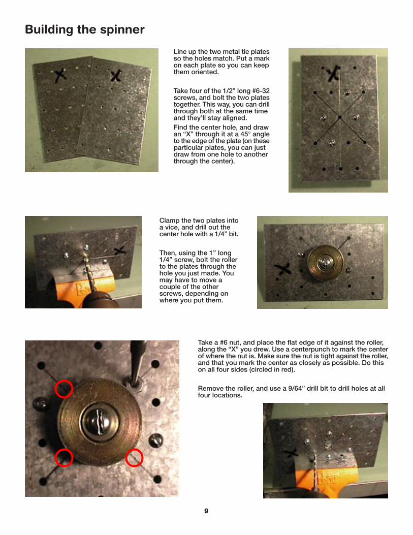
Line up the two metal tie platesso the holes match. Put a markon each plate so you can keepthem oriented.
Take four of the 1/2” long #6-32screws, and bolt the two platestogether. This way, you can drillthrough both at the same timeand they’ll stay aligned.Find the center hole, and drawan “X” through it at a 45° angleto the edge of the plate (on theseparticular plates, you can justdraw from one hole to anotherthrough the center).
Clamp the two plates intoa vice, and drill out thecenter hole with a 1/4” bit.
Then, using the 1” long1/4” screw, bolt the rollerto the plates through thehole you just made. Youmay have to move acouple of the otherscrews, depending onwhere you put them.
Take a #6 nut, and place the flat edge of it against the roller,along the “X” you drew. Use a centerpunch to mark the centerof where the nut is. Make sure the nut is tight against the roller,and that you mark the center as closely as possible. Do thison all four sides (circled in red).
Remove the roller, and use a 9/64” drill bit to drill holes at allfour locations.
9

Building the spinner (continued)
Reinstall the roller asbefore. Then attacha #6-32 screw andnut through each ofthe holes you justdrilled, with the flatpart of the nutagainst the roller.These should besnug, and as youtighten the screws,the nuts should lockagainst the roller.If it’s too tight,slightly ream outone of the smallholes, and try againuntil all four fit.
Remove the rolleragain. Use the 3/4” holesaw to drill out thecenter hole. Let the sawdo the work - don’tforce it into the metal.
Once that’s done,unbolt the plates, andfile down any roughedges.
Note: If mounting the Cheep Spinner in a control panel,skip ahead to Appendix F. Otherwise, continue here.
Line up one of the plates onto the lid of your project box.If you’re using the small project box listed in the Partssection, be sure this is as close to being centered aspossible - there’s almost no room to spare inside.
10
Use the 9/64” bit to drill holes at all four cornersof the plates (use the holes in the plates as aguide). As you drill each hole, put a #6-32 screwthrough it to keep the plate from moving around.

Building the spinner (continued)
With the plate bolted to the lid (or control panel), use a scratchawl to mark the center hole. You can use the “X” marked on theplates as a guide to mark the center of the hole.
Use the 3/4” hole saw to drill out the center hole. You can leavethe plate attached as a guide if you want. Again, let the drill cutthrough the plastic at it’s own speed. You may want to cushionthe lid if you put it in a vise to hold it so it doesn’t get scratched.
Unscrew the plate from the lid, and set the lid aside.
Take the roller, and blast WD-40 into the channel where the ball bearings are. Theidea here is to remove all of the heavy grease that’s packed in there. This may takea bit of time to do. Periodically wipe away the grease with paper towel as you work,and spray from both sides. You’ll know you’re finished when the bearing spins freely.I put the roller into a plastic bag to do this, so I didn’t get WD-40 everywhere.Once it’s degreased, wipe it off really good, and lubricate it with the silicone spray(WD-40 should work, if you don’t have the silicone). Wipe off the excess.
Take the 1/2” long #6-32 screws, and put them through one ofthe plates where you drilled the four small holes. Attach eachof them with three nuts stacked one on top of another. Tighteneach nut down as you go.
11
This part is a little tricky.You have to place the roller back in the middle of the stacks, andwork it all the way back down to the plate. You will have to turnsome of the stacks as you go in order to line up their flat sides withthe roller and to get it to fit. It may take a bit of fussing, and you’llprobably have to “snap” the roller into place a few times.Once it’s all the way down against the plate, make sure the screwsare all tight. The roller shouldn’t move any side to side, but thebearing in the center should spin freely.The stacks of nuts should be the same height as (or slightly shorterthan) the roller. That way, when you bolt the other plate on, theroller will be pinched between them and won’t move .

Building the spinner (continued)
Put the other plate over the endsof the screws and squeeze thewhole thing together. Put somethread locking fluid on thescrews, and then tighten a nutdown on each one.The screw should just be evenwith the top of the nut, or slightlybelow it (you can also use longerscrews, then cut the ends off).
Take the caster apart.If it doesn’t have aremovable nut, you mayhave to cut off one endof the axle. Tosseverything except thewheel.Put the 3” long 1/4” boltthrough the center, andtighten a 1/4” nutagainst the other sideof the wheel. Thentighten a second nut ontop of that one.
The roller should be held tightly between the twoplates, but the bearing should still spin freely.If not, be sure that the bearing is clear of theedges of the holes in both plates.
Insert the shaft through the bearing.Tighten another 1/4” nut on the other side of it. This will lockthe knob and shaft to the bearing, and the whole thing shouldspin freely.
12
That’s it for the spinner. Next up: making an encoder wheel.

Making an encoder wheel
Take the ABS plastic testcap, and use a pair ofpliers or an adjustablewrench to remove theedge of the rim. Work ashort section back andforth a few times, until itbreaks free, and do thisall the way around.
Use tin snips or a finetoothed saw to make cutsall the way around the rim,about 1/4” apart.Then, use the pliers again tobreak off the pieces.
If your cap has a couple oftabs on it (some don’t), usethe razor saw to trim themoff. File down any remainsthat stick up.
Use a file and sandpaper to smoothoff the rough edges around the disc.The caps are pre-scored most of theway around, so it should be prettyeasy to remove the rim and end upwith a good round disc.Peel off the UPC sticker if there is one.If there’s any raised lettering, makesure it’s filed off (you only need oneside completely smooth - the otheronly needs to be smooth around thecenter where the washer will sit).
13

Making an encoder wheel (continued)
Print out the page (Appendix D) withthe encoder wheels on it, and cut oneof them out. See “How the thing works”for more information. Trim carefullyalong the outer edge of the spokes -do not cut out the spaces betweenthe spokes yet.Spray adhesive on the back of thepaper disc.Stick the paper disc onto the plasticone, lining them up so they’re centered.Smooth out any bumps or air bubbles.
After the adhesive sets up, use a razorto trim any excess paper from the edgeof the disc.Use a center punch to make a small dentin the center of the crosshairs on thedisc. Don’t hit it too hard - just enoughto slightly dent it.
Slowly drill through the plastic witha 1/4” drill bit. Put a piece of scrapwood under the disc for support.Once the bit has just begun to cutinto the plastic, stop drilling andcheck to make sure the hole iscentered. If it’s off, you can aim thedrill back in the direction it needsto go. The key is to let the drill runvery slowly so you can control it.
Use a sharp utility knife (or X-acto knife with astiff blade) to cut along the edges of the spokes.You only need to cut through the paper and intothe surface of the disc - you don’t have to cutvery deep. You’re only marking the surface.Once you’ve gone all the way around the disc,remove the paper pattern from the disc.If you can’t get it to easily peel off, try heating itup with a hair dryer (which breaks the adhesivedown) or use Bestine rubber cement thinner(available at most hobby and art supply stores).Rubbing alcohol may also do the trick.Clean the surface of the disc off thoroughly.
14
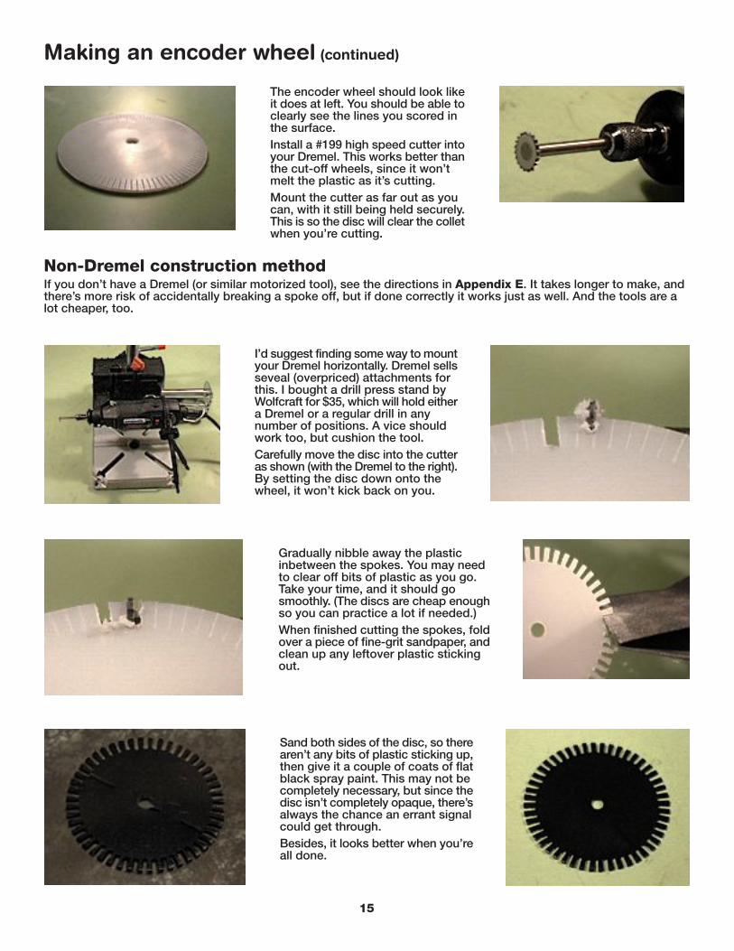
The encoder wheel should look likeit does at left. You should be able toclearly see the lines you scored inthe surface.Install a #199 high speed cutter intoyour Dremel. This works better thanthe cut-off wheels, since it won’tmelt the plastic as it’s cutting.Mount the cutter as far out as youcan, with it still being held securely.This is so the disc will clear the colletwhen you’re cutting.
Making an encoder wheel (continued)
I’d suggest finding some way to mountyour Dremel horizontally. Dremel sellsseveal (overpriced) attachments forthis. I bought a drill press stand byWolfcraft for $35, which will hold eithera Dremel or a regular drill in anynumber of positions. A vice shouldwork too, but cushion the tool.Carefully move the disc into the cutteras shown (with the Dremel to the right).By setting the disc down onto thewheel, it won’t kick back on you.
Gradually nibble away the plasticinbetween the spokes. You may needto clear off bits of plastic as you go.Take your time, and it should gosmoothly. (The discs are cheap enoughso you can practice a lot if needed.)When finished cutting the spokes, foldover a piece of fine-grit sandpaper, andclean up any leftover plastic stickingout.
Sand both sides of the disc, so therearen’t any bits of plastic sticking up,then give it a couple of coats of flatblack spray paint. This may not becompletely necessary, but since thedisc isn’t completely opaque, there’salways the chance an errant signalcould get through.Besides, it looks better when you’reall done.
15
Non-Dremel construction methodIf you don’t have a Dremel (or similar motorized tool), see the directions in Appendix E. It takes longer to make, andthere’s more risk of accidentally breaking a spoke off, but if done correctly it works just as well. And the tools are alot cheaper, too.

Next, check to see if it’s centered onthe shaft. To do this, line up one of thegaps in the disc with one of the holesin the plate. (If there’s no convenienthole on the plate, draw a small dot onit with the marker.)Spin the disc. You should be able tosee if the disc is centered by watchingthe spokes pass over the hole. The holedoesn’t need to remain perfectlycentered in the spokes, but it shouldbe close. If it’s not, loosen the nut andslide the disc over slightly, then tightenit back down. Keep repeating this untilit’s as centered as possible. You mayhave to slightly enlarge the hole in theencoder wheel to do this.
Making an encoder wheel (continued)
Place a 1/4” washer on the end of the shaft.Try to find the flattest one you can.Place the encoder wheel on the shaft, andthen another washer on after that. Again, tryto find a really flat one. Washers that aren’tflat can cause the encoder wheel to wobble.
Place two 1/4” jam nuts on theshaft, and tighten them down.Look at the encoder wheelfrom the side. Spin it aroundand be sure it isn’t wobbling.If it is, try replacing thewashers, and making sure thewashers and and encoder arecentered on the shaft. Thismay take a bit of fussing, buttry to make it spin as flatly aspossible.
16
Mouse brain surgery
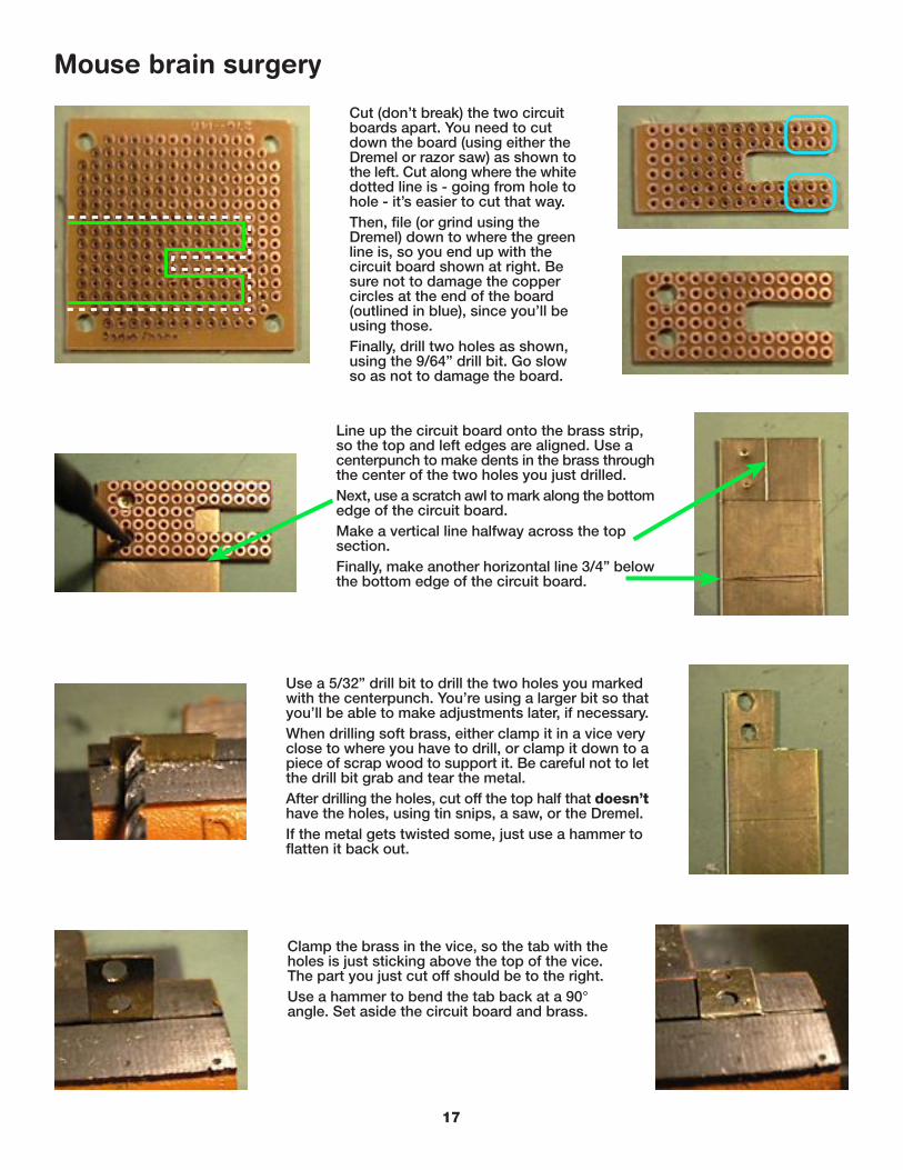
Cut (don’t break) the two circuitboards apart. You need to cutdown the board (using either theDremel or razor saw) as shown tothe left. Cut along where the whitedotted line is - going from hole tohole - it’s easier to cut that way.Then, file (or grind using theDremel) down to where the greenline is, so you end up with thecircuit board shown at right. Besure not to damage the coppercircles at the end of the board(outlined in blue), since you’ll beusing those.Finally, drill two holes as shown,using the 9/64” drill bit. Go slowso as not to damage the board.
Line up the circuit board onto the brass strip,so the top and left edges are aligned. Use acenterpunch to make dents in the brass throughthe center of the two holes you just drilled.Next, use a scratch awl to mark along the bottomedge of the circuit board.Make a vertical line halfway across the topsection.Finally, make another horizontal line 3/4” belowthe bottom edge of the circuit board.
Use a 5/32” drill bit to drill the two holes you markedwith the centerpunch. You’re using a larger bit so thatyou’ll be able to make adjustments later, if necessary.When drilling soft brass, either clamp it in a vice veryclose to where you have to drill, or clamp it down to apiece of scrap wood to support it. Be careful not to letthe drill bit grab and tear the metal.After drilling the holes, cut off the top half that doesn’thave the holes, using tin snips, a saw, or the Dremel.If the metal gets twisted some, just use a hammer toflatten it back out.
Clamp the brass in the vice, so the tab with theholes is just sticking above the top of the vice.The part you just cut off should be to the right.Use a hammer to bend the tab back at a 90°angle. Set aside the circuit board and brass.
17

Mouse brain surgery (continued)
Take your mouse apart. Generally, there will be oneor two screws. Sometimes hidden under labels orglides, as shown by the red circle. Once the screwsare out, usually you have to pry the back end of themouse up to pull it apart.
Removing the circuit boards is usually just a matterof lifting them straight off the plastic pegs. You mighthave to pop out the encoder wheels first though. Forthe mouse on the right, two screws had to be removed(circled in red).
Once the mouse isapart, you need tolocate the opticaltransmitter andreceiver pair forleft/right movement(circled in yellow).Depending on themouse, they’ll havetwo to four leadseach soldered tothe circuit board.To make the mouseeasier to work with,unplug the wiringharness (circled inblue).
What you’re going to do is removethe left/right transmitter and receiverand move them to the other circuitboard you made. Properlypositioning a new circuit board iseasier than trying to make themouse’s circuit board fit.Take note of the orientation andposition of the transmitter andreceiver before disassembling themouse. They have to face the samedirection when moved to the newboard.Some may have plastic covers onthem which make it harder to tellthem apart. You can temporarilyremove these, as shown.
18
USB circuit board
ADB circuit board

Flip the mouse over and circle thecomponents you need to removewith a marker (circled in yellowhere).You should also circle the mousebutton switch connections (circledin red), since you might as welldesolder them and get the switch(or switches) out of the way. If youever want to add a fire button, youcan just wire it in where the switchwent.For most of this example, I’ll justuse the USB mouse. The basicprinciples should apply to anymouse.Note: some of the photos in thisguide are of an earlier prototypewith different wiring. However, thephotos detailing the wiring processitself are up-to-date.
Mouse brain surgery (continued)
Use the desoldering iron (or other desoldering tool) to remove the solder from allof the connections you circled.A few tips on desolderingDesolder from the bottom of the circuit board where the little blobs of solder are -not from the side the components are on.Hold the iron against the little blob of solder that holds the component on. You’llfeel the iron “give” a little bit as soon as the solder melts - that’s when you releasethe squeeze bulb to suck the solder up.If you have trouble removing all of the solder, hold everything upside-down, andgravity will help pull the solder out of the hole better.Don’t hold the soldering iron in place too long - excessive heat can damage thecomponents. Attaching a small clip-on heat sink to the leads on the other side willhelp protect them.
Once you’ve gotten all of the componentsapart, be sure not to lose the transmitter andreceiver, and the plastic cover if there is one.
19
USB circuit board
ADB circuit board
If the component won’t come loose, butit looks like all of the solder has beenremoved, try to pop the stubborn leadfree with a small screwdriver.
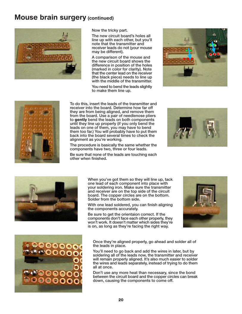
Now the tricky part.The new circuit board’s holes allline up with each other, but you’llnote that the transmitter andreceiver leads do not (your mousemay be different).A comparison of the mouse andthe new circuit board shows thedifference in position of the holes(marked in color for clarity). Notethat the center lead on the receiver(the black piece) needs to line upwith the middle of the transmitter.You need to bend the leads slightlyto make them line up.
Mouse brain surgery (continued)
To do this, insert the leads of the transmitter andreceiver into the board. Determine how far offthey are from being aligned, and remove themfrom the board. Use a pair of needlenose pliersto gently bend the leads on both componentsuntil they line up properly (if you only bend theleads on one of them, you may have to bendthem too far.) You will probably have to put themback into the board several times to check thealignment as you’re working.The procedure is basically the same whether thecomponents have two, three or four leads.Be sure that none of the leads are touching eachother when finished.
When you’ve got them so they will line up, tackone lead of each component into place withyour soldering iron. Make sure the transmitterand receiver are on the top side of the circuitboard. The copper circles are on the bottom.Solder from the bottom side.With one lead soldered, you can finish aligningthe components accurately.Be sure to get the orientaion correct. If thecomponents don’t face each other properly, theywon’t work. It doesn’t matter which sides they’reis on, as long as they’re facing the right way.
Once they’re aligned properly, go ahead and solder all ofthe leads in place.You’ll need to go back and add the wires in later, but bysoldering all of the leads now, the transmitter and receiverwill remain properly aligned. It’s also much easier to solderthe wires and leads separately, instead of trying to do themall at once.Don’t use any more heat than necessary, since the bondbetween the circuit board and the copper circles can breakdown, causing the components to come off.
20

Remove the outer sheath from the wireyou’re using (scrap category 5 ethernetcable is shown). Cut the wire to about6” to 8” in length.Untwist the pairs and set aside the onesyou don’t need. Strip about 1/2” of theinsulation off the end of each wire.
Mouse brain surgery (continued)
Push one wire through the circuit boardfrom the top side, and bend the barepart of the wire over at 90°.Using a pair of spring-loaded tweezers,clamp the wire down so the bare partis in contact with the copper circle it’ssticking through, and with the bead ofsolder on the closest lead.Note: If using components with morethan one row of leads, you’ll have tosolder the wires directly to the leads.
With it clamped in place,solder the wire first onto thecopper circle, then onto thebead of solder on the leadnext to it. By having itsoldered at two places, itmakes for a much strongerconnection.Repeat for all otherconnections, and trim offthe excess wire.If you nick or melt off someof the insulation, cover itwith electrical tape.
Set the new circuit board alongside themouse where the transmitter and receiverwere located, in the same orientation. Thiswill make it easier to keep the wires in thecorrect order.Strip the other ends of the wires, and pokethem through the holes in the mouse circuitboard where the transmitter and receiverused to be. Make sure the wires are goingto the correct holes that correspond to tothe ones on the new circuit board.
Solder the wires in place. Workon one component at a time soyou don’t have to juggle too manywires.Trim off any excess wire.Tie down the wires to the newcircuit board by looping leftoverwire across them and throughholes in the board. This will keepthem out of the way of theencoder wheel.
21
blue
orange green
blue/white
green/white

Use two of the 1/2” long #6-32screws to attach the circuitboard to the brass bracket. Theholes will be very close together,so the nuts may have to be linedup with their flat edges againsteach other.Hold the bracket in placeagainst the metal plate, so thecircuit board straddles theencoder wheel. I used a smallclip to hold it in place.The transmitter and receivershould be in line with, andperpendicular to, the center ofthe wheel (shown in green).
Mouse brain surgery (continued)
Check the alignment from theedge, and make sure theencoder wheel will clear thecircuit board when spun. If itdoesn’t, loosen the two screwsholding the circuit board to thebracket, and adjust it. If youneed to adjust it more, enlargethe bracket holes with a 3/16”bit.Looking straight on at theencoder wheel, be sure thetransmitter and receiver arecentered on the spokes.
Once it’s positioned correctly, markthrough one of the holes in the plateusing a scratch awl, onto the back ofthe bracket. Note: if there’s no holewhere the bracket is, you’ll have tomake one with the 9/64” bit.Remove the circuit board from thebracket, and drill the hole you justmarked on the bracket using the 5/32”bit.
Cut the bracket along the line youscratched into it earlier. File off anyrough edges.Reattach the circuit board to thebracket, then attach the bracket tothe plate using a 1/2" long #6-32screw, washer and nut.You’ll need needlenose pliers to holdthe nut between the two plates whiletightening the screw.
22

Realign the bracket. If you need to have more adjustment in thebracket’s position, enlarge the hole through it with the 3/16” bit.
Mouse brain surgery (continued)
Realign the circuit board as before. Be sure the encoder wheel willclear the circuit board and wires.
You’re now ready to take it for a test spin!Hook the wiring harness back up to the mouse circuit board, and plug it intoyour Mac.One nice benefit to Macs is they’ll allow multiple mice plugged in at the sametime, so you don’t need to unplug your current mouse to use the spinner.Grab ahold of the metal plates and give the knob a spin. If you did everythingright the cursor should move in the direction you spin the knob.Note: if using an ADB mouse, be sure to shut down the computer beforeplugging it in.
TroubleshootingBe sure to disable Kensington’s MouseWorks software, if installed.This software badly effects the performance of the spinner.Set the Mouse Control Panel speed to just above medium for anADB mouse. Set it to the fastest speed for USB.If the cursor moves up and down, you used the wrong transmitterand receiver pair. You’ll need to rewire accordingly, and may haveto reinstall the up/down transmitter and receiver in the mouse forit to work at all (it depends on how the mouse is designed).If the cursor moves in the wrong direction (left instead of right), youcan either remove the circuit board from the bracket and reinstallit upside down, or just leave it and use the “dial reverse” functionin MacMAME.If the cursor freaks out when you spin the knob fast, this is probablybecause of the mouse you started with. See “How the thing works”for more information. You can compensate for this a little bit withMacMAME’s “dial sensitivity” settings, but it may not help much.
23
Finishing it off
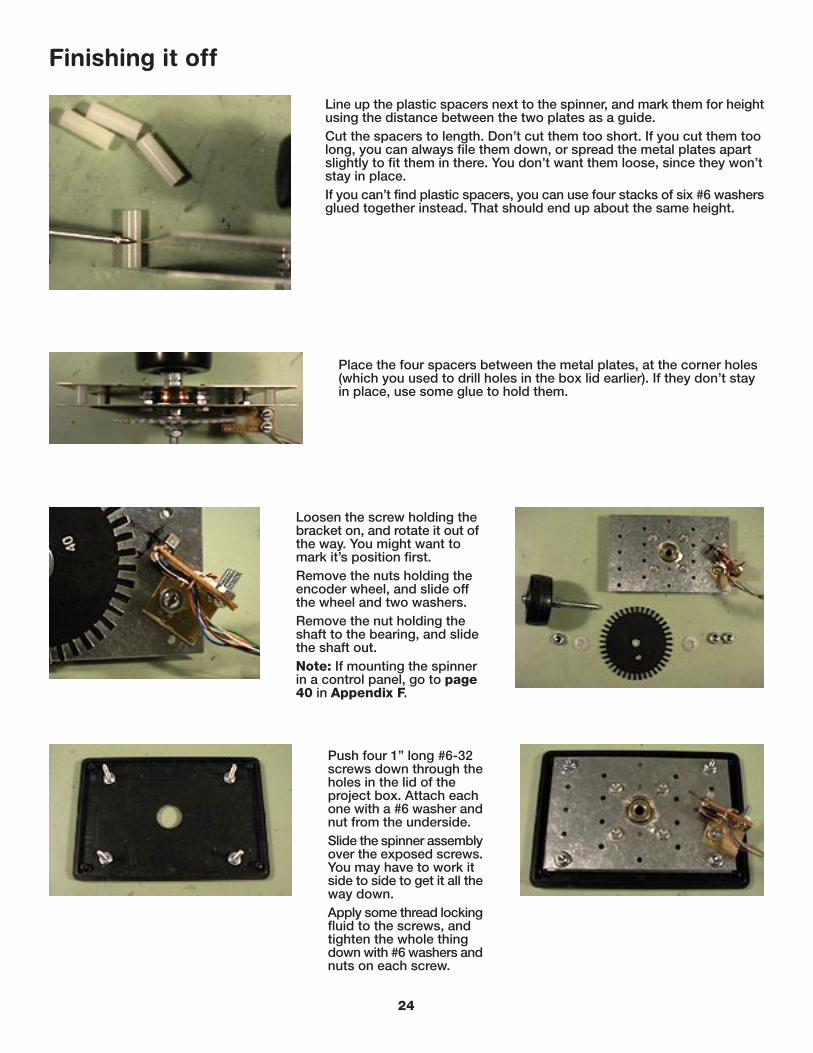
Line up the plastic spacers next to the spinner, and mark them for heightusing the distance between the two plates as a guide.Cut the spacers to length. Don’t cut them too short. If you cut them toolong, you can always file them down, or spread the metal plates apartslightly to fit them in there. You don’t want them loose, since they won’tstay in place.If you can’t find plastic spacers, you can use four stacks of six #6 washersglued together instead. That should end up about the same height.
Place the four spacers between the metal plates, at the corner holes(which you used to drill holes in the box lid earlier). If they don’t stayin place, use some glue to hold them.
Loosen the screw holding thebracket on, and rotate it out ofthe way. You might want tomark it’s position first.Remove the nuts holding theencoder wheel, and slide offthe wheel and two washers.Remove the nut holding theshaft to the bearing, and slidethe shaft out.Note: If mounting the spinnerin a control panel, go to page40 in Appendix F.
Push four 1” long #6-32screws down through theholes in the lid of theproject box. Attach eachone with a #6 washer andnut from the underside.Slide the spinner assemblyover the exposed screws.You may have to work itside to side to get it all theway down.Apply some thread lockingfluid to the screws, andtighten the whole thingdown with #6 washers andnuts on each screw.
24

Finishing it off (continued)
Find someplace in the box to mount thecircuit board. One of the bottom cornerswill work fine. You may need to file downthe short standoff on the bottom of thecase (circled in red) so you can fit thecircuit board all the way into the corner.You also need to cut a notch along theback of the case for the wire to fit through.Since the lid on this case actually fits downinto the box, you’ll need to cut it deeperthan if the lid sat on top.
Fit the circuit board into the corner of the case, so that the wiring harnessis next to one of the walls. The key here is to keep the wires away fromthe encoder wheel (or the counterweight, if you add one). In larger boxesor control panels, this isn’t so much of a problem.Drill a hole through the bottom of the box using the 9/64” bit. This is fora screw to hold the circuit board in place. Put the screw along the outeredge of the board someplace. Don’t drill through the circuit board.Doing so can damage the circuit traces on it, killing your spinner.
Put a 1/2” long #6-32 screwthrough the taped washer,and then down through thehole in the bottom of the box.Use some thread locking fluidand attach a #6 nut to thescrew from the underside ofthe box. Do not over-tightenit. The screw only needs tokeep the circuit board frombouncing around - it doesn’tneed to be tight. You maywant to cut the screw off if itsticks out too far.Attach the rubber feet to thebottom of the box. If theyattach with screws, be carefulto avoid the circuit board.
Take a small piece of electrical tape, and wrap it around a #6 washer,then poke a hole through the center with the scratch awl.The tape is there to insulate any exposed circuits from the washer.
25
Reattach the shaft and encoder wheel,and realign the bracket. Everything goesback together the way it was assembledthe first time.Make sure the encoder wheel doesn’twobble, and that the circuit board iscarefully aligned.Bundle up the wires going from themouse’s circuit board to the lidassembly. You can use plastic cableties or electrical tape. Bend the wiresso they’re as close to the side of thebox as possible.Thread the mouse cable going to thecomputer through the notch in the backof the box. Secure it in place with acable tie or tape.
Finishing it off (continued)
As you close the lid on the box, make sure the wires stay away fromthe encoder wheel. Stuff excess wire up between the two metal platesof the spinner assembly. Be sure the lid doesn’t pinch the wires whenyou close it.When you get the lid closed all the way, spin the knob slowly to besure the wheel isn’t catching any of the wires. If it is, open it back up,and try again. If you have to, tape the wires to the side of the box. Thecategory 5 wire is stiff enough so it should stay where you bend it.
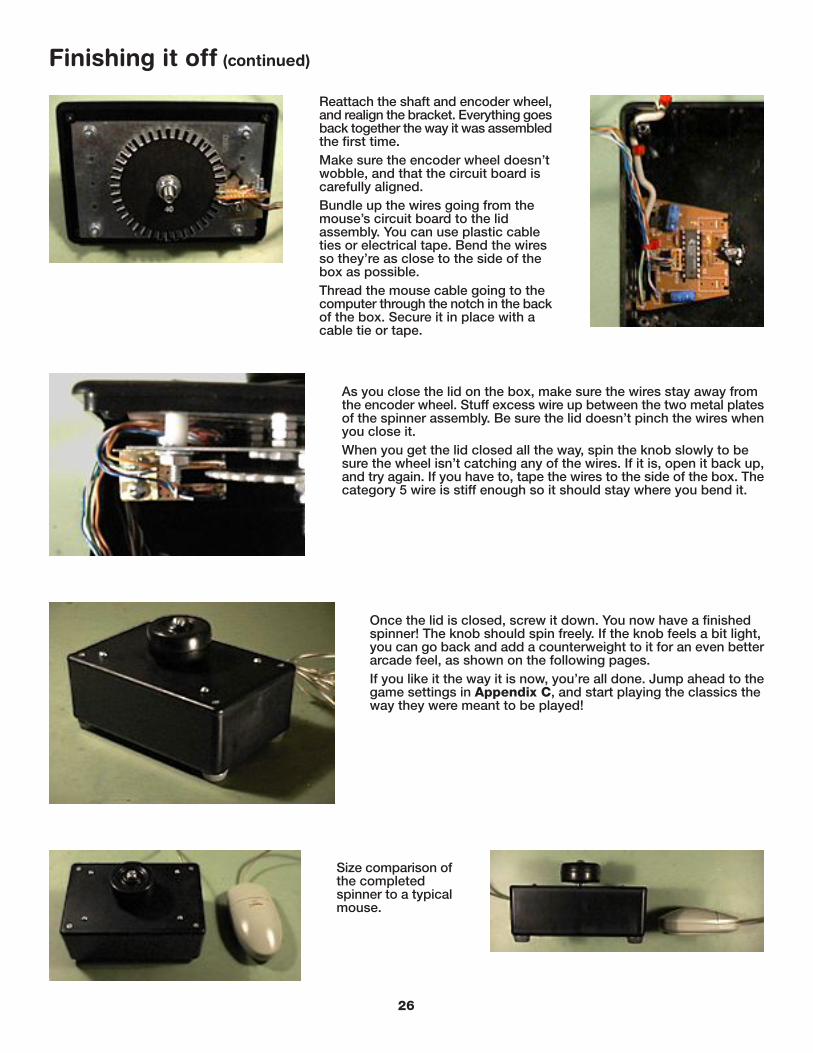
Once the lid is closed, screw it down. You now have a finishedspinner! The knob should spin freely. If the knob feels a bit light,you can go back and add a counterweight to it for an even betterarcade feel, as shown on the following pages.If you like it the way it is now, you’re all done. Jump ahead to thegame settings in Appendix C, and start playing the classics theway they were meant to be played!
Size comparison ofthe completedspinner to a typicalmouse.
26

If the knob feels a bit on the lightweight side, then you can adda counterweight in one of several ways.If you just want to add a little weight, you can remove the secondnut below the encoder wheel, and stack a few 1 1/4” diameter1/4” fender washers (not shown) on the bottom of the shaft, thenput the nut back on with some thread locking fluid.If you’re really after that weighty arcade feel though, you needto put a hefty counterweight on.Measure, centerpunch and drill a hole dead-center in the 3 9/16”round blank electrical box cover, using the 1/4” drill bit.
Appendix A - Adding a counterweight
Put a 1/4” washer on the end of the shaft, after the two 1/4” jamnuts that are on there. Then the steel disc, and then two more jamnuts.As with the encoder wheel, you may have to try a different washer,or rotate the position of the disc in order for it to spin flat. This isimportant because you want it to be as balanced as possible, plusyou don’t want it to hit your circuit board.Give it a test spin to check the balance and clearance. If you wanteven more weight, add some fender washers or a second steel disc.
The disc is going to barely fit into the small project box. If you’re addingthis counterweight, you might want to consider a larger box.If the spinner assembly isn’t centered on the box lid, then thecounterweight probably won’t fit into the box.
Use the same wire-stuffing method from before to close the lid.You will have to drop the lid almost straight down into the box forthe counterweight to fit.Once you get the box closed, spin the knob slowly to be sure it’snot catching on any wires. You may hear it scraping the inside ofthe box, but as long as you can spin it, the scraping can be fixed.If it won’t move (or fit) at all, use fender washers instead.
If it does scrape, you’ll need to estimate how far off the bottomit’s hitting, then use a file (or Dremel) to cut away the circuit boardguides that stick out from the sides of the box. You may have torepeat this process several times to get it to clear.
27

Appendix B - Relubricating the spinner
If you need to relubricatethe spinner, you eitherneed to take it apart soyou can get at thebearings from below, oryou can add a hole whilebuilding the spinner thatwill let you do it withouttaking anything apart.To add the hole, you’llneed to be to the point inconstruction where you’vejust attached the spinnerassembly to the lid, asshown.
Use the 3/32” drill bit and start thehole by drilling straight downabout 3/8” away from the edge ofthe center hole.As soon as the drill bit bites intothe plastic, angle it over towardsthe bearing. Drill slowly so youdon’t damage the bearing with thedrill. You want the drill to end uppointing right at the edge of thebearing. Be sure to clean out anyplastic debris before finishing therest of the spinner.
Check the hole by sticking thetube from the WD-40 can in it.It should bottom out right at theedge of the bearing. This will letyou relube the spinner from thetop without taking anythingapart. (For clarity, I took thepictures with the knob removed,but you can easily fit the tubeunder the edge of the knob.)Note: Use very little WD-40when relubricating the bearings.Otherwise you’ll end up with abig mess inside the spinner. Youonly need a tiny little squirt todo the job - not a full spray.Practice first before sprayinglube into the spinner.
28
Stand-alone versionControl-panel version
The same procedure applies tothe aluminum plate used forcontrol panel mounting.However, with the aluminumplate it’s especially important toremove the spinner assemblyand clean out any metalshavings, and also file down therough edges on the bottom sideof the aluminum.

Appendix C - Game settings
These are some of the games I’ve tried out with the ADB and USB versions of the Cheep Spinner. I’ve listed the dialsensitivity settings that seem to work well in MacMAME, as well as the type of control used on the original game, andsome keyboard settings that I like to use. I also added a few notes about how each game works with the spinner.Your mileage may vary, depending on the mouse you start with, and the type of “feel” you’re looking for. Of course,there are a lot of games not listed here that work too: Cosmic Chasm, Zektor, Boxing Bugs, Speed Freak, etc.
Arkanoid - right-handed spinner47% sensitivity - ADB85% sensitivity - USBkeyscontrol = firenotesRequires accurate movment, not spinning. This is the hardest game toadjust the sensitivy to be “just right”.
Blasteroids - left-handed spinner65% sensitivity - ADB85% sensitivity - USBkeysperiod = firecomma = thrustspace = transformnotesThe ship you choose determines how fast it will spin. If you choose thelarge ship, you can spin the knob for all your worth and it won’t spinvery fast, but that’s part of the game. It plays great on a fast enoughMac.
Discs of Tron - left-handed spinner with three-position axis50% sensitivity - ADB50% sensitivity - USBkeysrequires a trigger joystick with three buttons to be playable - the up/downmovement of the knob can be mapped to one of the buttonsnotesThe spinner works fine, but without a suitable joystick, you can’t block,or move from level to level. You could add two fire buttons right nextto the spinner for those functions, but you would still need a triggerjoystick to move and fire at the same time.
29

Appendix C - Game settings (continued)
Demolition Derby - steering wheel40% sensitivity (dial reverse is on) - ADB60% sensitivity (dial reverse is on) - USBkeyscontrol = forwardoption = backwardnotesFun game! Reversing the dial direction makes it much easier to drivearound backwards, which is the key to winning.
Ironman Stewart’sSuper Off-Road - steering wheel100% sensitivity - ADB130% sensitivity - USBkeyscontrol = pedaloption = nitronotesBy default, the Nitro button is mapped to the same key used for thepedal. You need to remap one or the other, or you’ll use up your Nitrowhen you hit the gas. Once you sort that out though, it plays great!
Mad Planets - left-handed spinner7% sensitivity - ADB25% sensitivity - USBkeysrequires a trigger joystick to be playablenotesNeeds very low sensitivity, since there are only a few positions that theship rotates to. This is one of the great unsung games of the end of theclassic era, there are few thrills like circling around a planet while keepingthe nose pointed straight into it, and blasting away!
30
Appendix C - Game settings (continued)
Major Havoc - right-handed spinner90% sensitivity - ADB170% sensitivity - USBkeyscontrol = fire/jumpoption = shieldnotesOnce I got the settings right for this, it was like playing a whole newgame. Control makes all the difference here, and you can finally getthrough the mazes with both precision and speed.
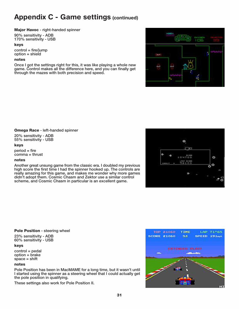
Pole Position - steering wheel23% sensitivity - ADB60% sensitivity - USBkeyscontrol = pedaloption = brakespace = shiftnotesPole Position has been in MacMAME for a long time, but it wasn’t untilI started using the spinner as a steering wheel that I could actually getthe pole position in qualifying.These settings also work for Pole Position II.
Omega Race - left-handed spinner20% sensitivity - ADB55% sensitivity - USBkeysperiod = firecomma = thrustnotesAnother great unsung game from the classic era. I doubled my previoushigh score the first time I had the spinner hooked up. The controls arereally amazing for this game, and makes me wonder why more gamesdidn’t adopt them. Cosmic Chasm and Zektor use a similar controlscheme, and Cosmic Chasm in particular is an excellent game.
31

Tac Scan - right-handed spinner60% sensitivity - ADB115% sensitivity - USBkeyscontrol = fireoption = add shipnotesAnother vector classic. If you aren’t playing Tac Scan, you don’t knowwhat you’re missing. The spinner finally brings back the kind of controlthat really makes this game shine - even flying through the rings betweenlevels is a snap. As with Omega Race, I doubled my previous high scoreonce I was using the spinner.
Appendix C - Game settings (continued)
Super Sprint - steering wheel25% sensitivity - ADB45% sensitivity - USBkeyscontrol = pedalnotesI never played this in MacMAME much, since it was nearly impossibleto steer. The spinner solves that problem nicely.
Star Trek - left-handed spinner70% sensitivity - ADB130% sensitivity - USBkeysperiod = firecomma = thrustspace = photonm = warpnotesNot the most popular vector game, but I like it (maybe because it’ssimilar to Battlezone, which is my favorite game). The spinner allowsyou to aim and steer far better than a mouse.
32
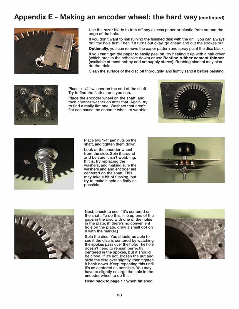
Turbo - steering wheel75% sensitivity - ADB125% sensitivity - USBkeyscontrol = pedaloption = brakespace = shiftnotesThis, along with Arkanoid, is the toughest game to set the sensitivityon. Once you get it though, it’s great! The trick is to set it so you canmove quickly and precisely from lane to lane with just a twitch of theknob.A quick game tip: don’t keep the accelerator floored all the time. Justgo fast enough to pass enough cars to extend your time.
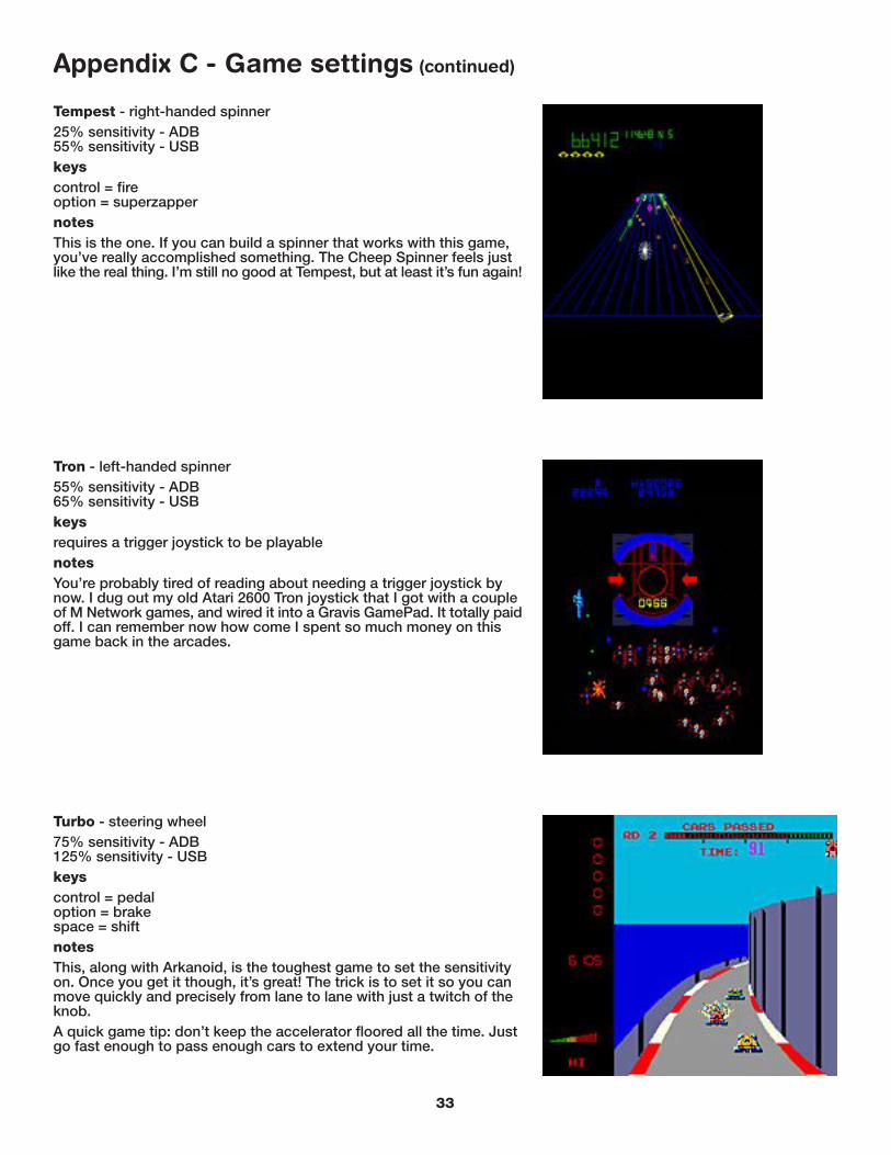
Tempest - right-handed spinner25% sensitivity - ADB55% sensitivity - USBkeyscontrol = fireoption = superzappernotesThis is the one. If you can build a spinner that works with this game,you’ve really accomplished something. The Cheep Spinner feels justlike the real thing. I’m still no good at Tempest, but at least it’s fun again!
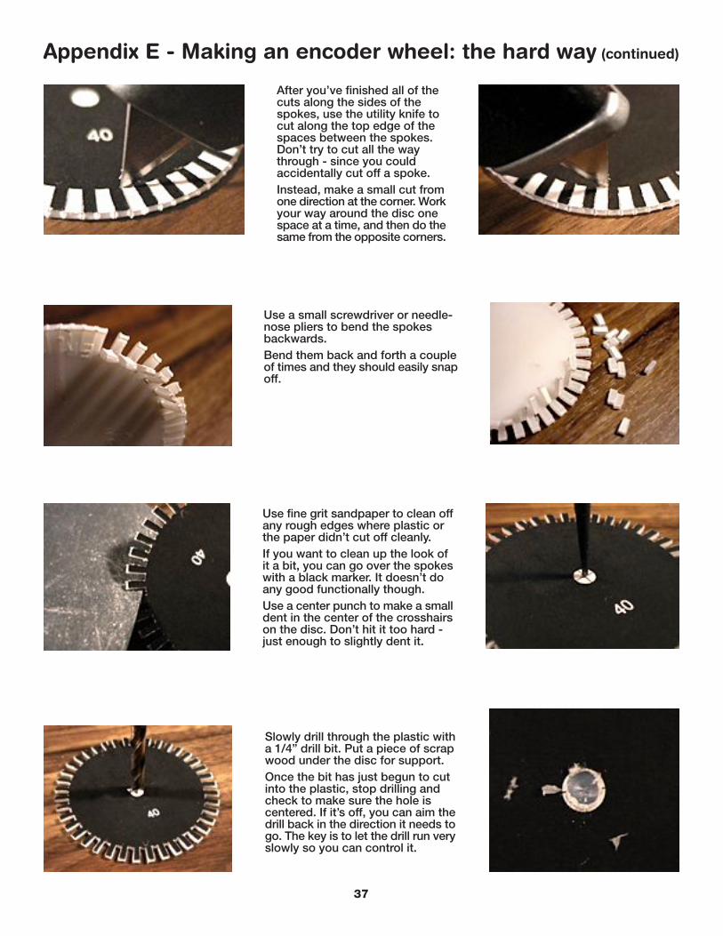
Tron - left-handed spinner55% sensitivity - ADB65% sensitivity - USBkeysrequires a trigger joystick to be playablenotesYou’re probably tired of reading about needing a trigger joystick bynow. I dug out my old Atari 2600 Tron joystick that I got with a coupleof M Network games, and wired it into a Gravis GamePad. It totally paidoff. I can remember now how come I spent so much money on thisgame back in the arcades.
Appendix C - Game settings (continued)
33

Appendix D - Encoder wheels
Print this page out at 100%. Acrobat will sometimes shrink pages to fit, so be sure to check your Page Setup. Thediscs should be 3” across when printed out. I’ve added a ruler to help gauge it.Basically, the rule of thumb is: the more spokes, the more sensitive the spinner will be. However, it may also be moreprone to the “strobing” effect mentioned in “How the thing works”. Too few spokes though, and you’ll have to spinthe knob farther than you might like in order to get any movement. The happy medium for the SuperMac ADB mousementioned in this guide seems to be the 40 spoke wheel. For the Kensington USB ValuMouse, the 48 spoke wheelworks best. Of course, which works best all depends on the mouse you start with.One final note: instead of making an encoder wheel as shown in the guide, you could print this out on a transparency,and glue that to a smaller diameter disc so the spokes stick out over the edge. The only drawback is if the toner orink that your printer uses isn’t opaque enough, it won’t interrupt the infrared signal reliably.
40
3224
48
34
1 2 3 4 5 6 7

Appendix E - Making an encoder wheel: the hard way
Take the ABS plastic testcap, and use a pair ofpliers or an adjustablewrench to remove theedge of the rim. Work ashort section back andforth a few times, until itbreaks free, and do thisall the way around.
Use tin snips or a finetoothed saw to make cutsall the way around the rim,about 1/4” apart.Then, use the pliers again tobreak off the pieces.
If your cap has a couple oftabs on it (some don’t), usethe razor saw to trim themoff. File down any remainsthat stick up.
Use a file and sandpaper to smoothoff the rough edges around the disc.The caps are pre-scored most of theway around, so it should be prettyeasy to remove the rim and end upwith a good round disc.Peel off the UPC sticker if there is one.If there’s any raised lettering, makesure it’s filed off (you only need oneside completely smooth - the otheronly needs to be smooth around thecenter where the washer will sit).
35

Appendix E - Making an encoder wheel: the hard way (continued)
Print out the page (Appendix C) withthe encoder wheels on it, and cut oneof them out. See “How the thing works”for more information. Trim carefullyalong the outer edge of the spokes -do not cut out the spaces betweenthe spokes yet.Spray adhesive on the back of thepaper disc.Stick the paper disc onto the plasticone, lining them up so they’re centered.Smooth out any bumps or air bubbles.
After the adhesive sets up, use a razor totrim any excess paper from the edge of thedisc.Place the disc under a desk lamp for a fewminutes, paper side up. This will warm itup and slightly soften the plastic. You don’twant to leave it under there too long, or theadhesive will start breaking down. Warmingthe disc up makes it a lot easier to cut.
Use a sharp utility knife (orX-acto knife with a stiffblade) to cut along the edgesof the spokes. Don’t try tocut all the way through - itcould cause the plastic tocrack. If the disc is warmedup, you can cut abouthalfway through. You mayneed to rewarm the disc fromtime to time as you goaround the edge.Pictured at right is what theback of the disc looks likeafter going around once withthe knife.
After you’ve gone all the way aroundonce, warm up the disc again.Then, use the razor blade and pushit from the disc’s edge into the partialcuts you just made to completethem. Since the blade is so thin,there’s less chance of cracking theplastic this way.You may need to rock the bladeback and forth as you push. Supportthe disc by holding it over the edgeof a table.
36
After you’ve finished all of thecuts along the sides of thespokes, use the utility knife tocut along the top edge of thespaces between the spokes.Don’t try to cut all the waythrough - since you couldaccidentally cut off a spoke.Instead, make a small cut fromone direction at the corner. Workyour way around the disc onespace at a time, and then do thesame from the opposite corners.
Appendix E - Making an encoder wheel: the hard way (continued)
Use a small screwdriver or needle-nose pliers to bend the spokesbackwards.Bend them back and forth a coupleof times and they should easily snapoff.
Use fine grit sandpaper to clean offany rough edges where plastic orthe paper didn’t cut off cleanly.If you want to clean up the look ofit a bit, you can go over the spokeswith a black marker. It doesn’t doany good functionally though.Use a center punch to make a smalldent in the center of the crosshairson the disc. Don’t hit it too hard -just enough to slightly dent it.
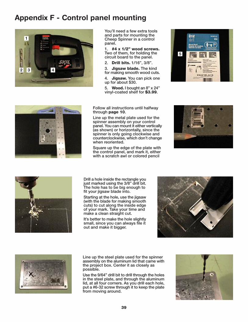
Slowly drill through the plastic witha 1/4” drill bit. Put a piece of scrapwood under the disc for support.Once the bit has just begun to cutinto the plastic, stop drilling andcheck to make sure the hole iscentered. If it’s off, you can aim thedrill back in the direction it needs togo. The key is to let the drill run veryslowly so you can control it.
37
Use the razor blade to trim off any excess paper or plastic from around theedge of the hole.If you don’t want to risk ruining the finished disk with the drill, you can alwaysdrill the hole first. Then if it turns out okay, go ahead and cut the spokes out.Optionally, you can remove the paper pattern and spray paint the disc black.If you can’t get the paper to easily peel off, try heating it up with a hair dryer(which breaks the adhesive down) or use Bestine rubber cement thinner(available at most hobby and art supply stores). Rubbing alcohol may alsodo the trick.Clean the surface of the disc off thoroughly, and lightly sand it before painting.
Next, check to see if it’s centered onthe shaft. To do this, line up one of thegaps in the disc with one of the holesin the plate. (If there’s no convenienthole on the plate, draw a small dot onit with the marker.)Spin the disc. You should be able tosee if the disc is centered by watchingthe spokes pass over the hole. The holedoesn’t need to remain perfectlycentered in the spokes, but it shouldbe close. If it’s not, loosen the nut andslide the disc over slightly, then tightenit back down. Keep repeating this untilit’s as centered as possible. You mayhave to slightly enlarge the hole in theencoder wheel to do this.Head back to page 17 when finished.
Appendix E - Making an encoder wheel: the hard way (continued)
Place a 1/4” washer on the end of the shaft.Try to find the flattest one you can.Place the encoder wheel on the shaft, andthen another washer on after that. Again, tryto find a really flat one. Washers that aren’tflat can cause the encoder wheel to wobble.
Place two 1/4” jam nuts on theshaft, and tighten them down.Look at the encoder wheelfrom the side. Spin it aroundand be sure it isn’t wobbling.If it is, try replacing thewashers, and making sure thewashers and and encoder arecentered on the shaft. Thismay take a bit of fussing, buttry to make it spin as flatly aspossible.
38
Appendix F - Control panel mounting
You’ll need a few extra toolsand parts for mounting theCheep Spinner in a controlpanel.1. #4 x 1/2” wood screws.Two of them, for holding thecircuit board to the panel.2. Drill bits. 1/16”, 3/8”.3. Jigsaw blade. The kindfor making smooth wood cuts.4. Jigsaw. You can pick oneup for about $30.5. Wood. I bought an 8” x 24”vinyl-coated shelf for $3.99.
Follow all instructions until halfwaythrough page 10.Line up the metal plate used for thespinner assembly on your controlpanel. You can mount it either vertically(as shown) or horizontally, since thespinner is only going clockwise andcounterclockwise, which don’t changewhen reoriented.Square up the edge of the plate withthe control panel, and mark it, eitherwith a scratch awl or colored pencil
Drill a hole inside the rectangle youjust marked using the 3/8” drill bit.The hole has to be big enough tofit your jigsaw blade into.Starting at the hole, use the jigsaw(with the blade for making smoothcuts) to cut along the inside edgeof your mark. Take your time andmake a clean straight cut.It’s better to make the hole slightlysmall, since you can always file itout and make it bigger.
Line up the steel plate used for the spinnerassembly on the aluminum lid that came withthe project box. Center it as closely aspossible.Use the 9/64” drill bit to drill through the holesin the steel plate, and through the aluminumlid, at all four corners. As you drill each hole,put a #6-32 screw through it to keep the platefrom moving around.
39
1
2 3 4
5
Appendix F - Control panel mounting (continued)
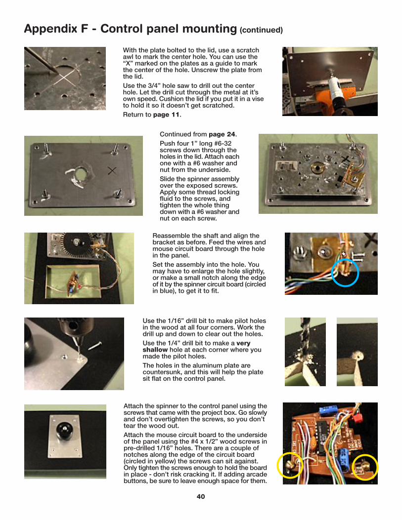
With the plate bolted to the lid, use a scratchawl to mark the center hole. You can use the“X” marked on the plates as a guide to markthe center of the hole. Unscrew the plate fromthe lid.Use the 3/4” hole saw to drill out the centerhole. Let the drill cut through the metal at it’sown speed. Cushion the lid if you put it in a viseto hold it so it doesn’t get scratched.Return to page 11.
Continued from page 24.Push four 1” long #6-32screws down through theholes in the lid. Attach eachone with a #6 washer andnut from the underside.Slide the spinner assemblyover the exposed screws.Apply some thread lockingfluid to the screws, andtighten the whole thingdown with a #6 washer andnut on each screw.
Reassemble the shaft and align thebracket as before. Feed the wires andmouse circuit board through the holein the panel.Set the assembly into the hole. Youmay have to enlarge the hole slightly,or make a small notch along the edgeof it by the spinner circuit board (circledin blue), to get it to fit.
Attach the spinner to the control panel using thescrews that came with the project box. Go slowlyand don’t overtighten the screws, so you don’ttear the wood out.Attach the mouse circuit board to the undersideof the panel using the #4 x 1/2” wood screws inpre-drilled 1/16” holes. There are a couple ofnotches along the edge of the circuit board(circled in yellow) the screws can sit against.Only tighten the screws enough to hold the boardin place - don’t risk cracking it. If adding arcadebuttons, be sure to leave enough space for them.
40
Use the 1/16” drill bit to make pilot holesin the wood at all four corners. Work thedrill up and down to clear out the holes.Use the 1/4” drill bit to make a veryshallow hole at each corner where youmade the pilot holes.The holes in the aluminum plate arecountersunk, and this will help the platesit flat on the control panel.

Appendix F - Control panel mounting (continued)
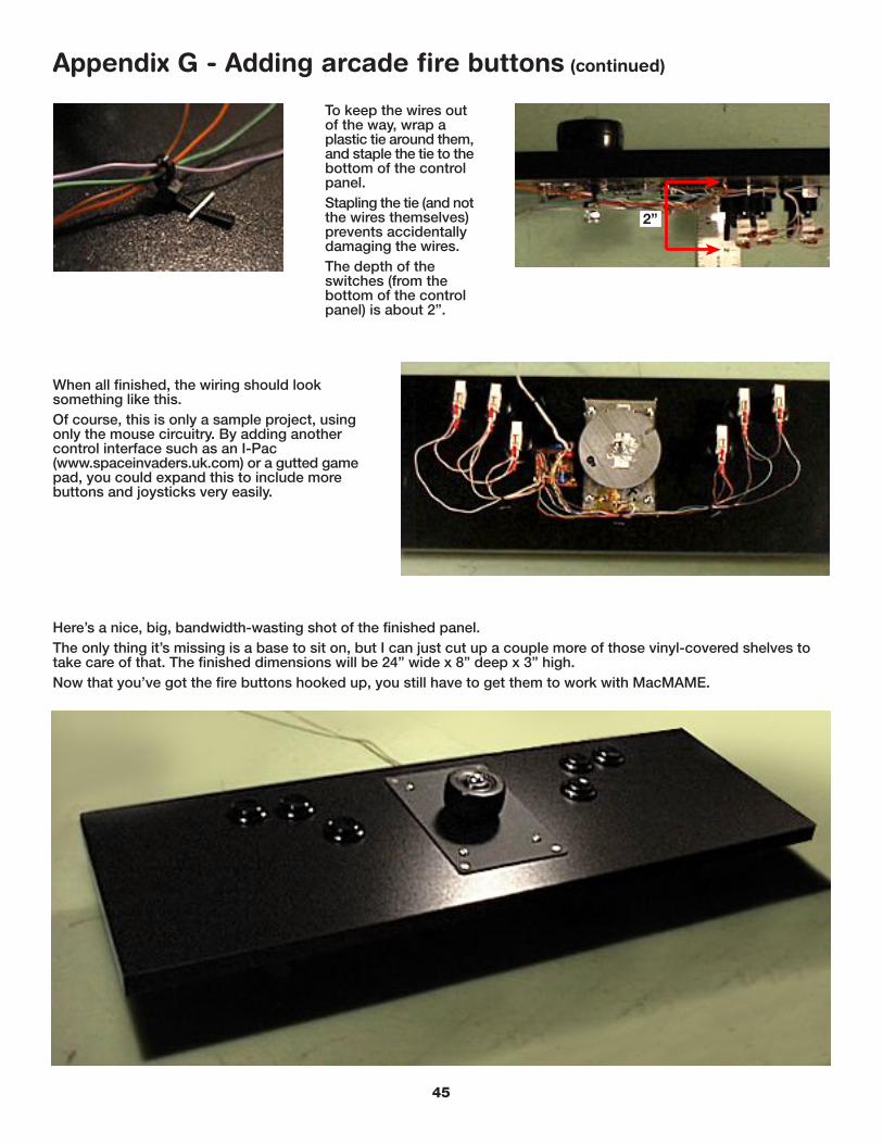
To keep the wires out ofthe way, wrap a plastic tiearound them, and staplethe tie to the bottom of thecontrol panel.Stapling the tie (and notthe wires themselves)prevents accidentallydamaging the wires.
For contact paper, after drilling the holes inthe plate, clean off the plate thoroughly withrubbing alcohol, and set it face down on thecontact paper.Trim the paper so it’s about 1/2” past the edgeof the plate, and cut the corners as shown.
Peel off the backing, and stick the plate down onthe contact paper - being sure it’s centered.Fold over the bottom and top edges, then thesides, and finally the corners. Trim the excess fromaround the bottoms of the screw holes with an X-acto knife or razor blade (outlined in red).Use an X-acto or razor to cut out the center hole.
From the top side, use a scratch awl to pokethrough the screw holes (and the WD-40hole, if you made one). Be sure the WD-40tube will still fit - trim excess paper fromthe hole if needed.Smooth out the paper, removing anywrinkles and air bubbles. Then assemblethe spinner as shown stating on page 40.
41
Customizing the look of the spinnerYou can customize the look of the spinner either by spray-painting or using contact paper on the aluminum plate.If spray painting, clean the surface thoroughly (after drilling all of the holes) with rubbing alcohol, then follow thedirections on the paint can. Be sure to get paint for metal. You may also need to use a coat of primer first.
2”
Follow the directions inAppendix A if you wantto add a counterweight.The spinner is onlyabout 2” deep from thetop of the panel to thebottom of the shaft, soit will work in veryshallow control panels.

Appendix G - Adding arcade fire buttons
You’ll need a few more tools and parts:1. 1 1/8” hole saw. You should beable to use the mandrel from the holesaw you used for the spinner, to savesome money. $7.462. Crimping tool. For solderlesscrimp-type connectors. $5.993. Female crimp-typedisconnects. .25”, 22 - 18 gauge wire$7.99 (box of 100).4 - 5. Staple gun and 5/16”staples. Yes, it’s really that color.Guess which decade it’s from.
6. Arcade fire buttons. Theseare from HappControls.com, andcost $1.45 each.For this example, I decided tohook up six buttons. I used 1 1/4”fender washers to layout thebuttons where I’d want them.These work well since they’reabout the right size, and have ahandy hole in the center formarking their positions.
Once you get thebuttons laid out, drilla 1/4” hole at eachlocation. Then usethe 1 1/8” hole sawto cut each hole.You’ll need to clearoff the saw teethevery few seconds inorder to keep themfrom getting clogged.
Once the holes are drilled, install thebuttons. They attach with a nylon nutthat screws on from beneath.Since the mouse only has threeswitches, I decided to wire thebuttons up in parallel, so the buttonson the left mirror the buttons on theright. This lets me play left or righthanded spinner games without anyextra control interface.
Cut off about 24” of category 5ethernet cable, and strip thesheathing off. Strip about 1/2” ofinsulation off one end of each wire.
42
Close-up of femalecrimp-type disconnect
1 2
3
5
4
6
Left button
Middle button
Right button

Appendix G - Adding arcade fire buttons (continued)
Take the wires in pairs (blue andblue/white, etc.) and put themthrough the holes in the circuitboard where the mouse buttonswitches were.In this example, orange is left, greenis middle, blue is right, and brownis common. If this seemsbackwards, you’re looking at theboard from underneath.Solder the wires in place, and trimoff the excess.
Install the switches ontothe bottom of the buttons.They fit over a small pivotpin, then swing down andsnap into place.Make sure the switchesare oriented so that it’seasy to get to all of theterminals on them.
Attach the circuit board to theunderside of the panel asdescribed on page 40.Take the other end of the wires,and run them over to thebuttons. Use the diagrambelow as a guide, and wrap thewires around the buttons tokeep them out of the way untilyou need them.Note that brown and orangewires are going to the samebuttons.
43
blue pair
orange pairgreen pairbrown pair
blue
orange andbrown
green
blue/white
green/white
orange/white andbrown/white
When running the wires, be sure to run themaround the spinner, leaving enough clearanceso that the encoder wheel and counterweightdon’t hit any of them.

Appendix G - Adding arcade fire buttons (continued)
One at a time, cut all exceptthe common (brown) wires tolength - so they easily reachthe terminals on the switches.Strip 1/2” of insulation off ofthem, and double them overas shown.Insert each one into adisconnect and crimp it so thewire is firmly held in place.
Slip the disconnect onto the middleterminal of the switch.If the disconnect is loose, slide itback off, then use a pair of pliersto squeeze it a little bit, and tryagain until it fits on snugly.
Repeat this process for all wires, except thecommon (brown) wires.For the brown wires, cut them to length so theyreach the switches nearest to the circuit board(where the orange wire is, in this example).Cut the leftover brown wires into approximately6” lengths. Strip 1/4” of insulation off all theends.Take the end of the brown wire coming out ofthe circuit board, and twist it together with theend of one of the 6” pieces. Insert them into adisconnect and crimp it.
Repeat this process by crimpinga second 6” piece with the end ofthe previous one. On the end ofthe second piece, strip 1/2” ofinsulation off, double it over, andcrimp a disconnect onto the endof it. You should end up withsomething similar to what’s shownat left.Connect the disconnect to theterminals on the top of the switches(it’s actually the bottom of theswitches, but you’re looking atthem upside down).Be sure to repeat these steps forthe other three buttons, using thebrown/white wires.
44
Appendix G - Adding arcade fire buttons (continued)
To keep the wires outof the way, wrap aplastic tie around them,and staple the tie to thebottom of the controlpanel.Stapling the tie (and notthe wires themselves)prevents accidentallydamaging the wires.The depth of theswitches (from thebottom of the controlpanel) is about 2”.
When all finished, the wiring should looksomething like this.Of course, this is only a sample project, usingonly the mouse circuitry. By adding anothercontrol interface such as an I-Pac(www.spaceinvaders.uk.com) or a gutted gamepad, you could expand this to include morebuttons and joysticks very easily.
45
2”
Here’s a nice, big, bandwidth-wasting shot of the finished panel.The only thing it’s missing is a base to sit on, but I can just cut up a couple more of those vinyl-covered shelves totake care of that. The finished dimensions will be 24” wide x 8” deep x 3” high.Now that you’ve got the fire buttons hooked up, you still have to get them to work with MacMAME.

Appendix G - Adding arcade fire buttons (continued)
You currently can’t assign mouse buttons to individual controls using the TAB menu within MacMAME. Instead, youhave to use InputSprockets from the MacMAME front-end. The mouse buttons will work without doing this, but they’llall do the same thing, which is to be the default fire button.
46
First, make sure that you’ve gotInputSprocket Mouse, InputSprocket USBand InputSprocketLib enabled in ExtensionsManager.Note: be sure Kensington Startup is disabled,if you have Kensington MouseWorkssoftware installed. USB Overdrive may alsocause the Cheep Spinner to work incorrectly.
Select the “Misc” tab in the MacMAME front-end. At the bottom, check “UseInputSprocket for mouse” and click“Configure InputSprocket…”
I’d suggest leaving the sensitivity settings alone, or at least remembering where it is, so you can reset it later if needed.You assign controls to each button by clicking on the “zap” icons next to each button name, and scrolling down thelist of controls that pops up. If you want to change button assignments, you must do that here, before launching thenext game you want to play. The TAB menu will not let you do this with mice, and therefore it won’t let you do it withthe Cheep Spinner. (This is as of MacMAME .37 beta 11, although it could change later.)

Since I improved on the design of the Cheep Spinner since theprototype, I decided to move the prototype’s ADB guts over to theUSB spinner I made for this guide. I wouldn’t have bothered, exceptI didn’t have a USB Mac at home at the time.Instead of discarding the USB parts though, I just added the ADBparts to the other side of the spinner assembly (note that the bracketis upside down). The result is a spinner that works with either ADBor USB Macs.I suppose the same method could be used to make a Mac/PCspinner. But that’s something that will have to be figured out bysomeone else.
Appendix H - Variations on a theme
This is a look at the original prototype spinner I built. It used aSuperMac ADB mouse and worked pretty well, but the encoderwheel response was too slow, since the spokes were too few andfar apart. In case you’re wondering, the encoder wheel is the bottomof a sink strainer, with extra holes drilled in it. Not terribly elegant.You can also see the larger size of the box used for it. Everythingelse - the metal plates, the knob, the bracket, are all the same onesused in this guide.The larger box works fine, but seems slightly top-heavy. This canprobably be dealt with by gluing some weight (pieces of steel) tothe inside bottom of it with some epoxy.
Also on the prototype, I used a second caster wheel as thecounterweight. This worked really well, but took up toomuch space to fit in the smaller project box. They also sellcaster wheels that are solid metal that would make for veryheavy counterweights indeed.
To my surprise, it all fit inthe smaller box, includingthe steel counterweight.All together, I probably builtthe equivilant of about fourspinners before nailing thedesign down to what it isnow. I’ve since re-fitted theprototype with the USBparts shown in this guideand a new encoder wheel,and kept only the ADBversion in the smaller box,which is what I use.
47