hussman rack installation manual
TRANSCRIPT

Installation & Service Manual
P/N 0427598_B July 2013IMPORTANT
Keep in store forfuture reference!
Parallel RackSystems


Parallel Rack
P/N 0427598_B iii
HUSSMANN CORPORATION • SUWANEE, GA 30024 U.S.A.
INSTALLATION
Shipping Damage . . . . . . . . . . . . . . . . . . . . 1-1General Rack Description . . . . . . . . . . . . . 1-1General Rack Components . . . . . . . . . . . . 1-2Remote Satellite Components . . . . . . . . . . 1-2Legend, Labels, & Wiring Diagrams . . . . . 1-2Setup Sheet . . . . . . . . . . . . . . . . . . . . . . . . . 1-2Machine Room Requirements . . . . . . . . . . 1-3Handling . . . . . . . . . . . . . . . . . . . . . . . . . . . 1-3Rack Unit Placement . . . . . . . . . . . . . . . . . 1-4Minimum Allowable Distances . . . . . . . . . . . . . . 1-4
Maximum Allowable Distances . . . . . . . . . . . . . . . 1-4
Ventilation . . . . . . . . . . . . . . . . . . . . . . . . . 1-5Floor Drain . . . . . . . . . . . . . . . . . . . . . . . . 1-5Remote Condenser Placement . . . . . . . . . . 1-6Installing Vibration Pads . . . . . . . . . . . . . . 1-6Rack Sizing Charts . . . . . . . . . . . . . . . . . . . 1-7Defrost Header Planning Charts . . . . . . . . 1-8
COMPONENT PIPING & LINE SIZING
Rack Piping Overview . . . . . . . . . . . . . . . . 2-1Refrigeration Line Runs . . . . . . . . . . . . . . . 2-1Insulation . . . . . . . . . . . . . . . . . . . . . . . . . . 2-3Special Piping for Open Rooms . . . . . . . . . 2-3Connecting Parallel 3-Way Valves . . . . . . . 2-3Run Lengths and Equivalents . . . . . . . . . . 2-3Rack to Condenser Piping . . . . . . . . . . . . . 2-4Purge Valve Location . . . . . . . . . . . . . . . . . 2-4Connecting to Two Manifolds . . . . . . . . . . 2-5
Equalizing Line . . . . . . . . . . . . . . . . . . . . . 2-5Rack to Heat Reclaim . . . . . . . . . . . . . . . . 2-6Rack to Remote Header . . . . . . . . . . . . . . . 2-6Split Condenser Piping . . . . . . . . . . . . . . . 2-7Split Condenser Piping (3-way Valve) . . . . 2-8Rack to Remote Satellite . . . . . . . . . . . . . . 2-9Discharge Lines for Two Satellites . . . . . . . . . . . . 2-9
Oil Lines for Remote Satellites . . . . . . . . . . . . . . . 2-9
Offset and Expansion Loop Const.. . . . . 2-10Branch Line Piping . . . . . . . . . . . . . . . . . 2-11Koolgas Defrost . . . . . . . . . . . . . . . . . . . . 2-12Line Sizing . . . . . . . . . . . . . . . . . . . . . . . . 2-13Line Sizing Charts . . . . . . . . . . . . . . . . . . 2-14
REFRIGERATION
Overview . . . . . . . . . . . . . . . . . . . . . . . . . . . 3-1Basic Refrigeration Cycle . . . . . . . . . . . . . . 3-1Rack Diagram . . . . . . . . . . . . . . . . . . . . . . 3-2Thermal Expansion Valve . . . . . . . . . . . . . 3-3Superheat . . . . . . . . . . . . . . . . . . . . . . . . . . . . . . . . 3-3
Heat Reclaim Cycle / Valve . . . . . . . . . . . . 3-4Flooding Valve and PRV . . . . . . . . . . . . . . 3-5Koolgas Defrost Cycle . . . . . . . . . . . . . . . . 3-5Koolgas Valves . . . . . . . . . . . . . . . . . . . . . . 3-6Oil System . . . . . . . . . . . . . . . . . . . . . . . . . . 3-6Oil Valve and Regulators . . . . . . . . . . . . . . 3-7Y825 Valve Adjustment . . . . . . . . . . . . . . . 3-7Ambient Subcooling . . . . . . . . . . . . . . . . . 3-8
TABLE OF CONTENTS
IMPORTANTKEEP IN STORE FOR FUTURE REFERENCE
Quality that sets industry standards!
12999 St. Charles Rock Road • Bridgeton, MO 63044-2483
U.S. & Canada 1-800-922-1919 • Mexico 01-800-890-2900
www.hussmann.com© 2013 Hussmann Corporation
CONTINUED ON PAGE IV
P/N 0427598_B U.S. & Canada 1-800-922-1919 • Mexico 01-800-890-2900 • WWW.HUSSMANN.COM
iv
Demand Cooling . . . . . . . . . . . . . . . . . . . . 3-9Compound Rack . . . . . . . . . . . . . . . . . . . 3-10Compound Cooling . . . . . . . . . . . . . . . . . 3-11EPR Valve . . . . . . . . . . . . . . . . . . . . . . . . . 3-11CPR Valve . . . . . . . . . . . . . . . . . . . . . . . . 3-12Main Liquid Line Solenoid Valves . . . . . 3-12Branch Liquid Line Solenoid Valves . . . 3-133-Way Split Condensing Valves . . . . . . . . 3-13Surge Receiver Valves . . . . . . . . . . . . . . . 3-13Liquid Line Differential Valve . . . . . . . . 3-14SORIT Evap Pressure Reg Adjustment . . 3-14Low Pressure Controls . . . . . . . . . . . . . . . 3-15Control Settings General Description . . . 3-16
ELECTRICAL
Electrical Overview . . . . . . . . . . . . . . . . . . . 4-1Field Wiring . . . . . . . . . . . . . . . . . . . . . . . . 4-1For Remote Header Defrost Assembly . . . . . . . . . 4-1
For 208-230/3/60 Compressor Units . . . . . . . . . . . 4-1
Required Field Wire Size . . . . . . . . . . . . . . 4-1Merchandiser Electrical Data . . . . . . . . . . 4-2Merchandiser Field Wiring . . . . . . . . . . . . 4-2Electrical Connections . . . . . . . . . . . . . . . . 4-2Identification of Wiring . . . . . . . . . . . . . . . 4-2Electrical Diagrams . . . . . . . . . . . . . . . . . . 4-3Unit cooler fan wiring . . . . . . . . . . . . . . . . . . . . . . 4-3
Cooler Door Switch Wiring . . . . . . . . . . . . . . . . . . 4-3
Component Wiring Guidelines . . . . . . . . . 4-3Sizing Wire and Overcurrent Protectors . . . . . . . . 4-3
Defrost Controls . . . . . . . . . . . . . . . . . . . . . . . . . . . 4-3
Other Controls . . . . . . . . . . . . . . . . . . . . . . . . . . . . 4-3
Compressor Control . . . . . . . . . . . . . . . . . . 4-3Electronic Controller . . . . . . . . . . . . . . . . . 4-4Time Delay . . . . . . . . . . . . . . . . . . . . . . . . . 4-4Pressure Switches . . . . . . . . . . . . . . . . . . . . 4-4Switchback Control (Optional) . . . . . . . . . 4-4Crankcase Heaters (Optional) . . . . . . . . . . 4-4Oil Failure Relay . . . . . . . . . . . . . . . . . . . . 4-4Current Relay (Optional) . . . . . . . . . . . . . . 4-4Defrost Controls . . . . . . . . . . . . . . . . . . . . . 4-5Refrigeration Mode . . . . . . . . . . . . . . . . . . . . . . . . 4-5
Defrost Mode . . . . . . . . . . . . . . . . . . . . . . . . . . . . . 4-5
Temperature Controls . . . . . . . . . . . . . . . . 4-5Case Probe . . . . . . . . . . . . . . . . . . . . . . . . . . . . . . . 4-5
Defrost Termination Thermostat . . . . . . . . . . . . . . 4-5
Master Defrost Valve . . . . . . . . . . . . . . . . . . . . . . . 4-5
Alarm Control . . . . . . . . . . . . . . . . . . . . . . 4-6Alarm Control (Electronic) . . . . . . . . . . . . . . . . . . 4-6
Alarm Systems . . . . . . . . . . . . . . . . . . . . . . . . . . . . 4-6
Inverter Control . . . . . . . . . . . . . . . . . . . . . 4-7Variable Speed Mode . . . . . . . . . . . . . . . . . 4-7Bypass Mode . . . . . . . . . . . . . . . . . . . . . . . 4-7Unit Cooler Fan Wiring . . . . . . . . . . . . . . . . . . . . . 4-8
Evaporator Mounted Liquid Line Solenoid . . . . . 4-8
Cooler Door Switch Wiring . . . . . . . . . . . . . . . . . . 4-8
Sizing Wire and Overcurrent Protectors . . . . . . . . 4-8
STARTUP
Leak Testing . . . . . . . . . . . . . . . . . . . . . . . . 5-1Charging . . . . . . . . . . . . . . . . . . . . . . . . . . . 5-2Oil Levels . . . . . . . . . . . . . . . . . . . . . . . . . . . . . . . . 5-3
Evacuation . . . . . . . . . . . . . . . . . . . . . . . . . . . . . . . 5-3
Pre-charge Checklist . . . . . . . . . . . . . . . . . . . . . . . . 5-3
Final Checks . . . . . . . . . . . . . . . . . . . . . . . . . . . . . . 5-4
Thermostat Settings . . . . . . . . . . . . . . . . . . . . . . . 5-4
Liquid Drier Core Replacement . . . . . . . . 5-4Suction Filter Core Replacement . . . . . . . 5-4
MAINTENANCE
Compressor Replacement . . . . . . . . . . . . . 6-1Winter Condensing Pressure Controls . . . 6-2General Maintenance . . . . . . . . . . . . . . . . . 6-3Notes . . . . . . . . . . . . . . . . . . . . . . . . . . . . . . 6-4
SERVICE
Drier and Filter Cores ReplacementWinter Condensing Pressure Controls

Parallel Rack
P/N 0427598_B v
REVISION HISTORY
Revision B - Revised Vibration Pad Table, Page 1-6
ORIGINAL ISSUE — February 2013
* * * * * * * * * * * * * * * * * * * * * * * * * *
ANSI Z535.5 DEFINITIONS
• DANGER – Indicate[s] a hazardoussituation which, if not avoided, willresult in death or serious injury.
• WARNING – Indicate[s] a hazardoussituation which, if not avoided, couldresult in death or serious injury.
• CAUTION – Indicate[s] a hazardoussituation which, if not avoided, couldresult in minor or moderate injury.
• NOTICE – Not related to personal injury –Indicates[s] situations, which if not avoided,could result in damage to equipment.
HUSSMANN CORPORATION • SUWANEE, GA 30024 U.S.A.

Parallel Rack
P/N 0427598_B 1-1
HUSSMANN CORPORATION • SUWANEE, GA 30024 U.S.A.
INSTALLATION
SHIPPING DAMAGE
All equipment should be thoroughly examined for shipping damage before andwhile unloading. This equipment has beencarefully inspected at our factory and the carrier has assumed responsibility for safearrival. If damaged, either apparent or con-cealed, claim must be made to the carrier.Hussmann parallel compressor systems arecling wrapped and tarped prior to shippingvia flatbed trailer.
Apparent Loss or DamageIf there is an obvious loss or damage, it mustbe noted on the freight bill or express receiptand signed by the carrier’s agent, otherwise,carrier may refuse claim. The carrier will supply the necessary claim forms.
GENERAL RACK DESCRIPTION
The Hussmann parallel rack operates with upto ten reciprocating or screw compressors orfourteen scroll compressors in parallel design.The compact design reduces space require-ments, and its open construction provides convenient access to components foreasy maintenance and service.
Typically, all supermarket refrigeration needsare handled by low and medium temperatureracks.
An average low temperature rack runs below0°F and may have a satellite operating as lowas -40°F. Common medium temperature racksoperate between 0°F and 40°F.
Concealed Loss or DamageWhen loss or damage is not apparent untilafter equipment is uncrated, a claim for concealed damage is made. Upon discoveringdamage, make request in writing to carrier forinspection within 15 days, and retain all packaging. The carrier will supply an inspection report and required claim forms.
GENERAL RACK COMPONENTS
Each parallel/custom rack contains the following components:
As many as fourteen Copeland Scrolls, or 2-10Copeland, or 2-10 Carlyle semi-hermetic, or 2-10Bitzer, or 2-10 Bitzer or Carlye screw compres-sors with:
• high and low pressure controls• oil pressure safety control• primary overload protection• compressor cooling fans on low temperature application
Factory piping with:
• suction, discharge, liquid header, • defrost header (if applicable)• oil separator and return system• receiver• suction filters on each compressor• liquid filter drier and sight glass• liquid level indicator• liquid level switch
1-2 INSTALLATION
P/N 0427598_B U.S. & Canada 1-800-922-1919 • Mexico 01-800-890-2900 • WWW.HUSSMANN.COM
Control Panel: The control panel contains allthe necessary energy management compo-nents and motor controls factory-wired to thecompressors. The interconnected compressorsare cycled on and off, via low-pressure settings, by a central controller to matchrefrigeration capacity with load requirements.
Factory-wired control panel has:• pre-wired distribution power block• individual component circuit breakers and contactors
• compressor time delays• color-coded wiring system
Items supplied separately for field installation:
• liquid dryer cores• vibration isolation pads• loose shipped items for accessories• suction filter cores
REMOTE SATELLITE COMPONENTS
Although the satellite is a separate compressor,its liquid refrigerant is supplied by the rackliquid manifold. The suction gases pulled bythe satellite are discharged into the rack discharge manifold. The satellite componentsinclude:
One compressor with:• high and low pressure controls• oil pressure safety control• primary overload protection• compressor cooling fans on low temp
Factory piping with:• suction and discharge stubs• oil systems with connections• suction filter
Factory control panel with:• pre-wired distribution power block• individual component circuit breakers• compressor time delay relays
LEGEND, LABELS & WIRING DIAGRAMS
Each parallel rack is shipped with a detailedlegend that identifies the specialized compo-nents used such as compressors, valves, oilseparators, etc. The legend details line sizingrequirements, BTUH loads, control valves,circuit information and suction temperatures.
Type of refrigerant and lubricant to be usedare prominently displayed on the front of therack.
All racks include complete wiring diagrams(control, primary power, board and point layout.) All wiring is color coded.
SETUP SHEET
All set points are to be on a setup sheetmounted inside the door of the rack’s electrical cabinet. This sheet includes all setpoints for field-adjusted components. (i.e. suction pressure, discharge pressure, subcooler setting).
Parallel Rack
P/N 0427598_B 1-3
HUSSMANN CORPORATION • SUWANEE, GA 30024 U.S.A.
MACHINE ROOM REQUIREMENTS
Equipment must be located in a dedicated operating area to provide enough working spacefor service personnel and meet electrical codes.
Hussmann recommends ventilation should bea minimum of 65 cfm per compressor unithorse power. The air inlet should be sized fora maximum of 500 fpm velocity. Ventilationfans should cycle by thermostatic control.
Proper ventilation provides needed air flowacross the compressors that helps maintainthe operation of the rack. Duct work may benecessary. All ventilation equipment is field-supplied and installed. Check national andlocal codes for ventilation requirements beforeinstallation.
The equipment room floor must solidly support the compressor unit as a live load.Ground level installation seldom presentsproblems, but a mezzanine installation mustbe carefully engineered.
A concrete base must be built on the mezzanine floor to keep mechanical vibrations, and noise to an acceptable level.
NOTERecommended spacing is site specific. It is theinstaller’s responsibility to check local codesand standards.
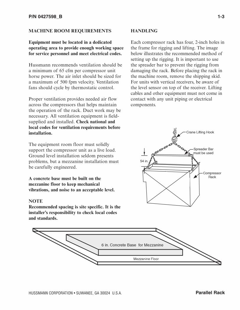
HANDLING
Each compressor rack has four, 2-inch holes inthe frame for rigging and lifting. The imagebelow illustrates the recommended method ofsetting up the rigging. It is important to usethe spreader bar to prevent the rigging fromdamaging the rack. Before placing the rack inthe machine room, remove the shipping skid.For units with vertical receivers, be aware ofthe level sensor on top of the receiver. Liftingcables and other equipment must not come incontact with any unit piping or electrical components.
54 in.
1-4 INSTALLATION
P/N 0427598_B U.S. & Canada 1-800-922-1919 • Mexico 01-800-890-2900 • WWW.HUSSMANN.COM
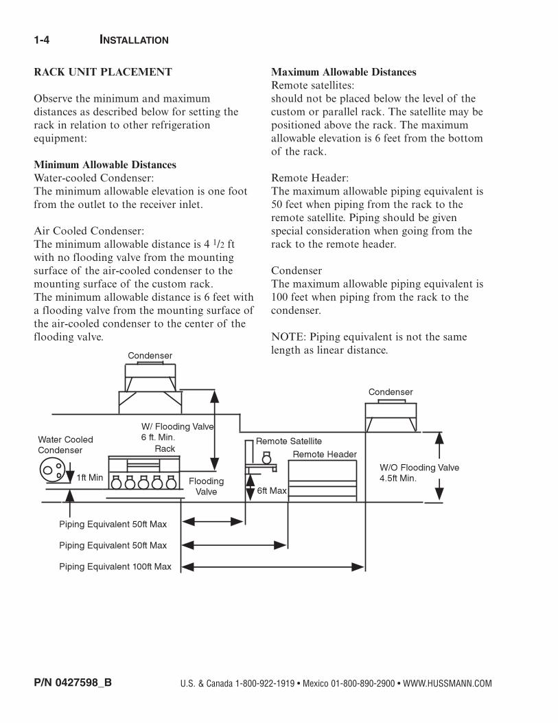
RACK UNIT PLACEMENT
Observe the minimum and maximum distances as described below for setting therack in relation to other refrigeration equipment:
Minimum Allowable DistancesWater-cooled Condenser: The minimum allowable elevation is one footfrom the outlet to the receiver inlet.
Air Cooled Condenser:The minimum allowable distance is 4 1/2 ftwith no flooding valve from the mountingsurface of the air-cooled condenser to themounting surface of the custom rack. The minimum allowable distance is 6 feet witha flooding valve from the mounting surface ofthe air-cooled condenser to the center of theflooding valve.
Maximum Allowable DistancesRemote satellites: should not be placed below the level of thecustom or parallel rack. The satellite may bepositioned above the rack. The maximumallowable elevation is 6 feet from the bottomof the rack.
Remote Header: The maximum allowable piping equivalent is50 feet when piping from the rack to theremote satellite. Piping should be given special consideration when going from therack to the remote header.
CondenserThe maximum allowable piping equivalent is100 feet when piping from the rack to thecondenser.
NOTE: Piping equivalent is not the samelength as linear distance.

Parallel Rack
P/N 0427598_B 1-5
HUSSMANN CORPORATION • SUWANEE, GA 30024 U.S.A.
VENTILATION
Cooler climates generally need less ventilationthan warmer climates. A warm machine roomis going to need a good amount of ventilation.Compressors with head fans can dissipate asmuch as 20 percent of the heat (or inputwatts). Air intake should pass over the top ofthe units where most of the heat remains. Seemachine room requirements for additionalinformation on ventilation and sizing.
FLOOR DRAIN
Provide a floor drain for disposal of conden-sate that may form on the compressor unit orheader defrost assembly.
REMOTE CONDENSER PLACEMENT
Locate the condenser with at least three feetof clearance on all sides to provide adequateair circulation if not otherwise specified bythe condenser manufacturer. If roof mounted,place on column-supported beams or load-bearing walls. The mounting surface for thecondenser should be at least six feet higherthan the rack flooding valve. When a flooding valve is not used, the minimum dis-tance from the base of the rack to the mount-ing surface of the condenser is 4.5 ft. If aKrack Microchannel (MX) is used, sufficientroom on the right side of the unit must beavailable to remove the micro channel slabs.At least nine feet of clearance must be avail-able.
Be careful when moving orlifting rack. Serious bodilyinjury or death could occurfrom falling equipment.

1-6 INSTALLATION
P/N 0427598_B U.S. & Canada 1-800-922-1919 • Mexico 01-800-890-2900 • WWW.HUSSMANN.COM
INSTALLING VIBRATION PADS
Each rack must be located in the machineroom so that it is accessible from all sides. Aminimum of 36 in. clearance is recommendedto provide easy access to components.Vibrationisolation pads are supplied with each rack. Theentire weight of the rack must rest on thesepads. The pads should be located and evenlyspaced as shown in the image below. Cross-level the compressor unit so all compressorsare level with each other. To ensure both proper leveling and vibration isolation, per-form the following:
1. Lift the rack in accordance with procedures detailed on Pages 1-3.
2. Place minimum 15 gauge 3 in. by 3 in. galvanized or stainless steel shims to compensate for uneven floors. (Shims must be field supplied.)
3. Place vibration isolation pads on top of shims. See vibration pad quantities in the table at right to determine the number of pads to be used.
# of compressorsper pack
Reciprocating or Scroll
ScrewCompressor
2 Compressors 4 Each 6 Each3 Compressors 4 Each 6 Each4 Compressors 6 Each 8 Each5 Compressors 6 Each 8 Each6 Compressors 6 Each 8 Each*7 Compressors 8 Each -----------8 Compressors 8 Each -----------9 Compressors 8 Each -----------10 Compressors 10 Each -----------
Vibration Pad Quantities3 in. x 3 in. x 2 in.
*10 for Bitzer and Vertical Receiver

Parallel Rack
P/N 0427598_B 1-7
HUSSMANN CORPORATION • SUWANEE, GA 30024 U.S.A.
# of Scroll Compressors
# of ReciprocatingCompressors
Maximum numberof circuits
Length of Rack (in.)
Approximate OperatingWeight of Rack
3 or 4 3 11 98 33305 4 15 114 42906 5 19 138 52307 6 21 150 57208 7 24 178 6270
9 or 10 8 28 200 687011 9 32 222 747012 10 36 244 8070
# of Scroll Compressors
# of ReciprocatingCompressors
Maximum numberof circuits
Length of Rack (in.)
Approximate OperatingWeight of Rack
3 or 4 3 11 128 33305 4 15 144 42906 5 19 168 52307 6 21 180 57208 7 24 208 6270
9 or 10 8 28 230 687011 9 32 252 747012 10 36 274 8070
Standard Rack Sizing Chart with Horizontal Receiver
Standard Rack Sizing Chart with Vertical Receiver
Note: Standard rack width is 39 in.Standard rack height is 78.5 in.
The charts above are acceptable for most compressor models except: screw compressors
Dimensions may vary if optional accessories such as inverters,suction accumulators, electric defrost panels, etc. are applied
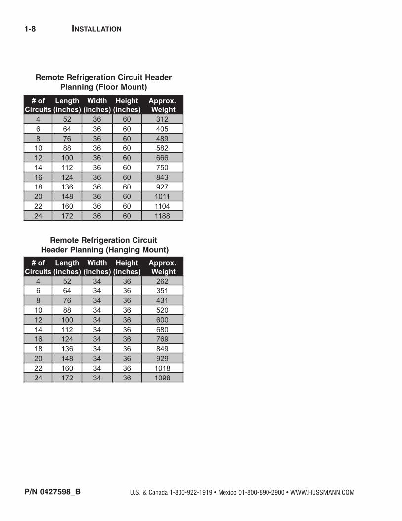
1-8 INSTALLATION
P/N 0427598_B U.S. & Canada 1-800-922-1919 • Mexico 01-800-890-2900 • WWW.HUSSMANN.COM
# ofCircuits
Length(inches)
Width(inches)
Height(inches)
Approx. Weight
4 52 36 60 3126 64 36 60 4058 76 36 60 48910 88 36 60 58212 100 36 60 66614 112 36 60 75016 124 36 60 84318 136 36 60 92720 148 36 60 101122 160 36 60 110424 172 36 60 1188
Remote Refrigeration Circuit HeaderPlanning (Floor Mount)
# ofCircuits
Length(inches)
Width(inches)
Height(inches)
Approx. Weight
4 52 34 36 2626 64 34 36 3518 76 34 36 43110 88 34 36 52012 100 34 36 60014 112 34 36 68016 124 34 36 76918 136 34 36 84920 148 34 36 92922 160 34 36 101824 172 34 36 1098
Remote Refrigeration CircuitHeader Planning (Hanging Mount)

Parallel Rack
P/N 0427598_B 2-1
RACK PIPING OVERVIEW
This section provides information for installingthe refrigeration lines for a rack. The compo-nents are piped as completely as practical at thefactory. Field piping requires only interconnec-tion of the major components and the coolers,freezers and display cases. Piping must also besupported to minimize vibration. Pulsation ofthe refrigerant and compressor vibration cancause piping to vibrate. This vibration cancause line breakage and damage to components.
Use only clean, dehydrated, sealed refrigerationgrade copper tubing. Use dry nitrogen at lowpressure in the tubing during brazing to prevent the formation of copper oxide. Alljoints should be made with a 15 percent silveralloy brazing material. Use a 45 percent silver solder for dissimilar metals.
REFRIGERATION LINE RUNS
Liquid Lines and suction lines must be free toexpand and contract independently of eachother. Do not clamp or solder them together.Supports must allow tubing to expand andcontract freely. Do not exceed 100 feet withouta change of direction or/and offset. Plan proper pitching, expansion allowance, and waterseal at the base of all suction risers. Uselong radius elbows to reduce line resistanceand breakage. Avoid the use of 45 degreeelbows. Install service valves at several locations for ease of maintenance and reduc-tion of service costs. These valves must be ULapproved for the minimum design workingpressure of the system.
Through Walls or FloorsRefrigeration lines that are run through wallsor floors must have a waterseal installed, andthe lines must be properly insulated. Avoidrunning lines through the refrigeration cases.When this is done the lines must be adequatelyinsulated using a closed-cell elastomeric foaminsulation.
HUSSMANN CORPORATION • SUWANEE, GA 30024 U.S.A.
COMPONENT PIPING & LINE SIZING
Always use a pressure regulator whenoperating nitrogen tanks.
Ceiling Run with Supports
2-2 COMPONENT PIPING & LINE SIZING
P/N 0427598_B
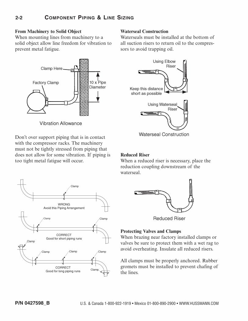
From Machinery to Solid ObjectWhen mounting lines from machinery to asolid object allow line freedom for vibration toprevent metal fatigue.
Don’t over support piping that is in contactwith the compressor racks. The machinerymust not be tightly stressed from piping thatdoes not allow for some vibration. If piping istoo tight metal fatigue will occur.
Waterseal ConstructionWaterseals must be installed at the bottom ofall suction risers to return oil to the compres-sors to avoid trapping oil.
Reduced RiserWhen a reduced riser is necessary, place thereduction coupling downstream of thewaterseal.
Protecting Valves and Clamps When brazing near factory installed clamps orvalves be sure to protect them with a wet rag toavoid overheating. Insulate all reduced risers.
All clamps must be properly anchored. Rubbergromets must be installed to prevent chafing ofthe lines.
U.S. & Canada 1-800-922-1919 • Mexico 01-800-890-2900 • WWW.HUSSMANN.COM
Parallel Rack
P/N 0427598_B 2-3
ElbowsOnly use long radius elbows. Long elbows havebeen shown to have less pressure drop andgreater strength. It is especially important touse long radius elbows to hot gas dischargelines.
Factory Supplied StubsStub sizes provided from the manifolds do notautomatically correspond to the line sizes necessary. It is the installer’s responsibility tosupply reduction couplings.
INSULATION
All suction lines and subcooled liquid lines mustbe insulated. Subcooled liquid in the liquid linewill warm if the lines are left unprotected,resulting in energy loss. Overtime this can leadto the liquid changing into a gas before it ever reaches the expansion valves. This is known asflashing. Flashing causes irregular flowthrough valves. If this occurs significant refrigerant loss and poor energy performancewill occur. Compressor motors will fail if thesuction line gas is too warm as it enters thecompressors. For gas defrost applications, insulated suction lines help maintain tempera-ture during defrost. Insulated lines also preventsweating of the lines, thus eliminating drops ofwater on the floor below the line runs.
SPECIAL PIPING FOR OPEN ROOMS
An open food preparation room allows heat infiltration from the rest of the store at a ratewhich may jeopardize total refrigeration per-formance. To protect the rest of the refrigera-tion system, open preparation evaporatorsmust be piped with a crankcase pressure regu-lating valve (CPR). The CPR is field installedin the suction line(s) from the evaporator(s).And the installer is responsible for proper
adjustment of the valve. (See: CPR ValveSection for adjustment procedures.)
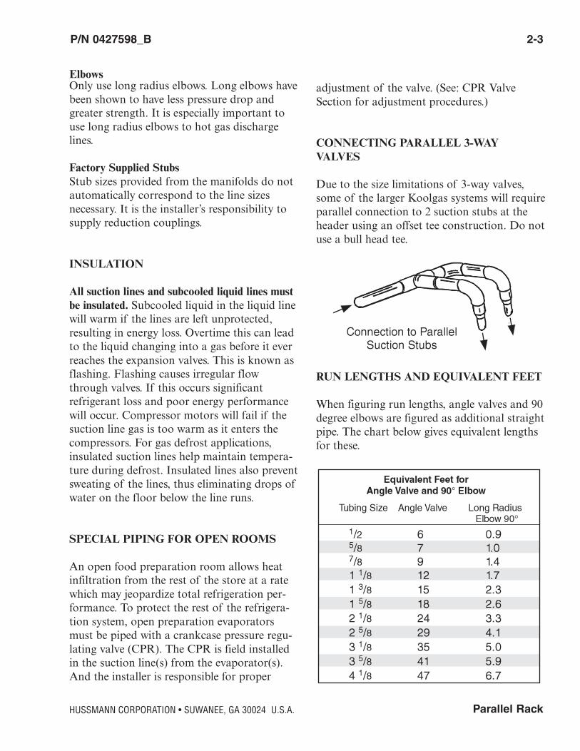
CONNECTING PARALLEL 3-WAYVALVES
Due to the size limitations of 3-way valves,some of the larger Koolgas systems will requireparallel connection to 2 suction stubs at theheader using an offset tee construction. Do notuse a bull head tee.
RUN LENGTHS AND EQUIVALENT FEET
When figuring run lengths, angle valves and 90degree elbows are figured as additional straightpipe. The chart below gives equivalent lengthsfor these.
HUSSMANN CORPORATION • SUWANEE, GA 30024 U.S.A.
2-4 COMPONENT PIPING & LINE SIZING
P/N 0427598_B U.S. & Canada 1-800-922-1919 • Mexico 01-800-890-2900 • WWW.HUSSMANN.COM
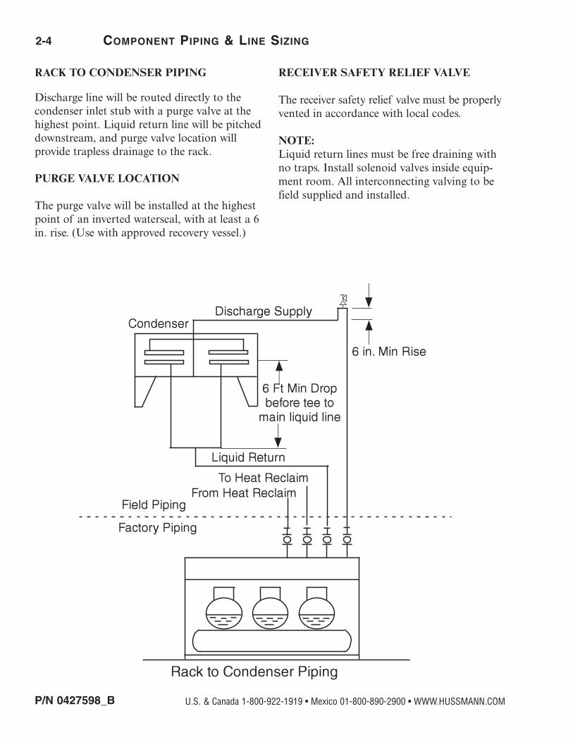
RACK TO CONDENSER PIPING
Discharge line will be routed directly to thecondenser inlet stub with a purge valve at thehighest point. Liquid return line will be pitcheddownstream, and purge valve location will provide trapless drainage to the rack.
PURGE VALVE LOCATION
The purge valve will be installed at the highestpoint of an inverted waterseal, with at least a 6in. rise. (Use with approved recovery vessel.)
RECEIVER SAFETY RELIEF VALVE
The receiver safety relief valve must be properlyvented in accordance with local codes.
NOTE: Liquid return lines must be free draining withno traps. Install solenoid valves inside equip-ment room. All interconnecting valving to befield supplied and installed.

Parallel Rack
P/N 0427598_B 2-5
CONNECTING TO TWO MANIFOLDS
The discharge line will be “tee’d” upstream ofthe manifolds into expansion offsets with atleast a one foot drop to the manifolds. Providea purge valve at the highest point. The liquidreturn lines will be “tee’d” into the main liquidreturn line after six feet of vertical drop fromthe outlet stubs. The liquid return line will bepitched downstream, and provide traplessdrainage to the rack.
EQUALIZING LINE
An equalizer line is piped between the parallelrack and the condenser. A check valve allowing flow only to the condenser and ashut off valve downstream of the check valvewill be field supplied and installed.
HUSSMANN CORPORATION • SUWANEE, GA 30024 U.S.A.

2-6 COMPONENT PIPING & LINE SIZING
P/N 0427598_B U.S. & Canada 1-800-922-1919 • Mexico 01-800-890-2900 • WWW.HUSSMANN.COM
From HeatReclaim
To HeatReclaim
Condenser
All Piping and Valves above this line are field supplied and installed
6 Ft Min Drop Before Tee to Main Liquid LineReturn
1" Min Drop After Tee from Main Discharge Line
6" MinRise
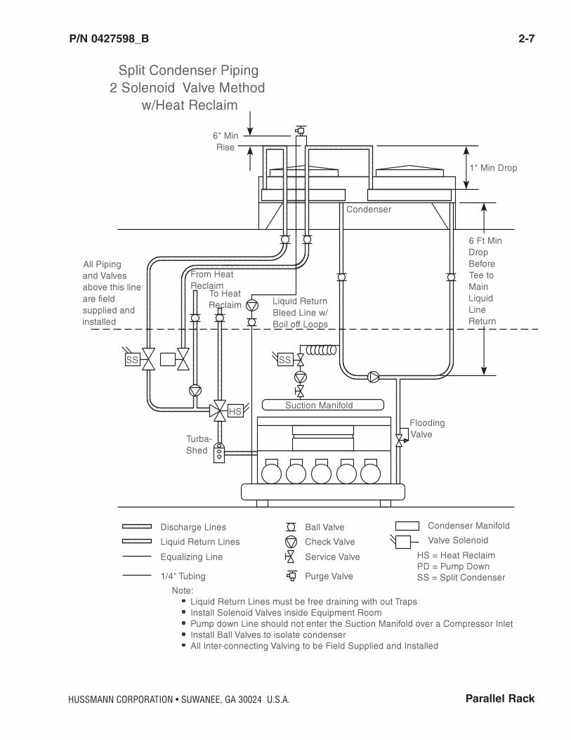
Condenser Piping w/ Heat Reclaim
Discharge LinesLiquid Return LinesEqualizing Line
Note:Liquid Return Lines must be free draining with no TrapsInstall Ball valves to isolate Condenser (Field Supplied and Installed)All Inter-connecting Valving to be Field Supplied and Installed
Ball ValveCheck ValveService Valve
Purge Valve
Condenser ManifoldValve Solenoid
HS = Heat Reclaim
HS
Oil Separator
FloodingValve
Parallel Rack
P/N 0427598_B 2-7
HUSSMANN CORPORATION • SUWANEE, GA 30024 U.S.A.

2-8 COMPONENT PIPING & LINE SIZING
P/N 0427598_B U.S. & Canada 1-800-922-1919 • Mexico 01-800-890-2900 • WWW.HUSSMANN.COM
Ft
Parallel Rack
P/N 0427598_B 2-9
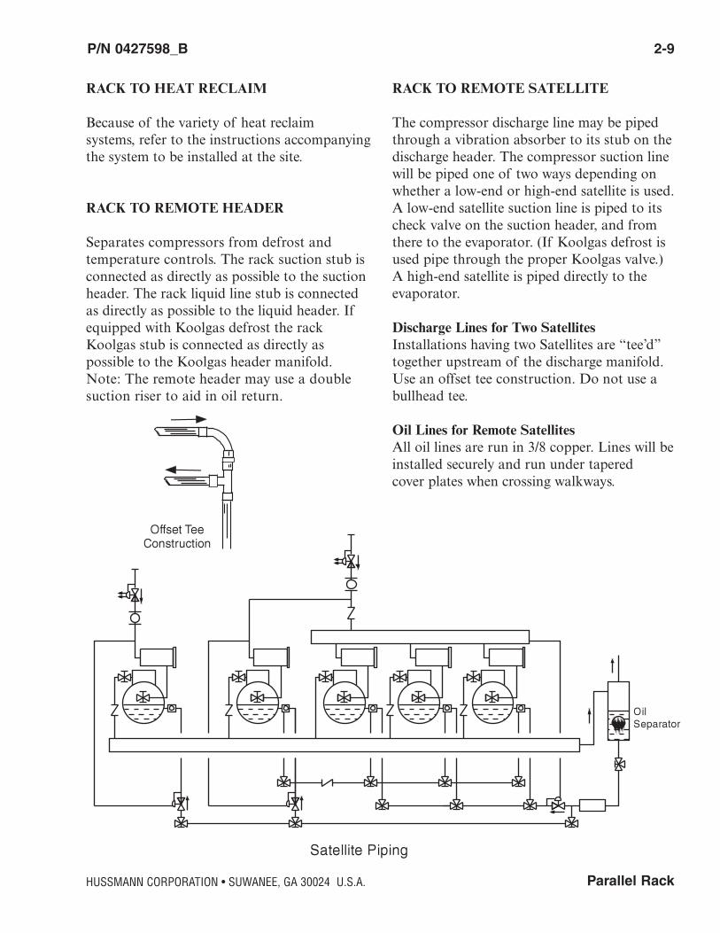
RACK TO HEAT RECLAIM
Because of the variety of heat reclaim systems, refer to the instructions accompanyingthe system to be installed at the site.
RACK TO REMOTE HEADER
Separates compressors from defrost and temperature controls. The rack suction stub isconnected as directly as possible to the suctionheader. The rack liquid line stub is connectedas directly as possible to the liquid header. Ifequipped with Koolgas defrost the rackKoolgas stub is connected as directly as possible to the Koolgas header manifold. Note: The remote header may use a doublesuction riser to aid in oil return.
RACK TO REMOTE SATELLITE
The compressor discharge line may be pipedthrough a vibration absorber to its stub on thedischarge header. The compressor suction linewill be piped one of two ways depending onwhether a low-end or high-end satellite is used.A low-end satellite suction line is piped to itscheck valve on the suction header, and fromthere to the evaporator. (If Koolgas defrost isused pipe through the proper Koolgas valve.)A high-end satellite is piped directly to theevaporator.
Discharge Lines for Two SatellitesInstallations having two Satellites are “tee’d”together upstream of the discharge manifold.Use an offset tee construction. Do not use abullhead tee.
Oil Lines for Remote Satellites All oil lines are run in 3/8 copper. Lines will beinstalled securely and run under tapered cover plates when crossing walkways.
HUSSMANN CORPORATION • SUWANEE, GA 30024 U.S.A.
2-10 COMPONENT PIPING & LINE SIZING
P/N 0427598_B U.S. & Canada 1-800-922-1919 • Mexico 01-800-890-2900 • WWW.HUSSMANN.COM
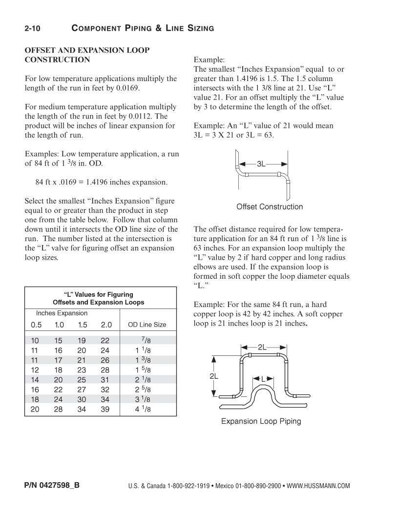
OFFSET AND EXPANSION LOOP CONSTRUCTION
For low temperature applications multiply thelength of the run in feet by 0.0169.
For medium temperature application multiplythe length of the run in feet by 0.0112. Theproduct will be inches of linear expansion forthe length of run.
Examples: Low temperature application, a runof 84 ft of 1 3/8 in. OD.
84 ft x .0169 = 1.4196 inches expansion.
Select the smallest “Inches Expansion” figureequal to or greater than the product in stepone from the table below. Follow that columndown until it intersects the OD line size of therun. The number listed at the intersection isthe “L” valve for figuring offset an expansionloop sizes.
Example: The smallest “Inches Expansion” equal to orgreater than 1.4196 is 1.5. The 1.5 columnintersects with the 1 3/8 line at 21. Use “L”value 21. For an offset multiply the “L” valueby 3 to determine the length of the offset.
Example: An “L” value of 21 would mean 3L = 3 X 21 or 3L = 63.
The offset distance required for low tempera-ture application for an 84 ft run of 1 3/8 line is63 inches. For an expansion loop multiply the“L” value by 2 if hard copper and long radiuselbows are used. If the expansion loop isformed in soft copper the loop diameter equals“L.”
Example: For the same 84 ft run, a hard copper loop is 42 by 42 inches. A soft copperloop is 21 inches loop is 21 inches.

Parallel Rack
P/N 0427598_B 2-11
HUSSMANN CORPORATION • SUWANEE, GA 30024 U.S.A.
ApplicationDo not exceed a straight run for 100 feet without constructing an offset or expansionloop. Place the offset or loop in the middle ofthe run to minimize pipe shift and joint stress.
NOTE:Sizing of all refrigerant lines is the responsibilityof the installing contractor. Contact Hussmann,Application Engineering if assistance is needed.
BRANCH LINE PIPING
Suction line Pitch in the direction of flow. Line size may bereduced by one size at one third of case runload and again after the second third. Do notreduce below evaporator connection size.Suction returns from evaporators enter at thetop of the branch line.
Liquid Line - Off-time and Electric Defrost May be reduced by one size after one halfother case load run. Do not reduce belowevaporator connection size. Take-offs to evapo-rators exit the bottom of the liquid line.Provide an expansion loop for each evaporatortake-off. (Minimum 3-inch diameter.)
2-12 COMPONENT PIPING & LINE SIZING
P/N 0427598_B U.S. & Canada 1-800-922-1919 • Mexico 01-800-890-2900 • WWW.HUSSMANN.COM
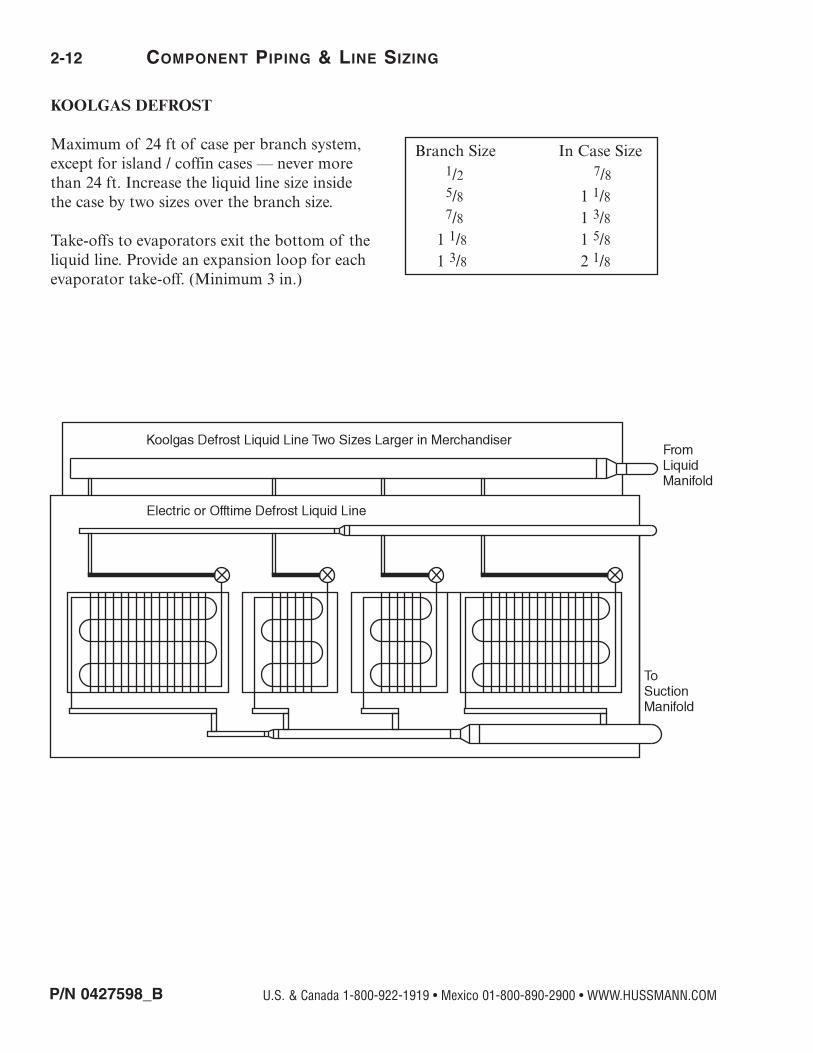
KOOLGAS DEFROST
Maximum of 24 ft of case per branch system,except for island / coffin cases — never morethan 24 ft. Increase the liquid line size insidethe case by two sizes over the branch size.
Take-offs to evaporators exit the bottom of theliquid line. Provide an expansion loop for eachevaporator take-off. (Minimum 3 in.)
Branch Size In Case Size1/2 7/85/8 1 1/87/8 1 3/81 1/8 1 5/81 3/8 2 1/8
Parallel Rack
P/N 0427598_B 2-13
HUSSMANN CORPORATION • SUWANEE, GA 30024 U.S.A.
Refrigeration Line Stub OutsStub sizes do not match line sizes. Reduction fittings are field-supplied and installed. Theseare general guidelines. The installer is responsi-ble to account for any factors which may affectthe system.
Condenser Line SizingA Condenser Line Sizing chart is established foran equivalent pipe run of 100 feet. For longerruns, use the following formula:
*Table Capacity x 100Longer Length
= Longer Line Capacity.
*NOTE: This formula applies only to remote condenserlines, and only to longer runs of these lines. A 25 ft rundoes not necessarily have double the capacity of a 100 ftrun.
Gas Defrost SystemsDo not use liquid lines smaller than 1⁄2 inch ODon any type of Gas Defrost system.
Directions and Notes
Select the MBH Value which is equal to orgreater than the MBH the line will be requiredto carry. Read the Line Size following the MBH.
MBH: values listed are always the maximum.
Vertical Riser: When the required refrigerationcapacity is less than the figure listed in the“Vertical Riser MBH” column as shown onPage 2-17, 2-19 and the riser should be the nextsize smaller. When equal to or greater than thefigure listed, the riser should be the same size asthe main tubing run.
IMPORTANT NOTES
The Hussmann Line Sizing Charts are engineered for use with Hussmann RefrigerationEquipment. Use of these charts will in no way place responsibility on Hussmann
when other than Hussmann Refrigeration Equipment is installed.
Line Sizing for other than Hussmann Refrigeration equipmentmust be provided by that manufacturer.
When other than Hussmann engineered refrigeration equipment is applied,select Case BTUH/Ft ratings from the Conventional values listed in the Merchandiser Data book.

2-14 COMPONENT PIPING & LINE SIZING
P/N 0427598_B U.S. & Canada 1-800-922-1919 • Mexico 01-800-890-2900 • WWW.HUSSMANN.COM
R-404Aand
R-507A
Medium Temperature
Condenser Line SizingCondensing Temperature °F60 70 80 90 100 110 120
Discharge LineMaximum Allowable MBH Size
39 43 46 49 52 53 54 7⁄879 86 93 98 104 107 109 1 1⁄8137 149 162 171 180 187 190 1 3⁄8217 236 255 270 284 294 299 1 5⁄8448 487 527 556 585 606 615 2 1⁄8790 859 927 981 1030 1067 1083 2 5⁄81259 1368 1474 1560 1639 1694 1719 3 1⁄8
Liquid Return LineMaximum Allowable MBH Size
70 65 59 54 49 43 37 5⁄8145 134 123 112 101 89 77 7⁄8247 229 210 191 172 152 132 1 1⁄8376 349 320 291 262 232 201 1 3⁄8533 493 453 412 371 328 284 1 5⁄8927 858 788 717 645 571 494 2 1⁄81429 1324 1215 1106 994 880 762 2 5⁄82040 1889 1735 1578 1419 1256 1088 3 1⁄8
Remote Header Line SizingMaximum MaximumAllowable Liquid Allowable SuctionMBH Main MBH Main
203 1 1⁄8 159 1 5⁄8309 1 3⁄8 277 2 1⁄8437 1 5⁄8 427 2 5⁄8761 2 1⁄8 609 3 1⁄81173 2 5⁄8 824 3 5⁄8
1071 4 1⁄8
Liquid Supply Line Sizing Cond Maximum MBH of Refrigeration Tubing Temp per Length of Equivalent Feet Size°F OD
50 100 150 200 250 300
80 25 17 14 12 10 9 3⁄858 40 32 27 24 21 1⁄299 75 60 51 45 41 5⁄8205 197 158 135 119 108 7⁄8350 350 321 274 242 219 1 1⁄8533 533 533 478 424 384 1 3⁄8755 755 755 755 672 609 1 5⁄81313 1313 1313 1313 1313 1266 2 1⁄82025 2025 2025 2025 2025 2025 2 5⁄8
90 25 17 13 11 10 9 3⁄856 39 31 26 23 21 1⁄290 73 59 50 44 40 5⁄8187 187 155 132 117 106 7⁄8319 319 314 269 238 215 1 1⁄8485 485 485 470 416 377 1 3⁄8687 687 687 687 659 597 1 5⁄81195 1195 1195 1195 1195 1195 2 1⁄81843 1843 1843 1843 1843 1843 2 5⁄8
100 24 16 13 11 10 9 3⁄850 38 30 26 23 21 1⁄281 71 57 49 43 39 5⁄8168 168 150 129 114 103 7⁄8286 286 286 261 231 209 1 1⁄8436 436 436 436 403 365 1 3⁄8618 618 618 618 618 580 1 5⁄81074 1074 1074 1074 1074 1074 2 1⁄81657 1657 1657 1657 1657 1657 2 5⁄8
110 23 16 13 11 9 9 3⁄845 36 29 25 22 20 1⁄272 68 54 46 41 37 5⁄8149 149 144 123 109 98 7⁄8254 254 254 249 221 200 1 1⁄8386 386 386 386 386 349 1 3⁄8547 547 547 547 547 547 1 5⁄8951 951 951 951 951 951 2 1⁄81466 1466 1466 1466 1466 1466 2 5⁄8
120 21 15 12 10 9 8 3⁄839 34 27 23 21 19 1⁄262 62 51 44 39 35 5⁄8129 129 129 116 102 93 7⁄8220 220 220 220 208 188 1 1⁄8334 334 334 334 334 329 1 3⁄8473 473 473 473 473 473 1 5⁄8824 824 824 824 824 824 2 1⁄81270 1270 1270 1270 1270 1270 2 5⁄8
Parallel Rack
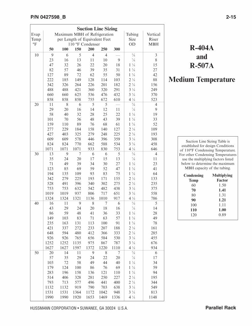
P/N 0427598_B 2-15
HUSSMANN CORPORATION • SUWANEE, GA 30024 U.S.A.
R-404Aand
R-507A
Medium Temperature
Suction Line SizingEvap Maximum MBH of Refrigeration Tubing VerticalTemp per Length of Equivalent Feet Size Riser°F 110 °F Condenser OD MBH
50 100 150 200 250 30010 9 6 5 4 4 — 5⁄8 3
23 16 13 11 10 9 7⁄8 847 32 26 22 20 18 1 1⁄8 1582 57 46 39 35 31 1 3⁄8 27127 89 72 62 55 50 1 5⁄8 42222 185 149 128 114 103 2 1⁄8 88342 326 264 226 201 182 2 5⁄8 156488 488 421 360 320 291 3 1⁄8 249660 660 625 536 476 432 3 5⁄8 370858 858 858 755 672 610 4 1⁄8 523
20 11 8 6 5 5 — 5⁄8 429 20 16 14 12 11 7⁄8 958 40 32 28 25 22 1 1⁄8 19101 70 56 48 43 39 1 3⁄8 33159 110 89 76 68 61 1 5⁄8 52277 229 184 158 140 127 2 1⁄8 109427 403 325 279 248 225 2 5⁄8 193609 609 578 446 396 359 3 1⁄8 308824 824 770 662 588 534 3 5⁄8 4581071 1071 1071 933 830 753 4 1⁄8 646
30 13 9 7 6 6 5 5⁄8 435 24 20 17 15 13 7⁄8 1171 49 39 34 30 27 1 1⁄8 23123 85 69 59 52 47 1 3⁄8 41194 135 109 93 83 75 1 5⁄8 64342 279 225 193 171 155 2 1⁄8 133528 491 396 340 302 275 2 5⁄8 235753 753 632 542 482 438 3 1⁄8 3751019 1019 937 806 717 651 3 5⁄8 5581324 1324 1321 1136 1010 917 4 1⁄8 786
40 16 11 9 8 7 6 5⁄8 543 29 24 20 18 16 7⁄8 1486 59 48 41 36 33 1 1⁄8 28149 103 83 71 63 57 1 3⁄8 49235 163 131 113 100 91 1 5⁄8 78421 337 272 233 207 188 2 1⁄8 161648 594 480 412 366 333 2 5⁄8 285926 926 765 656 584 530 3 1⁄8 4551252 1252 1135 975 867 787 3 5⁄8 6761627 1627 1597 1372 1220 1110 4 1⁄8 934
50 20 14 11 9 8 7 5⁄8 657 35 29 24 22 20 7⁄8 17103 72 58 49 44 40 1 1⁄8 34179 124 100 86 76 69 1 3⁄8 59283 196 158 136 121 110 1 5⁄8 94514 406 328 281 250 227 2 1⁄8 195793 713 577 496 441 400 2 5⁄8 3441132 1132 919 790 703 638 3 1⁄8 5491531 1531 1364 1172 1042 948 3 5⁄8 8131990 1990 1920 1653 1469 1336 4 1⁄8 1148
Suction Line Sizing Table is established for design Conditions of 110°F Condensing Temperature.For other Condensing Temperaturesuse the multiplying factors listedbelow to determine the maximumMBH capacity of the tubing.
CondensingTemp60708090100110120
MultiplyingFactor1.501.411.311.211.111.000.89

2-16 COMPONENT PIPING & LINE SIZING
P/N 0427598_B U.S. & Canada 1-800-922-1919 • Mexico 01-800-890-2900 • WWW.HUSSMANN.COM
R-404Aand
R-507A
Low Temperature
Condenser Line SizingCondensing Temperature °F60 70 80 90 100 105 110 120
Discharge LineMaximum Allowable MBH Size
35 38 41 43 45 45 46 48 7⁄871 77 83 87 90 91 92 96 1 1⁄8124 134 144 151 157 158 160 167 1 3⁄8196 212 227 238 247 250 252 263 1 5⁄8405 438 469 491 510 515 520 541 2 1⁄8715 772 826 865 898 905 915 953 2 5⁄81139 1229 1313 1376 1428 1439 1453 1513 3 1⁄8
Liquid Return LineMaximum Allowable MBH Size
71 66 61 56 50 47 44 39 5⁄8148 137 126 115 104 98 92 80 7⁄8253 234 216 196 177 167 157 136 1 1⁄8385 357 328 299 269 254 239 208 1 3⁄8545 505 465 424 381 360 339 294 1 5⁄8948 879 808 737 664 626 589 512 2 1⁄81462 1356 1246 1136 1023 965 908 789 2 5⁄82086 1935 1779 1622 1461 1378 1296 1126 3 1⁄8
Remote Header Line SizingMaximum MaximumAllowable Liquid Allowable SuctionMBH Main MBH Main
223 1 1⁄8 66 1 5⁄8339 1 3⁄8 115 2 1⁄8480 1 5⁄8 177 2 5⁄8835 2 1⁄8 252 3 1⁄81287 2 5⁄8 341 3 5⁄81837 3 1⁄8 443 4 1⁄8
690 5 1⁄8
Liquid Supply Line Sizing Cond Maximum MBH of Refrigeration Tubing Temp per Length of Equivalent Feet Size°F OD
50 100 150 200 250 300
80 26 18 14 12 11 10 3⁄859 41 32 28 24 22 1⁄2102 77 61 52 46 42 5⁄8211 202 162 138 122 111 7⁄8359 359 329 281 249 225 1 1⁄8547 547 547 491 435 393 1 3⁄8774 774 774 774 689 624 1 5⁄81347 1347 1347 1347 1347 1298 2 1⁄82077 2077 2077 2077 2077 2077 2 5⁄8
90 25 17 14 12 10 9 3⁄858 40 32 27 24 22 1⁄293 75 60 51 45 41 5⁄8192 192 159 136 120 109 7⁄8327 327 323 276 244 221 1 1⁄8499 499 499 483 427 387 1 3⁄8706 706 706 706 677 613 1 5⁄81228 1228 1228 1228 1228 1228 2 1⁄81894 1894 1894 1894 1894 1894 2 5⁄8
100 25 17 14 12 10 9 3⁄848 39 32 27 24 22 1⁄277 73 60 51 45 41 5⁄8159 159 157 135 119 108 7⁄8271 271 271 271 242 219 1 1⁄8413 413 413 413 413 382 1 3⁄8585 585 585 585 585 585 1 5⁄81018 1018 1018 1018 1018 1018 2 1⁄81569 1569 1569 1569 1569 1569 2 5⁄8
110 24 16 13 11 10 9 3⁄846 37 30 25 22 20 1⁄274 70 56 48 42 38 5⁄8153 153 148 127 112 101 7⁄8262 262 262 257 228 206 1 1⁄8399 399 399 399 399 360 1 3⁄8564 564 564 564 564 564 1 5⁄8981 981 981 981 981 981 2 1⁄81513 1513 1513 1513 1513 1513 2 5⁄8
120 21 15 12 10 9 8 3⁄840 35 28 24 21 19 1⁄264 64 53 45 40 36 5⁄8133 133 133 120 106 61 7⁄8227 227 227 227 215 195 1 1⁄8346 346 346 346 346 340 1 3⁄8490 490 490 490 490 490 1 5⁄8853 853 853 853 853 853 2 1⁄81315 1315 1315 1315 1315 1315 2 5⁄8

Parallel Rack
P/N 0427598_B 2-17
HUSSMANN CORPORATION • SUWANEE, GA 30024 U.S.A.
R-404Aand
R-507A
Low Temperature
Suction Line Sizing Table is estab-lished for design Conditions of105°F Condensing Temperature. Forother Condensing Temperatures usethe multiplying factors listed belowto determine the maximum MBHcapacity of the tubing.
CondensingTemp60708090100110120
MultiplyingFactor1.491.391.281.171.060.940.81
Suction Line SizingEvap Maximum MBH of Refrigeration Tubing VerticalTemp per Length of Equivalent Feet Size Riser°F 105 °F Condenser OD MBH
50 100 150 200 250 300–40 7 5 4 3 3 3 7⁄8 2
15 10 8 7 6 5 1 1⁄8 526 18 14 12 11 10 1 3⁄8 838 28 22 19 17 15 1 5⁄8 1367 58 46 40 35 32 2 1⁄8 27103 103 82 71 62 57 2 5⁄8 48140 140 132 113 100 91 3 1⁄8 77199 199 196 168 149 135 3 5⁄8 115259 259 259 237 211 191 4 1⁄8 163403 403 403 403 377 342 5 1⁄8 294
–30 9 6 5 4 4 4 7⁄8 319 13 11 9 8 7 1 1⁄8 634 23 18 16 14 13 1 3⁄8 1150 36 29 25 22 20 1 5⁄8 1788 76 61 52 46 42 2 1⁄8 36136 134 108 92 82 74 2 5⁄8 69194 194 172 148 131 119 3 1⁄8 101262 262 256 219 195 177 3 5⁄8 151340 340 340 310 275 249 4 1⁄8 213530 530 530 530 493 446 5 1⁄8 383
–20 12 8 7 6 5 5 7⁄8 425 17 14 12 10 9 1 1⁄8 843 30 24 20 18 16 1 3⁄8 1466 47 38 32 29 26 1 5⁄8 22115 98 79 67 60 54 2 1⁄8 46177 173 139 119 106 96 2 5⁄8 82252 252 222 190 169 153 3 1⁄8 131341 341 330 283 251 227 3 5⁄8 195443 443 443 399 354 322 4 1⁄8 275690 690 690 690 634 576 5 1⁄8 493
–10 16 11 9 7 6 6 7⁄8 532 22 17 15 13 12 1 1⁄8 1055 38 30 26 23 21 1 3⁄8 1884 60 48 41 37 33 1 5⁄8 28147 125 100 86 76 69 2 1⁄8 59226 220 177 152 134 122 2 5⁄8 104323 323 283 242 215 195 3 1⁄8 167437 437 420 360 320 290 3 5⁄8 248568 568 568 508 451 410 4 1⁄8 351886 886 886 886 807 733 5 1⁄8 629
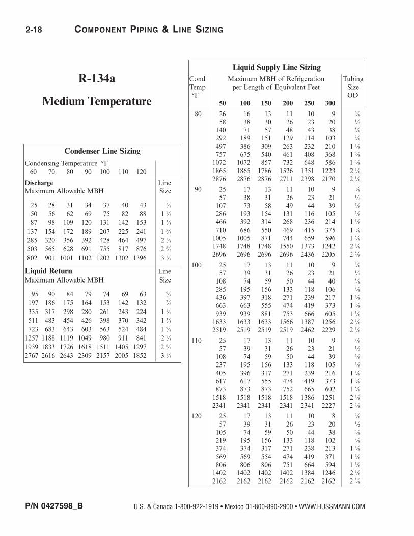
R-134a
Medium Temperature
Liquid Supply Line Sizing Cond Maximum MBH of Refrigeration Tubing Temp per Length of Equivalent Feet Size°F OD
50 100 150 200 250 300
80 26 16 13 11 10 9 3⁄858 38 30 26 23 20 1⁄2140 71 57 48 43 38 5⁄8292 189 151 129 114 103 7⁄8497 386 309 263 232 210 1 1⁄8757 675 540 461 408 368 1 3⁄81072 1072 857 732 648 586 1 5⁄81865 1865 1786 1526 1351 1223 2 1⁄82876 2876 2876 2711 2398 2170 2 5⁄8
90 25 17 13 11 10 9 3⁄857 38 31 26 23 21 1⁄2107 73 58 49 44 39 5⁄8286 193 154 131 116 105 7⁄8466 392 314 268 236 214 1 1⁄8710 686 550 469 415 375 1 3⁄81005 1005 871 744 659 596 1 5⁄81748 1748 1748 1550 1373 1242 2 1⁄82696 2696 2696 2696 2436 2205 2 5⁄8
100 25 17 13 11 10 9 3⁄857 39 31 26 23 21 1⁄2108 74 59 50 44 40 5⁄8285 195 156 133 118 106 7⁄8436 397 318 271 239 217 1 1⁄8663 663 555 474 419 373 1 3⁄8939 939 881 753 666 605 1 5⁄81633 1633 1633 1566 1387 1256 2 1⁄82519 2519 2519 2519 2462 2229 2 5⁄8
110 25 17 13 11 10 9 3⁄857 39 31 26 23 21 1⁄2108 74 59 50 44 39 5⁄8237 195 156 133 118 105 7⁄8405 396 317 271 239 216 1 1⁄8617 617 555 474 419 373 1 3⁄8873 873 873 752 665 602 1 5⁄81518 1518 1518 1518 1386 1251 2 1⁄82341 2341 2341 2341 2341 2227 2 5⁄8
120 25 17 13 11 10 8 3⁄857 39 31 26 23 20 1⁄2105 74 59 50 44 38 5⁄8219 195 156 133 118 102 7⁄8374 374 317 271 238 213 1 1⁄8569 569 554 474 419 371 1 3⁄8806 806 806 751 664 594 1 5⁄81402 1402 1402 1402 1384 1246 2 1⁄82162 2162 2162 2162 2162 2162 2 5⁄8
Condenser Line SizingCondensing Temperature °F60 70 80 90 100 110 120
Discharge LineMaximum Allowable MBH Size
25 28 31 34 37 40 43 7⁄850 56 62 69 75 82 88 1 1⁄887 98 109 120 131 142 153 1 3⁄8137 154 172 189 207 225 241 1 5⁄8285 320 356 392 428 464 497 2 1⁄8503 565 628 691 755 817 876 2 5⁄8802 901 1001 1102 1202 1302 1396 3 1⁄8
Liquid Return LineMaximum Allowable MBH Size
95 90 84 79 74 69 63 5⁄8197 186 175 164 153 142 132 7⁄8335 317 298 280 261 243 224 1 1⁄8511 483 454 426 398 370 342 1 3⁄8723 683 643 603 563 524 484 1 5⁄81257 1188 1119 1049 980 911 841 2 1⁄81939 1833 1726 1618 1511 1405 1297 2 5⁄82767 2616 2643 2309 2157 2005 1852 3 1⁄8
U.S. & Canada 1-800-922-1919 • Mexico 01-800-890-2900 • WWW.HUSSMANN.COMP/N 0427598_B
2-18 COMPONENT PIPING & LINE SIZING
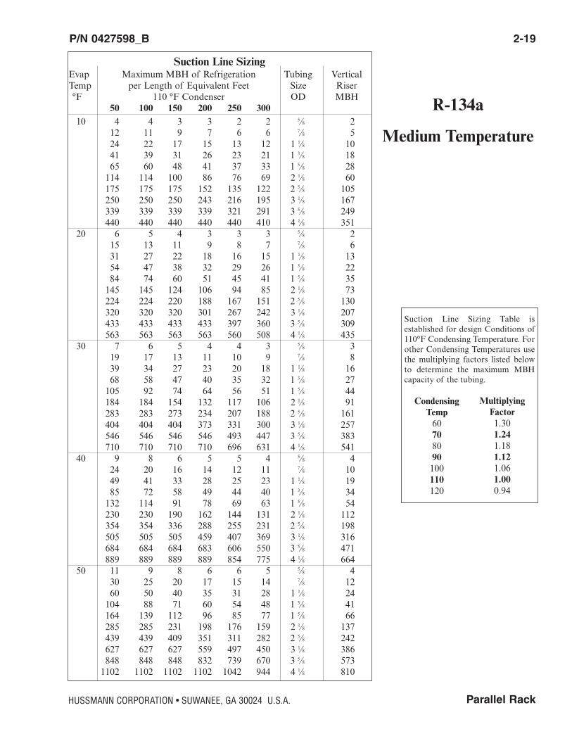
R-134a
Medium Temperature
Suction Line Sizing Table is established for design Conditions of110°F Condensing Temperature. Forother Condensing Temperatures usethe multiplying factors listed belowto determine the maximum MBH capacity of the tubing.
CondensingTemp60708090100110120
MultiplyingFactor1.301.241.181.121.061.000.94
Suction Line SizingEvap Maximum MBH of Refrigeration Tubing VerticalTemp per Length of Equivalent Feet Size Riser°F 110 °F Condenser OD MBH
50 100 150 200 250 30010 4 4 3 3 2 2 5⁄8 2
12 11 9 7 6 6 7⁄8 524 22 17 15 13 12 1 1⁄8 1041 39 31 26 23 21 1 3⁄8 1865 60 48 41 37 33 1 5⁄8 28114 114 100 86 76 69 2 1⁄8 60175 175 175 152 135 122 2 5⁄8 105250 250 250 243 216 195 3 1⁄8 167339 339 339 339 321 291 3 5⁄8 249440 440 440 440 440 410 4 1⁄8 351
20 6 5 4 3 3 3 5⁄8 215 13 11 9 8 7 7⁄8 631 27 22 18 16 15 1 1⁄8 1354 47 38 32 29 26 1 3⁄8 2284 74 60 51 45 41 1 5⁄8 35145 145 124 106 94 85 2 1⁄8 73224 224 220 188 167 151 2 5⁄8 130320 320 320 301 267 242 3 1⁄8 207433 433 433 433 397 360 3 5⁄8 309563 563 563 563 560 508 4 1⁄8 435
30 7 6 5 4 4 3 5⁄8 319 17 13 11 10 9 7⁄8 839 34 27 23 20 18 1 1⁄8 1668 58 47 40 35 32 1 3⁄8 27105 92 74 64 56 51 1 5⁄8 44184 184 154 132 117 106 2 1⁄8 91283 283 273 234 207 188 2 5⁄8 161404 404 404 373 331 300 3 1⁄8 257546 546 546 546 493 447 3 5⁄8 383710 710 710 710 696 631 4 1⁄8 541
40 9 8 6 5 5 4 5⁄8 424 20 16 14 12 11 7⁄8 1049 41 33 28 25 23 1 1⁄8 1985 72 58 49 44 40 1 3⁄8 34132 114 91 78 69 63 1 5⁄8 54230 230 190 162 144 131 2 1⁄8 112354 354 336 288 255 231 2 5⁄8 198505 505 505 459 407 369 3 1⁄8 316684 684 684 683 606 550 3 5⁄8 471889 889 889 889 854 775 4 1⁄8 664
50 11 9 8 6 6 5 5⁄8 430 25 20 17 15 14 7⁄8 1260 50 40 35 31 28 1 1⁄8 24104 88 71 60 54 48 1 3⁄8 41164 139 112 96 85 77 1 5⁄8 66285 285 231 198 176 159 2 1⁄8 137439 439 409 351 311 282 2 5⁄8 242627 627 627 559 497 450 3 1⁄8 386848 848 848 832 739 670 3 5⁄8 5731102 1102 1102 1102 1042 944 4 1⁄8 810
P/N 0427598_B 2-19
Parallel RackHUSSMANN CORPORATION • SUWANEE, GA 30024 U.S.A.

2-20 COMPONENT PIPING & LINE SIZING
P/N 0427598_B
NOTES:
U.S. & Canada 1-800-922-1919 • Mexico 01-800-890-2900 • WWW.HUSSMANN.COM
Parallel Rack
P/N 0427598_B 3-1
HUSSMANN CORPORATION • SUWANEE, GA 30024 U.S.A.
OVERVIEW
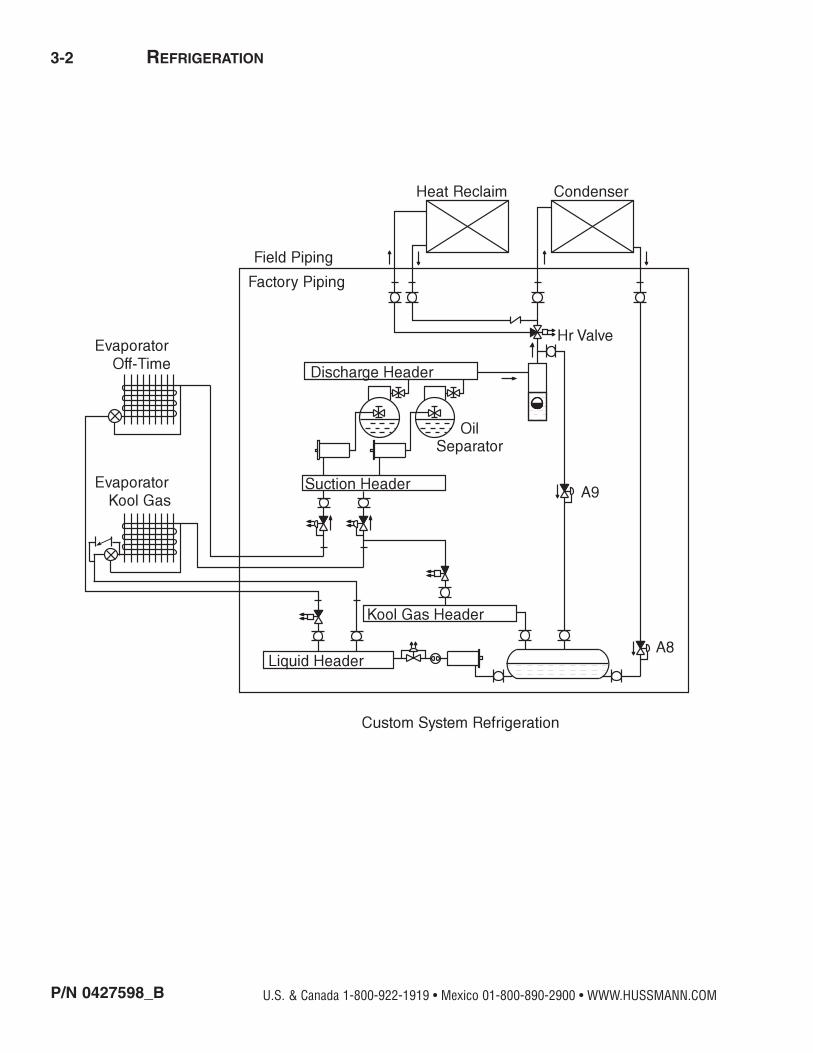
This section details the refrigeration processby tracking the refrigerant flow through therack components. Oil separation and returnis explained as well.
The rack is designed with an adequately-sizedreceiver for proper refrigerant management.The compact design reduces height and widthrequirements as well as providing convenientaccess to components for easy maintenanceand service. In the diagrams refrigerant flowdirection is generally clockwise and indicatedby directional arrows. Electrical solenoidvalves carry the same initial abbreviations asin the electrical schematics.
Refrigeration lines not actually in the cyclebeing discussed are shown closed or removed.Pressure oil lines will retain a fixed pattern.
BASIC REFRIGERATION CYCLE
Beginning with the parallel compressors,refrigerant vapor is compressed and flows tothe oil separator and returned to the compressors. A 3-way valve directs the super-heated discharge gas to either the condenseror a heat reclaim device when energized.When the reclaim solenoid is de-energized thevalve directs the refrigerant to the condenser.The condenser rejects the heat that must beremoved from the refrigerant to cause it tocondense.
The flooding valve maintains head pressurein low ambient conditions by restricting liq-uid refrigerant flow from the condenser.
This causes liquid refrigerant flow to bebacked up in the condenser, thus reducingavailable heat transfer surface and causingthe discharge pressure to rise. The receiver isa holding vessel for liquid refrigerant. Thereceiver compensates for fluctuations in liq-uid requirements during changing loads,defrosts and weather.
The main liquid pressure differential valvefunctions during gas defrost to reduce pres-sure to the liquid header. The reduced pressure allows reverse flow of refrigerant gasthrough the evaporator necessary for aneffective defrost.
The liquid header distributes liquid refrigerant to all branch liquid lines. Thebranch liquid line solenoid valve closes offrefrigerant supply to the evaporator. Thevalve also allows back flow of refrigerantinto the liquid header.
REFRIGERATION
Oil Separator
Flooding Valve
It is the installing contractor’s responsibility to consult local agencies
for local code requirements.
3-2 REFRIGERATION
P/N 0427598_B U.S. & Canada 1-800-922-1919 • Mexico 01-800-890-2900 • WWW.HUSSMANN.COM
Parallel Rack
P/N 0427598_ B 3-3
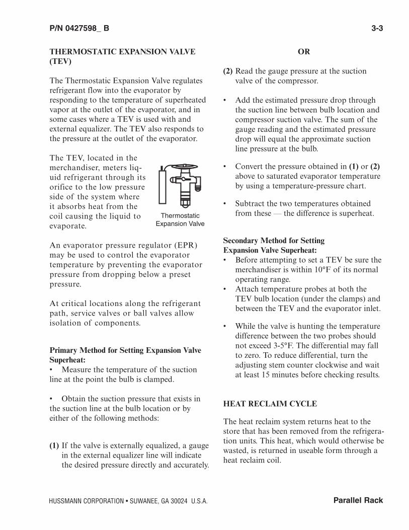
THERMOSTATIC EXPANSION VALVE(TEV)
The Thermostatic Expansion Valve regulatesrefrigerant flow into the evaporator byresponding to the temperature of superheatedvapor at the outlet of the evaporator, and insome cases where a TEV is used with andexternal equalizer. The TEV also responds tothe pressure at the outlet of the evaporator.
The TEV, located in themerchandiser, meters liq-uid refrigerant through itsorifice to the low pressureside of the system whereit absorbs heat from thecoil causing the liquid toevaporate.
An evaporator pressure regulator (EPR)may be used to control the evaporator temperature by preventing the evaporatorpressure from dropping below a preset pressure.
At critical locations along the refrigerantpath, service valves or ball valves allow isolation of components.
Primary Method for Setting Expansion ValveSuperheat:• Measure the temperature of the suctionline at the point the bulb is clamped.
• Obtain the suction pressure that exists inthe suction line at the bulb location or byeither of the following methods:
(1) If the valve is externally equalized, a gauge in the external equalizer line will indicate the desired pressure directly and accurately.
OR
(2) Read the gauge pressure at the suction valve of the compressor.
• Add the estimated pressure drop through the suction line between bulb location and compressor suction valve. The sum of the gauge reading and the estimated pressure drop will equal the approximate suction line pressure at the bulb.
• Convert the pressure obtained in (1) or (2)above to saturated evaporator temperature by using a temperature-pressure chart.
• Subtract the two temperatures obtained from these — the difference is superheat.
Secondary Method for Setting Expansion Valve Superheat:• Before attempting to set a TEV be sure the
merchandiser is within 10°F of its normal operating range.
• Attach temperature probes at both the TEV bulb location (under the clamps) and between the TEV and the evaporator inlet.
• While the valve is hunting the temperature difference between the two probes should not exceed 3-5°F. The differential may fall to zero. To reduce differential, turn the adjusting stem counter clockwise and wait at least 15 minutes before checking results.
HEAT RECLAIM CYCLE
The heat reclaim system returns heat to thestore that has been removed from the refrigera-tion units. This heat, which would otherwise bewasted, is returned in useable form through aheat reclaim coil.
HUSSMANN CORPORATION • SUWANEE, GA 30024 U.S.A.
ThermostaticExpansion Valve
3-4 REFRIGERATION
P/N 0427598_B U.S. & Canada 1-800-922-1919 • Mexico 01-800-890-2900 • WWW.HUSSMANN.COM
The heat reclaim 3-way valve energizes duringreclaim mode diverting discharge gas to aremote mounted air reclaim coil or water heating coil or other heat exchanger. After thedischarge gas passes through the reclaim coil,it returns to the system through a check valveand then to the condenser. The check valveassures no back flow and flooding when heatreclaim cycle is off. During heat reclaim, theheat reclaim coil rejects superheat from therefrigerant vapor and the condenser coil rejectslatent heat and produces quality liquid for therefrigeration process. The heat reclaim coilshould not be oversized.
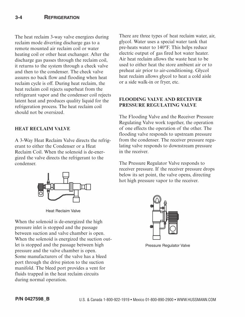
HEAT RECLAIM VALVE
A 3-Way Heat Reclaim Valve directs the refrig-erant to either the Condenser or a HeatReclaim Coil. When the solenoid is de-ener-gized the valve directs the refrigerant to thecondenser.
When the solenoid is de-energized the highpressure inlet is stopped and the passagebetween suction and valve chamber is open.When the solenoid is energized the suction out-let is stopped and the passage between highpressure and the valve chamber is open. Some manufacturers of the valve has a bleedport through the drive piston to the suctionmanifold. The bleed port provides a vent forfluids trapped in the heat reclaim circuits during normal operation.
There are three types of heat reclaim water, air,glycol. Water uses a special water tank thatpre-heats water to 140°F. This helps reduceelectric output of gas fired hot water heater.Air heat reclaim allows the waste heat to beused to either heat the store ambient air or topreheat air prior to air-conditioning. Glycolheat reclaim allows glycol to heat a cold aisleor a side walk-in or fryer, etc.
FLOODING VALVE AND RECEIVERPRESSURE REGULATING VALVE
The Flooding Valve and the Receiver PressureRegulating Valve work together, the operationof one effects the operation of the other. Theflooding valve responds to upstream pressurefrom the condenser. The receiver pressure regu-lating valve responds to downstream pressurein the receiver.
The Pressure Regulator Valve responds toreceiver pressure. If the receiver pressure dropsbelow its set point, the valve opens, directinghot high pressure vapor to the receiver.
Heat Reclaim Valve
Pressure Regulator Valve

Parallel Rack
P/N 0427598_B 3-5
The Flooding Valve maintains head pressure in low ambient conditions by reducing theavailable condensing area. Restricting liquidrefrigerant flow from the condenser, the flooding valve prevents the liquid refrigerantfrom leaving the condenser as fast as it is forming, so the condenser floods with its owncondensate.
KOOLGAS DEFROST CYCLE
Beginning with the receiver the Koolgas cyclesplits in two directions – receiver vapor andreceiver liquid. The high pressure liquid flowingfrom the receiver is throttled by the main liquidline solenoid valve causing a pressure reductionin the liquid header.
If a branch liquid line solenoid valve is used ona Koolgas circuit, the liquid circuit is designedto allow backflow into the reduced pressure liq-uid header by an external parallel check valveor by a special solenoid valve designed to allowreverse flow. When a branch of refrigerationcases enters the defrost cycle its branch valveallows refrigerant to flow into the liquid header.
The receiver vapor flows directly into theKoolgas header. This Koolgas Vapor maintainsthe same high pressure as the receiver. A 3-way valve closes the suction line to the suction header and opens the Koolgas line tothe evaporator. Koolgas vapor flows backwardthrough the evaporator, giving up heat to theevaporator for defrost.
The Koolgas vapor condenses and flows intothe reduced pressure liquid line through aBypass check valve around the TEV. Fromthere it is returned to the liquid line header. If a suction stop or EPR with suction stop isused to control evaporator temperature, the 3-way valve is not used.
When defrost is called for, the suction line con-trol valve closes and a two-way Koolgas valvesopens the line from the Koolgas header to theevaporator.
OIL SYSTEM
Discharge refrigerant carries droplets of oilfrom the compressors’ lubrication system. TheTurba-shed or other oil separator returns theoil from its reservoir along a high pressure lineto the oil pressure differential regulator valve.This valve reduces the oil pressure to between20 and 25 psig above the crankcase pressure ofthe compressor, providing even flow of oil tothe oil level regulators or floats.
To balance oil level among the compressors anequalizing line returns any excess oil in one oillevel regulator to the rest of the system. Acheck valve is placed in the equalizing linebetween the low end satellite and the rest of thesystem. The check valve is necessary to keepthe low end satellite from filling up with oil.With a high end satellite, note that the satellitehas no equalizing line.
Regulation Valve The special oil pressure differential valve isused to reduce the high pressure in the combination oil separator and reservoir to apressure slightly above the suction pressure toprevent overfeeding of the compressor float.The valve has an adjustment range of 3 to 30psi differential pressure. Typically, this pressureshould be approximately 20 to 25 psig abovethe suction pressure.
HUSSMANN CORPORATION • SUWANEE, GA 30024 U.S.A.
3-6 REFRIGERATION
P/N 0427598_B
NOTE: Every suction group or satellite com-pressor should has its own pressure differentialvalve.
Adjustments are made at the bottom of thevalve. To adjust, remove the valve cap andturn the stem with a valve wrench. To increasethe differential, screw the stem in; to decreasethe differential, screw the stem out. One turngives 4 psi of adjustment.
NOTE: An increase in differential means higher oil pressure into the floats.
Oil Level Regulators For any brand of oil level regulator to workaccurately the unit and each compressor mustbe level. Both Sporlan and AC & R regulatorsmay be damaged by over adjusting. Do notexceed 175 psig when testing to prevent damage to the floats. A sightglass filled withoil may indicate a damaged regulator. Before beginning adjusting, isolate the com-pressor by turning off its control circuit. Sporlan Oil Level Control OL-1 Series
The Sporlan Oil Level Regulator comes presetto maintain oil level at the center line of thesightglass. If there is any question as to theactual set point of the regulator, turn theadjustment stem counterclockwise until the topstop is reached. Then adjust the oil level downto the desired height by turning the stem clockwise. Each full turn will represent about.05 inches change in oil level. Do not exceednine turns from the top, or the control may bedamaged.
Y825 VALVE ADJUSTMENT
1) Close all the oil float service valves. This is done by turning the valve stem in the clock wise direction until they bottom out.
2) Connect a low pressure gauge to the suction header.
3) Connect the low side gauge hose of a gaugemanifold set to the schrader connection at the end of the supply oil manifold.
4) Connect the center hose of the gauge manifold set to the suction header.
5) Open the hand wheel on the gauge manifold set for a few seconds then close it off again.
6) Subtract the suction header pressure from the oil header pressure.
7) If adjustment is necessary, turn Y825 valve adjustment stem in the clock wise direction to increase pressure and turn it counter clockwise to reduce pressure. Always open the hand wheel on the gauge manifold for afew seconds and recalculate oil pressure after every adjustment.
8) Remove all gauges from the system.
9) Open all the oil float service valves.
U.S. & Canada 1-800-922-1919 • Mexico 01-800-890-2900 • WWW.HUSSMANN.COM
Parallel Rack
P/N 0427598_B 3-7
AMBIENT SUBCOOLING
The surge valve directs flow of refrigerant fromthe condenser through the receiver (flowthrough), or around the receiver (surge) inresponse to ambient subcooling obtained in thecondenser. During low ambient conditions thereceiver pressure regulator will aid in maintain-ing pressure in the liquid header. The surgevalve reacts to liquid temperature from the condenser.
When the liquid temperature is below 75°F, thesurge valve will open allowing subcooled liquidto bypass the receiver into the liquid header.When the liquid temperature is above 75°F, thesurge valve will close forcing liquid into thereceiver and then into the liquid header.
The Surge Valve is controlled by a t’stat thatcloses on drop of liquid drain temperature. Thecorrect setting may have to be adjusted due tolower flooding valve settings.
MECHANICAL SUBCOOLING
By lowering the temperature of the liquid supplied to the TEV, the efficiency of the evaporator is increased. The lower temperatureliquid refrigerant produces less flash gas exitingthe TEV. Since mechanical subcooling uses adirect expansion device, it is not limited byambient temperature. A Liquid Line SolenoidValve and a TEV control refrigerant to the subcooler. An EPR prevents the subcooler tem-perature from dropping below desired liquidtemperature. Electrically, a thermostat respond-ing to main liquid line temperature controls asolenoid valve on the liquid supply line.
TWO STAGE MECHANICAL SUBCOOLING
Due to wide ranges of load requirements, a twostage subcooling control will be used. In twostage subcooling, there are two expansionvalves piped in parallel; one valve approximate-ly one-half the size of the other.
The largest valve will be in operation duringfull load conditions. When the load require-ments are reduced, the smaller valve will beturned on. At this time, the larger valve will beshut off. When the liquid drop leg reaches thesubcooled liquid design point, both valves willbe shut off.
Two-Stage Mechanical Subcooler ControlElectrically, a thermostat responding to liquiddrop leg temperature will turn on the subcooler. The setpoint of this control will bethe subcooling temperature design point.
The setpoint of the control for the one-half orfull expansion valve is the liquid drop leg aswell. This setpoint is determined by the expan-sion valve selection and will vary from store tostore.
HUSSMANN CORPORATION • SUWANEE, GA 30024 U.S.A.
3-8 REFRIGERATION
P/N 0427598_B
LIQUID INJECTION
The Liquid Injection System is designed toinject saturated refrigerant into the suction cavity when the compressor internal head temperature exceeds 292°F. Injection continuesuntil the temperature is reduced to 282°F. Ifthe temperature remains above 310°F for oneminute the control shuts down the compressor.After correcting the cause of shutdown, manu-al reset is required.
The System Parts:
Temperature Sensor Control Module InjectionValve.
The Temperature Sensor employees a NegativeTemperature Coefficient (NTC) Thermistor toprovide signals to the Control Module. TheNTC resistance drops on temperature rise.
°F Reading77 90,000282 2,420292 2,110310 1,660
Control Module responds to the TemperatureSensor input by energizing the Injection ValveSolenoid when 292°F is exceeded. Too high ortoo low a resistance from the thermistor circuitwill cause the Module to shutdown the com-pressor after one minute.
Injection Valve meters saturated refrigerantinto the suction cavity of the compressor. Thevalve orifice is carefully sized to meet therequirements of a specific compressor. Valvesizes correspond to the four compressor bodies---2D, 3D, 4D, 6D by CopelandCompressor. Newer compressors equippedwith “Core Sense” will not heed this option.
Component Testing Remove power to the system. Unplug theTemperature Sensor from the Module. TheSensor should ohm out between 1,600 ohmsand 100,000 ohms.
Leave the Sensor unplugged and restart thesystem. There should be no voltage betweenterminals “S” and “L2” on the module. Theinlet and outlet sides of the injection valveshould feel the same temperature. After oneminute, the alarm relay should trip. Removepower to the system. Press the manual reset onthe Module.
Using a small piece of wire jump the Sensorcircuit at the female plug in the module.Restart the system. There should be voltagebetween terminals “S” and “L2” on the module. The outlet side of the Injection Valveshould feel colder than the inlet side. Afterone minute the alarm relay should trip.
Remove power to the system. Press the manualreset on the Module. Remove the jumper wireand plug in the Temperature Sensor. Restart the System.
Alarm Circuit The Alarm Circuit has three terminals in theControl Module. “L”--Common “M”--Normally Closed “A”--Normally Open “L” and “M” are wired into the compressorcontrol circuit so an alarm condition removesthe compressor from the line and power to theModule. A manual reset is required to callattention the alarm condition.
U.S. & Canada 1-800-922-1919 • Mexico 01-800-890-2900 • WWW.HUSSMANN.COM
Parallel Rack
P/N 0427598_B 3-9
Alarm Relay The Alarm Relay is activated after a oneminute delay under the following three conditions:
Compressor discharge temperature exceeds310°F. A shorted circuit or very lowThermistor resistance. An open circuit or veryhigh thermistor resistance. Operational notesliquid injection does NOT replace head cooling fans which are still required on lowtemperature applications. Temperature Sensorcable must not touch any hot surfaces or thecable will be damaged.
Liquid Injection Test 1) Turn off the compressor whose demand
cooling module you want to test.
2) Unplug sensor from liquid injection module then turn compressor back on.
3) Once the compressor starts it should run for about one minute before locking out on liquid injection.
4) Turn off the compressor again, this time jump the temperature sensor at he demand cooling module.
5) Push the reset on the liquid injection module. When the compressor starts the liquid injection solenoid should be energized. The compressor should run for about one minute then lock out on demand cooling.
6) Turn off the compressor again, remove jumper and push reset button on the liquid injection module.
7) Plug the sensor back into the demand cooling module then turn compressor back on.
COMPOUND RACK
A compound rack consists of two differentcompression stages (low/high). The two stagesare interconnected by the low stage compres-sors discharging gas into the high stage suction. Liquid injection provides for proper superheatlevels entering the high stage compressors of acompound rack. This prevents excessive dis-charge temperatures on the high stage.
A TEV in the liquid refrigerant line regulates the refrigerant flow into the low stage dischargeheader in response to its superheat temperature. Electrically, a thermostat responding to thehigh stage suction temperature controls a sole-noid valve on the liquid supply line to maintaina suction temperature of approximately 65°F.
Power is supplied to this circuit through anyone of the parallel auxiliary contactors on eachlow stage compressor contactor, so at least onelow stage compressor must be running for theliquid injection to work. Some racks have secondary desuperheaters for backup whichenergize when the discharge gas of the high stage rises above 240°F.
HUSSMANN CORPORATION • SUWANEE, GA 30024 U.S.A.

3-10 REFRIGERATION
P/N 0427598_B
The secondary device should de-energize whenthe high stage discharge gas temperature goesbelow 220°F.
Compound Rack ValvingLiquid Injection provides for proper superheatlevels entering the second stage compressors ofa compound rack. This prevents excessive dis-charge temperatures on the second stage. Electrically, a thermostat responding to thefirst stage discharge temperature controls asolenoid valve on the liquid supply line fromthe liquid manifold.
Power is supplied to this circuit through anyone of the parallel auxiliary contactors oneach first stage compressor contactor, so atleast one first stage compressor must be run-ning for the liquid injection to work.
A TEV in the liquid refrigerant line regulates the refrigerant flow into the firststage discharge manifold in response to itssuperheat temperature. (Factory set at 25°Fsuperheat.)
R22 Compound Rack Startup The medium temperature section must bestarted first. With the medium temperature section running bring on the low-temp compressors one at a time. The first stagethermostat maintains between 50° and 65°F.
High Pressure Safeties 1st stage is set at 150 psig. 2nd stage is set at 325 psig. *Check piping section for component layout.
COMPOUND COOLING
The compound cooling system is designed asan internally compounded compressor. Thesame principle of the compound rack appliesto the internally compounded compressor.
There are two different compression stagesinternally and an injection expansion valvesenses high stage discharge gas and injects saturated refrigerant into the low stage dis-charge as required.
There is an additional pressure switch on thecompressor that senses the low stage discharge/ high stage suction pressure and cuts the compressor off if that pressure becomes toohigh. The solenoid valve that feeds the injection expansion valve is interlocked withthe compressor contactor so that the solenoidis open only when the compressor is running.There is also an internal head t’stat that willcut the compressor off if the high stage compressor discharge gas becomes too high.
NOTE: Using liquid line solenoids installed onthe compressor rack or remote header to control merchandiser temperature may causetemperature fluctuations and liquid hydraulicsin the liquid supply lines.
EPR VALVE
Evaporator pressure regulator valves respondto upstream pressure and are used to maintaina minimum evaporator temperature.
Two key points when working with rackmounted EPRs:
• Pressure drop from the merchandiser to themachine room. The final test for setting an EPR should always be evaporator dischargeair temperature or product temperature.
• The second is that low pressure drop EPR valves, like those used on the rack, require an external high pressure supply to power the main piston chamber. This high pressure supply must maintain a positive
U.S. & Canada 1-800-922-1919 • Mexico 01-800-890-2900 • WWW.HUSSMANN.COM
Parallel Rack
P/N 0427598_B 3-11
differential of at least 50 psig above the down stream side of the valves. Lower pressure differentials may cause valve malfunction.
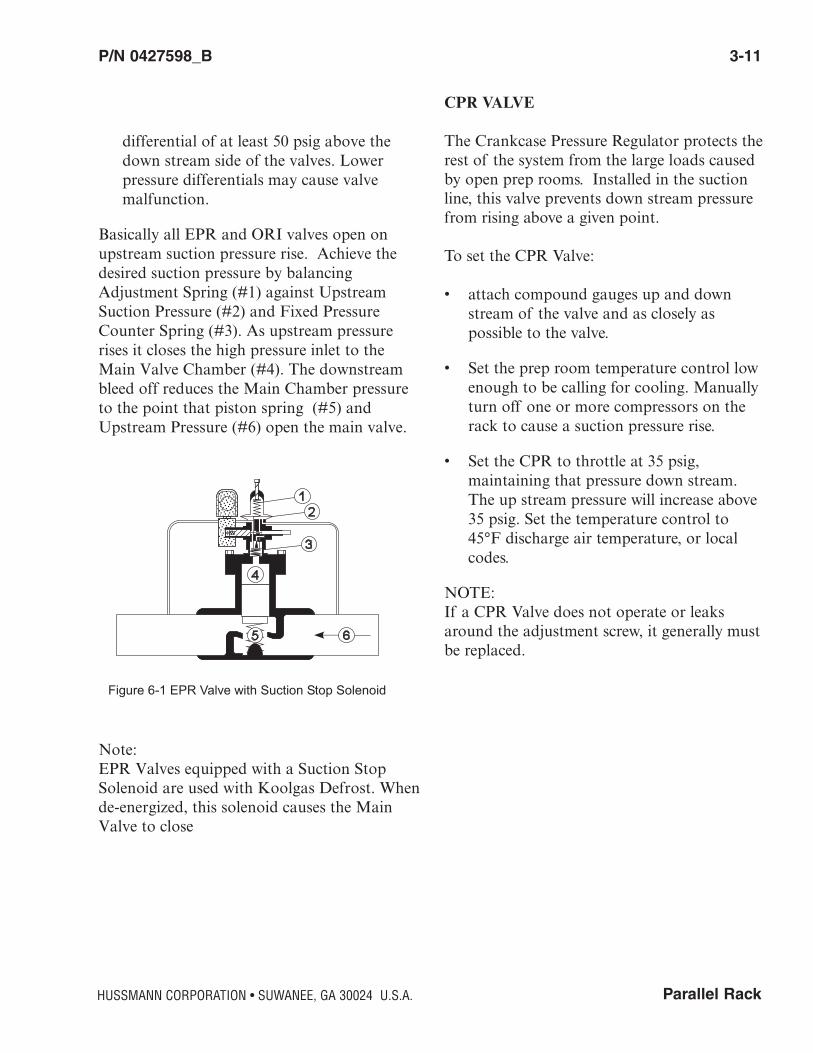
Basically all EPR and ORI valves open onupstream suction pressure rise. Achieve thedesired suction pressure by balancingAdjustment Spring (#1) against UpstreamSuction Pressure (#2) and Fixed PressureCounter Spring (#3). As upstream pressurerises it closes the high pressure inlet to theMain Valve Chamber (#4). The downstreambleed off reduces the Main Chamber pressureto the point that piston spring (#5) andUpstream Pressure (#6) open the main valve.
Note:EPR Valves equipped with a Suction StopSolenoid are used with Koolgas Defrost. Whende-energized, this solenoid causes the MainValve to close
CPR VALVE
The Crankcase Pressure Regulator protects therest of the system from the large loads causedby open prep rooms. Installed in the suctionline, this valve prevents down stream pressurefrom rising above a given point.
To set the CPR Valve:
• attach compound gauges up and downstream of the valve and as closely as possible to the valve.
• Set the prep room temperature control low enough to be calling for cooling. Manually turn off one or more compressors on the rack to cause a suction pressure rise.
• Set the CPR to throttle at 35 psig, maintaining that pressure down stream. The up stream pressure will increase above 35 psig. Set the temperature control to 45°F discharge air temperature, or local codes.
NOTE:If a CPR Valve does not operate or leaksaround the adjustment screw, it generally mustbe replaced.
HUSSMANN CORPORATION • SUWANEE, GA 30024 U.S.A.
Figure 6-1 EPR Valve with Suction Stop Solenoid
3-12 REFRIGERATION
P/N 0427598_B
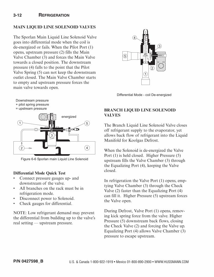
MAIN LIQUID LINE SOLENOID VALVES
The Sporlan Main Liquid Line Solenoid Valvegoes into differential mode when the coil is de-energized or fails. When the Pilot Port (1)opens, upstream pressure (2) fills the MainValve Chamber (3) and forces the Main Valvetowards a closed position. The downstreampressure (4) falls to the point that the PilotValve Spring (5) can not keep the downstreamoutlet closed. The Main Valve Chamber startsto empty and upstream pressure forces themain valve towards open.
Differential Mode Quick Test • Connect pressure gauges up- and
downstream of the valve. • All branches on the rack must be in
refrigeration mode. • Disconnect power to Solenoid. • Check gauges for differential.
NOTE: Low refrigerant demand may preventthe differential from building up to the valve’sreal setting — upstream pressure.
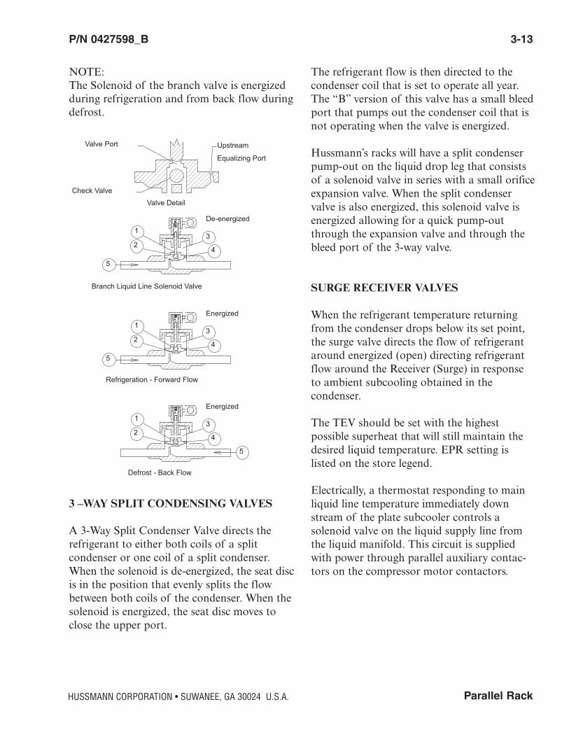
BRANCH LIQUID LINE SOLENOIDVALVES
The Branch Liquid Line Solenoid Valve closesoff refrigerant supply to the evaporator, yetallows back flow of refrigerant into the LiquidManifold for Koolgas Defrost.
When the Solenoid is de-energized the ValvePort (1) is held closed. Higher Pressure (5)upstream fills the Valve Chamber (3) throughthe Equalizing Port (4), keeping the Valveclosed.
In refrigeration the Valve Port (1) opens, emp-tying Valve Chamber (3) through the CheckValve (2) faster than the Equalizing Port (4)can fill it. Higher Pressure (5) upstream forcesthe Valve open.
During Defrost, Valve Port (1) opens, remov-ing kick spring force from the valve. HigherPressure (5) downstream back flows, closingthe Check Valve (2) and forcing the Valve up.Equalizing Port (4) allows Valve Chamber (3)pressure to escape upstream.
U.S. & Canada 1-800-922-1919 • Mexico 01-800-890-2900 • WWW.HUSSMANN.COM
Downstream pressure+ pilot spring pressure= upstream pressure
energized
1
2
3
4
5
Figure 6-6 Sporlan main Liquid Line Solenoid
5
4
3
2
1
Differential Mode - coil De-energized
Parallel Rack
P/N 0427598_B 3-13
NOTE:The Solenoid of the branch valve is energizedduring refrigeration and from back flow duringdefrost.
3 –WAY SPLIT CONDENSING VALVES
A 3-Way Split Condenser Valve directs therefrigerant to either both coils of a split condenser or one coil of a split condenser.When the solenoid is de-energized, the seat discis in the position that evenly splits the flowbetween both coils of the condenser. When thesolenoid is energized, the seat disc moves toclose the upper port.
The refrigerant flow is then directed to thecondenser coil that is set to operate all year.The “B” version of this valve has a small bleedport that pumps out the condenser coil that isnot operating when the valve is energized.
Hussmann’s racks will have a split condenserpump-out on the liquid drop leg that consistsof a solenoid valve in series with a small orificeexpansion valve. When the split condenservalve is also energized, this solenoid valve isenergized allowing for a quick pump-outthrough the expansion valve and through thebleed port of the 3-way valve.
SURGE RECEIVER VALVES
When the refrigerant temperature returningfrom the condenser drops below its set point,the surge valve directs the flow of refrigerantaround energized (open) directing refrigerantflow around the Receiver (Surge) in responseto ambient subcooling obtained in the condenser.
The TEV should be set with the highest possible superheat that will still maintain thedesired liquid temperature. EPR setting is listed on the store legend.
Electrically, a thermostat responding to mainliquid line temperature immediately downstream of the plate subcooler controls a solenoid valve on the liquid supply line fromthe liquid manifold. This circuit is suppliedwith power through parallel auxiliary contac-tors on the compressor motor contactors.
HUSSMANN CORPORATION • SUWANEE, GA 30024 U.S.A.
De-energized1
23
4
5
Branch Liquid Line Solenoid Valve
Refrigeration - Forward Flow
Defrost - Back Flow
Valve Port
Check Valve
Upstream
Equalizing Port
Valve Detail
Energized1
23
4
5
Energized1
23
4
5

3-14 REFRIGERATION
P/N 0427598_B
A liquid line solenoid valve and a TEV controlrefrigerant flow to the plate heat exchanger.An EPR on the return suction line prevents thesubcooler temperature from dropping belowdesired liquid temperature.
Thermostat setting is 50°F with minimum differential, or customer specifications. The TEV should be set with the highest possible superheat that will still maintain thedesired liquid temperature.
EPR setting is listed on the store legend.
LIQUID LINE DIFFERENTIAL VALVEADJUSTMENT
1) Shut off the Kool/Hot gas ball valve on thefirst gas defrost circuit and put that circuit in defrost. Make sure that no other circuits that are gas defrost, are in, or will go in defrost while adjustments are being made.
2) Connect two high side gauges, one on each side of the liquid line differential valve.
3) Subtract the outlet pressure from the inlet pressure, this is your differential pressure.
4) If adjustment is necessary, turn valve adjustment stem in the clock wise directionto increase the deferential pressure and turnit counter clock wise to reduce the deferential pressure.
5) Remove the high side gauges.
6) Take the first gas defrost circuit out of defrost and open the Kool/Hot gas ball valve for that circuit.
SORIT EVAPORATOR PRESSUREREGULATOR ADJUSTMENT
1) Connect a low pressure gauge to the suction manifold.
2) Connect a low pressure gauge to the evaporator side of the SORIT valve in needof adjustment.
3) Make sure the suction header pressure is 5 to 10 psig lower than the desired set point.
4) Turning the SORIT valve adjustment stem in the clock wise direction will cause the evaporator pressure to go up. Turning the stem in the counter clock wise direction willcause the evaporator pressure to go down.
5) Wait a few minutes to allow system pressures to stabilize then recheck the SORIT valve set point.
6) Remove the low side gauges.
LOW PRESSURE CONTROLS
1) Turn off the control circuit for the compressor that needs it’s low pressure control set.
2) Bypass any time delays, electronic rack control relay, electronic overload module with built in time delay and switch back relay if used.
3) Connect a low pressure gauge to the suction header.
4) Front seat oil supply and oil equalizer line service valves on the compressor whose lowpressure control is being adjusted.
U.S. & Canada 1-800-922-1919 • Mexico 01-800-890-2900 • WWW.HUSSMANN.COM

Parallel Rack
P/N 0427598_B 3-15
5) Make sure rack suction pressure is above the desired cut in point of the low pressure control. You may have to turn off the othercompressors to raise the suction pressure.
6) Connect a low pressure gauge to the compressor suction service valve on the compressor whose low pressure control is being adjusted.
7) Front seat the suction service valve.
8) Jump out the low pressure control and turnon the compressor. Look at the gauge
connected to the suction service valve, whenthe pressure reaches 0 psig turn off the compressor.
9) Adjust the cut in point of the low pressure control 20 to 25 psig above the desired cut in point by looking at the scale on low pressure control.
10) Slowly open the suction service valve and watch the low pressure gauge. When the pressure reaches the desired cut in close offthe suction service valve.
11)Remove the jumper on the low pressure control. Turn the compressor control circuiton. Slowly turn the cut in adjustment toward the desired cut in point. When the compressor turns on you have reached yourdesired cut in point.
12) Slowly open the suction service valve and watch the gauge connected to the suction service valve. Make sure the compressor cuts in at the proper pressure. If fine tuningof the low pressure control is needed, front seat the suction service valve again then adjust the cut in on the low pressure control.
13) Slowly open the suction service valve while watching the gauge connected to the suction service valve. Repeat until the desired cut in point is reached. When you are finished adjusting the cut in of the low pressure control open the suction service valve fully.
14) Turn the deferential adjustment on the low pressure control to a value greater than your desired cut out point.
15)Slowly front seat the suction service valve while watching the gauge connected to the suction service valve. When the desired cut point is reached stop turning the suction service valve.
16)Slowly turn the deferential adjustment on the low pressure control towards the desiredcut out point. When the compressor turns off you have reached your desired cut out point.
17) Open the suction service valve fully then begin to front seat it while watching the gauge connected to the suction service valve. Make sure the compressor cuts out atthe proper pressure. If fine tuning of the low pressure control is needed, adjust the cut out on the low pressure control. Repeat this step until the desired cut out point is reached. When you are finished adjusting the cut out of the low pressure control open the suction service valve fully.
HUSSMANN CORPORATION • SUWANEE, GA 30024 U.S.A.

3-16 REFRIGERATION
P/N 0427598_B
18)Disconnect the low pressure gauges from the system.
19) Open oil supply and oil equalizer line service valves that were closed during Step 4.
20) Turn off the control circuit on the compressor whose low pressure control youset.
21) Remove any jumpers you installed during Step 2.
22) Turn the compressor control circuit back on.
High Pressure Control Adjustment
1) Set the cut out of the high pressure control to the desired set point. Use the scale on the high pressure control to set cut out point.
2) Set the cut in of the high pressure control to the desired set point. Use the scale on thehigh pressure control to set cut in point.
CONTROL SETTINGS GENERAL DESCRIPTION
There are nine potential control settingsrequired to be set up prior to startup. They areas follows: • Low Pressure Controls • Satellite Pressure Controls • Compressor Oil Failure Controls • Heat Reclaim Lockout • Split Condenser Control Settings • Condenser Settings • Winter Condensing Pressure Controls • EPR Pressure Settings • Defrost Timer Settings • Inverter Settings
U.S. & Canada 1-800-922-1919 • Mexico 01-800-890-2900 • WWW.HUSSMANN.COM

Parallel Rack
P/N 0427598_B 4-1
HUSSMANN CORPORATION • SUWANEE, GA 30024 U.S.A.
ELECTRICAL OVERVIEW
Custom wiring schematics are located on thedoors of each rack. Racks are wired for 208-230/3/60 or 460/3/60. Other voltages areavailable upon request. The control circuit istypically 208VAC but racks can be orderedwith a single point connection (optional).Refer to the serial plate located on the controlpanel to determine MCA MOPD.
Refer to merchandiser Data Sheets for electrical supply requirements for cases.
FIELD WIRING
Rack components are wired as completely aspossible at the factory with all work completedin accordance with the National ElectricalCode (NEC). All deviations required by gov-erning electric codes will be the responsibilityof the installer.
The lugs on the circuit braker package in thecompressor control panel are sized for copperwire only. All wiring must be in compliancewith governing electrical codes.
For Remote Header Defrost Assembly: To the defrost control panel provide, one 208V,1PH, 15A branch circuit, or one 120V, 1PH,15A branch circuit for control power only. One208V 3PH branch circuit for electric defrostpower, one communications circuit for electronic controller output/input boards. The120V and 208V circuits may originate at theparallel rack or from a separate source.
Consult the store legend or electrical plans foreach installation.
For 208-230/3/60 Compressor Units:To each parallel rack compressor provide, one208-230/3/60 branch circuit, one 120V, or one208V 1PH 15A circuit. Omit when single pointconnection kit is used.
Provide one 208-230/3/60 branch circuit toeach remote air-cooled condenser. Dry contacts are made available upon request atthe rack control panel. Contacts will close inalarm state. Contact rating is 10A at 208V.Alarm status may be configured through anelectronic controller.
REQUIRED FIELD WIRE SIZE
Based on the full load amps of the system,select the largest connectable wire size from thetable. (Based on no more than three wires inthe wireway and 30°C environment per NEC.)Total Connected FLA Largest ConnectableWire:
140A (max) 00 per 248A (max) 350 mcm 408A (max) 2x (250 mcm) per 608A (max) 2x (500 mcm) per
Include control circuit amps if single pointconnection transformer option is used. 12A for 208V systems 6A for 460V systems(Refer to NEC for temperature derating factors.)
ELECTRICAL
4-2 ELECTRICAL
P/N 0427598_B U.S. & Canada 1-800-922-1919 • Mexico 01-800-890-2900 • WWW.HUSSMANN.COM
WIRING COLOR CODELeads for all electrical circuits are identified by a colored plastic band:neutral wire for each circuit has either White insulation or a White plas-tic sleeve in addition to the color band.
PINK ............REFRIG. THERMOSTAT LOW TEMP. ORANGE ORLIGHT BLUE .REFRIG. THERMOSTAT NORM TEMP. TAN..........LIGHTSDARK BLUE..DEFROST TERM. THERMOSTAT MAROON ..RECEPTACLESPURPLE .......CONDENSATE HEATERS YELLOW....DEFROST HEATERS 120VBROWN ........FAN MOTORS RED ........DEFROST HEATERS 208VGREEN* .......GROUND *EITHER COLORED SLEEVE OR COLORED INSULATION
ELECTRICIAN NOTE: Use copper conductor wire only. CASE MUST BE GROUNDED
MERCHANDISER ELECTRICAL DATA
Technical data sheets are included with this manual. The data sheets provide merchandiserelectrical data, electrical schematics, parts listsand performance data. Refer to the technicaldata sheets and merchandiser serial plate forelectrical information.
MERCHANDISER FIELD WIRING
Field wiring must be sized for componentamperes stamped on the serial plate. Actualampere draw may be less than specified. Fieldwiring from the refrigeration control panel tothe merchandisers is required for defrost termination thermostats and for optionalrefrigeration thermostats. When multiple merchandisers are on the same defrost circuit,the defrost termination thermostats are wired inseries.
ALWAYS CHECK THE SER IAL PLATE FORCOMPONENT AMPERES.
ELECTRICAL CONNECTIONS
All wiring must be in compliance with NECand local codes. All electrical connections areto be made in the electrical wireway or Handy Box.
IDENTIFICATION OF WIRING
Leads for all electrical circuits are identified bycolored plastic bands. These bands correspondto the color code sticker (shown below) locatedinside the merchandiser’s wireway cover.
The defrost heaters, defrost termination thermostats and refrigeration thermostats onthe wide island models are tagged with identification as being either front or rear merchandiser display section defrost andrefrigeration controls.
Parallel Rack
P/N 0427598_B 4-3
HUSSMANN CORPORATION • SUWANEE, GA 30024 U.S.A.
ELECTRICAL DIAGRAMS
All electrical schematics reflect the standardladder diagram. Electrical schematics areincluded with each rack. Please keep in mindall diagrams in this manual are only examples!Wiring may vary, refer to the diagram includedwith each rack. To focus on circuit logic thediagram may separate a relay coil and it’s contacts. Electrical terminal connections areclearly numbered and aid in trouble shootingshould a problem arise.
Unit cooler fan wiringSee manufacturer’s literature for wiringrequirements. Evaporator mounted liquid linesolenoid power for a liquid line solenoid can bepicked up at the rack on terminals C and R foreach respective circuit.
Cooler Door Switch Wiring Check the store legend for door switch requirements. The switch must be mounted tothe cooler door frame, and must be wired tocontrol the field installed liquid line solenoidand the fan circuit. For Koolgas applications,install a check valve to bypass the liquid linesolenoid valve.
COMPONENT WIRING GUIDELINES
Check the store legend for components requir-ing electrical circuits to either the panel, whichmay include: • Remote alarm • Electronic temperature probe • Defrost termination thermostat • Thermostat controlling a liquid line
solenoid • Satellite control • Heat reclaim contact or 24V supply All thermostat wires should be sized for rackcontrol circuit breaker. Temperature sensor
wiring should refer to the controller manufacturer’s literature. Check field wiringrequirements for appropriate quantity of wires.
Sizing Wire and Overcurrent Protectors Check the serial plate for minimum circuitampacity (MCA) and maximum overcurrentprotective devices (MOPD). Follow NECguidelines.
Other Controls Refer to the wiring schematics included withthe rack, when other controls are used.
COMPRESSOR CONTROL
Each control panel is wired with independentcompressor control circuits so any compressorcan be electrically isolated without causing theother compressors to be shut down, A typical compressor control will consist ofthe following:
• Electrical control • Switchback relay contacts (optional)• Switchback time delay (optional)• Low pressure switch • High pressure switch • Oil pressure switch• Overload contact (if used)• Contactor coil• Demand cooling control (if used) • Crankcase heater (optional) • Lighted toggle switch Terminal pins will be used between controlpoints for easy testing and troubleshooting.

4-4 ELECTRICAL
P/N 0427598_B U.S. & Canada 1-800-922-1919 • Mexico 01-800-890-2900 • WWW.HUSSMANN.COM
ELECTRONIC CONTROLLER
The electronic controller uses a suction transducer to “read” the suction manifold pressure. From this, sequence compressors onor off through a relay board to achieve the target suction pressure.
TIME DELAY
Automatic time delays are built into most electronic controllers. This helps avoid shortcycling. A solid state time delay will be usedfor backup in the unlikely event of a electroniccontroller failure. The time delay will only bein the circuit during switch back, if the systemuses switch back control.
If the system does not have optional switchback control then it will be wired in series withthe operating controls. Awareness of timedelays will reduce frustration and confusionwhen starting or troubleshooting the system.
PRESSURE SWITCHES
There are basically three pressure switches inthe compressor control circuit. A low pressureswitch is used to close the control circuit during high suction and open the circuit dur-ing low suction pressure. A high pressureswitch is used to open the control circuit dur-ing a critical high discharge pressure state. Thehigh pressure switch is available in automaticor manual reset. An oil pressure switch sensesthe supply oil pressure when the compressor isrunning.
If the oil pressure falls below the preset setting,the control circuit will open. Oil pressureswitches are preset for 6.5 psig differential(Carlyle) and 9 psig differential (Copeland).The oil failure time delays are preset for 45 seconds (Carlyle) and 120 seconds (Copeland).
*For proper setting of switches see control settings section.
SWITCHBACK CONTROL (OPTIONAL)
During “normal” operation, the switchbackrelay will be de-energized allowing the electronic controller to be in full control. Whenthe controller looses power or malfunctions.the switchback relay will energize which in turnwill bypass the control power around the electronic controller and through the low pressure switch and time delay.
CRANKCASE HEATERS (OPTIONAL)
A crankcase heater is used to alleviate liquidmigration to the compressor during off cycleperiods. The crankcase heater is interlockedthrough the compressor contactor to be powered when the compressor is not running.
OIL FAILURE RELAY
This relay is used during an oil failure to jumpthe electronic controller relay. This will elimi-nate multiple alarms if the suction pressuredrops and the compressor control point openswithout the oil failure relay, the suction pres-sure would eventually rise causing another oilfailure alarm.
CURRENT RELAY (OPTIONAL)
A current relay is wired in series with the oilfailure control heater. This will prevent a falseoil trip if the compressor circuit breakershould trip or if the compressor goes off oninternal overload.

Parallel Rack
P/N 0427598_B 4-5
HUSSMANN CORPORATION • SUWANEE, GA 30024 U.S.A.
DEFROST CONTROLS
There are many types of defrost circuits andthey are shown on the Defrost diagram in therack. These circuits may be repeated in multiple and intermixed in any one store. Each control panel is wired with independentdefrost control circuits so any circuit can beelectrically isolated without causing the othercircuits to be shut down.
A typical defrost circuit will consist of the following:
• Lighted toggle switch. • Pins R and C for refrigeration power
circuit. • Pins D and C for defrost power circuit. • N.C. contacts for refrigeration. • N.O./N.C. contacts for defrost. • Pins E and F for defrost termination. (Dry
contact only) • Pins T and B for temperature control
thermostat (Dry contact only) or Temperature probes can be used for electronic controllers.
Refrigeration Mode:During refrigeration, both the defrost pointand refrigeration point are de-energized allowing L1 power to flow to the SV valve(Sorit or Liquid Solenoid). If case probes areused with the controller the refrigeration pointwill open when a system reaches proper operation temperature. Thus closing the refrigeration valve.
Defrost Mode: The defrost point will energize opening powerto the SV valve, refrigeration point. and closing power to the Kool/Hot gas valve(HGV) or defrost contactor (DC).
TEMPERATURE CONTROLS
Refrigeration Thermostat (Alternate) If it is desired to have the refrigeration thermostat operate the branch liquid line solenoid on the compressor unit, wire it to thecontrol panel in the following manner.Determine the system number from the storelegend. The system will be on the suffix of theappropriate “T” and “B” terminals.
a. Remove the jumper from the T and B terminal.b. Connect one thermostat wire to the T terminal.c. Connect the other thermostat wire to the Bterminal.
Case Probe (Alternate)If it is desired to monitor case temperature andoperate a branch liquid line circuit, wire a caseprobe from the case to an analog point on theelectronic controller. Provisions for case probesmay be made from the field or factory. Refer tothe controller manual for setup.
Defrost Termination Thermostat For each system using defrost terminationthermostats, run a two-wire control circuitfrom all termination thermostats (in series, oneper case) to the E_ and F_ terminals in thecontrol panel with a suffix corresponding tothe system number.
Note: The defrost termination thermostat mustsupply a dry contact closure. An isolationrelay must be used for a “hot” terminationthermostat.
Master Defrost Valve The master defrost valve is used during ahot/kool gas defrost cycle to create a reverseflow through the evaporator
4-6 ELECTRICAL
P/N 0427598_B U.S. & Canada 1-800-922-1919 • Mexico 01-800-890-2900 • WWW.HUSSMANN.COM
ALARM CONTROL
Alarm System The rack basic alarm package includes alarmsfor: • Oil Failure (each compressor) • Phase Loss • Low Liquid Level* • High Suction* • High Discharge • Compressor Failure
*Time Delayed
A dry set of contacts are supplied to control aremote bell or other alarm device. These contacts are rated at 10.0 amps, 120 volt. Anindicator light signifies what alarm conditionhas been activated.
Note: If an electronic rack controller is utilized. then the above alarms will preformedby the rack controller.
Ladder diagrams emphasize the circuit continuity and logic. They aid troubleshootingand testing by identifying point-to-point connections, and color coding rather than justphysical location. A ladder diagram normallymoves from left to right so the user can “read”the series of switches, relays, terminals and components that make up a circuit.
Alarm Control (Electronic) When an Electronic Rack Controller is utilizedall alarm functions are preformed by the rackcontroller. High suction and high dischargepressures are “read” by transducers connectedto the rack controller. The liquid level caneither be a digital input (standard) or an analog type input.
The controller can display actual refrigerantlevel with the analog type (optional). Phaseloss, oil failure, and the compressor failurealarms are connected to the rack controllerthrough a digital input. An optional modemcan be installed to allow the rack controller tocall out any refrigeration alarms.
Alarm SystemsThe following alarms are available for use withthe parallel rack system:
1. Refrigerant Loss Alarm/Indicator: An alarmtrips if the refrigerant level in the receiver drops below a set level. This alarm automatically compensates for changes in liquid level occurring during heat reclaim.
2. Single Phase Protection: This shuts down the control circuit during single phasing of the power circuit; automatically resets when three phase power is restored.
3. Remote Alarm: In event of a power outage or any alarm condition, an alarm will soundat another location, such as a burglar alarm monitoring station or answering service.
INVERTOR CONTROL
An inverter is used to vary the speed of a compressor which in turn varies the capacity ofthat compressor. With the ability to vary thecapacity of a compressor, refrigeration require-ments can be better matched to the load.
Parallel Rack
P/N 0427598_B 4-7
HUSSMANN CORPORATION • SUWANEE, GA 30024 U.S.A.
Unit Cooler Fan WiringProvide a 120/1/60 fused power supply foreach cooler. (Check the store legend to see if208-230/1/60 is required at this location.)
Evaporator Mounted Liquid Line SolenoidPower for a liquid line solenoid in the merchandiser can be picked up from the fancircuit. (Check fan motor and solenoid voltages first.)
Cooler Door Switch Wiring Check the store legend or electrical plans, fordoor switch kits. The switch must be mounted to the cooler door frame, and mustbe wired to control the field-installed liquidline solenoid and evaporator fans. Doorswitches are wired in series. For Koolgasapplications, kit M116 includes a check valveto bypass the liquid line solenoid valve.
Sizing Wire and Overcurrent ProtectorsCheck the serial plate for Minimum CircuitAmpacity (MCA) and Maximum OvercurrentProtective Devices (MOPD). Follow NECguidelines.
4-8 ELECTRICAL
P/N 0427598_B U.S. & Canada 1-800-922-1919 • Mexico 01-800-890-2900 • WWW.HUSSMANN.COM
NOTES:

LEAK TESTING
NOTE:Leaks harm the ozone layer and can be veryexpensive. It is very important to follow EPAGreenchill Installation Leak TightnessGuidelines as well as Greenchill LeakPrevention and Repair Guidelines.
Check that the compressor’s primary ON-OFF switch are all in the OFF position.
NOTE: Do not start any compressors without ensuringthere is oil in them. Serious damage to thecompressors may result from not having oil inthem.
Always use a pressure regulator with a nitrogen tank. Do not exceed two pounds ofpressure and vent lines when brazing. Do notexceed 350 pounds of pressure for leak testinghigh side. Do not exceed 150 pounds of pressure for leak testing low side.
To check for system leaks do the following:
• Leave all valves closed to allow pressure into the rack. Close the suction, liquid or hot gas manifolds. Each rack system is shipped with dry Nitrogen. Build the pres-sure in the rack unit until it reaches 150 psi. Each individual circuit should be checked.
• Each circuit can be leak checked as the pressure increase to 150 psi. Ensure that
the pressure is the same throughout the assembly. Check connections and accessories for any leaks. Use an electronic leak detector. Inspect all joints. If the pressure drops sharply, this is an indicationof a leak. Visually inspect all lines and joints for proper piping practices.
• Once the system has been thoroughly tested, evacuate the system to 1500 microns for the first evacuation.
• The evacuation is repeated. Install liquid and drier cores before the second evacuation.Suction filter cores are factory installed. After each evacuation, the system must be pressurized to 2 psig with dry nitrogen.
• Now evacuate the system to 500 microns for the second evacuation. Perform three evacuations in all.
PRE-CHARGE CHECK LIST
While the system is being evacuated prepara-tion for charging can begin. During any of thepull downs check:
• Merchandiser’s electrical requirements and power supply electrical connections are tight and clean
• Check for proper fan operation and thermostat setting.
• Walk-in coolers and freezers electrical requirements and power supply
• Damper operation, if equipped. • Heat Reclaim and other systems
Parallel Rack
P/N 0427598_B 5-1
HUSSMANN CORPORATION • SUWANEE, GA 30024 U.S.A.
START-UP
Know whether a circuit is open at the powersupply or not. Remove all power before
opening control panels. Note: Some equipment has more than one power supply.
5-2 START-UP
CHARGING
• Open compressors – backseat service valves on suction and discharge.
• Open oil supply line immediately downstream of the oil separator.
• Pressure transducers – open angle valves. •connect defrost time clock and set proper time.
• Leave open ball valves – to branches, condenser, heat reclaim, receiver.
• Main liquid line solenoid valve – now under control of defrost clock.
• Branch liquid line solenoid valve – Back out manual open screws.
• Suction stop EPR – under control of defrost clock.
• Split condenser – operation under pressure controls.
Note:Remember to reinstate control to unit components jumpered to make test.
Set all mechanical pressure controls. Compressorsshould still be isolated from the rest of thesystem. Set all electronic compressor controlsinto switchback so the mechanical controls arein command of all system functions.
During the last evacuation look up and makea list of the required control settings for thesystem. A copy of the equipment legend willbe needed to determine the system’s designoperating points. High and low pressure, heatreclaim lockout, winter control settings, andother controls on the system should be noted.
Oil Levels Check oil levels for each compressor and theTurba-shed or other oil separator: Compressorsight glass 1/8 to ½ full, oil separator betweentwo lower sight glasses. See legend for oil typesused in parallel rack system.
If the oil is low, add the appropriate oil orlubricant to match the refrigerant used.
P/N 0427598_B U.S. & Canada 1-800-922-1919 • Mexico 01-800-890-2900 • WWW.HUSSMANN.COM
Additionally, check for the following during leak test:
Isolate compressors – front seat servicevalves on suction and discharge. close oilsupply line immediately downstream ofthe oil separator.
Pressure transducers – close angle valves.
Open ball valves – to branches, condenser,heat reclaim, receiver.
Main liquid line solenoid valve - solenoid should be non regulating position.
Branch liquid line solenoid valve - solenoid should be energized or manualopen used.
Suction stop EPR valves – suction stopEPR requires energized solenoid to beopen.
Split condenser – both sides open. de-energize valve solenoid.
Defrost time clock – disconnect power tothe clock or set electronic controllers in manual. Be sure all branches are in refrig-eration mode.
Verify refrigerant requirements for system,Compressors, and TEVs in merchandisersand coolers.
Electrical supply and component requirements.
Always recapture test charge in approvedrecovery vessel.
Evacuation Nitrogen and moisture will remain in the system unless proper evacuation proceduresare followed. Nitrogen left in the system maycause head pressure problems. Moisture causes TEV ice blockage, wax build up, acidoil and sludge formation.
• Do not simply purge the system.This procedure is expensive, harmful to the environment, and may leave moisture and nitrogen behind.
• Do not run the compressors to evacuate. This procedure introduces moisture into the compressor’s crankcase oil and does not produce adequate vacuum to remove moisture from the rest of the system at normal temperatures.
Final Checks Once the rack is up and running, it is theresponsibility of the installer to see that all thefine adjustments are made so the rack deliversmaximum temperature performance and effi-ciency for the customer.
These adjustments include:
• Defrost scheduling and timing • Condenser controls • Winter controls • Sub-cooling Compound System Operation
EPR, and ORI settings • TEV superheat adjustment • CPR settings High and low pressure
controls Main liquid line solenoid differential
Thermostat settings Adjustments to electronic controls:
Thoroughly inspect all field piping while theequipment is running and add supports whereline vibration occurs. Be sure additional sup-ports do not conflict with pipe expansion andcontraction.
When merchandisers are completely stocked,check the operation of the system again. At 48 hours of operation replace the liquiddrier and suction filter cores.
At 90 days recheck the entire system, includ-ing all field wiring. Change the oil filter.Future maintenance costs may be reduced ifan oil acidity test is run at this time. Replaceacidic oil.
LIQUID DRIER CORE REPLACEMENT
Replace liquid drier cores 24 hours after initialstartup.
After 48 hours of operation, replace the driercores again. Any time the system is openedafter this point, the dryer cores shall bereplaced.
SUCTION FILTER CORE REPLACEMENT
Replace suction filter cores 24 hours after initial startup.
After 48 hours of operation, inspect suctionfilter cores and replace and repeat if they arefull of dirt and debris.
P/N 0427598_B 5-3
Parallel RackHUSSMANN CORPORATION • SUWANEE, GA 30024 U.S.A.
Never trap liquid refrigerant between closedvalves as this could cause a hydraulic explosion.

5-4 START-UP
U.S. & Canada 1-800-922-1919 • Mexico 01-800-890-2900 • WWW.HUSSMANN.COMP/N 0427598_B
NOTES:
Intentionally venting or discharging CFC, HFCand HCFC refrigerant violates Federal Law. All CFC, HFC and HCFC refrigerants must be
reclaimed and recycled in accordance with all state, federal and local laws.

COMPRESSOR REPLACEMENT
Since each machine room tends to be unique,plan carefully as to how you will move thecompressor without harming personnel, equipment or the building. Before beginningremoval of an old compressor make replace-ment unit ready to install:
Verify Replacement compressor electricalrequirements, refrigerant, application, capacity, piping hookup location and design suction and discharge gaskets
Mounting requirements:Have compressor in an easily accessible position, uncrated and unbolted from shipping pallets.
Disconnect electrical supply: Turn off motor and control panel power supplies to the Rack. Turn off control circuitand open all compressor circuit breakers. Tag and remove electrical wires and conduitfrom the compressor.
Isolate compressor from rack: Frontseat suction and discharge service valves.Close oil supply and equalizing lines. Bleed compressor pressure through both discharge and suction access ports into anapproved recovery vessel.
Remove oil supply and equalizing lines. Remove externally mounted components whichwill be re-used on the replacement compressor. Plug holes to compressor manufacturer’s specifications.
Remove bolts from suction and discharge ser-vice valves.
Remove mounting bolts. When moving the compressor, use a come-along, hoist or hydraulic lift to carry theweight.
Do not use the rack piping or panel to supporta hoist or come-along.
Do not use ceiling trusses to support a hoist orcome-along.
The rear support channel on the rack or aproperly constructed ceiling rail may be usedto support a hoist or come-along.
To make hookup and lifting easier, an eye boltmay be installed in the rear top of the compressor head.
P/N 0427598_B 6-1
Parallel RackHUSSMANN CORPORATION • SUWANEE, GA 30024 U.S.A.
MAINTENANCE
If a compressor removal table is used, slide thecompressor fully on to the table, then roll tableto overhead hoist or hydraulic lift area.
When the old compressor has been removed,clean the suction and discharge service valvegasket surfaces to shiny metal. Clean the gas-ket surfaces on the new compressor to shinymetal. Be careful not to groove or round thesurfaces. Gasket surfaces must be clean to pre-vent leaking.
Install the new compressor in reverse order ofremoval. Do not open the new compressor tothe system until after it has been leak testedand triple evacuated.
Note: Oil level regulator sight glasses aredesigned to provide a hermetic seal when inter-nally pressurized. Some leaking may occurwhen a deep vacuum is pulled.
Cleaning the Turba-Shed (Oil Separator)Should the oil separator require cleaning, firstshut down the system. Isolate the oil separatorand bleed off pressure into an approved recovery vessel. Remove the top and bottomsight glasses and the oil supply line. With aclean, dry, regulated pressure source like nitrogen, blow out any sludge or dirt. Installthe sightglasses using new o-rings.
Parker Number 2-23, Compound 557 Precision Rubber, number 023, Compound 2337
Leak test, evacuate, and charge with fresh oilrefer to legend for oil type. Open valves closedto isolate the oil system and bring the rackback on line.
Replacing Drier and Filter Cores:Shut down the system. Isolate the core to bereplaced and bleed off pressure into anapproved recovery vessel. Open housing,replace core and close up. Pressurize, leak testand bring back into line.
WINTER CONDENSING PRESSURE CONTROLS
Five methods are used to control condensingpressure during cold weather operation.
1) Flooding valves must be applied to the compressor unit when winter temperatures are expected.
2) Temperature Control: Fans are thermostatically controlled and cycled accordingly to outside temperature. Can be applied to single circuited condensers.
3) Thermal Fantrol: Used with multi-circuited condensers. Fans are cycled according to outside temperatures.
4) Split Condensers: (factory or field installed) Used on dual circuit condenser with or without heat reclaim, where a four-way solenoid valve (controlled by ambient sensing temperature control or pressure control) activates to cut off one half of the condensers. Field-installed situations will require double discharge and double condenser leg return piping.
6-2 MAINTENANCE
P/N 0427598_B U.S. & Canada 1-800-922-1919 • Mexico 01-800-890-2900 • WWW.HUSSMANN.COM
GENERAL MAINTENANCE
Regular inspection and upkeep is critical tooperation of the rack. Because of the numer-ous options and accessories that are unique toeach store, it is impossible to list all of themaintenance guidance for individual systems.
Maintenance must be performed by a well qualified technician to diagnose and preventproblems before they may occur. The informa-tion below is a general guideline.
Recommended service intervals in your area mayvary depending on the operating environmentand equipment used. Contact your Hussmannrepresentative for further information.
Generally, the following items should be checkedon a weekly basis:
• System Pressures• Main Power Voltage• Oil Levels• Refrigerant Charge
Generally, the following items should be checkedon a monthly basis:
• System pressures• System leak tests• All filters and drier cores• Insulation, conduit, electrical boxes and control panels
• Secondary systems, and accessories• Fan motors, contactors and electrical connections
• Check for tightnesss of fittings, fan blades and motor mounts
Generally, the following items should be checkedon a quarterly basis:
Investigate operating conditions for the following:
• Suction, liquid, and discharge pressures and temperatures
• Sub-cooling, superheat and ambient temperatures
• Safety controls, operating controls and alarms
• Amperage coming from Compressors
Each year, check the following:
• Clean the condenser coil• Straighten or replace all fan blades • Change the filter drier and suction cores• Get an oil sample and determine the quality and change if required
P/N 0427598_B 6-3
Parallel RackHUSSMANN CORPORATION • SUWANEE, GA 30024 U.S.A.

Service Notes:
6-4 MAINTENANCE
P/N 0427598_B U.S. & Canada 1-800-922-1919 • Mexico 01-800-890-2900 • WWW.HUSSMANN.COM

DRIER AND FILTER CORES REPLACEMENT
Replacing Drier and Filter Cores Shut down the system. Isolate the core to bereplaced and bleed off pressure into anapproved recovery vessel. Open housing,replace core and close up. Pressurize, leak testand bring back into line.
WINTER CONDENSING PRESSURE CONTROLS
Five methods are used to control condensingpressure during cold weather operation.
1. Flooding valves must be applied to the compressor unit when winter temperatures are expected.
2. Temperature Control: Fans are thermostaticallycontrolled and cycled accordingly to outside temperature. Can be applied to single circuitedcondensers.
3. Pressure Control: Pressure regulates condensing according to need to cycling fansaccording to compressor discharge pressure, can be applied to single-circuited condensers.
4. Thermal Fantrol: Used with multi-circuited condensers. Fans are cycled according to outside temperatures.
5. Split Condensers: (factory or field installed)Used on dual circuit condenser with or without heat reclaim, where a four-way solenoid valve (controlled by ambient sensing temperature control or pressure control) activates to cut off one half of the condensers. Field-installed situations will require double discharge and double condenser leg return piping.
P/N 0427598_B 7-1
Rack SystemsHUSSMANN CORPORATION • SUWANEE, GA 30024 U.S.A.
SERVICE

7-2 SERVICE
P/N 0427598_B U.S. & Canada 1-800-922-1919 • Mexico 01-800-890-2900 • WWW.HUSSMANN.COM

®
To obtain warranty information or other support, contact your
Hussmann representative. Please include the model and serial number of the product.
Hussmann Corporation, Corporate Headquarters: Bridgeton, Missouri, U.S.A. 63044-2483 October 2012

Hussmann Corporation 2700 Crestridge CourtSuwanee, GA 30024
www.hussmann.com