hvac design using vantage pdms - pdms training and...
TRANSCRIPT

pdms114/man7/doc1Issue 140502
HVAC Design Using VANTAGE PDMS
Volume 1
Version 11.4

Cadcentre Ltd, High Cross, Madingley Road, Cambridge CB3 0HB, UK
PLEASE NOTE:
Cadcentre has a policy of continuing product development: therefore the information containedin this document may be subject to change without notice.
CADCENTRE MAKES NO WARRANTY OF ANY KIND WITH REGARD TO THISDOCUMENT, INCLUDING BUT NOT LIMITED TO, THE IMPLIED WARRANTIES OFMERCHANTABILITY AND FITNESS FOR A PARTICULAR PURPOSE.
While every effort has been made to verify the accuracy of this document, Cadcentre shall notbe liable for errors contained herein or direct, indirect, special, incidental or consequentialdamages in connection with the furnishing, performance or use of this material.
This manual may provide documentation relating to products to which you do not haveaccess or which are not licensed to you. For information on which products are licensed toyou, please refer to your licence conditions.
E Copyright 1994 through 2002 Cadcentre Limited
All rights reserved. No part of this document may be reproduced, stored in a retrieval systemor transmitted, in any form or by any means, electronic, mechanical, photocopying,recording or otherwise, without prior written permission of Cadcentre.
The software programs described in this document are confidential information andproprietary products of Cadcentre Ltd or its licensors.
For details of Cadcentre’s worldwide sales and support offices, access our website athttp://www.cadcentre.com/location

iHVAC Design Using VANTAGE PDMSVersion 11.4
Contents
Volume 1
Part I Introduction
1 Read This First
1.1 The Scope of the Guide 1--1. . . . . . . . . . . . . . . . . . . . . . . . . . . . .1.2 Learning to Use PDMS 1--1. . . . . . . . . . . . . . . . . . . . . . . . . . . . .1.3 Further Training in the Use of PDMS 1--2. . . . . . . . . . . . . . .1.4 Some Terms and Conventions 1--3. . . . . . . . . . . . . . . . . . . . . . .1.5 How the Guide is Organised 1--4. . . . . . . . . . . . . . . . . . . . . . . .
2 What PDMS Offers You
Part II Getting Started
3 Controlling PDMS
3.1 Accessing the Design Environment 3--2. . . . . . . . . . . . . . . . . .3.2 Using the Mouse 3--4. . . . . . . . . . . . . . . . . . . . . . . . . . . . . . . . . . .3.3 Using Menus 3--5. . . . . . . . . . . . . . . . . . . . . . . . . . . . . . . . . . . . . .3.4 Using the Tool Bar Buttons 3--6. . . . . . . . . . . . . . . . . . . . . . . . .3.5 The Status Bar 3--6. . . . . . . . . . . . . . . . . . . . . . . . . . . . . . . . . . . .3.4 Using Forms and their Controls 3--6. . . . . . . . . . . . . . . . . . . . .
3.6.1 Using Radio Buttons 3--7. . . . . . . . . . . . . . . . . . . . . . .3.6.2 Using Check Boxes (Toggle Buttons) 3--7. . . . . . . . .3.6.3 Using Text--Boxes 3--7. . . . . . . . . . . . . . . . . . . . . . . . . .3.6.4 Using Drop--Down Lists (Option Buttons) 3--8. . . .3.6.5 Using Scrollable Lists 3--8. . . . . . . . . . . . . . . . . . . . . .3.6.6 Actioning Form Inputs 3--9. . . . . . . . . . . . . . . . . . . . .
3.7 Alert Forms 3--9. . . . . . . . . . . . . . . . . . . . . . . . . . . . . . . . . . . . . . .3.8 Accessing On--Line Help 3--9. . . . . . . . . . . . . . . . . . . . . . . . . . .

ii HVAC Design Using VANTAGE PDMSVersion 11.4
4 How Design Data is Stored and Viewed4.1 How PDMS Stores Design Data 4--1. . . . . . . . . . . . . . . . . . . . .4.2 The Existing Design Hierarchy 4--3. . . . . . . . . . . . . . . . . . . . .4.3 Viewing the Design 4--4. . . . . . . . . . . . . . . . . . . . . . . . . . . . . . . .
4.3.1 Defining What Appears in the View 4--5. . . . . . . . .4.3.2 Manipulating the Displayed View 4--7. . . . . . . . . . .
4.4 Saving the Current Design and Leaving Your DesignSession 4--10. . . . . . . . . . . . . . . . . . . . . . . . . . . . . . . . . . . . . . . . . . .
5 Routing a Sequence of HVAC Components5.1 HVAC Component Representation in the Catalogue 5--1. . .5.2 Restoring Your PDMS Session and Starting the HVAC
Application 5--2. . . . . . . . . . . . . . . . . . . . . . . . . . . . . . . . . . . . . . . .5.3 Setting the Current Detailing Specification 5--5. . . . . . . . . .5.4 Creating Some Administrative Elements 5--6. . . . . . . . . . . . .5.5 Creating HVAC Components 5--7. . . . . . . . . . . . . . . . . . . . . . . .5.6 How PDMS Represents Composite Components 5--11. . . . . .5.7 Creating HVAC Components (Continued) 5--12. . . . . . . . . . . .
6 Adding to the HVAC Model6.1 The Grid/Tiling Utility 6--1. . . . . . . . . . . . . . . . . . . . . . . . . . . . .6.2 Creating Some Side Branches 6--4. . . . . . . . . . . . . . . . . . . . . . .
7 Completing the Design7.1 Filling Ductwork Gaps Automatically 7--1. . . . . . . . . . . . . . .7.2 Adding Stiffening Flanges 7--3. . . . . . . . . . . . . . . . . . . . . . . . . .7.3 Automatic Item Numbering and Naming 7--4. . . . . . . . . . . .7.4 Finishing Off Some Design Details 7--6. . . . . . . . . . . . . . . . . .7.5 Changing the View Representation 7--7. . . . . . . . . . . . . . . . . .
8 Checking and Outputting Design Data8.1 Querying Some Data Settings 8--1. . . . . . . . . . . . . . . . . . . . . . .8.2 Checking for Design Data Inconsistencies 8--2. . . . . . . . . . . .8.3 Checking for Clashes 8--4. . . . . . . . . . . . . . . . . . . . . . . . . . . . . . .8.4 Generating a Data Output Report 8--7. . . . . . . . . . . . . . . . . . .8.5 Plotting the Design Model 8--10. . . . . . . . . . . . . . . . . . . . . . . . . .8.6 Conclusion 8--16. . . . . . . . . . . . . . . . . . . . . . . . . . . . . . . . . . . . . . . .
Index

iiiHVAC Design Using VANTAGE PDMSVersion 11.4
Volume 2
Part III Reference Appendices
A The Menu HierarchiesA.1 The HVAC Designer Application Menus A--1. . . . . . . . . . . . .A.2 The 3D View Menus (Right--Hand Mouse Button) A--5. . . .A.3 The 3D Aid Constructs Menus A--6. . . . . . . . . . . . . . . . . . . . . .A.4 The Reference Definition Application Menus A--7. . . . . . . . .A.5 The Lists/Collections Menus A--7. . . . . . . . . . . . . . . . . . . . . . . .A.6 The 2D Viewing Plane Menus A--8. . . . . . . . . . . . . . . . . . . . . . .
B The HVAC Design Database
C HVAC Catalogue GuideC.1 The Basic Features of the Catalogue C--1. . . . . . . . . . . . . . . . .C.2 HVAC Branches C--3. . . . . . . . . . . . . . . . . . . . . . . . . . . . . . . . . . .C.3 Rectangular Components C--5. . . . . . . . . . . . . . . . . . . . . . . . . . .C.4 Circular Components C--19. . . . . . . . . . . . . . . . . . . . . . . . . . . . . .C.5 Flat Oval Components C--34. . . . . . . . . . . . . . . . . . . . . . . . . . . . .C.6 Transformations C--43. . . . . . . . . . . . . . . . . . . . . . . . . . . . . . . . . . .C.7 Branch Connectors C--48. . . . . . . . . . . . . . . . . . . . . . . . . . . . . . . .C.8 Inline Plant Equipment C--59. . . . . . . . . . . . . . . . . . . . . . . . . . . .C.9 Extra Plant Equipment C--71. . . . . . . . . . . . . . . . . . . . . . . . . . . .C.10 HVAC Equipment Nozzles C--79. . . . . . . . . . . . . . . . . . . . . . . . . .C.11 Types of Joint C--80. . . . . . . . . . . . . . . . . . . . . . . . . . . . . . . . . . . . .
C.11.1 Joints for Components of Any Shape C--80. . . . . . . .C.11.2 Joints for Rectangular Components Only C--81. . . .
C.12 Design Parameters and Properties C--82. . . . . . . . . . . . . . . . . .
D Other Relevant DocumentationD.1 On--Line Help D--1. . . . . . . . . . . . . . . . . . . . . . . . . . . . . . . . . . . . .D.2 PDMS Introductory Guides D--2. . . . . . . . . . . . . . . . . . . . . . . . .D.3 PDMS Reference Manuals D--2. . . . . . . . . . . . . . . . . . . . . . . . . .D.4 General Guides D--3. . . . . . . . . . . . . . . . . . . . . . . . . . . . . . . . . . . .
E Some Sample Plots
Index

HVAC Design Using VANTAGE PDMSVersion 11.4
Part IIntroduction

1--1HVAC Design Using VANTAGE PDMSVersion 11.4
1 Read This First
1.1 The Scope of the Guide
This guide introduces the facilities provided by Cadcentre for thedesign and documentation of interconnected Heating, Ventilation andAir Conditioning (HVAC) ducting networks. It assumes that you arealready familiar with HVAC design practices, but does not assumeany prior knowledge of computer--aided design systems.
The guide explains the main concepts underlying PDMS and itssupporting applications, and shows how you can apply these to yourown design projects. A key feature of the guide is a hands--ontutorial exercise which is incorporated throughout, allowing you togain practical experience of the ways in which you can use PDMS asyou learn about the powerful facilities which it provides.
This guide does not give step--by--step instructions on how to carry outspecific design functions, since you can access such information as youwork by using the on--line help facilities incorporated into theprogram’s graphical user interface. You will be told how to do this atan early stage.
For fuller information about all aspects of HVAC design (and otherrelated disciplines) using PDMS, refer to the sources listed inAppendix D of this guide.
1.2 Learning to Use PDMS
The aim of this guide is to help you to learn to use PDMS and itssupporting applications for your HVAC design work as quickly aspossible. Once you have grasped the basic principles, you will findthat most operations quickly become intuitive.

Read This First
1--2 HVAC Design Using VANTAGE PDMSVersion 11.4
The best way to learn is to experiment with the product for yourself.To facilitate this, the initial chapters of the guide comprise twoconcurrent sequences of information:
D A hands--on tutorial exercise, which gives a step--by--steppractical introduction to the ways in which you might use theapplications.
D Explanations of the underlying concepts, given at the pointsat which each is first encountered as the exercise progresses.
The intention is that you should work progressively through theexercise, pausing to learn about each new concept as it is introduced.All steps which make up the exercise are numbered sequentiallythroughout the guide. The start and end of each part of the exerciseare marked by lines across the page to separate them from thegeneral information sections, like this:
1.3 Further Training in the Use of PDMS
Although this guide will teach you to understand the key features ofusing PDMS for your HVAC designs, it cannot possibly show you all ofthe wide--ranging facilities to which you now have access, nor can itidentify the best ways in which you might use the program to suityour own individual design practices.
To get the best out of PDMS, it is important that you receive propertraining in its use from a qualified instructor, who can answer yourquestions as they arise and give you advice on tailoring yourtechniques to best match your objectives. A wide range of trainingcourses are provided by Cadcentre Ltd, covering all levels of expertiseand all design disciplines. To arrange attendance on such a course,contact your nearest Cadcentre support office for further details (seethe copyright page at the front of this guide for a link to our web site).

Read This First
1--3HVAC Design Using VANTAGE PDMSVersion 11.4
1.4 Some Terms and Conventions
As you might imagine, a program with the wide--ranging power ofPDMS is necessarily large and, if you had simultaneous access to allof its features, could be rather daunting. To make the whole programeasily controllable, it is subdivided into convenient functional parts.These are referred to throughout this guide by the following terms:
D Modules are subdivisions of PDMS which you use to carry outspecific types of operation. You will be mainly concerned withtwo modules only: DESIGN, used for creating the 3D designmodel and DRAFT, used for generating annotated anddimensioned drawings of your design.
D Applications are supplementary programs, used in conjunctionwith PDMS, which have been tailored to provide easy control ofthose operations which are specific to particular disciplines. Theapplication which we will be using for our HVAC design work isthe HVAC Designer Application.
You can switch very rapidly between the different parts of theprogram, so that the distinctions between them become almostimperceptible, but you need to recognise what is happening when youselect from the different functions available to you from the variousmenus.
The following terms and conventions are used throughout this guideto describe what action to carry out:
Term DescriptionClick Place the mouse cursor over a specified point, then
quickly press and release the designated mousebutton. If no button is specified, always use theleft-hand mouse button.
Double--click Place the mouse cursor over a specified point, thenclick the left--hand mouse button twice in quicksuccession.
Pick Click on the required item to select it.
Drag Place the mouse cursor over a specified point, thenpress and hold down the designated mouse buttonwhile moving the cursor to a second specified point.Release the button over the second point.
Enter Type text into the specified dialogue box, then pressthe Enter (or Return) key to confirm the entry.

Read This First
1--4 HVAC Design Using VANTAGE PDMSVersion 11.4
1.5 How the Guide is Organised
This guide is divided into three parts, including some appendices, asfollows:
D Part I (this part) introduces the guide itself and the HVACDesigner application which it describes.
D Chapter 1 (this chapter) summarises the scope of theguide.
D Chapter 2 gives a general overview of the main designfacilities provided within the HVAC Designer application.
D Part II explains, with the help of a worked example, someessential concepts which you need to understand when you usethe HVAC Designer application.
D Chapter 3 gives you a general guide to using the PDMSgraphical user interface, including an explanation of how toaccess detailed on--line help. If you are already familiarwith similar forms and menus interfaces, you should beable to read through this chapter rapidly. Do not ignore italtogether, however, as it tells you how to load the HVACDesigner application which forms the basis for the tutorialexercise.
D Chapter 4 explains how PDMS stores its design data andshows you how to view the design model graphically.
D Chapter 5 demonstrates the key features of HVAC designusing PDMS and shows you how to build up a ductworksequence component by component.
D Chapter 6 shows you how to extend the basic ductworksequence by adding side branches to form a more complexnetwork. In doing so, it introduces a useful facility forcreating a reference grid which can be used to positionceiling tiles for locating HVAC grilles etc.
D Chapter 7 explains some ways of finishing off the designdetails by using some automated facilities provided by theapplication.
D Chapter 8 shows how to check your design for errors andinconsistencies, and how to generate reports and plotsdirectly from the design data.

Read This First
1--5HVAC Design Using VANTAGE PDMSVersion 11.4
D Part III comprises the following set of reference appendices:
D Appendix A shows the complete hierarchy of all optionsavailable from the application bar menus, pull--downmenus and submenus in a convenient quick--referenceformat.
D Appendix B summarises the database hierarchy whichPDMS uses to store your HVAC design data.
D Appendix C contains annotated illustrations of all of theHVAC components which are provided in the cataloguedatabase which forms an integral part of the product.
D Appendix D identifies other sources of information whichsupplement, and expand upon, the brief details given inthis guide.
D Appendix E contains some examples of the types of HVAClayout plots which can be produced easily by using PDMS.
D The guide concludes with an Index, allowing you to refer back toany specific topics about whose details you need to be reminded.

2--1HVAC Design Using VANTAGE PDMSVersion 11.4
2 What PDMS Offers You
PDMS plus the Cadcentre HVAC Designer and related applicationsprovide a powerful suite of facilities for the creation, analysis anddocumentation of interconnected HVAC ducting networks. The designmodelling functions incorporate a degree of ‘intelligence’ which, wherepossible, makes sensible decisions about the consequential effects ofmany of your design changes, so that you can implement a sequenceof related changes with a minimum of effort.
The emphasis throughout is on maximising both design consistencyand design productivity, so that you need only make a minimumnumber of essential design decisions in order to create a reliable andfully documented ductwork design ready for fabrication and erection.Modifications to your design may be incorporated at any stagewithout fear of invalidating any of your prior work, since dataconsistency checking is an integral part of the product. PDMSautomatically manages drawing production, material take--offreports, etc., by reading all design data directly from a common set ofdatabases, so that there can be no errors introduced by transcribinginformation between different disciplines.
The applications let you check all aspects of the design as the workprogresses, including on--line interdisciplinary clash detection, so thatthe chances of errors and inconsistencies reaching the finaldocumented design are reduced to an exceptionally low level. Theneed for expensive on--site modifications is thereby avoided.
The applications, which have been designed by HVAC engineers forHVAC engineers, are controlled from a graphical user interface. Thismeans that all design, drawing and reporting operations are initiatedsimply by selecting choices from simple menus and entering data intothe appropriate fields on on--screen forms. In most cases you canselect the components you require by picking them from a set ofdiagrammatic representations, thus simplifying the user interface

Read This First
2--2 HVAC Design Using VANTAGE PDMSVersion 11.4
still further. Should you need guidance on the use of any of thepowerful facilities provided within the application, on--screen help isavailable at the click of a button.
Some key features:
D The HVAC Designer application lets you build up and detailcomplex ducting networks simply by selecting components fromstandard catalogues. By using standard default settings, aconceptual layout can be created and analysed rapidly, leavingthe design details to a later post--approval stage.
D The application provides facilities for creating rectangular,circular and oval cross--sectional items. Individual designcomponents can be selected from over 100 parametric catalogueitems covering all likely requirements, including a range ofauxiliary items such as stiffening frames, access panels, splitterplates etc., all of which will be accurately detailed in the designmodel. The catalogue also includes a range of inline plant itemssuch as centrifugal and axial fans, air handling units, silencers,dampers etc., each ready for insertion into the design model in asingle operation.
D User--definable detailing specifications, such as those forconstruction materials, ductwork gauge, flange dimensions etc.,define precise manufacturing requirements. User--definabledefault settings ensure compliance with company standards anda high level of design consistency throughout the project.
D Accurate geometric representation of all design items ensuresreliable clash checking during the design process, leading togood space management and the early elimination of positionalerrors.
D Explicitly positioned design components are interconnectedautomatically with implied ductwork as the design of theductwork sequence is built up. An autofilling facility is providedwhich can then calculate the optimum use of standard ductingstraights to complete the material take--off list for the entirenetwork.
D Several design aids are incorporated, including a facility forcreating horizontal grids which can be used to position ceilingtiles. This can greatly aid the layout of building services in anarchitectural environment.

Read This First
2--3HVAC Design Using VANTAGE PDMSVersion 11.4
D HVAC elements may be named in accordance with a predefinedset of rules, so that their positions in the database hierarchy arealways obvious without you having to enter specific texts duringthe design process.
D The application’s user interface can be tailored readily to suit thelevel of experience of any individual user. In particular,graphical illustrations of all catalogue items can be displayed ifrequired to simplify component selection and dimensioning.
D At any stage of your work, you can create reports listingspecified data read from the current database. You can specify astandard report template, enabling you to derive lists ofcommonly required information extremely rapidly, or you candesign a one--off report format to suit any special needs. Theresulting output, which can include data from any designdiscipline, sorted in any way you require, can be either displayedon your screen or sent to a file (for storage and/or for printing).

HVAC Design Using VANTAGE PDMSVersion 11.4
Part IIGetting Started

3--1HVAC Design Using VANTAGE PDMSVersion 11.4
3 Controlling PDMS
This chapter introduces the techniques for controlling PDMS usingthe graphical user interface which you will see on your screen. To dothis, we will begin the tutorial exercise by entering PDMS andaccessing that part of the program which you will use to specify yourHVAC design data.
It is assumed that you are already logged in to your workstation andthat you know enough about its operating system to enable you to runa program such as PDMS from an appropriate directory. It is alsoassumed that you know how to open and manipulate windows on yourcomputer by using the mouse. If not, you first need to read themanuals supplied with your computer system or seek advice fromyour computer systems department.
In order for you to use the tutorial exercise, the HVAC Designerapplication and the sample PDMS project (Project SAM) suppliedmust have been correctly installed and you must have been givenread/write access to the project databases. This procedure, whichshould have been carried out by your PDMS administrator as part ofthe product installation sequence, is beyond the scope of this guide.
Important Note:
The precise appearance of the graphical user interface used to controlPDMS depends on the hardware platform on which you are runningthe program, particularly on whether your workstation uses an NT ora Unix operating system. What you see on your screen may thereforediffer in detail from the illustrations in this guide (which are based onthe NT version). The positions and names of the individual controlswill not differ significantly, but their shapes and methods of use maynot be quite as shown. Follow the descriptions of how to use theinterface with this in mind.
Controlling PDMS
3--2 HVAC Design Using VANTAGE PDMSVersion 11.4
3.1 Accessing the Design Environment
Exercise begins:
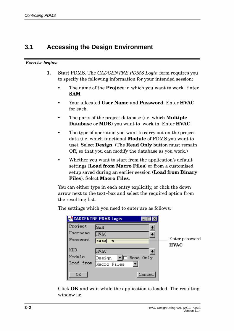
1. Start PDMS. The CADCENTRE PDMS Login form requires youto specify the following information for your intended session:
S The name of the Project in which you want to work. EnterSAM.
S Your allocated User Name and Password. Enter HVACfor each.
S The parts of the project database (i.e. whichMultipleDatabase orMDB) you want to work in. Enter HVAC.
S The type of operation you want to carry out on the projectdata (i.e. which functionalModule of PDMS you want touse). Select Design. (The Read Only button must remainOff, so that you can modify the database as you work.)
S Whether you want to start from the application’s defaultsettings (Load from Macro Files) or from a customisedsetup saved during an earlier session (Load from BinaryFiles). SelectMacro Files.
You can either type in each entry explicitly, or click the downarrow next to the text--box and select the required option fromthe resulting list.
The settings which you need to enter are as follows:
Enter passwordHVAC
Click OK and wait while the application is loaded. The resultingwindow is:

Controlling PDMS
3--3HVAC Design Using VANTAGE PDMSVersion 11.4
3D View Tool Bar
Main Menu Bar
Members List3D Graphical View
Main Tool Bar
Status Bar
D Main Menu Bar � the area from which you select the principalcommands. The title bar of this window shows the current PDMSmodule and its sub--application (if relevant) in which you areworking; in this case, the General application of the Designmodule.
D Main Tool bar � provides short--cuts to some commonoperations and standard settings via icon buttons anddrop--down option lists.
D Members List � shows your current position in the databasehierarchy. You can move to a different point in the database byusing the left--hand mouse button to pick the required item inthe list.
D 3D Graphical View � the window in which you will display thedesign model graphically as it is being built up. Note that thiswindow has a pop--up menu, selectable by using the right-handmouse button, from which you will select options to control theways in which the model is represented. It also has its own toolbar, the 3D View Tool Bar.

Controlling PDMS
3--4 HVAC Design Using VANTAGE PDMSVersion 11.4
D Status Bar � displays information about the current status ofyour operations. It is located across the bottom of the mainwindow.
You can reposition or minimise these windows at any time by usingthe standard window management facilities provided by yourworkstation (but do not close them in this way).
3.2 Using the Mouse
You use the mouse to steer the graphics cursor around the screen andto select or ‘pick’ items by using the mouse buttons. The buttonsperform different tasks depending on the type of window, and theposition within the window, where the cursor is positioned. Theappearance of the cursor will change according to the type of displayitem that is underneath it.
The functions of the buttons are:
Left--Hand Button:The left--hand button is the main button for selecting items. On agraphical view, clicking the left--hand button with the cursor over adesign element results in that element becoming the currentelement (that is, the design item on which you want to carry out thenext operation). In a sequence ofmenus, dragging with the left--handbutton activates the command represented by the highlighted menuoption when the button is released. On a form, the effect depends onthe type of gadget that has been selected � see Section 3.6 for details.
Middle Button:The principal use of the middle mouse button in DESIGN is tomanipulate a graphical view.
Right--Hand Button:The principal use of the right--hand mouse button in DESIGN is toaccess the menu options specific to the graphical view window.
3.3 Using Menus
There can be three types of option in a pull--down or pop--up menu:

Controlling PDMS
3--5HVAC Design Using VANTAGE PDMSVersion 11.4
Options shown as plain text: selecting one of these initiates anaction immediately.
Options followed by three dots: selecting one of these displays aform on which to select options, enter data, etc.
Options followed by a triangular pointer: selecting one of thesedisplays a subsidiary menu giving a further range of options.
Throughout this guide, related selections from menus are shown inabbreviated form by using the > symbol as a separator. Thus, thesequence Utilities>Reports>Create means ‘select Utilities fromthe main menu bar, then select Reports from the resultingpull--down menu, then move the cursor to the right and select Createfrom the resulting submenu’.
3.4 Using the Tool Bar Buttons
The tool bar is displayed immediately below the main menu bar in theapplication window. It contains a number of icon buttons which letyou carry out common tasks without searching for the options in themenus.
The actions of the buttons are explained in the on--line help. If youpause the cursor over a button, a tool--tip pop--up will remind you ofthe function of the button. To activate a button, simply click on it.
NOTE: The tool bar can be switched off, or displayed with largericons. To do so, select Settings>System from the mainmenu bar and then set the required options on the resultingSystem Settings form.
3.5 The Status Bar
The status bar (the Status Form on Unix systems) displays messagestelling you what actions the application is carrying out. You shouldlook at it frequently, especially if the system appears to be waiting foryou to do something, since it will always prompt you for any input oraction which is required to carry out the next step of your currentactivity.
CECE
Clashes...
Reports

Controlling PDMS
3--6 HVAC Design Using VANTAGE PDMSVersion 11.4
If the prompt lets you repeat a task an unspecified number of times,such as picking a selection of items using the cursor, you must pressthe Escape key (or click the Escape button on the Status Form )when you have finished to indicate that you are ready to move to thenext operation.
3.6 Using Forms and their Controls
Forms are used both to display information and to let you enter newdata. Forms typically comprise an arrangement of buttons of varioustypes, text--boxes, and scrollable lists. Input to a form is usuallyvia a combination of mouse and keyboard, the mouse being used toselect appropriate controls and the keyboard to enter data.
While you have access to a form, you may change a setting, return tothe initial values, accept and act on the current data, or cancel theform without applying any changes, according to the nature of theform.
This section describes how to use the principal types of gadget thatyou will see on the various forms.
3.6.1 Using Radio Buttons
Radio buttons are used to select one, and only one, from a group ofoptions. The selection is mutually exclusive, so that selecting oneoption deselects others in that group automatically.
They typically have the following appearance:
Radio button On
Radio button Off
To change the selected radio button in a group, click the requiredbutton.
3.6.2 Using Check Boxes (Toggle Buttons)
Check boxes (toggle buttons on Unix systems) are used to switch anoption between two states, typically On and Off. Unlike radio buttons,

Controlling PDMS
3--7HVAC Design Using VANTAGE PDMSVersion 11.4
they do not interact, so that you can select any combination to be Onat the same time.
They typically have the following appearance:
NT
Check box On
Check box Off
3.6.3 Using Text--Boxes
Text--boxes are the areas where you type in alphanumeric data suchas names or dimensions. A text--box will usually have a label to tellyou what to enter.
When you first open a form which contains text--boxes, the firsttext--box on the form will be current and a text editing cursor (avertical bar) will be displayed in the box. A text--box often contain adefault entry (e.g. unset) when first displayed. Some text--boxes willaccept only text or only numeric data, and entries with the wrongtype of data will not be accepted.
To enter data into a text--box:
D Click in the box to insert the text editing cursor.
D Type in the required data, editing any existing entry asnecessary. (You may need to delete the existing entry first.)
D When you have finished, confirm the entry by pressing theEnter (or Return) key. Any text--box with an unconfirmedsetting is highlighted by a yellow background.
3.6.4 Using Drop--Down Lists
Drop--down lists let you choose one option from a multiple selection.The list will usually have a label to tell you what you are setting andwill show the current selection.
They typically have the following appearance:
NT Drop--Down List
North
Controlling PDMS
3--8 HVAC Design Using VANTAGE PDMSVersion 11.4
To change the setting, click on the down arrow or button face to revealthe full list of available options, then pick the required option.
3.6.5 Using Scrollable Lists
A scrollable list is displayed as a vertical list of options within theform, with vertical and horizontal scroll bars along its sides. To selectan option, click on the line you want. The selected line will behighlighted.
Some scrollable lists let you make only a single selection, so thatselecting any option deselects all others automatically. Other lists letyou makemultiple selections, with all selected options highlightedsimultaneously. To deselect a highlighted option in a multiple--choicelist, click on it again (repeated clicks toggle a selection On and Off).
3.6.6 Actioning Form Inputs
Most forms include at least one control button which is used eitherto enter the command option represented by your current formsetting, to cancel any changes made to the form since you opened it,or to close the form.
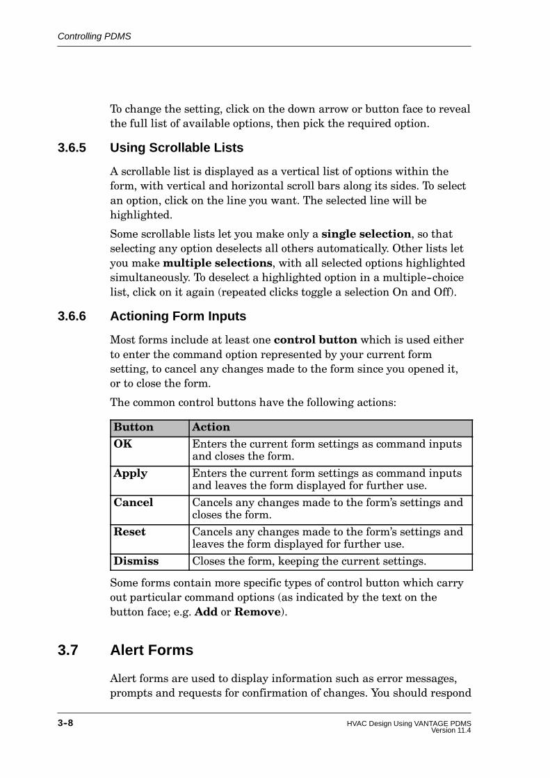
The common control buttons have the following actions:
Button ActionOK Enters the current form settings as command inputs
and closes the form.
Apply Enters the current form settings as command inputsand leaves the form displayed for further use.
Cancel Cancels any changes made to the form’s settings andcloses the form.
Reset Cancels any changes made to the form’s settings andleaves the form displayed for further use.
Dismiss Closes the form, keeping the current settings.
Some forms contain more specific types of control button which carryout particular command options (as indicated by the text on thebutton face; e.g. Add or Remove).
3.7 Alert Forms
Alert forms are used to display information such as error messages,prompts and requests for confirmation of changes. You should respond

Controlling PDMS
3--9HVAC Design Using VANTAGE PDMSVersion 11.4
by carrying out the task prompted for or by clicking on the controlbuttons on the form (usually an OK or Cancel button).
3.8 Accessing On--Line Help
Most bar menus end with a Help option. Where available, on--linehelp gives detailed instructions on the use of the forms and menus viawhich you control each application.
The Help option gives you the following choices from its sub--menu:
Help>on Context
This gives you help on any window currently visible in the display.When you select this option, the cursor changes to a question mark(?). Move the question mark into the window on which you want helpand click the left--hand mouse button.
Help>Contents
This displays the Help window so that you can find the required topicfrom the hierarchical contents list.
Help>Index
This displays the Help window so that you can find all topics relevantto a selected keyword.
Help>About
This displays information about the current operating system on yourcomputer and about the versions of PDMS and its applications towhich you have access.
Pressing the F1 key at any time will display the help topic for thecurrently active window (equivalent to Help on Context for thecurrent window).
Exercise continues:
2. Experiment with each of the Help options until you understandthe search and navigation facilities for finding specific items ofinformation. Use the Help>on Context option to read the helptexts for any forms which you can currently see on your screen.

Controlling PDMS
3--10 HVAC Design Using VANTAGE PDMSVersion 11.4
3. When you are ready to continue, close any forms which you havebeen experimenting with as follows:
D If a form has a Dismiss button, click this button.
D If a form has its own menu bar, select Control>Close from thatmenu.
D Close any Help windows which are displayed by double--clicking inthe control box in the top left--hand corner of each window.Alternatively, select File>Exit from the Help window’s menu bar.
Do not close theMembers List or the 3D View windows, as youwill use these in the next parts of the exercise.
You are recommended to make full use of the on--line help facilitieswhenever you want clarification of any operations during the latersteps of the exercise.

4--1HVAC Design Using VANTAGE PDMSVersion 11.3
4 How Design Data is Stored and Viewed
In this chapter we will look at the ways in which design data is storedby PDMS and how the design model represented by this data can beviewed and manipulated.
Although this guide is about the design of HVAC ducting networks, inpractice you will usually route your ductwork with reference to somepredefined design items such as the framework, floors and ceilings ofa building. To show how this is done, we will consider briefly howthese other items might be defined in PDMS, as well as looking athow we route sequences of HVAC components and ducting withinthem.
Before we start to create HVAC design data, it is important that youknow how such data is stored and accessed in the PDMS databases,so that you will understand the terminology which you will encounterduring the design process. This is explained in the following section.
4.1 How PDMS Stores Design Data
All PDMS data is stored in a hierarchic or ‘tree’ format (similar to theway in which you use a hierarchy of directories and subdirectories toaccess your computer files). In the case of a PDMS Design database,the topmost data level is called theWorld (usually represented by thesymbolic name /*), below which are the administrative sublevels Siteand Zone.
The names used to identify database levels below Zone depend on thespecific engineering discipline for which the data is used. In the caseof HVAC design data, the lower administrative levels (and theirPDMS abbreviations) are HVAC and Branch (BRAN). Each HVACcan represent any portion of the overall ducting network. Each

How Design Data is Stored and Viewed
4--2 HVAC Design Using VANTAGE PDMSVersion 11.4
Branch within an HVAC represents a single sequence of componentsrunning between two, and only two, points known as the BranchHead and the Branch Tail. Each Branch represents items with acommon specification. The data which defines the physical design ofthe individual HVAC components is held below Branch level.
To represent the parts of the building within which we will route ourductwork, we use a different administrative level below Zone, namelythe Structure (STRU) level. The physical design of each part of thebuilding is represented by a set of basic 3D shapes known asPrimitives, held below Structure level (in the examples which followwe use only rectangular BOX primitives). Holes through items arerepresented by Negative Primitives (we use negative boxes, NBOXprimitives, where HVAC ducting is to pass through the walls).
Together, these hierarchic levels give the following overall format:
WORLD (/*)
SITE
ZONE
HVAC
BRANCH
Design data defining individual HVAC components
SITE
ZONE
STRUCTURE
Design data defining structural shapes
(straights, bends, offsets, threeway connectors, inline plant etc.)
(primitives and negative primitives)
All data is represented in the database thus:
D Each identifiable item of data is known as a PDMS element.
D Each element has a number of associated pieces of informationwhich, together, completely define its properties. These areknown as its attributes.
Every element is identified within the database structure by anautomatically--allocated reference number and, optionally, by auser--specified name. Additional items of information about anelement which could be stored as attribute settings include:
D Its typeD Its physical dimensions and technical specificationsD Its physical location and orientation in the design model

How Design Data is Stored and Viewed
4--3HVAC Design Using VANTAGE PDMSVersion 11.3
Some attribute settings must be defined by you when you create anew element, others will be defined automatically by PDMS.
The vertical link between two elements on adjacent levels of thedatabase hierarchy is defined as an owner--member relationship.The element on the upper level is the owner of those elementsdirectly linked below it. The lower level elements aremembers oftheir owning element. Each element can have many members, but itcan have only one owner.
When you are modifying a database (for example, when you arecreating new elements or changing the settings of their attributes),you can consider yourself to be positioned at a specific point withinthe hierarchy. The element at this location is called the currentelement (often abbreviated to CE).
You can navigate from any element to any other, thereby changing thecurrent element, by following the owner--member links up and downthe hierarchy.
In many cases, commands which you give for modifying the attributesof an element will assume that the changes are to be applied to thecurrent element unless you specify otherwise, so you must understandthis concept and always be aware of your current position in thedatabase hierarchy. TheMembers List (see Section 3.1) will alwaysshow you this information.
4.2 The Existing Design Hierarchy
In order to provide a starting point for the HVAC routing exercise, thesample database supplied already contains a simplifiedrepresentation of a building built up from sets of box shapes. In thisand the following section, we will look at this model in terms of itshierarchic structure and its 3D representation.

How Design Data is Stored and Viewed
4--4 HVAC Design Using VANTAGE PDMSVersion 11.4
Exercise continues:
4. Look at theMembers List, which shows the element hierarchywhich currently exists in the /HVAC multiple database.
Navigate up and down the hierarchy by clicking on the variouselements. You will see that there are already a Site and a Zone(with the names /HVACSITE and /HVACZONE, respectively),and that the Zone owns several Structures (STRUs). EachStructure (whose name gives a clue to its function) owns one ormore Boxes representing the various parts of the building.
(If you or other users have accessed this database before, the listmay contain other elements as well.)
4.3 Viewing the Design
In order to see what the design model looks like, and to enable us toidentify design items by simply pointing to them rather than bynavigating to them in theMembers List, we will display the existingdesign in a 3D View window and learn how to manipulate thisdisplay.
First we will set the scale of the view, then the viewing direction, andfinally we will specify which design elements we want to see and howwe want them to be represented.

How Design Data is Stored and Viewed
4--5HVAC Design Using VANTAGE PDMSVersion 11.3
4.3.1 Defining What Appears in the View
Exercise continues:
5. We want to see the whole of the building within which we aregoing to route our HVAC network, so navigate to the zone/HVACZONE in the Members List. Position the cursor in the 3DView window and hold down the right--hand mouse button todisplay the pop--up menu. Select Limits>CE (CE means CurrentElement). This adjusts the scale of the view automatically suchthat it corresponds to a volume just large enough to hold thechosen element(s); in this case, the Zone.
6. Again using the 3D View menu, select Iso>Three to set anisometric view direction.
7. If the graphical view background colour is not already black,select Settings>Background from the 3D View menu (if thisoption does not appear on the menu, select Settings>LongMenus and try again). Select Black from the resultingBackground Colour palette.
8. Select either Display>Drawlist from the main menu bar orControl>Drawlist from theMembers List menu bar. Thenormal Members List will be replaced by an extended versionentitled Members+Draw. This lets you build up a list of allelements which you want to display, as shown in the Drawlistscrollable list in the lower part of the form. If this list alreadycontains entries, click the All button in the Remove FromDrawlist section to empty the list (the view should now show nodesign elements).
In order to make it easier to distinguish between the variousparts of the building, we will display the set of boxes representedby each Structure in a different colour.
In the Add To Drawlist section of the form, click the Colourbutton and select Black from the resulting Drawlist ElementAdd Colour form. Notice how the pane next to the Colourbutton changes to show the currently selected colour. Now pickthe Structure /HVACFLOOR in the list in the upper part of theform and click the Add CE button in the Add To Drawlistsection to enter the selection into the Drawlist, thus:

How Design Data is Stored and Viewed
4--6 HVAC Design Using VANTAGE PDMSVersion 11.4
Click to additem toDrawlist
Select item toadd toDrawlist
Select colour inwhich item is to bedisplayed
Now use the same sequence to add /HVACWALLS in Blue,/HVACCOLS (columns) in Green, and /HVACBEAMS inCyan. Note that you do not add /HVACROOF, so that you cansee inside the building as you create the HVAC components inthe next chapter.
When you have finished, set the current colour to Grey, ready todisplay the HVAC components which we will create in the nextchapter.
Select Control>Close from the menu on theMembers+Drawform to remove the form from the screen and replace it by thenormal Members List. Notice how the colour palette is dismissedautomatically when you dismiss theMembers+Draw form.

How Design Data is Stored and Viewed
4--7HVAC Design Using VANTAGE PDMSVersion 11.3
You should now see the building representation, something likethis:
Verticalslider
Horizontal sliderStatus line showing view direction, manipulation mode etc.
Pickmodeprompt
NOTE: If the horizontal and vertical sliders are not visible, selectSettings>Borders from the 3D View menu to display them.
9. Observe the effect of selecting different view directions from theLook and Iso menu options provided by the 3D View menu.Revert to Iso>Three when you have finished.
4.3.2 Manipulating the Displayed View
You can manipulate the displayed model view in a number of ways.The three basic operations which we will look at here are:
D Rotate the view
D Pan the view across the display area
D Zoom in or out to magnify or reduce the view
The current manipulation mode is shown in the status line at thebottom of the 3D View window (it is set to Rotate in the precedingillustration).
To change the view manipulation mode, look at the View Controloptions on the pop--up menu. The options of interest are Zoom, Panand Rotate.

How Design Data is Stored and Viewed
4--8 HVAC Design Using VANTAGE PDMSVersion 11.4
Alternatively, you can change the manipulation mode by pressing oneof the function keys, or by using the 3D View tool bar buttons, thus:
F2 or selects Zoom mode
F3 or selects Pan mode
F5 or selects Rotate mode
Exercise continues:
10. Select Rotate mode. Position the cursor in the view area andhold down the middle mouse button, then move the mouse slowlyfrom side to side while watching the effect on the displayedmodel. The initial direction of movement determines how theview appears to rotate; starting with a left or right movementcauses the observer’s eye--point to move across the view. Nowrelease the mouse button, hold it down again and move themouse away from you and towards you; this time the observer’seye--point should appear to rotate up and down around themodel.
Repeat the rotation operations while holding down the Controlkey. Note that the word Fast appears in the status line and thatthe rate of rotation is increased. Now repeat the same actions,but this time hold down the Shift key. Note that the word Slowappears in the status line and that the rate of rotation isdecreased.
For an alternative way of rotating the model, try dragging thehorizontal and vertical sliders to new positions along the viewborders. You can rotate the model in this way at any time,regardless of the current manipulation mode.
11. Select Pan mode. Position the cursor in the view area and holddown the middle mouse button, then move the mouse slowly indifferent directions. Note that it is the observer’s eye--pointwhich follows the mouse movement (while the viewing directionremains unchanged), so that the displayed model appears tomove in the opposite direction to the mouse; in effect, you movethe mouse towards that part of the view which you want to see.
Repeat the pan operations while holding down first the Controlkey (to increase the panning speed) and then the Shift key (todecrease the panning speed).

How Design Data is Stored and Viewed
4--9HVAC Design Using VANTAGE PDMSVersion 11.3
12. Select Zoom mode. Position the cursor in the view area and holddown the middle mouse button, then move the mouse slowly upand down. Moving the mouse away from you (up) zooms in,effectively magnifying the view; moving the mouse towards you(down) zooms out, effectively reducing the view. Note that theseoperations work by changing the viewing angle (like changingthe focal length of a camera lens); they do not change theobserver’s eye--point or the view direction.
Repeat the zoom operations while holding down first theControl key and then the Shift key.
13. Position the cursor at the top of one of the corner columns andclick (do not hold down) the middle mouse button. Notice howthe view changes so that the picked point is now at the centre ofthe view. Whenever you click the middle button, whatever thecurrent manipulation mode, you reset the centre of interest.Switch to Zoom mode (if not already selected), set the centre ofinterest to the grille in the front wall, then zoom in for aclose--up view of the grille. You will find this a very usefultechnique when making small adjustments to the design.
14. To restore the original view when you have finished, check thatyour current element is /HVACZONE and reselect ISO>Threeand Limits>CE.
4.4 Saving the Current Design and Leaving YourDesign Session
Even though you have not yet made any changes to the designdatabase, this is a suitable point at which to demonstrate how to storethe current design at any stage of a PDMS design session and how torecord your screen layout so that you can start your next designsession in exactly the same state that you ended the current one.
Exercise continues:
15. To update the database so as to store the design model in itscurrent configuration, select Design>Save Work from the main

How Design Data is Stored and Viewed
4--10 HVAC Design Using VANTAGE PDMSVersion 11.4
menu bar or click the button. (It is wise to use this functionperiodically as you build up a design, so that you do not have tostart from the beginning in the event of loss of work due to anunforeseen interruption, such as a power failure.)
16. To save your current screen layout and display settings, so thatnext time you use the application you can rapidly restart fromwhere you interrupted your design session, select Display>Save>Forms & Display from the main menu bar.
17. To leave your current PDMS design session and return to theoperating system, select Design>Exit from the main menu bar.If you had made any changes since your last Save Workoperation, you would be asked if you wanted to save them; in thepresent situation, you will just be asked to confirm that youwant to leave PDMS.
In the next chapter, we will install a simple HVAC ducting networkinto the building model.
5--1HVAC Design Using VANTAGE PDMSVersion 11.4
5 Routing a Sequence of HVACComponents
In this chapter we will route an HVAC network between the grilles inthe building walls, positioning a selection of HVAC componentswithin the ducting runs. Before we do so, we will expand the earlierinformation about how the design data is stored and accessed inPDMS.
5.1 HVAC Component Representation in the Catalogue
Each HVAC component is represented in the PDMS catalogue bythree types of data:
D The physical shape of the component is defined by a set ofgeometric primitives.
D In order that the component can be manipulated and linked toadjacent HVAC items, all principal points needed to define itsposition, orientation and connectivity are identified byuniquely--numbered ‘tags’. These tags, which have both positionand direction, are called p--points. Each p--point is identified bya number of the format P0, P1, P2 etc., while the principal inletand outlet points for the logical flow direction through thecomponent are also identified as p--arrive (PA) and p--leave(PL). P0 always represents the component’s origin position,while P1 is the same as p--arrive and P2 is the same as p--leave.
D The settings of all variables needed to distinguish a componentfrom others with the same geometry and p--point sets are definedby parameters. The values of these are defined to suit thespecific design requirements.

Routing a Sequence of HVAC Components
5--2 HVAC Design Using VANTAGE PDMSVersion 11.4
For example, a rectangular three--way component (or branchconnector) might be represented in the PDMS catalogue as follows:
P2P0
P3
P1 (P--arrive or PA)
(P--leave or PL)
(origin)(branch connection)
where the two curved duct sections form the component’s geometryset and the four p--points form its point set (the fourth p--point, P3,lets you control the direction of the branch connection arm when youincorporate the component into your design). The dimensions of thecomponent, and other constructional details, are represented in thecatalogue by parameters whose values are set to suit the designrequirements.
5.2 Restoring Your PDMS Session and Starting theHVAC Application
Exercise continues:
18. Restart PDMS and enter the Design Constructor module (as inStep 1), but this time set the Load From button on theCADCENTRE PDMS Login form to User’s Binary. Whenloading is complete, your screen should look the same as it didwhen you saved the layout in Step 16.
(If you intend to continue from where you finish at the end ofany PDMS session, it is always quicker to use the Display>Save> Forms & Display option so that you can reload thebinary files in this way, rather than to reload the applicationsfrom their source macros each time you use the Design module.You can revert to the most recently saved layout at any time byselecting Display> Restore> Forms & Display.)

Routing a Sequence of HVAC Components
5--3HVAC Design Using VANTAGE PDMSVersion 11.4
19. So far, we have been working in DESIGN’s ‘general’ applicationmode, where the menus and facilities available are common toall engineering design disciplines. We will now start the HVAC--specific application, which tailors the functionality of theDESIGN module to suit the explicit needs of the HVAC designer.From the General Application menu bar, pick Design>HVACDesigner to load the HVAC application.
When loading is complete, the application window will includesome extra options, thus:
20. Rather than having to use these menu options for everyoperation, all of the principal functions for creating, positioning,orientating and connecting HVAC elements are available fromwithin a single form. To display this form, select Create>HVAC. The resulting form, called the Heating, Ventilation, AirConditioning (HVAC) form (which we will refer to simply as theHVAC form), may be viewed in either of two formats: a briefversion or a full version (as shown in the following illustration).
The brief version uses drop--down lists to show the elementsavailable for selection when you are creating a design, whereasthe full version uses scrollable lists for this purpose (and alsooffers some more complex positioning options).
The full version is recommended while you are learning to usethe application, but you may prefer to use the brief version ifyour screen is small or of low resolution. To switch betweenthem, select Control>Use Full/Brief Form from the HVACform’s menu.

Routing a Sequence of HVAC Components
5--4 HVAC Design Using VANTAGE PDMSVersion 11.4
Brief version Full version
21. To suit user preferences, depending on the level of experienceand the type of design work being undertaken, the appearanceand behaviour of the forms used for creating and modifyingHVAC components can be customised. To do so, select Control>Style Options from the HVAC form’s menu. On the resultingHVAC Form Style form, set all options to On except theOK/Cancel Forms button, like this:
These settings have the following effects:
D Show Local Views On will display a small 3D graphicalview showing the current component in its design context.
D Local Views Shade On will show local views incolour--shaded (as opposed to wireline) representation.

Routing a Sequence of HVAC Components
5--5HVAC Design Using VANTAGE PDMSVersion 11.4
D Show Pixmaps On will automatically display diagramsshowing component geometries to help you select itemsfrom the catalogue.
D Show Forms On will display a create/modify formautomatically when you add a new component to thedesign, so that you can adjust the default dimensionsand/or orientation as required.
D OK/Cancel Forms Off means that componentcreate/modify forms will have Apply/Dismiss buttons(instead of OK/Cancel buttons), so that they remainavailable for repeated use until dismissed explicitly.
These settings give you the maximum amount of help as youstart to learn about the application. You can change any of themwhen you wish, as you progress through the exercise.
5.3 Setting the Current Detailing Specification
When you select components from the HVAC catalogue, theirconstructional details are determined by the current detailingspecification. This setting is shown, and can be changed, by thedrop--down list immediately below the main menu bar and toolbar.When you first display the HVAC form, this specification is setautomatically to TUTORIAL, like this:
This specification gives access to a range of catalogue componentssuitable for use with this exercise. You could, if you wished, select adifferent specification for each HVAC Branch, but we will use thesame specification for the whole of the design exercise.

Routing a Sequence of HVAC Components
5--6 HVAC Design Using VANTAGE PDMSVersion 11.4
5.4 Creating Some Administrative Elements
Before we can create the individual components which will make upour HVAC network, we must first create the HVAC and Branchelements which govern their positions in the database hierarchy, asexplained in Section 4.1.
Exercise continues:
22. Check that your current element is the zone, /HVACZONE,below which the HVAC design data is to be stored. From theCategories list on the HVAC form, select PDMS Branches.From the Available Types list, select HVAC System Element.You will see a Create HVAC form.
In the HVAC Name text--box, enter HTESTHVAC. Click Applyto create the HVAC element, then Dismiss to remove the form.
23. With the Categories selection still set to PDMS Branches,selectMain Branch Element from the Available Types. Youwill see an HVAC Main Branch Element form.
Enter the Branch Name as HTESTB1.
The Specification is set automatically to the current detailingspecification (TUTORIAL). Leave this as it is.
Set the Branch Head Shape to Rect (rectangular).
In the Head Direction text--box, enter N (this will be thedirection looking along the ductwork run from the head positiontowards the first component).
Enter Duct width AA (the Arrive A dimension) as 1000 andDuct depth AB (the Arrive B dimension) as 500.
Use the Insulation Thickness option button to select 50 mm(this will add 50mm of insulation automatically to each surfaceof all components and ducting owned by the branch).
We will specify the position of the Branch Head by picking ap--point at the centre of the hole in the front wall of the building.To do so, use the Head Start drop--down list to select ID DesignPPoint and then click Apply. When prompted by the status barto ’Identify design ppoint’, use the cursor to pick P5 of the

Routing a Sequence of HVAC Components
5--7HVAC Design Using VANTAGE PDMSVersion 11.4
’negative box’ representing the hole in the wall. To find thecorrect p--point, zoom in close to the area of interest (see Step 13if you have forgotten how to do this) and position the cursor onthe edge of the box as you press and hold down the left--handmouse button; the p--points will appear as dots. Move the cursorover the centre of the southernmost face with the mouse buttonheld down. The status bar will show the identity of each p--pointas the cursor passes over it; release the button over P5.
Dismiss the HVAC Main Branch Element form.
That completes the creation and definition of the first branch withinwhich we will build up a sequence of HVAC components.
NOTE: The distinction between amain branch and a side branchin the PDMS Branches category is simply one ofconvenience; in PDMS terms they are the same type ofelement. A main branch requires that you position andorientate its head explicitly, whereas a side branch takes itshead position and orientation from a branch connectionpoint (P3) on an existing three--way component (see diagramin Section 5.1). We will use the latter facility later in theexercise.
5.5 Creating HVAC Components
It is usual to build up your HVAC design by adding componentssequentially, starting at the branch head, and positioning andorientating each component as you proceed. We will follow thismethod.
(For an advance look at the overall configuration which we will becreating in this chapter, see the diagram on page 5--16.)
Exercise continues:
24. The first component we will create is a rectangular straightwhich we will position outside the building, aligned with thehole in the wall at which we positioned the branch head, likethis:

Routing a Sequence of HVAC Components
5--8 HVAC Design Using VANTAGE PDMSVersion 11.4
NStraight will becreated here
It will then bemoved to here
Branch head is hereIt will be moved to here
NOTE: The diagrams used throughout this exercise are forillustrative purposes only and are not to scale.
Select Rectangular from the Categories list. Because we setShow Pixmaps to On in Step 21, the Available Types list willbe supplemented by a palette of diagrams showing what theavailable options look like. Click on the Straight diagram in thetop left--hand corner of the palette. (If you had chosen not todisplay the diagrams, you would select Straight from theAvailable Types list.) You will see a Rectangular Straight formwhich has data fields for all parameters needed to fully definethe component.
The initial data settings on these component definition forms aredetermined by a set of default values read from a file, so that youneed to enter only a minimum amount of data in most instances.To see what the parameters mean in terms of the component’sgeometry, click the Picture button on the form. You will see anHVAC Component form containing a dimensioned and annotateddiagram showing how the component is defined in the catalogue;compare the data fields on the Rectangular Straight form withthe diagram (see Appendix C for a full set of these diagrams).Wewill use the defaults, so select Control>Close to remove theHVAC Component form and then click Apply on the RectangularStraight form. Dismiss the Rectangular Straight form. Therectangular straight will be created and positioned with its PA at

Routing a Sequence of HVAC Components
5--9HVAC Design Using VANTAGE PDMSVersion 11.4
the branch head, so that it is inside the building (as shown inthe above diagram).
25. We must now move the straight to the required position. To doso, we will use the component manipulation features on theHVAC form. Look at the area labelled POSITION on the form.In the text--box next to theMove by button, enter the requireddisplacement; in this case, enter S5000D96. As soon as youpress Return to confirm the data, the straight will be moved.
26. To check that the straight is in the correct position, selectQuery>Position>Origin from the main menu bar. The positionwill be shown in an HVAC Command Output window. It shouldread: E 3048 mm S 5125 mm U 3300 mm.
27. We will now reposition the branch head so that it coincides withthe PA of the straight. To do this, look at the area labelledCONNECT on the HVAC form. Set the drop--down lists in thebottom row to read HVAC Branch Head to First Member.This connects (and therefore repositions) the head of the currentbranch to the PA of the first component in its members list,which is the straight (this is, of course, the only branch memberso far).
NOTE: We could have positioned the branch head here when wefirst created it (in Step 23), but this would have required usto calculate its coordinates explicitly. It is usually easiest, ashere, to position a new item relative to an existing designpoint and then to move it later.
28. The last operation will have made the branch (more precisely,the branch head) the current element. Each new component iscreated immediately after the current component in branch listorder, so before we create the second component in the branch,navigate to the straight by clicking on it in either theMembersList or the 3D View.
We will now position a fire damper where the ducting will passthrough the wall. Select Inline Plant Equipment from theCategories list and then select Rectangular Fire Damperfrom the displayed types. On the Rectangular Fire Damper form,name the component as required (say, FD1) and leave allparameter settings at their default values (click the Picturebutton to see their relevance). Notice that the local view at the

Routing a Sequence of HVAC Components
5--10 HVAC Design Using VANTAGE PDMSVersion 11.4
right--hand side of the Rectangular Fire Damper form shows theexisting straight (remember, we set Show Local Views to On inStep 21). Click Apply to create the fire damper.
29. When first created, the fire damper is positioned so that its PA iscoincident with the PL of the preceding straight. We will nowmove it so that it fits within the wall.
NFire dampercreated here
Fire dampermoved to here
In the POSITION area of the HVAC form, set the Throughoption button to ID Element. When prompted to identify anelement, pick any part of the southernmost wall. The firedamper will be moved forward along its axis (i.e. towards theNorth) until it lies in the plane of the wall. (You will not now beable to see the fire damper in the 3D View, since it will be hiddenwithin the negative box which represents the hole through thewall.)
Notice how the gap between the straight and the fire damper isfilled automatically by a length of implied ducting in the 3DView (implied ducting is not shown as an element in theMembers List). We will see how to replace implied ducting withcatalogue straights in a later stage of the exercise.
30. Change the 3D View direction to Look>Plan North, so that yousee a view similar to that illustrated in the preceding diagrams.
31. Create a Rectangular Square Bend with all default settingsexcept the Leave Direction. Set the latter toW, so that thebend orientation is as follows:

Routing a Sequence of HVAC Components
5--11HVAC Design Using VANTAGE PDMSVersion 11.4
N
PL ofbend
Note: Implied ducting shown by lightershading than the HVAC components in alldiagrams
OK the warning message; its significance will be explained inSection 5.6.
Notice that theMembers List now shows two new elements, onerepresenting the bend ducting, the other representing the set ofair deflectors within it (since it is a square bend requiringturning vanes; SPLR = Splitter). To see the deflectors inside thebend, switch the 3D View temporarily to wireline mode (use theSettings> Shaded option on the 3D View pop--up menu, orpress F8, to toggle between colour--shaded and wireline views).
5.6 How PDMS Represents Composite Components
It is important at this stage that you understand the concept ofhaving more than one PDMS element to represent a single HVACcomponent, since this means that you must be particularly carefulthat you are at the correct position in the branch members list whenyou want to refer to such a component. (You saw a message warningyou of this when you created the square bend containing thedeflectors.)
If you navigate to the square bend simply by picking it with thecursor, your current element will most likely be the outer ducting. The‘subcomponent’ which completes the item’s representation, namely thedeflector set, comes after the bend in the branch members list. Youmust therefore navigate to the element representing the deflectorsbefore you create another component which is to follow the bend inthe branch order.

Routing a Sequence of HVAC Components
5--12 HVAC Design Using VANTAGE PDMSVersion 11.4
Branch Members:. . .
previous componentbend ducting (BEND)deflector set (SPLR)
next component. . .
PL
PA
(We will see further examples of composite components andsubcomponents when we add stiffening flanges and access panels toour HVAC ductwork in the next chapter.)
5.7 Creating HVAC Components (Continued)
Exercise continues:
32. With the square bend’s deflector set as your current element,create a Rectangular Radiused Bend. Set its Inside Radiusto 100 and check that its Leave Direction is N.
Position the new bend in the plane of the westernmost wall byusing POSITION Through ID Element on the HVAC form andpicking either the wall or, if still using a plan view, the beamabove it.
Now move the bend to fit just inside the wall, and downwards sothat the ducting leaving it will pass under the beam across thebuilding roof, by using POSITION Move by E800D150. Theresult should be:
N
Duct to passunder beam
Broken line here showscomponents are misaligned

Routing a Sequence of HVAC Components
5--13HVAC Design Using VANTAGE PDMSVersion 11.4
33. Since we have moved the radiused bend downwards, its inlet(PA) is not vertically aligned with the outlet (PL) of thepreceding component. This is indicated in the 3D View by abroken line between the components (rather than impliedducting). To compensate for this, we will now insert a mitredoffset section between the two components.
Remember that the new component will always be addedimmediately after the current element, so navigate back to theprevious bend (or, more accurately, the deflector set of the squarebend). Then create a Rectangular Mitred Offset.
In order to calculate the length and correct amount of offsetneeded to fit the new component into its available space, we willuse a very powerful facility which does this automatically.Simply click the Fit button on the Rectangular Mitred Offsetform. The calculated data will be entered into the parameterdata fields: note, for example, that the A Offset is now set to150.
When you have completed the creation, zoom in close to themitred offset and view it from different angles to see how it hasbeen adjusted to fit between the two bends.
34. Navigate to the last component in the branch (the radiusedbend). Create a second radiused bend with the default InsideRadius (0.5 means 0.5 x duct width) and with its LeaveDirection East, in the following position:
N
New bendhere
(this beam willbe used as a ref-erence in Step35)

Routing a Sequence of HVAC Components
5--14 HVAC Design Using VANTAGE PDMSVersion 11.4
First position the bend in the plane of the northernmost wall(using Through ID Element and then picking the wall or beamabove it); then move it South by 1500 mm (usingMove byS1500).
35. The next item which we want to add is a circular section silencer,but in order to fit this, we must first insert a square--to--roundtransformation piece.
From the Categories list select Transformations, then fromthe Available Types select Square to Round. Enter the DuctDiameter as 750. Position the transformation piece in line withthe first beam reached in the branch--creation direction, shownstriped in the preceding diagram, then move it a further 300 mmEast.
Now select the Inline Plant Equipment component categoryand create a Circular Silencer. Name the item SILE1 and setthe Outer Diameter to 950.
36. We will now add another transformation piece to revert back torectangular ducting. Instead of specifying this from firstprinciples, we will create a copy of the existing transformationpiece and reverse it to achieve the desired round--to--squareresult.
On the HVAC form, click the Create Copy ID button. Whenprompted, pick the square--to--round transformation which youwant to copy. On the Square to Round Transformation form, setthe Flip Circ/Rect option to Yes; this interchanges the PA andPL points so as to reverse the component’s direction. When youcomplete the creation operation, the HVAC layout should looklike this:

Routing a Sequence of HVAC Components
5--15HVAC Design Using VANTAGE PDMSVersion 11.4
N
Squareto round
Round tosquare
Circularsilencer
37. The next item to be added will be a threeway component, so thatwe can connect another branch into our existing branch later inthe exercise. From the Rectangular category, create a SquareThreeway with both the Duct Width LA (leave A dimension)and Second Width (for the branch connection) set to 800 andwith the Leave Direction set to S.
Move the threeway component along the branch axis to achieve agap between it and the preceding component (the round--to--square transformation) of 1500 mm. To do so, enter 1500 in thetext--box next to the Distance button on the HVAC form. (Notethat this operation lets you specify the required result, namelythe gap between the PL of one component and the PA of the next,rather than having to calculate the movement required toachieve it.)
To check that the gap is correct, navigate back to theround--to--square transformation and select Query>Gap tonext from the main menu bar.
38. Return to the square threeway component and create aRectangular Radiused Bend with default dimensions andwith its Leave Direction set to East. Align the bend with thehole in the easternmost wall by using the Through ID Elementoption. Note that the current branch direction (i.e. the PLdirection of the previous component) was changed to South bythe threeway item, so the bend will move South until it isaligned with the picked element.

Routing a Sequence of HVAC Components
5--16 HVAC Design Using VANTAGE PDMSVersion 11.4
39. Create a Rectangular Fire Damper (like the one we createdand positioned in Steps 28 and 29), name it FD2, and position itthrough the hole in the easternmost wall.
40. Finally, to complete the branch definition, connect the BranchTail to the fire damper (i.e. to the Last Member of the branch).(This uses the same method that we used to connect the branchhead in Step 27.)
The final HVAC configuration should be as follows:
N
Branchhead
Branchtail
straight
square bend (inc.deflector vanes)
firedamper
verticaloffset
radiusedbend
radiusedbend
radiusedbend
firedamper
squareto
round
roundto
square
circularsilencer
threewayconnector
1500
unconnected P3ready to attach aside branch
41. Save your design changes.
That completes the creation of our main branch. In the next chapter,we will add some side branches and demonstrate a convenient utilityfor representing ceiling tiles which incorporate ventilation grilles. Wewill also replace all of the implied ducting with appropriate standardstraights.

6--1HVAC Design Using VANTAGE PDMSVersion 11.4
6 Adding to the HVAC Model
In the preceding chapter we created a sequence of HVAC componentsto form our main branch. In this chapter we will extend this model byadding some side branches.
We will begin by using some facilities for setting out a working gridand positioning ceiling tiles within it, so that we can then use thesetiles as references for positioning HVAC grilles.
6.1 The Grid/Tiling Utility
With reference to our existing design model, the next part of theHVAC ducting network which we are going to design will feed twoceiling grilles above the small room in the northeast corner of thebuilding. In order to position these grilles, we will use a facility whichlets you set out a horizontal grid and a ceiling tile layout based on aspecified datum point.
The grid/tiling utility is used in three stages:
1) Specify a setting--out point (S.O.P.) to represent the datumfrom which grid line positions are to be calculated.
2) Create grid lines at specified intervals, referenced from theS.O.P., in a horizontal plane.
3) Add tiles at specified positions in the plane of the grid.
Exercise continues:
42. If your screen is getting too full, you can temporarily close theHVAC form (Control>Close from its menu bar), since we willnot need to use it for the next few steps in the exercise. Navigateto the zone which owns the design model, namely /HVACZONE.The grid/tiles will be created below this hierarchic level.

Adding to the HVAC Model
6--2 HVAC Design Using VANTAGE PDMSVersion 11.4
43. From the main menu bar, select Utilities>HVAC Tiles/GridLayout>Setting Out Point. You will see an HVAC Grid SettingOut Point form.
Enter the S.O.P. Name as HTESTSOP1 and enter the SettingOut Point Height as 2700 (which is the elevation of the ceilingin which we will eventually position the grilles).
Click OK on the HVAC Grid Setting Out Point form. You will beprompted to pick the S.O.P. position using the cursor in a planview. We actually want to position the S.O.P. at the centre of theroom’s ceiling, which has the coordinates E15000 N9000 U2700.Rather than trying to pick this point precisely, pick any point inthe ceiling plane to create the S.O.P., then move it to the exactposition required. To do the latter, select Position>Explicitly(AT) from the main menu and enter the coordinates on theExplicit Position form (ignore the Positioning Control form). TheS.O.P. is represented by a DISH element in the PDMS hierarchy;it will appear in the 3D View as a small sphere.
44. We will next define a horizontal reference grid through theS.O.P. datum point (i.e. a grid in the plane of the ceiling), withthe grid lines spaced out from the S.O.P. in both directions.
Select Utilities>HVAC Tiles/Grid Layout>Grid from S.O.P.You will see an HVAC Layout Grid from SOP form.
Leave the East/West and North/South Grid Spacingseparations set to the default of 600.
Click OK. You might be prompted to identify the S.O.P. fromwhich the grid line positions will be calculated (unless it isalready the current element): if so, pick the S.O.P. which youhave just created. You must now define the horizontalrectangular area which represents the grid boundaries. You willbe prompted to pick first the South--West corner and then theNorth--East corner in a plan view. Pick the correspondingcorners of the room (i.e. the intersections of the beams at thesecorners).
Since our room is 6000 x 6000 mm, the 600 mm grid line spacingwill give us 10 grid squares in each direction within the ceilingarea, like this:

Adding to the HVAC Model
6--3HVAC Design Using VANTAGE PDMSVersion 11.4
N
= S.O.P.
Pick SWcorner first
Pick NEcornersecond
= Tiles tobe added
NOTE: If the room were not rectangular, you could build up anoverall grid by using abutting rectangles based on separatesetting--out points.
45. To complete this part of the exercise, we will create two tiles inthe ceiling grid where we want to install HVAC grilles (as shownby the shaded and striped grid squares in the precedingdiagram).
Select Utilities>HVAC Tiles/Grid Layout>Apply Tiles inGrid. You will see an HVAC Apply Tiles in Grid form.
Leave the East/West and North/South Tile Width dimensionsset to the default of 600. (They do not have to be the same size asthe grid squares, but will usually be so in practice.)
Click OK. You might be prompted to identify the S.O.P. whosegrid will be used to position the tiles. Even though there is onlyone, pick the S.O.P. to confirm your intentions.
You will now be prompted to identify the locations at which youwant to insert tiles. Pick the grid squares marked and inthe preceding diagram (the picked points snap to the nearesthalf tile, so you don’t need to be too precise). Then press theEscape key to indicate that you have finished adding tiles.

Adding to the HVAC Model
6--4 HVAC Design Using VANTAGE PDMSVersion 11.4
6.2 Creating Some Side Branches
We next want to create a side branch which runs from a take--offpoint on the main branch and which passes between the tile positions.We will then add two more side branches running from points on thefirst side branch to the tile positions (remember that you need aseparate branch for each length of ducting between two points).
We will complete the network by adding a fourth side branch, leadingto an angled outlet mesh, from the unconnected arm of the squarethreeway component.
Before we can create our first side branch, we must insert a suitableconnector into the main branch so that we have a point to which wecan connect the side branch head.
Exercise continues:
46. Navigate to the existing threeway item. We will insert anotherbranch connector immediately after it in the branch sequence.
Redisplay the HVAC form (Create>HVAC) if you dismissed itearlier and, from the Branch Connectors category, create aFlat Oval ‘A’ Boot component.
Set the Boot Width to 610, the Boot Depth to 152, the BOffset to 100, and the Boot Direction to E.
We want the oval ducting to pass along the centreline of theceiling, so position the current component so that its outlet isaligned with the S.O.P. datum at the ceiling’s centre (using theThrough ID Element facility on the HVAC form), thus:

Adding to the HVAC Model
6--5HVAC Design Using VANTAGE PDMSVersion 11.4
N
P3 of bootconnectoraligned withS.O.P.
Boot connectorwith flat oval sideoutlet
P3
P3
47. From the PDMS Branches category, create a Side Branch (offmain).
Enter the Branch Name as HTESTB1.1 (showing that it is aside branch of main branch HTESTB1) and set its InsulationThickness to 50 mm. Leave the Specification option buttonset to the current default; that is, to the same specification as themain branch.
Since you are creating a side branch, it is assumed that you willconnect its head to a free P3 point on an existing component. Setthe Connect Head to option button to Branch Connector toshow the type of component to which this connection will bemade. Click Apply. When prompted, pick the flat oval bootconnector. (Note that you can pick any part of the component;the new branch head will always be connected to its P3 point.)
48. As the first member of the new side branch, create a Flat OvalStraight with itsWidth Direction set to N.
49. We are now going to create two circular boot connectors fromwhich to route outlets to the two tile positions. We are going tocreate these and position them before we create the straight towhich they will be connected, so that the boots can be positionedrelative to the tiles and the length of the straight can then beadjusted to suit the boot positions.

Adding to the HVAC Model
6--6 HVAC Design Using VANTAGE PDMSVersion 11.4
With the oval straight as the current element, create a CircularBoot from the Branch Connectors category. Set the BootDiameter to 150 and the Inner Extension to 76. Set Distancefrom Leave to 100 and leave Boot Direction as N. This bootwill be positioned 100 mm back from the PL of the straight onwhich it will be mounted (which is only implied at this stage).Now move the boot so that it is aligned through thenorthernmost tile (shown as in the diagrams).
Create a second Circular Boot with Boot Diameter 150 andInner Extension 76, but this time set Distance from Leave to700 and Boot Direction to S. This Distance from Leavedimension positions the boot 700 mm back from the PL of theprevious boot. Since the previous boot was set back 100 mm fromits PL, the difference between the boot positions corresponds tothe 600 mm offset between the two tile positions. The result is asfollows:
N
100
700
ovalboot
first circular boot
second circular boot
PLs of bothcircular bootsare here
mainbranch
sidebranch
straight
tile
tile
50. We will now replace the implied ducting between the circularboots with a straight component. Because the boots aresubcomponents, as defined in Section 5.6, you must firstnavigate back two positions in the Members List to the existingstraight in this side branch. Now create a second Flat OvalStraight and use the Fit button to achieve the required lengthbetween the PL of the first straight and the PLs of the circularboots. (The calculated Length should be shown as 2525.)
51. To complete this first side branch, we will add a cap to close theend of the last straight. Navigate to the last component in the

Adding to the HVAC Model
6--7HVAC Design Using VANTAGE PDMSVersion 11.4
Members List (i.e. the southernmost circular boot) and create aFlat Oval Cap End. (Remember that the PL of this boot is asshown in the preceding diagram, not within the boot volumeitself, so that the cap should be positioned correctly and willappear in the correct list order.) Finally, connect the BranchTail to the Last Member of the branch (i.e. the cap).
52. Our second side branch will run from the northermost circularboot to a grille in the adjacent tile. Navigate to the first sidebranch (/HTESTB1.1) and create a new side branch namedHTESTB1.1.1 with 50 mm insulation thickness. Connect thehead of the new side branch to the circular boot connector.
53. Create a Circular Straight with Length set to 750. To seewhat types of leave joint are available, click the Choose buttonnext to the Leajoint field. From the resulting Choose Joint form,selectMale Socket & Spigot Joint and click OK. TheLeajoint field will be updated to showMALE.
54. Create a Circular Internal Damper with default settings.
55. Create a Circular Flexible Bend with its Leave Directionset to D (down). Position the bend so that it is aligned throughthe appropriate tile. (We will come back to this bend and adjustits dimensions to fit later.)
56. From the Transformations category, create a Circular toRectangular Spigot Box. Set the following parameters: DuctWidth LA = 300; Duct Depth LB = 300; Rectangular BoxHeight = 75; Circular Extension = 50; Circular Joint =MALE.
57. From the Inline Plant Equipment category, create aRectangular Grille In Line. Set the parameters as follows:Name = GRIL1; End Width = 400; End Depth = 400; GrilleLength = 50; ‘A’ Extension = 0.
We want the grille to fit within the tile volume, so set thePosition At option button on the HVAC form to ID Elementand, when prompted, pick the tile. The origin of the grille will bepositioned at the origin of the tile.
(At this stage the PL of the spigot box and the PA of the grillewill have become misaligned, so you will see a broken linebetween them rather than a length of implied ducting.)

Adding to the HVAC Model
6--8 HVAC Design Using VANTAGE PDMSVersion 11.4
58. Having positioned the grille correctly, we will now go back alongthe current side branch and adjust the other components to fit.
First, position the spigot box directly on top of the grille. To doso, navigate to the spigot box (PLEN = Plenum in theMembersList) and select Position At Next from the HVAC form’spositioning options.
Now adjust the dimensions of the flexible bend so that it fitscorrectly between the internal damper (at its PA) and the spigotbox (at its PL). To do so, navigate to the flexible bend and clicktheModify CE button on the HVAC form. This will redisplaythe Circular Flexible Bend form, but note that the option buttonat the top of the form is now set toModify rather than Create.Click the Fit button on this form to recalculate the dimensionsnecessary for a correct fit. (The calculated Arrive Extensionshould be set to 120 and the Leave Extension to 225.)
59. Complete the definition of the side branch by connecting its tailto the grille. The side branch /HTESTB1.1.1 should now looklike this (looking towards the West):
cross--section ofoval side branch/HTESTB1.1 circular boot
connector
circular straight
fire damperinside straight
flexiblebend
spigotbox
grille
Head
Tail
60. Repeat the sequence described in Steps 52 to 59 to create asimilar side branch, named /HTESTB1.1.2, from the secondcircular boot to a grille (/GRIL2) positioned in the other tile.(Remember to navigate up to the level of branch /HTESTB1.1first.)
The overall layout of the HVAC ducting in the vicinity of theroom should now look like this (note that the different shadeshere show the branch hierarchy, not the distinction betweencatalogue components and implied ducting as in the otherdiagrams):

Adding to the HVAC Model
6--9HVAC Design Using VANTAGE PDMSVersion 11.4
N
main branch/HTESTB.1
side branch /HTESTB1.1
side branch/HTESTB1.1.1
side branch/HTESTB1.1.2
fourth side branch will go here
61. We will now complete the network by connecting an angledoutlet grille to the side arm of the square threeway component(top--left in the preceding diagram). To do so, we must create afourth side branch.
Navigate to the threeway item. Create a side branch named/HTESTB1.2 with insulation thickness 50mm. Set the ConnectHead to option button on the HVAC Side Branch form toThreeway Item and, when prompted, pick the threewaycomponent.
62. Create a Rectangular Radiused Bend. Because we want thebend to turn in the ‘B’ direction (click the Picture button forclarification), click the Transpose width/depth button. TheDuct Width AA should now be 500 and the Duct Depth ABshould be 800. Set the Angle to 135, the Inside Radius to 100,and the Leave Direction to D.
63. Create a Rectangular Radiused Splitter which will fit insidethe bend (i.e. it is a sub--component of the bend). Set theSplitter Radius to 200. If you are using a colour--shaded view,switch to wireline mode (Graphics>Shaded or F8 key) to seethe splitter.
64. Create a Rectangular Mesh End, using default settings, tocomplete the branch. Connect the branch tail to the last memberin the usual way.

Adding to the HVAC Model
6--10 HVAC Design Using VANTAGE PDMSVersion 11.4
This side branch will now have the following configuration(looking towards the East):
135�radiusedbend
radiusedsplitter
mesh end
main branch
squarethreeway
Head
Tail
65. Finally, to complete the network, we will insert two sets of airturning vanes into the square threeway component to control theair flows (similar to those which we saw in the square bend inStep 31). Navigate to the square threeway component and switchto wireline view (if not already set) so that you can see whathappens next.
Create the first set of Rectangular Turning Vanes. Changethe Duct Width AA to 500 and leave the other settings at theirdefaults. Note in particular that the Leave Throat is 150 andthat the Direction towards leave radio button is selected.
Now create a second set of Rectangular Turning Vanes. Thistime set the Duct Width AA to 500, the Leave Throat to 650and select the Direction opposite leave radio button.
The result, and the significance of the settings used, areillustrated in the following diagram:
PA of threeway
PL of threewayPA and PL of both deflectors
P3 of threeway
150 from leave throat
650 from leave throat
Direction opposite leave(second set)
Direction towards leave(first set)

Adding to the HVAC Model
6--11HVAC Design Using VANTAGE PDMSVersion 11.4
That completes the conceptual design of the basic HVAC network. Inthe next chapter we will look at some ways in which we can enhancethis design further.

7--1HVAC Design Using VANTAGE PDMSVersion 11.4
13 Completing the Design
In this chapter we will look at some facilities for enhancing the basicHVAC design model. The main features described are:
D Automatic replacement of implied ducting in gaps by cataloguestraights.
D Automatic addition of stiffening flanges to ductwork items.
D Automatic item numbering of HVAC components.
13.1 Filling Ductwork Gaps Automatically
When we created the main branch, /HTESTB.1, we concentrated onspecifying components with specific functions, such as bends, sideconnection points, silencers and dampers. Most of the gaps betweenthese components were left undefined and were filled by lengths ofimplied ducting to complete the representation shown in the 3D View.
To enable the design to be prefabricated, it is necessary to specify thefixed lengths of ductwork (i.e. ductwork straights) required betweenthese components, so that a full material take--off list can begenerated. The application includes a powerful facility which cancalculate the optimum combination of standard and non--standardstraights needed to fill each gap and then create the correspondingcomponents in the design database automatically.
Exercise continues:
131. Navigate to the main branch /HTESTB1. We will first identifywhat gaps exist in the branch. To do so, selectUtilities>Autofill with Straights>Show Gaps from the mainmenu. You will see a Highlight Implied Ductwork form showingthe name of the current branch at the top.
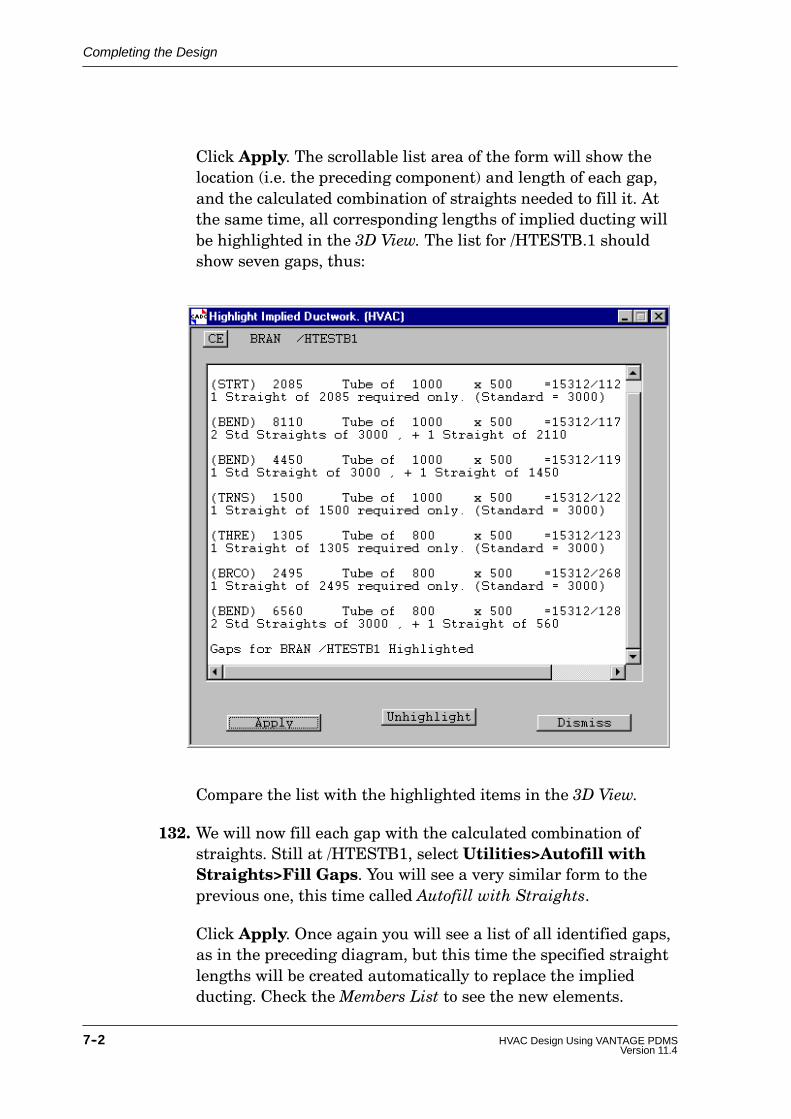
Completing the Design
7--2 HVAC Design Using VANTAGE PDMSVersion 11.4
Click Apply. The scrollable list area of the form will show thelocation (i.e. the preceding component) and length of each gap,and the calculated combination of straights needed to fill it. Atthe same time, all corresponding lengths of implied ducting willbe highlighted in the 3D View. The list for /HTESTB.1 shouldshow seven gaps, thus:
Compare the list with the highlighted items in the 3D View.
132. We will now fill each gap with the calculated combination ofstraights. Still at /HTESTB1, select Utilities>Autofill withStraights>Fill Gaps. You will see a very similar form to theprevious one, this time called Autofill with Straights.
Click Apply. Once again you will see a list of all identified gaps,as in the preceding diagram, but this time the specified straightlengths will be created automatically to replace the impliedducting. Check theMembers List to see the new elements.

Completing the Design
7--3HVAC Design Using VANTAGE PDMSVersion 11.4
133. To check that the autofilling operation was carried out correctly,repeat Step 131. You should now see the message No Gaps ToShow. Do not dismiss the form yet.
Now check that there are no gaps in any of the four sidebranches. To do so, navigate to each in turn, click the CE buttonat the top of the Highlight Implied Ductwork form, then click theApply button. In each case you should see the No Gaps ToShow message. (If not, go back and correct any errors in yourdesign before proceeding.)
13.2 Adding Stiffening Flanges
A utility is provided for calculating the optimum numbers andpositions of stiffening flanges needed to support ductwork items. Theconfiguration of the flanges is tailored to suit the component geometryin each case. You can then create and position such flangesautomatically.
Exercise continues:
134. Navigate to first straight in the main branch (i.e. thesouthernmost straight). To calculate the number of stiffenersneeded for this length of ducting, select the Rectangularcategory on the HVAC form and create Stiffening. You will see aRectangular Stiffening form showing the calculatedrequirements for the current element. Note in particular thenumber of stiffening flanges required (Spec Requirement): inthis case 5.
To create all of the stiffening flanges as specified on the form,click the Apply the Spec Requirement button. The fiveflanges will be created and positioned automatically. Note that,in the branch membership hierarchy, they are treated assubcomponents of the straight (as explained in Section 5.6).
135. Repeat the preceding process to stiffen the next straight which,being shorter, requires only four flanges.
136. Now, proceeding along the branch, add stiffeners to the squarebend, the mitred offset, and the radiused bend. Notice how the

Completing the Design
7--4 HVAC Design Using VANTAGE PDMSVersion 11.4
stiffening flanges are configured to suit the different componentshapes, like this (different shading identifies individualcomponents; heaviest lines show flanges joining componentstogether):
Nfirst straight(5 stiffeners)
second straight (4stiffeners)
square bend (4stiffeners)
fire damper
radiused bend (2stiffeners)
mitred vertical offset(1 stiffener)
13.3 Automatic Item Numbering and Naming
The item numbering facility automatically allocates sequential itemnumbers to all HVAC components and gives each item a name of theformat /PREFIXnumber, where /PREFIX is a user--definable stringand number is the allocated number. Subcomponents (air deflectors,stiffening flanges etc.) are numbered as decimalised subsets of their‘owning’ components.
Inline plant items, which will usually already be named, do not havetheir names changed.
Exercise continues:
137. We will autonumber all HVAC items in our current designmodel, so navigate to the owning HVAC element /HTESTHVACand select Utilities>Automatic Itemising from the mainmenu. You will see an HVAC Itemising form.

Completing the Design
7--5HVAC Design Using VANTAGE PDMSVersion 11.4
Enter the Naming Prefix as /HTEST/ITEM and leave theStart Number set to 1. When you click Apply you will see anHVAC Command Output window listing all HVAC items andtheir allocated numbers.
Compare the entries in this itemising list with those in theMembers List. You will see that each item (except any inlinecomponent) is named in theMembers List using the specifiedprefix /HTEST/ITEM suffixed by the item number. For example,the first two straights in the main branch, and their stiffeningflange subcomponents, appear as follows (the numbers like=15312/112 etc. are internal database reference numbers, whichyou can ignore):

Completing the Design
7--6 HVAC Design Using VANTAGE PDMSVersion 11.4
13.4 Finishing Off Some Design Details
We will now complete some design details which we could not doearlier because they involve the ductwork straights which we haveonly recently created to replace the implied ducting.
First we will modify some joint types to suit the final design, then wewill insert an access panel into the side of a length of ducting.
Exercise continues:
138. When the lengths of implied ducting leading to the two firedampers were replaced with straight components, the connectingjoints will have been assumed to remain as default flangedjoints. In fact, the fire dampers require raw edge joints, suchthat the ducting simply fits over the damper inlet and outlet.
To modify the inlet joint for either damper (i.e. the leave joint forthe straight), navigate to the preceding straight and click theModify CE button on the HVAC form. On the resultingRectangular Straight form (inModify mode), click the LeajointChoose button and, from the Choose Joint form, select RawEdge Joint, slip over 40mm. The leave joint field will now beset to RE40. Apply the change.
Repeat this for the inlet to the other damper.
To modify the outlet joint between the first damper and thesquare bend (i.e. the arrive joint of the bend), navigate to thebend and clickModify CE. On the resulting Rectangular SquareBend form, click the Arrjoint Prev button. The arrive joint fieldwill be set to RE40 by automatic reference to the previouscomponent, namely the fire damper. Apply the change.
139. We will now insert an access panel, whose catalogue definitionincludes a predefined working volume, into the side of the laststraight. (The reason for doing this will become clear when welook at clash checking in the next chapter.)
Navigate to the appropriate straight (the short one, namedHTEST/ITEM21 by the itemising utility, connected to firedamper FD2).
Create a Rectangular Access Panel. From the Select Sizeoptions, which show all panel sizes available in the catalogue,

Completing the Design
7--7HVAC Design Using VANTAGE PDMSVersion 11.4
select 400x350; then click the first Transpose width/depthbutton to give the required configuration (i.e. 350 W x 450 H).When created, the panel appears in the 3D View as a rectangularplate standing slightly proud of the ducting surface. In the nextsection we will look at its ‘hidden’ geometry in more detail.
Run the automatic itemising utility again so that the accesspanel is included in the item list.
13.5 Changing the View Representation
We have already seen how to control which design elements appear inthe 3D View by using the Drawlist to add or remove items asrequired. We have also seen how to control the viewable volume andthe viewing direction by using the Limits and Look options from the3D View’s pop--up menu. We will now see how you can further refinethe view by specifying different levels of detail for the items beingdisplayed.
Exercise continues:
140. The amount of detail shown in the 3D View for different types ofcomponent is controlled by the current representation settings.To see what these settings are, select Settings>Graphics>Representation from the main menu. You will see aRepresentation form. We will look at just two of its options here.
The geometric representation of a catalogue component caninclude, in addition to its normal physical shape, anobstruction volume which represents the space around thecomponent needed for maintenance or operational access. Theaccess panel created in Step 139 is an example of such an item.To see what the obstruction volume looks like, set theObstruction option to Solid on the Representation form and theUpdate all Graphics button to On: click Apply.

Completing the Design
7--8 HVAC Design Using VANTAGE PDMSVersion 11.4
Zoom in close to the access panel and see how its appearance haschanged. The effect, exaggerated here for emphasis, is as follows:
accesspanel
obstructionvolume
To reset the normal view, redisplay the Representation form andset Obstruction to Off, leave Update all Graphics set to On,and click OK.
141. The holes through the walls, where the fire dampers aresituated, may be shown either as boxes (specially shaded to showthat they represent negative boxes, i.e. holes) or as true holes. Sofar we have used the shaded box representation so that we couldpick the holes graphically to identify them. To switch to a morerealistic representation, set the Holes Drawn button to On,leave Update all Graphics set to On, and click Apply.
Look carefully at each hole in turn. You will now be able to seethe ducting and fire dampers where they penetrate the walls.
That completes the introduction to the basic HVAC routingoperations. In the following parts of the exercise we will look at someways of checking the design model and outputting some design dataderived from the database settings.

8--1HVAC Design Using VANTAGE PDMSVersion 11.4
8 Checking and Outputting Design Data
To ensure maximum design integrity, the HVAC application lets youcheck the data in several ways so that any potential mistakes aredrawn to your attention. In this chapter we will look at the methodsof checking for errors and inconsistencies in the HVAC layout, and forclashes (spatial interferences) between design elements.
We will then look at two ways of outputting design data derived fromthe HVAC model: the generation of a tabulated report showing thematerial required to build the design, and the creation of a plotshowing the HVAC layout.
NOTE: Most of the facilities used here are available from all designapplications, so you can readily check and output data fromany combination of design disciplines.
8.1 Querying Some Data Settings
First, we will look at some ways in which you can query specific datasettings as you build up the design model, so that you can checkdetailed design points at any stage.
Exercise continues:
77. Navigate to the square threeway component and then selectQuery> Item Details> Brief Description from the mainmenu. You will see a summary showing the component’s type,key dimensions and joint specifications, like this:

Checking and Outputting Design Data
8--2 HVAC Design Using VANTAGE PDMSVersion 11.4
Repeat this operation for some other components (andsubcomponents).
78. Navigate to the first (i.e. southernmost) straight and selectQuery>Item Details>Item Number. The resulting output,which will say Item Number 1, will be appended to the outputfrom the previous query. Compare the result with the dataillustrated at the end of Section 13.3.
79. At any component, select Query>Item Details>InsulationDepth. The resulting output should always say Insulation 50mm, since we specified this insulation thickness when wecreated each branch.
80. Use the following Query options for several different types ofcomponent:
Query>Position>Origin
Query>Position>Position PA
Query>Position>Position PL
Compare the results with the catalogue definitions for thecorresponding components, as illustrated in Appendix C.
8.2 Checking for Design Data Inconsistencies
The data consistency checking utility reports the following types ofoccurrence (and other similar errors) in the design:
D Branch head or tail reference not set
D Branch head or tail reference type not valid
D Adjoining components have incorrectly ordered PA and PLpoints; for example, one component may have been flipped whileits neighbour was not
D Distance between a component and a connected neighbour, orbetween a component and the branch head or tail, is not valid
D Neighbouring connected components, or a component and thebranch head or tail, have their PA/PL misaligned
D Arrive or leave joint has wrong connection type
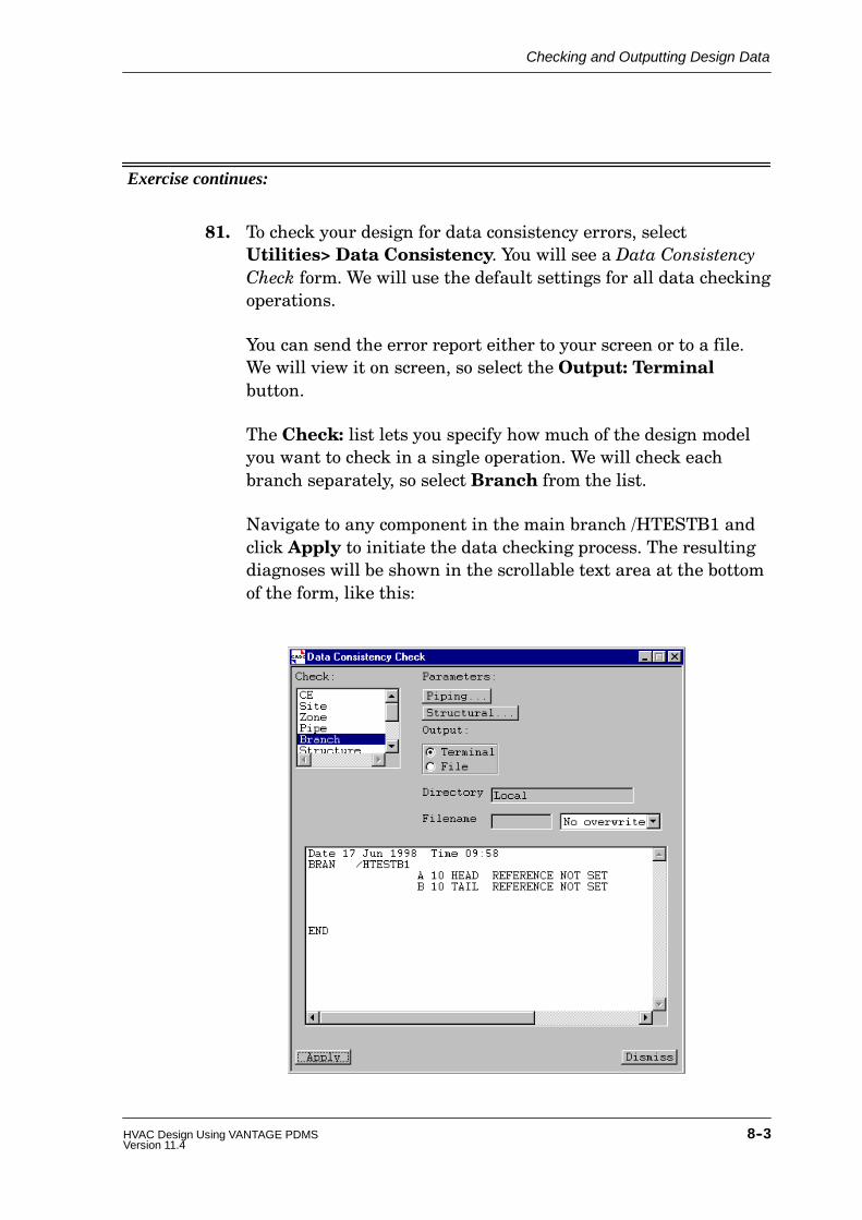
Checking and Outputting Design Data
8--3HVAC Design Using VANTAGE PDMSVersion 11.4
Exercise continues:
81. To check your design for data consistency errors, selectUtilities> Data Consistency. You will see a Data ConsistencyCheck form. We will use the default settings for all data checkingoperations.
You can send the error report either to your screen or to a file.We will view it on screen, so select the Output: Terminalbutton.
The Check: list lets you specify how much of the design modelyou want to check in a single operation. We will check eachbranch separately, so select Branch from the list.
Navigate to any component in the main branch /HTESTB1 andclick Apply to initiate the data checking process. The resultingdiagnoses will be shown in the scrollable text area at the bottomof the form, like this:

Checking and Outputting Design Data
8--4 HVAC Design Using VANTAGE PDMSVersion 11.4
(These two messages remind you that the head and tail of thebranch have not been explicitly terminated and are notconnected to any external items. Each branch end wouldnormally be connected to, say, an air handling unit or to someother ductwork in an adjacent design zone.)
Repeat the check for each of the side branches in turn (for thepurposes of this exercise, ignore any messages which you receiveas a result).
It is good practice to run a data consistency check whenever you havecreated or modified any significant amount of the design, typicallybefore you do a Savework operation.
8.3 Checking for Clashes
The types of clash identified depend on two factors:
D The obstruction levels of the clashing elements
D The current touch and clearance tolerances
Obstruction Levels
All design primitives and all catalogue primitives have an obstructionattribute (OBST) which defines the physical type of obstruction whichthe primitive represents:
D A hard obstruction (OBST=2) represents a rigid andimpenetrable object, such as a steel beam or a plant vessel.
D A soft obstruction (OBST=1) represents a volume which is notsolid but which needs to be kept clear for access.
D Any primitive with OBST=0 represents a freely accessiblevolume and is ignored for clash checking purposes.
Extent Of Clashing
As well as distinguishing between hard and soft clashing items, thechecking utility recognises three categories of clash between them,depending on how far the two primitives intrude on each other’sallocated space. These categories are:

Checking and Outputting Design Data
8--5HVAC Design Using VANTAGE PDMSVersion 11.4
D A physical clash: the primitive volumes overlap by more than aspecified amount. This usually means that a definiteinterference exists.
D A touch: the primitives either overlap by less than the amountneeded to cause a clash or are separated at their closest point byless than a specified distance. This may simply mean that oneitem is resting upon another as intended, or it may indicate aproblem.
D A clearance: the primitives are separated at their closest pointby more than the amount necessary to constitute a touch but lessthan a specified clearance distance. This represents a ‘nearmiss’, which you may want to investigate.
These three classes are illustrated below for the clash specifications:
Touch limits: 5mm overlap to 2mm gap
Clearance limit: 8mm
so that the following criteria apply:
D If the items overlap by more than 5mm, a clash is reported
D If the items overlap by less than 5mm, a touch is reported
D If the items do not overlap but are separated by less than 2mm,a touch is reported
D If the items are separated by more than 2mm but less than 8mm,a clearance is reported
D If the items are separated by more than 8mm, no interference isfound
overlap > 5mm overlap < 5mm 2mm < gap < 8mm
A Physical Clash Touches A Clearance
gap < 2mm
The Clash Detection Process
Each element which is to be checked for clashes has its own geometrychecked against that of all other elements which are specified by a

Checking and Outputting Design Data
8--6 HVAC Design Using VANTAGE PDMSVersion 11.4
current obstruction list. Items which are not in the obstruction listare ignored during the clash checking operations. By default, theobstruction list includes all elements in the database, so that eachelement to be clash checked is tested against every other element. Tocontrol the amount of checking carried out in a large database, youcan restrict the obstruction list to a few specific elements and/or youcan specify a 3D volume (the clash limits) within which the clashchecking is to be confined.
To highlight the locations where clashes are found, the clashing andobstruction items are shown in contrasting colours in the graphicalview (two shades of red, by default).
Exercise continues:
82. We will use the default values for all clash checking settings. Tosee what these are, select Settings>Clasher>Defaults todisplay the Clash Defaults form. Think about the meaning ofeach setting shown (refer to the preceding introduction); thenCancel the form.
83. We will check all of our HVAC components for clashes againstthe building structure. The default obstruction list (all elementsin the current design database) will include both structural andHVAC items. To edit this, selectSettings>Clasher>Obstruction> List. You will see anAdd/Remove Obstruction Items form which is used in a similarway to the Drawlist form (as introduced in Step 8). Remove allcurrent entries and then Add the structural design data only(i.e. /HVACFLOOR, /HVACROOF, /HVACWALLS, /HVACCOLSand /HVACBEAMS).
84. Navigate to the element holding all the HVAC design data whichyou want to check (i.e. /HTESTHVAC) and selectUtilities>Clashes. You will see a Clash Display form. Theleft--hand side of this form controls the clash checking process;the right--hand side consists of a 3D view in which you can lookin detail at any clashes diagnosed. Select Control>Check CEfrom the form’s left--hand menu bar to run the clash checkingprocess and, when completed, study the Clash List which showsany clashes found.
In our case this should show one clash only, with the description

Checking and Outputting Design Data
8--7HVAC Design Using VANTAGE PDMSVersion 11.4
1 SH CLASH /HTEST/ITEM21.1
This identifies a soft--hard (SH) clash between the obstructionvolume associated with the access panel (which we added in Step139 and which is illustrated in Step 140) and the adjacent wall.To see this properly in the form’s 3D view, set the graphicsrepresentation to show obstruction volumes (as explained inStep 140) and zoom in close to the access panel. Notice how theclashing items are highlighted in shades of red (if they are not,repeat the Check CE operation to regenerate the clash data).
85. To see more information about the clash, select Query>Clash>Detail from the Clash Display form’s menu bar. You will see aClash Detail form as follows:
Obstructionvolume foraccess panel
Adjacentwall
Locationof clash
NOTE: If the Auto Clash button is set to On, thus: , each newelement that you create is checked immediately for clashesas the design is built up. This can slow down progress whenyou are adding many new elements, but is very useful whenyou want to add a few new items to an existing design whichhas already been checked for clashes.
8.4 Generating a Data Output Report
The reporting utility lets you read selected information from thedatabase and present the output in a tabulated format. Each reportcan be customised by specifying some or all of the following:

Checking and Outputting Design Data
8--8 HVAC Design Using VANTAGE PDMSVersion 11.4
D Where the output is to appear (on the screen or in a file ready forprinting).
D An introductory header which is to appear at the beginning ofthe report.
D The page length (if the report is to be paginated).
D The page layout, including number and positions of columns,column headings, etc.
D Any headers and footers which are to appear at the top andbottom of each page.
D The selection criteria which define which data settings are to beincluded in the report.
Once such a report has been designed, its specification can be savedfor future use in the form of a report template file. The ways inwhich you define how a given report is to be generated and presentedare beyond the scope of this exercise, but we will look at the results ofthe process by using a pre--prepared template which outputs amaterial take--off list showing the length of tube needed to build ourdesign. (You will probably use your company’s standard templates formost reports anyway, in which case this is the method you wouldnormally use in practice.)
Exercise continues:
86. Select Utilities>Reports>Run to initiate the reporting process.You will see a File Browser listing all files in the currentreporting directory (specified by your System Administrator aspart of the project set--up procedure). Check that you are in the...\REPORTS\TEMPLATES directory. All files with a .tmp suffixare report templates. Select hvac_list.tmp, which has beendesigned to produce a list of the principal components (omittingsubcomponents and branch connectors) in the HVAC design.Click OK on the File Browser.
87. To run the report defined by the chosen template, you mustspecify two things (as determined by the rules within thetemplate): where the report is to appear, and what part of thedatabase hierarchy is to be read when extracting the requiredtypes of data. When you OK the File Browser to specify thetemplate, a Report Details form appears which lets you do this.

Checking and Outputting Design Data
8--9HVAC Design Using VANTAGE PDMSVersion 11.4
Leave the Filename text--box empty (which will send the reportto the screen automatically). In the Hierarchy text--box, enter/HTESTHVAC, since we want to list the components for thewhole of the HVAC network. Click OK to run the report.
88. The tabulated report output will be displayed in a CommandOutput window which is opened automatically, like this:

Checking and Outputting Design Data
8--10 HVAC Design Using VANTAGE PDMSVersion 11.4

Checking and Outputting Design Data
8--11HVAC Design Using VANTAGE PDMSVersion 11.4
This report lists all principal components in the specifiednetwork (in this case the whole of our HVAC design model) inbranch head--to--tail order. The type and key dimensions for eachcomponent are tabulated as predefined by the template; anyother properties could have been added (see list in Section C.10),and the sequence sorted into a different order of priority, ifrequired by the template designer. For example, the inline itemsshown with Item Number 0 could have been identified byanother column showing the component names.
8.5 Plotting the Design Model
PDMS’s drawing module provides very powerful facilities forgenerating annotated and dimensioned plots of all or part of thedesign model. We will use just a small part of this power to producean isometric plot of our HVAC layout using default settings only.
Exercise continues:
In order for the drawing facilities to apply the correct rules forrepresenting HVAC items, we must set a design attribute which willtell the drawing module how to interpret the design data. Theattribute used for this purpose is the Function attribute of theparent Zone.
89. Navigate to the Zone which holds the HVAC design data(/HVACZONE) and selectModify>Attributes. You will see aModify Attributes form listing the current settings for the Zone.The Function attribute will probably say unset; it is thissetting which we need to change.
Select the Function line in the list. You will see a smallFunction form showing the current setting. Edit the text toreplace unset by Heating. OK/Apply the changes.
We must now switch from the DESIGN module, which we have beenusing to create the design model, to the DRAFT drawing module.

Checking and Outputting Design Data
8--12 HVAC Design Using VANTAGE PDMSVersion 11.4
90. Select Design>Modules>Draft>Macro Files.
When the DRAFT applications have been loaded from theirmacro files, you will see the DRAFT General menu bar and anempty 2D view window called Main Display (analogous to the3D View window which we have been using in DESIGN), thus:
Drawing sheet will be displayed here
We must next set up an administrative hierarchy to define how plotsare to be stored (in a real project this would probably have been donefor you already). The parts of the hierarchy with which we areconcerned here are as follows:

Checking and Outputting Design Data
8--13HVAC Design Using VANTAGE PDMSVersion 11.4
DEPARTMENT
REGISTRY(REGI)
(DEPT)
DRAWING(DRWG)
SHEET(SHEE)
LIBRARY(LIBY)
Standard symbols, annotations etc.
VIEW
Design database elements to be drawn
LIBRARY(LIBY)
91. Select Create>Department and name the elementHVACDEPT. Click OK. You will now see a DepartmentInformation form. Attributes set at Department level arecascaded down to all lower levels. To set them, click theAttributes button to display a Department Attributes form. Onthe latter form:
D Select the A4 drawing sheet size (note that this sets theWidth and Height automatically).
D Leave all pen definitions, hatch patterns and terminators attheir default settings.
D From the Ruleset Reference options, select/DRA/PRJ/REPR/GEN/HVAC.
D Set Backing Sheet Reference to Reference and select/DRA/MAS/BACKS/MET/A4_Land. This will applystandard borders and data areas to all drawings created inthis Department.
The settings should now look like this:

Checking and Outputting Design Data
8--14 HVAC Design Using VANTAGE PDMSVersion 11.4
D Click Apply, then Dismiss.
Check that the Create Registry button on the DepartmentInformation form is set to On and OK this form. You will see aCreate REGI form.
92. Name the Registry HVACREGI and click OK. You will see aRegistry Information form. Note that all attribute settings forthe Registry have been copied from its owning Department (anyindividual attribute cascaded in this way can be overwritten at alower level if required).
Set Create Drawing to On and select Explicitly. Click OK.You will see a Create DRWG form.
93. Name the Drawing HVACDRWG and click OK. You will see aDrawing Definition form. Enter the Title as HVAC View. Notethat the Date and Drawn By entries are derived automaticallyfrom your system log--in data. Click Apply, then Dismiss.
Checking and Outputting Design Data
8--15HVAC Design Using VANTAGE PDMSVersion 11.4
That completes the setting up of the drawing administrationhierarchy; we are now in a position to define the content of a drawingsheet ready for viewing and plotting.
94. Select Create>Sheet>Explicitly and OK the Create SHEEform. TheMain Display view will show the backing sheetspecified in Step 91. You will also see a Sheet Definition form.Note that all attribute settings have been cascaded down fromDepartment level. Click Apply, then Dismiss.
The detailed design data, extracted directly from the Design database,is applied to the sheet in the form of individual Views.
95. Select Create>View>User--defined and OK the resulting form.A User-defined View form will be displayed, and a defaultrectangle will be added to theMain Display to show where thedesign data for this view will be plotted.
We will plot a single view on the sheet, so we will first resize thedefault view area to fill the available space. To do so, selectFrame>Size>Cursor from the User-defined View menu. Theresulting Point Construction Option form lets you choose variousways of identifying the extremities of the required area. Usingthe 2D Cursor Hit method, pick points just inside the top--leftand bottom--right corners of the drawing area within the backingsheet layout.
On the User-defined View form, enter the Title as ISO3 View;set the Type to Global Hidden Line; and set the Direction toISO3 (select this using the options available from the middle ofthe three Direction gadgets).
The part(s) of the design model which are to be plotted arespecified by means of a drawlist (similar to the way in which thecontent of a 3D View was specified in DESIGN). SelectGraphics>Drawlist from the User-Defined View menu todisplay the Drawlist Management form. In the Reference ListMembers list, navigate to the HVAC element which holds thecomplete HVAC network (/HTESTHVAC) and click the Addbutton to add it to the drawlist.
We must now set the drawing scale so that the plotted modelrepresentation fits sensibly into the area available on the sheet.First click the Auto Scale button on the User-defined View formand notice how the precisely calculated scale is displayed in the

Checking and Outputting Design Data
8--16 HVAC Design Using VANTAGE PDMSVersion 11.4
adjacent text--box. To modify this to the nearest smaller standardscale, click the Nearest button. The chosen standard scale willnow be displayed (e.g. 1/150). Click Apply to implement the newscale calculation. The final settings will look something like this:
Click the Update Design button to plot the drawlist element(s)in theMain Display at the chosen scale, thus:

Checking and Outputting Design Data
8--17HVAC Design Using VANTAGE PDMSVersion 11.4
This is as far as we will go in this exercise, although the full range of2D drafting facilities available is extensive, allowing you to adddimensioning and labelling data derived directly from the designmodel, and to add any other specific 2D annotation which you require.
8.6 Conclusion
That concludes both the tutorial exercise and this introduction tosome of the ways in which PDMS and the CADCENTRE applicationscan help you in your HVAC design work. We hope that workingthrough this book has given you an insight into the potential power ofPDMS and that you will have gained sufficient confidence to exploresome of the more advanced options on your own.
For further technical details, refer to the sources of information listedin Appendix D.
If you have not already done so, you are strongly advised to attendone or more of the specialised PDMS training courses, which willshow you how to get the maximum benefits from the product in yourown working environment (see Section 1.3).

Index--1Version 11.4HVAC Design Using VANTAGE PDMS
Index
3D view, 3--4
A
Access panel, 7--6
Air turning vanes, 6--10
Application
definition, 1--3loading, 5--3
Attribute, definition, 4--2
B
Branch
definition, 4--1main and side branches, 5--7side, 6--4
Branch head, definition, 4--2
Branch head/tail, connecting, 5--9
Branch tail, definition, 4--2
Button
control, 3--9option, 3--8radio, 3--7toggle, 3--7
C
CE, 4--3
Check box, 3--7
Clash, definition, 8--4
Clash checkingchecking process, 8--5clash limits, 8--6extent of clash, 8--4obstruction levels, 8--4obstruction list, 8--5principles, 8--4
Clash limits, 8--6Clashing extent, 8--4Clearance, definition, 8--5Composite component,representation, 5--11Control button, 3--9Copying existing components, 5--14Current element, definition, 4--3
DData consistency checking, principles,8--2Database hierarchy
Design data, 4--2Draft data, 8--12
Design data, checking, 8--2Design database hierarchy, 4--2Design parameters, 5--1Design session, ending, 4--10Detailing specification, 5--5Display
restoring, 5--2saving, 4--10
Draft applications, loading, 8--11Draft database hierarchy, 8--12

Index
Index--2 HVAC Design Using VANTAGE PDMSVersion 11.4
Draft module, 8--11
Drawlist, 4--5
Ducting, implied, 5--10
EElement, definition, 4--2
Ending design session, 4--10
FForms and display, saving, 4--10
Function attribute, setting forDRAFT, 8--10
GGaps between components
filling automatically, 7--2measuring, 5--15, 7--1
Geometry set, 5--2
Graphical view, 3--4
Grid, for tiling, 6--2
HHard obstruction, 8--4
Head, of branch. See Branch head
Help, on--line, 3--9
Holes, representation, 7--8
HVAC Designer application, loading,5--3
HVAC element, definition, 4--1
HVAC form, 5--3
IImplied ducting, 5--10
Insulation, querying, 8--2
Isometric view, 4--5
Item details, querying, 8--1
Item naming, 7--4Item numbering, 7--4Item numbers, querying, 8--2Itemising, 7--4
JJoints, specifying, 7--6
LLeaving design session, 4--10Limits, setting for view, 4--5List, scrollable, 3--8
MMDB selection, 3--2Member, definition, 4--3
Members list, 3--4Menu, pull--down, 3--5Menu bar, 3--4, 3--5Module, definition, 1--3Module selection, 3--2Mouse buttons, functions, 3--4Multiple database selection, 3--2
NNaming, automatic, 7--4Negative primitive, definition, 4--2Numbering, automatic, 7--4
OObstruction levels, 8--4Obstruction list, 8--5Obstruction volume, representation,7--7On--line help, 3--9Option button, 3--8Owner, definition, 4--3

Index
Index--3Version 11.4HVAC Design Using VANTAGE PDMS
P
P--arrive, 5--1
P--leave, 5--1
P--point
definition, 5--1
p--arrive, 5--1
p--leave, 5--1
point set, 5--2
Panning view, 4--7
Parameters, catalogue components,5--1
Password entry, 3--2
Physical clash, definition, 8--4
Plotting facilities, 8--11
Point set, 5--2
Position, querying, 8--2
Primitive
definition, 4--2
geometry set, 5--2
Project selection, 3--2
Prompts, 3--6
Pull--down menu, 3--5
R
Radio button, 3--7
Reports
generating, 8--7
principles, 8--7
templates, 8--8
Representation
holes, 7--8
obstruction volumes, 7--7
Rotating view, 4--7
SSave work facility, 4--9Saving design changes, 4--9Screen layout
restoring, 5--2saving, 4--10
Scrollable list, 3--8Setting out point (SOP), 6--2Side branch, 6--4Site, definition, 4--1Soft obstruction, 8--4Specification, detailing, 5--5Status bar, 3--4, 3--6Status form, 3--6Stiffeners, adding, 7--3Structure, definition, 4--2Subcomponent, 5--11Submenu, 3--5
TTail, of branch. See Branch tailText box, 3--7Tile, positioning, 6--3Toggle button, 3--7Tool bar, 3--4Touch, definition, 8--4Training courses, 1--2
UUser name entry, 3--2
VView
3D/graphical, 3--4, 4--4centre of interest, 4--9panning, 4--7rotating, 4--7zooming, 4--7
View direction, 4--5

Index
Index--4 HVAC Design Using VANTAGE PDMSVersion 11.4
WWorld, definition, 4--1
ZZone, definition, 4--1Zooming view, 4--7