hvac using pdms vol1
TRANSCRIPT

8/8/2019 Hvac Using Pdms Vol1
http://slidepdf.com/reader/full/hvac-using-pdms-vol1 1/99
HVAC Design Using VANTAGE PDMSVolume 1
PDMS Version 11.6
pdms1160/HVAC Using PDMS Vol1
issue 230804
8/8/2019 Hvac Using Pdms Vol1
http://slidepdf.com/reader/full/hvac-using-pdms-vol1 2/99
PLEASE NOTE:
AVEVA Solutions has a policy of continuing product development: therefore, the information
contained in this document may be subject to change without notice.
AVEVA SOLUTIONS MAKES NO WARRANTY OF ANY KIND WITH REGARD TO THIS
DOCUMENT, INCLUDING BUT NOT LIMITED TO, THE IMPLIED WARRANTIES OF
MERCHANTABILITY AND FITNESS FOR A PARTICULAR PURPOSE.
While every effort has been made to verify the accuracy of this document, AVEVA Solutions shall
not be liable for errors contained herein or direct, indirect, special, incidental or consequential
damages in connection with the furnishing, performance or use of this material.
This manual provides documentation relating to products to which you may not have access or which
may not be licensed to you. For further information on which Products are licensed to you please refer
to your licence conditions.
© Copyright 1991 through 2004 AVEVA Solutions Limited
All rights reserved. No part of this document may be reproduced, stored in a retrieval system or
transmitted, in any form or by any means, electronic, mechanical, photocopying, recording or
otherwise, without prior written permission of AVEVA Solutions.
The software programs described in this document are confidential information and proprietary
products of AVEVA Solutions or its licensors.
For details of AVEVA's worldwide sales and support offices, see our website at
http://www.aveva.com
AVEVA Solutions Ltd, High Cross, Madingley Road, Cambridge CB3 0HB, UK
8/8/2019 Hvac Using Pdms Vol1
http://slidepdf.com/reader/full/hvac-using-pdms-vol1 3/99
Revision History
Date Version NotesSeptember 2003 11.5 Updated to incorporate the Design Explorer and the new view
manipulation facilities introduced at this version of PDMS.
August 2004 11.6 Changed to add new Design Explorer and Reference List.
HVAC Design Using VANTAGE PDMS Revision History-i Version 11.6

8/8/2019 Hvac Using Pdms Vol1
http://slidepdf.com/reader/full/hvac-using-pdms-vol1 4/99
Revision History
Revision History-ii HVAC Design Using VANTAGE PDMSVersion 11.6
8/8/2019 Hvac Using Pdms Vol1
http://slidepdf.com/reader/full/hvac-using-pdms-vol1 5/99
Contents
1 Read This First 1-1
1.1 The scope of this guide ...................................................................................................1-1 1.1.1 Intended audience............................................................................................1-1 1.1.2 Assumptions ....................................................................................................1-1 1.1.3 About the tutorial exercise...............................................................................1-1 1.1.4 Further reading ................................................................................................1-2
1.2 Text conventions.............................................................................................................1-2 1.3 Terminology....................................................................................................................1-2 1.4 How the guide is organised.............................................................................................1-3 1.5 Further training in the use of PDMS...............................................................................1-4
2 Introducing VANTAGE PDMS 2-1 2.1 Introducing the structure of PDMS.................................................................................2-1 2.2 The strengths of PDMS...................................................................................................2-1 2.3 PDMS HVAC design features ........................................................................................2-2
3 Getting Started 3-1 3.1 Logging in.......................................................................................................................3-1 3.2 Using the mouse..............................................................................................................3-2 3.3 Using forms.....................................................................................................................3-2
3.3.1 Using text boxes..............................................................................................3-2 3.3.2 Using drop-down lists .....................................................................................3-3
3.4 The PDMS startup display ..............................................................................................3-4 3.5 Using menus....................................................................................................................3-5 3.6 Using the tool bar............................................................................................................3-6 3.7 Using the Design Explorer..............................................................................................3-7 3.8 Using the status bar.........................................................................................................3-8 3.9 More on using forms.......................................................................................................3-8
3.9.1 Using option buttons .......................................................................................3-9 3.9.2 Using check boxes...........................................................................................3-9 3.9.3 Using scrollable lists .......................................................................................3-9 3.9.4 Using action buttons......................................................................................3-10
3.10 Responding to alert forms.............................................................................................3-10 3.11 Using on-line Help........................................................................................................3-10
4 Learning about the PDMS Database Hierarchy 4-1 4.1 How PDMS stores design data........................................................................................4-1
4.1.1 PDMS design data definitions.........................................................................4-2
4.2 Viewing the design..........................................................................................................4-3 4.2.1 Exploring the HVAC database hierarchy........................................................4-4
4.3 Viewing the design..........................................................................................................4-4 4.3.1 Setting the scale and direction of the view......................................................4-4 4.3.2 Using the draw list ...........................................................................................4-5 4.3.3 Manipulating the displayed view.....................................................................4-7
4.4 Saving the current design and leaving your design session ............................................4-9
5 Routing a Sequence of HVAC Components 5-1 5.1 HVAC component representation in the catalogue.........................................................5-1
5.1.1 HVAC physical shape .....................................................................................5-1 5.1.2 HVAC variables ..............................................................................................5-1
5.2 Restoring your PDMS session and starting the HVAC application................................5-2 5.3 Setting HVAC defaults ...................................................................................................5-3
HVAC Design Using VANTAGE PDMS Contents-i Version 11.6

8/8/2019 Hvac Using Pdms Vol1
http://slidepdf.com/reader/full/hvac-using-pdms-vol1 6/99
Contents
5.3.1 Setting a default detailing specification ..........................................................5-3 5.3.2 Choosing the HVAC form format ...................................................................5-3 5.3.3 Customising HVAC forms ..............................................................................5-5
5.4 Creating HVAC administrative elements........................................................................5-6
5.4.1 Creating an HVAC system element ................................................................5-6 5.4.2 Creating an HVAC branch element.................................................................5-6
5.5 Creating HVAC components ..........................................................................................5-8 5.5.1 Creating a fire damper...................................................................................5-10 5.5.2 Moving the fire damper.................................................................................5-10 5.5.3 Creating a composite component ..................................................................5-11
5.6 Adding more HVAC components to your ductwork ....................................................5-13 5.6.1 Creating a rectangular radiused bend ............................................................5-13 5.6.2 Repositioning the rectangular radiused bend.................................................5-13 5.6.3 Creating a rectangular mitred offset..............................................................5-14 5.6.4 Creating a second rectangular radiused bend................................................5-14 5.6.5 Adding a circular section silencer .................................................................5-15 5.6.6 Adding a three-way component and terminating the branch.........................5-16 5.6.7 Defining the branch tail.................................................................................5-17
6 Adding to the HVAC Model 6-1 6.1 The grid/tiling utility.......................................................................................................6-1 6.2 Creating side branches ....................................................................................................6-3
7 Completing the Design 7-1 7.1 Filling ductwork gaps automatically...............................................................................7-1 7.2 Adding stiffening flanges................................................................................................7-4 7.3 Automatic item numbering and naming..........................................................................7-5 7.4 Finishing off design details.............................................................................................7-6
7.4.1 Modifying joint types ......................................................................................7-7 7.4.2 Inserting an access panel .................................................................................7-7
7.5 Changing the view representation...................................................................................7-8
8 Checking and Outputting Design Data 8-1 8.1 Querying data settings.....................................................................................................8-1 8.2 Checking for design data inconsistencies .......................................................................8-2 8.3 Data check functions.......................................................................................................8-4 8.4 Checking for clashes .......................................................................................................8-4
8.4.1 Obstruction levels............................................................................................8-4 8.4.2 Extent of clashing............................................................................................8-5 8.4.3 The clash detection process.............................................................................8-6
8.5 Generating a data output report.......................................................................................8-8 8.5.1 Generating a tabulated data report...................................................................8-8 8.5.2 Plotting the design model ..............................................................................8-10 8.5.3 Setting up a drawing administration hierarchy..............................................8-11 8.5.4 Defining the content of a drawing sheet........................................................8-14
8.6 Conclusion ....................................................................................................................8-17
Contents-ii HVAC Design Using VANTAGE PDMSVersion 11.6

8/8/2019 Hvac Using Pdms Vol1
http://slidepdf.com/reader/full/hvac-using-pdms-vol1 7/99
1 Read This First
1.1 The scope of this guide
This guide introduces some of the facilities provided by VANTAGE PDMS for the
design and documentation of interconnected Heating, Ventilation and Air
Conditioning (HVAC) ducting networks. It explains the main concepts underlying
PDMS and its supporting applications, and shows how you can apply these to your
own design projects.The chapters of this guide take the form of a hands-on tutorial exercise combined
with frequent explanation of the underlying concepts. As you work progressively
through the exercise, you will gain practical experience of the ways in which you
can use PDMS while learning about the powerful facilities it provides.
1.1.1 Intended audience
This guide has been written for engineers familiar with HVAC design practices, who
may or may not have prior knowledge of PDMS.
1.1.2 Assumptions
For you to use this guide, the sample PDMS project, Project SAM, must be correctly
installed on your system, and you must have read/write access to the project
databases.
It is assumed that you know:
• where to find PDMS on your computer system
•
you know how to use the Windows operating system installed on your site.Contact your systems administrator if you need help in either of these areas.
1.1.3 About the tutorial exercise
All the steps of the exercise are numbered sequentially throughout the guide. The
start and end of each part of the exercise is marked by lines across the page to
separate them from the general information sections, like this:
HVAC Design Using VANTAGE PDMS 1-1Version 11.6
8/8/2019 Hvac Using Pdms Vol1
http://slidepdf.com/reader/full/hvac-using-pdms-vol1 8/99
Read This First
1.1.4 Further reading
You can find a list of relevant AVEVA documentation in the appendices of this
guide.
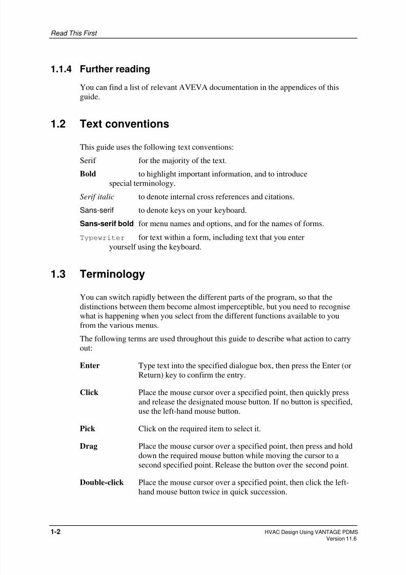
1.2 Text conventions
This guide uses the following text conventions:
Serif for the majority of the text.
Bold to highlight important information, and to introduce
special terminology.
Serif italic to denote internal cross references and citations.
Sans-serif to denote keys on your keyboard.
Sans-serif bold for menu names and options, and for the names of forms.
Typewriter for text within a form, including text that you enter
yourself using the keyboard.
1.3 Terminology
You can switch rapidly between the different parts of the program, so that the
distinctions between them become almost imperceptible, but you need to recognise
what is happening when you select from the different functions available to you
from the various menus.
The following terms are used throughout this guide to describe what action to carry
out:
Enter Type text into the specified dialogue box, then press the Enter (or
Return) key to confirm the entry.
Click Place the mouse cursor over a specified point, then quickly press
and release the designated mouse button. If no button is specified,use the left-hand mouse button.
Pick Click on the required item to select it.
Drag Place the mouse cursor over a specified point, then press and hold
down the required mouse button while moving the cursor to a
second specified point. Release the button over the second point.
Double-click Place the mouse cursor over a specified point, then click the left-
hand mouse button twice in quick succession.
1-2 HVAC Design Using VANTAGE PDMSVersion 11.6

8/8/2019 Hvac Using Pdms Vol1
http://slidepdf.com/reader/full/hvac-using-pdms-vol1 9/99
Read This First
1.4 How the guide is organised
This guide comprises two volumes divided into chapters and appendices, as follows:
Volume 1 (this volume):
Chapter 1 introduces this guide and summarises its scope.
Chapter 2 gives a general overview of the main design facilities provided
within the HVAC application.
Chapter 3 gives you a general guide to using the PDMS graphical user
interface, including an explanation of how to access detailed on-
line help. A running example is used from this chapter on, to
illustrate essential concepts.
Chapter 4 explains how PDMS stores its design data and shows you how to
organise your data.
Chapter 5 demonstrates the key features of HVAC design using PDMS and
shows you how to build up a ductwork sequence component by
component.
Chapter 6 shows you how to extend the basic ductwork sequence by adding
side branches to form a more complex network. In doing so, it
introduces a useful facility for creating a reference grid which can
be used to position ceiling tiles for locating HVAC grilles etc.
Chapter 7 explains some ways of finishing off the design details by using
some automated facilities provided by the application.
Chapter 8 shows how to check your design for clashes, and how to generate
reports and plots directly from the design data. It concludes the
worked example.
Volume 2:
Appendix A shows the complete hierarchy of all options available from theapplication bar menus, pull-down menus and submenus in a
convenient quick-reference format.
Appendix B summarises the database hierarchy which PDMS uses to store
your HVAC design data.
Appendix C contains annotated illustrations of all of the HVAC components
which are provided in the catalogue database which forms an
integral part of the product.
Appendix D contains some examples of the types of HVAC layout plots which
can be produced easily by using PDMS
HVAC Design Using VANTAGE PDMS 1-3 Version 11.6

8/8/2019 Hvac Using Pdms Vol1
http://slidepdf.com/reader/full/hvac-using-pdms-vol1 10/99
Read This First
Appendix E identifies other sources of information which supplement, and
expand upon, the brief details given in this guide.
The guide concludes with an index, allowing you to refer back to any specific topics
about whose details you need to be reminded.
1.5 Further training in the use of PDMS
This guide teaches you about the key features of using PDMS for HVAC designs
only.
If you wish to learn more about the wide-ranging facilities of PDMS, AVEVA
provides a wide range of training courses, covering all levels of expertise and all
design disciplines. For details of courses, and to arrange course attendance, contact
your nearest AVEVA support office (see the copyright page at the front of this guidefor our web address).
1-4 HVAC Design Using VANTAGE PDMSVersion 11.6

8/8/2019 Hvac Using Pdms Vol1
http://slidepdf.com/reader/full/hvac-using-pdms-vol1 11/99
2 Introducing VANTAGE PDMS
This chapter introduces:
• the structure of PDMS
• the strengths of PDMS
• HVAC design features.
2.1 Introducing the structure of PDMS
PDMS comprises the following functional parts:
• modules
• applications.
A module is a subdivision of PDMS that you use to carry out specific types of
operation. This guide covers the following modules:
• Design, which you use for creating the 3D design model
• Draft, which you use for generating annotated and dimensioned drawings of
your design.
• An application is a supplementary program that has been tailored to provide
easy control of operations that are specific to a particular discipline. The
application you will use for HVAC design work in this guide the HVAC
Designer.
You can switch quickly and easily between different parts of PDMS.
2.2 The strengths of PDMS
In VANTAGE PDMS, you have a powerful suite of facilities for the creation,
analysis and documentation of interconnected HVAC ducting networks.
The emphasis is on maximising both design consistency and design productivity:
• The design modelling functions incorporate a degree of apparent intelligence
that enables them to make sensible decisions about the consequential effects of
many of your design choices. This allows you to implement a sequence of
related decisions with a minimum of effort.
• You can incorporate modifications into your design at any stage without fear of
invalidating any of your prior work, because data consistency-checking is an
integral part of the product. PDMS automatically manages drawing production,
HVAC Design Using VANTAGE PDMS 2-1Version 11.6

8/8/2019 Hvac Using Pdms Vol1
http://slidepdf.com/reader/full/hvac-using-pdms-vol1 12/99
Introducing VANTAGE PDMS
material take-off reports, and so on, by reading all design data directly from a
common set of databases, to prevent errors from being introduced by
transcribing information between different disciplines.
• The applications let you check all aspects of your design as work progresses.This includes on-line interdisciplinary clash detection, so the chances of errors
and inconsistencies reaching the final documented design are reduced to an
exceptionally low level.
• The applications are controlled from a graphical user interface. This means that
all design, drawing and reporting operations are initiated by selecting choices
from menus, and by entering data into on-screen forms. For ease of use, you can
select most of the components you require by picking them from a set of
diagrammatic representations, and many common actions are represented by
pictorial icons.
• On-screen help is available to assist you whenever you need help.
2.3 PDMS HVAC design features
VANTAGE PDMS has been designed by HVAC engineers for HVAC engineers.
The HVAC application offers the following key benefits:
• The HVAC Designer application lets you build up and detail complex ducting
networks simply by selecting components from standard catalogues. By using
standard default settings, a conceptual layout can be created and analysed
rapidly, leaving the design details to a later post-approval stage.
• The application provides facilities for creating rectangular, circular and oval
cross-sectional items. Individual design components can be selected from over
100 parametric catalogue items covering all likely requirements, including a
range of auxiliary items such as stiffening frames, access panels, splitter plates
etc., all of which will be accurately detailed in the design model. The catalogue
also includes a range of inline plant items such as centrifugal and axial fans, air
handling units, silencers, dampers etc., each ready for insertion into the design
model in a single operation.
•
User-definable detailing specifications, such as those for construction materials,ductwork gauge, flange dimensions etc., define precise manufacturing
requirements. User-definable default settings ensure compliance with company
standards and a high level of design consistency throughout the project.
• Accurate geometric representation of all design items ensures reliable clash
checking during the design process, leading to good space management and the
early elimination of positional errors.
• Explicitly positioned design components are interconnected automatically with
implied ductwork as the design of the ductwork sequence is built up. An
autofilling facility is provided which can then calculate the optimum use of
standard ducting straights to complete the material take-off list for the entirenetwork.
2-2 HVAC Design Using VANTAGE PDMSVersion 11.6

8/8/2019 Hvac Using Pdms Vol1
http://slidepdf.com/reader/full/hvac-using-pdms-vol1 13/99
Introducing VANTAGE PDMS
• Several design aids are incorporated, including a facility for creating horizontal
grids which can be used to position ceiling tiles. This can greatly aid the layout
of building services in an architectural environment.
• HVAC elements may be named in accordance with a predefined set of rules, sothat their positions in the database hierarchy are always obvious without you
having to enter specific texts during the design process.
• The application’s user interface can be tailored readily to suit the level of
experience of any individual user. In particular, graphical illustrations of all
catalogue items can be displayed if required to simplify component selection
and dimensioning.
• You can carry out multi-disciplinary clash checks at any stage of the design,
thus avoiding spatial conflicts within the overall model which could be
expensive to rectify at the construction stage. This is particularly important
where different features of the design model are under the control of different
designers.
• At any stage of your work, you can create reports listing specified data from the
current database. You can specify a standard report template, so you can derive
lists of commonly-required information very quickly, or you can design a one-
off report format to suit special needs. The resultant output, which can include
data from any design discipline, sorted in any way you require, can be either
displayed on your screen or sent to a file (for storage and/or for printing).
HVAC Design Using VANTAGE PDMS 2-3 Version 11.6

8/8/2019 Hvac Using Pdms Vol1
http://slidepdf.com/reader/full/hvac-using-pdms-vol1 14/99
Introducing VANTAGE PDMS
2-4 HVAC Design Using VANTAGE PDMSVersion 11.6
8/8/2019 Hvac Using Pdms Vol1
http://slidepdf.com/reader/full/hvac-using-pdms-vol1 15/99
3 Getting Started
This chapter explains:
• how to log in to PDMS
• how to use the windows, menus and forms that comprise the PDMS graphical
user interface
• on-line help.
3.1 Logging in
This is the first step of the tutorial exercise. If you do not know where the PDMS
program is stored on your system, you will have to contact your system
administrator at this point.
Exercise begins:
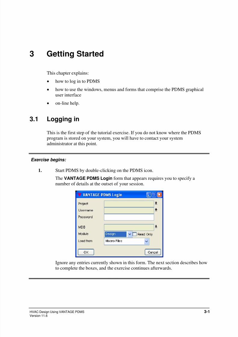
1. Start PDMS by double-clicking on the PDMS icon.
The VANTAGE PDMS Login form that appears requires you to specify anumber of details at the outset of your session.
Ignore any entries currently shown in this form. The next section describes how
to complete the boxes, and the exercise continues afterwards.
HVAC Design Using VANTAGE PDMS 3-1Version 11.6
8/8/2019 Hvac Using Pdms Vol1
http://slidepdf.com/reader/full/hvac-using-pdms-vol1 16/99
Getting Started
3.2 Using the mouse
You use the mouse to steer the graphics cursor around the screen and to select or
pick items by using the mouse buttons. The buttons perform different tasksdepending on the type of window, and the position within the window, where the
cursor is positioned. The appearance of the cursor changes according to the type of
display item that is underneath it.
The left-hand mouse button has three functions:
• On a graphical view, clicking the left-hand button with the cursor over a design
element results in that element becoming the current element (that is, the design
item on which you want to carry out the next operation).
• In a sequence of menus, dragging with the left-hand button activates the
command represented by the highlighted menu option when the button isreleased.
• On a form, the effect varies according to what you select.
The middle mouse button is used primarily to manipulate a graphical view; the right-
hand button (which gives a shortcut menu) is used to access the menu options
specific to the graphical view window.
3.3 Using forms
Forms can include any of the following:
• text boxes
• drop-down lists
• option buttons
• check boxes
• scrollable lists
• action buttons.
Text boxes and drop-down lists are explained below; the remainder are explainedlater in this chapter.
3.3.1 Using text boxes
Text boxes are the areas where you type in alphanumeric data such as names or
dimensions. A text box will usually have a label to tell you what to enter.
When you first open a form which contains text boxes, the first text-box on the form
is current and a text editing cursor (a vertical bar) is displayed in the box. A text-box
often contains a default entry (such as unset) when first displayed. Some text boxes
3-2 HVAC Design Using VANTAGE PDMSVersion 11.6
8/8/2019 Hvac Using Pdms Vol1
http://slidepdf.com/reader/full/hvac-using-pdms-vol1 17/99
Getting Started
accept only text or only numeric data, and entries with the wrong type of data are not
accepted.
To enter data into a text box:
• Click in the box to insert the text editing cursor.
• Type in the required data, editing any existing entry as necessary. (You may
need to delete the existing entry first.)
• When you have finished, confirm the entry by pressing the Enter (or Return)
key. Any text box with an unconfirmed setting is highlighted by a yellow
background.
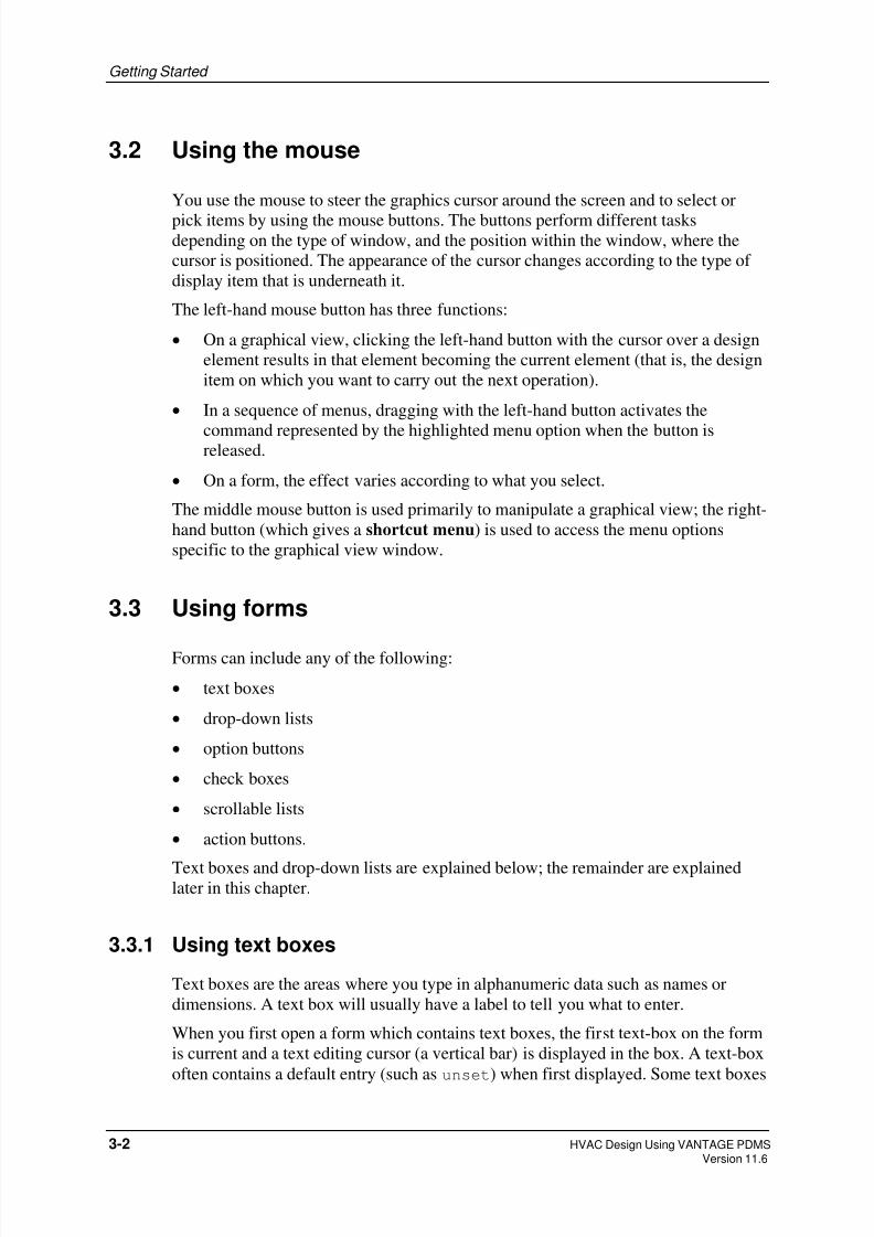
3.3.2 Using drop-down lists
Drop-down lists let you choose one option from a multiple selection. The list will
usually have a label to tell you what you are setting and will show the current
selection.
They typically have the following appearance:
To change the setting, click on the down arrow or button face to reveal the full list of
available options, then pick the required option.
Exercise continues:
2. Click on the VANTAGE PDMS Login form to make it active.
3. Give the name of the Project in which you want to work: enter SAM.
4. Give your allocated Username: enter HVAC.
5. Give your allocated Password: enter HVAC.
6. Give the part of the project Multiple Database (MDB) you want to work in:
enter HVAC.
7. Give the name of the module you wish to use: select Design.
Make sure that you leave the Read Only box unchecked, so that you can
modify the database as you work.
8. You must specify which files to load at startup. You can choose either the
application default settings (Load from Macro Files) or a customised
setup saved during an earlier session (Load from Binary Files). Select
Macro Files.
When you have entered all the necessary details, the form looks like this:
HVAC Design Using VANTAGE PDMS 3-3 Version 11.6

8/8/2019 Hvac Using Pdms Vol1
http://slidepdf.com/reader/full/hvac-using-pdms-vol1 18/99
Getting Started
Click .
3.4 The PDMS startup display
When PDMS has loaded, your screen looks like this:
Title Bar
Main Menu Bar
Main Toolbar
3D View Toolbar
3D Gra hical View
As labelled above, the display comprises the following:
Status Bar
Title Bar
This shows the current PDMS module, and its sub-application if applicable.
3-4 HVAC Design Using VANTAGE PDMSVersion 11.6

8/8/2019 Hvac Using Pdms Vol1
http://slidepdf.com/reader/full/hvac-using-pdms-vol1 19/99
Getting Started
Main Menu Bar
This is the area you use to make menu selections.
Main Tool Bar This has a number of icon buttons and drop-down lists that offer shortcuts
to a selection common PDMS operations and standard settings.
Design Explorer
This shows your current position in the PDMS database hierarchy. To
move to a different point in the database, you click on the appropriate item
in the list. Section 3.7 below explains more about how to use the Design
Explorer.
3D Graphical View
This is the window in which you display the design model graphically as
you build it. A pop-up menu (which you access with the right-hand mouse
button) enables you to control how the model is represented. This window
also has its own tool bar.
Status Bar
This displays information about the current status of your operations.
You can reposition or minimise these windows at any time using standard window
management facilities.
3.5 Using menus
Menu options in pull-down or pop-up menus can be in any of three formats:
Standalone options initiate an action immediately.
Options followed by three dots display a form.
Options followed by a pointer, display a subsidiary menu that
offers a further range of options.
Throughout this guide, related selections from menus are abbreviated form using the
> symbol as a separator. For example:
Select Position>Move>Distance means:
a) Select Position from the bar men.
b) Select Move from the resulting pull-down menu
c) Move the cursor to the right and select Distance from the resultant
submenu.
HVAC Design Using VANTAGE PDMS 3-5 Version 11.6

8/8/2019 Hvac Using Pdms Vol1
http://slidepdf.com/reader/full/hvac-using-pdms-vol1 20/99
Getting Started
3.6 Using the tool bar
The tool bar is displayed immediately below the main menu bar in the application
window. It contains a number of icon buttons which let you carry out common taskswithout searching for the options in the menus.
The actions of the buttons are explained in the on-line help. If you pause the cursor
over a button, a tool-tip pop-up box will remind you of the function of the button. To
activate a button, you click on it.
Note: The tool bar can be switched off, or displayed with larger icons. To do so,
select Settings>System from the main menu bar and then set the required
options on the resulting System Settings form.
3-6 HVAC Design Using VANTAGE PDMSVersion 11.6

8/8/2019 Hvac Using Pdms Vol1
http://slidepdf.com/reader/full/hvac-using-pdms-vol1 21/99
Getting Started
3.7 Using the Design Explorer
The Design Explorer presents a hierarchical view of the PDMS databases and makes
navigating around the Design Database quick and easy.
The figure below shows a typical example of the information the Design Explorer
displays:
To expand or collapse any branch of the tree, click on the or icon.
You can reduce the amount of information the tree displays by ticking the filtercheckbox and selecting one of the predefined core filters from the drop-down
combo-box list. If you want to narrow the view down even more, you can change the
settings in the Explorer Settings, which you can access by selecting
Settings>Explorer from the main menu.
If you place the mouse-pointer over an element, you will get a ToolTip that gives the
element’s name, type, and description; clicking-the right mouse-button while the
cursor is over an element will bring up a context menu from which you can choose
to perform various actions. What actions are available depend on which DB and
module you are using.
HVAC Design Using VANTAGE PDMS 3-7 Version 11.6

8/8/2019 Hvac Using Pdms Vol1
http://slidepdf.com/reader/full/hvac-using-pdms-vol1 22/99
Getting Started
You can drag-and-drop elements within the Design Explorer to copy them, or you
can drag-and-drop from the Explorer to add elements to the 3D view and My Data.
The Current Element is highlighted in the tree view and the Current Element will
change to follow selections made elsewhere, even if the Explorer is not the activewindow. If you set the Expand to CE check box in the Explorer Settings, the tree will
automatically expand to show the Current Element if it is not currently in view.
The Current Element is also the displayed in the History List, which you will find by
default on the main menu bar. The figure below shows the History List.
You can make another element the Current Element using the History List by:
• typing the element’s name into the combo box;
• selecting a previously typed in element from the combo-box’s pull-down list.
Note that if you dock the window vertically, it will not display the combo-
box.;
• navigating through the history one element at a time using the backwards and
forwards buttons;
• selecting elements from anywhere in the History List using the drop down
lists on the backwards and forwards buttons.
3.8 Using the status bar
The status bar displays messages telling you what actions the application is carrying
out. You should look at it frequently, especially if the system appears to be waiting
for you to do something, since it will always prompt you for any input or action
which is required to carry out the next step of your current activity.
If the prompt lets you repeat a task an unspecified number of times, such as picking
a selection of items using the cursor, you must press the Escape key when you have
finished to indicate that you are ready to move to the next operation.
3.9 More on using forms
Forms are used both to display information and to let you enter new data. Forms
typically comprise an arrangement of buttons of various types, text-boxes, and
scrollable lists. Input to a form is usually via a combination of mouse and keyboard.
While you have access to a form, you can change a setting, return to the initial
values, accept and act on the current data, or cancel the form without applying any
changes, according to the nature of the form.
3-8 HVAC Design Using VANTAGE PDMSVersion 11.6

8/8/2019 Hvac Using Pdms Vol1
http://slidepdf.com/reader/full/hvac-using-pdms-vol1 23/99
Getting Started
You were introduced to text boxes and drop-down lists in Section 3.3; this section
describes the remaining boxes, buttons and lists:
• option buttons
• check boxes
• scrollable lists
• action buttons.
3.9.1 Using option buttons
Option buttons are used to select one, and only one, from a group of options. The
selection is mutually exclusive, so that selecting one option deselects others in that
group automatically.
They typically have the following appearance:
Option selected
Option not selected
To change the selected option button in a group, click the required button.
3.9.2 Using check boxes
Check boxes are used to switch an option between two states, typically set andunset. Unlike option buttons, they do not interact, so that you can set any
combination of check boxes at the same time.
They typically have the following appearance:
Set
Unset
3.9.3 Using scrollable lists
A scrollable list is displayed as a vertical list of options within the form, with
vertical and horizontal scroll bars along its sides. To select an option, click on the
line you want. The selected line is highlighted.
Some scrollable lists let you make only a single selection, so that selecting any
option deselects all others automatically. Other lists let you make multiple
selections, with all selected options highlighted simultaneously. You can deselect a
highlighted option in a multiple-choice list, by clicking on it again (repeated clicks
toggle a selection).
HVAC Design Using VANTAGE PDMS 3-9 Version 11.6
8/8/2019 Hvac Using Pdms Vol1
http://slidepdf.com/reader/full/hvac-using-pdms-vol1 24/99
Getting Started
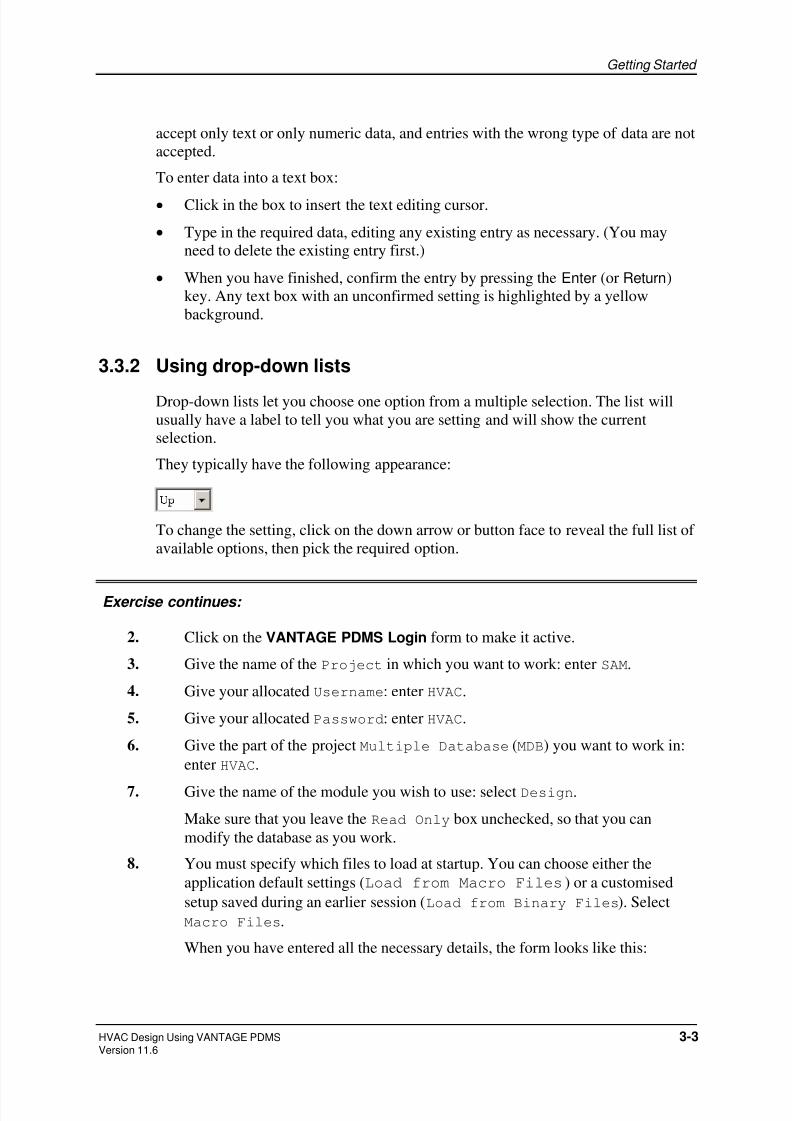
3.9.4 Using action buttons
Most forms include one or more action buttons. You use these to tell PDMS what to
do with the details you have entered in the form.The common action buttons are:
Tells PDMS to accept the current form settings, and closes the form.
Cancels any changes you have made to the form, and closes the form.
Tells PDMS to accept the current form settings, and leaves the form
displayed for further use.
Cancels any changes you have made to the form, and leaves the form
displayed for further use.
Closes the form, keeping the current settings.
Some forms contain more specific types of action button which carry out particular
instructions. The action is indicated by the name of the button (such Add or
Remove).
3.10 Responding to alert forms
Alert forms are used to display information such as error messages, prompts and
requests for confirmation of changes. You respond to these by carrying out the task
prompted for, or by clicking on one of the action buttons on the form (usually an OK
or Cancel button).
3.11 Using on-line Help
Most bar menus end with a Help option. Where available, on-line help gives detailed
instructions on how to use the forms and menus from which you control each
application.
Choosing one of the Help options will bring up the Help window. The picture below
shows a typical example of what you will see:
3-10 HVAC Design Using VANTAGE PDMSVersion 11.6

8/8/2019 Hvac Using Pdms Vol1
http://slidepdf.com/reader/full/hvac-using-pdms-vol1 25/99
Getting Started
The pane on the right shows by default a clickable image of the main PDMS Design
window. If you click on an area of the image, the image will be replaced by text that
describes the part of the image you clicked on.
The left pane contains a set of tabs that allow you to use Help in different ways.
Choosing one of the options described below activates the relevant tab for you so itis at the front when the Help window comes up.
The Help option gives you the following choices from its submenu:
Help>Contents
This displays the Help window so that you can find the required topic from the
hierarchical contents list.
Help>Index
This displays the Help window with the Index tab selected, so that you can browse
for the topic you want to read about from the alphabetically-arranged list. You can
locate topics quickly by typing in the first few letters of their title.
Help>Search
This displays the Help window with the Search tab at the front so that you can find
all topics containing the keywords you specify.
Help>About
This displays information about the current operating system on your computer and
about the versions of PDMS and its applications to which you have access.
HVAC Design Using VANTAGE PDMS 3-11 Version 11.6

8/8/2019 Hvac Using Pdms Vol1
http://slidepdf.com/reader/full/hvac-using-pdms-vol1 26/99
Getting Started
Pressing the F1 key at any time will display the help topic for the currently active
window.
Exercise continues:
9. Experiment with each of the Help options until you understand the search and
navigation facilities for finding specific items of information. Use the Help>On
Context option to read the help texts for any forms which you can currently see
on your screen.
10. When you are ready to continue, close any forms which you have been
experimenting with as follows:
• If a form has a Dismiss button, click this button.
•
If a form has its own menu bar, select Control>Close from that menu.• Close any Help windows which are displayed by double-clicking in the
control box in the top left-hand corner of each window.
Do not close the Design Explorer or the 3D View windows, because you will
use these in the next parts of the exercise.
You are advised to make full use of the on-line help facilities whenever you want
clarification of any operations during the exercise.
3-12 HVAC Design Using VANTAGE PDMSVersion 11.6

8/8/2019 Hvac Using Pdms Vol1
http://slidepdf.com/reader/full/hvac-using-pdms-vol1 27/99
Getting Started
HVAC Design Using VANTAGE PDMS 3-13 Version 11.6

8/8/2019 Hvac Using Pdms Vol1
http://slidepdf.com/reader/full/hvac-using-pdms-vol1 28/99
Getting Started
3-14 HVAC Design Using VANTAGE PDMSVersion 11.6

8/8/2019 Hvac Using Pdms Vol1
http://slidepdf.com/reader/full/hvac-using-pdms-vol1 29/99
4 Learning about the PDMS DatabaseHierarchy
Although this guide is about the design of HVAC ducting networks, in practice you
will usually route your ductwork with reference to predefined design items such as
the framework, floors and ceilings of a building. You will therefore learn how these
other items are defined in PDMS as well as learning how to route sequences of
HVAC components and ducting within them.
In this chapter, you will:
• learn how PDMS stores design data
• see how the design model can be viewed and manipulated.
4.1 How PDMS stores design data
All PDMS data is stored in the form of a hierarchy. A PDMS Design database has:
• a top level, World (usually represented by the symbolic name /*)
• two principal administrative sublevels, Site and Zone.
The names used to identify database levels below Zone depend on the specific
engineering discipline for which the data is used. For HVAC design data, the lower
administrative levels (and their PDMS abbreviations) are:
• HVAC (HVAC)
• Branch (BRAN).
Each HVAC can represent any portion of the overall ducting network.
Each Branch within an HVAC represents a single sequence of components running
between two, and only two, points:
• Branch Head
• Branch Tail.
The data which defines the physical design of the individual HVAC components is
held below Branch level.
To represent the parts of the building within which you will route your ductwork,
you use an administrative level below Zone; Structure (STRU) level.
The physical design of each part of the building is represented by a set of basic 3D
shapes known as Primitives, held below Structure level:
• Primitives are used to represent physical items
HVAC Design Using VANTAGE PDMS 4-1Version 11.6

8/8/2019 Hvac Using Pdms Vol1
http://slidepdf.com/reader/full/hvac-using-pdms-vol1 30/99
Learning about the PDMS Database Hierarchy
• Negative Primitives are used to represent holes through items.
During the exercise, you will use rectangular BOX primitives for ducting, and
negative boxes, NBOX primitives, where HVAC ducting is to pass through the walls.
Together, these hierarchic levels give the following overall format:
WORLD (/*)
SITE
ZONE
HVAC
BRANCH
Design data defining individual HVAC components
SITE
ZONE
STRUCTURE
Design data defining structural shapes (primitives)and and negative primitives)
(straights, bends, offsets, threeway connectors, inline plant etc.)
4.1.1 PDMS design data definitions
All data is represented in the database (DB) as follows:
• Each identifiable item of data is known as a PDMS element.
• Each element has a number of associated pieces of information which, together,
completely define its properties. These are known as its attributes.
Every element is identified within the database structure by an automatically-
allocated reference number and, optionally, by a user-specified name.
Additional items of information about an element which can be stored as
attribute settings include the:
• element type
• element physical dimensions and technical specifications
• element physical location and orientation in the design model
•
element connectivity.Some attribute settings must be defined by you when you create a new element,
others will be defined automatically by PDMS.
• When you are modifying a database (for example, when you are creating new
elements or changing the settings of their attributes), you can consider yourself
to be positioned at a specific point within the hierarchy. The element at this
location is called the current element (usually abbreviated to CE).
In many cases, commands which you give for modifying the attributes of an
element will assume that the changes are to be applied to the current element
unless you specify otherwise, so you must understand this concept and always
4-2 HVAC Design Using VANTAGE PDMSVersion 11.6

8/8/2019 Hvac Using Pdms Vol1
http://slidepdf.com/reader/full/hvac-using-pdms-vol1 31/99
Learning about the PDMS Database Hierarchy
be aware of your current position in the database hierarchy. The Design
Explorer displays this information continuously.
• The vertical link between two elements on adjacent levels of the database
hierarchy is defined as an owner-member relationship. The element on theupper level is the owner of those elements directly linked below it. The lower
level elements are members of their owning element. Each element can have
many members, but it can have only one owner.
You can navigate from any element to any other, thereby changing the current
element, by following the owner-member links up and down the hierarchy.
4.2 Viewing the design
The sample database provided as the starting point for your HVAC routing exercise,contains a number of predefined elements that represent a simple building
constructed from sets of box shapes.
In this and the following section, you will look at the hierarchic structure and 3D
representation of this model.
HVAC Design Using VANTAGE PDMS 4-3 Version 11.6

8/8/2019 Hvac Using Pdms Vol1
http://slidepdf.com/reader/full/hvac-using-pdms-vol1 32/99
Learning about the PDMS Database Hierarchy
4.2.1 Exploring the HVAC database hierarchy
The Design Explorer holds the design element hierarchy currently present in theHVAC multiple database. This hierarchy is collapsed by default.
Exercise continues:
11. In the Design Explorer, expand the elements in the HVAC database, and
navigate up and down the hierarchy by clicking on the various elements. You
can see that there is already:
• a Site (HVACSITE) that owns
•
a Zone (HVACZONE) that owns• a number of Structures, each of which is the owner of one or more Boxes.
Together these elements represent the building that will hold your HVAC
ducting network.
Note: If you or other users have accessed this database before, the list may also
contain other elements.
4.3 Viewing the design
So that you can see what the design model looks like, you will display it in a 3D
View window, and learn how to manipulate this display.
You will:
• set the scale and direction of the view
• specify which design elements you want to see and how you want them to be
represented
• experiment with the view.
Having your design in a 3D View window also enables you to identify design items
by simply pointing to them rather than having to navigate to them in the Design
Explorer,
4.3.1 Setting the scale and direction of the view
Exercise continues:
12. Click on HVACZONE in the Design Explorer.
4-4 HVAC Design Using VANTAGE PDMSVersion 11.6

8/8/2019 Hvac Using Pdms Vol1
http://slidepdf.com/reader/full/hvac-using-pdms-vol1 33/99
Learning about the PDMS Database Hierarchy
13. In the 3D View tool bar, click on the Limits CE button, . This adjusts the
scale of the view automatically such that it corresponds to a volume the right
size to hold the chosen element(s); in this case, the Zone.
14. To set an isometric view direction, position the cursor in the 3D View windowand hold down the right-hand mouse button to display the pop-up menu. Select
Isometric>Iso 3 from it.
15. If the graphical view background colour is not already black, select
View>Settings>Black Background from the 3D View menu.
4.3.2 Using the draw list
To view the Draw List, select the option Display>Draw List from the main menu bar.
You specify which elements of your design you wish to display, by adding them to
or removing them from the draw list.
The sample database associated with this exercise represents the whole of a simple
building. To route your ducting network, you need to be able to see the floors, walls,
columns and beams of this building, but not the roof. You will display the required
structures in different colours.
Exercise continues:
16. Select Display>Draw List from the main menu bar. You should see the Draw
List come up in a separate floating window. If you wish, you can dock this
window.
17. Make sure that in the Design Explorer you have expanded HVACZONE to
display the structures below it.
18. Pick the HVACFLOOR Structure from the design element hierarchy, right-click
the mouse and select 3D View>Add. This adds HVACFLOOR to the Draw List:
HVAC Design Using VANTAGE PDMS 4-5 Version 11.6

8/8/2019 Hvac Using Pdms Vol1
http://slidepdf.com/reader/full/hvac-using-pdms-vol1 34/99
Learning about the PDMS Database Hierarchy
Alternatively, you can click the right or left mouse-button and drag-and-drop
the element into the 3D View.
19. On the Draw List, click on the HVACFLOOR element. You can now use the
controls in the Draw List to set the colour from the popup palette. Make the
floor Black. (See the online help for the Design Explorer for details of how to
do this).20. Now pick the HVACWALLS Structure from the design element hierarchy and add
it to the draw list in the same way. Set the colour of the walls to aquamarine.
21. Use the same method to add:
• HVACCOLS (columns) in green
• HVACBEAMS in blue.
Do not add HVACROOF at this stage.
Your building now looks like this:
4-6 HVAC Design Using VANTAGE PDMSVersion 11.6
8/8/2019 Hvac Using Pdms Vol1
http://slidepdf.com/reader/full/hvac-using-pdms-vol1 35/99
Learning about the PDMS Database Hierarchy
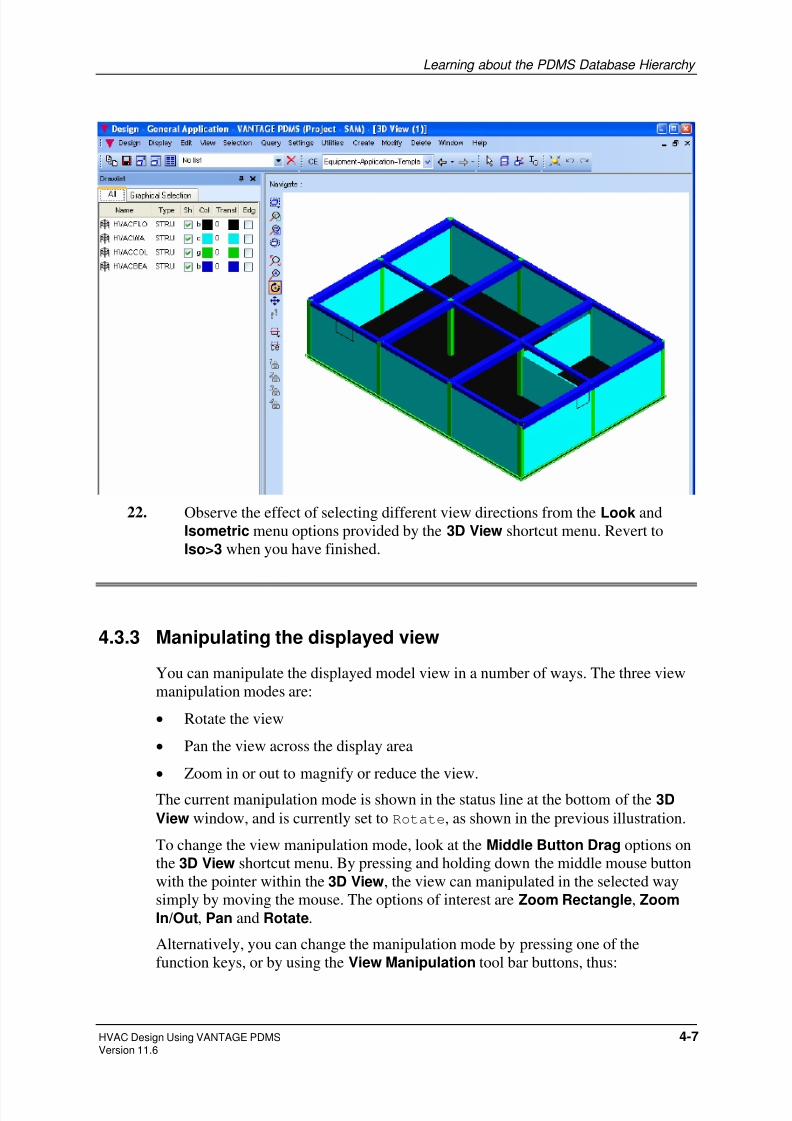
22. Observe the effect of selecting different view directions from the Look and
Isometric menu options provided by the 3D View shortcut menu. Revert to
Iso>3 when you have finished.
4.3.3 Manipulating the displayed view
You can manipulate the displayed model view in a number of ways. The three view
manipulation modes are:
• Rotate the view
• Pan the view across the display area
• Zoom in or out to magnify or reduce the view.
The current manipulation mode is shown in the status line at the bottom of the 3D
View window, and is currently set to Rotate, as shown in the previous illustration.
To change the view manipulation mode, look at the Middle Button Drag options on
the 3D View shortcut menu. By pressing and holding down the middle mouse button
with the pointer within the 3D View, the view can manipulated in the selected way
simply by moving the mouse. The options of interest are Zoom Rectangle, Zoom
In/Out, Pan and Rotate.
Alternatively, you can change the manipulation mode by pressing one of the
function keys, or by using the View Manipulation tool bar buttons, thus:
HVAC Design Using VANTAGE PDMS 4-7 Version 11.6

8/8/2019 Hvac Using Pdms Vol1
http://slidepdf.com/reader/full/hvac-using-pdms-vol1 36/99
Learning about the PDMS Database Hierarchy
F2 or selects Zoom mode
F3 or selects Pan mode
F5 or selects Rotate mode
(Try these selection options and observe the effect on the Middle Button Drag
shortcut menu; a tick appears against the selected option).
You can also choose the view manipulation mode from the options on the
View>Middle Button>Drag menu.
Exercise continues:
23. Select .24. Position the cursor in the view area and hold down the middle mouse button,
then move the mouse slowly from side to side while watching the effect on the
displayed model.
The initial direction of movement determines how the view appears to rotate;
starting with a left or right movement causes the observer’s eye-point to move
across the view.
25. Now release the mouse button, hold it down again and move the mouse away
from you and towards you; this time the observer’s eye-point appears to rotate
up and down around the model.
26. Repeat the rotation operations while holding down the Ctrl key. Note that the
word Fast appears in the status line and that the rate of rotation is increased.
27. Repeat the rotation operations, but this time hold down the key. Note that the
word Slow appears in the status line and that the rate of rotation is decreased.
For an alternative way of rotating the model, try dragging the horizontal and
vertical sliders to new positions along the view borders. You can rotate the
model in this way at any time, regardless of the current manipulation mode.
28. Select .
29. Position the cursor in the view area and hold down the middle mouse button,then move the mouse slowly in all directions.
Note that it is the observer’s eye-point which follows the mouse movement
(while the viewing direction remains unchanged), so that the displayed model
appears to move in the opposite direction to the mouse; in effect, you move the
mouse towards that part of the view which you want to see.
30. Repeat the pan operations while holding down first the Control key (to increase
the panning speed) and then the Shift key (to decrease the panning speed).
31. Select .
4-8 HVAC Design Using VANTAGE PDMSVersion 11.6

8/8/2019 Hvac Using Pdms Vol1
http://slidepdf.com/reader/full/hvac-using-pdms-vol1 37/99
Learning about the PDMS Database Hierarchy
32. Position the cursor in the view area and hold down the middle mouse button,
then move the mouse slowly up and down.
Moving the mouse away from you (up) zooms in, effectively magnifying the
view; moving the mouse towards you (down) zooms out, effectively reducingthe view. Note that these operations work by changing the viewing angle (like
changing the focal length of a camera lens); they do not change the observer’s
eye-point or the view direction.
33. Repeat the zoom operations while holding down first the Ctrl key and then the
key.
34. Position the cursor at the top of one of the corner columns and click (do not
hold down) the middle mouse button. Notice how the view changes so that the
picked point is now at the centre of the view. Whenever you click the middle
button, whatever the current manipulation mode, you reset the centre of
interest. Set the centre of interest to the grille in the front wall, then zoom in fora close-up view. You will find this a very useful technique when making small
adjustments to the design.
35. To restore the original view when you have finished, make sure that your
current element is HVACZONE and click on the Limits CE button, and
reselect View>Isometric>Iso 3.
4.4 Saving the current design and leaving your designsession
Even though you have not yet made any changes to the design database, this is a
suitable point at which to demonstrate how to store the current design at any stage of
a PDMS Design session and how to record your screen layout so that you can start
your next design session in exactly the same state that you ended the current one.
It is good practice regularly to save your work. This avoids the need to start all over
again in the event of loss of work due to an unforeseen interruption, such as a power
failure.
Exercise continues:
36. Update the database to store changes to the design model so far by clicking on
, or selecting Design>Save Work.
37. You should also save your current screen layout and display settings, so that
next time you use the application you can easily pick up your design as it
stands. Do this by selecting
Display>Save>Forms & Display.
HVAC Design Using VANTAGE PDMS 4-9 Version 11.6

8/8/2019 Hvac Using Pdms Vol1
http://slidepdf.com/reader/full/hvac-using-pdms-vol1 38/99
Learning about the PDMS Database Hierarchy
38. You can now leave PDMS and return to the operating system. Do this by
selecting Design>Exit.
Ordinarily, if you had made any changes since your last Save Work operation,
an alert form would ask whether you want to save those changes; this time, youare just asked to confirm that you want to leave PDMS.
39. Click OK.
In the next chapter, you will install a simple HVAC ducting network into the
building model.
4-10 HVAC Design Using VANTAGE PDMSVersion 11.6

8/8/2019 Hvac Using Pdms Vol1
http://slidepdf.com/reader/full/hvac-using-pdms-vol1 39/99
5 Routing a Sequence of HVAC Components
In this chapter you will learn:
• more about how the design data is stored and accessed in PDMS;
• how to route an HVAC network between the grilles in the building walls;
• how to position a selection of HVAC components within the ducting runs.
5.1 HVAC component representation in the catalogue
Each HVAC component is represented in the PDMS catalogue by the following
types of data:
• physical shape
• variables.
5.1.1 HVAC physical shape
The physical shape of a component is defined by a set of geometric primitives.So that a component can be manipulated and linked to adjacent HVAC items, all
principal points needed to define the component position, orientation and
connectivity are identified by uniquely-numbered tags.
These tags, which have both position and direction, are called p-points:
• Each p-point is identified by a number of the format P0, P1, P2 and so on.
• P0 always represents the components origin position.
The principal inlet and outlet points are also identified as p-arrive (PA) and p-leave
(PL). P1 is the same point as p-arrive, and P2 is the same point as p-leave. The
reason for this is that the logical flow statement is not true for HVAC (only Pipingflow).
5.1.2 HVAC variables
The settings of all variables needed to distinguish a component from others with the
same geometry and p-point sets are defined by parameters. The values of these are
defined to suit the specific design requirements.
HVAC Design Using VANTAGE PDMS 5-1Version 11.6
8/8/2019 Hvac Using Pdms Vol1
http://slidepdf.com/reader/full/hvac-using-pdms-vol1 40/99
Routing a Sequence of HVAC Components
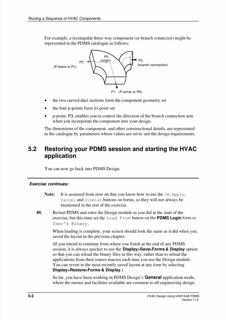
For example, a rectangular three-way component (or branch connector) might be
represented in the PDMS catalogue as follows:
P2
P0P3
P1 (P-arrive or PA)
(P-leave or PL)
(origin)
(branch connection)
• the two curved duct sections form the component geometry set
• the four p-points form its point set
• p-point, P3, enables you to control the direction of the branch connection arm
when you incorporate the component into your design.
The dimensions of the component, and other constructional details, are represented
in the catalogue by parameters whose values are set to suit the design requirements.
5.2 Restoring your PDMS session and starting the HVACapplication
You can now go back into PDMS Design.
Exercise continues:
Note: It is assumed from now on that you know how to use the OK, Apply,
Cancel and Dismiss buttons on forms, so they will not always be
mentioned in the rest of the exercise.
40. Restart PDMS and enter the Design module as you did at the start of the
exercise, but this time set the Load From button on the PDMS Login form to
User’s Binary.
When loading is complete, your screen should look the same as it did when you
saved the layout in the previous chapter.
(If you intend to continue from where you finish at the end of any PDMS
session, it is always quicker to use the Display>Save>Forms & Display option
so that you can reload the binary files in this way, rather than to reload the
applications from their source macros each time you use the Design module.
You can revert to the most recently saved layout at any time by selecting
Display>Restore>Forms & Display.)
So far, you have been working in PDMS Design’s General application mode,
where the menus and facilities available are common to all engineering design
5-2 HVAC Design Using VANTAGE PDMSVersion 11.6

8/8/2019 Hvac Using Pdms Vol1
http://slidepdf.com/reader/full/hvac-using-pdms-vol1 41/99
Routing a Sequence of HVAC Components
disciplines. You can now start the HVAC-specific application, which tailors the
functionality of the PDMS Design module to suit the explicit needs of the
HVAC designer.
41. Change from the General application to the HVAC application, by selectingDesign>HVAC Designer.
The menu bar for the General application is replaced by that for the HVAC
application. The menu bars for both applications look very similar, but the latter
gives you access to options with specific relevance to creating and manipulating
HVAC components.
5.3 Setting HVAC defaults
To minimise the complexity of this exercise, you will set some defaults for yourHVAC Designer exercise:
• a default detailing specification
• the format of the HVAC form
• customised HVAC forms.
5.3.1 Setting a default detailing specification
The constructional details of components that you select from the HVAC catalogue
are determined by the current detailing specification, which is shown on HVAC
application menu bar. The current detailing specification is automatically set toTUTORIAL here.
The TUTORIAL specification gives access to a range of catalogue components that
are suitable for use with this exercise. Although you can, if you wish, choose select a
different specification for each HVAC branch, you will use the same specification
throughout the design exercise.
5.3.2 Choosing the HVAC form format
All the principal functions for creating, positioning, orientating and connectingHVAC elements are available from within a single form, the Heating, Ventilation,
Air Conditioning (HVAC) form (generally referred to as the HVAC form).
The HVAC form has two display formats:
• the brief form, the default, uses drop-down lists to show the elements available
for selection when you are creating a design.
• the full form uses scrollable lists to show the elements available for selection,
and also offers more complex positioning options.
HVAC Design Using VANTAGE PDMS 5-3 Version 11.6
8/8/2019 Hvac Using Pdms Vol1
http://slidepdf.com/reader/full/hvac-using-pdms-vol1 42/99
Routing a Sequence of HVAC Components
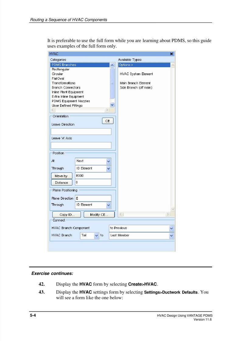
It is preferable to use the full form while you are learning about PDMS, so this guide
uses examples of the full form only.
Exercise continues:
42. Display the HVAC form by selecting Create>HVAC.
43. Display the HVAC settings form by selecting Settings>Ductwork Defaults. You
will see a form like the one below:
5-4 HVAC Design Using VANTAGE PDMSVersion 11.6

8/8/2019 Hvac Using Pdms Vol1
http://slidepdf.com/reader/full/hvac-using-pdms-vol1 43/99
Routing a Sequence of HVAC Components
44. Select Style>Use Full Form… from the HVAC Defaults form menu.
5.3.3 Customising HVAC forms
You can customise the appearance and behaviour of the forms for creating and
modifying HVAC components. This enables you to modify forms to suit, for
example, your preferences, or the type of design work you are doing.
You will apply settings that provide you with the support you need as you learn
about the HVAC application.
Exercise continues:
45. Select Style>Style Options from the HVAC Defaults form menu.
46. On the HVAC Form Style form:
• Set the Show Local Views check box. This displays a small 3D graphical
view showing the current component in its design context.• Set the Local Views Shade check box. This shows local views in colour-
shaded (as opposed to wireline) representation.
• Set the Show Pixmaps check box. This automatically displays diagrams
showing component geometries to help you select items from the catalogue.
• Set the Show Forms check box. This displays a create/modify form
automatically when you add a new component to the design, so that you can
adjust the default dimensions and/or orientation as required.
• Leave the OK/Cancel Forms check box unset. This gives component
create and modify forms Apply and Dismiss buttons (instead of OK and
Cancel buttons), so that they remain available for repeated use until
dismissed explicitly.
47. Click Dismiss.
48. Select Control>Close from the HVAC Defaults form menu.
HVAC Design Using VANTAGE PDMS 5-5 Version 11.6
8/8/2019 Hvac Using Pdms Vol1
http://slidepdf.com/reader/full/hvac-using-pdms-vol1 44/99
Routing a Sequence of HVAC Components
5.4 Creating HVAC administrative elements
You are now ready to create administrative elements which govern the positions of
individual HVAC components within the database hierarchy. The first elements are:
• an HVAC system element
• an HVAC branch element (the branch head).
5.4.1 Creating an HVAC system element
Exercise continues:
49. Make sure that your current element is HVACZONE.
50. In the HVAC form
• From Categories, select PDMS Branches.
• From Available Types, select HVAC System Element.
51. In the displayed Create HVAC form, enter HTESTHVAC in the HVAC Name text
box
52. Click Apply to create the element, then Dismiss to remove the Create HVAC form.
5.4.2 Creating an HVAC branch element
There are two types of HVAC branch element:
• main branch
• side branch.
These differ only in the way they are added to the design:
• a main branch requires you to position and orientate its head explicitly
• a side branch takes its head position and orientation from a branch connection
point (P3) on an existing three-way component.
Your first HVAC branch element will be a main branch element, the branch head.
Exercise continues:
5-6 HVAC Design Using VANTAGE PDMSVersion 11.6
8/8/2019 Hvac Using Pdms Vol1
http://slidepdf.com/reader/full/hvac-using-pdms-vol1 45/99
Routing a Sequence of HVAC Components
53. In the HVAC form, with Categories still set to PDMS Branches, select
Main Branch Element from Available Types.
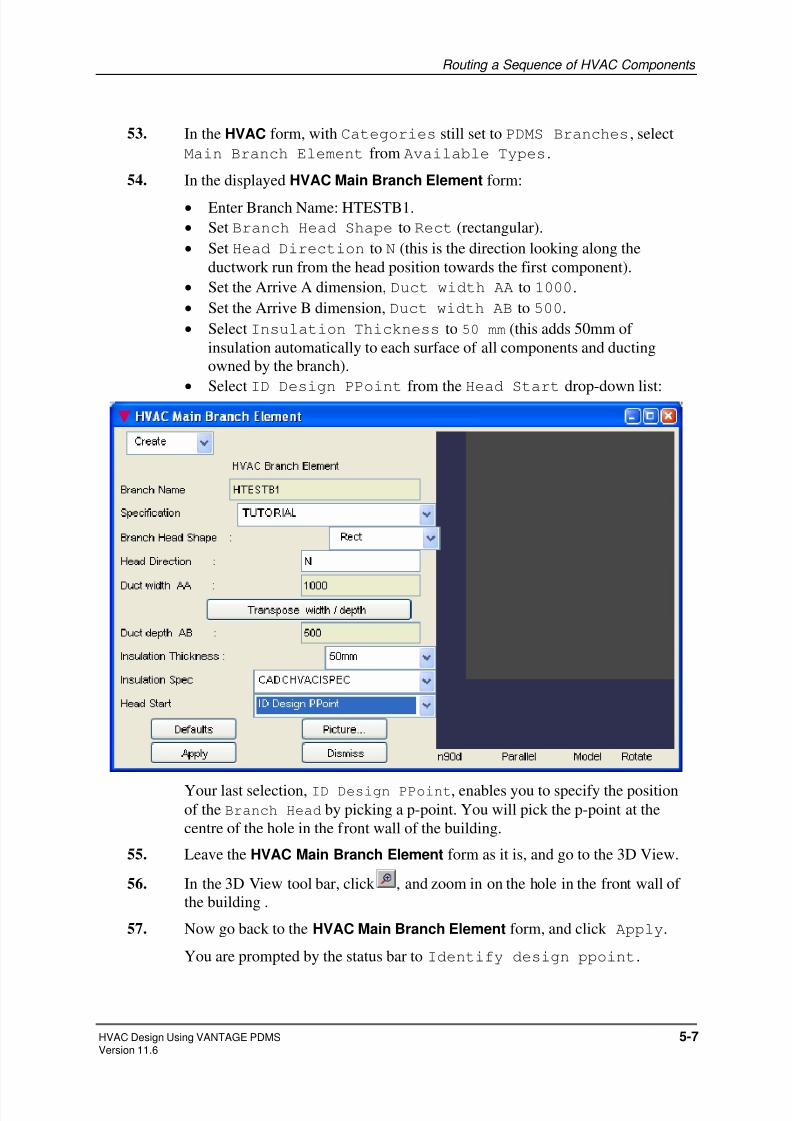
54. In the displayed HVAC Main Branch Element form:
• Enter Branch Name: HTESTB1.
• Set Branch Head Shape to Rect (rectangular).
• Set Head Direction to N (this is the direction looking along the
ductwork run from the head position towards the first component).
• Set the Arrive A dimension, Duct width AA to 1000.
• Set the Arrive B dimension, Duct width AB to 500.
• Select Insulation Thickness to 50 mm (this adds 50mm of
insulation automatically to each surface of all components and ducting
owned by the branch).
•
Select ID Design PPoint from the Head Start drop-down list:
Your last selection, ID Design PPoint, enables you to specify the positionof the Branch Head by picking a p-point. You will pick the p-point at the
centre of the hole in the front wall of the building.
55. Leave the HVAC Main Branch Element form as it is, and go to the 3D View.
56. In the 3D View tool bar, click , and zoom in on the hole in the front wall of
the building .
57. Now go back to the HVAC Main Branch Element form, and click Apply.
You are prompted by the status bar to Identify design ppoint.
HVAC Design Using VANTAGE PDMS 5-7 Version 11.6

8/8/2019 Hvac Using Pdms Vol1
http://slidepdf.com/reader/full/hvac-using-pdms-vol1 46/99
Routing a Sequence of HVAC Components
58. Position the cursor on the edge of the box representing the hole and press and
hold down the left-hand mouse button. The p-points appear as dots. Move the
cursor around the box, continuing to hold down the left-hand mouse button.
Each time the cursor is over a p-point, the p-point is identified in the status bar.
59. Locate p-point P5 in the centre of the southernmost face of the negative box
representing the hole in the wall, and release the mouse button over it.
60. Dismiss the HVAC Main Branch Element form.
You have now defined the branch head.
5.5 Creating HVAC components
Starting at the branch head, you will now build up your HVAC design. You will add
individual components sequentially, and position and orientate each of these as you
proceed.
You will be creating the following overall HVAC configuration:
N
Branchhea d
Branchtail
straight
square bend with deflector vanesfiredamper
radiusedbend
radiusedbend
radiusedbend
firedamper
squareto
round
roundto
square
circularsilencer
th ree-way conn ector
Exercise continues:
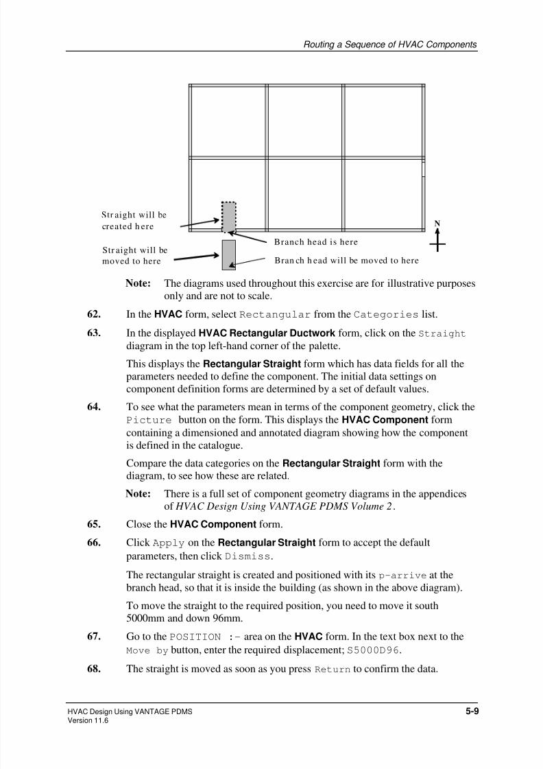
61. The first component required is a rectangular straight, to be aligned with the
hole in the southernmost wall:
5-8 HVAC Design Using VANTAGE PDMSVersion 11.6
8/8/2019 Hvac Using Pdms Vol1
http://slidepdf.com/reader/full/hvac-using-pdms-vol1 47/99
Routing a Sequence of HVAC Components
NStr aight will be
created h ere
Str aight will be
moved to here
Branch head is here
Bran ch h ead will be moved to here
Note: The diagrams used throughout this exercise are for illustrative purposes
only and are not to scale.
62. In the HVAC form, select Rectangular from the Categories list.
63. In the displayed HVAC Rectangular Ductwork form, click on the Straight
diagram in the top left-hand corner of the palette.
This displays the Rectangular Straight form which has data fields for all the
parameters needed to define the component. The initial data settings on
component definition forms are determined by a set of default values.
64. To see what the parameters mean in terms of the component geometry, click thePicture button on the form. This displays the HVAC Component form
containing a dimensioned and annotated diagram showing how the component
is defined in the catalogue.
Compare the data categories on the Rectangular Straight form with the
diagram, to see how these are related.
Note: There is a full set of component geometry diagrams in the appendices
of HVAC Design Using VANTAGE PDMS Volume 2.
65. Close the HVAC Component form.
66. Click Apply on the Rectangular Straight form to accept the default
parameters, then click Dismiss.
The rectangular straight is created and positioned with its p-arrive at the
branch head, so that it is inside the building (as shown in the above diagram).
To move the straight to the required position, you need to move it south
5000mm and down 96mm.
67. Go to the POSITION :- area on the HVAC form. In the text box next to the
Move by button, enter the required displacement; S5000D96.
68. The straight is moved as soon as you press Return to confirm the data.
HVAC Design Using VANTAGE PDMS 5-9 Version 11.6

8/8/2019 Hvac Using Pdms Vol1
http://slidepdf.com/reader/full/hvac-using-pdms-vol1 48/99
Routing a Sequence of HVAC Components
69. You can check that the straight is in the correct position by selecting
Query>Position>Origin from the main menu bar. The position, shown in an
HVAC Command Output window, is:
E 3048 mm S 5125 mm U 3300 mm.
70. To reposition the branch head so that it coincides with the PA of the straight, go
to the drop-down lists in the bottom row of the CONNECT:- area on the HVAC
form:
• Set HVAC Branch to Head
• Set to First Member.
This connects (and therefore repositions) the head of the current branch to the
PA of the first component, the straight (the only branch member so far).
Note: You could have positioned the branch head here when you first created
it, but this would have required you to calculate its coordinatesexplicitly. It is usually easier, as here, to position a new item relative to
an existing design point and then to move it later.
5.5.1 Creating a fire damper
The next step in the construction of your HVAC design is to create a fire damper at
the position where the ducting will pass through the hole in the wall.
Exercise continues:
71. The last operation made the branch head the current element. Each new
component is created immediately after the current component in branch list
order. So to create a component after the straight, you must navigate back to the
straight. To do this, click on the straight in the 3D View.
72. In the HVAC form:
• from Categories, select Inline Plant Equipment
• from Available Types, select Rectangular Fire Damper.
73. On the Rectangular Fire Damper form, name the component FD1. Leave all
parameter settings at their default values, and click Apply to create the fire
damper.
5.5.2 Moving the fire damper
The fire damper is automatically positioned so that its PA is coincident with the PL
of the preceding straight. You will now move it so that it fits within the wall.
5-10 HVAC Design Using VANTAGE PDMSVersion 11.6

8/8/2019 Hvac Using Pdms Vol1
http://slidepdf.com/reader/full/hvac-using-pdms-vol1 49/99
Routing a Sequence of HVAC Components
N
Fire damper
created her e
Fire dampermoved to here
Exercise continues:
74. In the POSITION :- area of the HVAC form, set Through to IDElement.
75. You are prompted to identify an element; pick any part of the southernmost
wall.
The fire damper is moved northward along its axis until it lies in the plane of the
wall, and you are now no longer able to see the fire damper in the 3D View,
because it is hidden within the negative box that represents the hole through the
wall.
The gap between the straight and the fire damper is filled automatically by a
length of implied ducting in the 3D View. Note that implied ducting is notshown as an element in the Design Explorer.
76. Change the 3D View direction to Plan>North, so that your view appears similar
to the diagrams shown here.
5.5.3 Creating a composite component
The HVAC components you have created so far have each been represented by a
single PDMS element. Some HVAC components, however, compositecomponents, are represented by more than one PDMS element.
You must be particularly careful that you are at the correct position in the Design
Explorer when you want to refer to such a component. The next part of the exercise
shows you how composite components are represented within the PDMS hierarchy.
Exercise continues:
77. Use the HVAC form to create a Rectangular Square Bend:
• set Leave Direction to W
HVAC Design Using VANTAGE PDMS 5-11 Version 11.6
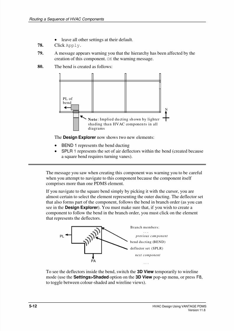
8/8/2019 Hvac Using Pdms Vol1
http://slidepdf.com/reader/full/hvac-using-pdms-vol1 50/99
Routing a Sequence of HVAC Components
• leave all other settings at their default.
78. Click Apply.
79. A message appears warning you that the hierarchy has been affected by the
creation of this component. OK the warning message.
80. The bend is created as follows:
N
PL of bend
Note : Implied du cting sh own by lighter
sha ding tha n HVAC componen ts in alldiagrams
The Design Explorer now shows two new elements:
• BEND 1 represents the bend ducting
• SPLR 1 represents the set of air deflectors within the bend (created because
a square bend requires turning vanes).
The message you saw when creating this component was warning you to be carefulwhen you attempt to navigate to this component because the component itself
comprises more than one PDMS element.
If you navigate to the square bend simply by picking it with the cursor, you are
almost certain to select the element representing the outer ducting. The deflector set
that also forms part of the component, follows the bend in branch order (as you can
see in the Design Explorer). You must make sure that, if you wish to create a
component to follow the bend in the branch order, you must click on the element
that represents the deflectors.
Branch members:
. . . previous com ponent
bend du cting (BEND)
deflector set (SPLR)
next component
. . .
PL
PA
To see the deflectors inside the bend, switch the 3D View temporarily to wireline
mode (use the Settings>Shaded option on the 3D View pop-up menu, or press F8,
to toggle between colour-shaded and wireline views).
5-12 HVAC Design Using VANTAGE PDMSVersion 11.6

8/8/2019 Hvac Using Pdms Vol1
http://slidepdf.com/reader/full/hvac-using-pdms-vol1 51/99
Routing a Sequence of HVAC Components
5.6 Adding more HVAC components to your ductwork
5.6.1 Creating a rectangular radiused bend
Exercise continues:
81. Using the Design Explorer, make sure that the deflector set of the rectangular
square bend (SPLR 1) is your current element.
82. Use the HVAC form to create a Rectangular Radiused Bend:
• set Inside Radius to 100
• set Leave Direction to N
• leave the defaults for all other settings.
83. Click Apply.
N
Radiused bend
5.6.2 Repositioning the rectangular radiused bend
You need to position the new bend in the plane of the westernmost wall.
Exercise continues:
84. Position the new bend in the plane of the westernmost wall by using
POSITION :- Through ID Element on the HVAC form. Pick the wall,
or rather, because you are using a plan view, pick the beam above it.
85. Now move the bend to fit just inside the wall, and downwards so that the
ducting leaving it passes under the beam across the building roof. Enter
POSITION :- Move by E800D150. The result is:
HVAC Design Using VANTAGE PDMS 5-13 Version 11.6

8/8/2019 Hvac Using Pdms Vol1
http://slidepdf.com/reader/full/hvac-using-pdms-vol1 52/99
Routing a Sequence of HVAC Components
N
Duct to pass
under beam
Broken line here shows
components are now misaligned
5.6.3 Creating a rectangular mitred offset
Because you have moved the radiused bend downwards, its inlet (PA) is notvertically aligned with the outlet (PL) of the preceding component. This is
indicated in the 3D View by a broken line between the components, rather than
implied ducting. To correct this problem, you will insert a mitred offset section
between the two components.
Exercise continues:
86. Remember that a new component is always added immediately after the current
element, so navigate back to the deflector set (SPLR1) of the square bend.
87. Create a Rectangular Mitred Offset.
88. PDMS has a powerful facility that can calculate the length and amount of offset
needed to fit the new component automatically into the available space. Simply
click the Fit button on the Rectangular Mitred Offset form. The calculated
data is entered into the parameter data fields: note, for example, that the A
Offset is now set to 150.
You may wish to zoom in close to the mitred offset and view it from different
angles to see how it has been adjusted to fit between the two bends.
5.6.4 Creating a second rectangular radiused bend
Exercise continues:
89. Navigate back to the last component in the branch, the radiused bend.
90. Create a second radiused bend with:
• the default Inside Radius (0.5 means 0.5 x duct width)
5-14 HVAC Design Using VANTAGE PDMSVersion 11.6
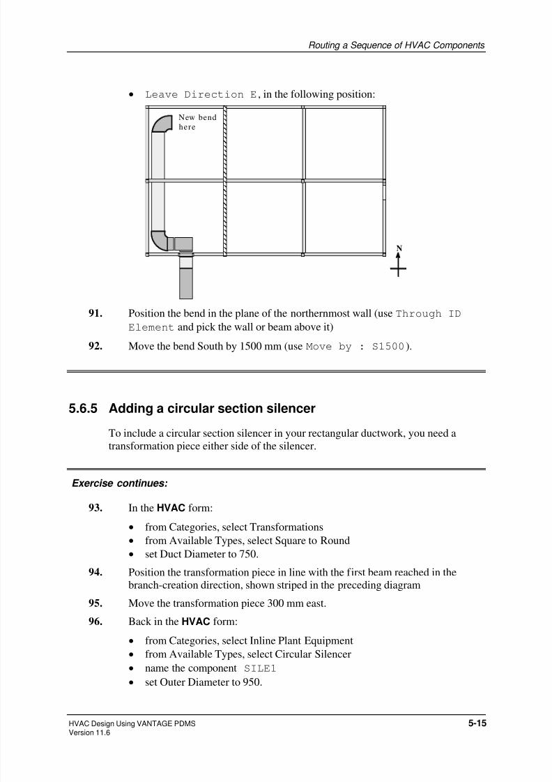
8/8/2019 Hvac Using Pdms Vol1
http://slidepdf.com/reader/full/hvac-using-pdms-vol1 53/99
Routing a Sequence of HVAC Components
• Leave Direction E, in the following position:
N
New bend
here
91. Position the bend in the plane of the northernmost wall (use Through ID
Element and pick the wall or beam above it)
92. Move the bend South by 1500 mm (use Move by : S1500).
5.6.5 Adding a circular section silencer
To include a circular section silencer in your rectangular ductwork, you need a
transformation piece either side of the silencer.
Exercise continues:
93. In the HVAC form:
• from Categories, select Transformations
• from Available Types, select Square to Round
• set Duct Diameter to 750.
94. Position the transformation piece in line with the first beam reached in the
branch-creation direction, shown striped in the preceding diagram
95. Move the transformation piece 300 mm east.
96. Back in the HVAC form:
• from Categories, select Inline Plant Equipment
• from Available Types, select Circular Silencer
• name the component SILE1
•
set Outer Diameter to 950.
HVAC Design Using VANTAGE PDMS 5-15 Version 11.6

8/8/2019 Hvac Using Pdms Vol1
http://slidepdf.com/reader/full/hvac-using-pdms-vol1 54/99
Routing a Sequence of HVAC Components
You will now add another transformation piece to revert back to rectangular
ducting. However, instead of specifying this from first principles, you will
create a copy of the existing transformation piece, and reverse it to achieve the
desired round-to-square result.
97. On the HVAC form, click the Create Copy ID button. When prompted,
pick the square-to-round transformation that you want to copy.
98. On the Square to Round Transformation form, set the Flip Circ/Rect
option to Yes. This interchanges the PA and PL points reversing the
component’s direction.
Your HVAC layout now looks like this:
N
Squareto round
Round to
square
Circularsilencer
5.6.6 Adding a three-way component and terminating the branch
A three-way component enables you to connect one branch to another. You will
need a three-way component so that you can connect a side branch into your existing
main branch later in the exercise.
Exercise continues:
To create a three-way component:
99. In the HVAC form:
• from Categories, select Rectangular
• from Available Types, select Square Threeway
• set Duct Width LA (leave A dimension) to 800
• set Second Width (for the branch connection) to 800
• set Leave Direction to S.
5-16 HVAC Design Using VANTAGE PDMSVersion 11.6

8/8/2019 Hvac Using Pdms Vol1
http://slidepdf.com/reader/full/hvac-using-pdms-vol1 55/99
Routing a Sequence of HVAC Components
You require a gap of 1500 mm between the three-way component and the
preceding component (the round-to-square transformation). The Distance
operation on the HVAC form enables you to do this by allowing you to specify
the gap between the PL of one component and the PA of the next, therebyavoiding the need for you to calculate the movement required to reposition it.
100. Move the three-way component along the branch axis by setting Distance to
1500.
101. You can make sure that the gap is correct; navigate back to the round-to-square
transformation and select Query>Gap to next from the main menu bar.
102. Return to the square three-way component and create a Rectangular
Radiused Bend with default dimensions and Leave Direction East.
103. Align the bend with the hole in the easternmost wall using the Through ID
Element option. Pick the edge of the box outline on this wall.
Note: The current branch direction (the PL direction of the previous
component) was changed to South by the three-way item, so the bend
moves south until it is aligned with the picked element.
104. Create a second Rectangular Fire Damper, give it the name FD2, and
position it through the hole in the easternmost wall.
5.6.7 Defining the branch tail
You complete the definition of your main branch by defining the branch tail.
Exercise continues:
105. Connect the Branch Tail to the fire damper (the last member of the branch):
• Select Tail from the HVAC Branch menu at the foot of the HVAC form.
• Select Last Member.
This uses the same method that you used to connect the branch head in Step 70.)
The final HVAC configuration is:
HVAC Design Using VANTAGE PDMS 5-17 Version 11.6
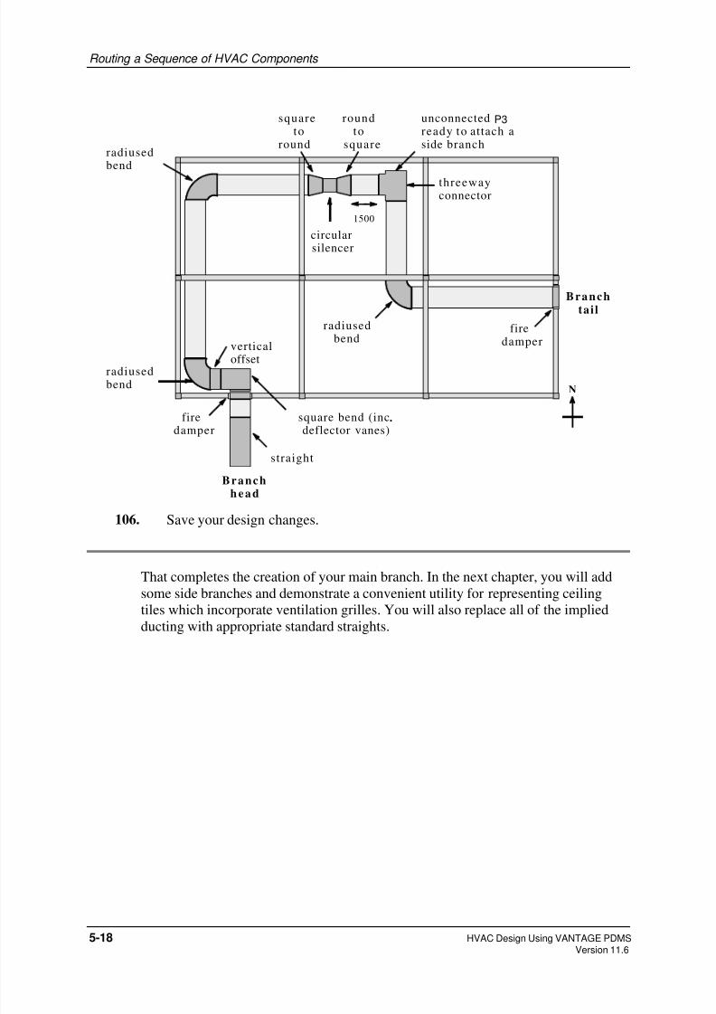
8/8/2019 Hvac Using Pdms Vol1
http://slidepdf.com/reader/full/hvac-using-pdms-vol1 56/99
Routing a Sequence of HVAC Components
N
Branchhe ad
Branchtail
straight
square bend (inc.deflector vanes)
firedamper
verticaloffset
radiusedbend
radiusedbend
radiusedbend
firedamper
squareto
round
roundto
square
circularsilencer
threewayconnector
1500
unconnected P3ready to attach aside branch
106. Save your design changes.
That completes the creation of your main branch. In the next chapter, you will add
some side branches and demonstrate a convenient utility for representing ceiling
tiles which incorporate ventilation grilles. You will also replace all of the implied
ducting with appropriate standard straights.
5-18 HVAC Design Using VANTAGE PDMSVersion 11.6

8/8/2019 Hvac Using Pdms Vol1
http://slidepdf.com/reader/full/hvac-using-pdms-vol1 57/99
Routing a Sequence of HVAC Components
HVAC Design Using VANTAGE PDMS 5-19 Version 11.6

8/8/2019 Hvac Using Pdms Vol1
http://slidepdf.com/reader/full/hvac-using-pdms-vol1 58/99
Routing a Sequence of HVAC Components
5-20 HVAC Design Using VANTAGE PDMSVersion 11.6
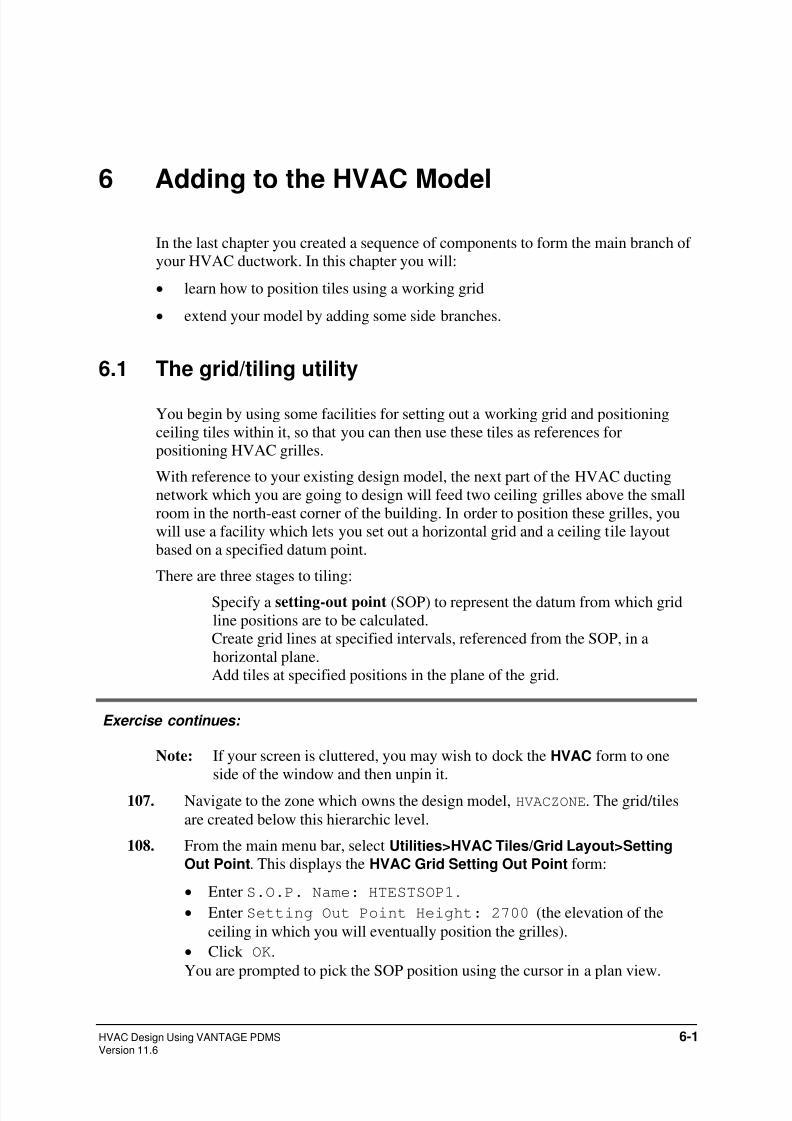
8/8/2019 Hvac Using Pdms Vol1
http://slidepdf.com/reader/full/hvac-using-pdms-vol1 59/99
6 Adding to the HVAC Model
In the last chapter you created a sequence of components to form the main branch of
your HVAC ductwork. In this chapter you will:
• learn how to position tiles using a working grid
• extend your model by adding some side branches.
6.1 The grid/tiling utility
You begin by using some facilities for setting out a working grid and positioning
ceiling tiles within it, so that you can then use these tiles as references for
positioning HVAC grilles.
With reference to your existing design model, the next part of the HVAC ducting
network which you are going to design will feed two ceiling grilles above the small
room in the north-east corner of the building. In order to position these grilles, you
will use a facility which lets you set out a horizontal grid and a ceiling tile layout
based on a specified datum point.
There are three stages to tiling:
Specify a setting-out point (SOP) to represent the datum from which grid
line positions are to be calculated.
Create grid lines at specified intervals, referenced from the SOP, in a
horizontal plane.
Add tiles at specified positions in the plane of the grid.
Exercise continues:
Note: If your screen is cluttered, you may wish to dock the HVAC form to one
side of the window and then unpin it.
107. Navigate to the zone which owns the design model, HVACZONE. The grid/tiles
are created below this hierarchic level.
108. From the main menu bar, select Utilities>HVAC Tiles/Grid Layout>Setting
Out Point. This displays the HVAC Grid Setting Out Point form:
• Enter S.O.P. Name: HTESTSOP1.
• Enter Setting Out Point Height: 2700 (the elevation of the
ceiling in which you will eventually position the grilles).
• Click OK.
You are prompted to pick the SOP position using the cursor in a plan view.
HVAC Design Using VANTAGE PDMS 6-1Version 11.6

8/8/2019 Hvac Using Pdms Vol1
http://slidepdf.com/reader/full/hvac-using-pdms-vol1 60/99
Adding to the HVAC Model
You want to position the SOP at the exact centre of the room’s ceiling. Rather
than trying to pick this point precisely, you will pick a random point in the
ceiling plane as the SOP, and then move this point to the exact position
required.
109. Pick a point.
110. To move this point to the centre of the room, select Position>Explicitly (AT)
from the main menu. Enter the coordinates E15000 N9000 U2700 on the
Explicit Position form (ignore the Positioning Control form).
The SOP appears in the 3D View as a small sphere, and is represented by a
DISH element in the PDMS hierarchy.
111. You will next define a grid in the plane of the ceiling (a horizontal reference
grid) through the SOP datum, with the grid lines spaced out from the SOP in
both directions.Select Utilities>HVAC Tiles/Grid Layout>Grid from S.O.P.. This displays the
HVAC Layout Grid from SOP form.
Leave the East/West and North/South Grid Spacing separations set
to the default of 600.
112. Click OK. You might be prompted to identify the SOP from which the grid line
positions are calculated (unless it is already the current element): if so, pick the
SOP which you have just created. You must now define the horizontal
rectangular area which represents the grid boundaries. You are prompted to pick
first the south-west corner and then the north-east corner in a plan view. Pick
the corresponding corners of the room (the intersections of the beams at these
corners).
Since your room is 6000 x 6000 mm, the 600 mm grid line spacing gives you 10
grid squares in each direction within the ceiling area, like this:
N
= S.O.P .
Pick SWcorner first
Pick NEcornersecond
= Tiles tobe adde d
6-2 HVAC Design Using VANTAGE PDMSVersion 11.6

8/8/2019 Hvac Using Pdms Vol1
http://slidepdf.com/reader/full/hvac-using-pdms-vol1 61/99
Adding to the HVAC Model
Note: If the room were not rectangular, you could build up an overall grid by
using abutting rectangles based on separate setting-out points.
To complete this part of the exercise, you will create two tiles in the ceiling grid
where you want to install HVAC grilles (as shown by the shaded and stripedgrid squares in the preceding diagram).
113. Select Utilities>HVAC Tiles/Grid Layout>Apply Tiles in Grid. This displays
the HVAC Apply Tiles in Grid form.
Leave the East/West and North/South Tile Width dimensions set to
the default of 600. (They do not have to be the same size as the grid squares,
but are usually so in practice.)
114. Click OK.
You are prompted to identify the SOP with the grid for to positioning the tiles.
Even though there is only one, pick the SOP to confirm your intentions.
You are now prompted to identify the locations at which you want to insert
tiles.
115. Pick the grid squares marked and in the above diagram (the picked points
snap to the nearest half tile, so you don’t need to be too precise). Then press the
Escape key to indicate that you have finished adding tiles.
6.2 Creating side branches
You next want to create a side branch which runs from a start point on the main
branch and which passes between the tile positions. You will then add two more side
branches, each running from a point on the first side branch to the tile positions
(remember that you need a separate branch for each length of ducting between two
points).
You will complete the ducting network by adding a fourth side branch, leading to an
angled outlet mesh, from the unconnected arm of the square three-way component.
To start with, you must insert a suitable connector into the main branch so that youhave a point to which you can connect the side branch head.
Exercise continues:
116. Navigate to the existing three-way item. You will insert another branch
connector immediately after it in the branch sequence.
117. If you unpinned it earlier, re-display the HVAC form by hovering over the
HVAC tab.
118. Use the HVAC form to create the next component:
• from Categories, select Branch Connectors
HVAC Design Using VANTAGE PDMS 6-3 Version 11.6

8/8/2019 Hvac Using Pdms Vol1
http://slidepdf.com/reader/full/hvac-using-pdms-vol1 62/99
Adding to the HVAC Model
• from Available Types, select Flat Oval ‘A’ Boot.
• set Boot Width to 610
• set Boot Depth to 152
• set B Offset to 100 • set Boot Direction to E.
119. Click Apply.
N
P3 of boot conn ector
aligned with SO PBoot conn ector with
flat oval side out let
P3
P3
You want the oval ducting to pass along the centreline of the ceiling, so position
the current component so that its outlet is aligned with the SOP datum at the
ceiling’s centre.
(using the Through ID Element facility on the HVAC form):
120. In the HVAC form:
• from Categories, select PDMS Branches
• from Available Types, select Side Branch (off main).
121. From the HVAC Side Branch Element (Connected to ‘Main’) form:
• Set Branch Name to HTESTB1.1 (showing that it is a side branch of
main branch HTESTB1)
• Set Insulation Thickness to 50 mm • Leave Specification set to the current default (the same specification
as the main branch)
• Because you are creating a side branch, it is assumed that you will connect
its head to a free P3 point on an existing component. Set Connect Head
to Branch Connector to show the type of component to which this
connection is made.
• Click OK. When prompted, pick the flat oval boot connector.
Note: You can pick any part of the component; the new branch head will always
be connected to its P3 point.)
6-4 HVAC Design Using VANTAGE PDMSVersion 11.6

8/8/2019 Hvac Using Pdms Vol1
http://slidepdf.com/reader/full/hvac-using-pdms-vol1 63/99
Adding to the HVAC Model
122. Create a Flat Oval Straight as the first member of the new side branch.
Set its Width Direction to N.
You are now going to create two circular boot connectors from which to route
outlets to the two tile positions. You will create these and position them before you create the straight to which they are connected, so that the boots can be
positioned relative to the tiles and the length of the straight can then be adjusted
to suit the boot positions.
123. Make the oval straight as current element.
124. In the HVAC form:
• from Categories, select Branch Connectors
• from Available Types, select Circular Boot
• set Boot Diameter to 150
• set Inner Extension to 76 • set Dist from Leave to 100
• leave Boot Direction set to N.
This boot is positioned 100 mm back from the PL of the straight on which it is
mounted (which is only implied at this stage).
125. Move the boot so that it is aligned through the northernmost tile (shown as in
the diagrams).
126. Create a second circular boot as follows:
• from Categories, select Branch Connectors
• from Available Types, select Circular Boot
• set Boot Diameter to 150
• set Inner Extension to 76
• set Dist from Leave to 700
• set Boot Direction to S.
This Dist from Leave dimension positions the boot 700 mm back from the
PL of the previous boot. Since the previous boot was set back 100 mm from its
PL, the difference between the boot positions corresponds to the 600 mm offset
between the two tile positions. The result is as follows:
HVAC Design Using VANTAGE PDMS 6-5 Version 11.6

8/8/2019 Hvac Using Pdms Vol1
http://slidepdf.com/reader/full/hvac-using-pdms-vol1 64/99
Adding to the HVAC Model
N
100
700
ovalboot
first circular boot
second circula r boot
PLs of both
circular boots
are here
main
branch
sidebranch
straight
tile
tile
You can now replace the implied ducting between the circular boots with a
straight component. Because the boots are subcomponents, you must first
navigate back to the existing straight in this side branch.
127. Navigate back two positions (to STRT1 in HTESTB1.1) in the Design
Explorer.
128. Create a second Flat Oval Straight, and use the Fit button to achieve
the required length between the PL of the first straight and the PL of each
circular boot.
The calculated Length is 2525.
129. To complete this first side branch, add a cap to close the end of the last straight;
navigate to the last component of HTESTB1.1 in the Design Explorer (the
southernmost circular boot) and create a Flat Oval Cap End.
(Remember that the PL of this boot is as shown in the above diagram, and not
within the boot volume itself, so that the cap should be positioned correctly and
appear in the correct list order.)
130. Connect the HVAC Branch Tail to the Last Member of the branch (the
cap).
Your second side branch will run from the northernmost circular boot to a grillein the adjacent tile.
131. Navigate to the first side branch (HTESTB1.1) and create a new side branch
named HTESTB1.1.1 with 50 mm insulation thickness. Connect the head of
the new side branch to the circular boot connector.
132. Create a Circular Straight with Length set to 750.
133. To see what types of leave joint are available, click the Choose button next to
the Leajoint field. From the resulting Choose Joint form, select Male
Socket & Spigot Joint and click OK. The Leajoint field is updated
to show MALE.
6-6 HVAC Design Using VANTAGE PDMSVersion 11.6

8/8/2019 Hvac Using Pdms Vol1
http://slidepdf.com/reader/full/hvac-using-pdms-vol1 65/99
Adding to the HVAC Model
134. Create a Circular Internal Damper with default settings.
135. Create a Circular Flexible Bend with its Leave Direction set to
D (down). Position the bend so that it is aligned through the appropriate tile.
(You will adjust the dimensions of this bend later in the exercise.)
136. Use the HVAC form to create a circular to rectangular spigot box:
• from Categories, select Transformations
• from Available Types, choose a circular to rectangular spigot box by
selecting Spigot Box.
Set the following parameters:
• duct width LA = 300
• duct depth LB = 300
• Rectangular Box Height = 75 • Circ Extension = 50
• Circ Jnt = MALE.
137. From the Inline Plant Equipment category, create a Rectangular
Grille in line. Set the parameters as follows:
• Name = GRIL1
• End width = 400
• End depth = 400
• Grille Length = 50
• ‘A’ Extension = 0.
You want the grille to fit within the tile volume, so set the Position At
option button on the HVAC form to ID Element and, when prompted, pick
the tile. The origin of the grille is positioned at the origin of the tile.
Note: At this stage the PL of the spigot box and the PA of the grille have
become misaligned, so you see a broken line between them rather than
a length of implied ducting.)
Having positioned the grille correctly, you will now go back along the current
side branch and adjust the other components to fit, starting with the spigot box,
which you will position directly on top of the grille138. Navigate to the spigot box (PLEN 1 in the Design Explorer).
139. Select Position At Next from the HVAC form positioning options.
140. Navigate to the flexible bend and click the Modify CE button on the HVAC
form so that you can adjust the dimensions of the flexible bend so that it fits
correctly between the internal damper (at its PA) and the spigot box (at its PL).
141. Click the Fit button on the Circular Flexible Bend form to recalculate the
dimensions necessary for a correct fit. (The calculated Arrive Extension
becomes 120 and the Leave Extension 225.)
142. Complete the definition of the side branch by connecting its tail to the grille.
HVAC Design Using VANTAGE PDMS 6-7 Version 11.6

8/8/2019 Hvac Using Pdms Vol1
http://slidepdf.com/reader/full/hvac-using-pdms-vol1 66/99
Adding to the HVAC Model
Looking towards the west, the side branch HTESTB1.1.1 now looks like this:
cross-section of
oval side branch/HTESTB1.1 circular boot
connector
circular straight
control dam perinside straight
flexible bend
spigot box
grille
Head
Tail
143. Use the method given above to create a similar side branch, named
HTESTB1.1.2, from the second circular boot to a grille (GRIL2) positioned
in the other tile. (Remember to navigate up to the level of branch HTESTB1.1
first.)
The overall layout of the HVAC ducting in the vicinity of the room now looks
like this (the different shades in this diagram show the branch hierarchy):
N
main branch
/HTESTB.1
s ide branch/HTESTB1.1 s ide branch
/HTESTB1.1.1
s ide/HTESTB1.1.2
four th side bran ch will go her e
You can now complete the network by connecting an angled outlet grille to theside arm of the square three-way component (top left in the preceding diagram).
To do so, you must create a fourth side branch.
144. Navigate to the three-way connector.
145. Create a side branch named HTESTB1.2 with insulation thickness 50mm.
Set the Connect Head to option button on the HVAC Side Branch
Element form to Threeway Item and, when prompted, pick the three-way
component.
146. Create a Rectangular Radiused Bend.
6-8 HVAC Design Using VANTAGE PDMSVersion 11.6

8/8/2019 Hvac Using Pdms Vol1
http://slidepdf.com/reader/full/hvac-using-pdms-vol1 67/99
Adding to the HVAC Model
147. Because you want the bend to turn in the B direction (click the Picture button
for clarification), click the Transpose width/depth button. The Duct
width AA becomes 500 and the Duct depth AB becomes 800.
148. Set the Angle to 135, the Inside Radius to 100, and the LeaveDirection to D.
149. Create a Rectangular Radiused Splitter which fits inside the bend
(it is a subcomponent of the bend). Set the Splitter Radius to 200. If you
are using a colour-shaded view, switch to wireline mode (Graphics>Shaded or
F8 key) to see the splitter.
150. Create a Rectangular Mesh End, using default settings, to complete the
branch. Connect the branch tail to the last member in the usual way.
This side branch now has the following configuration (looking towards the
East):
135°radiused
bend
radiusedsplitter
mesh end
main branch
square
threeway
Head
Tail
To complete the network, you will insert two sets of air turning vanes into the
square three-way component to control the air flows (similar to those which yousaw in the square bend).
151. Navigate to the square three-way component and switch to wireline view (if not
already set) so that you can see what happens next.
152. Create the first set of Rectangular Turning Vanes. Change the Duct
Width AA to 500 and leave the other settings at their defaults. Note in
particular that the Leave Throat is 150 and that the Direction
towards leave radio button is selected.
153. Create a second set of Rectangular Turning Vanes. This time set the
Duct Width AA to 500, the Leave Throat to 650 and select theDirection opposite leave option button.
The result, and the significance of the settings used, are illustrated in the
following diagram:
HVAC Design Using VANTAGE PDMS 6-9 Version 11.6
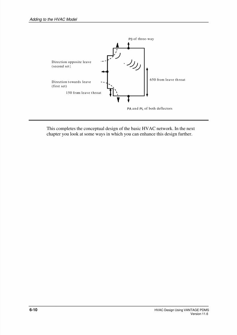
8/8/2019 Hvac Using Pdms Vol1
http://slidepdf.com/reader/full/hvac-using-pdms-vol1 68/99
Adding to the HVAC Model
PA and PL of both deflectors
P3 of three-way
150 from leave t hroat
650 from leave th roat
Direction opposite leave
(second set )
Direction t owards leave
(first set)
This completes the conceptual design of the basic HVAC network. In the next
chapter you look at some ways in which you can enhance this design further.
6-10 HVAC Design Using VANTAGE PDMSVersion 11.6
8/8/2019 Hvac Using Pdms Vol1
http://slidepdf.com/reader/full/hvac-using-pdms-vol1 69/99
7 Completing the Design
In this chapter you will look at some facilities for enhancing the basic HVAC design
model. The main features described are:
• Automatic replacement of implied ducting in gaps by catalogue straights.
• Automatic addition of stiffening flanges to ductwork items.
• Automatic item numbering of HVAC components.
7.1 Filling ductwork gaps automatically
When you created the main branch, HTESTB1, you concentrated on specifying
components with specific functions, such as bends, side connection points, silencers
and dampers. Most of the gaps between these components were left undefined and
were filled by lengths of implied ducting to complete the representation shown in the
3D View.
To enable the design to be prefabricated, it is necessary to specify the fixed lengths
of ductwork (ductwork straights) required between these components, so that a full
material take-off list can be generated. The HVAC application is able to calculate
the optimum combination of standard and non-standard straights needed to fill each
gap and then create the corresponding components in the design database
automatically.
Exercise continues:
154. Navigate to the main branch HTESTB1.
155. To identify what gaps exist in the branch, select Utilities>Autofill with
Straights>Show Gaps.
156. Click Apply on the Highlight Implied Ductwork form.
For each gap in the named branch, the scrollable list area of the form shows the:
• location (the preceding component)
• length
• calculated combination of straights needed to fill it.
All corresponding lengths of implied ducting are highlighted simultaneously in
the 3D View.
The HTESTB1 list shows seven gaps:
HVAC Design Using VANTAGE PDMS 7-1Version 11.6

8/8/2019 Hvac Using Pdms Vol1
http://slidepdf.com/reader/full/hvac-using-pdms-vol1 70/99
Completing the Design
Compare this list with the items highlighted in the 3D View:
7-2 HVAC Design Using VANTAGE PDMSVersion 11.6

8/8/2019 Hvac Using Pdms Vol1
http://slidepdf.com/reader/full/hvac-using-pdms-vol1 71/99
Completing the Design
157. Make sure you are still at HTESTB1, then select Utilities>Autofill withStraights>Fill Gaps.
This displays the form Autofill with Straights.
158. Click Apply.
A list of all identified gaps, is again displayed as before, but this time the
specified straight lengths are created automatically to replace the implied
ducting. Look at the Design Explorer to see the new elements.
159. To make sure that the autofilling operation was carried out correctly, repeat
steps 155 and 156.
The message No Gaps To Show confirms this. There is no need to dismiss
the form immediately because you still need to make sure that there are no gaps
in any of the four side branches.
160. To do so, navigate to each in turn, click the CE button at the top of the
Highlight Implied Ductwork form, then click the Apply button. In each case
you should see the No Gaps To Show message. (If not, go back and correct
any errors in your design before proceeding.)
HVAC Design Using VANTAGE PDMS 7-3 Version 11.6
8/8/2019 Hvac Using Pdms Vol1
http://slidepdf.com/reader/full/hvac-using-pdms-vol1 72/99
Completing the Design
7.2 Adding stiffening flanges
PDMS provides a utility for calculating the optimum numbers and positions of
stiffening flanges needed to support ductwork items. The configuration of theflanges is tailored to suit the component geometry in each case. You can then create
and position such flanges automatically.
Note that, in the branch membership hierarchy, they are treated as subcomponents of
the straight.
Exercise continues:
161. Add flanges to your ductwork in branch order, starting at the branch head;
navigate to the first straight in the main branch (the southernmost straight) tomake it the current element.
162. Use the HVAC form to calculate the number of stiffeners needed for this length
of ducting:
• from Categories, select Rectangular
• from Available Types, choose Stiffening.
The stiffening requirements are calculated, and displayed in the Rectangular
Stiffening form. As you can see, PDMS calculates that this component has a
Spec Requirement of 5 stiffening flanges.
163. To create all five stiffening flanges, click the Apply the Spec Requirement button. The flanges are created and positioned automatically.
164. Navigate to the next straight and stiffen it in the same way; this straight is
shorter, and requires only four flanges.
165. Proceeding along the branch, add stiffeners in turn to the:
• square bend
• mitred offset
• radiused bend.
The stiffening flanges are configured to suit each different component shape.
Note: Different shading identifies individual components; heaviest lines
show flanges joining components together:
7-4 HVAC Design Using VANTAGE PDMSVersion 11.6

8/8/2019 Hvac Using Pdms Vol1
http://slidepdf.com/reader/full/hvac-using-pdms-vol1 73/99
Completing the Design
Nfirst straight
(5 stiffeners)
second stra ight
(4 stiffeners)
square bend
(4 stiffeners)
fire damper
radiused bend
(2 stiffeners)
mitred vertical offset
(1 stiffener)
7.3 Automatic item numbering and naming
The item numbering facility automatically allocates sequential item numbers to all
HVAC components and gives each item a name of the format / PREFIXnumber ,where /PREFIX is a user-definable string and number is the allocated number.
Subcomponents (air deflectors, stiffening flanges and so on) are numbered as
decimalised subsets of their owning components.
Inline plant items, which are usually named, do not have their names changed.
Exercise continues:
166. To autonumber all HVAC items in your current design model, navigate to the
owning HVAC element, HTESTHVAC.
167. Select Utilities>Automatic Itemising from the main menu. This displays the
HVAC Itemising form:
• enter Naming Prefix: /HTEST/ITEM
• leave Start Number set to 1
• Click Apply.
The HVAC Command Output window that is displayed, lists all HVAC items
and their allocated numbers.
When you compare the entries in this itemising list with those in the Design
Explorer, you can see that each item (except any inline component) is now
HVAC Design Using VANTAGE PDMS 7-5 Version 11.6

8/8/2019 Hvac Using Pdms Vol1
http://slidepdf.com/reader/full/hvac-using-pdms-vol1 74/99
Completing the Design
named in the Design Explorer using the specified prefix / HTEST/ITEM
suffixed by the item number. For example, the first two straights in the main
branch, and their stiffening flange subcomponents, appear as follows (the
numbers like =15312/160 and so on are internal database reference numbers,which you can ignore):
7.4 Finishing off design details
You can now complete design details for the ductwork straights you have recently
created to replace implied ducting. To do this, you will:
• modify joint types to suit the final design
• insert an access panel into the side of a length of ducting.
7-6 HVAC Design Using VANTAGE PDMSVersion 11.6

8/8/2019 Hvac Using Pdms Vol1
http://slidepdf.com/reader/full/hvac-using-pdms-vol1 75/99
Completing the Design
7.4.1 Modifying joint types
When the lengths of implied ducting leading to the two fire dampers were replaced
with straight components, the connecting joints will have been assumed to remain asdefault flanged joints. In fact, the fire dampers require raw edge joints, such that the
ducting simply fits over the damper inlet and outlet.
Exercise continues:
The inlet joint for the damper is, in both cases, the leave joint for the straight
that precedes the damper.
168. To modify either one of these joints, navigate to the preceding straight.
169. On the HVAC form, click the Modify CE button. On the resultingRectangular Straight form (in Modify mode), click the Leajoint Choose
button and, from the Choose Joint form, select Raw Edge Joint, slip
over 40mm. The leave joint field is now set to RE40.
170. Click Apply.
171. Use the same procedure to modify the inlet to the other fire damper.
172. To modify the outlet joint between the first damper and the square bend (the
arrive joint of the bend), navigate to the bend and click Modify CE. On the
resulting Rectangular Square Bend form, click the Arrjoint Prev button. The
arrive joint field is set to RE40 by automatic reference to the previous
component, namely the fire damper. Apply the change.
To modify the outlet from the second damper, connect the branch tail to the last
member in the usual way.
7.4.2 Inserting an access panel
The final component of your HVAC ducting network is an access panel in the
end straight of the main branch.
173. You will now insert an access panel, whose catalogue definition includes a
predefined working volume, into the side of the last straight. (The reason for
doing this will become clear when you look at clash checking in the next
chapter.)
174. Navigate to the appropriate straight. (This is the short one, named
HTEST/ITEM21 by the itemising utility, and connected to fire damper FD2.)
175. Use the HVAC form to create the access panel:
• from Categories, select Rectangular
• from Available Types, choose Access Panel
• from Select Size options, which show all panel sizes available in the
catalogue, select 400x350
HVAC Design Using VANTAGE PDMS 7-7 Version 11.6

8/8/2019 Hvac Using Pdms Vol1
http://slidepdf.com/reader/full/hvac-using-pdms-vol1 76/99
Completing the Design
• click the first Transpose width/depth button to give the required
configuration (350 W x 400 H).
176. Click Apply.
When created, the panel appears in the 3D View as a rectangular plate standing
slightly proud of the ducting surface. In the next section you will look at its
hidden geometry in more detail.
177. Run the automatic itemising utility again so that the access panel is included in
the item list.
7.5 Changing the view representation
You have already seen how to control which design elements appear in the 3D View
by using the Drawlist to add or remove items as required. You have also seen how
to control the viewable volume and the viewing direction by using the options from
the 3D View’s shortcut menu. You will now see how you can further refine the view
by specifying different levels of detail for the items being displayed.
Exercise continues:
178. The amount of detail shown in the 3D View for different types of component iscontrolled by the current representation settings. To see what these settings are,
select Settings>Graphics>Representation from the main menu. This displays
the Representation form. You will look at just two of its options here.
The geometric representation of a catalogue component can include, in addition
to its normal physical shape, an obstruction volume which represents the space
around the component needed for maintenance or operational access. The
access panel created in Step 175 is an example of such an item. To see what the
obstruction volume looks like, set the Obstruction option to Solid on the
Representation form and click OK.
Zoom in close to the access panel and see how its appearance has changed. Theeffect, exaggerated here for emphasis, is as follows:
accesspanel
obstruction
volume
7-8 HVAC Design Using VANTAGE PDMSVersion 11.6

8/8/2019 Hvac Using Pdms Vol1
http://slidepdf.com/reader/full/hvac-using-pdms-vol1 77/99
Completing the Design
To reset the normal view, redisplay the Representation form and set
Obstruction to Off and click OK.
179. The holes through the walls, where the fire dampers are situated, may be shown
either as boxes (specially shaded to show that they represent negative boxes,holes) or as true holes. So far you have used the shaded box representation so
that you could pick the holes graphically to identify them. To switch to a more
realistic representation, select Holes Drawn and click Apply.
Look carefully at each hole in turn. You are now able to see the ducting and fire
dampers where they penetrate the walls.
That completes the introduction to the basic HVAC routing operations. In the
following parts of the exercise you will look at some ways of checking the design
model and outputting some design data derived from the database settings
HVAC Design Using VANTAGE PDMS 7-9 Version 11.6

8/8/2019 Hvac Using Pdms Vol1
http://slidepdf.com/reader/full/hvac-using-pdms-vol1 78/99
Completing the Design
7-10 HVAC Design Using VANTAGE PDMSVersion 11.6

8/8/2019 Hvac Using Pdms Vol1
http://slidepdf.com/reader/full/hvac-using-pdms-vol1 79/99
8 Checking and Outputting Design Data
In this chapter you learn about:
• methods of checking for errors and inconsistencies in the HVAC layout
• checking for clashes (spatial interferences) between design elements
• how to output a design data report derived from the piping model
• how to generate an isometric plot.
Note: Most of these facilities are available from all Design applications, so you
can readily check and output data from any combination of designdisciplines.
8.1 Querying data settings
First, you will look at some ways in which you can query specific data settings as
you build up the design model, so that you can check detailed design points at any
stage.
Exercise continues:
180. Navigate to the square three-way component and then select Query>Item
Details>Brief Description from the main menu. This displays the summary
showing the component’s type, key dimensions and joint specifications, like
this:
Repeat this operation for some other components (and subcomponents).
181. Navigate to the first (southernmost) straight and select Query>Item
Details>Item Number. The resulting output, labelled Item Number 1, is
appended to the output from the previous query. Compare the result with the
data illustrated at the end of Section 8.4.
HVAC Design Using VANTAGE PDMS 8-1Version 11.6

8/8/2019 Hvac Using Pdms Vol1
http://slidepdf.com/reader/full/hvac-using-pdms-vol1 80/99
Checking and Outputting Design Data
182. At any component, select Query>Item Details>Insulation Depth. The
resulting output should always say Insulation 50 mm, since you specified
this insulation thickness when you created each branch.
183. Use the following Query options for several different types of component:
Query>Position>Origin
Query>Position>Position PA
Query>Position>Position PL
Compare the results with the catalogue definitions for the corresponding
components, as illustrated in Appendix C of Volume 2 of HVAC Design Using
VANTAGE PDMS.
8.2 Checking for design data inconsistencies
The data consistency checking utility reports the following types of occurrence (and
other similar errors) in the design:
• Branch head or tail reference not set
• Branch head or tail reference type not valid
• Adjoining components have incorrectly ordered PA and PL points; for example,
one component may have been flipped while its neighbour was not
• Distance between a component and a connected neighbour, or between a
component and the branch head or tail, is not valid
• Neighbouring connected components, or a component and the branch head or
tail, have their PA/PL misaligned
• Arrive or leave joint has wrong connection type
Exercise continues:
184. To check your design for data consistency errors, select Utilities>Data
Consistency. You will see a Data Consistency Check form. You use the
default settings for all data checking operations.
You can send the error report either to your screen or to a file. You will view it
on screen, so select Output: Screen.
The Check: list lets you specify how much of the design model you want to
check in a single operation. You will check each branch separately, so select
Branch from the list.
185. Navigate to any component in the main branch HTESTB1 and click Apply to
initiate the data checking process.
8-2 HVAC Design Using VANTAGE PDMSVersion 11.6

8/8/2019 Hvac Using Pdms Vol1
http://slidepdf.com/reader/full/hvac-using-pdms-vol1 81/99
Checking and Outputting Design Data
The resulting diagnosis is shown in the scrollable text area at the bottom of the
form.
These two messages remind you that the head and tail of the branch have not
been explicitly terminated and are not connected to any external items. (Each
branch end would normally be connected to, say, an air handling unit or to some
other ductwork in an adjacent design zone.)
186. Repeat the check for each of the side branches in turn (for the purposes of thisexercise, ignore any messages which you receive as a result).
Note: For the purposes of this exercise, you can ignore any messages that may
appear.
It is good practice to run a data consistency check whenever you have created or
modified any significant amount of the design, typically before you choose
Design>Save Work.
HVAC Design Using VANTAGE PDMS 8-3Version 11.6
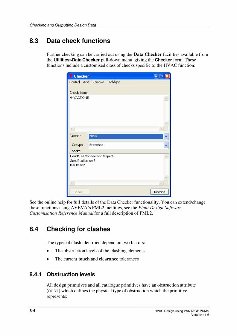
8/8/2019 Hvac Using Pdms Vol1
http://slidepdf.com/reader/full/hvac-using-pdms-vol1 82/99
Checking and Outputting Design Data
8.3 Data check functions
Further checking can be carried out using the Data Checker facilities available from
the Utilities>Data Checker pull-down menu, giving the Checker form. Thesefunctions include a customised class of checks specific to the HVAC function:
See the online help for full details of the Data Checker functionality. You can extend/change
these functions using AVEVA’s PML2 facilities, see the Plant Design Software
Customisation Reference Manual for a full description of PML2.
8.4 Checking for clashes
The types of clash identified depend on two factors:
• The obstruction levels of the clashing elements
• The current touch and clearance tolerances
8.4.1 Obstruction levels
All design primitives and all catalogue primitives have an obstruction attribute
(OBST) which defines the physical type of obstruction which the primitive
represents:
8-4 HVAC Design Using VANTAGE PDMSVersion 11.6

8/8/2019 Hvac Using Pdms Vol1
http://slidepdf.com/reader/full/hvac-using-pdms-vol1 83/99
Checking and Outputting Design Data
• A hard obstruction (OBST=2) represents a rigid and impenetrable object, such
as a steel beam or a plant vessel.
• A soft obstruction (OBST=1) represents a volume which is not solid but which
needs to be kept clear for access.
• Any primitive with OBST=0 represents a freely accessible volume and is
ignored for clash checking purposes.
8.4.2 Extent of clashing
As well as distinguishing between hard and soft clashing items, the checking utility
recognises three categories of clash between them, depending on how far the two
primitives intrude on each other’s allocated space. These categories are:
• A physical clash: the primitive volumes overlap by more than a specifiedamount. This usually means that a definite interference exists.
• A touch: the primitives either overlap by less than the amount needed to cause a
clash or are separated at their closest point by less than a specified distance.
This may simply mean that one item is resting upon another as intended, or it
may indicate a problem.
• A clearance: the primitives are separated at their closest point by more than the
amount necessary to constitute a touch but less than a specified clearance
distance. This represents a near miss, which you may want to investigate.
These three classes are illustrated below for the clash specifications:Touch limits: 5mm overlap to 2mm gap
Clearance limit: 8mm
so that the following criteria apply:
• If the items overlap by more than 5mm, a clash is reported
• If the items overlap by less than 5mm, a touch is reported
• If the items do not overlap but are separated by less than 2mm, a touch is
reported
• If the items are separated by more than 2mm but less than 8mm, a clearance is
reported
• If the items are separated by more than 8mm, no interference is found
HVAC Design Using VANTAGE PDMS 8-5Version 11.6

8/8/2019 Hvac Using Pdms Vol1
http://slidepdf.com/reader/full/hvac-using-pdms-vol1 84/99
Checking and Outputting Design Data
overlap > 5mm overlap < 5mm 2mm < gap < 8mm
a physical clash touches a clearance
gap < 2mm
8.4.3 The clash detection process
Each element which is to be checked for clashes has its own geometry checked
against that of all other elements which are specified by a current obstruction list.
Items which are not in the obstruction list are ignored during the clash checkingoperations. By default, the obstruction list includes all elements in the database, so
that each element to be clash checked is tested against every other element. To
control the amount of checking carried out in a large database, you can restrict the
obstruction list to a few specific elements and/or you can specify a 3D volume (the
clash limits) within which the clash checking is to be confined.
To highlight the locations where clashes are found, the clashing and obstruction
items are shown in contrasting colours in the graphical view (two shades of red, by
default).
Exercise continues:
187. You will use the default values for all clash checking settings. To see what these
are, select Settings>Clasher>Defaults to display the Clash Defaults form.
Think about the meaning of each setting shown (refer to the preceding
introduction); then Cancel the form.
188. You will check all your HVAC components for clashes against the building
structure. The default obstruction list (all elements in the current design
database) includes both structural and HVAC items. To edit this, select
Settings>Clasher>Obstruction>List. This displays the Add/Remove
Obstruction Items form. Remove all current entries (if any) from theObstruction List by selecting All from the Remove list and then
clicking Remove. Then Add the structural design data only (HVACFLOOR,
HVACROOF, HVACWALLS, HVACCOLS and HVACBEAMS). (To see these first
click HVACZONE in the left-hand list. See the online help for full details of
using the Add/Remove Obstruction Items form.)
189. Navigate to the element holding all the HVAC design data which you want to
check (/ HTESTHVAC) and select Utilities>Clashes. This displays the Clash
Display form. The left-hand side of this form controls the clash checking
process; the right-hand side consists of a 3D view in which you can look in
detail at any clashes diagnosed. Select Control>Check CE from the form’s left-
8-6 HVAC Design Using VANTAGE PDMSVersion 11.6

8/8/2019 Hvac Using Pdms Vol1
http://slidepdf.com/reader/full/hvac-using-pdms-vol1 85/99
Checking and Outputting Design Data
hand menu bar to run the clash checking process and, when completed, study
the Clash List which shows any clashes found.
In your case this should show one clash only, with the description
1 SH CLASH HACC 1 of BRAN /HTESTB1
This identifies a soft-hard (SH) clash between the obstruction volume associated
with the access panel (which you added in Step 175 and which is illustrated in
Step 178) and the adjacent wall. To see this properly in the form’s 3D view, set
the graphics representation to show obstruction volumes (as explained in Step
178) and zoom in close to the access panel. Notice how the clashing items are
highlighted in shades of red (if they are not, repeat the Check CE operation to
regenerate the clash data). See the online help for full details of using the Clash
Display form.
190. To see more information about the clash, select Query>Clash>Detail from the
Clash Display form’s menu bar. This displays the Clash Detail form as
follows:
Note: If the Auto Clash button (in the main menu bar) is in the ‘on’ state ( ),
each new element that you create is checked immediately for clashes as the
design is built up. This can slow down progress when you are adding many
new elements, but is very useful when you want to add a few new items to
an existing design which has already been checked for clashes.
Obstruct ion
volume for
Acc ess Panel
Adjacent Wal l
Loca t ion o f
c lash
HVAC Design Using VANTAGE PDMS 8-7Version 11.6
8/8/2019 Hvac Using Pdms Vol1
http://slidepdf.com/reader/full/hvac-using-pdms-vol1 86/99
Checking and Outputting Design Data
8.5 Generating a data output report
This section describes two ways of outputting design data derived from your design
model.
• generating a tabulated report showing the material required to build the design
• creating an isometric plot showing the design layout and associated
manufacturing data.
8.5.1 Generating a tabulated data report
The reporting utility lets you read selected information from the database and
present the output in a tabulated format. Each report can be customised by
specifying some or all of the following:
• Where the output is to appear (on the screen or in a file ready for printing).
• An introductory header which is to appear at the beginning of the report.
• The page length (if the report is to be paginated).
• The page layout, including number and positions of columns, column headings,
and so on
• Any headers and footers which are to appear at the top and bottom of each page.
• The selection criteria which define which data settings are to be included in the
report.
Once such a report has been designed, its specification can be saved for future use in
the form of a report template file. The ways in which you define how a given
report is to be generated and presented are beyond the scope of this exercise, but you
will look at the results of the process by using a pre-prepared template which outputs
a material take-off list showing the length of tube needed to build your design. (You
will probably use your company’s standard templates for most reports anyway, in
which case this is the method you would normally use in practice.)
Exercise continues:
191. Select Utilities>Reports>Run to initiate the reporting process. This displays
the File Browser listing all files in the current reporting directory (specified by
your System Administrator as part of the project setup procedure).
192. Navigate to the ...\REPORTS\TEMPLATES directory by clicking on it in the
Sub-directories window. All files with a .tmp suffix are report templates.
193. Select hvac_list.tmp, which has been designed to produce a list of the
principal components (omitting subcomponents and branch connectors) in the
HVAC design.
194. Click OK on the File Browser.
8-8 HVAC Design Using VANTAGE PDMSVersion 11.6

8/8/2019 Hvac Using Pdms Vol1
http://slidepdf.com/reader/full/hvac-using-pdms-vol1 87/99
Checking and Outputting Design Data
The Report Details form that appears requires you to specify:
• where the report is to appear
• what part of the database hierarchy is to be read when extracting the
required types of data.
195. Complete the Report Details form as follows:
• Leave the Filename text box empty (this sends the report automatically to
the screen).
• In the Hierarchy text box, enter HTESTHVAC (this lists the components for
the whole of the HVAC network).
• Click OK to run the report.
A tabulated report output is displayed in a Command Input & Output window
which is opened automatically:
HVAC Design Using VANTAGE PDMS 8-9Version 11.6

8/8/2019 Hvac Using Pdms Vol1
http://slidepdf.com/reader/full/hvac-using-pdms-vol1 88/99
Checking and Outputting Design Data
The report lists all principal components in the specified network (the whole of
your HVAC design model) in branch head-to-tail order. The type and key
dimensions for each component are tabulated as predefined by the template.
Note: Your report may differ from the example shown above. Your template hasbeen predefined by your template designer, who may have included other
properties, or sorted the sequence into a different order of priority.
8.5.2 Plotting the design model
The drawing module PDMS Draft provides powerful facilities for generating
annotated and dimensioned plots of all or part of your design model. You will use
Draft to produce an isometric plot of your HVAC layout using default settings only.
Exercise continues:
Before you can plot your design mode, you must, while still in PDMS Design, set
the Function attribute of the parent Zone to apply rules for representing HVAC
items.
196. In the Design Explorer, click on HVACZONE. Select Modify>Attributes to
display the Modify Attributes form which lists the settings for the Zone.
197. Select the Function line. This displays the Function form showing thecurrent setting (unset).
198. Change the Function to Heating. OK / Apply the changes.
8-10 HVAC Design Using VANTAGE PDMSVersion 11.6

8/8/2019 Hvac Using Pdms Vol1
http://slidepdf.com/reader/full/hvac-using-pdms-vol1 89/99
Checking and Outputting Design Data
8.5.3 Setting up a drawing administration hierarchy
You need an administrative hierarchy to define how plots are to be stored. This will
be in the following format:
DEPARTMENT
REGISTRY(REGI)
(DEPT)
DRAWING(DRWG)
SHEET(SHEE)
LIBRARY(LIBY)
Standard symbols, annotations etc.
VIEW
Design database elements to be drawn
LIBRARY(LIBY)
Note: In a real project, the administrative hierarchy would probably have been setup for you already.
You set up your administrative hierarchy within the PDMS drawing module, PDMS
Draft.
Exercise continues:
199. Switch from PDMS Design to, PDMS Draft by selecting
Design>Modules>Draft>Macro Files.
PDMS Draft application loads, and the screen changes to show the DRAFTGeneral menu bar and an empty 2D view window, the Main Display (which is
analogous to the 3D View window in PDMS Design):
HVAC Design Using VANTAGE PDMS 8-11Version 11.6

8/8/2019 Hvac Using Pdms Vol1
http://slidepdf.com/reader/full/hvac-using-pdms-vol1 90/99
Checking and Outputting Design Data
Drawing Sheet will be displayed here
200. Create a Department element:
• Select Create>Department .
• Give the Department the name HVACDEPT.
• Click OK.
This displays the Department Information form. Attributes set at Department
level are cascaded down to all lower levels.
201. Click Attributes on the Department Information form.
202. On the displayed Department Attributes form:• Select A4 drawing sheet size (this sets Width and Height automatically).
• Leave all pen definitions, hatch patterns and terminators at their default
settings.
• From the Ruleset Reference options, select
/DRA/PRJ/REPR/GEN/HVAC.
• Set Backing Sheet Reference to Reference
• Select /DRA/MAS/BACKS/MET/A4_Land. This applies standard borders
and data areas to all drawings created in this Department.
The settings now look like this:
8-12 HVAC Design Using VANTAGE PDMSVersion 11.6

8/8/2019 Hvac Using Pdms Vol1
http://slidepdf.com/reader/full/hvac-using-pdms-vol1 91/99
Checking and Outputting Design Data
203. Click Apply on the Department Attributes form, then Dismiss.
204. Back in the Department Information form, make sure that the Create
Registry button is set to On and OK this form.
205. In the Create REGI form now displayed, name the Registry HVACREGI and
click OK. This displays the Registry Information form.
All attribute settings for the Registry have been copied from the owning
Department.
Note: You can, if you wish, overwrite any cascaded attribute.
206. In the Registry Information form:
• Select Create Drawing.
•
Select Explicitly.
HVAC Design Using VANTAGE PDMS 8-13Version 11.6

8/8/2019 Hvac Using Pdms Vol1
http://slidepdf.com/reader/full/hvac-using-pdms-vol1 92/99
Checking and Outputting Design Data
• Click OK.
207. In the Create DRWG form now displayed, name the Drawing HVACDRWG and
click OK.
208. In the displayed Drawing Definition form, enter the Title: HVAC View.
The Date and Drawn By entries are derived automatically from your system
log-in data.
209. Click Apply, then Dismiss.
Your drawing administration hierarchy is now complete.
8.5.4 Defining the content of a drawing sheet
When you have a drawing administration hierarchy available, you can define the
content of a drawing sheet ready for viewing and plotting. To do this you will:
• create a sheet
• create a single view on your sheet
• resize the default view area to fill the sheet
• add to the draw list the part(s) of the design model you want to plot
• set the drawing scale so that the plotted model representation fits sensibly into
the area available on the sheet
Exercise continues:
210. To create a sheet, select Create>Sheet>Explicitly, and OK the displayed
Create SHEE form.
The Main Display view shows the backing sheet specified earlier.
211. In the Sheet Definition form now displayed, all attribute settings have been
cascaded down from Department level. Click Apply, then Dismiss.212. Detailed design data from the Design database is applied to the sheet in the form
of individually-defined Views, of which you require just one. To create your
first, and only, View select Create>View>User-defined and OK the resulting
form.
A User-Defined View form is displayed, and a default rectangle is added to the
Main Display to show where the design data for this view is plotted.
213. To resize the default view area, select Frame>Size>Cursor from the User-
Defined View form menu.
•
Use the Point Construction Option form now displayed to identify theextremities of the required area. Choose the 2D Cursor Hit method, and
8-14 HVAC Design Using VANTAGE PDMSVersion 11.6
8/8/2019 Hvac Using Pdms Vol1
http://slidepdf.com/reader/full/hvac-using-pdms-vol1 93/99
Checking and Outputting Design Data
pick points just inside the top-left and bottom-right corners of the drawing
area within the backing sheet layout.
214. Back in the User-defined View form:
• Enter Title: ISO3 View
• Set View Type: Global Hidden Line
• Select Direction: ISO3 (using the middle Direction option list).
215. From the User-defined View form menu, select Graphics>Drawlist. Go to the
Reference List Members list of the displayed Drawlist Management
form, select HTESTHVAC, and then click Add.
216. Again, back in the User-defined View form, click on Auto Scale. The scale
is precisely calculated and displayed in the adjacent text box.
217. Now modify this value to the nearest smaller standard scale, by clicking theNearest button.
218. The chosen standard scale is now displayed (for example 1/150). Click Apply
to implement the new scale calculation.
219. The final settings in the User-defined View form look similar to this:
HVAC Design Using VANTAGE PDMS 8-15Version 11.6

8/8/2019 Hvac Using Pdms Vol1
http://slidepdf.com/reader/full/hvac-using-pdms-vol1 94/99
Checking and Outputting Design Data
Select the Update Design button and click Apply to plot the drawlist
element(s) in the Main Display at the chosen scale:
8-16 HVAC Design Using VANTAGE PDMSVersion 11.6

8/8/2019 Hvac Using Pdms Vol1
http://slidepdf.com/reader/full/hvac-using-pdms-vol1 95/99
Checking and Outputting Design Data
This is as far as you go in this exercise. The full range of 2D drafting facilities
available is extensive, allowing you to add dimensioning and labelling data derived
directly from the design model, and to add any other specific 2D annotation which
you require.
8.6 Conclusion
This concludes both the tutorial exercise and this introduction to some of the ways in
which PDMS and AVEVA applications can help you in your HVAC design work.
You should now have an insight into the potential power of PDMS and sufficient
confidence to explore some of the more advanced options on your own.
For further technical details, refer to the sources of information listed in the last
appendix.
If you have not already done so, you are strongly advised to attend one or more of
the specialised PDMS training courses, which will show you how to get the
maximum benefits from the product in your own working environment (see
section1.5 ).
HVAC Design Using VANTAGE PDMS 8-17Version 11.6

8/8/2019 Hvac Using Pdms Vol1
http://slidepdf.com/reader/full/hvac-using-pdms-vol1 96/99
Checking and Outputting Design Data
8-18 HVAC Design Using VANTAGE PDMSVersion 11.6

8/8/2019 Hvac Using Pdms Vol1
http://slidepdf.com/reader/full/hvac-using-pdms-vol1 97/99
Index
3D view....................................................... 3-5
Air turning vanes....................................... 6-10
Application
definition..... ................................................... 2-1
loading ........................................................... 5-3
Attribute
definition....................................................... 4-2
Branch
definition..... ................................................... 4-1
main and side branches .................................. 5-7
side...... ....................................................... .... 6-4
Branch head
definition..... ................................................... 4-1
Branch head/tail
connecting...... .............................................. 5-11
Branch tail
definition....................................................... 4-1
Button
control .................................................... ...... 3-10
radio ..................................................... .......... 3-9
toggle ............................................................. 3-9
CE ............................................................... 4-3
Check box ................................................... 3-9
Clash
definition..... ................................................... 8-5
Clash checking
checking process............................................ 8-6
clash limits ..................................................... 8-6
extent of clash................................................8-5
obstruction levels ........................................... 8-5
obstruction list ............................................... 8-6
Clash limits ................................................. 8-6
Clashing extent............................................ 8-5
Clearance definition....................................................... 8-5
Control button............................................3-10
Copying existing components....................5-18
Current element
definition ....................................................... 4-3
Data consistency checking
principles........................................................8-2
Database hierarchy
Design data.....................................................4-2
Draft data ..................................................... 8-12
Default specification....................................5-4
Design data
checking .................................................. .......8-2
Design database hierarchy...........................4-2
Design Explorer .........................................3-5
Design parameters .......................................5-2
Design session
ending...........................................................4-10
Detailing specification.................................5-3
Display
restoring ......................................................... 5-3
saving........................................................... 4-10
Draft applications
loading..........................................................8-12
Draft database hierarchy............................8-12
Draft module..............................................8-12
Ducting
implied ...................................................... ...5-13
Element
definition ....................................................... 4-2
Ending design session................................4-10
Escape key/button........................................3-8
Forms and display
saving........................................................... 4-10
Function attribute
HVAC Design Using VANTAGE PDMS index-iVersion 11.6

8/8/2019 Hvac Using Pdms Vol1
http://slidepdf.com/reader/full/hvac-using-pdms-vol1 98/99
Index
setting for DRAFT ....................................... 8-11
Gaps between components
measuring..............................................5-19, 7-1
Geometry set ........................................5-1, 5-2
Graphical view............................................ 3-5
Grid
for tiling ......................................................... 6-2
Hard obstruction.......................................... 8-5
Head ...................................... See Branch head
Help, on-line .............................................3-11
Holes
representation...................... ........................... 7-9
HVAC Designer application
loading ........................................................... 5-3
HVAC element
definition..... ................................................... 4-1
Implied ducting ......................................... 5-13
Insulation
querying ...................................................... ... 8-2
Isometric view............................................ 4-5
Item details
querying ...................................................... ... 8-1
Item naming ................................................ 7-5
Item numbering........................................... 7-5
Item numbers
querying ...................................................... ... 8-2
Itemising ..................................................... 7-5
Leaving design session ............................. 4-10
Limits
setting for view .......................................4-5, 4-9
List
scrollable............. ......................................... 3-10
Member
definition....................................................... 4-3
Menu
pull-down.......................................................3-5
Menu bar......................................................3-5
Module
definition ........................................................ 2-1
Mouse buttons
functions.........................................................3-2
Naming
automatic........................................................7-5
Numbering
automatic........................................................7-5
Obstruction levels ........................................8-5
Obstruction list ............................................8-6
Obstruction volume
representation.................................................7-9
On-line help ..............................................3-11
Option button...............................................3-3
Owner
definition ....................................................... 4-3
P<#106>arrive .............................................5-1
P<#106>leave..............................................5-1
P<#106>point
definition ........................................................ 5-1
p<#106>arrive................................................5-1
p<#106>leave.................................................5-1
point set..........................................................5-2
Panning view ...............................................4-7
Parameters
catalogue components ....................................5-2
Physical clashdefinition ........................................................ 8-5
Plotting facilities........................................8-12
Point set .......................................................5-2
Position
querying ........................................................ .8-2
Primitive
definition ........................................................ 4-2
geometry set ........................................... 5-1, 5-2
Project selection...........................................3-3
Index-ii HVAC Design Using VANTAGE PDMSVersion 11.6
8/8/2019 Hvac Using Pdms Vol1
http://slidepdf.com/reader/full/hvac-using-pdms-vol1 99/99
Index
Prompts ....................................................... 3-8
Pull-down menu.......................................... 3-5
Radio button................................................ 3-9
Reports
generating ...................................................... 8-8
principles........................................................ 8-8
templates....................................................... 8-8
Representation
holes..... .......................................................... 7-9
obstruction volumes.......................................7-9
Rotating view.............................................. 4-7
Save work facility ....................................... 4-9
Saving design changes ................................ 4-9
Screen layout
restoring ......................................................... 5-3
saving .......................................................... 4-10
Scrollable list ............................................ 3-10
Setting out point (SOP)............................... 6-1
Side branch ................................................. 6-4
Site
definition..... ................................................... 4-1
Soft obstruction........................................... 8-5
Specification
default ................................................ ............ 5-4
detailing ......................................................... 5-3
Status bar ............................................. 3-5, 3-8
Structure
definition ........................................................ 4-2
Submenu......................................................3-5
Tail ........................................ See Branch tail
Text box.......................................................3-2
Tile
positioning......................................................6-3
Title bar........................................................3-5
Tool bar................................................ 3-5, 3-6
Touch
definition ........................................................ 8-5
View
3D/graphical....................... .................... 3-5, 4-4
centre of interest.............................................4-9
panning...........................................................4-7
rotating ........................................................... 4-7
zooming..........................................................4-7
View direction ............................................4-5
World
definition ........................................................ 4-1
Zone
definition ........................................................ 4-1
Zooming view..............................................4-7