hydraulic nanomanipulator p13375. table of contents & agenda tasktime project introduction10 min...
TRANSCRIPT
HYDRAULIC NANOMANIPULATORP13375

Table of Contents & AgendaTask Time
Project Introduction 10 min
Mechanical System 40 min
Software 40 min
Project Plan and Bill of Materials 20 min
Discussion Remaining Time

Introductions• Customer
Dr. Schrlau
• TeamDavid Anderson
Ryan Dunn
Bryon Elston
Elizabeth Fischer
Robert Menna
• GuidesBill Nowak
Charlie Tabb
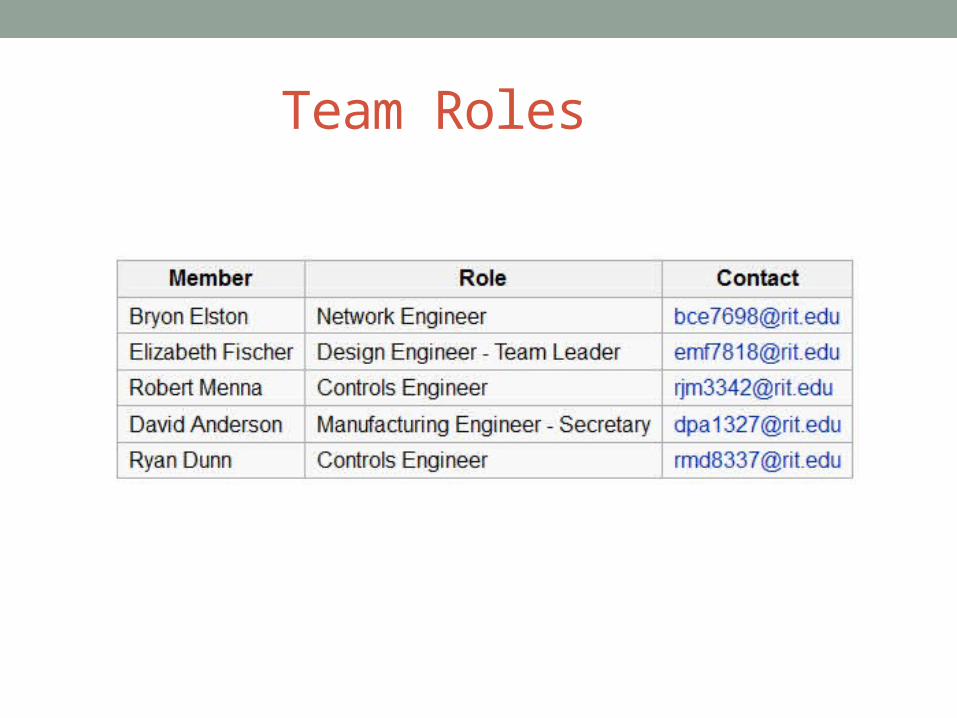
Team Roles

Project Objectives & Goals• Improve 13371 design
• Reduce Backlash• Increase Speed• Add Remote Access
• Increase access to nanotechnology

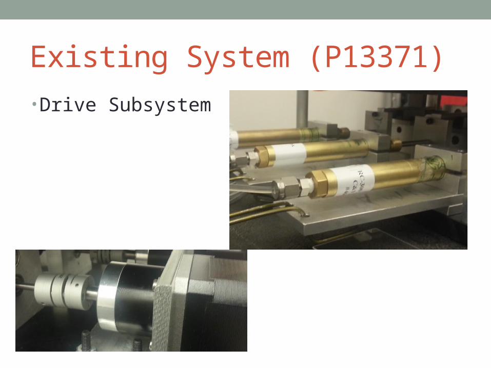
Existing System (P13371)

Existing System (P13371)
Existing System (P13371)
• Drive Subsystem

Drive Subsystem Continued
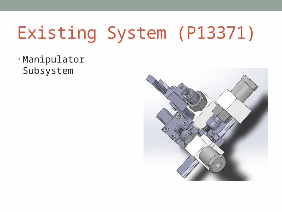
Existing System (P13371) • Manipulator Subsystem
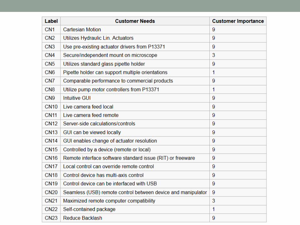

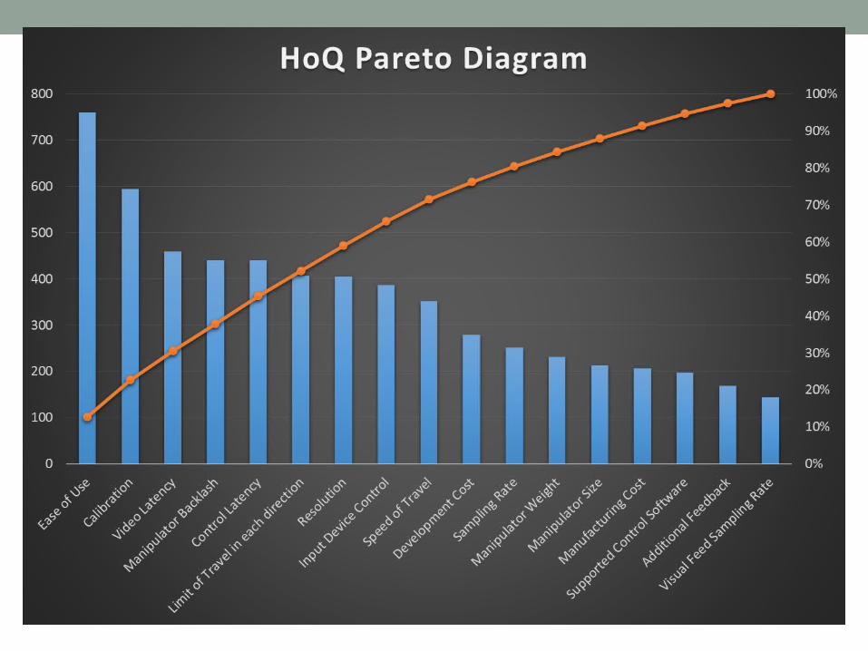

House of Quality Pareto Analysis• Top Specifications
• Ease of Use• Calibration• Video Latency• Manipulator Backlash• Control Latency• Limit of Travel in Each Direction• Resolution• Input Device Control (Remote and Local)• Speed of Travel
• If Top 9 of 17 Specs Met• 75% of customer needs satisfied

System Architecture

MECHANICAL SYSTEM

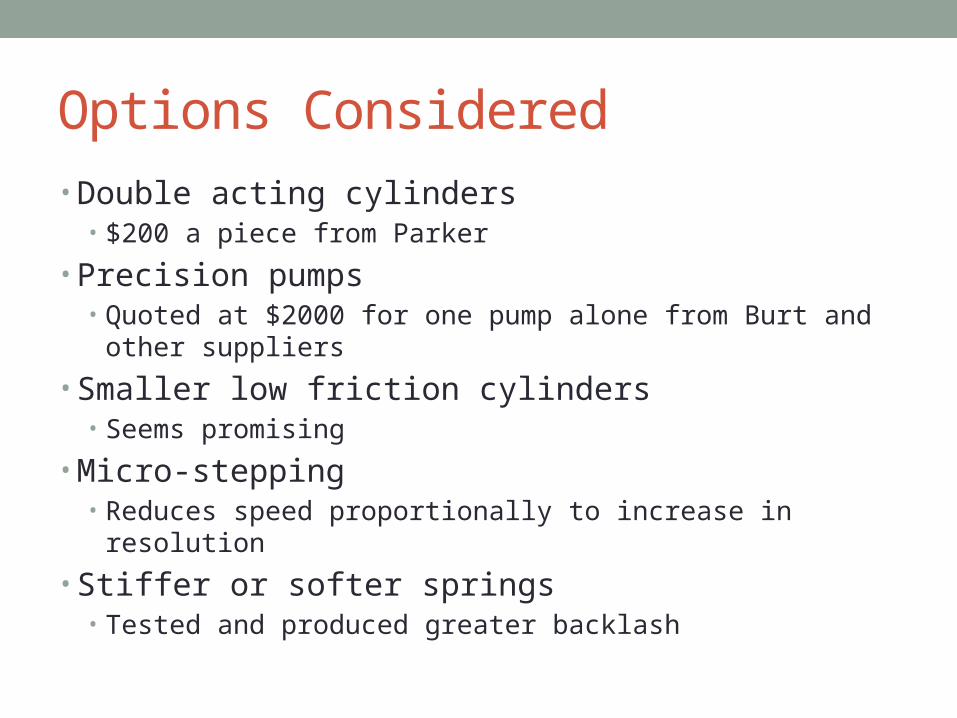
Options Considered• Double acting cylinders
• $200 a piece from Parker
• Precision pumps • Quoted at $2000 for one pump alone from Burt and other suppliers
• Smaller low friction cylinders• Seems promising
• Micro-stepping • Reduces speed proportionally to increase in resolution
• Stiffer or softer springs• Tested and produced greater backlash

Speed Improvement Pugh Matrix
Speed ImprovementA B C C
Gear Box MotorsSelection CriteriaOption will improve speed S S SOption cost + + -Complexity of installation S S -Complexity of integration - - +Likelihood to improve backlash - - +Sum + 's 1 1 1Sum 0's 2 2 2Sum -'s 2 2 2Totals -1 -1 0
Concepts
Manipulator Cylinders
New Lead Screw

Manipulator Cylinder Pugh Matrix
Piston Selection Concepts A B C D E Parker
Hydraulic
Control Line
(1110201)
Control Line
Midget
SMC (MQP10-
10S)Current SystemSelection Criteria
Stroke Length + S S S Smaller Bore - S - + Cost - S S - Contains Return Spring S S - - Reduces Friction + S S + Provides Precise Control + - S + Appropriate Pressure Range - + + + Sum + 's 3 1 1 4 Sum 0's 1 5 4 1 Sum -'s 3 1 2 2 Totals 0 0 -1 2
Most Important
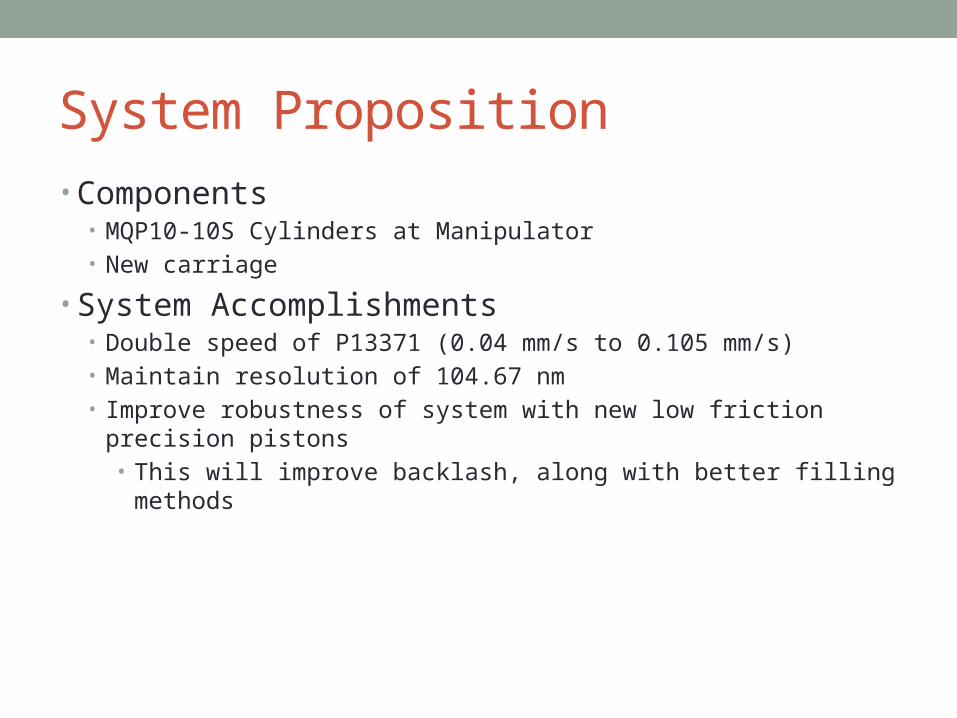
System Proposition • Components
• MQP10-10S Cylinders at Manipulator• New carriage
• System Accomplishments• Double speed of P13371 (0.04 mm/s to 0.105 mm/s)• Maintain resolution of 104.67 nm• Improve robustness of system with new low friction precision pistons
• This will improve backlash, along with better filling methods

SMC MQP10-10S Pistons
PUMP SUBSYSTEM

Stepper Motors

Stepper Motors
• Gear ratio: 13.76 planetary Gear
• Max holding torque: 7.55 N-m
• Max sustainable torque: 2.94 N-m
• Step angle: 0.067 degrees
• Max Speed: 22.88 RPM
• # Leads: 4 – Bipolar stepper
• Electrical: 12V supply 1.6A/phase

Stepper Motors

Assembly
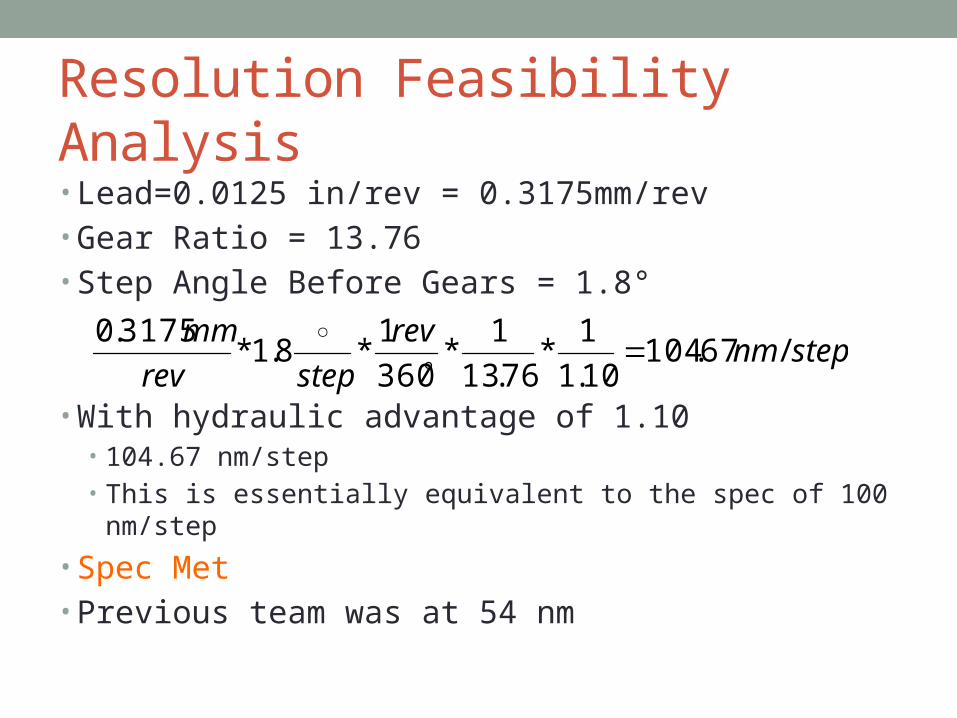
Resolution Feasibility Analysis• Lead=0.0125 in/rev = 0.3175mm/rev• Gear Ratio = 13.76• Step Angle Before Gears = 1.8°
• With hydraulic advantage of 1.10• 104.67 nm/step• This is essentially equivalent to the spec of 100 nm/step
• Spec Met• Previous team was at 54 nm
stepnmrev
steprev
mm/67.104
10.1
1*
76.13
1*
360
1*8.1*
3175.0

Range of Motion Feasibility Analysis• Change to Manipulator Cylinders only
• New Cylinders have a stroke of 10mm• Spec. is 0.25cm<x<1cm for each axis• 10mm=1cm
• If the equilibrium position is set to half stroke the range of motion in each direction is 0.5 cm
• Spec Met (FS=2)• Previous team was at 1.1 cm

Speed Feasibility Analysis• Motor Speed= 22rpm• Lead of Lead Screw= 0.3175 mm/rev
• Speed Spec= > 0.5 mm/s• 0.1056 mm/s < 0.5 mm/s
• Spec Not Met
• Previous team had a measured speed of 0.04 mm/s listed in technical report• Proposed solution provides twice the speed of previous

Spring Selectionmax spring distance 16.4 mm d1 16.4 inches 0.645minimum 6.4 mm d2 6.4 inches 0.252ID (mm) 0.093total compression (mm) 10 0.393
Spring 1 9657K296 $6.17 length in 1compression in 0.748k value 3.15Force lb 2.3562 10.45N
Spring 2 9657K81 $5.15 length in 0.937compression in 0.685k value 0.29Force lb 0.19865 0.885N
Spring 3 9657K46 $6.88 length in 1compression in 0.748k value 0.76Force lb 0.56848 2.53N
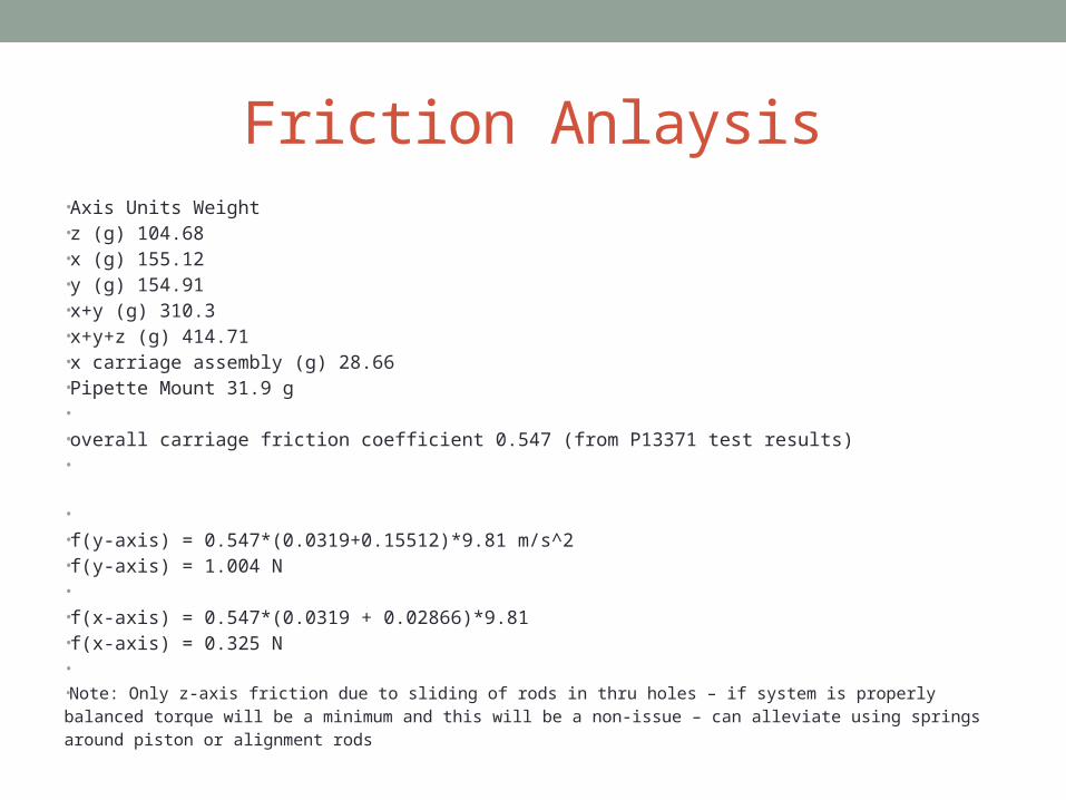
Friction Anlaysis•Axis Units Weight•z (g) 104.68•x (g) 155.12•y (g) 154.91•x+y (g) 310.3•x+y+z (g) 414.71•x carriage assembly (g) 28.66•Pipette Mount 31.9 g• •overall carriage friction coefficient 0.547 (from P13371 test results)•
• •f(y-axis) = 0.547*(0.0319+0.15512)*9.81 m/s^2•f(y-axis) = 1.004 N• •f(x-axis) = 0.547*(0.0319 + 0.02866)*9.81•f(x-axis) = 0.325 N• •Note: Only z-axis friction due to sliding of rods in thru holes – if system is properly balanced torque will be a minimum and this will be a non-issue – can alleviate using springs around piston or alignment rods
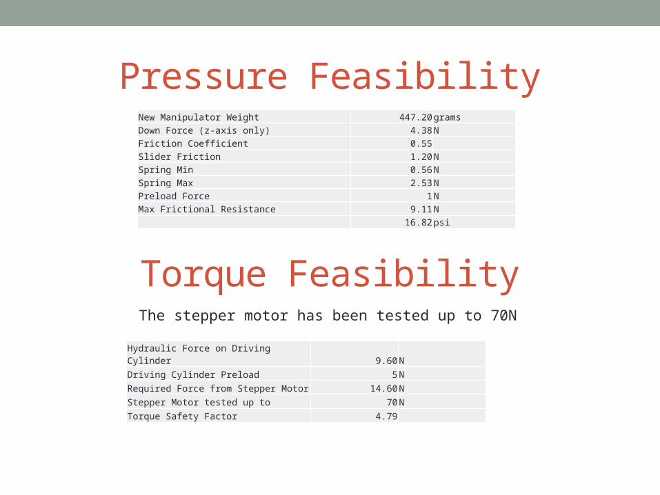
Pressure Feasibility
The stepper motor has been tested up to 70N
New Manipulator Weight 447.20 gramsDown Force (z-axis only) 4.38 NFriction Coefficient 0.55Slider Friction 1.20 NSpring Min 0.56 NSpring Max 2.53 NPreload Force 1 NMax Frictional Resistance 9.11 N
16.82psi
Torque Feasibility
Hydraulic Force on Driving Cylinder 9.60 N
Driving Cylinder Preload 5 N
Required Force from Stepper Motor 14.60N
Stepper Motor tested up to 70N
Torque Safety Factor 4.79
MANIPULATOR SUBSYSTEM

Manipulator Assembly

Manipulator Continued

Manipulator Continued

Manipulator Continued

Feasibility Analysis• Manipulator was modeled in Solidworks• Weight =447.2 g (Spec Met of 550 g)
• Previous team was at 689 g
• Size 11.86 x 11.93 x 10.01 cm
(Spec Not Met of 8 X 8 X 8 cm)• Previous Team was at 13 x 13 x 13

Full Mechanical System Assembly


ELECTRONIC SYSTEM

CONTROLS SUBSYSTEM

Control System Overview

Software Concept Selection
• Decision made to implement software via D3 – MATLAB with Java networking

MATLAB Local Model
• Accepts command and control signals from client (i.e. to direct manipulator)
• Interfaces with camera hardware for live video imaging access
• Image processing for automated calibration (needle tip located, centered)
• Manipulator resolution mapped to speed setting, configurable via software
• P13371 provides working Java serial communication to microcontroller Implementing USB interface

Remote Access Support
MATLAB local model wrapping underlying Java networking support
Command and Control Channel –• Accepts input from remote client to direct local model
Manipulator movement via client input devices Speed control
• Command protocol implemented via Transmission Control Protocol (TCP) Connection based, ordered, error-checked command transmission
Media Streaming Channel –• Captures image/video media from manipulator microscope camera• Media is streamed to connected client in real time• Client-configurable image quality (resolution, color depth, compression)• Media data transmitted via User Datagram Protocol (UDP)
• Connectionless, low overhead, reduced latency bulk data transmission

Remote Access Support
• Proof of concept MATLAB / Java software completed• Feasibility and reliability of software concept selection proven• Portable with simple, single executable and MATLAB runtime library• Research and development paves the way to refine final solution
Host (Local Model)Client (Remote Model)

Remote Access Support
Latency ConsiderationsThe one-way trip time between host and client.
• Video/image media streaming from host to client (one way)• Implemented via UDP for rapid, low overhead, bulk data transmission• Sacrifices ordering, error checking, protocol-level guarantee for real-time streaming
• It is okay to lose image frames rather than delaying entire application/experience
(stream may be smoothed)
• Command sending from client to host (round trip)• Implemented via TCP with request/reply loop:
1. Client sends command “Move to coordinate”
2. Host receives command, provides error-checking
3. Host sends acknowledgement to client informing command has been accepted
4. Client receives acknowledgement
• Optimal command latency: <= 200 ms
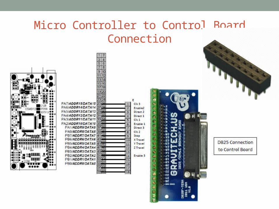
Micro Controller to Control Board Connection

3-Axis Control Board

3-Axis Control Board• Toshiba TB6560AHQ
• 1 – 1/16 micro stepping setting• 12 – 36 VDC power • Adjustable 0.5 – 2.5 A driver current / phase• PWM actuation output
• 3-axis of motion
• Limit switch functionality
• Parallel port connection
• Overload, over-current, over-temp protection

COMPLETE SYSTEM

Full System Test Plan• Cost
• Keep track of all expenses
• Weight• Weight of Manipulator (predicted 416 grams)
• Static Coefficient of Friction• Force required to move each axis measured with a spring scale
• Size• Measure the assembled manipulator
• Range of Motion• Measure the travel distance of the piston
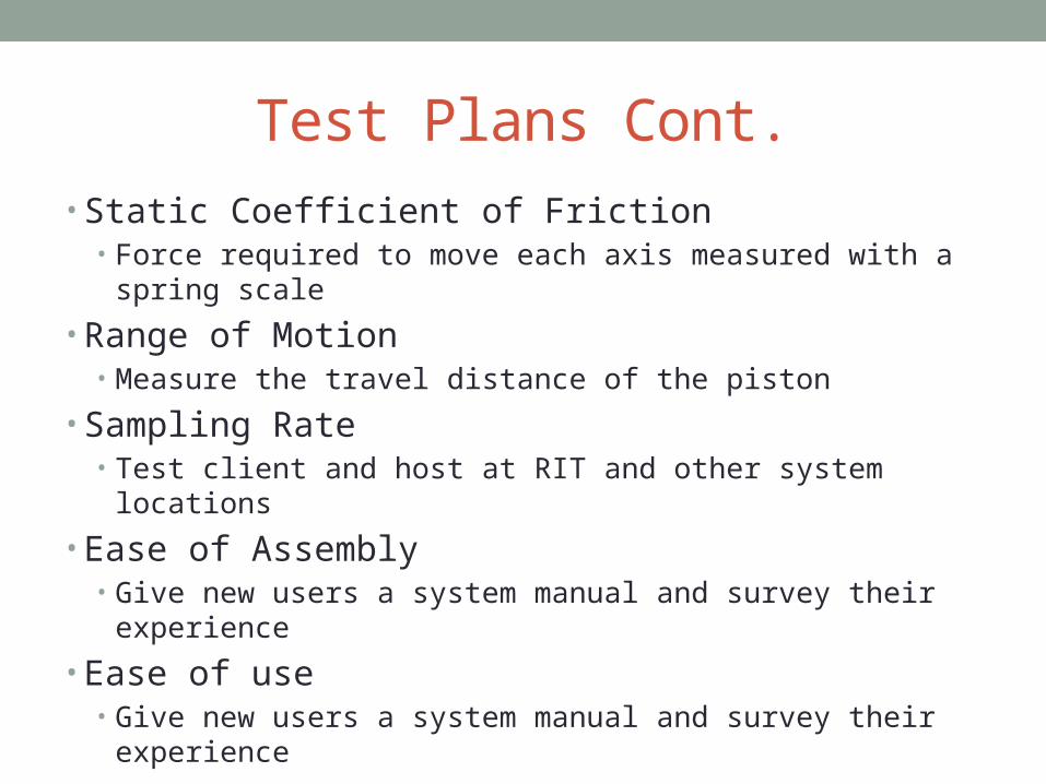
Test Plans Cont.• Static Coefficient of Friction
• Force required to move each axis measured with a spring scale
• Range of Motion• Measure the travel distance of the piston
• Sampling Rate• Test client and host at RIT and other system locations
• Ease of Assembly• Give new users a system manual and survey their experience
• Ease of use• Give new users a system manual and survey their experience

Test Plans Cont.• Resolution
• Measure distance traveled after 20 revolutions of the stepper motor and compare to theoretical
• Speed of travel• Measure the time taken to move the manipulator to its full range of
motion• Time system run at max speed for 10 revs and see distance
traveled
• System backlash• Number of revolutions needed to change direction
• Safe in full range of motion• Make sure nothing is damaged while testing limits of travel
# Specification (metric)Unit of
MeasureTarget Value
TheoreticalValue
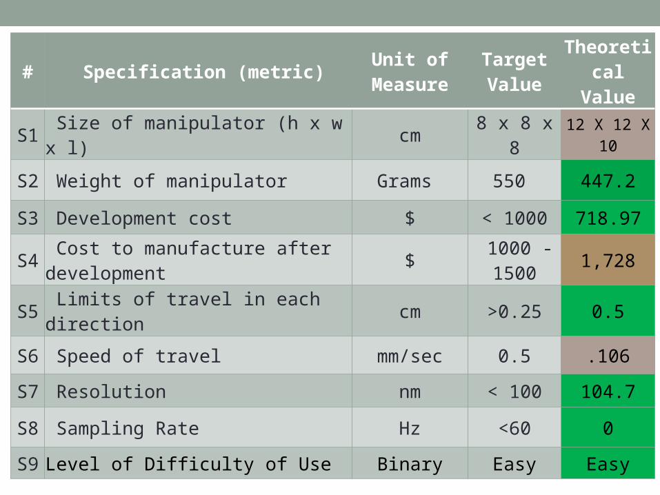
S1 Size of manipulator (h x w x l) cm 8 x 8 x 8 12 X 12 X 10
S2 Weight of manipulator Grams 550 447.2
S3 Development cost $ < 1000 718.97
S4 Cost to manufacture after development $
1000 -1500 1,728
S5 Limits of travel in each direction cm >0.25 0.5
S6 Speed of travel mm/sec 0.5 .106
S7 Resolution nm < 100 104.7
S8 Sampling Rate Hz <60 0
S9 Level of Difficulty of Use Binary Easy Easy

# Specification (metric)Unit of
MeasureTarget Value
Theoretical Value
S10 Supported Control Software Binary Yes Yes
S11 Visual Feed Sampling Rate Hz <60 Yes
S12 System is Controlled by a Device (Remotely and Locally)
Binary Yes Yes
S13 System Provides Additional Feedback Subjective Yes Yes
S14 System Provides Calibration Binary Yes Yes
S15 System Backlash Revolutions <3 0
S16 Video LatencyFrames Per
Second 30 30
S17 Control Latency ms <200 200

Project Cost• Cost of suggested improvements (Development Cost): ~$720
• New Piston Cylinders• New Manipulator Carriage • Springs• Preious team was at $2,128
• Estimated Manufacturing Cost: ~$1,728• Previous team was at $1,471
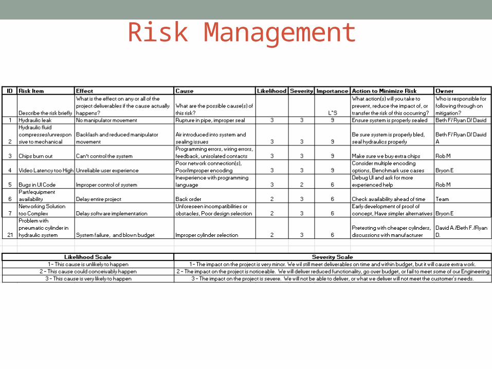
Risk Management


Project Planning• MSD I
• Week 11• Get MSD II project green light• Review BOM & Prepare Order Forms for long lead items to place over the
summer
• MSD II• Week 1
• Obtain All parts• Re-familiarize ourselves with the project• Begin Remote access programming
• Week 3• Mechanical Manufacturing is complete• Assembly has been begun• Networking Programing first draft is complete

Project Planning • MSD II (cont.)
• Week 5 • System Prototype assembled, and met with guide and customer
• Week 8• System completely assembled and ready to begin testing
• Week 12• Testing is Completed
• Week 14• Final Presentation• User manual is complete• Tech. paper is complete• Poster is complete

Acknowledgments• Mr. Wellin -RIT ME Department
• Dr. Schrlau –RIT ME Department
• Nick Hensel – RIT ME Department
• Bridget Lally – RIT EE Department
• Sakif Noor – RIT ME Department
• Team P13371

Questions?