hydraulic power unit 5hp/8gpm/20gal - cmfmfg.com user manual.pdf · hydraulic power unit...
TRANSCRIPT
Hydraulic Power Unit 5HP/8GPM/20GAL
REV0.0 1
Table of Contents
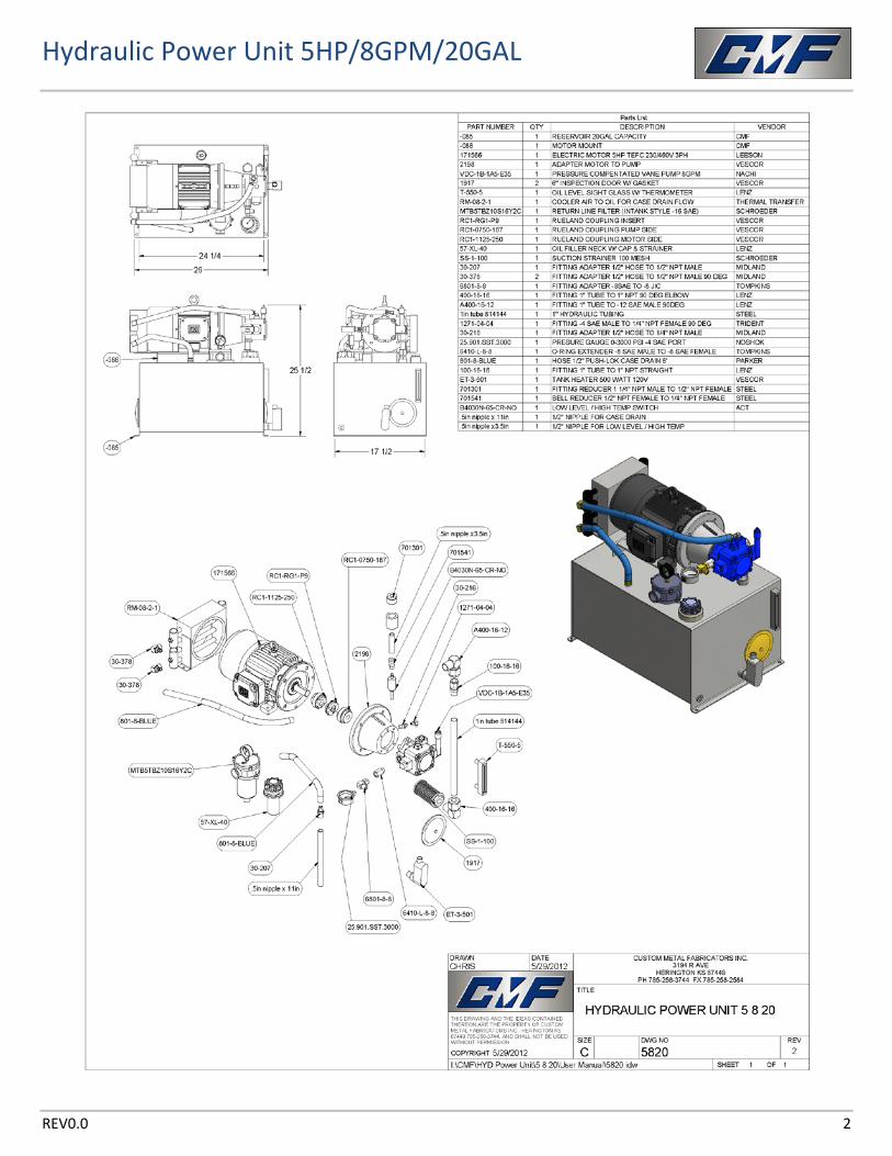
Assembly Drawing ........................................................... 2 Maintenance & Startup ................................................... 3 Troubleshooting .............................................................. 8 Spec Sheets .................................................................... 23
Hydraulic Power Unit 5HP/8GPM/20GAL
REV0.0 2
Hydraulic Power Unit 5HP/8GPM/20GAL
REV0.0 3
GENERAL HYDRAULIC POWER UNIT MAINTENANCE AND START UP
GUIDELINES
POWER UNIT START-UP INFORMATION
1. While in transit or during installation, a power unit may be subjected to many unusual conditions. On systems with separately mounted pumps and motors, the alignment between shafts should be checked with an indicator or straight edge and adjustments made if necessary. Pump misalignment drastically reduces pump bearing life. Check setscrews in couplings for loosening. Tighten as required.
2. Fill the reservoir with filtered fluid as recommended by pump manufacturer (see pump date), usually, a premium grade hydraulic fluid with a viscosity index of 90 or higher. For machine tool feed, and similar applications at pressure to 600 PSI and temperatures to 130 degrees F, a fluid viscosity of 150 SSU at 100 degrees F is permissible. For higher pressures and temperatures, a fluid viscosity from 225 to 325 SSU at 100 degrees F will provide maximum pump service life. For cold startup applications at temperatures down to 0 degrees F, Automatic Transmission Fluid, DEXRON TYPE D2, will usually prove satisfactory.
3. Connect the motor to the proper electrical source, checking the motor name plate for proper wiring of dual voltage motors. Jog the motor to check rotation. Poly-phase motors are bi-directional and proper rotation might be established by reversing any two power leads. Consult a qualified electrician.
4. Pump noise and “crackle” is most often caused by air entering the pump section. The tightening of suction fittings will usually eliminate such problems. If pump fails to prime, vent discharge pipe to atmosphere to establish fluid flow.
5. IMPORTANT! After power unit has been started and all the lines filled, replenish the oil in the reservoir to the proper level. The fluid level should be maintained so it always shows in the sight gauge. This is of utmost importance when an immersion type heat exchanger is used to prevent condensation from collecting on uncovered cooling coils.
6. System pressures should be set as low as possible to prevent unnecessary fluid heating; on some applications, this setting may be from 50 to 200 PSI above necessary static pressures to overcome dynamic pressure drop or to achieve proper acceleration.
7. For most industrial applications, an operating temperature of 150 degrees F is considered maximum. At higher temperatures, difficulty is often experienced in maintaining reliable and consistent hydraulic control, component service life is reduced, hydraulic fluid deteriorates, and a potential danger to operating personnel is created.
8. After the first few hours of operation, clean or install new elements in all filters to remove contamination from initial flushing of system plumbing.
9. If filters are equipped with bypass do not allow the filter to go into bypass. Change the element before bypass.
Hydraulic Power Unit 5HP/8GPM/20GAL
REV0.0 4
MAINTENANCE INSTRUCTIONS
Hydraulic systems are precision units and their continued smooth operation depends on proper care. Therefore, do not neglect your hydraulic systems. Keep them clean, change the oil and oil filter at established intervals, and follow prescribed maintenance.
Periodic procedures are as follows:
1. Check the reservoir oil level and add filtered oil as required. The level must be maintained between the high and low marked on the sight gauge.
2. Check the operating temperature and oil pressure. For most industrial applications, an operating temperature of 150 degrees F is considered maximum.
3. If an external suction filter is used, check filter indicator for dirty element at least every two hours for first eight hours of operating and clean when necessary. Check at least once every day for the next five days of operation and clean when necessary. Check periodically after that at intervals that will prevent the filter from bypassing or cavitating pump.
4. Check return filters as in step 3. These are usually finer filters, however, and will require more frequent element changes or cleansings than the suction filter. Always change filters when the oil is changed.
5. At least once a year or every 4,000 operating hours, the reservoir, pump suction filter (if one is used) and air vent filter should be cleaned; at this time check the entire system for possible future difficulties. Some applications or environmental conditions may dictate such maintenance be performed at more frequent intervals.
6. Periodically make visual checks of all hose and tube connections. Regular checking and tightening of all hydraulic connections will help to assure trouble-free operation.
7. Periodically check pressure setting. The system was designed to operate at a specific pressure and increasing the pressure above that will result in motor overload. The system should be operated at the minimum pressure to do the intended function, as the lower the system pressure, the longer will be the pump life.
8. Check pump/motor coupling periodically for misalignment. A flexible coupling should always be used and shafts accurately aligned parallel and angularly. Check setscrews in couplings for loosening. Tighten as required.
9. The reservoir cover should remain tightly sealed at all times, except in case of in-tank maintenance and periodic checks for in-tank leaks, in order to prevent atmospheric contamination from entering the system.
Hydraulic Power Unit 5HP/8GPM/20GAL
REV0.0 5
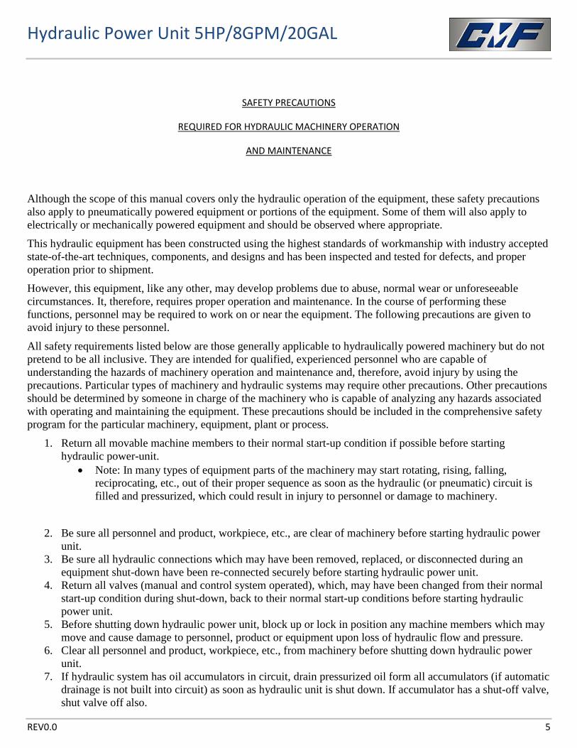
SAFETY PRECAUTIONS
REQUIRED FOR HYDRAULIC MACHINERY OPERATION
AND MAINTENANCE
Although the scope of this manual covers only the hydraulic operation of the equipment, these safety precautions also apply to pneumatically powered equipment or portions of the equipment. Some of them will also apply to electrically or mechanically powered equipment and should be observed where appropriate.
This hydraulic equipment has been constructed using the highest standards of workmanship with industry accepted state-of-the-art techniques, components, and designs and has been inspected and tested for defects, and proper operation prior to shipment.
However, this equipment, like any other, may develop problems due to abuse, normal wear or unforeseeable circumstances. It, therefore, requires proper operation and maintenance. In the course of performing these functions, personnel may be required to work on or near the equipment. The following precautions are given to avoid injury to these personnel.
All safety requirements listed below are those generally applicable to hydraulically powered machinery but do not pretend to be all inclusive. They are intended for qualified, experienced personnel who are capable of understanding the hazards of machinery operation and maintenance and, therefore, avoid injury by using the precautions. Particular types of machinery and hydraulic systems may require other precautions. Other precautions should be determined by someone in charge of the machinery who is capable of analyzing any hazards associated with operating and maintaining the equipment. These precautions should be included in the comprehensive safety program for the particular machinery, equipment, plant or process.
1. Return all movable machine members to their normal start-up condition if possible before starting hydraulic power-unit.
• Note: In many types of equipment parts of the machinery may start rotating, rising, falling, reciprocating, etc., out of their proper sequence as soon as the hydraulic (or pneumatic) circuit is filled and pressurized, which could result in injury to personnel or damage to machinery.
2. Be sure all personnel and product, workpiece, etc., are clear of machinery before starting hydraulic power unit.
3. Be sure all hydraulic connections which may have been removed, replaced, or disconnected during an equipment shut-down have been re-connected securely before starting hydraulic power unit.
4. Return all valves (manual and control system operated), which, may have been changed from their normal start-up condition during shut-down, back to their normal start-up conditions before starting hydraulic power unit.
5. Before shutting down hydraulic power unit, block up or lock in position any machine members which may move and cause damage to personnel, product or equipment upon loss of hydraulic flow and pressure.
6. Clear all personnel and product, workpiece, etc., from machinery before shutting down hydraulic power unit.
7. If hydraulic system has oil accumulators in circuit, drain pressurized oil form all accumulators (if automatic drainage is not built into circuit) as soon as hydraulic unit is shut down. If accumulator has a shut-off valve, shut valve off also.
Hydraulic Power Unit 5HP/8GPM/20GAL
REV0.0 6
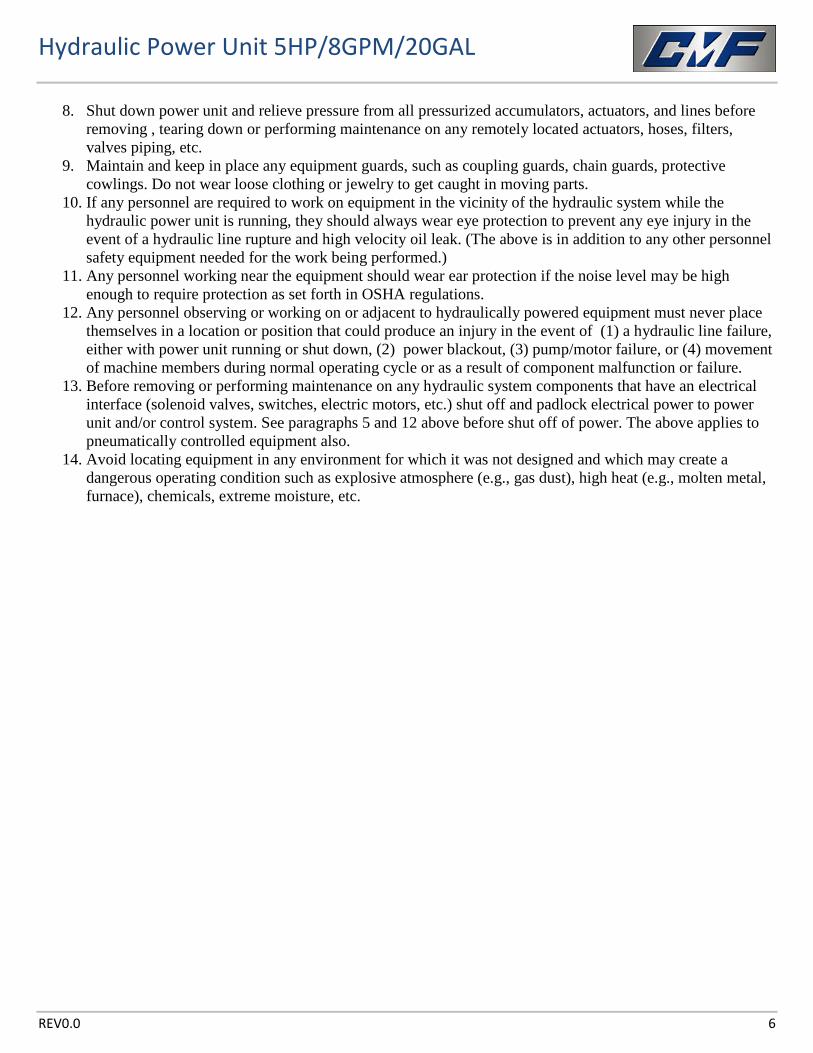
8. Shut down power unit and relieve pressure from all pressurized accumulators, actuators, and lines before removing , tearing down or performing maintenance on any remotely located actuators, hoses, filters, valves piping, etc.
9. Maintain and keep in place any equipment guards, such as coupling guards, chain guards, protective cowlings. Do not wear loose clothing or jewelry to get caught in moving parts.
10. If any personnel are required to work on equipment in the vicinity of the hydraulic system while the hydraulic power unit is running, they should always wear eye protection to prevent any eye injury in the event of a hydraulic line rupture and high velocity oil leak. (The above is in addition to any other personnel safety equipment needed for the work being performed.)
11. Any personnel working near the equipment should wear ear protection if the noise level may be high enough to require protection as set forth in OSHA regulations.
12. Any personnel observing or working on or adjacent to hydraulically powered equipment must never place themselves in a location or position that could produce an injury in the event of (1) a hydraulic line failure, either with power unit running or shut down, (2) power blackout, (3) pump/motor failure, or (4) movement of machine members during normal operating cycle or as a result of component malfunction or failure.
13. Before removing or performing maintenance on any hydraulic system components that have an electrical interface (solenoid valves, switches, electric motors, etc.) shut off and padlock electrical power to power unit and/or control system. See paragraphs 5 and 12 above before shut off of power. The above applies to pneumatically controlled equipment also.
14. Avoid locating equipment in any environment for which it was not designed and which may create a dangerous operating condition such as explosive atmosphere (e.g., gas dust), high heat (e.g., molten metal, furnace), chemicals, extreme moisture, etc.
Hydraulic Power Unit 5HP/8GPM/20GAL
REV0.0 7
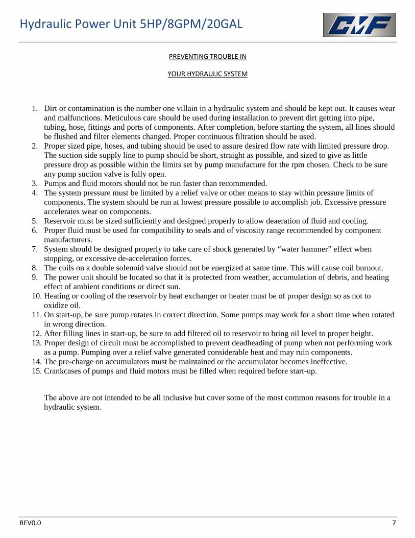
PREVENTING TROUBLE IN
YOUR HYDRAULIC SYSTEM
1. Dirt or contamination is the number one villain in a hydraulic system and should be kept out. It causes wear and malfunctions. Meticulous care should be used during installation to prevent dirt getting into pipe, tubing, hose, fittings and ports of components. After completion, before starting the system, all lines should be flushed and filter elements changed. Proper continuous filtration should be used.
2. Proper sized pipe, hoses, and tubing should be used to assure desired flow rate with limited pressure drop. The suction side supply line to pump should be short, straight as possible, and sized to give as little pressure drop as possible within the limits set by pump manufacture for the rpm chosen. Check to be sure any pump suction valve is fully open.
3. Pumps and fluid motors should not be run faster than recommended. 4. The system pressure must be limited by a relief valve or other means to stay within pressure limits of
components. The system should be run at lowest pressure possible to accomplish job. Excessive pressure accelerates wear on components.
5. Reservoir must be sized sufficiently and designed properly to allow deaeration of fluid and cooling. 6. Proper fluid must be used for compatibility to seals and of viscosity range recommended by component
manufacturers. 7. System should be designed properly to take care of shock generated by “water hammer” effect when
stopping, or excessive de-acceleration forces. 8. The coils on a double solenoid valve should not be energized at same time. This will cause coil burnout. 9. The power unit should be located so that it is protected from weather, accumulation of debris, and heating
effect of ambient conditions or direct sun. 10. Heating or cooling of the reservoir by heat exchanger or heater must be of proper design so as not to
oxidize oil. 11. On start-up, be sure pump rotates in correct direction. Some pumps may work for a short time when rotated
in wrong direction. 12. After filling lines in start-up, be sure to add filtered oil to reservoir to bring oil level to proper height. 13. Proper design of circuit must be accomplished to prevent deadheading of pump when not performing work
as a pump. Pumping over a relief valve generated considerable heat and may ruin components. 14. The pre-charge on accumulators must be maintained or the accumulator becomes ineffective. 15. Crankcases of pumps and fluid motors must be filled when required before start-up.
The above are not intended to be all inclusive but cover some of the most common reasons for trouble in a hydraulic system.
Hydraulic Power Unit 5HP/8GPM/20GAL
REV0.0 8
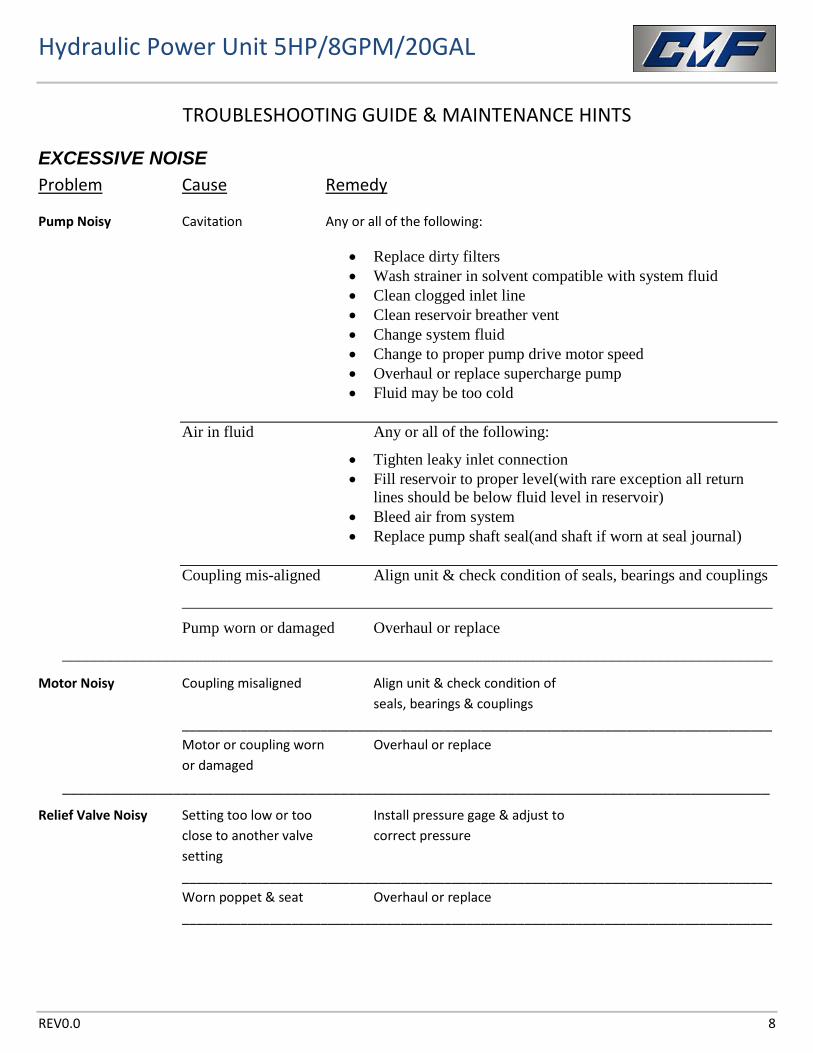
TROUBLESHOOTING GUIDE & MAINTENANCE HINTS
EXCESSIVE NOISE Problem Cause Remedy
Pump Noisy Cavitation Any or all of the following:
• Replace dirty filters • Wash strainer in solvent compatible with system fluid • Clean clogged inlet line • Clean reservoir breather vent • Change system fluid • Change to proper pump drive motor speed • Overhaul or replace supercharge pump • Fluid may be too cold
Air in fluid Any or all of the following:
• Tighten leaky inlet connection • Fill reservoir to proper level(with rare exception all return
lines should be below fluid level in reservoir) • Bleed air from system • Replace pump shaft seal(and shaft if worn at seal journal)
Coupling mis-aligned Align unit & check condition of seals, bearings and couplings
__________________________________________________________________________
Pump worn or damaged Overhaul or replace
_________________________________________________________________________________________
Motor Noisy Coupling misaligned Align unit & check condition of seals, bearings & couplings _________________________________________________________________________________ Motor or coupling worn Overhaul or replace or damaged
_________________________________________________________________________________________
Relief Valve Noisy Setting too low or too Install pressure gage & adjust to close to another valve correct pressure setting _________________________________________________________________________________ Worn poppet & seat Overhaul or replace
_________________________________________________________________________________
Hydraulic Power Unit 5HP/8GPM/20GAL
REV0.0 9
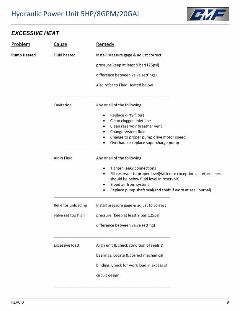
EXCESSIVE HEAT
Problem Cause Remedy
Pump Heated Fluid heated Install pressure gage & adjust correct
pressure(keep at least 9 bar(125psi)
difference between valve settings).
Also refer to Fluid Heated below.
______________________________________________________
Cavitation Any or all of the following:
• Replace dirty filters • Clean clogged inlet line • Clean reservoir breather vent • Change system fluid • Change to proper pump drive motor speed • Overhaul or replace supercharge pump
______________________________________________________
Air in Fluid Any or all of the following:
• Tighten leaky connections • Fill reservoir to proper level(with rare exception all return lines
should be below fluid level in reservoir) • Bleed air from system • Replace pump shaft seal(and shaft if worn at seal journal)
______________________________________________________
Relief or unloading Install pressure gage & adjust to correct
valve set too high pressure.(Keep at least 9 bar(125psi)
difference between valve setting)
______________________________________________________
Excessive load Align unit & check condition of seals &
bearings. Locate & correct mechanical
binding. Check for work load in excess of
circuit design.
______________________________________________________
Hydraulic Power Unit 5HP/8GPM/20GAL
REV0.0 10
______________________________________________________
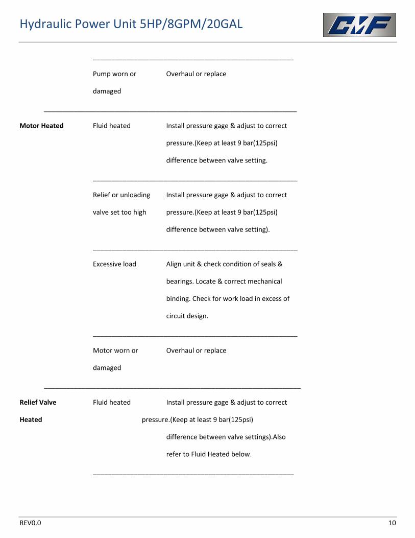
Pump worn or Overhaul or replace
damaged
____________________________________________________________________
Motor Heated Fluid heated Install pressure gage & adjust to correct
pressure.(Keep at least 9 bar(125psi)
difference between valve setting.
_______________________________________________________
Relief or unloading Install pressure gage & adjust to correct
valve set too high pressure.(Keep at least 9 bar(125psi)
difference between valve setting).
_______________________________________________________
Excessive load Align unit & check condition of seals &
bearings. Locate & correct mechanical
binding. Check for work load in excess of
circuit design.
_______________________________________________________
Motor worn or Overhaul or replace
damaged
_____________________________________________________________________
Relief Valve Fluid heated Install pressure gage & adjust to correct
Heated pressure.(Keep at least 9 bar(125psi)
difference between valve settings).Also
refer to Fluid Heated below.
______________________________________________________
Hydraulic Power Unit 5HP/8GPM/20GAL
REV0.0 11
______________________________________________________
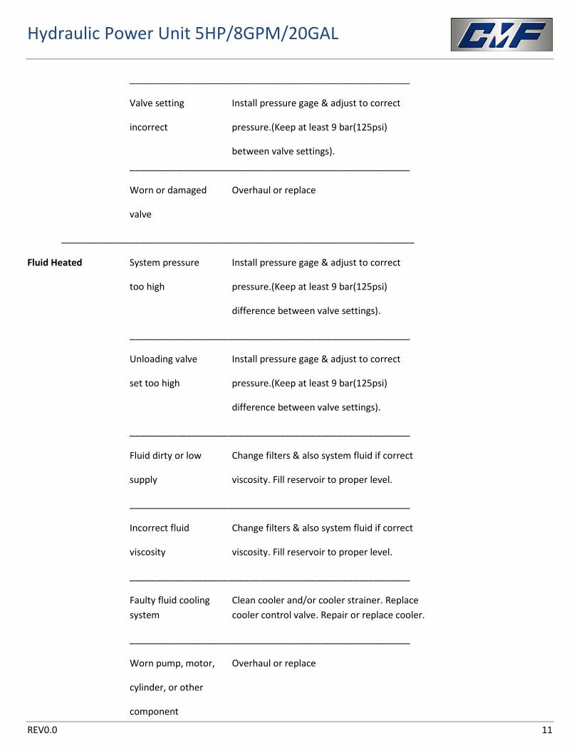
Valve setting Install pressure gage & adjust to correct
incorrect pressure.(Keep at least 9 bar(125psi)
between valve settings). ______________________________________________________
Worn or damaged Overhaul or replace
valve
____________________________________________________________________
Fluid Heated System pressure Install pressure gage & adjust to correct
too high pressure.(Keep at least 9 bar(125psi)
difference between valve settings).
______________________________________________________
Unloading valve Install pressure gage & adjust to correct
set too high pressure.(Keep at least 9 bar(125psi)
difference between valve settings).
______________________________________________________
Fluid dirty or low Change filters & also system fluid if correct
supply viscosity. Fill reservoir to proper level.
______________________________________________________
Incorrect fluid Change filters & also system fluid if correct
viscosity viscosity. Fill reservoir to proper level.
______________________________________________________
Faulty fluid cooling Clean cooler and/or cooler strainer. Replace system cooler control valve. Repair or replace cooler.
______________________________________________________
Worn pump, motor, Overhaul or replace
cylinder, or other
component
Hydraulic Power Unit 5HP/8GPM/20GAL
REV0.0 12
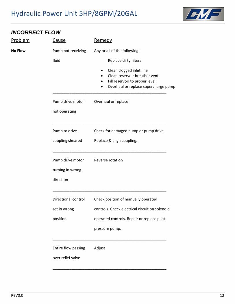
INCORRECT FLOW Problem Cause Remedy
No Flow Pump not receiving Any or all of the following:
fluid Replace dirty filters
• Clean clogged inlet line • Clean reservoir breather vent • Fill reservoir to proper level • Overhaul or replace supercharge pump
______________________________________________________
Pump drive motor Overhaul or replace
not operating
______________________________________________________
Pump to drive Check for damaged pump or pump drive.
coupling sheared Replace & align coupling.
______________________________________________________
Pump drive motor Reverse rotation
turning in wrong
direction
______________________________________________________
Directional control Check position of manually operated
set in wrong controls. Check electrical circuit on solenoid
position operated controls. Repair or replace pilot
pressure pump.
______________________________________________________
Entire flow passing Adjust
over relief valve
______________________________________________________
Hydraulic Power Unit 5HP/8GPM/20GAL
REV0.0 13
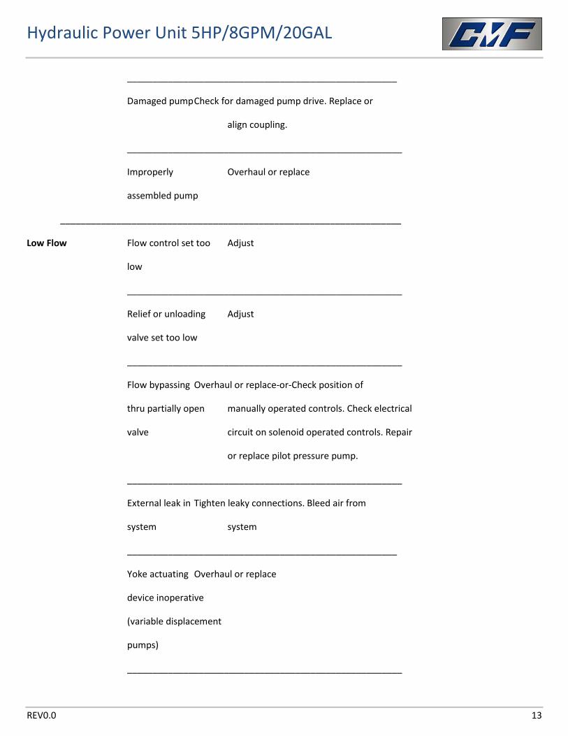
_____________________________________________________
Damaged pump Check for damaged pump drive. Replace or
align coupling.
______________________________________________________
Improperly Overhaul or replace
assembled pump
___________________________________________________________________
Low Flow Flow control set too Adjust
low
______________________________________________________
Relief or unloading Adjust
valve set too low
______________________________________________________
Flow bypassing Overhaul or replace-or-Check position of
thru partially open manually operated controls. Check electrical
valve circuit on solenoid operated controls. Repair
or replace pilot pressure pump.
______________________________________________________
External leak in Tighten leaky connections. Bleed air from
system system
_____________________________________________________
Yoke actuating Overhaul or replace
device inoperative
(variable displacement
pumps)
______________________________________________________
Hydraulic Power Unit 5HP/8GPM/20GAL
REV0.0 14
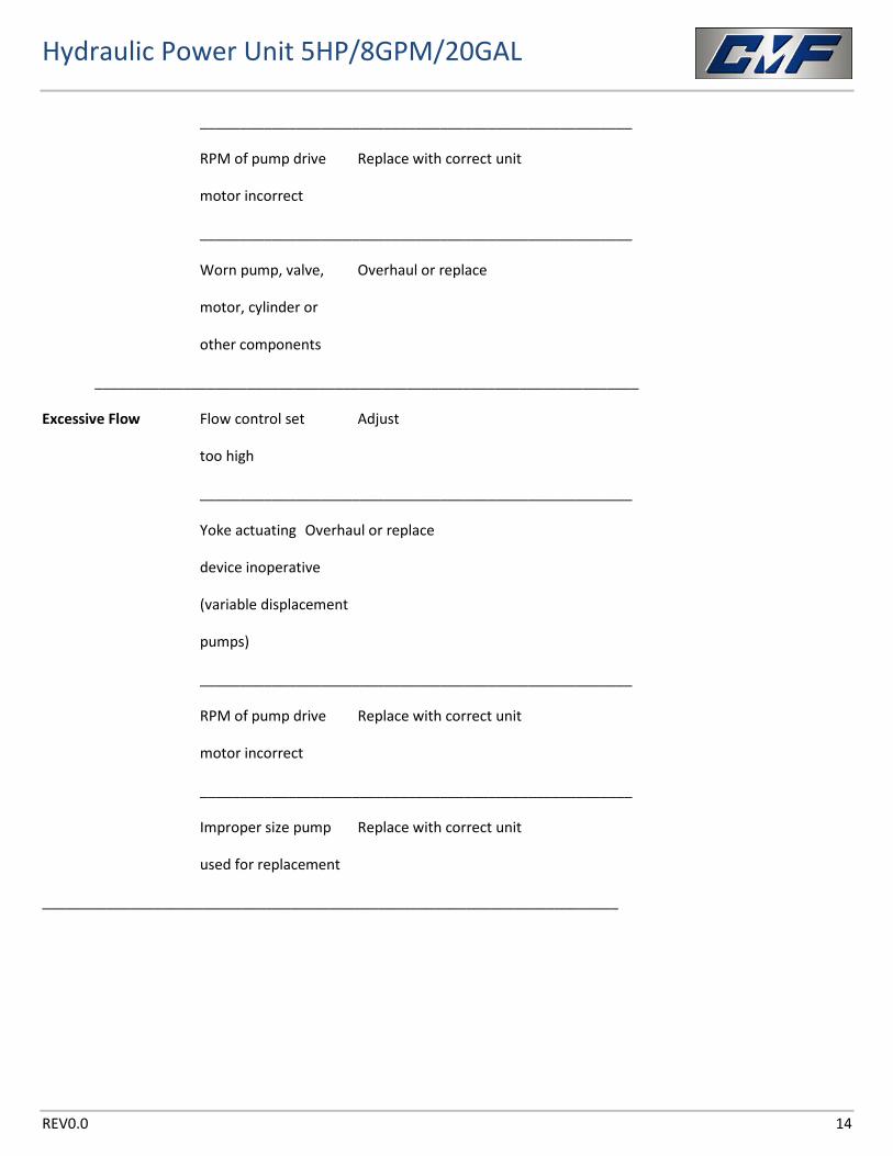
______________________________________________________
RPM of pump drive Replace with correct unit
motor incorrect
______________________________________________________
Worn pump, valve, Overhaul or replace
motor, cylinder or
other components
____________________________________________________________________
Excessive Flow Flow control set Adjust
too high
______________________________________________________
Yoke actuating Overhaul or replace
device inoperative
(variable displacement
pumps)
______________________________________________________
RPM of pump drive Replace with correct unit
motor incorrect
______________________________________________________
Improper size pump Replace with correct unit
used for replacement
________________________________________________________________________
Hydraulic Power Unit 5HP/8GPM/20GAL
REV0.0 15
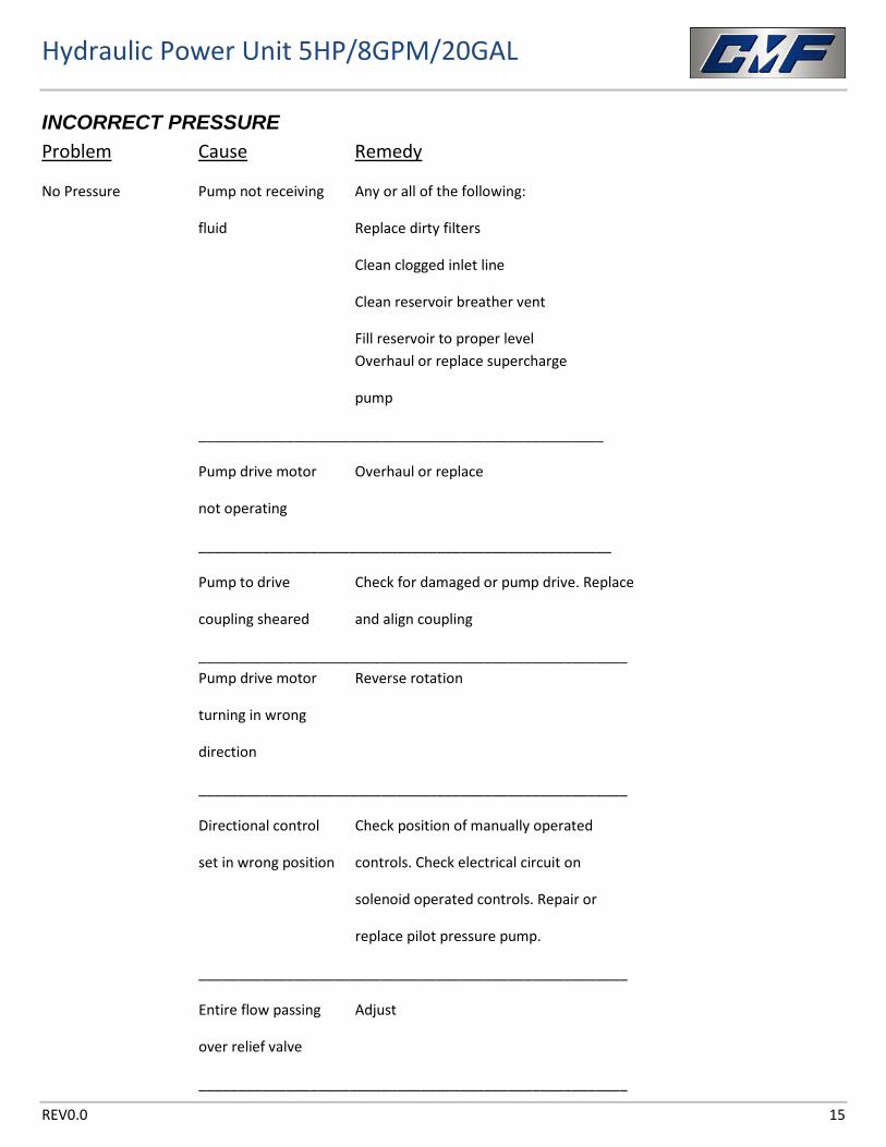
INCORRECT PRESSURE Problem Cause Remedy
No Pressure Pump not receiving Any or all of the following:
fluid Replace dirty filters
Clean clogged inlet line
Clean reservoir breather vent
Fill reservoir to proper level Overhaul or replace supercharge
pump
___________________________________________________
Pump drive motor Overhaul or replace
not operating
____________________________________________________
Pump to drive Check for damaged or pump drive. Replace
coupling sheared and align coupling
______________________________________________________ Pump drive motor Reverse rotation
turning in wrong
direction
______________________________________________________
Directional control Check position of manually operated
set in wrong position controls. Check electrical circuit on
solenoid operated controls. Repair or
replace pilot pressure pump.
______________________________________________________
Entire flow passing Adjust
over relief valve
______________________________________________________
Hydraulic Power Unit 5HP/8GPM/20GAL
REV0.0 16
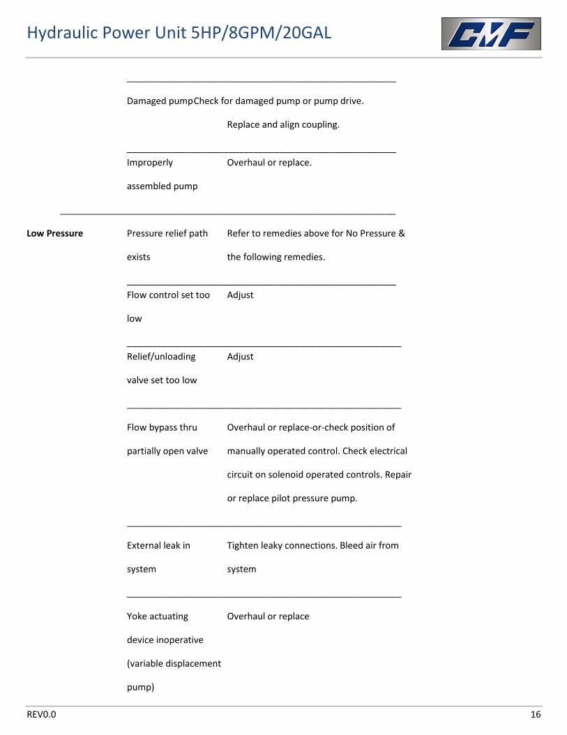
_____________________________________________________
Damaged pump Check for damaged pump or pump drive.
Replace and align coupling.
_____________________________________________________ Improperly Overhaul or replace.
assembled pump
__________________________________________________________________
Low Pressure Pressure relief path Refer to remedies above for No Pressure &
exists the following remedies.
_____________________________________________________ Flow control set too Adjust
low
______________________________________________________ Relief/unloading Adjust
valve set too low
______________________________________________________
Flow bypass thru Overhaul or replace-or-check position of
partially open valve manually operated control. Check electrical
circuit on solenoid operated controls. Repair
or replace pilot pressure pump.
______________________________________________________
External leak in Tighten leaky connections. Bleed air from
system system
______________________________________________________
Yoke actuating Overhaul or replace
device inoperative
(variable displacement
pump)
Hydraulic Power Unit 5HP/8GPM/20GAL
REV0.0 17
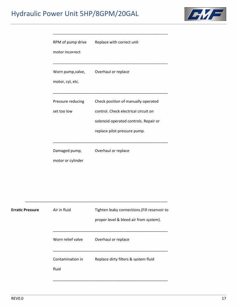
______________________________________________________
RPM of pump drive Replace with correct unit
motor incorrect
______________________________________________________
Worn pump,valve, Overhaul or replace
motor, cyl, etc.
______________________________________________________
Pressure reducing Check position of manually operated
set too low control. Check electrical circuit on
solenoid operated controls. Repair or
replace pilot pressure pump.
______________________________________________________
Damaged pump, Overhaul or replace
motor or cylinder
___________________________________________________________________
Erratic Pressure Air in fluid Tighten leaky connections.(Fill reservoir to
proper level & bleed air from system).
______________________________________________________
Worn relief valve Overhaul or replace
______________________________________________________
Contamination in Replace dirty filters & system fluid
fluid
______________________________________________________
Hydraulic Power Unit 5HP/8GPM/20GAL
REV0.0 18
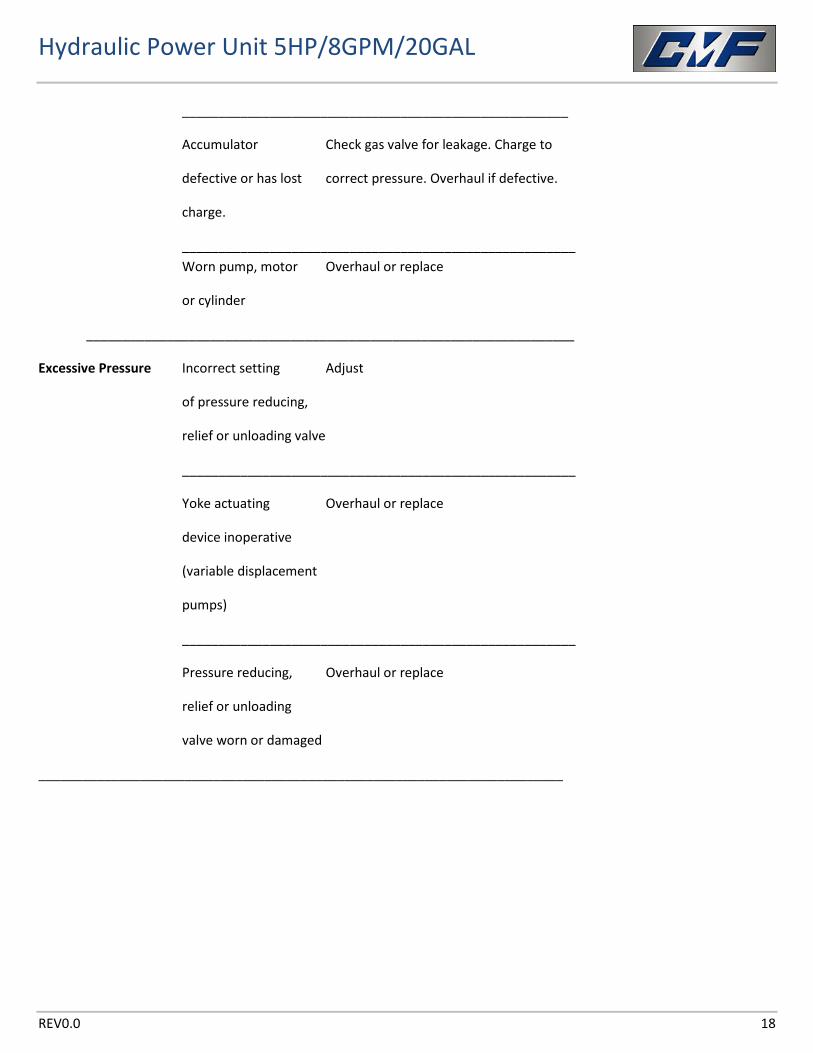
_____________________________________________________
Accumulator Check gas valve for leakage. Charge to
defective or has lost correct pressure. Overhaul if defective.
charge.
______________________________________________________ Worn pump, motor Overhaul or replace
or cylinder
___________________________________________________________________
Excessive Pressure Incorrect setting Adjust
of pressure reducing,
relief or unloading valve
______________________________________________________
Yoke actuating Overhaul or replace
device inoperative
(variable displacement
pumps)
______________________________________________________
Pressure reducing, Overhaul or replace
relief or unloading
valve worn or damaged
________________________________________________________________________
Hydraulic Power Unit 5HP/8GPM/20GAL
REV0.0 19
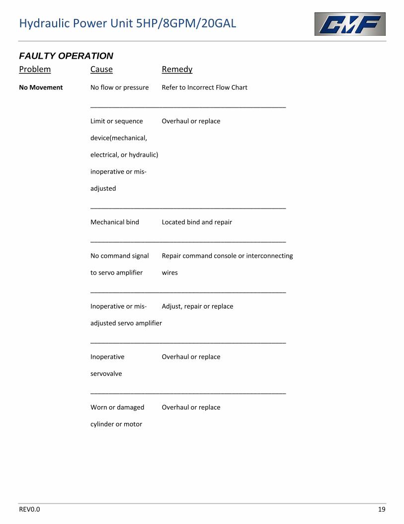
FAULTY OPERATION Problem Cause Remedy
No Movement No flow or pressure Refer to Incorrect Flow Chart
______________________________________________________
Limit or sequence Overhaul or replace
device(mechanical,
electrical, or hydraulic)
inoperative or mis-
adjusted
______________________________________________________
Mechanical bind Located bind and repair
______________________________________________________
No command signal Repair command console or interconnecting
to servo amplifier wires
______________________________________________________
Inoperative or mis- Adjust, repair or replace
adjusted servo amplifier
______________________________________________________
Inoperative Overhaul or replace
servovalve
______________________________________________________
Worn or damaged Overhaul or replace
cylinder or motor
Hydraulic Power Unit 5HP/8GPM/20GAL
REV0.0 20
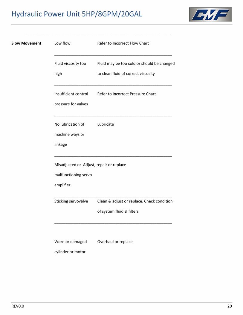
___________________________________________________________________
Slow Movement Low flow Refer to Incorrect Flow Chart
______________________________________________________
Fluid viscosity too Fluid may be too cold or should be changed
high to clean fluid of correct viscosity
______________________________________________________
Insufficient control Refer to Incorrect Pressure Chart
pressure for valves
______________________________________________________
No lubrication of Lubricate
machine ways or
linkage
______________________________________________________
Misadjusted or Adjust, repair or replace
malfunctioning servo
amplifier
______________________________________________________ Sticking servovalve Clean & adjust or replace. Check condition
of system fluid & filters
______________________________________________________
Worn or damaged Overhaul or replace
cylinder or motor
Hydraulic Power Unit 5HP/8GPM/20GAL
REV0.0 21
___________________________________________________________________
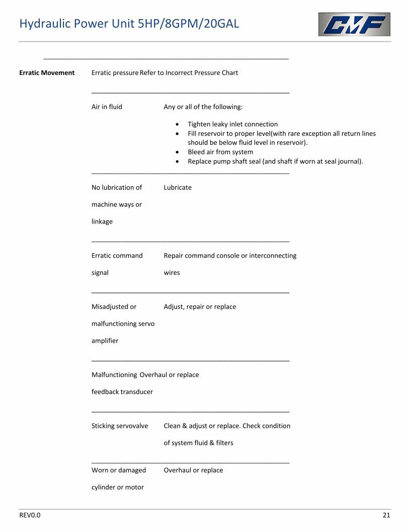
Erratic Movement Erratic pressure Refer to Incorrect Pressure Chart
______________________________________________________
Air in fluid Any or all of the following:
• Tighten leaky inlet connection • Fill reservoir to proper level(with rare exception all return lines
should be below fluid level in reservoir). • Bleed air from system • Replace pump shaft seal (and shaft if worn at seal journal).
______________________________________________________
No lubrication of Lubricate
machine ways or
linkage
______________________________________________________
Erratic command Repair command console or interconnecting
signal wires
______________________________________________________
Misadjusted or Adjust, repair or replace
malfunctioning servo
amplifier
______________________________________________________
Malfunctioning Overhaul or replace
feedback transducer
______________________________________________________
Sticking servovalve Clean & adjust or replace. Check condition
of system fluid & filters
______________________________________________________ Worn or damaged Overhaul or replace
cylinder or motor
Hydraulic Power Unit 5HP/8GPM/20GAL
REV0.0 22
___________________________________________________________________
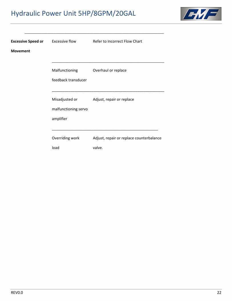
Excessive Speed or Excessive flow Refer to Incorrect Flow Chart
Movement
______________________________________________________
Malfunctioning Overhaul or replace
feedback transducer
______________________________________________________
Misadjusted or Adjust, repair or replace
malfunctioning servo
amplifier
___________________________________________________
Overriding work Adjust, repair or replace counterbalance
load valve.
Hydraulic Power Unit 5HP/8GPM/20GAL
REV0.0 23
Hydraulic Power Unit 5HP/8GPM/20GAL
REV0.0 24
Hydraulic Power Unit 5HP/8GPM/20GAL
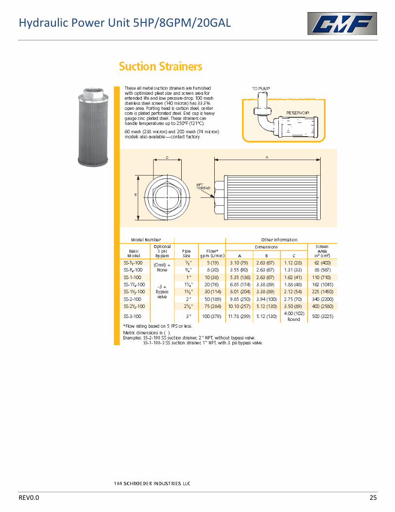
REV0.0 25
Hydraulic Power Unit 5HP/8GPM/20GAL
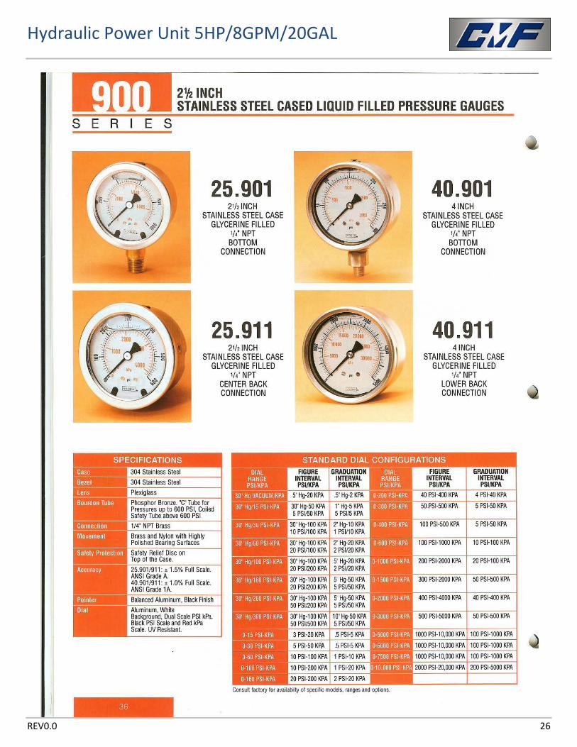
REV0.0 26
Hydraulic Power Unit 5HP/8GPM/20GAL
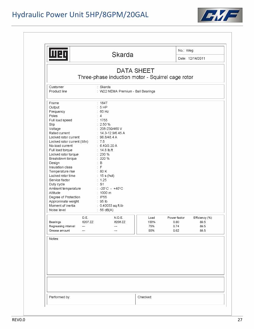
REV0.0 27
Hydraulic Power Unit 5HP/8GPM/20GAL
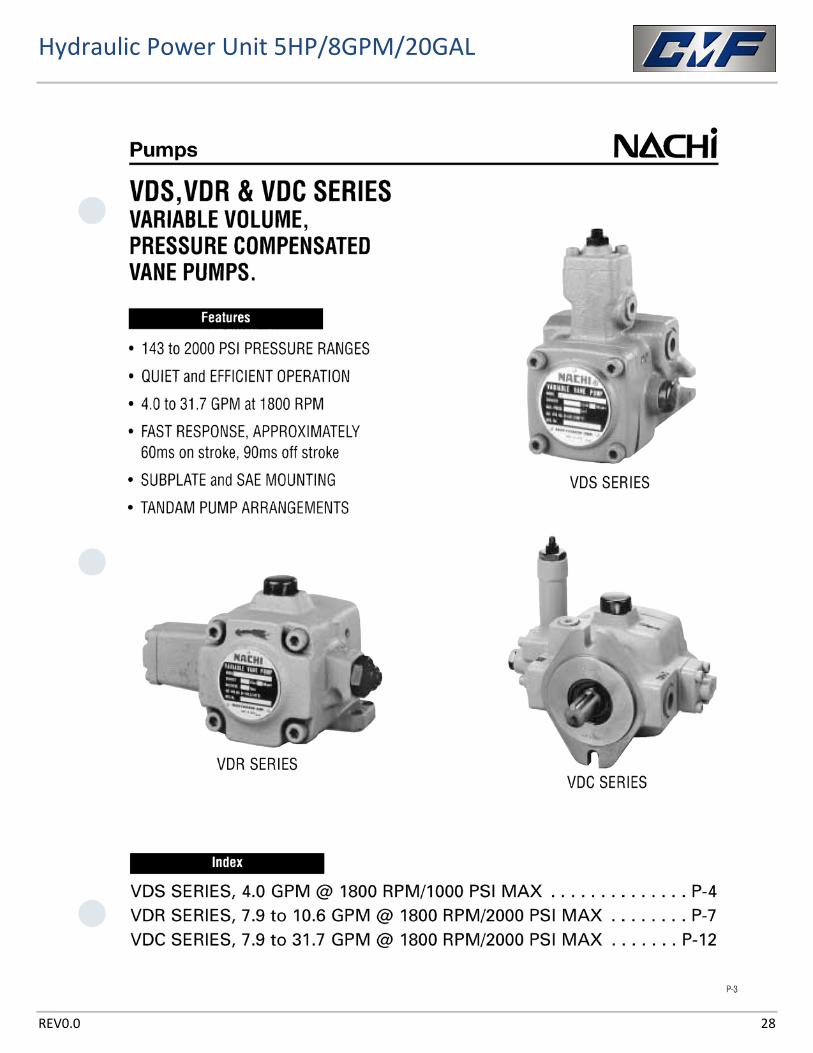
REV0.0 28
Hydraulic Power Unit 5HP/8GPM/20GAL
REV0.0 29
Hydraulic Power Unit 5HP/8GPM/20GAL
REV0.0 30
Hydraulic Power Unit 5HP/8GPM/20GAL
REV0.0 31
Hydraulic Power Unit 5HP/8GPM/20GAL
REV0.0 32
Hydraulic Power Unit 5HP/8GPM/20GAL
REV0.0 33
Hydraulic Power Unit 5HP/8GPM/20GAL
REV0.0 34
Hydraulic Power Unit 5HP/8GPM/20GAL
REV0.0 35
Hydraulic Power Unit 5HP/8GPM/20GAL
REV0.0 36
Hydraulic Power Unit 5HP/8GPM/20GAL
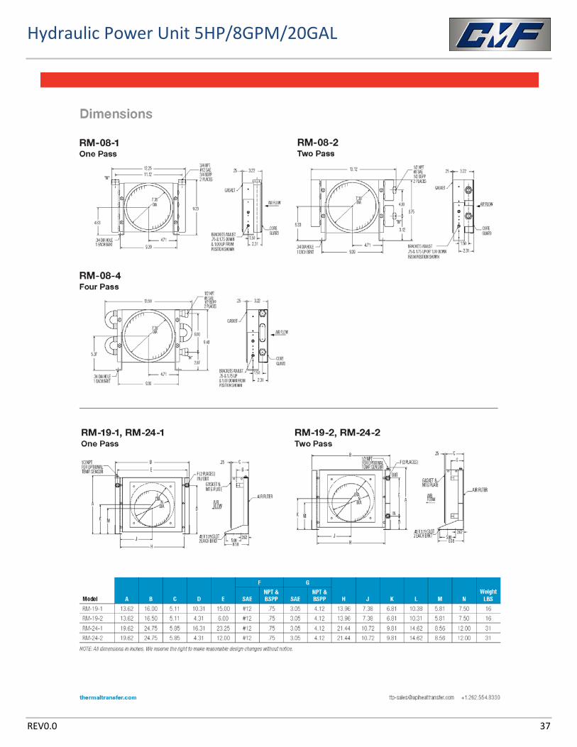
REV0.0 37
Hydraulic Power Unit 5HP/8GPM/20GAL
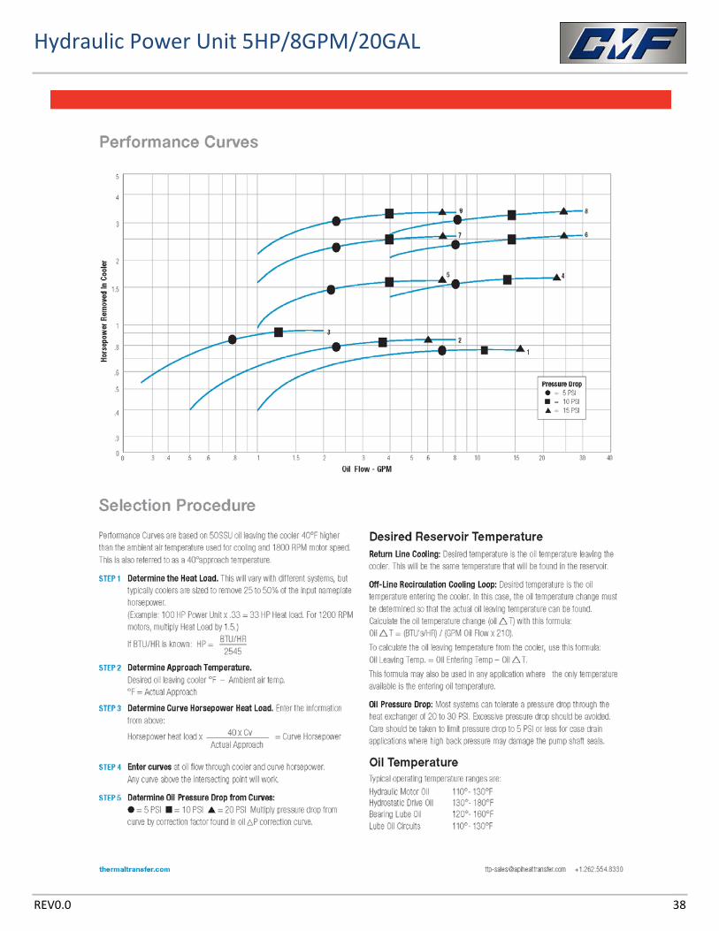
REV0.0 38
Hydraulic Power Unit 5HP/8GPM/20GAL
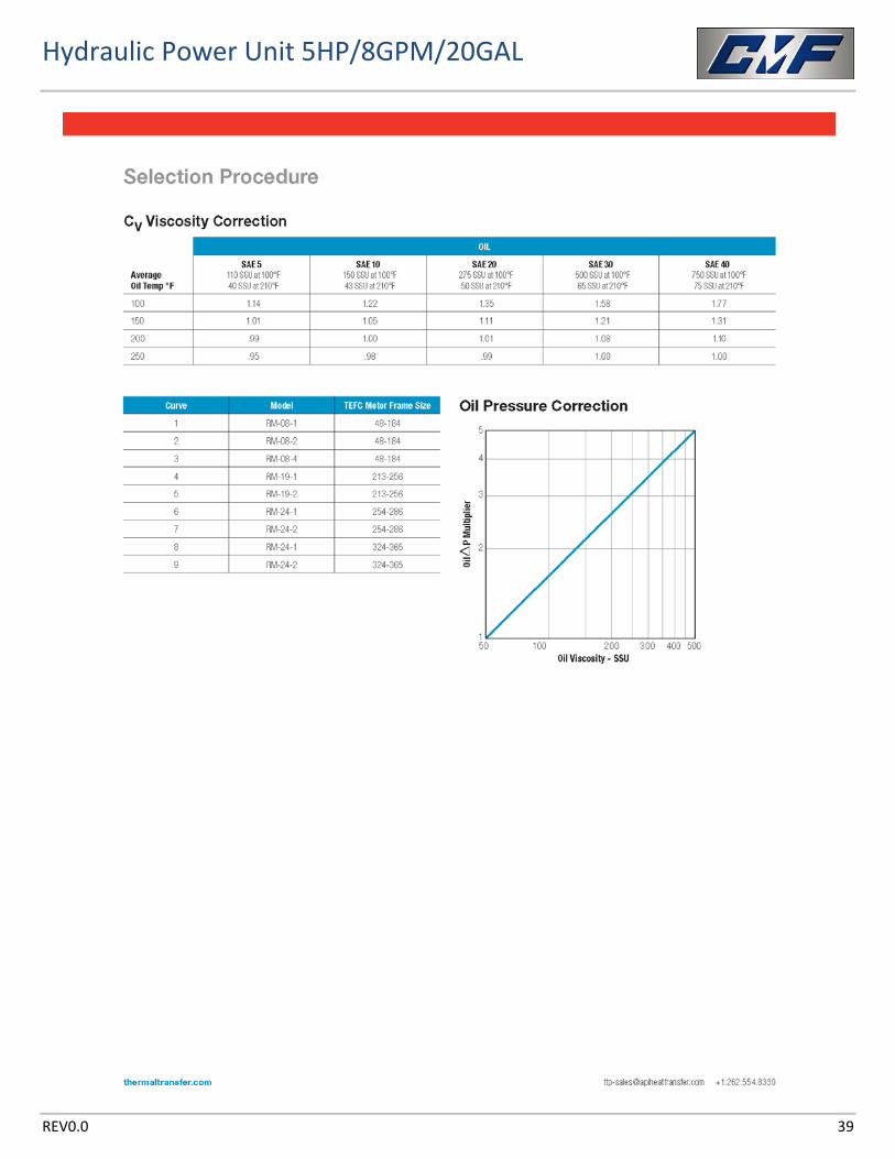
REV0.0 39
Hydraulic Power Unit 5HP/8GPM/20GAL
REV0.0 40
Custom Metal Fabricators Inc. 3194 R Ave.
Herington, KS 67449 Phone: 785-258-3744
www.cmfmfg.com