hydronic residential - home | compac, climaveneta ... · climaveneta. brand of mitsubishi electric...
TRANSCRIPT

HYDRONIC RESIDENTIAL
This document can be subjected to variations. Descriptions, performance data, images and diagrams are indicative only and refer to the standard installation in the EU.For further information contact Mitsubishi Electric Hydronics & IT Cooling Systems Comunications/Marketing Department or visit www.climaveneta.com
Chillers, reversible heat pumps and modular units for small and medium applications.Climaveneta. brand of Mitsubishi Electric Hydronics & IT Cooling Systems, presents the mini chiller range: cooling only and reversible units, air cooled and water cooled type, designed to provide customers with a top efficiency answer to any requirement of small and medium installations.

3
BRAT2 0021÷0121 pg. 4Air source chillers for outdoor installation 5,74-31,7 kW
MICS 0072÷0182 pg. 6Modular air source chillers for outdoor installation 18,2-44,7 kW
BRA2 0021÷0061 pg. 8Air source chillers for indoor installation 5,74-15,7 kW
MICS-C 0072÷0122 pg. 10Air source chillers for indoor installation 18,2-31,9 kW
BRH 0011÷0121 pg. 12Water cooled chillers 5,50-35,1 kW
HE+NHCR 0011÷0121 pg. 16Condenserless units coupled with remote condenser
4,70-32,4 kW
BRAN2 0021÷0121 pg. 18Air source reversible units for outdoor installation 4,81-27,2 kW
MICS-N 0072÷0182 pg. 22Modular reversible units, air source for outdoor installation 17,3-42,5 kW
BRN2 0021÷0061 pg. 26Reversible units, air source for indoor installation 4,81-13,1 kW
MICS-CN 0072÷0122 pg. 28Reversible units, air source for indoor installation 17,3-30,3 kW
BRAT-MC 0011÷0121 pg. 30Condensing units 5,61-33,4 kW
HYDRONIC RESIDENTIAL
4
Hydr
onic
resid
entia
l
BRAT2 0021÷0121
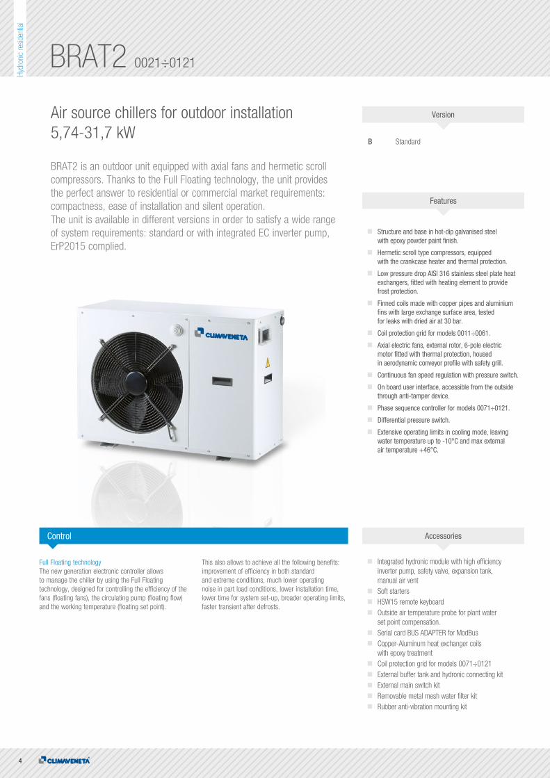
Air source chillers for outdoor installation 5,74-31,7 kW
BRAT2 is an outdoor unit equipped with axial fans and hermetic scrollcompressors. Thanks to the Full Floating technology, the unit provides the perfect answer to residential or commercial market requirements: compactness, ease of installation and silent operation. The unit is available in different versions in order to satisfy a wide range of system requirements: standard or with integrated EC inverter pump, ErP2015 complied.
B Standard
Structure and base in hot-dip galvanised steel with epoxy powder paint finish.
Hermetic scroll type compressors, equipped with the crankcase heater and thermal protection.
Low pressure drop AISI 316 stainless steel plate heat exchangers, fitted with heating element to provide frost protection.
Finned coils made with copper pipes and aluminium fins with large exchange surface area, tested for leaks with dried air at 30 bar.
Coil protection grid for models 0011÷0061.
Axial electric fans, external rotor, 6-pole electric motor fitted with thermal protection, housed in aerodynamic conveyor profile with safety grill.
Continuous fan speed regulation with pressure switch.
On board user interface, accessible from the outside through anti-tamper device.
Phase sequence controller for models 0071÷0121.
Differential pressure switch.
Extensive operating limits in cooling mode, leaving water temperature up to -10°C and max external air temperature +46°C.
Full Floating technologyThe new generation electronic controller allows to manage the chiller by using the Full Floating technology, designed for controlling the efficiency of the fans (floating fans), the circulating pump (floating flow) and the working temperature (floating set point).
This also allows to achieve all the following benefits: improvement of efficiency in both standard and extreme conditions, much lower operating noise in part load conditions, lower installation time, lower time for system set-up, broader operating limits, faster transient after defrosts.
Integrated hydronic module with high efficiency inverter pump, safety valve, expansion tank, manual air vent
Soft starters HSW15 remote keyboard Outside air temperature probe for plant water
set point compensation. Serial card BUS ADAPTER for ModBus Copper-Aluminum heat exchanger coils
with epoxy treatment Coil protection grid for models 0071÷0121 External buffer tank and hydronic connecting kit External main switch kit Removable metal mesh water filter kit Rubber anti-vibration mounting kit
Control Accessories
Features
Version

5
Hydr
onic
resid
entia
l
H
BA
PLATESAXIALSCROLLCOOLING
Technical data
BRAT2 0021 0025 0031 0041 0021 0025 0031Power supply V/ph/Hz 230/1/50 230/1/50 230/1/50 230/1/50 400/3/50 400/3/50 400/3/50
PERFORMANCE
COOLING ONLY (GROSS VALUE)
Cooling capacity (1) kW 5,76 7,06 8,71 11,5 5,74 7,13 8,79
Total power input (1) kW 2,08 2,58 3,49 4,10 2,04 2,43 3,21
EER (1) kW/kW 2,77 2,74 2,50 2,80 2,81 2,93 2,74
ESEER (1) kW/kW 3,36 3,38 3,11 3,30 3,49 3,63 3,30
COOLING ONLY (EN14511 VALUE)
Cooling capacity (1)(2) kW 5,74 7,03 8,68 11,4 5,72 7,10 8,76
EER (1)(2) kW/kW 2,73 2,70 2,46 2,74 2,77 2,89 2,70
ESEER (1)(2) kW/kW 3,31 3,32 3,06 3,21 3,43 3,57 3,26
Cooling energy class C C E C C C C
EXCHANGERS
HEAT EXCHANGER USER SIDE IN REFRIGERATION
Water flow (1) m³h 0,99 1,22 1,50 1,97 0,99 1,23 1,51
Pressure drop (1) kPa 6,87 8,27 9,00 17,9 6,84 8,44 9,16
REFRIGERANT CIRCUIT
No. Compressors N° 1 1 1 1 1 1 1
No. Circuits N° 1 1 1 1 1 1 1
NOISE LEVEL
Sound pressure (3) dB(A) 52 52 52 54 52 52 52
Sound power level in cooling (4)(5) dB(A) 66 66 66 69 66 66 66
SIZE AND WEIGHT
A (6) mm 900 900 900 900 900 900 900
B (6) mm 370 370 370 370 370 370 370
H (6) mm 640 940 940 1240 640 940 940
Operating weight (6) kg 85 100 105 126 85 100 105
BRAT2 0041 0051 0061 0071 0091 0101 0121Power supply V/ph/Hz 400/3/50 400/3/50 400/3/50 400/3/50 400/3/50 400/3/50 400/3/50
PERFORMANCE
COOLING ONLY (GROSS VALUE)
Cooling capacity (1) kW 11,9 13,4 15,7 19,1 21,7 26,7 31,7
Total power input (1) kW 4,24 4,70 5,31 6,69 8,13 8,91 11,8
EER (1) kW/kW 2,81 2,85 2,96 2,86 2,67 3,00 2,69
ESEER (1) kW/kW 3,40 3,26 3,48 3,33 3,14 3,50 3,18
COOLING ONLY (EN14511 VALUE)
Cooling capacity (1)(2) kW 11,8 13,3 15,6 19,0 21,6 26,6 31,5
EER (1)(2) kW/kW 2,74 2,79 2,89 2,79 2,62 2,93 2,64
ESEER (1)(2) kW/kW 3,30 3,18 3,39 3,25 3,08 3,42 3,11
Cooling energy class C C C C D B D
EXCHANGERS
HEAT EXCHANGER USER SIDE IN REFRIGERATION
Water flow (1) m³h 2,06 2,31 2,69 3,29 3,74 4,60 5,46
Pressure drop (1) kPa 19,4 20,0 19,6 22,2 22,3 23,3 25,3
REFRIGERANT CIRCUIT
No. Compressors N° 1 1 1 1 1 1 1
No. Circuits N° 1 1 1 1 1 1 1
NOISE LEVEL
Sound pressure (3) dB(A) 54 54 54 59 59 60 60
Sound power level in cooling (4)(5) dB(A) 69 69 69 74 74 76 76
SIZE AND WEIGHT
A (6) mm 900 900 900 1450 1450 1450 1450
B (6) mm 370 370 370 550 550 550 550
H (6) mm 1240 1240 1390 1200 1200 1700 1700
Operating weight (6) kg 126 145 155 245 249 320 325
Notes:1 Plant (side) cooling exchanger water (in/out) 12°C/7°C; Source (side) heat exchanger air (in) 35°C.2 Values in compliance with EN14511-3:2013.3 Average sound pressure level at 1m distance, unit in a free field on a reflective surface; non-binding value calculated from the sound power level.4 Sound power on the basis of measurements made in compliance with ISO 9614.5 Sound power level in cooling, outdoors.6 Unit in standard configuration/execution, without optional accessories.
Certified data in EUROVENT
The units highlighted in this publication contain HFC R410A [GWP100
2088] fluorinated greenhouse gases.

6
Hydr
onic
resid
entia
l
MICS 0072÷0182
Modular air source chillers for outdoorinstallation 18,2-44,7 kW
MICS is the air cooled range of outdoor units with axial fans, hermetic scroll compressors and Full Floating technology. MICS units provide the perfect answer to the most common residential market requirements: compactness, ease of installation and silent operation.
FF Standard version, with built-in hydronic kitFFT Standard version without hydronic kit
Structure and base in hot-dip galvanised steel with epoxy powder paint finish.
Low pressure drop AISI 316 stainless steel plate heat exchangers, fitted with heating element to provide frost protection.
External access to the controller through anti-tamper device.
Finned coils made with copper pipes and aluminium fins with large exchange surface area, tested for leaks with dried air at 30 bar.
User interface with display.
Electronic expansion valve.
Available water pipe fittings in case of installation under appliance.
Differential pressure switch.
Drain valve.
The hydronic circuit on the FF models includes: - Multistage centrifugal pump - Air vent valve - Expansion tank - Safety valve - Pressure gauge
Modular designMICS features an innovative design that optimises the possibilities of connecting up several units, reducing the overall footprint of the units.
Better capacity controlThe possibility of controlling up to six units as a single product means that MICS can increase the number of available control steps, thereby ensuring practically perfect adaptation to the real heat load trend.
Keyboard Master ControlKMC is the central control of the cascade modules. Its main function is to supervise operation of all the modules, making them operate synergically. As a user interface it has a graphic display and a keypad for navigating all the pages.
Full Floating technologyThe full floating technology with automatic control of the airflow rate, water flow rate and water temperature gains a new function: Flex Energy,used to manage the capacity control steps in linear or alternating sequence in installations with several modules.
Rubber anti-vibration mounting kit
Removable metal mesh water filter kit
Kit for connecting the KMC keyboard
Coil protection grids
KMC keyboard for modular system
Remote control kit
Control Accessories
Features
Version

7
Hydr
onic
resid
entia
l
PLATESAXIALSCROLLCOOLING
Technical data
BA
H
MICS/FF 0072 0092 0122 0152 0182Power supply V/ph/Hz 400/3/50 400/3/50 400/3/50 400/3/50 400/3/50
PERFORMANCE
COOLING ONLY (GROSS VALUE)
Cooling capacity (1) kW 18,2 23,0 31,9 39,4 44,7
Total power input (1) kW 6,50 9,30 10,7 13,4 15,5
EER (1) kW/kW 2,80 2,47 2,98 2,94 2,88
ESEER (1) kW/kW 4,05 3,93 3,98 4,12 4,17
COOLING ONLY (EN14511 VALUE)
Cooling capacity (1)(2) kW 18,3 23,1 32,0 39,6 44,9
EER (1)(2) kW/kW 2,61 2,38 2,88 2,89 2,82
ESEER (1)(2) kW/kW 3,44 3,56 3,69 3,94 3,94
Cooling energy class D E C C C
EXCHANGERS
HEAT EXCHANGER USER SIDE IN REFRIGERATION
Water flow (1) m³h 3,13 3,96 5,49 6,78 7,70
Available unit's head (1) kPa 124,8 143,1 101,5 113,8 133,8
REFRIGERANT CIRCUIT
No. Compressors N° 2 2 2 2 2
No. Circuits N° 1 1 1 1 1
NOISE LEVEL
Sound pressure (3) dB(A) 64 64 66 66 66
Sound power level in cooling (4)(5) dB(A) 80 80 83 83 83
SIZE AND WEIGHT
A (6) mm 1040 1040 1630 1630 1630
B (6) mm 790 790 790 790 790
H (6) mm 1725 1725 1725 1725 1725
Operating weight (6) kg 310 330 410 450 480
MICS/FFT 0072 0092 0122 0152 0182Power supply V/ph/Hz 400/3/50 400/3/50 400/3/50 400/3/50 400/3/50
PERFORMANCE
COOLING ONLY (GROSS VALUE)
Cooling capacity (1) kW 18,2 23,0 31,9 39,4 44,7
Total power input (1) kW 6,50 9,30 10,7 13,4 15,5
EER (1) kW/kW 2,80 2,47 2,98 2,94 2,88
ESEER (1) kW/kW 4,05 3,93 3,98 4,12 4,17
COOLING ONLY (EN14511 VALUE)
Cooling capacity (1)(2) kW 18,1 22,9 31,7 39,2 44,4
EER (1)(2) kW/kW 2,73 2,42 2,90 2,87 2,81
ESEER (1)(2) kW/kW 3,83 3,74 3,78 3,92 3,93
EXCHANGERS
HEAT EXCHANGER USER SIDE IN REFRIGERATION
Water flow (1) m³/h 3,13 3,96 5,49 6,78 7,70
Pressure drop (1) kPa 29,3 28,2 36,2 35,9 45,0
REFRIGERANT CIRCUIT
No. Compressors N° 2 2 2 2 2
No. Circuits N° 1 1 1 1 1
NOISE LEVEL
Sound pressure (3) dB(A) 64 64 66 66 66
Sound power level in cooling (4)(5) dB(A) 80 80 83 83 83
SIZE AND WEIGHT
A (6) mm 1040 1040 1630 1630 1630
B (6) mm 790 790 790 790 790
H (6) mm 1725 1725 1725 1725 1725
Operating weight (6) kg 310 330 410 450 480
Notes:1 Plant (side) cooling exchanger water (in/out) 12°C/7°C; Source (side) heat exchanger air (in) 35°C.2 Values in compliance with EN14511-3:2013.3 Average sound pressure level at 1m distance, unit in a free field on a reflective surface; non-binding value calculated from the sound power level.4 Sound power on the basis of measurements made in compliance with ISO 9614.5 Sound power level in cooling, outdoors.6 Unit in standard configuration/execution, without optional accessories.
Certified data in EUROVENT
The units highlighted in this publication contain HFC R410A [GWP100
2088] fluorinated greenhouse gases.

8
Hydr
onic
resid
entia
l
BRA2 0021÷0061
Air source chillers for indoor installation5,74-15,7 kW
BRA2 are air-cooled liquid chillers with hermetic scroll compressors and Full Floating technology. Thanks to an advanced electronic control, BRA2 units represent the perfect answer to residential market requirements: compactness, ease of installation and silent operation. BRA2 can be installed indoor thanks to the radial plug fans provided as standard and the possibility of ducting the air flow either vertically or horizontally. Two configurations are available to satisfy a wide range of system requirements: standard version, or with integrated EC inverter pump, ErP2015 complied.
B Standard
Structure and base in hot-dip galvanised steel with epoxy powder paint finish.
Hermetic scroll type compressors, equipped with the crankcase heater and thermal protection.
Low pressure drop AISI 316 stainless steel plate heat exchangers, fitted with heating element to provide frost protection.
Finned coils made with copper pipes and aluminium fins with large exchange surface area, tested for leaks with dried air at 30 bar.
Coil protection grid for models 0011÷0061.
Radial plug fan.
Continuous fan speed regulation with pressure switch.
On board user interface, accessible from the outside through anti-tamper device.
Differential pressure switch.
Extensive operating limits in cooling mode, leaving water temperature up to -10°C and max external air temperature +46°C.
Full Floating technologyThe new generation electronic controller allows to manage the chiller by using the Full Floating technology, designed for controlling the efficiency of the fans (floating fans), the circulating pump (floating flow) and the working temperature (floating set point).
This also allows to achieve all the following benefits: improvement of efficiency in both standard and extreme conditions, much lower operating noise in part load conditions, lower installation time, lower time for system set-up, broader operating limits, faster transient after defrosts.
Integrated hydronic module with high efficiency inverter pump, safety valve, expansion tank, manual air vent
Soft starters
HSW15 remote keyboard
Outside air temperature probe for plant water set point compensation.
Serial card BUS ADAPTER for ModBus
Copper-Copper heat exchanger coils
Copper-Aluminum heat exchanger coils with epoxy treatment
External buffer tank and hydronic connecting kit
External main switch kit
Removable metal mesh water filter kit
Rubber anti-vibration mounting kit
Control Accessories
Features
Version

9
Hydr
onic
resid
entia
l
PLATESCENTRIFUGALSCROLLCOOLING
B
H
A
Technical data
BRA2 0021 0025 0031 0041 0021 0025 0031 0041 0051 0061Power supply V/ph/Hz 230/1/50 230/1/50 230/1/50 230/1/50 400/3/50 400/3/50 400/3/50 400/3/50 400/3/50 400/3/50
PERFORMANCE
COOLING ONLY (GROSS VALUE)
Cooling capacity (1) kW 5,76 7,06 8,71 11,5 5,74 7,13 8,79 11,9 13,4 15,7
Total power input (1) kW 2,43 2,93 3,84 4,80 2,39 2,78 3,56 4,94 5,40 6,01
EER (1) kW/kW 2,37 2,41 2,27 2,40 2,40 2,56 2,47 2,41 2,48 2,61
ESEER (1) kW/kW 2,77 2,88 2,76 2,73 2,86 3,08 2,91 2,81 2,77 3,00
COOLING ONLY (EN14511 VALUE)
Cooling capacity (1)(2) kW 5,74 7,03 8,68 11,4 5,72 7,10 8,76 11,8 13,3 15,6
EER (1)(2) kW/kW 2,59 2,62 2,41 2,63 2,63 2,80 2,64 2,64 2,66 2,80
ESEER (1)(2) kW/kW 3,11 3,22 2,98 3,06 3,21 3,45 3,16 3,13 3,02 3,26
Cooling energy class B B C B B A B B B A
EXCHANGERS
HEAT EXCHANGER USER SIDE IN REFRIGERATION
Water flow (1) m³/h 0,99 1,22 1,50 1,97 0,99 1,23 1,51 2,06 2,31 2,69
Pressure drop (1) kPa 6,87 8,27 9,00 17,9 6,84 8,44 9,16 19,4 20,0 19,6
REFRIGERANT CIRCUIT
No. Compressors N° 1 1 1 1 1 1 1 1 1 1
No. Circuits N° 1 1 1 1 1 1 1 1 1 1
FANS
Air flow m³/s 0,81 0,93 0,93 1,77 0,81 0,93 0,93 1,77 1,61 1,74
Available static pressure Pa 120 120 120 120 120 120 120 120 120 120
NOISE LEVEL
Sound power level in cooling (3)(4) dB(A) 75 75 75 77 75 75 75 77 77 77
SIZE AND WEIGHT
A (5) mm 900 900 900 900 900 900 900 900 900 900
B (5) mm 580 580 580 0580 580 580 580 580 580 630
H (5) mm 640 940 940 1240 640 940 940 1240 1240 1390
Operating weight (5) kg 105 120 125 165 105 120 125 165 185 195
Notes:1 Plant (side) cooling exchanger water (in/out) 12°C/7°C; Source (side) heat exchanger air (in) 35°C.2 Values in compliance with EN14511-3:2013.3 Total sound power of fans, as declared by the maker, at the rated speed of rotation and a useful static head of 120 Pa on the delivery side.4 Sound power level in cooling, outdoors.5 Unit in standard configuration/execution, without optional accessories.
Certified data in EUROVENT
The units highlighted in this publication contain HFC R410A [GWP100
2088] fluorinated greenhouse gases.

10
Hydr
onic
resid
entia
l
MICS-C 0072÷0122
Air source chillers for indoor installation18,2-31,9 kW
MICS-C are indoor air-cooled chillers with hermetic scroll compressors and Full Floating technology. Thanks to an advanced electronic control, these units represent the perfect answer to residential market requirements: compactness, ease of installation and silent operation.
FF Standard version, with built-in hydronic kit
Structure and base in hot-dip galvanised steel with epoxy powder paint finish.
Low pressure drop AISI 316 stainless steel plate heat exchangers, fitted with heating element to provide frost protection.
Control with anti-tamper device accessible from the outside.
Finned coils made with copper pipes and aluminium fins with large exchange surface area, tested for leaks with dried air at 30 bar.
User interface with display.
Electronic expansion valve.
Available water pipe fittings.
The circuit includes: - Multistage centrifugal pump - Air vent valve - Differential pressure switch. - Expansion tank - Safety valve - Pressure gauge - Drain valve.
Full Floating technologyThe new generation electronic controller allows to manage the chiller by using the Full Floating technology, designed for controlling the efficiency of the fans (floating fans), the circulating pump (floating flow) and the working temperature (floating set point).
This also allows to achieve all the following benefits: improvement of efficiency in both standard and extreme conditions, much lower operating noise in part load conditions, lower installation time, lower time for system set-up, broader operating limits, faster transient after defrosts.
Rubber anti-vibration mounting kit
Removable metal mesh water filter kit
Coil protection grids
Remote control kit
Control Accessories
Features
Version

11
Hydr
onic
resid
entia
l
PLATESCENTRIFUGALSCROLLCOOLING
A
H
B
MICS-C/FF 0072 0092 0122Power supply V/ph/Hz 400/3/50 400/3/50 400/3/50
PERFORMANCE
COOLING ONLY (GROSS VALUE)
Cooling capacity (1) kW 18,2 23,0 31,9
Total power input (1) kW 6,50 9,30 10,7
EER (1) kW/kW 2,80 2,47 2,98
ESEER (1) kW/kW 4,05 3,93 3,98
COOLING ONLY (EN14511 VALUE)
Cooling capacity (1)(2) kW 18,3 23,1 32,0
EER (1)(2) kW/kW 3,05 2,66 3,51
ESEER (1)(2) kW/kW 4,48 4,29 5,04
Cooling energy class A B A
EXCHANGERS
HEAT EXCHANGER USER SIDE IN REFRIGERATION
Water flow (1) m³/h 3,13 3,96 5,49
Available unit's head (1) kPa 124,8 143,1 101,5
REFRIGERANT CIRCUIT
No. Compressors N° 2 2 2
No. Circuits N° 1 1 1
FANS
Air flow m³/s 2,50 2,50 5,00
Available static pressure Pa 120 120 120
NOISE LEVEL
Sound power level in cooling (3)(4) dB(A) 86 86 89
SIZE AND WEIGHT
A (5) mm 1040 1040 1630
B (5) mm 790 790 790
H (5) mm 2000 2000 2000
Operating weight (5) kg 330 350 450
Notes:1 Plant (side) cooling exchanger water (in/out) 12°C/7°C; Source (side) heat exchanger air (in) 35°C.2 Values in compliance with EN14511-3:2013.3 Total sound power of fans, as declared by the maker, at the rated speed of rotation and a useful static head of 120 Pa on the delivery side.4 Sound power level in cooling, indoors.5 Unit in standard configuration/execution, without optional accessories.
Certified data in EUROVENT
The units highlighted in this publication contain HFC R410A [GWP100
2088] fluorinated greenhouse gases.
Technical data
12
Hydr
onic
resid
entia
l
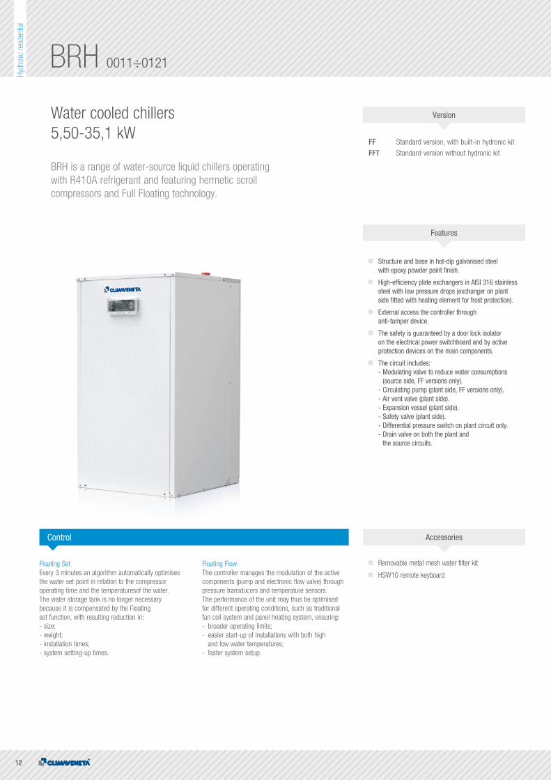
BRH 0011÷0121
Water cooled chillers5,50-35,1 kW
BRH is a range of water-source liquid chillers operating with R410A refrigerant and featuring hermetic scroll compressors and Full Floating technology.
FF Standard version, with built-in hydronic kitFFT Standard version without hydronic kit
Structure and base in hot-dip galvanised steel with epoxy powder paint finish.
High-efficiency plate exchangers in AISI 316 stainless steel with low pressure drops (exchanger on plant side fitted with heating element for frost protection).
External access the controller through anti-tamper device.
The safety is guaranteed by a door lock isolator on the electrical power switchboard and by active protection devices on the main components.
The circuit includes: - Modulating valve to reduce water consumptions (source side, FF versions only). - Circulating pump (plant side, FF versions only). - Air vent valve (plant side). - Expansion vessel (plant side). - Safety valve (plant side). - Differential pressure switch on plant circuit only. - Drain valve on both the plant and the source circuits.
Floating SetEvery 3 minutes an algorithm automatically optimises the water set point in relation to the compressor operating time and the temperaturesof the water. The water storage tank is no longer necessary because it is compensated by the Floating set function, with resulting reduction in:- size;- weight;- installation times;- system setting-up times.
Floating FlowThe controller manages the modulation of the active components (pump and electronic flow valve) through pressure transducers and temperature sensors. The performance of the unit may thus be optimised for different operating conditions, such as traditional fan coil system and panel heating system, ensuring:- broader operating limits;- easier start-up of installations with both high and low water temperatures;- faster system setup.
Removable metal mesh water filter kit
HSW10 remote keyboard
Control Accessories
Features
Version

13
Hydr
onic
resid
entia
l
Notes:1 Plant (side) cooling exchanger water (in/out) 12°C/7°C; Source (side) heat exchanger water (in/out) 30°C/35°C.2 Values in compliance with EN14511-3:2013.3 Average sound pressure level at 1m distance, unit in a free field on a reflective surface; non-binding value calculated from the sound power level.4 Sound power on the basis of measurements made in compliance with ISO 9614.5 Sound power level in cooling, indoors.6 Unit in standard configuration/execution, without optional accessories.
Certified data in EUROVENT
The units highlighted in this publication contain HFC R410A [GWP100
2088] fluorinated greenhouse gases.
PLATESSCROLLCOOLING
A B
H
Technical data
BRH/FF 0011 0021 0025 0031 0041 0021 0025 0031Power supply V/ph/Hz 230/1/50 230/1/50 230/1/50 230/1/50 230/1/50 400/3/50 400/3/50 400/3/50
PERFORMANCE
COOLING ONLY (GROSS VALUE)
Cooling capacity (1) kW 5,50 5,90 7,60 9,20 11,9 5,90 7,70 9,30
Total power input (1) kW 1,50 1,70 2,00 2,60 3,20 1,60 1,90 2,40
EER (1) kW/kW 3,67 3,47 3,80 3,54 3,72 3,69 4,05 3,88
ESEER (1) kW/kW 4,23 3,92 4,47 4,15 4,10 4,00 4,61 4,38
COOLING ONLY (EN14511 VALUE)
Cooling capacity (1)(2) kW 5,51 5,91 7,61 9,21 11,9 5,91 7,71 9,31
EER (1)(2) kW/kW 3,34 3,19 3,54 3,32 3,38 3,38 3,76 3,61
ESEER (1)(2) kW/kW 3,77 3,54 4,09 3,83 3,67 3,69 4,21 4,03
Cooling energy class F F E F F F E E
EXCHANGERS
HEAT EXCHANGER USER SIDE IN REFRIGERATION
Water flow (1) m³/h 0,95 1,02 1,31 1,58 2,05 1,02 1,33 1,60
Available unit's head (1) kPa 60,3 58,8 65,5 58,5 89,2 58,8 65,1 58,0
Water flow (1) m³/h 1,20 1,30 1,64 2,02 2,58 1,28 1,64 2,00
Pressure drop (1) kPa 13,4 15,6 20,0 29,5 33,4 15,2 20,0 29,0
REFRIGERANT CIRCUIT
No. Compressors N° 1 1 1 1 1 1 1 1
No. Circuits N° 1 1 1 1 1 1 1 1
NOISE LEVEL
Sound pressure (3) dB(A) 38 38 39 39 44 38 39 39
Sound power level in cooling (4)(5) dB(A) 52 52 53 53 58 52 53 53
SIZE AND WEIGHT
A (6) mm 575 575 575 575 575 575 575 575
B (6) mm 560 560 560 560 560 560 560 560
H (6) mm 980 980 980 980 980 980 980 980
Operating weight (6) kg 148 148 150 155 170 148 150 152
BRH/FF 0041 0051 0061 0071 0091 0101 0121Power supply V/ph/Hz 400/3/50 400/3/50 400/3/50 400/3/50 400/3/50 400/3/50 400/3/50
PERFORMANCE
COOLING ONLY (GROSS VALUE)
Cooling capacity (1) kW 12,4 13,9 16,5 20,8 24,0 27,3 35,1
Total power input (1) kW 3,20 3,80 4,00 5,10 5,80 6,80 8,40
EER (1) kW/kW 3,88 3,66 4,13 4,08 4,14 4,01 4,18
ESEER (1) kW/kW 4,28 4,22 4,74 4,62 4,84 4,55 4,59
COOLING ONLY (EN14511 VALUE)
Cooling capacity (1)(2) kW 12,4 13,9 16,5 20,8 24,1 27,4 35,4
EER (1)(2) kW/kW 3,52 3,38 3,82 3,83 3,93 3,68 3,86
ESEER (1)(2) kW/kW 3,82 3,83 4,31 4,28 4,54 4,03 4,17
Cooling energy class E F E E D E D
EXCHANGERS
HEAT EXCHANGER USER SIDE IN REFRIGERATION
Water flow (1) m³/h 2,13 2,39 2,84 3,58 4,13 4,70 6,04
Available unit's head (1) kPa 87,0 87,1 81,9 74,4 73,6 125,3 166
Water flow (1) m³/h 2,67 3,03 3,51 4,43 5,10 5,84 7,45
Pressure drop (1) kPa 35,7 34,0 36,3 40,0 34,2 46,8 47,7
REFRIGERANT CIRCUIT
No. Compressors N° 1 1 1 1 1 1 1
No. Circuits N° 1 1 1 1 1 1 1
NOISE LEVEL
Sound pressure (3) dB(A) 44 44 45 51 51 55 55
Sound power level in cooling (4)(5) dB(A) 58 58 59 66 66 70 70
SIZE AND WEIGHT
A (6) mm 575 575 575 780 780 780 780
B (6) mm 560 560 560 680 680 680 680
H (6) mm 980 980 980 1150 1150 1150 1150
Operating weight (6) kg 160 170 175 220 230 235 250

14
Hydr
onic
resid
entia
l
Technical data
BRH/FFT 0011 0021 0025 0031 0041 0021 0025 0031Power supply V/ph/Hz 230/1/50 230/1/50 230/1/50 230/1/50 230/1/50 400/3/50 400/3/50 400/3/50
PERFORMANCE
COOLING ONLY (GROSS VALUE)
Cooling capacity (1) kW 5,50 5,90 7,60 9,20 11,9 5,90 7,70 9,30
Total power input (1) kW 1,50 1,70 2,00 2,60 3,20 1,60 1,90 2,40
EER (1) kW/kW 3,67 3,47 3,80 3,54 3,72 3,69 4,05 3,88
ESEER (1) kW/kW 4,23 3,92 4,47 4,15 4,10 4,00 4,61 4,38
COOLING ONLY (EN14511 VALUE)
Cooling capacity (1)(2) kW 5,48 5,87 7,56 9,14 11,8 5,87 7,66 9,24
EER (1)(2) kW/kW 3,51 3,31 3,60 3,32 3,48 3,51 3,82 3,62
ESEER (1)(2) kW/kW 4,01 3,71 4,18 3,85 3,80 3,87 4,31 4,05
EXCHANGERS
HEAT EXCHANGER USER SIDE IN REFRIGERATION
Water flow (1) m³/h 0,95 1,02 1,31 1,58 2,05 1,02 1,33 1,60
Pressure drop (1) kPa 8,41 9,54 12,7 18,2 21,0 9,54 13,0 18,6
Water flow (1) m³/h 1,20 1,30 1,64 2,02 2,58 1,28 1,64 2,00
Pressure drop (1) kPa 13,4 15,6 20,0 29,5 33,4 15,2 20,0 29,0
REFRIGERANT CIRCUIT
No. Compressors N° 1 1 1 1 1 1 1 1
No. Circuits N° 1 1 1 1 1 1 1 1
NOISE LEVEL
Sound pressure (3) dB(A) 38 38 39 39 44 38 39 39
Sound power level in cooling (4)(5) dB(A) 52 52 53 53 58 52 53 53
SIZE AND WEIGHT
A (6) mm 575 575 575 575 575 575 575 575
B (6) mm 560 560 560 560 560 560 560 560
H (6) mm 980 980 980 980 980 980 980 980
Operating weight (6) kg 148 148 150 155 170 148 150 152
BRH/FFT 0041 0051 0061 0071 0091 0101 0121Power supply V/ph/Hz 400/3/50 400/3/50 400/3/50 400/3/50 400/3/50 400/3/50 400/3/50
PERFORMANCE
COOLING ONLY (GROSS VALUE)
Cooling capacity (1) kW 12,4 13,9 16,5 20,8 24,0 27,3 35,1
Total power input (1) kW 3,20 3,80 4,00 5,10 5,80 6,80 8,40
EER (1) kW/kW 3,88 3,66 4,13 4,08 4,14 4,01 4,18
ESEER (1) kW/kW 4,28 4,22 4,74 4,62 4,84 4,55 4,59
COOLING ONLY (EN14511 VALUE)
Cooling capacity (1)(2) kW 12,3 13,8 16,4 20,7 23,9 27,1 34,9
EER (1)(2) kW/kW 3,61 3,44 3,85 3,81 3,90 3,75 3,91
ESEER (1)(2) kW/kW 3,95 3,92 4,37 4,26 4,50 4,13 4,25
EXCHANGERS
HEAT EXCHANGER USER SIDE IN REFRIGERATION
Water flow (1) m³/h 2,13 2,39 2,84 3,58 4,13 4,70 6,04
Pressure drop (1) kPa 22,8 21,3 23,8 26,1 22,5 30,3 31,4
Water flow (1) m³/h 2,67 3,03 3,51 4,43 5,10 5,84 7,45
Pressure drop (1) kPa 35,7 34,0 36,3 40,0 34,2 46,8 47,7
REFRIGERANT CIRCUIT
No. Compressors N° 1 1 1 1 1 1 1
No. Circuits N° 1 1 1 1 1 1 1
NOISE LEVEL
Sound pressure (3) dB(A) 44 44 45 51 51 55 55
Sound power level in cooling (4)(5) dB(A) 58 58 59 66 66 70 70
SIZE AND WEIGHT
A (6) mm 575 575 575 780 780 780 780
B (6) mm 560 560 560 680 680 680 680
H (6) mm 980 980 980 1150 1150 1150 1150
Operating weight (6) kg 160 170 175 220 230 235 250
Notes:1 Plant (side) cooling exchanger water (in/out) 12°C/7°C; Source (side) heat exchanger water (in/out) 30°C/35°C.2 Values in compliance with EN14511-3:2013.3 Average sound pressure level at 1m distance, unit in a free field on a reflective surface; non-binding value calculated from the sound power level.4 Sound power on the basis of measurements made in compliance with ISO 9614.5 Sound power level in cooling, indoors.6 Unit in standard configuration/execution, without optional accessories.
The units highlighted in this publication contain HFC R410A [GWP100
2088] fluorinated greenhouse gases.
BRH 0011÷0121
A B
H

15
Hydr
onic
resid
entia
l
PLATESSCROLLCOOLING
16
Hydr
onic
resid
entia
l
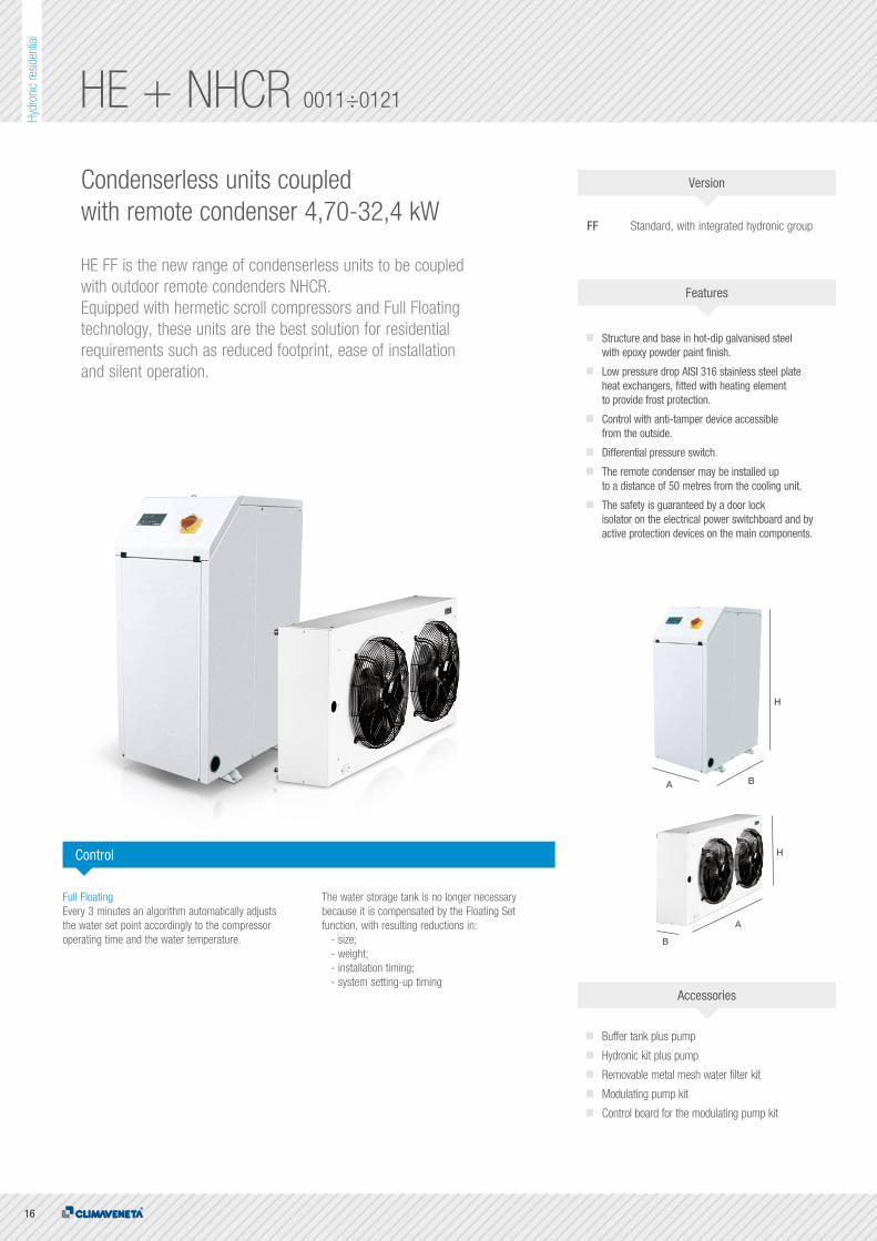
HE + NHCR 0011÷0121
Condenserless units coupled with remote condenser 4,70-32,4 kW
HE FF is the new range of condenserless units to be coupled with outdoor remote condenders NHCR. Equipped with hermetic scroll compressors and Full Floating technology, these units are the best solution for residential requirements such as reduced footprint, ease of installation and silent operation.
FF Standard, with integrated hydronic group
Structure and base in hot-dip galvanised steel with epoxy powder paint finish.
Low pressure drop AISI 316 stainless steel plate heat exchangers, fitted with heating element to provide frost protection.
Control with anti-tamper device accessible from the outside.
Differential pressure switch.
The remote condenser may be installed up to a distance of 50 metres from the cooling unit.
The safety is guaranteed by a door lock isolator on the electrical power switchboard and by active protection devices on the main components.
Full Floating Every 3 minutes an algorithm automatically adjusts the water set point accordingly to the compressor operating time and the water temperature.
The water storage tank is no longer necessary because it is compensated by the Floating Set function, with resulting reductions in: - size; - weight; - installation timing; - system setting-up timing
Buffer tank plus pump
Hydronic kit plus pump
Removable metal mesh water filter kit
Modulating pump kit
Control board for the modulating pump kit
Control
Accessories
Features
Version
A B
H
B
A
H

17
Hydr
onic
resid
entia
l
PLATESSCROLLCOOLING
Technical data
HE/FF 0011 0021 0025 0031 0021 0025 0031Power supply V/ph/Hz 230/1/50 230/1/50 230/1/50 230/1/50 400/3/50 400/3/50 400/3/50
PERFORMANCE
COOLING
Cooling capacity (1) kW 4,70 6,10 7,00 8,20 6,10 7,00 8,20
Total power input (1) kW 1,60 2,10 2,50 2,90 2,10 2,40 2,90
EER (1) kW/kW 2,84 2,89 2,80 2,79 2,94 2,86 2,86
EXCHANGERS
HEAT EXCHANGER USER SIDE IN REFRIGERATION
Water flow (1) m³/h 0,90 1,10 1,30 1,50 1,10 1,30 1,50
Available unit's head (1) kPa 22,0 24,0 26,0 27,0 24,0 26,0 27,0
REFRIGERANT CIRCUIT
No. Compressors N° 1 1 1 1 1 1 1
No. Circuits N° 1 1 1 1 1 1 1
NOISE LEVEL
Sound pressure (2) dB(A) 43 43 48 48 43 48 48
Sound power level in cooling (3) dB(A)
SIZE AND WEIGHT
A (4) mm 450 450 450 450 450 450 450
B (4) mm 400 400 400 400 400 400 400
H (4) mm 960 960 960 960 960 960 960
Operating weight (4) kg 68 70 71 74 70 71 74
HE/FF 0041 0051 0061 0071 0091 0101 0121Power supply V/ph/Hz 400/3/50 400/3/50 400/3/50 400/3/50 400/3/50 400/3/50 400/3/50
PERFORMANCE
COOLING
Cooling capacity (1) kW 10,5 12,5 15,0 19,1 22,2 26,8 32,4
Total power input (1) kW 3,40 4,20 4,90 6,30 7,80 8,90 10,9
EER (1) kW/kW 3,06 2,97 3,07 3,03 2,86 3,00 2,96
EXCHANGERS
HEAT EXCHANGER USER SIDE IN REFRIGERATION
Water flow (1) m³/h 1,90 2,30 2,80 3,40 4,10 4,80 5,90
Available unit's head (1) kPa 19,0 20,0 20,0 23,0 22,0 23,0 23,0
REFRIGERANT CIRCUIT
No. Compressors N° 1 1 1 1 1 1 1
No. Circuits N° 1 1 1 1 1 1 1
NOISE LEVEL
Sound pressure (2) dB(A) 52 52 52 52 52 53 53
Sound power level in cooling (3) dB(A)
SIZE AND WEIGHT
A (4) mm 450 450 450 600 600 600 600
B (4) mm 400 400 400 600 600 600 600
H (4) mm 960 960 960 960 960 960 960
Operating weight (4) kg 85 87 90 177 180 187 190
NHCR 0011-21 0025-31-41 0051 0061 0071-91 0101 0121Power supply V/ph/Hz 230/1/50 230/1/50 230/1/50 230/1/50 230/1/50 230/1/50 230/1/50
PERFORMANCE
NOMINAL SPECIFICATIONS
Rated capacity (1) kW 7,90 15,9 16,3 24,0 25,5 32,7 40,1
No. Circuits N° 1 1 1 1 1 1 1
Total power input (1) kW 0,16 0,32 0,27 0,48 0,54 0,54 0,81
FANS
Air flow m³/h 2267 4535 4899 6802 10330 9798 15500
NOISE LEVEL
Sound pressure (2) dB(A) 33 36 35 38 38 38 40
SIZE AND WEIGHT
A (3) mm 780 1380 1105 1980 2005 2005 2905
H (3) mm 555 555 828 555 828 828 828
B (3) mm 362 362 428 362 428 428 428
Operating weight (3) kg 20 38 43 51 76 84 111
Notes:1 Exchanger air (in) 35 °C; ΔT = 17 K.2 Average sound pressure level, at a distance of 10 m, for units in a free field on a reflecting surface. The average sound pressure level is calculated based on the sound power level measured in accordance with ISO 3744.3 Unit in standard configuration/execution, without optional accessories.
The units highlighted in this publication contain HFC R407C [GWP100
1774] fluorinated greenhouse gases.
Notes:1 Plant (side) cooling exchanger water (in/out) 12°C/7°C; Condensation temperature 47°C.2 Average sound pressure level at 1m distance, unit in a free field on a reflective surface; non-binding value calculated from the sound power level.3 Sound power on the basis of measurements made in compliance with ISO 9614.4 Unit in standard configuration/execution, without optional accessories.
The units highlighted in this publication contain HFC R407C [GWP100
1774] fluorinated greenhouse gases.

18
Hydr
onic
resid
entia
l
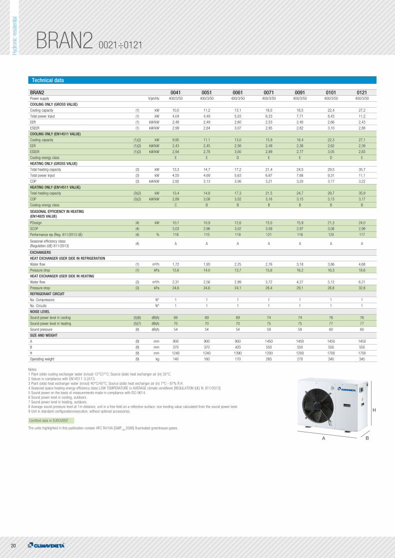
BRAN2 0021÷0121
Air source reversible units for outdoor installation 4,81-27,2 kW
BRAN is the Climaveneta brand range of air-cooled reversible heat pumps equipped with axial fans, hermetic scroll compressors and Full Floating technology. Thanks to the smart electronic control, BRAN units provide the perfect answer to residential or commercial market requirements: compactness, ease of installation and silent operation.The units are available in different versions in order to meet a wide range of system requirements: standard version or with integrated EC inverter pump, ErP2015 complied.
B Standard
Structure and base in hot-dip galvanised steel with epoxy powder paint finish.
Condensate collecting tray for models 0011÷0061.
Hermetic scroll type compressors, equipped with the crankcase heater and thermal protection.
Low pressure drop AISI 316 stainless steel plate heat exchangers, fitted with heating element to provide frost protection.
Finned coils made with copper pipes and aluminium fins with large exchange surface area, tested for leaks with dried air at 30 bar.
Coil protection grid for models 0011÷0061.
Axial electric fans, external rotor, 6-pole electric motor fitted with thermal protection, housed in aerodynamic conveyor profile with safety grill.
Continuous fan speed regulation with pressure switch.
On board user interface, accessible from the outside through anti-tamper device.
Phase sequence controller for models 0071÷0121.
Differential pressure switch.
Extensive operating limits in heating mode, leaving water temperature up to 55°C and down to -10°C, in cooling mode as well, leaving water temperature up to -10°C and max external air temperature 46°C.
Full Floating technologyThe new generation electronic controller allows to manage the chiller by using the Full Floating technology, designed for controlling the efficiency of the fans (floating fans), the circulating pump (floating flow) and the working temperature (floating set point).
This also allows to achieve all the following benefits: improvement of efficiency in both standard and extreme conditions, much lower operating noise in part load conditions, lower installation time, lower time for system set-up, broader operating limits, faster transient after defrosts.
Integrated hydronic module with high efficiency inverter pump, safety valve, expansion tank, manual air vent
Soft starters HSW15 remote keyboard Outside air temperature probe for plant water set point
compensation. Serial card BUS ADAPTER for ModBus Copper-Copper heat exchanger coils Copper-Aluminum heat exchanger coils
with epoxy treatment Condensate collecting tray for models 0071÷0121 Electric heater for condensate collecting tray
to avoid freezing Coil protection grid for models 0071÷0121 External buffer tank and hydronic connecting kit External main switch kit Removable metal mesh water filter kit Rubber anti-vibration mounting kit
Control Accessories
Features
Version

19
Hydr
onic
resid
entia
l
PLATESAXIALSCROLLCOOLINGHEATING
Technical data
BRAN2 0021 0025 0031 0041 0021 0025 0031Power supply V/ph/Hz 230/1/50 230/1/50 230/1/50 230/1/50 400/3/50 400/3/50 400/3/50
COOLING ONLY (GROSS VALUE)
Cooling capacity (1) kW 4,82 5,91 7,31 9,61 4,81 6,01 7,37
Total power input (1) kW 2,00 2,47 3,33 3,91 1,96 2,34 3,04
EER (1) kW/kW 2,41 2,39 2,20 2,46 2,45 2,57 2,42
ESEER (1) kW/kW 2,92 2,96 2,73 2,90 3,02 3,18 2,91
COOLING ONLY (EN14511 VALUE)
Cooling capacity (1)(2) kW 4,81 5,89 7,29 9,56 4,80 5,99 7,35
EER (1)(2) kW/kW 2,38 2,37 2,17 2,42 2,43 2,54 2,40
ESEER (1)(2) kW/kW 2,89 2,92 2,70 2,86 3,00 3,14 2,88
Cooling energy class E E F E E D E
HEATING ONLY (GROSS VALUE)
Total heating capacity (3) kW 6,73 8,33 10,4 12,8 6,70 8,25 10,0
Total power input (3) kW 2,28 2,89 3,52 4,41 2,27 2,74 3,28
COP (3) kW/kW 2,95 2,88 2,95 2,90 2,95 3,01 3,05
HEATING ONLY (EN14511 VALUE)
Total heating capacity (3)(2) kW 6,76 8,37 10,5 12,9 6,73 8,29 10,0
COP (3)(2) kW/kW 2,93 2,86 2,93 2,86 2,93 2,98 3,02
Cooling energy class C C C C C C B
SEASONAL EFFICIENCY IN HEATING
(EN14825 VALUE)
PDesign (4) kW 4,88 6,30 7,47 9,84 4,88 6,02 7,14
SCOP (4) 2,98 3,02 3,01 2,95 3,04 3,14 3,05
Performance ηs (Reg. 811/2013 UE) (4) % 116 118 118 115 119 123 119
Seasonal efficiency class (Regulation (UE) 811/2013)
(4) A A A A A A A
EXCHANGERS
HEAT EXCHANGER USER SIDE IN REFRIGERATION
Water flow (1) m³/h 0,83 1,02 1,26 1,65 0,83 1,03 1,27
Pressure drop (1) kPa 4,82 5,8 6,34 12,6 4,81 5,99 6,44
HEAT EXCHANGER USER SIDE IN HEATING
Water flow (3) m³/h 1,17 1,45 1,81 2,23 1,16 1,43 1,74
Pressure drop (3) kPa 9,58 11,7 13,1 22,9 9,48 11,5 12,1
REFRIGERANT CIRCUIT
No. Compressors N° 1 1 1 1 1 1 1
No. Circuits N° 1 1 1 1 1 1 1
NOISE LEVEL
Sound power level in cooling (5)(6) dB(A) 66 66 66 69 66 66 66
Sound power level in heating (5)(7) dB(A) 65 67 67 70 65 67 67
Sound pressure (8) dB(A) 52 52 52 54 52 52 52
SIZE AND WEIGHT
A (9) mm 900 900 900 900 900 900 900
B (9) mm 370 370 370 370 370 370 370
H (9) mm 640 940 940 1240 640 940 940
Operating weight (9) kg 95 110 115 140 95 110 115
Notes:1 Plant (side) cooling exchanger water (in/out) 12°C/7°C; Source (side) heat exchanger air (in) 35°C.2 Values in compliance with EN14511-3:2013.3 Plant (side) heat exchanger water (in/out) 40°C/45°C; Source (side) heat exchanger air (in) 7°C - 87% R.H.4 Seasonal space heating energy efficiency class LOW TEMPERATURE in AVERAGE climate conditions [REGULATION (UE) N. 811/2013]5 Sound power on the basis of measurements made in compliance with ISO 9614.6 Sound power level in cooling, outdoors.7 Sound power level in heating, outdoors.8 Average sound pressure level at 1m distance, unit in a free field on a reflective surface; non-binding value calculated from the sound power level.9 Unit in standard configuration/execution, without optional accessories.
Certified data in EUROVENT
The units highlighted in this publication contain HFC R410A [GWP100
2088] fluorinated greenhouse gases.
A B
H
20
Hydr
onic
resid
entia
l
BRAN2 0021÷0121
A B
H
Technical data
BRAN2 0041 0051 0061 0071 0091 0101 0121Power supply V/ph/Hz 400/3/50 400/3/50 400/3/50 400/3/50 400/3/50 400/3/50 400/3/50
COOLING ONLY (GROSS VALUE)
Cooling capacity (1) kW 10,0 11,2 13,1 16,0 18,5 22,4 27,2
Total power input (1) kW 4,04 4,49 5,03 6,33 7,71 8,43 11,2
EER (1) kW/kW 2,48 2,49 2,60 2,53 2,40 2,66 2,43
ESEER (1) kW/kW 2,99 2,84 3,07 2,95 2,82 3,10 2,88
COOLING ONLY (EN14511 VALUE)
Cooling capacity (1)(2) kW 9,95 11,1 13,0 15,9 18,4 22,3 27,1
EER (1)(2) kW/kW 2,43 2,45 2,56 2,49 2,36 2,62 2,39
ESEER (1)(2) kW/kW 2,94 2,78 3,00 2,89 2,77 3,05 2,83
Cooling energy class E E D E E D E
HEATING ONLY (GROSS VALUE)
Total heating capacity (3) kW 13,3 14,7 17,2 21,4 24,5 29,5 35,7
Total power input (3) kW 4,55 4,69 5,63 6,67 7,66 9,31 11,1
COP (3) kW/kW 2,92 3,13 3,06 3,21 3,20 3,17 3,22
HEATING ONLY (EN14511 VALUE)
Total heating capacity (3)(2) kW 13,4 14,8 17,3 21,5 24,7 29,7 35,9
COP (3)(2) kW/kW 2,89 3,08 3,02 3,16 3,15 3,13 3,17
Cooling energy class C B B B B B B
SEASONAL EFFICIENCY IN HEATING (EN14825 VALUE)
PDesign (4) kW 10,1 10,9 12,6 15,0 15,9 21,3 24,0
SCOP (4) 3,03 2,96 3,02 3,09 2,97 3,08 2,99
Performance ηs (Reg. 811/2013 UE) (4) % 118 115 118 121 116 120 117
Seasonal efficiency class (Regulation (UE) 811/2013)
(4) A A A A A A A
EXCHANGERS
HEAT EXCHANGER USER SIDE IN REFRIGERATION
Water flow (1) m³/h 1,72 1,93 2,25 2,76 3,18 3,86 4,68
Pressure drop (1) kPa 13,6 14,0 13,7 15,6 16,2 16,3 18,6
HEAT EXCHANGER USER SIDE IN HEATING
Water flow (3) m³/h 2,31 2,56 2,99 3,72 4,27 5,12 6,21
Pressure drop (3) kPa 24,6 24,6 24,1 28,4 29,1 28,8 32,8
REFRIGERANT CIRCUIT
No. Compressors N° 1 1 1 1 1 1 1
No. Circuits N° 1 1 1 1 1 1 1
NOISE LEVEL
Sound power level in cooling (5)(6) dB(A) 69 69 69 74 74 76 76
Sound power level in heating (5)(7) dB(A) 70 70 70 75 75 77 77
Sound pressure (8) dB(A) 54 54 54 59 59 60 60
SIZE AND WEIGHT
A (9) mm 900 900 900 1450 1450 1450 1450
B (9) mm 370 370 420 550 550 550 550
H (9) mm 1240 1240 1390 1200 1200 1700 1700
Operating weight (9) kg 140 160 170 265 270 340 345
Notes:1 Plant (side) cooling exchanger water (in/out) 12°C/7°C; Source (side) heat exchanger air (in) 35°C.2 Values in compliance with EN14511-3:2013.3 Plant (side) heat exchanger water (in/out) 40°C/45°C; Source (side) heat exchanger air (in) 7°C - 87% R.H.4 Seasonal space heating energy efficiency class LOW TEMPERATURE in AVERAGE climate conditions [REGULATION (UE) N. 811/2013]5 Sound power on the basis of measurements made in compliance with ISO 9614.6 Sound power level in cooling, outdoors.7 Sound power level in heating, outdoors.8 Average sound pressure level at 1m distance, unit in a free field on a reflective surface; non-binding value calculated from the sound power level.9 Unit in standard configuration/execution, without optional accessories.
Certified data in EUROVENT
The units highlighted in this publication contain HFC R410A [GWP100
2088] fluorinated greenhouse gases.

21
Hydr
onic
resid
entia
l
PLATESAXIALSCROLLCOOLINGHEATING

22
Hydr
onic
resid
entia
l
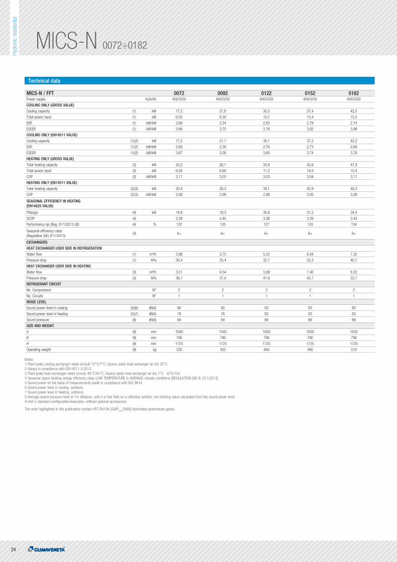
MICS-N 0072÷0182
Modular reversible units, air source for outdoor installation17,3-42,5 kW
MICS-N is the Climaveneta brand range of reversible air-cooled heat pumps featuring axial fans, hermetic scroll compressors and Full Floating technology.
FF Standard version, with built-in hydronic kitFFT Standard version without hydronic kit
Structure and base in hot-dip galvanised steel with epoxy powder paint finish.
Low pressure drop AISI 316 stainless steel plate heat exchangers, fitted with heating element to provide frost protection.
External access to the controller through anti-tamper device.
Finned coils made with copper pipes and aluminium fins with large exchange surface area, tested for leaks with dried air at 30 bar.
User interface with display.
Electronic expansion valve.
Available water pipe fittings.
Differential pressure switch.
Air vent valve.
The hydronic circuit on the FF models includes: - Multistage centrifugal pump - Expansion tank - Safety valve - Pressure gauge - Drain valve.
Keyboard Master ControlMICS features an innovative design that optimises the possibilities of connecting up several units, reducing the necessary access space to a minimum and thereby the overall size of the units.
Increasingly better capacity controlThe possibility of controlling up to six units as a single product means that MICS can increase the number of available control steps, thereby ensuring practically perfect adaptation to the real heat load trend.
Modular designKMC is the central control of the cascade modules. Its main function is to supervise operation of all the modules, making them operate synergically. As a user interface it has a graphic display and a keypad for navigating in the pull-down menus.
Full Floating technologyThe full floating technology with automatic control of the airflow rate, water flow rate and water temperature gains a new function: Flex Energy,used to manage the capacity control steps in linear or alternating sequence in installations with several modules.
Remote control kit
Kit for connecting the KMC keyboard
KMC keyboard for modular system
Coil protection grids
Removable metal mesh water filter kit
Rubber anti-vibration mounting kit
Control Accessories
Features
Version

23
Hydr
onic
resid
entia
l
BA
H
PLATESAXIALSCROLLCOOLINGHEATING
Technical data
MICS-N / FF 0072 0092 0122 0152 0182Power supply V/ph/Hz 400/3/50 400/3/50 400/3/50 400/3/50 400/3/50
COOLING ONLY (GROSS VALUE)
Cooling capacity (1) kW 17,30 21,80 30,3 37,4 42,5
Total power input (1) kW 6,50 9,30 10,7 13,4 15,5
EER (1) kW/kW 2,66 2,34 2,83 2,79 2,74
ESEER (1) kW/kW 3,86 3,75 3,78 3,92 3,96
COOLING ONLY (EN14511 VALUE)
Cooling capacity (1)(2) kW 17,4 21,9 30,4 37,6 42,7
EER (1)(2) kW/kW 2,48 2,26 2,74 2,75 2,68
ESEER (1)(2) kW/kW 3,29 3,40 3,52 3,77 3,75
Cooling energy class E F C C D
HEATING ONLY (GROSS VALUE)
Total heating capacity (3) kW 20,2 26,1 33,9 42,6 47,9
Total power input (3) kW 6,50 8,60 11,2 14,0 15,4
COP (3) kW/kW 3,11 3,03 3,03 3,04 3,11
HEATING ONLY (EN14511 VALUE)
Total heating capacity (3)(2) kW 20,1 26,0 33,8 42,5 47,7
COP (3)(2) kW/kW 2,87 2,88 2,91 2,95 3,01
Cooling energy class C C C C B
SEASONAL EFFICIENCY IN HEATING
(EN14825 VALUE)
PDesign (4) kW 16,6 18,0 30,2 30,7 33,3
SCOP (4) 2,95 3,15 3,09 3,27 3,30
Performance ηs (Reg. 811/2013 UE) (4) % 115 123 120 128 129
Seasonal efficiency class (Regulation (UE) 811/2013)
(4) A A A A+ A+
EXCHANGERS
HEAT EXCHANGER USER SIDE IN REFRIGERATION
Water flow (1) m³/h 2,98 3,75 5,22 6,44 7,32
Available unit's head (1) kPa 133,5 150,2 111,4 132,2 142,7
HEAT EXCHANGER USER SIDE IN HEATING
Water flow (3) m³/h 3,51 4,54 5,89 7,40 8,32
Available unit's head (3) kPa 102,2 122,2 86,7 78,4 118,2
REFRIGERANT CIRCUIT
No. Compressors N° 2 2 2 2 2
No. Circuits N° 1 1 1 1 1
NOISE LEVEL
Sound power level in cooling (5)(6) dB(A) 80 80 83 83 83
Sound power level in heating (5)(7) dB(A) 78 78 83 83 83
Sound pressure (8) dB(A) 64 64 66 66 66
SIZE AND WEIGHT
A (9) mm 1040 1040 1630 1630 1630
B (9) mm 790 790 790 790 790
H (9) mm 1725 1725 1725 1725 1725
Operating weight (9) kg 330 350 440 480 510
Notes:1 Plant (side) cooling exchanger water (in/out) 12°C/7°C; Source (side) heat exchanger air (in) 35°C.2 Values in compliance with EN14511-3:2013.3 Plant (side) heat exchanger water (in/out) 40°C/45°C; Source (side) heat exchanger air (in) 7°C - 87% R.H.4 Seasonal space heating energy efficiency class LOW TEMPERATURE in AVERAGE climate conditions [REGULATION (UE) N. 811/2013]5 Sound power on the basis of measurements made in compliance with ISO 9614.6 Sound power level in cooling, outdoors.7 Sound power level in heating, outdoors.8 Average sound pressure level at 1m distance, unit in a free field on a reflective surface; non-binding value calculated from the sound power level.9 Unit in standard configuration/execution, without optional accessories.
Certified data in EUROVENT
The units highlighted in this publication contain HFC R410A [GWP100
2088] fluorinated greenhouse gases.
24
Hydr
onic
resid
entia
l
MICS-N 0072÷0182
Technical data
MICS-N / FFT 0072 0092 0122 0152 0182Power supply V/ph/Hz 400/3/50 400/3/50 400/3/50 400/3/50 400/3/50
COOLING ONLY (GROSS VALUE)
Cooling capacity (1) kW 17,3 21,8 30,3 37,4 42,5
Total power input (1) kW 6,50 9,30 10,7 13,4 15,5
EER (1) kW/kW 2,66 2,34 2,83 2,79 2,74
ESEER (1) kW/kW 3,86 3,75 3,78 3,92 3,96
COOLING ONLY (EN14511 VALUE)
Cooling capacity (1)(2) kW 17,2 21,7 30,1 37,2 42,2
EER (1)(2) kW/kW 2,60 2,30 2,76 2,73 2,68
ESEER (1)(2) kW/kW 3,67 3,58 3,60 3,74 3,76
HEATING ONLY (GROSS VALUE)
Total heating capacity (3) kW 20,2 26,1 33,9 42,6 47,9
Total power input (3) kW 6,50 8,60 11,2 14,0 15,4
COP (3) kW/kW 3,11 3,03 3,03 3,04 3,11
HEATING ONLY (EN14511 VALUE)
Total heating capacity (2)(3) kW 20,4 26,3 34,1 42,9 48,3
COP (2)(3) kW/kW 3,06 2,99 2,98 3,00 3,06
SEASONAL EFFICIENCY IN HEATING (EN14825 VALUE)
PDesign (4) kW 14,9 18,3 30,6 31,2 34,0
SCOP (4) 3,38 3,45 3,26 3,39 3,43
Performance ηs (Reg. 811/2013 UE) (4) % 132 135 127 133 134
Seasonal efficiency class (Regulation (UE) 811/2013)
(4) A+ A+ A+ A+ A+
EXCHANGERS
HEAT EXCHANGER USER SIDE IN REFRIGERATION
Water flow (1) m³/h 2,98 3,75 5,22 6,44 7,32
Pressure drop (1) kPa 26,4 25,4 32,7 32,3 40,7
HEAT EXCHANGER USER SIDE IN HEATING
Water flow (3) m³/h 3,51 4,54 5,89 7,40 8,32
Pressure drop (3) kPa 36,7 37,0 41,6 42,7 52,7
REFRIGERANT CIRCUIT
No. Compressors N° 2 2 2 2 2
No. Circuits N° 1 1 1 1 1
NOISE LEVEL
Sound power level in cooling (5)(6) dB(A) 80 80 83 83 83
Sound power level in heating (5)(7) dB(A) 78 78 83 83 83
Sound pressure (8) dB(A) 64 64 66 66 66
SIZE AND WEIGHT
A (9) mm 1040 1040 1630 1630 1630
B (9) mm 790 790 790 790 790
H (9) mm 1725 1725 1725 1725 1725
Operating weight (9) kg 330 350 440 480 510
Notes:1 Plant (side) cooling exchanger water (in/out) 12°C/7°C; Source (side) heat exchanger air (in) 35°C.2 Values in compliance with EN14511-3:2013.3 Plant (side) heat exchanger water (in/out) 40°C/45°C; Source (side) heat exchanger air (in) 7°C - 87% R.H.4 Seasonal space heating energy efficiency class LOW TEMPERATURE in AVERAGE climate conditions [REGULATION (UE) N. 811/2013]5 Sound power on the basis of measurements made in compliance with ISO 9614.6 Sound power level in cooling, outdoors.7 Sound power level in heating, outdoors.8 Average sound pressure level at 1m distance, unit in a free field on a reflective surface; non-binding value calculated from the sound power level.9 Unit in standard configuration/execution, without optional accessories.
The units highlighted in this publication contain HFC R410A [GWP100
2088] fluorinated greenhouse gases.

25
Hydr
onic
resid
entia
l
PLATESAXIALSCROLLCOOLINGHEATING
26
Hydr
onic
resid
entia
l
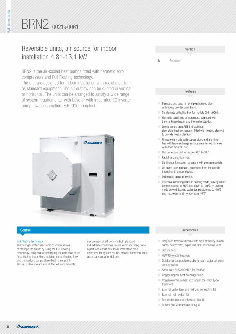
BRN2 0021÷0061
Reversible units, air source for indoorinstallation 4,81-13,1 kW
BRN2 is the air-cooled heat pumps fitted with hermetic scroll compressors and Full Floating technology. The unit are designed for indoor installation with radial plug-fanas standard equipment. The air outflow can be ducted in vertical or horizontal. The units can be arranged to satisfy a wide range of system requirements: with base or with integrated EC inverter pump low consumption, ErP2015 complied.
B Standard
Structure and base in hot-dip galvanised steel with epoxy powder paint finish.
Condensate collecting tray for models 0011÷0061.
Hermetic scroll type compressors, equipped with the crankcase heater and thermal protection.
Low pressure drop AISI 316 stainless steel plate heat exchangers, fitted with heating element to provide frost protection.
Finned coils made with copper pipes and aluminium fins with large exchange surface area, tested for leaks with dried air at 30 bar.
Coil protection grid for models 0011÷0061.
Radial fan, plug-fan type.
Continuous fan speed regulation with pressure switch.
On board user interface, accessible from the outside through anti-tamper device.
Differential pressure switch.
Extensive operating limits in heating mode, leaving water temperature up to 55°C and down to -10°C, in cooling mode as well, leaving water temperature up to -10°C and max external air temperature 46°C.
Full Floating technologyThe new generation electronic controller allows to manage the chiller by using the Full Floating technology, designed for controlling the efficiency of the fans (floating fans), the circulating pump (floating flow) and the working temperature (floating set point). This also allows to achieve all the following benefits:
improvement of efficiency in both standard and extreme conditions, much lower operating noise in part load conditions, lower installation time, lower time for system set-up, broader operating limits, faster transient after defrosts.
Integrated hydronic module with high efficiency inverter pump, safety valve, expansion tank, manual air vent
Soft starters
HSW15 remote keyboard
Outside air temperature probe for plant water set point compensation.
Serial card BUS ADAPTER for ModBus
Copper-Copper heat exchanger coils
Copper-Aluminum heat exchanger coils with epoxy treatment
External buffer tank and hydronic connecting kit
External main switch kit
Removable metal mesh water filter kit
Rubber anti-vibration mounting kit
Control Accessories
Features
Version

27
Hydr
onic
resid
entia
l
PLATESCENTRIFUGALSCROLLCOOLINGHEATING
B
H
A
Technical data
BRN2 0021 0025 0031 0041 0021 0025 0031 0041 0051 0061Power supply V/ph/Hz 230/1/50 230/1/50 230/1/50 230/1/50 400/3/50 400/3/50 400/3/50 400/3/50 400/3/50 400/3/50
PERFORMANCE
COOLING ONLY (GROSS VALUE)
Cooling capacity (1) kW 4,82 5,91 7,31 9,61 4,81 6,01 7,37 10,0 11,2 13,1
Total power input (1) kW 2,19 2,66 3,52 4,3 2,15 2,53 3,24 4,43 4,88 5,42
EER (1) kW/kW 2,20 2,22 2,08 2,23 2,24 2,38 2,27 2,26 2,3 2,42
ESEER (1) kW/kW 2,68 2,69 2,62 2,62 2,68 2,88 2,69 2,67 2,58 2,80
COOLING ONLY (EN14511 VALUE)
Cooling capacity (1)(2) kW 4,81 5,89 7,29 9,56 4,80 5,99 7,35 9,95 11,1 13,0
EER (1)(2) kW/kW 2,45 2,46 2,23 2,51 2,50 2,64 2,46 2,52 2,51 2,63
ESEER (1)(2) kW/kW 3,07 3,05 2,87 3,03 3,09 3,29 2,99 3,09 2,85 3,11
Cooling energy class E E F D D D E D D D
HEATING ONLY (GROSS VALUE)
Total heating capacity (3) kW 6,73 8,33 10,4 12,8 6,70 8,25 10,0 13,3 14,7 17,2
Total power input (3) kW 2,47 3,09 3,71 4,80 2,46 2,94 3,48 4,94 5,08 6,02
COP (3) kW/kW 2,72 2,70 2,80 2,67 2,72 2,81 2,87 2,69 2,89 2,86
HEATING ONLY (EN14511 VALUE)
Total heating capacity (3)(2) kW 6,76 8,37 10,5 12,9 6,73 8,29 10,0 13,4 14,8 17,3
COP (3)(2) kW/kW 3,01 2,95 3,01 2,96 3,01 3,08 3,10 2,99 3,15 3,10
Cooling energy class B C B C B B B C B B
SEASONAL EFFICIENCY IN HEATING (EN14825 VALUE)
PDesign (4) kW 4,88 6,30 7,47 9,84 4,88 6,02 7,14 10,1 10,90 12,6
SCOP (4) 3,09 3,18 3,14 3,10 3,18 3,32 3,17 3,21 3,06 3,14
Performance ηs (Reg. 811/2013 UE) (4) % 120 124 123 121 124 130 124 125 119 123
Seasonal efficiency class (Regulation (UE) 811/2013)
(4) A A+ A A A+ A+ A+ A+ A A
EXCHANGERS
HEAT EXCHANGER USER SIDE IN REFRIGERATION
Water flow (1) m³/h 0,83 1,02 1,26 1,65 0,83 1,03 1,27 1,72 1,93 2,25
Pressure drop (1) kPa 4,82 5,80 6,34 12,6 4,81 5,99 6,44 13,6 14,00 13,7
HEAT EXCHANGER USER SIDE IN HEATING
Water flow (3) m³/h 1,17 1,45 1,81 2,23 1,16 1,43 1,74 2,31 2,56 2,99
Pressure drop (3) kPa 9,58 11,7 13,1 22,9 9,48 11,5 12,1 24,6 24,6 24,1
REFRIGERANT CIRCUIT
No. Compressors N° 1 1 1 1 1 1 1 1 1 1
No. Circuits N° 1 1 1 1 1 1 1 1 1 1
FANS
Air flow m³/s 0,81 0,93 0,93 1,77 0,81 0,93 0,93 1,77 1,61 1,74
Available static pressure Pa 120 120 120 120 120 120 120 120 120 120
NOISE LEVEL
Sound power level in cooling (5)(6) dB(A) 75 75 75 77 65 70 70 70 70 78
Sound power level in heating (5)(7) dB(A) 75 75 75 77 75 75 75 77 77 77
Sound power level in heating (5)(8) dB(A) 65 70 70 70 75 75 75 77 77 77
SIZE AND WEIGHT
A (9) mm 900 900 900 900 900 900 900 900 900 900
B (9) mm 580 580 580 580 580 580 580 580 580 630
H (9) mm 640 940 940 1240 640 940 940 1240 1240 1390
Operating weight (9) kg 115 130 135 180 115 130 135 180 200 210
Notes:1 Plant (side) cooling exchanger water (in/out) 12°C/7°C; Source (side) heat exchanger air (in) 35°C.2 Values in compliance with EN14511-3:2013.3 Plant (side) heat exchanger water (in/out) 40°C/45°C; Source (side) heat exchanger air (in) 7°C - 87% R.H.4 Seasonal space heating energy efficiency class LOW TEMPERATURE in AVERAGE climate conditions [REGULATION (UE) N. 811/2013]5 Total sound power of fans, as declared by the maker, at the rated speed of rotation and a useful static head of 120 Pa on the delivery side.6 Sound power level in cooling, indoors.7 Sound power level in heating, indoors.8 Sound power level in cooling, outdoors.9 Unit in standard configuration/execution, without optional accessories.
Certified data in EUROVENT
The units highlighted in this publication contain HFC R410A [GWP100
2088] fluorinated greenhouse gases.

28
Hydr
onic
resid
entia
l
MICS-CN 0072÷0122
Reversible units, air source for indoorinstallation 17,3-30,3 kW
MICS-CN is the Climaveneta brand range of air-cooled heat pumps featuring hermetic scroll compressors and full floating technology. Thanks to the ducted centrifugal fans, these units can also be installed outdoor.
FF Standard version, with built-in hydronic kit
Structure and base in hot-dip galvanised steel with epoxy powder paint finish.
Low pressure drop AISI 316 stainless steel plate heat exchangers, fitted with heating element to provide frost protection.
Control with anti-tamper device accessible from the outside.
Finned coils made with copper pipes and aluminium fins with large exchange surface area, tested for leaks with dried air at 30 bar.
User interface with display.
Electronic expansion valve.
Available water pipe fittings.
The circuit includes: - Multistage centrifugal pump - Air vent valve - Differential pressure switch. - Expansion tank - Safety valve - Pressure gauge - Drain valve.
The full range is also available with the Class A efficiency rating (in heating).
Full Floating technologyThe new generation electronic controller allows to manage the chiller by using the Full Floating technology, designed for controlling the efficiency of the fans (floating fans), the circulating pump (floating flow) and the working temperature (floating set point).
This also allows to achieve all the following benefits: improvement of efficiency in both standard and extreme conditions, much lower operating noise in part load conditions, lower installation time, lower time for system set-up, broader operating limits, faster transient after defrosts.
Rubber anti-vibration mounting kit
Removable metal mesh water filter kit
Coil protection grids
Remote control kit
Control Accessories
Features
Version

29
Hydr
onic
resid
entia
l
ENERGY CLASSPLATESCENTRIFUGALSCROLLCOOLINGHEATING
Technical data
MICS-CN / FF 0072 0092 0122Power supply V/ph/Hz 400/3/50 400/3/50 400/3/50
PERFORMANCE
COOLING ONLY (GROSS VALUE)
Cooling capacity (1) kW 17,3 21,8 30,3
Total power input (1) kW 6,50 9,30 10,7
EER (1) kW/kW 2,66 2,34 2,83
ESEER (1) kW/kW 3,86 3,75 3,78
COOLING ONLY (EN14511 VALUE)
Cooling capacity (1)(2) kW 17,4 21,9 30,4
EER (1)(2) kW/kW 2,77 2,44 3,16
ESEER (1)(2) kW/kW 4,27 4,09 4,80
Cooling energy class A C A
HEATING ONLY (GROSS VALUE)
Total heating capacity (3) kW 20,2 26,1 33,9
Total power input (3) kW 6,50 8,60 11,2
COP (3) kW/kW 3,11 3,03 3,03
HEATING ONLY (EN14511 VALUE)
Total heating capacity (3)(2) kW 20,1 26,0 33,8
COP (3)(2) kW/kW 3,20 3,14 3,32
Cooling energy class A A A
SEASONAL EFFICIENCY IN HEATING (EN14825 VALUE)
PDesign (4) kW 14,6 18,0 24,8
SCOP (4) 3,27 3,36 3,60
Performance ηs (Reg. 811/2013 UE) (4) % 128 132 141
Seasonal efficiency class (Regulation (UE) 811/2013)
(4) A+ A+ A+
EXCHANGERS
HEAT EXCHANGER USER SIDE IN REFRIGERATION
Water flow (1) m³/h 2,98 3,75 5,22
Available unit's head (1) kPa 133,5 150,2 111,4
HEAT EXCHANGER USER SIDE IN HEATING
Water flow (3) m³/h 3,51 4,54 5,89
Available unit's head (3) kPa 102,2 122,2 86,7
REFRIGERANT CIRCUIT
No. Compressors N° 2 2 2
No. Circuits N° 1 1 1
FANS
Air flow m³/s 2,50 2,50 5,00
Available static pressure Pa 120 120 120
NOISE LEVEL
Sound power level in cooling (5)(6) dB(A) 86 86 89
Sound power level in heating (5)(7) dB(A) 86 86 89
Sound power level in heating (5)(8) dB(A) 78 78 78
SIZE AND WEIGHT
A (9) mm 1040 1040 1630
B (9) mm 790 790 790
H (9) mm 2000 2000 2000
Operating weight (9) kg 350 370 480
Notes:1 Plant (side) cooling exchanger water (in/out) 12°C/7°C; Source (side) heat exchanger air (in) 35°C.2 Values in compliance with EN14511-3:2013.3 Plant (side) heat exchanger water (in/out) 40°C/45°C; Source (side) heat exchanger air (in) 7°C - 87% R.H.4 Seasonal space heating energy efficiency class LOW TEMPERATURE in AVERAGE climate conditions [REGULATION (UE) N. 811/2013]5 Total sound power of fans, as declared by the maker, at the rated speed of rotation and a useful static head of 120 Pa on the delivery side.6 Sound power level in cooling, indoors.7 Sound power level in heating, indoors.8 Sound power level in heating, outdoors.9 Unit in standard configuration/execution, without optional accessories.
Certified data in EUROVENT
The units highlighted in this publication contain HFC R410A [GWP100
2088] fluorinated greenhouse gases.
A
H
B

30
Hydr
onic
resid
entia
l
BRAT-MC 0011÷0121
Refrigeratori e pompe di calore per il residenziale
Condensing units5,61-33,4 kW
Outdoor split-system units to be connected with direct expansion coils or remote exchangers. BRAT-MC units are equipped with hermetic rotary scroll compressor and axial-flow fans. External panels and basement are in galvanised sheet steel with paint finish.
B StandardSL Super-low noise version
Coil protection grid for models 0011÷0061.
Structure and base in hot-dip galvanised steel with epoxy powder paint finish.
Control with anti-tamper device accessible from the outside.
Finned coils made with copper pipes and aluminium fins with large exchange surface area, tested for leaks with dried air at 30 bar.
User interface with display.
Phase sequence controller for models 0071÷0121.
HSW15 Electronic ControllerThe HSW15 device is the new controller for the management of condensing units. The new 4-digit display offers clear reading of the variables, while the 14 symbols give an immediate view of machine status for system diagnostics. The 4 keys can be used to navigate the tree menu, password-protected for maximum security.The electronic controller incorporates a series of protection algorithms in order to prevent damage being done to the main system components.
The most important algorithm includes parameters concerning compressor start-up times in order to prevent over-frequent starting times (minimum delay after last stop and minimum delay after last start). Condensation control is managed by modulating the air flow through the condensation coils, thus by varying the ventilation speed. This system rapidly increases the unit’s efficiency and the environmental comfort.
Control
Rubber anti-vibration mounting kit
Coil protection grid for models 0071÷0121
External main switch kit
HSW10 remote keyboard
Accessories
Features
Version

31
Hydr
onic
resid
entia
l
AXIALSCROLLCOOLING
A B
H
Technical data
BRAT-MC / B 0011 0021 0025 0031 0041 0021 0025 0031Power supply V/ph/Hz 230/1/50 230/1/50 230/1/50 230/1/50 230/1/50 400/3/50 400/3/50 400/3/50
PERFORMANCE
COOLING
Cooling capacity (1) kW 5,61 6,69 7,51 9,60 12,70 6,09 7,49 9,30
Total power input (1) kW 1,87 2,18 2,48 3,34 4,15 2,09 2,39 3,25
EER (1) kW/kW 3,00 3,07 3,03 2,87 3,06 2,91 3,13 2,86
REFRIGERANT CIRCUIT
No. Compressors N° 1 1 1 1 1 1 1 1
No. Circuits N° 1 1 1 1 1 1 1 1
NOISE LEVEL
Sound pressure (2) dB(A) 34 35 35 35 38 35 35 35
Sound power level in cooling (3)(4) dB(A) 65 66 66 66 69 66 66 66
SIZE AND WEIGHT
A 900 900 900 900 900 900 900 900
B (5) mm 370 370 370 370 370 370 370 370
H (5) mm 640 640 940 940 1240 640 940 940
Operating weight (5) kg 80 85 100 105 125 85 100 105
BRAT-MC / B 0041 0051 0061 0071 0091 0101 0121Power supply V/ph/Hz 400/3/50 400/3/50 400/3/50 400/3/50 400/3/50 400/3/50 400/3/50
PERFORMANCE
COOLING
Cooling capacity (1) kW 12,7 14,3 16,6 20,1 22,7 27,8 33,4
Total power input (1) kW 4,25 4,67 5,32 6,90 8,02 8,86 11,8
EER (1) kW/kW 2,99 3,06 3,12 2,91 2,83 3,14 2,83
REFRIGERANT CIRCUIT
No. Compressors N° 1 1 1 1 1 1 1
No. Circuits N° 1 1 1 1 1 1 1
NOISE LEVEL
Sound pressure (2) dB(A) 38 38 38 43 43 44 44
Sound power level in cooling (3)(4) dB(A) 69 69 69 74 74 76 76
SIZE AND WEIGHT
A 900 900 900 1450 1450 1450 1450
B (5) mm 370 370 420 550 550 550 550
H (5) mm 1240 1240 1390 1200 1200 1700 1700
Operating weight (5) kg 125 145 155 245 250 320 325
Notes:1 Saturated intake temperature (dew) 5 °C; Source (side) heat exchanger air (in) 35 °C.2 Average sound pressure level at 10 (m.) distance, unit in a free field on a reflective surface; non-binding value calculated from the sound power level.3 Sound power on the basis of measurements made in compliance with ISO 9614.4 Sound power level in cooling, outdoors.5 Unit in standard configuration/execution, without optional accessories.
The units highlighted in this publication contain HFC R410A [GWP100
2088] fluorinated greenhouse gases.
Head Of�ce: Via Sarson 57/c - 36061 Bassano del Grappa (VI) - ItalyTel (+39) 0424 509 500 - Fax (+39) 0424 509 509
www.climaveneta.comwww.melcohit.com
RESI
DENT
IAL
CHIL
LERS
_01-
2017
_ENG