i electricalpartmanuals . com · circuit breaker timing ..... ..... 20 ... contact travel...
TRANSCRIPT

- SfEM·ENS I I II I II I I I I I II I I I I II " I
•'·
Installation • Operation • Maintenance
Instructions
SDV-25 Power Circuit Breaker PB 3758-Q1
_..._. _____________ ·-- · · --···
www . El
ectric
alPar
tMan
uals
. com

• • • • II • •
•
•
CoNTENTS
TABLE OF CONTENTS
G
eneral Introduction . . . . . . . . . . . . . . . . . . . . . . . . . . . . . . . . . 1 Qualified Person . . . . . . . . . . . . . . . . . . . . . . . . . . . . . 1 Description . . . . . . . . . . . . . . . . . . . . . . . . . . . . . . . . . . 2 Receiving . . . . . . . . . . . . . . . . . . . . . . . . . . . . . . . . . . . 2 Storage . . . . . . . . . . . . . . . . . . . . . . . . . . . . . . . . . . . . . 2
Technical Data Dielectric Data . . . . . . . . . . . . . . . . . . . . . . . . . . . . . . . 3 Electrical Data . . . . . . . . . . . . . . . . . . . . . . . . . . . . . . . 3 Mechanical Data . . . . . . . . . . . . . . . . . . . . . . . . . . . . . 4 Control Data . . . . . . . . . . . . . . . . . . . . . . . . . . . . . . . . . 4 Arc-Quenching Medium . . . . . . . . . . . . . . . . . . . . . . . . 5
Description General . . . . . . . . . . . . . . . . . . . . . . . . . . . . . . . . . . . . . 6 High Voltage . . . . . . . . . . . . . . . . . . . . . . . . . . . . . . . . . 6 Control and Relay Compartment . . . . . . . . . . . . . . . . . 6 Interrupting Unit . . . . . . . . . . . . . . . . . . . . . . . . . . . . . . 8 Switching Operation . . . . . . . . . . . . . . . . . . . . . . . . . . 9 Operating Mechanism . . . . . . . . . . . . . . . . . . . . . . . . . 1 0 Opening . . . . . . . . . . . . . . . . . . . . . . . . . . . . . . . . . . . . 1 0 Closing . . . . . . . . . . . . . . . . . . . . . . . . . . . . . . . . . . . . . 1 0 Charging . . . . . . . . . . . . . . . . . . . . . . . . . . . . . . . . . . . . 1 2
Installation Shipment and Storage . . . . . . . . . . . . . . . . . . . . . . . . . 1 3 Location . . . . . . . . . . . . . . . . . . . . . . . . . . . . . . . . . . . . 1 3 Primary Lead Connections . . . . . . . . . . . . . . . . . . . . . 1 3 Ground Connection . . . . . . . . . . . . . . . . . . . . . . . . . . . 1 3 Secondary and Control Wiring . . . . . . . . . . . . . . . . . . . 1 3 Final Installing Inspection . . . . . . . . . . . . . . . . . . . . . . 1 3
Electrical Control Typical Schematic . . . . . . . . . . . . . . . . . . . . . . . . . . .. 16 Spring Charging . . . . . . . . . . . . . . . . . . . . . . . . . . . . . . 17 Closing . . . . . . . . . . . . . . . . . . . . . . . . . . . . . . . . . . . . . 17 Tripping . . . . . . . . . . . . . . . . . . . . . . . . . . . . . . . . . . . . 17 Reclosing . . . . . . . . . . . . . . . . . . . . . . . . .. . . . . . . . . . 17 Complete Closing Sequence . . . . . . . . . . . . . . . . . . . . 18 Complete Tripping Sequence . . . . . . . . . . . . . . . . . . . 1 9 Complete Anti-Pump Sequence . . . . . . . . . . . . . . . . . . 1 9
Adjustments General . . . . . . . . . . . . . . . . . .. . . . . . . . . . . . . . . . . . . 20 Circuit Breaker Timing . . . . . . . . . . . . . . . . . . . . . .. . . 20 Auxiliary Switch . . . . . . . . . . . . . . . . . . . . . . . . . . . . . . 20 Trip Latch Adjustment . . . . . . . . . . . . . . . . . . . . . . . . . 21 Close Latch Adjustment . . . . . . . . . . . . . . . . . . . . . . . 21 Motor Cut-Off and Anti-Pump Control Switch . . . . . . . 21 Vacuum Interrupter Stroke Adjustment . . . . . . . . . . . . 21 Contact Pressure Spring Stroke . . . . . . . . . . . . . . . . . . . 22 Contact Erosion Adjustment . . . . . . . . . . . . . . . . . . . . . . 2 3
Maintenance General . . . . . . . . . . . . . . . . . . . . . . . . . . . . . . . . . . . . . 2 4 Inspection Schedule . . . . . . . . . . . . . . . . . . . . . . . . . . . 2 4 Contact Erosion . . . . . . . . . . . . . . . . . . . . . . . . . . . . . . 2 4 Interrupter Vacuum . . . . . . . . . . . . . . . . . . . . . . . . . . . 2 4 Hydraulic Shock Absorber . . . . . . . . . . . . . . . . . . . . . . 2 4 Interrupter Replacement . . . . . . . . . . . . . . . . . . . . . . . 2 5 Re-lubricating . . . . . . . . . . . . . . . . . . . . . . . . . . . . . . . . 27 Special Tools . . . . . . . . . . . . . . . . . . . . . . . . . . . . . . . . 27 Replacement Parts . . . . . . . . . . . . . . . . . . . . . . . . . . . . 27 Bushing & Stand-Off Insulators . . . . . . . . . . . . . . . . . . 2 8 Bushing Current Transformers . . . . . . . . . . . . . . . . . . 2 8 Relay Panel . . . . . . . . . . . . . . . . . . . . . . . . . . . . . . . . . . 2 9
The instructions contained within this manual are necessary tor the sate installation, maintenance and operation of this equipment. It this manual is misplaced or lost, replacement manuals are available through the local Siemens sales office.
These instructions do not purport to cover all details or variations in equipment, nor to provide tor every possible contingency to be met in connection with installation, operation or maintenance. Should further information be desired or should particular problems arise which are not covered sufficiently for the purchaser's purposes, the matter should be referred to the local Siemens sales office.
The contents of this instruction manual shall not become part of or modify any prior or existing agreement, commitment or relationship. The sales contract contains the entire obligation of Siemens. The warranty contained in the contract between the parties is the sole warranty of Siemens. Any statements contained herein do not create new warranties or modify the existing warranty.
If drawings or other supplementary instructions for specific applications are forwarded with the manual or separately, they take precedence over any conflicting or incomplete information in this manual.
www . El
ectric
alPar
tMan
uals
. com

.--------------------------------------------------------------------------�-----------
CONTENTS
ILLUSTRATIONS
Figure 1 Figure 2 Figure 3 Figure 4 Figure Sa Figure Sb Figure 6 Figure 7 Figure 8 Figure 9 Figure 10 rigure 11 Figure 12 Figure 13 Figure 14 Figure 15 Figure 16 Figure 17 Figure 18 Figure 19 Figure 20 Figure 21 Figure 22 Figure 2 3 Figure 2 4
Lifting Vacuum Breaker . . . . . . . . . . . . . . . . . . . . . . . . . . . . . . . . . . . . . . . . . . . . . . . . . . . . . . . . . . . . . . . . . 2 Section throuoh A Vacuum Interrupter . . . . . . . . . . . . . . . . . . . . . . . . . . . . . . . . . . . . . . . . . . . . . . . . . . . . . 5 SDV-2 5 Circuit Breaker . . . . . . . . . . . . . . . . . . . . . . . . . . . . . . . . . . . . . . . . . . . . . . . . . . . . . • . . . . . . . • . . . . • . . . • • . 7 Section through the 3AF Interrupting Unit . . . . . . . . . . . . . . . . . . . . . . . . . . . . . . . . . . . . . . . . . . . . . . . . . . . 8 Section through the 3AF Breaker in the Open Position . . . . . . . . . . . . . . . . . . . . . . . . . . . . . . . . . . . . . . . . . 9 Section through the 3AF Breaker in the Closed Position . . . . . . . . . . . . . . . . . . . . . . . . . . . . . . . . . . . . . . . 9 3AF in the Closed Position With the Closing and Tripping Springs Charged . . . . . . . . . . . . . . . . . . . . . . . . 10 3AF in the Closed Position (Tripping Spring Charged and Latched) . . . . . . . . . . . . . . . . . . . . . . . . . . . . . . . 11
Breaker Shaft in the Open Position . . . . . . . . . . . . . . . . . . . . . . . . . . . . . . . . . . . . . . . . . . . . . . . . . . . . . . . . 11 Closing Assembly With Slack Closing Spring . . . . . . . . . . . . . . . . . . . . . . . . . . . . . . . . . . . . . . . . . . . . . . . . 12 Lower Pole Support With Insulated Coupler ................................................. 15 Procedure to Check Vacuum . . . . . . . . . . . . . . . . . . . . . . . . . . . . . . . . . . . . . . . . . . . . . . . . . . . . . . . . . . . . . 15 Procedure to Check Vacuum . . . . . . . . . . . . . . . . . . . . . . . . . . . . . . . . . . . . . . . . . . . . . . . . . . . . . . . . . . . . . 15 Control Scheme for 3AF Operator ......................................................... 16 Complete Closing Sequence . . . . . . . . . . . . . . . . . . . . . . . . . . . . . . . . . . . . . . . . . . . . . . . . . . . . . . . . . . . . . 18 Complete Tripping Sequence . . . . . . . . . . . . . . . . . . . . . . . . . . . . . . . . . . . . . . . . . . . . . . . . . . . . . . . . . . . . . 19 Complete Anti-Pump Sequence . . . . . . . . . . . . . . . . . . . . . . . . . . . . . . . . . . . . . . . . . . . . . . . . . . . • . . . . . . . 19 Type Q-10 Auxiliary Switch . . . . . . . . . . . . . . . . . . . . . . . . . . . . . . . . . . . . . . . . . . . . . . . . . . . . . . . . . . . . . . . 20 Location of Trip Latch Adjustment Screw .................................... .............. . 21 Closing Latch Measurement . . . . . . . . . . . . . . . . . . . . . . . . . . . . . . . . . . . . . . . . . . . . . . . . . . . . . . . . . . . . . 21 Contact Travel Measurement . . . . . . . . . . . . . . . . . . . . . . . . . . . . . . . . . . . . . . . . . . . . . . . . . . . . . . . . . . . . . 22 Contact Pressure Spring Measurement . . . . . . . . . . . . . . . .. . . . . . . . . . . . . . . . . . . . . . . . . . . . . . . . . . . . 22 Contact Erosion Check . . . . . . . . . . . . . . . . . . . . . . . . . . . . . . . . . . . . . . . . . . . . . . . . . . . . . . . . . . . . . . . . . 2 3 Procedure to Tighten Terminal Clamp . . . . . . . . . . . . . . . . . . . . . . . . . . . . . . . . . . . . . . . . . . . . . . . . . . . . . . 26 Points to be Lubricated . . . . . . . . . . . . . . . . . . . . . . . . . . . . . . . . . . . . . . . . . . . . . . . . . . . . . . . . . . . . . . . . . 2 7
www . El
ectric
alPar
tMan
uals
. com

• • • •
•
Ill
II
GENERAL
DIMENSIONS
Throughout this manual, metric values, when used, are shown as (XXX).
INTRO DUCTION
Siemens outdoor circuit breakers are precision built devices designed to function efficiently under normal operating conditions. They are designed and manufactured to operate within the ANSI C37 standards applicable to the breaker rating.
The successful field performance of these breakers depends as much on proper installation and maintenance as it does on good design and careful manufacture. Refer to these sections before performing any installation or maintenance.
Factory adjustments are carefu lly made and the breaker is given rigorou s m echanical tests after which the adjustments are re-checked. All control wiring is given a 15 0 0 volt AC 1 minute withstand test. The c urrent transformers are manufactured and tested according to the ANSI C57.13 standards.
The instructions included in this book are necessary for safe installation, maintenance and operation and to aid you in obtaining longer and more economical service from your Siemens circuit breakers. For proper installation and operation - resulting in better service and lower maintenance costs - this information should be distributed to your operators and engineers.
By carefu lly following these instructions, difficu lties shou ld be avoided. However, they are not intended to cover all details or variations that may be encountered in c onnection with the installation, operation and maintenance of this equ ipment.
Should additional information be desired, including rep lac ement instruction books, contact your Siemens representative.
Distinctive signal words (DANGER, WARNING, CAUTION) are u sed in this instruction book to indicate degrees of
Page1
hazard that may be encountered by the user. For the purpose of this manual and product labels these signal words are defined below.
DANGER Indicates death, severe personal injury or substantial property damage will result if proper precautions are not taken.
WARNING Indicates death, severe personal injury or substantial property damage can result if proper precautions are not taken.
CAUTION indicates minor personal injury or property damage can resu lt if proper precautions are not taken.
A DANGER
Hazardou s voltage and mechanisms. S evere personal injury due to electrical shock, burns and entanglement in moving parts or property damage will result if safety instructions are not followed.
Do not service or touch u ntil you have de-energized high voltage, grounded all terminals and turned off control voltage.
O nly q ualified personnel should work on or around this equipment after becoming thoroughly familiar with all warn-ings, safety notices, instructions and maintenance procedures contained herein. The su ccessfu l and safe operation of this equ ipment is dependent u pon proper handling, installation, operation and maintenance.
QUALI FlE D PERSON
For the purpose of this manual, a qualified person is one who is familiar with the instal lation, construction and operation of the equipment, and the hazards involved. In addition, he has the fol lowing qualifications:
a) Is trained and authorized to energize, de-energize, clear, ground, and tag circuits and equipment in accordance with established safety practices.
www . El
ectric
alPar
tMan
uals
. com

GENERAL Page2
b) is trained in the proper care and use of protective equipment such as rubber gloves, hard hat, safety glasses or face shields, flash clothing, etc., in accordance with established safety practices.
c) is trained in rendering first aid.
DESCRIPTION
The type SDV-25 circuit breaker is a three phase distribution type outdoor u nit for service on systems at 25. 8kV maximum voltage. The breaker is equipped with a trip-free stored energy operating mechanism and one vacuum interrupter per phase. This breaker offers dependable overload protection to connected equipment and lines. It should be installed only in circuits where it will operate within the range given on the breaker nameplate.
The physical arrangement of the circuit breaker comprises a high voltage compartment, an operator compartment, a relay and control power compartment and adjustable legs.
Current transformers are usually furnished with the circuit breaker. The standard breaker includes three current transformers, however, two standard type transformers can be supplied per bushing for a total of twelve transformers per breaker.
RECEIVING
The type SDV-25 circuit breaker is transported from the factory completely assembled and tested, and is carefully inspected and packed . The breaker is shipped with the contacts open, and both the closing spring andtripping springs are discharged.
Immediately upon receipt of a breaker, an examination should be made for evidence of any damage that may have occurred during shipment. If any damage or indication of rough handling is evident, immediately file a damage claim with the transportation company and notify the nearest
Siemens representative.
NOTE Damage claims must be processed within the time period specified by the carrier. Siemens cannot be held responsible for shipping damage, either external or internal, if the inspection is not made and claim forwarded within the set time limit.
Check the vacuum breaker against the shipping list and keep all identification tags and the instruction book so they are available. A pocket has been provided inside the control
power compartment door that contains the instructior' book and the schematic and connection diagrams. Retain all records and identification data since this must accom
pany any later inquiry concerning the breaker.
Unload breaker by use of sling and lifting lugs or with forklift when breaker is shipped on skid. Lifting lugs are provided on each side of the breaker so that the unit may be lifted by use of a sling and hooks of the proper size. (Refer to the breaker nameplate for weight.)
See Figure 1 for lifting of breaker with sling.
Recommended
S
ling Lengt
h
Is 601nc
h
es
Figure 1. Lifting Vacuum Breaker
STORAGE
It the breaker is not to be connected in service immediately, it should be set on an adequate foundation, such as the permanent foundation, and the internal parts kept dry with the compartment heaters or other space heaters that will maintain the inside temperature of the breaker over the ambient. Prolonged outdoor storage without heaters could result in corrosion of internal parts. In any event, It is recommended that the bre;lker receive periodic inspection during storage.
l I I I I I I I I I
www . El
ectric
alPar
tMan
uals
. com

• • •
TECHNICAL DATA
DIELECTRIC DATA
The SDV-25 is a three-pole circuit breaker of outdoor design and uses the arc extinguishing ability of a vacuum to interrupt an arc.
·
The values of insulation level compiled in table 2 are referred to sea level in accordance with ANSI C3 7. 0 4-1 9 7 9 consolidated standards. The higher the site altitude, the lower the insulating capacity of the air. The decrease in insulating capacity is neglected by standards for altitudes of up to 1000m above sea level. For higher altitudes, the values of power-frequency withstand voltage, lightning impulse withstand voltage and rated continuous current must be corrected in accordance with table 1 .
Table 1 Altitude Correction Factors, k
Altitude Rated Maximum Rated Voltage and Continuous
ft (m) Insulation Level Current
330 0 (1 0 0 0) 1 . 0 0 1 .0 0 5 0 0 0 (1 5 0 0) 0. 95 0.9 9
1 0 0 0 0 (30 0 0) 0. 80 0. 96
NOTE: Interpolated correction factors shall be used in determin
ing factors for intermediate altitudes.
ELECTRICAL DATA
Rated max. voltage kV
Rated frequency H z Rated continuous current A Rated short-circuit current kA Transient recovery voltage under -
terminal fault conditions Rated making current kA Rated duration of short-circuit s Rated duty cycle
Page3
Withstand test voltages apply to altitudes up to 1 000 m above sea level. If a breaker is to be instal led at a higher altitude, the appropriate test voltage and continuous current rating must be applied by a correction factor k (Table 1 ).
Rated Voltage
Table 2 Dielectric Ratings
Rated power frequency withstand voltage (kV rms) at 60 Hz
Rated lightning withstand voltage (1.2/SOJLS)
Chopped wave 21's � Breaker In Closed
Chopped wave 31's Post ion Only
kV
kV
kV m ax.
kV kV
Normal Temperature Range
-30 . . . +40 Degrees C -4 0 . . . +4 0 (Special)
25.8
60 See Nameplate See Nameplate
As Per ANSI
25.8
6 0
1 5 0
1 94 1 72
1 .6 x Rated short-circuit breaking current 3
0-0.3S-C0-1 5S-C0-1 5S-C0-15S-CO
www . El
ectric
alPar
tMan
uals
. com

Page4
MECHANICAL DATA
Operating Times Interrupter Units
Minimum command duration cycles 3 Number per pole 1 Closing time cycles 5.0 Travel of contact in. .62 Opening time cycles 1.9 Clearance between open contacts in. .62 Arcing time at 60 Hz cycles 1 Interrupting time at 60 Hz cycles 3 Breaker Weig
h
ts
Breaker, complete without 1bs(kg) 1600(725) relay package
CONTROL DATA
Tripping and Closing Coils
Rated voltage V d.c.CD Tripping coil A Closing coil A
CD Voltage Range 1s m accordance w1th ANSI.
Type Maximum rated voltage Rated normal current Making current Breaking Capacity
Rated voltage V d.c.CD Continuous current A Charging time Sec
CD Voltage Range IS m accordance w1th ANSI
Heaters Operating mechanism compartment Control and relay compartment Low temperature (Special -40° C)
0 Thermostat controlled and set to turn off at 95" F 0 Thermostat controlled and set to turn on at 0" F
w w w
48 125 250 V a.c. CD 115 230 8.2 5.4 2.0 A 5. 0 1.9 2.0 1.0 .5 A .9 .4
Auxiliary
S
witc
h
-
48 6.0
10.0
200(!) 100 5400
3SV9Z V d.c. 500 A 1 0 A 30
Ohmic Load a.c. or d .c. 2200W Ind. Load at 220V d.c. 200W
Motor
125 250 V a.c.CD 115 230 2.5 1.5 A 4.5 2.5 7.8 8.0 Sec 8.3 8.6
TERMINALS
Permissable conductor tension per connecting joint applied in any direction static + dynamic 100 LBS
a
I I I I I I I I I I I ' I I www .
Elec
tricalP
artM
anua
ls . c
om

' ' •
l(
n�· !4.
' I ..
TECHNIGALDATA
ARC-QUENCHING ME DIUM
VACUUM
Vacuum Interrupter
The basic construction of the interrupter can be seen from Figure 2. The moving contact 36 moves in guide 35. The metal bellows 34 follows the travel of the moving contact and seals the interrupter against the surrounding atmosphere.
.1.----- 31.2 ���-31.1
33.
34. ---4-�:---g 35.----�
3 1. Fixed Contact 3 1. 1 Washer 3 1.2 Terminal Post 32. Insulator 33. Arcing Chamber
+-----36.1 "rn�----36.2
34. Metal Bellows 35. Guide 36. Moving Contact 36. 1 Terminal 36.2 Mechanical Coupling
1 Figure 2. Section through a Vacuum Interrupter
Page5
The Arc-quenching Principle
When the contacts separate, the current to be interrupted initiates a metal vapor arc discharge and flows through this plasma until the next current zero. The arc is then extinguished and the conductive metal vapor condenses on the metal surfaces within a matter of microseconds. As a result, the dielectric strength in the break builds up very rapidly.
The contacts are designed so that the self-generated field causes the arc to travel. This prevents localized overheating when interrupting large currents .
The metal vapor arc discharge can only be maintained if a certain minimum current flows. A current that does not attain this level is chopped prior to current zero. This chopping current must be kept to a minimum in order to prevent unduly high overvoltages building up when inductive circuits are switched. The use of a special contact material ensures that current chopping is limited to 4-5A.
The rapid build-up of the dielectric strength in the break enables the arc to be safely extinguished even if contact separation occurs immediately prior to current zero.
The arc drawn in the vacuum breaker is not cooled. The metal vapor plasma is highly conductive and the resulting arc voltage only attains values between 20-200V. For this reason and because of the short arcing times, the arc energy developed in the break is very small. This also accounts for the long electrical life expectancy of the vacuum interrupter.
Owing to the high vacuum (less than 10·9 bar) in the interrupter, contact clearances of only about 6 to 20 mm are needed in order to attain a high dielectric strength .
www . El
ectric
alPar
tMan
uals
. com

DESCRIPTION
Page6
GENERAL
A SDV-25 circuit breaker, rated 25.8kv is shown in Figure 3 . The breaker consists of three main sections: the high voltage compartment, the control and relay compartment, and adjustable legs.
HIGH VOLTAGE COMPARTMENT
The high voltage compartment supports six entrance bushings, and encloses the bushing current transformers, three vacuum interrupters supported by six stand-off insulators, current carrying bus bars and various current connections and operating linkage assemblies. It consists of a corrosion resistant water tight enclosure with isolating phase barriers between phases and a dead front to the operating compartment and the control and relay compartment. The bushing mounting surface is sloped to provide for positive run-off water. Moisture control is provided by means of air flow and heaters. Each of the interrupters is operated through its own push rod assembly from the main operating shaft in the control compartment. Removable hinged doors are provided for ease in accessibility and maintenance.
A wARNING
Hazardous voltage. Can cause personal InJury, death or damage to the circuit breaker.
Do not open high voltage compartment until you have de-energized the high voltage, grounded all terminals and turned off control power.
A CAUTION
Hazardous radiation.
�.� Can cause personal injury.
To eliminate this hazard the low fre-A quency withstand test must be per-
formed with all covers on and doors closed.
CONTROL AN D RELAY
COMPARTMENT
The control and relay compartment consists of a separate weather-proof compartment isolated from the high voltage compartment by a dead front barrier. It contains the termination terminals for the bushing current transformers, control power cut-off devices and customer wiring terminals. It also contains a swing out relay panel when required. The stored energy operator is also contained within the control compartment.
The breaker is equipped with two adjustable legs attached to the breaker cabinet at each side and serve to mount the breaker to the foundation. The legs are adjustable in 6" increments.
l f I I I I I
' I I ' f I ' ,
www . El
ectric
alPar
tMan
uals
. com

• f· ' II. ---Iii -;I, -rf -II ( -il • •
DESCRIPTI0N
' •D
I
HIGH VOLTAGE COMPARTMENT
�- CONTROL AND OPERATOR COMPARTMENT
Figure 3. SDV-25 Circuit Breaker Rated 25.8kV
' 'j ,. ' ·._, ' ' . Page7
www . El
ectric
alPar
tMan
uals
. com

DESCRIPTION
PageS
INTERRUPTING UNIT
Figure 4 shows a section through an interrupter unit. The vacuum interrupter 30 is rigidly fixed to the upper terminal 27 and pole support 20 by its fixed terminal post 31.2. The lower ceramic part of the interrupter is stabilized against lateral forces by a centering ring 28.1 on pole support 40. The external forces due to switching operations and the contact pressure are absorbed by the braces 28.
40.
29.2 28.1 28. 27
The current flows from the upper terminal 27 through the fixed contact terminal washer(Figure 2 items 31.1) the fixed contact (Figure 2 item 31) the movable contact (Figure 2 item 36) the movable contact terminal post (Figure 2 item 36.1), which is connected with the lower terminal 29 by terminal clamp 29.2, and·ftexible strap 29.1.
The vacuum interru·pter'becomes open by the movable contact (Figure 2 item 36) moving in guide (Figure 2 item 35). The metal bellows (Figure 2 item 34) follows the travel of the moving contact and seals the interrupter against the surrounding atmosphere.
29. 29.1 30. 28. 29.2 28.1
27.
16.2 -+------i,.Y,.....��
48.
16.1 16.2 20. 27. 27.1
Upper Insulator Lower Insulator Upper Pole Support Upper Terminal Terminal Angle
I.S:!f'--- 16.1
60.
28. Brace
48.-+-----ir1\
80.
28.1 Centering Ring 29. Lower Terminal 29.1 Flexible Strap 29.2 Terminal Clamp
30. 31.2 40. 48. 60.
Figure 4. Section through the 3AF Interrupting Unit
Vacuum Interrupter Terminal Post Lower Pole Support Insulated Coupler Mechanism Housing
1 I I I I I I I I I I I I I I I I I www .
Elec
tricalP
artM
anua
ls . c
om

I f f
1
( (
( t I
DESCRIPTION
SWITCHING OPERATION
When a closing command is initiated the closing spring, which was previously charged by hand or by the motor, actuates the moving contact 36 through breaker shaft 63, lever 63.7, insulated coupler 48 and lever 48.6.
The forces that may occur when the action of the insulated coupler is converted into the vertical action of the moving contact are absorbed by drive link 48.9 which pivots on pole support 40 and adapter 36.3.
During closing, the tripping spring and the contact pressure spring 49 are charged and latched by pawl 64.2.
31 . Fixed Contact 36. Moving Contact 36.3 Adapter 40. Lower Pole Support 48. Insulated Coupler
Figure Sa. Section through the 3AF Breaker in the Open Position.
Page9
The closing spring is recharged by the motor immediately after closing.
In the closed state, the necessary contact pressure is established by the contact pressure spring and the atmospheric pressure. The contact pressure spring automatically compensates for the arc erosion, which is very small.
When a tripping command is given, the energy stored in the tripping and contact pressure springs is released by pawl 64.2. The opening operation is similar to the closing operation. The residual force of the tripping spring arrests the moving contact 36 in the open position.
63.7 64.2
48.6 Lever 48.9 Driver Link 49. Contact Pressure Spring 63. Breaker Shaft 63.7 Lever 64.2 Latch
Figure Sb. Section through the 3AF Breaker in the Closed Position.
www . El
ectric
alPar
tMan
uals
. com

(I • • •
t l
'
DESCRIPTION
S WITCHI NG OPERATIO N
When a closing command is initiated the closing spring, which was previously charged by hand or by the motor, actuates the moving contact 36 through breaker shaft 63, lever 63.7, insulated coupler 48 and lever 48.6.
The forces that may occur when the action of the insulated coupler is converted into the vertical action of the moving contact are absorbed by drive link 48.9 which pivots on pole support 40 and adapter 36.3.
During closing, the tripping spring and the contact pressure spring 49 are charged and latched by pawl 64.2.
31 . Fixed Contact 36. Moving Contact 36.3 Adapter 40. Lower Pole Support 48. Insulated Coupler
Figure Sa. Section through the 3AF Breaker in the Open Position.
. ' Page9
The closing spring is recharged by the motor immediately after closing.
In the closed state, the necessary contact pressure is established by the contact pressure spring and the atmospheric pressure. The contact pressure spring automatically compensates for the arc erosion, which is very small.
When a tripping command is given, the energy stored in the tripping and contact pressure springs is released by pawl 64.2. The opening operation is similar to the closing operation. The residual force of the tripping spring arrests the moving contact 36 in the open position.
63.7 64.2
48.6 Lever 48.9 Driver Link 49. Contact Pressure Spring 63. Breaker Shaft 63.7 Lever 64.2 Latch
Figure Sb. Section through the 3AF Breaker in the Closed Position.
www . El
ectric
alPar
tMan
uals
. com
DESCRIPTION
Page10
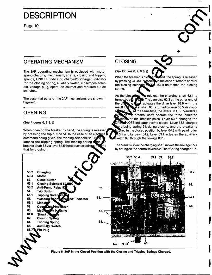
OPERATING MECHANISM
The 3AF operating mechanism is equipped with motor, spring-charging mechanism, shafts, closing and tripping springs, ON/OFF indicator, charged/discharged indicator for the closing spring, auxiliary switch, close/open solenoid, voltage plug, operation counter and required cut-off switches.
The essential parts of the 3AF mechanisms are shown in Figure 6.
OPENING
(See Figures 6, 7 & 8)
When opening the breaker by hand, the spring is released by pressing the trip button 54. In the case of an electrical command being given, the tripping solenoid 52T (54.1) un· latches the tripping spring. The tripping spring turns the breaker shaft 63 via lever 63.5 the sequence being similar to that for closing.
50.2 Charging 50.4 Motor 53. Close Button 53.1 Closing Solenoid 52 SRC 53.2 Anti-Pump Relay 52Y 62. 54. Trip Button 54.1 Tripping Solenoid, 52T 55. "Cl
o
sing Spring Charged" Indicator 55.1 55.1 Linkage 58. Open/Close Indicator 60. Mechanism Housing 55. 61.8 Shock Absorber 62. Closing Spring 64. Tripping Spring 58. 68. Auxiliary Switch 68.7 Pin Plug
.-
CLOSING
(See Figures 6, 7, 8 & 9)
When the breaker is closed by hand, the spring is released by pressing CLOSE button 53. In the case of remote control the closing solenoid 52SRC (53.1) unlatches the closing spring.
As the closing spring relaxes, the charging shaft 62.1 is turned by crank 62.2. The cam disc 62.3 at the other end of the charging shaft actuates the drive lever 62.6 with the result that breaker shaft 63. is turned by lever 63.5 via coupling rod 62.8. At the same time, the levers 63.1, 63.5 and 63.7 fixed on the breaker shaft operate the three insulated couplers for the breaker poles. Lever 63.7 changes the OPEN/CLOSE indicator over to closed. Lever 63.5 charges the tripping spring 64. during closing, and the breaker is latched in the closed position by lever 64.3 with pawl roller 64.3.1 and by pawl 64.2. Lever 63.1 actuates the auxiliary switch 68. through the linkage 68.1.
The crank 62.2 on the charging shaft moves the linkage 55.1 by acting on the control lever 55.2. The "Spring charged" in-
50.2 50.4 53.1 53. 68.7
53.2
68.
54.1
54.
Figure 6. 3AF in the Closed Position with the Closing and Tripping Springs Charged.
I ( I I I I I I I I I I I I ' ' I I www .
Elec
tricalP
artM
anua
ls . c
om

----------------�---------------1 DESCRIPTION
Page10
OPERATING MECHANISM
The 3AF operating mechanism is equipped with motor, spring-charging mechanism, shafts, closing and tripping springs, ON/OFF indicator, charged/discharged indicator for the closing spring, auxiliary switch, close/open solenoid, voltage plug, operation counter and required cut-off switches.
The essential parts of the 3AF mechanisms are shown in Figure 6.
OPENING
(See Figures 6, 7 & 8)
When opening the breaker by hand, the spring is released by pressing the trip button 54. In the case of an electrical command being given, the tripping solenoid 52T (54.1) unlatches the tripping spring. The tripping spring turns the breaker shaft 63 via lever 63.5 the sequence being similar to that for closing.
50.2 Charging 50.4 Motor 53. Close Button 53.1 Closing Solenoid 52 SRC 53.2 Anti-Pump Relay 52Y 62. 54. Trip Button 54.1 Tripping Solenoid, 52T 55. "Cl
o
sing Spring Charged" Indicator 55.1 55.1 Linkage 58. Open/Close Indicator 60. Mechanism Housing 55. 61.8 Shock Absorber 62. Closing Spring 64. Tripping Spring 58. 68. Auxiliary Switch 68.7 Pin Plug
CLOSING
(See Figures 6, 7, 8 & 9) When the breaker is closed by hand, the spring is released by pressing CLOSE button 53. In the case of remote control the closing solenoid 52SRC (53.1) unlatches the closing spring.
As the closing spring relaxes, the charging shaft 62.1 is turned by crank 62.2. The cam disc 62.3 at the other end of the charging shaft actuates the drive lever 62.6 with the result that breaker shaft 63. is turned by lever 63.5 via coupling rod 62.8. At the same time, the levers 63.1, 63.5 and 63.7 fixed on the breaker shaft operate the three insulated couplers for the breaker poles. Lever 63.7 changes the OPEN/CLOSE indicator over to closed. Lever 63.5 charges the tripping spring 64. during closing, and the breaker is latched in the closed position by lever 64.3 with pawl roller 64.3.1 and by pawl 64.2. Lever 63.1 actuates the auxiliary switch 68. through the linkage 68.1.
The crank 62.2 on the charging shaft moves the linkage 55.1 by acting on the control lever 55.2. The "Spring charged" in-
50.2 50.4 53.1 53. 68.7
53.2
68.
54.1
54.
Figure 6. 3AF in the Closed Position with the Closing and Tripping Springs Charged.
il I I I
ll
I I I I I I I ' I J www .
Elec
tricalP
artM
anua
ls . c
om

I
1
J) T
DESCRIPTION
dication is thus cancelled. The limit switches 5 0.4.1 switch in the control supply are actuated to the effect that the closing spring is recharged immediately.
53. Close Button 54. Trip Button 55. "Closing Spring
Charged" Indicator 58. Open/Close Indicator 62. Closing Spring 62. 62.5 Lever 62.5.1 Latch Roller 62.5.2 Latch 55. 63. Breaker Shaft 64. Tripping Spring 64.2 Latch 58. 64.3 Lever 64.3.1 Latch Roller
62.5 5.1 5.2
Figure 7. 3AF in Closed Position (Tripping Spring Charged and Latched)
48. Insulated Coupler 50.4.1 Limit Switch 54. Trip Button 50.4.1 63. Breaker Shaft 63.1 Lever 63.5 Lever 63.7 Lever 64.2 Latch 64.3 Lever 64.3.1 Latch Roller 68.1 Linkage
Figure 8. Breaker Shaft in the OPEN Position
Page 11
68.1
54. 64.2
64.3.1
www . El
ectric
alPar
tMan
uals
. com

OESCRI PTION
Page12
CHARGING
(See Figures 7, 8 & 9)
The charging shaft 62.1 is supported in the charging mechanism 50.2 but is not coupled mechanically with the charging mechanism. Fitted to it are the crank 62.2 at one end and the cam 62.3 together with lever 62.5 at the other.
When the charging mechanism is actuated by hand or by a
motor, the flange 50.3 turns until the drive 50.3.1 locates in the cutaway part of cam disc 62.3, thus causing the charging shaft to follow. The crank 62.2 charges the closing spring 62. When this has been fully tensioned, the crank actuates the linkage 55.1 for the "Closing spring charged" indicator 55. via control lever 55.2 and also the limit switches 50.4.1 for interrupting the motor supply. At the same time, the lever 62.5 at the other end of the charging shaft is securely locked by the latching device. When the closing spring is being charged, cam disc 62.3 follows idly, and it is brought into position for closing.
55.2 50.1 .2 .3 .3.1 62.3 .5 .5.1
62.1 .2
50.1 50.2 50.3 50.3.1 50.4 53. 55.1 55.2
ss.1 --so.4 62.6 62.8
Opening for Handcrank Charging Mechanism Charging Flange Driver Motor Close Button Linkage Control Lever
53.
62. 62.1 62.2 62.3 62.5 62.5.1 62.6 62.8
Closing Spring Charging Shaft Crank Cam Lever Latch Roller Drive Lever Coupling Rod
Figure 9. Closing Assembly with Slack Closing Spring
:.
l I I I I I I
' I J ' , ' ' ' ' I r
www . El
ectric
alPar
tMan
uals
. com

INSTALLATION
SHIPMENT AN D STORAGE
Shipping and storage considerations were described in the GENERAL section of this manual. They should be reviewed again at the time of installation. The breaker should be checked again to ensure that all parts are proper. Review lifting instructions (Figure 1).
LOCATION
The breaker should be located so that it is readily accessible for manual operation and inspection, and it has ample clearance to other apparatus or structures. It is advisable to provide a cement pad into which are imbedded suitable foundation bolts. The foundation should be reasonably level and it is recommended that .7 5 inch diameter anchor bolts be used.
Place the breaker on the foundation, and tighten the hold down bolts. The breaker must be level but no special leveling procedures are required. The breaker is adjustable in height for flexibility and to meet the various electrical codes. While the breaker is being lifted into position, adjust the leg extensions per the specific height requirement. After the breaker has been secured on the foundation, the electrical connections can be made to the de-energized lines.
A DANGER
i Hazardous voltage. Will cause personal injury or death.
The user must adjust the breaker height to insure compliance with safety codes for electrical c learance.
The breaker is shipped in the open position with all springs discharged. No blocking is used to prevent closing or tripping.
Page13
PRIMARY LEA D CONNECTIONS
The primary leads should be brought down from above the breaker if possible, with adequate clearance to other parts, and with the proper supports so that the breaker bushings are not subjected to excessive strains. They should be sized to have a capacity at least equal to the maximum operating current of the circuit and within the rating of the breaker. Connections are to be made to the bolted terminals of the bushings and must be securely tightened to a clean bright ·surface to assure good contact.
GROUN D CONNECTION
Diagonally opposite grounding pads are provided for connecting the mounting frame to ground using at least a 4/0 awg conductor. A good low resistance ground is essential for adequate protection.
SECON DARY AN D CONTROL
WIRING
A conduit panel opening is provided in the bottom of the relay and control power compartment for the connection of the control circuits. The control wires should be run separately from high voltage wiring to prevent inductive coupling between them and should be sized for full operating current to avoid a drop in voltage below that specified on the nameplate. All conduits should be sealed off at their entrance to the relay and control power compartment.
Terminal blocks are provided inside the relay and control power compartment for the connections necessary for the control wiring, bushing current transformers and relay panel when provided. Connection diagrams are supplied with each breaker to show the proper connections. These diagrams will be found in the pocket provided on the inside of the left hand door for this compartment.
FINAL INSTALLING INSPECTION
1 . Make sure that the breaker is properly set up and level on its foundation.
www . El
ectric
alPar
tMan
uals
. com

.INSTALLATION Page14
2. M ake a check for the t ightnass of all hardware on the cabinet, adjustable legs, bushings, bus bars and operating mechanism.
3. See that all bearing surfaces of the operating and breaker mechanism have been lubricated.
4. Inspect all insulated wiring to see that it has not been damaged, and test for possible grounds or short circuits.
5. See that all covers, doors and bolted connectors are securely fastened.
6. Retouch any paint that has been damaged during installation.
7. Check to see that all mechanisms are free of any packing and operate freely.
A CAUTION
Styrofoam bracing between phase barriers. Can dam age circuit breaker.
Rem ove bracing before energizin g breaker high voltage.
8. Ex am ine t h e v acu u m int err u p ter en velopes for damage, and wipe t hem and other insulatin g parts with a clean dry cloth .
9. Charge the closing spring manually an d push the manual close to close the breaker.
)0. Observe the open-close position indicator an d operat ion counter for operation with a manual open.
1 1 . Energize the control circuits. The motor-gear unit should run to charge the closing spring then tu rn-off.
12. Close the circuit breaker electrically and veri fy that the breaker is closed and remains cl osed by checking the mechanical position indicator. Note that the motorgear unit will immediately run to charge the closing spring.
1 3. Trip the breaker electrically .
1 4. Repeat the close and trip operations several times.
1 5. Check the t ripping and closing times from coil energization to contact break or m ake.
1 6. Check the integrity of the vacu um interrupter by performing a hi-pot on each interrupter while in the open position . The interrupter hi-pot is to verify that dam age has not occurred durin g shipment and is not intended as a verification of the breakers dielectric rating. The voltage shou l d be raised gradually, and the contact gap should sustain 27 kV. 60 Hz AC for 1 m inute or 38 kV DC for 1 minute. If it does not, the interrupter is faulty an d m ust be replaced.
A CAUTION
Hazardous radiati on.
�.� Can cause personal injury.
6 To elimin ate this hazard the low fre-q uency withstand test must be per-formed with all covers on an d doors closed.
Observe the foll owing items when hi-pott i n g t h e vacuum interrupters.
A) Test personnel should remain at least 6 feet ( 1 80 em) away from the interrupter bei ng tested.
8) Tests should be performed with normal m etallic panels installed, and test personnel shou l d position themselves to take advantage of the shieldin g provided by the metallic barriers.
C) The circuit breaker bu shings and m etallic m i dband on the interrupter may retain a stat1c charge after the h i-pot test, so discharge with a grounded probe before han dling.
A DA NGER
Hazardous voltage. Can caus e pers on al inju ry, death or
i damage circuit breaker.
Do not tou ch or service until you have de-energized the high voltage, groun ded the en tran ce bu shin gs an d tu rned off con trol voltage.
I I I I I I J I I I I ' f ' J ' ' ' www .
Elec
tricalP
artM
anua
ls . c
om
'f
I ' I
INSTALLATION
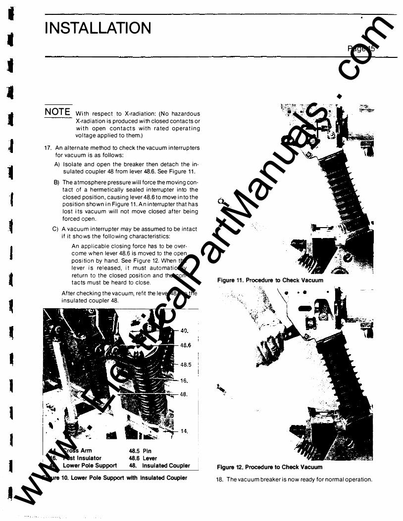
NOTE With respect to X-radiation: (No hazardous X-radiation is produced with closed contacts or wit h open conta ct s wit h rated operat ing voltage applied to them.)
17. An alternate method to check the vacuum interrupters for vacuum is as follows:
A) I solate and open the breaker then detach the in· sulated coupler 48 from lever 48.6. See Figure 11.
B) The atmosphere pressure will force the moving contact of a h ermetically sealed interrupter into the closed position, causing lever 48.6 to move into the position shown in Figure 11. An interrupter that has lost its vacuum will not move closed after being forced open.
C) A vacu u m interrupter may be assumed to be intact
' '
if it shows the following characteristics: An applicable closing force has to be overcome w hen lever 48.6 is moved to the open position by h and. See Figure 12. When the lever is released, it must automatically return to the closed position and the con· t acts m u st be heard to close.
After checking the vacuum, refit the lever 48.6 to the insulated coupler 48.
.. �·� ··�
1 4. Cross Ann 48.5 Pin 48.6 Lever 16. Post Insulator
40. Lower Pole Support 48. Insulated Coupler
Figure 10. Lower Pole Support with Insulated Coupler
Page15
Figure 11 . Procedure to Check Vacuum
Figure 12. Procedure to Check Vacuum
18. The vacuum breaker is now ready for normal operation.
www . El
ectric
alPar
tMan
uals
. com

E[.ECTRICAL CONTROL Page16
TYPICAL SCHEMATIC
The controls for the SDV-25 breaker are mounted in the 3AF mechanism housing. The controls consist of the motor cutoff switch 50.4 .1 (Figure 8), anti-pump relay directly
xo
41 21 22
52 y
21
LS22 14
XO 8 1 xo 82
xo C9 C10 C11 C12
5"52" 52 b 5� a 62 72 82 X 89 09 810 811 812
A2
LS3
below the pin plug 68.7 (Figure 6) auxiliary switch 68 (Figure 6), and the close lockout switch directly behind the manual trip button.
XOlC2
24 52
�� 52 T
34 A2 52
331 a
xo 02
C13 C14 C15 C16
Figure 13. Control Scheme for 3AF Operator
I I I I I I I I I I J ' J '
'
' www . El
ectric
alPar
tMan
uals
. com

I .I
ELECTRICAL CONTROL
SPRI NG CHARGI NG
The spring charging power is supplied through plug terminals A 1 and D16 (Figure 13). The LS21 and LS22 switches are shown with the closing springs discharged. When the control is energized, the motor 88 starts to charge the springs. The LS21 and LS22 switches are operated by control lever 55.2 (Figure 9) mounted on the charging mechanism 50.2 (Figure 9). The charging shaft revolves to the position of applying full tension, dead center, to t he springs. Beyond this position the LS21 and LS22 switches are actuated and the motor is cutoff.
CLOSI NG
When the close command is given, the circuit from plug terminal A2 through 52b, two sets of 52y contacts, LS8, LS9 to plug terminal 82 energizes the closing coil 52 SAC.
As soon as the closing springs are discharged the LS3 switch contact closes to energize the 52Y relay. I f the close control switch remains closed, the 52Y relay remains picked up through contact 52Y. The control switch has to be released to reset the close circuit for another closing operation. This forms the anti-pumping relay circuit which prevent s the circuit breaker from reclosing immediately after a trip-free operation. If control power is momentarily lost during closing, upon re-energizat ion, the 52Y relay picks up instantaneously through contact LS3 maintaining the anti-pumping relay circuit prior to complete spring charging.
Page17
TRIPPI NG
When the trip switch is closed the circuit from plug terminal C2 through 52a to plug t erminal D2 energizes the trip coii52T.
RECLOSI NG
The closing spring is recharged automatically as described above. Therefore, when the breaker i s closed both it s springs are charged (the closing spring charges the tripping spring during closing). As a result, the breaker is capable of an 0-t-CO operating cycle (dead time "t" i s 0.3 seconds).
www . El
ectric
alPar
tMan
uals
. com

ELECTRICAL CONTROL Page18
Control Voltage Applied
Motor88 M��----------------------------------------� Starts "'
LS21 and LS22 Cut Off
Motor 88
Closing Spring is
Charged
LS3 Interrupts the Circuit of 52Y The Breaker is
Ready for Operation
r-------------- ·-i-·-------------· - -------- ---l
52b(NC) Open Circuit of 52SRC
Blocked
52a (NO) Prepares
Closing Command When
Breaker Closed
Breaker Open
52SRC is Activated Via 52b(NC) and
the Two (NC) Contacts on 52Y
Closing Spring....._ ____ -r--1-- ----� Not Charged �
LS3 Closed, 52Y Picks Up Inter·
rupting the Circuit of 52SRC
r-----��----�
The Closing Spring is Unlatched
Shunt Release .,_ Auxiliary Switch Changes Over
The Circuit Breaker Closes 52T for Trip
The Tripping Spring is Charged
LS21 and LS22 Close and Start
Motor 88
. L--------·-·-· -·-·-·-·---·---------·-·-·-·-·-�
Figure 14. Complete Closing Sequence
t I I I I J I l '
www . El
ectric
alPar
tMan
uals
. com

'
• • •
ELECTRICAL CONTROL
( Trip Command
�,
52T Can Only Be Activated When
52a (NO) is Closed i.e. Breaker Must
Be Closed
� r
52T Unlatches the Tripping Spring
,,
Circuit Breaker Trips
Figure 15. Complete Tripping Sequence
Page19
( Continuous Closing Command
,, 52SRC Unlatches Closing Spring
and Breaker Closes
LS21, LS22 and LS3 Are Closed Because Closing Spring is Slack
Before Motor 88 Has Recharged the Closing Spring and Reopens LS3, 52Y Picks Up and Locks In
(Via the NO Contact)
52Y Interrupts the Circuit of 52SRC with 2 NC Contacts
52SRC Cannot be Reactivated Until the Continuous Closing
Command is Interrupted
Figure 16. Complete Anti·Pump Sequence
www . El
ectric
alPar
tMan
uals
. com

ADJUSTM ENTS Page20
G EN E RA L
Adjustable i tems are factory set and checked before and after numerous m echanical operat ion on every breaker to insu re correctn ess. No adjustmen t checking shou ld be n ecessary on new breakers. If a malfun ction occurs, check for h i dden sh ipping damage.
The followi ng will help you make the correct adjustments when replaci ng a broken or worn part.
CI RCU IT B R EAKER TI M I N G
A comparison of circu i t breaker t iming at any period of maintenan ce with t hat taken when the breaker was new wi ll i n di cate the operat ional condition of the breaker mechanism.
C los i ng Time Spr ing Charg i n g Time Opening T ime
83 m s * 1 5 s 32 ms*
* T h e val ue appl ies to t h e normal control voltage value. Closing Time = The t i me from instant of command in i t ia-
t ion unti l contacts are closed in all th ree poles.
Opening Time = The t i m e from instant of command in i t i at ion unt i l the contacts open in al l three poles.
Rotor Assembly
ROTOR ASSEMBLY
Barrier --...._ ;���· ----J:t11•• 1 --- 9
i ) :1- · � � / � ' I � ({((;> ,
Stationary ·, ·.. \ '..:./ �· '
Contact � , : __ .:;�:< � �: --- H _ _ @� ' �
AUXI LIARY SWITCH
The breaker i s equipped with a 22 stage auxiliary switch of which 1 1 stages are 52a contacts and 1 1 stag es are 52b contacts. However, only 10 stages of each are used. N i ne of the 52a stages are available for customer use and one is used within the operator for the t rip circu it. N i n e of the 52b stages are also available for customer use an d one is used within the operator for the close circu i t . The remain ing 52a and 52b stage is normally not used and reserved for oper· ator when a special control fun ct ion is required. The auxi liary switch also h as an impulse contact that closes duri ng an open or close operation for 10 ms. The impu lse con tact is normally not wi red.
The individual contacts of the swi tch can not be adjusted. The only adjustment is to change the length of the switch 's coup ling rod which will effect the ON and OFF posi t ion of all switch stages. The swi tch need only be adjusted such that the contacts are operated before the l im i t pos i t ions of the breaker. Th e coup l ing rod length is changed by the ad· justment s crew at the. lower end.
As a s pecial feature the breaker can be fi t ted with a type Q-10 auxiliary switch with (10) stag es. Each stage can be adj usted to be an 52a contact or 52b contact . Refer to figure 18 for feat ures of th is switch .
Figure 17. Type 0·10 Auxiliary Switch www . El
ectric
alPar
tMan
uals
. com

• • •
•
• tl
•
ADJUSTMENTS
TRI P LATCH A DJ USTM ENT
(See Figure 1 8)
Apply steady pressure to the armature of the opening
solenoid 54. 1 , (F igure 6) . The tr ip latch should release the open i n g spring before the l imit posit ion of the armature i s reached. T h e armature should have a free travel o f .39 t o . 6 i n c h ( 1 0 to 1 5mm) before picking up t h e load o f the trip latch. The armature stroke can be reduced by screwing out the adj ustment screw and increased by screwing in the same adj ustment screw. Secure the f inal adjustment by means of the lock nut. See Figure 18 for location of adjustment screw.
Adjustment Screw for Opening Solenoid and Trip Latch
0
0 c
0
Figure 18. Location of Trip Latch Adjustment Screw
C LOS E LATCH ADJ USTM E NT
(See F i gure 1 9)
Apply steady pressure to the armature of t he c losing solenoid 53. 1 , (F igure 7). The close latch should release the c los i n g spring before the l i m i t posit ion of the armature is reached. The armature should have a free travel of .39 to .6 in (1 0 to 1 5 m m) before picking up the load of the close latch. The close armature i s not adjusted, however, the travel of
Page 21
the closi n g cam support rol ler on the closi n g latch can be checked. The support roller on the clos i n g l atch should have an overlap of .31 in (8mm). See Figure 8, i tem 62.5. 1 and item 62.5.2.
Grease
Area Wiped Clean By Overlap of Latch Roller
Closing Latch
Figure 19. Closing Latch Measurement
Latch Roller
MOTO R C UT-OFF & ANTI PU M P
CONTROL SWITC H ES
The control lever that actuates the motor cut-off and antipump control switches is adj usted at the factory and shou ld not req u i re field adj ustment. T h i s same l ever operates the Spr ing Charged - S p r i n g D i s c h a rged i n d i cator. H owever, adj ustment of t h e actuation o f these devices can be made by bending the metal tab on the contro l lever 55.2. (Figure 9) up or down.
VACU U M INTERRUPTER STR O K E
ADJ UST M E N T
The f inal adjustment of the interrupter stroke m ust be made on ly after the i nterrupter has been operated a number of
t imes no-load to set the i nterrupter's contacts. The standard number of open-close operations for a new i n terrupter is 300.
Only after the mechanical operat ions should the interrupter stroke be set at .63 i n . :: .040 ( 1 6 m m :!" 1 m m ) .
New breakers w i l l b e shipped with a m i n i m u m of 300 mechanical operat ions logged on the operator and the stroke adjustment m ade. Replacement i nterrupters w i l l be suppl ied with 300 mechanical operat ions to set the contacts.
www . El
ectric
alPar
tMan
uals
. com

ADJUSTM ENTS Page22
Step #1 Set breaker in the open position with opening and c losing springs d i scharged. Remove al l electrical power from breaker controls.
Step #2 With the manual slow closing hand lever close
the breaker. When the interrupter is closed the contact e rosion mark must be fu l ly visible. See Fig u re 22.
Step #3 Measure and record the d imension · ·x, " as shown in Figure 20.
Step #4 With the hand lever. as in Step #2, hold down on the b reaker shaft with one hand and with the other hand release the tri p latch and allow the breaker to slow open.
Step #5 Measure and record d imension "�" as shown i n f igure 20. The d ifference between X, and X2 i s the i n terrupter stroke.
Step #6 Sho u l d the i nterrupter stroke not be with in l im its, .63 i n . :t .040, the eye bolt on the end of the
cou p l i n g rod can be screwed "in" to i ncrease or "out" to decrease the i nterrupter's stroke. Tighten t he locknut on the eye bolt after any adjustment.
Figure 20. Contact Measurements Travel
CONTACT P R ESSU RE SPR I NG STROKE T h e stroke o f t h e contact pressure spr ing i s the d i fference in the length of the spr ing when the breaker is closed and
o p e n ed . The p ress u re spr ing stroke should be . 1 7 to .44 i n ches.
Step #1 Set b reaker i n the open position and measure the length of the contact pressure spring for each i nterru pter. Record this d imension as "Y, ", see F igure 21 .
Step #2 Set b reaker in the closed position and measure the length of the spring. Record this d i mension as
Step #3 T h e stroke of the contact pressure spring is the d ifference between Y, and Y2 . The contact pressure spr ing stroke h as been preset at the factory and can not be changed.
Figure 21 . Contact Pressure Spring Measurement
www . El
ectric
alPar
tMan
uals
. com
•
A DJ USTM ENTS
Page 23
•
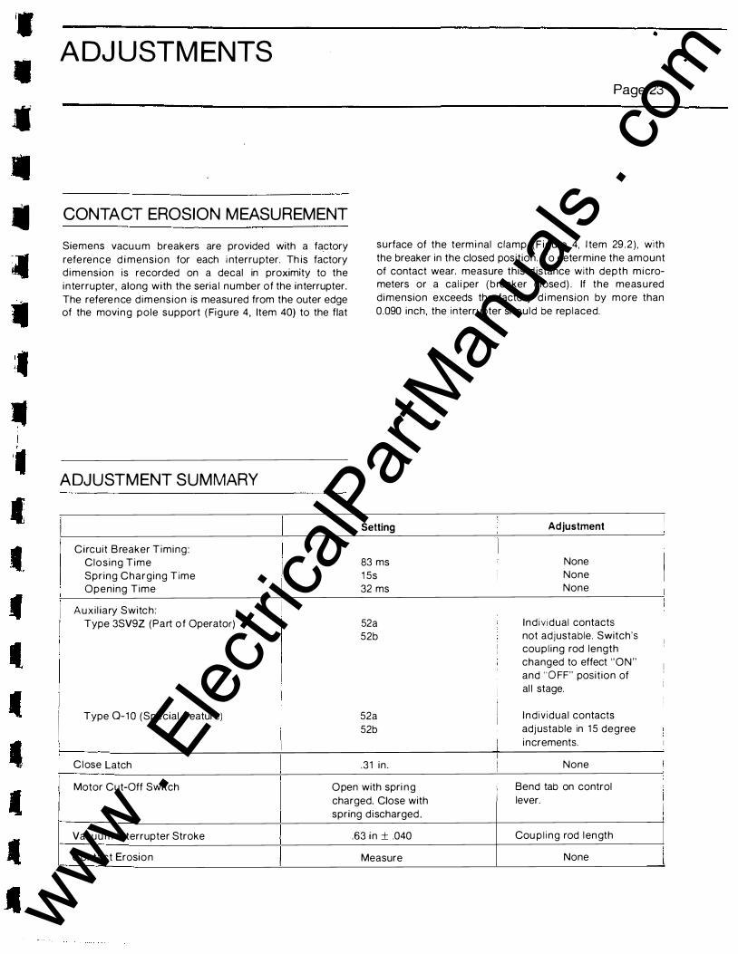
- CONTACT EROSION MEASUREMENT
Siemens vacu u m breakers are provided with a factory
refe rence d i mension for each i nterru pter. Th is factory d i mension is recorded on a decal in proximity to the
i n terrupter, along with the seria l number of the interrupter.
The refere n ce d i m ension is measu red from the outer edge of the movi n g pole support ( Figure 4, Item 40) to the flat
ADJUSTM ENT SUMMARY
Circuit B reaker Timing:
Clos ing Time
Spr ing Charging Time Opening Time
Auxi l iary Switch :
Type 3SV9Z (Part of Operator)
Type Q-1 0 (Special Feature)
C lose Latch
surface of the term i nal clamp (F igure 4, I tem 29 . 2 ) , with
the breaker in the closed position. To determine the amount
of contact wear. measure this d istance with depth m i crometers or a cal i per (breaker c losed) . If the meas u red
d i mension exceeds the factory d i mension by more than
0.090 inch, the interrupter shou ld be replaced.
Setting Adjustment
83 ms None
1 5s None
32 ms None
I
52 a Ind iv idual contacts
52b not adjustable. Switch's ! cou pl ing rod length
! changed to effect "ON" ! and ' ' O FF" posit ion of
al l stage.
52 a I n d i v idual contacts
52b adj ustable in 1 5 degree
l increments. I I
.31 in . I None I I
Motor Cut-Off Switch Open with spri n g i
Bend tab on control 't I charged. Close with lever. I
I spring d ischarged . I
Vacu u m I nterrupter Stroke .63 i n ± .040 Cou p l i n g rod l en gth
Contact Erosion Measure None J
www . El
ectric
alPar
tMan
uals
. com
' ' '
II
MAI NTENANCE
I N SPECTI O N SCH EDULE
A l ways i n s pect a b r e a k e r w h 1 c h has i n te rru p ted a h eavy
fa u l t c u rre n t . A l l c u rrent carry i n g J O i n ts s h o u l d be i ns pected to be s u re a l l contact su rfaces a re free of p rot r u s i o n s or l oose h a rd wa re .
One� a yea_r:, _a_g_t3_Q_����s_�,J_�I __ i r1spection mus_�_ b e carried -�U�i!d, if _��C�§�Ciry,__t_h_e -��!E!r i nsulat i ng -�Cid.!'l_'Adp�g down. Breaker Mechanism: The operating mechanis m must be oiled and lubricated every 10 years or after 10,000 openclose operat ions. Vacuum I nterrupters: The life expectancy (num ber of openclose operations) of the i nterrupters is a funct ion of the breaking current. They m u st be replaced after 30,000 mechanical operat ions or when the contacts have eroded by the max imum amount.
CONTACT EROSION
See i nstruct ions, page 23.
I NTER R U PTER VACUUM
A hi-pot test should b e applied t o the open interrupter contacts of each phase. An alternate method to check the vacuum wi thin the i nterrupters is to observe i f atmospheric pressure will force the moving contact shut.
A CAUT I O N
Hazardous radiation. Can cause personal inJ u ry .
To eli m i nate this hazard t he low freq u ency w i t hstand test m u st be performed wi th all covers on a n d d oo r s
closed.
Page25
HYDRA U LI C S HOC K ABSO R B E R
The 3AF mechanis m i s equ ipped with a hydraulic shock absorber and a stop bar that functions when the breaker opens. See i tem 61 .8 Figure 6. The shock absorber should requ ire no adj ustment. However, at maint enance checks . the shock absorber should b e examined for evidence of leaking. I f evi dence of flu i d leakage is found. the shock absorber must be replaced to prevent damage to the vacuum interrupter bellows.
I NTER R U PTER R E P LAC E M ENT
Replacement i nterrupters are furn1 shed as a complete assembly. They have been completely tested and d ie lectr ically and m echanically condi t ioned. The interrupters. when installed, do not requ i re that they be operated no-load a set num ber of t i mes or voltage tested to condit ion the contacts. Before starting any work the breaker shou ld be isolated. short-c i rcu i ted and g rounded. D isconnect the auxil i ary supply and open and close the breaker by hand unt i l both springs have been discharged. It IS recommended that one interrupter be removed and replaced completely rather than remov1ng two or more interrupters at a t ime. The following 1 S a step-by-step procedure for exchanging an interrupter
1 . 0 Remov i n g an I n terrupter (F ig ures 4 , Sa, S b & 10)
1 . 1 Loosen the bolt on terminal c lamp 29.2.
1 .2 Remove pin 48.S from i n s u lated c o u p l er 48 and l evers
48.6.
1 . 3 Remove the pin from adapter 36.3 . 1 .4 Remove t he bolts on struts 28 at the upper pole sup
port 20. 1 .S Remove the centenng ring 28. 1 . 1 .6 Remove the large bolt of pol e support 20 at insulator
16. 1 .
1 . 7 Li ft off t he complete pole support 20 together with the vacuum i nterrupter 30.
1 .8 Remove the nut on termi nal post 3 1 .2 and detach the vacuum i nterrupter 30 from the pole support 20.
I nstal l i ng an I n terrupter (Figures 2, 4, Sa, Sb & 1 0)
www . El
ectric
alPar
tMan
uals
. com
MAl NTENANCE Page 24
G EN E RAL
H1oroug�,, period ic inspection i s important to satisfactory operat ion. Inspection and maintenance f requency depends
on i nsta l l at ion, site, weather and atmospheric conditions, experience of operat i n g person nel and special operation requ i rements . Because of this, a wel l -plan ned and effective m a i ntenance prog ram depend largely on experience and practice.
A DAN G E R
H a za r d o u s v o l t a g e a n d m e c h a n 1 s m s .
S e v e r e perso n a l I n J u ry d u e to e l ectri cal
s h o c k . b u r n s and entan g l e m e n t 1n mov-
: n g p a rt s o r p ro perty d a m a g e W i l l res u l t
: i sa fety 1 n s t r u c t 1 o n s a re n o t f o l l owed .
Do n o t s e r·; 1 ce or t o u d l u n t 1 l -y o u h ave
d e-e n e r g 1 ze d h : g h v o l t a g e . g r o u n d ed a l i
t e r m 1 n a ! s a n d t u r n ec o f f co n t ro l voltage.
0 'l i y q u a l 1 f : e d o e rso n n e l s h o u l d work
ry, o r a r o u n d t h 1 s e q u 1 p m e n t a f t e r be
c o m i n g t h o rou g h l y f a m 1 l : a r w : t h al l warn
: n g s . safety n o t t c e s . : n s t ru ct , o ns a n d
m a : ntenance procec u res conta : ned h ere
I n T h e s u c c ess f u l a n d safe o perat :on
•J f t r, i s eq u i p m e n t : s d e p e n d e n t upon
p w p e r h a n d l i n g . msta l l at i o n . operat i o n
a n d m a m t e n a n c e .
;: :i , l u k t 'J p r •J o e r ! :; m a : nta : r: t h e eq u 1 pm e n t c a n resu l t 1 n se; ;ere perso n a l : n 1 u ry , product f a : l u re a n d p revent sucr;c;ssf u l f u r. c t 1 o n : n g o f c o n n e ct 8d c. p pa ratu s . The mstruct : o n s c o r: t a 1 n 8 d h e re 1 n sh o u l d be carefu l l y rev i ew e d , u n d e ro; t o o d ;md f o ' l o w e d . T h e f o l l o w 1 n g rn am t e n a n c e proced ur8s shou ld t)e pe rfor med reg u la r l y ·
S T E P 1 B r : s u re t h. a t t h e C i rC U i t breaker and its mechanism I S d : sr; r) n n e cted f m m al l e l e ct n c power. both h i g h volt a c; 8 a n rJ c o n t ro l voltage. befo re 1 t 1 S mspecfed or rep ,u rc:rJ
.S T E P 2 A t tr:r t r l •; r: 1 rC L I I t b reake r h a s bec;n d i scon n ected from pu·Nr: r I J rH;s a t t a c h t h e g r0 u n d 1 n g leRds p ro perly befor•: t o u d l l f1 'l iHI Y of t h e c 1 rc u 1 t brea ker p art s.
•
ST E P 3 I n s pect t h e operating m ec h a n i s m per i o d ical ly a n d keep t h e b e a r i n g s u rfaces of t h e togg le s . rods a n d l evers a d eq u ately l u b ricated w h ere req u i re d .
S T E P 4 Keep t h e m ec h a n i sm c lean.
S T E P 5 Be s u re t h e C i rc u i t breaker 1S wel l g ro u n de d .
S T E P 6 See t h at b o l t s . n uts. washers. cotte1· p i n s a n d a l l term i na l c o n nect 1 o ns are in p l ace and t 1 g h t .
S T E P 7' I n spect t h e b u s h m g ( i nsu lator) s u p po rts. as t h e v 1 b rat 1 o n d u e to t n e o perati o n of t h e c 1 rc u i t b re a k e r m a y cause t h e bu s h i n gs to m ove s l i g h t l y a n d res u l t m l oose h ardware.
STEP 8 C l ean t h e b u s h 1 n g s at reg u la r i n te rva l s w h e re a b n o rm a l c o n d 1 t 1 o n s s u c h as sa l t depos: ts . c e m e n t d ust o r a c 1 d f u m es. p reva i l to avo 1 d f lashovers resu l tmg from tne acc u m u l a t i O n of fore 1 g n s u bstances on b u s h 1 n g s u rfaces.
STEP 9 C l ean d n d . r f n ecessary. d ry t h e : n s u l at i n g materia ls across t h e 1 n terrupter a n d to g ro u n d o r parts of d i ffere n t p o te n t 1 a l .
STEP 1 0 At al l i ns pe c t 1 o n s operate t h e c i rc u 1 t b re a k e r by h an d to s e e t h at t h e mech a n 1 sm wo rks s m oo t h ly a n d correctly before o perat m g i t w1th power.
STEP 1 1 W h e n serv i C i n g , be certa i n to g r o u n d t h e o p posite e n d s of the I n t e r r u pter and t h e m 1 d b a n d r ings f o l l owIng t h e removal of the c i rc u i t b reaker f r o m serv1ce or fo l l o w i n g d i e l ectr ic tes t 1 n g before atte m pt i n g to hand le i nterru pters.
T h i s c h ec k l i st d o es n ot rep resent a n e x h a u st i v e su rvey of
m a i n t e n a n c e steps necessary to e n s u re safe o perat i o n of
the eq u i p m ent . Part i c u l a r a p p l i ca t i o n s may requ i re f u rt h e r
p ro ce d u re s . S h o u l d f u r t h e r i nf o r m a t i o n b e d e s i red o r
s h o u l d p art i c u l a r p r o b l e m s arise w h i ch are n o t covered
suff ic ient ly for t h e p u rchaser's p ur poses, the m atter s h o u l d
be refe rred to t h e l ocal S i e m e n s s a l e s off ic e .
T h e u s e of u na u t h o r ized parts i n t h e re p a i r o f t h e e q u i p m e n t . ta m p e n n g b y unqual i f i ed p e rs o n n e l , o r mcorrect adj ustments W i l l res u l t in d a n g e ro u s c o n d i t i o n s w h 1 c h can cause severe p e rso n a l i n J u ry or eq u 1 p m e n t d a m ag e . Follow a l l safety I nstruct ions contamed h er e m . www .
Elec
tricalP
artM
anua
ls . c
om
·------------------------------------------------------------------------------------
MAI NTENANCE Page26
N OTE T h e rep lacement interrupter w i l l b e equ i p ped
with adapter 36.3 that has been adj usted at the
factory. Do not alter the adapter sett ing.
2 . 1 A l l copper contact-making surfaces should be condit ioned before assembly. Th is is done by rubbing the surfaces vigorously with cri ss-crossing strokes unti l bright metal shows. Wipe off any metal dust with a c lean rag, apply a f i l m of acid-free vasel ine to t he surface and then bolt them together immediately. Make sure that the steel brush employed is used only for copper. The s i l verplated surfaces must be wi ped off with a c lean rag only and not wire brushed.
2.2 Posit ion the vacuum i nterrupter 30 in the pole support 20 with the evacuation nipple on the center section o f t h e interru pter faci n g the mechanism housing 60. Then screw the nut (complete with f lat washer and lock washer) on to terminal post 31 .2 f inger-t ight.
2.3 Insert vacu u m i n terrupter 30 together with the upper pole support 20 in the lower support 40. S l i p the term inal clamp 29.2 into posit ion and screw pole support 20 on the post insu lator 16. 1 . making a f i nger-t ight joint .
2.4 Refit the struts 28 to pole support 20 without t ig htening the screws.
2.5 Couple levers 48.6 and drive l i nks 48.9 to adapter 36.3 u s i ng the p i n suppl ied with the i nterrupter.
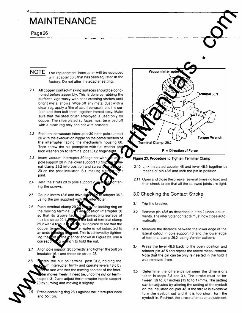
2.6 Push term ina l c lamp 29.2 against the lock ing ring on the movi ng terminal 36. 1 and position i nterrupter 30 so that i ts groove faces the connecting surface of f lexible strap 29. 1 . Tighten the bolt of term inal clamp 29.2 with a torque of 40 Nm, taking care to see that the copper term i n al of the interrupter is not subjected to an u ndo ben d i ng moment. This is achieved by t ightening the bolt in the manner shown in Figure 23. Use a correspond ing wrench to hold the nut.
2.7 Align pole sup port 20 correct ly and t ighten the bolt on insulator 16. 1 and those on struts 28.
2.8 Tighten the nut on termi nal post 31 .2, holding the vacu u m i nterrupter f irmly and operate levers 48.6 by
hand to see whether the moving contact of the i nterrupter moves freely. If need be, u ndo the nut on term inal post 31 .2 and adj ust the i nterrupter in pole support 20 by turn i n g and movin g it sl ight ly.
2.9 Press centeri n g ring 28.1 against the i nterrupter neck and bolt on.
Vacuum Interrupter 30.
Torque Wrench Terminal Clamp 29.2
P = Direction of Force
Figure 23. Procedure to Tighten Terminal Clamp
2. 1 0 Li nk insulated cou p ler 48 and lever 48.6 together by means of p in 48.5 and lock the p i n in posit ion.
2.1 1 Open and close the breaker several t i mes no-load and then check to see that al l the screwed joi nts are t ight .
3.0 Checking the Contact Stroke
3. 1 Trip t he breaker.
3.2 Remove pin 48.5 as described in step 2 under adjustments. The interrupter contacts must now close al.!tomatical ly.
3.3 Measure the distance between the lower edge of the lateral cutout in pole support 40, and the lower edge of term inal clamp 29.2, using Vern ier cal i pers.
3.4 Press the lever 48.6 back to the open position and rei nsert pin 48.5 and repeat the above measurement. Note t hat the pin can be only reinserted i n the hold it was removed from.
3.5 Determine the difference between the di mensions taken in steps 3.3 and 3.4. The stroke must be between .59 to .67 inches ( 1 5 to to 1 7mm). The sett ing can be adj usted by altering the sett ing of the eyebolt on the i nsu lated coupler 48. If the stroke is excessive
t u r n the eyebolt out and i f i t is too short, turn the eyebolt in. Recheck the stroke after each adjustment. www .
Elec
tricalP
artM
anua
ls . c
om
. I ' • '
I
• • '
IJ
I I .
•
MAI NTENANCE Page27
-� TYP 3 Pl aces
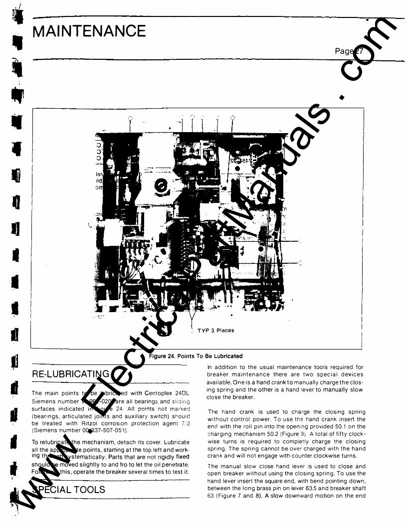
Figure 24. Points To Be Lubricated
R E-LUB RICATI N G
The main points to be l u bricated with Centoplex 24DL
S 1 e m e n s n u m ber W-962-020) are a l l bear ings and s l l cJ I It Q s u rfaces i n d i cated i n f i g u re 24. All poi nts n o t marked ( beari n g s , arti c u lated jo i nts and auxi l iary switch) shouid be treated with R itzol corrosion protection agent 7 ;2 (S iemens n u m be r 00-337-507-05 1 ) .
To rel u bricate the mechanism, detach its cover. Lubncat e
a l l the appropriate points, start ing at t he top left and working throu g h systematically. Parts that are not r igidly fixed should be moved s l i g htly to and fro to let the o i l p en etrate. Fol lowing this, operate the breaker several t imes to test it.
SPECIAL TOOLS
In addit ion to the usual maintenance too l s req u i red for breaker m a i n t e n a n c e there are two s p ec i a l d ev i c e s
ava i l able. O n e i s a hand crank t o manual ly charge t h e c los-
i n g spring and the other is a hand lever to manually slow
close the breaker.
The h a n d crank is used to charge the closing s p ri n g
w i t h o u t control power. T o u s e t h e hand c rank inse rt the end with the ro l l p i n i nto the ope n i n g provided 50. 1 o n the
charg 1 n g mec h a n i s m 50.2 ( F i g u re 9 ) A total of f ifty c l ock
wise turns is requi red to com pletly charge the c l os i n g s p r i n g . The s p ri n g cannot b e o v e r charged with t h e h a n d c ran k a n d w i l l n o t e n gage with counter clockwise turns.
The man ual s low c l ose hand lever is used to close and open b reaker w i t h o ut using the c losing spri n g . To use the
hand lever i nsert the square end, with bend pointing d ow n , between the l o n g brass p in on lever 63.5 a n d b reaker shaft
63 ( Fi g ure 7 and 8). A slow downward motion on the end www . El
ectric
alPar
tMan
uals
. com
M AINTENANCE
Page28
of the lever will rotate the breaker shaft thereby closing the breaker. A full rotation of the shaft is required for the trip latch 64.2 and latch roller to engage (Figure 8).
These devices are l isted and can be obtained from the factory.
Hand Crank Hand Lever
REPLACEMENT PA RTS
72-151-064-501 72-15Q-7 45-002
A list of replacement parts is sent with the breaker. A supply of these parts may be kept on hand so that the emergency repairs can be made without waiting for a shipment from the factory. Orders for replacement parts should be addressed to the nearest Siemens sales office and should include:
1 . Breaker Serial Number.
2. Type and rating of breaker from the nameplate.
3. Control voltage ( if applicable) from the nameplate.
4. Description of part.
5. Instruction book number, figure number and reference number. If none exists, a description or sketch should accompany the order.
6. Quantity required.
The breaker has a combination of inch and metric hardware. Al l the hardware used within the operator and interru pter m ounting is metric, while al l the remaining hardware used on the bushing and bus mounting and cabinet assembly, is inch. Avoid using the wrong tools when replacing any hardware.
B USH I NG
Bushings should be cleaned at regu lar intervals where abnormal conditions prevail. The bushing can be replaced by removing the bus to bushing stud hardware and clamping nuts on bushing mounting flange without affecting any other breaker part or adjustment. The breaker can be equ ipped with three bushing types. Refer to breaker approval drawing for bushing type provided and dimensions.
1 . Oil Fi l led Porcelain
This bushing is equipped with an upper porcelain housing, an oil sight gauge, a cast aluminum mounting flange and g round sleeve and cast epoxy lower
housing. The oil level in the transparent oil reservoir wil l vary with temperature as shown:
Oil Level Oil Temperature High 65 Degrees C (149 Degrees F) Normal 25 Degrees C ( 77 Degrees F) low -40 Degrees C ( -40 Degrees F)
Since the temperature-pressure relation for the 0il and the expansion space was establ ished at 25° C. the bushing fill plug shou ld be removed and oil added only at 20° C-25° C.
2. Dry Type Porcelain
This bushing is a one piece porcelain with a center through conductor. The mounting flange is part of the porcelai n structure and mounted with a two part clamping flange.
BUSH I N G C U R R ENT TRANSFORMER
The high voltage bush ings extend through bushing current transformers mounted in the cover of the high voltage c o m partment, Th ree transformers are sta ndard on each vacuum breaker, however, the BCT nameplate shou ld be checked for the exact number, location and rating. Space is available for 1 2 BCT's per breaker. The bushing current transformer connections are wired to separate terminal blocks located in the control and relay compartment.
A DA NGER
Hazardous voltage. Wi l l cause personal In JUry, death or damage circuit breaker.
Cu rrent transformers m ust not be operated with an open circuit and must be either connected to a burden or short circuited and grounded at the terminal blocks.
--- - - ----- w wwAwccc"·'.S""'"' -
www . El
ectric
alPar
tMan
uals
. com

-r
� '
� I
MAI NTENANCE
RELAY PANEL
The breaker can be equipped with a relay panel when required. A relay package can be supplied on a hinged panel mounted in the front of the control compartment. The following items can be accommodated on the swing out panel:
� · '·o'· ·"'""---
Page 2 9
1 . Breaker control switch with red and green indicating lights
2. Three overcurrent phase relays 3. One overcurrent ground relay 4. Three ammeters 5. One automatic reclosing relay
Refer to the wiring and schematic diagrams, and other instruction literature shipped with the breaker for additional specific relay requirements.
• www .
Elec
tricalP
artM
anua
ls . c
om

• www .
Elec
tricalP
artM
anua
ls . c
om

S I E M E NS
10/88
Siemens Energy & Automation, I nc.
•
Power C o m po nents Division
J ackson, M S 39208
(601 ) 939-0550
P R INTED I N U.S. A. www . El
ectric
alPar
tMan
uals
. com