i n st r uc t io n man ua l
TRANSCRIPT

-1-
TDK-Lambda HWS1000/ME Series INSTRUCTION MANUAL
HWS 1000/ME Series Instruction Manual
BEFORE USING THE POWER SUPPLY UNIT Be sure to read this instruction manual thoroughly before using this product. Pay attention to all cautions and warnings before using this product. Incorrect usage could lead to an electrical shock, damage to the unit or a fire hazard.
DANGER · Never use this product in locations where flammable gas or ignitable substances are present.
INSTALLATION WARNING
· When installing, ensure that work is done in accordance with the instruction manual. When installation is improper, there is risk of electric shock and fire.
· Installation shall be done by Service personnel with necessary and appropriate technical training and experience. There is a risk of electric shock and fire.
· Do not cover the product with cloth or paper etc. Do not place anything flammable around. This might cause damage, electric shock or fire.
WARNING on USE
· Do not touch this product or its internal components while circuit in operation, or shortly after shutdown. You may receive a burn. · While this product is operating, keep your hands and face away from it as you may be injured by an unexpected situation. · For products with no cover, do not touch them as there are high-voltage and high temperature parts inside.
Touching them might cause injury such as electric shock or burn. · There are cases where high voltage charge remains inside the product immediately after the input is cut off.
Therefore, do not touch even if they are not in operation as you might get injured due to high voltage and high temperature. You might also get electric shock or burn.
· Do not make unauthorized changes to this product nor remove the cover as you might get an electric shock or might damage the product. We will not be held responsible after the product has been modified, changed or dis-assembled.
· Do not use this product under unusual condition such as emission of smoke or abnormal smell and sound etc. Please stop using it immediately and shut off the product. It might lead to fire and electric shock. In such cases, please contact us. Do not attempt repair by yourself, as it is dangerous for the user.
· Do not operate and store these products in environments where condensation occurs due to moisture and humidity. It might lead fire and electric shock.
· Do not drop or apply shock to this product. It might cause failure. Do not operate these products mechanical stress is applied. · When necessary, this products is to be repaired only by us or our authorized agents. It is important that this product cannot be used
in hazardous environments (facilities such as nuclear power control system or life support equipment) without our written consent. · Do not drop or insert anything into unit. It might cause failure and fire, when using the unit under such condition. · The outputs of these products must be earthed in the end use equipment to maintain SELV.
If the outputs are not earthed, they must be considered hazardous and must not be made user accessible.
CAUTION on MOUNTING · Confirm connections to input/output terminals are correct as indicated in the instruction manual before switching on. · Input voltage, Output current, Output power, ambient temperature and ambient humidity should be kept within specifications,
otherwise the product will be damaged. · Input line, please use the wires as short and thick as possible. · Do not use this product in special environment with strong electromagnetic field, corrosive gas or conductive substances and
direct sunlight, or places where product is exposed to water or rain. · Mount this product properly in accordance with the instruction manual, mounting direction and shall be properly ventilated. · Please shut down the input when connecting input and output of the product. · When installing in environment where conductive foreign, dust and liquid may be present, please consider penetration of above
foreign material in the power supply by installing filter, to prevent trouble or malfunction. · This power supply is primarily designed and manufactured to use and enclose in other equipment. · This power supply unit has a built-in fan for air-cooling. Do not block air intake and exhaust. It might cause fire. · Do not operate and store this unit at the condition of condensation. In such case, waterproof treatment is necessary.
DA032-04-80/ME-E

-2-
TDK-Lambda HWS1000/ME Series INSTRUCTION MANUAL
· Do not operate this unit after it falls down. · The output voltage of this power supply unit is considered to be a hazardous energy level (The voltage is 2V or more and the
electric power is 240VA or more), prevention from direct contact with voltage output is highly necessary. While installing or servicing this power supply unit, avoid dropping tools by mistake or direct contact with voltage output. This might cause an electrical shock. While repairing this power supply unit, the AC input power must be switch off and the I/O terminal voltage should be less than the safety level.
CAUTION on USE · Product individual notes are shown in the instruction manual.
If there is any difference with common notes individual notes shall have priority. · Before using this product, be sure to read the catalog and instruction manual.
There is risk of electric shock or damage to the product or fire due to improper use. · Input voltage, Output current, Output power, ambient temperature and ambient humidity should be kept within specifications,
otherwise the product will be damaged, or cause electric shock or fire. · If the built-in fuse is blown, do not use the product even after replacing the fuse, as there is risk of abnormality inside.
Be sure to request repair to our company. · For products without built-in protection circuit (element, fuse, etc.), insert fuse at the input to prevent smoke, fire during abnormal
operation. As for products with built-in protection circuit, depending on usage conditions, built-in protection circuit might not work. It is recommended to provide separate proper protection circuit.
· For externally mounted fuse do not use other fuses aside from our specified and recommended fuse. · This product was made for general purpose electronic equipment use and is not designed for applications requiring high safety
(such as extremely high reliability and safety requirements. Even though high reliability and safety are not required, this product should not be used directly for applications that have serious risk for life and physical safety. Take sufficient consideration in fail-safe design (such as providing protective circuit or protective device inside the system, providing redundant circuit to ensure no instability when single device failure occurs).
· When used in environments with strong electromagnetic field, there is possibility of product damage due to malfunction. · When used in environment with corrosive gas (hydrogen sulfide, sulfur dioxide, etc.), there is possibility that they might penetrate
the product and lead to failure. · When used in environments where there is conductive foreign matter or dust, there is possibility of product failure or malfunction. · Provide countermeasure for prevention of lightning surge voltage as there is risk of damage due to abnormal voltage. · Connect together the frame ground terminal of the product and the ground terminal of the equipment for safety and noise reduction.
If these ground is not connected together, there is risk of electric shock. · Parts with lifetime specifications (built-in electrolytic capacitor) are required to be replaced periodically.
Set the overhaul period depending on the environment of usage and perform maintenance. Also, note that there are cases when EOL products cannot be overhauled.
· Take care not to apply external abnormal voltage to the output. Especially, applying reverse voltage or overvoltage more than the rated voltage to the output might cause failure, electric shock or fire.
· This product is designed under condition Material group Ⅲb, Pollution Degree (PD): PD2, Over Voltage category (OVC): OVC Ⅱ and Class of equipment: Class Ⅰ. This product is designed to be accessible only to service technicians as part of indoor use device.
· These products are not authorized for use as critical components in nuclear control systems, life support systems, vehicle, ship, aerospace or equipment for use in hazardous environments without the express written approval of the Managing Director of TDK-Lambda Corp..
GENERAL INSTALLATION INSTRUCTIONS
· These products are Class 1 and must therefore be reliably earthed and professionally installed in accordance with the prevailing electrical wiring regulations and the safety standards covered herein.
· These products are IPX0, and therefore chemicals/solvents, cleaning agents and other liquids must not be used. · The first protective earth connection in the final installation must be marked with the protective earth symbol.

-3-
TDK-Lambda HWS1000/ME Series INSTRUCTION MANUAL
Special Instructions for IEC/EN/UL/CSA 60601-1 · These products are designed for continuous operation within an overall enclosure, and must be mounted such that access to the
mains terminals is restricted. See Clause 16, IEC/EN/UL60601-1. · These products are NOT suitable for use in the presence of flammable anaesthetic mixtures with air or with oxygen or with nitrous
oxide. · These products are classed as ordinary equipment according to IEC/EN/UL60601-1 and are NOT protected against the ingress of
water. · Connect only apparatus complying with IEC/EN/UL60601-1 to the signal ports. · Except for permanently installed equipment as defined in Clause 57.6 of IEC/EN/UL60601-1 the overall equipment in which these
products are installed must have double pole fusing on the input mains supply. The products themselves have single pole fusing in the live line.
· These products provide the following insulation between mains and output. (a) As for UL60601-1 : 2006 (1st Ed.), EN60601-1 : 1990+A1+A2+A13 and CSA C22.2 No.601-1:M90, 2005,
basic insulation provided. Sure to add supplemental insulation to input or output in the equipment. (b) As for ANSI AAMI/ES60601-1 : 2005, EN60601-1 : 2006 and CSA C22.2 No.60601-1 : 08, reinforced
insulation (2MOOP) provided. · When the PSU is installed within medical equipment an all pole mains input disconnect device must be fitted. · Reference should be made to local regulations concerning the disposal of these products at the end of their useful life. · The maximum normal leakage current of this product is 500 microamperes for IEC/EN/UL60601-1.
When using it as a patient care equipment, all outer surfaces of the equipment shall be constructed of nonconductive material. See Clause 19.5DV.2 of UL60601-1.
· These products have not been assessed to IEC/EN60601-1-2 (EMC) but EMC test data is available from TDK-Lambda Corp..
Note · Take note that traces of sheet metal processing be left in our power supplies. · When disposing product, follow disposal laws of each municipality. · Published EMI (CE, RE) or immunity is the result when measured in our standard measurement conditions and might not satisfy
specification when mounted and wired inside end-user equipment. Use the product after sufficiently evaluating at actual end-user equipment.
· When exporting our products, apply for necessary permissions as required by rules and regulations of Foreign Exchange and Foreign Trade Control Act.
· Catalogue, contents of the instruction manual may be changed without a prior notice. Refer to latest catalogue or instruction manual · Reproduction or reprinting the instruction manual or its portion is forbidden without our permission.
LONG-TERM STORAGE METHOD AND LONG-TERM STORAGE PERIOD · Please keep the product in carton box. · Please do not apply excessive vibration, shock or mechanical stress applied directly to the product. · Please keep away from direct sunlight. · For long-term storage temperature and humidity, the following conditions shall be used as a guideline :
Temperature range : 5℃~30℃ Humidity range : 40%~60%RH Please keep away from the places where temperature and humidity can change drastically. It can cause condensation on the product or deterioration.
· For long-term storage period, we recommend to use within 2 years after receiving the product. There is tendency that the leakage current of an aluminum electrolytic capacitor may increase when stored without using for a long time. This phenomenon can be improved by applying voltage to the aluminum electrolytic capacitor to reduce the increased leakage current through the self-recovery effect of the electrolyte. For reference, before using products that have been stored for a very long time, please warm-up first for 30 minutes or more without taking load.
< Criterion of warm up voltage condition > (1)Implementation period : 1 year or above after the delivery (2)Electrical continuity condition
Input voltage : Rating Load : 0A Ambient temperature : Normal temperature Time : 30 minutes or more

-4-
TDK-Lambda HWS1000/ME Series INSTRUCTION MANUAL
1. Model name identification method
HWS1000-24 /ME
Option Rated Output Voltage Output Power type Series name 2. Terminal Explanation Please pay extra attention to the wiring. Incorrect connection will damage the power supply. · When connecting input and output wiring, input AC-Line should be off. · Input wiring and output wiring shall be separated, otherwise noise susceptibility of power supply unit will be
weak. · Ground terminal (E) must be connected to the instrument chassis and the chassis of this power supply unit . · Remote sensing lines shall be twisted or use the shielded wire. · Remote ON/OFF control lines shall be twisted or use the shielded wire. 2-1. Front Panel Explanation
HWS1000 Front Panel ① + : + Output terminal ② - : - Output terminal ③ ON : Output (Power On) indication green LED
(The indicator turns on when the power supply output is in normal operating condition.) ④ V.ADJ :Output voltage adjust trimmer (The output voltage rises when trimmer is turned clockwise.) ⑤ CN01: Remote sensing, ON/OFF control signal, Current balance signal, ⑥ CN02: Output voltage external control signal and Power fail signal output connector. ⑦ N : AC input terminal N : Neutral line ⑧ L : AC input terminal L : Live Line (Fuse in line) ⑨ E : Ground terminal
1
8
2
5
6
3
4
7
9
NAME PLATE
E

-5-
TDK-Lambda HWS1000/ME Series INSTRUCTION MANUAL
2-2. CN01, CN02 Connector pin configuration and Function CN01, CN02 pin configuration and function are the same. They are connected to each other in this power supply unit. When the pin of CN01 side is shorted the same function pins of CN02 side are shorted. Please note that the function cannot be separately set with CN01 and CN02.
Pin No. Configuration Function
1 +V Connected to +Output terminal in this Power supply unit. (+V terminal can not supply load current.)
2 +S Remote sensing terminal for + output (For remote sensing function, which compensates for line drop between power supply terminals and load terminals. Connect to +V terminal when remote sensing function is unnecessary)
3 -V Connected to -Output terminal in this Power supply unit. (-V terminal can not supply load current)
4 -S
Remote sensing terminal for - output (For remote sensing function, which compensates for line drop between power supply terminals and load terminals. Connect to -V terminal when remote sensing function is unnecessary)
5 PC Current balance terminal (For output current balancing in parallel operation.)
6 COM Ground for PC and PV signal.
7 PV Output voltage external control terminal (For power supply output voltage control with an external voltage. Connect it with the terminal REF when PV function is unnecessary. )
8 REF Reference Voltage terminal for Output voltage control (REF and PV are connected when shipping.)
9 CNT Remote ON/OFF control terminal (When the CNT is pulled to TTL low, the power supply turns on.)
10 TOG Ground for CNT and PF signal.
11 PF Power fail signal output terminal. (As the output voltage drops, FAN stops and AC input voltage down, open collector output, “Power Fail” signal will output “High”.)
12 TOG Ground for CNT and PF signal. CN01、CN02 are connected in this power supply unit as follows. CN01
1 3 5 7 9 11 2 4 6 8 10 12
CN02
1 3 5 7 9 11 2 4 6 8 10 12
Output ON/OFF Control circuit
Power fail signal generation circuit
Reference voltage generation circuit
※Output ON/OFF control circuit and the Power fail signal circuit are insulated with other circuits in the power supply. (Insulating voltage AC100V)
Output current signal circuit
Output voltage detection circuit
CN01
1 3 5 7 9 11
4
2
6 8 10 12
CN02
1 3 5 7 9 11
4
2
6 8 10 12

-6-
TDK-Lambda HWS1000/ME Series INSTRUCTION MANUAL
Twist wire
2-3. Basic Connection (Local sensing) 2-4. Remote sensing required ①Connect “+S” terminal to “+V” terminal and
“-S” terminal to “-V” terminal with sensing wires.
②Connect “CNT” terminal to “TOG” terminal with wire.
③Connect “PV” terminal to “REF” terminal with wire.
※ Please use attachment connector for each connection.
※ In the following cases, the output is shut down. When CNT and TOG is opened. When PV and REF is opened.
①Connect “+S” terminal to “+” terminal of load with sensing wire
②Connect “-S” terminal to “-” terminal of load with sensing wires.
③Connect “CNT” terminal to “TOG” terminal with wire. ④Connect “PV” terminal to “REF” terminal with wire. ※ The accuracy of the output voltage will deteriorate
when the sensing terminals are opened. ※ In the following cases, the output is shut down.
When CNT and TOG is opened. When PV and REF is opened.
Attached connector when shipping Connecting circuit with CN01 or CN02 connector
1 3 5 7 9 11
2 4 6 8 10 12
1 3 5 7 9 11
2 4 6 8 10 12
M8 Bolts and nuts for connecting to the load line. (These are not attached to the product.)
Connector : (JST) S12B-PHDSS Attached connector when shipping ・Housing : (JST) PHDR-12VS ・Contact : (JST) SPHD-001T-P0.5 1-2, 3-4, 7-8, 9-10 are shorted.
M8 Bolts and nuts for connecting to the load line. (These are not attached to the product.)
Connector : (JST) S12B-PHDSS Remove standard attached connector, and use the harness made by the customer. ・Housing : (JST) PHDR-12VS ・Contact : (JST) SPHD-001T-P0.5 2-”+” of load, 4-”-” of load should be connected. 7-8, 9-10:should be shorted * Please use wire for contact and crimping tool specified by maker.
+
Red Black Brown Yellow
“-” of load
“+” of load
+ - - Load Load
NAME PLATE
E
NAME PLATE
E

-7-
TDK-Lambda HWS1000/ME Series INSTRUCTION MANUAL
2-5. Remote ON/OFF control required 2-6. PF signal output required ①Remove standard attached connector, and use the harness
made by the customer and connect external signal to between CNT and TOG terminal.
②“TOG” terminal is ground for “CNT” terminal. In case this function is not used, please short between CNT and TOG terminal.
①PF signal is an open collector output, therefore PF signal outputs is shown in circuit below.
②“TOG” terminal is ground for “PF” terminal.
Connecting circuit with CN01 or CN02 connector Connecting circuit with CN01 or CN02 connector
1 3 5 7 9 11
2 4 6 8 10 12
1 3 5 7 9 11
2 4 6 8 10 12
M8 Bolts and nuts for connecting to the load line (These are not attached to the product.)
Connector : (JST) S12B-PHDSS Remove standard attached connector, and use the harness made by the customer. ・Housing : (JST) PHDR-12VS ・Contact : (JST) SPHD-001T-P0.5 1-2, 3-4, 7-8:should be shorted 9:CNT
Should be connected to ON/OFF control signal. 10:TOG
Should be connected to Signal Ground. * Please use wire for contact and crimping tool specified by maker.
M8 Bolts and nuts for connecting to the load line (These are not attached to the product.)
Connector : (JST) S12B-PHDSS Remove standard attached connector, and use the harness made by the customer. ・Housing : (JST) PHDR-12VS ・Contact : (JST) SPHD-001T-P0.5 1-2, 3-4, 7-8, 9-10:should be shorted. 11:PF
Should be connected to PF signal output 12:TOG Should be connected to Signal Ground. * Please use wire for contact and crimping tool specified by maker.
- + - + Load Load
NAME PLATE
ON
PF signal output
To signal ground
NAME PLATE
E E

-8-
TDK-Lambda HWS1000/ME Series INSTRUCTION MANUAL
3. Block Diagram
Line
Filt
er
Rect
ifier
PFH
C Ci
rcui
t
Inru
sh C
urre
nt L
imit
Circ
uit
Filte
r
Switc
hing
Circ
uit
Cont
rol C
ircui
t
L
N
Cont
rol C
ircui
t
OCPCircuit
OTPCircuit
OVP Sensing
Photo-coupler
Rect
ifier
& F
ilter
Input85~265VAC
E
-
Output
CNTTOGRemote
ON/OFF Control
+S
-S
+
COM
PV
Output Current Balance
PC
PF
Standby supply
Latch
Circ
uit
OVPCircuit
UVPCircuit
Low output
Voltage Detection
Photo-coupler
DelayCircuit
Output SensingPhoto-
coupler
Reference Voltage
Photo-coupler
FAN
Photo-coupler
REF
· Circuit topology, Switching frequency
Half Bridge converter 46kHz PFHC Circuit : Active filter 63kHz · Fuse rating : 20A · E : Ground terminal

-9-
TDK-Lambda HWS1000/ME Series INSTRUCTION MANUAL
4. Sequence time chart
PF signal(Open collector)
INPU
T O
N
INPU
T O
FFIN
PUT
ON
INPU
T O
FF
Input Voltage
Output Voltage
Remote ON/OFF Control (※1)
REM
OTE
OFF
REM
OTE
ON
OVP
ACT
ION
OCP
REL
EASE
DO
CP A
CTIO
N
FAN
STO
P
OTP
ACT
ION
INPU
T O
N
OVP
ACT
ION
INPU
T O
FFIN
PUT
ON
OCP
ACT
ION
SHU
T D
OW
NIN
PUT
OFF
INPU
T O
N
FAN
ALM
ACT
ION
INPU
T O
FFIN
PUT
ON
0V
Vout
0V
PF Signal Point(80% or less)
H
L
H
L
OVP Point(※2)
5sec.(TYP)
5sec.(TYP)
OCP Point(105% or more)
(※3)
OCP(Shut down)
OVP Point(※2)
OCP
ACT
ION
OTP
ACT
ION
REM
OTE
OFF
REM
OTE
OFF
REM
OTE
OFF
REM
OTE
OFF
REM
OTE
ON
REM
OTE
ON
REM
OTE
ON
REM
OTE
ON
FAN
STO
PFA
N A
LM A
CTIO
N
SHU
T D
OW
N
5sec.(TYP)
5sec.(TYP)
OCP Point(105% or more)(※3)
OCP(Shut down)
(※1) Level
2.4V≦H≦12V or Open 0V≦L≦0.8V or Short
(※2) OVP Point 24V : 125%~145% 36V : 125%~138% 48V : 115%~125%
(※3) OCP Point (24V - 48V Model, Input voltage AC180 - 265V) ・Peak current : 127%(24V - 48V)
Peak current is less than 10 seconds, and duty 35% max. ・Overload exceeding 105%(without output dropping situation) continuously for
more than 10 seconds will result to output shutdown. Meanwhile, overload exceeding 105%(with output dropping) continuously for more than 5 seconds will result to output shutdown.
・OCP Point : More than 127%(24V - 48V)

-10-
TDK-Lambda HWS1000/ME Series INSTRUCTION MANUAL
5. Functions and Precautions 5-1. Input Voltage Range
Input voltage range is single phase 85 - 265VAC (47 - 63Hz). Input voltage, which is out of specification, may cause unit damage. Rated input voltage range fix during safety standard application is from100V to 240VAC (50/60Hz).
While applying input voltage from 85Vac to 90Vac, output load current derating is required. 5-2. Output Voltage Range
Output voltage is set to the rated value at shipping. V.ADJ trimmer on the front panel side is use to adjust the output voltage within the range specified. Output voltage trimming range is within -20% - +20% of the rated output voltage (48V model: -20% - +10%). Turn the trimmer clockwise to increase output voltage. Take note when the output voltage is increased excessively over voltage protection (OVP) function may trigger and output voltage will shut down.
Use the output power of the power supply below the rated output power value when you raise the output voltage. 5-3. Over Voltage Protection (OVP)
The OVP function (Inverter shut down method, manual reset type) is provided. OVP function operates within 125-145% of the rated DC output voltage value (36V model: 125-138%, 48V model: 115-125%), and the output will be shut down when OVP function triggers. When OVP function operates, the input power is cut off for a few minutes, and then power is re-input or remote ON/OFF control signal shall be input for recovery of the output. OVP value is fixed and can not be adjusted. 5-4. Over Current Protection (OCP)
The OCP function (Constant current limiting, Time delay shutdown type) is provided. OCP function operates when the output current exceeds 105% of maximum DC output current specification and the over current or short circuit condition continues 5-second or more, the output will be shut down. When the OCP is triggered, the input power is cut off for a few minutes, and then power is re-input or remote ON/OFF control signal should be input for recovery of the output. The OCP setting is fixed and not to be adjusted externally. 5-5. Over Temperature Protection (OTP)
Over temperature protection function (manual reset type) is provided. When ambient or internal temperature rises abnormally, OTP will shut down the output. When OTP is triggered, input power is cut off and allow sufficient cooling to reset the OTP function. Then power is re-input or remote ON/OFF control signal should be input for recovery of the output. 5-6. Low Output Detection Circuit (PF)
Low output voltage detection circuit is provided. Power Fail signal (PF signal) will output when output voltage decrease by either the drop or brown out of the input voltage or OCP, OVP and OTP function operation. PF signal will turn “High” level to indicate the abnormal status of the power supply when the output voltage decrease to 80% of the output voltage setting value. However, there is a possibility that PF signal may not output during parallel operation. The PF signal circuit is insulated from the power supply input and output circuit and it is an open collector. TOG terminal is ground for PF terminal.
When the Built-in Fan Motor of this power supply unit stops, PF signal will turn to “H” and the output power will shut down. The Built-in Fan Motor is a component with lifetime. We recommend a periodic replacement. Please contact our sales office. Replacement is at customer’s expenses.
PF
TOG
Vce max:30V Ic max:20mA
-11-
TDK-Lambda HWS1000/ME Series INSTRUCTION MANUAL
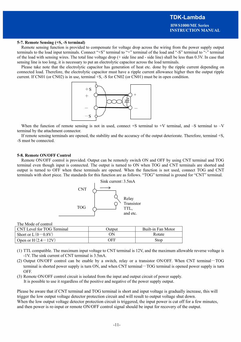
5-7. Remote Sensing (+S, -S terminal) Remote sensing function is provided to compensate for voltage drop across the wiring from the power supply output
terminals to the load input terminals. Connect “+S” terminal to “+” terminal of the load and “-S” terminal to “-” terminal of the load with sensing wires. The total line voltage drop (+ side line and - side line) shall be less than 0.3V. In case that sensing line is too long, it is necessary to put an electrolytic capacitor across the load terminals.
Please take note that the electrolytic capacitor has generation of heat etc. done by the ripple current depending on connected load. Therefore, the electrolytic capacitor must have a ripple current allowance higher then the output ripple current. If CN01 (or CN02) is in use, terminal +S, -S for CN02 (or CN01) must be in open condition.
When the function of remote sensing is not in used, connect +S terminal to +V terminal, and –S terminal to –V terminal by the attachment connector.
If remote sensing terminals are opened, the stability and the accuracy of the output deteriorate. Therefore, terminal +S, -S must be connected. 5-8. Remote ON/OFF Control
Remote ON/OFF control is provided. Output can be remotely switch ON and OFF by using CNT terminal and TOG terminal even though input is connected. The output is turned to ON when TOG and CNT terminals are shorted and output is turned to OFF when these terminals are opened. When the function is not used, connect TOG and CNT terminals with short piece. The standards for this function are as follows. “TOG” terminal is ground for “CNT” terminal. The Mode of control CNT Level for TOG Terminal Output Built-in Fan Motor Short or L(0-0.8V) ON Rotate Open or H(2.4-12V) OFF Stop (1) TTL compatible. The maximum input voltage to CNT terminal is 12V, and the maximum allowable reverse voltage is
-1V. The sink current of CNT terminal is 3.5mA. (2) Output ON/OFF control can be enable by a switch, relay or a transistor ON/OFF. When CNT terminal-TOG
terminal is shorted power supply is turn ON, and when CNT terminal-TOG terminal is opened power supply is turn OFF.
(3) Remote ON/OFF control circuit is isolated from the input and output circuit of power supply. It is possible to use it regardless of the positive and negative of the power supply output.
Please be aware that if CNT terminal and TOG terminal is short and input voltage is gradually increase, this will trigger the low output voltage detector protection circuit and will result to output voltage shut down. When the low output voltage detector protection circuit is triggered, the input power is cut off for a few minutes, and then power is re-input or remote ON/OFF control signal should be input for recovery of the output.
+S
-S
-
+
+ +
-
CNT
TOG
Sink current:3.5mA
Relay Transistor TTL, and etc.
-12-
TDK-Lambda HWS1000/ME Series INSTRUCTION MANUAL
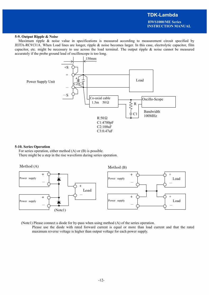
5-9. Output Ripple & Noise Maximum ripple & noise value in specifications is measured according to measurement circuit specified by
JEITA-RC9131A. When Load lines are longer, ripple & noise becomes larger. In this case, electrolytic capacitor, film capacitor, etc. might be necessary to use across the load terminal. The output ripple & noise cannot be measured accurately if the probe ground lead of oscilloscope is too long.
5-10. Series Operation
For series operation, either method (A) or (B) is possible. There might be a step in the rise waveform during series operation.
(Note1) Please connect a diode for by-pass when using method (A) of the series operation. Please use the diode with rated forward current is equal or more than load current and that the rated
maximum reverse voltage is higher than output voltage for each power supply.
C3
R:50Ω C1:4700pF C2:100uF C3:0.47uF
Bandwidth 100MHz
Co-axial cable 1.5m 50Ω
Oscillo-Scope R
C1
+S
+
-
-S
Power Supply Unit
+ Power supply -
+ Power supply -
+ Load -
+ Load -
+ Power supply -
+ Power supply - +
Load -
Method (A) Method (B)
(Note1)
C2 Load
150mm

-13-
TDK-Lambda HWS1000/ME Series INSTRUCTION MANUAL
5-11. Parallel Operation Current balancing function is provided. Either of operations mode (A) or (B) is possible.
(A)To Increase the Output Current Current balancing function activates by connecting PC-to-PC terminal and COM-to-COM terminal, and output current
of each power supply is equivalently supplied to load. Wires to PC terminals shall be as short as possible, same length and twisted.
There is a possibility that output could be unstable caused by external noise. For this case, disconnect COM terminal and connect -S terminal from parallel power supply to a single point on the load. Please refer connection Method (A)-2.
1. Adjust the output voltage of each power supply to be same value within 1% or 100mV, whichever is smaller. 2. Use same length and type of wires for all load lines. 3. Maximum value of output current in parallel is up to 80% of all paralleled models. The purpose of the current
balancing function is the static power-up. Therefore the output voltage might decrease according to the condition of dynamic load. There might be a step in the rise waveform during parallel operation.
4. Up to 5 units can be connected in parallel.
(B)To Use as a Backup Power Supply 1. Set power supply output voltage higher by the forward voltage drop of diode. 2. Adjust the output voltage of each power supply to be same value. 3. Use within the specifications for output voltage and output power.
Method (A)-1
PC
+S
+S
- S
- S PC
Load
Power Supply
COM
COM
Method (B) Power Supply
Load
Io Vf
Vf
Vo Vo+Vf
Vo+Vf
Output Power(W)=(Vo+Vf)× Io
+S
-S
+S
-S
PC
+S
+S
-S
-S PC
Load
Power Supply
COM
COM
Method (A)-2

-14-
TDK-Lambda HWS1000/ME Series INSTRUCTION MANUAL
5-12. Isolation Test Isolation resistance between output and E (chassis) shall be more than 100MW at 500VDC and between output and
CNT・PF shall be more than 10MW at 100VDC. For safety operation, voltage setting of DC isolation tester must be done before the test. Ensure that it is fully discharged after the test.
CNT TOG PF PC +S + - -S
E AC(L) AC(N)
Output - E (chassis) 500VDC 100MW or more CNT TOG PF
PC +S + - -S
E AC(L) AC(N)
Output - CNT・PF 100VDC 10MW or more
Isolation tester Isolation
tester

-15-
TDK-Lambda HWS1000/ME Series INSTRUCTION MANUAL
5-13. Withstand Voltage This series is designed to withstand 3.0kVAC between input and output, 2.0kVAC between input and E (chassis), 500VAC between output and E (chassis), and 100VAC between output and CNT・PF terminal each for 1 minute. When testing withstand voltage, set current limit of withstand voltage test equipment at 20mA. (Output-E (chassis) : 300mA, Output- CNT・PF : 100mA). The applied voltage must be gradually increased from zero to testing value and then gradually decreased for shut down. When timer is used, the power supply may be damaged by high impulse voltage at timer switch on and off. Connect input and output as follows. If output is left open during test, output voltage might appear momentarily. This product have monolithic ceramic capacitor in secondary circuit to frame ground. Some of the withstand voltage tester may generate high voltage at the matching with monolithic ceramic capacitor and may cause the unit damage. So, please check the waveform of test voltage.
Input - E (chassis) (solid line) 2kVAC 1min. (20mA) Input - Output (dotted line) 3kVAC 1min. (20mA)
Output - E (chassis) 500VAC 1min. (300mA)
Output - CNT・PF 100VAC 1min. (100mA)
~
CNT TOG PC +S + - -S
E AC(L) AC(N)
PF
Withstand Voltage Tester
~ CNT TOG PC +S + - -S
E AC(L) AC(N)
PF Withstand Voltage Tester
Withstand Voltage Tester
CNT TOG PF PC +S + - -S
E AC(L) AC(N)
~ ~

-16-
TDK-Lambda HWS1000/ME Series INSTRUCTION MANUAL
5-14. Output Voltage External Control (PV) (A) Control by External Voltage Output voltage external control function is provided. Output voltage can be varied by applying an external voltage (1 - 6V DC) to “PV” terminal and “COM” terminal. Note if an external voltage is not applied, there will be no output. Please consider the following characteristics below when operating the unit. Connection Method
Output Voltage Linearity
Note: Only as for the model of 24,36V output, the output voltage is used from 20% to 120% at the PV voltage is from 1V to 6.0 V
Note: Only as for the model of 48V output, the output voltage is used from 20% to 110% at the PV voltage is from 1V to 5.5V
Output Voltage Derating
Note: Only as for the type of 48V output, the maximum output voltage is used up to 110% at 90% load current.
* Output voltage usage below 20% is not a guaranteed. There is a possibility that it cannot be use with certain
product. Please conduct a thorough evaluation test before using it.
PV Voltage (Nominal Input Voltage)
20%
Nomina l Output
Voltage
Out
put (
V)
5V 1V 5 .5 V 6V 0
1 20% 1 10%
24,36V Model 48V Model
+S+
- -S
PV
Power Supply
Load
1-6V COM
Load Current 0
83% 90% 100%
Operatin g Area
20%
Nominal Output Voltage
Out
put (
V)
30%
120% 110%
24,36V Model 48V Model
3V Model

-17-
TDK-Lambda HWS1000/ME Series INSTRUCTION MANUAL
0%
20%
40%
60%
80%
100%
120%
0 10000 20000 30000 40000 50000
Variable resistor value for REF-PV(VR1) [Ω]
(B) Control by External Variable Resistor “PV” terminal and “COM” terminal usage is the same as explained in section 「control by external voltage」. But in this method voltage for control is supplied through REF terminal. Variable resistor is connected between REF terminal and COM terminal and the middle point of variable resistor is connected to PV terminal. Please use the output voltage within 20% - 120% of rated output voltage value (48V model : 20% - 110%). Wires for control lines must be as short as possible and use twisted wire or shield wire. In addition, maximum variable voltage when control by external variable resistor is rated output voltage (100%). When output voltage must be externally control to 120% of rated output voltage (110% for 48V model), please follow the following procedure. (1) PV terminal and REF terminal is short by using standard connector supplied. (2) Set the power supply output voltage to maximum value of the output voltage variable range mentioned in
specification standard by adjusting V.ADJ volume at the front panel. (3) Remove standard connector after input is cut off. (4) Connect external variable resistor (50kΩ) between REF terminal and COM terminal. Then connect middle point of
external variable resistor to PV terminal.(sensing current is 1.4mA) When output voltage is over rated value, please make sure that maximum output power is below rated value. Moreover, when output voltage is below rated value, please make sure that maximum output current is below rated value. Please consider the following characteristic during usage.
* Output voltage usage below 20% is not a guaranteed. There is a possibility that it cannot be use with certain
product. Please conduct a thorough evaluation test before using it.
+S
+
-
-S
REF
Power supply
Load
Sensing current : 1.4mA
Variable resistor 50kΩ
COM
PV VR1
Connection method
110% of maximum setting value
120% of maximum setting value
Rated output : voltage
Output voltage

-18-
TDK-Lambda HWS1000/ME Series INSTRUCTION MANUAL
5-15. Output peak Current For model with output peak current, please meet the following condition. Reduce peak current value according to output derating as section 6-1. The output is shut down by protection circuit when rated current and continuous peak output time (τ) exceeds rated value during usage.
When protection circuit is activated, input is temporarily cut off for a few minutes and then power is re-input or remote ON/OFF control signal should be input for recovery of the output.
Input voltage range :AC180V - 265V Continuous Peak output time.(τ) :Within 10 seconds Peak output current(Ip) :Within the rated peak output current
Duty:up to 35%
Duty = x 100(%)
Condition 1
Ip2× < Irms max
Condition 2
( Ip12× + a2 × ( 1- ) < Irms max
Ip,Ip1 Irms τ T
Model Irms max
HWS1000-24 34.6A
HWS1000-36 23.0A
HWS1000-48 17.2A
τ T
τ T
τ T
τ T
0A
Ip
τ T
0A
Ip1
τ T
aA
: Peak output current (A) : Effective current (A) : Peak current pulse width (sec) : cycle (sec)

-19-
TDK-Lambda HWS1000/ME Series INSTRUCTION MANUAL
6.Mounting Directions 6-1. Output Derating
Mounting directions are as follows. Standard mounting method is (A). Methods (B), (C), (D), (G) and (H) are also possible. Mounting methods besides (A),(B),(C),(D),(G) and (H) (example : (E) and (F)) are inhibit.
6-2.Mounting Method Caution (1) This Power supply unit is a forced air-cooling system with a built-in fan. (2) This power supply has ventilating holes on the front and back panels.
Keep these areas freely more than 100mm from front side and more than 50mm from rear side. (3) Please note that ventilation will be worsened in a dusty environment. (4) Built-in fan is limited life part, which require periodic replacement. (Replacement will be charge). (5) The ambient temperature of this power supply is less than 50mm from the center of a front side. (6) The maximum allowable penetration of mounting screw is 6mm. (7) Recommended torque for mounting screw (M4) is 1.27N・m.
Ta(°C) LOAD(%)
A, B, C, D, G, H -10 - +35 100
50 100 71 50
HWS1000 Output Derating
Fan motor
(Top:HWS1000)
More than50mm More than100mm
(Rear) (Front)
(D)
(A) Standard Mounting
(B) (C)
(E)Inhibit (F) Inhibit 100
- 10
80
60
40
20
0 0 20 40 50 60
Load (%)
Ambient Temperature ( ℃ ) 71
Mounting A,B,C,D,G,H
(G) (H)

-20-
TDK-Lambda HWS1000/ME Series INSTRUCTION MANUAL
7. Wiring Method (1) The output load line and input line shall be separated and twisted to improve noise sensitivity. (2) The sensing lines shall be twisted or shield wire and separated from the output lines. (3) Use all lines as thick and short as possible to make lower impedance. Wires are to be twisted or use shield wire to
improve noise sensitivity. (4) Attaching a capacitor to the load terminals can eliminate noise. (5) E terminal of this power supply is functional earthing. For safety purposes, connect protective earthing terminal to the
mounting set ground terminal. (6) Recommended torque for the terminal piece: (7) Recommended wiring
Recommended circuit protector : AC250V20A Recommended noise filter : RSEN-2020 (TDK-Lambda Corp.)
Input terminal (M4 screw) : 1.27 N・m Output terminal (M8 Bolt & Nut) : 10.8N・m
~
AC(L)
AC(N)
Noise Filter Circuit Protector
AC(L)
AC(N)
E
AC(L)
AC(N)
AC(L)
AC(N)
+
-
Load
HWS1000
Chassis of the equipment

-21-
TDK-Lambda HWS1000/ME Series INSTRUCTION MANUAL
(8) M4 screw for output terminal might damage the terminal’s inner thread. This is mainly cause by the M4 screw’s unthread section. Therefore, please select a washer, spring washer, etc. to avoid unthread screw section from penetrating into output terminal inner section.
8. External Fuse Rating
Refer to the following fuse rating when selecting the external fuses for input line. Surge current flows when line turns on. Use slow-blow fuse or time-lug fuse. Do not use fast-blow fuse. Fuse rating is specified by in-rush current value at line turn-on. Do not select the fuse according to input current (rms.) values under the actual load condition. HWS1000:20A 9. Troubleshooting Before concluding that the unit is at fault, make the following checks. (1) Check if the rated input voltage is apply. (2) Check if the wiring of input and output is correct. (3) Check if the I/O terminal connection is properly tighten by a regulated tightening torque. (4) Check if the wire material is not too thin. (5) Check if the output voltage control (V.ADJ) is properly adjusted. OVP might be triggered and output is cut off. (6) Check if the wiring of “+S” and “-S” terminal is correct. If in open condition, the stability and the accuracy of
the output deteriorate. (7) If use function of the remote ON/OFF control, check if the remote ON/OFF control connector is not opened.
If in open condition, output is cut off. (8) Check if the built-in fan is not stopped. Is fan stopped by something irregulars or dust, etc.
If fan stops, the PF signal is turn on. Moreover, the output is intercepted with the protection circuit if fan stops. Fans are the limited life parts. This power supply has ventilating holes on the front and back panels. Check if there is any irregulars or dust, etc.
(9) Is the main body of the power supply abnormally hot? Please turn on the input again after allowing the unit to cool down sufficiently. The output shut down by over temperature protection function.
(10) Check if the output current and output power is not applied over specification. (11) Check if the input voltage wave is sinusoidal. If this power supply unit is connected to a UPS, input voltage wave
might not be sinusoidal. An audible noise is emitted from the power supply unit. (12) Audible noise can be heard during Dynamic-Load operation.
Unthread section
Output terminal
○ ×
-22-
TDK-Lambda HWS1000/ME Series INSTRUCTION MANUAL
10. The life expectancy The life of the power supply depends on the life of the built-in aluminum electrolytic capacitor being used and mounted fan. Each life is described in reliability data. The life of the aluminum electrolytic capacitor varies depending on the method of mounting the power supply, the load current, and the ambient temperature. Please refer to "Electrolytic Capacitor Lifetime". The life of the fan depends on the fan intake or exhaust temperature. Please refer to "Fan Life Expectancy". Please do not use the product which passed over the life expectancy. There is a risk of unexpected output shutdown and specifications may not be satisfied. Please contact us for maintenance or exchange the product which passed over the life expectancy.
11. Warranty Period
This product is warranted for a period of 5 years from the date of shipment. For damages occurring at normal operation within this warranty period, repair is free of charge.
12. CE MARKING/UKCA MARKING
CE MARKING CE Marking, when applied to a product or packing material for a product covered by this handbook, indicates compliance with the Low Voltage Directive, EMC Directive and RoHS Directive. UKCA MARKING UKCA Marking, when applied to a product or packing material for a product covered by this handbook, indicates compliance with the Electrical Equipment (Safety) Regulations, Electromagnetic Compatibility Regulations and Restriction of the Use of Certain Hazardous Substances in Electrical & Electronic Equipment Regulations.
TDK-Lambda Corp. OFFICE : 2704-1 SETTAYA-MACHI, NAGAOKA-SHI, NIIGATA JAPAN
TEL +81-258-22-1234 FACSIMILE +81-258-22-1375