iag competition series air / oil separator (aos) for 2002 ... · iag competition series air / oil...
TRANSCRIPT

IAG Performance | 1203 Baltimore Blvd. Westminster, MD 21157 | Ph: 410-840-3555 | www.iagperformance.com 1
IAG Competition Series Air / Oil Separator (AOS) For 2002-07 WRX STI
Part# IAG-ENG-7200 Tools Required: Ratchet, torque wrench, extensions, needle nose pliers, hose cutter, snips/scissors, flat head screw driver, hose clamping pliers Sockets: 10mm, 12mm, 13mm, ¼” allen, Wrenches: 8mm, 10mm, 13mm, 19mm 11/16 ”, 3mm allen, Other: Electrical Tape Congratulations on the purchase of your Air/Oil Separator (AOS) and thank you for choosing IAG Performance. This installation manual is intended to guide you through the removal of the factory PCV system and the installation of the IAG AOS. If you already have an aftermarket catch can or AOS installed, please consult the specific instructions for your hardware to aid in its removal.
Parts List Part Name Quantity Notes Air/Oil Separator 1 Oil Drain Hose Assembly 1 24” Hose Length Top Coolant Hose Assembly 1 18” Hose Length, ½” I.D., -8ORB Bottom Coolant Hose Assembly 1 18” Hose Length, ½” I.D., -8ORB Discharge Hose 1 60” Hose Length, 1” ID Block Breather Hose 1 23” Hose Length, 5/8” ID Valve Cover Breather Hose 1 72” Hose Length, ½” ID Block Drain Replacement Hose 1 2” Hose Length, ¾” I.D. 5mm ID O-ring 1 7mm ID O-ring 1 Mounting Bracket 1 90° 5/8” Plastic Fitting 1 Block Breather Fitting PCV Replacement Fitting 1 Comp Series Upper Breather Fitting 1 Fasteners for Breather Top Fitting 2 M4x8mm AOS Drain Fitting 1 Comes preinstalled Spring Clamps 2 Coolant Hose Spring Clamps 6x10mm Bolt 3 6mm Washers 1 8mm Washer 1 ½” High Temp Rubber Cap 1 5/8” High Temp Rubber Cap 1 6” Zip Tie 16 11” Zip Tie 1 ¼” NPT Plug 1 For 2008+ Installs (Included in packaging) [Some parts used for 2007 STI install] 6mmx17mm Spacer 1 08+ Install (Also 2007 STI) 8mmx27mm Spacer 1 08+ Install Only
IAG Performance | 1203 Baltimore Blvd. Westminster, MD 21157 | Ph: 410-840-3555 | www.iagperformance.com 2
6x35mm Bolt 1 08+ Install Only 8x45mm Bolt 1 08+ Install Only Harness Relocation Bracket 1 08+ Install (Also 2007 STI) For 2002-07 Installs (Included in packaging) 6mmx29mm Spacer 1 02-07 Install Only 8mmx25mm Spacer 1 02-07 Install Only 6x45mm Bolt 1 02-07 Install Only 8x50mm Bolt 1 02-07 Install Only
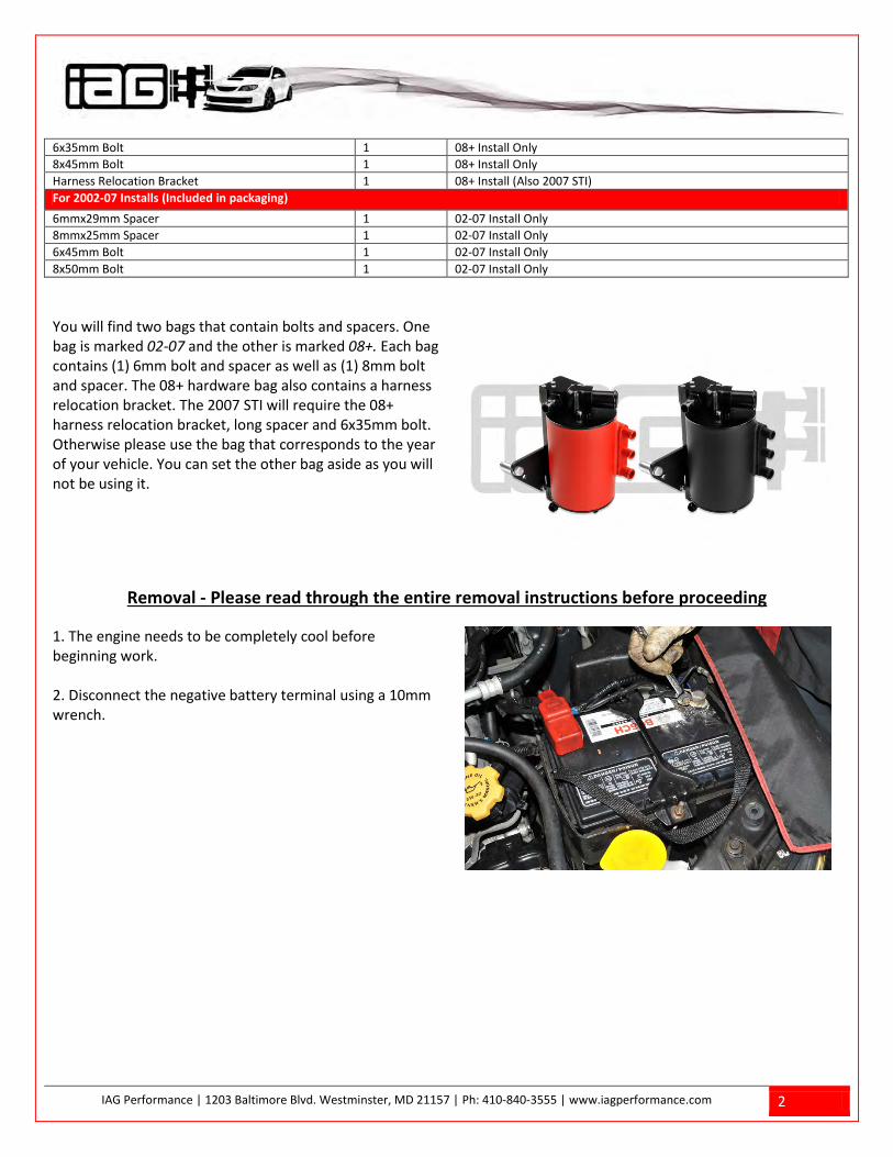
You will find two bags that contain bolts and spacers. One bag is marked 02-07 and the other is marked 08+. Each bag contains (1) 6mm bolt and spacer as well as (1) 8mm bolt and spacer. The 08+ hardware bag also contains a harness relocation bracket. The 2007 STI will require the 08+ harness relocation bracket, long spacer and 6x35mm bolt. Otherwise please use the bag that corresponds to the year of your vehicle. You can set the other bag aside as you will not be using it.
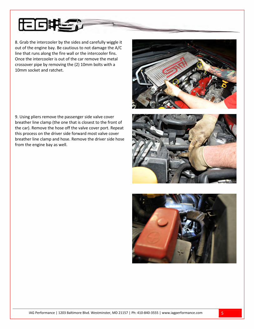
Removal - Please read through the entire removal instructions before proceeding 1. The engine needs to be completely cool before beginning work. 2. Disconnect the negative battery terminal using a 10mm wrench.

IAG Performance | 1203 Baltimore Blvd. Westminster, MD 21157 | Ph: 410-840-3555 | www.iagperformance.com 3
3. Remove the rubber breather hoses from the metal crossover pipe. There are two on the passenger side and one on the driver side.
4. Using a 12mm socket, remove the intercooler mounting bolts on either side of the intercooler.

IAG Performance | 1203 Baltimore Blvd. Westminster, MD 21157 | Ph: 410-840-3555 | www.iagperformance.com 4
5. Using a 12mm socket, remove the (2) 12mm bolts that hold the blow off valve (BOV) to the intercooler. You can leave the BOV where it sits. Be careful not to lose or damage the gasket.
6. Using a flat head screw driver, loosen the hose clamp on the turbo discharge silicone coupler.
7. Using a flat head screw driver, loosen the hose clamp at the intercooler outlet silicone coupler.
IAG Performance | 1203 Baltimore Blvd. Westminster, MD 21157 | Ph: 410-840-3555 | www.iagperformance.com 5
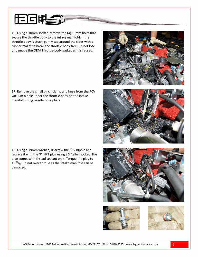
8. Grab the intercooler by the sides and carefully wiggle it out of the engine bay. Be cautious to not damage the A/C line that runs along the fire wall or the intercooler fins. Once the intercooler is out of the car remove the metal crossover pipe by removing the (2) 10mm bolts with a 10mm socket and ratchet.
9. Using pliers remove the passenger side valve cover breather line clamp (the one that is closest to the front of the car). Remove the hose off the valve cover port. Repeat this process on the driver side forward most valve cover breather line clamp and hose. Remove the driver side hose from the engine bay as well.

IAG Performance | 1203 Baltimore Blvd. Westminster, MD 21157 | Ph: 410-840-3555 | www.iagperformance.com 6
10. Remove the breather hose at the turbocharger inlet.
11. Using the supplied 5/8” vinyl cap, cover the hole in the inlet and secure it with a zip tie. Trim the excess of the zip tie with snips or scissors.

IAG Performance | 1203 Baltimore Blvd. Westminster, MD 21157 | Ph: 410-840-3555 | www.iagperformance.com 7
12. Remove the clamp from the OEM blow-by sensor located at the rear of the turbocharger inlet using a flat head screw driver. Then remove the small pinch clamp that holds the hose to the PCV valve using pliers.

IAG Performance | 1203 Baltimore Blvd. Westminster, MD 21157 | Ph: 410-840-3555 | www.iagperformance.com 8
13. Remove the PCV valve assembly from the engine. It may come out with the ¾” drain hose. If the OEM drain hose is in good condition you will reuse it. We have supplied you with a new drain hose if the OEM unit is worn or damaged.
14. Slide the supplied plastic drain fitting into the ¾” drain hose as shown.
15. Cap off the white portion of the blow-by sensor using the supplied ½” cap and zip tie as shown. Trim the excess off the zip tie.
IAG Performance | 1203 Baltimore Blvd. Westminster, MD 21157 | Ph: 410-840-3555 | www.iagperformance.com 9
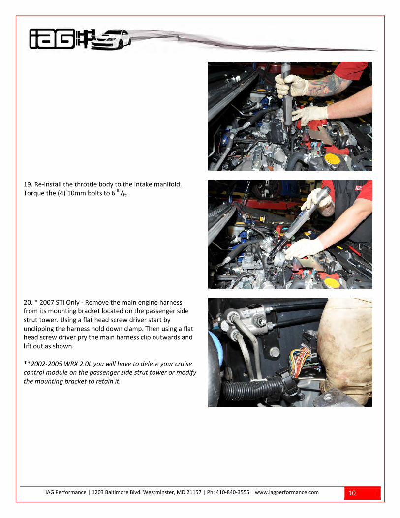
16. Using a 10mm socket, remove the (4) 10mm bolts that secure the throttle body to the intake manifold. If the throttle body is stuck, gently tap around the sides with a rubber mallet to break the throttle body free. Do not lose or damage the OEM Throttle-body gasket as it is reused.
17. Remove the small pinch clamp and hose from the PCV vacuum nipple under the throttle body on the intake manifold using needle nose pliers.
18. Using a 19mm wrench, unscrew the PCV nipple and replace it with the ¼” NPT plug using a ¼” allen socket. The plug comes with thread sealant on it. Torque the plug to 15 lb/ft. Do not over torque as the intake manifold can be damaged.
IAG Performance | 1203 Baltimore Blvd. Westminster, MD 21157 | Ph: 410-840-3555 | www.iagperformance.com 10
19. Re-install the throttle body to the intake manifold. Torque the (4) 10mm bolts to 6 lb/ft.
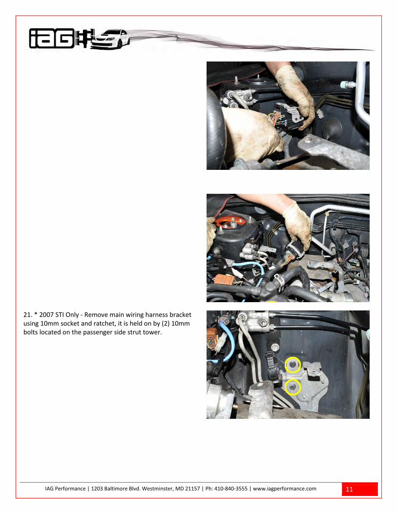
20. * 2007 STI Only - Remove the main engine harness from its mounting bracket located on the passenger side strut tower. Using a flat head screw driver start by unclipping the harness hold down clamp. Then using a flat head screw driver pry the main harness clip outwards and lift out as shown. **2002-2005 WRX 2.0L you will have to delete your cruise control module on the passenger side strut tower or modify the mounting bracket to retain it.
IAG Performance | 1203 Baltimore Blvd. Westminster, MD 21157 | Ph: 410-840-3555 | www.iagperformance.com 11
21. * 2007 STI Only - Remove main wiring harness bracket using 10mm socket and ratchet, it is held on by (2) 10mm bolts located on the passenger side strut tower.
IAG Performance | 1203 Baltimore Blvd. Westminster, MD 21157 | Ph: 410-840-3555 | www.iagperformance.com 12
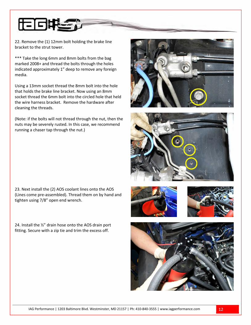
22. Remove the (1) 12mm bolt holding the brake line bracket to the strut tower. *** Take the long 6mm and 8mm bolts from the bag marked 2008+ and thread the bolts through the holes indicated approximately 1” deep to remove any foreign media. Using a 13mm socket thread the 8mm bolt into the hole that holds the brake line bracket. Now using an 8mm socket thread the 6mm bolt into the circled hole that held the wire harness bracket. Remove the hardware after cleaning the threads. (Note: if the bolts will not thread through the nut, then the nuts may be severely rusted. In this case, we recommend running a chaser tap through the nut.)
23. Next install the (2) AOS coolant lines onto the AOS (Lines come pre-assembled). Thread them on by hand and tighten using 7/8” open end wrench.
24. Install the ½” drain hose onto the AOS drain port fitting. Secure with a zip tie and trim the excess off.
IAG Performance | 1203 Baltimore Blvd. Westminster, MD 21157 | Ph: 410-840-3555 | www.iagperformance.com 13
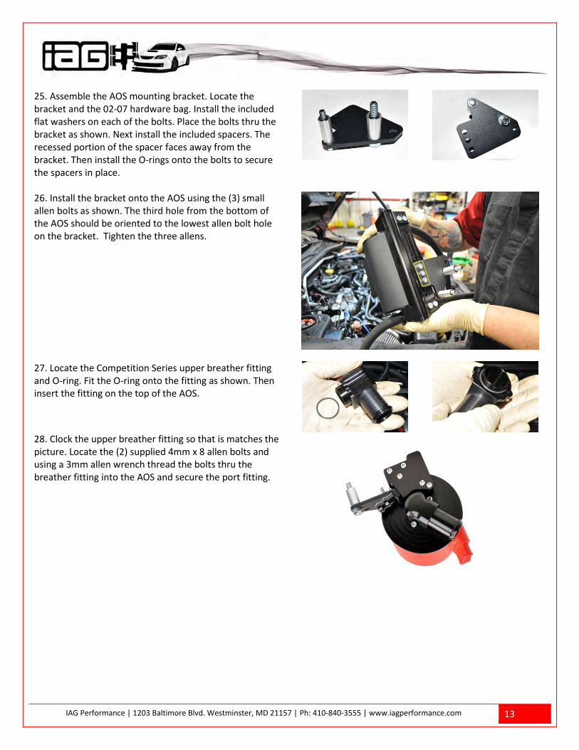
25. Assemble the AOS mounting bracket. Locate the bracket and the 02-07 hardware bag. Install the included flat washers on each of the bolts. Place the bolts thru the bracket as shown. Next install the included spacers. The recessed portion of the spacer faces away from the bracket. Then install the O-rings onto the bolts to secure the spacers in place.
26. Install the bracket onto the AOS using the (3) small allen bolts as shown. The third hole from the bottom of the AOS should be oriented to the lowest allen bolt hole on the bracket. Tighten the three allens.
27. Locate the Competition Series upper breather fitting and O-ring. Fit the O-ring onto the fitting as shown. Then insert the fitting on the top of the AOS.
28. Clock the upper breather fitting so that is matches the picture. Locate the (2) supplied 4mm x 8 allen bolts and using a 3mm allen wrench thread the bolts thru the breather fitting into the AOS and secure the port fitting.

IAG Performance | 1203 Baltimore Blvd. Westminster, MD 21157 | Ph: 410-840-3555 | www.iagperformance.com 14
29. * 2007 STI Only - you will require the harness relocation bracket, long spacer and 6x35mm bolt inside the 08+ hardware bag. Otherwise the 08+ bag is not used on the 2002-07 applications and can be placed aside.
29.A Press the relocation bracket into the 2007 STI harness. You may need to slightly pull the harness tab outward while inserting the bracket.
IAG Performance | 1203 Baltimore Blvd. Westminster, MD 21157 | Ph: 410-840-3555 | www.iagperformance.com 15
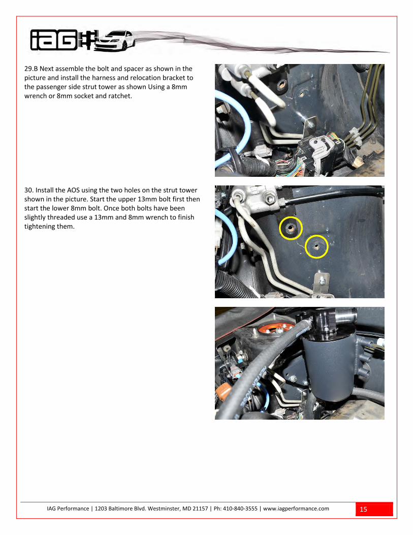
29.B Next assemble the bolt and spacer as shown in the picture and install the harness and relocation bracket to the passenger side strut tower as shown Using a 8mm wrench or 8mm socket and ratchet.
30. Install the AOS using the two holes on the strut tower shown in the picture. Start the upper 13mm bolt first then start the lower 8mm bolt. Once both bolts have been slightly threaded use a 13mm and 8mm wrench to finish tightening them.

IAG Performance | 1203 Baltimore Blvd. Westminster, MD 21157 | Ph: 410-840-3555 | www.iagperformance.com 16
31. To minimize coolant loss, pinch off the lower coolant hose that connects the turbo to the cylinder head using hose clamping pliers.
32. The IAG AOS coolant line will attach to the OEM coolant expansion tank. Trim the upper AOS coolant line to the correct length making sure when the line is routed there are not any kinks or obstructions. Once cut, using pliers pinch and slide the supplied pinch clamp onto the AOS coolant line.
33. Using pliers remove the OEM upper coolant expansion tank hose clamp. Pull the OEM expansion hose off and slide the new IAG AOS coolant hose on. Do this fast so that coolant loss is kept to a minimum. Then using pliers pinch and slide the new supplied pinch clamp over the expansion tank port barb to secure the line.
IAG Performance | 1203 Baltimore Blvd. Westminster, MD 21157 | Ph: 410-840-3555 | www.iagperformance.com 17
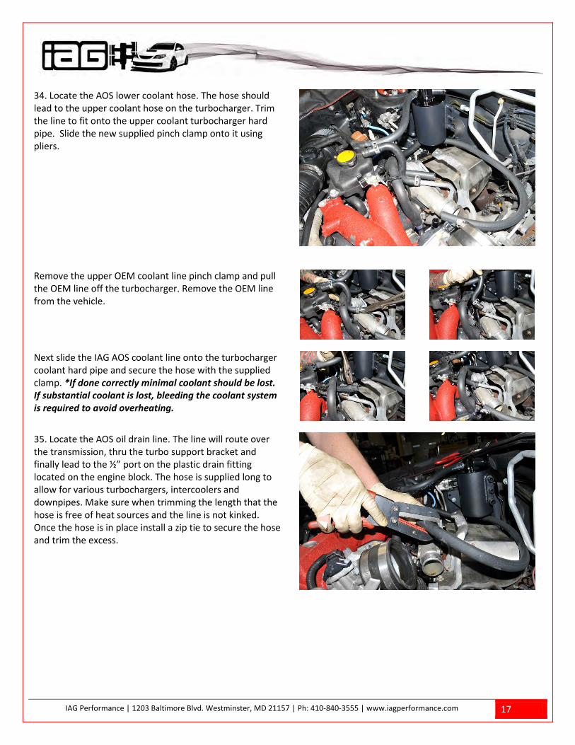
34. Locate the AOS lower coolant hose. The hose should lead to the upper coolant hose on the turbocharger. Trim the line to fit onto the upper coolant turbocharger hard pipe. Slide the new supplied pinch clamp onto it using pliers.
Remove the upper OEM coolant line pinch clamp and pull the OEM line off the turbocharger. Remove the OEM line from the vehicle.
Next slide the IAG AOS coolant line onto the turbocharger coolant hard pipe and secure the hose with the supplied clamp. *If done correctly minimal coolant should be lost. If substantial coolant is lost, bleeding the coolant system is required to avoid overheating.
35. Locate the AOS oil drain line. The line will route over the transmission, thru the turbo support bracket and finally lead to the ½” port on the plastic drain fitting located on the engine block. The hose is supplied long to allow for various turbochargers, intercoolers and downpipes. Make sure when trimming the length that the hose is free of heat sources and the line is not kinked. Once the hose is in place install a zip tie to secure the hose and trim the excess.
IAG Performance | 1203 Baltimore Blvd. Westminster, MD 21157 | Ph: 410-840-3555 | www.iagperformance.com 18
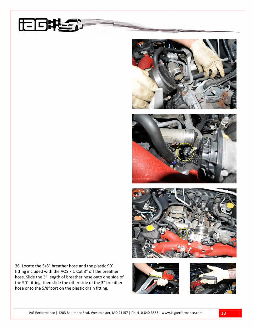
36. Locate the 5/8” breather hose and the plastic 90° fitting included with the AOS kit. Cut 3” off the breather hose. Slide the 3” length of breather hose onto one side of the 90° fitting, then slide the other side of the 3” breather hose onto the 5/8”port on the plastic drain fitting.
IAG Performance | 1203 Baltimore Blvd. Westminster, MD 21157 | Ph: 410-840-3555 | www.iagperformance.com 19
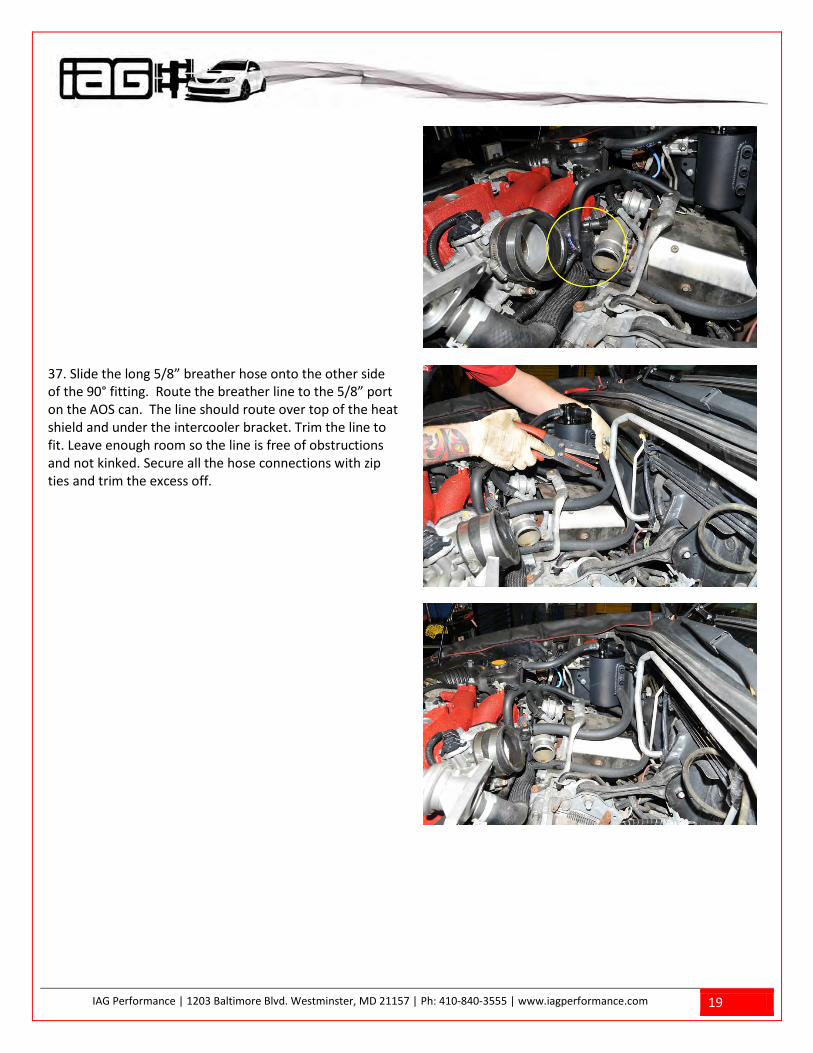
37. Slide the long 5/8” breather hose onto the other side of the 90° fitting. Route the breather line to the 5/8” port on the AOS can. The line should route over top of the heat shield and under the intercooler bracket. Trim the line to fit. Leave enough room so the line is free of obstructions and not kinked. Secure all the hose connections with zip ties and trim the excess off.
IAG Performance | 1203 Baltimore Blvd. Westminster, MD 21157 | Ph: 410-840-3555 | www.iagperformance.com 20
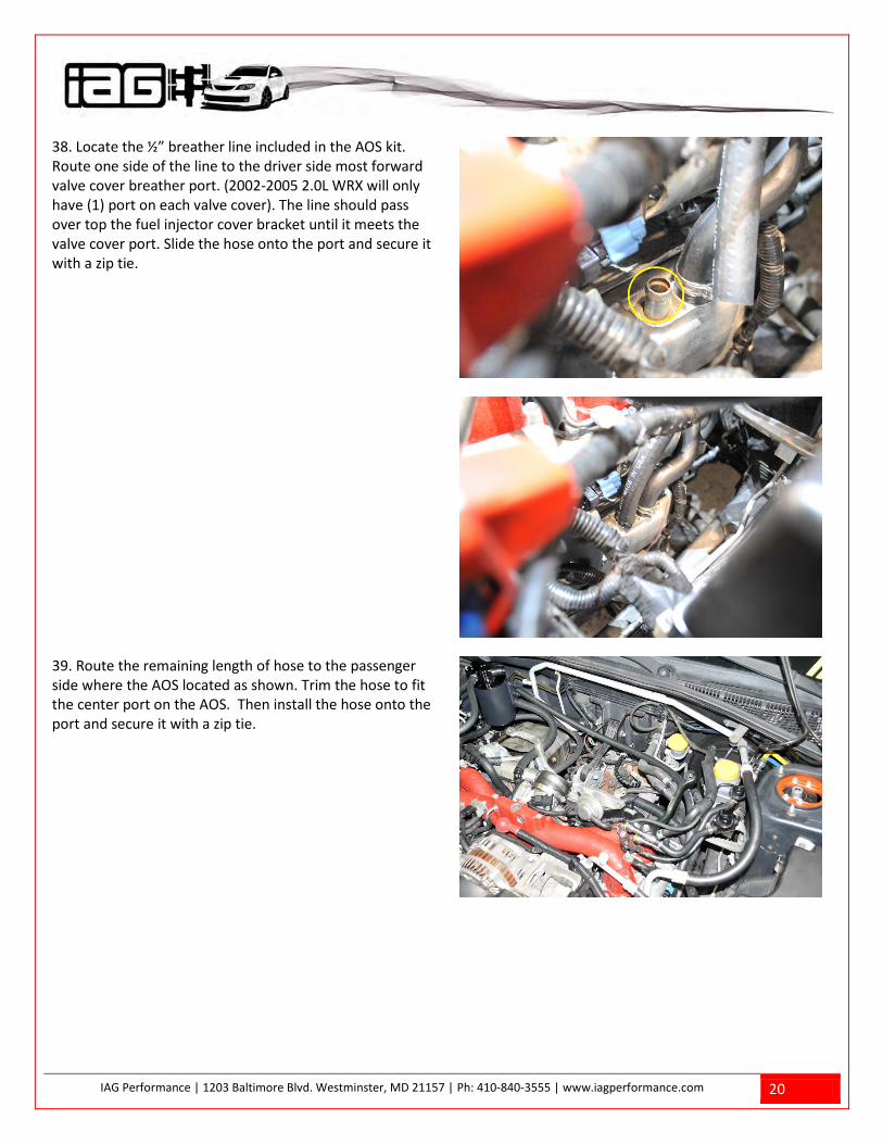
38. Locate the ½” breather line included in the AOS kit. Route one side of the line to the driver side most forward valve cover breather port. (2002-2005 2.0L WRX will only have (1) port on each valve cover). The line should pass over top the fuel injector cover bracket until it meets the valve cover port. Slide the hose onto the port and secure it with a zip tie.
39. Route the remaining length of hose to the passenger side where the AOS located as shown. Trim the hose to fit the center port on the AOS. Then install the hose onto the port and secure it with a zip tie.

IAG Performance | 1203 Baltimore Blvd. Westminster, MD 21157 | Ph: 410-840-3555 | www.iagperformance.com 21
40. Using the remaining length of ½” hose, route it over the top of the power steering lines and over top of the injector cover bracket. Finally slide it onto the passenger side valve cover breather port and secure it with a zip tie and trim the excess off.

IAG Performance | 1203 Baltimore Blvd. Westminster, MD 21157 | Ph: 410-840-3555 | www.iagperformance.com 22
Next route the remaining portion of the hose under the intercooler bracket and alongside the 5/8” breather hose. The line will then lead up to the upper AOS port. Make sure the line is free of kinks or any obstructions. Trim the line to fit and secure it with a zip tie trimming off the excess.

IAG Performance | 1203 Baltimore Blvd. Westminster, MD 21157 | Ph: 410-840-3555 | www.iagperformance.com 23
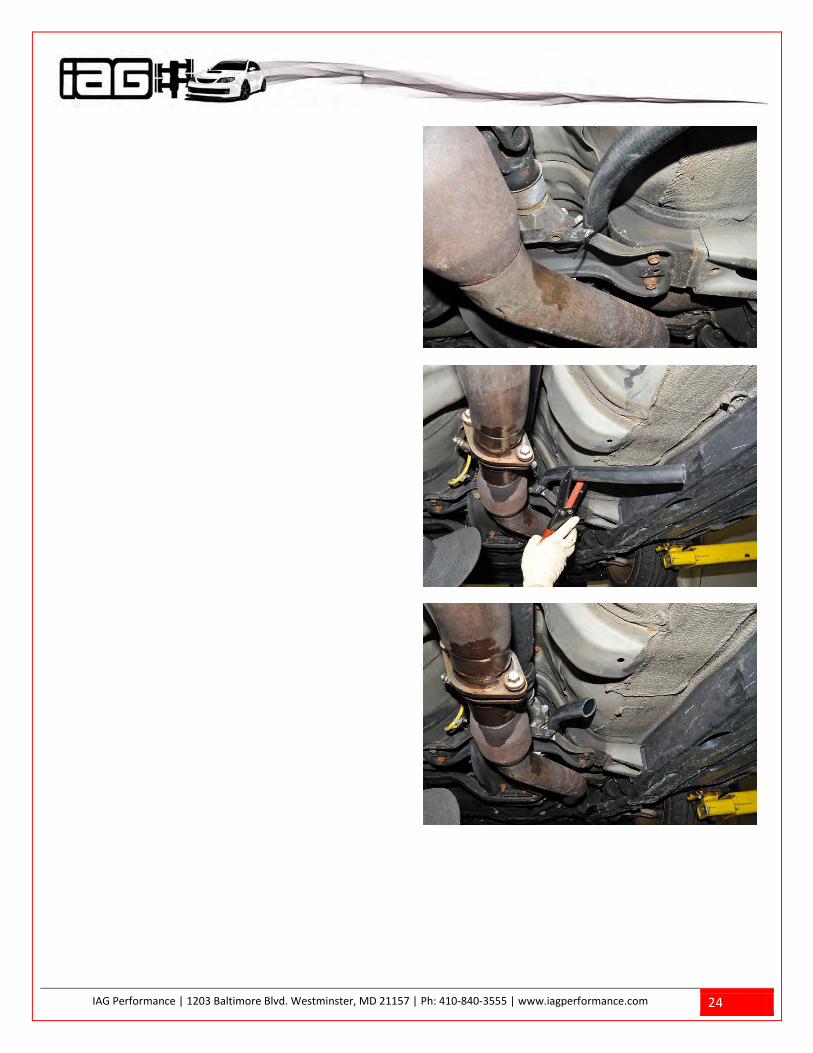
41. Locate the 1” breather line and route it down the passenger side transmission tunnel starting behind the firewall ac lines. Push the line down as far as it can go. You may need to get under the car to help guide the hose. Attach the upper portion of the line to the upper AOS breather port and secure it with a zip tie trimming the excess.
42. Place the vehicle on a lift or on jack stands, route the remainder of the 1” breather line overtop the transmission cross-member and along the side of the transmission. The line should rest on top of the center exhaust heat shield. Make sure the line is free of any kinks then secure the line using an 11” zip tie to the transmission cross member as shown. Snip the excess of the zip tie off. Trim approximately 6-8” of hose length off for road clearance.
IAG Performance | 1203 Baltimore Blvd. Westminster, MD 21157 | Ph: 410-840-3555 | www.iagperformance.com 24
IAG Performance | 1203 Baltimore Blvd. Westminster, MD 21157 | Ph: 410-840-3555 | www.iagperformance.com 25
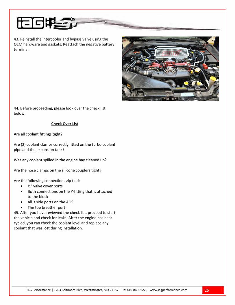
43. Reinstall the intercooler and bypass valve using the OEM hardware and gaskets. Reattach the negative battery terminal.
44. Before proceeding, please look over the check list below:
Check Over List
Are all coolant fittings tight? Are (2) coolant clamps correctly fitted on the turbo coolant pipe and the expansion tank? Was any coolant spilled in the engine bay cleaned up? Are the hose clamps on the silicone couplers tight? Are the following connections zip tied:
• ½” valve cover ports • Both connections on the Y-fitting that is attached
to the block • All 3 side ports on the AOS • The top breather port
45. After you have reviewed the check list, proceed to start the vehicle and check for leaks. After the engine has heat cycled, you can check the coolant level and replace any coolant that was lost during installation.