ieee transactions on power delivery 1 stability · pdf filestability modeling and comparative...
TRANSCRIPT

IEEE TRANSACTIONS ON POWER DELIVERY 1
Stability Modeling and Comparative Study of SeriesVectorial Compensators
J. Miguel Gonzalez, Student Member, IEEE, Claudio A. Canizares, Fellow, IEEE,and Juan M. Ramırez, Member, IEEE
Abstract—Complete stability analyses, including voltage, smallperturbation and transient stability studies, and the associatedmodels and controls of a Series Vectorial Compensator (SVeC)are presented in this paper. A full comparative evaluation of thiscontroller with respect to controllers used mainly for oscillationcontrol in transmission corridors, namely, Thyristor-ControlledSeries Capacitors (TCSC) and Series Static Synchronous Com-pensators (SSSC), is presented for the first time. The IEEE 14-bus benchmark system and a 190-bus, 46-machine model of theMexican grid are used for illustrative and comparison purposes.The results obtained show that the SVeC has better oscillationdamping characteristics than the TCSC and SSSC, hence makingthese types of controllers a competitive alternative against existingseries Flexible AC Transmission System (FACTS) controllers fordynamic series compensation of transmission lines, especiallywhere space and cost are an issue.
Index Terms—Flexible AC Transmission System (FACTS),Series Vectorial Compensator (SVeC), Series Static SynchronousCompensator (SSSC), Thyristor-Controlled Series Capacitor(TCSC), voltage stability, small-perturbation stability, transientstability, power oscillation control, Hopf bifurcations.
I. GLOSSARY OF TERMS
DAE: Differential Algebraic Equations.FACTS: Flexible AC Transmission Systems.HB: Hopf bifurcation.ODAE: Ordinary Differential Algebraic EquationsPOD: Power Oscillation Damping.PSS: Power System Stabilizer.PWM: Pulse Width Modulation.TCSC: Thyristor-Controlled Series Capacitor.TCR: Thyristor-Controlled Reactor.SVeC: Series Vectorial Compensator.SSSC: Series Static Synchronous Compensator.STATCOM: Shunt Static Synchronous Compensator.SVC: Static Var Compensator.UPFC: Unified Power Flow Controller.VSC: Voltage-Sourced Converter.
II. INTRODUCTION
This paper was submitted on November 2008. Revised and resubmitted onApril 2009. Accepted May 2009.
This work was supported by CONACyT, Mexico and the Natural Sciencesand Engineering Research Council (NSERC) of Canada.
Juan Miguel Gonzalez and Juan Manuel Ramirez are with CINVESTAV,Guadalajara, Jalisco, CP 45010, Mexico (email: [email protected]).
Claudio A. Canizares is with the Department of Electrical and ComputerEngineering, University of Waterloo, Waterloo, ON, N2L 3G1, Canada(email:[email protected]).
POWER systems are currently operating closer to theirstatic and dynamic stability limits due to an increase in
the power transfer demands on existing transmission systems,given the significant growth of loads and generation, lackof new transmission lines, and competitive electricity marketpressures. Stability problems associated with voltage collapseand undamped oscillations are currently the leading causesof major blackouts (e.g. [1], [2]). In this context, FACTScontrollers are becoming more relevant, since due to theirfast response, these controllers can improve the stability of apower system, thereby allowing a more efficient use of existingtransmission grids [3].
Various types of FACTS controllers, particularly SVCs,TCSCs, STATCOMs, SSSCs and UPFCs are being used inpractice [3]–[7], some more than others; for example, in Brazil,TCSCs are used as an alternative to PSSs for the control ofinter-area power oscillations in a North-South interconnection[8]. These controllers are based on thyristors or VSC-basedconverters. However, more recently, new controllers basedon ac-ac vectorial converters have been proposed [9]–[14],demonstrating that it is possible to attain similar controlobjectives and performance as those based on VSC converters;in all these papers, as opposed to the present paper, detailedswitching models rather than stability models of the vectorialconverters are used for simulation purposes. Thus, in [9], theauthors discuss the use of an SVeC to control active power ona transmission line with a simple structure, injecting a seriescapacitive reactance that is adjusted automatically through aduty cycle control. A brief comparison of the SVeC withrespect to a TCSC is presented in [10] on a small radial powersystem with three buses, a generator and a load, showingthat the SVeC presents a smoother control alternative than theTCSC during transients, since the TCSC is designed to “jump”from capacitive to inductive operating regions in transientoperating conditions to avoid open-circuit operation and toreduce harmonics [15].
A comparative evaluation between the SVeC and an SSSCis presented in [14], based on detailed switching models anda single generator-infinite bus (SIB) test system, showingthat the dc-link requires about twice as much capacitiveenergy storage and about 66% additional semiconductor MVArating for the same application. No practical SVeC has beenbuilt and installed on a real transmission system thus far;however, a comparative estimate of components’ costs forthese two controllers is presented in [14], based on publiclyavailable information regarding costs of transformers andcapacitors, and power-semiconductor manufacturers’ quotes.
IEEE TRANSACTIONS ON POWER DELIVERY 2
The aforementioned paper shows that the cost of the SSSCis higher than the SVeC, with the latter presenting higherlosses. It is also mentioned that the SVeC can operate at highertemperatures due to the use of ac capacitors as opposed to thedc capacitors used in the SSSC, which are quite vulnerable tohigh temperatures. Finally, it is argued that another advantageof the SVeC’s converter topology is its more compact sizecompared to the SSSC’s VSC converter. Similar argumentsare presented in [16] and [17].
Based on the aforementioned comparisons, it can be arguedthat direct PWM, vectorial-converter-based controllers may bea reasonable alternative to thyristor- and VSC-based optionsfor similar applications. Therefore, it is necessary to performfurther comparative studies between converter technologies forthe same power system applications to determine all possibleSVeC’s advantages and disadvantages with respect to TCSCand SSSC series controllers; this is the main focus of thepresent paper. Thus, this paper concentrates on performingdetailed comparative voltage, transient and oscillatory stabilitystudies, as well as proposing and discussing the required SVeCmodels and controls for these types of studies, consideringthis controller’s application and performance in multi-machinepower systems.
The current authors have presented in [18]–[20] somestudies of the effect of an SVeC on power system stability.Thus, the controller steady-state performance is analyzed in[18], based on a power flow model of the SVeC. Some transientstability studies are discussed in [19] and [20], based ona somewhat complex stability model and a simple controlapproach for active power regulation; in these papers, it isshown that the controller does not provide enough dampingfor certain contingencies. Based on these preliminary studies,besides the comparative studies with respect to TCSCs andSSSCs for overall stability improvement presented here, abetter and simpler stability model and POD control for theSVeC is proposed and studied in the present paper.
The rest of the paper is structured as follows: Section IIIexplains briefly the basic background theory behind the modelsand analysis approach used in the current paper, presentinga brief discussion of DAE power system models, small-perturbation stability studies and HBs. Previously proposedand widely used TCSC and SSSC stability models and theircontrols, including POD controls, are presented and discussedin this section as well. Section IV describes in detail theproposed SVeC stability model and its controls. Completestability studies and associated results obtained for the IEEE14-bus benchmark system and a 190-bus, 46-machine model ofthe Mexican power system, including the 3 different FACTScontrollers under study, are shown and discussed in SectionV. A summary and the main contributions of the paper arepresented in Section VI.
III. BACKGROUND
A. Small-perturbation Analysis and P-V curves
In general, power systems are modeled using a set of DAEequations as follows:
x = f (x, y, λ, p) (1)
Imaginary
RealHopf
Bifurcation
λ
λ
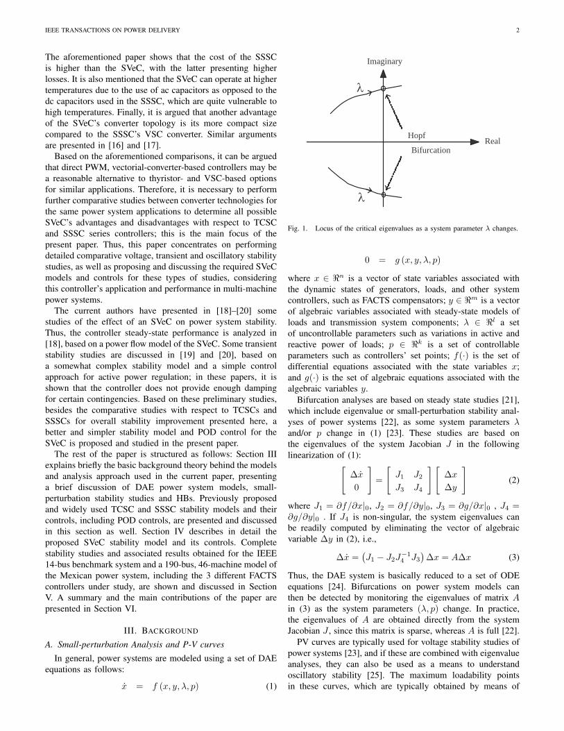
Fig. 1. Locus of the critical eigenvalues as a system parameter λ changes.
0 = g (x, y, λ, p)
where x ∈ <n is a vector of state variables associated withthe dynamic states of generators, loads, and other systemcontrollers, such as FACTS compensators; y ∈ <m is a vectorof algebraic variables associated with steady-state models ofloads and transmission system components; λ ∈ <l a setof uncontrollable parameters such as variations in active andreactive power of loads; p ∈ <k is a set of controllableparameters such as controllers’ set points; f(·) is the set ofdifferential equations associated with the state variables x;and g(·) is the set of algebraic equations associated with thealgebraic variables y.
Bifurcation analyses are based on steady state studies [21],which include eigenvalue or small-perturbation stability anal-yses of power systems [22], as some system parameters λand/or p change in (1) [23]. These studies are based onthe eigenvalues of the system Jacobian J in the followinglinearization of (1):[
∆x
0
]=
[J1 J2
J3 J4
] [∆x
∆y
](2)
where J1 = ∂f/∂x|0, J2 = ∂f/∂y|0, J3 = ∂g/∂x|0 , J4 =∂g/∂y|0 . If J4 is non-singular, the system eigenvalues canbe readily computed by eliminating the vector of algebraicvariable ∆y in (2), i.e.,
∆x =(J1 − J2J
−14 J3
)∆x = A∆x (3)
Thus, the DAE system is basically reduced to a set of ODEequations [24]. Bifurcations on power system models canthen be detected by monitoring the eigenvalues of matrix Ain (3) as the system parameters (λ, p) change. In practice,the eigenvalues of A are obtained directly from the systemJacobian J , since this matrix is sparse, whereas A is full [22].
PV curves are typically used for voltage stability studies ofpower systems [23], and if these are combined with eigenvalueanalyses, they can also be used as a means to understandoscillatory stability [25]. The maximum loadability pointsin these curves, which are typically obtained by means of

IEEE TRANSACTIONS ON POWER DELIVERY 3
kV mV
sV
kmI
jX
C
θk θm
dc-ac converter VSC
km
Fig. 2. SSSC single-line diagram.
kmP
refP PK0sV
PODv
11rT s +
sV
maxsV
minsV
IKs 1sV
rK
Fig. 3. SSSC power regulator.
continuation power flows, can be associated with voltagecollapse instabilities.
In general, voltage collapse and oscillatory phenomenahave been associated with bifurcation phenomena in nonlinearsystems. Therefore, bifurcation theory has been used in, forexample, [25]–[29] to study oscillation problems and designcorrective controls for damping these oscillations in powersystems; in these papers, HBs are linked to oscillatory insta-bilities.
HBs are characterized by periodic orbits emerging aroundan equilibrium point [21], and can be studied with the helpof eigenvalue analyses. At a HB point, the system model (1)presents a pair of purely imaginary eigenvalues of the statematrix A in (3) as the (λ, p) parameters change [25]; thus, thepoint where a complex conjugate pair of eigenvalues cross theimaginary axis as the system parameters λ and/or p change isknown as a HB point, as illustrated in Fig.1.
Since, as mentioned above, HBs can be associated withsmall active power oscillations in power systems [25]–[29],series-connected FACTS controllers with active power controlshave been proposed and are being used for the control of inter-area oscillations [3], [8], [15]. Hence, the following sectionsconcentrate on describing and discussing typical active powerlinear controls used for damping small power oscillations inthese types of FACTS controllers, i.e. SSSC, TCSC and SVeC.
1w
ww
T sKT s+
PODv
maxPODv
minPODv
kmP1
2
11
T sT s
++
3
4
11
T sT s
++
11T s∈ +
1v 2v 3v
Fig. 4. POD control block diagram.
mV
-jX
TCSCjXkV θk θm
C
jXL
jXkm
Fig. 5. TCSC single-line diagram.
B. SSSC Model and Controls
The SSSC is based on a VSC device that injects a voltage inseries with the transmission line. The transient stability modelused in this paper is extracted from [30], where the SSSC isrepresented by a series-connected voltage phasor source VS ,as depicted in Fig.2, which is always kept in quadrature withthe line current phasor Ikm, so that the SSSC can exchangeonly reactive power with the system. Thus, the controllableparameter in this case is the magnitude VS , which is used toregulate active power flow. This model yields the followingalgebraic power flow equations between the k and m nodesin Fig.2:
Pkm = (1 + Ψ)VkVmBkm sin (θk − θm) (4)Pmk = − Pkm
Qkm = (1 + Ψ)VkBkm [Vk − Vm cos (θk − θm)]Qmk = (1 + Ψ)VmBkm [Vm − Vk cos (θk − θm)]
where Ψ = Vs/√
V 2k + V 2
m − 2VkVm cos (θk − θm), andVk∠θk, Vm∠θm, and Bkm = 1/Xkm are defined in Fig.2.
The basic control strategy in Fig.3 is adopted here to regu-late the active power flow. Since the main aim of this SSSCmodel is to control the active power through the transmissionline where is embedded, a vPOD input signal is used in itscontrol to damp power oscillations. This signal comes fromthe POD control depicted in Fig.4, which basically has thesame control structure as a typical PSS [22].
C. TCSC Model and Control
The TCSC transient stability model used here is extractedfrom [31], and corresponds to a typical TCSC controller basedon a TCR in parallel with a bank of capacitors, as depictedin Fig.5. The TCSC can be adequately represented in stabilitystudies by an equivalent reactance XTCSC , the value of which

IEEE TRANSACTIONS ON POWER DELIVERY 4
kmP
refP
PODv
11rT s +
0α ( )B αB
minα
maxαrK
PK
IKs 2x
cx
Fig. 6. TCSC power regulator.
A
B
C
aT
bT
cT
aC
bC
cC
'aS
'bS'cS
aS
bS
cS
Series injectiontransformer
Transmission Line
Fig. 7. Transmission line with PWM SVeC.
is adjusted automatically to regulate the power flow throughthe transmission line. The variable equivalent reactance of theTCSC controller is allowed to change in either the inductiveor the capacitive regions, avoiding the resonance region.
The algebraic equations for the power flows between thek and m nodes associated with this model are the same asthose presented in (4), where all phasor voltages are definedin Fig.5. Here, Ψ is function of the thyristors’ firing angle [31]as follows:
Ψ(α)=B(α)Bkm
(5)
where:
B(α)=π
(k4
x − 2k2x + 1
)cos[kx (π − α)]
Xden(6)
Xden=XC cos[kx (π − α)] (7)(πk4
x − π − 2k4xα + 2k2
xα− k4x sin(2α))
+XC cos[kx (π − α)](k2
x sin(2α)− 4k2x cos(α) sin(α)
)−XC
[4k3
x cos2(α) sin[kx(π − α)]]
and kx =√
XC/XL. Note that XTCSC max corresponds toαmax, and similarly for the relationship between XTCSC min
and αmin.The control strategy depicted in Fig.6 is used here, where
B(α) is defined in (6). As is typical in TCSC controllers, thepower oscillation damping control illustrated in Fig.4 is alsoincluded.
sVkmP
1:1 sD−
kV θk mV θmSVeCjX
kmjX
n:1
Ac link MatrixconverterS'abc Sabc
c-jX
Fig. 8. SVeC single-line diagram.
( )B
Dmaxs
Dmins
Ds
kmP
refP
PODv
11rT s +
0sD B
rK
PK
IKs 2'x
'cx
Fig. 9. SVeC power regulator.
IV. SERIES VECTORIAL COMPENSATOR
A. Description
The schematics of the SVeC are shown in Fig.7 [10]. Theseries compensator consists of: series injection transformersTa, Tb and Tc; compensation capacitors Ca, Cb and Cc; andPWM-controlled switches Sa, Sb, Sc, S′
a, S′b, and S′
c. Duringthe period when the switches Sa, Sb, and Sc are closed, thecompensation capacitors are connected. The switches S′
a, S′b,
and S′c operate complementarily with respect to Sa, Sb, and
Sc, thus avoiding the short-circuiting of the capacitor. In Fig.8,the single-line diagram associated with Fig.7 is depicted; here,the switches Sa, Sb, Sc, S′
a, S′b, and S′
c are represented by Sabc
and S′abc, respectively.
The main differences between the SVeC and the TCSC andSSSC controllers are the following:
• Protection: In the case of sudden surges, low-pass filtersin the SSSC and SVeC help with blocking high fre-quency voltages and currents associated with the surge.In addition to these filters, the switches are protectedagainst large surges with Metal Oxide Varistors (MOVs).Furthermore, to protect these controllers against over-currents due to nearby short circuits, the controls aredesigned to drive the output voltage towards zero inmicroseconds, so that the power in the controllers duringthe faults are practically zero, in spite of the high currents.In the case of the TCSC, it is necessary to wait for thenext current zero crossing to initiate control action.

IEEE TRANSACTIONS ON POWER DELIVERY 5
• Number of Switches: For the minimal three-phase config-uration, the TCSC requires six thyristors, while the SSSCand SVeC each need six IGBTs/GTOs, for an optimizedSVeC configuration based on two switches per phase asshown in Fig.7.
• Controls: To modify the firing angle of the thyristors,the TCSC requires several milliseconds, due to the needfor current zero crossings. On the other hand, the SSSCand SVeC controllers can change the switches’ duty cyclein hundreds of microseconds; however, a response delaycan be introduced through filters. Furthermore, for PWMcontrol, the SSSC requires a synchronous type PWM,which is not the case for the SVeC; this leads to a greatercomplexity in the SSSC control infrastructure.
The compensator basically provides a variable series reac-tance XSV eC adjusted through variations of the duty cycle Ds.As in the case of the SSSC and TCSC discussed above, thiscontroller is assumed to control the power flow in the line bymeans of varying its equivalent reactance XSV eC through thecontrol illustrated in Fig.9, as explained in more detail below.
B. Model and Control
As briefly discussed in Section II, the authors present in[18]–[20] some preliminary steady-state and transient stabilitystudies of the SVeC. In these papers, the models used arebased on complex equations that lead to some convergenceproblems during the numerical studies. Furthermore, a simplePI controller is used in these papers to control the active powerthrough the transmission line, which does not provide ade-quate damping for all power oscillations triggered by systemcontingencies. Therefore, a simpler stability model that doesnot present numerical problems is used here, together withthe improved control shown in Fig.9 for the regulation andoscillation damping of the transmission line’s active power.
From Fig.8, the equivalent impedance between the sendingand receiving end of the SVeC-transmission-line system canbe defined as:
Xeq = Xkm + XSV eC (8)
where, from [10]:
XSV eC = −n2 (1−Ds)2Xc (9)
Observe in (8) and (9) that the effective impedance de-pends on the duty cycle Ds of the switches; hence, thisduty cycle provides a means of realizing the desired powerflow control, as depicted in Fig.9. Notice in this figure that,following a similar transient stability modeling approach asin the case of the TCSC, the susceptance B = Bkm–Beq =1/Xkm–1/ (Xkm + XSV eC) is assumed to be controlled ei-ther directly or indirectly through the duty cycle Ds, and thevPOD signal comes from the same POD control depicted inFig.4.
The voltage phasor on the primary (transmission-line) sideof the coupling transformer in Fig.8 may be calculated asfollows:
Vs = n2 (1−Ds)2 Ikm (10)
1
2
3
4
5
67 8
910
11
12
13
14
C
C
C
C
GENERATORS
SYNCHRONOUSCOMPENSATORS
9
7
8
4
THREE WINDINGTRANSFORMER EQUIVALENT
Fig. 10. IEEE 14-bus benchmark test system.
Observe in (8)-(10) that all the quantities are at their maximumvalue when the duty cycle is zero. Hence, the operating pointat minimum duty cycle determines the rating of the converterelements, including the MVA rating of the transformer.
The equations for the power flows associated to the nodesk and m are as follows:
Pkm=VkVm (Bkm + B) sin (θk − θm) (11)Pmk=−Pkm
Qkm=V 2k (Bkm + B)− VkVm (Bkm + B) cos (θk − θm)
Qmk=V 2m (Bkm + B)− VkVm (Bkm + B) cos (θk − θm)
where, from Fig.9:
B (Ds) = − n2 (1−Ds)2Xc
Xkm
[Xkm − n2 (1−Ds)
2Xc
] (12)
Note that this model is much simpler to that proposed in [18]–[20]. From (9), XSV eC min = −n2Xc, and XSV eC max = 0,since Ds max = 1 and Ds min = 0.
V. RESULTS
This section presents and discusses the results obtained fromthe application of the aforementioned FACTS series controllersfor oscillation control to the IEEE 14-bus benchmark systemand a 190-bus realistic equivalent of the Mexican power grid.All presented results were obtained with the help of PSAT[31].
A. IEEE 14-bus Test System
A single-line diagram of the IEEE 14-bus benchmark sys-tem described in [31] is shown in Fig.10. It consists of5 generators, three of which are synchronous compensatorsused only for reactive power support, all modeled usingsubtransient stability models and IEEE Type 1 exciters andvoltage regulators; 3 transformers; 14 buses; 21 lines; and
IEEE TRANSACTIONS ON POWER DELIVERY 6
1 1.1 1.2 1.3 1.4 1.5 1.6 1.7 1.80
0.2
0.4
0.6
0.8
1
1.2
Loading Parameter λ (p.u.)
VB
us 1
4 in
p.u.
Base CaseOutage of Line 2−4Operating Point HB1
HB2
Fig. 11. PV curves for the 14-bus test system.
−9 −8 −7 −6 −5 −4 −3 −2 −1 0−10
−8
−6
−4
−2
0
2
4
6
8
10
Real
Imag
Critical Eigenvalues
Fig. 12. Eigenvalues for the 14-bus test system for a Line 2-4 outage atλ = 1.4 p.u.
1 1.1 1.2 1.3 1.4 1.5 1.6 1.7 1.80
0.2
0.4
0.6
0.8
1
1.2
Loading Parameter λ (p.u.)
VB
us 1
4 (p
.u.)
Base CaseOutage of Line 2−4Operating Point
HB: SSSC&TCSC
HB: SVeC
SNB: SSSC, TCSC & SVeC
Fig. 13. PV curves for the 14-bus test system with FACTS.
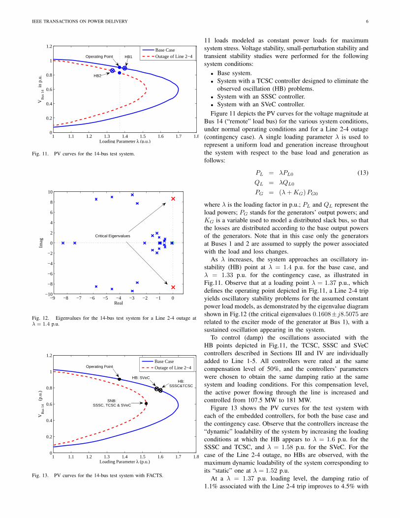
11 loads modeled as constant power loads for maximumsystem stress. Voltage stability, small-perturbation stability andtransient stability studies were performed for the followingsystem conditions:
• Base system.• System with a TCSC controller designed to eliminate the
observed oscillation (HB) problems.• System with an SSSC controller.• System with an SVeC controller.Figure 11 depicts the PV curves for the voltage magnitude at
Bus 14 (“remote” load bus) for the various system conditions,under normal operating conditions and for a Line 2-4 outage(contingency case). A single loading parameter λ is used torepresent a uniform load and generation increase throughoutthe system with respect to the base load and generation asfollows:
PL = λPL0 (13)QL = λQL0
PG = (λ + KG)PG0
where λ is the loading factor in p.u.; PL and QL represent theload powers; PG stands for the generators’ output powers; andKG is a variable used to model a distributed slack bus, so thatthe losses are distributed according to the base output powersof the generators. Note that in this case only the generatorsat Buses 1 and 2 are assumed to supply the power associatedwith the load and loss changes.
As λ increases, the system approaches an oscillatory in-stability (HB) point at λ = 1.4 p.u. for the base case, andλ = 1.33 p.u. for the contingency case, as illustrated inFig.11. Observe that at a loading point λ = 1.37 p.u., whichdefines the operating point depicted in Fig.11, a Line 2-4 tripyields oscillatory stability problems for the assumed constantpower load models, as demonstrated by the eigenvalue diagramshown in Fig.12 (the critical eigenvalues 0.1608±j8.5075 arerelated to the exciter mode of the generator at Bus 1), with asustained oscillation appearing in the system.
To control (damp) the oscillations associated with theHB points depicted in Fig.11, the TCSC, SSSC and SVeCcontrollers described in Sections III and IV are individuallyadded to Line 1-5. All controllers were rated at the samecompensation level of 50%, and the controllers’ parameterswere chosen to obtain the same damping ratio at the samesystem and loading conditions. For this compensation level,the active power flowing through the line is increased andcontrolled from 107.5 MW to 181 MW.
Figure 13 shows the PV curves for the test system witheach of the embedded controllers, for both the base case andthe contingency case. Observe that the controllers increase the“dynamic” loadability of the system by increasing the loadingconditions at which the HB appears to λ = 1.6 p.u. for theSSSC and TCSC, and λ = 1.58 p.u. for the SVeC. For thecase of the Line 2-4 outage, no HBs are observed, with themaximum dynamic loadability of the system corresponding toits “static” one at λ = 1.52 p.u.
At a λ = 1.37 p.u. loading level, the damping ratio of1.1% associated with the Line 2-4 trip improves to 4.5% with

IEEE TRANSACTIONS ON POWER DELIVERY 7
0 2 4 6 8 10 12 14 16 18 20
0.999
0.9995
1
1.0005
Time (s)
ωG
en (
p.u.
)
G1
G2
Fig. 14. Generators speed oscillation due to a Line 2-4 trip at λ = 1.37p.u. for the 14-bus test system.
0 5 10 15 200.9998
0.9999
1
1.0001
1.0002
Time (s)
ωG
en (
p.u.
)
G1
G2
Fig. 15. Generators speed oscillation due to a Line 2-4 trip at λ = 1.37p.u. for the 14-bus test system with SVeC.
the SVeC and TCSC, and 4.6% with the SSSC. All of thisis confirmed through the time-domain simulations illustratedin Figs. 14-17, which show the 2 main generators’ angularvelocities for the 4 studied cases when the Line 2-4 is trippedat t = 1 s. All controllers were tuned at this loading level basedon an eigenvalue analysis and a minimum target damping of4%. These results show the effective damping of the sustainedoscillations by all FACTS controllers under study, with theSVeC and TCSC performing quite similarly, and the SSSCshowing slightly larger oscillations.
0 5 10 15 200.9998
0.9999
1
1.0001
1.0002
Time (s)
ωG
en (
p.u.
)
G1
G2
Fig. 16. Generators speed oscillation due to a Line 2-4 trip at λ = 1.37p.u. for the 14-bus test system with TCSC.
0 2 4 6 8 10 12 14 16 18 200.9993
0.9994
0.9995
0.9996
0.9997
0.9998
0.9999
1
1.0001
1.0002
1.0003
Time (s)
ωG
en (
p.u.
)
G1
G2
Fig. 17. Generators speed oscillation due to a Line 2-4 trip at λ = 1.37p.u. for the 14-bus test system with SSSC.
North Systems
Monterrey
Westernsystem
GuadalajaraCentral & Eastern
systemsMexico City
Peninsular system
UNITED STATES
CENTRALAMERICA
Poza Rica
Fig. 18. Schematic diagram of the Mexican power system.
B. Mexican Power Grid Equivalent
The Mexican interconnected power system encompasses7 regional systems, with a generation capacity in 2004 of54 GW and an annual consumption level of 183.3 TWh in2005. A schematic diagram of the full system is provided inFig.18, showing the approximate geographical location of itsfour main control areas. The transmission grid comprises alarge 400/230 kV system stretching from the southern borderwith Central America to its northern interconnections withthe US. The north and south subsystems are characterized bylong, sparsely interconnected transmission paths. The majorload centers are concentrated on large metropolitan areas,mainly Mexico City in the central system, Guadalajara Cityin the western system, and Monterrey City in the northeasternsystem.
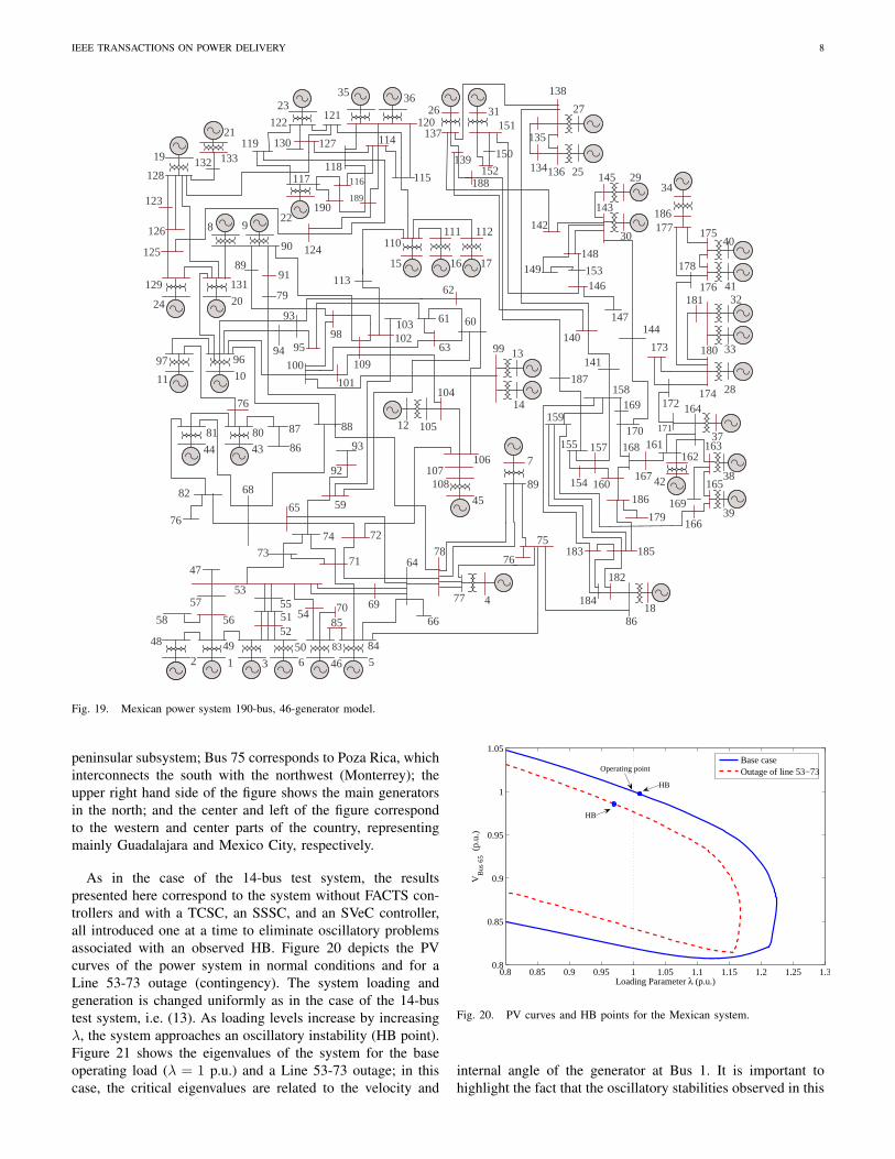
The studies presented here are based on a reduced modelrepresenting the northern, northeastern, western, central andsoutheastern areas of the system. This equivalent systemconsists of 190 buses, 265 400/230/138/115 kV transmissionlines, 46 generators, and 90 loads modeled as constant powerloads to simulate maximum system stress; in this model,no interconnections with the northwest are considered. Asingle-line diagram of the reduced model is shown in Fig.19.Buses 1-6 and 46 represent hydro generators in the southern
IEEE TRANSACTIONS ON POWER DELIVERY 8
2
48 491
506
5657
58525155
53
4683
584
3
8554 70
7374
71
72
6865
64
6966
78
77 4
76
75
7
8945
108107
106
59
92
934481
4380
82
87
86
76
88 12 105
10476
1197
1096 100
94
93
95
101109
98 102103
14
1399
62
6061
63
24
12920131
8 9
90
79
9189
125
126
123
19
21
128133132
11315 16 17
110111 112
2335
122 120121
119
124
189
117
22
116 115
36
127130
118
114
190
41
40175
176
178
30
29145
143
34
186177
148
33
32
180
181
28174
173
172
42
162
37
164
171
153146
147
149
142
161
38
163
1886
182
184
185183
39
165
169
167
168170
160
166
169
186179
157
154
158
159
141
140144
25
27138
136
26 31151
137
155
139
188
135
134150
152
187
47
Fig. 19. Mexican power system 190-bus, 46-generator model.
peninsular subsystem; Bus 75 corresponds to Poza Rica, whichinterconnects the south with the northwest (Monterrey); theupper right hand side of the figure shows the main generatorsin the north; and the center and left of the figure correspondto the western and center parts of the country, representingmainly Guadalajara and Mexico City, respectively.
As in the case of the 14-bus test system, the resultspresented here correspond to the system without FACTS con-trollers and with a TCSC, an SSSC, and an SVeC controller,all introduced one at a time to eliminate oscillatory problemsassociated with an observed HB. Figure 20 depicts the PVcurves of the power system in normal conditions and for aLine 53-73 outage (contingency). The system loading andgeneration is changed uniformly as in the case of the 14-bustest system, i.e. (13). As loading levels increase by increasingλ, the system approaches an oscillatory instability (HB point).Figure 21 shows the eigenvalues of the system for the baseoperating load (λ = 1 p.u.) and a Line 53-73 outage; in thiscase, the critical eigenvalues are related to the velocity and
0.8 0.85 0.9 0.95 1 1.05 1.1 1.15 1.2 1.25 1.30.8
0.85
0.9
0.95
1
1.05
Loading Parameter λ (p.u.)
VB
us 6
5 (p.
u.)
Base caseOutage of line 53−73Operating point
HB
HB
Fig. 20. PV curves and HB points for the Mexican system.
internal angle of the generator at Bus 1. It is important tohighlight the fact that the oscillatory stabilities observed in this

IEEE TRANSACTIONS ON POWER DELIVERY 9
−2 −1.5 −1 −0.5 0−15
−10
−5
0
5
10
15
Real
Imag
Critical Eigenvalues
Fig. 21. Eigenvalues of the Mexican system at λ = 1 p.u. with an outageof Line 53-73.
TABLE ICRITICAL DAMPING RATIOS AND FREQUENCIES WITH FACTS
CONTROLLERS AT DIFFERENT LOCATIONS FOR THE MEXICAN SYSTEM
SVeC TCSC SSSC
Line f Hz ζ % f Hz ζ % f Hz ζ %
54-53 0.5936 0.8079 0.5936 0.8077 0.5932 0.7731
57-53 0.5759 3.2292 0.4766 1.5338 0.5854 2.7987
73-71 0.5741 0.6783 0.5861 0.6871 0.5872 0.7622
74-59 0.6113 0.8518 0.6193 0.3664 0.6018 0.8548
71-72 0.5914 0.7887 0.5915 0.7817 0.5901 0.8211
64-65 0.5916 0.7890 0.5922 0.7534 0.5883 0.8911
case are due to the constant power load model used, whichstresses the system more than other load models such as aconstant impedance ones; no oscillatory problems are observedwith a constant impedance model.
To find the best suitable location of the FACTS controllersunder study for the removal of the oscillatory instabilityobserved when the Line 53-73 is tripped, small-perturbation(eigenvalue) analyses were performed for the system with theline removed. In these studies, a 0.48 Hz unstable oscillatorymode with a damping ratio ζ = −1.4% was observed atλ = 1p.u., due to the speed and angle of the generator atBus 1; this mode corresponds to an interaction between thesouth system against machines in the center, southeastern andpeninsular systems. Table I shows the critical damping andfrequency values obtained for several of the transmission linesconsidered as possible candidates for placement of an SVeC,TCSC or SSSC when the Line 53-73 is tripped. Observe thatthe best candidate location to prevent the HB problem is Line57-53 (highlighted); this is confirmed through time-domainsimulations. In this particular case, the SVeC shows a similarperformance as the SSSC and better performance than theTCSC.
Figure 22 depicts the PV curves for the system with eachof the FACTS controllers under study connected in series withLine 57-53 with a compensation level of 50%; in this case,the active power flowing through the line is increased andcontrolled from 815.27 MW to 924.13 MW. The controllerswere tuned through an eigenvalue analysis at base loading
0.8 0.85 0.9 0.95 1 1.05 1.1 1.15 1.2 1.25 1.30.8
0.85
0.9
0.95
1
1.05
Loading Parameter λ (p.u.)
VB
us 6
5 (p.
u.)
Base caseOutage of line 53−73Operating point
HB:SSSC,TCSC&SMC
HB: SSSC,TCSC&SMC
Fig. 22. PV curves for the Mexican system.
05
1015
2025
30
0
10
20
30
40
0.995
1
1.005
1.01
Time (s)Generator Number
Spe
ed d
esvi
atio
n (p
.u)
Fig. 23. Generators speed oscillation due to an outage of Line 53-73 atλ = 1 p.u.
conditions with Line 53-73 removed and a target dampingof 3%; however, only the SVeC could be tuned to thesespecifications, with the other two controllers only providingthe maximum damping shown in Table I, i.e. about 1.5%for the TCSC and 2.8% for the SSSC. (Note that it shouldpossible to improve the damping ratios of the TSCS andSSSC controllers through the utilization of more sophisticatedcontrollers as discussed for example in [15] for the TCSC.)
05
1015
2025
30
0
10
20
30
40
0.998
0.9985
0.999
0.9995
1
1.0005
1.001
1.0015
1.002
Time (s)Generator Number
Spe
ed D
esvi
atio
n (p
.u.)
Fig. 24. Generators speed oscillation due to outage of Line 53-73 at λ = 1p.u. with SVeC.

IEEE TRANSACTIONS ON POWER DELIVERY 10
05
1015
2025
30
0
10
20
30
40
0.997
0.998
0.999
1
1.001
1.002
Time (s)Generator Number
Spe
ed D
esvi
atio
n (p
.u.)
Fig. 25. Generators speed oscillation due to outage of Line 53-73 at λ = 1p.u. with TCSC.
05
1015
2025
30
0
10
20
30
40
0.998
0.9985
0.999
0.9995
1
1.0005
1.001
1.0015
1.002
Time (s)Generator Number
Spe
ed D
esvi
atio
n (p
.u.)
Fig. 26. Generators speed oscillation due to outage of Line 53-73 at λ = 1p.u. with SSSC.
Observe that the controllers do not significantly affect the HBobserved for the system without contingencies (base case),whereas the appearance of the oscillatory problem for thesystem without Line 53-73 conditions is moved to a higherloading condition (from λ = 0.97p.u. to 1.02p.u.); this is tobe expected given that the latter are the system conditions usedto place and tune the controllers. This is confirmed throughthe time-domain simulation results depicted in Figs. 23-26,where it can be observed that the SVeC and SSSC providebetter damping for a Line 53-73 trip than the TCSC.
VI. CONCLUSIONS
A simple stability model and controls based on the ap-propriate modulation of an equivalent series reactance of anSVeC were proposed and discussed in this paper. Full stabilitystudies, i.e. voltage, small-perturbation and transient stabilityanalyses were used to verify the impact of the SVeC in amultimachine power system. The performance of the SVeCwith respect to similar series-connected FACTS controllers,namely TCSC and SSSC, were also presented. The resultsobtained for a couple of realistic test systems demonstrate theapplicability of the controller and its ability to eliminate poweroscillations triggered by system disturbances.
The results obtained demonstrate that the SVeC performsvery similarly if not better than the TCSC and SSSC. Hence,
it may be concluded that the SVeC is certainly a competitive,and in some cases better, option compared to current series-connected FACTS controllers, considering that the direct ac/acpower conversion principle of the SVeC leads to an overallmore compact, simpler and durable controller, with no largedc-link energy storage components and a simpler PWM con-troller.
REFERENCES
[1] “Final Report on the August 14, 2003 blackout in the United States andCanada: Causes and recommendations,” U. S. - Canada Power SystemOutage Task Force, April 2004.
[2] C. W. Taylor and D. C. Erickson “Recording and analyzing the July 2cascading outage,” IEEE Computer Applications in Power, vol. 10, Jan.1997, pp. 26-30.
[3] N. G. Hingorani and L. Gyugyi, Understanding FACTS: Concepts andTechnology of Flexible AC Transmission Systems, Piscataway, NJ: IEEEPress, 2000.
[4] L. Gyugyi, “Dynamic compensation of AC transmission lines by solid-state synchronous voltage sources,” IEEE Trans. Power Del., vol. 9, no.2, pp. 904-911, Apr. 1994.
[5] L. Gyugyi, C. D. Schauder, S. L. Williams, T. R. Rietman, D. R.Torgerson, and A. Edris, “The unified power flow controller: A newapproach to power transmission control,” IEEE Trans. Power Del., vol.10, no. 2, pp. 1085-1097, Apr. 1995.
[6] L. Gyugyi, C. Schauder, and K. K. Sen, “Static synchronous seriescompensator: A solid-state approach to the series compensation of trans-mission lines,” IEEE Trans. Power Del., vol. 12, no. 1, pp. 406-417, Jan.1997.
[7] K. K. Sen, “Static synchronous series compensator: Theory, modeling,and application,” IEEE Trans. Power Del., vol. 13, no. 1, pp. 241-246,Jan. 1998.
[8] C. D. Savelli, C. P. Pellanda, N. Martins, J. P. N. Macedo, A. A. Barbosa,and S. G. Luz, “Robust Signals for the TCSC Oscillation DampingControllers of the Brazilian North-South Interconnection ConsideringMultiple Power Flow Scenarios and External Disturbances”, Proc. PowerEngineering Society General Meeting, Tampa, FL, June 2007.
[9] L. A. C. Lopes and G. Joos, “Pulse width modulated capacitor for seriescompensation,” IEEE Trans. Power Electron., vol. 16, no. 2, pp. 167-174,Mar. 2001.
[10] G. Venkataramanan and B. K. Johnson, “Pulse width modulated seriescompensator,” IEE Proc. Gen., Trans. and Dist., vol. 149, no. 1, pp. 71-75, Jan. 2002.
[11] G. Venkataramanan, “Three-phase vector switching converters for powerflow control,” IEE Proc. Elect. Power Appl., vol. 151, no. 3, pp. 321-333,May 2004.
[12] F. Mancilla-David and G. Venkataramanan, “A pulse width modulatedAC link unified power flow controller,” in Proc. IEEE Power EngineeringSociety General Meeting, San Francisco, CA, vol. 2, pp. 1314-1321, July2005.
[13] F. Z. Peng, L. Chen, and F. Zhang, “Simple topologies of PWM ac-acconverters,” IEEE Power Electron. Letters, vol. 1, no. 1, pp. 10-13, March2003.
[14] F. Mancilla-David, S. Bhattacharya, G. Venkataramanan, “A Compara-tive Evaluation of Series Power-Flow Controllers Using DC- and AC-LinkConverters,” IEEE Trans. Power Del., vol. 23, no. 2, pp. 985-996, April2008.
[15] V. Venkatasubramanian and C. W. Taylor, “Improving Pacific Intertiestability using Slatt thyristor controlled series compensation,” in Proc.PES Winter Meeting, pp. 1468-1470, Jan. 2000.
[16] O. Simon, J. Mahlein, M. N. Muenzer, and M. Bruckmann, “Modernsolutions for industrial matrix-converter applications,” IEEE Trans. In-dustrial Electronics, vol. 49, no. 2, pp. 401-406, April 2002
[17] P. Wheeler, J. Clare, L. Empringham, M. Apap, and M. Bland, “Matrixconverters,” Power Engineering Journal, vol. 16, no. 6, pp. 273-282, Dec.2002.
[18] J. M. Ramirez, J. M. Gonzalez, and M. L. Crow, “Steady state formu-lation of FACTS devices based on ac/ac converters,” IEE Proc. ElectricPower Appl., vol. 1, no. 4, pp. 619-631, July 2007
[19] J. M.Gonzalez and J. M. Ramirez, “AC/AC series converter in transientstability,” in Proc. NAPS, pp. 205-211, Las Cruces, New Mexico, Sept.2007.
IEEE TRANSACTIONS ON POWER DELIVERY 11
[20] J. M. Ramirez and J. M. Gonzalez, “Steady-state and transient stabilitystudies with an ac-ac PWM series compensator,” IEEE-PES SummerMeeting, Tampa, Florida, 2007.
[21] R. Seydel, Practical Bifurcation and Stability Analysis: From Equilib-rium to Chaos, Second Edition, Springer-Verlag, New York, 1994.
[22] P. Kundur, Power System Stability and Control. McGraw Hill, New York,1994.
[23] C. A. Canizares, editor, “Voltage stability assessment: Concepts, prac-tices and tools,” IEEE/PES Power System Stability Subcommittee, Tech.Rep. SP101PSS, August 2002.
[24] D. J. Hill and I. M. Y. Mareels, “Stability theory for differential algebraicsystems with application to power systems,” IEEE Trans. Circuits andSystems, vol. 37, no. 11, pp. 1416-1423, Nov. 1990.
[25] N. Mithulananthan, “Hopf Bifurcation Control and Indices for PowerSystem with Interacting Generator and FACTS Controllers,” PhD thesis,University of Waterloo, Waterloo, ON, Canada, 2002. [Online]. Available:http://thunderbox.uwaterloo.ca/ claudio/thesis/mithulan
[26] C. A. Canizares, F. L. Alvarado, C. L. DeMarco, I. Dobson, and W. F.Long, “Point of Collapse Methods Applied to AC/DC Power Systems,”IEEE Trans. Power Systems, vol. 7, no. 2, May 1992, pp. 673-683.
[27] V. Ajjarapu and B. Lee, “Bifurcation theory and its application tononlinear dynamical phenomena in power systems,” IEEE Trans. PowerSystems, vol. 7, no. 2, pp. 424-431, Feb. 1992.
[28] C. A. Canizares and S. Hranilovic, “Transcritical and Hopf bifurcationsin ac/dc systems,” in Proc. Bulk Power System Voltage Phenomena III-Voltage Stability and Security, Davos, Switzerland, pp. 105-114, Aug.1994.
[29] E. H. Abed and P.P. Varaiya, “Nonlinear oscillation in power systems,”Int. J. Electric Power and Energy Systems, vol. 6, pp. 37-43, 1984.
[30] R. Mihalic and U. Gabrijel, “A structure-preserving energy function fora static series synchronous compensator,” IEEE Transactions on PowerSystems, vol. 19, no. 3, pp. 1501–1507, 2004.
[31] F. Milano, “Power System Analysis Toolbox: Documentation for PSATversion 2.0.0 β,” March 2007.
Juan Miguel Gonzalez obtained his BS in Electrical Engineering fromUniversidad de Colima, Mexico in 2004, and MSc in Electrical Engineeringfrom CINVESTAV, where he is pursuing a PhD degree. His primary area ofinterest is the modeling, simulation, analysis and control of FACTS devices.
Claudio A. Canizares (S’85, M’91, SM’00, F’07) received in April 1984the Electrical Engineer Diploma from the Escuela Politecnica Nacional,Quito-Ecuador, where he held different teaching and administrative positionsfrom 1983 to 1993. His MS (1988) and PhD (1991) degrees in ElectricalEngineering are from the University of Wisconsin-Madison. He has been at theUniversity of Waterloo since 1993, where he is currently a Full Professor. Hisresearch activities concentrate on the study of modeling, simulation, control,stability, computational and dispatch issues in power systems in the contextof competitive electricity markets.
Juan M. Ramırez obtained his BS in Electrical Engineering from Universidadde Guanajuato, Mexico in 1984; MSc in Electrical Engineering from UNAMin 1987; and PhD in Electrical Engineering from UANL in 1992. He joinedthe department of Electrical Engineering of CINVESTAV in 1999, where heis currently a Full-time Professor. His areas of interest are in FACTS devicesand control of electrical power systems.