ijet journal of engineering and technology...
TRANSCRIPT

International Journal of Engineering and Technology Volume 5 No. 9, September, 2015
ISSN: 2049-3444 © 2015 – IJET Publications UK. All rights reserved. 504
Experimental Determination of Starting Capacitor Capacitance for a
Refurbished Single-Phase Induction Motor
Peter M. Enyong Department of Electrical/Electronic Engineering
Technology; Auchi Polytechnic, Auchi, Nigeria
ABSTRACT
The refurbishment of a burnt laboratory 1.5kW single-phase induction motor was undertaken, with a view to demonstrating standard
practice in the interest of both students and the rewinding workshop personnel. In this paper, a brief review of the capacitor induction
motor is given. The necessary physical quantities from measurement/inspection of the motor useful in its design are detailed and the
significant rewinding parameters are computed and duly specified. The laboratory test results and the concomitant calculations
leading to the choice of capacitor are equally provided. The rewinding parameters realized included: the main concentric winding
turns as 29, 25 and 19 of standard wire gauge (SWG) 20 (holding 3 wires in hand); auxiliary concentric winding turns as 62 and 54
of SWG 22 (holding 1 wire in hand); 4No. pole-belts for each operational winding; and 180o spreading of pole-belts. The selected
capacitor was the electrolytic type whose capacitance was experimentally determined as 140uF. Observations from the workshop
tests showed the motor as being capable of starting and running currents of 22A and 3.6A, respectively; and a no-load rotor speed of
approximately 1500rpm.
Keywords: Single-Phase Motor, Design, Refurbishment, Capacitor Selection.
1. INTRODUCTION
An Overview
The induction motor is an a.c. motor in which the current in
the stator winding produces a rotating flux, Φrot, which
induces a current in the rotor winding, Irw, thus producing the
necessary torque, from the interaction of the two, Φrot and Irw
[Jackson (1973)]. It is that machine which requires slip to
maintain rotation, and by virtue of this rotation of its non-
static aspect, electrical energy is converted into mechanical
energy [Ostavic (1994); Bousbaine (1993)]. It is the most
widely used asynchronous machine in industries for various
duties [Shera et al (2012); Mehta & Mehta (2009)].
A single-phase induction motor, as the name implies, is an
induction motor that operates with a single-phase power
supply. For not being self-starting it usually requires two
windings (main and auxiliary windings) with a phase-splitting
angle between them to be able to produce torque and start
from rest. The phase-splitting angle is realized either by the
connection of a resistor or a capacitor in series with the
auxiliary (otherwise known as starting) winding [Parekh
(2003)]. They find application chiefly in homes and offices to
drive various electrical appliances such as ceiling fans,
blowers, blenders, water-pumps, washing machines, air-
conditioners, fridges, extractor fans and so on [Theraja
(2002); Bhattachary (1998)].
The Capacitor Motor
This is the type that has an external capacitor, C, in series
with the auxiliary winding so as to develop sufficient starting
torque while decreasing starting current. The main and
auxiliary windings are often connected in parallel and
arranged in space quadrature as in Fig.1. The capacitor
provides the required phase displacement making the current
in the auxiliary winding to lead that of the main winding, thus
providing the necessary condition for a travelling wave
production (though somewhat crude) in the motor; a
phenomenon which is also called phase splitting or phase
shifting [Jackson (1973); Engineering Student (2011)].
The capacitor may be used during the starting period only as
in a capacitor-start, induction-run motor requiring a
centrifugal switch, S, to disengage it after starting. This is,
however, applicable to the motor under consideration.
Otherwise, it can be permanently connected as in a
permanent-split capacitor motor which will require no
switch. In another version, the motor starts with one value of
capacitor and runs with another usually smaller value as in
capacitor-start, capacitor-run motor where the capacitors are
connected in parallel and the switch in series with the starting
capacitor. In both cases where a capacitor remains or is
placed in circuit during the running of the motor, the
operational power factor, p.f., of the motor is usually
improved.
Reason for this Work
Like any other machine a single-phase motor breaks down
under operation and becomes defective for various reasons
including fire incidents, supply voltage variation, short-
circuits, vibration, mal-operation or misapplication, extreme
overloading situations and starting duty under extreme low-
voltage conditions [Thornton & Armintor (2003); Mehala
(2010)]. The motor considered here was a laboratory
apparatus burnt mistakenly by application of very high
voltage to it. Proper refurbishment had to be carried out
which included the selection of appropriate starting capacitor
International Journal of Engineering and Technology (IJET) – Volume 5 No. 9, September, 2015
ISSN: 2049-3444 © 2015 – IJET Publications UK. All rights reserved. 505
by experimental method for the education of students and
rewinding workshop personnel alike.
Paper Organization
This 1st section serves, of course, as the introduction. Section
2 shall feature single-phase design computations. In Section 3
we shall deal with rewinding, initial tests and maintenance.
This shall be followed by the section on determination of the
starting capacitor capacitance. Next, in Section 5, is the
presentation of the results of the work-shop test-running of
the motor; whilst the 6th and the last section shall take care of
discussion, conclusion and recommendations.
2. SINGLE-PHASE MOTOR DESIGN
COMPUTATIONS
2.1. Motor Particulars & Design Parameters:
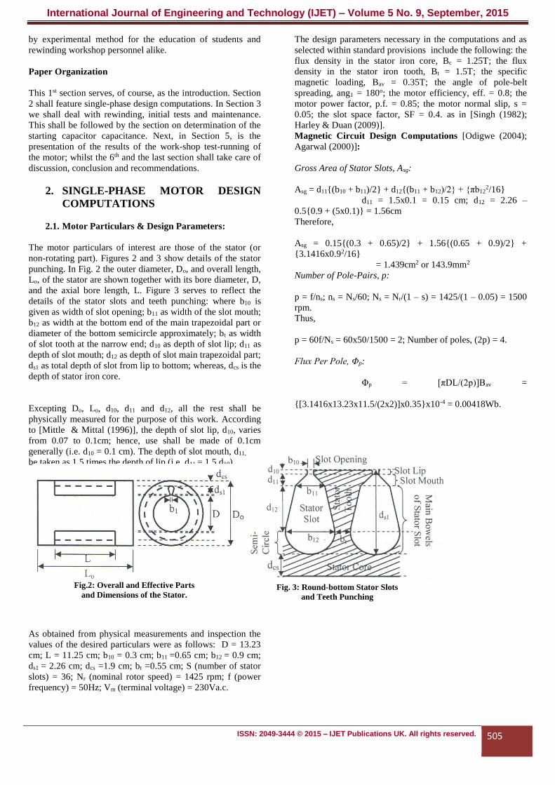
The motor particulars of interest are those of the stator (or
non-rotating part). Figures 2 and 3 show details of the stator
punching. In Fig. 2 the outer diameter, Do, and overall length,
Lo, of the stator are shown together with its bore diameter, D,
and the axial bore length, L. Figure 3 serves to reflect the
details of the stator slots and teeth punching: where b10 is
given as width of slot opening; b11 as width of the slot mouth;
b12 as width at the bottom end of the main trapezoidal part or
diameter of the bottom semicircle approximately; bt as width
of slot tooth at the narrow end; d10 as depth of slot lip; d11 as
depth of slot mouth; d12 as depth of slot main trapezoidal part;
ds1 as total depth of slot from lip to bottom; whereas, dcs is the
depth of stator iron core.
Excepting Do, Lo, d10, d11 and d12, all the rest shall be
physically measured for the purpose of this work. According
to [Mittle & Mittal (1996)], the depth of slot lip, d10, varies
from 0.07 to 0.1cm; hence, use shall be made of 0.1cm
generally (i.e. d10 = 0.1 cm). The depth of slot mouth, d11, can
be taken as 1.5 times the depth of lip (i.e. d11 = 1.5 d10).
As obtained from physical measurements and inspection the
values of the desired particulars were as follows: D = 13.23
cm; L = 11.25 cm; b10 = 0.3 cm; b11 =0.65 cm; b12 = 0.9 cm;
ds1 = 2.26 cm; dcs =1.9 cm; bt =0.55 cm; S (number of stator
slots) = 36; Nr (nominal rotor speed) = 1425 rpm; f (power
frequency) = 50Hz; Vm (terminal voltage) = 230Va.c.
The design parameters necessary in the computations and as
selected within standard provisions include the following: the
flux density in the stator iron core, Bc = 1.25T; the flux
density in the stator iron tooth, Bt = 1.5T; the specific
magnetic loading, Bav = 0.35T; the angle of pole-belt
spreading, ang1 = 180o; the motor efficiency, eff. = 0.8; the
motor power factor, p.f. = 0.85; the motor normal slip, s =
0.05; the slot space factor, SF = 0.4. as in [Singh (1982);
Harley & Duan (2009)].
Magnetic Circuit Design Computations [Odigwe (2004);
Agarwal (2000)]:
Gross Area of Stator Slots, Asg:
Asg = d11(b10 + b11)/2 + d12(b11 + b12)/2 + πb122/16
d11 = 1.5x0.1 = 0.15 cm; d12 = 2.26 –
0.50.9 + (5x0.1) = 1.56cm
Therefore,
Asg = 0.15(0.3 + 0.65)/2 + 1.56(0.65 + 0.9)/2 +
3.1416x0.92/16
= 1.439cm2 or 143.9mm2
Number of Pole-Pairs, p:
p = f/ns; ns = Ns/60; Ns = Nr/(1 – s) = 1425/(1 – 0.05) = 1500
rpm.
Thus,
p = 60f/Ns = 60x50/1500 = 2; Number of poles, (2p) = 4.
Flux Per Pole, Φp:
Φp = [πDL/(2p)]Bav =
[3.1416x13.23x11.5/(2x2)]x0.35x10-4 = 0.00418Wb.
Fig.2: Overall and Effective Parts
and Dimensions of the Stator. Fig. 3: Round-bottom Stator Slots
and Teeth Punching

International Journal of Engineering and Technology (IJET) – Volume 5 No. 9, September, 2015
ISSN: 2049-3444 © 2015 – IJET Publications UK. All rights reserved. 506
Electric Circuit Design Computations [Enyong (2008);
Mittle & Mittal (1996); Daniels (1976)]
Number of Phase-Belts (Pb):
𝑃𝑏 =360𝑜𝑝
𝑎𝑛𝑔1=
360𝑜𝑥2
180=
4 (𝑖. 𝑒. 4 𝑜𝑛 𝑡ℎ𝑒 𝑀𝑎𝑖𝑛 𝑎𝑛𝑑 4 𝑜𝑛 𝑡ℎ𝑒 𝐴𝑢𝑥𝑖𝑙𝑖𝑎𝑟𝑦) Number of
Slots per Phase-Belt of 1-Phase Motors (Q1):
𝑄1 =𝑆
𝑃𝑏=
36
4= 9
Slot Pitch Angle (a):
𝑎 =360𝑜𝑝
𝑆=
360𝑜
(36 2⁄ )= 20𝑜
The Longest Coil Span in Terms of Slot Pitches (g):
𝑔 = [(180 − 𝑎) 𝑎⁄ ] = (180
20) − 1 = 8
Individual Coil Spans of Main Winding in Slot-Pitches (ymk):
𝑦𝑚𝑘 = 𝑔 − 𝑢; 𝑦𝑚(𝑙𝑎𝑠𝑡) = 3; 𝑘 =
1,2,3, … ; 𝑢 = 0,2,4, … ;
𝑖. 𝑒. 𝑦𝑚1 = 8; 𝑦𝑚2 = 6, 𝑦𝑚3 = 4
Number of Coils per Phase-Belt of Main Winding, (Ncm):
𝑛𝑐𝑚 = 𝑟𝑜𝑢𝑛𝑑[(𝑄1 − 3)/
2] 𝑓𝑜𝑟 𝑚𝑎𝑖𝑛 𝑤𝑖𝑛𝑑𝑖𝑛𝑔 = 3
𝑛𝑐𝑎 = 𝑛𝑐𝑚 − 1 𝑓𝑜𝑟 𝑎𝑢𝑥 𝑤𝑖𝑛𝑑𝑖𝑛𝑔 = 2
Winding Factors (Kωm1) & (Kωa1):
𝐾𝑤𝑚1 =𝑠𝑖𝑛2(
8
2𝑥20)+𝑠𝑖𝑛2(
6
2𝑥20)+𝑠𝑖𝑛2(
4
2𝑥20)
𝑠𝑖𝑛(8
2𝑥20)+𝑠𝑖𝑛(
6
2𝑥20)+𝑠𝑖𝑛(
4
2𝑥20)
=
𝑠𝑖𝑛280+𝑠𝑖𝑛260+𝑠𝑖𝑛240
𝑠𝑖𝑛80+𝑠𝑖𝑛60+𝑠𝑖𝑛40=
2.133
2.4936= 0.8554
𝐾𝑤𝑎1 = 0.8
Number Of Turns Per Phase (Nm, Na) & Per Pole (N′m, N′a):
𝑁𝑚 =𝑉𝑚
4.44𝑓𝜙𝑝𝐾𝑤𝑚1=
230
4.44𝑥50𝑥0.00418𝑥0.8554= 290; 𝑁′𝑚 =
290
2𝑥2= 73
𝑁𝑎 = 2.5𝑁𝑚𝐾𝑤𝑚1 = 2.5𝑥290𝑥0.8554 =
620; 𝑁′𝑎 =620
2𝑥2= 155
Number of Turns of Individual Coils (Nmk & Nak):
For the main winding,
𝑁𝑚1 = 𝑠𝑖𝑛80
𝑠𝑖𝑛80+𝑠𝑖𝑛60+𝑠𝑖𝑛40 𝑥73 =
0.9848
2.4936𝑥73 =29
𝑁𝑚2 = 𝑠𝑖𝑛60
𝑠𝑖𝑛80+𝑠𝑖𝑛60+𝑠𝑖𝑛40 𝑥73 =
0.866
2.4936𝑥73 = 25
𝑁𝑚3 = 𝑠𝑖𝑛40
𝑠𝑖𝑛80+𝑠𝑖𝑛60+𝑠𝑖𝑛40 𝑥73 =
0.6428
2.4936𝑥73 =19
For the auxiliary winding,
𝑁𝑎1 = 𝑠𝑖𝑛80
𝑠𝑖𝑛80+𝑠𝑖𝑛60+𝑠𝑖𝑛40 𝑥155 =
0.9848
2.4936𝑥155 = 61
𝑁𝑎2 = 𝑠𝑖𝑛60
𝑠𝑖𝑛80+𝑠𝑖𝑛60+𝑠𝑖𝑛40 𝑥155 =
0.866
2.4936𝑥155 = 54
To avoid overstuffing the slots where both MW and AW
exist, Nm1 and Na1, in this case, it is usual practice to adopt (
Na1/2) = 31 (approximately), instead of 61 (a very practical
point to note).
Total Number of Conductors (Z):
For the main stator winding,
𝑍𝑚 = 2𝑚𝑁𝑚 ; 𝑚 − 𝑛𝑢𝑚𝑏𝑒𝑟 𝑜𝑓 𝑝ℎ𝑎𝑠𝑒𝑠 =
2𝑥1𝑥290 = 580
For the auxiliary stator winding,
𝑍𝑎 = 2𝑚𝑁𝑎 ; 𝑚 − 𝑛𝑢𝑚𝑏𝑒𝑟 𝑜𝑓 𝑝ℎ𝑎𝑠𝑒𝑠 =
2𝑥1𝑥620 = 1240

International Journal of Engineering and Technology (IJET) – Volume 5 No. 9, September, 2015
ISSN: 2049-3444 © 2015 – IJET Publications UK. All rights reserved. 507
Number of Conductors per Slot (Z′):
For the main stator winding,
𝑍′𝑚 =
𝑍𝑚
𝑆=
580
36= 16
For the auxiliary stator winding,
𝑍′𝑎 =
𝑍𝑎
𝑆=
1240
36= 34
Number of Conductors per Coil per Slot (Z′′):
It should be noted here that the main winding (or main wdg)
forms one layer whilst the auxiliary winding (or aux wdg)
forms another layer, both of which constitute the double-layer
formation of this machine. Thus,
𝑍′′𝑚 = 𝑍′𝑚 =
20 (𝑓𝑜𝑟 𝑚𝑎𝑖𝑛 𝑤𝑑𝑔) 𝑎𝑛𝑑 𝑍′′𝑎 = 𝑍′
𝑎 = 42 (𝑓𝑜𝑟 𝑎𝑢𝑥 𝑤𝑑𝑔)
Conductor Size or SWG (a′xm & a′xa):
Adopting space factor (SF) approach which often involves
insulated conductors, we compute wire cross-sectional areas,
a′xm and a′xa, for the main and auxiliary windings,
respectively, by means of which the necessary Standard Wire
Gauge (SWG) can be obtained from wire tables.
Thus, for the main winding,
𝑎𝑥𝑚′ = [
𝜋
4𝑑𝑥𝑚
′2 ] =(𝑆𝐹)𝐴𝑠𝑔
𝑍𝑚′ =
0.25𝑥143.9
16= 2.248𝑚𝑚2
And for the auxiliary winding (as already considered),
𝑎𝑥𝑎′ = 0.2𝑎𝑥𝑚..
′ = 0.2𝑥2.248 =
0.45𝑚𝑚2
The SWG selected for the main and auxiliary windings, from
Standard Wire Table (not given) are: SWG 20 (3 wires in
hand) and SWG 22 (1 wire in hand), respectively.
Motor Input Current, (Im):
𝐼𝑚 =
𝑘𝑊(103)
(𝑒𝑓𝑓)(𝑝𝑓)
𝑉𝑚=
[1.5𝑥103
0.8𝑥0.85]
230= 9.59𝐴
Checking Current Density (J) and Specific Electric Loading
(q) Values:
For Current Density (J) Check,
J = Im/axm = 9.59/2.248 = 4.27A/mm2 (OK, being within
range).
For Specific Electric Loading (q) Check,
qm = Imzm/(πD) = 9.59x620/3.1416x(13.23x10-2)
= 14,305A-C/m (OK, being within range).
3. REWINDING, INITIAL TESTS &
MAINTENANCE [Odigwe (2004); WEG
Group (2013)] Rewinding:
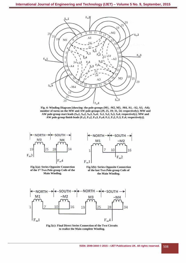
The motor was rewound as diagrammatically shown in Fig.
4, care being taken to have properly cleaned and insulated the
slots.
International Journal of Engineering and Technology (IJET) – Volume 5 No. 9, September, 2015
ISSN: 2049-3444 © 2015 – IJET Publications UK. All rights reserved. 508
Fig.5(c): Final Direct Series Connection of the Two Circuits
to realize the Main complete Winding.
Fig. 4: Winding Diagram [showing: the pole-groups (M1, -M2, M3, -M4, A1, -A2, A3, -A4);
number of turns on the MW and AW pole-groups (29, 25, 19; 31, 54; respectively); MW and
AW pole-group start leads (Sm1, Sm2, Sm3, Sm4; Sa1, Sa2, Sa3, Sa4; respectively); MW and
AW pole-group finish leads (Fm1, Fm2, Fm3, Fm4; Fa1, Fa2, Fa3, Fa4; respectively)].
Fig.5(b): Series-Opposite Connection
of the last Two Pole-group Coils of
the Main Winding.
Fig.5(a): Series-Opposite Connection
of the 1st Two Pole-group Coils of the
Main Winding.

International Journal of Engineering and Technology (IJET) – Volume 5 No. 9, September, 2015
ISSN: 2049-3444 © 2015 – IJET Publications UK. All rights reserved. 509
Initial Tests
Preliminary Workshop Tests:
These were carried out i) to check the line-to-neutral and line-
to-frame insulation resistance of the windings; and ii) to
ascertain the continuity of the coils and winding leads.
For the Insulation Resistance Test, use was made of a 500V
megohmmeter (battery-operated, digital display type – BM
221, AVO INT. LTD., England) and the following
readings were obtained:
Fm1 – Fa1 Insulation Resistance = 54 MΩ; Fm1 – Frame
Insulation Resistance = 87 MΩ
Fa1 – Frame Insulation Resistance = 90 MΩ.
The readings were obtained at 300C machine/ambient
temperature and after 1minute application of the test voltage
(d.c.).
For the Continuity Test, using the same instrument, the
readings were:
Fm1 – Fm4 Insulation Resistance = 0.00 MΩ; Fa1 – Fa4
Insulation Resistance = 0.00 MΩ.
Readings OK in both cases.
Machine Maintenance:
Among the aspects of the motor that needed maintenance
before reassembly included the cooling fan which had to be
replaced and the bearings that needed to be extracted, washed
with petrol and fresh grease applied.
4. DETERMINATION OF THE START
CAPACITOR CAPACITANCE (C) Results of the Laboratory Short-Circuit Tests:
These were as given in Table 1 that follows.
Table 1: Results of Short-circuit Tests for Capacitor Selection
S/No.
MACHINE
WINDING(S) IN
CIRCUIT
SHORT-
CIRCUIT
POWER
SHORT-
CIRCUIT
VOLTAGE
SHORT-
CIRCUIT
CURRENT
REMARKS
1 Main and Auxiliary
Windings in Parallel
Psc1 = 320W Vsc1= 52V Isc1 = 10A @ 35oC
2 Main Winding Only Psc2 = 480W Vsc1= 74V Isc2 = 10A @ 35oC
Capacitor Capacitance Computations: [Gopta (2005)]
Parameters of the Combined Main and Auxiliary Windings:
Impedance of the Main and Auxiliary Windings paralleled
|𝑍| =𝑉𝑠𝑐1
𝐼𝑠𝑐1=
52
10= 5.2ΩG
Power factor angle of machine with paralleled windings
∅ = 𝑐𝑜𝑠−1 𝑃𝑠𝑐1
𝑉𝑠𝑐1𝐼𝑠𝑐1=
𝑐𝑜𝑠−1 320
52𝑥10= 52𝑜
Resistance and Reactance of the paralleled windings (R & X)
𝑅 = |𝑍|𝑐𝑜𝑠∅ = 5.2𝑐𝑜𝑠52𝑜 = 3.2Ω; 𝑋 = |𝑍|𝑠𝑖𝑛∅
= 5.2𝑠𝑖𝑛52𝑜 = 4.1Ω
Parameters of the Main Winding only:
Impedance of the Main Windings separately
|𝑍𝑚| =𝑉𝑠𝑐2
𝐼𝑠𝑐2=
74
10= 7.4Ω
Power factor angle of machine with paralleled windings
∅𝑚 = 𝑐𝑜𝑠−1𝑃𝑠𝑐2
𝑉𝑠𝑐2𝐼𝑠𝑐2
= 𝑐𝑜𝑠−1480
74𝑥10= 49.56𝑜
Resistance and Reactance of the paralleled windings (R & X)
𝑅𝑚 = |𝑍𝑚|𝑐𝑜𝑠∅𝑚 = 7.4𝑐𝑜𝑠49.56𝑜 = 4.8Ω; 𝑋𝑚
= |𝑍|𝑠𝑖𝑛 = 7.4𝑠𝑖𝑛49.56𝑜
= 5.63Ω
Parameters of the Auxiliary Winding only:
Resistance of the Auxiliary Winding separately
𝑅𝑎 =𝑅𝑚𝑅
(𝑅𝑚−𝑅)=
4.8𝑥3.2
(4.8−3.2)= 9.6Ω
Resistance of the Auxiliary Winding separately
𝑋𝑎 =𝑋𝑚𝑋
(𝑋𝑚 − 𝑋)=
5.6𝑥4.1
(5.6 − 4.1)= 15.1Ω
Parameters of the Starting Circuit having Capacitor in Series
with the Auxiliary Winding:
Starting circuit composite reactance, Xst

International Journal of Engineering and Technology (IJET) – Volume 5 No. 9, September, 2015
ISSN: 2049-3444 © 2015 – IJET Publications UK. All rights reserved. 510
𝑋𝑠𝑡 = 𝑋𝑎 − 𝑋𝑐 = 15.1 − 𝑋𝑐; 𝑤ℎ𝑒𝑟𝑒 𝑋𝑐
= 𝐶𝑎𝑝𝑎𝑐𝑖𝑡𝑜𝑟 𝑅𝑒𝑎𝑐𝑡𝑎𝑛𝑐𝑒
Power factor angle of machine with starting circuit composite
reactance
∅𝑠𝑡 = (∅𝑚 − 90𝑜); 𝑠𝑖𝑛𝑐𝑒 |∅𝑠𝑡| + |∅𝑚| =
90𝑜𝑓𝑜𝑟 𝑠𝑡𝑎𝑟𝑡𝑖𝑛𝑔
𝑖. 𝑒. ∅𝑠𝑡 = 49.56 − 90 =
−40.44𝑜(𝑏𝑒𝑖𝑛𝑔 𝑎 𝑙𝑒𝑎𝑑𝑖𝑛𝑔 𝑎𝑛𝑔𝑙𝑒)
Now, 𝑡𝑎𝑛∅𝑠𝑡 =(𝑋𝑎−𝑋𝑐)
𝑅𝑎 𝑎𝑛𝑑 𝑋𝑐 = 𝑋𝑎 −
𝑅𝑎𝑡𝑎𝑛∅𝑠𝑡
𝑖. 𝑒. 𝑋𝑐 = 15.1 −
[9.6 tan(−40.44𝑜)] = 15.1 + 8.18 = 23.28Ω
Capacitance of the Starting Capacitor (C):
𝑪 = 12𝜋𝑓𝑋𝑐
⁄ =
1(2𝜋 ∗ 50 ∗ 23.28)⁄ = 136.7𝑢𝐹 𝑜𝑟 𝟏𝟒𝟎𝒖𝑭.
Electrolytic type of capacitor is usually applicable in 1-phase
motor starting duties.
5. RESULTS OF WORKSHOP TEST-
RUNNING OF THE MOTOR Table 2 that follows shows the results observed when test-
running the motor.
Table 2: Test-Running Check Results S/No. ACTION RESULTS OBSERVED REMARKS
1) 330V(a.c.)
applied
through an
ammeter to
machine
without load.
i) Starting Current:
22 Amps
Direct-on-Line Starting
Current.
ii) Running Current:
3.6 Amps
No-Load current
iii) Running Speed:
1500rpm
No-Load Asynchronous
Speed.
6. DISCUSSION, CONCLUSION AND
RECOMMENDATION
Discussion
The starting current being 22/3.6 = 6.11 x (the running
current) satisfies the standard of 5 to 7 x (the running current)
as in [Theraja (2002)]. The no-load rotor speed obtained as
1500rpm by means of a stroboscope is considered okay since
the machine is a 4-pole motor. According to [Pyrhonen et al
(2008)], at no-load the rotor rotates approximately at
synchronous speed. The obtainment of the exact value of
synchronous speed can be traced to the regulation of the
stroboscope which did not favour reading of the actual rotor
speed. The starting capacitor capacitance was considered
okay since that of 0.5kW, 50Hz single-phase motor is 100uF
[Veinott (1970)] and the capacitor for a 2.2kW, 50Hz single-
phase motor from field work was rated 200 to 250uF,
275Vrms, electrolytic.
Conclusion
The task of proper rewinding of a 1.5kW single-phase
capacitor motor and selection of capacitor by laboratory
short-circuit tests was accomplished. The results compare
favourably with those of global best practice.
Recommendations
This design and implementation approach is recommendable
to every motor rewinding workshop in the country, for the
improvement of the practice of induction motor
refurbishment. For easy, quick and accurate design processes
the use of a digital computer is hereby recommended;
MATLAB being the software to choose for the purpose, other
computer program languages notwithstanding.
REFERENCES
Agarwal R. K. (2000): Principles of Electrical Machine
Design, 4th Ed., Delhi, S. K. Kataria & Sons.
Bhattacharya S. K. (1998): Electrical Machines, 2nd Ed., New
Delhi, Tata
McGraw-Hill Publishing Company Limited.
Bousbaine A. (1993): An Investigation into the Thermal
Modeling of Induction Motors; Ph.DThesis,
Electrical/Electronic Engineering; University of Sheffield.
Daniels A. R. (1976): Introduction to Electrical Machines,
Maiden Ed., London,Macmillan Press Limited.
Engineering Student (2011): Single-phase Induction Motors;
estudent24h.blogspot.com/2011/06/single-phase-induction-
motor.html
Enyong P. M. (2008): Refurbishment and Steady-State
Performance Analysis of a 3-phase Induction Motor; M. Eng.
Thesis, Elect./Elect. Engng. Dept., University of Benin,
Benin-City, Nigeria.

International Journal of Engineering and Technology (IJET) – Volume 5 No. 9, September, 2015
ISSN: 2049-3444 © 2015 – IJET Publications UK. All rights reserved. 511
Gupta J. B. (2005): Theory & Performance of Electrical
Machines; 14th Ed.; Nai Sarak, Delhi; S. K. Kataria & Sons.
Harley R. G. & Duan Y. (2009): Traditional Design of Cage
Rotor Induction Motors; Lecture Series of Georgia Institute
of Technology.
Jackson K. G. (1973): Dictionary of Electrical Engineering;
London; Newnes-Butterworths.
Mehala N. (2010): Condition Monitoring & Fault Diagnosis
of Induction Motor Using Motor Current Signature
Analysis; PhD Thesis, Electrical Engineering Department;
National Institute of Technology, Kurukshetra, India.
Mehta V. K. and Mehta Rohit (2009): Principles of Electrical
Machines, 2nd Ed., New Delhi,S. Chand & Company Limited.
Mittle V. N. & Mittal A. (1996): Design of Electrical
Machines, 4th Ed., Nai Sarak, Delhi,Standard Publishers
Distributors.
Odigwe I. (2004): Performance Characteristics of a Rewound
Capacitor Start-and-Run Single-Phase Induction Motor; M.
Eng. Thesis,Dept. of Elect./Elect. Engng, University of
Benin, Benin-City. Nigeria.
Ostovic V. (1994): Computer-aided Analysis of Electric
Machines; London; Prentice Hall International (UK) Limited.
Parekh R. (2003): AC Induction Motor Fundamentals;
U.S.A.; Microchip Technology Inc. AN887; DS00887A.
Pyrhonen J. et al (2008): Design of Rotating Electrical
Machines; Chichester, West Sussex; John Wiley & Sons Ltd.
Shera S et al (2012): Performance Evaluation of Three-Phase
Induction Motor Based on No-Load & Blocked-Rotor Test
Using MATLAB, International Journal of Science,
Environment & Technology, Vol. 1, No 5, pp.541-547.
Singh B. (1982): Electrical Machine Design, New Delhi,
Vikas Publishing House PVT Limited.
Theraja B. L. (2002): Fundamentals of Electrical
Engineering and Electronics, New Delhi, S. Chand & Co.
Limited.
Thornton E. J. & Armintor J. R. (2008): The Fundamentals of
AC Electric Induction Motor Design Application;
Proceedings of the 20th International Pump Symposium.
Veinott C. G. (1970): Fractional & Subfractional Horse-
power Electric Motor; 3rd Edn., New York; McGraw-Hill
Book Co.WEG Group (2013): Low and High Voltage Three-
Phase Induction Motors – Installation, Operation and
Maintenance Manual; Doc. No. 1371757; Energy Business
Unit; Jaragua do Sul, Brazil.