ikelite product instruction manualdocs.ikelite.com/instructions/6146.07-instructions.pdf ·...
TRANSCRIPT

Digi ta l HousingI n s t r u c t i o n M a n u a l6146.07 Canon Powershot G7 X
Thank you for your purchase of Ikelite equipment. Please read thisinstruction manual completely before attempting to operate or divewith this product. Please refer to the back page of this manual toregister your Ikelite product.
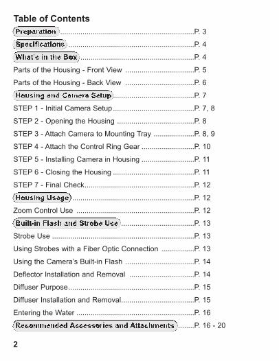
Table of ContentsPreparation ..................................................................P. 3
Specifications ..............................................................P. 4
What’s in the Box ........................................................P. 4
Parts of the Housing - Front View ..................................P. 5
Parts of the Housing - Back View ..................................P. 6
Housing and Camera Setup ........................................P. 7
STEP 1 - Initial Camera Setup ........................................P. 7, 8
STEP 2 - Opening the Housing ......................................P. 8
STEP 3 - Attach Camera to Mounting Tray ....................P. 8, 9
STEP 4 - Attach the Control Ring Gear ..........................P. 10
STEP 5 - Installing Camera in Housing ..........................P. 11
STEP 6 - Closing the Housing ........................................P. 11
STEP 7 - Final Check......................................................P. 12
Housing Usage ............................................................P. 12
Zoom Control Use ..........................................................P. 12
Built-in Flash and Strobe Use ....................................P. 13
Strobe Use ......................................................................P. 13
Using Strobes with a Fiber Optic Connection ................P. 13
Using the Camera’s Built-in Flash ..................................P. 14
Deflector Installation and Removal ................................P. 14
Diffuser Purpose..............................................................P. 15
Diffuser Installation and Removal....................................P. 15
Entering the Water ..........................................................P. 16
Recommended Accessories and Attachments ........P. 16 - 20
2
3
Table of Contents - continuedMaintenance ................................................................P. 21 - 25
Photo Tips ..................................................................P. 26
Troubleshooting ........................................................P. 27 - 29
Spare Parts ..................................................................P. 29
Customer Support ......................................................P. 30
Limited Warranty ........................................................P. 30
Returning Products for Service ................................P. 31
Product Registration ..................................................Back Page
This product has been water pressure tested at the factory and is depthrated to 200 ft (60m). Thoroughly inspect and immerse the emptyhousing completely in water before installing a camera. If any foggingoccurs or droplets of water enter the housing, do not install a camera.Clean the main housing o-ring and retest to make sure that it iswatertight. Refer to the Troubleshooting section, page 27.
Please read your camera manual thoroughly to have a fullunderstanding of each camera function.
If you are new to underwater photography, be sure to read the PhotoTips section, page 26.
Preparation
4
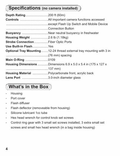
Depth Rating..........................200 ft (60m)Controls ................................All important camera functions accessed ................................................except Flash Up Switch and Mobile Device ................................................Connection ButtonBuoyancy ..............................Near neutral buoyancy in freshwaterHousing Weight ....................2.6 lb (1.18kg)Strobe Connection ................Fiber Optic PortsUse Built-in Flash..................YesOptional Tray Mounting ........12-24 thread external tray mounting with 3 in ................................................(76 mm) spacingMain O-Ring ..........................0109Housing Dimensions ............Dimensions 6.9 x 5.0 x 5.4 in (175 x 127 x ................................................137 mm) Housing Material ..................Polycarbonate front, acrylic backLens Port ..............................3.0-inch diameter glass
Specifications (no camera installed)
What’s in the Box- Housing- Port cover- Flash diffuser- Flash deflector (removeable from housing)- Silicone lubricant 1cc tube- Hex head wrench for control knob set screws- Control ring gear with 3 small set screws installed, 3 extra small set
screws and small hex head wrench (in a bag inside housing)
5
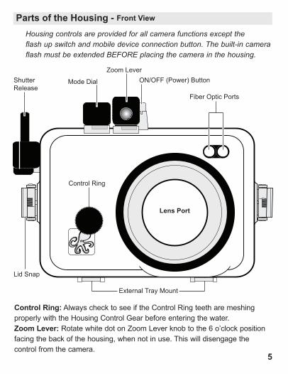
Parts of the Housing - Front View Housing controls are provided for all camera functions except theflash up switch and mobile device connection button. The built-in cameraflash must be extended BEFORE placing the camera in the housing.
Control Ring: Always check to see if the Control Ring teeth are meshingproperly with the Housing Control Gear before entering the water.Zoom Lever: Rotate white dot on Zoom Lever knob to the 6 o’clock positionfacing the back of the housing, when not in use. This will disengage thecontrol from the camera.
Mode DialShutterRelease
Zoom Lever
External Tray Mount
Control Ring
Lid Snap
Lens Port
ON/OFF (Power) Button
Fiber Optic Ports
6
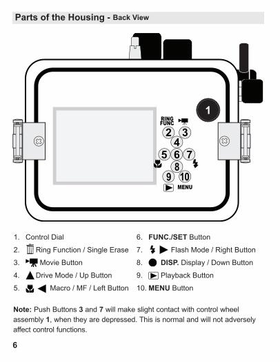
Parts of the Housing - Back View
54
2
768
9 10
3
MENU
FUNCRING
1
1. Control Dial
2. Ring Function / Single Erase
3. Movie Button
4. Drive Mode / Up Button
5. Macro / MF / Left Button
6. FUNC./SET Button 7. Flash Mode / Right Button
8. DISP. Display / Down Button9. Playback Button
10.MENU Button
Note: Push Buttons 3 and 7 will make slight contact with control wheelassembly 1, when they are depressed. This is normal and will not adverselyaffect control functions.
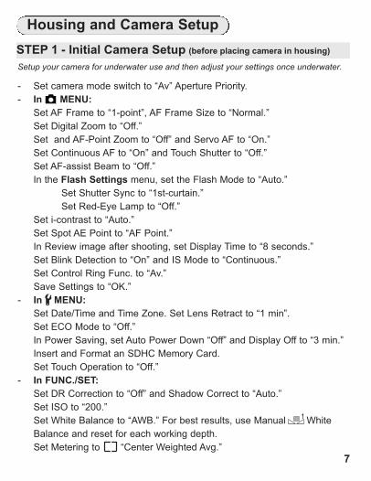
Housing and Camera SetupSTEP 1 - Initial Camera Setup (before placing camera in housing)
7
Setup your camera for underwater use and then adjust your settings once underwater.
- Set camera mode switch to “Av” Aperture Priority.- In MENU:
Set AF Frame to “1-point”, AF Frame Size to “Normal.”Set Digital Zoom to “Off.”Set and AF-Point Zoom to “Off” and Servo AF to “On.”Set Continuous AF to “On” and Touch Shutter to “Off.”Set AF-assist Beam to “Off.”In the Flash Settings menu, set the Flash Mode to “Auto.”
Set Shutter Sync to “1st-curtain.”Set Red-Eye Lamp to “Off.”
Set i-contrast to “Auto.”Set Spot AE Point to “AF Point.”In Review image after shooting, set Display Time to “8 seconds.”Set Blink Detection to “On” and IS Mode to “Continuous.”Set Control Ring Func. to “Av.”Save Settings to “OK.”
- In MENU:Set Date/Time and Time Zone. Set Lens Retract to “1 min”.Set ECO Mode to “Off.”In Power Saving, set Auto Power Down “Off” and Display Off to “3 min.”Insert and Format an SDHC Memory Card.Set Touch Operation to “Off.”
- In FUNC./SET:Set DR Correction to “Off” and Shadow Correct to “Auto.”Set ISO to “200.”Set White Balance to “AWB.” For best results, use Manual White Balance and reset for each working depth. Set Metering to “Center Weighted Avg.”
1
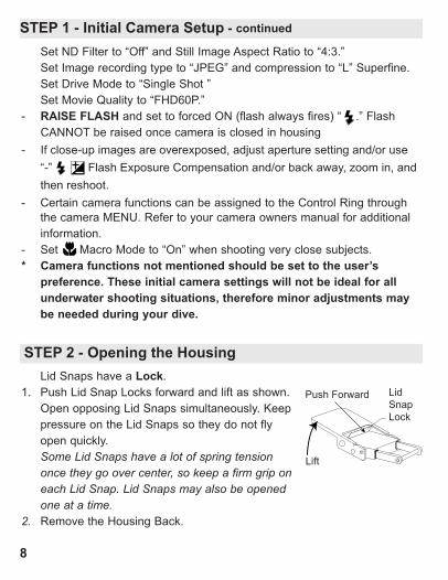
STEP 2 - Opening the Housing
8
Lid Snaps have a Lock.1. Push Lid Snap Locks forward and lift as shown.
Open opposing Lid Snaps simultaneously. Keeppressure on the Lid Snaps so they do not flyopen quickly. Some Lid Snaps have a lot of spring tensiononce they go over center, so keep a firm grip oneach Lid Snap. Lid Snaps may also be openedone at a time.
2. Remove the Housing Back.
Push Forward Lid Snap Lock
Lift
STEP 1 - Initial Camera Setup - continuedSet ND Filter to “Off” and Still Image Aspect Ratio to “4:3.”Set Image recording type to “JPEG” and compression to “L” Superfine.Set Drive Mode to “Single Shot ”Set Movie Quality to “FHD60P.”
- RAISE FLASH and set to forced ON (flash always fires) “ .” Flash CANNOT be raised once camera is closed in housing
- If close-up images are overexposed, adjust aperture setting and/or use“-” Flash Exposure Compensation and/or back away, zoom in, andthen reshoot.
- Certain camera functions can be assigned to the Control Ring throughthe camera MENU. Refer to your camera owners manual for additionalinformation.
- Set Macro Mode to “On” when shooting very close subjects.* Camera functions not mentioned should be set to the user’s
preference. These initial camera settings will not be ideal for allunderwater shooting situations, therefore minor adjustments maybe needed during your dive.
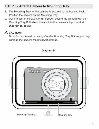
Diagram B
Canon
G7X
9
Mounting TrayMounting Tray Bolt
STEP 3 - Attach Camera to Mounting Tray
CAUTION:Do not cross thread or overtighten the Mounting Tray Bolt as you may damage the camera tripod socket threads.
1. The Mounting Tray for the camera is secured to the housing back. Position the camera on the Mounting Tray.
2. Using a coin or screwdriver (preferred), secure the camera with theMounting Tray Bolt which threads into the camera’s tripod socket,Diagram B, below.

Canon
G7X
Control Ring Gear(properly installed)
Set Screw Hex Head Wrench
STEP 4 - Attach the Control Ring GearThe supplied Control Ring Gear is attached to the camera control ring by3 small nylon hex head Set Screws. Place the Control Ring Gear overthe camera’s control ring before installing the camera in the housing.The Gear is a “press fit” over the lens. Gently tighten all three hex headscrews with the supplied Hex Head Wrench as show below. DO NOTovertighten or you may damage the gear, causing it to warp and bow outfrom the lens Control Ring. Make sure to test it’s function once installed.When installing the camera in the housing, make sure that the ControlRing Gear meshes properly with the smaller black housing gear.When removing the Gear, leave the Set Screws in the Gear. The SetScrews are very small and easy to lose. Extra Set Screws are includedwith your housing. We suggest that you leave the Gear installed as itmakes rotating the camera control ring easier when out of the housing.
10
Turn clockwise to tighten. DO NOT overtightenor you may warp or damage the gear.
11
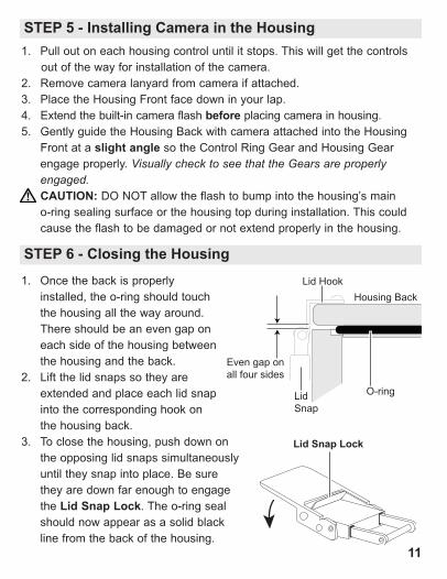
1. Pull out on each housing control until it stops. This will get the controls out of the way for installation of the camera.
2. Remove camera lanyard from camera if attached. 3. Place the Housing Front face down in your lap.4. Extend the built-in camera flash before placing camera in housing.5. Gently guide the Housing Back with camera attached into the Housing
Front at a slight angle so the Control Ring Gear and Housing Gearengage properly. Visually check to see that the Gears are properlyengaged.CAUTION: DO NOT allow the flash to bump into the housing’s maino-ring sealing surface or the housing top during installation. This couldcause the flash to be damaged or not extend properly in the housing.
STEP 5 - Installing Camera in the Housing
STEP 6 - Closing the Housing
1. Once the back is properlyinstalled, the o-ring should touchthe housing all the way around.There should be an even gap oneach side of the housing betweenthe housing and the back.
2. Lift the lid snaps so they areextended and place each lid snapinto the corresponding hook onthe housing back.
3. To close the housing, push down onthe opposing lid snaps simultaneouslyuntil they snap into place. Be surethey are down far enough to engagethe Lid Snap Lock. The o-ring sealshould now appear as a solid blackline from the back of the housing.
Housing Back
O-ring
Even gap onall four sides
Lid Hook
Lid Snap
Lid Snap Lock
STEP 7 - Final CheckThe clear housing permits instant visual inspection of the camera andsealing surfaces as well as complete monitoring of controls and cameraLCD screens. This housing has been factory water pressure tested to200 ft (60m).Once the housing is closed, recheck the o-ring seal. Double check thegap between the housing back and the housing. It should be even all theway around the housing.Look through the clear plastic back at the o-ring. You should see adarkened area or solid black line where the o-ring is compressed againstthe housing back. If you do not see an even black compression seal allthe way around the back, open the lid snaps, reseat the housing back andclose the lid snaps. Visually check the seal again.
12
UsageTurn the camera on and operate each of the housing controls to assureproper functioning. Take a few test shots on land. Make sure the FlashDiffuser is installed when using only the built-in camera flash, or installthe Flash Deflector when using external strobes, Page 15.
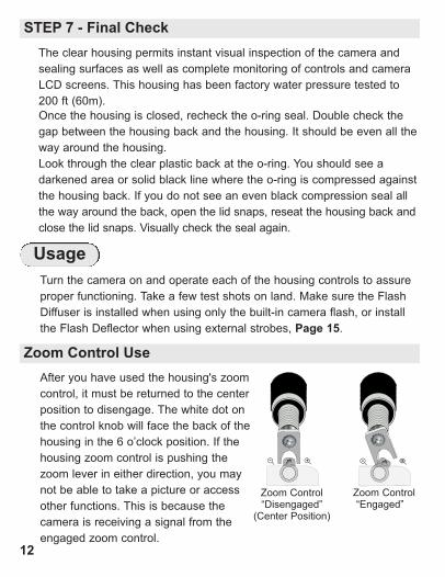
After you have used the housing's zoomcontrol, it must be returned to the centerposition to disengage. The white dot onthe control knob will face the back of thehousing in the 6 o’clock position. If thehousing zoom control is pushing thezoom lever in either direction, you maynot be able to take a picture or accessother functions. This is because thecamera is receiving a signal from theengaged zoom control.
+- +-
Zoom Control“Engaged”
Zoom Control “Disengaged”(Center Position)
Zoom Control Use
13
Using Strobes with a Fiber Optic Connection
Two ports on the front of the housing above the lens port are providedfor the connection of up to two Ikelite, SEA&SEA, or Olympus-type fiberoptic cords.
Always install the Flash Deflector when using external strobes, Page 14.
Built-in Flash and Strobe Use
The optional AF35 strobe triggers and provides automatic TTL exposureby watching the camera's built-in flash, without the need of fiber opticcords or sensors. Alternatively, two ports are provided on the front of thehousing for the connection of up to two Ikelite, SEA&SEA, or Olympustype fiber optic cords.
An included flash diffuser improves lighting quality when the camera'sbuilt-in flash is used. The built-in flash is effective between 1-3 feet(0.3-0.9m) from the subject in clear conditions. For best results, a colorcorrecting filter or external lighting is recommended. External lighting ismore powerful and can be placed in a position to virtually eliminate thebackscatter or "snow" from your underwater images.
Strobe Use
Always install the Flash Deflector when using external strobes, Page 14.
Always remove the Deflector and install the Flash Diffuser when usingonly the built-in flash, Page 14, 15.
If you are shooting with the camera’s built-in flash and the camera lensis set to the widest angle setting, you may need to zoom the lens slightlyor a dark area may appear in a lower corner of close-up photographs.The lens port may block some of the light. Install the Diffuser, page 15,and zoom in to eliminate any dark areas noted in your photographs (Youcan test this above water). For the best results, we recommend using external Strobes. The camera’s built-in flash CANNOT be used with optional Wide Angle orAccessory lenses.
Using the Camera’s Built-in Flash
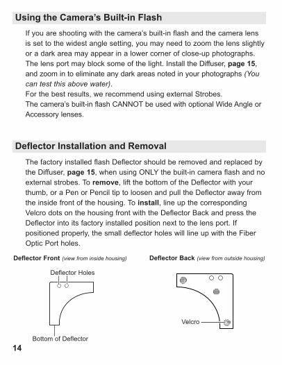
Deflector Installation and RemovalThe factory installed flash Deflector should be removed and replaced bythe Diffuser, page 15, when using ONLY the built-in camera flash and noexternal strobes. To remove, lift the bottom of the Deflector with yourthumb, or a Pen or Pencil tip to loosen and pull the Deflector away fromthe inside front of the housing. To install, line up the correspondingVelcro dots on the housing front with the Deflector Back and press theDeflector into its factory installed position next to the lens port. Ifpositioned properly, the small deflector holes will line up with the FiberOptic Port holes.
Deflector Front (view from inside housing)
Velcro
Bottom of Deflector
Deflector Holes
Deflector Back (view from outside housing)
14
15
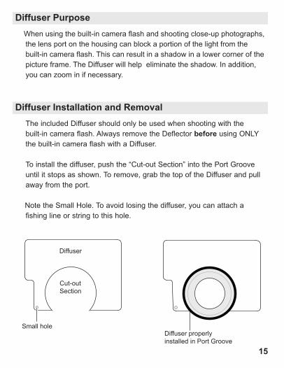
When using the built-in camera flash and shooting close-up photographs,the lens port on the housing can block a portion of the light from thebuilt-in camera flash. This can result in a shadow in a lower corner of thepicture frame. The Diffuser will help eliminate the shadow. In addition,you can zoom in if necessary.
The included Diffuser should only be used when shooting with thebuilt-in camera flash. Always remove the Deflector before using ONLYthe built-in camera flash with a Diffuser.
To install the diffuser, push the “Cut-out Section” into the Port Grooveuntil it stops as shown. To remove, grab the top of the Diffuser and pullaway from the port.
Note the Small Hole. To avoid losing the diffuser, you can attach afishing line or string to this hole.
Diffuser properlyinstalled in Port Groove
Diffuser Installation and Removal
Diffuser Purpose
Diffuser
Cut-out Section
Small hole
16
As soon as you enter the water, take a moment and check to see thatthe housing is properly sealed. We recommend you first water test thehousing with no camera inside to assure a safe and watertightenvironment.Next, check to see if there are any bubbles on the face of the lens port.If there are, take your finger and remove them. If there are bubbles onthe lens port they can produce soft focus spots in your photos or video.
Entering the Water
Recommended Accessories
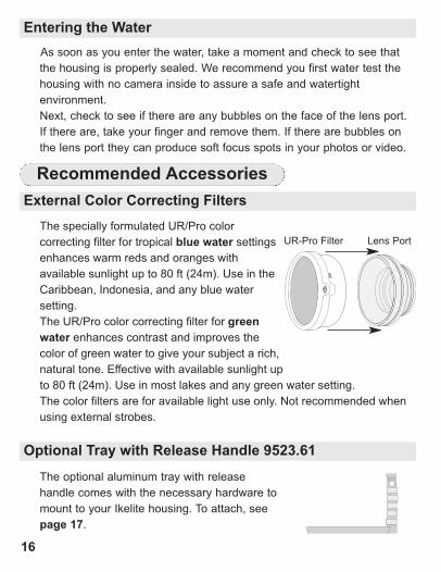
The specially formulated UR/Pro colorcorrecting filter for tropical blue water settingsenhances warm reds and oranges withavailable sunlight up to 80 ft (24m). Use in theCaribbean, Indonesia, and any blue watersetting.The UR/Pro color correcting filter for greenwater enhances contrast and improves thecolor of green water to give your subject a rich,natural tone. Effective with available sunlight upto 80 ft (24m). Use in most lakes and any green water setting. The color filters are for available light use only. Not recommended whenusing external strobes.
UR-Pro Filter Lens Port
Optional Tray with Release Handle 9523.61
The optional aluminum tray with releasehandle comes with the necessary hardware tomount to your Ikelite housing. To attach, seepage 17.
External Color Correcting Filters
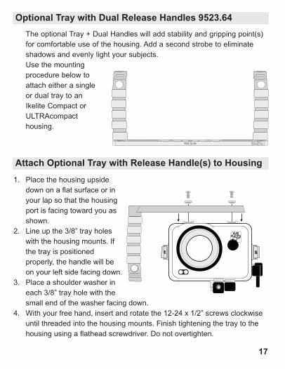
The optional Tray + Dual Handles will add stability and gripping point(s)for comfortable use of the housing. Add a second strobe to eliminateshadows and evenly light your subjects. Use the mountingprocedure below toattach either a single or dual tray to an Ikelite Compact orULTRAcompacthousing.
1. Place the housing upside down on a flat surface or inyour lap so that the housing port is facing toward you as shown.
2. Line up the 3/8” tray holes with the housing mounts. If the tray is positioned properly, the handle will be on your left side facing down.
3. Place a shoulder washer in each 3/8” tray hole with the small end of the washer facing down.
4. With your free hand, insert and rotate the 12-24 x 1/2” screws clockwise until threaded into the housing mounts. Finish tightening the tray to the housing using a flathead screwdriver. Do not overtighten.
Attach Optional Tray with Release Handle(s) to Housing
Optional Tray with Dual Release Handles 9523.64
MADE IN USA
17
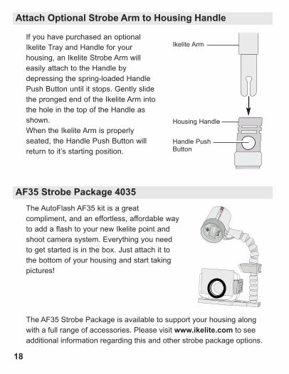
The AutoFlash AF35 kit is a greatcompliment, and an effortless, affordable wayto add a flash to your new Ikelite point andshoot camera system. Everything you needto get started is in the box. Just attach it tothe bottom of your housing and start takingpictures!
The AF35 Strobe Package is available to support your housing alongwith a full range of accessories. Please visit www.ikelite.com to seeadditional information regarding this and other strobe package options.
ikelite
35AF
ikelite
AUTO
FLAS
H
If you have purchased an optionalIkelite Tray and Handle for yourhousing, an Ikelite Strobe Arm willeasily attach to the Handle bydepressing the spring-loaded HandlePush Button until it stops. Gently slidethe pronged end of the Ikelite Arm intothe hole in the top of the Handle asshown. When the Ikelite Arm is properlyseated, the Handle Push Button willreturn to it’s starting position.
Ikelite Arm
Handle Push Button
Housing Handle
Attach Optional Strobe Arm to Housing Handle
AF35 Strobe Package 4035
18

19
The housing port is designed to accept 3.0-inch diameter color filters,and wide angle or macro options with 67mm threads. Light is absorbedvery quickly as it passes through water. A subject will look darker, lesscolorful and somewhat grainy when viewed through even a few feet ofwater. The addition of a compatible wide angle accessory expands thecamera's field of view underwater, providing the opportunity to get asclose as possible to the subject and reduce the amount of water lightpasses through. We recommend the Ikelite W30 Wide Angle Lens or INON UWL-H100Wide Angle Lens for excellent edge sharpness with minimal vignetting(dark shadows in the corners of the image). Vignetting may be eliminatedby either zooming slightly or cropping the image in post-production.
Notes: The camera’s built-in flash cannot be used with External AccessoryLenses.
Bayonet mount lenses cannot be used with this housing.
Please visit www.ikelite.com for additional information.
Ikelite 6430 W30 Conversion Lens
External Accessory Lenses
Recommended Accessories - continued
Video LightingExternal video lights such as the 2101 Vega Video + Photo Light addcolor when using the video/movie mode of your camera. Primary videolights are specially color balanced to provide natural tones.
Additional Accessories- 2602.3 Quick Release Handle Kit for GoPro
- Gamma LED Focus/Flashlight
A full range of accessories are available to support your housing. Pleasevisit www.ikelite.com to see the most current information aboutrecommended accessories for your housing.
20
Maintenance
Ikelite provides silicone lubricant with the housing. We recommend you useonly Ikelite lubricant on Ikelite products. Other brands may cause the mainhousing o-ring to swell and not seal properly, or the plastic components tocrack.Use only enough lubricant to lightly cover the main housing o-ring orlubricate a sticky control. Wipe off any excess lubricant with a cleancloth. Lubricant is not a sealant; it is used to reduce friction. Excessivelubricant can collect sand and dirt which may interfere with propersealing.CAUTION:Never use spray lubricants as the propellant ingredient can cause
Treat the glass in the lens port as a camera lens. After use, rinse andgently dry the outside lens port to avoid water spotting. To clean, use amild soap solution or lens cleaner. It is NOT necessary to remove thePort for cleaning. Do not rinse the inside the Port. Do not use alcohol or window cleaner on the Lens Port.
Lens Port
Lubricant
21
When storing the housing, remove the main housing o-ring. Lightlylubricate the o-ring until it appears shiny and place in a small resealableplastic bag. Use only Ikelite lubricant. Place the bag inside the housingand store until needed.
O-ring Storage
Your Ikelite Digital Housing should be given the same care and attentionas your other photographic equipment. In addition to normalmaintenance, we recommend that the housing be returned to Ikeliteperiodically to be checked and water pressure tested.
- Do Not leave the camera and housing in direct sunlight for prolongedperiods. Heat may damage the camera.
- Do Not ship the camera in the housing.- Before using the housing, always check the tightness of the set screw in
each control knob. Check each control gland penetrating the housing tomake sure they are tight. There is a slight chance that either couldvibrate loose during travel.
- Keep the main housing o-ring clean and lightly lubricated. To lubricate,remove the o-ring from the back. Put a small amount of lkelite lubricanton your fingers. Pull the o-ring through your fingers to apply a thincoating of lubricant. Only apply enough lubricant to make the o-ring feelslick. Do Not stretch the o-ring. This light coating of lubricant will helpto keep the o-ring from drying out and will help to show a dark sealingline when the housing back is properly sealed.
- Keep the area where the o-ring fits and the sealing surface of thehousing clean.
- Rinse the housing exterior thoroughly in freshwater after each saltwateruse. Depress push buttons repeatedly in freshwater to eliminate trappedsaltwater. Dry with a soft cloth. Dry lens port to eliminate water spotting.After several uses in saltwater, soak the housing exterior in a mild soapsolution; rinse and dry before storing. When storing the housing, removethe back o-ring, lightly lubricate, and place in a plastic bag. Place theplastic bag with o-ring inside the housing for safe keeping.
- If removing a housing push button, Do Not re-use the E-clip. ContactIkelite for replacement E-clips (part 0319.12).
- Leave lid snaps in the open position when not using the housing forextended periods.
Housing Maintenance
22
23
Ikelite controls are designed to provide years of reliable service withminimal maintenance.
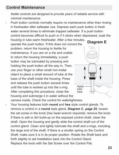
- Push button controls normally require no maintenance other than rinsingin freshwater after saltwater use. Depress each push button in freshwater several times to eliminate trapped saltwater. If a push buttoncontrol becomes difficult to push or if it sticks when depressed, soak thehousing in luke warm freshwater. After a few minutes,operate the push button. If this does not correct theproblem, return the housing to Ikelite formaintenance. If you are on a trip and unableto return the housing immediately, a pushbutton may be lubricated by pressing andholding the push button all the way in. Then,use your finger or other small non-metalobject to place a small amount of lube at thebase of the shaft inside the housing. Pressand release the push button several timesuntil the lube is worked up into the o-ring.After completing this procedure, close thehousing and submerge it in water without thecamera i nside. Check the control for watertightness.
- Your housing features both round and hex style control glands. Toremove a control in a round style gland, Diagram C, page 25, loosenthe set screw in the knob (hex head wrench required); remove the knob.If there is salt or dirt build-up on the exposed control shaft, clean theshaft. Open the housing and gently slide the control shaft out of thecontrol gland. Clean and lightly lubricate the shaft and o-rings, includingthe large end of the shaft. If there is a shutter spring on the ControlShaft, make sure it is in its proper position. Rotate the Shaft back andforth slightly to aid installation back into the Control Gland. Replace the knob with the Set Screw over the Control Flat.
Control Maintenance
Apply lubehere
Diagram E

24
Control Maintenance - continued
The Set Screw in the knob should be tightened down against the flatarea on the Control Shaft so the knob does not turn on the shaft.
- Some of the controls have long shafts and feature a hex style controlgland. These controls can be pulled out, exposing the shaft, Diagram D,page 25. To lubricate the control, gently pull on the knob until thestainless steel shaft is exposed. Lightly lubricate the shaft, then movethe shaft in and out several times. This will lubricate the x-ring in theIkelite control gland. This should be done before using the housing aftera prolonged storage period, or once a week when the housing is inconstant use.
- Some controls have a short shaft and cannot be pulled out exposing theshaft for lubrication. To remove a control, Diagram E, page 25, loosenthe set screw in the knob (hex head wrench required); remove the knob.If there is salt or dirt build-up on the exposed control shaft, clean theshaft. Open the housing and gently slide the control shaft out of thecontrol gland. Clean and lightly lubricate the shaft, including the end ofthe shaft. Slide the shaft back into the control gland and gently slide theshaft back and forth a few times without fully removing the shaft from thegland. Replace the knob noting the flat area on the shaft. The set screwin the knob should tighten down against the flat area on the control, sothe knob does not turn on the shaft. Close housing without a camerainside and water pressure test in a bathtub or swimming pool. Rotate*the knobs to make sure the housing is watertight and the gland wasinstalled properly. Check all controls while the housing is submerged.
- In the unlikely event one of the control shafts sticks or becomes difficultto operate, you can remove the control from the housing and lubricate it,or return the housing to Ikelite for maintenance. *Caution: If your housing has a shutter spring, DO NOT rotate theshutter control more than 1/16th of a rotation, otherwise, you mayaccidentally bend the shutter spring or cause the spring to “pop off” thecontrol shaft.
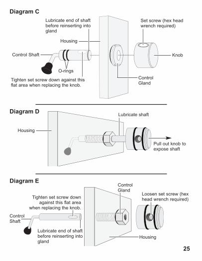
Set screw (hex headwrench required)
Tighten set screw down against thisflat area when replacing the knob.
Housing
Control Shaft
Lubricate end of shaftbefore reinserting intogland
Diagram C
O-rings
Knob
Control Gland
Housing
Lubricate shaft
Pull out knob toexpose shaft
Diagram D
Diagram E
Loosen set screw (hex head wrench required)Tighten set screw down
against this flat areawhen replacing the knob.
Housing
Control Gland
Control Shaft
Lubricate end of shaftbefore reinserting intogland
25

26
Photo Tips- The number one rule in underwater photography is to eliminate as much
water between the camera and subject as possible. Get as close as youcan to the subject, then use the zoom. If you are using flash for stillphotos, subjects beyond 6 ft (1.8m) will not have much color regardlessof strobe power.
- Photograph in clear water; do not stir up the sand or silty bottom. Ifbackscatter becomes a problem in the environment you arephotographing, an external flash will help eliminate much of thebackscatter.
- Many digital cameras have a slight lag time between when you pressthe shutter release button and the camera actually takes the picture.Hold the housing steady a second or two after pressing the shutterrelease button.
- Do not shoot down on subjects as they will quite often blend into thebackground and be difficult to see in the photograph. Shoot subjectsstraight on or shoot up at a slight angle using the blue water as acontrasting background.
- When using daylight or flash, if your camera consistently over orunderexposes the image, you may want to adjust your camera’sexposure compensation or flash exp. comp. settings.
- If you error in exposure, it is better to have the image slightlyunderexposed rather than overexposed. An overexposed image ismissing color information which cannot be adjusted in a photoprocessing program. A slightly underexposed image has colorinformation that can be adjusted.
- It is important to respect all living creatures underwater, includingpeople, marine life, and coral. While we encourage people to get closeto their subjects when taking a photograph, they should not touch, lie on,or in any way disturb the things they find underwater.
27
Troubleshooting
Push buttons orcontrols are sticky orhard to operate
- Remove the camera and rinse the closed housing in freshwater. Vigorously press each push button in and out several times to release any trapped saltwater or debris.- Press a sticky push button all the way in and place a small amount of lube on the small end of the push button shaft at it’s base. Release and operate the push button several times to distribute the lube, Diagram E, page 23.- If a larger gland style control is sticky, grab the control knob, pull it out, and then push back in. If still sticky, see the Control Maintenance section, page 24.
- Return housing to Ikelite for routine maintenance.
Problem Solution
Image isover/underexposed,or a corner of theimage is dark
- Check that the built-in flash or external strobe is firing when taking a picture. Camera flash should be forced “on.”- When using an external strobe, make sure it is turned on, set properly, and its battery is charged.- Make sure the diffuser is installed when you are NOT using an external strobe.- Check any corded connection points. - Change camera shutter speed or aperture.- Move closer to or further away from the subject.- Adjust Flash Exposure Compensation .- For extreme overexposure turn on the ND neutral density filter (if available).
28
Camera does nottake a picture
Problem Solution
Fogging occurs onthe Lens Port
- Humid air is trapped inside the housing. The camera produces heat and may condense any trapped moisture forming fog on the lens port. Close the housing in an air-conditioned room or vehicle, or in front of an air-conditioner. - The housing should not be in direct sunlight for an extended period of time.- Purchase desiccant packs also known as moisture munchers from a local camera store. Place one or two new packs in your housing before each day of diving.- If moisture or water droplets are present around the controls or sealing areas, return the housing to Ikelite for evaluation. - Clean the main housing o-ring and sealing surface of the housing.
- Make sure the camera is mounted properly in the housing and controls are out of the way.- Main housing o-ring is not seated properly.- Hotshoe cord is in the way (if applicable).- Control Ring not engaging housing gear properly.
Housing is hard toclose
- Install a fully charged battery.- There is not enough available light for the camera to properly focus. Add a focusing light or strobe with a built-in focusing or video light to yoursystem.
- Select a center focus point in your camera menu.- Return Zoom control to the “disengaged” position, see Zoom Control Use, page 12.

29
Water enters thehousing
- Remove, clean and properly lubricate the main o-ring.- Look for hair, dirt, or foreign debris crossing the o-ring seal.- Reassemble the housing without a camera installed and immerse in water.- Return housing to Ikelite for evaluation.
Problem Solution
Pictures are too blueor too green
- Use custom (manual) white balance. Reset for each working depth or when attaching a color correcting filter to the camera lens.- Add an external strobe.- Move in closer to your subject when taking a picture.- Add an optional color correcting filter to the Housing Port.
- 0184.2 ........Silicone Lubricant 2cc Reclosable Tube- 0200............Port cover - 0109............Main o-ring - 9523.10 ......Tray Hardware- 0945.18 ......Hex Head Wrench for control knobs- 0945.11 ......Hex Head Wrench for Control Ring small nylon set screws
Spare Parts (available through Ikelite or any Ikelite Dealer)
30
This Ikelite product is warranted against any manufacturing defects for aperiod of one (1) year from the original date of purchase. Defectiveproducts should be returned to Ikelite postage paid. Ikelite will, at its solediscretion, repair or replace such products, and will return to customerpostage paid. All other claims of any nature are not covered. Except asmentioned above, no other warranty expressed or implied applies to thisIkelite product.
Limited Warranty
Customer SupportPlease read the troubleshooting section of this instruction manual beforecontacting Ikelite Customer Support.
Ikelite Underwater SystemsService Department50 West 33rd St.Indianapolis, IN 46208 USA
Email: [email protected]: 317-923-4523
31
Ikelite is most interested in performing any service to ensure that allproducts perform as intended. Evidence of purchase date must beprovided to obtain warranty service.No prior authorization is required. You may return directly to us orthrough your dealer. Please include a brief description of the problem,any relevant email correspondence, and/or instructions on what youwant us to do. Always include name, shipping address, email address,and phone number inside of the package. Send postage paid to:
Ikelite Underwater SystemsAttention: Service Department50 West 33 StreetIndianapolis, IN 46208 USA
No reimbursements for postage paid will be issued.
You may also want to insure the package.
Returning Products For Service
For the separate international customs documentation form that youcomplete to accompany the shipment, please state or designate that theenclosed products were originally manufactured in the USA and arebeing returned to the manufacturer for repair service. Value of theequipment listed for customs purposes should be zero.
Returning Products for Service - outside the United States

Ikelite Underwater Systems50 West 33rd Street
Indianapolis, IN 46208 USA
www.ikelite.com
Product RegistrationPlease go to www.ikelite.com to register your Ikelite housing within 15days of purchase.
6146.07_Canon_G7X_1-1114
© 2014 Ikelite Underwater Systems