imiii f~lflllll=414 - defense technical information center · 2.1 compositional variability ......
TRANSCRIPT
AD-A264 414IMIII i f~lflllll=
WL-TR-92-4090
USE OF TITANIUM CASTINGS WITHOUT A CASTING FACTOR
Dr. Dianne ChongMcDonnell Douglas Missile Systems CompanyPO Box 516St Louis MO 63166-0516
September 1992
Final Report for Sept 26 89 - Sept 30 92
Approved for Public Release; Distribution is Unlimited
=-.-..
SDTI CELECTF
S MWAY 1q. i=
Materials DirectorateWright LaboratoryAir Force Materiel CommandWright-Patterson Air Force Base, Ohio 45433-7718
j4i I•I1".193-10807

NOTICE
When Government drawings, specifications, or other data are used for any purposeother than in connection with a definitely Government-related procurement, theUnited States Government thereby incurs no responsibility nor any obligationwhatsoever. The fact that the government may have formulated, or in any waysupplied the said drawings, specifications, or other data, is not to be regarded byimplication or otherwise as in any manner construed, as licensing the holder or nayother person or corporation, or as conveying any rights or permission tomanufacture use, or sell any patented invention that may in any way be relatedthereto.
This report is releasable to the National Technical Information Service (NTIS). AtNTIS, it will be available to the general public, including foreign nations.
This technical report has been reviewed and is approved for publication.
TEW.T C)0N THEODORE I- F' AINHART, ChiefEngineering & De n Data Materials Engineering BranchMaterials Engineering Branch Systems Support Division
FOR THE COMMANDER
THOMAS D. COOPER, "hfSystems Support DivisiaMaterials DirectorateWright Laboratory
If your address has changes, if you wish to be removed from our mailing list, or ifthe addressee is no longer employed by your organization please notify WL/MLSEBLDG 652, 2179 TWELFTH ST STE 1, WPAFB OH 45433-7718 to help usmaintain a current mailing list.
Copies of this report should not be returned unless return is required by securityconsiderations, contractual obligations, or notice on a specific document.
1. A0CV U10 GNLMT P"., ,,Wm . U •m",E SPO ET E AND DATES COVERED
September 1992 Final Report 26 Sept 1989- 30 Sep 19924. TTL AMS VIBTLI! L PFUNDNONUMBI
Use of Titanium Castings Without a Casting Factor C-F33615-89-C-5621PE-62102F
An.... PR-2418fl Inonp TA-04
Dianne Chong WU-73
.PIRPORAOG OVAOANATMAI0N"N() AMS AD011ongEl L. UPERORSOG GWAI NIZ1EPORT NUMM
McDonnell Douglas Missile Systcuis CompanyP.O. Box 516St. Louis MO 63166-0316
I. 8I"SOOeONG /MOMTOIUNO AwCY Nm" ANS ADODSS(E 10. SPONsOI"/ MONTOAINMaerials Directorate AGENCY REPORT NUMBER
Wright Laborato"y (WI.MLSE) WL-TR-924090Air Force Materiel CommandWright-Patterson Air Force Base OH 45433.7718(Steven R. Thompson; 513-255-5063)
11. SUPPLEMENTARV NOTES
12L. DISTIBUTION / AVAIABLITY STATEMENT a6. DISTRIOUTON0 CODE
Approved for Public Rcleasc: Distribution is Unlimited
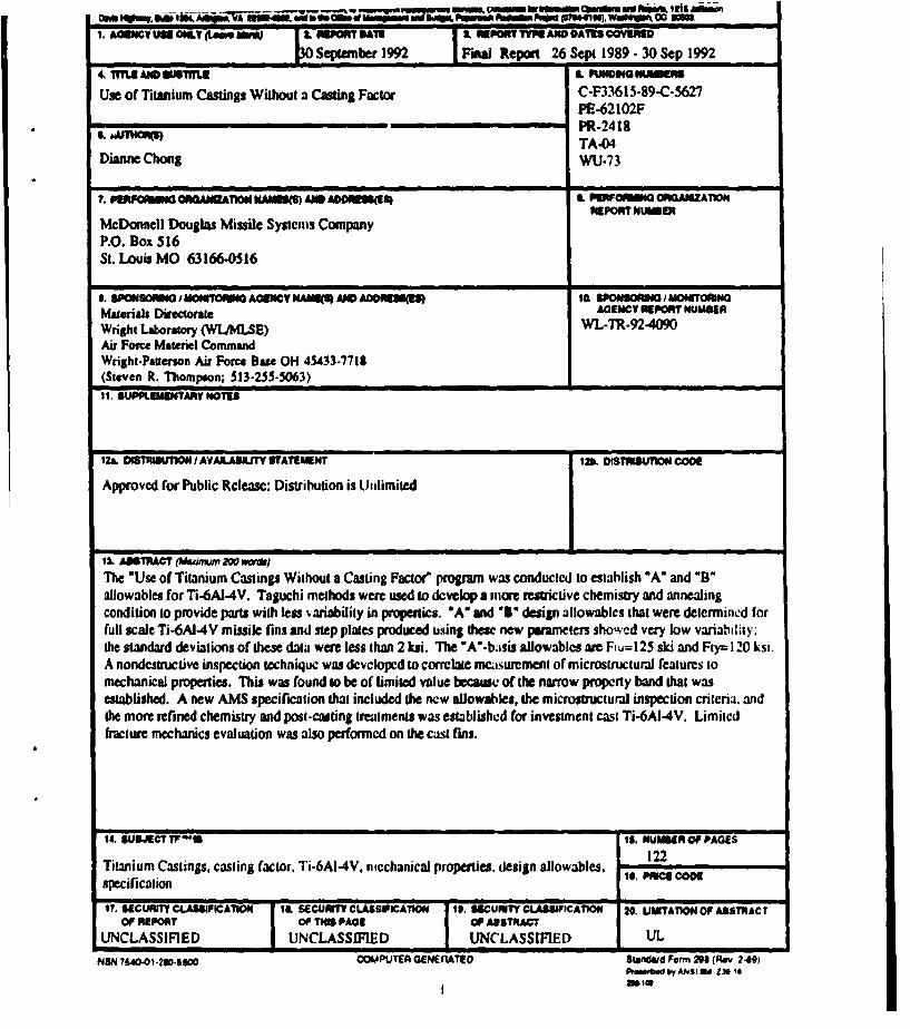
1i. ABSTRACT (Maidmum 2W0 wo)
The "Use of Titanium Castings Without a Casting Factor" program was conducted to establish "A" and "B"allowables for Ti.6A1-4V. Taguchi methods were used to develop a more restrictive chemistry and annealingcondition to provide parts with less variability in properties. "A" and "'" design allowablcs that were determined forfull scale Ti-6A1-4V missile fins and step plates produced using these new pmmasneers showcd very low variability:the standard deviations of these data were less than 2 ksi. The "A"-basis allowables are Ftu=125 ski and Fry" 120 ksi.A nondestructive inspection technique was dcvcloped to correlate m•csurcment of microstructurm features tomechanical properties. This was found go be of limited value because of the narrow property band that wasestablished. A new AMS specification that included the new allowables, the microstructural inspection criteria, andthe more refined chemistry and post-casting treatments was established for investment cast Ti-6AI-4V. Limitedfracture mechanics evaluation was also performed on the cast fins.
14. GdECT TF*4 It. NUM•ER OF PAGES
Titanium Castings, casting factor. Ti-6AI-4V. mcchanical properties, design allowables. 122
specification Is. C
17. SECURITY CLASSPICATION I&, SECUITYrCLASSI1PATION It. SECURITY CLAAIICATION 20. UMITA"ION OF ABSTRACTOF REPORT OF THIS PAE OP ANSTRACT
UNCLASSIFIED UNCLASSIFIED UNCLASSIFIED UL
NSN 76.40-1-20-5500 COMPUTEA GENErFATED Standdwd Form 290 (Rey 240)
2*1e0V1 dUE*31

FOREWORD
This program was conducted by the McDonnell Douglas Missile SystemsCompany (MDMSC) in cooperation with Scldosser Casting Company underContract Number F33615-89-C-5627. Under this effort "A" and "B" designallowables were determined fDr Ti-6AI-4V castings. A new microstructuralinspection techniques and a new AMS specification were established forinvestment cast Ti-6Al-4V.
Mr. Steven R. Thompson managed the program for Wright Laboratory. Hisguidance on the program is greatly appreciated. Funding for the program wasprovided by Wright Laboratories Materials Directorate.
We are also grateful for the support provided by the members of the MIL-HDBK-5 Titanium Casting Task Group, for their inputs and support of thisprogram. Their guidance was invaluable to the program.
DTIC Q!ALMT r1-ki'ECTED 8
&o@sssion @o0
3715 GRA&1DTIC TAB 0Una•,usno ed 0JuJt l ct erion-
By-Distr 'Ibu ti/
Avail bllt C0od4l
IAVSI 1 d/otDist 0pealI
ViIi

CONTENTS
SPAOE
FOREW ORD ....................................... iii
LIST CF T'iGUL R .................................. vii
LIST OF TABLES ................................... ix
I INTRODUCTION AND SUMMARY .................... 11.1 BACKGROUND .................................... 21.2 PROGRAM PHASES ................................ 5
2 CONTROL OF VARIABILITY ........................ 62.1 COMPOSITIONAL VARIABILITY .................... 62.2 POST-CASTING TREATMENT ........................ 10
3 PREPRODUCTION PART ANALYSIS .................. 133.1 MECHANICAL PROPERTY TESTING .................. 133.2 NONDESTRUCTIVE INSPECTION .................... 19
4 ESTABLISHMENT OF SPECIFICATION ................ 24
5 "A' AND "B" ALLOWABLES ......................... 265.1 ALLOWABLES DETERMINATION .................... 265.2 REDUCED RATIOS ..... 285.3 NONDESTRUCTIVE INSPECTION .. .......... 29
6 DAMAGE TOLERANCE ............................. 326.1 FRACTURE TOUGHNESS ............................ 326.2 FATIGUE CRACK GROWTH ......................... 35
7 CONCLUSIONS AND RECOMMENDATIONS ............ 40
8 REFERENCES ...................................... 42
V

CONTENTS (CONT'i))
APPENDICES ...................................... 45
APPENDIX A: CONTROL OF VARIABILITYTAGUCHI ANALYSIS .............................. 45
APPENDIX B: PREPRODUCTION PART ANALYSIS ...... 60
APPENDIX C: PROPOSED AMS SPECIFICATrION FORTITANIUM ALLOY CASTINGS, INVESTMENT 6AL-4V ... 64
APPENDIX D: CAST TI-6AL-4V PRODUCTIONFIN ANALYSIS, MECHANICAL PROPERTY DATA,MICROSTRUCTURAL NDI DATA, "A" AND 'B"ALLOWABLE ANALYSIS ............................ 77
APPENDIX E: FRACTURE MECHANICS DATA .......... 97
vi
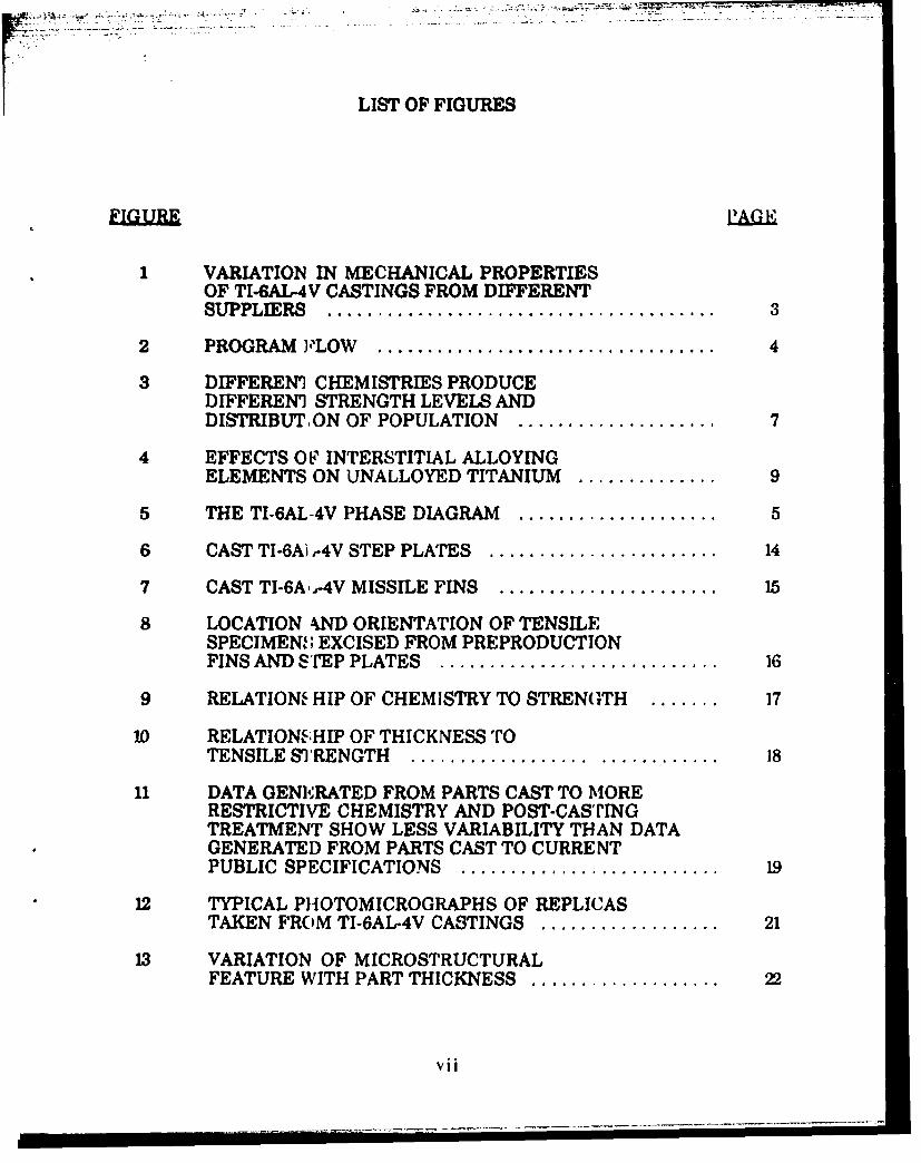
LIST OF FIGURES
1 VARIATION IN MECHANICAL PROPERTIESOF TI.6AL-4V CASTINGS FROM DIFFERENTSUPPLIERS ....................................... 3
2 PROGRAM 'LOW .................................. 4
3 DIFFEREN1 CHEMISTRIES PRODUCEDIFFERENI STRENGTH LEVELS ANDDISTRIBUTON OF POPULATION ..................... 7
4 EFFECTS OF• INTERSTITIAL ALLOYING
ELEMENTS ON UNALLOYED TITANIUM .............. 9
5 THE TI-6AL-4V PHASE DIAGRAM .................... 5
6 CAST TI-6A) ,-4V STEP PLATES ....................... 14
7 CAST TI-6A,-4V MISSILE FINS ...................... 15
8 LOCATION kND ORIENTATION OF TENSILESPECIMEN'; EXCISED FROM PREPRODUCTIONFINS AND ST'EP PLATES ............................ 16
9 RELATIONS HIP OF CHEMISTRY TO STRENGTH ....... 17
10 RELATION'.HIP OF THICKNESS TOTENSILE S)'RENGTH .................. ............ 18
11 DATA GENERATED FROM PARTS CAST TO MORERESTRICTIVE CHEMISTRY AND POST-CASTINGTREATMENT SHOW LESS VARIABILITY THAN DATAGENERATED FROM PARTS CAST TO CURRENTPUBLIC SPECIFICATIONS .......................... 19
12 TYPICAL PHOTOMICROGRAPHS OF REPLICASTAKEN FROM TI-6AL.-4V CASTINGS .................. 21
13 VARIATION OF MICROSTRUCTURALFEATURE WITH PART THICKNESS ................... 22
vii

LIST OF FIGURES (CONT'D)
- PAG
14 SIZES OF THE MICROSTRUCTURAL FEATURESVARY LITTLE OVER THE NARROW PROPERTYRANGE SEEN IN THESE CASTINGS ................... 23
15 PRODUCTION FINS FROM SUPPLIER 2 ................ 27
16 COMPRESSION, BEARING, AND SHEARSPECIMENS FROM TI-6AL-4V CAST[NGS .............. 30
17 SUMMARY OF ALLOWABLES FOR CAST TI-6AL-4V ..... 31
18 COMPACT TENSION SPECIMENS AND BENDSPECIMENS USED FOR FRACTURETOUGHNESS ASSESSMENT .......................... 33
19 FRACTURE TOUGHNESS DATA FROM THE COMPACTTENSION SPECIMENS ARE COMPARABLE TOLITERATURE VALUES (REFERENCE 32) ............... 34
20 FATIGUE CRACK GROWTH SPECIMEN ............... 36
21 FATIGUE CRACK GROWTH RATE AS A FUNCTIONOF STRESS INTENSITY FACTOR FOR ALL THREESPECIMENS TESTED ................................ 37
22 COMPARISON OF FATIGUE CRACK GROWTH DATAWITH LITERATURE CITATIONS (REFERENCE 32) ....... 38
23 CRACK GROWTH VERSUS CONSTANT-AMPLITUDESTRESS CYCLES FOR THREE TI-6AL-4V CAST FINS ..... 39
viii

LIST OF TABLES
TARL.E PAGE
1 "A" AND "B" ALLOWABLES CORRESPONDINGTO CURVES IN FIGURE 3 ........................... 7
2 PROPOSED CHEMISTRIES FOR TI-6AL-4V CASTINGS ... 8
3 CONTRIBUTION OF ALLOYING ELEMENTS TOMECHANICAL PROPERTY VARIABILITY ............ 8
4 PROGRAM CHEMISTRY ............................ 10
5 ACTUAL CI{EMISTRIES OF PREPRODUCTION PARTS .. 17
6 MICROSTRUCTURAL FEATURES - MAXIMUM LIMITS.23
"7 COMPARISON OF FEATURES OFSPECIFICATIONS FOR CAST TI-6AL-4V .............. 25
8 "A" AND "B;" ALLOWABLES ......................... 28
9 REDUCED RATIOS FOR TI-6AL-4V CASTINGS ......... 29
10 FRACTURE TOUGHNESS TESTS ..................... 34
11 R-CURVE MEASUREMENTS ........................ 35
12 FATIGUE CRACK GROWTH CONDITIONS ............ 36
ix

SECTION 1
INTRODUCTION AND SUMMARY
Casting has been demonmtrated to be a cost-effective means ofmanufacturing aerospace parts compared to other fabrication processessuch as machining or forging. The casting process produces net or nearnet shape parts that require little or no machining. For titanium alloyscastings are particularly cost-effective for several reasons. Since the rawmaterial cost of titanium is high, efficient use of the raw material as incastings results in little waste. Using traditional methods to machinetitanium is expensive. Elimination of machining would further reducecosts.
Although castings have been found to be cost-effective, their usage incritical aircraft structures is limited due to the imposition of a margin ofsafety (i.e., casting) factor. In early casting technology, poor controls overthe material composition resulted in parts with entrapped gas orinclusions. Lack of process control produced castings with shrinkage,cold-shuts, and hot tears. Many parts had coarse, nonuniformmicrostructure and chemical segregation. These defects causedvariabilities in the mechanical properties of castings. This led to theinstitution of an added margin of safety for castings, or a casting factor,that is still used in the design of cast components despite theadvancements that have been made in casting technology that haveincreased the reliability and quality of parts.
Foundries have focussed on several parameters in order to improvethe quality of castings. Refinement of chemistries has been performed toincrease consistency in processing as well as in the final product.Analysis of casting design has provided information for the optimization ofgating and mold fill to prevent the formation of flaws during casting and toimprove producibility. Heat treatment of castings has been developed tomodify microstructures to improve properties as verified by tests ofseparately cast bars or prolongations. Extensive nondestructive inspectiontechniques have been developed to verify quality in castings. Thesetechniques and inspection criteria have been tailored to the criticality ofcastings in use. While the better inspection methods increase confidencein the quality of the parts being used, they also add to the cost of usingcastings. Despite all these improvements in foundry practice, the processcontrols are not well enough established to permit the establishment ofdesign allowables.
I 1

1.1 BACKGROUND
Aircraft companies have been reluctant to use castings (primarilyaluminum) due to their inconsistent mechanical properties and quality.To compensate for the scatter in properties, a margin of safety (i.e., acasting factor) of 1.33 was defined for missiles (Reference 1) and aircraft(Reference 2). During the 1960s, aluminum foundries demonstrated thatthe property scatter could be reduced by providing better control of theprocess. To eliminate the uncertainty that properties of separately cast testbars did not reflect those of castings, strength was verified usingspecimens excised from parts. While the use of separately cast barsprovides a good means of checking chemistry and heat treatmentresponse, it is not representative of the properties of the part since thesolidification environment is different. In 1970, MIL-A-21180 (Reference 3)was issued and addressed the problem of variability in properties byrequiring more detailed inspection criteria. Even with improvements infoundry practice, variability in mechanical properties was still consideredexcessive. In 1985 acceptance criteria based upon measurement ofdendrite arm spacing (DAS) of aluminum castings was established(Reference 4). Subsequently, the Society of Aerospace Engineers (SAE)issued an Aerospace Recommended Practice, ARP 1947, (Reference 5)describing the procedure for determining DAS and relating it to tensilestrength and also issued a material specification, AMS 4241 (Reference 6),that specified a more restrictive chemistry for aluminum alloy 357.
Despite the advances that have been made in titanium foundrytechnology, there is a reluctance to eliminate the casting factor because ofthe history of property variability in aluminum castings. In titaniumalloys, hot isostatic pressing and appropriate heat treatment have beenshown to offer the potential of near-wrought properties, including fatigue-resistance and ductility. For these reasons and because of the costeffectiveness of using these castings, there has been an increased interestin using and establishing design allowables for these parts. In response tothis need, in 1986, the Military Handbook 5 Coordination Committeeestablished an ad hoc committee to compile data from investment cast Ti-6AI-4V for the purpose of determining "A" and "B" design allowables.Data from suppliers and users supplied to the Titanium Casting TaskGroup showed that investment cast Ti-6AI-4V parts supplied to theaerospace industry could not be represented by a single set of "A" and "B"design allowables (Reference 7).
Figure 1 demonstrates this point. This figure shows the mechanicalproperty distribution by supplier for an investment cast Ti-6AI-4V elevonhousing supplied to the Boeing Corporation (Reference 8). Data from eachsupplier can be represented by its own population distribution. Theimplication is that foundry practices significantly affect the variability ofmechanical properties in castings. However, the differences in propertiesin no way compromise the quality of the parts since mechanical properties
2

of the parts met the minimum values specified in the Boeing specification(BMS 7-181). Attempts to determine "A" and "B" basis design allowablesfrom data with such a large variation in properties would result inconservative values.
The Task Group concluded that the casting and processing of Ti-6A1-4V needed to be reduced to a standard practice that was tightlycontrolled by a specification in order to reduce the variability inmechanical properties. Only when the variability was reduced andmeaningful "A" and "B" allowables established, could reduction orelimination of the casting factor be considered.
30
C
20-
Frequency
percent A
10--
110 120 130 140 150
FTU. kh GOP34,OO4.16-v",
FIGURE 1. VARIATION IN MECHANICAL PROPERTIES OFTI-6AL-4V CASTINGS FROM DIFFERENT SUPPLIERS
The primary objective of our program was to establish meaningful"A" and "B" design allowables for Ti-6A1-4V castings. It is important toemphasize that this did not necessarily result in obtaining castings withthe highest properties, but rather the most consistent. We employed thestrategy of first reducing the variability in mechanical properties byimposing tighter restrictions on chemistry and post-casting treatment.We also utilized a microstructural nondestructive technique to verifyproperties of castings. Castings produced to these tightened parameterswould then be controlled by a new specification and a microstructuralnondestructive inspection technique. The technical program consisted ofthe following phases: control of variability, preproduction analysis,nondestructive inspection, specification establishment, establishment of
3

"A" and w" allowables. and damage to•isenae. Th program flow isshown in PFgure 2.
CONTROLOF
VARIABILITY
IFICAT IO
PPRODUCTION
PARTS
"A" AND "B" DAJ'IAGE1ALLOWABLES TOLERANCE
FIGURE 2. PROGRAM FLOW
4
SPECIFIC L-,,ATO

1.2 PROGRAM PHASES
In Phase I, we used Taguchi methods to determine the sources ofvariability in Ti-6AI-4V castings. The primary factors that wereinvestigated in this study were the chemical composition and post-castingtreatment. These factors were defined with the intent of producingcastings with small variability in mechanical properties.
In Phase II, we analyzed mechanical properties of preproductionmissile fins and step plates produced using the composition and post-casting treatment defined by the results of the Taguchi study. We alsoutilized a nondestructive inspection (NDI) technique developed by MDMSCto correlate physical and mechanical properties of castings with featuressuch as prior beta grain size, alpha colony size, and grain boundary alpha.
In Phase III, a new AMS specification was written to incorporatethe refined chemistry and post-casting treatment. Mechanical propertytesting of specimens from of step plates and preproduction fins was used toprovide "S" basis allowables.
In Phase IV, specimens from production lots of parts were tested todetermine "A" and "B" allowables for these castings. Compression,bearing, and shear properties were also determined for the establishmentof reduced ratios. These properties were used to revise the AMSspecification.
Finally, in Phase V, fracture mechanics testing of specimens fromthe castings was performed.
5

SECTION 2
CONTROL OF VARIABILITY
In Phase I, we utilized Taguchi methods to identify the causes of andminimise the variation in the tensile strength of titanium castings. Weapplied Taguchi analysis of means and variance methods to the test dataprovided by the Boeing Corporation as well as other available data. As aresult of this analysis, we were able to discern the individual effects ofchemistry, HIPing, and heat treatment on the average and variance of themechanical properties for Ti-WAI-4V castings. It was considered beyondthe scope of this program to include analysis of other factors such ascooling rates (due to differences in mold temperature prior to casting),weld repair conditions, and heat treatments above the beta transus.
2.1 COMPOSITIONAL VARIABILITY
In this task we used Taguchi methods to define compositional limitsfor Ti-6AI-4V castings to provide more consistent mechanical properties.The relative strengthening effect of each alloying element was taken intoaccount in our analysis. A detailed description of this analysis can befound in Appendix A.
Based on our findings, we felt that a tightening of allowablechemistry variations was feasible for the alloying elements in Ti-6AW-4V.Because of extensive experience obtained in the production of titaniumalloys over the last 30 years, control of alloy chemistry is fairly routine. Ofthe interstitials, carbon and nitrogen are usually not adjusted by theprimary metal supplier and tyically do not exceed 0.01 weight percent(w/o). Oxygen levels are usaly higher than those for carbon and nitrogenprimarily because the starting titanium sponge can contain oxygen levelsas high as 0.08 w/o. Melting operations conducted by titanium foundriestypically raise the oxygen content of the melt by approximately 0.02 w/o.With current commercial practice, therefore, it is possible to obtain atitanium alloy casting with well-controlled oxygen levels in the range 0.12-0.17 w/o.
As stated in Section 1, the intent of the program was to establishparameters to produce the most consistent properties and not necessarilythe highest average properties. An example of this is shown below.Differences in chemical composition that were still within the limits of thecurrent public specifications can produce variations in population
6

distributions (Figure 3). If we target a tighter chemical composition, weobtain the population labelled "minimum variance." The average strengthof the parts is approximately 134 kei. On the other hand, if our target wereto be a chemistry that would produce mazirnum average strength, theresultant mechanical properties would show a much larger spread invalues. The "A'- and "B"-basis allowables (Table 1) for each of thesegroups verify the influence that population distribution has upon allowablevalues.
so
Minimum Variance (Run 5)40 -
30-Frequoncy
percent Maximum Average (Run 4)
20-
10 -
0 1 _ _120 125 130 135 140 145 150
Uttimate Strength -kul OnhM4.toW . v,
FIGURE 3. DIFFERENT CHEMISTRIES PRODUCE DIFFERENTSTRENGTH LEVELS AND DISTRIBUTION OFPOPULATION
TABLE 1. "A" AND "B" ALLOWABLES CORRESPONDING TOCURVES IN FIGURE 3
jFALLaABOs•LE MINIMUM MARIM•JM
VARIANCE AVERAGE"A"-BSI_128 KffaI L117 KSI
"B"'BASIS 131 KSI 124
7

The Taguchi analysis of the Boeing data set identified an optimalchemistry for Ti-6AI-4V castings that would result in minimal variation inproperties. Our optimized chemistry is shown in Table 2 and is comparedto chemistries currently listed for Ti-6A14V castings. Ingot and castingsuppliers were asked to review the findings of the Taguchi analysis. Allfelt that the optimized chemistry was too restrictive and suppliedinformation that allowed us to define a chemical composition that was asclose to the optimized composition as possible and still consideredproducible by the casting suppliers without incurring a significant costpenalty.
TABLE 2. PROPOSED CHEMISTRIES FOR TI.6AL-4V CASTINGS
\ 5E /I NUM - t M I LOTI0- 1 *I l16 GdPP KIAI 3iPE- NA-
TI __t----__--_______5..8.0.4
V 3.6- 4 34-4.4 3.6. 4A , 38-4 4,41 -3A - 4.3 3. - 4AFe__ O,0_ _0.1 0 9.11 -0.21 0,10-0.1 0af i MAX 0.11 - 021C OAt~ 0.1M00 0.03 MAX 00 A O A ,1 ,3N 0.01. AAxL _ 0.0013 MAX 0.01 MAX o. I W MAX .ALMX"0 0Mu0mAX 0.13 0.16 0.12 - 0.16 o 0.13- 0.16 0.13 - 0.17 0.17• 020 0.18 - 020
0.13 J
yp~g 006 ~ 00 MAX 6AW 61 AX6NAUMSa OMIBWW• 0¢aAlfdlLIsof aall adalwf CW"WIP
OiGy "".10 -u 0"0.10) oy"1L t O wEAI) 60,10) n~~2
In our Taguchi analysis we also determined the contribution of eachelement to the variability of the mechanical properties. These data areshown in Table 3. The data indicate that aluminum is well-controlled
TABLE 3. CONTRIBUTION OF ALLOYING ELEMENTS TOMECHANICAL PROPERTY VARIABILITY
CONTITTRUTIONR TO VAIRIARITY OF:ELEMENT FTY FTU
A] 1.57% 1.82%
C 0.97% 6.79%H__ __ 15.08% 21._6_Fe 19.87%_ __ 17.84%N 7.65% 4.43%S15.25% 9.04%
TOTAL_ 60.39% 61.48%
I8
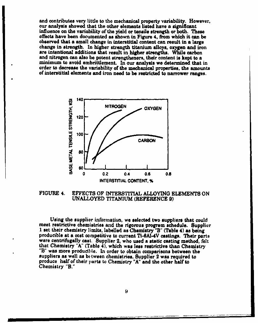
and contributes very little to the mechanical property variability. However,our analysis showed that the other elements listed have a significantinfluence on the variability of the yield or tensile strength or both. Theseeffects have been documented as shown in Figure 4, from which it can beobserved that a small change in interstitial content can result in a largechange in strength. In higher strength titanium alloys, oxygen and ironare intentional additions that result in higher strengths. While carbonand nitrogen can also be potent strengtheners, their content is kept to aminimum to avoid embrittlement. In our analysis we determined that inorder to decrease the variability of the mechanical properties, the amountsof interstitial elements and iron need to be restricted to narrower ranges.
-140NITROGEN OXYGEN
12
100-
680
0 0.2 0.4 0.6 0.8INTERSTITIAL CONTENT. %
FIGURE 4. EFFECTS OF INTERSTITIAL ALLOYING ELEMENTS ONUNALLOYED TITANIUM (REFERENCE 9)
Using the supplier information, we selected two suppliers that couldmeet restrictive chemistries and the rigorous program schedule. Supplier1 set their chemistry limits, labelled as Chemistry 'B" (Table 4) as beingproducible at a cost competitive to current Ti-6AI-4V castings. Their partswere centrifugally cast. Supplier 2, who used a static casting method, feltthat Chemistry "A" (Table 4), which was less restrictive than Chemistry"B" was more producible. In order to obtain comparisons between thesuppliers as well as b.tween chemistries, Supplier 2 was required toproduce half of their parts to Chemistry "A" and the other half toChemistry "B."

TABLE 4. PROGRAM CHEMISTRY
ELE•INT TAGUCHI CHEMISTRY CHEMISTRY
ANALYSIS "A" "B"amSB (MORE
R29tThlVE) REVISICTIVE)7i BALANCE BALANCE BALANCEAl 6.0426. 5.75 - F3_ 6.A - 6.4
V_ý 3.6 - 4.4 3.6 -4.5 - 3.6 - 4.4Fe 0.11-021 0.25 MAX 0.10- 0.21
-0.02 7W-00 0.07 MAX 0-61-0-NH 0.0013 0.01 MAX 0.0035T _ 0.13- 0.16 0.13 -0.17 0.13- 0.16
N 0 -0.017 - 0.01 -0.03 0.0 50Y 0.005 MA= 0.005 MAX 0.005 MAXOTHER 0.40 MAX (NO 0.40 MAX (NO ONE 0.40 MAX (NO ONE
IMPURITIES ONE ELEMENT ELEMENT OVER ELEMENT OVER_ _ OVER 0.10) 0.10) 0.10)
2.2 POST-CASTING TREATMENT
The data in Table 3 show that approximately 60% of the variability inmechanical properties of Ti4-A-4V castings is a result of chemicalcomposition. The other 40% is due to other factors such as post-castingtreatment. In this task we applied Taguchi methods to a variety of heattreatment data that had been compiled by the MIL-HDBK-5 TitaniumCasting Task Group (Appendix A). The objective of this task was toidentify HIP and annealing treatments for Ti-6A14V castings that wouldresult in more consistent mechanical properties. The data came from avariety of sources including both suppliers and users. Because thesetreatments are not identical, the castings produced by each foundry can beexpected to exhibit slightly different mechanical properties due to thesensitivity of the microstructure of titanium alloys to elevated temperatureexposure.
Selection of a specific HIP cycle is primarily dependent on thesection size and microstructure of the casting. HIP temperatures for Ti-6A1-4V castings are never above the beta transus (18250F) to avoid theformation of undesirable microstructural constituents. These include theformation of large beta grains during the isothermal portion of the cycleand precipitation of thick grain boundary alpha phase during the long cooldown portion of the cycle. Although large prior beta grain size has beenshown (References 10-13) to exert a beneficial effect on fracture toughness,creep resistance, and resistance to fatigue crack propagation, it isdetrimental for low. and high-cycle fatigue resistance. Grain boundary
10

alpha is undesirable because it has been found to cause premature fatiguecrack initiation (Reference 14).
Heat treatment of titanium alloy castings is used to modify certainmicrostructural features and affect an improvement in mechanicalproperties. In Ti.6AI-4V, heat treatment alters the grain boundary alphaphwse, the large alpha platelet colonies, and the morphology of the alphaplatelets. These treatments can be done both above and below the betatransus temperature. Heat treatment above the beta transus is known toimprove fatigue resistance while maintaining strength properties, butcarefuil control of exposure times and cooling rate, especially in thicksection castings, must be maintained to achieve optimum results. Betaheat treatments offer additional problems with distortion induced byalpha/beta phase transformation; these problems can be minimizedthrough the use of rigid fixtures. Because the majority of titaniumcastings are typically annealed below the beta transus, more data areavailable on the properties of these castings. For this reason, the use ofbeta heat treatments was not considered for this program.
Details of the.Taguchi analysis performed to optimize post-castingtreatment are described in Appendix A. When one examines the phaserelationships (Figure 5), it would appear that choice of annealingtemperature for Ti-6AI-4V castings in the ranie that is currently called outin the public specifications (1330F.-16500P), Would have little effect on themicrostructure and mechanical properties. However, our analysisindicates that narrowing this range would decrease the variability inproperties. The results of our analysis indicated that hot isostatic pressingat 1650WF/15 ksi/2 hours and annealng at 1550°P/2 hours would produce theleast variability in strength. The materials and parts suppliers agreed thatthese parameters were reasonable, and parts used in this program wereproduced to these parameters.
The results of the Taguchi analyses were used to produce cast stepplates and missile fins for specification determination and design allowabledetermination. Specimens from these parts were used to establish NDI andmechanical property data bases for the remainder of the program.
11

0% A - Tra
Ooof1000I
2 4 6 i I0 12 14 16
Vanahium cgvinct,a, w%
FIGURE 5. THE TI-6AL-V PHASE DIAGRAM (REFERENCE 9)
12
SECTION 3
PREPRODUCTION PART ANALYSIS
In Phase 11 of the program, we performed mechanical propertytesting and microstructural nondestructive inspection of cast step plates(Figure 6) and preproduction missile fins (Figure 7) produced using the 2chemistries shown in Table 4. Parts were to be supplied by two foundries(Supplier I = Wyman-Gordon; Supplier 2 w Schlosser Casting Company).The data generated were used to establish a new AMS specification forinvestment cast Ti-6AI-4V.
3.1 MECHANICAL PROPERTY TESTING
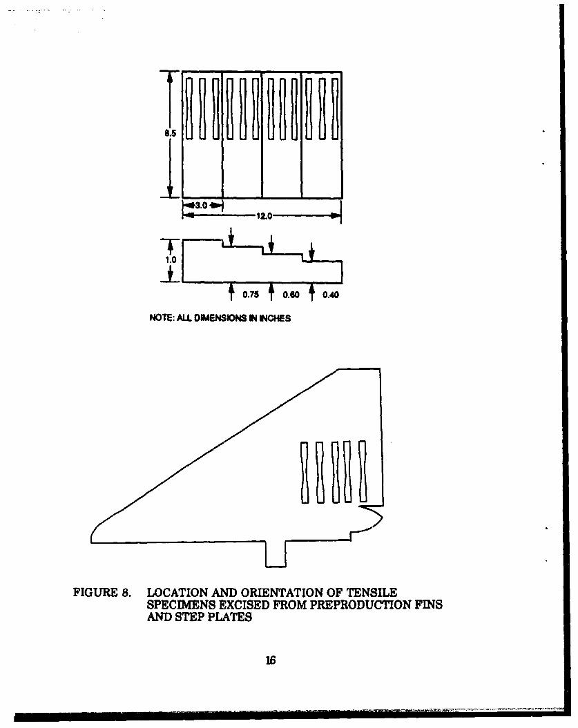
Twelve specimens were excised from each step plate and 9 specimensfrom the 2 preproduction fins for a total of 33 test specimens. Specimenorientation with respect to part geometry is shown in Figure 8. Testing wasperformed at 750F in accordance with ASTM E8 (Reference 15), and the dataare contained in Appendix B.
Data in this section represent parts produced by Supplier 2. Partsfrom Supplier I did not meet the program requirements and were notincorporated into the base plan because these castings had been annealedfor more than 2 hours in order to lower the hydrogen content. Data fromparts procured from Supplier 2 were used in later analyses for heattreatment comparison.
When we examined the differences in strength as a function ofchemistry, we noted that there was a difference in the mechanicalproperties of the castings that was related to the chemistry of the parts(Figure 9). Step plates made to the more restrictive Chemistry "B" (Table 4)had hgher properties than those cast to the less restrictive Chemistry "A.'The differences varied from 0.5 to 3 ksi, and the trends with respect tothickness were the same. When we look at the actual chemistries of thestep plates (Table 5), we see that the chemistries of both plates were tightlycontrolled and are very similar. There are differences noted in thequantities of iron, vanadium and aluminum. Both plates met the highlyrestrictive chemical composition established using the Taguchi analysis.This indicates that there will always be some variability in properties evenwhen using a highly restrictive chemistry.
13

It - --
I -0 .t
NOTE: ALL DIMENSIONS IN INCHES*MINIMUM DIMENSIONS
FIGURE 6. CAST TI-6AL-4V STEP PLATES
14

16.5
DIA
DIA
FIGURE 7. CAST TI-6AL-4V MISSILE FINS
15
Tggg1g 11888
8.5
NOTE: ALL DIMENSIONS IN INCHES
FIGURE 8. LOCATION AND ORIENTATION OF TENSILESPECIMENS EXCISED FROM PREPRODUCTION FINSAND STEP PLATES
16

134
133
132
131 C- CMIST A
1-- CHEMISTRY 8
12B
0.0 0.2 0.4 0.6 0.o 1.0 1.2THICKNESS
FIGURE 9. RELATIONSHIP OF CHEMISTRY TO STRENGTH
TABLE 6. ACTUAL CHEMISTRIES OF PREPRODUCTION PARTS
CHEMISTRY "A" CHEMI "BELEMENT PLATEPF N P= FIN |
Al f.o,0 6.2 __ .2v 3c ' .9 42 l ' .9 4.1'
e .17 02 0.18 02
W O&dr 0.028 0.02 0.026H To.& o ,. ooo41700.17 0.16,I 0.18 all1 .N .o 0.00810.0o7 0.* O
Y001 10.001 o-.ool 1 ~o 0.001
17

The "F' ratio comparison of variances and "t" test for comparison ofmeans indicated that parts from Chemistry "A" and "B" could beconsidered part of the same population. The data from parts made usingthe 2 chemistries were combined into a single population. The strength ofthe parts varied very little with part thickness (Figure 10). Standarddeviations were less than 2 for both tensile and yield strengths. These datawere compared with other data provided by Titech (Reference 16) or derivedfrom MDMSC IRAD studies of Ti-6AI-4V castings (Reference 17). Thiscomparison shows that the average strength obtained with the restrictivechemistry is lower than that obtained using process controls contained incurrent public specifications (Figure 11). Our data also showed far lessvariability than the other data sets.
Data from the preproduction parts were then used to calculatepreliminary "S"-basis allowables using the computational proceduredescribed in MIL-HDBK-5 (Reference 18). The preliminary allowables areFtu= 125 ksi and Fty= 120 ksi.
132-
130
Q 128 - ' AVG FTj
-- AVG FTY
1261
124, .
0.0 0.2 0.4 0.6 0.8 1.0 1.2
THICKNESS
FIGURE 10. RELATIONSHIP OF THICKNESS TO TENSILE STRENGTH
18

150
~140-
EMC130 JRR GRAM
1200 1 2 3 4
THICKNESS (INCH)
FIGURE 11. DATA GENERATED FROM PARTS CAST TO MORERESTRICTIVE CHEMISTRY AND POST-CASTINGTREATMENT SHOW LESS VARIABILITY THAN DATAGENERATED FROM PARTS CAST TO CURRENT PUBLICSPECIFICATIONS
3.2 NONDESTRUCTIVE INSPECTION
The Ti-6A1.4V alloy microstructure contains nearly all alpha phasewith 5-10% beta phase. Typical cast microstructures consist of alphaplatelets separated by thin beta lathes or ribs (Figure 5). The alphaplatelets are transformation products of the beta phase when cooled belowthe beta transus. During slow cooling the alpha platelets grow andcoarsen, and if cooling rates are sufficiently slow, adjacent platelets mayform colonies of similarly aligned platelets sharing a commoncrystallographic orientation. Larger colonies are developed by slow coolingrates through the beta transus with the upper size boundary for thesecolonies being the prior beta grain size.
19

Titanium castings typically exhibit large prior beta grains separatedby continuous grain boundary alpha. The prior beta grain size isdetermined by the time spent in the beta phase upon cooling, with longertimes giving larger grains. During slow cooling through the alpha + betaphase field grain boundary alpha forms on prior beta grain boundarieswith larger and more continuous alpha forming at slower cooling rates.
MDMSC has developed NDI techniques (Reference 19) to correlatemicrostructural features of investment cast titanium to mechanicalproperties. Incorporation of metallographic examination ofmicrostructure as a reliable NDI method for determining mechanicalproperties rather than relying solely on tensile prolongations has severaladvantages. There are many difficulties in trying to relate the propertiesof prolongations to those of actual cast parts. Prolongations do notrepresent different section sizes in the castings and undergo differentcooling rates than the actual casting. Different gating mechanisms mayalso be used for the prolongations than for the casting, resulting indifferent solidification rates and different microstructures andmechanical properties than those observed for the casting.
In this phase of the program, we utilized this technique to correlatethe surface microstructure of cast step plates and preproduction fins withtheir mechanical properties. The area of interest was polished with aMovipol-130 Electropolisher using an electrolyte solution consisting ofperchloric acid, methanol, and butylcellosolve. A replica of the electro-polished surface was made on acetate film and mounted for microscopy.Typical photomicrographs from replicas are shown in Figure 12. Wemeasured prior beta grain size, colony size, alpha platelet spacing, anctgrain boundary alpha content of the cast step plates and preproductionfins.
In all cases the microstructural features under considerationincreased in size with increasing section thickness (Figure 13). This is tobe expected since thicker sections cool more slowly resulting in a coarsermicrostructure. Differences in chemistry also resulted in small differencesin microstructural feature; however, these differences were not significant.When we examined the relationship of the mechanical properties tomicrostructural features, we could observe no obvious relationship betweenthe two (Figure 14). As we have shown in Section 3.1, the tightenedchemistry and post-casting treatments have produced parts with very smallvariances in mechanical properties. The same is true for themicrostructural features. Because of this, it is not possible to correlatestrength directly with microstructural feature in this thickness range (0.1inch - 1.0 inch). Maximum sizes for the microstructural featuresmeasured can be specified for this narrow range of mechanical properties(Table 6). This data will be incorporated into the specification for Ti-6AI-4Vcastings. However, more work is needed with sections thicker than 1 inchand with parts that do not meet the more restrictive processing todetermine whether these maxima are unique to our castings
20

u-i
FIGURE 12. TYPICAL PHOTOMICROGRAPHS OF REPLICAS TAKENFROM TI-6AL-4V CASTINGS
21

006 i L0D.4PAMOR BETA GAIN SIU MI.iN UOUNDARY ALPHA
0.05- 40064z
0.04 3,00-4
0-1 o.00 0o.600 o.750 1.000 0.1 o.4600 0.00 o.750 1.000THICKNIESS (INCH) THICKNE9S (INCH)
ALPHA COLONY ALPHA PLATELET SPACIPG0.OO7 .. ... L -S" .
0.006[
I.606
0004 r
0003 , * ,, . , . ,, I.Z•Oi,4 . , " - , - "
0 I 0 400 0.600 0.150 1.000 0,1 0400 0.600 0.750 1.000
THICKNISS (INCH) THICKNess (INCH)
FIGURE 13. VARIATION OF MICROSTRUCTURAL FEATURE WITHPART THICKNESS
22

0.06
O.O6'P OR HIA •8Z
0.04,
0.0t
0.02
0.01, NAPV4MO],
S- _ I000040 ALPHA ~PLAELET PACOIN129.200 129.600 131.000 131.800
"PTU (KiI)
FIGURE 14. SIZES OF THE MICROSTRUCTURAL FEATURES VARYLITTLE OVER THE NARROW PROPRTY RANGE SEEN INTHESE CASTINGS
TABLE 6. MICROSTRUCTURAL FEATURES - MAXIMUM LIMITS
MICROSTRUCTURAL PEATURE MAXIMUM- SIZE (INCH)PRIOR BETA GRAIN SIZE 0,057GRAIN BOUNDARY ALPHA 0400025ALPHA COLONY 01001I ALPHA PLATELET SPACING 0I 0057
23

SECTION 4
ESTABLISHMENT OF SPECIFICATION
Public -sp-cications are ncessary to provide unrs with reliable datafor specified, prodt fhnus. Ao en ein eed reliableinformation to datil minimum weight aifr e sircures, opte nmaterials slecion r their products, and to infrm uppliers of thepreferred practices needed to deliver perts with consistent properties.Thee acm itly 3 public specifications that are used for procurementof t/taniumn castg AMS 4938, AMS 4991, and MIL-T41916 (References20.22). AMS 4985 and AMS 4991 cover TI-4A-4V castingsand tensile properties for separately cast specimens, prolongations, orspecimens from castings. MIL-T-81915 covers cast TI-6A1-4V as well ascommercially pure titanium, Ti-5AI-2.58n, and TIN-AI-28n4Zr-2Mo andcontains properties for tensile specimens cut from castings. There is somevariability in the minimum properties that are specified in each of thesedocuments. Various radiographic grades are also specified in thedifferent specifications. In-house com specifications are often used toprocure TI-6Al-4V castings. While many hove the same chemistryrequirements as found in the public specifications, they may containprovisions not contained in the public specifications, such as theparameters for hot isostatic pressing.
Under this phase of the proposed program, we prepared a morecomprehensive and stringent opecificatson for TI-AI14V castin usinchemical limits and post-casting treatment established in our Tguchianalysis and NDI criteria. The specification was drafted in accordancewith AM8 guidelines (Reference 23). We performed both "F" ratio ofvariance analysis and "t" test for comparison of means (Reference 18) ondata sets representing both chemistries "A" and "B".
Our findings indicated that parts produced from these twochemistries did not differ significantly with respect to their averagestrengths and that the variability was not significantly different. We listedChemistry "B" in the specification since it was less restrictive thanChemistry "A". Combining data from parts using both chemistriesresulted in a population with a standard deviation of 2 ksi. The post-casting conditions called out in the specification are HIP at 16600F/15 ksl/2hours and annealing at 16506F/2 hours. Using data from step plate# andpreproduction fins, we determined the preliminary "S .basis allowables tobe Fro= 1265 hl and Fty- 120 kei. We included the NI! criteria listing themaximum coarseness for the microstructural features measured (Table 6,Section 3.2). A copy of the AMS specification is included as Appendix B.The AMS specification shown in Appendix B is a draft specification and
24

may not resemble the final copy. Features of the new specification arecompared with corresponding items in the current public specifications inTable 7.
TABLE 7. COMPARISON OF FEATURES OF SPECIFICATIONS FORCAST TI-6AL-4V
"W-MEUI l•[ET.819l5 AMIS 49 AMS1 4901 PROGRAM -SP•.WIICATION
-m~m-CHEMISRYv CURN asM AS ML.'r, S'•ASME lT. MORE RErIC1VT•5ANU3 51915 UCW? 51916 EXCZP THAN BASELINE FOR(CARBON w 005) CARBON o0.1 CARBON a 0.1 ALLM ELENTSHEAT TREAMENT PE ML-H41200 AqNNE& 1900. ANNEAL 13W- ANNEAL 15W0V
IM6*F/U HR IH6eFAW- Hit gHR
HOT IDOSlATIC IM 'A-TT No cALI.UT No CA=- T WP 0WPRFamINO 10 KOi42HRqummrr RADIOGRAPHC RAVIOGUFeC JDIOMRUHC MICRWMUTS••UPAL
P15 ANUIM 156 PER AMs 2W6 PE AM$ 2035 INsPEMON(ORADU ,M,C) (GRADE
"Ir.BA/M l'M* 8P. CAST BAWS NIA 10KBl 10 N/A* PROLONOATIONS N/A 100 Kai 130 1(i N/A- PARTS
DSBIONATSD 125(5 13181l 180 KS3 12681NONDOSIGNATED 126 K18 126 K81 127 K15 125 K81
25
SZCTION 5
"A" AND "B" ALLOWABLES
5.1 ALLOWABLES DETIEMINATION
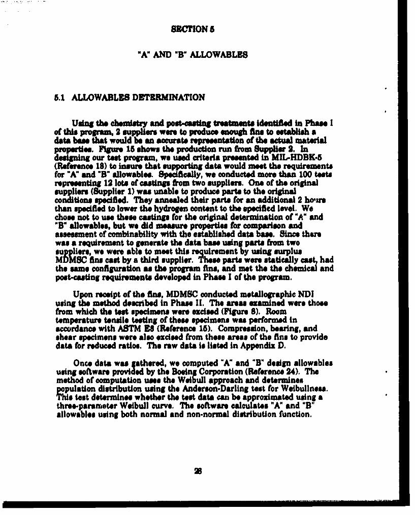
Using the chsý and treatments identfed in Phase Iof this program, 2 suppliers were to produce enough fins to estabsh adata base that would be an accurate reprentation of the actual materialprops:ties. Figure 15 shows the production run from Supplier 2. Indesigning our teat program, we used criteria presented in MIL.HDBK-5(Reference 18) to insure that supporting data would meet the requirementsfor "A" and "B" allowables. Specifically, we conducted more than 100 testsrepresenting 12 lots of costings from two suppliers. One of the originalsuppliers (Supplier 1) was unable to produce parts to the originalconditions specified. They annealed their parts for an additional 2 howuthan specified to lower the hydrogen content to the specified level. Wechose not to use these castings for the original determination of "A" and"B" allowables, but we did measure properties for comparison andassessment of combinability with the established data base. Since thmwas a requirement to generate the data base using parts from twosuppliers, we were able to meet this requirement by using surplusMDMSC fins cast by a third supplier. These parts were statically cast hadthe same configuration as the program fins, and met the the chemical andpoet-casting requirements developed in Phase I of the program.
Upon receipt of the fins, MDMSC conducted metallographic NDIusing the method described in Phase II. The areas examined were thosefrom which the test specimens were excised (Figure 8). Roomtemperature tensile testing of these specimens was performed inaccordance with ASTM ,8 (Reference 15). Compression, bearing, andshear specimens were also excised from these areas of the fins to providedata for reduced ratios. The raw data is listed in Appendix D.
Once data was gathered, we computed "A" and "B" design allowablesusing software provided by the Boeing Corporation (Reference 24). Themethod of computation uses the Weibull approach and determinespopulation distribution using the Anderson-Darling test for Weibullness.This test determines whether the test data can be approximated using athree-parameter Weibull curve. The software calculates "A" and "B"allowables using both normal and non-normal distribution function.
38

FIGURE 15. PRODUCTION FINS FROM SUPPLIER 2
We performed the 'F" ratio test for analysis of variance and "t" test foranalysis of means (Reference 18) to determine whether the fins producedby Suppliers 2 and 3 represents, the same population. The results of thesetests showed that both the variances and means were representative of thesame population and that the data could be combined. The completeresults of the data analysis are contained in Appendix D.
A summary of the allowables determination from the production finsfrom Stuppliers 2 and 3 is shown in Table 8. The analysis reveals that thedati obtained for the fins from these two suppliers fit a normaldistribution. However, the hypothesis of Weihullness was rejected for thetensile strength but not for yield strength. The "A" and "B" allowables arecompared to "S"-hasis values listed in MIL-T1-81915 and allowablesdetermined by Douglas Aircraft for the ('-17 program (Reference 25). TheC- 17 castings were supplied to AMS 4.985 in the hot isostatically pressedand annealed condition.
, ....- i....i ........ J...... .... .. .......... .. ....... . ...... . . . .

TABLE 8. "A" AND "B" ALLOWABLES
BAISSOURCE Fty (KSI[) Ftu (KSI)
NORMAL 121 126DAC 109 123
B WEIBULL 123 128NORMAL 123 128DAC 116 128
S MDMSC 1 125I MIL-T-81915 115 125
We tested 10 tensile specimens from 2 fins cast by Supplier 1. Thesefins met the chemistry requirements, but did not meet the post-castingconditions since they had been annealed for 4 hours rather than thespecified 2 hours. The mean tensile strength and yield strength are 3-6 ksilower than corresponding properties for Suppliers 2 and 3. The "F" ratioand the "t" tests showed that the fins produced by Supplier 1 could not beconsidered part of the same population as those produced by Suppliers 2and 3. The differences in the data from parts produced by Supplier I couldbe due to the additional annealing time. Coarsening of the microstructurecould bring about the lower properties in these parts. Another reason forthe difference could be that these parts were centrifugally cast rather thanstatically cast as those produced by Suppliers 2 and 3.
5.2 REDUCED RATIOS
Direct computation is the desired method for determining derivedproperties such as bearing, shear, compression, and tensile properties indirections other than the original test direction. Because obtainingsufficient data for these properties is costly, a method of indirectcomputation to determine these values is used. This method utilizespairing of individual ultimate shear or bearing values with ultimatetersile strengths. Compression and bearing yield strengths are pairedwith tensile yield strength. The basis for this computation is that themean ratio of these paired observations represents the ratio ofcorresponding population means. In the ratios, the tensile strength or thetensile ultimate strength appears in the denominator.
We determined reduced ratios for Ti-6AI-4V castings by testing threecompression, bearing and shear specimens from the fins. Thecorresponding data are shown in Table 9 and compared to thosedetermined by Douglas Aircraft (Reference 25) and by the MIL-HDBK-5
28
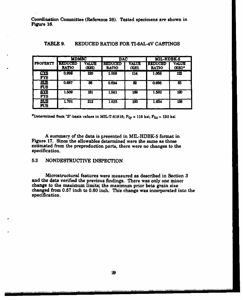
Coordination Committee (Reference 26). Tested specimens are shown in
TABLE 9. REDUCED RATIOS FOR TI-6AL-4V CASTINGS
MDMSC DAC MIL-HDBK-5PROPERTY REDUCED VALUE REDUCED VALUE REDMW VALUE
RATIO =I) RATIO (KSI) RATIO (KSD)Y 0.999 120 1.059 114 1.068
trB 0.687 86 0.694 8 0.695 83
xan 1.509 181 1.561 IN 1.562 1oPYS
L701 212 1.635 193 1.634 INIFU8
*Determined from "S"-basis values in MIL-T-81915; Fty = 115 ksi; Ftu = 120 ksi
A summary of the data is presented in MIL-HDBK-5 format inFigure 17. Since the allowables determined were the same as thoseestimated from the preproduction parts, there were no changes to the
5.3 NONDESTRUCTIVE INSPECTION
Microstructural features were measured as described in Section 3and the data verified the previous findings. There was only one minorchange to the maximum limits; the maximum prior beta grain sizechanged from 0.57 inch to 0.60 inch. This change was incorporated into the
specifcation

COMPRESSION
BEARING
SHEAR
FIGURE 16. COMPRESSION, BEARING, AND SHEAR SPECIMENSFROM TI-6AL-4V CASTINGS
30
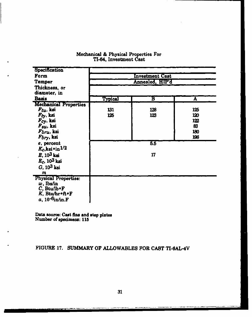
Mechanical & Physical Properties ForTI-64, Investment Cast
SpecificationForm Investment CastTemper Annealed, HE'dThickness, ordiameter, inBasis TPc B AMechanical Properties
Ftu, ksi 131 ]28 125Pty, ksi 125 123 12Dfcy, ksiFsu, ksi 83Pbru, k6i 180Fbry, kei _96
e, percent 5.5Kc,ksi .in 1/2E, 103ksi 17Ec, 103 ksiG, 1 3 ksi
Physical Properties:w, lbasmC, Btu/lb*FK, Btu/hroft.Fa, 10"6 in/in.F
Data source: Cast fins and step platesNumber of specimens: 115
FIGURE 17. SUMMARY OF ALLOWABLES FOR CAST TI-6AL-4V
31

SECTION 6
DAMAGE TOLERANCE
In Phase V, MDMSC conducted damage tolerance tests to generateplane-strain fracture toughness and constant amplitude crack growthdata per ASTM methods. All test data for the fracture mechanics work iscontained in Appendix E.
MIL-A-87221 defines durability and damage tolerance analysisrequirements for aircraft structures (Reference 27). In the damagetolerance analysis of wrought alloys, the presence of a flaw is assumed toaccount for defects that nuty arise in critical areas of parts duringmanufacturing. In castings there are inherent flaws due tomicroporosities, microshrinkaga, or contaminants. There is a lack ofdamage tolerance data that takes into consideration these casting flawsand the effects of the microstructural fractures on damage tolerance. Thislack of data prevents widespread use of castings for fatigue-critical aircraftapplications. In titanium castings, many of the flaws that occur as aresult of the casting process are "healed" by hot isostatic pressing and thusare not commonly found. The performance of titanium castings isdominated by the unique cast microstructure. The typical as-cast titaniummicrostructure consists of beta grains that grow during slow coolingthrough the beta phase field (Figure 5). Larger beta grains are associatedwith improved fatigue crack growth. Alpha phase is located along the betagrain boundaries, and alpha plate colonies are located within the betagrains. Both grain boundary alpha and the alpha colonies have beenshown to reduce fatigue life, crack initiation, and crack growth properties(Reference 28). Hot isostatic pressing will result in some coarsening of thealpha platelets leading to a lower fatigue strength but a higher fracturetoughness.
6.1 FRACTURE TOUGHNESS
In this phase we excised (per ASTM E399) 3 C(T) compact tensionspecimens for KIC determination and 3 SE(B) bend fracture toughnessspecimens (Figure 18) from the cast Ti-6AI-4V fins fabricated by Supplier2. The C(T) specimens were precracked under the conditions shown inTable 9 and tested at 75OF (Reference 29). The results of the tests are shownin Table 10. Tests were considered invalid due to the thinness of thespecimens which made the existence of plane-strain conditionsquestionable. However, the results of the testing of the compact
32

0.22 HOLES
I
BENDAC SE1-r.NON8El.
NOTE: AUl. DIMENSIONS IN INCHES. DRAWING NOT TO SAE
FIGURE 18. COMPACT TENSION SPECIMENS AND BENDn IT
SPECIMENS USED FOR FRACTURE TOUGHINESSASSESSMENT
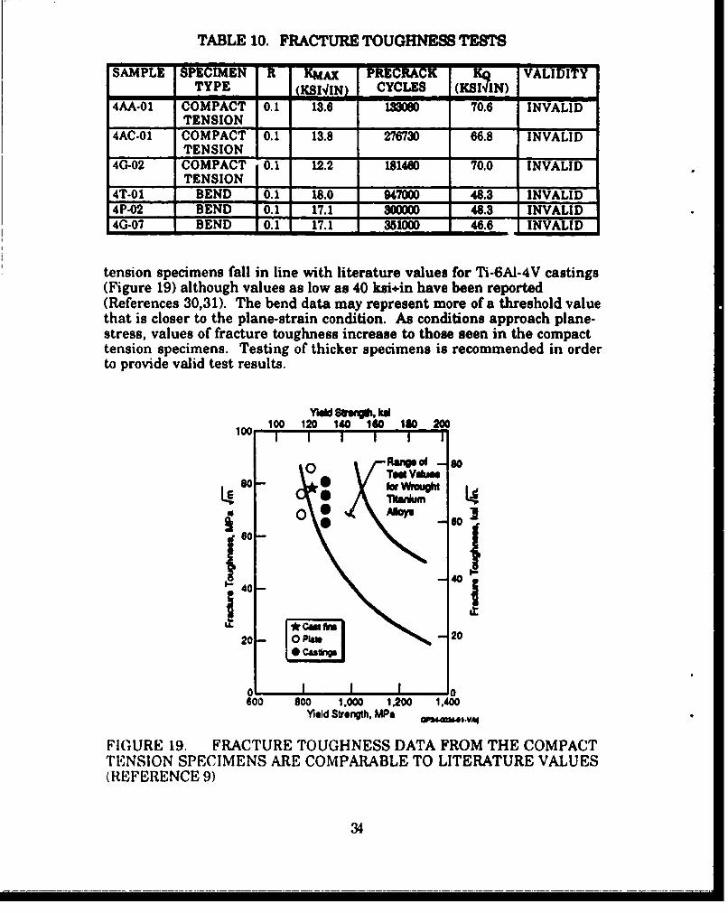
TABLE 10. FRACTURE TOUGHNESS TESTS
SAPLE SPEIMEN R KmAx PRECRACK K- VALIDITYTYPE (KSI4IN) CYCLES (KSIAIN)
-1 - m
4AA-01 COMPACT 0.1 13.6 133060 70.0 INVALIDTENSION
4AC-01 COMPACT 0.1 13.8 276730 66.8 INVALIDTENSION I
4G-02 COMPACT 01 12.2 181460 70.0 INVALIDTENSION
4T-01 BEND 10.1 18.0 947000 48.3 INVALID4P-02 BEND 10.1 17.1 300000 48.3 INVALID4G.07 BEND 10.1 17.1 351= 46.6 INVALID
tension specimens fall in line with literature values for Ti.6AI-4V castings(Figure 19) although values as low as 40 ksi+in have been reported(References 30,31). The bend data may represent more of a threshold valuethat is closer to the plane-strain condition. As conditions approach plane-stress, values of fracture toughness increase to those seen in the compacttension specimens. Testing of thicker specimens is recommended in orderto provide valid test results.
Y•dd Sft, kd100 120 140 160 160 200
0PIMPoof -soTed Values
00 0 AtsrWouh
0 1-- ,m -
so -•
I
8041 40 - C A20- IPIM - 20
o I I600 go0 1.000 12M 1.400
Yield Strength, MPe
FIGURE 19. FRACTURE TOUGHNESS DATA FROM THE COMPACTTENSION SPECIMENS ARE COMPARABLE TO LITERATURE VALUES(REFERENCE 9)
34

R-Curve measurements were also made per ASTM E561 (Reference33) for the 3 compact tension specimens listed in Table 10. The results areshown in Table 11. These measurements present the resistance to thecrack propagation (KR) as a function of crack extension beyond theinitiation phase and KIax is the maximum K level in the test. In order forthese results to be considered valid, the length of the uncracked ligamentmust be at least as great as (4/pXKma/FTY)2 which is proportional to thesize of the maximum expected plastic zone. For all 3 compact tensionspecimens tested, the length of the uncracked ligament was less than(4/pXKmax/FTY)2 . Therefore, all tests were considered invalid.
TABLE 11. R-CURVE MEASUREMENTS
"SMP• I r, KMAX UNCRACKED (4/PXKMAX/MTy)2 VALIDITY
(KI,, (KICO/IN) LIGAMENTLENGTH (IN)
4AA-01 1.7 140.9 0.3957 1.7302 INVALID4AC-01 112.7 0.4118 1.1230 INAID40 118.6 125.0 03989 113815 INVALID
6.2 FATIGUE CRACK GROWTH
Just as KIc is important in determining loads that a structuralmember can carry in the presence of a flaw, it is also important to estimatethe total operating life of components subjected to cyclic loading (i.e.,fatigue) conditions. Generally, fatigue crack propagation behavior intitanium alloys parallels that for fracture toughness. As discussed in thebeginning of this section, the cast titanium microstructure exerts a stronginfluence over fatigue behavior. Larger beta grains and alpha colonieswill increase fatigue crack propagation resistance but degrade low- andhigh-cycle fatigue strength. The presence of grain boundary alpha isdetrimental to fatigue crack initiation.
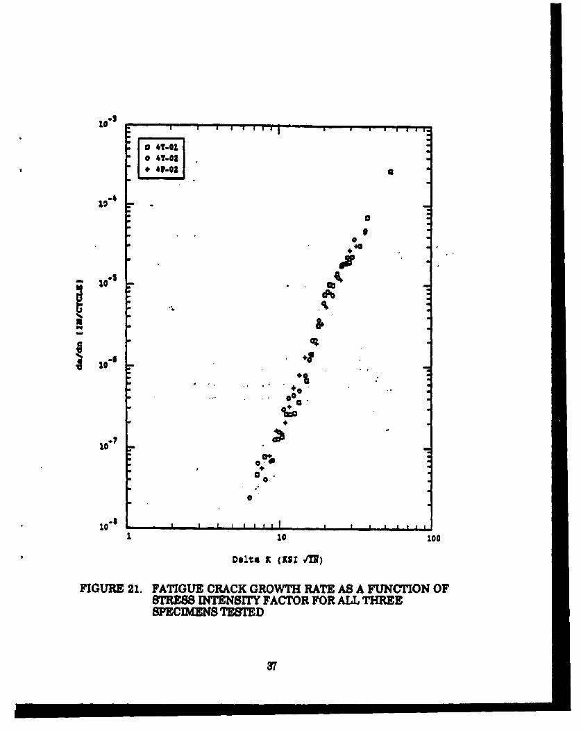
We excised 3 fatigue crack growth specimens (Figure 20) from cast Ti-6AI-4V fins and tested these compact tension specimens at 75*F inaccordance with ASTM E647 (Reference 34) using a stress ratio (i.e., theratio of minimum cyclic stress to maximum cyclic stress) of 0.1. Thefatigue specimen precracking conditions are shown in Table 12. Thefatigue crack growth rate as a function of stress intensity factor for allthree specimens is shown in Figure 21. The curves agree with literaturecurves for Ti-6A1-4V with lower oxygen content (Figure 22), and all 3 wereshown to be valid. There is minimal scatter in the data among the 3specimens, presumably a result of the tight control over the chemistry.
35

Curves showing the crack groth verus constant-mplitude sress cyclesfbr a thm pee e shown in Figure 23. Crack lengthmeaurmnts as well as other test procedures can produce variability intest results.
0252 HOLE.S
0..U
0276 - - - -
0275
1.0.
NOTE: ALL DIMENSIONS IN INCHES. DRAWING NOT TO SCALE.
FIGURE 20. FATIGUE CRACK GROWTH SPECIMEN
TABLE. 12 FATIGUE CRACK GROWTH CONDITIONS
-SAMPLE STRESS INTENSITYFACTOR RANGE
(KS IIN)4T-01 7.0904T-02 1 5.959_____P-02 _ 7.081
38
140
o 41.021
t-4
040
-10100
S10-s
Deltas x (zsI] M'])
FIGURE 21. FATIGUE CRACK GROWTH RATE AS A FUNCTION OF812t.,8 INTENSITY FACTOR FOR ALL THREESPE.CIBMSNTESTED
37
* 0m

ft is.nau Fw Rmes, aK. Kd x IK.8
10 o 40 alo 14
V,b - Iswoox Mtn
(51 kW i 6x 1/2)
"VmW d16" 6 0i13 . 0.17%
104J
10-4 Kio" 91MPS Im1 5-x 104
"~Y8 . 400 MP,& (128 klu)oxygm - 0.10%
- .• , -111 - 1 0!
10 20 40 000100
$Uieas.knlenstl P•to k a Ane MPhK x m1I
Ro 0.02:10 Wx; Air. Aigon and JP4 Envonmfet Pooled:Average of Six Teats Per Trend Une.
FIGURE 22. COMPARISON OF FATIGUE CRACK GROWTH WITHLITERATURE CITATIONS (REFERENCE 32)
38

0
00
0 0 1*XI W = 1_Y-
3Df

CONCLUSIONS AND RECOMMENDATIONS
In this program we succesfilly reduced the variability ofmechnad paropjer~os of T1-EAI-4V castings by application of a more
n!c =omposition and post-casting treatment, The use ofTagueW methods in determining these conditions provided an oliectivemeans of analyzing these paasmeters. We demonstrated that the morerestrictive chemistries and post-casting treatments could be met in aproduction hdlity by more than one supplier in the produotion of stepplates and missile fins. A data bass was developed using thes prt thatpermitted the establishment of meaningffil "A" and "B design allowablesfor investment cast TI-A1-4V. A new AMs specification was written toprovide better control of the process. This specifcation incorporated themore restrictive chemistry and post-casting treatment including hotisotatic pressing, the new allowables, and criteria for nondestructivetesting using Me asurente of microstructural features. Limited fsracturemechanics t was performed that indicated that these castings hadfracture toughness and fhtigue comparable to current cast and wrought Ti-6AI-4V. While this program accomplished the goals that it set out toachieve, there are stll isues that remain to be resolved.
One recommendation is to increase the data bae by usin the newsEpcifcation to east other part geometries and thicknesses. This wouldallow verification and/or expansion of the current data base. Since wefound that there wos a very low variability in the range of thicknesses andsection sizes investiated under this -t -am, thenr needs to be more datato determine the effects of casting thicaLer sections on the mechanicalproperties and the microstructural features. The fracture mechanics workrequires additional testing of thicker specimens to provide meaningf/ldata.
We also need to determine the actual impact of producing parte inaccordance with the now specification on the cost of the parts. Althoughthe suppliers provided inputs to guide us in selection of chemistry and post-casting treatment that would be producible, there are no actua data on thecost impacts of thes more restrictive parameters on production parts.Related to this, we need to also determine what the availability ofthismaterial would be and any cost impact due to availability issues.
Other aspects of processing need to be evaluated. Only statically castparts were available for the data base development. Centri/hzally cast partsas well as those produced using rammed graphite need to be investigated.
40

The influence of other parameters such as mold temperature, weld repair,and alternate heat treatment parameters also require additional study.
Finally, we need to apply these methods to other alloys that ar beingconsidsred for uso as castings. While these methods can be applied tocurrently available alloys, they should also be used in the development ofnew alloys.
41

8EFONS8
REFERENCES
1. MIL-M-8856 Missiles, Guided, Strength and Rigidity, GeneralSpecification for, 22 June 1959.
2. MI-A4S860 Airplane Strength and Rigidity, General Specficationfor, 22 June 1959.
3. MIL-A-21180 Aluminum-Alloy Castings, High Strength, 05November 1984.
4. Oswalt, K. J., Lii, Y.: ManufaCturing Me g& for Proems rfthropan Aluminum Casting Allowables, AFWAL-TR-84-4117, Northrop
Corporation, March 1985.
5. SAE ARP 1947 Dendrite Arm Spacing of Structural AircraftQuality 357 Aluminum Alloy Castings, Determination andAaeptance of, 01 October 1985.
6. AMS 4241 Aluminum Alloy Castings, Sand Composite, 7.OSi-0.58Mg-0.5T1-0.06Be (D357.0-T6), Solution and Precipitation HeatTreated, Aircraft Structural Quality, 01 July 1986.
7. MlL-HDBK-5 Coordination Group, Minutes of the 77th MIL-HDBK-5 Coordination Meeting, Carson City NV, 3-4 May 1989.
8. Jensen, G. A.: Effect of Chemistry on Mechanical Properties,Boeing Aerospace & Electronics, 31 October 1989.
9. Donachie, M. J.: Titanium: A Technical Guide, ASMINTERNATIONAL, Metals Park OH, 1988.
10. Yoder, G. R., Cooley, L. A., Crooker, T. W.: Fatigue Crack�pagation Resistance of Beta Annealed Ti-6Al-4V Alloys ofDiffering Interstitial Oxygen Content, Mallurgiaa rrnnaetionaA91: 1413-1420, 1978.
11. Boyer, R. R., Bajoraitis, R.: Standardization of Ti.SAI-4VProeasingu CAnditian-, AFML-TR-78-131, Boeing CommercialAirplane Company, September 1978.
12. Eylon, D.: Fatigue Crack Initiation in Hot-Isostatically Pressed Ti-6AI-4V Castings, Journal of Materialn Science 14: 1914-1920, 1979.
42

13. Eylon, D., Kerr, W. R.: The Fractographic and MetallographicMorphology of Fatigue Initiation Sites, in Fractographv in FailureAulyAij STP 645, American Society for Testing and Materials, pp.235-248, 1978.
14. Newman, J. R., Eylon, D., Thorne, J. K.: Titanium and TitaniumAlloys. Tho New Metals Handbook. Ninth Edition. Volume 15:Casting, Metals Park OH, 1988.
15. ASTM E8 Standard Test Methods for Tension Testing of MetallicMaterials. ASTM, Philadelphia PA, 1985.
16. Williams, R.: Titech International, Inc., PersonalCommunication, July 1989.
17. MDAC-MDE Independent Research and Development Project 2-150, Structures and Materials Technology, McDonneJl DouglasReport Q0931-2, Volume 1, 27 February 1989.
18. Military Handbook: Metallic Materials and Elements forAeroapace Vehicle StruCtures, MIL-HDBK-5F, 01 December 1991.
19. Hall, M. E.: Non-Destructive Insruection (NDI) of TitaniumCaaLgf, Missile Airframe Technology, McDonnell DouglasMissile Systems Company Tech Note MTN-89-34, 5 April 1990.
20. AMS 4985 Titanium Alloy Castings, Investment or RammedGraphite, 6AI-4V, Annealed, 15 July 1980.
21. AMS 4991 Titanium Alloy Castings, Investment, 6AI-4V,Annealed, 15 July 1980.
22. MIL-T-81915 Titanium and Titanium-Alloy Castings, Investment,16 March 1973.
23. Shopp, W. A., Boshoven, F., Carter, R. V., Cook, A. G., Paulovich,R. W., Poole, G. E.: Manual on The Prenaration of AerospaceMaterial Specifications (AMS), SAE, Warrendale PA, 1988.
24. Schimmels, M.: Memo STRU-BY92B-M89-386, BoeingCorporation, 06 December 1989.
25. Amin, A. S.: C-17A Design Allowables Develonment Tests for Ti-6A1-4V Investment Castings, MDC K0800, 01 May 1991.
26. Reduced Ratios for Annealed Ti-6Al-4V Casting, Item 88-19,Minutes of the 76th MIL.HDBK-5 Coordination Meeting, OrlandoFL, October 1988.
43

27. MHL-A-87221 Aircraft Structures, General Specification for, 28February 1985.
28. Eylon, D., Froes, F. H., Gardiner, R. W.: Developments inTitanium Casting Technology, JoaurALgfMa& Mj: 35-47, 1983.
29. ASTM E399 Standard Test Method for Plane-Strain FractureToughness of Metallic Materials, ASTM, Philadelphia PA, 1983.
30. Greenfield, M. A., Pierce, C. Mi., Hall, J. A.: The Effect ofMicrostructure on the Control of Mechanical Properties in Alpha-Beta Titanium Alloys in * .an am ng€:annd Tchnolow.Volume 3, Plenum Press, 1973.
31. Williams, J. C., Chestnutt, J. C., Thompson, A. W.: The Effects ofMicrostructure on Ductility and Fracture Toughness of a + PTitanium Alloys in Microstructure Fracture Toughness andFatigue Crack Growth Rate in Titanium Alloyn, Chakrabarti, A.K and Chesnutt, J. C. (ed.), TMS, Warrendale PA, 19487.
32. Campbell, J. E., Gerberich, W. W., Underwood, J. H. (eds):Agpicatian of Fracture Mchanics, American Society for Metals,Metals Park OH, 1982.
33. ASTM E561 Standard Practice for R-Curve Determination, ASTM,Philadelphia PA, 1986.
34. ASTM E647 Standard Test Method for Measurement of FatigueCrack Growth Rate, ASTM, Philadelphia PA, 1988.
44

APPENDIX A
CONTROL OF VARIABILITYTAGUCHI ANALYSIS
46

APPENDIX A
CONTROL OF VARIABILITYTAGUCHI ANALYSIS
This appendix contains the rationale and methodology used inapplication of Taguchi methods in reduction of variability in Ti-6Al-4Vcastings. The problem to be solved was the tightening of chemistry andpost-casting treatment to produce parts with minimal variability inmechanical properties. The information presented in this sectionpresumes some knowledge of the design of experiments and will notinclude a discussion of the basics of Taguchi techniques. A bibliography islisted at the end of this section for the benefit of the reader.
A.1 CHEMICAL VARIABILITY
A data set, provided by the Boeing Corporation (Reference 8), was thebasis of the analysis of the effect of composition on the variability ofmechanical properties in Ti-6A1-4V castings. This data set consisted of 943data points representing 43 heats of material. A summary of the data wasshown in Figure Al. We confined our analysis to the use of L8 matrices tosimplify our analysis. Oxygen, nitrogen, and hydrogen were analyzed inone matrix, and carbon, iron, and aluminum or vanadium in another.
The first step in our analysis was defining two levels of compositionfor each element. This was accomplished by plotting the cumulativefrequency as a function of concentration for each element and looking fornatural breaks in the data to define a "high" and "low" level for eachelement. With hydrogen, iron, and carbon, the levels were easily identified.With nitrogen and oxygen, there were no natural breaks in the frequencydistributions, and we assigned levels where 50% of the population fell oneither side of the dividing value. We found from our frequency plots thatboth vanadium and aluminum were fairly tightly controlled. Suppliers hadindicated to us that vanadium is very rigidly controlled because of its highcost.
Once the levels were defined, L8 orthogonal arrays were designed.The matrices and preliminary data are shown for both the tensile strength(Figures A2 and AS) and yield strength (Figures A4 and AS). The Taguchiloss function used was "nominal is best" since we were trying to produceparts with strengths as close to a nominal value as possible. In theanalysis, we used a Taguchi metric known as the signal-to-noise (S/N)ratio. The S/N ratio relates the magnitude of the response data (signal) to
46

A I
000
*• II fli!I!IIIII II!!!I IIIIIIIIIiiIIIIII C
.2 20 =-a 960 t z
49
47

N ft
S' I ' I
---------- .... Lto ,. ,
- .-- - --- -- -- - -- --. - -d -- .-- o---#-- - ---
A o ! l
|m , i , s l,. ;' t ,J
"0112MI..x
N3o0 iIN---------------- - -- - .. • . .. --........
N350NII .Ifl -' ,NI t
-- - - - - - -- - - - - -&I -.. ..-.. 0 . . ......'I- , . , 6 ,I • . , . 1 1 , K , - I
*2O~.N Nn to is4
- jn j K4' o
,, i*t_ ! . ! . l . ,S *O I S
I. I I I ~- : i- II .: _
U A I! l
*li J~l , , , ,
J.2.O l ! U ! I ! :
e I 5 S S S
*~ll X _ I . , , , S S _S I i I U 6 ~ 5 Aql
*31 i I * : o *
g l~tm~lV i I l I / 48

* I 0
Ifi, Uft
xl~p re, : in . :•* J€ ia~ -- S , I o S, N • I
-... I.... .I. .,N U I - O a O I
........ a...... A... . ... I * .II ,
N ....I ! ! • o ' o '
| x a P ; m o , i* I s I I Is* a o a I o a * o a
wU -- o ow x oI I I I I• N
0~l" I D e I e e nq I a ] a 1 a m, "
i4 -.-.0... A..... I -.. • e ... .. •.... . . ..... .... .. _I
V t Id~l• ItI 01 1 I I
* • H I I I II I I I I I IAI • I I N • a I I I I• I II 0• I l II IO I I
I I I I I I
SI I I I I I
NOZ * i I o ai I I I i I
* I S I a a a II o I I 8 I l
NOI-IWV31NZ ": I *
i, ' 'r"I N - I o , , - N s
wn~ezwn-iw t'
al•M? 4 a a a S I a
NO ! I
- - - - I I . 8
-..... .... . a...... ...... , ... *... ....... ---- - --
NOVI
I1 % 0 I 0 3 g I * 0 I o
* • •Im a I O I I O I
e * a i i n a a.......... i.*..... ..... ...... .& ..... .. I ... ------ ..... . .I .Ia~lII I l lI l I l I o I•I I~ I I I I I I I I I I I I I I IA lI• # I I I S S I OI
'NOl N I N m V e l ' -* a I 4
NOMW • I I I I • I I
." .. - -. . .. .- -.-- -
° I

nI
-- -- -- -------- -- -- tq•D •-- m m -, g
....... .......Sol.. i*cr u
J $ I I E I I
,N35eaA e !
I I •-u I : I " :u EU:' I ' "- I a Em-
*f I l I ' S m 's ra am
-,• o• a N - * *aIiN
hl - ** : V I I V I i a
...................... .... ....... ..............
IHI5OI~aAH Ae. .. . no.. .. a . a . a . a .
-------------------------- A-~
----- ---- ---- ---- --- a .. . J.----- --- -, . . . .. - - -. . .
I a
in• in Ir ir fu Iu PJ 4v
N300 O b, , , , , N
I I I I I I I
N31NO • (a a
O o -a a * a a a o
...... ..... ...... ..... ......l~ * .. .. I .... i ------lll I * I . l l l il l -- -- I I ..... I .. ..
a au a aNaa a a
x a a a a a0
N ' ll l l i il ~ ii l .- EU. EUlk ai i al 4ivi a~l -l al - ai EU Ji- : a a a a a a
a a a a a a
. - i . I - A - A . 6.I .. I *. I •
JOI .N3.LN? • a a a a a
9a a.N2O UJ - ' EU ' E • ,i * - a ,am A
a!
N2~O~LZN U: : : a0

................ an ----- W a -04 I I AD
I IS
. . . . . . . . . .- ---- --- --- o --- ..o. ..aa.M _4 a a * aa* S . a m " a Y , " N .S _M . I I : a I a a
• a a i a a a a
N a * a o I * o4 a * n
•-- -- - - - - - - - - - -- -- - --- O--'--- W -- - ... .. .. .....
I . I N N -I
w e wn-m x" I i
Sa a
----------------
-
---- ---- ----
----
a -In iu I c p -.d• d I * Irn l c hl,_ a . . a a. a" .. aZ *a•' *- *
--*-- --- ---
,~i Axy I i l
NO Vo V
I o
NOIbVý. IV.
*O NF( 4I r. Cu
aI a la
-N1(• ,, • ' o * * N * * r N
a a a a S a S I
a I I I a a a a
NO~3NO Ra a a a a
NOI i a a* a a a I a a a
--------- 4---------------4----------- , ,.
S * i * a a a a
a
OI.L~3±N ~.: a a a a a aIi •[ mlI i i I l •0
NO6~~ : a a

the magnitude of the standard deviation of the response data (noise). For anominal is best characteristic, the signal-to-noise ratio is definedgenerically as:
S/N = 10 Loglo ((True Average)2/(True Standard Deviation)2 ).
The resulting main effects from the analyses are shown in FiguresA6 and A7 for the tensile strength and Figures A8 and A9 for yieldstrength. These graphs show that both oxygen and nitrogen have thestrongest influence on the tensile and yield strengths within the range ofvalues identified for this data set. All of the other elements had showedlittle effect on the strength of the castings in the ranges defined. Thesignal-to-noise ratios for all except carbon decreased with increasingconcentration.
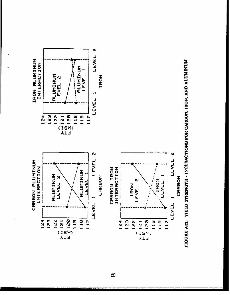
The interactions are shown in Figures A10-A12. The interactionsshown agree with known effects of the different alloying elements. Forinstance, if there are 2 elements that are both alpha stabilizers, nointeraction is shown (i.e., the interaction lines do not intersect). If theelements being compared have opposite effects (e.g., oxygen = alphastabilizer and hydrogen = beta stabilizer), an interaction is indicated withintersecting lines. The point of intersection defines the levels where theintersection is strongest.
The results of the analysis of variance revealed the contribution ofeach element to the variability of the mechanical property in question. Thisis shown in Table Al. Since only 60% of the variability can be accounted forby the chemical composition, other factors such as processing and post-casting treatment are responsible for the other 40%.
TABLE Al CONTRIBUTION OF ALLOYING ELEMENTS TOMECHANICAL PROPERTY VARIABILITY
C01RT'RIBTQION TO VARIABILITY OF:
ELEMENT FTY FTUAl 1.57% 1.62%
__ C 0.97% 6.79%H 15.08% 21.76%Fe 19.87% 17.84%
N 7.65% 4.43%15.25% 9.04%
TOTAL 60.39% 61.48%
52

SIGNAL TO NOISE
z
(IS
t~iin
00
.........------------ ---ni 4 - a
* 5a

SIGNRL TO NOISE
...... ..- .......
14~
(IS()
zz
nJ.in
(ISM1)
SIGNAL TO NOISE SIGNRL TO NOISE
to•,• .. . .. ......a. .... ..117, ...... .. r(I Y% ,/C
.... .... . .----..
0 zm
0.
t 1.4
... .. ... bi. ..-- -- -- -- . . .---
Lo ~ ~ ~ ~ ~ - -- cu --) -D()L w )C
(ISX)Ss 4) C(IS)45
Ml~l 54

SIGNAL. TO NOISE
w z...... .. ....... , P.,
0 I
it
~ I in
cu (V ow - -
c - ISW')- 0
Ak.L.d 30 Wbf3A W
SIGNPL TO NOISE SIGNRL. TO NOISE
v' (, (m 6" 'g mY cu -* (
my mW mI mY mI m ' m ' C' C
... .. .....
Z------------------------w
V
01 z
C~~J CU- - -DU (
55

SIGNAL TO NOISE
-'-------u
.... ... " "":........... 0N
m mIS')
SIGNAL TO NOISE SIGNAL TO NOISE
III
m( wnvmJ CD N W -v - Ip
S............. N " .. ............ "1CD
r N
... .... Aj.-.. 4 -------------
II1056,

z
z z .------ - LLi
0 z >
Z iCC,:'C.' ~)~ o !
o, w .a:\
(Z~l,,I,0 w
z >~Li Li
.. z ,, t, -.---,-• , i,
wP >. " \ >.00 00 w i
1hJ Q LA. z L
u-,-- z- w rn- u
'4 N ( I II 4,
HU MCu >-L w( z0
0 W ix
(9 zZw>0 L w
0 0
I SM) (ISM)
57

- ---- -----------
r r
~U N 0i
cc- (x 14-
z ~ ~ LI cr
------------ w(IS>4>
m VNN
z z~ ~ I -. z z
0 ~ Z
, --- -- -- -- --
> >4r F X 1\ cuz ~ " 2i 4s
M J,
..... - ----- ----- --- ....
-
712i.i.
58
------------ I~ .
zo Li IS0' w0
j
r 0
-i, Cc z> a:-- I > C \
c-ii \ iJ 0
J i
.4M I M "4 " - -2 M N I •J¢ - ,,,
(IS>1>
2
0
r I,
.... --------- . ------- IZ Z > z' z1-40 1: w 0
i-il ", n - XHjZ0
0'CEc 1- : 4 Z %,LhJ
zL) > >> ui -0 car Li -Im Z cc (I z.
aLai
v ~ Li Nt w L 0 MN v
AiN N N -. N No
-~~~ - - - - - - -
A.2 POST-CASTING TREATMENT
In order to determine the effects of post-casting treatment (i.e., hotisostatic pressing and annealing) on the variability of mechanicalproperties of Ti-6AI-4V castings, we used the data set shown in Figure A13.This data was a compilation of data provided to the Titanium Casting TaskGroup by various sere and suppliers. The same techniques that wereused in the chemical analysis were employed in the analysis of this datawith the exception of using L4 arrays (Figures A14, A15) for the heattreatment analysis. The results showed that minimum variance for tensilestrength is favored by using a cold mold and annealing at 1550 0F. Theminimum variance for yield strength is favored by using a cold mold andannealing at 1300°-1350*F. We chose to optimize the process for tensilestrength.
A.3 BIBLIOGRAPHY
Phadke, M. S.: gualitv Engineering Using Robust Design, Prentice Hall,Englewood Cliffs NJ, 1989.
Ross, P. J.: Taguchi Technigues for Quality Engineering, McGraw-HillBook Company, St. Louis MO, 1988.
Taguchi, G.: Systems of Exnerimental Design, American SupplierInstitute, Dearborn MI, 1981. (Note: This is translation of the Japanese 3rdedition published in 1977.)
Taguchi Steering Committee: Introduction to Taguchi Methods, CourseNumber E821, McDonnell Douglas Missile Systems Company, St. LouisMO, 01 February 1989.
60

z %
e we en
L . . m -- r
%n -, in %-n• .in W$ %M wl in %
€'LL U. &L/ /€ L ' us us M 9
.0
-I-I 1-1 :- - : 'i -1'.1z v -n
. . .00f.. . . . . .
~-0 0e C00 wl
61

ANNEALING MOLD CODE AVERAGETEMPERATURE TEMPERATURE LETTER TENSILE S S/N
(OF) STRENGTH1 1300-1350 COLD JK 139.16 2.72 34.172 1300-1350 HOT BCL 126.98 6.33 26.053 15M0 COLD AFHIM 134.18 1.14 41.384 1550 HOT G 132.44 5.33 27.91
FIGURE A14. TENSILE STRENGTH - L4 ARRAY FOR PROCESS ANDPOST-CASTING TREATMENT
ANNEALING MOLD CODE AVERAGETEMPERATURE TEMPERATURE LETTER YIELD S S/N
(OF) STRENGTH1 1300-1350 COLD JK 127.17 0.276 53.282 1300-1350 HOT BCL 115.72 6.326 26.053 m0 COLD AFHIM 121.43 3.738 30.23
54 5 HOT G 123.08 5.136 27.59
FIGURE A15. YIELD STRENGTH - L4 ARRAY FOR PROCESS ANDPOST-CASTING TREATMENT
62

APPENDIX B
PREPRODUCTION PART ANALYSIS
63

APPENDIX B
PREPRODUCTION PART ANALYSIS
This appendix contains the results of tension tests of specimensexcised from cast Ti-6AI4V preproduction fins and step plates. Data frommeasurement of microstructural features using a nondestructivetechnique are also contained in this section.
64

MECHANICAL PROPERTY DATA
SAMFL CHEIYP THICKNES(IN F ) KS' MODULUS ELONGATION58-o B 0.40 133.4 126.1 16.8 12.758-022 B 0.40 132.6 126.1 17.1 11.658-023 B 0.40 130.8 124.6 17.1 12.158-024 B 0.60 130.2 125.0 17.0 9.958-025 1 0.60 130.1 125.1 17.2 9m58-026 B 0.60 129.8 124.0 168, 10.458027 B 0.76 129.9 125.5 16.9 9.858.028 B 0.75 130.8 125.7 16.9 7.958-029 B 0.75 130.4 124.9 16.7 9.158-0210 8 1.00 132.0 126.5 16.8 6.58-0211 B 1.00 133.5 126.2 17.0 9.658.0212 B 1.00 131.2 126.4 16.9 8.840-001 B 0.10 128.7 123.4 16.9 11.24".012 B 0.10 130.1 124.0 16.8 9.340-013 a 0.10 129.9 123.6 16.7 6.040.115 B 0.10 130.1 125.1 16.8 6.6SPAI A 0.40 131.9 125.1 17.11 12.6SPA2 A 0.40 131.61 125.4 16.7 11.3SPA3 A 0.40 130.3 124.7 16.9 11.5SPA4 A 0.60 129.2 124.3 16.6 61SPAS A 0.60 128.9 123.9 16.6 10.1SPA6 A 0.60 126.8 122.5 16.6 5.6SPA7 A 0.75 129.4 124.8 16.8 6.6SPAS A 0.75 128.2 124.1 16.7 8.1SPA9 A 0.75 128.7 124.0 17.0 8.1SPA10 A 1.00 129.4 125.1 16.6 8.0SPA11 A 1.00 130.3 126.2 16.9 8.5SPA12 A 1.00 129.5 124.6 17.0 6.34A-001 A 0.10 133.5 127.7 17.5 9.24A-012 A 0.10 134.1 129.2 17.3 8.44A-013 A 0.10 133.8 128.6 17.3 8.94A-014 A 0.10 134.1 -
4A-015 A 0.10 132.2 127.4 17.3 8.1
ADATA FTU FTY E ELONGMEAN 130.7 125.5 16.9 8.6STD DEV 2.3 1.9 0.3 2.0N 17.0 16.0 16.0 16.0
8DATAMEAN 130.8 125.3 16.9 9.8STD DEV 1.4 1.2 0.1 1.4N 16.0" 16.0 16.0 16.0
ALL DATAMEAN 130.7 125.3 18.9 9.1STD DEV 1.8 1.6 0.2 1.8N 1 33.0 32.0 32.0 32.0
65
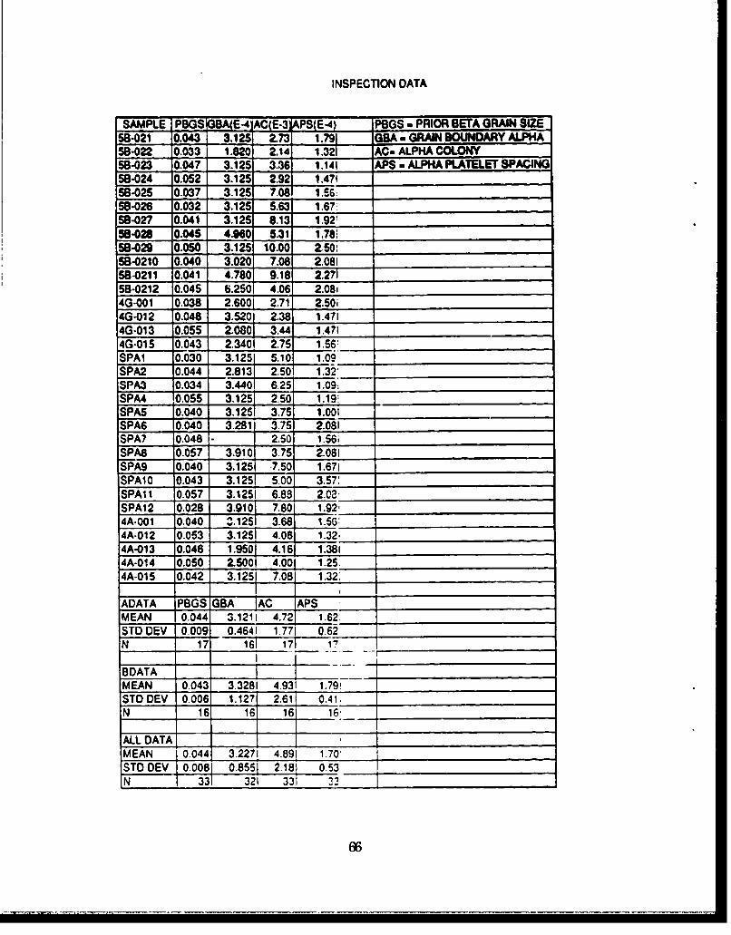
INSPECTION DATA
SAMPLE PBGS G AC(E-3 PS E-4 POGS - PRIOR BETA GRAIN SIZE58-021 0.043 3.125 2.73 1.791 GBA a GRAIN BOUNDARY ALPHA58-022 0.033 1.820 2.14 1.321 AC- ALPHA COLONY58-023 0.047 3.125 3.36 1.141 APS - ALPHA PLATELET SPACING58-024 0.052 3.125 2.92 1.47158-025 0.037 3.125 7.08 1 .%__
58-026 0.032 3.125 5.63 1.67;58-027 0.041 3.125 8.13 1.92158-028 0.045 4.960 5.31 1.78:58-029 0.050 3.125 10.00 2.50 _
58-0210 0.040 3.020 7.08 2.08158-0211 0.041 4.780 9.18 F 2.2715B-0212 0.045 6.250 4.06 2.08i4G-001 0.038 2.6001 2.71 2.50i4G-012 0.048 3.520 .38 1.4714G-013 0.055 2.080 3.44 1.4714G-015 0.043 2.340 2.75 1.56:SPAI 0.030 3.125 5.10 1.09SPA2 0.044 2.813 2.50 1.322'SPA3 0.034 3.440 6.25 1.09:SPA4 0.055 3.125 2.50 1.19:SPAS 0.040 3.1251 3.75 1.00iSPA6 0.040 3.281 3.75 2.081SPA7 0.048 2.50 1.561SPA8 0.057 3.910 3.75 2.081SPA9 0.040 3.125 -7.50 1.67iSPA10 0.043 3.125 5.00 3.57:SPAI 1 0.057 3.1251 6.88 2.02.SPA12 0.028 3.910 7.801 1.92-4A-001 0.040 2.125 3.681 1.56:4A.012 0.053 3.1251 4.06 1.32,4A-013 0.046 1.950 4.16 1.3814A-014 0.050 2.500 4.001 1.25. ,,4A-015 0.042 3.125 7.08 1.32.
ADATA PBGS GBA AC APSMEAN 0.044 3.1211 4.72 1.62 _
STD DEV 0.009 0.4641 1.771 0.62N 17 161 17"1:
BDATA -...
MEAN 0.043 3.3281 4.931 1.79,STD DEV 0.006 1.127 2.611 0.41.N 16 16 161 16,
ALL DATA _
MEAN 0.044 3.2271 4.891 1.70!
STO DEV 10.0081 0.8551 2.181 0.53N 1 331 321 331 3'
66

APPENDIX C
ORIGINAL DRAFT OFPROPOSED AMS SPECIFICATION
FORTITANIUM ALLOY CASTINGS, INVESTMENT
6AL-4V
67

APPENDIX C
ORIGINAL DRAFT OF PROPOSED AMS SPECIFICATION FORTITANIUM ALLOY CASTINGS, INVESTMENT 6AL-4V
The specification in this appendix incorporates the data has has beengenerated by this program. This includes a more restrictive chemicalcomposition, new mechanial property limits, and limits for amicrostructural nondestructive inspection technique. The specification isbeing reviewed by the MIL-HDBK-5 ad hoc Titanium Casting Task Groupand will be submitted to AMS for review.
This is a preliminary draft of the proposed AMS specification. It maynot resemble the final version.

TITANIUM ALLOY CASTINGS, INVESTMENT6A1 - 4V, Aerospace Quality
Annealed
1. SCOPE:
1.1 Form:
This specification covers an aerospace quality titanium alloy in theform of investment castings cast using static methods.
1.2 Application:
This product has been used typically for parts of intricate designrequiring a combination of good strength-to-weight ratio properties,and corrosion resistance up to 750*F (3990C), but usage is not limitedto such applications.
2. APPLICABLE DOCUMENTS:
The following publications form a part of this specification to theextent specified herein. The latest issue of SAE publications shallapply. The applicable issue of other publications shall be the issue ineffect on the date of the purchase order.
2.1 SAE Publications:
Available from SAE, 400 Commonwealth Drive, Warrendale, PA15096-0001.
AMS 2249 Chemical Check Analysis Limits, Titanium andTitanium Alloys
AMS 2360 Room Temperature Tensile Properties of CastingsAMS 2804 Identification, CastingsAMS 2750 Pyrometry
2.2 ASTM Publications:
Available from ASTM, 1916 Race Street, Philadelphia, PA. 19103-1187.
ASTM E 8 Tension Testing of Metallic MaterialsASTM E 120 Chemical Analysis of Titanium and Titanium AlloysASTM E 1320 Standard Reference Radiographs for Titanium
Castings
2.3 Government Publications:
69

Available from Standardization Documents Order Desk, Building 4D,700 Robbins Avenue, Philadelphia, PA. 19111-5094
MIL-H-81200 Heat Treatment of Titanium and Titanium AlloysMIL-STD-453 Inspection, RadiographicMIL-STD-2073-l DoD Material Procedures for Development and
Application of Packaging RequirementsMIL-STD-6866 Inspection, Liquid PenetrantMIL-ST-2175 Castings, Classification and Inspection of
3. TECHNICAL REQUIREMENTS:
3.1 Composition:
Castings shall conform to the percentages by weight shown in Table1, determined by wet chemical methods in accordance with ASTM E120, by spectrochemical methods, or by other analytical methodsacceptable to purchaser (see 8.2. 1):
Table 1 - Composition
Element min max
Aluminum 5.75 6.50Vanadium 3.60 4.50Iron -- 0.25Oxygen 0.13 0.17Carbon -- 0.07Nitrogen 0.01 0.03 (300 ppm)Hydrogen - 0.01 (100 ppm)Yttrium -- 0.005Residual elements, each (3.1.2) -- 0.10Residual elements, total (3.1.2) -- 0.40Titanium remainder
3.1.1 Vendor may also test for any elements not listed in Table 1 andinclude this analysis in the report of 4.5. Limits of acceptability maybe specified by purchaser (see 8.2.2).
3.1.2 Check Analysis: Composition variations shall meet therequirements of AMS 2249; no variation over the maximum will bepermitted for yttrium.
3.2 Melt Practice:
Castings shall be poured at vendor's facility from a master heat.
70

3.2.1 Alloy shall be multiple melted; the final melting cycle shall be undervacuum. The first melt shall be made by consumable electrode,nonconsumable electrode, electron beam, or plasma arc meltingpractice. The subsequent melt or melts shall be made usingconsumable electrode practice with no alloy additions permitted inthe last consumable electrode melt.
3.2.2 The metal for castings and specimens shall be melted and pouredunder vacuum without loss of vacuum between melting andpouring.
3.2.3 Portions of two or more qualified master heats (see 3.4.1) may bemelted together and poured into castings using a procedureauthorized by purchaser. The two or more qualified master heats,when melted together and poured, shall be requalified and shallhave a different master heat number.
3.2.4 Vendor shall have a written procedure acceptable to purchaserwhich defines the controls, tests, and traceability criteria forcastings. Control factors of 4.4.2.2 shall apply. The writtenprocedure shall be only one used for the purchaser for a designatedpart once it is established and approved. Changes to the writtenprocedure shall be made only when permitted by the purchaser.
3.3 Condition:
Hot isostatically pressed
3.4 Test Specimens:
Specimens shall be machined from castings.
3.4.1 Each master heat shall be qualified by evaluation of chemical andtensile property specimens unless otherwise specified (see 8.2.4) bypurchaser.
3.4.2 Chemical Analysis Specimens: Shall be of any convenient size andshape.
3.4.3 Tensile Specimens: Shall be of standard proportions in accordance
with ASTM publications referenced in 3.6.
3.5 Heat Treatment:
Castings and representative tensile specimens shall be hotisostatically pressed in accordance with 3.5.1, and heat treated asspecified in 3.5.2. Pyrometry shall be in accordance with AMS 2750.
71

3.5.1 Hot Isostatic Pressing: Castings and specimens shall be hotisostatically pressed at 15 ksi&0.5 kai (100 MPa ±3 MPa) at atemperature of 1650*F±250 F (899*C+140C) for 2 hours and cooled inthe autoclave to below 800OF (4270C).
3.5.2 Anneal: Heat to 1550*Ft250F (8430Cj140 C) for 2 hours in avacuum.
3.6 Properties:
Conformance shall be based upon testing of specimens machinedfrom casting.
3.6.1 Room Temperature Tensile Properties: Castings one inch and lessin thickness shall be as specified in Table 2 determined inaccordance with ASTM E 8 with the rate of strain maintained at0.003-0.007 inch/inch/minute through the yield strength and thenincreased so as to produce failure in approximately one additionalminute.
TABLE 2 - Minimum Tensile Properties, Specimens Machined from
Casting
Property Value
Tensile Strength 125 ksi (868 MPa)Yield Strength at 0.2% offset 120 ksi (834 MPa)Elongation 5.5%
3.7 Surface Contamination: Castings shall be free of any oxygen-richlayer such as alpha case, any carbon rich layer, or other surfacecontamination determined by metallographic examination at 10OXminimum magnification.
3.8 Quality: Castings, as received by purchaser, shall be uniform inquality and condition, sound and free from foreign materials andimperfections detrimental to usage of the castings.
3.8.1.1 Castings shall be free of cracks, laps, hot tears, and cold shuts.
3.8.1.2 Castings shall not be exposed to chlorinated solvents.
3.8.1.3 Castings may be exposed to organic halogen-bearing compoundsif promptly and completely removed by subsequent cleaning usingprocedures acceptable to purchaser.
72

3.8.2 Acceptance standards for radiographic, fluorescent penetrant,visual, and other inspection methods shall be as agreed upon bypurchaser and vendor.
3.8.2.1 Unless otherwise specified, MIL-STD-2175 may be used to specifyfrequency of inspection (casting class).
3.8.2.2 Unless otherwise specified, ASTM E 1320 may be used to specifyradiographic standards (casting grade).
3.8.2.3 When acceptance standards are not specified, grade C of MIL-STD-2175 shall apply. In designated areas, Grade B is required.
3.8.3 Castings shall be produced under radiographic control. This controlshall consist of radiographic examination of each casting partnumber until foundry manufacturing controls in accordance with4.4.2 have been established. Additional radiography shall beconducted in accordance with the frequency of inspection specifiedby purchaser, or as necessary to ensure continued maintenance ofinternal quality.
3.8.3.1 Unless otherwise specified, radiographic inspection shall beconducted in accordance with MIL-STD-453 or other processmethod specified by purchaser.
3.8.4 Fluorescent penetrant inspection in accordance with MIL-STD-6866 or other process method specified by purchaser.
3.8.5 Castings shall not be peened, plugged, impregnated, or weldedunless authorized by purchaser.
3.8.5.1 Purchaser shall define critical or no weld zones.
3.8.5.2 If in-process welding of castings that have been hotisostaticolly pressed is authorized by purchaser, castings shallbe annealed in accordance with 4.6.3 after welding.
4.0 QUALITY ASSURANCE PROVISIONS:
4.1 Retsponsibility for Inspection:
The vendor of castings shall supply all samples for vendor's tests andshall be responsible for performing all required tests. Purchaserreserves the right to sample and perform any confirmatory testingdeemed necessary to ensure that the castings conform to therequirements of this specification.
4.2 Classification of Tests:
73

4.2.1 Except as specified in 4.2.2, tests for composition (3.1), tensileproperties (3.6.1), surface contamination (3.7), and qualityrequirements (3.8) are acceptance tests and shall be performed asspecified in 4.3.
4.2.2 Periodic Tests: Tests for radiographic soundness (3.8.3) are periodictests and shall be performed at a frequency selected by vendor unlessa frequency of testing is specified by purchaser.
4.2.3 Pre-production Tests: Tests for conformance to all technicalrequirements of this specification are pro-production tests and shallbe performed on the first-article control casting (4.8.2), when changeIn control factors (4.4.2.2) occurs, or when purchaser deemsconfirmatory testing to be required.
4.3 Sampling and Testintr
The minimum testing performed by vendor shall be in accordancewith the following:
4.3.1 One chemical analysis specimen or a casting from each master heatshall be tested for conformance with Table 1. Hydrogen, nitrogen,and oxygen deterninations shall be obtained on a lot basis after allthermal and chemical processing are completed.
4.3,2 One pre-production casting in accordance with 4.4 shall e tested tothe requirements of the casting drawing and to all technicalrequirements of this specification.
4,3,2.1 First article dimensional inspection sa:nple quantity shall be asspecified by purchaser.
4.3.3 Tensile tests shall be conducted to determine conformance with3.6. 1. Sampling and test frequency is dependent upon the type andorigin of specimens specifled by purchaser,
4.3.1. I At leant one casting of the lowest radiographic quality shall be"selectod from each loot (see 8.2.6) and tested after hot isostaticpressing and annealing at each location shown on theengineering drawing for conformance with 3,6.1.
4.3.3.1.1 When size and location of specimens arc not shown at leastthree tent specimens shall be tented, including one Irom thethickest section and one from the thinnest suction. Onesestablished under 4,4,2.2, test locations may be changed only a&agreed upon by purchnoer and vendor,
74

4.3.3.2 When casting size, section thickness, gating method, or otherfactors do not permit conformance to 4.3.3.1, sampling and testingshall be as agreed upon by purchaser and vendor.
4.3.4 Castings shall be inspected in accordance with 3.8.2.1 to themethods, frequency, and acceptance standards specified bypurchaser and vendor.
4.4 Approval:
4.4.1 Sample casting(s) from new or reworked master patterns producedunder the casting procedure of 4.4.2 shall be approved by purchaserbefore castings for production use are supplied.
4.4.2 For each casting part number, vendor shall establish parameters forprocess control factors that will consistently produce castings andtest specimens meeting the requirements of the casting drawing andthis specification. These parameters shall constitute the approvedcasting procedure and shall be used for the production of subeequentcastings. If it is necessary to make any change to these parameters,vendor shall submit a statement of the proposed change forpurchaser re-approval. When requested, vendor shall also submittest specimens, sample castings, etc. to purchaser for re-approval.
4.4.2.1 Production castings produced prior to receipt of purchaser'sapproval shall be at the vendor's risk.
4.4.2.2 Control factors for producing castings include, but are not limitedto, the factors of Table 3. Supplier's procedures shall identifytolerances, ranges, and/or control limits.
TABLE 3 - Control Factors
a. Composition of ceramic cores, if usedb. Arrangement and number of patterns used in the moldc. Size, shape, and location of gatas and risersd. Mold refractory formulationa. Grain refinement methodsf. Mold back-up material (weight, thickness, or number of dips)
Type of furnace, and charge for meltingIt Mold preheat and metal pouring temperatures
i Solidification and cooling procedures.. • "leaning operations (mechanical and chemical)k H,*t treatmentI Hot isostatic pressingm rWghtening11, i hatal Inspec lion methodso. location of specimens machined from casting--------------------------------------------------
78

4.4.2.2.1 Any of the control factors of Table 3 for which parameters areconsidered proprietary by vendor may be assigned a codedesignation. Each variation in such parameters shall beassigned a modified code designation.
4.4.2.2.1.1 Purchaser shall be entitled to review proprietary control factordetails and coding at vendor's facility.
4.5 Reports:
The vendor of castings shall furnish with each shipment a reportshowing the results of acceptance tests to determine conformance tothe technical requirements of this specification. This report shallinclude the purchase order number, master heat identification, heattreat/HIP/lot identification, AMS.49XXY, part number, quantity, andsource of property specimens (see 4.3.3.1.1).
4.6 Resampling and Retesting:
If the results of a valid test fail to meet the requirements, twoadditional specimens in accordance with 4.3 from the same masterheat or lot, as applicable, shall be tested for each nonconformingcharacteristic. The results of each additional test, and the average ofthe results of all tests (original and retests) shall meet the specifiedrequirements; otherwise, the master heat or lot shall be rejected.Results of all tests shall be reported, including data that does notmeet the specified requirements,
4.6.1 A test may be declared invalid if failure is duo to specimenmispreparation, test equipment malfunction, or improper testprocedure.
4.6.2 In addition to 4.6.1, a tensile may be declared invalid if failure is due
to random process defects such as inclusions or gas holes.
5. PREPARATION FOR DELIVERY:
6.1 Identification:
Individual castings shall be identified in accordance with AMS 2804.
5. 1.1 Traceability: Individual castings shall be traceable to theirconditions of manufacture and inspection up to and including thepoint or acceptance by tho purchaer,
6.2 Packaging:
76

Castings shall be prepared for shipment in accordance withcommercial practice and in compliance with applicable rules andregulations pertaining to the handling, packaging, andtransportation of the castings to ensure carrier acceptance and safedelivery.
5.2.1 For direct U.S. Military procurement, packaging shall be inaccordance with MIL-STD-2073-1, Commercial level, unless Level Ais specified in the request for procurement.
6. ACKNOWLEDGEMENT:
A vendor shall mention this specification number and its revisionletter in all quotations and when acknowledging purchase orders.
7. REJECTIONS:
Castings not conforming to this specification, or to modificationsauthorized by purchaser, will be subject to rejection.
8. NOTES:
8.1 Marginal Indicia:
New issue. Not used.
8.2 Definitions:
8.2.1 "Acceptable to purchaser": Does not require prior written approvalfrom purchaser, but allows vendor to make a decision andpurchaser the right to disapprove the decision.
8.2,2 "Purchaser": The cognizant ongineering organization responsiblefor casting design and fitness for use, or the designee of thisengineering organization.
8.2.3 "Authorized by purchaser"; Requires prior written approval fromthe purchaser.
8.2.4 "Specified": Requires documented instruction from purchaserthrough casting drawing, purchase order, specification, or otherengineering documentation,
8,2.6 "Agreed upon by purchaser and ve:,Jor": Requires concurrence orboth purchaser and vendor. Such concurrence is typicallydocumented by way of the casting drawing, purchase order, or otheranginooring documentation,
77

8.2.6 "Lot": For hydrogen testing, and for room temperature tensiletesting, a lot shall consist of all castings of the same part number,poured from a single master heat in one or more consecutive melts(see 8.2.7) through a single furnace campaign of not longer thantwelve hours and processed through each hot isostatic pressing andanneal in the same furnace loads. For visual and nondestructivetesting, a lot shall consist of castings of the same part number,manufactured under the same process control parameters of 4.4.2.2.
8.2.7 "Melt": All castings poured from a single furnace charge. Alsoreferred to as remelt, submelt, heat, or subheat.
8.3 Dimensions and properties in inch/pound units and the Fahrenheittemperatures are primary; dimensions and properties in SI units,and the Celsius temperatures are shown as the approximateequivalents of the primary units and are presented only forinformation.
8.4 Purchase documents, including those for direct U.S. Militaryprocurement, should specify not less than the following:
Title, number, and date of this specificationPart number or pattern number of castings desiredQuantity of castings desiredSize and location of specimens for room temperature, elevated
temperature tensile and creep rupture testing are specified (see3.4.4.2 and 3.6)
Inspection methods and acceptance standards (see 3.8.2)Level A packaging, if required (see 5.2.1)
Key words: Aerospace Quality, Castings, Investment Castings, PrecisionCastings, Titanium Alloy, Ti.6AI.4V.
PREPARED UNDER THE JURISDICTION OF AMS COMMITTEE G.
7h

APPENDIX D
CAST TI-6AL.4V PRODUCTION FIN ANALYSISMECHANICAL PROPERTY DATAMICROSTRUCTURAL NDI DATA
"A" AND "B" ALLOWABLE ANALYSIS
7,

APPENDIX D
CAST TI-6AL-4V PRODUCTION FIN ANALYSIS
This appendix contains the following data discussed previously inSection 5 of this report:
D.1 Tabulated data for the cast Ti-6A1-4V production finsD.2 Allowables generated using the Boeing software programD.3 Typical stress-strain curvesD.4 Compression, bearing, and shear data
M

D.1 MECHANICAL PROPERTY AND MICROSTRUCTURAL DATAFOR CAST TI-6AL-4V FINS

A(1>- MiI
gig
Jil ,9-1 sl-h . A 14; r-t : e s 11 iLU 60m jC49 NI llww w iC1
I 35siMs
I I 1,Ph~i~~I
NI I RI 11111 1;'"1Ij 1ij

Us a V- W.p- T
S~I ILv w m •i 1114wwC i l -1 ' iw l' i.
t-~~~~ ~ ~ ~ - -,ta nq& V' AC ~ l pqq Q
fo rm" "
VU..9
q
q --W. - -- - - - --
~~itiiimw almIi I I iiUlli£3 •
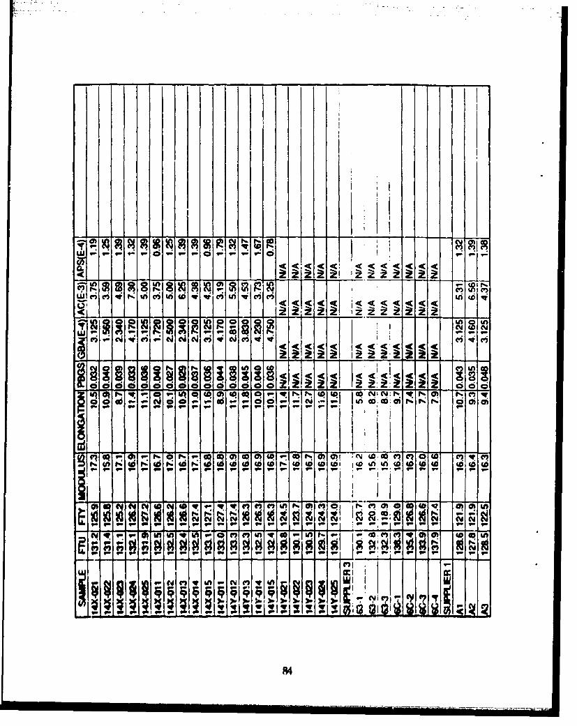
to 1- 9 -_
ci~~~k~ _____i - :w iC1ri4 mvw 4C
9. q. q- . 1- p ., .p .1 . '
9" _ggig g Ig 11111
___ _ __84

4'I1
ci~to OIQ1 -
Z .r w N I
0 5 civ
2U
£yc - -

D.2 "A" AND "B" ALLOWABLES GENERATED USING BOEINGSOFTWARE
86

ALL FTU DATASUPPLIERS 1, 2, AND 3
Sample Size a 125 Error Return Code IER = 0
ALLOWABLES3p-Weibull Allowables
A a 125.112 B = 127.834
Normal AllowablesA = 125.593 B = 127.965
Nonparansetric AllowablesA a ******** B = 127.800
Weibull Parameter Estimates (3p-Weibull)Threshold a 125.595 Scale = 6.144 Shape = 2.832
Normal estimates of 1- and 10-percentilesx(.01) x 126.247 x(.10) = 128.413
3p-Weibull estimates of 1- and 10-percentilesx(.01) = 126.806 x(.10) = 128.371
Other Sample StatisticsMean a 131.070 Stand. Deviation = 2.073Skewness a .481 Kurtosis = .782
Coeff. of Variation £ .016
Test for NormalityAD z .627 P-value = .105518 IEX = 0
A P-value less than .05 is significant evidence againstthe hypothesis of normality according to MIL-HDBK 5
Test for the 3p-Weibull DistributionAD a .637 P-value = .093499 IEX 0
A P-value less than .05 is significant evidence againstthe hypothtsis of 3p-Weibullness according to MIL-HDBK 5
The 13 smallest data values are126.800 127.400 127.500 127.700 127.800 127.800 127.800 127.800127.800 128.100 128.100 128.100 128.200
The 13 largest data values are133.300 133.400 133.500 133.500 133.800 133.900 134.100 134.100134.600 135.400 135.800 137.900 138.300
87

FTU
SUPPLIERS 2 AND 3
Sample Size = 115 Error Return Code IR 0
ALLOWABLES3p-Weibull Allowables
A a 124.970 B a 128.113
Normal AllowablesA = 126.175 8 * 128.406
Nonparametric AllowablesA a ******* B a 128.200
Weibull Parameter Estimates (3p-Weibull)Threshold a 125.686 Scale a 6.305 Shape - 3.075
Normal estimates of 1- and 10-percentilesx(.01) = 126.817 x(.10) a 128.846
3p-Weibull estimates of 1- and 10-percentilesx(.01) = 127.098 x(.10) a 128.719
Other Sample StatisticsMean a 131.335 Stand. Deviation w 1.942Skewness 2 .590 Kurtosis a 1.297
Coeff. of Variation = .015
Test for NormalityAD a .668 P-value a .083832 IEX a 0
A P-value less than .05 is significant evidence againstthe hypothesis of normality according to MIL-HDBK S
Test for the 3p-Weibull DistributionAD z .828 P-value a .030332 IEX a 0
A P-value less than .05 is significant evidence againstthe hypothesis of 3p-Weibullness according to MIL-HDBK 5
The 12 smallest data values are126.800 127.800 127.800 128.100 128.100 128.200 128.600 128.700128.700 128.900 128.900 129.100
The 12 largest data values are133.400 133.500 133.500 133.800 133.900 134.100 134.100 134.600135.400 135.800 137.900 138.300
88

SUPPLIER 2
Sample Size 1 108 Error Return Code ZER • 0
ALLOWABLES3p-Weibull Allowables
A = 126.190 8 a 128.522
Normal AllowablesA a 126.621 B a 128.570
Nonparametric AllowablesA a ******** B z 128.200
Weibull Parameter Estimates (3p-Weibull)Threshold w 126.075 Scale a 5.639 Shape • 3.346
Normal estimates of 1- and 10-percentilesx(.01) a 127.201 x(.10) a 128.968
3p-Weibull estimates of 1- and 10-percentilesx(.01) a 127.501 x(.10) a 128.953
Other Sample StatisticsMean a 131.137 Stand. Deviation a 1.692Skewness a -. 065 Kurtosis a -. 386
Coeff. of Variation a .013
Test for NormalityAD a .570 P-value a .139710 IEX a 0
A P-value less than .05 is significant evidence againstthe hypothesis of normality according to MIL-HDBK 5
Test for the 3p-Weibull DistributionAD a .513 P-value = .192532 IEX a 0
A P-value less than .0S is significant evidence againstthe hypothesis of 3p-Weibullness according to MIL-HDBK 5
The 12 smallest data values are126.800 127.800 127.800 128.100 128.100 128.200 128.600 12A.700128.700 120.900 128.900 129.100
The 12 largest data values are133.100 133.200 133.300 133.300 133.400 133.500 133.500 133.800134.100 134.100 134.600 135.800
89
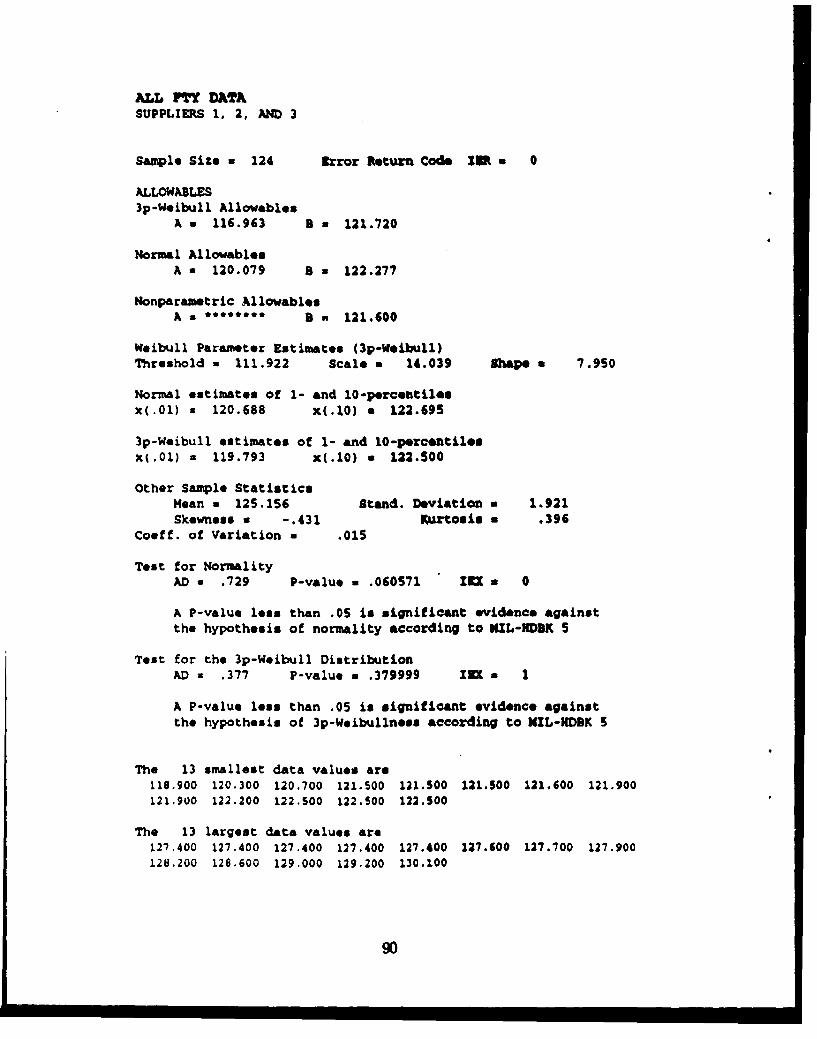
ALL FTY DATASUPPLIERS 1. 2, AND 3
Sample Size a 124 Error Return Code 25 * 0
ALLOWABLES3p-Weibull Allowables
A = 116.963 8 a 121.720
Normal AllowablesA w 120.079 8 a 122.277
Monparametric Al lowablesA ***a**** 3 a 121.600
Weibull Parameter Estimates (3p-Weibull)Threshold a 111.922 Scale a 14.039 IhApe a 7.950
Normal estimates of 1- and 10-percentilesx(.01) x 120.688 x(.10) a 122.695
3p-Weibull estimates of 1- and 10-percentilesxt.01) a 119.793 x(.10) a 122.500
Other Sample StatisticsMean a 125.156 Stand. Deviation a 1.921Skewness a -. 431 Kurtosis a .396
Coeff. of Variation a .O1S
Test for NormalityAD a .729 P-value a .060571 In a 0
A P-value less than .0S is significant evidence againstthe hypothesis of normality according to NIIL-HDSK 5
Test for the 3p-Weibull DistributionAD a .377 P-value a .379999 ZEX 1
A P-value less than .05 is significant evidence againstthe hypothesis of 3p-Weibullness according to NIL-iDBK S
The 13 smallest data values are118.900 120.300 120.700 121.500 121.S00 121.500 121.600 121.900121.900 122.200 122.S00 122.S00 122.300
The 13 largest data values are127.400 127.400 127.400 127.400 127.400 127.600 127.700 127.900128.200 128.600 129.000 129.200 130.100
90

SUPPLIE•S 2 AMD 3
*SaMPlo Size a 114 rzror Return Code 3R a 0
3p-Weibull AllowablesA a 119.932 3 a 122.662
Normal AllowablesA a 120.925 3 a 122.880
Monparametric AllowablesA a *****8** 9 a 122.500
Weibull Parameter Estimates (3p-Woibull)Threshold - 118.020 scale a 8.069 Shape * 4.903
Normal estimates of 1- and 10-percentilesx(.01) a 121.490 x(.10) a 123.269
3p-Weibull estimates of 1- and 10-percentilesx(.01) w 121.178 x(.10) a 123.120
Other Sample StatisticsMean - 125.452 Stand. Deviation a 1.703Skewness a -. 462 Kurtosis a 1.550
Coeff. of Variation a .014
Test for NormalityAD a .578 P-value a .135037 IZE a 0
A P-value lezs than .05 is significant evidence againstthe hypothesis of normality according to MIL-HDBK 5
Test for the 3p-Weibull DistributionAD M .658 P-value a .082438 KU - 0
A P-value less than .0S is significant evidence againstthe hypothesis of 3p-Weibullness according to NIL-I4DBK S
The 12 smallest data values are118.900 120.300 122.500 122.S00 122.500 122.500 123.000 123.200123.400 123.400 123.600 123.600
The 12 largest data values are127.400 127.400 127.400 127.400 127.600 127.700 127.900 128.200128.600 129.000 129.200 130.100
91

SUPPLIRR 2
Sample Size a 107 Error Return Code ZER a 0
3p-Weibull AlloetblesA a 12%.854 8 a 123.496
Normal AllowablesA a 121.S22 8 a 123.241
Nonparometria AllowablesA a t******* 8 a 123.200
WVibull Parameter Estimates (3p-Weibull)Threshold a 121.92S Scale a 4.023 Shape 2 3.583
Normal estimates of 1- and 10-percentilesx(.01) a 122.036 x(.10) a 123.S93
3p-Weibull estimates of 1- and 10-percentilesx(.01) a 122.603 Y(.10) a 123.608
Other Sample StatisticsMean a 125.503 Stand. Deviation a 1.490Skewness w .213 Kurtosis a -. 037
Coeff. of Variation • .012
Test for NormalityAD a .400 P-value a .310509 ZEX a 1
A P-value lse than .05 is significant evidence againstthe hypothesis of normality according to NIL-IDSK 5
Test for the 3p-Weibull DistributionAD a .468 P-value a .24651S lZX 0
A P-value less than .0S is significant evidenca againstthe hypothesis of 3p-Weibullness according to MTL-KDBK 5
The 11 smallest data values are122.500 122.S00 122.500 122.500 123.000 123.200 123.400 123.400123.600 123.-00 123.600
The 11 largest data values are127.400 127.400 127.400 127.400 127.600 127.700 127.900 121.200128.600 129.200 130.100

D.3 TYPICAL STRESS-STRAIN CURVES

111511111~~~~ orI I I I -iit--- Ilj IIIl
Is 0
ON)s3I
N9
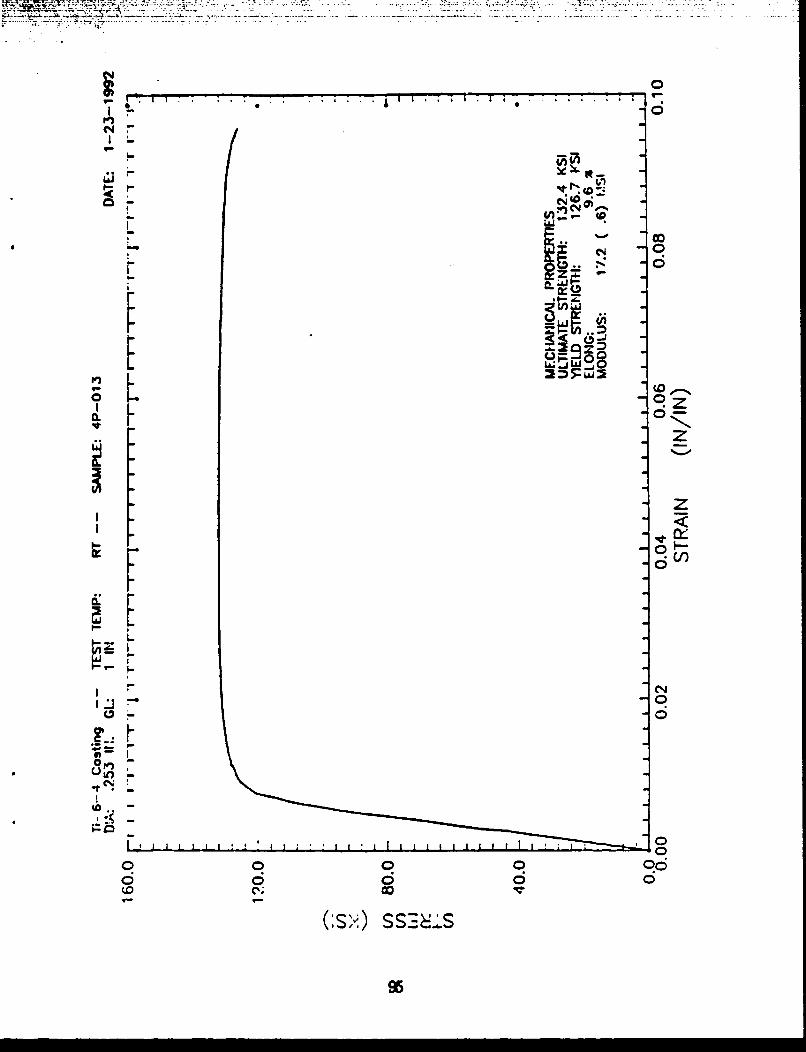
CC -'
000Li~
04
I-r
00
r 96
DA4 COM • O, BEARING, AND OMUAR DATA
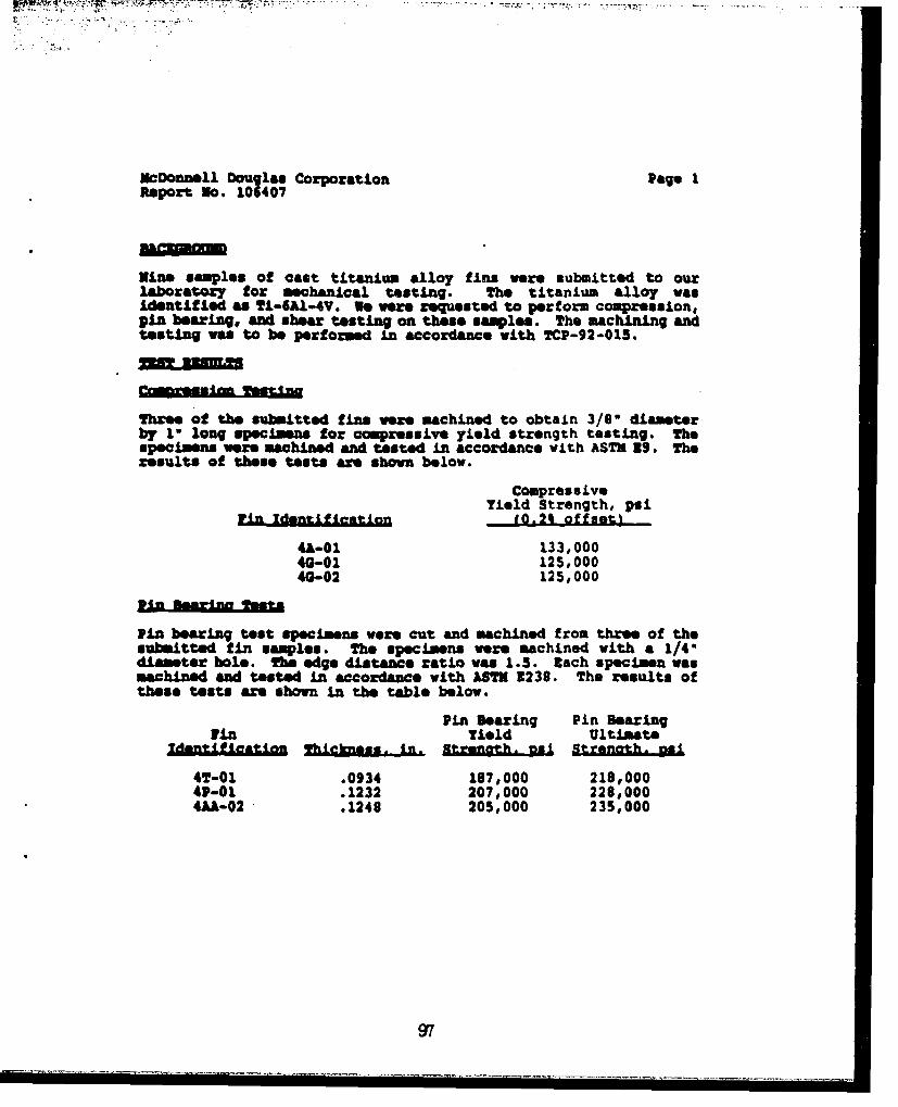
McDonnell Douglas Corporation Page IReport No. 106407
Nine samples of cast titanium alloy fins we"e submitted to ourlaboratory for mechantical testing. The titanium alloy wasidentifiLed as ti-SA1'.4v. We were requested to perform compression,pin bearing, and shear testing on these samples. The macahining andtesting was to be performed in accordance with TCP-92-0l5.
three of the submitted fins we"e machined to obtain 3/86 diameterby to long specimens for compressive yield strength testing. Thespecimens were machined and tasted in accordance with ASTH 39.* Theresults of these tests are shown below.
CompressiveYield Strength, psi
Win tentiieaton I.2% of fset)
"4-01 133,00040-01 125,00040-02 125,000
Pin bearing test specimens were cut and machined from three of thesubmitted fin samples. The specimens were machined with a 1/40diameter hole. The edge distance ratio was 1.5. lach specimen waswahined and tested in accordance with ASTE 3238. The results ofthese tests ae shown in the table below.
Pin Bearing Pin BearingFin Yield Ultimate
ZdASU.L~JnAkAa ShLckness. in Strengh. nal Steah_
4T-01 .0934 197,000 218,00001-01 .1232 207,000 228,0004AA-02 .1248 205,000 235,000
97

MCDonneM l Doug leI Corporation Page 2Report No. 101407
The remaining throe f W were out to obtain specimns for sheartet Ih MODiA VW iamblnd to the greatest thickness
posibl tobe btanedftme~h Mie, Me shear specimens weremaChIJd end teatod JA qO a with .ZLvM-810-1312, test 020 withreference to AM Paecooding, Iilm 53, $valuation of Iqngle-Shear IpeacLmen for Sheet material. T ,he moults of these toots areshown in the table below.
in Length of sheertdlnef[•mion hlu PatQ, SA -•e I.•
4U-02 .2437 .1486 08,3004V-02 .2470 .1506 92,3004T-02 .2481 .1486 94,400
Respectfully sulmitted,
flSZ1 £SUO JIAYBTS, fl.
mark A. Ensman, 1.3.Senior Metallurgical InLaneer
roAt/n
-l
..+

APPENDIX E
FRACTURE MECHANICS DATA
99

A!"PENDIX E
FRACTURE MECHANICS DATA
This appendix contains the results of testing compact tensionspecimens and bend specimens excised from the cast Ti-6A-4V fins. Datafrom constant-amplitude fatigue tests is also contained in this section.
100

McDonnell Douglas Missile Systems Co. Page 1Report No. 103983
Six nsmploe of titanium castings were eubmitted to our laboratoryfor mechanical testing. Th. testing wav performed in accordancewith 3ngineerLng Work Statement for ftaotuze Mechanics Testing forUse of Titanium CastLngs Without a Casting actorO, WS-MLT-7165.The mechanical tests we"e to include fatigue crack growth testingof three specimens per AM 3647, and plane-strain toughnesstesting of three specimens per I£2 3992 and 3399, and 3-curvedetermination per 3561.
Fatim Creack Orv• YaT~Ln
Three fatigue crack growth test escimens mor sachins4 from thesubmitted castings in accordance vh 3 A 647-S0. The specimenswere 0.50-C(T) spec ines r precracked at room temperatureusing an R-ratio of 0.1. ach specimen was tested under a constantload with increasing K condLtLons at rom temperature andwith an 1-ratio of 0.1. •raphs of crack length vs. the number ofcycles were developed using a clip gage to measurs the crackopening. These results are for al- three specimens in Figure No.2, and are individually presented in FLgur Nos. 4, 6, a S.
at specific cycle intervals, static load and COD measurements weredetermined to verify compliance of the specimens. The compliancemeasurements were converted to physical crack extension using Hudakand Sazena equations as followes
A/W-1.O01 - 4.6695 Ux + 10.46 0' - 236.02 0,3
+ 1214.9 U,' - 2.43.6 x
Where U, - (+ 1V/P4 .)*
Graphs of da/dn vs. Delta I were developed for ach specimen.These graphs are compiled in rigur•e o. 1. and a" individuallypresented as Figure Nos. 3, 5, and 7. Tables of the "ate obtainedduring each test are presented in Tables I thouagh 6.Fraeture tonunhaasa mar 3390
Three 0.400-C(T) compact fracture toughness specimens were cut andmachined from the submitted titanium castings. The specimens wereprecrackod and tested at +730o. The specimens were tested and theresults vere evaluated in accordance with A8M3 2399-90. Thspecific toot results are presented in Tables 7, 0, and 9, and asummary Ls shown on page 2.
101

NoDonnell D aouglas isLle Systims Co. Pag" 2Report So. 103983
Sml fL]a. sUAIaJmAX b- Of ?n ltd.
'4&A-01 70.6 I al,11 34AC-01 6.l ZIValiJd 340-02 ?0.0 low"I d 3
The test results of the three fracture toughness speciewmo wreevalua.t-e& AM 2361466 as Neults of each ups-lma ars
es~entd 91 10 troug 12 and a sumary is shown below.
4,A-01 122.7 140.9 •nvalId4AC-01 112.7? ZDnaid40-02 118.6 125.0 ZvaliJd
fto tesat results of the thawe iratuxe toughmme aOCmans woralso evaluated pe £A 3992-64. The esul•t of U004 evaluationsare sham In the table below.
4Wb-01 147.14AC-01 .117.94G-02 131.6
Respectfully submitted,
- ASW iMSzI, IW.
Sark A. UtuemanSenior Metallurgical InLneer
UAH/nb
102
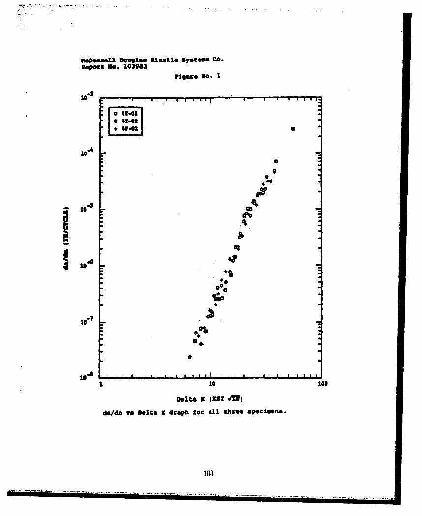

I~
I I * ~ OII I I 5 I I I 5
@o . EIS %goq1
N' " S0! "• - .."0-
4.*• -* a• ":',.
4. U .
*
.4.,

lepoct No. 103963
table Is ftet Data tCt Sample 4T-01
Ponco earn- ut 310
A&M EMU 42.41 U31 Dan: 07-09-199Tm.. limm 60.0 at? UODMLD 14.5 mat0 It =f Aix uaMm: 451
won mi~ 0.26 Is. iU 2 (Al) OU 0 IN2 .OM1 010 0.603 1"3 M i)* .0
SIMS (ha)S -AT L.26 -U.. SZW1.
- fl mY. . .
-AE LOD a 1.50 UsI. m Auu was 15 Llii.LOADhU MM a35 Lat. aUUEC .1.20 sects31388 lAMR a 1*
cu= MATMOM1nCTZo
FCM IM$ I3M.MA FAT== C3AM
VFALZDm mM M AM 364740.t
1. W 0 F Wlh*ih3 U A&5 AM A& n W3VLI.wui 0.006 M.o~ 0.25 * 3 .015
2. m max umi 3on muA mW um3 51 non =RUE Of aIM VALID
ALL VAUDITY CHECKS ARE VALID.
105

II
is el II sl~II
aim1 11 .
. I 'ii+i '"iiIII ';I+a"iI..ofl#4of5.+$6tqf- •-----
0004 00iO O 0 00 0 0
viol0.4044 ~ C
II m

inDONomll, Dougla fissile Systeis Co.
Report Bo. 1099
rigure 360. 3
03 a
aa
-10**
Delta (ra)
da/a v Dlta9 Oap fo sapl 4T01
W7.

I..I
S
'4
A4. , ,...*.w.,*...
.4..,4%.
*
4.
* 4.
.4. 1S3* 4.'4*1 4.
4.4.
4.
4.
4S
ii� a I� I.1 EW�'2 �UD
108

UODMSS11 Doglas MUta.ll Systems Co.Reoport go. 103063
ftble 3: tea Z at Is ml 4T=O22
SA 13 1 U t442-0 US? DMU: 0?.W4992TIMn flNO w- 60.0 gal2 NNOU.3 26.5 VUarmnt- NU~. mm.D~ 452
won mV - 0.99 IN. an a (12) - 0483I MNOWa usa) - 0.4128U.
I8 =MSD1 IACIU NAM 5.959 UI(892.U.)2in uIAm. .1
VAM L40aD 156 W3. LOAD - 1538.UL40 1M0 a 1U7 1US. 1UqwpvC - .1-2c Sons
US U21 - .1WTOU f
TAU.DZI1Ufh ii 122 AM =414M e*25 YL
in ~M u 2615. 80.2 0 3 ."S5
I.* in cu mmt MS IWA am3 11 no inK1 PU~n or Imm15
ALL VALIDITY CHWUC AME VALID.
W09

I looElmo~*q HAMM~ '
I-VA R41" "Ual IlI .. .0 n1'a;oI 00 OOOeg 0006 00000000 O 0 0 0 0
04 60 0 0 00 0004 0 0 6 u
64 00 Vo f- ~F4 V
110

7. .7,7
lcDmmelle D"14e8 missile Systems Co.Report No. 103983
rIgure nio. 5
10*
a
0
aa
00 0
110 UI
oa
toU
a
I 10 100
Delta a (KS! 41)daf/i vs Delta Z Graph for sample 4T-02.
111

II.
4.
Q 4.*
4. 04."I
11
! 4 .ii , : : : '*
4.
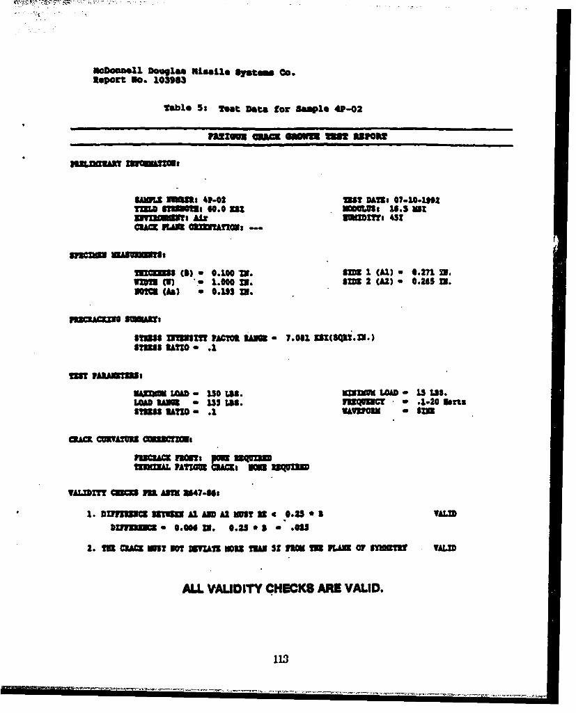
R*Port NO. 103963
Tabl* 5t teat Data foc Sa~ep1 4P02
mien am=~ em m unup
SAMSL UUmm 041.0 US? DAMI @7-104)0*2TZIM TMOUs o0.0 aZ wuis 16.5 atw I- MC MaTT Ai g= $ 3
U~S(s) a 0.100W 9= I (Al) a 4.271 Mf.I m~l - 1.000 M. $5202(Al) - 0.265 M.
813(As) *0.2*5 M.
53MS fl Sh!PACM~ "MS 7.061 %BK(1Q12.Z.)51315 SUGZ - .2
MTl AIANSTU:
amE LOAD - 150 LII. SEZW=UMLOD - 2.5 LI.5LAOA N so 255S LIS. mUQN=C - * 1-2lOefu31385 SUT - .2. WARUO3 a SI=
SIMIKAL PAT=gmmt fr
TAM=3 PUM M AM U47-00.
1. Dllflu3x 5135U AD A2 WIT U 0.25 1 T AMSb*min. 0.CON U. 0.250 * I.0us
2. MD MUA WIT 301 MYZll MWD TM* St In= ID U 01 O SKUSTft TAMI
ALL VFALIDITY CHECKS ARE VALID.

0 0 0 0 a ooooooov~~v~I
-I Is i o O*O1e*' " 5 0 0ea 0O 0 -
v~i SMO 0
095vv 1l-et,_ .. MOM IF
@U 9 ,03 0 1 Ie~ t! f -V
.4A
A ON A b 4
~v4 40 .ee04000MOZOO006,Sw M vw v w VV *
114

inanamOInl D0.uss IRIasLle Bratems Co.Report N. 103983
Figure go. 7
100
0-4
- 10 c
a
to -7
10 100
10.
Delta K (KS! i/N)
da/dn we Delta K Graph tog Sample 41-02
115

040
.. !
I \ .
a V -A 1
116

Mcfonnel.Sl Douglas MLsle Systems Co.
1R0eot no. 103963
table 7t Vt•recte !oM.uo Per =399I Sa)l 41A-Ol
* SUms: 4A,,.Ol SM. I sm. 'U,IU~l'L~s•4U•Z 3 4~•.
EI
- wt Iss IA on?2Tuii ;wCHs) 6%4* )VA1
aca
31393(1) Ill334iliImlifszmn (inr 224 2
""'CSA. LU•,.,A) -
V•A•ZOU M•C m-r=00 BHSCAMA L .- , IQ) W
VAL~pIT CM =s AMU SM
, 1,I:, -.,,,,"s" ' *1. 2,11 .1 62rOL 11•TBM
2 . A '3 0. , O R a. l , . t ; • , .s a l e (4. A0 t 0.45 0
7. 3VALID
S
a. -o. .,• •, (u,,)vAl :4Vi VALID
"*' TEST 18 INVALID PVER A8TM-EUN0 KG - 70.6 KSI(SQRI,) "'
317
~A 1 . VALID- -

3btalonll Douglas Misle. 11.m Unmn .Report no. 103963
Table B uoum1 1*R A&nm A%~a
-N -s, wA -.
mAl.
?ALDTT 5 MUMU9
1.3 PAU L.A
6.U 0.MI. U(STM) A
a ma DoOL 52A12. YMA&I
*'*~.4 TMS 0SIVLDPRAT.E2W KGVALID(SR.I.
Mr OfA AEm 118l*

aepwtt no. 103963
table 9: ftact*re tOuGOBOS ftc 93"399. SSl@-01
S s~~M-C(!) RhA
Ca LUS
I:B
Yguc 6U PUh3 =NMIYAM= IaMDm.o~' n
5. - @5dinll"
a. AG *12.?.3. "a~s. r"6 M 4 OR*.a
4.0A .- 45 AD0. mSS ?U.
44Ma! VALIDa
ii: A ggufh~ sui~sVALID
7. ;;.&PA4.01191P AI

ReDoinsell Seuglaa ulamile Systa Co.
Report N. 103983
2%ble 10: R-Cucye DoetcutmatiOUa Imaple 4AA-01
Gomm=~ to= vmRoAu gG6um io ft
TUTU Axe #73 1
ne1 m z * 50. 711
flowS 6. 74XII3U.U
3T 1T V iTl 3 31 AIT AM
~fi~a~ 4i~ jf 9

Reosusll D"Uglaissl U1.1.sate.. CO.ReOrOt No. 103963
table Ila a-Oute Dateruiaatio&. Reepl 410-a]l
is"~ (7)SDo a 2Ia U
fIlM AV. .75 1
4.67 XU .n
UUUU U1027 An $Me m
p T A wm a IVAN AM 1Km
1 11 1!! liii II . li d III I
121
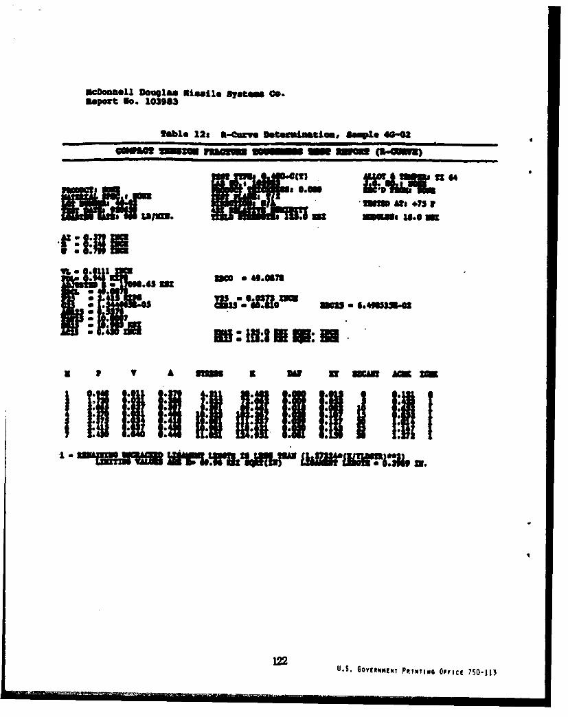
incbonell Omni" a lail. 8j.t. Co.Report No. 10390)
fable 12: 3k-Curve kteteiUmtim Sample 46-02
Erg~~.6 MatmAf 7
MOE Y ! AUUC K1:1111: jsw5m$:u's3ja. zu LM R4r.m 5ru.
U.S. GOYENIWNgN PRINTING OppICI 750-113
SUPPLEMENTARY
INFORMATION

DEPARTMENT OF THE AIR FORCEWRIGHT LABORATORY (AFMC1
WRIGHT-PArTERSON AIR FORCE BASE. OHIO
FROM: WL/MLSE Bldg 652 4 June 932179 Twelfth St Ste IWright-Patterson AFB OH 45433-7718
SUBJ: Error in Report WL-TR-92-4090 "Use Of Titanium Castings Without aCasting Factor"
TO: Distribution List
1. Please note that an error has been found in the subject. report on page 31. The erroris in the derived properties; compression, bearing, and shear.
2. Attached is a corrected table to replace the one in error.
3. If you have any questions concerning this, the point of contact is Steven Thompson
at (513) 255-5063.
Steven . Tho on 1 AtchT'hgineering and Design Data Distribution ListMaterials Engineering BranchSystems Support Division

Mechanical & Physical Properties ForTI-64, Investment Cast
Specification '_ _ _" _'Form Investment CastTemper Annealed, HIP'dThickness, ordiameter, inBasis Typical B AMechanical Properties
Ftu, ksi 131 128 125Fty, ksi 125 123 120Fey, ksiFsu, ksi 86Fbru, ksi 212(e/D = 1.5)Fbry, ksi 181(e/D = 1.5)e, percent 5.5Kc,ksi °in1/2
E, 103 ksi 17Ec, 1O3 ksiG, 103 ksi
mPhysical Properties:
w, lbs/inC, Btu/lboFK, Btu/hr*oftFa, 10"6in/in.F
Data source: Cast fins and step platesNumber of specimens: 115
FIGURE 17. SUMMARY OF ALLOWABLES FOR CAST TI-6AL-4V
31