important notice for users - augusta county service authority · although due diligence and...
TRANSCRIPT

1
2
Important Notice For Users:
Although due diligence and reasonable care has been taken to provide accurate and authoritative information about our pr oducts/services in this Training Manual as well as other documentation provided in connection with the subject training program, the u ser remains solely responsible for all consequences arising out of its use. This information is believed to be accurate and current as of the date of training; it is the user's responsibility to period ically check with Square D Co. headquarters (1415 S. Roselle Rd., Pal atine, IL 60067) for any updates reflecting introductions, changes, or o bsolescence of products and/or related functions. Competent profes sional advice or other expert assistance should always be obtained w ith respect to specific applications; it is the user's responsibil ity to ensure that the information in this documentation is appropriate fo r a particular application.
This Training Manual is a copyrighted publication o f Square D -Schneider Electric and is intended for use exclusiv ely by and for the benefit of authorized trainees. Reproduction of the contents of this copyrighted publication, in whole or in part, witho ut written permission of Square D is prohibited. Any reproduction of this Manual, in whole or in part (including pages or portions of pages), cop ying, duplication in any form (physical or electronic), or distribution to any third party is expressly prohibited without prior written consent of Square D Co.
Copyright 2003, Square D Co./ Schneider ElectricAll Rights reserved.

3
AC DRIVES AND SOFTSTARTS2812 Emerywood ParkwaySuite 231Richmond, Va, 23294Phone: 804-253-0302Fax 859-817-4261FAX: 859-372-1474PSG: 1-888-SquareD (778-2733)E-Mail: [email protected]
Paul Tegtman
Drives and Softstart Specialist
Merlin Gerin Modicon Square D Telemecanique

4
Square D AC Drives Support www.squared.com - Technical manuals on-line 1-888-SQUARED - 888- 778-2733 -
– Factory Technical Phone Support in Raleigh, NC
Factory stock up to 500 HP. 24 Hour Field Service line -1-888-SQUARED
– 1-888-778-2733

5
Square D Presents AC Drives
What is an AC Drive? –Drive and Motor Basics
Why should we use them?–Affinity Laws
Applications Application Considerations AC Drive Troubleshooting TechniquesAC Drive Troubleshooting Techniques Square DSquare D ’’s line of AC Drives & s line of AC Drives &
the Embedded Web Server the Embedded Web Server DemonstrationDemonstration

6
What is an AC Drive?

7
TERMINOLOGYTERMINOLOGY
AFCASDVFDVSDVSC
INVERTERFREQUENCY CONTROLLER
AC DRIVE
CONSTANT TORQUEVARIABLE TORQUE
CONSTANT HORSEPOWER
AFCASDVFDVSDVSC
INVERTERFREQUENCY CONTROLLER
AC DRIVE
CONSTANT TORQUEVARIABLE TORQUE
CONSTANT HORSEPOWER
8
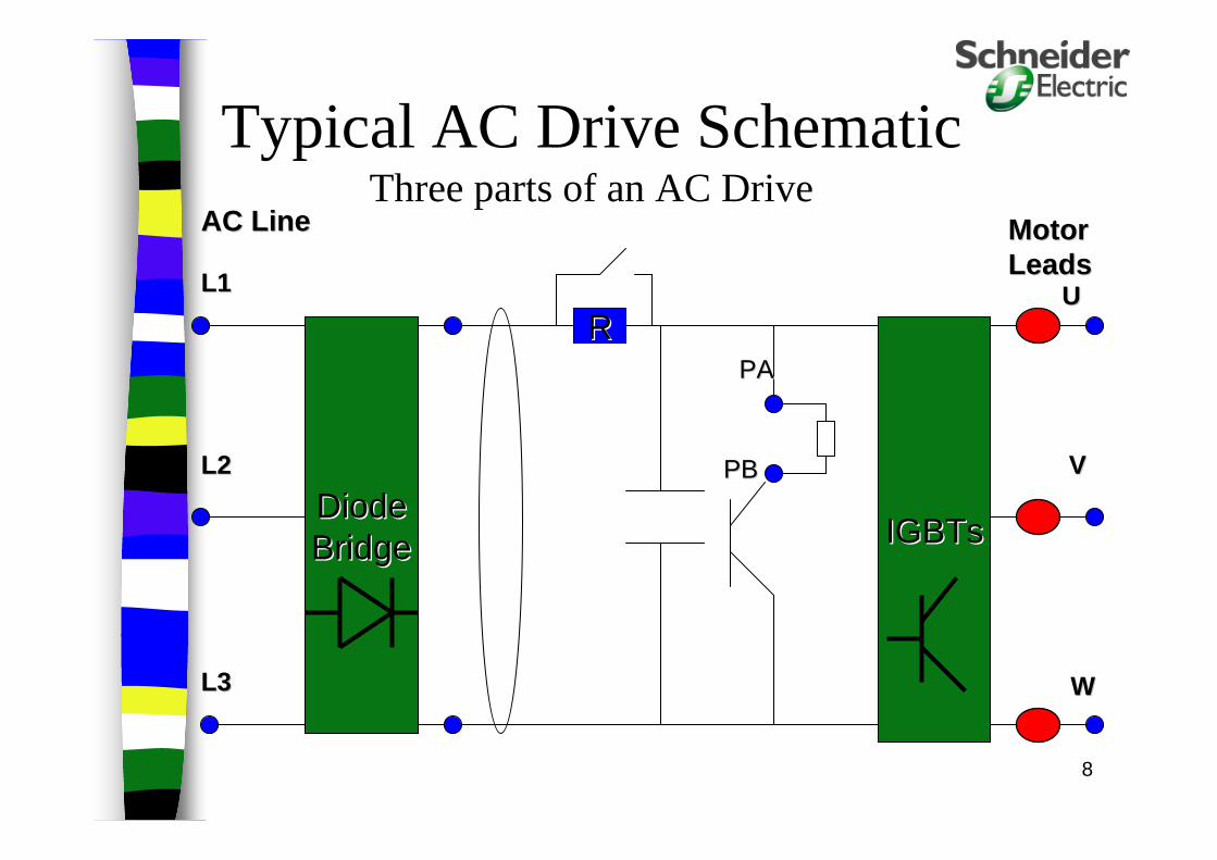
Typical AC Drive SchematicThree parts of an AC Drive
DiodeDiodeBridgeBridge IGBTsIGBTs
L1L1
L2L2
L3L3
UU
VV
WW
PAPA
PBPB
RR
AC LineAC Line MotorMotorLeadsLeads
9
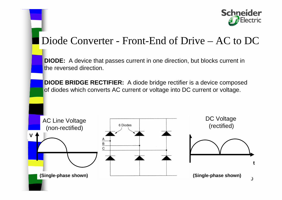
DIODE: A device that passes current in one direction, but blocks current inthe reversed direction.
DIODE BRIDGE RECTIFIER: A diode bridge rectifier is a device composedof diodes which converts AC current or voltage into DC current or voltage.
V
t
V
t
AC Line Voltage(non-rectified)
DC Voltage(rectified)
(Single-phase shown)(Single-phase shown)
Diode Converter - Front-End of Drive – AC to DC
10
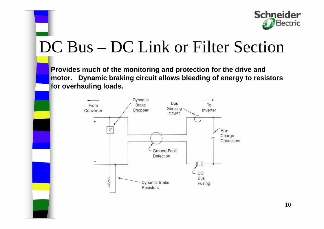
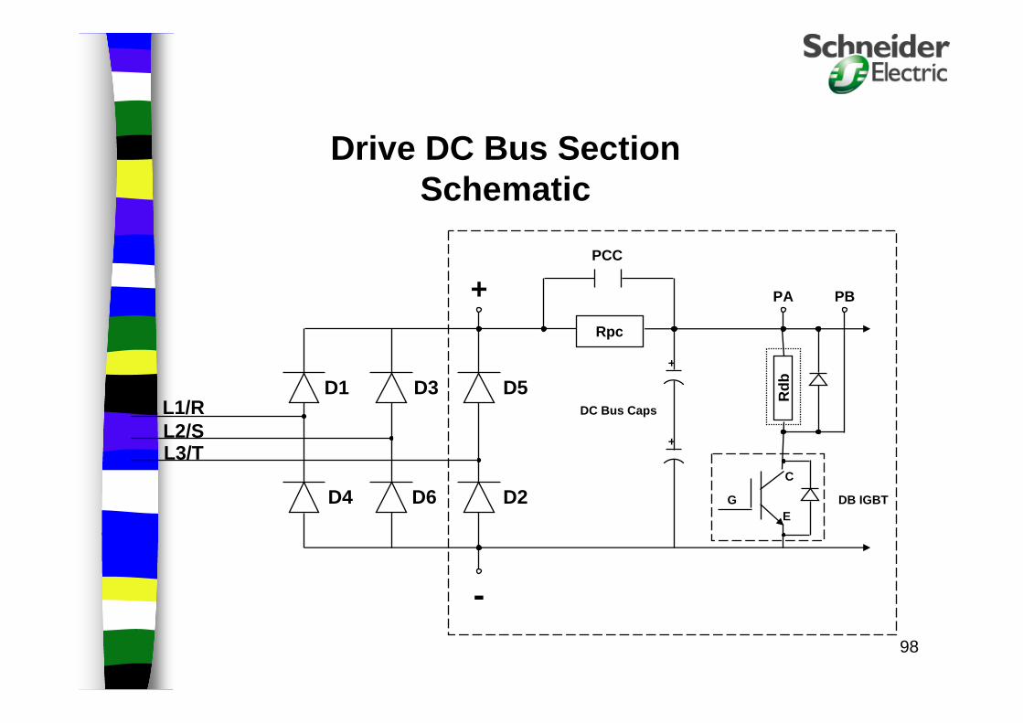
Provides much of the monitoring and protection for the drive andmotor. Dynamic braking circuit allows bleeding of energy to resistors for overhauling loads.
DC Bus – DC Link or Filter Section

11
INVERTER: An inverter is a device which converts DC energy into three channels of AC energy that an induction motor can use. Typically these are IGBT’s.
V
t
V
t
DC Voltage(non-inverted)
AC Voltage(inverted)
(Three-phase average shown) (Single-phase shown)
INVERTERS – Back-End of Drive – DC to AC

Pulse Width Modulated Waveform Controls the width of the pulses, many times per ha lf cycle to
manufacture a sinusoidal output to the motor.
Even though the RMS value of voltage is lower, the drive is still sending pulses of 650VDC power to the motor.

13
Motor Basics
14
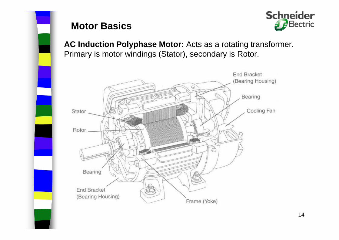
AC Induction Polyphase Motor: Acts as a rotating transformer. Primary is motor windings (Stator), secondary is Rotor.
Motor Basics
15
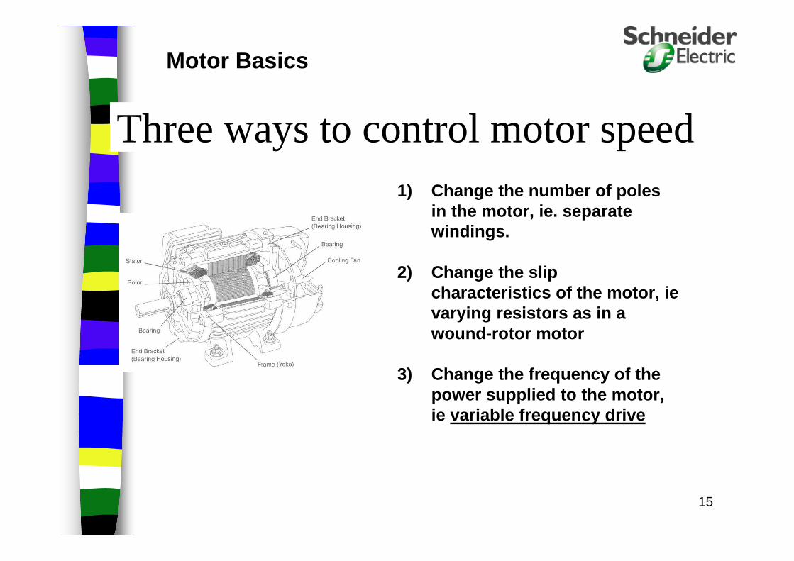
1) Change the number of poles in the motor, ie. separate windings.
2) Change the slip characteristics of the motor, ievarying resistors as in a wound-rotor motor
3) Change the frequency of the power supplied to the motor, ie variable frequency drive
Three ways to control motor speed
Motor Basics

16
Synchronous Speed = 120 * frequency# poles
= 120 * 60 Hz = 1800 rpm 4
1) Stator receives current from the drive which creates a rotating magnetic field.
2) This rotating field moves the rotor.
3) The frequency is how often the current flows through the stator.
4) Controlling the frequency to the stator controls the motor speed.
5) Controlling the voltage and frequency, controls the torque capability of the motor.
Synchronous Speed

17
Slip – Generating Torque
1) Once the motor is loaded it will not be able to reach synchronous speed.
2) The difference between synchronous speed and full-load motor speed is Slip.
3) (i.e. 1800 rpm synchronous speed, 1780 full load speed)
4) Induction motors are classified by their slip characteristics as shown in speed vs torque curves. (Designs A, B, C or D).
Motor Basics
18
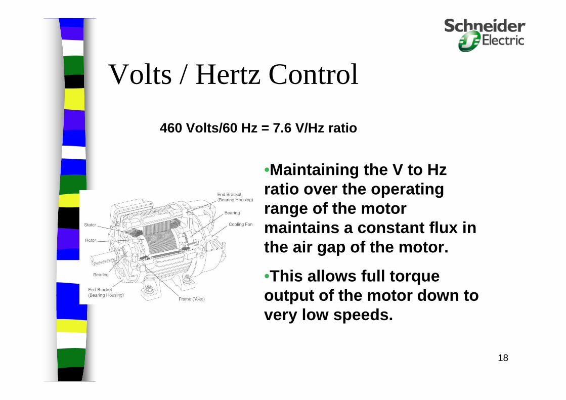
460 Volts/60 Hz = 7.6 V/Hz ratio
Volts / Hertz Control
•Maintaining the V to Hz ratio over the operating range of the motor maintains a constant flux in the air gap of the motor.
•This allows full torque output of the motor down to very low speeds.

19
Why do we use AC Drives?
20
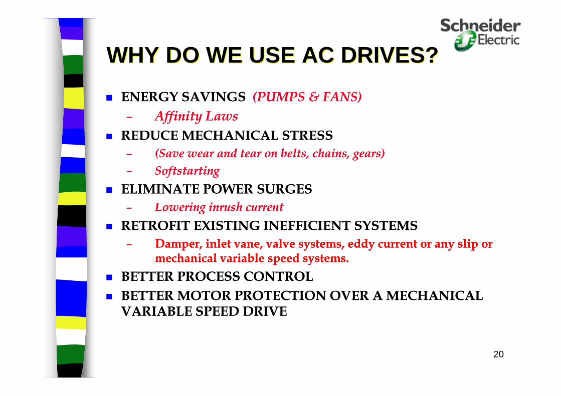
WHY DO WE USE AC DRIVES?WHY DO WE USE AC DRIVES?
ENERGY SAVINGS (PUMPS & FANS)
– Affinity Laws
REDUCE MECHANICAL STRESS
– (Save wear and tear on belts, chains, gears)
– Softstarting
ELIMINATE POWER SURGES
– Lowering inrush current
RETROFIT EXISTING INEFFICIENT SYSTEMS
– Damper, inlet vane, valve systems, eddy current or any slip or mechanical variable speed systems.
BETTER PROCESS CONTROL
BETTER MOTOR PROTECTION OVER A MECHANICAL VARIABLE SPEED DRIVE

21
Affinity Laws & Energy Savings
Apply only to Variable Torque Loads
Flow is directly proportional to Speed Pressure is proportional to the Square
of Flow(Speed) Power is proportional to the Cube of
Flow(Speed)– i.e. At 50% of full speed, the application will
require12.5% of full power.
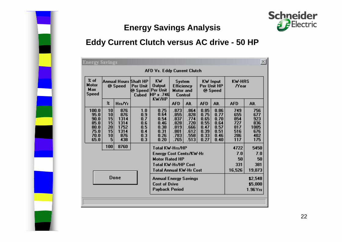
22
Energy Savings Analysis
Eddy Current Clutch versus AC drive - 50 HP
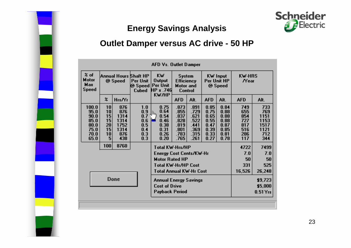
23
Energy Savings Analysis
Outlet Damper versus AC drive - 50 HP
24
Reducing Mechanical Stress with AC Drives
Life of bearings are extended, since the motor is running at lower speeds
Wear on impellers and blades are reduced due to lower back pressures.
Audible noise of fans and pumps are reduced AC Drives offers a more precise way of
controlling the system
Life of V-Belts are extended due to a soft-start

25
– Input phase failure– Phase rotation– Brown out or under voltage protection. If you have a brown
out the motor will burn up unless you have this bui lt into somewhere else in the system.
– With a bypass, you have a back up. How do you bypas s the mechanical speed drive? If it is down, you are Down !!
– Instantaneous over current protection.– Over-voltage protection– Power factor correction!! You are looking at .97 or better
power factor. Standard motor is in the .85 area at full load.– Output phase protection– Short Circuit protection– Ground Fault protection.
BETTER MOTOR PROTECTION OVER A MECHANICAL VARIABLE SPEED DRIVE

26
APPLICATIONS

27
VARIABLE TORQUE LOAD TORQUE VARIES AS THE SQUARE OF THE SPEED
60 Hertz0 speed
torque
100 %
AC DRIVE MUST BE SIZED FOR MOTORFULL LOAD AMPERESWITH A SHORT TIME OVERLOAD RATING OF 110% FOR 1 MINUTE
Torque Load Line
Load CharacteristicsLoad Characteristics
28
Variable Torque Applications
Centrifugal Fans
Centrifugal Pumps
Centrifugal Chillers

29
VT Loads are found where?
Office Buildings, Water Plants, Wastewater Plants:
Equipment:
Water Pumps
WasteWater Pumps
Cooling Towers
Chill Water Pumps
Condenser Water Pumps
Air Handlers
30
RHORHO
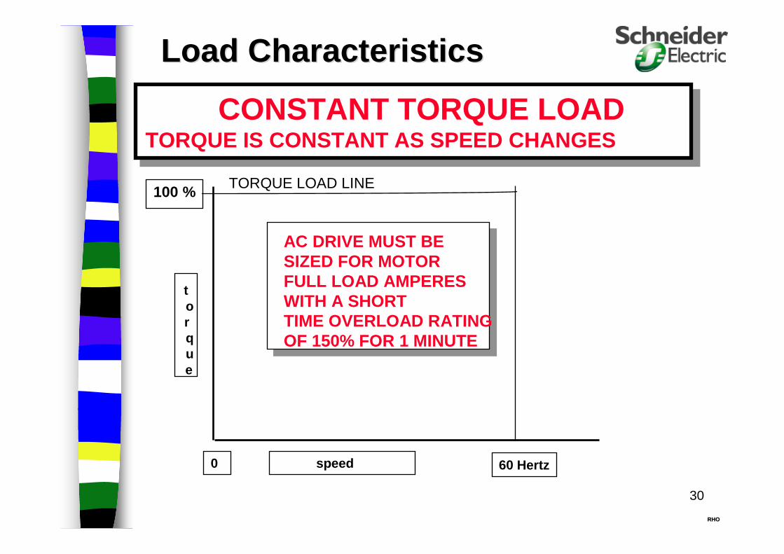
CONSTANT TORQUE LOAD TORQUE IS CONSTANT AS SPEED CHANGES
60 Hertz0 speed
torque
100 %
AC DRIVE MUST BE SIZED FOR MOTORFULL LOAD AMPERESWITH A SHORT TIME OVERLOAD RATING OF 150% FOR 1 MINUTE
Load CharacteristicsLoad Characteristics
TORQUE LOAD LINE
31
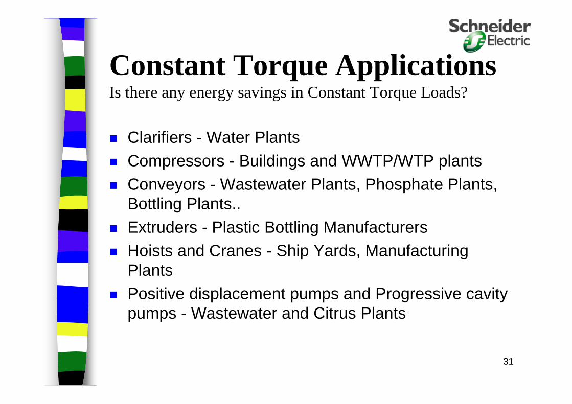
Constant Torque ApplicationsIs there any energy savings in Constant Torque Loads?
Clarifiers - Water Plants Compressors - Buildings and WWTP/WTP plants Conveyors - Wastewater Plants, Phosphate Plants,
Bottling Plants.. Extruders - Plastic Bottling Manufacturers Hoists and Cranes - Ship Yards, Manufacturing
Plants Positive displacement pumps and Progressive cavity
pumps - Wastewater and Citrus Plants
32
RHORHO
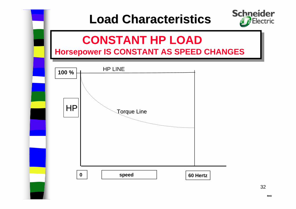
CONSTANT HP LOAD Horsepower IS CONSTANT AS SPEED CHANGES
60 Hertz0 speed
100 %
Load CharacteristicsLoad Characteristics
HP LINE
Torque LineTorque LineHPHP
33
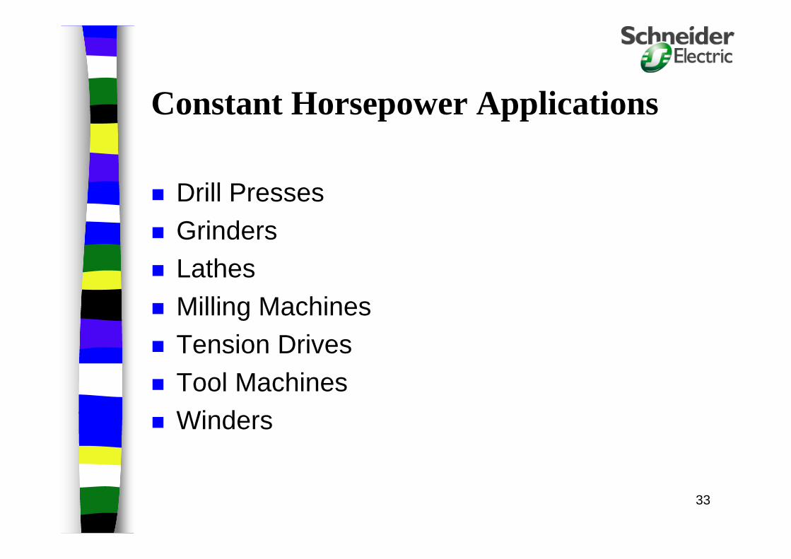
Constant Horsepower Applications
Drill Presses
Grinders Lathes
Milling Machines Tension Drives
Tool Machines Winders

34
AC DriveApplication Considerations

35
Application Considerations
Sizing an AC drive -– HP vs. Amperage (& volts)
• Watch out for Low RPM motors. (720/900/1200)• Low RPM motors have higher amps than 1800 rpm
motors.• Motor Nameplate data vs. Actual Data, take
measurements
36
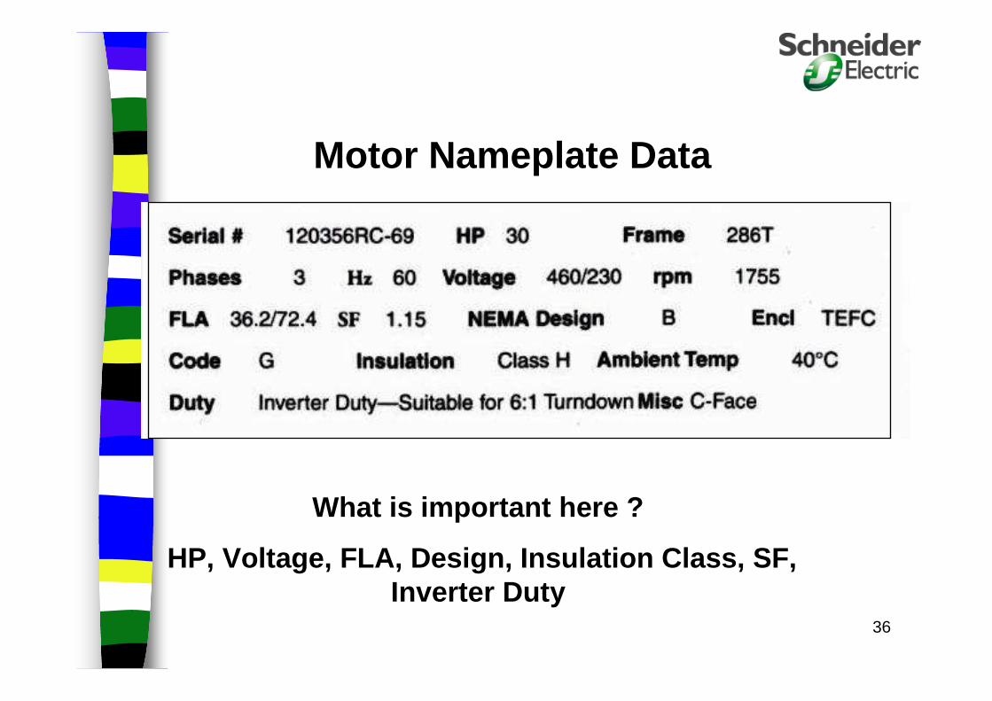
Motor Nameplate Data
What is important here ?
HP, Voltage, FLA, Design, Insulation Class, SF, Inverter Duty

37
Application ConsiderationsApplying AC Motors To AC Drives
Motor Insulation and Construction– Inverter duty motors have a higher insulation
rating. 1600 Volts vs. Standard motors, 1000 volts.
– Inverter duty motors are sized per the application, Variable torque vs Constant torque.
38
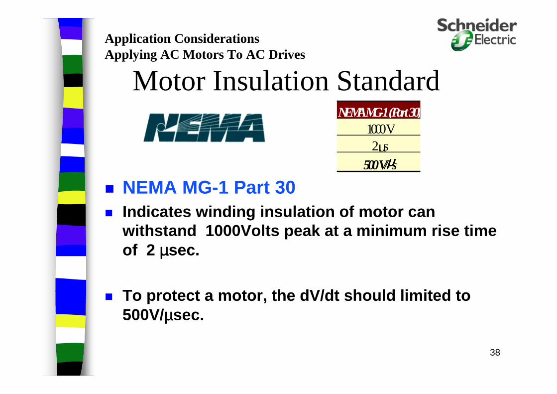
Motor Insulation Standard
NEMA MG-1 Part 30 Indicates winding insulation of motor can
withstand 1000Volts peak at a minimum rise time of 2 µµµµsec.
To protect a motor, the dV/dt should limited to 500V/µµµµsec.
NEMA MG-1 (Part 30)1000 V2 µs
500 V/µµµµs
Application ConsiderationsApplying AC Motors To AC Drives
39
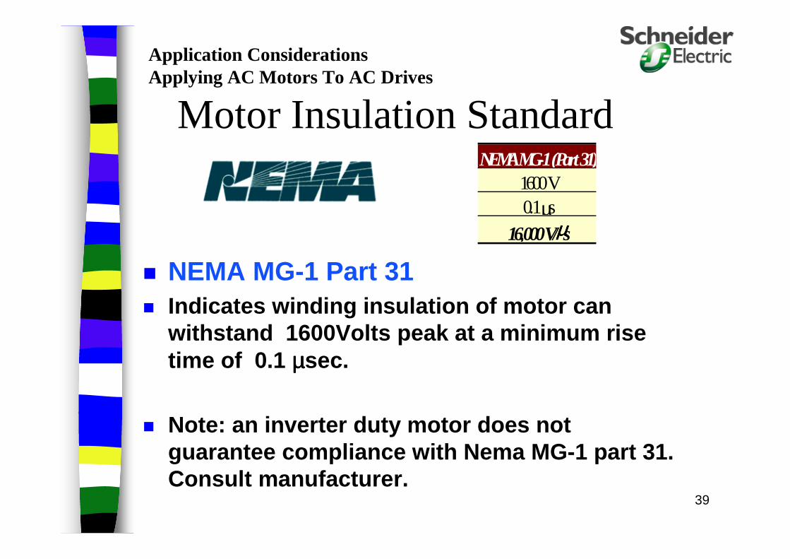
Motor Insulation Standard
NEMA MG-1 Part 31 Indicates winding insulation of motor can
withstand 1600Volts peak at a minimum rise time of 0.1 µµµµsec.
Note: an inverter duty motor does not guarantee compliance with Nema MG -1 part 31. Consult manufacturer.
NEMA MG-1 (Part 31)1600 V0.1 µs
16,000 V/µµµµs
Application ConsiderationsApplying AC Motors To AC Drives
40
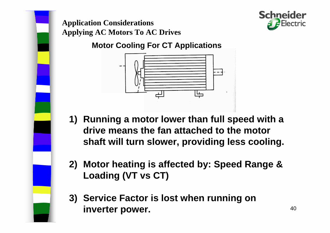
1) Running a motor lower than full speed with a drive means the fan attached to the motor shaft will turn slower, providing less cooling.
2) Motor heating is affected by: Speed Range & Loading (VT vs CT)
3) Service Factor is lost when running on inverter power.
Motor Cooling For CT Applications
Application ConsiderationsApplying AC Motors To AC Drives

41
Motor Cooling Solutions For CT Applications
1) Use a separately controlled cooling fan.
2) Set your minimum speed above zero
3) Duct cooled air to the motor.
Application ConsiderationsApplying AC Motors To AC Drives
42
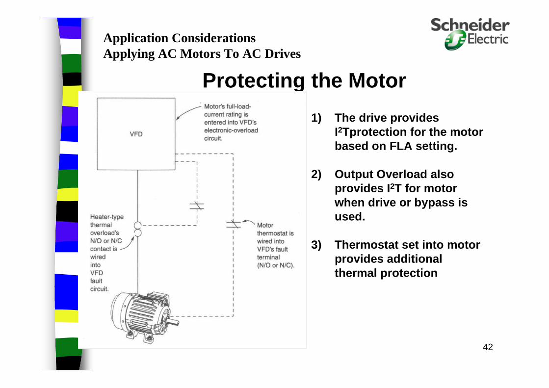
Protecting the Motor
1) The drive provides I2Tprotection for the motor based on FLA setting.
2) Output Overload also provides I2T for motor when drive or bypass is used.
3) Thermostat set into motor provides additional thermal protection
Application ConsiderationsApplying AC Motors To AC Drives

43
Motor Lead Length from AC drive will determine the voltage level at the motor.
Special Considerations – Long Lead Lengths– Over 100’ for up to 100 HP
– Over 200’ for 125HP and above
– Reflected Waveform can cause voltage doubling at th e motor
– Solutions include:
• Lowering the carrier frequency of the drive
• Specify and purchase NEMA MG-1, Part 31 motors
• Install output reactors (Also reduces ground fault) or output filters (Also used to protect older motors).
• Utilize VFD rated cable, Belden, Shawflex, Olflex
Application ConsiderationsApplying AC Motors To AC Drives

44
Z(cable) = Z(motor)No Reflection
Z(cable) > Z(motor)Current is reflected at the motor
Z(cable) < Z(motor) (Typical for AC Drive/Motor)
Voltage is reflected at the motor(What do electricians do for long motor lead runs?)
Reflected Wave Phenomenon
Application ConsiderationsApplying AC Motors To AC Drives
45
Carrier Frequency– Higher carrier frequency can cause audible
motor noise
• Increasing above 8 kHz makes it inaudible to humans
– Higher carrier frequency stresses motor
– Higher carrier frequency makes shaft voltage build-up more likely (Typically over 8 Khz)
– Higher carrier frequency makes reflected waveform more likely
Application ConsiderationsApplying AC Motors To AC Drives
46
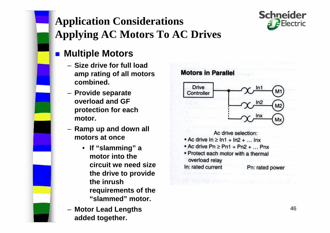
Multiple Motors– Size drive for full load
amp rating of all motors combined.
– Provide separate overload and GF protection for each motor.
– Ramp up and down all motors at once
• If “slamming” a motor into the circuit we need size the drive to provide the inrush requirements of the “slammed” motor.
– Motor Lead Lengths added together.
Application ConsiderationsApplying AC Motors To AC Drives
47
Shaft Voltage Build -Up– Voltage build-up of 5-30VDC on the shaft is
possible with higher carriers (above 8 Khz).
– This will either bleed away or flash to ground
– Typical flash point is bearings
• This will pit the bearing and the race
– Common solutions include:
• Decrease carrier frequency from drive
• Ground shaft with a brush
• Use conductive grease
• Ceramic bearings
Application ConsiderationsApplying AC Motors To AC Drives
48
Application Considerations
Power Circuits– Open Units - Non-Combo– Input Circuit Breakers - Combo– Bypasses -
• 3 contactor • dual disconnects• Nema rated contactors (What is a Nema Rated
Contactor?)• softstart bypass .

49
Combo with Bypass

50
Application ConsiderationsEnvironmental Considerations
– Rating for the Enclosure– Indoor, Nema 1, Nema 12– Outdoor, Nema 3R, Nema 4, Nema 4x, Direct Sun?– Ambient Temperature
• Most drives are rated 0-40 degrees C Ambient
• Derating is required above 40 degrees C.(50 C insid e the Enclosure)
• Heating is required below zero degrees C.

51
Environmental Considerations Humidity
– Most drives are rated for 95% humidity, non-condensing
– Leaving the drive energized should provide enough heat to minimize condensation unless ambient drops below zero degrees C
Application Considerations

52
Nema3R Cabinet

53
Environmental Considerations
Altitude– Most drives are rated up to 3300 feet above
sea level
– Derating is required above 3300’ due to thinner air
Application Considerations

54
Application ConsiderationsInstallation and Wiring
Input Power wiring– Can be grouped with other 460/230 VAC
equipment
Output Motor Leads – Must be separated by space
• (PVC conduit - 12” spacing) and shielding using rigid conduit or shielded wiring (3” spacing).
55
Application ConsiderationsInstallation and Wiring
Control Interface - Analog vs. Digital– Relays and analog signals, Start, Stop, Speed
reference, Fault feedback vs. – Serial communications - Modbus, Modbus
plus, Modbus TCP/IP (Ethernet), etc ..
Signal Wiring -– Must be separated from power wiring or at
right angles when crossing power wiring. Shielding is required for ma signals and serial communication. Ground shield at source.

56
Special Considerations–Single-Phase in Three Phase Out
–Smaller drives are rated for this already
–For larger HP’s• De-rate the drive typically by one size
– Check input diode bridge amp rating (1.732 x motor full load rating)
• Add line reactors (For continuous duty, not necessary for intermittent duty)
• Turn off input phase loss
Application Considerations

57
Application Considerations Harmonics and Abatement Techniques
– IEEE Guidelines• 519-1981- Voltage Distortion• 519-1992- Current and Voltage Distortion
– Defining PCC. – Utility vs. Generator Supply.
– Abatement - Cost vs Benefit.• Line Reactors• Passive Filters - Tuned, Broadband• Multi-pulse inputs, 12,18,24• Active Filters

58
Power Quality and Harmonic Requirements
– Line Reactors
– Multi-Pulse
– Passive Filters
– Active Harmonic Injection
Application Considerations
Without Impedance
“Stiff” Distribution feeder (High Fault Current)

59
Impedance reduces the distorted current demanded from the AC line
Without Impedance
“Stiff” Distribution feeder (High Fault Current)
With Impedance
“Soft” Distribution feeder (Low Fault Current)
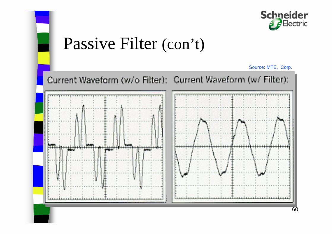
60
Source: MTE, Corp.
Passive Filter (con’t)

61
Multi-Pulse/Active Filter Waveform Comparisons
18-Pulse with integral mountedFork Transformer
or Active Filter
12-Pulse with separate 3-winding Isolation Transformer
12-Pulse with Auto-transformer same as input reactor

62
AC DriveTroubleshooting
Techniques

63
Thank You for YOUR Time!

64
Typical Technology : layout of elements
Power card
Keypad Display
Input Rectifier Diode Module
F1 F2 F3
0 RUN STOP
ENT
ESC
1 2 3
4 5 6
7 8 9
Heat sink Control cardApplication software card
(PCMCIA)
Communicationcards
I/O extensioncards
Ventilation fan
Power terminals
Control cardterminal strip
LEDIndicators
IPM orIGBT’s
RYG
65
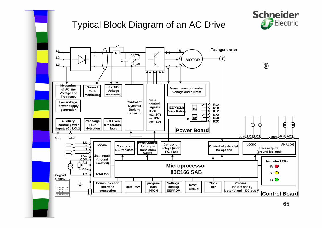
ATV 66 ® block diagram
R
PBPA+
-
U
V
WC
DBMOTOR
Control ofDynamicBraking
transistor
DC Bus Voltage
measuring
IPM Over-temperature
fault
PrechargeFault
detection
GroundFault
monitoring
(EEPROM)Drive Rating
Measuringof AC line
Voltage andFrequency
Low voltagepower supply
generation
Auxiliarycontrol power
inputs (CL1,CL2)
Measurement of motor Voltage and current
Power Board
LOGIC
User inputs(groundisolated)
ANALOG
LOGIC ANALOGUser outputs
(ground isolated)
Communicationinterface
connection
Control ofrelays (user,
PC, Fan)
PWM controlfor outputtransistors
(ASIC)
Control forDB transistor
Control of extendedI/O options
data RAMprogram
dataPROM
Settings backup
EEPROM
ClockmP
Resetcircuit
Control Board
Process:Input V and F,
Motor V and I, DC bus V
Microprocessor80C166 SAB
Gate control signalsIGBT(sz. 3-7)or IPM(sz. 1-2)
R1
R2
F1 F2 F3
0 RUN STOP
ENT
ESC
1 2 3
4 5 6
7 8 9
Indicator LEDs
R
Y
G
T
Tachgenerator
. .. .. .. .
LI1LI2LI3LI4
AI1
AI2
COM+24v
+10v
Keypaddisplay
CL1 CL2 LO1 LO2 AO1 AO2com com
R1AR1BR1CR2AR1BR2C
L3
L2
L1
Typical Block Diagram of an AC Drive

66
Power terminal blocks
R1A R1B R1C R2A R2B R2C
R1A R1B R1C R2A R2B R2C
Power Card Frame 3, 4, 5
Power Card Frame 1 and 2
GL21
CL1
L22
CL2L1 L2 L3 + - PA PB
U V W
T1 T2 T3
CL1 CL2 L1 L2 L3 + - PA PBU V W
T1 T2 T3
G
Ground terminals
Controlcircuit supply backup
Power circuitsupply
DCbus
Brakingresistors
Motor supply
Fault relay contacts
Programmablerelay output
Plug-in terminal blocks
67
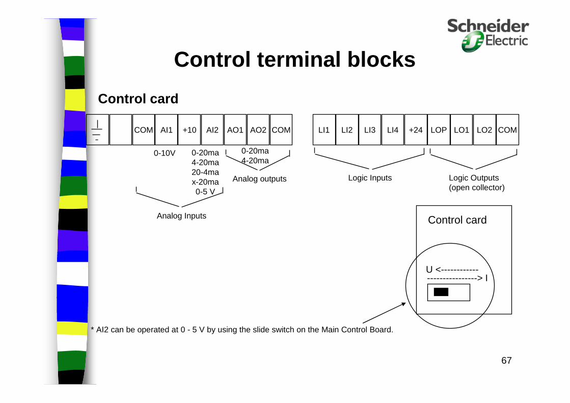
Control terminal blocks
LI1 LI2 LI3 LI4 +24 LOP LO1 LO2 COMCOM AI1 +10 AI2 AO1 AO2 COM
Logic Inputs Logic Outputs(open collector)
Analog outputs
0-10V
Analog Inputs Control card
----------------> IU <------------
Control card
0-20ma 4-20ma 20-4ma x-20ma 0-5 V
0-20ma 4-20ma
* AI2 can be operated at 0 - 5 V by using the slide switch on the Main Control Board.

68
Things to look for in an installation that may cause AC drive nuisance tripping and/or failures
69
AC Drive Installation and Wiring
All wiring to and from the drive should be in metallic conduit
Each drive’s output power wiring must be run in it’s own metallic conduit
Do not run Drive input and output power wiring in the same conduit
70
AC Drive Installation and Wiring
Cross wiring of different classes at right angles to each other to eliminate capacitive effects and coupling of electrical noise between circuits.
In-line filtering of conducted emissions (EMI) may be required in some installations.
RFI - AC Drive not in metallic enclosure
71
AC Drive Installation and WiringPower System Branch Circuit Connections
Size feeder cables, disconnects, and protective devices per drive input current, not motor FLAExample:20 HP Drive input current = 44.8 amps on 65K amps fau lt
current feeder.20HP Motor FLA = 27 ampswith an input reactor or higher input impedance (lowe r fault
currents), input amps will be 27 amps.
The feeder and disconnect means should then be sizedper NEC Art. 430-2 using the Drive Input Current Ratin g
As impedance of system increases, input current decreases.

72
AC Drive Installation and Wiring
Any relay coils or solenoids connected to the output of the Drive should be supplied with transient suppressers
Analog inputs and outputs required twisted pair or shielded cable. Terminate shield at Drive terminal marked “S” (ground potential).
Input sequencing contacts or signal switching contacts, must be rated for proper voltage and amps. (High and low).
Control Wiring Precautions

73
AC Drive Installation and Wiring
Do not connect lightning arrestors or Power Factor Correction capacitors on the output of the drive
Output cable lengths greater than 100 Ft. may require a load (output) reactor
Do not use mineral impregnated cable on the drive output as it has a very high self-capacitance
Output Wiring Precautions
74
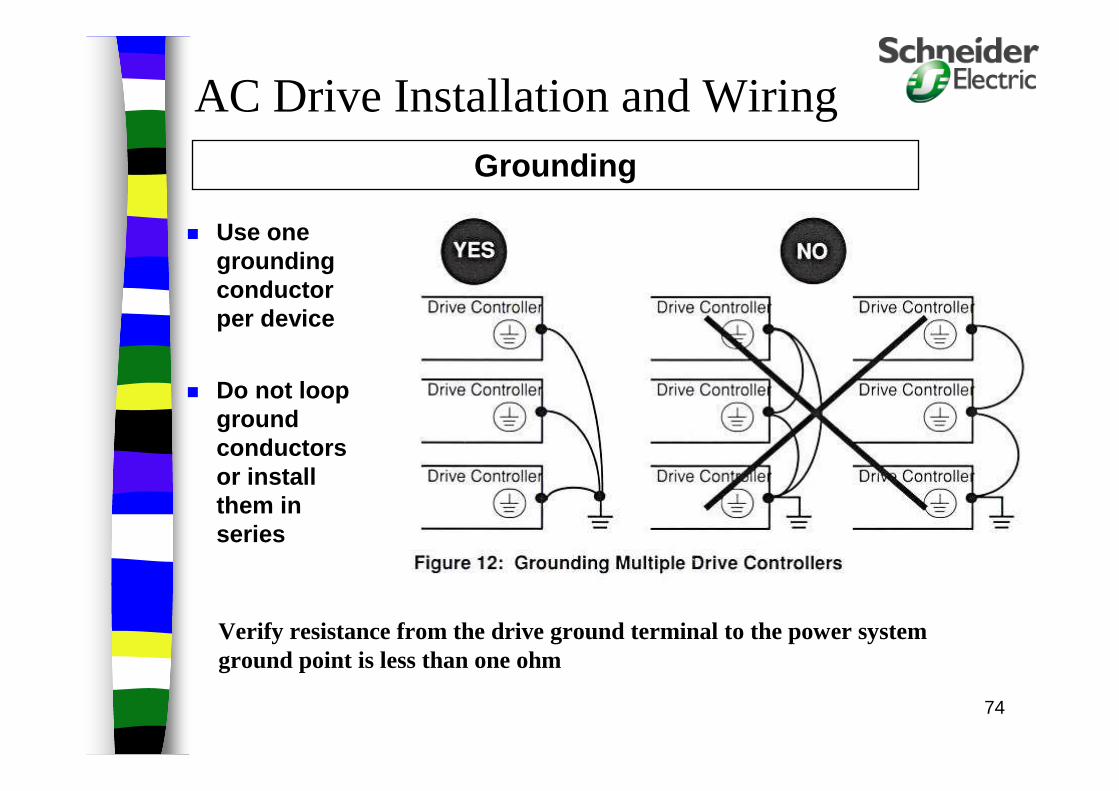
Use one grounding conductor per device
Do not loop ground conductors or install them in series
Verify resistance from the drive ground terminal to the power system ground point is less than one ohm
AC Drive Installation and WiringGrounding

75
Separation of VFD Wiring in Cable Trays:
* Separate conduit runs if not using cable tray.
Communication Cables Wiring Wiring Wiring
3" 3" 6"
24V dc/ac 120Vac 460Vac
cont
rol
sign
al/c
ontr
ol
pow
er
com
ms
76
Wiring Practice Overview:Remember the “DO’s and DON'Ts” in wiring Drives: DO’s:
– Understand the different wiring classifications i.e. power, control, signal level, and communications
– Separate control wiring from power wiring. – Separate low level analog signals from control and power wiring.– Use shielded cable for all analog signals.– Cross wire runs of different wiring classes at right angles.– Run a ground wire from the origin of the power source to each
drive DON'Ts:
– Do not run multiple output power cables from multiple VFD’s in the same conduit.
– Do not ground the shield of analog signal shielded cable at bothends.

77
AC Drive Preventative Maintenance
Check the condition and tightness of connections.
Make sure ventilation is effective and that the temperature around the drive is at an acceptable level.
Remove dust and debris if necessary.

78
Basic Troubleshooting

79
Troubleshooting Process
1. GatherInformation
4. Determine Malfunctioning
Sub-system
3. AnalyzeSystem Faults
2. Locate SystemEquipment
5. PerformSub-system Diagnostics
6. Repair or Replace
Sub-assembly
7. Verify System Operation

80
Read and heed the Danger, Warning, and Caution labels in the Drive User’s manuals
Insure that the equipment is properly grounded
Use only “known-good” test instruments and probes; no frayed or broken test leads
Wear protective eyewear, thick rubber soled shoes, and no jewelry
Beware of ground “floated” test equipment
Remember: a small drive is equally as dangerous as a bigger one
Safety Considerations

81
Fault IndicatorsMessages
Check in your manual for these fault codes and/or corrective actions.

82
83
Common Fault CausesThe AC Drives is where most people point to, however:
Poor connections or open/broken conductors
Unintended grounds or ground paths in power and control wiring
Electrical noise
Power system disturbances and interruptions
General incorrect wiring during installation and retrofits
Motor failure, or other mechanical system problems
84
Record Drive Model number including any options Find Voltage and Current ratings Note software revision level Get manufacturing Date Code (6W.... or 86....) Record controller, motor, and auxiliary equipment
nameplate data Record the Faults, including past faults in the fault
history.
Fault Log - Drive Information
TROUBLESHOOTING TIPS TROUBLESHOOTING TIPS

85
Is the complaint “the drive doesn’t work as expected” or, “the drive trips”?
What was the machine doing when the drive tripped?
Had it been working properly? Were there any unusual conditions?
» Excessive heat, cold, moisture, lightning storms, power surges/glitches, etc.?
Had the problem occurred before? Has the application changed?
Fault Log - Operating Information
TROUBLESHOOTING TIPS TROUBLESHOOTING TIPS

86
Look around and get a feel for the operating environment» Temperature, moisture/condensation, dust,
corrosive chemicals, etc. Observe the unit for physical deterioration: rust,
melted parts, burn marks, etc. Check for proper installation of unit Check fans for operation; listen for any strange
sounds during operation Verify drive settings are correct for the
application
Fault Log - Environmental Checks
TROUBLESHOOTING TIPS TROUBLESHOOTING TIPS

87
TROUBLESHOOTING TIPS TROUBLESHOOTING TIPS
CALL TECHNICAL SUPPORT AFTER YOU HAVE DONE ALL OF THE INFORMATION GATHERING!

88
Electrical Checks

89
Thank You for YOUR Time!
90
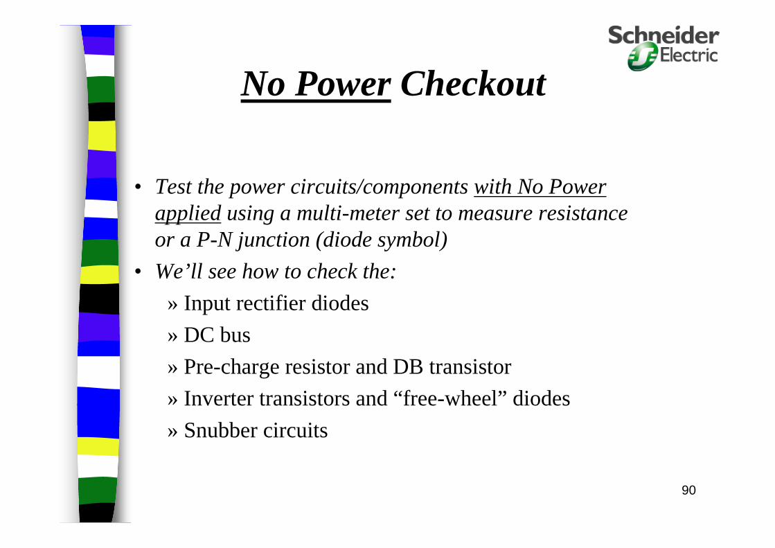
No Power Checkout
• Test the power circuits/components with No Power appliedusing a multi-meter set to measure resistance or a P-N junction (diode symbol)
• We’ll see how to check the:
» Input rectifier diodes
» DC bus
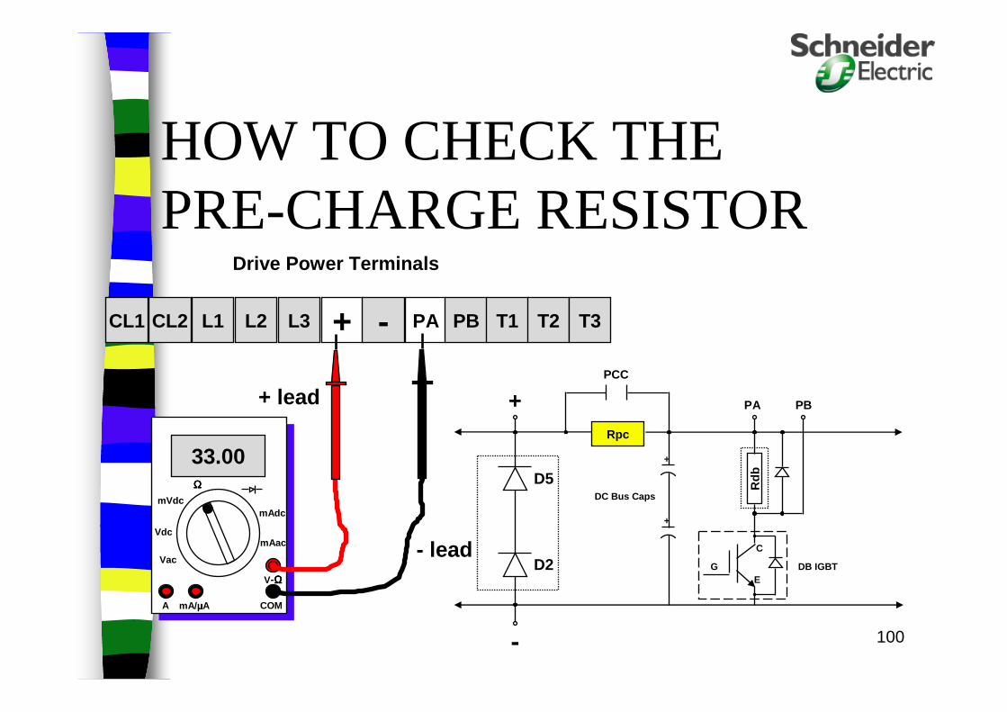
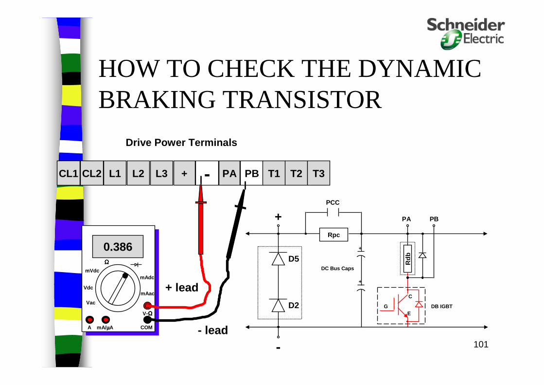
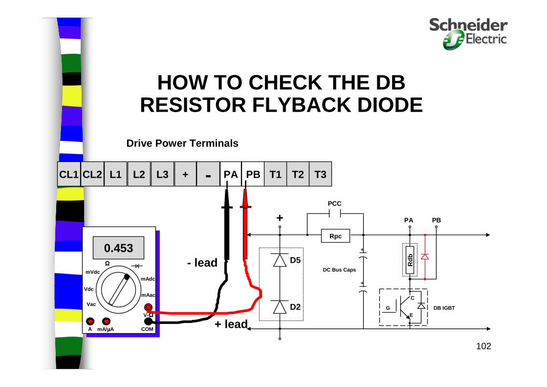
» Pre-charge resistor and DB transistor
» Inverter transistors and “free-wheel” diodes
» Snubber circuits
91
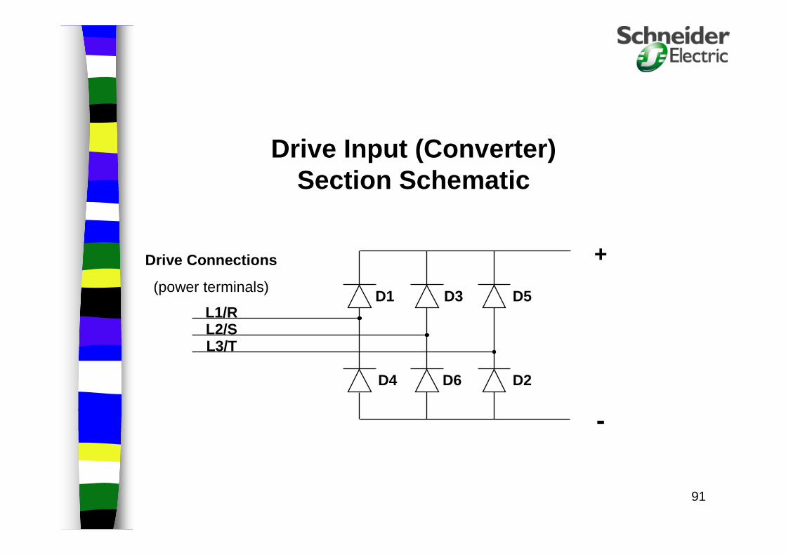
Drive Input (Converter) Section Schematic
Drive Connections
(power terminals)
+
-
L1/RL2/SL3/T
D1 D3 D5
D4 D6 D2

92
HOW TO CHECK THE CONVERTER DIODES
+ - PA PB T1 T2 T3L3L2L1CL2CL1
0.357
V-ΩΩΩΩ
COMmA/ µµµµAA
Vdc
Vac
mAac
mVdcmAdc
Checking D1 - Fwd Biased
Drive Power Terminals
+
-
L1/RL2/SL3/T
D1 D3 D5
D4 D6 D2
+ lead
- lead
ΩΩΩΩ
93
+ - PA PB T1 T2 T3L3L2L1CL2CL1
0.362
V-ΩΩΩΩ
COMmA/ µµµµAA
Vdc
Vac
mAac
mVdcmAdc
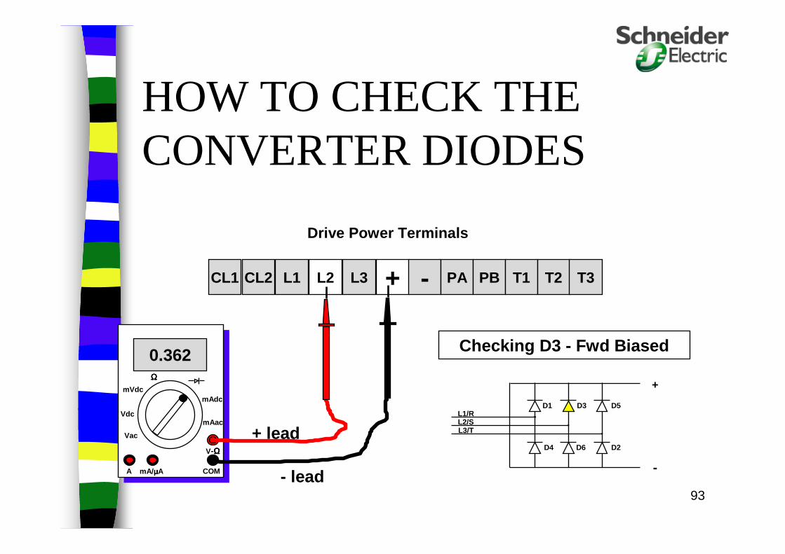
Checking D3 - Fwd Biased
Drive Power Terminals
+
-
L1/RL2/SL3/T
D1 D3 D5
D4 D6 D2
+ lead
- lead
HOW TO CHECK THE CONVERTER DIODES
ΩΩΩΩ
94
+ - PA PB T1 T2 T3L3L2L1CL2CL1
0.353
V-ΩΩΩΩ
COMmA/ µµµµAA
Vdc
Vac
mAac
mVdcmAdc
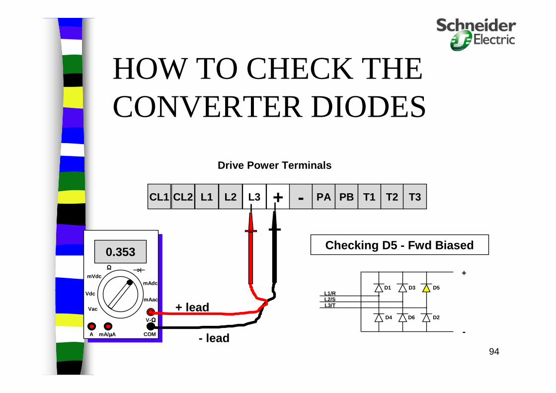
Checking D5 - Fwd Biased
Drive Power Terminals
+
-
L1/RL2/SL3/T
D1 D3 D5
D4 D6 D2
+ lead
- lead
HOW TO CHECK THE CONVERTER DIODES
ΩΩΩΩ

95
+ - PA PB T1 T2 T3L3L2L1CL2CL1
0.355
V-ΩΩΩΩ
COMmA/ µµµµAA
Vdc
Vac
mAac
mVdcmAdc
Checking D2 - Fwd Biased
Drive Power Terminals
+
-
L1/RL2/SL3/T
D1 D3 D5
D4 D6 D2
+ lead
- lead
HOW TO CHECK THE CONVERTER DIODES
ΩΩΩΩ

96
+ - PA PB T1 T2 T3L3L2L1CL2CL1
0.360
V-ΩΩΩΩ
COMmA/ µµµµAA
Vdc
Vac
mAac
mVdcmAdc
Checking D6 - Fwd Biased
Drive Power Terminals
+
-
L1/RL2/SL3/T
D1 D3 D5
D4 D6 D2
+ lead
- lead
HOW TO CHECK THE CONVERTER DIODES
ΩΩΩΩ

97
+ - PA PB T1 T2 T3L3L2L1CL2CL1
0.352
V-ΩΩΩΩ
COMmA/ µµµµAA
Vdc
Vac
mAac
mVdcmAdc
Checking D4 - Fwd Biased
Drive Power Terminals
+
-
L1/RL2/SL3/T
D1 D3 D5
D4 D6 D2
- lead
+ lead
HOW TO CHECK THE CONVERTER DIODES
ΩΩΩΩ
98
Drive DC Bus Section Schematic
L1/RL2/SL3/T
D1 D3
D4 D6
+
-
D5
D2
Rpc
PCC
Rdb
PA PB
G
C
EDB IGBT
+
+
DC Bus Caps

99
from Converter to Inverter
Drive DC Bus Section Schematic
(open circle) indicates conection on power terminal strip
+
-
D5
D2
Rpc
PCC
Rdb
PA PB
G
C
EDB IGBT
+
+
DC Bus Caps
100
HOW TO CHECK THE PRE-CHARGE RESISTOR
+ - PA PB T1 T2 T3L3L2L1CL2CL1
Drive Power Terminals
- lead
33.00
V-ΩΩΩΩ
COMmA/ µµµµAA
ΩΩΩΩ
Vdc
Vac
mAac
mVdcmAdc
+ lead +
-
D5
D2
Rpc
PCC
Rdb
PA PB
G
C
EDB IGBT
+
+
DC Bus Caps
101-
HOW TO CHECK THE DYNAMIC BRAKING TRANSISTOR
+ - PA PB T1 T2 T3L3L2L1CL2CL1
Drive Power Terminals
+ lead
0.386
V-ΩΩΩΩ
COMmA/ µµµµAA
ΩΩΩΩ
Vdc
Vac
mAac
mVdcmAdc
- lead
+
D5
D2
Rpc
PCC
Rdb
PA PB
G
C
EDB IGBT
+
+
DC Bus Caps
102
+
D5
D2
Rpc
PCC
Rdb
PA PB
DB IGBT
+
+
DC Bus Caps
G
C
E
HOW TO CHECK THE DB RESISTOR FLYBACK DIODE
+ - PA PB T1 T2 T3L3L2L1CL2CL1
0.453
V-ΩΩΩΩ
COMmA/ µµµµAA
ΩΩΩΩ
Vdc
Vac
mAac
mVdcmAdc
+ lead
- lead
Drive Power Terminals
103
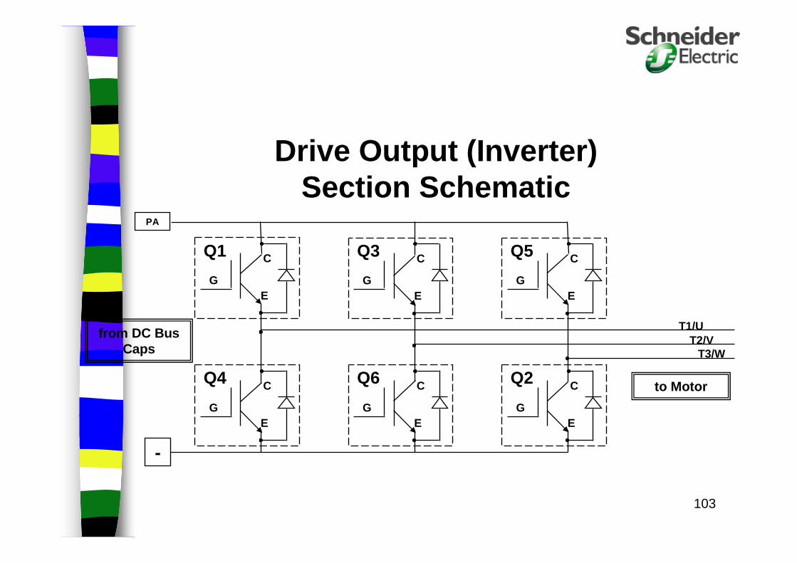
from DC Bus Caps
Drive Output (Inverter) Section Schematic
to Motor
T3/W
G
C
EG
C
EG
C
E
G
C
EG
C
EG
C
E
T1/UT2/V
PA
-
Q1 Q3 Q5
Q2Q6Q4
104
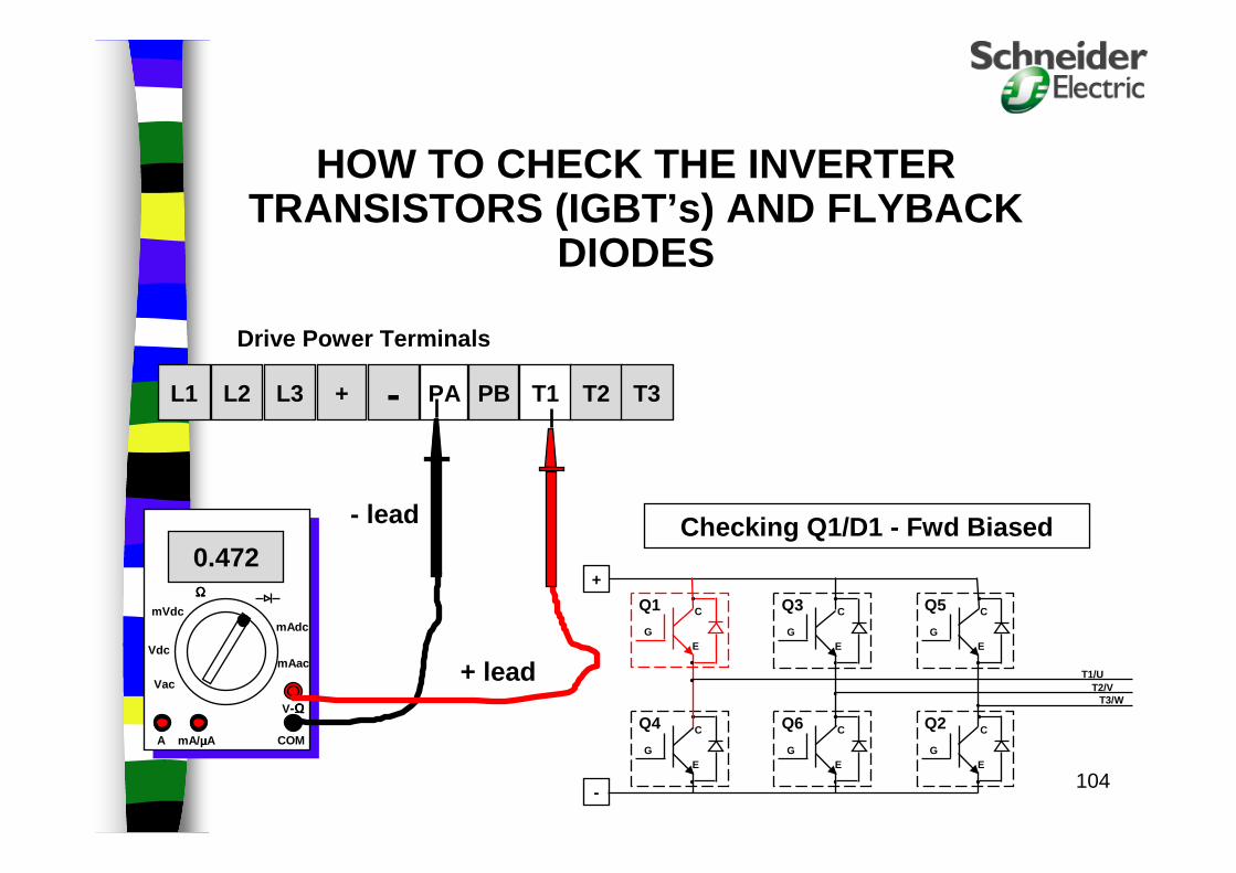
+ - PA PB T1 T2 T3L3L2L1
Drive Power Terminals
HOW TO CHECK THE INVERTER TRANSISTORS (IGBT’s) AND FLYBACK
DIODES
0.472
V-ΩΩΩΩ
COMmA/ µµµµAA
ΩΩΩΩ
Vdc
Vac
mAac
mVdcmAdc
+ lead
- lead
T3/W
G
C
EG
C
EG
C
E
G
C
EG
C
EG
C
E
T1/UT2/V
+
-
Q1 Q3 Q5
Q2Q6Q4
Checking Q1/D1 - Fwd Biased
105
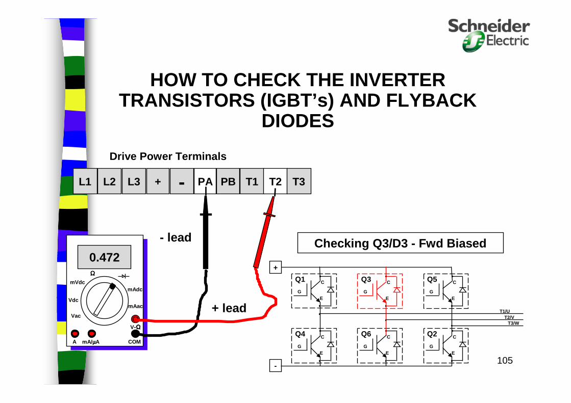
+ - PA PB T1 T2 T3L3L2L1
Drive Power Terminals
HOW TO CHECK THE INVERTER TRANSISTORS (IGBT’s) AND FLYBACK
DIODES
T3/W
G
C
EG
C
EG
C
E
G
C
EG
C
EG
C
E
T1/UT2/V
+
-
Q1 Q3 Q5
Q2Q6Q4
Checking Q3/D3 - Fwd Biased0.472
V-ΩΩΩΩ
COMmA/ µµµµAA
ΩΩΩΩ
Vdc
Vac
mAac
mVdcmAdc
+ lead
- lead

106
+ - PA PB T1 T2 T3L3L2L1
Drive Power Terminals
HOW TO CHECK THE INVERTER TRANSISTORS (IGBT’s) AND FLYBACK
DIODES
T3/W
G
C
EG
C
EG
C
E
G
C
EG
C
EG
C
E
T1/UT2/V
+
-
Q1 Q3 Q5
Q2Q6Q4
Checking Q5/D5 - Fwd Biased0.472
V-ΩΩΩΩ
COMmA/ µµµµAA
ΩΩΩΩ
Vdc
Vac
mAac
mVdcmAdc
+ lead
- lead

107
+ - PA PB T1 T2 T3L3L2L1
Drive Power Terminals
HOW TO CHECK THE INVERTER TRANSISTORS (IGBT’s) AND FLYBACK
DIODES
T3/W
G
C
EG
C
EG
C
E
G
C
EG
C
EG
C
E
T1/UT2/V
+
-
Q1 Q3 Q5
Q2Q6Q4
Checking Q2/D2 - Fwd Biased0.472
V-ΩΩΩΩ
COMmA/ µµµµAA
ΩΩΩΩ
Vdc
Vac
mAac
mVdcmAdc
+ lead
- lead
108
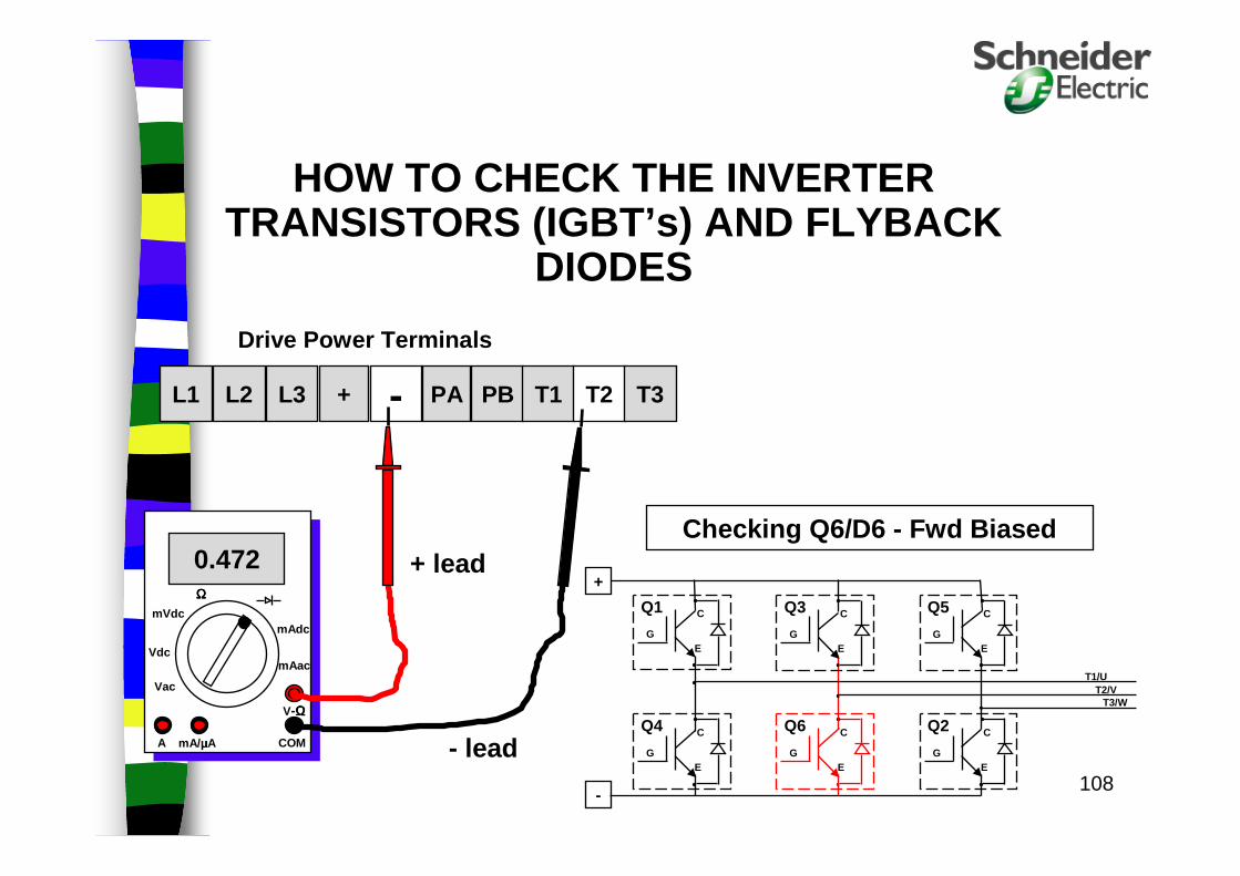
+ - PA PB T1 T2 T3L3L2L1
Drive Power Terminals
HOW TO CHECK THE INVERTER TRANSISTORS (IGBT’s) AND FLYBACK
DIODES
T3/W
G
C
EG
C
EG
C
E
G
C
EG
C
EG
C
E
T1/UT2/V
+
-
Q1 Q3 Q5
Q2Q6Q4
Checking Q6/D6 - Fwd Biased0.472
V-ΩΩΩΩ
COMmA/ µµµµAA
ΩΩΩΩ
Vdc
Vac
mAac
mVdcmAdc
+ lead
- lead

109
+ - PA PB T1 T2 T3L3L2L1
Drive Power Terminals
HOW TO CHECK THE INVERTER TRANSISTORS (IGBT’s) AND FLYBACK
DIODES
T3/W
G
C
E
G
C
EG
C
EG
C
E
T1/UT2/V
+
-
Q1 Q3 Q5
Q2
G
C
E
Q6
G
C
E
Q4
Checking Q4/D4 - Fwd Biased0.472
V-ΩΩΩΩ
COMmA/ µµµµAA
ΩΩΩΩ
Vdc
Vac
mAac
mVdcmAdc
+ lead
- lead

110
Drive Input Measurements
AC Mains voltage
– Use true RMS meter for accurate readings
– Measure and verify voltage balance between L1&L2, L1&L3, L2&L3; less than 5% is good
– Verify amplitude is within range(460V +/-15%)
AC Mains current
– Must use true RMS meter with current probe
– Check for balanced currents in each phase
– Imbalance indicates poor connection or bad input rectifier section
Full Power Checkout

111
DC Bus Measurement
Any meter capable of measuring up to 1000Vdc should read accurately
Verify that level is 1.4x AC RMS level of the input
If input rectifier bridge is suspect, voltage ripple may be checked with an oscilloscope
Check that voltage is below 50V before touching any components or performing ohmmeter testing
Full Power Checkout
112
Drive Output Measurements
Voltage measurement
– Accurate voltage measurements can only be had using an Harmonic signal analyzer or a bandwidth limited true RMS meter; an averaging meter gets close
– Typical true RMS meter will tend to read high; balanced voltagesare the key
Current measurement
– Any type meter and a current probe should give accurate output current reading; check balance of output currentswith motor connected and running. Verify currents are < drive/motor rating.
– beware of low frequency limitation of probe
Full Power Checkout

113
Control Circuit Measurement
Includes: Power supplies, logic inputs/outputs, analog inputs/outputs, feedback measurements, logic states
All control circuits should be able to be accurately measured with any type of multi-meter
This is also where an oscilloscope can be used most effectively
Full Power Checkout

114
SIGNALS NEEDED FOR DRIVE TO RUN
Logic Input 1– This input must be closed (active high) to enable
the drive. also known as the “run permissive”input. input makes the drive “ready” to run. Tie LI1 to + power supply (ATV11/+15VDC)
Auto-start contact – This input gives the “start running” command to
the drive. this input must also be closed (active high) to start the drive.
Speed reference signal (ANALOG INPUT 1 and/or 2)– Drive needs to be told how fast to run. signal
comes from ucm or some other source. typically a 0-10v, 2-10v, or 4-20ma signal is used. (Or set Low speed to 20 hz)

AccuSineHarmonics Solution
and/orPower Correction System

116
More Advanced Training
If after this course you are interested in more advanced training, please let us know.
We have in depth Hands-on VFD and PLC training done by our Training Department.

117
Thank You for YOUR Time!

118
Thank You for YOUR Time!