in marseille having a clear span of 76 - · pdf filespace frame structure of parc chanot...
TRANSCRIPT

SPACE FRAME STRUCTURE OF PARC CHANOT EXHIBITI ON HALL IN MARSEILLE HAVING A CLEAR SPAN OF 76 M.
J.Y. Morineau, T. Kaya, Ö. Özalp, S. Kılınç Uskon-Europe, 10/12, allée des Champs-Elysées, 91042 – EVRY, (France) , [email protected] Uskon Space Frame Systems Construction Inc. Barış Mah. Koşuyolu Cad. No:82 Gebze, Kocaeli, Turkey , [email protected] , [email protected] , [email protected] 1. ABSTRACT : This document describes design, production and erection works for The Space Frame of Parc Chanot Exhibition Hall having a clear span of 76 meters in Marseille, France. The purpose of this project was to replace the old Hall 1 of Parc Chanot Exhibition Center in City of Marseille, by a new and larger hall. The development of the project was confided by SAFIM, the owner, to the architect Eric Castaldi, with main target to design a 6,000 m2 building with a minimum of supports. Another requirement was to have a maximum of hanging points to be used during exhibitions for signs, advertisings and lighting.
Figure 1. Architectural Plan of the Building for a Convention with separator wall
2. ARCHITECTURAL DESIGN Eric Castaldi had in mind to use a space frame to build the roof, since this technology offers the right answers to these inquiries: capacity of large-span roofs, many nodes that can be used as hanging points, and also possibility of choosing support points anywhere, aesthetic of the joints, large choice of geometries, etc… The tender drawings and preliminary calculations have been established by local companies. The proposed space frame was based on a triangular modulation, typical module size was about 3m in plan and 3m depth. The analysis of this design showed that the structure was very flexible, and had to be cambered in order to get a reasonable deflection under dead loads. Also, the combination of loads was giving very high axial forces in the members.

Figure 2 : The First Design Concept of The Structure
As a result, we considered that this design was very expensive, and not optimised for such a construction. We therefore decided to propose an alternate solution. Since this project was also requiring conventional steel structures, continuous presence on job site and rigorous organization in order to complete the project on time, we decided to make a partnership with Castel&Fromaget.
150
5231
5231
Figure 3. Layout Plan for The Bottom Chord Level of The Space Frame

In the final design, The space frame modulation was selected as 4.243 m x 4.243 m. with an angle of 45o in plan. The height of the space frame varies from 3.00 m to 4.80 m. The clear span of the space frame is 75.6 m. The length of the longer side of the space frame is 84.60 m. Total area of the system is 6396 m2 in plan. The space frame is supported by 22 numbers of the steel columns on the perimeter.
Figure 4 : Architectural Elevations
The structure was designed, and produced in Turkey by Uskon. The system was divided into 3 main production and assembly parts. The first and second parts are erected on the ground separately. Following of the completion of all equipments in the space frame on the ground, they were lifted by cranes onto their original positions. Two separate lifted parts are connected to each other by the third part on the air. The assembly works was one of the design phases. 3. STRUCTURAL DESIGN Modulation of the project was realized as 4.243 x 4.243 m. in structural design. Since the layout of the modulation is placed as 45o in plane, secondary modulation has been obtained as 3.0 m x 3.0 m. as shown in Figure 5. Because of the deflection problems, the top-chord layer was used as sloped to increase the height of space frame on the middle part of the span. A geometrical chamber of 15 cm. applied on the bottom chord level to avoid visual effect of large vertical displacements. On the perimeter, there were 22 numbers of “I“ shaped steel columns. Since there were large doors on the perimeter having a width of 30 m, no supports could have been used on these parts. Althought the structural span is 75.6 m, depending on the non-orthogonal modulation, working span is much more than this shortest distances of 75.6 m. between the sides. Some of the steel columns on the perimeter were connected to each other with some diagonal bracing members for lateral stability. These members can take not only tension but also compression loads. Because of the entrance and exit doors, some stability members were cancelled on the perimeter.
3.000 3.000 3.000
3.000
3.000
3.000
4.243
4.243
BOTTOM CHORD
TOP CHORD
DIAGONAL
Figure 5 : Modulation of The Space Frame Figure 6 : Columns and Bracing Members

The minimum height of the space frame on the sides is 3.00 m. The height reaches to 4.80 m. on the middle part raising from the four sides on the perimeter as shown in Figure 6. The length of the members in the space frame varies in a range of 3.00 and 6.30 m. Because of the large span and deflections caused by this large span, a small geometrical chamber used to obtain sloped bottom chord level to satisfy visual requirements for deflections. There is 15 cm. difference between the lowest and the highest point of the bottom chord for unloaded condition. This difference covers the deflection due to the total dead load on the structure. For permanent loads, no deflection can be seen on the space frame. Because of the geometrical chamber of 15 cm, differences between bottom chord level on the sides and the highest point of the space frame on top chord is 4.95 m. Depending on these dimensions, the slope of the top chord is obtained as 5%. This slope helps to purlins to connect them directly onto the nodes without using vertical purlin stools.
Figure 7 : The Sections of the Space Frame and Variation of the Height 4. DESIGN CALCULATIONS : Design calculations were prepared as per Eurocode 1 and Eurocode 3 using Load and Resistance Factor Design Method. Additionally, since the structure was built in France, some different coefficients were taken than French Codes for inconvenient conditions. Similarly, bearing capacities for bolts assumed in design calculations were reduced depending on the regulations given in French Code. In all phases of structural design, always the most inconvenient conditions have been taken into account comparing Eurocode and French Codes. The loading criteria in the project are as follows. - Space Frame Self Load : 34.6 kg/m2 - Cladding + Purlins : 31.0 kg/m2 - Snow Load : 35.0 kg/m2 - Exceptional Snow Load : 80.0 kg/m2 - Wind Load : 82.5 kg/m2
- Air-condition Load : 150 kg/düğüm - Service Load : 25.0 kg/m2 - Separator Wall (3 Lines) : 400 kg/m - Temperature Differences : ∆t = ± 15°C
Figure 8 : Structural Model of the Building In design calculations, 18 no’s of different loading cases were combined each other in 263 no’s of different loading combinations. The model of the space frame was analyzed using the software of SAP2000 v7.44 as a whole with substructure. The results are checked in France using ROBOT v 16.1

As a result of design calculations some information and results with extreme values are given below. Area of Space Frame = 6395.76 m2 Number of Members = 3011 no’s Number of Nodes = 778 no’s Number of Supports = 22 adet Number of Purlins = 602 adet Number of Purlin Stools = 390 adet Span of the Space Frame = 75.60 m. Space frame Self Weight = 34.6 kg/m2 Minimum Diameter of Pipes : D = 76.1 mm, t = 3.65 mm Maximum Diameter of Pipes : D = 273.0 mm, t = 8.00 mm Minimum Bolt Diameter : M16 - 10.9 Maximum Bolt Diameter : M64 - 10.9 Minimum Node Diameter : D = φ 130 mm Maximum Node Diameter : D = φ 330 mm Maximum Tension Load on the Members : N = 1163.77 KN Maximum Compression Load on the Members : N = 1181.82 KN Minimum Vertical Reaction : Rz = - 336.76 KN Maximum Vertical Reaction : Rz = 1699.53 KN Maximum Horizontal Reaction : Rx = 683.13 KN Maximum Lateral Displacement in X Direction : δx = 3.25 cm Maximum Lateral Displacement in Y Direction : δy = 3.55 cm Minimum Vertical Displacement (-) ( downward ) : δz = 26.07 cm Maximum Vertical Displacement (+) ( upward ) : δz = 2.57 cm In the results given above, tension or compression values and support reactions include load factors. The given displacements do not include load factors. 5. SUPPORT DETAILS 22 no’s of supports existing on the Space Frame have been connected to the substructure on the steel columns to make the whole system to work together. To have flexibility for temporary application during erection process, 4 additional bolt connections having larger diameter were used on the connection plates. The connection details for supports on steel columns are given in Figure 9.
8
FA
2
Figure 9 : Support and Connection Details

There is another holed plate under the support in an equal dimensions with the ones on the column. After the erection phase was completed, top and bottom plates were welded to each other on site. 6. CLADDING DETAILS Membrane type of cladding has been used in the project. The rainwater has been taken by drainage system on the sides. For this purpose, a slope has been used on the last modulation to take the collected water. On the sides, I shaped vertical purlins have been design to form the outer facade. Some additional accessory members have been used to transmit horizontal wind loads from the sides when there is no top chord node in the direction of the vertical purlins to apply all loads from by the nodes.
Figure 10 : Details of Side Cladding 7. ASSEMMBLY WORKS OF THE SPACE FRAME When preparing assembly project, the main purpose was to minimize the cost for erection and to be far from the risks of erecting on the air as much as possible. While preparing the time schedule of the whole project, it was assumed that, all service loads like air-condition ducts, fire protection walls, other required equipment in the space frame would be assembled on the ground. The period and the sequence of the whole job were planned according to this assumption. With this purpose, the space frame was divided into 3 separate assembly zones as shown in Figure 11. Two main parts, Zone 1 and Zone 2, have been assembled on the ground separately. After all accessories in the space frame have been installed on the ground by the other teams, these two main triangular space frame parts have been lifted onto their original places on the columns separately by the cranes as shown in Figure 12. In the third phase, the gap between these two main triangular space frame has been completed on the air by using scaffoldings.
X
X
X
X
X
X
g
90
72
x=69°
x=71°
Figure 11 : Assembly Zones Figure 12 : Lifting Points of Zone1
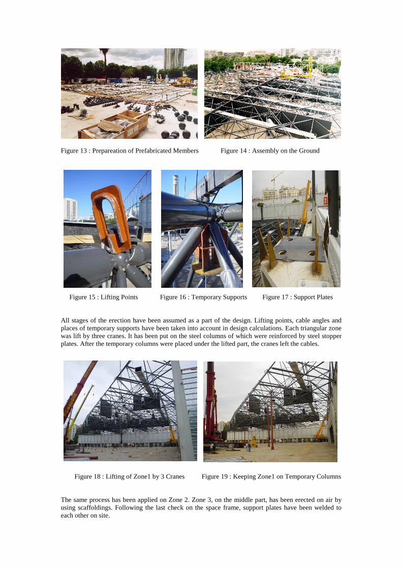
Figure 13 : Prepareation of Prefabricated Members Figure 14 : Assembly on the Ground
Figure 15 : Lifting Points Figure 16 : Temporary Supports Figure 17 : Support Plates All stages of the erection have been assumed as a part of the design. Lifting points, cable angles and places of temporary supports have been taken into account in design calculations. Each triangular zone was lift by three cranes. It has been put on the steel columns of which were reinforced by steel stopper plates. After the temporary columns were placed under the lifted part, the cranes left the cables.
Figure 18 : Lifting of Zone1 by 3 Cranes Figure 19 : Keeping Zone1 on Temporary Columns The same process has been applied on Zone 2. Zone 3, on the middle part, has been erected on air by using scaffoldings. Following the last check on the space frame, support plates have been welded to each other on site.

Figure 20 : Lifting of Zone2 by 3 Cranes Figure 21 : Finalizing of the Assembly Works 8 – CONCLUSION : The Parc Chanot Exhibition and Convention Hall were put into service first on 19th September 2003 for the exhibition of “ Foire Internationale de Marseille, 2003 ”
Figure 22 : General View of The Building Before Cladding Works