in quartz and feldspars ouro preto, brasil.* · in quartz and feldspars hens reurvyc, escola...
TRANSCRIPT

THE AMERICAN MINERAIOGIST, VOL.46, JULY AUGUST, 1961
ARTIFICIAL AND NATURAL PHOTOELASTIC EFFECTSIN QUARTZ AND FELDSPARS
HeNs Reurvyc, Escola I{acional d.e Minas e Metallurgia,Ouro Preto, Brasil.*
Assrnacr
Optical disturbances occur in quartz and feldspars around stress centers as caused byimpact from carborundum grains during preparation of thin sections. This photoelasticphenomenon is described and compared with the optical disturbance observed aroundstress centers produced in various substances such as cellophane paper, photographic film,plexiglass and common glass. The interference figures observed with crossed nicols showthat the stress fields have cylindrical or spherical symmetry, the stress decreasing rapidlywith distance from the centers. Similar photoelastic efiects are seen around inclusions inquartz and feldspars, showing that inclusions are sometimes surrounded by stress fieldswith maximum compressive stress parallel to the radius. Some piezo-optical properties ofquartz and potash feldspar are measured qualitatively in order to interpret the characterof the stress fields. For these minerals the deformation of the indicatrix under unidirectedcompressive stress is similar to the deformation of the strain ellipsoid in the sense that theindicatrix becomes elongated, relatively, in directions normal to the stress. Plexiglass be-haves in an opposite manner, its indicatrix being relatively elongated parallel to the direc-tion of compressive stress.
CBNTnnS OF PHoToELASTIC DISTURBANcES IN QUARTZ AND
Ferospans AS PRoDUCED DuRTNG PnnplnarroN
OT THIN SBcrroNs
Quartz grains cut quasi-normal to the optic axis often show a faintgating texture when observed with crossed nicols at moderate magnifi-cation. At the first glance the texture usually appears as a set of some-what irregular extinction bands making about a 45o angle with the vibra-tion directions of the nicols, crossed by a quasi-normal set of irregularbright bands. Being invisible when the quartz grain is in position of ex-tinction, the grating texture shows up at only a few degrees deviationfrom this position and remains visible at any angular deviation from ex-tinction of the quattz grain, provided that the optic axis is quasi-parallel to the microscope axis. Rotation of the thin section makes thedark bands and the complementary bright ones alternate between thefirst-third and the second-fourth quadrants, bisecting symmetricallythe vibration directions of the nicols.
This apparently common texture seems so far to have failed to arousesuficient interest among petrographers and mineralogists to motivatepublication. During thin section work on gneisses from Brazil the writerstudied the feature in some detail and found that it represents an inter-esting example of photoelasticity in minerals, a phenomemon hardly dis-
* Present address: Department of Geophysical Sciences, University of Chicago.
934
PHOTODLASTIC EFFECTS IN QUARTZ AND FELDSPARS
cussed in geological literature. Although recognized as chiefly caused bystresses produced during preparation of the thin sections, the feature mayserve as a model for the optical disturbances induced by stresses aroundinclusions and some lattice defects in minerals.
The feature appeared most distinctly at moderate magnification, e.g.between 50 and 200X, the dark and bright bands generally being too finefor less magnification, whereas higher power (say 500X) made the patternvery diffuse.
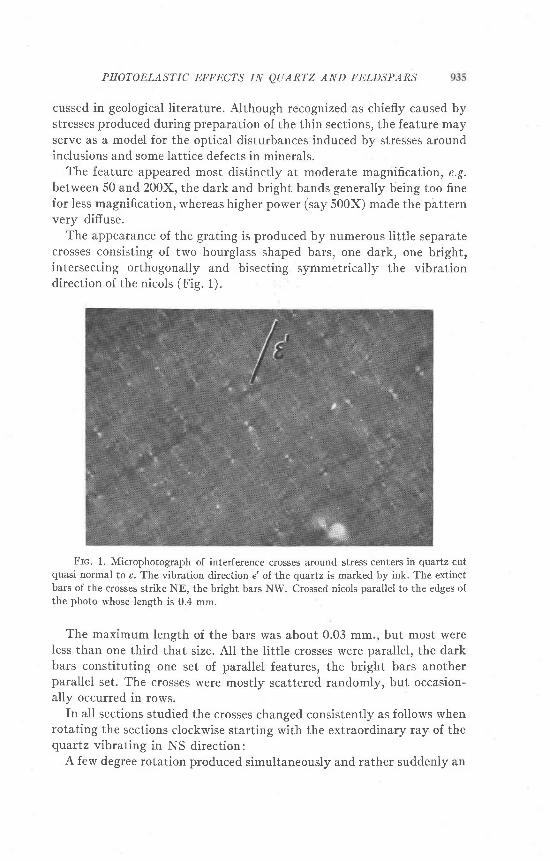
The appearance of the grating is produced by numerous little separatecrosses consisting of two hourglass shaped bars, one dark, one bright,intersecting orthogonally and bisecting symmetrically the vibrationdirection of the nicols (Fig. 1). :
Frc. 1. Microphotograph of interference crosses around stress centers in quartz cutquasi normal to c. The vibration direction e'of the quartz is marked by ink. The extinctbars of the crosses strike NE, the bright bars NW. Crossed nicols parallei to the edges ofthe photo whose length is 0.4 mm.
The maximum length of the bars was about 0.03 mm., but most wereless than one third that size. AII the little crosses were parallel, the darkbars constituting one set of parallel features, the bright bars anotherparallel set. The crosses were mostly scattered randomly, but occasion-ally occurred in rows.
In all sections studied the crosses changed consistently as follows whenrotating the sections clockwise starting with the extraordinary ray of thequartz vibrating in NS direction:
A few degree rotation produced simultaneously and rather suddenly an

936 HANS RAMBERG
appearance of numerous crosses with dark bars bisecting at about 45o thefirst-third quadrants, and bright bars or elongate regions bisecting thesecond-fourth quadrants, the vibration directions of the nicols beingthe reference coordinates. This pattern remained immobile, except forminor variations in the brightness and darkness of the bars, until e'-the vibration direction of the extraordinary ray-is lined up with theEW direction when the uniform extinction is interrupted only by hardlyvisible small areas of light in the regions where the largest crosses hadbeen.
A few degree further rotation caused a sudden reappearance of thecrosses, but in a reversed position oiz. with the dark bars bisecting thesecond-fourth quadrants and the bright ones in the first-third quad-rants. The crosses remained in this position during the next 90o rotationof the quartz, i.e, until uniform extinction when e' became parallel to theNS direction after 180? rotation from the starting point.
Checks with f tr quartz plate showed that, within the circular regionsswept out by the bars of the little crosses, the intersection of the indi-catrix with the plane of the thin section was deformed (or rotated) inthe manner shown in Fig. 4.
The variation of the brightness and darkness of the bars indicated thatin general the magnitude of indicatrix deformation increased toward thecenters.
This indicates a photoelastic effect created by local concentric distri-bution of anisotropic stress in the quartz lattice, the intensity of thestress increasing toward the center.
Before discussing some tests made to check this assumption, we shalldescribe the optical disturbances around the few centers of exceptionallystrong deformation inasmuch as these showed details not visible in thelitt le crosses.
When the qlrartz grains were in the position of extinction, some inter-ference light passed through a few scattered small regions. In these re-gions the extinction was complete only along the arms of an orthogonalcross parallel to the vibration directions of the nicols, leaving a sector offaint l ight in each quadrant.
Clockwise rotation from a position e'l l NS made the bars of the crossesbend, the north end of the vertical bar and the east end of the horizontalbar bending into the first quadrant at the same time as the south end ofthe vertical bar and the west end of the horizontal bar bent into the thirdquadrant. The cross thus changed into a figure 8 pattern, the longest axisof which bisected symmetrically the first-third quadrants while the sec-tion was rotated until e' became parallel to EW. During this rotation,however, the long axis of the figure 8 "isogyre" changed, its length con-

PHOTOELASTIC EFFECTS IN QUARTZ AND FELDSPARS 937
tinuousiy decreasing during the first 45o rotation of the section and in-creasing again until e' was parallel to EW, at which point the figure 8 pat-tern opened up to an orthogonal cross. Further clockwise rotation pro-duced a figure 8 pattern in the second-fourth quadrants. A similar inter-ference pattern occurs in glass, Fig. 2.
Insertion of a ] tr quartz plate with e vibrating in the first quadrantgave additive interference color within the "eyes" of the figure 8 when itfell in the second-fourth quadrants, arrd subtractive color when thefigure 8 feil in the first-third quadrants. Outside the figure 8 pattern,but close to its center, additive interference color stronger than in therest of the qtartz grain occurred when the figure 8 occupied the first-third quadrants. In these same regions outside the figure 8, substractive
Frc. 2. Microphotograph of interference figures in stress fields caused by little grainsof carborundum pressed between cover glass and objective glass made double refractingby application of compressive stress in direction o. The vibration direction of the high-index ray is marked 7r. crossed nicols parallel to edges of photos. Note horv the centralfigure-8 pattern changes with varying angle between 7' and the nicols. Length of photos0.2 mm.

938 HANS RAMBERG
interference color lower than the rest of the crystal occurred when the
figure occupied the second-fourth quadrants.
When the bulk of the crystal was in the position of extinction such that
a dark cross with four small sectors of light occurred at points of excep-
tional strong optical disturbance, the | \ quattz plate gave always addi-
tive color for the light sectors in the second and fourth quadrants, and
substractive color in the first and third quadrants.
These observations on the regions of strong disturbances verified the
notion that the qtrartz indicatrix was significantly deformed within more
or less circular (spherical, cylindrical?) regions, the general pattern of
deformation being as shown in Fig. 4'The figure 8 extinction pattern may perhaps not seem an obvious con-
sequence of such radial distribution of indicatrix deformation, but a closer
study will reveal that a pattern of this kind is exactly what should be ex-
pected if the indicatrix is deformed in a field of anisotropic stress with
spherical or cyiindrical symmetry.A grating texture similar to that described from the qtattz was some-
time seen in plagioclase and potash feldspar. In the feldspars, however,
the pattern was rarely developed as clearly and as symmetrically as in
the quartz. The bright and dark elongate regions were rather difiuse,
they were not always quasi-normal to one another but appeared some-
what controlled by the tricline structure of the feldspars, and often one
set of linear regions showed up much better than the other'
In quartz as well as in feldspars the feature here described would be-
come less and less visible the more the optic axis deviated from the
microscope axis. For large anguiar deviation of these axes the optical dis-
turbances could only be seen when the crystals in bulk were close to the
position of extinction.
ExponrupxrAr TESTS
It is generally true that transparent solids show photoelastic efiects in
the sense that their indices of refraction vary with magnitude and geome-
try of the stresses applied, the piezo optical coeffi.cient being the measure
of the relationship between stress and indices of refraction. An excellent
discussion of this phenomenon is found in Nye (1957). Unfortunately
nothing seems to be known with reference to the piezo optical coefficient
of quartz and leldspar.As an interpretation of the described optical disturbances to the first
approximation does not require a quantitative knowledge of piezo
optical coeffcient (the sense of the change of double refraction with
stress is sufficient) the experiments were limited to qualitative stress tests
on small polished samples of. quartz and feldspars.

PHOTOELASTIC EFFECTS IN QUARTZ AND FELDSPARS 939
Rectangular plates some 2-4 mm. thick were cut and polished normalto the c-axis of quartz, and other plates of similar thickness were cutparallel to this axis. The plates were subjected to compressive stress indirection parallel and normal to the c-axis in the plane of the plates, andthe variation of the double refraction noted in the microscope by help ofcompensatin g quaftz wedges. ft was found that in all cases the double re-fraction changed in such a fashion as to show that the indicatrix was de-formed in a manner similar to the elastic strain ellipsoid, i.e. dimensionsof the indicatrix which were parallel to the applied compressive stressdecreased relative to dimensions normal to the stress.* when compressivestress was applied parallel to c on the plates cut parallel to this axis thedouble refraction [1,7,:6t-rt decreasedl when stress was applied normalto c on the same plates the double refraction increased. Stress appliednormal to the trigonal axis on the plate cut normal to this axis made theplate distinctly double refracting with the smaller axis of the deformedindicatrix parallel to the stress. rn the latter case the indicatrix became atriaxial ellipsoid.
The significance of these tests is to show that for quartz the photo-elastic distortion (i.e. the deformation of the indicatrix under stress) issimilar to the deformation of the elastic strain ellipsoid. This was neces-sary to check inasmuch as there exist solids whose indicatrix distortionunder stress is opposite to the deformation of the strain ellipsoid. rn otherwords the indicatrix becomes elongated (relatively) in the direction ofthe highest compressive stress. rt is, however, possible that all axes of theindicatrix increased under uniaxial compression, but to different degree.Potassium chloride is an example of a crystalline solid with this character(Nye, 1957, p. 255); plexiglass, which was used in the model tests below,is an example on an amorphous substance with such photoelastic char-acter.
Because of low symmetry the number of piezo optical coefficientsnecessary to describe fully the photoelastic character of feldspars isgreat-36 different coefficients for triclinic feldspars and 20 for mono-clinic (Nye 1957 , p.250) as compared with 8 for low qtrartz. No attemptwas made to determine fully the photoelastic character of feldspar, but afew tests were made on cleavage fragments parallel to (001) and parallelto (010) of potash feldspars (adularia and orthoclase of the type char-acteristic of charnockite rocks).
When the basal cleavage fragments were compressed in directionparallel to the o- and the 6-axes respectively, and the change in double
* The experimental tests did not give information about the absolute variation of theindices of refractionl it may well be, for example, that all three indices increased with in-creasing uniaxial compressive,stress.
940 HANS RAMBERG
refraction observed on basal cleavage flakes, it was found that the in-
dicatrix cross section was relatively compressed in direction of the stress.
Cleavage flakes parallel to (010) showed a similar deformation of in-
dicatrix cross section , i.e. the indicatrix was elongated normal to the com-
pressive stress when applied parallel to a as well as when applied normal
to (001). It appeared, however, that the effect was sensibly less when
stress was applied normal to (001) than when applied parallel to a.
It appears then, at least for stress applied in the direction noted above,
that adularia and orthoclase behave photoelastically similar to quattz
(but opposite to plexiglass) in the sense that the distortion of the indi-
catrix under stress is qualitatively similar to the distortion of the strain
ellipsoid under the same stress.In light of these tests of the photoelastic character of qtartz and feld-
spars, it follows that the concentric optical disturbances as described
from thin sections are caused by a spherical or cylindrical stress field with
the highest principal stress parallel to the radius, a stress distribution to
be expected if caused by a nucleus of high pressure'
To obtain more detailed information about the photoelastic effect
of a spherical or cylindrical stress field in an optically anisotropic medium
such fields were artifically produced in various transparent solids which
either possessed permanent double refraction (cellophane paper' photo-
graphic fiIm, plexiglass), or were made double refracting by application
of directed uniform stress (common glass), superimposed on the spherical
or cylindrical stress field.fn sheet-shaped samples of these substances smaller or larger regions
of quasi-concentrically distributed stress were developed by pressure
from a pointed instrument (on cellophane paper' photographic film,
plexiglass), by hitting the surface with a pointed metal tool (glass), or by
drilling tiny holes in which plugs of lead were stampted (plexiglass, fiIm) '
The points of pressure or impact, and the plugs of lead acted as centers
about which the concentric stress is distributed with the largest prin-
cipal stress parallel to the radius and decreasing rapidly with distance
from the center as given by equations (1) to (3) below.
This stress pattern simulates the condition to be expected for example
around mineral inclusions with small compressibility enclosed in more
compressible mineral if exposed to increasing external pressure. If an in-
clusion is more compressible than its host, release of confining rock pres-
sure (e.g. elevation of a rock complex from depth due to surface erosion)
may result in the same kind of stress pattern around the inclusion. Vari-
able temperature combined with unlike thermal expansion of inclusion
and host could also give stress distribution of this type. Similar stress dis-

PHOTOELASTIC EFFECTS IN QAARTZ AND FELDSPARS 94I
tribution may moreover result from an inclusion growing in a mineral,the inclusion executing a certain "force of crystallization.,,
In some instances the stress pattern was reversed during the tests insuch a fashion that the largest principal compressive stress was madenormal to the radius. This was achieved by subjecting a circular sheet ofplexiglass with a small open hole to planar compressive stress acting inradial direction around the circumference. rn the vicinity of the hole,maximum principal compressive stress is then normal to the radius, anddecreases with increasing distance from the hole.
This situation would serve as a model for the stress distribution aroundan inclusion whose compressibility is greater than that of the host min-eral provided the mineral is exposed to increasing rock pressure. If aninclusion is less compressible than its host, release of rock pressure maycause a stress distribution as here mentioned. Unmixing of alkali feldsparshould create a similar stress pattern around the albite lamellae inasmuchas the unit cell of albite is considerably less (about 10/6 by volume,Laves, 1952,p.551) than that of microc l ine.
All the thus prepared samples showed at crossed nicols under themicroscope interference pattern essentially similar to that around thedescribed disturbances in quartz and feldspars. The pertinent featurecommon to the disturbed little regions in all samples was an area of ex-tinction in each of two diametrically opposite quadrants of the crossednicols and areas of brightness in the two other quadrants. The fields ofextinction and brightness would alternate among the quadrants upon ro-tation of the microscope stage. Indeed, in common glass, texture indis-tinguishable from that in quartz was produced simply by grinding asheet of glass as if it were a mineral section, applying canada balsam andcover glass. when this section was put under homogeneous plane stress,such as to give it a faint double refraction, and observed under crossednicols its grating structure of optical crosses Iooked identical to that ofqtrarrz. During grinding, impacts of the carborundum grains on the sur-face of the quartz creates the same kind of stress centers as they do onthe ground glass.
The most ideally symmetrically interference figures were developedaround plugged holes in the plexiglass (Fig.3). This substance was there-fore best suited for a detailed study. One must note, however, that plexi-glass (at least the piece that was used in these experiments) has photo-elastic properties of opposite character to qu.artz, feldspars and the othersubstances (giass, cellophane paper, film) tested. Independent stresschecks on plexiglass showed that its indicatrix becomes relatively elon-gated in the direction of maximum compressive stress.

942 HANS RAMBERG
The deformation of the indicatrix is essentiaily determined by the
difference between radial and tangential stresses around the stress center,
and by the orientation of the stress ellipsoid relative to the original
indicatrix. The difference of radial and tangential stresses o,-o6, abotrt
the cylindrical hole (pressure:0) varies with distance r from the center
thus
1)2a2b2 P"
o r - o 0 : j o r : - - " i
where o is radius of the hole, D radius of the disk and P" pressure on the
circumference of the disk. As a and b are constant for a given test disk it
is seen that the stress difierence decreases rapidly with distance from
center.For a plugged hole in which pressure is Pr and pressure on the circum-
ference on the disk is zero, the stress difference at distance r fuom centerIS
2o2b2 Pno t - 6 0 : J o 2 : - ; ^ - - - '
b 2 - a 2 1 2
(see Jaeger 1956, p. 126). It the disk is large relative to the hole the equa-
tion reduces top
L o 1 : l s z : 'y z
P ,t " r : - 2 o ' * '
Fig. 3 shows a sequence of microphotos of the interference figure
around a plugged hole in plexiglass.In analyzing the interference figure of the plexiglass let us for sim-
plicity assume that the stress is distributed with cylindrical symmetryaround the plugged cylindrical hole whose axis is normal to the surface
of the sheet. The conditions that the radial compressive stress decreases
with distance from the center, and that the relative elongation of the
indicatrix increases with increasing intensity of stress difference, i.e. dif-
ference between radial and tangential stresses, result in the following pat-
tern of indicatrix deformation: Along the radial direction from the stress
center which is parallel to the long axis of the indicatrix in the undis-
turbed plexiglass, the elongation of the indicatrix simply increases as the
center is approached. Along the radial direction which is parallel to the
small axis of the undisturbed indicatrix, the elongation of the indicatrix
decreases as one approaches the stress center unti l at a certain distance
the indicatrix cross section becomes circular. At this distance the stressis exactly sufficient to neutralize the optical anisotropy of the plexiglass.
This happens at two diametrically opposite points about the stress

PHOTOELASTIC EFFECTS IN QUARTZ AND FELDSPARS 943
Frc. 3. Microphotographs of interference figures in stress field around plugged hole ina plate of plexiglass. The lines in upper middle and upper right sides of the photos give thevibration direction of the low-index ray in the plexiglass, and indicate the angular deviationof the sample from the crossed nicols which are parallel to the edges of the photos. Diame-ters of photos 1.3 mm.
center. These points are extinct at any angular position of the sheetrelative to the nicol directions, and the figure S-shaped "isogyre" mustalways pass through these points.
fn the region between the two "isotropic points" and the center ofstress the indicatrix becomes increasingly elongated in direction parallelto the radius as the center of stress is approached.
For quartz and orthoclase cut quasi-normal to the optic axis, forcellophane paper and photographic films whose indicatrix respond tostress in a sense opposite to that of plexiglass, the indicatrix deformationaround a stress center is as indicated in Fig. 4. This figure is also valid forcommon glass made double refracting by application of an uniformplanar directed stress superimposed on a stress center.
In the quadrants between the coordinate axes r and y the deformedindicatrix is rotated because the principal axes of stress are inclined tothe original indicatrix. As we do not know accurately the piezo optical

9M HANS RAMBERG
Frc. 4. Schematic map of indicatrix cross sections around a center of stress in plexiglass,
or quartz cut quasi normal to the c axis. The ellipticity of the undisturbed indicatrix (along
the edges of the figure) is considerably exaggerated. If the figure refers to quartz maximum
compressive stress is parallel to the radius from the stress center; if referring to piexiglass
maximum compressive stress is normal to the radius.
coemcients of either plexiglass or quartz and feldspars, it is not possibleto determine quantitatively the degree of strain and rotation of theindicatrix, but it is plain that the vibration direction of the light raysmust follow a pattern similar to that shown in Fig. 5. This figure can bethought of as representing plexiglass as well as quartz cut quasi normalto the c axis, containing a center around which the decreasing maximumcompressive stress is either parallel to the radius or tangential to the cir-cumference. If the figure is to refer to plexiglass with a center of radialmaximum compressive stress or to quartz with a center of tangentialmaximum compressive stress the lines indicate the vibration directions ofthe low-index ray.If the figure is to refer to plexiglass with a center oftangential maximum compressive stress, or to quartz with a center
ah\ft7A
o
/-T-\\U
ali\w

PHOTOELASTIC EFFECTS IN QUARTZ AND FELDSPARS 945
of radial maximum compressive stress the lines represent the vibrationof the h igh- index ray.
When one of the crossed nicols vibrates parallel to the y axis, it is seenthat a peripherial field of the figure as well as an orthogonal cross throughthe center of stress wil l be extinct. rf rotated clockwise unti l one nicol isparallel to line 2, aloop shaped area marked by heavy lines and the num-
Frc. 5. Map of vibration direction of one or the two polarized rays around a stresscenter in a double refracting solid. only half of the stress field is shown, rotation of thefigure 180'about the stress center produces the other half. The loops indicated by heavylines and marked 2,3, and 4 represent regions of extinction when one of the crossed nicolsvibrates parallel to the lines 2,3 and 4 respectively. The cross slightly below the center ofthe figure represents one of the "isotropic" points of no double refraction.
ber 2 will become dark. Further rotation makes the loop shrink con-tinuously to the areas marked 3 and 4, respectively when one nicol isparallel to line 3 and 4. Stage 4 represent 45o rotation of the sample. Thereader may convince himself that further rotation makes the loop of ex-tinction (i'.e. the locus for the points at which the vibration directions inthe sample is parallel to the nicols) expand out in the region between the

946 HANS RAMBERG
positive y axis and the negative * axis. This continues until 90o rotation
at which y is parallel to the horizontal nicol. Further rotation makes the
loop of extinction redevelop in the region between the positive y- and r-
axes (i.e. now in the 4th quadrant of the crossed nicols). One also realizes
that the loop of extinction at all times is symmetrically situated in the
quadrants of the vibration direction of the crossed nicols.
The explanation above is valid for cylindrical stress distribution around
a center such as will essentially prevail if the stress center is linear and
normal to the test plate, the stress in this direction being zero (or con-
stant) throughout. In such a stress field the vibration directions remain
fixed through the entire thickness of the plate along any given ray normal
to the surface. Extinction is then limited to points where the vibration
directions of the test plate coincide with those of the crossed nicols. (We
note that the double refraction of both the stressed and unstressed parts
of the tested materials-including the thin sections ol qtartz and feldspar-is too low to produce other than first order gray.)
At other stress distributions the conditions for extinction are less
simple. Suppose for example that the stress is distributed with spherical
symmetry about a center in a test plate sufficiently thick to leave the
indicatrix undisturbed over the entire surface. None of the rays which
have passed through the plate are therefore polarized normal to the
analyzer (unless of course the whole sheet is in position of extinction),
and dxtinction of the rays passing the internal field of stress must be
caused by interference rather than parallelism with the nicols.
Without attempting to determine the extinction figure quantitatively
which follows from an enclosed stress field of spherical symmetry, it may
be of some interest to compare it qualitatively with the above considered
cylindrical stress field. Consider two test plates with the same thickness
and double refraction, one with a cylindrical stress field around a circular
plug normal to the plate, the other with a spherical stress field around an
inclusion, the stress of the latter not reaching out to the surface.
For simple comparison let us assume that the strength of the two stress
fields, measured in terms of o. and oo is the same for given radial distance
from the centers. If these two fields are observed under the microscope at
crossed nicols one finds that the extinction pattern is very similar, both
showing the figure-S pattern described above. This was verified with
simple tests on plexiglass. However one essential difference is that the ex-
tinct figure 8 is always considerably smaller for the spherical field than for
the cylindrical one of the same strength. This is a consequence of the fact
that a light ray which passes the spherical stress field must cross thicker
and thinner layers of optically undisturbed material above and below the

PHOTOELASTIC EFFECTS IN OUARTZ AND FELDSPARS 947
field of stress. Moreover, through the field itself the indicatrix controllingthe ray changes continuously. For the cylindrical stress field no sucheffect is theoretically present, or in reality (because of imperfect cylin-drical symmetry) the effect is much less than for the spherical field.
The photoelastic disturbances which were observed around inclusionsin quartz and feldspars (see below) did not produce the distinct figure-Spattern shown by the plexiglass and some stress centers in ground qttartzand common glass. Around inclusions in quartz and orthoclase onlyrather small differences in extinction angle and intensity of interferenceIight appeared: diffuse region of excess darkness in the first-third quad-rants and complementary region of excess light in the second-fourth-quadrants, or vice versa. Such efiects seem a reasonable result of weakstress fields, everywhere too weak to reverse the elongation of the naturalindicatrix in the stressed medium. In such fields the two "isotropic"points (Fig. 5) do not appear, and the whole central region of ellipticaltraces of the optical vibration direction as shown in the figure fails to de-velop. Only the outer diffuse pattern will appear under the microscope atcrossed nicols, giving difiuse regions of extinction in one of the sets ofdiametrically opposite quadrants and regions of brightness in the other.This pattern was common around the stress centers caused by impact orpoint pressure on cellophane paper and photographic film. The patternwas also produced around holes without plugs drilled part way through asheet of plexiglass, Fig. 6. The pressure from the drill at the bottom of
Frc. 6. Microphotographs of difiuse interference figures produced by a weak stressfield around a hole drilled I mm down in a 5 mm thick plate of plexiglass. The lines marked7'indicate the vibration direction of the high-index ray. Crossed nicols parallel to theedges of the photos. Diameter of hole 0.4 mm.

HANS RAIIBERG
the hole probably produced the weak elastic or plastic f ield necessary toproduce the difiuse interference pattern.
Pnoronr.csrrc EIFECT AnouNp INcrusroNs rN QUARTZAND FELDSPARS
In several of the thin sections examined from Brazil ian gneisses, opticaldisturbances were seen around inclusions in quartz and feldspars. Muchof these features showed interference patterns of a kind to be expected ifthe inclusions function as centers of stress.
Inclwsions in guartz
In quartz visible photoelastic effect around inclusions was rather rare,and when observed it was always faint, considerably less clearly devel-oped than the best ones in orthoclase.
Inclusions surrounded by visible stress in quartz were zircon, apatiteand hornblende. The effect always appeared as difiuse regions of faintexcess l ight in two diametrically opposite quadrants and shaded regionsin the two other quadrants when referring to the vibration directions ofthe nicols as the reference coordinates.
The interference disturbance usually appeared when the grains werewithin limited angular deviation from bulk extinction. Without excep-tion e' of the quartz proved to vibrate in the quadrants which containedthe shaded regions, the shaded and bright regions consequently alter-nating among the quadrants when the sections were rotated. This condition, in combination with the tested piezo optical character of quartz(see above) shows that in all observed cases the inclusions functioned ascenters of relatively high pressure, or that the concentric stress field wasformed as a result of increased pressure or anisotropic stress affecting therock after the inclusions were emplaced. Since quartz is considerablymore compressible than all common minerals reported for example byBirch in Handbook of Physical Constants, 1942 (including zircon, apatiteand actinolit ic hornbiende, see Table I) increasing external pressure on aquartz grain will create a field of intensified radial stress around inclu-sions of almost any kind of common mineral.
Inclws'ions in orthoclase
The optical disturbances around inclusions in orthoclase rvas muchmore common and more intense than in qttartz. (The orthoclase was ofthe type characteristic of charnockite gneisses and granulite facies rocks;i.e. it did not show distinct twinnings, was usually microperthitic, andoften showed a type of wavy extinction perhaps caused by submicro-scopic microcline-type twinning, see below.) Inclusions of apatite, zircon,

PHOTOELASTIC EFFECTS IN QUARTZ AND FELDSPARS 949
Frc. 7. Microphotographs of interference pattern in orthoclase around inclusion ofquartz. The vibration direction ?' shown by ink lines. crossed nicols parallel to edges ofphotos. Diameter of inclusion 0.009 mm. Section 65b-60.
ore minerals and plagioclase in orthoclase were more often than not sur-rounded by a region of disturbance of similar characters as describedfrom quartz. Figs. 7 and 8 show examples of this feature. Also in ortho-clase the lower index ray (a') was consistently found to vibrate in thebright quadrants and the higher index ray ("y,) in the shaded quadrants.This observation, combined with the piezo optical character of orthoclaseindicates that the inclusions were surrounded by stress fields with maxi-mum compressive stress in radial directions. According to Table I or-
Fro. 8. Microphotographs of interference pattern in orthoclase around inclusion ofapatite. Note the small angular deviation between .y' and the vertical nicol in A and C.In 8,7' is paraliel to the vertical nicol. Crossed nicols parailel to the edges of photos.Longest diameter of inclusion 0.02 mm. Section 3-60.

950 HANS RAMBERG
thoclase has higher compressibility than oligoclase, labradorite, zitcon,
oxide ore minerals and apatite. The observed photoelastic effects could
therefore be taken to indicate that the stress field around the inclusions
was developed during a period of increased isotropic or anisotropic stress
affecting the rock in bulk. This conclusion is not contrary to other
features in the studied rocks. Undulatory extinction of orthoclase,plagioclase ar,d quartz, so common in the granulite facies gneisses under
study certainly shows that the rocks were subject to intense stress during
their later period of evolution.In closing, Iet us point out that there are features of the optical dis-
turbances around inclusions in orthoclase which perhaps indicate that
they do not represent a simple photoelastic phenomenon, but that sub-
Tasrc I. Vor-uue CoMpnnssmtr,rrrrs Alrnn Fonnur,lr-AV /Y n: aP - bPz(Handbook of Physical Constants, 1942)
-AVlVoT e m p . ' C .
lOTa
a-qlJaftzFezOsFeTiOaApatiteTiOrZirconOrthoclaseLabradoriteActinolite
27 .0665 . 6
1 0 . 9 14 . 8 38 . 6
21.231 5 . 01 3 . 0
2 4 . O
4 . 1o . 9 2
1 4 59 . 8
3000
30.t(,
0302525
microscopic twinning may be involved, facilitated by the stress field.
Firstly, it is surprising that the optical disturbances caused by inclusions
is without comparison more abundant and intense in orthoclase than in
quartz, not to mention plagioclase in which the efiect is all but lacking.
Yet the tests of the piezo optical properties of quartz and orthoclase
did not indicate orthoclase to be more sensitive to stress than quartz.
Secondly, it was sometimes seen that the optically disturbed regions
around inclusions in orthoclase were structurally controlled in the
sense that the light and dark regions tended to be limited by directions
closely parallel or normal to (010) (see Fig. 8), i.e. directions parallel to
the cross-hatch twinnings in microcline. Thirdly, some tendency to micro-
clinization of the orthoclase, chiefly adjacent to fractures, albite Iamellae
and inclusions, was evident in many thin sections. It is not unreasonable
that the stress fields around the inclusions have facilitated the transition

PHOTOELASTIC EFFECTS IN QUARTZ AND FELDSPARS 951
from orthoclase to microcline, giving rise to submicroscopic twinning orcontinuous variation in "triclinity" in regions were the stress field had aproper orientation {or twinning production. That twinning in potashfeldspars is produced by stress is not a new idea (see Alling l92l-24).However, if the cases described above are examples on incipient micro-clinization, it is interesting that they show an indicatrix reorientation ofa type to be expected on purely photoelastic grounds, i.e. without a phasetransition but rather continuously varying stress (and strain) in con-centric stress field.
Rnlnr-rNcrsAr.r.rNG, H.L. (1921), The mineralography of the feldspars, I, Jour. Geol.29, 193-294.- (1924), The mineralography of the feldspars, I, Jour. Geol. 29, 282-305 and 353-
J J / .
Brncu, F., Scnnrxrn, J. F., Srrcer, H. C. (1942), Handbook of Physical Constants, Geol.Soc. Am. Specid paper No.36.
Jercrn, J. C. (1956), Elasticity, Fracture and Flow, Methuen et Co., Ltd., London.Laws, F. (1952), Phase relations of the alkalifeldsparc, Iotw. Geo!,.,60,549-574.Nvn, J. F. (1957), Physical Properties of Crystals, The Clarendon Press, Oxford.