induction machines - iit p
TRANSCRIPT
Induction Machines
Construction
1. Stator - Three Phase Winding
2. Rotor
2.1 Squirrel Cage2.2 Phase Wound (Slip Ring)
Both windings carry alternating currents. The alternating currentis supplied to the stator winding and to the rotor winding byinduction.
I The induction machine can operate both as a motor and as agenerator.
I As a generator, its performance is not satisfactory. However itis used in wind turbines.
I It is extensively used as a motor.
I It is also called as an asynchronous machine.
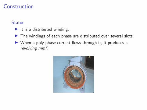
Construction
StatorI It is a distributed winding.
I The windings of each phase are distributed over several slots.
I When a poly phase current flows through it, it produces arevolving mmf.
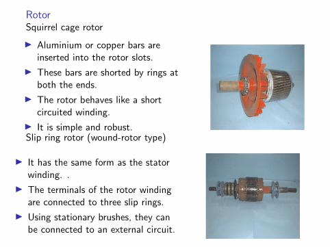
RotorSquirrel cage rotor
I Aluminium or copper bars areinserted into the rotor slots.
I These bars are shorted by rings atboth the ends.
I The rotor behaves like a shortcircuited winding.
I It is simple and robust.Slip ring rotor (wound-rotor type)
I It has the same form as the statorwinding. .
I The terminals of the rotor windingare connected to three slip rings.
I Using stationary brushes, they canbe connected to an external circuit.
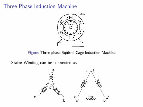
Three Phase Induction Machine
Figure: Three-phase Squirrel Cage Induction Machine
Stator Winding can be connected as
a
a′
c
c ′
b
b′
a
a′c
c ′
bb′
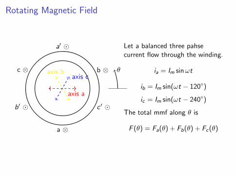
Rotating Magnetic Field
a′
a ⊗
b′
b ⊗
c ′
c ⊗
axis a
axis baxis c
θ
Let a balanced three pahsecurrent flow through the winding.
ia = Im sinωt
ib = Im sin(ωt − 120)
ic = Im sin(ωt − 240)
The total mmf along θ is
F (θ) = Fa(θ) + Fb(θ) + Fc (θ)
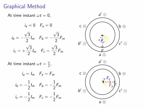
Graphical Method
At time instant ωt = 0,
ia = 0 Fa = 0
ib = −√
3
2Im Fb = −
√3
2Fm
ic = +
√3
2Im Fc =
√3
2Fm
a′
a ⊗
b′
b ⊗
c ′
c ⊗
FbFc
F
At time instant ωt = π2 ,
ia = Im Fa = Fm
ib = −1
2Im Fb = −1
2Fm
ic = −1
2Im Fc = −1
2Fm
a′
a ⊗
b′
b ⊗
c ′
c ⊗
FaFb
Fc
F
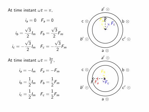
At time instant ωt = π,
ia = 0 Fa = 0
ib =
√3
2Im Fb =
√3
2Fm
ic = −√
3
2Im Fc = −
√3
2Fm
a′
a ⊗
b′
b ⊗
c ′
c ⊗ FbFc
F
At time instant ωt = 3π2 ,
ia = −Im Fa = −Fm
ib =1
2Im Fb =
1
2Fm
ic =1
2Im Fc =
1
2Fm
a′
a ⊗
b′
b ⊗
c ′
c ⊗
Fa
Fb
FcF
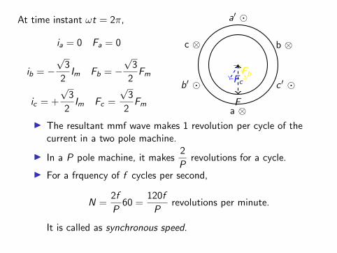
At time instant ωt = 2π,
ia = 0 Fa = 0
ib = −√
3
2Im Fb = −
√3
2Fm
ic = +
√3
2Im Fc =
√3
2Fm
a′
a ⊗
b′
b ⊗
c ′
c ⊗
FbFc
F
I The resultant mmf wave makes 1 revolution per cycle of thecurrent in a two pole machine.
I In a P pole machine, it makes2
Prevolutions for a cycle.
I For a frquency of f cycles per second,
N =2f
P60 =
120f
Prevolutions per minute.
It is called as synchronous speed.
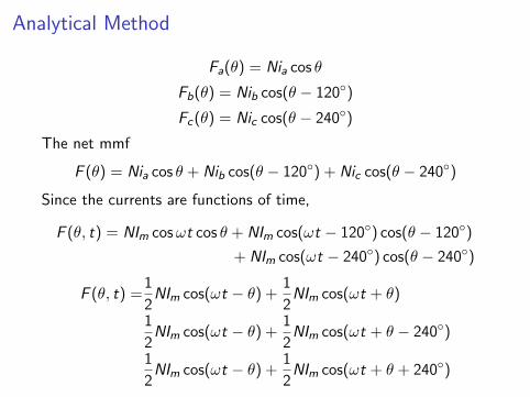
Analytical Method
Fa(θ) = Nia cos θ
Fb(θ) = Nib cos(θ − 120)
Fc (θ) = Nic cos(θ − 240)
The net mmf
F (θ) = Nia cos θ + Nib cos(θ − 120) + Nic cos(θ − 240)
Since the currents are functions of time,
F (θ, t) = NIm cosωt cos θ + NIm cos(ωt − 120) cos(θ − 120)
+ NIm cos(ωt − 240) cos(θ − 240)
F (θ, t) =1
2NIm cos(ωt − θ) +
1
2NIm cos(ωt + θ)
1
2NIm cos(ωt − θ) +
1
2NIm cos(ωt + θ − 240)
1
2NIm cos(ωt − θ) +
1
2NIm cos(ωt + θ + 240)
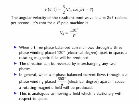
F (θ, t) =3
2NIm cos(ωt − θ)
The angular velocity of the resultant mmf wave is ω = 2πf radiansper second. It’s rpm for a P pole machine is
Ns =120f
P
I When a three phase balanced current flows through a threephase winding placed 120 (electrical degree) apart in space, arotating magnetic field will be produced.
I The direction can be reversed by interchanging any twophases.
I In general, when a n phase balanced current flows through a n
phase winding placed360
n(electrical degree) apart in space,
a rotating magnetic field will be produced.
I This is analogous to moving a field which is stationary withrespect to space.
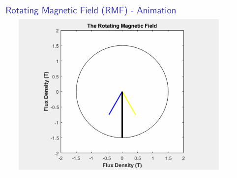
Rotating Magnetic Field (RMF) - Animation
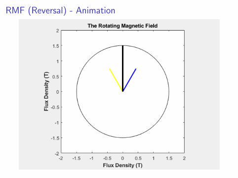
RMF (Reversal) - Animation
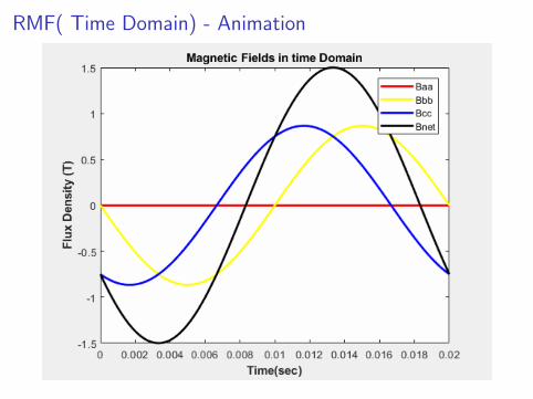
RMF( Time Domain) - Animation
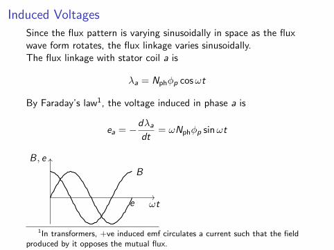
Induced Voltages
Since the flux pattern is varying sinusoidally in space as the fluxwave form rotates, the flux linkage varies sinusoidally.The flux linkage with stator coil a is
λa = Nphφp cosωt
By Faraday’s law1, the voltage induced in phase a is
ea = −dλa
dt= ωNphφp sinωt
ωt
B, e
B
e
1In transformers, +ve induced emf circulates a current such that the fieldproduced by it opposes the mutual flux.
The voltages induced in other phases are
eb = ωNphφp sin(ωt − 120)
ec = ωNphφp sin(ωt − 240)
The RMS voltage per phase is
Erms =√
2πfNphφp
Erms = 4.44fNphφp
The rotating field also induces a three phase voltage in the rotorwinding.
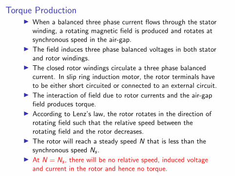
Torque ProductionI When a balanced three phase current flows through the stator
winding, a rotating magnetic field is produced and rotates atsynchronous speed in the air-gap.
I The field induces three phase balanced voltages in both statorand rotor windings.
I The closed rotor windings circulate a three phase balancedcurrent. In slip ring induction motor, the rotor terminals haveto be either short circuited or connected to an external circuit.
I The interaction of field due to rotor currents and the air-gapfield produces torque.
I According to Lenz’s law, the rotor rotates in the direction ofrotating field such that the relative speed between therotating field and the rotor decreases.
I The rotor will reach a steady speed N that is less than thesynchronous speed Ns .
I At N = Ns , there will be no relative speed, induced voltageand current in the rotor and hence no torque.
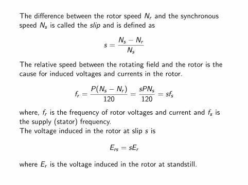
The difference between the rotor speed Nr and the synchronousspeed Ns is called the slip and is defined as
s =Ns − Nr
Ns
The relative speed between the rotating field and the rotor is thecause for induced voltages and currents in the rotor.
fr =P(Ns − Nr )
120=
sPNs
120= sfs
where, fr is the frequency of rotor voltages and current and fs isthe supply (stator) frequency.The voltage induced in the rotor at slip s is
Ers = sEr
where Er is the voltage induced in the rotor at standstill.
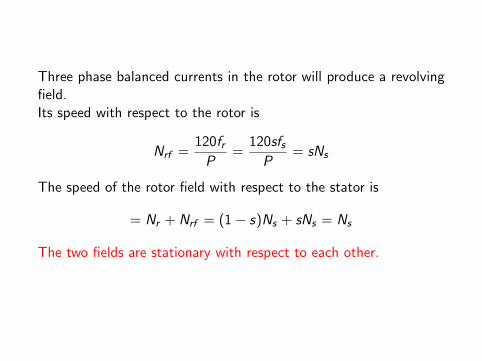
Three phase balanced currents in the rotor will produce a revolvingfield.Its speed with respect to the rotor is
Nrf =120frP
=120sfsP
= sNs
The speed of the rotor field with respect to the stator is
= Nr + Nrf = (1− s)Ns + sNs = Ns
The two fields are stationary with respect to each other.
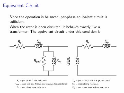
Equivalent Circuit
Since the operation is balanced, per-phase equivalent circuit issufficient.
When the rotor is open circuited, it behaves exactly like atransformer. The equivalent circuit under this condition is
Rs Xls Rr Xlr
Rcwf Xm
Rs = per phase stator resistance Xls = per phase stator leakage reactance
Rcwf = core loss plus friction and windage loss resistance Xm = magnetizing reactance
Rs = per phase rotor resistance Xls = per phase rotor leakage reactance
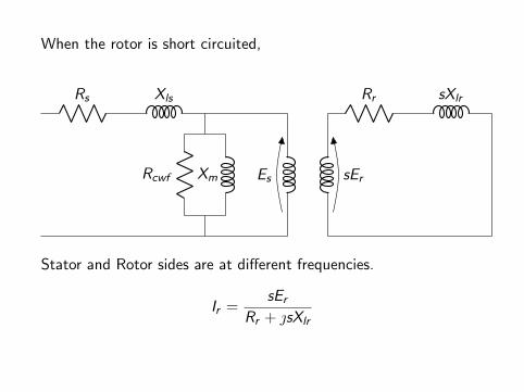
When the rotor is short circuited,
Rs Xls
Es sEr
Rr sXlr
Rcwf Xm
Stator and Rotor sides are at different frequencies.
Ir =sEr
Rr + sXlr
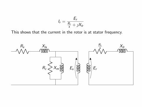
Ir =Er
Rrs + Xlr
This shows that the current in the rotor is at stator frequency.
Rs Xls
Es Er
Rrs Xlr
Rc Xm

Since the two sides are at the same frequency, the rotor sidequantities can be referrred to the stator side.
Rs XlsR′
rs X ′lr
Rcwf Xm
Rs Xls R ′r X ′lr
R′r (1−s)
sRcwf Xm
Figure: Exact Equivalent Circuit

R ′rs
= air gap power component
R ′r = rotor copper loss component
R ′r (1− s)
s= mechanical power output component
By moving the shunt path near the supply,
Rs Xls
R ′r
X ′lr
R′r (1−s)
sRcwf Xm
Figure: Approximate Equivalent Circuit
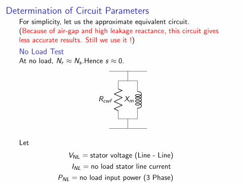
Determination of Circuit ParametersFor simplicity, let us the approximate equivalent circuit.(Because of air-gap and high leakage reactance, this circuit givesless accurate results. Still we use it !)
No Load TestAt no load, Nr ≈ Ns .Hence s ≈ 0.
Rcwf Xm
Let
VNL = stator voltage (Line - Line)
INL = no load stator line current
PNL = no load input power (3 Phase)
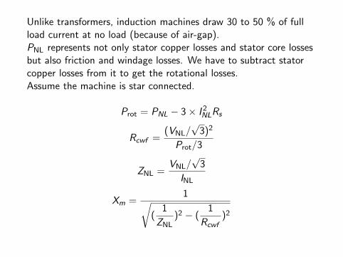
Unlike transformers, induction machines draw 30 to 50 % of fullload current at no load (because of air-gap).PNL represents not only stator copper losses and stator core lossesbut also friction and windage losses. We have to subtract statorcopper losses from it to get the rotational losses.Assume the machine is star connected.
Prot = PNL − 3× I 2NLRs
Rcwf =(VNL/
√3)2
Prot/3
ZNL =VNL/
√3
INL
Xm =1√
(1
ZNL)2 − (
1
Rcwf)2
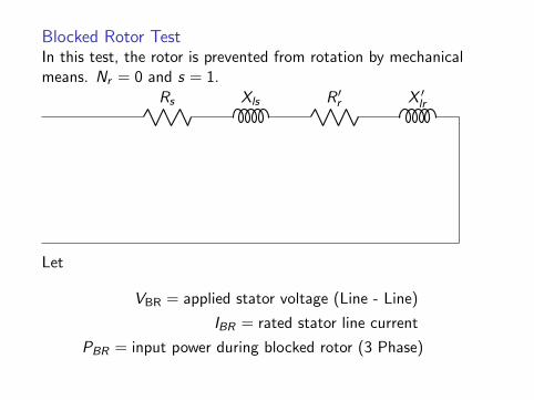
Blocked Rotor TestIn this test, the rotor is prevented from rotation by mechanicalmeans. Nr = 0 and s = 1.
Rs Xls R ′r X ′lr
Let
VBR = applied stator voltage (Line - Line)
IBR = rated stator line current
PBR = input power during blocked rotor (3 Phase)
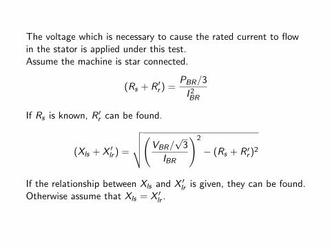
The voltage which is necessary to cause the rated current to flowin the stator is applied under this test.Assume the machine is star connected.
(Rs + R ′r ) =PBR/3
I 2BR
If Rs is known, R ′r can be found.
(Xls + X ′lr ) =
√√√√(VBR/√
3
IBR
)2
− (Rs + R ′r )2
If the relationship between Xls and X ′lr is given, they can be found.Otherwise assume that Xls = X ′lr .
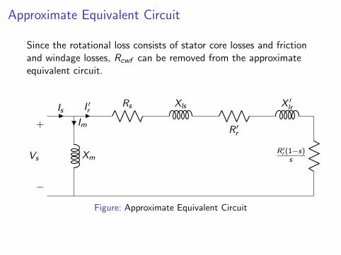
Approximate Equivalent Circuit
Since the rotational loss consists of stator core losses and frictionand windage losses, Rcwf can be removed from the approximateequivalent circuit.
Is I ′rRs Xls
R ′r
X ′lr
R′r (1−s)
s
Im
Xm
+
−
Vs
Figure: Approximate Equivalent Circuit
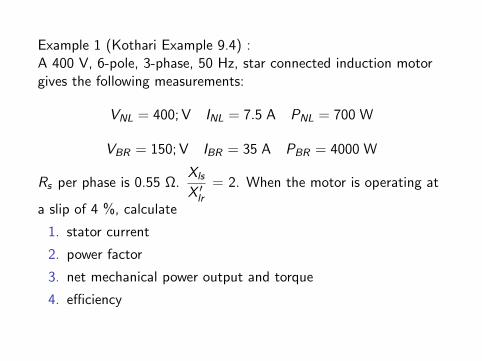
Example 1 (Kothari Example 9.4) :A 400 V, 6-pole, 3-phase, 50 Hz, star connected induction motorgives the following measurements:
VNL = 400; V INL = 7.5 A PNL = 700 W
VBR = 150; V IBR = 35 A PBR = 4000 W
Rs per phase is 0.55 Ω.Xls
X ′lr= 2. When the motor is operating at
a slip of 4 %, calculate
1. stator current
2. power factor
3. net mechanical power output and torque
4. efficiency
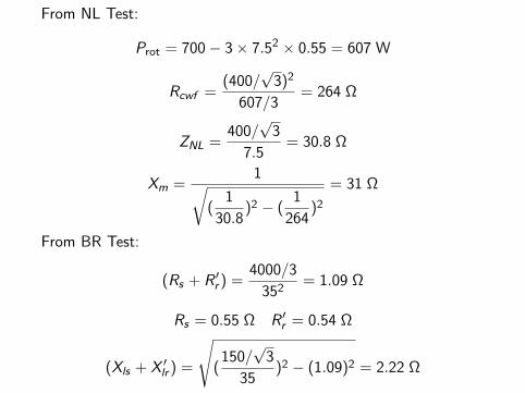
From NL Test:
Prot = 700− 3× 7.52 × 0.55 = 607 W
Rcwf =(400/
√3)2
607/3= 264 Ω
ZNL =400/√
3
7.5= 30.8 Ω
Xm =1√
(1
30.8)2 − (
1
264)2
= 31 Ω
From BR Test:
(Rs + R ′r ) =4000/3
352= 1.09 Ω
Rs = 0.55 Ω R ′r = 0.54 Ω
(Xls + X ′lr ) =
√(
150/√
3
35)2 − (1.09)2 = 2.22 Ω
Xls = 1.48 Ω X ′lr = 0.74 Ω
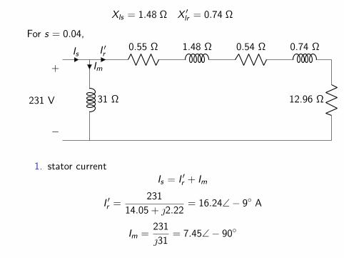
For s = 0.04,
Is I ′r0.55 Ω 1.48 Ω 0.54 Ω 0.74 Ω
12.96 Ω
Im
31 Ω
+
−
231 V
1. stator currentIs = I ′r + Im
I ′r =231
14.05 + 2.22= 16.24∠− 9 A
Im =231
31= 7.45∠− 90
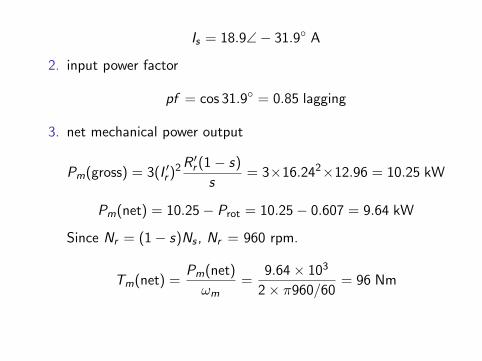
Is = 18.9∠− 31.9 A
2. input power factor
pf = cos 31.9 = 0.85 lagging
3. net mechanical power output
Pm(gross) = 3(I ′r )2R′r (1− s)
s= 3×16.242×12.96 = 10.25 kW
Pm(net) = 10.25− Prot = 10.25− 0.607 = 9.64 kW
Since Nr = (1− s)Ns , Nr = 960 rpm.
Tm(net) =Pm(net)
ωm=
9.64× 10³
2× π960/60= 96 Nm
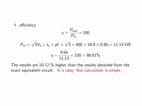
4. efficiency
η =Pout
Pin× 100
Pin =√
3Vs × Is × pf =√
3× 400× 18.9× 0.85 = 11.13 kW
η =9.64
11.13× 100 = 86.61%
The results are 10-12 % higher than the results obtained from theexact equivalent circuit. It is okay. But calculation is simple...
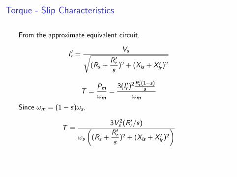
Torque - Slip Characteristics
From the approximate equivalent circuit,
I ′r =Vs√
(Rs +R ′rs
)2 + (Xls + X ′lr )2
T =Pm
ωm=
3(I ′r )2 R′r (1−s)
s
ωm
Since ωm = (1− s)ωs ,
T =3V 2
s (R ′r/s)
ωs
((Rs +
R ′rs
)2 + (Xls + X ′lr )2
)
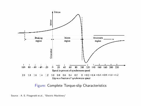
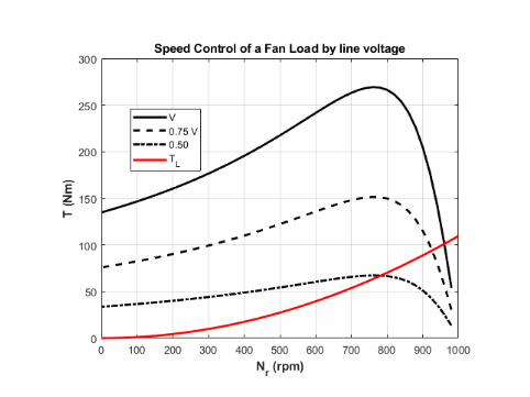
Figure: Complete Torque-slip Characteristics
Source : A. E. Fitzgerald et.al., “Electric Machinery”
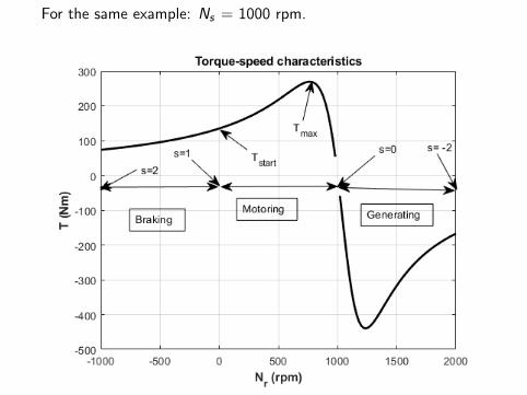
For the same example: Ns = 1000 rpm.
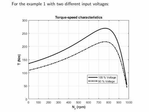
For the example 1 with two different input voltages:
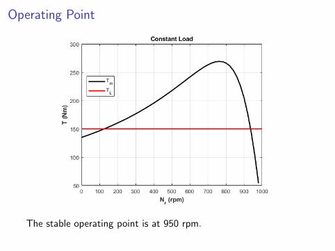
Operating Point
The stable operating point is at 950 rpm.
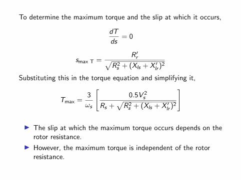
To determine the maximum torque and the slip at which it occurs,
dT
ds= 0
smax T =R ′r√
R2s + (Xls + X ′lr )2
Substituting this in the torque equation and simplifying it,
Tmax =3
ωs
[0.5V 2
s
Rs +√R2
s + (Xls + X ′lr )2
]
I The slip at which the maximum torque occurs depends on therotor resistance.
I However, the maximum torque is independent of the rotorresistance.
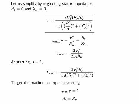
Let us simplify by neglecting stator impedance.Rs = 0 and Xls = 0.
T =3V 2
s (R ′r/s)
ωs
((R ′rs
)2 + (X ′lr )2
)
smax T =R ′rX ′lr
=Rr
Xlr
Tmax =3V 2
s
2ωsXlr
At starting, s = 1,
Tstart =3V 2
s R′r
ωs((R ′r )2 + (X ′lr )2)
To get the maximum torque at starting.
smax T = 1
Rr = Xlr
Slip Ring Induction Machine
In slip ring induction machines, by adding external resistance tothe rotor circuit
I the slip at which the maximum torque occurs can be varied.
I the starting torque can be varied.
I speed variations can be obtained.
I the starting current can also be reduced.
The maximum torque is independent of the rotor resistance
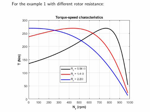
For the example 1 with different rotor resistance:
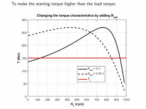
To make the starting torque higher than the load torque:
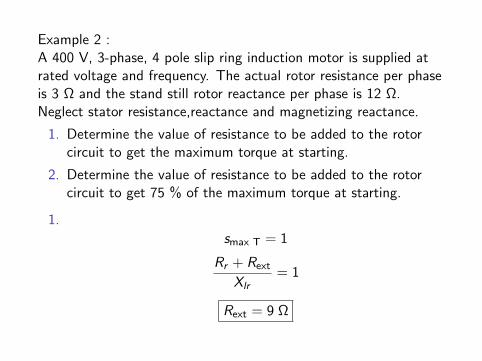
Example 2 :A 400 V, 3-phase, 4 pole slip ring induction motor is supplied atrated voltage and frequency. The actual rotor resistance per phaseis 3 Ω and the stand still rotor reactance per phase is 12 Ω.Neglect stator resistance,reactance and magnetizing reactance.
1. Determine the value of resistance to be added to the rotorcircuit to get the maximum torque at starting.
2. Determine the value of resistance to be added to the rotorcircuit to get 75 % of the maximum torque at starting.
1.
smax T = 1
Rr + Rext
Xlr= 1
Rext = 9 Ω
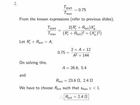
2.Tstart
Tmax= 0.75
From the known expressions (refer to previous slides),
Tstart
Tmax=
2(R ′r + Rext)X′lr
(R ′r + Rext)2 + (X ′lr )2)
Let R ′r + Rext = A,
0.75 =2× A× 12
A2 + 144
On solving this,A = 26.6, 5.4
andRext = 23.6 Ω, 2.4 Ω
We have to choose Rext such that smax T < 1.
∴ Rext = 2.4 Ω

Power Flow
Motoring Mode (0 < s < 1):
Pelectrical Pair gap Pmech (gross) Pshaft or Pout
Pstator cu loss Protor cu loss Protational loss
Pair gap = 3(I ′r )2R′r
s
Protor cu loss = sPair gap
Pmech (gross) = (1− s)Pair gap
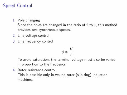
Speed Control
1. Pole changingSince the poles are changed in the ratio of 2 to 1, this methodprovides two synchronous speeds.
2. Line voltage control
3. Line frequency control
φ ∝ V
f
To avoid saturation, the terminal voltage must also be variedin proportion to the frequency.
4. Rotor resistance controlThis is possible only in wound rotor (slip ring) inductionmachines.

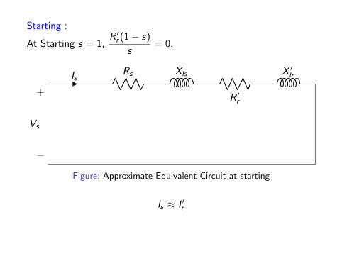
Starting :
At Starting s = 1,R ′r (1− s)
s= 0.
IsRs Xls
R ′r
X ′lr
+
−
Vs
Figure: Approximate Equivalent Circuit at starting
Is ≈ I ′r
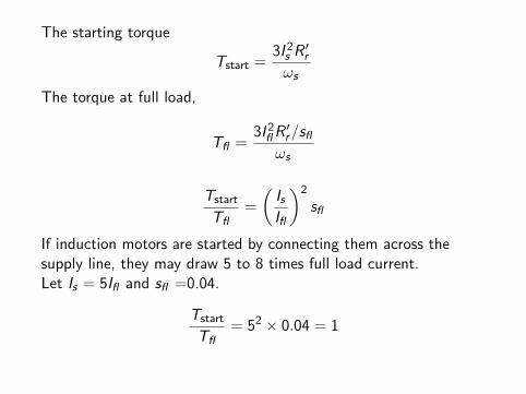
The starting torque
Tstart =3I 2
s R′r
ωs
The torque at full load,
Tfl =3I 2
flR′r/sfl
ωs
Tstart
Tfl=
(IsIfl
)2
sfl
If induction motors are started by connecting them across thesupply line, they may draw 5 to 8 times full load current.Let Is = 5Ifl and sfl =0.04.
Tstart
Tfl= 52 × 0.04 = 1
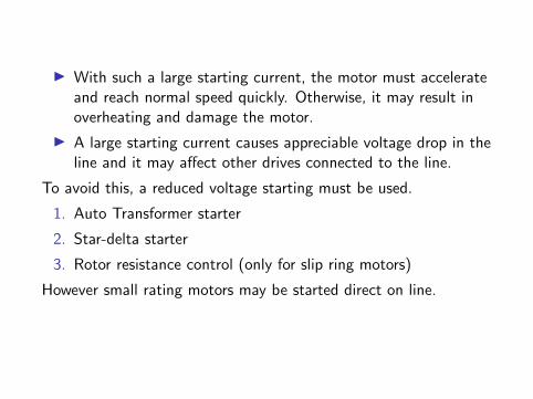
I With such a large starting current, the motor must accelerateand reach normal speed quickly. Otherwise, it may result inoverheating and damage the motor.
I A large starting current causes appreciable voltage drop in theline and it may affect other drives connected to the line.
To avoid this, a reduced voltage starting must be used.
1. Auto Transformer starter
2. Star-delta starter
3. Rotor resistance control (only for slip ring motors)
However small rating motors may be started direct on line.

Example 3 ( Kothari 9.18) : A 3-phase, wound rotor inductionmotor has a star connected rotor winding with a rotor resistance of0.12 Ω/phase. With slip-rings shorted, the motor develops a ratedtorque at a slip of 0.04 and a line current of 100 A.
1. What external resistance must be inserted in each rotor phaseto limit the starting current to 100 A?
2. What will be the per unit starting torque with the aboverotor- resistance starting?
1.
sfl = 0.04, Ifl = 100A
To have Is = Ifl , Rext is added to the rotor.

Is
R ′r
X ′lr
Rext
+
−
Vs
Figure: At starting
I 2s =
V 2s
(R ′r + Rext)2 + (X ′lr )2
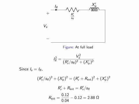
Ifl
R′r
sfl
X ′lr
+
−
Vs
Figure: At full load
I 2fl =
V 2s
(R ′r/sfl )2 + (X ′lr )2
Since Is = Ifl ,
(R ′r/sfl )2 + (X ′lr )2 = (R ′r + Rext)2 + (X ′lr )2
R ′r + Rext = R ′r/sfl
Rext =0.12
0.04− 0.12 = 2.88 Ω

2.
Tstart =3I 2
s (R ′r + Rext)
ωs
Tfl =3I 2
flR′r/sfl
ωs
Tstart
Tfl=
(R ′r + Rext)
R ′r/sfl= 1
Tstart = 1 p.u.
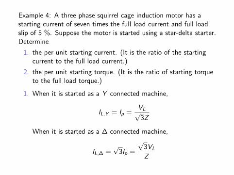
Example 4: A three phase squirrel cage induction motor has astarting current of seven times the full load current and full loadslip of 5 %. Suppose the motor is started using a star-delta starter.Determine
1. the per unit starting current. (It is the ratio of the startingcurrent to the full load current.)
2. the per unit starting torque. (It is the ratio of starting torqueto the full load torque.)
1. When it is started as a Y connected machine,
IL,Y = Ip =VL√3Z
When it is started as a ∆ connected machine,
IL,∆ =√
3Ip =
√3VL
Z
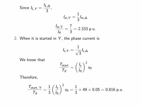
Since IL,Y =IL,∆
3,
Ist,Y =1
3Ist,∆
Ist,Y
Ifl=
7
3= 2.333 p.u.
2. When it is started in Y , the phase current is
Is,Y =1√3Is,∆
We know thatTstart
Tfl=
(IsIfl
)2
sfl
Therefore,
Tstart, Y
Tfl=
1
3
(IsIfl
)2
sfl =1
3× 49× 0.05 = 0.816 p.u.