industrial slim relay rated at 6 amps - farnell element14 · industrial slim relay rated at 6 amps...
TRANSCRIPT

Slim Relay G2RV 1
Slim Relay
G2RVIndustrial Slim Relay Rated at 6 Amps• Large plug-in terminals for reliable connection.• LED indicator, clear case, and mechanical flag allows easy
and immediate visual operation verification.• Has a maximum switching voltage of 440 VAC.• Slim outline to save space in high volume rack and PLC
applications.• Low power consumption for system energy savings.
XVDE
Model Number Structure
■ Model Number Legend
Note: LED indicator standard feature on Socket.
Ordering Information
■ List of Models
■ Relay and Socket Combinations
G2RV-SL @ @ @ - @1 2 3 4 5
1. Auxiliary Type Designation 3. Relay LEDSL: Slim relay and socket combination 0: Without LED
2. Wire Connection 4. Relay Pushbutton7: Screw terminals 0: Without pushbutton5: Push-in terminals
5. Input Voltage(Complete part numbers listed in the Relay and Socket Combinations Chart below)
Classification Enclosure rating Input voltage Type of connection
Contact formSPDT
Plug-in terminals General-purpose Unsealed AC/DC Screw terminals G2RV-SL700Push-in terminals G2RV-SL500
Input voltage Screw terminals Push-in terminals12 VDC G2RV-SL700-DC12(DC11) G2RV-SL500-DC12(DC11)24 VDC G2RV-SL700-DC24(DC21) G2RV-SL500-DC24(DC21)24 VAC/DC G2RV-SL700-AC/DC24 G2RV-SL500-AC/DC2448 VAC/DC G2RV-SL700-AC/DC48 G2RV-SL500-AC/DC48110 VAC G2RV-SL700-AC110 G2RV-SL500-AC110230 VAC G2RV-SL700-AC230 G2RV-SL500-AC230
Note: Relay and Socket Combinationsare cULus listed.
LISTED
2 Slim Relay G2RV
Specifications
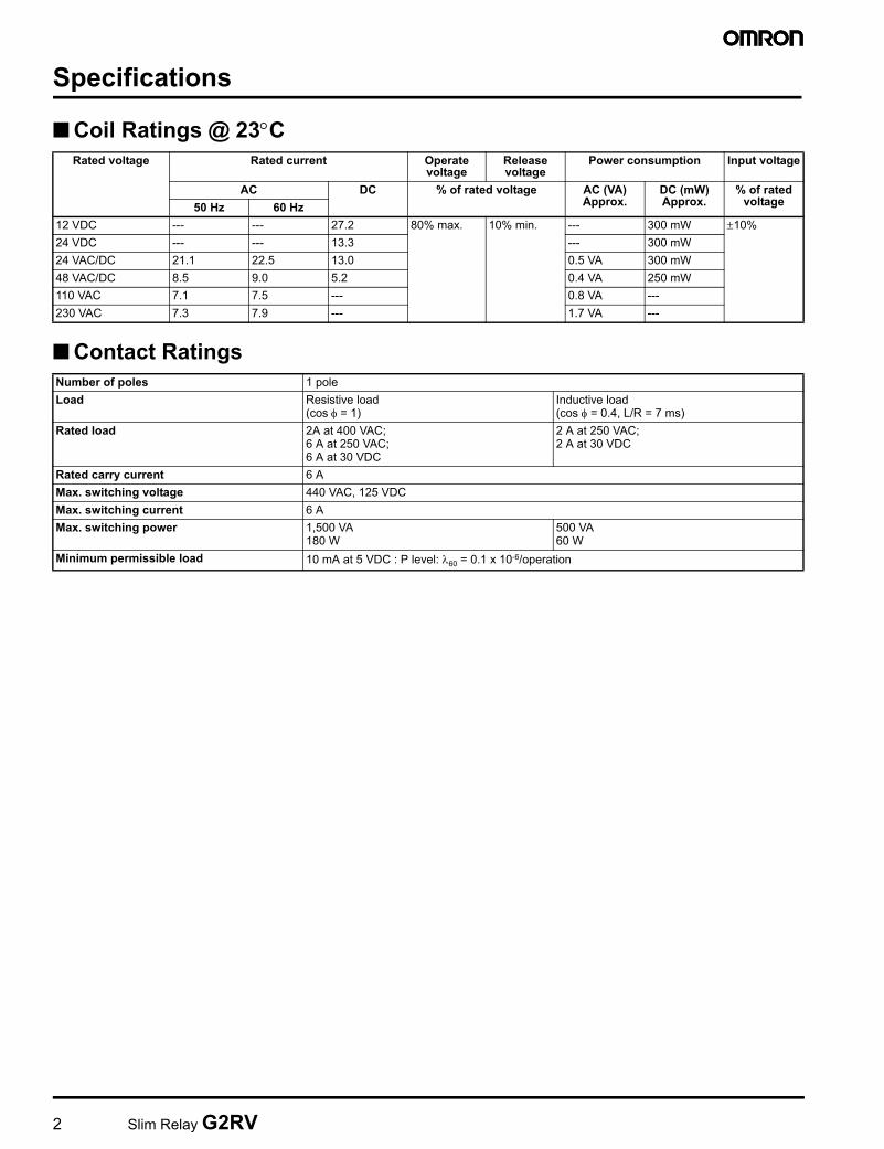
■ Coil Ratings @ 23°C
■ Contact Ratings
Rated voltage Rated current Operate voltage
Release voltage
Power consumption Input voltage
AC DC % of rated voltage AC (VA) Approx.
DC (mW) Approx.
% of rated voltage50 Hz 60 Hz
12 VDC --- --- 27.2 80% max. 10% min. --- 300 mW ±10%24 VDC --- --- 13.3 --- 300 mW24 VAC/DC 21.1 22.5 13.0 0.5 VA 300 mW48 VAC/DC 8.5 9.0 5.2 0.4 VA 250 mW110 VAC 7.1 7.5 --- 0.8 VA ---230 VAC 7.3 7.9 --- 1.7 VA ---
Number of poles 1 poleLoad Resistive load
(cos φ = 1)Inductive load (cos φ = 0.4, L/R = 7 ms)
Rated load 2A at 400 VAC;6 A at 250 VAC; 6 A at 30 VDC
2 A at 250 VAC; 2 A at 30 VDC
Rated carry current 6 AMax. switching voltage 440 VAC, 125 VDCMax. switching current 6 AMax. switching power 1,500 VA
180 W500 VA 60 W
Minimum permissible load 10 mA at 5 VDC : P level: λ60 = 0.1 x 10⁻⁶/operation
Slim Relay G2RV 3
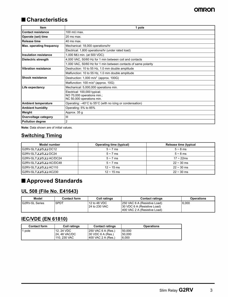
■ Characteristics
Note: Data shown are of initial values.
Switching Timing
■ Approved Standards
UL 508 (File No. E41643)
IEC/VDE (EN 61810)
Item 1 poleContact resistance 100 mΩ max.Operate (set) time 20 ms max.Release time 40 ms max.Max. operating frequency Mechanical: 18,000 operations/hr
Electrical: 1,800 operations/hr (under rated load)Insulation resistance 1,000 MΩ min. (at 500 VDC)Dielectric strength 4,000 VAC, 50/60 Hz for 1 min between coil and contacts
1,000 VAC, 50/60 Hz for 1 min between contacts of same polarityVibration resistance Destruction: 10 to 55 Hz, 1.0 mm double amplitude
Malfunction: 10 to 55 Hz, 1.0 mm double amplitudeShock resistance Destruction: 1,000 m/s2 (approx. 100G)
Malfunction: 100 m/s2 (approx. 10G)Life expectancy Mechanical: 5,000,000 operations min.
Electrical: 100,000 typical;NO 70,000 operations min.;NC 50,000 operations min.
Ambient temperature Operating: –40°C to 55°C (with no icing or condensation)Ambient humidity Operating: 5% to 85%Weight Approx. 35 gOvervoltage category IIIPollution degree 2
Model number Operating time (typical) Release time (typicalG2RV-SL7❏❏/5❏❏ DC12 5 ~ 7 ms 5 ~ 8 msG2RV-SL7❏❏/5❏❏ DC24 5 ~ 7 ms 5 ~ 8 msG2RV-SL7❏❏/5❏❏ AC/DC24 5 ~ 7 ms 17 ~ 22msG2RV-SL7❏❏/5❏❏ AC/DC48 5 ~ 7 ms 22 ~ 30 msG2RV-SL7❏❏/5❏❏ AC110 12 ~ 15 ms 22 ~ 30 msG2RV-SL7❏❏/5❏❏ AC230 12 ~ 15 ms 22 ~ 30 ms
Model Contact form Coil ratings Contact ratings OperationsG2RV-SL Series SPDT 12 to 48 VDC
24 to 230 VAC250 VAC 6 A (Resistive Load) 30 VDC 6 A (Resistive Load) 400 VAC 2 A (Resistive Load)
6,000
Contact form Coil ratings Contact ratings Operations1 pole 12, 24 VDC
24, 48 VAC/DC 110, 230 VAC
250 VAC 6 A (Res.) 30 VDC 6 A (Res.) 400 VAC 2 A (Res.)
50,000 50,0006,000
4 Slim Relay G2RV
Accessories
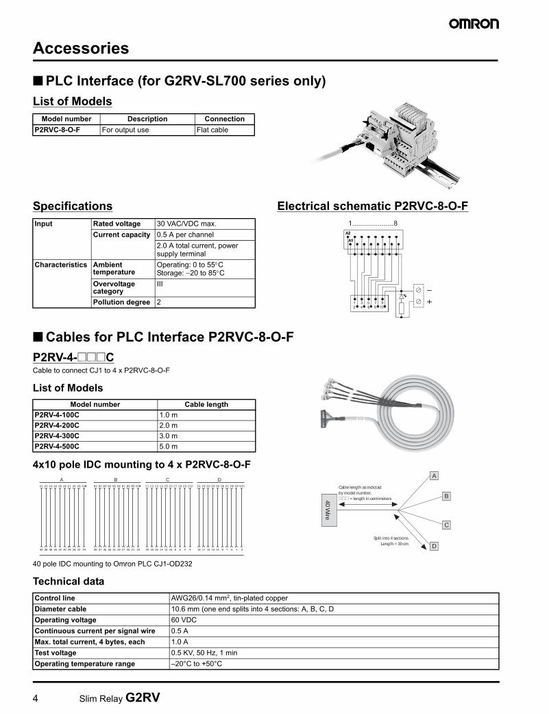
■ PLC Interface (for G2RV-SL700 series only)List of Models
Specifications Electrical schematic P2RVC-8-O-F
■ Cables for PLC Interface P2RVC-8-O-FP2RV-4-@@@CCable to connect CJ1 to 4 x P2RVC-8-O-F
List of Models
4x10 pole IDC mounting to 4 x P2RVC-8-O-F
40 pole IDC mounting to Omron PLC CJ1-OD232
Technical data
Model number Description ConnectionP2RVC-8-O-F For output use Flat cable
Input Rated voltage 30 VAC/VDC max.Current capacity 0.5 A per channel
2.0 A total current, power supply terminal
Characteristics Ambient temperature
Operating: 0 to 55°CStorage: −20 to 85°C
Overvoltage category
III
Pollution degree 2
Model number Cable lengthP2RV-4-100C 1.0 mP2RV-4-200C 2.0 mP2RV-4-300C 3.0 mP2RV-4-500C 5.0 m
AA1 A2 A3 A4 A5 A6 A7 A8 A9 A100 B1 B2 B3 B4 B5 B6 B7 B8 B9 B100 C1 C2 C3 C4 C5 C6 C7 C8 C9 C10 D1 D2 D3 D4 D5 D6 D7 D8 D9 D10
B C D
40 38 36 34 32 30 28 26 22 24 39 37 35 33 31 29 27 25 21 23 20 18 16 14 12 10 8 6 2 4 19 17 15 13 11 9 7 5 1 3
Cable length as indictadby model number.@@@ = length in centimeters
Split into 4 sectionsLength = 30 cm
40 Wire
B
A
D
C
Control line AWG26/0.14 mm2, tin-plated copperDiameter cable 10.6 mm (one end splits into 4 sections: A, B, C, DOperating voltage 60 VDCContinuous current per signal wire 0.5 AMax. total current, 4 bytes, each 1.0 ATest voltage 0.5 KV, 50 Hz, 1 minOperating temperature range –20°C to +50°C

Slim Relay G2RV 5
P2RV-A@@@CCable, single sided 10 pole IDC connector, to connect to P2RVC-8-O-F
List of Models
10 pole IDC mounting to P2RVC-8-O-F
Technical data
■ Stand-Alone Relays for MRO and Reference
Model Number Legend
List of Models
Model number Cable lengthP2RV-A100C 1.0 mP2RV-A200C 2.0 mP2RV-A300C 3.0 mP2RV-A500C 5.0 m
WHITE
GREY
PURPLE
BLUE
GREEN
YELLOW
ORANGE
RED
BROWN
BLACK
10
9
8
7
6
5
4
3
2
1
Ope
n en
d
Cable length as indictadby model number.@@@ = length in centimeters
Outer isolation removedLength = 30 cm
10 Wire
Control line AWG26/0.14 mm2, tin-plated copperDiameter cable 6.8 mmOperating voltage 60 VDCContinuous current per signal wire 0.5 AMax. total current 1.0 ATest voltage 0.5 KV, 50 Hz, 1 minOperating temperature range –20°C to +50°C
G2RV-@ - @ @ @ DC@1 2 3 4 5
1. Number of Poles 4. Contact Material1: 1 pole Blank: AgSnIn
2. Terminals 5. Rated Coil VoltageS: Plug-In 11, 21, 48
3. Relay LEDBlank: Without LED
Model number Replacement forG2RV-1-S DC11 G2RV-SL7@@/5@@ DC12(DC11)G2RV-1-S DC21 G2RV-SL7@@/5@@ DC24(DC21)
G2RV-SL7@@/5@@ AC/DC24G2RV-1-S DC48 G2RV-SL7@@/5@@ AC/DC48
G2RV-SL7@@/5@@ AC110G2RV-SL7@@/5@@ AC230
6 Slim Relay G2RV
Accessories (Order Separately)
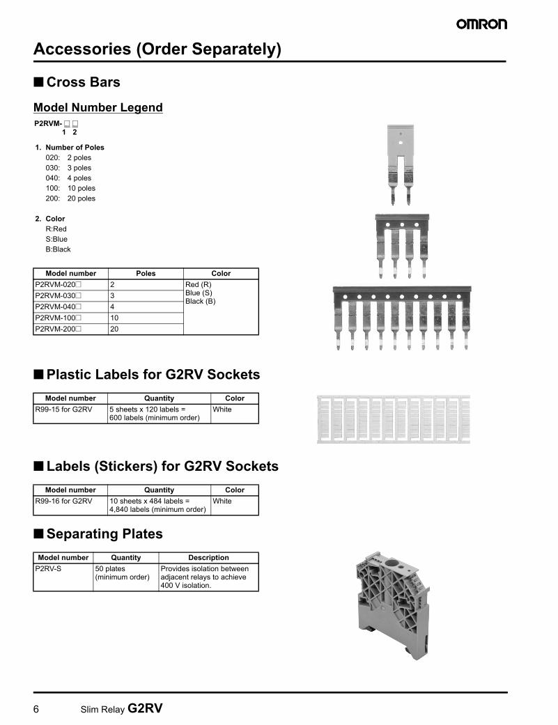
■ Cross Bars
Model Number Legend
■ Plastic Labels for G2RV Sockets
■ Labels (Stickers) for G2RV Sockets
■ Separating Plates
1. Number of Poles020: 2 poles030: 3 poles040: 4 poles100: 10 poles200: 20 poles
2. ColorR:RedS:BlueB:Black
Model number Poles ColorP2RVM-020@ 2 Red (R)
Blue (S) Black (B)
P2RVM-030@ 3P2RVM-040@ 4P2RVM-100@ 10P2RVM-200@ 20
P2RVM- @ @1 2
Model number Quantity ColorR99-15 for G2RV 5 sheets x 120 labels =
600 labels (minimum order)White
Model number Quantity ColorR99-16 for G2RV 10 sheets x 484 labels =
4,840 labels (minimum order)White
Model number Quantity DescriptionP2RV-S 50 plates
(minimum order)Provides isolation between adjacent relays to achieve 400 V isolation.

Slim Relay G2RV 7
DimensionsNote: All units are in millimeters unless otherwise indicated.
■ Complete Unit
G2RV-SL700
12
11
14
A1
A2
24 V DCTerminal Arrangement/Internal Connections(Top View)
12
11
14
A1
A2
12 V DCTerminal Arrangement/Internal Connections(Top View)
12
11
14
A1
A2
Other Coil VoltageTerminal Arrangement/Internal Connections(Top View)
Five, M2.5 x 6
6.2 max.
99.2
7.188.9
26.1
47.2
70.9
83
106.7 max.
92.7 max.35
Input circuit
8 Slim Relay G2RV
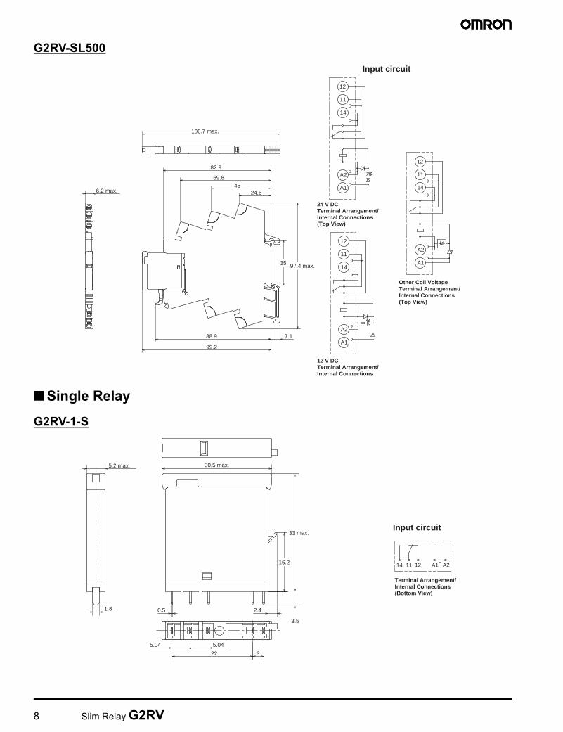
G2RV-SL500
■ Single Relay
G2RV-1-S
12
11
14
A1
A2
24 V DCTerminal Arrangement/Internal Connections(Top View)
12
11
14
A1
A2
12 V DCTerminal Arrangement/Internal Connections
12
11
14
A1
A2
Other Coil VoltageTerminal Arrangement/Internal Connections(Top View)
6.2 max.
99.2
88.9 7.1
24.646
69.8
82.9
106.7 max.
97.4 max.35
Input circuit
A2A1121114
Terminal Arrangement/Internal Connections(Bottom View)
30.5 max.
3.5
0.5 2.41.8
5.2 max.
5.04 5.04
322
33 max.
16.2
Input circuit
Slim Relay G2RV 9
Installation
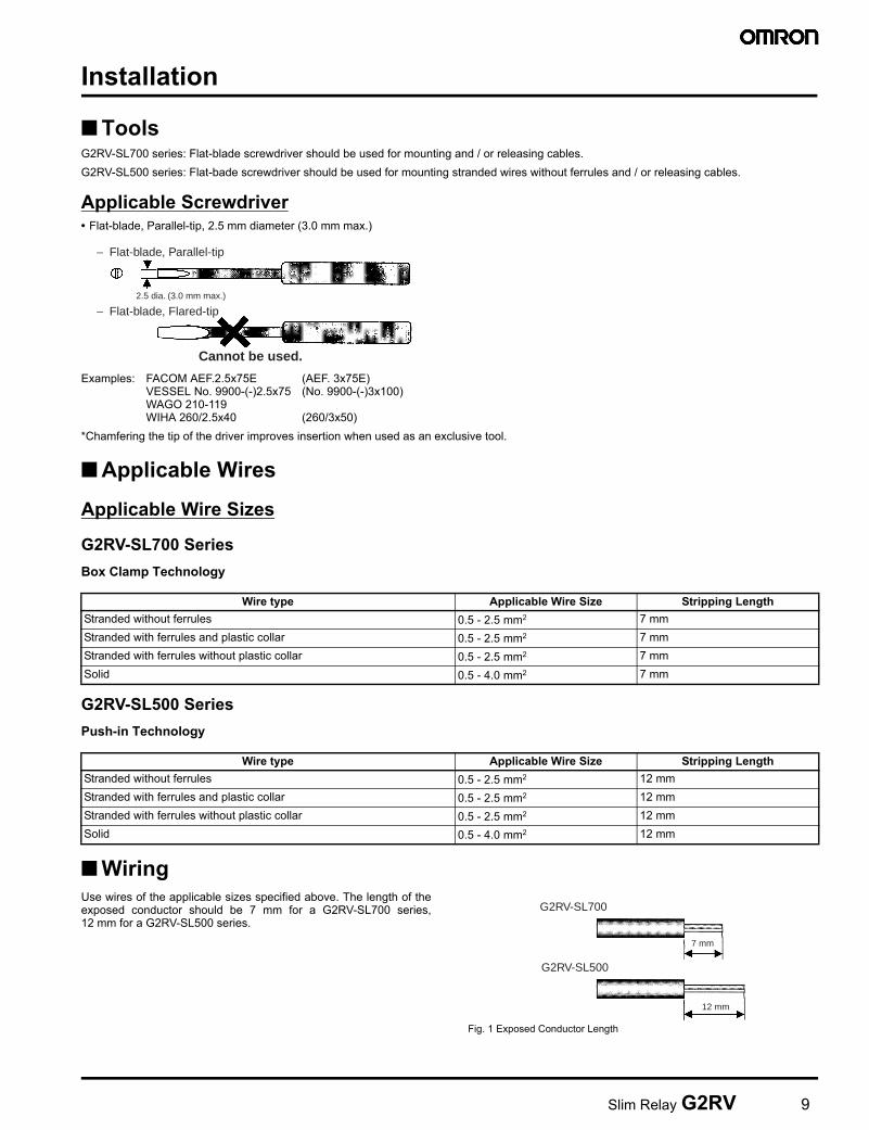
■ ToolsG2RV-SL700 series: Flat-blade screwdriver should be used for mounting and / or releasing cables.G2RV-SL500 series: Flat-bade screwdriver should be used for mounting stranded wires without ferrules and / or releasing cables.
Applicable Screwdriver• Flat-blade, Parallel-tip, 2.5 mm diameter (3.0 mm max.)
Examples: FACOM AEF.2.5x75E (AEF. 3x75E)VESSEL No. 9900-(-)2.5x75 (No. 9900-(-)3x100)WAGO 210-119WIHA 260/2.5x40 (260/3x50)
*Chamfering the tip of the driver improves insertion when used as an exclusive tool.
■ Applicable Wires
Applicable Wire Sizes
G2RV-SL700 SeriesBox Clamp Technology
G2RV-SL500 SeriesPush-in Technology
■ WiringUse wires of the applicable sizes specified above. The length of theexposed conductor should be 7 mm for a G2RV-SL700 series,12 mm for a G2RV-SL500 series.
Fig. 1 Exposed Conductor Length
− Flat-blade, Parallel-tip
− Flat-blade, Flared-tip2.5 dia. (3.0 mm max.)
Cannot be used.
Wire type Applicable Wire Size Stripping LengthStranded without ferrules 0.5 - 2.5 mm2 7 mmStranded with ferrules and plastic collar 0.5 - 2.5 mm2 7 mmStranded with ferrules without plastic collar 0.5 - 2.5 mm2 7 mmSolid 0.5 - 4.0 mm2 7 mm
Wire type Applicable Wire Size Stripping LengthStranded without ferrules 0.5 - 2.5 mm2 12 mmStranded with ferrules and plastic collar 0.5 - 2.5 mm2 12 mmStranded with ferrules without plastic collar 0.5 - 2.5 mm2 12 mmSolid 0.5 - 4.0 mm2 12 mm
7 mm
12 mm
G2RV-SL700
G2RV-SL500
10 Slim Relay G2RV
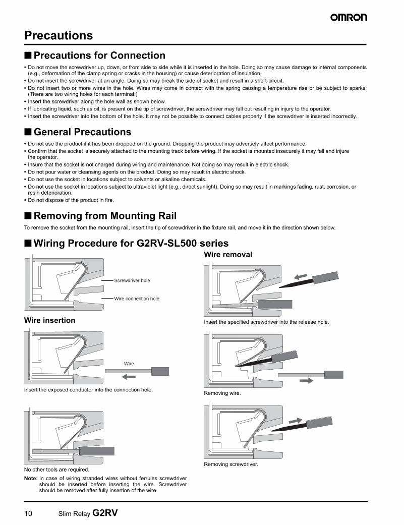
Precautions■ Precautions for Connection• Do not move the screwdriver up, down, or from side to side while it is inserted in the hole. Doing so may cause damage to internal components
(e.g., deformation of the clamp spring or cracks in the housing) or cause deterioration of insulation.• Do not insert the screwdriver at an angle. Doing so may break the side of socket and result in a short-circuit.• Do not insert two or more wires in the hole. Wires may come in contact with the spring causing a temperature rise or be subject to sparks.
(There are two wiring holes for each terminal.)• Insert the screwdriver along the hole wall as shown below.• If lubricating liquid, such as oil, is present on the tip of screwdriver, the screwdriver may fall out resulting in injury to the operator.• Insert the screwdriver into the bottom of the hole. It may not be possible to connect cables properly if the screwdriver is inserted incorrectly.
■ General Precautions• Do not use the product if it has been dropped on the ground. Dropping the product may adversely affect performance.• Confirm that the socket is securely attached to the mounting track before wiring. If the socket is mounted insecurely it may fall and injure
the operator.• Insure that the socket is not charged during wiring and maintenance. Not doing so may result in electric shock.• Do not pour water or cleansing agents on the product. Doing so may result in electric shock.• Do not use the socket in locations subject to solvents or alkaline chemicals.• Do not use the socket in locations subject to ultraviolet light (e.g., direct sunlight). Doing so may result in markings fading, rust, corrosion, or
resin deterioration.• Do not dispose of the product in fire.
■ Removing from Mounting RailTo remove the socket from the mounting rail, insert the tip of screwdriver in the fixture rail, and move it in the direction shown below.
■ Wiring Procedure for G2RV-SL500 series
Wire insertion
Insert the exposed conductor into the connection hole.
No other tools are required.Note: In case of wiring stranded wires without ferrules screwdriver
should be inserted before inserting the wire. Screwdrivershould be removed after fully insertion of the wire.
Wire removal
Insert the specified screwdriver into the release hole.
Removing wire.
Removing screwdriver.
Screwdriver hole
Wire connection hole
Wire
Terms and Conditions of Sale1. Offer; Acceptance. These terms and conditions (these "Terms") are deemed
part of all quotes, agreements, purchase orders, acknowledgments, price lists,catalogs, manuals, brochures and other documents, whether electronic or inwriting, relating to the sale of products or services (collectively, the "Products")by Omron Electronics LLC and its subsidiary companies (“Omron”). Omronobjects to any terms or conditions proposed in Buyer’s purchase order or otherdocuments which are inconsistent with, or in addition to, these Terms.
2. Prices; Payment Terms. All prices stated are current, subject to change with-out notice by Omron. Omron reserves the right to increase or decrease priceson any unshipped portions of outstanding orders. Payments for Products aredue net 30 days unless otherwise stated in the invoice.
3. Discounts. Cash discounts, if any, will apply only on the net amount of invoicessent to Buyer after deducting transportation charges, taxes and duties, and willbe allowed only if (i) the invoice is paid according to Omron’s payment termsand (ii) Buyer has no past due amounts.
4. Interest. Omron, at its option, may charge Buyer 1-1/2% interest per month orthe maximum legal rate, whichever is less, on any balance not paid within thestated terms.
5. Orders. Omron will accept no order less than $200 net billing. 6. Governmental Approvals. Buyer shall be responsible for, and shall bear all
costs involved in, obtaining any government approvals required for the impor-tation or sale of the Products.
7. Taxes. All taxes, duties and other governmental charges (other than generalreal property and income taxes), including any interest or penalties thereon,imposed directly or indirectly on Omron or required to be collected directly orindirectly by Omron for the manufacture, production, sale, delivery, importa-tion, consumption or use of the Products sold hereunder (including customsduties and sales, excise, use, turnover and license taxes) shall be charged toand remitted by Buyer to Omron.
8. Financial. If the financial position of Buyer at any time becomes unsatisfactoryto Omron, Omron reserves the right to stop shipments or require satisfactorysecurity or payment in advance. If Buyer fails to make payment or otherwisecomply with these Terms or any related agreement, Omron may (without liabil-ity and in addition to other remedies) cancel any unshipped portion of Prod-ucts sold hereunder and stop any Products in transit until Buyer pays allamounts, including amounts payable hereunder, whether or not then due,which are owing to it by Buyer. Buyer shall in any event remain liable for allunpaid accounts.
9. Cancellation; Etc. Orders are not subject to rescheduling or cancellationunless Buyer indemnifies Omron against all related costs or expenses.
10. Force Majeure. Omron shall not be liable for any delay or failure in deliveryresulting from causes beyond its control, including earthquakes, fires, floods,strikes or other labor disputes, shortage of labor or materials, accidents tomachinery, acts of sabotage, riots, delay in or lack of transportation or therequirements of any government authority.
11. Shipping; Delivery. Unless otherwise expressly agreed in writing by Omron:a. Shipments shall be by a carrier selected by Omron; Omron will not drop ship
except in “break down” situations.b. Such carrier shall act as the agent of Buyer and delivery to such carrier shall
constitute delivery to Buyer;c. All sales and shipments of Products shall be FOB shipping point (unless oth-
erwise stated in writing by Omron), at which point title and risk of loss shallpass from Omron to Buyer; provided that Omron shall retain a security inter-est in the Products until the full purchase price is paid;
d. Delivery and shipping dates are estimates only; ande. Omron will package Products as it deems proper for protection against nor-
mal handling and extra charges apply to special conditions.12. Claims. Any claim by Buyer against Omron for shortage or damage to the
Products occurring before delivery to the carrier must be presented in writingto Omron within 30 days of receipt of shipment and include the original trans-portation bill signed by the carrier noting that the carrier received the Productsfrom Omron in the condition claimed.
13. Warranties. (a) Exclusive Warranty. Omron’s exclusive warranty is that theProducts will be free from defects in materials and workmanship for a period oftwelve months from the date of sale by Omron (or such other period expressedin writing by Omron). Omron disclaims all other warranties, express or implied.(b) Limitations. OMRON MAKES NO WARRANTY OR REPRESENTATION,EXPRESS OR IMPLIED, ABOUT NON-INFRINGEMENT, MERCHANTABIL-
ITY OR FITNESS FOR A PARTICULAR PURPOSE OF THE PRODUCTS.BUYER ACKNOWLEDGES THAT IT ALONE HAS DETERMINED THAT THEPRODUCTS WILL SUITABLY MEET THE REQUIREMENTS OF THEIRINTENDED USE. Omron further disclaims all warranties and responsibility ofany type for claims or expenses based on infringement by the Products or oth-erwise of any intellectual property right. (c) Buyer Remedy. Omron’s sole obli-gation hereunder shall be, at Omron’s election, to (i) replace (in the formoriginally shipped with Buyer responsible for labor charges for removal orreplacement thereof) the non-complying Product, (ii) repair the non-complyingProduct, or (iii) repay or credit Buyer an amount equal to the purchase price ofthe non-complying Product; provided that in no event shall Omron be responsi-ble for warranty, repair, indemnity or any other claims or expenses regardingthe Products unless Omron’s analysis confirms that the Products were prop-erly handled, stored, installed and maintained and not subject to contamina-tion, abuse, misuse or inappropriate modification. Return of any Products byBuyer must be approved in writing by Omron before shipment. Omron Compa-nies shall not be liable for the suitability or unsuitability or the results from theuse of Products in combination with any electrical or electronic components,circuits, system assemblies or any other materials or substances or environ-ments. Any advice, recommendations or information given orally or in writing,are not to be construed as an amendment or addition to the above warranty.See http://www.omron247.com or contact your Omron representative for pub-lished information.
14. Limitation on Liability; Etc. OMRON COMPANIES SHALL NOT BE LIABLEFOR SPECIAL, INDIRECT, INCIDENTAL, OR CONSEQUENTIAL DAMAGES,LOSS OF PROFITS OR PRODUCTION OR COMMERCIAL LOSS IN ANYWAY CONNECTED WITH THE PRODUCTS, WHETHER SUCH CLAIM ISBASED IN CONTRACT, WARRANTY, NEGLIGENCE OR STRICT LIABILITY.Further, in no event shall liability of Omron Companies exceed the individualprice of the Product on which liability is asserted.
15. Indemnities. Buyer shall indemnify and hold harmless Omron Companies andtheir employees from and against all liabilities, losses, claims, costs andexpenses (including attorney's fees and expenses) related to any claim, inves-tigation, litigation or proceeding (whether or not Omron is a party) which arisesor is alleged to arise from Buyer's acts or omissions under these Terms or inany way with respect to the Products. Without limiting the foregoing, Buyer (atits own expense) shall indemnify and hold harmless Omron and defend or set-tle any action brought against such Companies to the extent based on a claimthat any Product made to Buyer specifications infringed intellectual propertyrights of another party.
16. Property; Confidentiality. Any intellectual property in the Products is the exclu-sive property of Omron Companies and Buyer shall not attempt to duplicate itin any way without the written permission of Omron. Notwithstanding anycharges to Buyer for engineering or tooling, all engineering and tooling shallremain the exclusive property of Omron. All information and materials suppliedby Omron to Buyer relating to the Products are confidential and proprietary,and Buyer shall limit distribution thereof to its trusted employees and strictlyprevent disclosure to any third party.
17. Export Controls. Buyer shall comply with all applicable laws, regulations andlicenses regarding (i) export of products or information; (iii) sale of products to“forbidden” or other proscribed persons; and (ii) disclosure to non-citizens ofregulated technology or information.
18. Miscellaneous. (a) Waiver. No failure or delay by Omron in exercising any rightand no course of dealing between Buyer and Omron shall operate as a waiverof rights by Omron. (b) Assignment. Buyer may not assign its rights hereunderwithout Omron's written consent. (c) Law. These Terms are governed by thelaw of the jurisdiction of the home office of the Omron company from whichBuyer is purchasing the Products (without regard to conflict of law princi-ples). (d) Amendment. These Terms constitute the entire agreement betweenBuyer and Omron relating to the Products, and no provision may be changedor waived unless in writing signed by the parties. (e) Severability. If any provi-sion hereof is rendered ineffective or invalid, such provision shall not invalidateany other provision. (f) Setoff. Buyer shall have no right to set off any amountsagainst the amount owing in respect of this invoice. (g) Definitions. As usedherein, “including” means “including without limitation”; and “Omron Compa-nies” (or similar words) mean Omron Corporation and any direct or indirectsubsidiary or affiliate thereof.
Certain Precautions on Specifications and Use1. Suitability of Use. Omron Companies shall not be responsible for conformity
with any standards, codes or regulations which apply to the combination of theProduct in the Buyer’s application or use of the Product. At Buyer’s request,Omron will provide applicable third party certification documents identifyingratings and limitations of use which apply to the Product. This information byitself is not sufficient for a complete determination of the suitability of the Prod-uct in combination with the end product, machine, system, or other applicationor use. Buyer shall be solely responsible for determining appropriateness ofthe particular Product with respect to Buyer’s application, product or system.Buyer shall take application responsibility in all cases but the following is anon-exhaustive list of applications for which particular attention must be given:(i) Outdoor use, uses involving potential chemical contamination or electricalinterference, or conditions or uses not described in this document.(ii) Use in consumer products or any use in significant quantities. (iii) Energy control systems, combustion systems, railroad systems, aviationsystems, medical equipment, amusement machines, vehicles, safety equip-ment, and installations subject to separate industry or government regulations. (iv) Systems, machines and equipment that could present a risk to life or prop-erty. Please know and observe all prohibitions of use applicable to this Prod-uct. NEVER USE THE PRODUCT FOR AN APPLICATION INVOLVING SERIOUSRISK TO LIFE OR PROPERTY OR IN LARGE QUANTITIES WITHOUTENSURING THAT THE SYSTEM AS A WHOLE HAS BEEN DESIGNED TO
ADDRESS THE RISKS, AND THAT THE OMRON’S PRODUCT IS PROP-ERLY RATED AND INSTALLED FOR THE INTENDED USE WITHIN THEOVERALL EQUIPMENT OR SYSTEM.
2. Programmable Products. Omron Companies shall not be responsible for theuser’s programming of a programmable Product, or any consequence thereof.
3. Performance Data. Data presented in Omron Company websites, catalogsand other materials is provided as a guide for the user in determining suitabil-ity and does not constitute a warranty. It may represent the result of Omron’stest conditions, and the user must correlate it to actual application require-ments. Actual performance is subject to the Omron’s Warranty and Limitationsof Liability.
4. Change in Specifications. Product specifications and accessories may bechanged at any time based on improvements and other reasons. It is our prac-tice to change part numbers when published ratings or features are changed,or when significant construction changes are made. However, some specifica-tions of the Product may be changed without any notice. When in doubt, spe-cial part numbers may be assigned to fix or establish key specifications foryour application. Please consult with your Omron’s representative at any timeto confirm actual specifications of purchased Product.
5. Errors and Omissions. Information presented by Omron Companies has beenchecked and is believed to be accurate; however, no responsibility is assumedfor clerical, typographical or proofreading errors or omissions.
Note: Specifications are subject to change. © 2008 Omron Electronics LLC Printed in U.S.A.
OMRON ELECTRONICS LLC • THE AMERICAS HEADQUARTERS
Schaumburg, IL USA • 847.843.7900 • 800.556.6766 • www.omron247.com
OMRON CANADA, INC. • HEAD OFFICEToronto, ON, Canada • 416.286.6465 • 866.986.6766 • www.omron.ca
OMRON ELETRÔNICA DO BRASIL LTDA • HEAD OFFICESão Paulo, SP, Brasil • 55.11.2101.6300 • www.omron.com.br
OMRON ELECTRONICS MEXICO SA DE CV • HEAD OFFICEApodaca, N.L. • 52.811.156.99.10 • [email protected]
OMRON ARGENTINA • SALES OFFICECono Sur • 54.11.4787.1129
OMRON CHILE • SALES OFFICESantiago 56.2206.4592
OTHER OMRON LATIN AMERICA SALES56.2206.4592
J01C-E-01a