nice · interrupt installation and contact the nice service centre for clarifications. •...
TRANSCRIPT

EN - Instructions and warnings for installation and use
IT - Istruzioni ed avvertenze per l’installazione e l’uso
FR - Instructions et avertissements pour l’installation et l’utilisation
ES - Instrucciones y advertencias para la instalación y el uso
DE - Installierungs-und Gebrauchsanleitungen und Hinweise
PL -Instrukcjeiostrzeżeniadoinstalacjiiużytkowania
NL - Aanwijzingen en aanbevelingen voor installatie en gebruik
Control unit
MC424Nice


English – 1
ENGLISH
Safety warnings• IMPORTANT! – This manual contains important instructions and warn-
ings for personal safety. Incorrect installation could cause serious physical injury. Read all parts of the manual carefully before starting work. If in doubt, interruptinstallationandcontacttheNiceServiceCentreforclarifications.
• IMPORTANT! – Important instructions: keep this manual in a safe place to enable future product maintenance and disposal procedures.
Installation warnings• Before commencing installation, check that the product is suitable for the
intended kind of use (see paragraph 2.2 “Limits of use” and chapter “Product technicalspecifications”).Ifnotsuitable,doNOTproceedwithinstallation.
• During installation, handle the product with care, avoiding the risk of crush-ing, impact, dropping or contact with any type of liquid. Never place the productnearsourcesofheatorexposetonakedflames.Thismaydamageproductcomponentsandcausemalfunctions,fireorhazardoussituations.Ifthis oc curs, suspend installation immediately and contact the Nice Service Centre.
•Nevermakemodificationstoanypartoftheproduct.Operationsotherthanasspecifiedcanonlycausemalfunctions.Themanufacturerdeclinesallliabil-ityfordamagecausedbymakeshiftmodificationstotheproduct.
•Theproductshouldnotbeusedbychildrenorpeoplewithimpairedphysical,sensorial or mental capacities or who have not received adequate training in the safe use of the product.
•Onthepowerlinetothesystem,installadevicefordisconnectionfromthepower mains with a gap between contacts that assures complete disconnec-tion in the conditions of overvoltage category III.
• Connect the control unit to an electric power line equipped with an earthing system.
•Theproduct’spackagingmaterialsmustbedisposedofinfullcompliancewith local regulations.
GENERAL SAFETY WARNINGS AND PRECAUTIONS
TheMC424controlunithasbeendesignedtocontrolWingo24Velectrome-chanical actuators, for automated swing gates or doors. IMPORTANT! – Any uses other than those specified herein or in environmental conditions other than as stated in this manual are to be considered improper and are strictly prohibited!TheMC424controlunitoperatesonthebasisofacurrentsensitivitysystemwhichcheckstheloadofthemotorsconnectedtoit.Thesystemautomaticallydetects travel stops, memorises the running time of each motor and recognises obstaclesduringnormalmovement.Thisfeaturemakesinstallationeasierasthere is no need to adjust the working times nor the leaf delay.
Thecontrolunitispre-programmedforthenormalfunctions,whilemorespe-cificfunctionscanbechosenfollowingasimpleprocedure(seechapter5).
ThecontrolunitisdesignedtobepoweredbyPS124bufferbatteriesasemer-gency power supply in the event of a mains power failure (for further information seechapter6.2).Itisalsodesignedtobeconnectedtothe“Solemyo”solarenergysystem(forfurtherinformationseechapter6.3).
PRODUCT DESCRIPTION1
In order to explain certain terms and aspects of an automatic 2-leaf swing door or gate system refer to the typical system shown in fig 1.
Key to fig. 1:1.Wingo24Velectromechanicalactuator2. Electromechanical actuator3.Lucy24flashinglight4. Key-operated selector switch5.“PHOTO”pairofphotocells6.“FOTO1”pairofphotocells7.“PHOTO2”pairofphotocells8. Control unit
In particular, please note that:
• Refer to the product instructions for the characteristics and connection of the photocells.
•Activationofthe“PHOTO”pairofphotocellshavenoeffectonthegatedur-ing opening, while they reverse movement during closing.
INSTALLATION2
Summary GENERAL SAFETY WARNINGS AND PRECAUTIONS . . . . . . . . . . 1
1 – PRODUCT DESCRIPTION . . . . . . . . . . . . . . . . . . . . . . . . . . . . . . . . . 1
2 – INSTALLATION . . . . . . . . . . . . . . . . . . . . . . . . . . . . . . . . . . . . . . . . . . 1
2.1 - PRELIMINARY CHECKS FOR INSTALLATION . . . . . . . . . . . . 2
2.2 - PRODUCT APPLICATION LIMITS . . . . . . . . . . . . . . . . . . . . . . 2
2.3 - INSTALLATION . . . . . . . . . . . . . . . . . . . . . . . . . . . . . . . . . . . . . 2
2.4 - ELECTRICAL CONNECTIONS . . . . . . . . . . . . . . . . . . . . . . . . . 2 2.4.1 - Notes on connections . . . . . . . . . . . . . . . . . . . . . . . . . . 3 2.4.2 - Type of ALT input . . . . . . . . . . . . . . . . . . . . . . . . . . . . . 3 2.4.3 - Examples of photocell connections: with the “Everything in stand by” function active and the Phototest function disabled . . . . . . . . . . . . . . . . . . . . . 3 2.4.4 - Examples of photocell connections: with the Phototest function active and the “Everything in stand by” function disabled . . . . . . . . . . . . . . . . . . . . . . . . . . . . . . 3
2.5 - INITIAL START-UP AND ELECTRICAL CONNECTIONS . . . . 3
2.6 - AUTOMATIC LIMIT SWITCH SEARCH . . . . . . . . . . . . . . . . . . 3
3 – TESTING AND COMMISSIONING . . . . . . . . . . . . . . . . . . . . . . . . . . . 4
3.1 - TESTING . . . . . . . . . . . . . . . . . . . . . . . . . . . . . . . . . . . . . . . . . . 4
3.2 - COMMISSIONING . . . . . . . . . . . . . . . . . . . . . . . . . . . . . . . . . . . 4
4 – DIAGNOSTICS . . . . . . . . . . . . . . . . . . . . . . . . . . . . . . . . . . . . . . . . . . 4
5 – PROGRAMMING . . . . . . . . . . . . . . . . . . . . . . . . . . . . . . . . . . . . . . . . 4
5.1 - PRESET FUNCTIONS . . . . . . . . . . . . . . . . . . . . . . . . . . . . . . . . 4
5.2 - PROGRAMMABLE FUNCTIONS . . . . . . . . . . . . . . . . . . . . . . . 4 5.2.1 - Direct programming . . . . . . . . . . . . . . . . . . . . . . . . . . . 4 5.2.2 - First level programming: first part . . . . . . . . . . . . . . . . 4 5.2.3 - First level programming: second part . . . . . . . . . . . . . 5 5.2.4 - Second level functions . . . . . . . . . . . . . . . . . . . . . . . . . 5
5.3 - PROGRAMMING MODES . . . . . . . . . . . . . . . . . . . . . . . . . . . . . 5 5.3.1 - First level programming: functions . . . . . . . . . . . . . . . 6 5.3.2 - Second level programming: parameters . . . . . . . . . . . 6 5.3.3 - Deletion of memory . . . . . . . . . . . . . . . . . . . . . . . . . . . . 7 5.3.4 - Example of first level programming . . . . . . . . . . . . . . 7 5.3.5 - Example of second level programming . . . . . . . . . . . . 7 5.3.6 - Programming diagrame . . . . . . . . . . . . . . . . . . . . . . . . 8
6 – FURTHER DETAILS: accessories . . . . . . . . . . . . . . . . . . . . . . . . . . . 9
6.1 - CONNECTING A RADIO RECEIVER . . . . . . . . . . . . . . . . . . . . 9
6.2 - CONNECTING MODEL PS124 BUFFER BATTERY . . . . . . . . 9
6.3 - CONNECTING THE SOLEMYO SYSTEM . . . . . . . . . . . . . . . . 9
7 – TROUBLESHOOTING (troubleshooting guide) . . . . . . . . . . . . . . . . 9
8 – PRODUCT MAINTENANCE . . . . . . . . . . . . . . . . . . . . . . . . . . . . . . . . 9
DISPOSAL OF THE PRODUCT . . . . . . . . . . . . . . . . . . . . . . . . . . . . . 9
TECHNICAL CHARACTERISTICS OF THE PRODUCT . . . . . . . . . 10
EC DECLARATION OF CONFORMITY . . . . . . . . . . . . . . . . . . . . . . 10
RADIO RECEIVER: SMXI - SMXIS . . . . . . . . . . . . . . . . . . . . . . . . . 11
1 - PRODUCT DESCRIPTION . . . . . . . . . . . . . . . . . . . . . . . . . . . . . 11 2 - AERIAL INSTALLATION . . . . . . . . . . . . . . . . . . . . . . . . . . . . . . . 11 3 - MEMORISING A REMOTE CONTROL . . . . . . . . . . . . . . . . . . . 11 4 - DELETING ALL TRANSMITTERS . . . . . . . . . . . . . . . . . . . . . . . 12
TECHNICAL CHARACTERISTICS OF THE PRODUCT . . . . . . . . . 12
IMAGES . . . . . . . . . . . . . . . . . . . . . . . . . . . . . . . . . . . . . . . . . . . . . I-V
Original instructions
EN

2 – English
•Activationofthe“PHOTO1”pairofphotocellsstopsboththeopeningandclosing manoeuvres.
•Activationofthe“PHOTO2”pairofphotocells(connectedtothesuitablypro-grammedAUXinput)hasnoeffectduringclosingwhiletheyinvertmovementduring opening.
Tocheckthepartsofthecontrolunitseefig.2.
Key to fig. 2:A. 24VpowersupplyconnectorB. M1motorconnectorC. PS124bufferbatteryconnector/Solemyosolarenergysupply system(forfurtherdetailsseechapter6.3)D. 500mAFtypeservicesfuseE. SelectorswitchfordelayingtheopeningofmotorM1orM2F. M2 motor terminalG. Flashing light output terminalH. Gate open indicator or electric lock output terminalI. 24VdcterminalsforservicesandphototestL. Input terminalsL1…L5. Input and programming LEDsM. TerminalforradioaerialN. “SM” radio receiver connectorO. Programming/diagnosticsconnectorP1, P2, P3. Programming buttons and LEDs
2.1 - Preliminary checks for installationBefore proceeding with installation, check the condition of the product compo-nents, suitability of the selected model and conditions of the intended installa-tion environment:• Ensure that all conditions of use remain within the limits of product application andwithinthe“Producttechnicalspecifications”.• Ensure that the selected installation environment is compatible with the over-all dimensions of the product (fig. 3).• Ensure that the selected surfaces for product installation are solid and guar-anteeastablefixture.•Makesurethatthefixingzoneisnotsubjecttoflooding.Ifnecessary,mountthe product raised from the ground.• Ensure that the space around the product enables easy and safe completion of manual manoeuvres.• Make sure that the automation is provided with mechanical stops on both closing and opening.
2.2 - Product application limitsTheproductmaybeusedexclusivelywithWG4024,WG5024,XME2024,TN2020,TN2020L,TOO3024,TOO4524 gearmotors.
2.3 - InstallationToinstallthecontrolunit,proceedasshowninfig. 4. Also observe the follow-
ing warnings:•ThecontrolunitissuppliedinanenclosurethatifcorrectlyinstalledassuresanIP54protectionrating.Thecontrolunitisthereforesuitableforinstallationoutdoors.•Fixthecontrolunittoaflat,vertical,non-removablesurfacethatisadequatelyprotected from potential impacts. Important!–Thebottomofthecontrolunitmustbeatleast40cmfromtheground.• Insert the dedicated cable clamps or pipe glands into the lower part of the enclosure (fig. 4).Important! – If the cable protection tubes end in a pit, it is likely that condensation will form inside the control unit, which will damage the electronic board. In this case, protect the control unit adequately so as to pre-vent the formation of condensation.•Thecableclampscanbeinsertedonthelongsideoftheenclosureonlyifthecontrol unit is installed in a protected indoor environment.Toinstalltheotherdevicespresent intheautomation,refertotherelevantinstruction manuals.
2.4 - Electrical connections
IMPORTANT!– All electrical connections must be made with the unit disconnected from the mains power supply and with the buffer battery disconnected, if present in the automation.– Connections must be made exclusively by qualified personnel.– Make sure that all the electric cables used are of a suitable type.
01. Loosen the screws of the cover.02. Prepare the electrical cable routing holes.03. Connect the cables as shown in the wiring diagram in fig. 5.Toconnect
the electric power cable, see fig. 6. Note – To facilitate cable connections, the terminals can be removed from their seats .
• WiththeexceptionofthephotocellinputswhenthePHOTOTESTfunctionisactivated,iftheinputsoftheNC(NormallyClosed)contactsarenotinusetheyshouldbejumpedwiththe“COMMON”terminal.Refertoparagraph2.4.3 for further information.
• If there is more than one NC contact on the same input, they must be con-nected in SERIES.
• IftheinputsoftheNO(NormallyOpen)contactsarenotusedtheyshouldbeleft free.
• IfthereismorethanoneNOcontactonthesameinput,theymustbecon-nected in PARALLEL.
• Thecontactsmustbeelectromechanicalandpotential-free.Stageconnec-tions,suchasthosedefinedas“PNP”,“NPN”,“OpenCollector”,etc.arenotallowed.
• If the leafs overlap, use jumper E (Fig. 6)toselectwhichmotorstartsupfirstduring opening.
Key to figs. 2 - 5a - 5b - 5c: Terminals Function Description Type of cableL - N - Power supply line Mains power supply 3x1,5mm2
1÷3 Motor1 M1motorconnection 3x1,5mm2
1÷3 Motor 2 M2motorconnection(Note1) 3x1,5mm2
4÷5 Flashing light Connectionofflashinglight24V max25W 2x1mm2
6÷7 Open Gate indicator /Elect.Lock
ConnectionforOpenGateIndicator24V max5WorElectriclock12V max 25VA(“Seechapter5-Programing”)
SCA:2x0,5mm2 Electriclock:2x1mm2
8 Common24V (with Everythinginstandby/phototest)
PowerSupply+24V forTXphotocellswithphototest(max.100mA);“COM-MON”forallinputs,safety,with“Everythinginstandby”functionactivated(Note2)
1x0,5mm2
9 0V Powersupply0V for services 1x0,5mm2
10 24V Powerinputforservices,without“Everythinginstandby”(24V max200mA) 1x0,5mm2
11 Common24V Commonforallinputs(+24V )without“Everythinginstandby” 1x0,5mm2
12 STOP InputwithSTOPfunction(emergency,safetyshutdown)(Note3) 1x0,5mm2
13 PHOTO NCInputforsafetydevices(photocells,sensitiveedges) 1x0,5mm2
14 PHOTO1 NCInputforsafetydevices(photocells,sensitiveedges) 1x0,5mm2
15 STEPBYSTEP Inputforcyclicalfunctioning(OPEN-STOP-CLOSE-STOP) 1x0,5mm2
16 AUX Auxiliaryinput(Note4) 1x0,5mm2
17÷18 Aerial Connection for the radio receiver aerial screenedcabletypeRG58
Note 1 – This is not used for single leaf gates (the control unit automatically recognises if only one motor has been installed) .Note 2 – The “Everything in stand by” function serves to reduce consumptions . For further details on the electrical connections refer to paragraph 2 .4 .1 ““Every-thing in stand by/Phototest connection” and for programming refer to chapter 5 .2 .3 “Everything in stand by/Phototest function” .Note 3 – The STOP input can be used for “NC” or constant resistance 8.2 kΩ contacts (please refer to the “Programming” chapter)Note 4 – The AUX factory auxiliary input is programmed with the “Partial open type 1” function but can be programmed with any of the following functions:
Function Input type DescriptionPARTIALOPENTYPE1 NO Fully opens the upper leafPARTIALOPENTYPE2 NO OpensthetwoleafhalfwayOPEN NO Onlycarriesouttheopeningmanoeuvre
EN

2.5 - Initial start-up and electrical connectionsIMPORTANT! – Connections must be made exclusively by qualified per-sonnel.
Afterpoweringupthecontrolunit,checkthatalltheLEDsflashrapidlyforafewseconds, then perform the following checks:1.Checkthatthereisavoltageofapproximately30Vdconterminals9-10.If
not, unplug the unit immediately and carefully check the connections and input voltage.
2.Afterinitiallyflashingrapidly,theP1LEDwillindicatethecontrolunitiswork-ingcorrectlybyflashingregularlyat1secondintervals.Whenthereisavari-ationintheinputs,the“P1”ledwillrapidlyflashtwicetoshowthattheinputhas been recognised.
3. If the connections are correct, the LED for the “NC”-type inputs will be on, whilethoseforthe“NO”typeinputsmustbeoff.Seefig. A and Table 2.
TABLE 2INPUT INPUT TYPE STATUS LEDSTOP STOPNC L1On CONSTANTRESISTANCE L1On STOP8.2KΩPHOTO NC L2OnFOTO1 NC L3OnSTEP-BY-STEP NO L4OffAUX OPENPARTIALLYtype1-NO L5Off OPENPARTIALLYtype2-NO L5Off OPENONLY-NO L5Off CLOSEONLY-NO L5Off FOTO2-NC L5On
4. Check that the relative LEDs switch on and off when the devices connected to the inputs are operated.
5. Check that by pressing P2 both motors perform a short opening manoeuvre, andthemotoroftheupperleafstartsfirst.Blockthemanoeuvrebypress-ing P2 again. If the motors do not start up for opening, invert the polarities ofthemotorcables.If,however,thefirstonetomoveisnottheupperleaf,operate jumper E (fig. 2).
2.6 - Automatic search system for the limit switchesOnthesuccessfulcompletionofthevariouscontrols,starttheautomaticsearchsystemphaseforthelimitswitches.ThisworkisnecessaryastheMC424con-trol unit must “measure” how long the opening and closing manoeuvres take Thisprocedureiscompletelyautomaticanddetectsthemechanicalopeningand closing stops by measuring the load on the motors.
Warning! – If this procedure has already been carried out, in order to reactivate it, the user must first delete the memory (see the “Memory de letion” chapter). In order to check whether the memory contains any li mit switch parameters, turn the power supply to the control unit on and then off again . If all the LEDs flash rapidly for approximately 6 sec-onds, the me mory is empty. If, however, they only flash for 3 seconds, the memory already contains some limit switch parameters.
Before starting limit switch searching, make sure that all the safety devices areenabled(STOP,PHOTOandPHOTO1).Theprocedurewillbeimmediatelyinterrupted if a safety device triggers or a command arrives. The leafs MUST be positioned at approximately mid-travel.
Procedure – Press the P2 button (fig. 2) to start begin searching which includes:- Bothmotorsopenbriefly.- Motor closes the lower leaf until it reaches the mechanical closing stop.- Theupperleafmotorclosesuntilitreachesthemechanicalclosingstop.- Themotoroftheupperleafbeginstoopen.- After the programmed delay, opening of the lower leaf begins. If the delay isinsufficient,blockthesearchbypressingP1(fig. 2),thenmodifythetime(seechapter5).
- Thecontrolunitmeasuresthemovementrequiredforthemotorstoreachtheopening mechanical stops.
- Completeclosingmanoeuvre.Themotorscanstartatdifferenttimes,theaimis to prevent the leafs from shearing by maintaining a suitable delay.
English – 3
2.4.1 - Notes about connectionsMost connections are extremely simple and many of them are direct connec-tionstoasingleuserpointorcontact.Thefollowingfiguresshowexamplesofhow to connect external devices:
• Everything in stand by / Phototest connectionThe“Everythinginstandby”functionisactiveasstandard.Itisexcludedauto-matically only when the Phototest function is activated. Note - The “Everything in stand by” and Phototest functions are alternatives as one excludes the other .The“Everythinginstandby”functionallowsconsumptionstobereduced.Three
types of connections can be obtained:- with “Everything in stand by” active (energy saving);seeelectricaldiagramin
fig. 5a-standardconnection:without“Everythinginstandby”andwithout“Phototest”;
see electrical diagram in fig. 5b-without“Everythinginstandby”andwith“Phototest”;seeelectricaldiagramin
fig. 5cWhenthe“Everythinginstandby”functionisactive,1minuteaftertheendofa manoeuvre the control unit goes into “Everything in stand by”, turning off the InputsandOutputstoreduceconsumptions.Thestatusisindicatedbythe“OK”LEDwhichbeginstoflashmoreslowly.WARNING – If the control unit is powered fromaphotovoltaicpanel(“Solemyo”system)orabufferbattery,the“Everythinginstand by” function must be activated as shown in the electrical diagram in fig. 5a.Whenthe“Everythinginstandby”functionisnotrequired,the“Phototest”func-tionmaybeactivated.Thisverifiesatthebeginningofamanoeuvrethattheconnectedphotocellsoperatecorrectly.Tousethisfunction,firstconnectthephotocells appropriately (see electrical diagram in fig. 5c)andthenactivatethefunction. Note – When the phototest is activated, the inputs subjected to the test procedure are PHOTO, PHOTO1 and PHOTO2 . If one of these inputs is not used it must be connected to terminal no . 8 .
• Key switch connectionExample 1 (fig. 7a): HowtoconnecttheswitchinordertoperformtheSTEP-BY-STEPandSTOPfunctionsExample 2 (fig.7b): HowtoconnecttheswitchinordertoperformtheSTEP-BY-STEPandoneoftheauxiliaryinputfunctions(PARTIALOPENING,OPENONLY,CLOSEONLY…)Note – For electrical connections with the “Everything in stand by” function active, see “Everything in stand by/Phototest function” in this paragraph 2 .4 .1 .
• Connection for Gate Open Indicator / Electric lock (fig. 8) If the gate open indicator has been programmed, the output can be used as an opengateindicatorlight.Thelight,flashesslowlyduringopeningandquicklyduringclosing;Ifitisonbutdoesnotflash,thisindicatesthatthegateisopen.If the light is off, the gate is closed. Se the output has been programmed as an electric lock, it is activated for 3 seconds each time opening begins.
2.4.2 - STOP type inputTheMC424controlunitcanbeprogrammedfortwotypesofSTOPinput:
- NC type STOP for connecting up to NC type contacts.- Constant resistance STOP. It enables the user to connect up to the con-trolunitofdeviceswith8.2kΩconstantresistance(e.g.sensitiveedges).Theinputmeasuresthevalueoftheresistanceanddisablesthemanoeuvrewhen the resistance is outside the nominal value. Devices with normally open “NO”ornormallyclosed“NC”contacts,ormultipledevices,evenofdifferenttypes,canbeconnectedtotheconstantresistanceSTOPinput,providedthatappropriateadjustmentsaremade;seeTable1.
WARNING! – If the constant resistance STOP input is used to connect devices with safety functions, only the devices with 8.2 KΩ constant will resistance output guarantee the fail-safe category 3.
Notes to Table 1:Note 1 – Any number of NO devices can be connected to each other in paral-lel, with an 8.2 KΩ termination resistance (fig. 9a) . For electrical connections with the “Everything in stand by” function active, see “Everything in stand by/Phototest function” in this paragraph 2 .4 .1 .Note 2 – The NO and NC combination can be obtained by placing the two con-tacts in parallel, and placing an 8.2 KΩ resistance in series with the NC contact. It is, therefore, possible to combine 3 devices: NO, NC and 8.2 KΩ (fig. 9b) .Note 3 – Any number of NC devices can be connected in series to each other and to an 8.2 KΩ resistance (fig. 9c) .Note 4 – Only one device with an 8.2 KΩ constant resistance output can be connected; multiple devices must be connected “in cascade” with a single 8 .2 KΩ termination resistance (fig. 9d) .
A
1stdevicetype:
NO NC 8,2 KΩ
In parallel (note 1) (note 2) Inparallel
NC (note 2) Inseries(note 3) Inseries
8,2 KΩ In parallel In series (note 4)
TABLE 1
seco
nd d
evic
e ty
pe:
CLOSE NO OnlycarriesouttheclosingmanoeuvrePHOTO2 NC PHOTO2functionDISABLED — No function
EN

4 – English
- End of the procedure with memorisation of all measurements.All these phases must take place one after the other without any interference from the operator. If the procedure does not continue correctly, it must be interruptedwiththeP1button.Repeattheprocedure,modifyingsomeparam-eters if necessary, for example the current sensitivity cut-in thresholds (see chapter5).
Thesearethemostimportantphasesofautomationset-upforensuringmaxi-mumsystemsafety.Thetestcanalsobeperformedasaperiodiccheckofautomationdevices.Testingandcommissioningoftheautomationmustbeperformedbyskilledandqualifiedpersonnel,whoareresponsibleforthetestsrequired to verify the solutions adopted according to the risks present, and for ensuring observance of all legal provisions, standards and regulations, and in particularallrequirementsofthestandardEN12445,whichestablishesthetestmethods for checking automations for doors and gates.Theadditionaloroptionaldevicesmustundergoaspecifictestforfunctional-ity and correct interaction with MC424. Refer to the instruction manuals of the individual devices.
3.1 - TestingThetestingsequencereferstothecontrolunitprogrammedwiththepresetfunctions.Seeparagraph5.1:•MakesurethattheactivationoftheSTEP-BY-STEPinputgeneratesthefol-lowingsequenceofmovements:“Open,Stop,Close,Stop”.
•MakesurethattheactivationoftheAUXinput(Type1partialopeningfunc-tion)managesthe“Open,Stop,Close,Stop”sequenceofthemotoroftheupper leaf only, while the motor of the lower leaf remains in the closed posi-tion.
• Perform an opening manoeuvre and check that:
- thegatecontinuestheopeningmanoeuvrewhenPHOTOisengaged
- theopeningmanoeuvrestopswhenPHOTO1isengagedandonlycontinueswhenPHOTO1isdisengaged
- ThemanoeuvrestopswhenPHOTO2(ifinstalled)isengagedandtheclosingmanoeuvre starts
• Make sure that the motor switches off when the door reaches the mechanical stop.
• Perform an opening manoeuvre and check that:
- ThemanoeuvrestopswhenPHOTOisengagedandtheopeningmanoeuvrestarts
- ThemanoeuvrestopswhenPHOTO1isengagedandtheopeningmanoeu-vrestartsagainwhenPHOTO1isdisengaged
- thegatecontinuestheclosingmanoeuvrewhenPHOTO2isengaged
•CheckthatthestoppingdevicesconnectedtotheSTOPinputimmediatelystop all movement.
• Check that the level of the obstacle detection system is suitable for the appli-cation:
- During both the opening and the closing manoeuvres, prevent the leaf from moving by placing an obstacle and check that the manoeuvre inverts before exceeding the force set down by law
•Otherchecksmayberequireddependingonwhichdevicesareconnectedtothe inputs.
Warning – If an obstacle is detected as moving in the same direction for 2 consecutive manoeuvres in the same direction, the control unit par-tially inverts both motors for just 1 second . At the following command, the leafs begin the opening manoeuvre and the first current sensitiv-ity cut-in for each motor is considered as a mechanical stop during the opening cycle. The same happens when the mains power supply is switched on: the first command is always an opening manoeuvre and the first obstacle is always considered as a mechanical stop during the opening cycle.
3.2 - CommissioningCommissioning can only be performed after positive results of all test phases.1 Prepare the automation technical documentation, which must contain the
following documents: overall drawing of the automation, electrical wiring diagram, risk assessment and relative solutions adopted (refer to the rel-evant forms on our website www.niceforyou.com),manufacturer’sdec-laration of conformity for all devices used and installer’s declaration of con-formity.
2 Affixadataplateonthegate,specifyingatleastthefollowingdata:typeofautomation, name and address of manufacturer (responsible for commis-sioning),serialnumber,yearofconstructionandCEmark.
3 Before commissioning the automation, ensure that the owner is adequately informed of all associated risks and hazards.
TESTING AND COMMISSIONING3
Thediagnostics LEDP2 (fig. 2) indicates anyproblemsormalfunctionsre vealed by the control unit during the manoeuvre.Asequencewithacertainnumberofflashesindicatesthetypeofproblemandremainsactiveuntilthefollowingmanoeuvrebegins.Thetablebelowsumma-rises this information:
Number Type of malfunctionLed P2 flashes 1 M1currentsensitivitydevicetriggering
2 M2 current sensitivity device triggering
3 STOPinputcut-induringthemanoeuvre
4 Phototest error
5 Outputovercurrentgateopenindicatororelectriclock
DIAGNOSTICS4
TheMC424controlunitfeaturessomeprogrammablefunctions.Thesefunc-tions are pre-set in a typical configuration which satisfies most automatic systems.Thesefunctionscanbechangedatanytime,bothbeforeandaftersearching automatically for limit switches, by carrying out the relevant program-mingprocedure;seeparagraph5.3.
5.1 - Preset functions• Motor movement: fast• Automatic closing: enabled• Condominium function: disabled•Pre-flashing disabled• Close after photo: disabled•Openingdelay: level2(10%)•Everythinginstandby/Phototest: Everythinginstandby•Gateopenindicator/ElectricLock: Gateopenindicator•STOPinput: NCtype• Heavy gates: disabled• Proportional gate open indicator: disabled•Pausetime: 20seconds•Auxiliaryinput: type1partialopening(onlythe upperleafmotorisactivated)
• Current sensitivity: Level 2
5.2 - Programmable functionsToensurethesystemisbestsuitedtotheuser’srequirements,andsafeinthevarious different conditions of use, the MC424 control unit offers the possibil-ity to programme several functions or parameters, as well as the function of a number of inputs and outputs.
5.2.1 - Direct programming• Slow/rapid movement: Theusercanchoosethespeedofmovementofthegate,atanytime(withthemotorarrested)simplybyoperatingtheP3key(fig. 2)atanytimethecontrolunitisnotbeingprogrammed.IfLEDL3isoff,this shows that the slow movement has been set, if on the fast one has.
5.2.2 - Level one programming: part one• Automatic closing: Thisfunctionfeaturesanautomaticclosingcycleaftertheprogrammedpausetime;thepausetimeisfactorysetto20secondsbutitcanbemodifiedto5,10,20,40or80seconds.
If the function is not activated, the system will run “semi-automatically”.
• “Condominium” function: Thisfunctionisusefulwhentheautomaticsys-tem is radio-commanded by many different people. If this function is active, each command received triggers an opening manoeuvre that cannot be interrupted by further commands. If the function has been deactivated, a commandcauses:OPEN-STOP-CLOSE-STOP.
• Pre-flashing: Thisfunctionactivatestheflashinglightbeforethemanoeuvrebegins for a time that can be programmed to 3 seconds.
Ifthefunctionisdisabled,thelightwillstartflashingwhenthemanoeuvrestarts.
• Close after photo: During the automatic closing cycle, this function reduces thepausetimeto4secondsafterthePHOTOphotocellhasdisengaged,i.e.the gate closes 4 seconds after the user has passed through it. If the function is disabled, the whole programmed pause time will pass.
• Opening delay: During opening, this function causes a delay in the activa-
PROGRAMMING5
EN

English – 5
tionofthelowerleafmotorcomparedwiththeupperoneThisisnecessaryinordertopreventtheleafsfromgettingstuck.Thereisalwaysastandarddelay during closing, calculated automatically by the control unit in order to ensure the same delay as the one programmed for opening.
5.2.3 - Level one programming: part two• Stand By / Phototest function:Thecontrolunithasthe“Everythinginstandby”functionpreset.Ifthisfunctionisactive,1minuteaftertheendofa manoeuvre the control unit turns off the “Everything in stand by” output (terminalno.8)andalltheInputsandotherOutputstoreduceconsumptions(see electrical diagram in fig. 5a).Thisfunctionisobligatoryifthecontrolunit is powered exclusively with Solemyo photovoltaic panels. It is also rec-ommended if the control panel is powered from the electric mains and if youwishtoextendemergencyoperationwiththebufferbatteryPS124.Asan alternative to the “Everything in stand by” function, the “Phototest” func-tionmaybeactivated.Thisverifiesatthebeginningofamanoeuvrethattheconnectedphotocellsoperatecorrectly.Tousethisfunction,connectthephotocells correctly (see electrical diagram in fig. 5c)andthenactivatethefunction.
• Open gate indicator light / electric lock: If the function is activated, termi-nals 6-7 can be used to connect up the electric lock. If the function is deacti-vated,terminals6-7canbeusedtoconnectupa24Vgateopenindicator.
• NC Type or Constant Resistance STOP Input: If the function is activated, theSTOPinputissetto“8.2KΩConstantResistance”.Inthiscase,theremustbea8.2KΩ+/-25%resistancebetweenthecommonandtheinputtoenabletheoperation.Ifthefunctionisnotset,theconfigurationoftheSTOPinput will enable it to function with NC type contacts.
• Light/heavy gates : If the function is activated, the control unit enables the user to manage heavy gates, setting the acceleration ramps and slowdown speeds during closing differently. If the function is deactivated, the control unit will be set to manage light gates.
• Proportional gate open indicator: If the function is activated, the gate open indicatoroutputwillbesetwiththeproportionalflashinglight.Thismeansthatduringopening,theflashingbecomesmoreintenseastheleafscomenearertotheopeningstops;vice-versa,forclosing,theflashingbecomeslessintense as the leafs come nearer to the closing stops. If the function is deacti-vated,thelightwillflashslowlyduringopeningandrapidlyduringclosing.
5.2.4 - Level two functions• Pause time: Thepausetime,namelythetimewhichlapsesbetweenopen-ingandclosingduringautomaticfunctioning,canbeprogrammedto5,10,20,40,and80seconds.
• Auxiliary input AUX: Thecontrolunitoffersanauxiliaryinputwhichcanbeset to carry out one of the following 6 functions:
- Partial opening type 1: this carries out the same function as the STEP-BY-STEP input . It causes only the upper leaf to open . It only works if the gate is closed completely, otherwise the command is interpreted as if it were a STEP-BY-STEP comman .
- Partial opening type 2: this carries out the same function as the STEP-BY-STEP input . It causes the two leafs to open for half the time it would take them to open completely . It only works if the gate is closed completely, oth-erwise the command is interpreted as if it were a STEP-BY-STEP command .
- Open only: this input only causes opening in the Open-Stop-Open-Stop sequence .
- Close only: this input only causes closing in the Open-Stop-Open-Stop sequence .
- Photo 2: this carries out the function of the “PHOTO 2” safety device . - Disabled: the input will not carry out any function
• Discharge time: At the end of the Closing manoeuvre, after the leafs have reached the totally closed position, the motor continues to “push” the leaf for a brief interval, to ensure perfect closure. Immediately afterwards, this func-tion activates a very brief inversion of movement to reduce excessive pres-sure exerted by the motor on the leafs.
• Current sensitivity: Thecontrolunitisequippedwithasystemwhichmeas-ures the current absorbed by the two motors used to detect the mechan-ical stops and any obstacles when the gate is moving. Since the current ab sorbed depends on a number of conditions, including the weight of the gate, friction, wind and variations in voltage, the cut-in threshold can be changed.Thereare6levels:1isthemostsensitive(minimumforce),6istheleastsensitive(maximumforce).
By increasing the amperometric sensitivity level the deceleration speed increases during the closing phase of the manoeuvre.
WARNING! – If the “current sensitivity” function (together with other vital features) is adjusted correctly, the system will comply with Euro-pean standards, EN 12453 and EN 12445, which require techniques or devices to be used to limit force and danger during the functioning of automatic gates and doors are moved.
• Leaf delay: Thedelayinstartingupthemotorofthelowerleafcanbepro-grammedto5,10,20,30or40%oftheworkingtime.
5.3 - ProgrammingAllthefunctionsdescribedinparagraph5.2“Programmablefunctions”chap-ter can be selected by means of a programming phase which terminates by memorisingthechoicesmade.Thecontrolunitthereforehasamemorywhich
stores the functions and parameters relative to the automation process.
TheP1,P2andP3buttonsareusedforalltheprogrammingphases,whilethe5LEDs(L1,L2…L5)indicatetheselectedparameter.
Therearetwodifferentprogramminglevels:
• At level 1,thefunctionscanbeenabledordisabled.EachLed(L1,L2…L5)correspondstoafunction:iftheLedison,thefunctionisactive;ifitisoff,itis deactivated.
Leveloneconsistsin2partswhichcanbeselectedusingtheP3button.Thecor responding LED P3 indicates which of the 2 parts has been selected.
Level one (P1 Led lit): part two (P3 Led lit)
L1Led L2Led L3Led L4Led L5LedEverything in Electric lock Resistance Heavy gates Gate open stand by / stop proportional Phototest
Level one (P1 Led lit): part one ( P3 Led off)
L1Led L2Led L3Led L4Led L5LedClosing Function Pre-flash Close after Delay in Automatic Condominium photo opening
• It is possible to pass to the second level from level one of part one. At this second level the user can choose the parameter relating to the function. A different value corresponds to each LED which must be associated to the parameter.
Level one (P1 Led lit): part two (P3 Led lit)
L1Led L2Led L3Led L4Led L5LedEverything in Electric lock Resistance Heavy gates Gate open stand by / stop proportional Phototest
Level one (P1 Led lit): part one (led P3 off)
L1Led L2Led L3Led L4Led L5LedClosing Function Pre-flashing Close after Delay in automatic condominium photo opening
Level two:
Parameter: Parameter: Parameter: Parameter: Parameter:Time AUX input Time Current Leaf delaypause discharge sensitivity L1:5s L1:Open L1:no L1:Level1 L1:5%s partialTYPE1 discharge (moresensitive)L2:10s L2:Open L2:0.3s L2:Level2 L2:10% partialTYPE2
L3:20s L3:OpenOnly L3:0.7s L3:Level3 L3:20%
L4:40s L4:CloseOnly L4:1.3s L4:Level4 L4:30%
L5:80s L5:Photo2 L5:2s L5:Level5 L5:40% (lesssensitive)
All LEDs off: All LEDs off: input Level 6 not used (max current sensitività)
EN

6 – English
5.3.1 - Level one programming: functionsAtlevel1,thefunctionscanbeenabledordisabled.Atlevelone,LEDP1isalwayson;ifLEDsL1,L2…L5areon,thefunctionsareactivated;iftheLEDsareoff,thefunctionsaredeactivated.AflashingLEDindicateswhichfunction
hasbeenselected,shortflashesindicatethefunctionhasbeendeactivated;longflashesindicatethefunctionhasbeenactivated.PressP3topassfrompart one programming to part two programming, and vice-versa.
TABLE A1 - Entering level one programming
01. PressandholddownbuttonsP1andP2foratleast3seconds TheprogrammingmodehasbeenenteredifalltheLedsstartflashingquickly
TABLE A2 - Activating or deactivating a function
01. PressP1repeatedlyuntiltheflashingLedreachesthefunctionrequired
02. PressP1repeatedlyuntiltheflashingLedreachesthefunctionrequired
TABLE A3 - To pass from part one to part two of level one (and vice-versa)
01. Press P3. button
TABLE A4 - To exit level one and save the modifications
01. PressP1andthenimmediatelyP2,holdingthembothdownforatleast3seconds
TABLE A5 - Exiting level one and delete the modifications
01. EitherpressP1foratleast3seconds,orwaitfor1minute,ordisconnectthepowersupply
P1 P2
P1
P2
P3
P1 P2
3s or 60s
or
P1
5.3.2 - Level two programming: parametersThefunctionparametercanbechosenat leveltwo.Leveltwocanonlybe
reachedfromlevelone.Atlevel2theP1Ledflashesquicklywhilethe5Leds
(L1,L2…L5)indicatetheselectedparameter.
TABLE B1 - Entering level two programming
01. EnterleveloneprogrammingbypressingP1andP2foratleast3seconds
02. SelectthefunctionbypressingP1untiltheflashingLedreachesthepointrequired
03. Enter level two by pressing the P2 button for at least 3 seconds
TABLE B2 - Selecting the parameter
01. Press P2 repeatedly until the Led reaches the desired parameter
TABLE B3 - Returning to level one
01. PressP1
TABLE B4 - Exiting level one and saving modifications
01. PressP1andthenimmediatelyP2,holdingthembothdownforatleast3seconds
TABLE B5 - Exiting level one and cancelling modifications
01. EitherpressP1foratleast3seconds,orwaitfor1minute,ordisconnectthepowersupply
3 sP1 P2
P1 P2
3s or 60s
or
P1
P1
P2
P1
P2 3 s
3 s
EN

English – 7
5.3.3 - Memory deletionEach new programme replaces the previous settings. It is usually unnecessary to “delete all” the parameters”. If required, the memory can be totally deleted by
performing this simple operation: WARNING – As all the functions return to their pre-set values after the memory is deleted, a new search for the limit switches must be carried out. E
N
5.3.4 - Example of level one programming
Thefollowingexamplesshowhowtoactivateordeactivatealevelonefunction,
the“Condominium”function,forexample,andpreparethe“GateOpenIndica-
tor” output in order to activate the electric lock.
Example of level one programming:activate the “Condominium” function and “Electric lock” output
01. AccesstheleveloneprogrammingmodebypressingP1andP2,andkeepingthempresseddownforatleast3seconds
02. PressP1oncetomovetheflashingLedtotheLed2(theflasheswillbeshort)
03. Activatethe“Condominium”functionbypressingP2(theflasheswillbelonger)
04. PressP3onceinordertoactivateparttwo(theP3LEDwillswitchon)
05. PressP1oncetomovetheflashingLedtotheLed2(theflasheswillbeshort)
06. Activatethe“Electriclock”outputbypressingP2(theflasheswillbelonger)
07. Exitprogramming(withmemorisation)bypressingP1andthenimmediatelyP2,holdingthembothdown for at least 3 seconds
P1 P2
2P1
P2
P3
P2
P1 P2
2P1
3s
3s
x1
Example of level two programming: modifying “current sensitivity”
01. AccesstheleveloneprogrammingmodebypressingP1andP2foratleast3seconds
02. PressP1threetimestomovetheflashingLedtotheLed4
03. Access level two by pressing P2 for at least 3 seconds
04. PressP2threetimesuntilLed5switcheson
05. ReturntolevelonebypressingP1
06. Exitprogramming(withmemorisation)bypressingP1andthenimmediatelyP2,holdingthembothdown for at least 3 seconds
P1 P2
3s
3s
3s
4P1
5P2
P2
P1
P1 P2
x3
x3
5.3.5 - Example of level two programmingThisexampleshowshowtomodifyaleveltwoparameter,forexample,howto
modifycurrentsensitivityintil“level5”.
TABLE C1 - Delete memory
01. SwitchthecontrolunitoffandwaituntilalltheLEDshavegoneoff(removefuseF1ifnecessary)
02. PressatthesametimeandholddownP1andP2ontheboardandturn the control unit on
03. ReleaseP1andP2afterexactly 3 seconds
Ifthememorywasdeletedcorrectly,alltheLedswillswitchofffor1second;iftheledscontinuetoflash,theentirememorydeletionproceduremustberepeated.
3s
P1 P2
P1 P2
and

8 – English
5.3.6 - Programming diagramThefollowingfigureshowsthecompleteprogrammingdiagramofthefunctionsand relative parameters.
Thisfigurealsoshowsthefunctionsandparameterseitherastheywereinitiallyor following total memory deletion.
ALT Photo Photo1
Stepby
step
AUX
Normal operation
Led P1 Slow flashing
Level oneLed P1 On permanently
Level twoLed P1 Rapid flashing type 1
p.otype 2
p.oonly
openingonly
closingPhoto 2
All Leds off · max. current sensitivity
P1+P2for 3 secs
P1for 3 secs(NO SAVE)
P1+P2for 3 secs
(SAVE)
Autom.closing
Cond. Pre-flashing
CloseafterPhoto
Openingdelay On
OffOnOff
AUXILIARY INPUT (*)
DISCHARGE
CURRENT SENSITIVITY
1 2 3
Level
4 5
OPENING DELAY
5 10 20
%
30 40
5 10 20
seconds
40 80
PAUSE TIME
P1P2
for 3 secs
P1
P1
P2
P3
P1
P2
P3
P1
P2
P3
P1
P2
P3
P1
P2
P3
P1
P2
P3
P2
P3
ElectricLock
Every- thing instand by /Phototest
Resist.STOP.
Heavygates
ProportionalGateOpen
P3
P1
P2
P3
0 0,3 0,7
seconds
1,3 2
(*)a.p. type 1 type1partialopen,upperleaf moves[N.O.]
a.p. type 2 type 2 partial opening, both motorsmovefor1/2theworking timeset[N.O.]
Only open open ➔ stop ➔ open ➔stop… [N.O.]
Only closed close ➔ stop ➔ close ➔stop… [N.O.]
Photo 2 usedasphoto2[N.C.]
EN

English – 9
6.1 - Connecting a radio receiverThecontrolunithasaconnectorforfittinga4channelradiocardcompletewithSMslot.Thisremotecontroldevicefunctionsbymeansoftransmitterswhichact on the inputs as per the following table:
Output Receiver Control unit inputN°1 Stepbystep
N°2 AUX(resetvalue:PartiallyOpen1)
N°3 “Openonly”
N° 4 “Close only”
6.2 - Connecting model PS124 buffer batteryPS124bufferbatteriescanbeusedtosupplythecontrolunitincaseofnetworkblackouts.Toinstallandconnectthebattery,proceedasshowninfig. 10.
6.3 - Connecting the Solemyo systemThecontrolunitisdesignedtobepoweredwiththe“Solemyo”photovoltaicsystem(photovoltaicpaneland24Vbattery).ToconnecttheSolemyobatteryto the control unit, use the socket on the control unit that is normally used for thebufferbattery(seeparagraph6.2).
IMPORTANT!- When the automation is powered by the “Solemyo” system, it MUST NOT BE POWERED at the same time from the electrical mains.- The Solemyo system can be used only if the “Everything in stand by” function on the con trol unit is ON and the connections are as shown in the diagram in fig. 5a.
FURTHER DETAILS: accessories6
No LEDs are on:• Check whether the control unit is powered (measure a voltage of about 30Vdcatterminals9-10(or24Vdcwithbatterypower).
•Checkthe2fuses,ifnoteventheP1Ledisonorflashingaseriousfaulthasprobably occurred and the control unit must therefore be replaced.
The P1 LED flashes regularly but the input LED’s L1, L2...L5 do not reflect the state of the respective inputs• Switch the unit off for the moment in order to exit a possible programming
phase.• Carefullychecktheconnectionsonterminals11to16.
LED P1 flashes every 4 seconds• Thecontrolunitisin“Everythinginstandby”status.
The “Automatic search” procedure does not start up• The“Automaticsearch”procedureonlystartsifithasneverbeenperformedbeforeorifthememoryhasbeendeleted.Tocheckwhetherthememoryisemptyswitchofftheunitforamoment.Whenitisswitchedonagain,alltheLedsshouldflashrapidlyforabout6seconds.Iftheyonlyflashfor3sec-onds, the memory already contains valid values. If a new “Automatic search” is required, the memory must be completely deleted.
The “Automatic search” procedure has never been performed but it either does not start or it behaves incorrectly• Thesystemandallthesafetydevicesmustbeoperativeinordertoactivate
the “Automatic search” procedure.• Make sure that no device connected to the inputs cuts in during the “Auto-
matic search” procedure.• In order for the “Automatic search” procedure to start correctly, the input
Leds must be on as shown in fig. 11,theP1Ledmustflashonceasecond.
The “Automatic search” procedure was performed correctly but the manoeuvre does not start• Checkthatthesafetydevice(STOP,PHOTO,PHOTO1and, if installed,PHOTO2)LedsareonandthattherelativecommandLed(STEP-BY-STEPorAUX)remainsonfortheentiredurationofthecommand.
• If the “Phototest” function is activated but the photocells do not function cor-rectly,theDIAGNOSTICSLEDindicatesthefaultbyflashingfourtimes.
The gate inverts the direction while movingAn inversion is caused by:• Thephotocellstriggering(PHOTO2duringtheopeningmanoeuvre,PHOTOorPHOTO1duringtheclosingmanoeuvre).Inthiscase,checkthephotocellconnections and input LEDs.
• Thecurrentsensitivitydevicetriggerswhilethemotorsaremoving(notnearthemechanicalstops,therefore).This isconsideredasanobstacleand
TROUBLESHOOTING(troubleshooting guide)7
causesaninversion.Tofindoutifthecurrentsensitivitydevicehastriggered,counthowmanytimestheDiagnosticsLEDflashes:1flashindicatesthatthecurrentsensitivitydevicetriggeredonaccountofmotor1,2flashesindicatethat this was caused by motor 2.
PRODUCT MAINTENANCE8As the MC424 control unit is electronic it requires no particular maintenance. However,atleasteverysixmonthstheefficiencyoftheentiresystemmustbechecked according to the information described in chapter 3.
DISPOSAL OF THE PRODUCT
This product is an integral part of the automation, and therefore, they must be disposed of together.As for the installation operations, at the end of the life of this product, the dis-mantlingoperationsmustbeperformedbyqualifiedpersonnel.
Thisproductismadefromdifferenttypesofmaterials:somecanberecycled,others must be disposed of. Please inform yourselves on the recycling or dis-posal systems provided for by the laws in force in your area, for this category of product.
CAUTION! – some parts of the product can contain polluting or dangerous substances which, if dispersed in the environment, may cause serious harm to the environment and human health.
As indicated by the symbol at the side, it is forbidden to throwthisproductintodomesticrefuse.Therefore,followthe “separated collection” instructions for disposal, accord-ing to the methods provided for by local regulations in force, or redeliver the product to the retailer at the moment of pur-chase of a new, equivalent product.
CAUTION! – the regulations in force at local level may envisage heavy sanc-tions in case of abusive disposal of this product.
EN

10 – English
WARNINGS:•Alltechnicalcharacteristicsstatedrefertoanambienttemperatureof20°C(±5°C).•NiceS.p.areservestherighttomodifytheproductatanytimee, while maintaining the same functionalities and intended use.
Mains power supply MC424Controlunits: 230V~±10%50÷60Hz MC424/V1Controlunits: 120V~±10%50÷60Hz
Max absorbed power 170W
Emergency power supply forPS124bufferbatteries and for Solemyo solar kit
Maximum motor current: 3A(witha“level6”currentsensitivitycutin)
Service power output 24V 200mAmaximumcurrent(thevoltagecanvaryfrom16to33V )
Phototest Output 24V 100mAmaximumcurrent(thevoltagecanvaryfrom16to33V )
Flashing lamp output forflashinglamp24V ,maximumpower25W(thevoltagecanvaryfrom16to33V )
Gate open indicator output forindicatorlampsat24V maximumpower5W(thevoltagecanvaryfrom16to33V ) or electric locks 12V~25WSTOP Input forNCcontactsorconstantresistance8,2KΩ+/-25%
Working time automatic detection
Pause time programmableat5,10,20,40,80seconds
Discharge time programmableto0,0.3,0.7,1.3,2seconds
Leaf delay in open cycle programmableat5,10,20,30and40%ofworkingtime
Leaf delay in close cycle automatic detection
1st motor output forWingoWG4024-WG5024
2nd motor output forWingoWG4024-WG5024
Max. cable length powersupply 30m Solemyo solar power kit 3 m motors 10m otherinputs/outputs 30m flashinglight 10m SCA 30m electriclock 10m aerial 20m (recommended less than 3 m)
Radio receiver “SM”typecouplingforreceiversSMXI,SMXIS,OXI(ModeIandModeII)
Temperatura di esercizio from-20to50°C
Protection rating IP54withenclosureintact
Dimensions (mm) 310x232xH122
Weight (kg) 4,1
TECHNICAL CHARACTERISTICS OF THE PRODUCTEN
CE declaration of conformityDeclaration in accordance with the following Directives: 2004/108/EC (EMC); 2006/42/EC (MD) annex II, part B
Note - The content of this declaration corresponds to that specified in the official document deposited at the Nice S.p.A. headquarters and, in particular, to the latest revised edition available prior to the publishing of this manual . The text herein has been re-edited for editorial purposes . A copy of the original declaration can be requested from Nice S .p .A . (TV) I.
Number:296/MC424 Revision: 3 Language: EN
Manufacturer’s Name: Nice s.p.a.Address: ViaPezzaAlta13,Z.I.Rustignè,31046Oderzo(TV)ItalyPerson authorised to compile the technical documentation: Nice s.p.a.Type of product: Two24VdcmotorcontrolunitModel / Type: MC424Accessories: SMXI, SMXIS radio receiver
TheundersignedMauroSordini,asChiefExecutiveOfficer,herebydeclaresunderhisownresponsibilitythattheproductidentifiedabovecomplieswiththeprovisions of the following directives:•DIRECTIVE2004/108/ECOFTHEEUROPEANPARLIAMENTANDCOUNCILof15December2004ontheapproximationofthelawsofMemberSta-tesrelatingtoelectromagneticcompatibilityandrepealingDirective89/336/EEC,inaccordancewiththefollowingharmonisedstandards: EN61000-6-2:2005,EN61000-6-3:2007+A1:2011
In addition, the product conforms to the following directive in accordance with the provisions applicable to partly completed machinery: Directive2006/42/ECOFTHEEUROPEANPARLIAMENTANDCOUNCILofMay172006regardingmachinesandamendingdirective95/16/EC(consoli-datedtext)•IherebydeclarethatthepertinenttechnicaldocumentationhasbeendraftedinaccordancewithAnnexVIIBofDirective2006/42/ECandthatthefollowingessentialrequirementshavebeenfulfilled:1.1-1.1.2-1.1.3-1.2.1-1.2.6-1.5.1-1.5.2-1.5.5-1.5.6-1.5.7-1.5.8-1.5.10-1.5.11•Themanufactureragreestosendthenationalauthoritiesanypertinentinformationonpartly-completedmachinery,inresponsetoamotivatedrequest,withoutaffectingitsintel-lectual property rights. •IfthepartlycompletedmachineryisoperatedinaEuropeancountrywithanofficiallanguageotherthanthelanguageusedinthisdeclaration,theimportermustincludeatran-slation with this declaration.•ThepartlycompletedmachinerymustnotbeoperateduntilthefinalmachineinwhichitistobeincorporatedisdeclaredtoconformtotheprovisionsofDirective2006/42/EC,if applicable.
Theproductalsocomplieswiththefollowingstandards:EN60335-1:2002+A1:2004+A11:2004+A12:2006+A2:2006+A13:2008+A14:2010+A15:2011,EN60335-2-103:2003+A11:2009
All parts of the product subject to the following standards comply with them:EN13241-1:2003+A1:2011,EN12445:2002,EN12453:2002,EN12978:2003+A1:2009
Oderzo,30July2014 Mr.MauroSordini(ChiefExecutiveOfficer)

English – 11
smxi - smxis radio receiver0682
SMXI and SMXIS are 4-channel radio receivers for control units equipped withSM-typeconnector.Thepeculiarityofcompatibletransmittersisthattheidentificationcodeisdifferentforeachtransmitter.Therefore,inordertoallowthe receiver to recognise a determined transmitter, the recognition code must bememorised.Thisoperationmustrepeatedforeachtransmitterrequiredtocommunicate with the control unit.
Notes:– Up to a maximum of 256 transmitters can be memorised in the receiver . No one transmitter can be cancelled; all the codes must be deleted– For more advanced functions use the appropriate programming unit .
PRODUCT DESCRIPTION1Thereceiverfeatures4outputs,allavailableontheunderlyingconnector.Tofindoutwhichfunctionisperformedbyeachoutput,seechapter6.1.
During the transmitter code memorisation phase, one of these two options may be chosen:
Mode I - Table B1: Each transmitter button activates the corresponding out-putinthereceiver,thatis,button1activatesoutput1,button2activatesout-put 2, and so on. In this case there is a single memorisation phase for each transmitter;duringthisphase,itdoesn’tmatterwhichbuttonispressedandjust one memory sector is occupied.
Mode II - Table B2: Each transmitter button can be associated with a particu-laroutputinthereceiver,e.g.,button1activatesoutput2,button2activatesoutput1,andsoon.Inthiscase,thetransmittermustbememorised,pressingthe required button, for each output to activate. Naturally, each button can activate just one output while the same output can be activated by more than onebutton.Onememorysectionisoccupiedforeachbutton.
TABLE B1 - Mode I memorising (All buttons are memorised on the related receiver output)
01. Press and hold down the receiver button for at least 3 seconds
02. Release the button when the Led lights up
03. Push,foratleast2seconds,anyofthebuttonsofthetransmittertobememorisedwithin10seconds
Note – If the procedure was memorised correctly, the Led on the receiver will flash 3 times. If there are other transmitters to memorise, repeat step 3 within another 10 seconds. The memorisation phase finishes if no new codes are received for 10 seconds .
3sRX
TX
RX
2s
x3
INSTALLING THE AERIAL2ThereceiverrequiresanABForABFKITtypeaerialtoworkproperly;withoutanaerialtherangeislimitedtojustafewmetres.Theaerialmustbeinstalledashighaspossible;iftherearemetalorreinforcedconcretestructuresnearbyyoucan install the aerial on top. If the cable supplied with the aerial is too short, use acoaxialcablewith50-Ohmimpedance(e.g.lowdispersionRG58),thecablemustbenolongerthan10m.If the aerial is installed in a place that is not connected to earth (masonry struc-tures),thebraid’sterminalcanbeearthedtoprovidealargerrangeofaction.Theearthpointmust,ofcourse,belocalandofgoodquality.IfanABForABFKITaerialcannotbeinstalled,youcangetquitegoodresultsusingthelengthofwiresuppliedwiththereceiverastheaerial,layingitflat.
WARNING – When the memorisation phase is activated, any tran smitter correctly recognised within the reception range of the radio is memo-rised. Consider this aspect with care and remove the aerial if necessary to reduce the capacity of the receiver.
MEMORISING A REMOTE CONTROL3
Theproceduresformemorisingtheremotecontrolsmustbeperformedwithinacertaintimelimit;pleasereadandunderstandthewholeprocedurebeforestarting.In order to carry out the following procedure, it is necessary to use the button located on the box of the radio receiver (reference A,Fig.1a),andthecorre-sponding LED (reference B,Fig.1a)totheleftofthebutton.
1a
TABLE B2 - Mode II memorising (A specific receiver output can be associated to each button)
01. Pressandreleasethereceiverbuttonasmanytimesasthenumberofthedesiredoutput(OnceforoutputNo.1, twiceforoutputNo.2)
02. CheckthattheLEDemitsthesamenumberofflashesasthedesiredoutput,repeated over10secondsinregular intervals(1flashifoutputNo.1,2flashesifoutputNo.2)
03. Within10secondspressthedesiredbuttononthetransmittertobememorised,holdingitdownforatleast2seconds.
Note – If the procedure was memorised correctly, the Led on the receiver will flash 3 times. If there are other transmitters to memorise, repeat step 3 within another 10 seconds. The memorisation phase finishes if no new codes are received for 10 seconds .
2s
x3
RX
TX
EN

12 – English
Remote memorisingIt is possible to enter a new transmitter in the receiver memory without using the keypad. A previously memorised and operational remote control must be available.Thenewtransmitterwill“inherit”thecharacteristicsofthepreviouslymemorisedone.Therefore,ifthefirsttransmitterismemorisedinmodeI,thenew one will also be memorised in mode I and any of the buttons of the trans-mittercanbepressed.IfthefirsttransmitterismemorisedinmodeIIthenewone will also be memorised in mode II but the button activating the required
outputmustbepressedonthefirsttransmitterasmustthebuttonrequiredtobememorisedonthesecond.Youneedtoreadalltheinstructionsinadvanceso you can perform the operations in sequence without interruptions. Now, withthetworemotecontrols(theNEWonerequiringcodememorisationandtheOLDonethatisalreadymemorised),positionyourselfwithintheoperatingrangeoftheradiocontrols(withinmaximumrange)andcarryouttheinstruc-tions listed in the table.
All the memorised codes can be deleted as follows:
DELETING ALL TRANSMITTERS4
TECHNICAL CHARACTERISTICS OF THE PRODUCT
Receivers: SMXI SMXISDecoding Rollingcode52bitFLOR Rolling code 64bitSMILOTransmitter compatibility FLOR,VERYVR,NICEWAY,ERGO,PLANO,NICEONE SMILO
Frequency 433.92 MHz 433.92 MHz
Input impedance 52KΩ 52KΩOutputs 4 (on SM connector) 4(on SM connector)
Sensitivity better than 0.5µV better than 0.5µV
Working temp. from-10°Cto+55°C from-10°Cto+55°C
Transmitters: FLO2R SMILOButtons 1,2or 4 according to the versions 2 or 4
Power input 12V Batt.23A 12V Batt. 23 A
Absorption 10mA 25mA
Transmission frequency 433.92 MHz 433.92 MHz
Working temp. from-10°Cto+55°C from-10°Cto+55°C
Radiated power estimatedapproximately1mWE.R.P. estimatedapproximately1mWE.R.P.
Range estimated200m(outdoors);35m(indoors) estimated200m(outdoors);35m(indoors)
Dimensions / Weight 69x39x15,5mm/31g. Ø48mmxH14mm-14g
Encoding digital(4.5x10¹⁵combinations) digital(18x1015combinations)
WARNINGS:•Alltechnicalcharacteristicsstatedrefertoanambienttemperatureof20°C(±5°C).•NiceS.p.areservestherighttomodifytheproductatanytimee,whilemaintainingthesamefunctionalitiesandintendeduse.•Therangeofthetransmittersandthereceptioncapacityofthereceiversmaybesubjecttointerference that may alter their performance. In the event of interference, Nice cannot guarantee the effective capacity of their devices.
TABLE B3 - Remote Memorising
01. PressthebuttonontheNEWtransmitterforatleast5secondsandthenrelease
02. PressthebuttonontheOLDtransmitter3timesslowly
03. PressthebuttonontheNEWtransmitterslowlyandthenrelease
Note – If there are other transmitters to memorise, repeat the above steps for each new transmitter .
1s
x1
TX
TX TX TX
TX
TX
1s1s
x5s
TABLE B4 - Deleting all transmitters
01. Press the receiver button and hold it down
02. WaitfortheLedtolightup,thenwaitforittoswitchoffandthenwaitforittoflash3times
03. Releasethebuttonexactlyduringthethirdflash
Note – if the procedure was performed correctly, the Led will flash 5 times after a few moments.
RX
RX
x3
3°
x5
EN

IT
Italiano – 1
ITALIANO
Sommario AVVERTENZE E PRECAUZIONI GENERALI . . . . . . . . . . . . . . . . . . 1
1 – DESCRIZIONE DEL PRODOTTO . . . . . . . . . . . . . . . . . . . . . . . . . . . 1
2 – INSTALLAZIONE . . . . . . . . . . . . . . . . . . . . . . . . . . . . . . . . . . . . . . . . 1
2.1 - VERIFICHE PRELIMINARI ALL’INSTALLAZIONE . . . . . . . . . . 2
2.2 - LIMITI D’IMPIEGO DEL PRODOTTO . . . . . . . . . . . . . . . . . . . . 2
2.3 - INSTALLAZIONE . . . . . . . . . . . . . . . . . . . . . . . . . . . . . . . . . . . . 2
2.4 - COLLEGAMENTI ELETTRICI . . . . . . . . . . . . . . . . . . . . . . . . . . 2 2.4.1 - Note sulle connessioni . . . . . . . . . . . . . . . . . . . . . . . . . 3 2.4.2 - Tipologia di ingresso ALT . . . . . . . . . . . . . . . . . . . . . . . 3 2.4.3 - Esempi di collegamenti fotocellule: con la funzione “Stand by tutto” attiva e la funzione fototest disattiva 3 2.4.4 - Esempi di collegamenti fotocellule: con la funzione fototest attiva e la funzione “Stand by tutto” disattiva 3
2.5 - PRIMA ACCENSIONE E VERIFICA DEI COLLEGAMENTI . . . 3
2.6 - RICERCA AUTOMATICA DEI FINECORSA . . . . . . . . . . . . . . . 3
3 – COLLAUDO E MESSA IN SERVIZIO . . . . . . . . . . . . . . . . . . . . . . . . . 4
3.1 - COLLAUDO . . . . . . . . . . . . . . . . . . . . . . . . . . . . . . . . . . . . . . . . 4
3.2 - MESSA IN SERVIZIO . . . . . . . . . . . . . . . . . . . . . . . . . . . . . . . . . 4
4 – DIAGNOSTICA . . . . . . . . . . . . . . . . . . . . . . . . . . . . . . . . . . . . . . . . . . 4
5 – PROGRAMMAZIONE . . . . . . . . . . . . . . . . . . . . . . . . . . . . . . . . . . . . . 4
5.1 - FUNZIONI PRE-IMPOSTATE . . . . . . . . . . . . . . . . . . . . . . . . . . 4
5.2 - FUNZIONI PROGRAMMABILI . . . . . . . . . . . . . . . . . . . . . . . . . 4 5.2.1 - Programmazione diretta . . . . . . . . . . . . . . . . . . . . . . . . 4 5.2.2 - Programmazione di primo livello: prima parte . . . . . . 4 5.2.3 - Programmazione di primo livello: seconda parte . . . . 5 5.2.4 - Funzioni di secondo livello . . . . . . . . . . . . . . . . . . . . . . 5
5.3 - MODALITÀ DI PROGRAMMAZIONE . . . . . . . . . . . . . . . . . . . . 5 5.3.1 - Programmazione primo livello: funzioni . . . . . . . . . . . 6 5.3.2 - Programmazione secondo livello: parametri . . . . . . . 6 5.3.3 - Cancellazione della memoria . . . . . . . . . . . . . . . . . . . . 7 5.3.4 - Esempio di programmazione primo livello . . . . . . . . . 7 5.3.5 - Esempio di programmazione secondo livello . . . . . . . 7 5.3.6 - Schema per la programmazione . . . . . . . . . . . . . . . . . 8
6 – APPROFONDIMENTI: accessori . . . . . . . . . . . . . . . . . . . . . . . . . . . . 9
6.1 - COLLEGAMENTO DI UN RICEVITORE RADIO . . . . . . . . . . . . 9
6.2 - COLLEGAMENTO DELLA BATTERIA TAMPONE MOD. PS124 9
6.3 - COLLEGAMENTO DEL SISTEMA SOLEMYO . . . . . . . . . . . . . 9
7 – COSA FARE SE...(guida alla risoluzione dei problemi) . . . . . . . . . . 9
8 – MANUTENZIONE DEL PRODOTTO . . . . . . . . . . . . . . . . . . . . . . . . . 9
SMALTIMENTO DEL PRODOTTO . . . . . . . . . . . . . . . . . . . . . . . . . . 9
CARATTERISTICHE TECNICHE DEL PRODOTTO . . . . . . . . . . . . 10
CE DICHIARAZIONE DI CONFORMITÀ . . . . . . . . . . . . . . . . . . . . . 10
RICEVITORE RADIO: SMXI - SMXIS . . . . . . . . . . . . . . . . . . . . . . . 11
1 - DESCRIZIONE DEL PRODOTTO . . . . . . . . . . . . . . . . . . . . . . . 11 2 - INSTALLAZIONE ANTENNA . . . . . . . . . . . . . . . . . . . . . . . . . . . 11 3 - MEMORIZZAZIONE DI UN TELECOMANDO . . . . . . . . . . . . . . 11 4 - CANCELLAZIONE DI TUTTI I TRASMETTITORI . . . . . . . . . . . 12
CARATTERISTICHE TECNICHE DEL PRODOTTO . . . . . . . . . . . . 12
IMMAGINI . . . . . . . . . . . . . . . . . . . . . . . . . . . . . . . . . . . . . . . . . . . . I-V
Avvertenze per la sicurezza• ATTENZIONE! – Il presente manuale contiene importanti istruzioni e
avvertenze per la sicurezza delle persone. Un’installazione errata può causaregraviferite.Primadiiniziareillavoroènecessarioleggereattenta-mente tutte le parti del manuale. In caso di dubbi, sospendere l’installazione e richiedere chiarimenti al Servizio Assistenza Nice.
• ATTENZIONE! – Istruzioni importanti: conservare questo manuale per eventuali interventi futuri di manutenzione e di smaltimento del prodotto.
Avvertenze per l’installazione•Primadiiniziarel’installazioneverificareseilpresenteprodottoèadattoal
tipo di utilizzo desiderato (vedere paragrafo 2.2 “Limiti d’impiego” e capitolo “Caratteristichetecnichedelprodotto”).Senonèadatto,NONprocedereall’istallazione.
• Durante l’installazione maneggiare con cura il prodotto evitando schiaccia-menti, urti, cadute o contatto con liquidi di qualsiasi natura. Non mettere il prodottovicinoafontidicalore,néesporloafiammelibere.Tuttequesteazioni possono danneggiarlo ed essere causa di malfunzionamenti o situa-zioni di pericolo. Se questo accade, sospendere immediatamente l’installa-zione e rivolgersi al Servizio Assistenza Nice.
•Noneseguiremodifichesunessunapartedelprodotto.Operazioninonper-messe possono causare solo malfunzionamenti. Il costruttore declina ogni responsabilitàperdanniderivantidamodifichearbitrariealprodotto.
• Ilprodottononèdestinatoadessereusatodapersone(bambinicompresi)lecuicapacitàfisiche,sensorialiomentalisianoridotte,oppureconmancanzadiesperienzaodiconoscenza,amenocheesseabbianopotutobeneficiare,attraverso l’intermediazione di una persona responsabile della loro sicurezza, di una sorveglianza o di istruzioni riguardanti l’uso del prodotto.
• Non permettere ai bambini di giocare con i dispositivi di comando dell’auto-mazione.Tenereitrasmettitorilontanodallaportatadeibambini
• I bambini devono essere sorvegliati per sincerarsi che non giochino con l’ap-parecchio.
• Prevedere nella rete di alimentazione dell’impianto un dispositivo di discon-nessione con una distanza di apertura dei contatti che consenta la disconnes-sione completa nelle condizioni dettate dalla categoria di sovratensione III.
• La Centrale deve essere collegata ad una linea di alimentazione elettrica dotata di messa a terra di sicurezza.
• Il materiale dell’imballo del prodotto deve essere smaltito nel pieno rispetto della normativa locale.
AVVERTENZE E PRECAUZIONI GENERALI
LacentraleMC424èdestinataalcomandodiattuatorielettromeccaniciWin-goa24V,per l’automazionedicancellioporteadantebattenti.ATTEN-ZIONE! – Qualsiasi altro uso diverso da quello descritto e in condizioni am bientali diverse da quelle riportate in questo manuale è da conside-rarsi improprio e vietato!LacentraleMC424disponediunsistemacheverificalosforzodeimotoriadessacollegati(amperometrica),questosistemapermettedirilevareautomati-camenteifinecorsa,memorizzareiltempolavorodiognisingolomotoreediriconoscere eventuali ostacoli durante il movimento normale. Questa caratteri-stica rende più semplice l’installazione visto che non serve nessuna regolazione dei tempi di lavoro e di sfasamento delle ante.
Lacentraleèpre-programmatasullefunzioninormalmenterichieste,eventual-mente attraverso una semplice procedura si possono scegliere funzioni più specifiche(vederecapitolo5).
Lacentrale,èpredispostaperesserealimentatadabatterietamponePS124come alimentazione di emergenza, in caso di mancanza di tensione di rete (per approfondimentivederecapitolo6.2);èanchepredispostaperesserecolle-gata al sistema di alimentazione ad energia solare “Solemyo” (per approfondi-mentivederecapitolo6.3).
DESCRIZIONE DEL PRODOTTO1
Per chiarire alcuni termini ed alcuni aspetti di un impianto di automazione per porte o cancelli a 2 ante a battente fare riferimento all’impianto tipico mostrato in fig. 1.
Legenda fig. 1:1.AttuatoreelettromeccanicoWingoa24V2.AttuatoreelettromeccanicoWingoa24V3. Lampeggiante Lucy24
INSTALLAZIONE2
Istruzioni originali
IT

ITIT
2 – Italiano
4. Selettore a chiave5.Coppiadifotocellule“FOTO”6.Coppiadifotocellule“FOTO1”7.Coppiadifotocellule“FOTO2”8. Centrale di comando
In particolare ricordiamo che:• Per le caratteristiche e il collegamento delle fotocellule fare riferimento alle istruzionispecifichedelprodotto.
•L’interventodellacoppiadifotocellule“FOTO”inaperturanonhaeffettomentre provoca una inversione durante la chiusura.
•L’interventodellacoppiadifotocellule“FOTO1”bloccalamanovrasia inapertura che in chiusura.
•L’interventodellacoppiadifotocellule“FOTO2”(collegatasull’ingressoAUXopportunamenteprogrammato)inchiusuranonhaeffettomentreprovocauna inversione durante l’apertura.
Perverificarelepartidellacentralevederefig. 2.
Legenda fig. 2:A. Connettorealimentazione24VB. ConnettoremotoreM1C. ConnettoreperbatteriatamponePS124/sistemadialimentazione aenergiasolareSolemyo(perapprofondimentivederecapitolo6.3)D. Fusibileservizi(500mA)tipoFE. SelettoreritardoaperturamotoreM1oM2F. Morsetto motore M2G. Morsetto uscita lampeggianteH. Morsetto uscita SCA o elettroserraturaI: Morsetti24VdcperserviziefototestL. Morsetti per ingressi L1…L5. Led ingressi e programmazioneM. Morsetto per antenna radioN. Innesto “SM” per ricevitore radioO. Connettoreperprogrammazione/diagnosticaP1, P2, P3. Pulsanti e led per programmazione
2.1 - Verifiche preliminari all’installazionePrimadiprocedereall’installazione,ènecessarioverificarel’integritàdeicom-ponenti del prodotto, l’adeguatezza del modello scelto e l’idoneità dell’ambien-te destinato all’installazione:•Verificarechetuttelecondizionidiutilizzorientrinonei“limitid’impiego”enelle “Caratteristiche tecniche” del prodotto”.•Verificarechel’ambientesceltoperl’installazionesiacompatibileconl’ingom-bro totale del prodotto (fig. 3).• Verificarechelasuperficiesceltaperl’installazionedelprodottosiasolidaepossagarantireunfissaggiostabile.•Verificarechelazonadifissaggiononsiasoggettaadallagamenti;prevedere il montaggio del prodotto adeguatamente sollevato da terra.•Verificarechelo spazio intorno al prodotto consenta una facile e sicura ese-cuzione delle manovre manuali.• Verificarechenell’automazionesianopresentigliarrestimeccanicisiainChiu-sura sia in Apertura.
2.2 - Limiti d’impiego del prodottoIl prodotto può essere utilizzato esclusivamente con i motoriduttoriWG4024,WG5024,XME2024,TN2020,TN2020L,TOO3024,TOO4524.
2.3 - InstallazionePer ilfissaggiodellaCentrale,procederecomemostrato infig. 4. Inoltre, rispettare le seguenti avvertenze:• La centrale viene fornita in un contenitore che, se adeguatamente installato, garantisceungradodiprotezioneclassificatoIP54.Pertantolacentraleèadat-ta ad essere installata anche all’esterno.•Fissarelacentralesuunasuperficieirremovibile,verticale,pianaeadeguata-mente protetta da possibili urti. Attenzione! – La parte inferiore della centrale devedistarealmeno40cmdalterreno.• Inserire gli appositi passacavi o passatubi nella parte inferiore del contenitore (fig.4).Attenzione! – Se i tubi di protezione dei cavi terminano in un pozzetto, èprobabilecheall’internodelcontenitoredellacentralesiformidellacondensa,danneggiando così la scheda elettronica. In questo caso, proteggere adegua-tamente la centrale in modo da prevenire la formazione di condensa.• È possibile inserire i passacavi sul lato lungo del contenitore soltanto se la centrale viene installata all’interno, in ambiente protetto.Per eseguire l’installazione degli altri dispositivi presenti nell’automazione, fare riferimento ai rispettivi manuali d’istruzioni.
2.4 - Collegamenti elettrici
ATTENZIONE!– Tutti i collegamenti elettrici devono essere eseguiti in assenza di ali-mentazione elettrica di rete e con la batteria tampone scollegata, se presente nell’automazione.– Le operazioni di collegamento devono es sere eseguite esclusivamen-te da personale qualificato.– Verificare che tutti i cavi elettrici da utilizzare siano del tipo adatto.01. Svitarelevitidelcoperchio;02. Predisporre i fori per il passaggio deicavielettrici;03. Eseguire i collegamenti dei cavi facendo riferimento allo schema elettrico di
fig. 5. Per collegare il cavo dell’alimentazione elettrica, vedere fig. 6. Nota – Per facilitare i collegamenti dei cavi, è possibile estrarre i morsetti
dalle proprie sedi .
• GliingressideicontattiditipoNC(NormalmenteChiuso),senonusati,van-noponticellaticon“COMUNE”(esclusogliingressidellefotocellulesevieneattivatalafunzioneFOTOTEST,perchiarimentivedereilparagrafo2.4.3).
• Se per lo stesso ingresso ci sono più contatti NC vanno posti in SERIE tra di loro.
• GliingressideicontattiditipoNA(NormalmenteAperto)senonusativannolasciati liberi.
• SeperlostessoingressocisonopiùcontattiNAvannopostiinPARALLELOtra di loro.
• I contatti devono essere assolutamente di tipo elettromeccanico e svincolati da qualsiasi potenziale, non sono ammessi collegamenti a stadi tipo quelli definiti“PNP”,“NPN”,“OpenCollector”ecc.
• Nel caso di ante sovrapposte, tramite il ponticello E (fig. 2)èpossibilesele-zionare quale motore deve partire per primo in apertura.
Funzione Tipo ingresso DescrizioneAPREPARZIALETIPO1 NA Apre completamente l’anta superiore
Legenda delle figs. 2 - 5a - 5b - 5c: Morsetti Funzione Descrizione Tipo cavo
L - N - Linea di alim. Alimentazione da rete 3x1,5mm2
1÷3 Motore1 CollegamentodelmotoreM1 3x1,5mm2
1÷3 Motore 2 CollegamentodelmotoreM2(Nota1) 3x1,5mm2
4÷5 Lampeggiante Collegamentodellampeggiante24V max25W 2x1mm2
6÷7 SCA/Elettroserratura CollegamentoperSpiaCancelloAperto24V max5WoElettroserratura12Vmax25VA(vederecapitolo5-Programmazione)
SCA:2x0,5mm2 Elettroserratura:2x1mm2
8 Comune24V (con Standbytutto/fototest)
Alimentazione+24V perTXfotocelluleconfototest(max100mA);“COMUNE”pertuttigliingressidisicurezza,confunzione“Standbytutto”attiva(Nota2)
1x0,5mm2
9 0V Alimentazione0V per servizi 1x0,5mm2
10 24V Alimentazioneservizi,senza“Standbytutto”(24V max200mA) 1x0,5mm2
11 Comune24V Comunepertuttigliingressi(+24V )senza“Standbytutto” 1x0,5mm2
12 ALT IngressoconfunzionediSTOP(emergenza,bloccodisicurezza)(Nota3) 1x0,5mm2
13 FOTO IngressoNCperdispositividisicurezza(fotocellule,bordisensibili) 1x0,5mm2
14 FOTO1 IngressoNCperdispositividisicurezza(fotocellule,bordisensibili) 1x0,5mm2
15 PASSO-PASSO Ingressoperfunzionamentociclico(APRE-STOP-CHIUDE-STOP) 1x0,5mm2
16 AUX Ingressoausiliario(Nota4) 1x0,5mm2
17÷18 Antenna Collegamento antenna del ricevitore radio cavoschermatotipoRG58
Nota 1 – Non usato per cancelli ad una sola anta (la centrale riconosce automaticamente se c’è un solo motore installato)Nota 2 – La funzione “Stand by tutto” serve per ridurre i consumi; per approfondimenti sui collegamenti elettrici vedere paragrafo 2 .4 .1 “Collegamento Stand by tutto/Fototest” e per la programmazione vedere capitolo 5 .2 .3 “Funzione Stand by tutto/Fototest .Nota 3 – L’ingresso ALT può essere utilizzato per contatti NC oppure a resistenza costante 8,2 KΩ (vedere capitolo “Programmazione”)Nota 4 – L’ingresso ausiliario AUX di fabbrica è programmato con la funzione “Apre parziale tipo 1”, ma può essere programmato con una delle seguenti funzioni:

ITIT
Italiano – 3
2.4.1 - Note sulle connessioniLamaggiorpartedeicollegamentièestremamentesemplice,buonapartesonocollegamentidirettiadunsingoloutilizzatoreocontatto.Nellafigureseguentisono indicati alcuni esempi su come collegare i dispositivi esterni:
• Collegamento Stand by tutto / FototestLafunzione“Standbytutto”èattivadiserie;vieneesclusaautomaticamentesolo quando si attiva la funzione Fototest. Nota - Le funzioni “Stand by tutto” e Fototest sono alternative, in quanto una esclude l’altra.Lafunzione“Standbytutto”permettediridurreiconsumi;èpossibileotteneretre tipi di collegamento:- con “Stand by tutto” attivo (risparmio energetico);vedereschemaelettricodi
fig. 5a-collegamentostandard:senza“Standbytutto”esenza“fototest”;vedere
schema elettrico di fig. 5b-senza“Standbytutto”econ“fototest”;vedereschemaelettricodifig. 5cConlafunzione“Standbytutto”attiva,trascorso1minutodalterminediunamanovra, la centrale entra in “Stand by tutto”, spegnendo tutti gli Ingressi e le Usciteperridurreiconsumi.Lostatovienesegnalatodalled“OK”cheiniziaalampeggiare più lentamente. AVVERTENZA-Selacentraleèalimentataconunpannellofotovoltaico(sistema“Solemyo”)oconunabatteriatampone,èneces-sario attivare la funzione “Stand by tutto” come schema elettrico di fig. 5a.Quando la funzione “Stand by tutto” non serve, si può attivare la funzione “Foto-test”chepermettediverificare,all’iniziodiunamanovra,ilcorrettofunziona-mento delle fotocellule collegate. Per utilizzare questa funzione occorre prima collegare opportunamente le fotocellule (vedere vedere schema elettrico di fig. 5c)epoiattivarelafunzione.Nota – Attivando il fototest, gli ingressi soggetti alla procedura di test sono FOTO, FOTO1 e FOTO2 . Se uno di questi ingressi non è utilizzato è necessario collegarlo al morsetto n° 8 .
• Collegamento Selettore a chiaveEsempio 1 (fig. 7a): Come collegare il selettore per effettuare le funzioni PAS-SO-PASSOeALTEsempio 2 (fig. 7b): Come collegare il selettore per effettuare le funzioni PAS-SOPASSOeunadiquelleprevistedall’ingressoausiliario(APERTURAPAR-ZIALE,SOLOAPRE,SOLOCHIUDE…)Nota – Per i collegamenti elettrici con la funzione “Stand by tutto” attiva, vedere “Funzione Stand by tutto/Fototest” in questo paragrafo 2 .4 .1 .
• Collegamento Spia Cancello Aperto / Elettroserratura (fig. 8)Se programmato S.C.A., l’uscita può essere usata come spia cancello aperto. La spia, lampeggia lentamente in apertura mentre, in chiusura lampeggia velo-cemente;rimaneaccesafissaconcancellofermoapertoespentaconcancellochiuso.Sel’uscitaèprogrammatacomeelettroserratura,vieneattivataper3secondi ad ogni inizio manovra di apertura.
2.4.2 - Tipologia di ingresso ALTLacentraleMC424puòessereprogrammataperduetipologiediingressoALT:- Alt tipo NC per collegamento a contatti tipo NC.- Alt a resistenza costante. Permette di collegare alla centrale dispositivi con uscitaaresistenzacostante8,2KΩ(es.bordisensibili).L’ingressomisurailva lore della resistenza e toglie il consenso alla manovra quando la resistenza escedalvalorenominale.Conopportuniaccorgimentièpossibilecollega-re all’ingresso alt a resistenza costante anche dispositivi con contatti nor-malmente aperti “NA” normalmente chiusi “NC” ed eventualmente più di un dispositivo,ancheditipodiverso;vedereTabella1.
ATTENZIONE! – Se l’ingresso Alt a resistenza costante è usato per col-legare dispositivi con funzioni di sicurezza, solo i dispositivi con uscita a resistenza costante 8,2 KΩ garantiscono la categoria 3 di sicurezza ai guasti.
1°dispositivotipo:
NA NC 8,2 KΩ
NA In parallelo (nota 1) (nota 2) Inparallelo
NC (nota 2) Inserie(nota 3) Inserie
8,2KΩ In parallelo In serie (nota 4)
TABELLA 1
2° d
ispo
sitiv
o tip
o:
Note alla Tabella 1:
Nota 1 – Uno o più dispositivi NA si possono collegare in parallelo tra di loro senza alcun limite di quantità con una resistenza di terminazione da 8,2 KΩ (fig. 9a) . Per i collegamenti elettrici con la funzione “Stand by tutto” attiva, vedere “Funzione Stand by tutto/Fototest” in questo paragrafo 2 .4 .1 .
Nota 2 – La combinazione NA ed NC è possibile ponendo i 2 contatti in parallelo tra loro con l’avvertenza di porre in serie al contatto NC una resistenza da 8,2 KΩ (è quindi possibile anche la combinazione di 3 dispositivi: NA, NC e 8,2 KΩ (fig. 9b) .
Nota 3 – Uno o più dispositivi NC si possono collegare in serie tra di loro e ad una resistenza di 8,2KΩ senza alcun limite di quantità (fig. 9c) .Nota 4 – Solo un dispositivo con uscita a resistenza costante 8,2 KΩ può essere collegato; eventualmente più dispositivi devono essere collegati “in cascata” con una sola resistenza di terminazione da 8,2 KΩ (fig. 9d) .
2.5 - Prima accensione e verifica dei collegamentiATTENZIONE! – Le operazioni di collegamento devono es sere eseguite esclusivamente da personale qualificato.DopoaverdatoalimentazioneelettricaallaCentraledicomando,verificarechetuttiiLedlampegginovelocementeperqualchesecondo;poieseguireleseguentiverifiche:1.Verificarechesuimorsetti9-10siapresenteunatensionedicirca30Vdc;
seivalorinoncorrispondonotoglieresubitoalimentazioneeverificareconmaggior attenzione i collegamenti e la tensione di alimentazione.
2.Dopoillampeggioveloceiniziale,ilLedP1segnalailcorrettofunzionamen-to della centrale con un lampeggio regolare con cadenza di un secondo. Quandosugliingressisihaunavariazione,ilLED“P1”effettuaundoppiolampeggiovelocesegnalandocheèstatoriconosciutol’ingresso.
3. Se i collegamenti sono corretti, gli ingressi di tipo “NC”, devono avere il corrispondente Led acceso, mentre gli ingressi di tipo “NA”, devono avere il corrispondenteLedspento.Vederefig. A e Tabella 2.
TABELLA 2INGRESSO TIPO INGRESSO STATO LEDALT ALTNC L1Acceso
ALTRESISTENZA L1Acceso COSTANTE8,2KΩ
FOTO NC L2Acceso
FOTO1 NC L3Acceso
P.P. NA L4 Spento
AUX APREPARZIALEtipo1-NA L5Spento
APREPARZIALEtipo2-NA L5Spento
SOLOAPRE-NA L5Spento
SOLOCHIUDE-NA L5Spento
FOTO2-NC L5Acceso
4. Verificarecheagendosuidispositivicollegatisugliingressisispenganoosiaccendano i relativi Led.
5. VerificarechepremendoiltastoP2,entrambiimotorieffettuanounabrevemanovra di apertura con il motore dell’anta superiore che parte per primo. Bloccare la manovra ripremendo il tasto P2. Se i motori non partono in apertura, invertire le polarità dei cavi motore, mentre se il primo a muoversi nonèquellodell’antasuperiore,agiresulponticelloE(fig. 2).
2.6 - Ricerca automatica dei finecorsaTerminateleverifichesipuòdareinizioallafasericercaautomaticadegliarrestimeccanici,questaoperazioneènecessariaperchélacentraleMC424deve“misurare” i tempi di durata delle manovre di apertura e chiusura. Questa pro-ceduraècompletamenteautomaticaesibasasullamisuradellosforzodeimotori per il rilevamento degli arresti meccanici in apertura e chiusura.
Attenzione! – Se questa procedura è già stata eseguita per poterla riat-tivare occorre prima cancellare a memoria (vedere capitolo “Cancella-zione della memoria”). Per verificare se la memoria contiene i parametri dei finecorsa, spegnere e poi riaccendere l’alimentazione alla centrale. Se tutti i Led lampeggiano velocemente per circa 6 secondi la memoria è vuota; se il lampeggio dura solo 3 secondi, la memoria contiene già i parametri dei finecorsa.
Primadiiniziarelaricercadeifinecorsa,verificarechetuttiidispositividisicu-rezzadianoilloroconsenso(ALT,FOTOeFOTO1attivi).L’attivazionediunasicurezza o l’arrivo di un comando durante la procedura, ne provoca l’interru-zione immediata. Le ante DEVONO essere posizionate circa a metà della loro corsa.
A
APREPARZIALETIPO2 NA Apronole2antefinoametàdellacorsaAPRE NA Esegue solo la manovra di apreCHIUDE NA Esegue solo la manovra di chiudeFOTO2 NC FunzioneFOTO2ESCLUSO -- Nessuna funzione

IT
4 – Italiano
Procedura – Premere il pulsante P2 (fig. 2) per avviare la fase di ricerca che prevede:- Breve apertura di entrambi i motori.- Chiusuradelmotoredell’antainferiorefinoall’arrestomeccanicoinchiusura.- Chiusuradelmotoredell’antasuperiorefinoall’arrestomeccanicoinchiusura.- Inizio apertura del motore dell’anta superiore.- Dopo lo sfasamento previsto, inizio apertura dell’anta inferiore. Se lo sfasa-mentononèsufficiente,bloccarelaricercapremendoiltastoP1(fig. 2),quindimodificareiltempo(vederecapitolo5).
- Lacentraleeseguelamisuradelmovimentonecessarioaffinchédelimotoriraggiungono gli arresti meccanici in apertura.
- Manovra completa di chiusura. I motori possono partire in momenti diversi, loscopoèdiarrivareinchiusuramantenendounosfasamentoidoneoperevitare il pericolo di cesoiamento tra le ante.
- Fine della procedura con memorizzazione di tutte le misure effettuate.
Tuttequestefasiavvengonounadiseguitoall’altra,senza nessun intervento da parte dell’operatore. Se per qualche motivo la procedura non avanza cor-rettamente,ènecessariointerromperlapremendoiltastoP1.Quindiripeterelaprocedura,eventualmentemodificandodeiparametri,adesempiolesogliediinterventodell’amperometrica(vedereilcapitolo5).
Questesonolefasipiùimportantinellarealizzazionedell’automazione,alfinedi garantire la massima sicurezza dell’impianto. Il collaudo può essere usato ancheperverificareperiodicamenteidispositivichecompongonol’automa-zione. Le fasi del collaudo e della messa in servizio dell’automazione devono essereeseguitedapersonalequalificatoedespertochedovràfarsicaricodistabilireleprovenecessarieaverificarelesoluzioniadottateneiconfrontideirischipresenti,ediverificareilrispettodiquantoprevistodaleggi,normativeeregolamenti:inparticolare,dituttiirequisitidellanormaEN12445chestabili-sceimetodidiprovaperlaverificadegliautomatismipercancelli.I dispositivi aggiuntivi oppure opzionali, devono essere sottoposti ad uno spe-cificocollaudo,siaperquantoriguardalafunzionalitàsiaperquantoriguardalalorocorrettainterazioneconMC424;quindi,fareriferimentoaimanualiistru-zioni dei singoli dispositivi.
3.1 - CollaudoLasequenzadiverifichesiriferisceallacentraleprogrammataconlefunzionipre-impostate,vedereilparagrafo5.1:•Verificarechel’attivazionedell’ingressoPASSO-PASSOattivilasequenza
“Apre, Stop, Chiude, Stop”.•Verificarechel’attivazionedell’ingressoAUX(funzioneaperturaparzialeTipo1)gestiscalasequenza“Apre,Stop,Chiude,Stop”solodelmotoredell’antasuperiore mentre, il motore dell’anta inferiore rimane fermo in chiusura.
•Farpartireunamanovradiaperturaeverificareche:- ImpegnandoFOTOilcancellocontinuilamanovradiapertura- impegnandoFOTO1lamanovrasifermifinoaquandoFOTO1sidisimpegna,
poi la manovra riprenderà il suo movimento di apertura- SeinstallataFOTO2,dopoaverimpegnatoquestodispositivo,lamanovra
deve fermarsi e ripartire in chiusura •Verificarechequandol’antaraggiunge l’arrestomeccanico inapertura, i
motori vengano spenti.•Farpartireunamanovradichiusuraeverificareche:- ImpegnandoFOTOlamanovrasifermieriprendainapertura.- ImpegnandoFOTO1lamanovrasifermifinoaquandoFOTO1sidisimpegna,
e poi la manovra riparta in apertura- impegnandoFOTO2ilcancellocontinuilamanovradichiusura•Verificarecheidispositividiarrestocollegatiall’ingressodiALTprovochino
l’arresto immediato di qualsiasi movimento in corso •Verificarecheillivellodelsistemadirilevamentoostacolisiaidoneoall’appli-
cazione:- Durante la manovra, sia in apertura che in chiusura, impedire il movimento dell’antasimulandounostacoloeverificarechelamanovrasiinvertaprimadisuperare la forza prevista dalle normative
•Altreverifichepossonoessererichiesteinfunzionedeidispositivicollegatisugli ingressi.
Attenzione – Se per 2 manovre consecutive nella stessa direzione vie-ne rilevato un ostacolo, la centrale effettua un’inversione parziale di entrambi i motori per 1 solo secondo. Al comando successivo le ante partono in apertura e il primo intervento di amperometrica per ogni motore viene considerato come arresto meccanico in apertura. Questo è lo stesso comportamento che si ha quando si ripristina l’alimentazio-ne di rete: il primo comando è sempre di apertura e il primo ostacolo viene considerato sempre come arresto meccanico in apertura.
3.2 - Messa in servizioLa messa in servizio può avvenire solo dopo aver eseguito con esito positivo tutte le fasi di collaudo.1 Realizzare il fascicolo tecnico dell’automazione che dovrà comprendere i
seguenti documenti: un disegno complessivo dell’automazione, lo sche-
COLLAUDO E MESSA IN SERVIZIO3
ma dei collegamenti elettrici effettuati, l’analisi dei rischi presenti e le rela-tive soluzioni adottate (vedere nel sito www.niceforyou.com i moduli da compilare),ladichiarazionediconformitàdelfabbricantedituttiidispositiviutilizzati e la dichiarazione di conformità compilata dall’installatore.
2 Apporre sul cancello una targhetta contenente almeno i seguenti dati: tipo di automazione, nome e indirizzo del costruttore (responsabile della “messa inservizio”),numerodimatricola,annodicostruzioneemarchio“CE”.
3 Prima di mettere in servizio l’automatismo informare adeguatamente il pro-prietario sui pericoli ed i rischi residui ancora presenti.
Il led Diagnostica P2 (fig. 2)segnalaeventualianomalieocomportamentirileva-ti dalla centrale durante la manovra.Una sequenza con un determinato numero di lampeggi indica il tipo di proble-maerimaneattivofinoall’iniziodellamanovrasuccessiva.Quisottolatabellariassuntiva:
Numero Tipo di anomaliaLampeggi led P2 1 InterventoamperometricaM1
2 Intervento amperometrica M2
3 InterventoingressoALTdurantelamanovra
4 Errore Fototest
5 SovracorrenteuscitaSCAoelettroserratura
DIAGNOSTICA4
La centrale MC424 dispone di alcune funzioni programmabili. Queste funzio-nivengonopre-impostateinunaconfigurazionetipicachesoddisfalamag-gior parte delle automazioni. Le funzioni possono essere cambiate in qualsiasi momento,siaprimachedopolafasediricercaautomaticadeifinecorsa,attra-versounaopportunaproceduradiprogrammazione;vedereparagrafo5.3.
5.1 - Funzioni pre-impostate• Movimento motori: veloce• Chiusura automatica: attiva• Condominiale: disattivo• Prelampeggio: disattivo• Richiudi dopo foto: disattivo•Ritardoinapertura: livello2(10%)•Standbytutto/Fototest: Standbytutto•SCA/Elettroserratura: SCA• IngressoALT: tipoNC• Cancelli pesanti: disattivo• SCA proporzionale: disattivo•Tempopausa: 20secondi• Ingressoausiliario: aperturaparzialeTipo1(attivasolomotore dell’antasuperiore)
• Sensibilità amperometrica: Grado 2
5.2 - Funzioni programmabiliPer rendere l’impianto più adatto alle esigenze dell’utilizzatore e più sicure nel-le varie condizioni d’uso, la centrale MC424 permette di programmare alcune funzioni o parametri, nonché la funzione di alcuni ingressi ed uscite.
5.2.1 - Programmazioni dirette• Movimento Lento/Veloce: È possibile scegliere la velocità di movimento delcancelloinqualunquemomento(conmotorefermo)agendosemplice-mente sul tasto P3 (fig. 2)quandolacentralenonsitrovainunostatodiprogrammazione.IlledP3spentoindicacheèimpostatoilmovimentolento,accesocheèimpostatoquelloveloce.
5.2.2 - Programmazioni di primo livello: prima parte• Chiusura automatica: Questa funzione prevede una chiusura automatica dopoiltempopausaprogrammato,inizialmenteiltempopausaèimpostatoa20secondimapuòesseremodificatoa5,10,20,40,80secondi.
Selafunzionenonèattivata,ilcomportamentoèditipo“semiautomatico”.
• Funzione “Condominiale”: Questocomportamentoèutilequandomolte
PROGRAMMAZIONE5

IT
Italiano – 5
personeusanol’automazioneconcomandoviaradio.Sequestafunzioneèattiva, ogni comando ricevuto provoca una manovra di apertura che non può essereinterrottadaulterioriimpulsidicomando.Selafunzionenonèattivata,uncomandoprovoca:APRE-STOP-CHIUDE-STOP.
• Prelampeggio: La funzione permette di attivare il lampeggiante prima dell’i-nizio della manovra per il tempo di 3 secondi.
Selafunzionenonèattivata,illampeggianteiniziaalampeggiareallaparten-za della manovra.
• Richiudi dopo foto: Con la chiusura automatica, la funzione permette di ridurreiltempopausaa4secondidopoildisimpegnodellafotocellulaFOTO,cioèilcancellosichiude4secondidopochel’utilizzatoreètransitato.Selafunzionenonèattivatavieneeffettuatotuttoiltempodipausaprogrammato
• Ritardo in apertura: Questa funzione provoca in apertura un ritardo nell’at-tivazione del motore dell’anta inferiore rispetto a quella superiore necessa-rioperevitarecheleantepossanoincagliarsi.Losfasamentoinchiusuraèsemprepresenteedècalcolatoautomaticamentedallacentraleinmododaottenere lo stesso sfasamento programmato in apertura.
5.2.3 - Programmazioni di primo livello: seconda parte• Funzione Stand by tutto / Fototest: La centrale ha la funzione “Stand by tutto”pre-impostata;sequestaèattiva,dopo1minutodalterminediunamanovra,lacentralespegnel’uscita“Standbytutto”(morsetton°8),tuttigliIngressi e le altre Uscite per ridurre i consumi (vedere schema elettrico di fig. 5a).Questafunzioneèobbligatoriaselacentralevienealimentataesclusiva-mente con pannelli fotovoltaici Solemyo. È consigliata anche se la centrale èalimentatadallareteelettricaesidesideraaumentareilfunzionamentoinemergenzaconbatteriatamponePS124.Inalternativaallo“Standbytutto”,puòessereattivatalafunzione“Fototest”cheverificailcorrettofunzionamen-to delle fotocellule collegate all’inizio di una manovra. Per utilizzare questa funzione occorre collegare correttamente le fotocellule (vedere schema elet-trico di fig. 5c)epoiattivarelafunzione.
• Uscita Spia cancello Aperto / Elettroserratura: Selafunzioneèattivata,i morsetti 6-7 possono essere utilizzati per collegare l’elettroserratura. Se la funzionenonèattivata,imorsetti6-7possonoessereutilizzatipercollegareunaspiadisegnalazionedicancelloaperto(24V).
• Ingresso ALT tipo NC o a Resistenza costante: Selafunzioneèattivata,l’ingressodiALTèimpostatoa“ResistenzaCostante8.2KΩ”,inquestocaso per dare il consenso alla manovra, tra il comune e l’ingresso deve esse-representeunaresistenzada8.2KΩ+/-25%.Selafunzionenonèimposta-ta,l’ingressodiALTèconfiguratoperfunzionareconcontattideltipoNC.
• Cancelli Leggeri/Pesanti: Selafunzioneèattivata,lacentraleprevedelapossibilità di gestire cancelli pesanti impostando in modo differente le rampe di accelerazione e le velocità di rallentamento in chiusura. Se la funzione non èattivata,lacentraleèimpostatapergestirecancellileggeri.
• SCA proporzionale: Selafunzioneèattivata, l’uscitaSCAè impostatacon lampeggio proporzionale, ossia nella manovra di apertura l’intensità del lampeggiovaaumentandomanmanocheleantesiavvicinanoaifinecorsadi apertura, viceversa nella manovra di chiusura l’intensità del lampeggio va diminuendomanmanocheleantesiavvicinanoaifinecorsadichiusura.Selafunzionenonèattivata,sihaunlampeggiolentoinaperturaeveloceinchiusura.
5.2.4 - Funzioni di secondo livello• Tempo pausa: Iltempopausa,ossiailtempointercorsotralafinediuna
manovra di apertura e l’inizio della chiusura automatica, può essere program-matoa5,10,20,40,e80secondi.
• Ingresso ausiliario AUX: La centrale prevede un ingresso ausiliario che può essereconfiguratoinunadelleseguenti6funzioni:
- Apertura parziale tipo 1: esegue la stessa funzione dell’ingresso PASSO-PASSO provocando l’apertura solo dell’anta superiore . Funziona solo da cancello completamente chiuso, altrimenti il comando viene interpretato come se fosse un comando PASSO-PASSO
- Apertura parziale tipo 2: esegue la stessa funzione dell’ingresso PAS-SO- PASSO provocando l’apertura delle due ante per metà del tempo pre-visto per l’apertura totale . Funziona solo da cancello completamente chiuso, altrimenti il comando viene interpretato come se fosse un comando PASSO-PASSO
- Solo Apre: questo ingresso esegue solo l’apertura con la sequenza Apre- Stop-Apre-Stop
- Solo Chiude: questo ingresso esegue solo la chiusura con la sequenza Chiude-Stop-Chiude-Stop
- Foto 2: esegue la funzione del dispositivo di sicurezza “FOTO 2” - Escluso: l’ingresso non gestisce nessuna funzione
• Tempo di scaricamento: al termine della manovra di Chiusura, dopo che le ante hanno raggiunto la chiusura totale, il motore blocca le ante con la forza programmata.Subitodopo,sequestafunzioneèattiva,vienecomandatauna brevissima inversione del moto allo scopo di allentare la pressione in eccesso esercitata dal motore sulle ante.
• Sensibilità amperometrica: La centrale dispone di un sistema per la misu-radellacorrenteassorbitadaiduemotorichevieneusatoperrilevareifine-corsa meccanici ed eventuali ostacoli durante il movimento del cancello. Poi-ché la corrente assorbita dipende da condizioni variabili (peso cancello, attriti vari,colpidivento,variazioniditensione,ecc..)èstataprevistalapossibilità
dimodificarelasogliadiintervento.Sonoprevisti6livelli:grado1èquellopiùsensibile(forzaminima),grado6èquellomenosensibile(forzamassima).
Aumentando il valore del grado di sensibilità amperometrica, viene aumenta-ta la velocità del rallentamento nella fase di chiusura della manovra.
ATTENZIONE! – La funzione “amperometrica” opportunamente rego-lata (assieme ad altri indispensabili accorgimenti) può essere utile per l’osservanza delle normative europee, EN 12453 ed EN 12445, che richiedono l’utilizzo di tecniche o dispositivi al fine di limitare le forze e la pericolosità nel movimento delle porte e cancelli automatici.
• Ritardo anta: Il ritardo in partenza del motore dell’anta inferiore può essere programmatoal5,10,20,30o40%deltempolavoro.
5.3 - Modalità di programmazioneTuttelefunzionidescrittenelparagrafo5.2“Funzioniprogrammabili”,posso-no essere scelte attraverso una fase di programmazione che termina con la memorizzazionedellesceltefatte.Nellacentralec’èunamemoriachemantie-ne le funzioni e i parametri relativi all’automazione.
PertuttelefasidiprogrammazionesiutilizzanoitastiP1P2eP3,mentrei5LedL1,L2…L5indicherannoilparametroselezionato.
Sono previsti 2 livelli di programmazione:
• Nel primo livelloèpossibileattivareodisattivarelefunzioni.OgniLedL1,L2…L5corrispondeadunafunzione,seilLedèaccesolafunzioneèattiva,sespentoèdisattiva.
lprimolivelloècostituitoda2partiselezionabilipremendoiltastoP3.Ilcorri-spondenteLEDP3indicaqualedelle2partièselezionata.
Primo livello (Led P1 fisso): seconda parte (led P3 acceso)
LedL1 LedL2 LedL3 LedL4 LedL5Stand by tutto Elettroserratura Alt resistivo Cancelli SCA Fototest pesanti proporzionale
Primo livello (Led P1 fisso): prima parte (led P3 spento)
LedL1 LedL2 LedL3 LedL4 LedL5Chiusura Funzione Prelampeggio Richiudi dopo Ritardo in automatica condominiale foto apertura
Primo livello (Led P1 fisso): prima parte (led P3 spento)
LedL1 LedL2 LedL3 LedL4 LedL5Chiusura Funzione Prelampeggio Richiudi dopo Ritardo in automatica condominiale foto apertura
•Dalprimolivellodellaprimaparte,èpossibilepassarealsecondo livello in cuièpossibilescegliereilparametrorelativoallafunzione,adogniLedcorri-sponde un diverso valore da associare al parametro.
Secondo livello:
Parametro: Parametro: Parametro: Parametro: Parametro:Tempo Ingresso AUX Tempo Sensibilità Ritardo antapausa scaricamento amperometrica L1:5s L1:Apre L1:nessun L1:Grado1 L1:5%s parzialeTIPO1 scaricamento (piùsensibile)
L2:10s L2:Apre L2:0,3s L2:Grado2 L2:10% parzialeTIPO2
L3:20s L3:SoloApre L3:0,7s L3:Grado3 L3:20%
L4:40s L4:SoloChiude L4:1,3s L4:Grado4 L4:30%
L5:80s L5:Foto2 L5:2s L5:Grado5 L5:40% (menosensibile)
TuttiiLEDspenti: TuttiiLEDspenti: ingresso Grado 6 non usato (amperometrica max)
Primo livello (Led P1 fisso): seconda parte (led P3 acceso)
LedL1 LedL2 LedL3 LedL4 LedL5Stand by tutto Elettroserratura Alt resistivo Cancelli SCA Fototest pesanti proporzionale

IT
6 – Italiano
5.3.1 - Programmazione primo livello: funzioniNelprimolivelloèpossibileattivareodisattivarelefunzioni.NelprimolivelloilLedP1èsempreacceso,iLedL1,L2…L5accesiindicanolefunzioniattive,iLed spenti indicano le funzioni disattive. Il Led lampeggiante indica la funzione
selezionata,seillampeggioèbrevelafunzioneèdisattiva,seillampeggioèlungolafunzioneèattiva.Perpassaredallaprogrammazioneprimaparteallaseconda parte e viceversa premere il tasto P3.
TABELLA A1 - Per entrare nella programmazione primo livello
01. TenerepremutiitastiP1eP2peralmeno3secondi UnlampeggiovelocedituttiiLedindicachesièentratiinprogrammazione
TABELLA A2 - Per attivare o disattivare una funzione
01. PremereripetutamenteP1finoaportareilLedlampeggiantesullafunzionedesiderata
02. Premere P2 per attivare o disattivare la funzione
TABELLA A3 - Per passare dalla prima alla seconda parte del primo livello (e viceversa)
01. Premere il pulsante P3
TABELLA A4 - Per uscire dal primo livello confermando le modifiche
01. TenerepremutoiltastoP1eimmediatamentedopoiltastoP2,mantenendolipremutiperalmeno3secondi
TABELLA A5 - Per uscire dal primo livello annullando le modifiche
01. PremereP1peralmeno3secondi,oppureattendere1minuto,oppurespegnerealimentazione
5.3.2 - Programmazione secondo livello: parametriNelsecondolivelloèpossibilescegliereiparametrirelativiallefunzioni.Ilsecon-do livello si raggiunge solo passando per il primo livello.
Nelsecondo livello ilLedP1 lampeggiavelocementementreglialtri5 ledL1,L2…L5indicanoilparametroselezionato.
TABELLA B1 - Per entrare nella programmazione secondo livello
01. EntrareinprogrammazioneprimolivellopremendoP1eP2peralmeno3secondi
02. SelezionarelafunzionepremendoP1finoaportareilLedlampeggiantesulpuntodesiderato
03. Entrare nel secondo livello tenendo premuto il tasto P2 per almeno 3 secondi
TABELLA B2 - Per scegliere parametro
01. PremereripetutamenteP2finoaportareilLedsulparametrodesiderato
TABELLA B3 - Per tornare al primo livello
01. PremereilpulsanteP1
TABELLA B4 - Per uscire dal primo livello confermando le modifiche
01. TenerepremutoiltastoP1eimmediatamentedopoiltastoP2,mantenendolipremutiperalmeno3secondi
TABELLA B5 - Per uscire dal primo livello annullando le modifiche
01. PremereP1peralmeno3secondi,oppureattendere1minuto,oppurespegnerealimentazione
P1 P2
P1
P2
P3
P1 P2
3s oppure 60s
oppure
P1
3 s
3 sP1 P2
P1 P2
3s oppure 60s
oppure
P1
P1
P2
P1
P2 3 s

IT
Italiano – 7
5.3.3 - Cancellazione della memoriaOgninuovaprogrammazionesostituisce le impostazioniprecedenti,quindinormalmentenonènecessario“cancellaretuttiiparametri”.Inognicasolacancellazionetotaledellamemoriaèpossibileconquestasempliceoperazione:
ATTENZIONE – Dopo la cancellazione della memoria, tutte le funzioni ritornano ai valori pre-impostati ed è necessario procedere ad una nuo-va ricerca dei finecorsa.
5.3.4 - Esempio di programmazione primo livelloIn questi esempi riporteremo i passi necessari per attivare e disattivare una
funzione al primo livello, come esempio si attiverà la funzione “Condominiale” e
si predispone l’uscita “SCA” per attivare l’elettroserratura.
Esempio di programmazione primo livello:attivare la funzione “Condominiale” e attivare uscita per “elettroserratura”
01. EntrareinprogrammazioneprimolivellopremendoP1eP2peralmeno3secondi
02. Premere1voltaP1finoaportareilLedlampeggiantesulled2(illampeggioèbreve)
03. Attivarelafunzione“Condominiale”premendoP2(illampeggiosaràlungo)
04. PremereunavoltaP3perattivarelasecondaparte(siaccendeilleddiP3)
05. Premere1voltaP1perportareilLedlampeggiantesulled2(illampeggioèbreve)
06. Attivarel’uscita“Elettroserratura”premendoP2(illampeggiosaràlungo)
07. Usciredallaprogrammazione,conmemorizzazione,tenendopremutoiltastoP1eimmediatamentedopoiltastoP2, mantenendoli premuti per almeno 3 secondi
Esempio di programmazione secondo livello: modificare la “sensibilità dell’amperometrica”
01. EntrareinprogrammazioneprimolivellopremendoP1eP2peralmeno3secondi
02. Premere3volteP1finoaportareilLedlampeggiantesulled4
03. Passare al secondo livello premendo P2 per almeno 3 secondi
04. Premere3volteP2finoacheilled5èacceso
05. TornarealprimolivellopremendoP1
06. Usciredallaprogrammazione,conmemorizzazione,tenendopremutoiltastoP1eimmediatamentedopoiltastoP2, mantenendoli premuti per almeno 3 secondi
5.3.5 - Esempio di programmazione secondo livelloInquestoesempioriporteremoipassinecessaripermodificareunparametroal
secondolivello,comeesempiosimodificheràlasensibilitàdell’amperometrica
finoa“livello5”.
P1 P2
2P1
P2
P3
P2
P1 P2
2P1
3s
3s
x1
P1 P2
3s
3s
3s
4P1
5P2
P2
P1
P1 P2
x3
x3
TABELLA C1 - Per cancellare la memoria
01. Toglierel’alimentazioneallacentraleedaspettarechetuttiiLEDsianospenti(eventualmentetogliereilfusibileF1)
02. PremerecontemporaneamenteemantenerepremutiiduetastiP1eP2sullaschedaeridare l’alimentazione alla centrale
03. Esattamente dopo 3 secondirilasciareitastiP1eP2
Selacancellazionedellamemoriaèandataabuonfine,tuttiilledsispengonoper1secondo;seiledcontinuanoalampeggiare,occorreripeteretuttalaprocedura di cancellazione della memoria.
3s
P1 P2
P1 P2
e
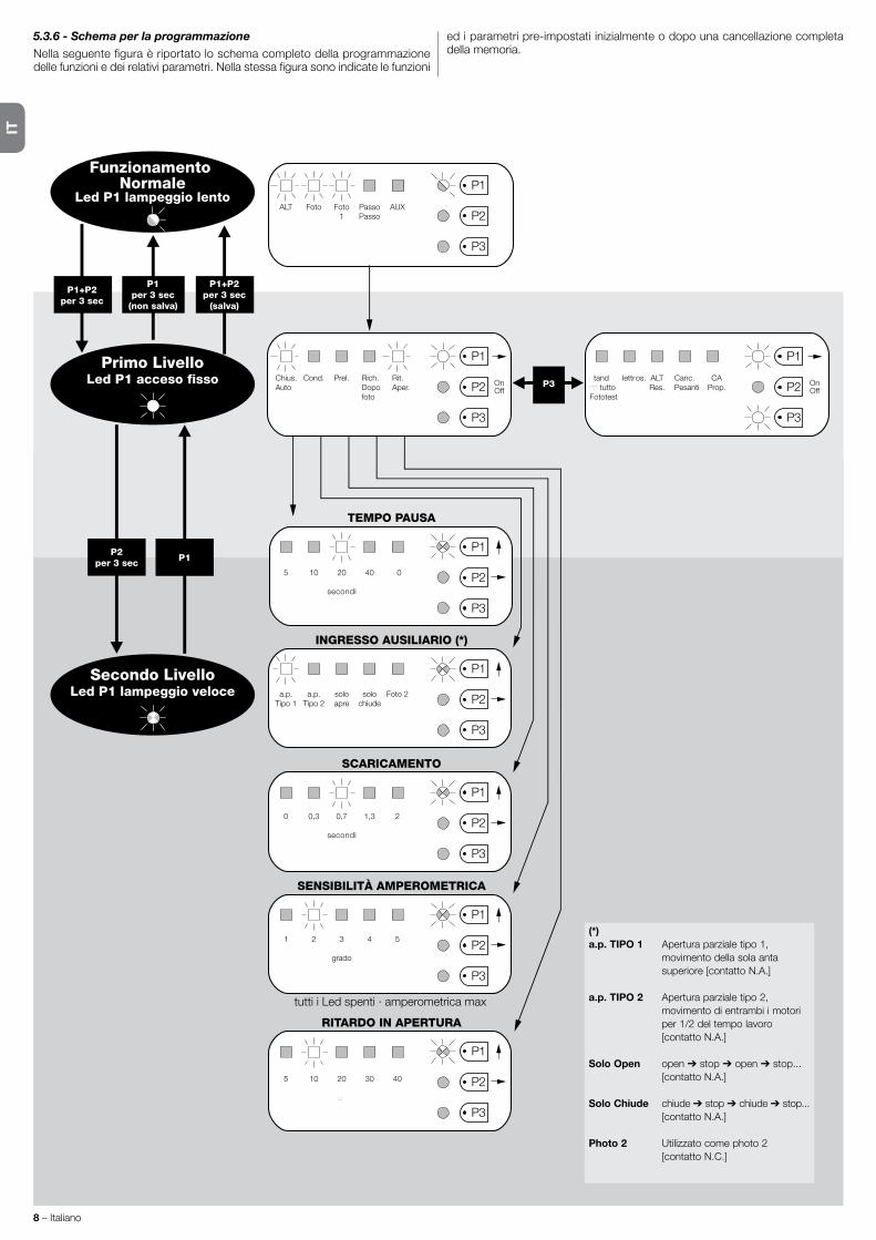
IT
8 – Italiano
5.3.6 - Schema per la programmazioneNellaseguentefiguraèriportatoloschemacompletodellaprogrammazionedellefunzioniedeirelativiparametri.Nellastessafigurasonoindicatelefunzioni
ed i parametri pre-impostati inizialmente o dopo una cancellazione completa della memoria.
ALT Foto Foto1
PassoPasso
AUX
Funzionamento Normale
Led P1 lampeggio lento
Primo LivelloLed P1 acceso fisso
Secondo LivelloLed P1 lampeggio veloce a.p.
Tipo 1a.p.
Tipo 2soloapre
solochiude
Foto 2
tutti i Led spenti · amperometrica max
P1+P2per 3 sec
P1per 3 sec
(non salva)
P1+P2per 3 sec
(salva)
Chius.Auto
Cond. Prel. Rich.Dopofoto
Rit.Aper. On
OffOnOff
INGRESSO AUSILIARIO (*)
SCARICAMENTO
0 0,3 0,7
secondi
1,3 2
SENSIBILITÀ AMPEROMETRICA
1 2 3
grado
4 5
RITARDO IN APERTURA
5 10 20
�
30 40
5 10 20
secondi
40 �0
TEMPO PAUSA
P1P2
per 3 sec
P1
P1
P2
P3
P1
P2
P3
P1
P2
P3
P1
P2
P3
P1
P2
P3
P1
P2
P3
P2
P3
�tand�� tuttoFototest
�lettros. ALTRes.
Canc.Pesanti
�CAProp.P3
P1
P2
P3
(*)a.p. TIPO 1 Aperturaparzialetipo1, movimento della sola anta superiore[contattoN.A.]
a.p. TIPO 2 Apertura parziale tipo 2, movimento di entrambi i motori per1/2deltempolavoro [contattoN.A.]
Solo Open open ➔ stop ➔ open ➔ stop... [contattoN.A.]
Solo Chiude chiude ➔ stop ➔ chiude ➔ stop... [contattoN.A.]
Photo 2 Utilizzato come photo 2 [contattoN.C.]
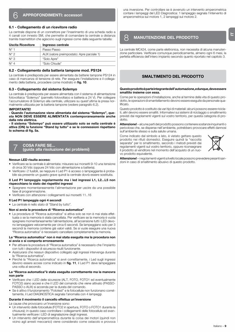
IT
Italiano – 9
6.1 - Collegamento di un ricevitore radioLa centrale dispone di un connettore per l’inserimento di una scheda radio a 4 canali con innesto SM, che permette di comandare la centrale a distanza tramite trasmettitori che agiscono sugli ingressi come dalla seguente tabella:
Uscita Ricevitore Ingresso centraleN°1 PassoPasso
N°2 AUX(valorepreimpostato:Apreparziale1)
N° 3 “Solo Apre”
N° 4 “Solo Chiude”
6.2 - Collegamento della batteria tampone mod. PS124LacentraleèpredispostaperesserealimentatadabatterietamponePS124incaso di mancanza di tensione di rete. Per eseguire l’installazione e il collega-mento della batteria, procedere come mostrato in fig. 10.
6.3 - Collegamento del sistema SolemyoLacentraleèpredispostaperesserealimentataconilsistemadialimentazionefotovoltaica“Solemyo”(pannellofotovoltaicoebatteriaa24V).Percollegarel’accumulatore di Solemyo alla centrale, utilizzare su quest’ultima la presa nor-malmenteutilizzataperlabatteriatampone(vedereparagrafo6.2).
IMPORTANTE!- Quando l’automazione viene alimentata dal sistema “Solemyo”, que-sta NON DEVE ESSERE ALIMENTATA contemporaneamente anche dalla rete elettrica.- Il sistema “Solemyo” può essere utilizzato solo se nella centrale è attiva (ON) la funzione “Stand by tutto” e se le connessioni rispettano lo schema di fig. 5a.
APPROFONDIMENTI: accessori6
Nessun LED risulta acceso:• Verificareselacentraleèalimentata:misuraresuimorsetti9-10unatensionedicirca30Vdc(oppure24Vdcconalimentazioneabatteria).
• Verificarei2fusibili,seneppureilLedP1èaccesoolampeggianteèproba-bile sia presente un guasto grave quindi la centrale dovrà essere sostituita.
Il Led P1 lampeggia regolarmente ma i led ingressi L1, L2...L5 non rispecchiano lo stato dei rispettivi ingressi• Spegnere momentaneamente l’alimentazione per uscire da una possibile
fase di programmazione.• Verificareconattenzioneicollegamentisuimorsetti11..16
Il Led P1 lampeggia ogni 4 secondi• Lacentraleènellostatodi“Standbytutto”.
Non si avvia la procedura di “Ricerca automatica”• Laproceduradi“Ricercaautomatica”siattivasolosenonèmaistataeffet-tuataoselamemoriaèstatacancellata.Perverificareselamemoriaèvuotaspegnere momentaneamente l’alimentazione, all’accensione tutti i LED devo-no lampeggiare velocemente per circa 6 secondi. Se lampeggiano solo per 3 secondi la memoria contiene già valori validi. Se si vuole eseguire una nuova “Ricercaautomatica”ènecessariocancellarecompletamentelamemoria.
La “Ricerca automatica” non è mai stata eseguita ma la procedura non si avvia o si comporta erroneamente• Perattivarelaproceduradi“Ricercaautomatica”ènecessariochel’impianto
con tutti i dispositivi di sicurezza risulti funzionante.• Assicurarsi che nessun dispositivo collegato agli ingressi intervenga durante
la “Ricerca automatica”.• Perché la “Ricerca automatica” si avvii correttamente, i Led sugli ingressi
devono essere accesi come indicato in fig. 11,ilLedP1develampeggiareuna volta al secondo.
La “Ricerca automatica”è stata eseguita correttamente ma la manovra non parte• VerificarecheiLEDdellesicurezze(ALT,FOTO,FOTO1edeventualmenteFOTO2)sianoaccesiecheilLEDdelcomandochevieneattivato(PASSO-PASSOoAUX)siaccendaperladuratadelcomando.
• Seèattivoilfunzionamento“Fototest”elefotocellulenonfunzionanocorret-tamente,ilLedDIAGNOSTICAsegnalal’anomaliacon4lampeggi.
Durante il movimento il cancello effettua un’inversioneLe cause che provocano un’inversione sono:• Uninterventodellefotocellule(FOTO2inapertura,FOTOoFOTO1durantelachiusura);inquestocasocontrollareicollegamentidellefotocelluleedeven-tualmenteverificareiLEDdisegnalazionedegliingressi.
• Un intervento dell’amperometrica durante la corsa dei motori (quindi non vicinoagliarrestimeccanici)vieneconsideratocomeostacoloeprovoca
COSA FARE SE...(guida alla risoluzione dei problemi)7
unainversione.PercontrollareseèavvenutouninterventoamperometricacontareilampeggidelLEDDiagnostica:1lampeggiosegnalal’interventodiamperometricasulmotore1,2lampeggisulmotore2.
MANUTENZIONE DEL PRODOTTO8La centrale MC424, come parte elettronica, non necessita di alcuna manuten-zioneparticolare.Verificarecomunqueperiodicamente,almenoogni6mesi,laperfettaefficienzadell’interoimpiantosecondoquantoriportatonelcapitolo3.
SMALTIMENTO DEL PRODOTTO
Questo prodotto è parte integrante dell’automazione, e dunque, deve essere smaltito insieme con essa.Come per le operazioni d’installazione, anche al termine della vita di questo pro-dotto, le operazioni di smantellamento devono essere eseguite da personale qua-lificato.
Questoprodottoècostituitodavaritipidimateriali:alcunipossonoesserericicla-ti, altri devono essere smaltiti. Informatevi sui sistemi di riciclaggio o smaltimento previsti dai regolamenti vigenti sul vostro territorio, per questa categoria di pro-dotto.
Attenzione! – alcune parti del prodotto possono contenere sostanze inquinanti o pericolose che, se disperse nell’ambiente, potrebbero provocare effetti dannosi sull’ambiente stesso e sulla salute umana.
Comeindicatodalsimboloalato,èvietatogettarequestoprodottonei rifiutidomestici.Eseguirequindi la“raccoltaseparata” per lo smaltimento, secondo i metodi previsti dai regolamenti vigenti sul vostro territorio, oppure riconsegnare il prodotto al venditore nel momento dell’acquisto di un nuo-vo prodotto equivalente.
Attenzione! – i regolamenti vigenti a livello locale possono prevedere pesanti san-zioni in caso di smaltimento abusivo di questo prodotto.

IT
10 – Italiano
AVVERTENZE:•Tuttelecaratteristichetecnicheriportate,sonoriferiteadunatemperaturaambientaledi20°C(±5°C).•NiceS.p.a.siriservaildirittodiappor-taremodifichealprodottoinqualsiasimomentoloriterrànecessario,mantenendonecomunquelastessafunzionalitàedestinazioned’uso.
Alimentazione di rete CentraleMC424: 230V~±10%50-60Hz CentraleMC424/V1: 120V~±10%50-60Hz
Potenza max assorbita 170W
Alimentazione di emergenza predispostaperbatterietamponePS124eperkitsolareSolemyo
Corrente massima motori 3A(conlivellointerventoamperometrica“grado6”)
Uscita alimentazione servizi 24V correntemassima200mA(latensionepuòvariareda16a33V )
Uscita fototest 24V correntemassima100mA(latensionepuòvariareda16a33V )
Uscita lampeggiante perlampeggianti24V ,potenzamassima25W(latensionepuòvariareda16a33V )
Uscita spia cancello perlampade24V potenzamassima5W(latensionepuòvariareda16a33V ) oppureelettroserrature12V~25W
Ingresso ALT percontattiNCoppureresistenzacostante8,2KΩ+/-25%
Tempo lavoro rilevato automaticamente
Tempo pausa programmabilea5,10,20,40,80secondi
Tempo scaricamento programmabilea0,0,3,0,7,1,3,2secondi
Ritardo anta in apertura programmabilea5,10,20,30e40%deltempolavoro
Ritardo anta in chiusura rilevato automaticamente
Uscita 1° motore permotoriWingoWG4024-WG5024
Uscita 2° motore permotoriWingoWG4024-WG5024Lunghezza max cavi alimentazione 30m alimentazione kit solare Solemyo 3 m motori 10m altriingressi/uscite 30m lampeggiante 10m SCA 30m elettroserratura 10m antenna 20m (consigliato minore di 3 m)
Ricevitore radio Innestotipo“SM”perricevitoriSMXI,SMXIS,OXI(ModoIeModoII)
Temperatura di esercizio da-20a50°C
Grado di protezione IP54acontenitoreintegro
Dimensioni (mm) 310x232xH122
Peso (kg) 4,1
CARATTERISTICHE TECNICHE DEL PRODOTTO
Dichiarazione CE di conformitàDichiarazione in accordo alle Direttive: 2004/108/CE (EMC); 2006/42/CE (MD) allegato II, parte B
Nota - Il contenuto di questa dichiarazione corrisponde a quanto dichiarato nel documento ufficiale depositato presso la sede di Nice S.p.a., e in particolare, alla sua ultima revisione disponibile prima della stampa di questo manuale . Il testo qui presente è stato riadattato per motivi editoriali . Copia della dichiarazione originale può essere richiesta a Nice S .p .a . (TV) I .
Numero:296/MC424 Revisione: 3 Lingua:IT
Nome produttore: Nice s.p.a.Indirizzo: ViaPezzaAlta13,Z.I.Rustignè,31046Oderzo(TV)ItalyPersona autorizzata a costituire la documentazione tecnica: Nice s.p.a.Tipo di prodotto: Centraledicomandoa2motori24Vd.c.Modello / Tipo: MC424Accessori: Ricevente radio SMX, SMXISI
Il sottoscritto Mauro Sordini in qualità di Amministratore Delegato, dichiara sotto la propria responsabilità che il prodotto sopra indicato risulta conforme alle disposizioni imposte dalle seguenti direttive:•DIRETTIVA2004/108/CEDELPARLAMENTOEUROPEOEDELCONSIGLIOdel15dicembre2004concernenteilravvicinamentodellelegislazionidegliStatimembrirelativeallacompatibilitàelettromagneticaecheabrogaladirettiva89/336/CEE,secondoleseguentinormearmonizzate:EN61000-6-2:2005,EN61000-6-3:2007+A1:2011
Inoltre il prodotto risulta essere conforme alla seguente direttiva secondo i requisiti previsti per le “quasi macchine”: Direttiva2006/42/CEDELPARLAMENTOEUROPEOEDELCONSIGLIOdel17maggio2006relativaallemacchineechemodificaladirettiva95/16/CE(rifusione)•Sidichiaracheladocumentazionetecnicapertinenteèstatacompilatainconformitàall’allegatoVIIBdelladirettiva2006/42/CEechesonostatirispettatiiseguentirequisitiessenziali:1.1-1.1.2-1.1.3-1.2.1-1.2.6-1.5.1-1.5.2-1.5.5-1.5.6-1.5.7-1.5.8-1.5.10-1.5.11• Il produttore si impegna a trasmettere alle autorità nazionali, in risposta ad una motivata richiesta, le informazioni pertinenti sulla “quasi macchina”, mantenendo impregiudicati i propri diritti di proprietà intellettuale. •Qualorala“quasimacchina”siamessainservizioinunpaeseeuropeoconlinguaufficialediversadaquellausatanellapresentedichiarazione,l’importatorehal’obbligodiasso-ciare alla presente dichiarazione la relativa traduzione.•Siavvertechela“quasimacchina”nondovràesseremessainserviziofinchélamacchinafinaleincuisaràincorporatanonsaràasuavoltadichiarataconforme,sedelcaso,alledisposizionidelladirettiva2006/42/CE.
Inoltre il prodotto risulta conforme alle seguenti norme:EN60335-1:2002+A1:2004+A11:2004+A12:2006+A2:2006+A13:2008+A14:2010+A15:2011,EN60335-2-103:2003+A11:2009
Il prodotto risulta conforme, limitatamente alle parti applicabili, alle seguenti norme:EN13241-1:2003+A1:2011,EN12445:2002,EN12453:2002,EN12978:2003+A1:2009
Oderzo,30luglio2014 Ing.MauroSordini(AmministratoreDelegato)

IT
Italiano – 11
SMXI, SMXIS sono ricevitori radio a 4 canali per centrali dotate dell’inesto SM. I trasmettitori compatibili hanno la particolarità che il codice di riconoscimento risulta diverso per ogni trasmettitore. Quindi per permettere al ricevitore di rico-noscere un determinato trasmettitore occorre procedere alla memorizzazione del codice di riconoscimento. Questa operazione di inserimento va ripetuta per ogni trasmettitore che si voglia utilizzare per comandare la centrale.
Note:– Nel ricevitore posso essere memorizzati fino ad un massimo di 256 trasmet titori . Non è prevista la cancellazione di un singolo trasmettitore ma solo la can-cellazione totale di tutti i codici .– Per funzioni più avanzate utilizzare l’apposita unità di programmazione .
DESCRIZIONE DEL PRODOTTO1Ilricevitoredisponedi4usciteTuttedisponibilisulconnettoresottostante,persaperequalefunzioneèsvoltadaogniuscitavederecapitolo6.1.
Nellafasedimemorizzazionedelcodicedeltrasmettitoreèpossibilesceglieretra queste 2 opzioni:
Modo I - Tabella B1: ogni tasto del trasmettitore attiva la corrisponde uscita nelricevitore,cioèiltasto1attival’uscita1,iltasto2attival’uscita2,ecosìvia.Inquestocasoc’èun’unicafasedimemorizzazioneperognitrasmettitore,durante questa fase non ha importanza quale tasto viene premuto, e viene occupato un solo posto in memoria.
Modo II - Tabella B2: ad ogni tasto del trasmettitore può essere associata unaparticolareuscitadelricevitore,esempioiltasto1attival’uscita2,iltasto2attival’uscita1,eccetera.Inquestocasobisognamemorizzareiltrasmettitore,premendo il tasto desiderato, per ogni uscita da attivare. Naturalmente ogni tasto può attivare una sola uscita, mentre la stessa uscita può essere attivata dapiùtasti.Vieneoccupatounpostoinmemoriaperognitasto.
TABELLA B1 - Memorizzazione modo I (tutti i tasti vengono memorizzati sulla rispettiva uscita della ricevente)
01. Premere e tenere premuto il pulsante sul ricevitore per almeno 3 secondi
02. Quando il Led si accende, rilasciare il pulsante
03. Entro10secondipremereperalmeno2secondiunqualsiasitastodeltrasmettitoredamemorizzare
Nota – se la memorizzazione è andata a buon fine il Led sul ricevitore farà 3 lampeggi se ci sono altri trasmettitori da memorizzare, ripetere il passo 3 entro altri 10 secondi la fase di memorizzazione termina se per 10 secondi non vengono ricevuti nuovi codici
INSTALLAZIONE ANTENNA2Per ottenere un buon funzionamento il ricevitore necessita di un’antenna di tipo ABFoABFKIT;senzaantennalaportatasiriduceapochimetri.L’antennadeveessereinstallatapiùinaltopossibile;inpresenzadistrutturemetallicheodicemento armato, installare l’antenna al di sopra di queste. Se il cavo in dotazio-neall’antennaètroppocorto,impiegarecavocoassialeconimpedenza50ohm(es.RG58abassaperdita),ilcavonondevesuperarelalunghezzadi10m.Qualora l’antenna installata dove non ci sia un buon piano di terra (strutture murarie)èpossibilecollegareilmorsettodellacalzaaterraottenendocosìunamaggiore portata. Naturalmente la presa di terra deve essere nelle vicinanze e di buona qualità. Nel caso non sia possibile installare l’antenna accordata ABF oABFKITsipossonootteneredeidiscretirisultatiusandocomeantennalospezzonedifilofornitocolricevitore,montatodisteso.
ATTENZIONE – Quando si attiva la fase di memorizzazione, qualsiasi trasmettitore correttamente riconosciuto nel raggio di ricezione del-la radio viene memorizzato. Valutare con attenzione questo aspetto, eventualmente staccare l’antenna per ridurre la capacità del ricevitore.Le procedure per la memorizzazione dei telecomandi hanno un tempo limite
MEMORIZZAZIONE DI UN TELECOMANDO3
peressereeseguite;ènecessarioquindileggereecomprenderetuttalaproce-dura prima di iniziare le operazioni.Pereseguirelaproceduraseguente,ènecessarioutilizzareilpulsantepresen-te sul box del ricevitore radio (riferimento A, fig. 1a)edilrispettivoLed(riferi-mento B, fig. 1a)allasinistradeltasto.
1a
TABELLA B2 - Memorizzazione modo II (ad ogni tasto può essere associata una particolare uscita della ricevente)
01. Premere e rilasciare il pulsante sul ricevitore un numero di volte uguale all’uscita desiderata (1voltaperuscitan°1,2volteperuscitan°2)
02. VerificarecheilLedemetteunnumerodilampeggiugualiall’uscitavoluta,ripetutiacadenzaregolarenei10sec. (1lampeggioseuscitan°1,2lampeggiseuscitan°2)
03. Entro10secondipremereperalmeno2secondiiltastodesideratodeltrasmettitoredamemorizzare
Nota – se la memorizzazione è andata a buon fine il Led sul ricevitore farà 3 lampeggi se ci sono altri trasmettitori da memorizzare, ripetere il passo 3 entro altri 10 secondi la fase di memorizzazione termina se per 10 secondi non vengono ricevuti nuovi codici
3sRX
TX
RX
2s
x3
2s
x3
RX
TX
smxi - smxis ricevitore radio0682

IT
12 – Italiano
Memorizzazione a distanzaÈ possibile memorizzare un nuovo trasmettitore nella memoria del ricevitore senza agire direttamente sul tastino. È necessario disporre di un telecomando già memorizzato e funzionante. Il nuovo trasmettitore “erediterà” le caratteristi-chediquellogiàmemorizzato.Quindiseilprimotrasmettitoreèmemorizzatoinmodo I anche il nuovo sarà memorizzato in modo I e si potranno premere uno qualunquedeitastideitrasmettitori.Seilprimotrasmettitoreèmemorizzatoin
modo II anche il nuovo sarà memorizzato in modo II ma occorre premere, nel primo trasmettitore il tasto che attiva l’uscita desiderata, e nel secondo tra-smettitore il tasto che si vuol memorizzare. È necessario leggere tutte le istru-zioniperpoieseguireleoperazioniunadopol’altrasenzainterruzioni.OraconiduetelecomandichechiameremoNUOVOquelloconilcodicedainserire,eVECCHIOquellogiàmemorizzato,porsinelraggiodiazionedeiradiocomandi(entrolaportatamassima)edeseguireipassiriportatiintabella.
TABELLA B4 - Cancellazione di tutti i trasmettitori
01. Premere e tenere premuto il pulsante sul ricevitore
02. Aspettare che il Led si accenda, poi aspettare che si spenga, quindi aspettare che emetta 3 lampeggi
03. Rilasciare il tasto esattamente durante il 3° lampeggio
Nota – se a procedura è andata a buon fine, dopo qualche istante, il Led emetterà 5 lampeggi
È possibile cancellare tutti i codici presenti in memoria con la seguente procedura:
CANCELLAZIONE DI TUTTI I TRASMETTITORI4
CARATTERISTICHE TECNICHE DEL PRODOTTO
Ricevitori: SMXI SMXISDecodifica Rolling code a52bitFLOR Rollingcode a64bitSMILOCompatibilità trasmettitori FLOR,VERYVR,NICEWAY,ERGO,PLANO,NICEONE SMILO
Frequenza 433.92 MHz 433.92 MHz
Impedenza di ingresso 52KΩ 52KΩUscite 4(suconnettoreSM) 4(suconnettoreSM)
Sensibilità miglioredi0.5µV miglioredi0.5µV
Temperatura di funzionamento da -10°Ca+55°C da -10°Ca+55°C
Trasmettitori: FLO2R SMILOTasti 1,2oppure4asecondadelleversioni 2oppure4
Alimentazione 12V Batt.23A 12V Batt. 23 A
Assorbimento 10mA 25mA
Frequenza di trasmissione 433.92 MHz 433.92 MHz
Temp. di funzionamento da -10°Ca+55°C a -10°Ca+55°C
Potenza irradiata stimatacirca1mWE.R.P. stimatacirca1mWE.R.P.
Portata stimata200m(all’esterno);35m(seall’internodiedifici) stimata200m(all’esterno);35m(seall’internodiedifici)
Dimensioni / Peso 69x39x15,5mm/31g. Ø48mmxH14mm-14g
Codifica digitale(4,5milionidimiliardidicombinazioni) digitale(18miliardidimiliardidicombinazioni)
AVVERTENZE:•Tuttelecaratteristichetecnicheriportate,sonoriferiteadunatemperaturaambientaledi20°C(±5°C).•NiceS.p.a.siriservaildirittodiappor-taremodifichealprodottoinqualsiasimomentoloriterrànecessario,mantenendonecomunquelastessafunzionalitàedestinazioned’uso.•Laportatadeitra-smettitori e la capacità di ricezione dei Ricevitori può essere soggetta ad interferenze che ne possono alterare le prestazioni. Nei casi di queste interferenze, Nice non può offrire nessuna garanzia circa la reale portata dei propri dispositivi.
TABELLA B3 - Memorizzazione a distanza
01. Premereperalmeno5secondiiltastosulNUOVOtrasmettitore,poirilasciare
02. Premerelentamenteper3volteiltastosulVECCHIOtrasmettitore
03. Premerelentamenteper1voltailtastosulNUOVOtrasmettitore,poirilasciare
Nota – se ci sono altri trasmettitori da memorizzare, ripetere tutti i passi per ogni nuovo trasmettitore
1s
x1
TX
TX TX TX
TX
TX
1s1s
x5s
RX
RX
x3
3°
x5

FR
Français – 1
FRANÇAIS
Recommandations pour la sécurité• ATTENTION ! – Ce guide contient des instructions et des recomman-
dations importantes pour la sécurité des personnes. Une installation erronée peut causer de graves blessures. Avant de procéder à l’installation, il faut lire attentivement toutes les parties du guide. En cas de doutes, suspendre l’installation et demander des éclaircissements au Service Assistance Nice.
• ATTENTION ! – Instructions importantes : conserver avec soin ce guide pour faciliter les éventuelles interventions futures de mainte-nance ou de mise au rebut du produit.
Avertissements pour l’installation•Avantdecommencerl’installation,vérifiersileprésentproduitestadaptéautyped’utilisationdésirée(voirparagraphe2.2« Limitesd’utilisation »etchapitre« Caractéristiquestechniquesduproduit »).S’iln’estpasadapté,NE PAS procéder à l’installation.
• Au cours de l’installation, manipuler le produit avec précaution en évitant les écrasements, les chocs, les chutes ou le contact avec des liquides de n’im-porte quelle nature. Ne pas mettre le produit à proximité de fortes sources dechaleurni l’exposeràdesflammesvives.Toutescesactionspeuventl’endommageretcauserdesproblèmesdefonctionnementoudessitua-tions de danger. Si cela se produit, suspendre immédiatement l’installation et s’adresserauserviceaprès-venteNice.
•Nepaseffectuerdemodificationssurunepartiequelconqueduproduit.Lesopérationsnonautoriséesnepeuventqueprovoquerdesproblèmesdefonctionnement. Le constructeur décline toute responsabilité pour les dom-magesdérivantdemodificationsarbitrairesauproduit.
• Le produit n’est pas destiné à être utilisé par des personnes (enfants com-pris)auxcapacitésphysiques,sensoriellesoumentalesréduites,ouman-quant d’expérience ou de connaissances, à moins que celles-ci aient pu bénéficier,parl’intermédiaired’unepersonneresponsabledeleursécurité,d’une surveillance ou d’instructions sur l’utilisation du produit.
• Ne pas laisser les enfants jouer avec les dispositifs de commande de l’auto-matisme. Conserver les émetteurs hors de portée des enfants.
• Les enfants doivent être surveillés pour s’assurer qu’ils ne jouent pas avec l’appareil.
• Prévoir, sur la ligne d’alimentation de l’installation, un dispositif de déconne-xion avec une distance d’ouverture des contacts permettant la déconnexion complètedanslesconditionsprescritesparlacatégoriedesurtensionIII.
• La logique de commande doit être connectée à une ligne d’alimentation élec-trique avec mise à la terre.
• Les matériaux de l’emballage du produit doivent être mis au rebut dans le plein respect des normes locales en vigueur.
RECOMMANDATIONS ET PRÉCAUTIONSGÉNÉRALES
La logique de commande MC424 est destinée à la commande d’opérateurs électromécaniquesWingoà24V,pourl’automatisationdeportesouportailsbattants. ATTENTION ! - Toute autre utilisation que celle décrite et dans des conditions ambiantes différentes de celles indiquées dans ce guide doit être considérée comme impropre et interdite !La logiquedecommandeMC424disposed’unsystèmequivérifie l’effortdesmoteursqui luisontconnectés(ampèremétrique) ;cesystèmepermetdedétecterautomatiquementlesfinsdecourse,demémoriserletempsdetravail de chaque moteur et de reconnaître les éventuels obstacles au cours d’une manœuvre normale. Cette caractéristique facilite l’installation vu qu’il n’y a besoin d’aucun réglage des temps de travail et de décalage des vantaux.La logique de commande est préprogrammée sur les fonctions normalement demandées ;éventuellement,àtraversunesimpleprocédure,onpeutchoisirdesfonctionsplusspécifiques(voirchapitre5).La logique de commande est prévue pour être alimentées par des batteries tamponPS124commealimentationdesecours,encasdecoupuredelaten-siondesecteur(pourtoutdétailvoirchapitre6.2) ;elleestprévueégalementpourêtreconnectéeausystèmed’alimentationàénergiesolaire« Solemyo »(pourtoutdétailvoirchapitre6.3).
DESCRIPTION DU PRODUIT1
Pour préciser certains termes et certains aspects d’une installation d’automa-tisation de portes ou portails à 2 battants, se référer à l’installation typique illustrée fig. 1.
Légende fig. 1 :1.OpérateurélectromécaniqueWingoà24V2.OpérateurélectromécaniqueWingoà24V
INSTALLATION2
Sommaire AVERTISSEMENTS ET PRÉCAUTIONS GÉNÉRALES . . . . . . . . . . 1
1 – DESCRIPTION DU PRODUIT . . . . . . . . . . . . . . . . . . . . . . . . . . . . . . 1
2 – INSTALLATION . . . . . . . . . . . . . . . . . . . . . . . . . . . . . . . . . . . . . . . . . . 1
2.1 - CONTRÔLES AVANT L’INSTALLATION . . . . . . . . . . . . . . . . . 2
2.2 - LIMITES D’UTILISATION DU PRODUIT . . . . . . . . . . . . . . . . . 2
2.3 - INSTALLATION . . . . . . . . . . . . . . . . . . . . . . . . . . . . . . . . . . . . . 2
2.4 - CONNEXIONS ÉLECTRIQUES . . . . . . . . . . . . . . . . . . . . . . . . . 2 2.4.1 - Notes sur les connexions . . . . . . . . . . . . . . . . . . . . . . . 3 2.4.2 - Typologie d’entrée HALTE . . . . . . . . . . . . . . . . . . . . . . 3 2.4.3 - Exemples de connexions photocellules : avec la fonction « Stand-by total » active et la fonction phototest désactive . . . . . . . . . . . . . . . . . . . . . . . . . . . 3 2.4.4 - Exemples de connexions photocellules : avec la fonction phototest active et la fonction « Stand-by total » désactivée . . . . . . . . . . . . . . . . . . . . 3
2.5 - PREMIÈRE MISE EN SERVICE ET VÉRIFICATION DES CONNEXIONSI . . . . . . . . . . . . . . . . . . . . . . . . . . . . . . . . . 3
2.6 - RECHERCHE AUTOMATIQUE DES FINS DE COURSE . . . . . 3
3 – ESSAI ET MISE EN SERVICE . . . . . . . . . . . . . . . . . . . . . . . . . . . . . . 4
3.1 - ESSAI . . . . . . . . . . . . . . . . . . . . . . . . . . . . . . . . . . . . . . . . . . . . . 4
3.2 - MISE EN SERVICE . . . . . . . . . . . . . . . . . . . . . . . . . . . . . . . . . . 4
4 – DIAGNOSTIC . . . . . . . . . . . . . . . . . . . . . . . . . . . . . . . . . . . . . . . . . . . 4
5 – PROGRAMMATION . . . . . . . . . . . . . . . . . . . . . . . . . . . . . . . . . . . . . . 4
5.1 - FONCTIONS PRÉPROGRAMMÉES . . . . . . . . . . . . . . . . . . . . . 5
5.2 - FONCTIONS PROGRAMMABLES . . . . . . . . . . . . . . . . . . . . . . 5 5.2.1 - Programmation directe . . . . . . . . . . . . . . . . . . . . . . . . . 5 5.2.2 - Programmation de premier niveau : première partie 5 5.2.3 - Programmation de premier niveau : deuxième partie 5 5.2.4 - Fonctions de deuxième niveau . . . . . . . . . . . . . . . . . . 5
5.3 - MODALITÉS DE PROGRAMMATION . . . . . . . . . . . . . . . . . . . 5 5.3.1 - Programmation de premier niveau : fonctions . . . . . . 6 5.3.2 - Programmation de deuxième niveau : paramètres . . 6 5.3.3 - Effacement de la mémoire . . . . . . . . . . . . . . . . . . . . . . 7 5.3.4 - Exemple de programmation de premier niveauo . . . . 7 5.3.5 - Exemple de programmation de deuxième niveau . . . 7 5.3.6 - Schéma pour la programmation . . . . . . . . . . . . . . . . . 8
6 – APPROFONDISSEMENTS : accessoires . . . . . . . . . . . . . . . . . . . . . 9
6.1 - CONNEXION D’UN RÉCEPTEUR RADIO . . . . . . . . . . . . . . . . 9
6.2 - CONNEXION DE LA BATTERIE TAMPON MOD. PS1244 . . . 9
6.3 - CONNEXION DU SYSTÈME SOLEMYO . . . . . . . . . . . . . . . . . 9
7 – QUE FAIRE SI…(guide en cas de problèmes) . . . . . . . . . . . . . . . . . 9
8 – MAINTENANCE DU PRODUIT . . . . . . . . . . . . . . . . . . . . . . . . . . . . . 9
MISE AU REBUT DU PRODUIT . . . . . . . . . . . . . . . . . . . . . . . . . . . . 9
CARACTÉRISTIQUES TECHNIQUES DU PRODUIT . . . . . . . . . . . 10
CE DÉCLARATION DE CONFORMITÉ . . . . . . . . . . . . . . . . . . . . . . 10
RÉCEPTEUR RADIO : SMXI - SMXIS . . . . . . . . . . . . . . . . . . . . . . . 11
1 - DESCRIPTION DU PRODUIT . . . . . . . . . . . . . . . . . . . . . . . . . . 11 2 - INSTALLATION ANTENNE . . . . . . . . . . . . . . . . . . . . . . . . . . . . 11 3 - MÉMORISATION D’UN ÉMETTEUR . . . . . . . . . . . . . . . . . . . . . 11 4 - EFFACEMENT DE TOUS LES ÉMETTEURS . . . . . . . . . . . . . . 12
CARACTÉRISTIQUES TECHNIQUES DU PRODUIT . . . . . . . . . . . 12
IMAGES . . . . . . . . . . . . . . . . . . . . . . . . . . . . . . . . . . . . . . . . . . . . . I-V
Instructions originales

FR
2 – Français
3. Clignotant Lucy244. Sélecteur à clé5. Pairedephotocellules« PHOTO »6.Pairedephotocellules« PHOTO1 »7. Pairedephotocellules« PHOTO2 »8. Logique de commande
Enparticuliernousrappelonsque :• Pour les caractéristiques et la connexion des photocellules se référer aux instructionsspécifiquesduproduit.
•L’interventiondelapairedephotocellules« PHOTO »enouverturen’apasd’effet tandis qu’elle provoque une inversion durant la fermeture.
•L’interventiondelapairedephotocellules« PHOTO1 »bloquelamanœuvreaussi bien en ouverture qu’en fermeture.
•L’interventiondelapairedephotocellules« PHOTO2 »(connectéeàl’entréeAUXopportunémentprogrammée)enfermeturen’apasd’effettandisqu’elleprovoque une inversion durant l’ouverture.
Pourvérifierlespartiesdelalogiquedecommande,voirfig. 2.
Légende fig. 2 :A. Connecteuralimentation24VB. ConnecteurmoteurM1C. ConnecteurpourbatterietamponPS124/systèmed’alimentation
àénergiesolaireSolemyo(pourtoutdétailvoirchapitre6.3)D. Fusibleservices(500mA)typeFE. SélecteurretardouverturemoteurM1ouM2F. Borne moteur M2G. Borne sortie clignotantH. BornesortieSCA(voyantportailouvert)ouserrureélectriqueI. Bornes24VccpourservicesetphototestL. Bornes pour entrées L1…L5. Leds entrées et programmationM. Borne pour antenne radioN. Connecteur« SM »pourrécepteurradioO. Connecteurpourprogrammation/diagnosticP1, P2, P3. Touchesetledspourprogrammation
2.1 - Contrôles avant l’installationAvantd’effectuerl’installation,ilestnécessairedevérifierl’intégritédescompo-santsduproduit,l’adéquationdumodèlechoisietsonadaptationaulieuprévupoursoninstallation :•Vérifierquetouteslesconditionsd’applicationrentrentdansles« limitesd’uti-lisation »etdansles« caractéristiquestechniques »duproduit.•Vérifierquel’environnementchoisipour l’installationestcompatibleavecl’encombrement total du produit (fig. 3).•Vérifierquelasurfacechoisiepourl’installationduproduitestsolideetpeutgarantirunefixationstable.•Vérifierquelazonedefixationn’estpassujetteàinondation ;prévoirlemon-tageduproduitàunehauteursuffisanteparrapportausol.•Vérifierquel’espaceautourduproduitpermetuneexécutionfacileetsûredes manœuvres manuelles.•Vérifierlaprésencedebutéesmécaniquesdansl’installationaussibienenFermeturequ’enOuverture.
2.2 - Limites d’utilisation du produitLe présent produit peut être utilisé exclusivement avec les opérateurs WG4024,WG5024,XME2024,TN2020,TN2020L,TOO3024,TOO4524.
2.3 - InstallationPourlafixationdelaLogique,procédercommeindiquéfig. 4. Par ailleurs, respecterlesconsignessuivantes :• La logique de commande est fournie dans un boîtier qui, s’il est correctement installé,garantitunindicedeprotectionIP54.Parconséquent,lalogiquedecommande est adaptée pour être installée aussi à l’extérieur.• Fixer la logique de commande sur une surface inamovible, verticale, plate et à l’abri du risque de chocs. Attention ! – La partie inférieure de la logique doit setrouveràaumoins40cmaudessusdusol.• Monter les passe-câbles ou les passe-gaines dans la partie inférieure du boî-tier(fig.4).Attention ! – Si les gaines de protection des câbles aboutissent à un puisard, il est probable que de la condensation se formera à l’intérieur du boîtier de la logique en endommageant par conséquent la carte électro-nique.Danscecas,protégerlalogiquedecommandedemanièreadéquateafind’empêcherlaformationdecondensation.•Onpeutmonterlespasse-câblessurlecôtélongduboîtieruniquementsilalogique de commande est installée à l’intérieur, dans un endroit protégé.Pour effectuer l’installation des autres dispositifs présents dans l’automatisme, se référer aux guides d’instructions respectives.
2.4 - Connexions électriquesATTENTION !
– Toutes les connexions électriques doivent être effectuées en l’ab-sence d’alimentation de secteur et avec la batterie tampon déconnec-tée si elle est présente dans l’installation.– Les opérations de branchement doivent être effectuées exclusive-ment par du personnel qualifié.– Vérifier que tous les câbles électriques à utiliser sont du type adapté.01. Dévisserlesvisducouvercle ;02. Préparerlestrouspourlepassagedescâblesélectriques ;03. Procéder à la connexion des câbles en se référant au schéma électrique
de la fig. 5. Pour connecter le câble de l’alimentation électrique, voir fig. 6. Note – Pour faciliter les connexions des câbles, on peut extraire les bornes
de leur logement .• LesentréesdescontactsdetypeNF(NormalementFermé),siellesnesontpasutilisées,doiventêtreshuntéesavec« COMMUN »(àl’exclusiondesentréesdesphotocellulessilafonctionPHOTOTESTestactivée,pourtoutdétailvoirleparagraphe2.4.3).
• S’il y a plusieurs contacts NF pour la même entrée, ils doivent être mis en SÉRIE entre eux.
• LesentréesdescontactsdetypeNO(NormalementOuvert),siellesnesontpas utilisées, doivent être laissées libres.
• S’ilyaplusieurscontactsNOpourlamêmeentrée,ilsdoiventêtremisenPARALLÈLE entre eux.
• Les contacts doivent absolument être de type électromécanique et libres detoutpotentiel,lesconnexionsàétagestype« PNP »,« NPN »,« OpenCollector »etc.nesontpasadmises.
• En cas de vantail superposé, à l’aide du cavalier E (fig. 2)ilestpossibledesélectionner quel moteur doit démarrer en premier en ouverture.
Légende des fig. 2 - 5a - 5b - 5c: Bornes Fonction Description Type de câble
L - N - Ligne d’alim. Alimentation de secteur 3x1,5mm2
1÷3 Moteur1 ConnexiondumoteurM1 3x1,5mm2
1÷3 Moteur 2 ConnexiondumoteurM2(Note1) 3x1,5mm2
4÷5 Clignotant Connexionduclignotant24V max25W 2x1mm2
6÷7 SCA/Serrureélectrique ConnexionpourVoyantPortailOuvert24V max.5WouSerrureélectrique12Vmax.25VA(voirchapitre5-Programmation)
SCA:2x0,5mm2 Serrureélectrique:2x1mm2
8 Commun24V (avec Stand-bytotal/phototest)
Alimentazione+24V perTXfotocelluleconfototest(max100mA);«COMMUN»pourtouteslesentréesdesécurité,avecfonction«Stand-bytotal»active(Note2)
1x0,5mm2
9 0V Alimentation0V pour services 1x0,5mm2
10 24V Alimentationservices,sans« Stand-bytotal »(24Vmax.200mA) 1x0,5mm2
11 Comune24V Communpourtouteslesentrées(+24V )sans« Stand-bytotal » 1x0,5mm2
12 HALTE EntréeavecfonctiondeSTOP(urgence,blocagedesécurité)(Note3) 1x0,5mm2
13 PHOTO EntréeNFpourdispositifsdesécurité(photocellules,bordssensibles) 1x0,5mm2
14 PHOTO1 EntréeNFpourdispositifsdesécurité(photocellules,bordssensibles) 1x0,5mm2
15 PAS À PAS Entréepourfonctionnementcyclique(OUVRE-STOP-FERME-STOP) 1x0,5mm2
16 AUX Entréeauxiliaire(Note4)17÷18 Antenne Connexion antenne du récepteur radio
Note 1 – Non utilisée pour portails à un seul battant (la logique de commande reconnaît automatiquement s’il n’y a qu’un seul moteur installé)Note 2 – La fonction « Stand-by total » sert à réduire les consommations ; pour tout détail sur les connexions électriques voir paragraphe 2.4.1 « Connexion Stand-by total/Phototest » et pour la programmation voir chapitre 5.2.3 « Fonction Stand-by total/Phototest »Note 3 – L’entrée HALTE peut être utilisée pour des contacts NF ou à résistance constante 8,2 kΩ (voir chapitre « Programmation »)Note 4 – L’entrée auxiliaire AUX est programmée en usine avec la fonction « Ouverture partielle type 1 », mais elle peut être programmée avec l’une des fonc-tions suivantes :Fonction Type d’entrée DescriptionOUVERTUREPARTIELLETYPE1 NO Levantailsupérieurs’ouvrecomplètement

FR
Français – 3
2.4.1 - Notes sur les connexionsLa plupart des connexions sont extrêmement simples, une bonne partie d’entre elles sont des connexions directes à une unique utilisation ou à un seul contact. Lesfiguresci-aprèsdonnentquelquesexemplessurcommentconnecterlesdispositifsextérieurs :
• Connexion Stand-by total / PhototestLafonctionStand-byestactivedesérie ;elleestexclueautomatiquementunique-ment quand on désire activer la fonction Phototest. Note - Les fonctions « Stand-by total » et Phototest sont alternatives, dans la mesure où l’une exclut l’autre.La fonction permet de réduire la consommation d’énergie on peut obtenir trois typesdeconnexions :-avec« Stand-bytotal »actif(économie d’énergie) ;voirschémaélectrique
fig. 5a-connexionstandard :sans« Stand-bytotal »etsans« phototest »;voirsché-
ma électrique fig. 5b-sans« Stand-bytotal »etavec« phototest » ;voirschémaélectriquefig. 5cAveclafonction« Stand-bytotal »active,1minuteaprèslafind’unemanœuvre,lalogiquedecommandeentreen« Stand-bytotal »,enéteignanttouteslesEntrées et les Sorties pour réduire la consommation d’énergie. L’état est signa-léparlaled« OK »quicommenceàclignoterpluslentement.AVERTISSE-MENT - Si la logique de commande est alimentée par un panneau photovol-taïque(système« Solemyo »)ouunebatterietampon,ilfautactiverlafonction« Stand-bytotal »conformémentauschémaélectriquefig. 5a.Quandlafonction« Stand-bytotal »n’estpasutilisée,onpeutactiverlafonc-tion« Phototest »quipermetdevérifier,audébutd’unemanœuvre,lefonc-tionnement correct des photocellules connectées. Pour utiliser cette fonction, il faut d’abord connecter correctement les photocellules (voir schéma électrique fig. 5c)puisactiverlafonction.Note – En activant le phototest, les entrées sujettes à la procédure de test sont PHOTO, PHOTO1 et PHOTO2 . Si l’une de ces entrées n’est pas utilisée, il faut la connecter à la borne n° 8 .
• Connexion Sélecteur à cléExemple 1 (fig. 7a) : Comment connecter le sélecteur pour effectuer les fonc-tionsPASÀPASetHALTEExemple 2 (fig. 7b) : Comment connecter le sélecteur pour effectuer les fonc-tionsPASÀPASetl’unedecellesprévuesparl’entréeauxiliaire(OUVERTUREPARTIELLE,SEULEMENTOUVERTURE,SEULEMENTFERMETURE…)Note – Pour les connexions électriques avec la fonction « Stand-by total » active, voir « Fonction Stand-by total/Phototest » dans ce paragraphe 2.4.1.
• Connexion Voyant Portail Ouvert / Serrure électrique (fig. 8)Sielleestprogramméecomme« S.C.A. »,lasortiepeutêtreutiliséecommevoyant portail ouvert. Le voyant clignote lentement en ouverture tandis qu’en fermetureilclignoterapidement ;ilrestealluméfixequandleportailestouvertà l’arrêt et éteint avec le portail fermé. Si la sortie est programmée comme serrure électrique, elle est activée pendant 3 secondes à chaque début de ma nœuvre d’ouverture.
2.4.2 - Typologie d’entrée HALTELa logique de commande MC424 peut être programmée pour deux typologies d’entréeHALTE :- Halte type NF pour connexion à des contacts type NF.- Halte à résistance constante. Elle permet de connecter à la logique des dispositifsavecsortieàrésistanceconstante8,2kΩ(ex.bordssensibles).L’entrée mesure la valeur de la résistance et nie l’accord à la manœuvre quand la résistance sort des limites de la valeur nominale. En prenant cer-taines dispositions, il est possible de connecter à l’entrée halte à résistance constante également des dispositifs avec contacts normalement ouverts « NO »normalementfermés« NF »etéventuellementplusd’undispositif,mêmedetypedifférent ;VoirTableau1.
ATTENTION ! – Si l’entrée Halte à résistance constante est utilisée pour connecter des dispositifs avec fonctions de sécurité, seuls les disposi-tifs avec sortie à résistance constante 8,2 kΩ garantissent la catégorie 3 de sécurité aux pannes.
1er dispositif type:
NO NF 8,2KΩ
NO Enparallèle (note 1) (note 2) Enparallèle
NF (note 2) En série (note 3) En série
8,2KΩ Enparallèle En série (note 4)
TABLEAU 1
2e di
spos
itif t
ype:
Notes sur le Tableau 1 :Note 1 – Un ou plusieurs dispositifs NO peuvent être connectés en parallèle entre eux sans aucune limite de quantité avec une résistance terminale de 8,2 kΩ (fig. 9a). Pour les connexions électriques avec la fonction « Stand-by total »
active, voir « Fonction Stand-by total/Phototest » dans ce paragraphe 2.4.1.Note 2 – Il est possible de combiner NO et NF en mettant les deux contacts en parallèle, en prenant la précaution de mettre en série au contact NF une résistance de 8,2 kΩ (il est donc possible de combiner 3 dispositifs : NO, NF et 8,2 kΩ (fig. 9b) .Note 3 – Un ou plusieurs dispositifs NO peuvent être connectés en série entre eux et à une résistance de 8,2 kΩ sans aucune limite de quantité (fig. 9c) .Note 4 – Seul un dispositif avec sortie à résistance constante 8,2 kΩ peut être connecté ; éventuellement, plusieurs dispositifs doivent être connectés « en cascade » avec une seule résistance terminale de 8,2 kΩ (fig. 9d) .
2.5 - Première mise en service et vérification des connexionsATTENTION ! – Les opérations de branchement doivent être effectuées exclusivement par du personnel qualifié.Aprèsavoiralimentéélectriquementlalogiquedecommande,vérifierquetou-teslesledsclignotentrapidementpendantquelquessecondes ;ensuite,effec-tuerlescontrôlessuivants :1.Vérifierqu’ilyaauxbornes9-10unetensiond’environ30Vcc ;silesvaleurs
necorrespondentpas,couperimmédiatementl’alimentationetvérifierplusattentivement les connexions et la tension d’alimentation.
2.Aprèsleclignotementrapideinitial,laledP1signalelefonctionnementcor-rect de la logique par un clignotement régulier au rythme d’une seconde. Quandonaunevariationsurlesentrées,laled« P1 »effectueundoubleclignotement rapide en signalant que l’entrée a été reconnue.
3.Silesconnexionssontcorrectes,lesentréesdetype« NF »doiventavoirlaledcorrespondantealluméetandisquelesentréesdetype« NO »,doiventavoirlaledcorrespondanteéteinte.Voirfig. A et Tableau 2.
TABLEAU 2ENTRÉE TYPE ENTRÉE ÉTAT LEDHALTE HALTENF L1Allumée
HALTERÉSISTANCE L1Allumée CONSTANTE8,2KΩ
PHOTO NF L2Allumée
PHOTO1 NF L3Allumée
PAS-À-PAS NO L4Éteinte
AUX OUV.PARTIELLEtype1-NO L5Éteinte
OUV.PARTIELLEtype2-NO L5Éteinte
SEULEMENTOUVERTURE-NO L5Éteinte
SEULEMENTFERMETURE-NO L5Éteinte
PHOTO2NF L5Allumée
4.Vérifierqu’enagissantsurlesdispositifsconnectésauxentrées,lesledscor-respondantes s’allument ou s’éteignent.
5.Vérifierqu’enpressantlatoucheP2,lesdeuxmoteurseffectuentunebrèvemanœuvre d’ouverture avec le moteur du vantail supérieur qui démarre en pre mier. Bloquer la manœuvre en pressant de nouveau la touche P2. Si les moteurs ne démarrent pas en ouverture, inverser les polarités des câbles moteur, tandis que si le premier à démarrer n’est pas celui du vantail supé-rieur, agir sur le cavalier E (fig. 2).
2.6 - Recherche automatique des fins de courseQuandlescontrôlessontterminés,onpeutcommencerlarechercheauto-matique des butées mécaniques, cette opération est nécessaire parce que la logiquedecommandeMC424doit« mesurer » lestempsdeduréedesmanœuvresd’ouvertureetdefermeture.Cetteprocédureestcomplètementautomatique et se base sur la mesure de l’effort des moteurs pour la détection des butées mécaniques en ouverture et en fermeture.Attention ! – Si cette procédure a déjà été exécutée, pour pouvoir la réactiver, il faut d’abord effacer la mémoire (voir chapitre « Effacement de la mémoire »). Pour vérifier si la mémoire contient les paramètres des fins de course, éteindre puis rallumer l’alimentation de la logique de comman de. Si toutes les leds clignotent rapidement pendant envi-ron 6 secondes la mémoire est vide ; si le clignotement ne dure que 3 secon des, la mé moire contient déjà les paramètres des fins de course.
A
OUVERTUREPARTIELLETYPE2 NO Les 2 vantaux s’ouvrent jusqu’à mi-courseOUVERTURE NO Seule la manœuvre d’ouverture est exécutéeFERMETURE NO Seule la manœuvre de fermeture est exécutéePHOTO2 NF FonctionPHOTO2EXCLU -- Aucune fonction

FR
4 – Français
Avantdecommencerlarecherchedesfinsdecourse,vérifierquetouslesdispositifsdesécuritédonnentleuraccord(HALTE,PHOTOetPHOTO1actifs).L’activation d’une sécurité ou l’arrivée d’une commande durant la procédure, en provoque l’interruption immédiate. Les vantaux DOIVENT être posi-tionnés environ à la moitié de leur course.Procédure – Presser la touche P2 (fig. 2) pour lancer la phase de recher-che qui prévoit :- Brèveouverturedesdeuxmoteurs.- Fermeture du moteur du vantail inférieur jusqu’à la butée mécanique en fermeture.- Fermeture du moteur du vantail supérieur jusqu’à la butée mécanique en
fermeture.- Début ouverture du moteur du vantail supérieur.- Aprèsledécalageprévu,débutouvertureduvantailinférieur.Siledécalageestinsuffisant,bloquerlarechercheenpressantlatoucheP1(fig. 2),puismodifierletemps(voirchapitre5).
- La logique de commande effectue la mesure du mouvement nécessaire pour que les moteurs atteignent les butées mécaniques en ouverture.
- Manœuvre complète de fermeture. Lesmoteurs peuvent partir à desmoments différents, le but est d’arriver en fermeture en maintenant un déca-lage approprié pour éviter le danger de cisaillement entre les vantaux.
- Fin de la procédure avec mémorisation de toutes les mesures effectuées.
Toutescesphasesontlieul’uneaprèsl’autre,sans aucune intervention de la part de l’opérateur. Si pour une raison quelconque la procédure ne s’exé-cutepascorrectement,ilfautl’interrompreenpressantlatoucheP1.Répéterensuitelaprocédure,éventuellementenmodifiantdesparamètres,parexemplelesseuilsd’interventiondelafonctionampèremétrique(voirlechapitre5).
Il s’agit des phases les plus importantes dans la réalisation de l’automatisation afindegarantirlasécuritémaximumdel’installation.Laprocédured’essaipeutêtreutiliséeaussipourvérifierpériodiquementlesdispositifsquicomposentl’automatisation. Les phases de l’essai et de la mise en service de l’automa-tismedoiventêtreeffectuéespardupersonnelqualifiéetexpérimentéquidevrasechargerd’établirlesessaisnécessairespourvérifierlessolutionsadoptéesen fonction du risque présent et s’assurer du respect de tout que ce qui est prévu par les lois, les normes et les réglementations, en particulier, de toutes lesprescriptionsdelanormeEN12445quiétablitlesméthodesd’essaipourlecontrôledesautomatismesdeportails. Les dispositifs supplémentaires ou en option,doiventêtresoumisàunessaispécifique,aussibienencequiconcerneleurbonfonctionnementqueleurinteractioncorrecteavecMC424 ;seréférerpar conséquent aux guides d’instructions de chaque dispositif.
3.1 - EssaiLaséquencedevérificationsseréfèreàlalogiquedecommandeprogramméeaveclesfonctionspréprogrammées,voirleparagraphe5.1 :•Vérifierquel’activationdel’entréePASÀPASactivelaséquence« Ouver-ture,Stop,Fermeture,Stop ».
•Vérifierquel’activationdel’entréeAUX(fonctionouverturepartielleType1)gèrelaséquence« Ouverture,Stop,Fermeture,Stop »seulementdumoteurduvantail supérieur tandis que le moteur du vantail inférieur reste arrêté en ferme-ture.
•Commanderunemanœuvred’ouvertureetvérifierque :- QuandonsollicitePHOTO,leportailcontinuelamanœuvred’ouverture.- QuandonsollicitePHOTO1,lamanœuvres’arrêtejusqu’àcequePHOTO1
soit libérée, puis la manœuvre reprend le mouvement d’ouverture.- SiPHOTO2estinstallée,aprèsavoirsollicitécedispositif,lamanœuvredoit
s’arrêter puis repartir en fermeture.•Vérifierquequandlevantailarriveàlabutéedefindecoursemécaniqueen
ouverture, les moteurs s’éteignent.•Commanderunemanœuvredefermetureetvérifierque :- QuandonsollicitePHOTO,lamanœuvres’arrêteetrepartenouverture.- QuandonsollicitePHOTO1,lamanœuvres’arrêtejusqu’àcequePHOTO1
soit libérée, puis la manœuvre reprend le mouvement d’ouverture- QuandonsollicitePHOTO2,leportailcontinuelamanœuvredefermeture•Vérifierquelesdispositifsd’arrêtconnectésà l’entréeSTOPprovoquent
l’arrêt immédiat de n’importe quel mouvement en cours.•Vérifierqueleniveaudusystèmededétectiondesobstaclesestadaptéàl’application :
- Durant la manœuvre, aussi bien en ouverture qu’en fermeture, empêcher le mouvementduvantailensimulantunobstacleetvérifierquelamanœuvres’invertit avant de dépasser la force prévue par les normes.
•D’autresvérificationspourrontêtrenécessairesenfonctiondesdispositifsconnectés aux entrées.
Attention – Si pendant 2 manœuvres consécutives dans la même direc-tion un obstacle est libéré, la logique de commande effectue une inver-sion partielle des deux moteurs pendant 1 seule seconde. À la com-mande successive, les vantaux partent en ouverture et la première intervention de la fonction ampèremétrique pour chaque moteur est considérée comme butée mécanique en ouverture. On a le même com-portement quand l’alimentation de secteur est rétablie : la première commande est toujours d’ouverture et le premier obstacle est toujours considéré comme butée mécanique en ouverture.
ESSAI ET MISE EN SERVICE3
3.2 - Mise en serviceLa mise en service ne peut avoir lieu que si toutes les phases d’essai ont été effectuées avec résultat positif.1 Réaliser le dossier technique de l’automatisme qui devra comprendre les
documentssuivants :ledessind’ensembledel’automatisme,leschémades connexions électriques, l’analyse des risques présents et les solutions adoptées (voir les documents à remplir sur le site www.niceforyou.com),la déclaration de conformité du fabricant de tous les dispositifs utilisés et la déclaration de conformité remplie par l’installateur.
2 Appliquer sur le portail une plaquette contenant au moins les données sui-vantes :typed’automatisme,nometadresseduconstructeur(responsabledela« miseenservice »),numérodesérie,annéedeconstructionetmar-queCE ;
3 Avantdemettrel’automatismeenservice,informerdemanièreadéquatelepropriétaire sur les risques résiduels.
La led Diagnostic P2 (fig. 2)signaleleséventuellesanomaliesoucomporte-ments détectés par la logique de commande durant la manœuvre.Une séquence avec un nombre de clignotements donnés indique le type de problèmeetresteactivejusqu’audébutdelamanœuvresuccessive.Ci-après,tableaurécapitulatif :
Numéro Type d’anomalie Clignotements LED P2 1 InterventionfonctionampèremétriqueM1
2 InterventionfonctionampèremétriqueM2
3 InterventionentréeHALTEdurantlamanœuvre
4 Erreur phototest
5 SurintensitésortieSCAouserrureélectrique
DIAGNOSTIC4
La logique de commande MC424 dispose de certaines fonctions program-mables.Cesfonctionssontpréprogramméesdansuneconfigurationtypiquequi satisfait la plupart des automatismes. Les fonctions peuvent être changées àtoutmoment,aussibienavantqu’aprèslaphasederechercheautomatiquedesfinsdecourse,àtraversuneprocéduredeprogrammationspécifique ;voirparagraphe5.3.
5.1 - Fonctions préprogrammées•Mouvementmoteurs : rapide•Fermetureautomatique : active•Fonctionnementcollectif : désactivé•Préclignotement : désactivé•Refermetureimmédiateaprès passagedevantphotocellule : désactivée
•Retardenouverture : niveau2(10%)•Stand-bytotal/Phototest : Stand-bytotal•SCA/Serrureélectrique : SCA•EntréeHALTE : typeNF•Portailslourds : désactivée•SCAproportionnel : désactivée•Tempsdepause : 20secondes•Entréeauxiliaire : ouverturepartielleType1(activeuniquement lemoteurduvantailsupérieur)
•Sensibilitéampèremétrique : Degré2
5.2 - Fonctions programmablesPourrendrel’installationplusadaptéeauxexigencesdel’utilisateuretplussûredans les différentes conditions d’utilisation, la logique de commande MC424 permetdeprogrammercertainesfonctionsouparamètres,ainsiquelafonctionde certaines entrées et sorties.
5.2.1 - Programmazioni dirette• Mouvement Lent/Rapide : Il est possible de choisir la vitesse de mouve-mentduportailàtoutmoment(avecmoteuràl’arrêt)enagissantsimplementsur la touche P3 (fig. 2)quandlalogiquedecommandenesetrouvepasdans un état de programmation. La led P3 éteinte indique que le mouvement lent est programmé, vice versa la led allumée correspond au mouvement rapide.
5.2.2 - Programmation de premier niveau : première partie• Fermeture automatique : Cette fonction prévoit une fermeture automa-tiqueaprèsletempsdepauseprogrammé,initialementletempsdepause
PROGRAMMATION5

FR
Français – 5
estfixéà20secondesmaisilpeutêtremodifiéà5,10,20,40,80secondes. Silafonctionn’estpasactive,lecomportementestdetype« semi-automa-tique ».
• Fonction collective : Cette fonction est utile quand beaucoup de personnes utilisent l’automatisme avec commande par radio. Si cette fonction est active, chaque commande reçue provoque une manœuvre d’ouverture qui ne peut pas être interrompue par d’autres impulsions de commande. Si la fonction n’estpasactivée,unecommandeprovoque :OUV.-STOP-FERM.-STOP.
• Préclignotement : La fonction permet d’activer le clignotant avant le début de la manœuvre pendant 3 secondes.
Si la fonction n’est pas activée, le clignotant commence à clignoter au com-mencement de la manœuvre.
• Refermeture immédiate après passage devant photocellule : Avec la fermeture automatique, la fonction permet de réduire le temps de pause à 4 secondesaprèslalibérationdelaphotocellulePHOTO,c’est-à-direqueleportailseferme4secondesaprèslepassagedel’utilisateur.Silafonctionn’est pas activée, tout le temps de pause programmé s’écoule.
• Retard en ouverture : Cette fonction provoque en ouverture un retard dans l’activation du moteur du vantail inférieur par rapport au vantail supérieur nécessaire pour éviter que les vantaux puissent se coincer. Le décalage en fermeture est toujours présent et est calculé automatiquement par la logique demanièreàobtenirlemêmedécalageprogramméenouverture.
5.2.3 - Programmation de premier niveau : deuxième partie• Fonction stand-by / Phototest : La logique de commande a la fonction « Stand-bytotal »préprogrammée ;sicettefonctionestactive,1minuteaprès la find’unemanœuvre, la logiquedecommandeéteint la sortie« Stand-bytotal »(bornen°8),touteslesEntréesetlesSortiespourréduirela consommation d’énergie (voir schéma électrique fig. 5a).Cettefonctionest obligatoire si la logique de commande est alimentée exclusivement par des panneaux photovoltaïques Solemyo. Elle est conseillée également si la logique de commande est alimentée par le secteur électrique et si l’on sou-haiteaugmenterlefonctionnementenurgenceavecbatterietamponPS124.Enalternativeàlafonction« Stand-bytotal »,onpeutactiver lafonction« Phototest »quivérifierlefonctionnementcorrectdesphotocellulesconnec-tées au début d’une manœuvre. Pour utiliser cette fonction, il faut d’abord connecter correctement les photocellules (voir schéma électrique fig. 5c)puis activer la fonction.
• Sortie voyant portail ouvert /Serrure électrique : Si la fonction est acti-vée, les bornes 6-7 peuvent être utilisées pour connecter la serrure élec-trique. Si la fonction n’est pas activée, les bornes 6-7 peuvent être utilisées pourconnecterunvoyantdesignalisationdeportailouvert(24V).
• Entrée HALTE type NF à résistance constante : Si la fonction est activée, l’entréedeHALTEestprogramméeà« résistanceconstante8,2kΩ »,danscecas pour autoriser la manœuvre, entre le commun et l’entrée il doit y avoir une résistancede8,2kΩ+/-25%.Silafonctionn’estpasprogrammée,l’entréedeHALTEestconfiguréepourfonctionneravecdescontactsdetypeNF.
• Portails légers/lourds : Si la fonction est activée, la logique de commande prévoitlapossibilitédegérerdesportailslourdsenréglantdemanièrediffé-rente les rampes d’accélération et les vitesses de ralentissement en ferme-ture. Si la fonction n’est pas activée, la logique de commande est program-mée pour gérer des portails légers.
• SCA proportionnel : Si la fonction est activée, la sortie SCA est program-mée avec clignotement proportionnel, c’est-à-dire que dans la manœuvre d’ouverture l’intensité du clignotement augmente au fur et à mesure que lesvantauxserapprochentdesfinsdecoursed’ouverture,viceversadansla manœuvre de fermeture l’intensité du clignotement diminue au fur et à mesurequelesvantauxserapprochentdesfinsdecoursedefermeture.Sila fonction n’est pas activée, on a un clignotement lent en ouverture et rapide en fermeture.
5.2.4 - Fonctions de deuxième niveau• Temps de pause : Le temps de pause, c’est-à-dire le temps écoulé entre lafind’unemanœuvred’ouvertureetledébutdelafermetureautomatique,peutêtreprogramméà5,10,20,40,et80secondes.
• Entrée auxiliaire AUX : La logique de commande prévoit une entrée auxi-liairequipeutêtreconfiguréedansl’unedes6fonctionssuivantes :
- Ouverture partielle type 1 : effectue la même fonction que l’entrée PAS À PAS en provoquant l’ouverture uniquement du vantail supérieur . Fonctionne uniquement avec le portail complètement fermé, autrement la commande est interprétée comme s’il s’agissait d’une commande PAS À PAS
- Ouverture partielle type 2 : effectue la même fonction que l’entrée PAS À PAS en provoquant l’ouverture des deux vantaux pour la moitié du temps prévu pour l’ouverture totale . Fonctionne uniquement avec le portail complè-tement fermé, autrement la commande est interprétée comme s’il s’agissait d’une commande PAS À PAS
- Seulement Ouverture : cette entrée effectue uniquement l’ouverture avec la séquence Ouv .-Stop-Ouv .-Stop
- Seulement Fermeture : cette entrée effectue uniquement la fermeture avec la séquence Ferm .-Stop-Ferm .-Stop
- Photo 2 : effectue la fonction du dispositif de sécurité « PHOTO 2 » - Exclu : l’entrée ne gère aucune fonction• Temps de décharge : àlafindelamanœuvredeFermeture,quandlesvan-
taux ont atteint la fermeture totale, le moteur bloque les vantaux avec la force programmée.Justeaprès,sicettefonctiondecommandeestactive,unebrèveinversiondumouvementestcommandéeafindedéchargerlapression
enexcèsexercéeparlemoteursurlesvantaux.• Sensibilité ampèremétrique : La logique de commande dispose d’un sys-tèmepourlamesureducourantabsorbéparlesdeuxmoteursquiestuti-lisépourdétecterlesfinsdecoursemécaniquesetleséventuelsobstaclesdurant le mouvement du portail. Le courant absorbé dépendant de condi-tions variables (poids portail, frottements divers, coups de vent, variations de tension,etc..)ilaétéprévudepouvoirmodifierleseuild’intervention.Ilestprévu6niveaux :ledegré1estleplussensible(forceminimum),ledegré6estlemoinssensible(forcemaximum).
L’augmentation du degré de sensibilité ampéremétrique entraîne l’aug-mentation de la vitesse du ralentissement dans la phase de fermeture de la manœuvre.
ATTENTION ! – La fonction « ampèremétrique » opportunément réglée (ainsi que d’autres aspects indispensables) peut être utile pour le res-pect des normes européennes, EN 12453 et EN 12445, qui demandent l’utilisation de techniques ou dispositifs afin de limiter les forces et la dangerosité dans le mouvement des portes et portails automatiques.
• Retard vantail : Le retard au démarrage du moteur du vantail inférieur peut êtreprogramméà5,10,20,30ou40%dutempsdetravail.
5.3 - Modalités de programmationTouteslesfonctionsdécritesdansleparagraphe5.2« Fonctionsprogram-mables »,peuventêtrechoisiesàtraversunephasedeprogrammationquise termine par la mémorisation des choix effectués. Dans la logique de com-mande,ilyaunemémoirequimaintientlesfonctionsetlesparamètresrelatifsà l’automatisme.PourtouteslesphasesdeprogrammationonutiliselestouchesP1P2etP3,tandisqueles5ledsL1,L2…L5indiquerontleparamètresélectionné.Ilestprévu2niveauxdeprogrammation :
• Dans le premier niveau il est possible d’activer ou de désactiver les fonc-tions.ChaqueledL1,L2…L5correspondàunefonction,silaledestallu-mée, la fonction est active, si elle est éteinte, elle est désactivée.
Le premier niveau est constitué de 2 parties sélectionnables en pressant la touche P3. La LED P3 correspondante indique laquelle des 2 parties est sélec-tionnée.
Premier niveau (led P1 fixe) : deuxième partie (led P3 allumée)
LedL1 LedL2 LedL3 LedL4 LedL5Stand-by total Serrure Halte résistif Portails lourds SCA Phototest proportionnel
Premier niveau (led P1 fixe) : première partie (led P3 éteinte)
LedL1 LedL2 LedL3 LedL4 LedL5Fermeture Fonction Préclignotement Referme après Retard automatique collective photo en ouverture
Premier niveau (led P1 fixe) : première partie (led P3 éteinte)
LedL1 LedL2 LedL3 LedL4 LedL5Fermeture Fonction Préclignotement Referme après Retard automatique collective photo en ouverture
•Dupremierniveaude lapremièrepartie,onpeutpasseraudeuxième niveauoùilestpossibledechoisirleparamètrerelatifàlafonction,àchaqueledcorrespondunevaleurdifférenteàassocierauparamètre.
Premier niveau (led P1 fixe) : deuxième partie (led P3 allumée)
LedL1 LedL2 LedL3 LedL4 LedL5Stand-by total Serrure électrique Halte résistif Portails lourds SCA Phototest proportionnel
Deuxième niveau :
Paramètre : Paramètre : Paramètre : Paramètre : Paramètre :Temps Entrée AUX Temps de Sensibilité Retardde pause décharge ampèremétrique vantail L1:5s L1:Ouvverture L1:Aucune L1:Degré1 L1:5%s partielletype1 décharge (plussensible)
L2:10s L2:Ouvverture L2:0,3s L2:Degré2 L2:10% partielle type 2
L3:20s L3:Seulement L3:0,7s L3:Degré3 L3:20% Ouverture
L4:40s L4:Seulement L4:1,3s L4:Degré4 L4:30% Fermeture
L5:80s L5:Photo2 L5:2s L5:Degré5 L5:40% (moinssensible)
Toutesles Toutesleséteintes: leds éteintes : Degré 6 (sensibilité entréenon ampèremétrique utilisée max.)

FR
6 – Français
5.3.1 - Programmation de premier niveau : fonctionsDans le premier niveau il est possible d’activer ou de désactiver les fonctions. DanslepremierniveaulaledP1esttoujoursallumée,lesledsL1,L2…L5allu-mées indiquent les fonctions actives, les leds éteintes indiquent les fonctions
désactivées. La led clignotante indique la fonction sélectionnée, si le clignote-ment est bref la fonction est désactivée, si le clignotement est long la fonction estactive.Pourpasserdelaprogrammationpremièrepartieàladeuxièmepartie et vice versa presser la touche P3.
TABLEAU A1 - Pour entrer dans la programmation premier niveau
01. PresserlestouchesP1etP2pendantaumoins3secondes Un clignotement rapide de toutes les leds indique que l’on est entré en programmation
TABLEAU A2 - Pour activer ou désactiver une fonction
01. PresserplusieursfoisdesuiteP1jusqu’àporterlaledclignotantesurlafonctiondésirée
02. Presser P2 pour activer ou désactiver la fonction
TABLEAU A3 - Pour passer de la première à la deuxième partie du premier niveau (et vice versa)
01. Presser la touche P3
TABLEAU A4 - Pour sortir du premier niveau en confirmant les modifications
01. AppuyersurlatoucheP1puisjusteaprèssurlatoucheP2,enlesmaintenantenfoncéespendantaumoins3secondes
TABLEAU A5 - Pour sortir du premier niveau en annulant les modifications
01. PresserP1pendantaumoins3secondes,ouattendre1minute,ouéteindrel’alimentation
5.3.2 - Programmation de deuxième niveau : paramètresDansledeuxièmeniveauilestpossibledechoisirlesparamètresrelatifsauxfonctions.Ledeuxièmeniveauestatteintuniquementenpassantparlepremier
niveau.
Dansledeuxièmeniveau,laledP1clignoterapidementtandisqueles5autresledsL1,L2…L5indiquentleparamètresélectionné.
TABLEAU B1 - Pour entrer dans la programmation deuxième niveau
01. EntrerenprogrammationpremierniveauenpressantlestouchesP1etP2pendantaumoins3secondes
02. SélectionnerlafonctionenpressantP1jusqu’àcequelaledclignotantesedéplacesurlepointdésiré
03. EntrerdansledeuxièmeniveauenpressantlatoucheP2pendantaumoins3secondes
TABLEAU B2 - Pour choisir le paramètre
01. PresserplusieursfoisP2jusqu’àcequelaledsedéplacesurleparamètredésiré
TABLEAU B3 - Pour revenir au premier niveau
01. PresserlatoucheP1
TABLEAU B4 - Pour sortir du premier niveau en confirmant les modifications
01. AppuyersurlatoucheP1puisjusteaprèssurlatoucheP2,enlesmaintenantenfoncéespendantaumoins3secondes
TABLEAU B5 - Pour sortir du premier niveau en annulant les modifications
01. PresserP1pendantaumoins3secondes,ouattendre1minute,ouéteindrel’alimentation
P1 P2
P1
P2
P3
P1 P2
3s ou 60s
ou
P1
3 s
3 sP1 P2
3s ou 60s
ou
P1 P2
P1
P1
P2
P1
P2 3 s

FR
Français – 7
5.3.3 - Effacement de la mémoireChaque nouvelle programmation remplace les précédentes, normalement, il n’estdoncpasnécessaire« d’effacertouslesparamètres ».Danstouslescas,l’effacementtotaldelamémoireestpossibleaveccettesimpleopération :
ATTENTION - Après l’effacement de la mémoire, toutes les fonctions reviennent aux valeurs préprogrammées et il est nécessaire de procé-der à une nouvelle recherche des fins de course.
Exemple de programmation de premier niveau :activer la fonction « collective » et activer la sortie pour « serrure électrique »
01. EntrerenprogrammationpremierniveauenpressantlestouchesP1etP2pendantaumoins3secondes
02. Presser1foisP1jusqu’àcequeleclignotementsedéplacesurlaled2(leclignotementestbref)
03. Activerlafonction« Collective »enpressantP2(leclignotementseralong)
04. PresserunefoisP3pouractiverladeuxièmepartie(laleddeP3s’allume)
05. Presser1foisP1jusqu’àcequeleclignotementsedéplacesurlaled2(leclignotementestbref)
06. Activerlasortie« Serrureélectrique »enpressantP2(leclignotementseralong)
07. Sortirdelaprogrammation,avecmémorisation,enappuyantsurlatoucheP1puisjusteaprèssurlatoucheP2, en les maintenant enfoncées pendant au moins 3 secondes
Exemple de programmation de deuxième niveau : modifier la « sensibilité ampèremétrique »
01. EntrerenprogrammationpremierniveauenpressantlestouchesP1etP2pendantaumoins3secondes
02. Presser3foislatoucheP1pourdéplacerlaledclignotantesurlaled4
03. PasseraudeuxièmeniveauenpressantP2pendantaumoins3secondes
04. Presser3foisP2jusqu’àcequelaled5s’allume
05. ReveniraupremierniveauenpressantP1
06. Sortirdelaprogrammation,avecmémorisation,enappuyantsurlatoucheP1puisjusteaprèssurlatoucheP2, en les maintenant enfoncées pendant au moins 3 secondes
5.3.5 - Exemple de programmation de deuxième niveauCi-après,nousindiquonslesétapesnécessairespourmodifierunparamètre
audeuxièmeniveau ;nousprenonscommeexemplelamodificationdelasen-
sibilitéampèremétriquejusqu’au« niveau5 ».
5.3.4 - Exemple de programmation de premier niveauCi-après,nousindiquonslesétapesnécessairespouractiveretdésactiverunefonctionaupremierniveau ;nousprenonscommeexemplel’activationdela
fonction« Collective »etlaprogrammationdelasortie« SCA »pouractiverlaserrure électrique.
P1 P2
2P1
P2
P3
P2
P1 P2
2P1
3s
3s
x1
P1 P2
3s
3s
3s
4P1
5P2
P2
P1
P1 P2
x3
x3
TABLEAU C1 - Pour effacer la mémoire
01. Couper l’alimentation de la logique de commande et attendre que toutes les leds soient éteintes (éventuellementenleverlefusibleF1)
02. PressersimultanémentetmaintenirenfoncéeslesdeuxtouchesP1etP2surlacarteetrétablir l’alimentation électrique de la logique de commande
03. Au bout de 3 secondes exactement, relâcheritouchesP1etP2
Sil’effacementdelamémoireaétéeffectuécorrectement,touteslesledss’éteignentpendant1seconde;silesledscontinuentàclignoter,ilfautrépétertoute la procédure d’effacement de la mémoire.
3s
P1 P2
P1 P2
et

FR
8 – Français
5.3.6 - Schéma pour la programmationLafigureci-dessousdonneleschémacompletdelaprogrammationdesfonc-tionsetdesparamètrescorrespondants.Danslamêmefiguresontindiquées
lesfonctionsetlesparamètrespréprogrammésinitialementouaprèsunefface-ment complet de la mémoire.
OnOff
OnOff
P1
P1
P2
P3
P1
P2
P3
P1
P2
P3
P1
P2
P3
P1
P2
P3
P1
P2
P3
P2
P3
P3
P1
P2
P3
��� �� P���� P����1
P�������
���
Fonctionnementnormal
Led P1 Clignotement lent
Premier NiveauLed P1 allumée fixe
Deuxième niveauLed P1 clignotement rapide ����
�����1����
�����2����������
f���������
P�����2
�������������������n������f������������������������
P1+P2pendant 3 s
P1pendant 3 s(ne pas sauvegarder)
P1+P2pendant 3 s(sauvegarder)
������ ��������fP�������f�������������
��������
Entrée auxiliaire (*)
Décharge
� ��3 ���
����n���
1�3 2
Sensibilité ampèremétrique
1 2 3
�����
� �
Décalage en ouverture
� 1� 2�
�
3� ��
� 1� 2�
����n���
�� ��
Temps de pause
P1P2
pendant 3 s
���n���������P��������
������� �����������f
P�������������
�����������
(*)o.p. TYPE 1 Ouverturepartielletype1, mouvement uniquement du vantail supérieur[contactN.O.]
o.p. TYPE 2 Ouverturepartielletype2, mouvement des deux moteurs pour la moitié du temps de travail [contactN.O.]
Seulement ouverture ➔ stop ➔ ouvre ➔ stop...ouverture [contactN.O.]
Seulemen fermeture ➔ stop ➔ ferme ➔ stop... fermeture [contactN.O.]
Photo 2 utilisé comme photo 2 [contactN.F.]

FR
Français – 9
6.1 - Connexion d’un récepteur radioLa logique de commande dispose d’un connecteur pour l’embrochage d’une car te radio à 4 canaux avec connecteur SM, qui permet de commander la logique de commande à distance au moyen d’émetteurs qui agissent sur les entréesconformémentautableauci-dessous :
Sortie Récepteur Entrée Logique de commandeN°1 Pas àpas
N°2 AUX(valeurpréprogrammée :Ouverturepartielle1)
N°3 « Seulementouverture »
N°4 « Seulementfermeture »
6.2 - Connexion de la batterie tampon mod. PS124La logique de commande est prévue pour être alimentée par des batteries tamponPS124encasdecoupuredecourantdesecteur.Poureffectuerl’ins-tallation et la connexion de la batterie, procéder comme indiqué fig. 10.
6.3 - Connexion du système SolemyoLalogiquedecommandeestprévuepourêtrealimentéeparlesystèmed’ali-mentationphotovoltaïque« Solemyo »(panneauphotovoltaïqueetbatterieà24V).Pourconnecterl’accumulateurde« Solemyo »àlalogique,utilisersurcelle-cilaprisenormalementutiliséepourlabatterietampon(voirparagraphe6.2).
IMPORTANT !- Quand l’automatisme est alimenté par le système « Solemyo », il NE DOIT PAS ÊTRE ALIMENTÉ simultanément aussi par le secteur élec-trique.- Le système « Solemyo » peut être utilisé seulement si dans la logique de commande la fonction « Stand-by total » est activée (ON) et si les con nexions respectent le schéma de la fig. 5a.
APPROFONDISSEMENTS : accessoires6
Aucune LED n’est allumée :• Vérifiersilalogiquedecommandeestalimentée :vérifierlaprésenceauxbornes9-10d’unetensiond’environ30Vcc(ou24Vccavecalimentationparbatterie).
•Vérifierles2fusibles,silaledP1n’estpasalluméeouclignotanteellenonplus, on est probablement en présence d’une panne grave et la logique de commande devra être remplacée.
La led P1 clignote régulièrement mais les leds entrées L1, L2...L5 ne reflètent pas l’état des entrées respectives• Éteindre momentanément l’alimentation pour sortir d’une éventuelle phase
de programmation.• Vérifierattentivementlesconnexionssurlesbornes11..16
La led P1 clignote toutes les 4 secondes• Lalogiquedecommandeesten« Stand-bytotal ».
La procédure de « Recherche automatique » ne démarre pas• Laprocédurede« Rechercheautomatique »s’activeuniquementsiellen’ajamaisétéeffectuéeousilamémoireaétéeffacée.Pourvérifiersilamémoire est vide, éteindre momentanément l’alimentation, à l’allumage toutes les leds doivent clignoter rapidement pendant environ 6 secondes. Si elles ne clignotent que pendant 3 secondes, la mémoire contient déjà des valeursvalables.Sil’onveuteffectuerunenouvelle« Rechercheautoma-tique »ilfauteffacercomplètementlamémoire.
La « Recherche automatique » n’a jamais été effectuée mais la procé-dure ne démarre pas ou se comporte de façon erronée• Pouractiverlaprocédurede« Rechercheautomatique »ilfautquel’installa-
tion et tous les dispositifs de sécurité fonctionnent parfaitement.• S’assurer qu’aucun dispositif connecté aux entrées n’intervient durant la « Rechercheautomatique ».
• Pourquela« Rechercheautomatique »démarrecorrectement,lesledssurles entrées doivent être allumées comme indiqué fig. 11,laledP1doitcli-gnoter au rythme d’une seconde.
La « Recherche automatique » a été effectuée correctement mais la manœuvre ne démarre pas• Vérifierquelesledsdessécurités(HALTE,PHOTO,PHOTO1etéventuelle-mentPHOTO2)sontalluméesetquelaleddelacommandequiestactivée(PASÀPASouAUX)s’allumependantladuréedelacommande.
• Si lefonctionnement« Phototest »estactivéetquelesphotocellulesnefonctionnentpascorrectement,laledDIAGNOSTICsignalel’anomaliepar4clignotements.
Durant le mouvement, le portail effectue une inversionLescausesquiprovoquentuneinversionsont :• Uneinterventiondesphotocellules(PHOTO2enouverture,PHOTOouPHO-
QUE FAIRE SI…(guide pour la résolution des problèmes)7
TO1durantlafermeture) ;danscecas,contrôlerlesconnexionsdesphoto-cellulesetvérifieréventuellementlesledsdesignalisationdesentrées.
• Une intervention de la fonction ampèremétrique durant la course desmoteurs(etdoncpasàproximitédesbutéesmécaniques)estconsidéréecommeunobstacleetprovoqueuneinversion.Pourcontrôlers’ilyaeuuneinterventiondelafonctionampèremétrique,compterlesclignotementsdelaledDiagnostic :1clignotementsignalel’interventiondelafonctionampère-métriquesurlemoteurn°1,2clignotementssurlemoteurn°2.
MAINTENANCE DU PRODUIT8La logique de commande MC424, en tant que partie électronique, n’a besoin d’aucunemaintenanceparticulière.Vérifiertoutefoispériodiquement,aumoinstous les 6 mois, le bon fonctionnement de toute l’installation suivant ce qui est indiqué dans le chapitre 3.
MISE AU REBUT DU PRODUIT
Ce produit est partie intégrante de l’automatisme et doit donc être mis au rebut avec ce dernier.Commepourl’installation,àlafindeladuréedeviedeceproduit,lesopéra-tionsdedémantèlementdoiventêtreeffectuéespardupersonnelqualifié.Ceproduitestconstituédedifférentstypesdematériaux :certainspeuventêtre recyclés, d’autres doivent être mis au rebut. Informez-vous sur les sys-tèmesderecyclageoudemiseaurebutprévusparlesrèglements,envigueurdans votre pays, pour cette catégorie de produit.
Attention ! – certains composants du produit peuvent contenir des subs-tances polluantes ou dangereuses qui pourraient avoir des effets nuisibles sur l’environnement et sur la santé des personnes s’ils étaient jetés dans la nature.
Commel’indiquele symboleci-contre,ilestinterditdejeterceproduitaveclesorduresménagères.Parconséquent,utiliserlaméthodedela« collectesélective »pourlamiseau rebut des composants conformément aux prescriptions des normes en vigueur dans le pays d’utilisation ou restituer le produit au vendeur lors de l’achat d’un nouveau produit équivalent.
Attention !–lesrèglementslocauxenvigueurpeuventappliquerdelourdessanctions en cas d’élimination illicite de ce produit.

FR
10 – Français
AVERTISSEMENTS :•Touteslescaractéristiquestechniquesindiquéesseréfèrentàunetempératureambiantede20 °C(±5 °C).•NiceS.p.a.seréserveledroitd’apporterdesmodificationsauproduitàtoutmomentsiellelejugeranécessaire,engarantissantdanstouslescaslesmêmesfonctionsetlemêmetyped’utilisation prévu.
Alimentation de secteur LogiquedecommandeMC424: 230V~±10%50-60Hz LogiquedecommandeMC424/V1:120V~±10%50-60Hz
Puissance max. absorbée 170W
Alimentation de secours parbatteriestamponPS124etparkitsolaireSolemyo
Courant maximum moteurs 3A(avecniveauinterventionfonctionampèremétrique«degré6»)
Sortie alimentation services 24V courantmaximum200mA(latensionpeutvarierde16à33V )
Sortie phototest 24V courantmaximum100mA(latensionpeutvarierde16à33V )
Sortie clignotant pourclignotants24V ,puissancemaximum25W(latensionpeutvarierde16à33V )
Sortie voyant portail pourlampes24V puissancemaximum5W(latensionpeutvarierde16à33V ) ouserrureélectrique12V~25W
Entrée HALTE pourcontactsNFourésistanceconstante8,2KΩ+/-25%
Temps de travail mesuré automatiquement
Temps de pause programmableà5,10,20,40,80secondes
Temps de décharge programmableà0,0,3,0,7,1,3,2secondes
Retard vantail en ouverture programmableà5,10,20,30e40%dutempsdetravail
Retard vantail en fermeture mesuré automatiquement
Sortie 1er moteur pourmoteursWingoWG4024-WG5024
Sortie 2e moteur pourmoteursWingoWG4024-WG5024Longueur max. câbles alimentation 30m alimentation kit solaire Solemyo 3 m moteursi 10m autresentrées/sorties 30m clignotant 10m SCA 30m serrureélectrique 10m antenne 20m (longueur conseillée : moins de 3 m)
Récepteur radio connecteurtype«SM»pourrécepteursSMXI,SMXIS,OXI(ModeIetModeII)
Température de service de-20à50°C
Indice de protection IP54(avecboîtierintact)
Dimensions (mm) 310x232xH122
Poids (kg) 4,1
CARACTÉRISTIQUES TECHNIQUES DU PRODUIT
Déclaration CE de conformitéDéclaration conforme aux Directives : 2004/108/CE (EMC) ; 2006/42/CE (MD) annexe II, partie B
Remarque - Le contenu de cette déclaration de conformité correspond à ce qui est déclaré dans le document officiel, déposé au siège de Nice S.p.a., et en particulier à sa dernière révi-sion disponible avant l’impression de ce manuel . Le présent texte a été réadapté pour des raisons d’édition . Une copie de la déclaration originale peut être demandée à Nice S .p .a . (TV) I .
Numéro :296/MC424 Révision : 3 Langue : FR
Nom du fabricant : Nice s.p.a.Adresse : ViaPezzaAlta13,Z.I.Rustignè,31046Oderzo(TV)ItalyPersonne autorisée à constituer la documentation technique : Nice s.p.a.Type de produit : Logiquedecommandepour2moteurs24Vc.c.Modèle / Type : MC424Accessoires : Récepteur radio SMXI, SMXIS
Jesoussigné,MauroSordini,enqualitéChiefExecutiveOfficer,déclaresoussonentièreresponsabilitéqueleproduitsusmentionnéestconformeauxdispo-sitionsprescritesparlesdirectivessuivantes :•DIRECTIVE2004/108/CEduPARLEMENTEUROPÉENETDUCONSEILdu15décembre2004relativeau rapprochementdes législationsdesÉtatsmembresconcernantlacompatibilitéélectromagnétiqueetabrogeantlaDirective89/336/CEE,selonlesnormesharmoniséessuivantes : EN61000-6-2:2005,EN61000-6-3:2007+A1:2011
Enoutre,leproduits’avèreconformeàlaDirectiveci-aprèsselonlesconditionsessentiellesrequisespourles« quasi-machines » :Directive2006/42/CEduPARLEMENTEUROPÉENETDUCONSEILdu17mai2006relativeauxmachinesetmodifiantlaDirective95/16/CE(refonte)•Nousdéclaronsqueladocumentationtechniquepertinenteaétéremplieconformémentàl’AnnexeVIIBdelaDirective2006/42/CEetquelesexigencesessentiellessuivantesontétérespectées :1.1-1.1.2-1.1.3-1.2.1-1.2.6-1.5.1-1.5.2-1.5.5-1.5.6-1.5.7-1.5.8-1.5.10-1.5.11•Leproducteurs’engageàtransmettreauxautoritésnationales,enréponseàunedemandemotivée,lesrenseignementspertinentssurla« quasi-machine »,sanspréjudicedeses droits de propriété intellectuelle. •Sila« quasimachine »estmiseenservicedansunpayseuropéendontlalangueofficielleestdifférentedecelleemployéedanslaprésentedéclaration,l’importateuresttenud’accompagner la présente déclaration de la traduction y afférente.•Nousavertissonsquela« quasimachine »nedevrapasêtremiseenservicetantquelamachinefinaleàlaquelleelleseraincorporéen’aurapasàsontourétédéclaréeconforme,s’ilyalieu,auxdispositionsdelaDirective2006/42/CE.
Enoutre,leproduits’avèreconformeauxnormessuivantes :EN60335-1:2002+A1:2004+A11:2004+A12:2006+A2:2006+A13:2008+A14:2010+A15:2011,EN60335-2-103:2003+A11:2009
Leproduits’avèreconforme,danslalimitedespartiesapplicables,auxnormessuivantes :EN13241-1:2003+A1:2011,EN12445:2002,EN12453:2002,EN12978:2003+A1:2009
Oderzo,30juillet2014 Ing.MauroSordini(ChiefExecutiveOfficer)

FR
Français – 11
SMXI, SMXIS sont des récepteurs radio à 4 canaux pour logiques de com-mandes munies de connecteur SM. Les émetteurs compatibles ont pour par-ticularité que le code de reconnaissance est différent pour chaque émetteur. Ainsi, pour permettre au récepteur de reconnaître un émetteur donné, il faut procéder à la mémorisation du code de reconnaissance. Cette opération de mémorisation doit être répétée pour chaque émetteur que l’on souhaite utiliser pour commander la logique de commande.
Notes :– Dans le récepteur, on peut mémoriser jusqu’à un maximum de 256 émet-teurs . Il n’est pas prévu de pouvoir effacer seulement un émetteur mais unique-ment la totalité des codes .– Pour des fonctions avancées, utiliser l’unité de programmation prévue à cet effet .
DESCRIPTION DU PRODUIT1Le récepteur dispose de 4 sorties, toutes disponibles sur le connecteur situé en dessous,poursavoirquellefonctionestassuréeparchaquesortievoirchapitre6.1.Dans la phase de mémorisation du code de l’émetteur, il est possible choisir entreces2options :
Mode I - Tableau B1 : Chaque touche de l’émetteur active la sortie correspon-dantedanslerécepteur,c’est-à-direquelatouche1activelasortie1,latouche2 active la sor tie 2, et ainsi de suite. Dans ce cas, il y a une seule phase de mémorisationpourchaqueémetteur ;peuimporte,durantcettephase,quelletouche est pressée et un seul emplacement est occupé dans la mémoire.
Mode II - Tableau B2 :Onpeutassocieràchaquetouchedel’émetteurunesortieparticulièredurécepteur,parexemplelatouche1activelasortie2,latouche 2 active la sortie 2, et ainsi de suite. Dans ce cas, il faut mémoriser l’émetteur, en ap puyant sur la touche voulue, pour chaque sortie à activer. Naturellement cha que touche peut activer une seule sortie, tandis que la même sortie peut être activée par plusieurs touches. À chaque touche correspond d’occupation d’un emplacement dans la mémoire.
TABLEAU B1 - Mémorisation mode I (toutes les touches sont mémorisées sur la sortie respective du récepteur)
01. Presser et maintenir enfoncée la touche sur le récepteur pendant au moins 3 secondes
02. Quand la led s’allume, relâcher la touche
03. Dansles10secondesquisuivent,presserpendantaumoins2secondesunetouchequelconquedel’émetteuràmémoriser
Note – si la mémorisation a été effectuée correctement, la led sur le récepteur émettra 3 clignotements ; s’il y a d’autres émetteurs à mémoriser, répéter la phase 3 dans les 10 secondes qui suivent ; la phase de mémorisation prend fin si aucun nouveau code n’est reçu dans les 10 secondes qui suivent une mémorisation
INSTALLATION ANTENNE2Pour obtenir un bon fonctionnement le récepteur a besoin d’une antenne type ABFouABFKIT ;sansantenne,laportéeseréduitàquelquesmètres.L’an-tennedoitêtreinstalléeleplusenhauteurpossible ;enprésencedestructuresen métal ou en béton armé, installer l’antenne au-dessus de celles-ci. Si le câble fourni avec l’antenne est trop court, utiliser un câble coaxial avec une impédancede50ohms(ex.RG58àfaibleperte),lecâblenedoitpasdépasserlalongueurde10m.Si l’antenne et installée dans un endroit dépourvu d’un bon plan de terre (struc-turesenmaçonnerie)ilestpossibledeconnecterlaborneduconducteurexté-rieur à la terre en améliorant ainsi la portée. Naturellement la prise de terre doit être à proximité et de bonne qualité. S’il n’est pas possible d’installer l’antenne accordéeABFouABFKITonpeutobtenirdebonsrésultatsenutilisantcommeantenneleboutdefilfourniaveclerécepteur,enlemontantétenduàplat.
ATTENTION – Quand on active la phase de mémorisation, n’importe quel émetteur correctement reconnu dans le rayon de réception de la radio est mémorisé. Évaluer attentivement cet aspect, débrancher éventuelle-ment l’antenne pour réduire la capacité du récepteur.
MÉMORISATION D’UN ÉMETTEUR3
Les procédures pour la mémorisation des émetteurs ont un temps d’exécution limite ;Ilfautdonclireetcomprendretoutelaprocédureavantdecommencerles opérations.Poureffectuerlaprocédureci-après,ilfaututiliserlatoucheprésentesurleboî-tier du récepteur radio (référence A, fig. 1a)etlaledcorrespondante(référenceB, fig. 1a)àgauchedelatouche.
1a
TABLEAU B2 - Mémorisation mode II (à chaque touche peut être associée une sortie particulière du récepteur)
01. Presser et relâcher la touche sur le récepteur un nombre de fois égal à la sortie désirée (1foispoursortien°1,2foispoursortien°2)
02. Vérifierquelaledémetunnombredeclignotementségalàlasortiedésirée,répétésàunrythmerégulierdansles 10secondes(1clignotementsisortien°1,2clignotementssisortien°2)
03. Dansles10secondesquisuivent,presserpendantaumoins2secondeslatouchedésiréedel’émetteuràmémoriser
Note – si la mémorisation a été effectuée correctement, la led sur le récepteur émettra 3 clignotements ; s’il y a d’autres émetteurs à mémoriser, répéter la phase 3 dans les 10 secondes qui suivent ; la phase de mémorisation prend fin si aucun nouveau code n’est reçu dans les 10 secondes qui suivent une mémorisation
smxi - smxis récepteur radio0682
3sRX
TX
RX
2s
x3
2s
x3
RX
TX

FR
12 – Français
Mémorisation à distanceIl est possible de mémoriser un nouvel émetteur dans la mémoire du récep-teur sans agir directement sur la touche. Pour cela, il faut disposer d’un émet-teurdéjàmémoriséetfonctionnantcorrectement.Lenouvelémetteur« héri-tera»descaractéristiquesdeceluiquiestdéjàmémorisé.Parconséquent,si le premier émetteur est mémorisé en mode I, le nouveau sera mémorisé lui aussi en mode I et on pourra presser une touche quelconque des émet-teurs. Si l’émetteur est mémorisé en mode I, le nouveau sera mémorisé lui
aussi en mode II mais il faut presser, sur le premier émetteur, la touche qui activelasortiedésirée,etsurledeuxièmeémetteur,latouchequel’ondésiremémoriser. Il faut lire toutes les instructions pour exécuter ensuite toutes les opérationsl’uneaprèsl’autre,sansinterruptions.Maintenant,aveclesdeuxémetteursquenousappelleronsNOUVEAUceluiaveclecodeàinsérer,etANCIEN celui déjà mémorisé, se placer dans le rayon d’action des radiocom-mandes(dansleslimitesdeportéemaximum)eteffectuerlesétapesindi-quées dans le tableau.
TABLEAU B4 - Effacement de tous les émetteurs
01. Presser et maintenir enfoncée la touche sur le récepteur
02. Attendrequelaleds’allumepuisattendrequ’elles’éteigneetenfinattendrequ’elleémette3clignotements
03. Relâcher la touche exactement durant le 3e clignotement
Note – Si la procédure a été effectuée correctement, au bout de quelques instants, la led émettra 5 clignotements
Ilestpossibled’effacertouslescodesprésentsdanslamémoireaveclaprocéduresuivante :
CARACTÉRISTIQUES TECHNIQUES DU PRODUIT
Récepteurs : SMXI SMXISDécodage Codetournantà52bitsFLOR Codetournantà64bitsSMILOCompatibilité émetteurs FLOR,VERYVR,NICEWAY,ERGO,PLANO,NICEONE SMILO
Fréquence 433.92 MHz 433.92 MHz
Impédance d’entrée 52KΩ 52KΩSorties 4(surconnecteurSM) 4(surconnecteurSM)
Sensibilité supérieureà0.5µV supérieureà0.5µV
Température de fonctionnement de-10 °Cà+55°C de-10 °Cà+55°C
Émetteurs : FLO2R SMILOTouches 1,2ou4suivantlesversions 2ou4
Alimentation 12V Batt.23A 12V Batt. 23 A
Absorption 10mA 25mA
Fréquence de transmission 433.92 MHz 433.92 MHz
Temp. de fonctionnement de-10 °Cà+55°C de-10 °Cà+55°C
Puissance rayonnée estiméeàenviron1mWPAR estiméeàenviron1mWPAR
Portée estiméeà200m(àl’extérieur) ;35m(àl’intérieurd’édifices) estiméeà200m(àl’extérieur);35m(à l’intérieur d’édifices)
Dimensions / poids 69x39x15,5mm/31g. Ø48mmxH14mm-14g
Codage numérique (4,5millionsdemilliardsdecombinaisons) numérique (18milliardsdemilliardsdecombinaisons)
AVERTISSEMENTS :•Touteslescaractéristiquestechniquesindiquéesseréfèrentàunetempératureambiantede20 °C(±5 °C).•NiceS.p.a.seréserveledroitd’apporterdesmodificationsauproduitàtoutmomentsiellelejugeranécessaire,engarantissantdanstouslescaslesmêmesfonctionsetlemêmetyped’utilisation prévu. • La portée des émetteurs et la capacité de réception des récepteurs peut être sujette à des interférences qui peuvent en altérer les perfor-mances. En cas d’interférences, Nice ne peut offrir aucune garantie sur la portée réelle de ses dispositifs.
TABLEAU B3 - Mémorisation à distance
01. Presserpendantaumoins5secondeslatouchesurleNOUVELémetteur,puislarelâcher
02. Presser lentement 3 fois la touche sur l’ANCIEN émetteur
03. Presserlentement1foislatouchesurleNOUVELémetteur,puislarelâcher
Note – s’il y a d’autres émetteurs à mémoriser, répéter toutes les phases pour chaque nouvel émetteur
1s
x1
TX
TX TX TX
TX
TX
1s1s
x5s
RX
RX
x3
3°
x5
EFFACEMENT DE TOUS LES ÉMETTEURS4

Español – 1
ESPAÑOL
Advertencias de seguridad• ¡ATENCIÓN! – El presente manual contiene instrucciones y adverten-
cias importantes para la seguridad de las personas. Una instalación incorrecta podría provocar heridas graves. Antes de comenzar a trabajar es necesario leer detenidamente todas las partes del manual. Si tuviera dudas, suspenda la instalación y solicite aclaraciones al Servicio de Asistencia de Nice.
• ¡ATENCIÓN! – Instrucciones importantes: guarde este manual para cuando deba llevar a cabo los trabajos de mantenimiento o cuando deba eliminar el producto.
Advertencias para la instalación• Antes de comenzar la instalación, controle que el producto sea adecuado para
el tipo de uso deseado (véase el párrafo 2.2 “Límites de empleo” y el ca pítulo “Característicastécnicasdelproducto”).Sinofueraadecuado,NOloinstale.
• Durante la instalación manipule con cuidado el producto, evitando aplasta-mientos, golpes, caídas o contacto con líquidos de cualquier tipo. No colo-que el producto cerca de fuentes de calor ni lo exponga al fuego. Esto podría averiarlo y provocar desperfectos de funcionamiento o situaciones peligro-sas. Si así fuera, suspenda inmediatamente la instalación y contacte con el Servicio de Asistencia Nice.
•Nomodifiqueningunapiezadelproducto.Lasoperacionesnopermitidaspueden provocar desperfectos de funcionamiento. El fabricante no se asu-miráningunaresponsabilidadpordañosoriginadospormodificacionesarbi-trarias hechas al producto.
• El producto no está destinado para ser utilizado por personas (niños inclui-dos)cuyascapacidadesfísicas,sensorialesomentalesseanreducidas,osinexperiencia ni conocimientos, salvo que dichas personas estén acompaña-das por una persona responsable de su seguridad o hayan sido instruidas sobre el uso del producto.
• No permita que los niños jueguen con los dispositivos de mando del automa-tismo. Mantenga los transmisores lejos del alcance de los niños.
•Vigilelosniñosparaquenojueguenconelaparato.• Monte en la red de alimentación de la instalación un dispositivo de desconexión
con una distancia de apertura de los contactos que permita la desconexión completa de las condiciones establecidas para la categoría III de sobretensión.
• Conecte la Central a una línea de alimentación eléctrica equipada con puesta a tierra de seguridad.
• El material de embalaje del producto deberá ser eliminado respetando la nor-mativa local.
ADVERTENCIAS Y PRECAUCIONES GENERALES
La central MC424 está destinada al accionamiento de los actuadores electro-mecánicosWingode24Vparalaautomatizacióndecancelasopuertasdehojas de batiente. ¡ATENCIÓN! – ¡Cualquier empleo diferente de aquel descrito y en condiciones ambientales diversas de aquellas indicadas en este manual debe ser considerado inadecuado y está prohibido!La central MC424 incorpora un sistema que controla el esfuerzo de los moto-resconectados(dispositivoamperimétrico);estesistemapermitedetectarautomáticamentelosfinesdecarrera,memorizareltiempodefuncionamien-to de cada motor y reconocer los obstáculos durante el movimiento normal. Dicha característica facilita la instalación porque no sirve regular los tiempos de funcionamiento y de desincronización de las hojas.
Lacentralestápreprogramadaenlasfuncionessolicitadasnormalmente;deser necesario, mediante un procedimiento sencillo se pueden seleccionar fun-cionesmásespecíficas(véaseelcapítulo5).
La central está preparada para ser alimentada con baterías compensadoras PS124comoalimentacióndeemergenciaenelcasodecortedelatensióndered(paramásinformacionesconsulteelcapítulo6.2);tambiénestáprepara-da para ser conectada al sistema de alimentación de energía solar “Solemyo” (paramásinformacionesconsulteelcapítulo6.3).
DESCRIPCIÓN DEL PRODUCTO1
Para más aclaraciones sobre algunos términos y aspectos de una instalación de automatización para puertas o cancelas de 2 hojas de batiente, tome como referencia la instalación típica que se muestra en la fig. 1.
Leyenda fig. 1:1. ActuadorelectromecánicoWingode24V2. ActuadorelectromecánicoWingode24V3. Luz intermitente Lucy244. Selector de llave5. Pardefotocélulas“FOTO”6. Pardefotocélulas“FOTO1”
INSTALACIÓN2
Índice ADVERTENCIAS Y PRECAUCIONES GENERALES . . . . . . . . . . . . 1
1 – DESCRIPCIÓN DEL PRODUCTO . . . . . . . . . . . . . . . . . . . . . . . . . . . 1
2 – INSTALACIÓN . . . . . . . . . . . . . . . . . . . . . . . . . . . . . . . . . . . . . . . . . . 1
2.1 - CONTROLES PRELIMINARES A LA INSTALACIÓN. . . . . . . . 2
2.2 - LÍMITES DE EMPLEO DEL PRODUCTO . . . . . . . . . . . . . . . . . 2
2.3 - INSTALACIÓN . . . . . . . . . . . . . . . . . . . . . . . . . . . . . . . . . . . . . . 2
2.4 - CONEXIONES ELÉCTRICAS . . . . . . . . . . . . . . . . . . . . . . . . . . 2 2.4.1 - Notas sobre las conexiones . . . . . . . . . . . . . . . . . . . . . 3 2.4.2 - Tipo de entrada ALT . . . . . . . . . . . . . . . . . . . . . . . . . . . 3 2.4.3 - Ejemplos de conexiones de las fotocélulas: con la función “Stand by todo” activa y la función fototest desactivada . . . . . . . . . . . . . . . . . . . . . . . . . . . . . . . . . . . . . . . 3 2.4.4 - Ejemplos de conexiones de las fotocélulas: con la función fototest activa y la función “Stand by todo” desactivada . . . . . . . . . . . . . . . . . . . . . . . . . . . . . . . . . . . . . . . 3
2.5 - PRIMER ENCENDIDO Y CONTROL DE LAS CONEXIONES . 3
2.6 - BÚSQUEDA AUTOMÁTICA DE LOS FINES DE CARRERA . . 3
3 – ENSAYO Y PUESTA EN SERVICIO . . . . . . . . . . . . . . . . . . . . . . . . . . 4
3.1 - ENSAYO . . . . . . . . . . . . . . . . . . . . . . . . . . . . . . . . . . . . . . . . . . . 4
3.2 - PUESTA EN SERVICIO . . . . . . . . . . . . . . . . . . . . . . . . . . . . . . . 4
4 – DIAGNÓSTICO . . . . . . . . . . . . . . . . . . . . . . . . . . . . . . . . . . . . . . . . . . 4
5 – PROGRAMACIÓN . . . . . . . . . . . . . . . . . . . . . . . . . . . . . . . . . . . . . . . 4
5.1 - FUNCIONES PRECONFIGURADAS . . . . . . . . . . . . . . . . . . . . . 4
5.2 - FUNCIONES PROGRAMABLES . . . . . . . . . . . . . . . . . . . . . . . . 4 5.2.1 - Programación directa . . . . . . . . . . . . . . . . . . . . . . . . . . 4 5.2.2 - Programación de primer nivel: primera parte . . . . . . 4 5.2.3 - Programación de primer nivel: segunda parte . . . . . . 5 5.2.4 - Funciones de segundo nivel . . . . . . . . . . . . . . . . . . . . . 5
5.3 - MODALIDADES DE PROGRAMACIÓN . . . . . . . . . . . . . . . . . . 5 5.3.1 - Programación de primer nivel: funciones . . . . . . . . . . 6 5.3.2 - Programación de segundo nivel: parámetros . . . . . . 6 5.3.3 - Borrado de la memoria . . . . . . . . . . . . . . . . . . . . . . . . . 7 5.3.4 - Ejemplo de programación de primer nivel . . . . . . . . . 7 5.3.5 - Ejemplo de programación de segundo nivel . . . . . . . 7 5.3.6 - Esquema para la programación . . . . . . . . . . . . . . . . . . 8
6 – MÁS INFORMACIONES: accesorios . . . . . . . . . . . . . . . . . . . . . . . . 9
6.1 - CONEXIÓN DE UN RECEPTOR . . . . . . . . . . . . . . . . . . . . . . . . 9
6.2 - CONEXIÓN DE LA BATERÍA COMPENSADORA MOD. PS124 9
6.3 - CONEXIÓN DEL SISTEMA SOLEMYO . . . . . . . . . . . . . . . . . . 9
7 – QUÉ HACER SI… (guía para solucionar los problemas) . . . . . . . . 9
8 – MANTENIMIENTO DEL PRODUCTO . . . . . . . . . . . . . . . . . . . . . . . . 9
ELIMINACIÓN DEL PRODUCTO . . . . . . . . . . . . . . . . . . . . . . . . . . . 9
CARACTERÍSTICAS TÉCNICAS DEL PRODUCTO . . . . . . . . . . . . 10
DECLARACIÓN DE CONFORMIDAD CE . . . . . . . . . . . . . . . . . . . . 10
RECEPTOR: SMXI - SMXIS . . . . . . . . . . . . . . . . . . . . . . . . . . . . . . 11
1 - DESCRIPCIÓN DEL PRODUCTO . . . . . . . . . . . . . . . . . . . . . . . 11 2 - INSTALACIÓN DE LA ANTENA . . . . . . . . . . . . . . . . . . . . . . . . . 11 3 - MEMORIZACIÓN DE UN TELEMANDO . . . . . . . . . . . . . . . . . . 11 4 - BORRADO DE TODOS LOS TRANSMISORES . . . . . . . . . . . . 12
CARACTERÍSTICAS TÉCNICAS DEL PRODUCTO . . . . . . . . . . . . 12
IMÁGENES . . . . . . . . . . . . . . . . . . . . . . . . . . . . . . . . . . . . . . . . . . . I-V
Instrucciones originales
ES

2 – Español
7. Pardefotocélulas“FOTO2”8. Central de mando
Se recuerda que:• Para las características y la conexión de las fotocélulas, consulte las instruc-cionesespecíficasdelproducto.
•Laactivacióndelpardefotocélulas“FOTO”durantelaaperturanotienenin-gún efecto, mientras que provoca una inversión durante el cierre.
•Laactivacióndelpardefotocélulas“FOTO1”bloqueaelmovimientodeaper-tura y de cierre.
•Laactivacióndelpardefotocélulas“FOTO2”(conectadoenlaentradaAUXprogramadaadecuadamente)duranteelcierrenotieneningúnefecto,mien-tras que provoca una inversión durante la apertura.
Para comprobar las piezas de la central, véase la fig. 2.
Leyenda fig. 2:A. Conectordealimentaciónde24VB. ConectordelmotorM1C. ConectorparalabateríacompensadoraPS124/sistemade
alimentación de energía solar Solemyo (para más informaciones, véaseelcapítulo6.3)
D. Fusibleparalosequiposdeservicio(500mA)tipoFE. SelectorderetardodelaaperturadelmotorM1oM2F. Borne del motor M2G. Borne de salida de la luz intermitenteH. Borne de salida SCA o electrocerraduraI. Bornesde24VdcparalosequiposdeservicioyfototestL. Bornes para las entradas L1…L5. Led de entradas y programaciónM. Borne para la antena radioN. Conexión “SM” para el receptorO. Conectorparalaprogramación/diagnósticoP1, P2, P3. Botones y leds de programación
2.1 - Controles preliminares para la instalaciónAntes de proceder con la instalación, controle la integridad de los componen-tes del producto, que el modelo corresponda con el pedido y que sea idóneo para el entorno en el cual deberá ser instalado.• Controle que todas las condiciones de uso estén dentro de los “límites de empleo” y “Características técnicas del producto”.• Controle que el entorno escogido para la instalación sea compatible con las medidas totales del producto (fig. 3).•Controlequelasuperficieescogidaparalainstalacióndelproductoseasóli-dayquepuedagarantizarunafijaciónestable.•Controlequelazonadefijaciónnopuedainundarse;preveaelmontajedelproducto levantado del suelo.• Controle que el espacio alrededor del producto permita una ejecución fácil y segura de los movimientos manuales.• Controle que en el automatismo se encuentren los topes mecánicos de Cie-rre y de Apertura.
2.2 - Límites de empleo del productoEl producto se debe utilizar únicamente con los motorreductores WG4024,WG5024,XME2024,TN2020,TN2020L,TOO3024,TOO4524.
2.3 - InstalaciónParafijarlaCentral,procedacomosemuestraenlafig. 4.Tambiénrespetelassiguientes advertencias:• La central se entrega en una caja que, si se la instala correctamente, garanti-zaungradodeprotecciónIP54.Porconsiguiente,lacentralesadecuadaparaser instalada incluso en exteriores.•Fijelacentralsobreunasuperficiefija,vertical,enplanoyprotegidaadecua-damente de posibles golpes. ¡Atención! – La parte inferior de la central debe quedaraalmenos40cmdelsuelo.•Montelosprensaestopasopasatubosenlaparteinferiordelacaja(fig.4).¡Atención! – Si los tubos de protección de los cables terminaran en un pozo, es probable que en el interior de la caja de la central se forme condensado, averiando la tarjeta electrónica. En este caso, proteja adecuadamente la cen-tral para prevenir la formación de condensado.• Es posible colocar los prensaestopas del lado más largo de la caja únicamen-te si la central fuera instalada en interiores, en un entorno protegido.Para instalar los demás dispositivos presentes en la automatización, consulte los manuales de instrucción respectivos.
2.4 - Conexiones eléctricas¡ATENCIÓN!
– Todas las conexiones eléctricas deben hacerse con la corriente eléc-trica de red desactivada y con la batería compensadora desconectada, si estuviera presente en el automatismo.– Las operaciones de conexión deben ser realizadas exclusivamente por personal cualificado.– Controle que todos los cables eléctricos que deba utilizar sean ade-cuados.01. Desenrosquelostornillosdelatapa;02. Preparelosorificiosparapasarloscableseléctricos;03. Conecte los cables tomando como referencia el esquema eléctrico de la
fig. 5. Para conectar el cable de la alimentación eléctrica, véase la fig. 6. Nota – Para facilitar las conexiones de los cables es posible quitar los
bornes de sus alojamientos .
• SinoseutilizaranlasentradasdeloscontactosNC(NormalmenteCerrado),debenserpuenteadascon“COMÚN”(excluidaslasentradasdelasfotocé-lulassiseactivaralafunciónFOTOTEST;paramásaclaraciones,véaseelpárrafo2.4.3).
• Si para la misma entrada hubiera varios contactos NC, habrá que conectar-los en SERIE entre sí.
• SinoseutilizaranlasentradasdeloscontactosNA(NormalmenteAbierto),déjelas libres.
• Si para la misma entrada hubiera varios contactos NC, habrá que conectar-losenPARALELOentresí.
• Los contactos deben ser, obligatoriamente, electromecánicos y sin poten-cia;noseadmitenconexionesenetapascomoaquellasdenominadas“PNP”,“NPN”,“OpenCollector”,etc.
• En el caso de hojas superpuestas, mediante el puente de conexión E (fig. 2)es posible seleccionar el motor que debe arrancar primero durante el movi-miento de apertura.
ES
Leyenda de las figs. 2 - 5a - 5b - 5c:Bornes Función Descripción Tipo de cable
L - N - Línea de alim. Alimentación de red 3x1,5mm2
1÷3 Motor1 ConexióndelmotorM1 3x1,5mm2
1÷3 Motor 2 ConexióndelmotorM2(Nota1) 3x1,5mm2
4÷5 Luz intermitente Conexióndelaluzintermitente24V máx25W 2x1mm2
6÷7 SCA/Electrocerradura ConexiónparaIndicadorCancelaAbierta24V máx.5WoElectrocerradura12V max25VA(vercapítulo5–Programación)
SCA:2x0,5mm2 Electrocerradura:2x1mm2
8 Común24V (con Standbytodo/fototest)
Alimentación+24V paraTXfotocélulasconfototest(max100mA);“COMÚN”paraitodaslasentradasdeseguridad,confunciónSTANDBYactiva(Nota2)
1x0,5mm2
9 0V Alimentaciónde0V para los equipos de servicio 1x0,5mm2
10 24V Alimentacióndelosequiposdeservicio,sin“Standbytodo”(24V máx200mA) 1x0,5mm2
11 Común24V Comúnparatodaslasentradas(+24V )sin“Standbytodo” 1x0,5mm2
12 ALT EntradaconfuncióndePARADA(emergencia,bloqueodeseguridad)(Nota3) 1x0,5mm2
13 FOTO EntradaNCparadispositivosdeseguridad(fotocélulas,bandassensibles) 1x0,5mm2
14 FOTO1 EntradaNCparadispositivosdeseguridad(fotocélulas,bandassensibles) 1x0,5mm2
15 PASOAPASO Entradaparafuncionamientocíclico(ABRIR-STOP-CERRAR-STOP) 1x0,5mm2
16 AUX Entradaauxiliar(Nota4) 1x0,5mm2
17÷18 Antena Conexión antena del receptor cableblindadotipoRG58
Nota 1 – No utilizada para cancelas de una sola hoja (la central reconoce automáticamente si hay un solo motor instalado)Nota 2 – La función “Stand by todo” sirve para disminuir los consumos; para más informaciones sobre las conexiones eléctricas, véase el párrafo 2 .4 .1 “Cone-xión Stand by todo/Fototest” y, para la programación, véase el capítulo 5 .2 .3 “Función Stand by todo/Fototest”Nota 3 – La entrada ALT puede utilizarse para los contactos NC o bien con resistencia constante 8,2 KΩ (véase el capítulo “Programación”)Nota 4 – La entrada auxiliar AUX está programada de fábrica con la función “Abrir parcial tipo 1”, pero puede programarse con una de las siguientes funciones:
Función Tipo entrada DescripciónABRIRPARCIALTIPO1 NA Abre completamente la hoja superior

Español – 3
2.4.1 - Notas sobre las conexionesLamayoríadelasconexionessonmuysencillasdehacer;unagranpartedeéstas son conexiones directas a un solo equipo o contacto. En las siguientes figurassemuestranalgunosejemplosparaconectarlosdispositivosexteriores:• Conexión Stand by todo/ FototestLafunción“Standbytodo”estáactivadeserie;sedesactivaautomáticamentesólo cuando se activa la función Fototest. Nota - Las funciones “Stand by todo” y Fototest son alternativas porque una desactiva la otra .Lafunción“Standbytodo”permitereducirlosconsumos;esposibleobtenertres tipos de conexiones:- con “Stand by todo” activa (ahorro de energía);véaseelesquemaeléctricodela
fig. 5a-conexiónestándar:sin“Standbytodo”ysin“fototest”;véaseelesquema
eléctrico de la fig. 5b-sin“Standbytodo”ycon“fototest”;véaseelesquemaeléctricodelafig. 5cConlafunción“Standbytodo”activa,transcurridounminutodesdeelfinaldeun movimiento, la central se colocará en “Stand by todo”, apagando todas las Entradas y las Salidas para disminuir los consumos. La condición será señala-daporelled“OK”quecomenzaráadestellarmáslento.ADVERTENCIA – Si lacentralestuvieraalimentadaconunpanelfotovoltaico(sistema“Solemyo”)ocon una batería compensadora, habrá que activar la función “Stand by todo”, tal como se muestra en el esquema eléctrico de fig. 5a.Cuando no sirva la función “Stand by todo”, se podrá activar la función “Foto-test” que permite comprobar, al comienzo de un movimiento, el funcionamien-to correcto de las fotocélulas conectadas. Para utilizar esta función primero habrá que conectar oportunamente las fotocélulas (véase el esquema eléctrico de la fig. 5c)ydespuésactivarlafunción.Nota – Activando el fototest, las entradas que intervienen en el procedimiento de test son FOTO, FOTO1 y FOTO2 . Si no se utilizara una de estas entradas, habrá que conectarla al borne n° 8 .
• Conexión Selector de llaveEjemplo 1 (fig. 7a): CómoconectarelselectorparalasfuncionesPASOAPASOyALTEjemplo 2 (fig. 7b): CómoconectarelselectorparalasfuncionesPASOAPASOyunadeaquellasprevistasparalaentradaauxiliar(APERTURAPAR-CIAL,SÓLOABRIR,SÓLOCERRAR,etc.)Nota – Para las conexiones eléctricas con la función “Stand by todo” activa, véase “Función Stand by todo/Fototest” en este párrafo 2 .4 .1 .
• Conexión Indicador Cancela Abierta / Electrocerradura (fig. 8)Si estuviera programado S.C.A., la salida podrá utilizarse como indicador can-cela abierta. El indicador destellará lentamente durante la apertura, mientras que destellarárápidamenteduranteelcierre;quedaráencendidoconluzfijacuandola cancela esté detenida en posición abierta y quedará apagado cuando la can-cela esté cerrada. Si la salida estuviera programada como electrocerradura, se activará durante 3 segundos cada vez que comience el movimiento de apertura.
2.4.2 - Tipo de entrada ALTLacentralMC424puedeprogramarseparadostiposdeentradaALT:- Alt tipo NC para la conexión a contactos NC.- Alt de resistencia constante. Permite conectar a la central dispositivos consalidaderesistenciaconstante8,2KΩ(ejemplobandassensibles).Laentrada mide el valor de la resistencia y desactiva el movimiento cuando la resistencia sale del valor nominal. Mediante oportunas soluciones, también es posible conectar en la entrada alt de resistencia constante algunos dis-positivos con contactos normalmente abiertos “NA”, normalmente cerrados “NC”yvariosdispositivos,inclusodediferentestipos;véaselaTabla1.
¡ATENCIÓN! – Si se utilizara la entrada ALT de resistencia constante para conectar dispositivos con funciones de seguridad, sólo los dispo-sitivos con salida de resistencia constante 8,2 KΩ garantizan la catego-ría de seguridad 3 contra las averías.
1°dispositivotipo:
NA NC 8,2 KΩ
NA En paralelo (nota 1) (nota 2) Enparalelo
NC (nota 2) Enserie(nota 3) Enserie
8,2KΩ En paralelo En serie (nota 4)
TABLA 1
2° d
ispo
sitiv
o tip
o:
Notas de la Tabla 1:Nota 1 – Uno o varios dispositivos NA se pueden conectar en paralelo entre sí sin límites de cantidad con una resistencia de terminación de 8,2 KΩ (fig. 9a) . Para las conexiones eléctricas con la función “Stand by todo” activa, véase “Función Stand by todo/Fototest” en este párrafo 2 .4 .1 .Nota 2 – La combinación NA y NC es posible colocando los 2 contactos en paralelo entre sí, teniendo cuidado en conectar en serie el contacto NC con una resistencia de 8,2 KΩ [también es posible la combinación de 3 dispositi-vos: NA, NC y 8,2 KΩ (fig. 9b)] .
Nota 3 – Uno o varios dispositivos NC se pueden conectar en serie entre sí y a una resistencia de 8,2KΩ sin ningún límite de cantidad (fig. 9c) .Nota 4 – Sólo un dispositivo con salida de resistencia constante 8,2 KΩ puede conectarse; si fuera necesario, varios dispositivos pueden conectarse “en cas-cada” con una sola resistencia de terminación de 8,2 KΩ (fig. 9d) .
2.5 - Primer encendido y control de las conexiones eléctricas¡ATENCIÓN! – Las operaciones de conexión deben ser realizadas exclusivamente por personal cualificado.Después de haber conectado la alimentación eléctrica de la Central de mando, controlequetodoslosLedsdestellenrápidamentedurantealgunossegundos;posteriormente realice los siguientes controles:1.Controlequeenlosbornes9-10hayaunatensióndealrededorde30Vdc;
si los valores fueran incorrectos, corte inmediatamente la alimentación y controle detenidamente las conexiones y la tensión de alimentación.
2.Despuésdeldestellorápidoinicial,elLedP1señalaráelfuncionamientocorrecto de la central con un destello regular cada un segundo. Cuando en lasentradasseproduzcaunavariación,elLED“P1”realizarádosdestellosrápidosquesignificaquelaentradahasidoreconocida.
3. Si las conexiones son correctas, las entradas “NC” deberán tener el Led encendido, mientras que las entradas “NA” deberán tener el Led apagado. Véanselafig. A y la Tabla 2.
TABLA 2
ENTRADA TIPO ENTRADA CONDICIÓN LEDALT ALTNC L1Encendido
ALTRESISTENCIA L1Encendido CONSTANTE8,2KΩ
FOTO NC L2Encendido
FOTO1 NC L3Encendido
P.P. NA L4 Apagado
AUX ABRIRPARCIALtipo1-NA L5Apagado
ABRIRPARCIALtipo2-NA L5Apagado
SÓLOABRIR-NA L5Apagado
SÓLOCERRAR-NA L5Apagado
FOTO2NC L5Encendido
4. Controle que al activar los dispositivos conectados en las entradas se apa-guen o se enciendan los Leds correspondientes.
5. Compruebe que al pulsar el botón P2 ambos motores realicen un movi-miento breve de apertura, arrancando primero el motor de la hoja superior. Bloquee el movimiento pulsando de nuevo el botón P2. Si los motores no arrancaran en el sentido de apertura, invierta las polaridades de los cables del motor, mientras que si el primer motor que se mueve no es el de la hoja superior, cambie el puente de conexión E (fig. 2).
2.6 - Búsqueda automática de los fines de carreraFinalizados los controles, se puede comenzar con la etapa de búsqueda auto-mática de los topes mecánicos que sirve para que la central MC424 “mida” los tiempos de duración de los movimientos de apertura y cierre. Este procedi-miento es completamente automático y se basa sobre la medición del esfuerzo de los motores para la detección de los topes mecánicos de apertura y cierre.
¡Atención! – Si ya se hubiera hecho este procedimiento, para reactivar-lo, primero habrá que borrar la memoria (véase el capítulo “Borrado de la memoria”). Para comprobar si la memoria contiene los parámetros de los fines de carrera, corte y active nuevamente la alimentación de la central. Si todos los Leds destellaran rápidamente durante 6 segundos, significa que la memoria está vacía; si el destello durara sólo 3 segun-dos, significa que la memoria contiene los parámetros de los fines de carrera.Antesdecomenzarlabúsquedadelosfinesdecarrera,controlequetodoslosdispositivosdeseguridaddensuautorización(ALT,FOTOyFOTO1activos).La activación de un dispositivo de seguridad o la llegada de un mando durante
A
ES
ABRIRPARCIALTIPO2 NA Abre las 2 hojas hasta la mitad de la carreraABRIR NA Ejecuta sólo el movimiento de aperturaCERRAR NA Ejecuta sólo el movimiento de cierreFOTO2 NC FunciónFOTO2DESACTIVADA -- Ninguna función

4 – Español
el procedimiento provoca la interrupción inmediata. Las hojas DEBEN estar situadas en alrededor de la mitad de su carrera.Procedimiento – Pulse el botón P2 (fig. 2) para comenzar la etapa de búsqueda deseada:- Breve apertura de ambos motores.- Cierre del motor de la hoja inferior hasta la parada mecánica durante el cierre.- Cierre del motor de la hoja superior hasta la parada mecánica durante el cierre.- Comienzo de la apertura del motor de la hoja superior.- Después de la desincronización prevista, comienzo de la apertura de la hoja inferior.Siladesincronizaciónnofuerasuficiente,bloqueelabúsquedapul-sandoelbotónP1(fig. 2)ymodifiqueeltiempo(véaseelcapítulo5).
- La central realiza la medición del movimiento necesario para que los motores alcancen los topes mecánicos de apertura.
- Movimiento completo de cierre. Los motores pueden arrancar en diferentes momentos;lafinalidadesllegaralcierremanteniendounadesincronizaciónadecuada para evitar el peligro de amputación entre las hojas.
- Fin del procedimiento con memorización de todas las mediciones efectuadas.
Todasestasetapassellevanacabounadetrásdeotra,sin que el operador deba intervenir. Si por algún motivo el procedimiento no avanzara correcta-mente,habráqueinterrumpirlapulsandoelbotónP1.Repitaelprocedimientomodificandolosparámetros,porejemplolosumbralesdeactivacióndeldispo-sitivoamperimétrico(véaseelcapítulo5).
Estas son las etapas más importantes en la realización de la automatización para garantizar la seguridad máxima de la instalación. El ensayo también pue-de utilizarse para comprobar periódicamente los dispositivos que componen la automatización. El ensayo y la puesta en servicio de la automatización deben serrealizadosporpersonalcualificadoyexpertoquedeberáestablecerlosensayosnecesariosparaverificarlassolucionesadoptadasparalosriesgospresentes, y deberá controlar que se respeten las leyes, normativas y regla-mentos,especialmentetodoslosrequisitosdelanormaEN12445queesta-blece los métodos de ensayo de las automatizaciones para cancelas.Los dispositivos adicionales u opcionales deben ser sometidos a una prue-baespecífica,tantoenloqueconcierneelfuncionamientocomoenloqueconciernesuinteraccióncorrectaconMC424;porconsiguiente,tomecomoreferencia los manuales de instrucciones de cada dispositivos.
3.1 - EnsayoLasecuenciadecontrolserefierealacentralprogramadaconlasfuncionespreconfiguradas,véaseelpárrafo5.1:•ControlequelaactivacióndelaentradaPASOAPASOactivelasecuencia
“Abrir, Stop, Cerrar, Stop”.•ControlequelaactivacióndelaentradaAUX(funciónaperturaparcialTipo1)gobiernelasecuencia“Abrir,Stop,Cerrar,Stop”sólodelmotordelahojasu pe rior, mientras que el motor de la hoja inferior quede detenido en la posi-ción de cierre.
• Active un movimiento de apertura y controle que:- cubriendoFOTOlacancelasigaelmovimientodeapertura.- cubriendoFOTO1elmovimientosedetengahastaqueFOTO1quedelibre,
posteriormente la maniobra deberá reanudar su movimiento de apertura.- siestáinstaladaFOTO2,trashabercubiertoestedispositivo,elmovimiento
deberá detenerse y arrancar con un movimiento de cierre.• Controle que cuando la hoja llega al tope mecánico de apertura, los motores
se detengan.• Active una maniobra de cierre y controle que:- cubriendoFOTOlamaniobrasedetengayquesereanudelamaniobrade
apertura.- cubriendoFOTO1lamaniobrasedetengahastaqueFOTO1quedelibre,
luego la maniobra deberá reanudar su movimiento de apertura.- cubriendoFOTO2lacancelasigalamaniobradecierre.•ControlequelosdispositivosdeparadaconectadosalaentradadeALT
provo quen la parada inmediata de cualquier movimiento que se esté efec-tuando.
• Controle que el nivel del sistema de detección de obstáculos sea idóneo para la aplicación:
- durante el movimiento de apertura y de cierre, impida que la hoja se mueva simulando un obstáculo y controle que el movimiento invierta el sentido antes de superar la fuerza prevista por las normativas.
•Otroscontrolespuedensernecesariossegúnlosdispositivosconectadosalas entradas.
Atención – Si durante dos movimientos consecutivos en la misma dirección se detectara un obstáculo, la central realizará una inversión parcial de ambos motores durante un segundo. Al accionar nuevamen-te el mando, las hojas se abrirán y la primera activación del dispositi-vo amperimétrico de cada motor será considerada como una parada mecánica durante la apertura. Esto es lo mismo que sucede cuando se restablece la alimentación de red: el primer mando siempre es de apertura y el primer obstáculo será considerado como parada mecáni-ca durante la apertura.
ENSAYO Y PUESTA EN SERVICIO3
3.2 - Puesta en servicioLa puesta en servicio puede llevarse a cabo sólo después de haber realizado correctamente todas las etapas de ensayo.1 Realice el expediente técnico de la automatización que deberá incluir los
siguientes documentos: un dibujo de conjunto de la automatización, el esquema de las conexiones eléctricas hechas, el análisis de los riesgos presentes y soluciones adoptadas (véase en la página web www.nicefor-you.com losformulariosacumplimentar),ladeclaracióndeconformidaddel fabricante de todos los dispositivos utilizados y la declaración de con-formidad cumplimentada por el instalador.
2 Aplique en la cancela una placa con los siguientes datos: tipo de automa-tización, nombre y dirección del fabricante (responsable de la “puesta en servicio”),númerodematrícula,añodefabricaciónymarcado“CE”.
3 Antes de poner en servicio el automatismo, informe adecuadamente al dueño sobre los peligros y riesgos presentes.
El led Diagnóstico P2 (fig. 2)señalaposiblesdesperfectosocomportamientosdetectados por la central durante el movimiento.Una secuencia de un determinado número de destellos indica el tipo de prob-lema y quedará activo hasta que comience el movimiento siguiente. A continu-ación, indicamos una tabla recapitulativa:
Número Tipo de desperfecto Destellos led P2 1 ActivaciónamperimétricoM1
2 Activación amperimétrico M2
3 ActivaciónentradaALTduranteelmovimiento
4 Error fototest
5 SobrecorrientesalidaSCAoelectrocerradura
DIAGNÓSTICO4
La central MC424 incorpora algunas funciones programables. Estas funciones estánpreconfiguradasenunaregulacióntípicaquesirveparalamayoríadelos automatismos. Las funciones pueden cambiarse en cualquier momento, esdecirantesodespuésdelabúsquedaautomáticadelosfinesdecarrera,realizandounprocedimientodeprogramación;véaseelpárrafo5.3.
5.1 - Funciones preconfiguradas• Movimiento motores: rápido• Cierre automático: activo• Comunitario: desactivado• Destello previo: desactivado• Cerrar después de fotocélula: desactivado•Retardoenapertura: nivel2(10%)•Standbytodo/Fototest: Standbytodo•SCA/Electrocerradura: SCA•EntradaALT: tipoNC• Cancelas pesadas: desactivado• SCA proporcional: desactivado•Tiempodepausa: 20segundos•Entradaauxiliar: aperturaparcialTipo1(activasóloelmotor delahojasuperior)
• Sensibilidad amperimétrica: Grado 2
5.2 - Funciones programablesPara que la instalación sea más adecuada a las necesidades del usuario y más segura durante el uso, la central MC424 permite programar algunas funciones o parámetros y la función de algunas entradas y salidas.
5.2.1 - Programaciones directas
• Movimiento Lento/Rápido: en cualquier momento es posible seleccionar lavelocidaddemovimientodelacancela(conelmotordetenido)utilizandosimplemente el botón P3 (fig. 2)cuandolacentralnoestáencondicióndeprogramación.ElledP3apagadoindicaquesehaconfiguradoelmovimien-tolento,encendidoindicaquesehaconfiguradoelmovimientorápido.
5.2.2 - Programaciones de primer nivel: primera parte
• Cierre automático: esta función prevé un cierre automático después del tiempodepausaprogramado;inicialmenteeltiempodepausaestáconfigura-doen20segundosperopuedesermodificadoen5,10,20,40,80segundos.
Si la función estuviera desactivada, el comportamiento será “semiautomático”.
PROGRAMACIÓN5
ES

Español – 5
• Función “Comunitaria”: este comportamiento es útil cuando muchas perso-nas utilizan el automatismo con accionamiento mediante radio. Si esta función estuviera activa, cada mando recibido provoca un movimiento de apertu ra que no podrá ser interrumpido por otros impulsos de mando. Si la funci ón no estu-vieraactiva,unmandoprovocará:ABRIR-STOP-CERRAR-STOP.
• Destello previo: la función permite activar durante 3 segundos el destello antes de comenzar un movimiento.
Si la función estuviera desactivada, la luz intermitente comenzará a destellar cuando comience el movimiento.
• Cerrar después de foto: con el cierre automático, la función permite dismi-nuireltiempodepausaen4segundosdespuésdequelafotocélulaFOTOquede descubierta, es decir que la cancela se cerrará 4 segundos después de que el usuario haya pasado. Si la función no estuviera activa, transcurrirá todo el tiempo de pausa programado.
• Retardo en apertura: esta función provoca un retardo durante la apertura de la activación del motor de la hoja inferior respecto de la hoja superior que sirve para que las hojas no se encastren entre sí. La desincronización duran-te el cierre siempre está activa y es calculada automáticamente por la central afindeobtenerlamismadesincronizaciónprogramadaparalaapertura.
5.2.3 - Programaciones de primer nivel: segunda parte• Función Stand By / Fototest: la central tiene la función “Stand by todo” preconfigurada;siestuvieraactiva,despuésdeunminutoapartirdelfinalde un movimiento, la central apagará la salida “Stand by todo” (borne n° 8),todaslasentradasylasdemássalidasafindedisminuirlosconsumos(véase el esquema eléctrico de la fig. 5a).Estafunciónesobligatoriasilacentral está alimentada exclusivamente con paneles fotovoltaicos Solemyo. Tambiénesaconsejablecuandolacentralestéalimentadaporlaredeléc-trica y se deseara aumentar el funcionamiento de emergencia con la batería compensadoraPS124.Comoalternativaal“Standbytodo”sepodráactivarla función “Fototest” que controla el funcionamiento correcto de las fotocélu-las conectadas al inicio de un movimiento. Para utilizar esta función primero habrá que conectar correctamente las fotocélulas (véase el esquema eléctri-co de la fig. 5c)ydespuésactivarlafunción.
• Salida Indicador Cancela Abierta / Electrocerradura: si la función estu-viera activa, los bornes 6-7 podrán ser utilizados para conectar la electroce-rradura. Si la función no estuviera activa, los bornes 6-7 podrán ser utilizados paraconectarunindicadorluminosodecancelaabierta(24V).
• Entrada ALT NC o de Resistencia constante: si la función estuviera activa, laentradaALTestaráreguladaen“ResistenciaConstante8.2KΩ”,enesteca so, para dar la autorización al movimiento, entre el común y la entrada de be haberunaresistenciade8.2KΩ+/-25%.Silafunciónnoestuvieraregulada,laentradaALTestaráconfiguradaparafuncionarconcontactosNC.
• Cancelas Ligeras/Pesadas: si la función estuviera activa, la central prevé laposibilidaddegobernarcancelaspesadasconfigurandodemaneradife-rente las rampas de aceleración y las velocidades de desaceleración durante el cierre. Si la función no estuviera activa, la central estará regulada para gobernar cancelas ligeras.
• SCA proporcional: si la función estuviera activa, la salida SCA estará regu-lada con destello proporcional, es decir en el movimiento de apertura la intensidad del destello aumentará a medida que las hojas se acerquen a los finesdecarreradeapertura;viceversa,enelmovimientodecierrelainten-sidaddeldestellodisminuiráamedidaquelashojasseacerquenalosfinesde carrera de cierre. Si la función estuviera desactivada, el destello será lento durante la apertura y rápido durante el cierre.
5.2.4 - Funciones de segundo nivel• Tiempo de pausa: el tiempo de pausa, es decir, el tiempo que transcurre desdeelfinaldeunmovimientodeaperturahastaelcomienzodelcierreautomático,puedeserprogramadoen5,10,20,40y80segundos.
• Entrada auxiliar AUX: la central incorpora una entrada auxiliar que puede serconfiguradaenunadelassiguientes6funciones:
- Apertura parcial tipo 1: ejecuta la misma función que la entrada PASO A PASO provocando la apertura sólo de la hoja superior . Funciona sólo con la cancela completamente cerrada, en caso contrario el mando será interpreta-do como si fuera un mando PASO A PASO
- Apertura parcial tipo 2: ejecuta la misma función que la entrada PASO A PASO provocando la apertura de las dos hojas durante la mitad del tiempo previsto para la apertura total . Funciona sólo con la cancela completamente cerrada, en caso contrario el mando será interpretado como si fuera un man-do PASO A PASO
- Sólo Abrir: esta entrada ejecuta sólo la apertura con la secuencia Abrir-Stop-Abrir-Stop
- Sólo Cerrar: esta entrada ejecuta sólo el cierre con la secuencia Cerrar-Stop-Cerrar-Stop
- Foto 2: ejecuta la función del dispositivo de seguridad “FOTO 2” - Desactivada: la entrada no gobierna ninguna función
• Tiempo de descarga: alfinaldelCierre,despuésdequelashojassehayancerrado totalmente, el motor bloqueará las hojas con la fuerza programada. Inmediatamente después, si esta función estuviera activa, se accionará una breveinversióndelmovimientoafindedisminuirlapresiónexcesivaejercidapor el motor sobre las hojas.
• Sensibilidad amperimétrica: la central incorpora un sistema para medir la
corrienteabsorbidaporlosdosmotoresqueseutilizaparadetectarlosfinesde carrera mecánicos y los posibles obstáculos durante el movimiento de la cancela. Dado que la corriente absorbida depende de condiciones variables (peso de la cancela, fricciones, ráfagas de viento, variaciones de tensión, etc.)sehaprevistolaposibilidaddemodificarelumbraldeactivación.Hayprevistos6niveles:elgrado1esaquelmássensible(fuerzamínima),elgra-do6esaquelmenossensible(fuerzamáxima).
Aumentando el valor del grado de sensibilidad amperimétrica, se aumenta la velocidad de deceleración durante la fase de cierre de la maniobra
ATENCIÓN! – La función “amperimétrica” regulada correctamente (jun-to con otras soluciones indispensables) puede ser útil para la obser-vancia de las normativas europeas EN 12453 y EN 12445, que requieren el uso de técnicas o dispositivos para limitar las fuerzas y el peligro durante los movimientos de las puertas y cancelas automáticas.
• Retardo hoja: el retardo durante el arranque del motor de la hoja inferior se puedeprogramaren5,10,20,30ó40%deltiempodefuncionamiento.
5.3 - Modalidades de programaciónTodaslasfuncionesdescritasenelpárrafo5.2“Funcionesprogramables”pue-denseleccionarserealizandounaetapadeprogramaciónquefinalizaconlamemorización de dicha selección. La central incorpora una memoria que man-tiene las funciones y los parámetros relativos al automatismo.
ParatodaslasetapasdeprogramaciónseutilizanlosbotonesP1P2yP3,mientrasquelos5LedsL1,L2…L5indicaránelparámetroseleccionado.
Hay previstos 2 niveles de programación:
• En el primer nivel es posible activar o desactivar las funciones. Cada Led L1,L2…L5correspondeaunafunción,sielLedestuvieraencendido,lafun-ciónestaráactiva;siestuvieraapagado,estarádesactivada.
El primer nivel está formado de 2 partes que se pueden seleccionar con el botón P3. El LED P3 correspondiente indica la parte seleccionada.
Primer nivel (Led P1 fijo): segunda parte (led P3 encendido)
LedL1 LedL2 LedL3 LedL4 LedL5Stand by todo Electrocerradura Alt resistiva Cancelas SCA Fototest pesadas proporcional
Primer nivel (Led P1 fijo): primera parte (led P3 apagado)
LedL1 LedL2 LedL3 LedL4 LedL5Cierre Función Destello previo Cerrar después Retardo en automático comunitario foto apertura
Primer nivel (Led P1 fijo): primera parte (led P3 apagado)
LedL1 LedL2 LedL3 LedL4 LedL5Cierre Función Destello previo Cerrar después Retardo en automático comunitario foto apertura
• Desde el primer nivel de la primera parte es posible pasar al segundo nivel dondeesposibleseleccionarelparámetrorelativoalafunción;acadaLedcorresponde un valor diferente a asociar al parámetro.
Segundo nivel:
Parámetro: Parámetro: Parámetro: Parámetro: Parámetro:Tiempo Entrada AUX Tiempo Sensibilidad Retardo hojapausa descarga amperimétrico L1:5s L1:Abrir L1:ninguna L1:Grado1 L1:5%s parcialTIPO1 descarga (mássensible)
L2:10s L2:Abrir L2:0,3s L2:Grado2 L2:10% parcialTIPO2
L3:20s L3:SóloAbrir L3:0,7s L3:Grado3 L3:20%
L4:40s L4:SóloCerrar L4:1,3s L4:Grado4 L4:30%
L5:80s L5:Foto2 L5:2s L5:Grado5 L5:40% (menossensible)
TodoslosLEDs TodoslosLEDs apagados: apagados: Grado 6 entrada no utilizada (amperimétrico máx.)
Primer nivel (Led P1 fijo): segunda parte (led P3 encendido)
LedL1 LedL2 LedL3 LedL4 LedL5Stand by todo Electrocerradura Alt resistiva Cancelas SCA Fototest pesadas proporcional
ES

6 – Español
TABLA A1 - Para entrar en la programación de primer nivel
01. MantengapulsadoslosbotonesP1yP2durantealmenos3segundos Un destello rápido de todos los Leds indicará que se entra en programación
TABLA A2 - Para activar o desactivar una función
01. PulsevariasveceselbotónP1hastaqueelLedintermitentesecoloqueenlafuncióndeseada
02. Pulse P2 para activar o desactivar la función
TABLA A3 - Para pasar desde la primera a la segunda parte del primer nivel (y viceversa)
01. Pulse el botón P3
TABLA A4 - Para salir del primer nivel confirmando las modificaciones
01. MantengapulsadoelbotónP1e,inmediatamentedespués,elbotónP2,manteniéndolospulsadosdurante al menos 3 segundos
TABLA A5 - Para salir del primer nivel anulando las modificaciones
01. PulseelbotónP1durantealmenos3segundos,obienespereunminutooapaguelaalimentación
5.3.1 - Programación de primer nivel: funcionesEn el primer nivel es posible activar o desactivar las funciones. En el primer nivelelLedP1siempreestáencendido,losLedsL1,L2…L5encendidosindi-can las funciones activas, los Leds apagados indican las funciones desactiva-
das. El Led intermitente indica la función seleccionada, si el destello fuera breve la función estará desactivada, si el destello fuera largo la función estará activa. Para pasar de la programación primera parte a la segunda parte y viceversa, pulse el botón P3.
5.3.2 - Programación de segundo nivel: parámetrosEn el segundo nivel es posible seleccionar los parámetros relativos a las funcio-nes. Al segundo nivel se llega pasando por el primer nivel.
EnelsegundonivelelLedP1destellarápidamentemientrasquelosdemás5LedsL1,L2…L5indicanelparámetroseleccionado.
TABLA B1 - Para entrar en la programación de segundo nivel
01. EntreenlaprogramacióndeprimernivelpulsandoP1yP2durantealmenos3segundos
02. SeleccionelafunciónpulsandoP1hastaqueelLedintermitentesecoloqueenelpuntodeseado
03. Entre en el segundo nivel manteniendo pulsado el botón P2 durante al menos 3 segundos
TABLA B2 - Para seleccionar el parámetro
01. Pulse varias veces el botón P2 hasta que el Led se coloque en el parámetro deseado
TABLA B3 - Para volver al primer nivel
01. PulseelbotónP1
TABLA B4 - Para salir del primer nivel confirmando las modificaciones
01. MantengapulsadoelbotónP1e,inmediatamentedespués,elbotónP2,manteniéndolospulsadosdurante al menos 3 segundos
TABLA B5 - Para salir del primer nivel anulando las modificaciones
01. PulseelbotónP1durantealmenos3segundos,obienespereunminutooapaguelaalimentación
ES
P1 P2
P1
P2
P3
P1 P2
3s obien 60s
o bien
P1
3 s
3 sP1 P2
P1 P2
3s obien 60s
o bien
P1
P1
P2
P1
P2 3 s

Español – 7
5.3.3 - Borrado de la memoriaCadavezqueserealizaunanuevaprogramaciónsesustituyenlasconfigura-cionesanteriores;porconsiguiente,noesnecesario“borrartodoslospará-metros”. De todas maneras, la memoria se puede borrar completamente con
esta operación: ATENCIÓN – Después de borrar la memoria, todas las funciones vuelven a los valores preconfigurados y será necesario pro-ceder con una nueva búsqueda de los fines de carrera.
ES
5.3.4 - Ejemplo de programación de primer nivelEn estos ejemplos indicaremos los pasos necesarios para activar o desactivar
unafuncióndeprimernivel;comoejemploseactivarálafunción“Comunitario”
y se preparará la salida “SCA” para activar la electrocerradura.
Ejemplo de programación de primer nivel:activar la función “Comunitario” y activar la salida para “electrocerradura”
01. EntreenlaprogramacióndeprimernivelpulsandoP1yP2durantealmenos3segundos
02. PulseunavezelbotónP1hastaqueelLedintermitentesecoloqueenelled2(eldestelloserábreve)
03. Activelafunción“Comunitario”pulsandoP2(eldestelloserálargo)
04. PulseunavezelbotónP3paraactivarlasegundaparte(seencenderáelleddeP3)
05. PulseunavezelbotónP1hastaqueelLedintermitentesecoloqueenelled2(eldestelloserábreve)
06. Activelasalida“Electrocerradura”pulsandoP2(eldestelloserálargo)
07. Salgadelaprogramación,despuésdememorizarlasmodificaciones,manteniendopulsadoelbotónP1e, inmediatamente después, el botón P2, manteniéndolos pulsados durante al menos 3 segundos
Ejemplo de programación de segundo nivel: modificar la “sensibilidad amperimétrica”
01. EntreenlaprogramacióndeprimernivelpulsandoP1yP2durantealmenos3segundos
02. PulsetresveceselbotónP1hastaqueelLedintermitentesecoloqueenelled4
03. Pase al segundo nivel pulsando P2 durante al menos 3 segundos
04. PulsetresveceselbotónP2hastaqueelled5seencienda
05. VuelvaalprimernivelpulsandoP1
06. Salgadelaprogramación,despuésdememorizarlasmodificaciones,manteniendopulsadoelbotónP1e, inmediatamente después, el botón P2, manteniéndolos pulsados durante al menos 3 segundos
5.3.5 - Ejemplo de programación de segundo nivel
Enesteejemploseindicanlospasosnecesariosparamodificarunparámetro
desegundonivel;comoejemplosemodificarálasensibilidadamperimétrica
hastael“nivel5”.
P1 P2
2P1
P2
P3
P2
P1 P2
2P1
3s
3s
x1
P1 P2
3s
3s
3s
4P1
5P2
P2
P1
P1 P2
x3
x3
TABLA C1 - Para borrar la memoria
01. CortelaalimentacióndelacentralyespereaquetodoslosLEDsesténapagados(desernecesarioquiteelfusibleF1)
02. PulsesimultáneamenteymantengapulsadoslosdospulsadoresP1yP2enlatarjetayactive de nuevo la alimentación a la central
03. SueltelospulsadoresP1yP2 exactamente después de 3 segundos
Silamemoriasehubieraborradocorrectamente,todoslosledsseapagaránduranteunsegundo;silosledssiguendestellando,habráquerepetirtodoel procedimiento de borrado de la memoria.
3s
P1 P2
P1 P2
y

8 – Español
5.3.6 - Esquema para la programaciónEnlasiguientefiguraseindicaelesquemacompletodelaprogramacióndelasfuncionesydesusparámetros.Enlamismafiguraseindicanlasfunciones
ylosparámetrospreconfiguradosantesodespuésdeborrarcompletamentela memoria.
STOP Fotocélula Fotocélula1
Paso aPaso
AUX
Funcionamiento Normal
Led P1 Destello lento
Primer NivelLed P1 encendido continuo
Segundo NivelLed P1 destello rápido a.p.
Tipo 1a.p.
Tipo 2sóloabrir
sólocerrar
Fotocélula2
todos los Leds apagados · sistema amperimétrico max
P1+P2por 3 seg
P1por 3 seg
(no memorizar)
P1+P2por 3 seg(memorizar)
Cierreauto.
Comunitario Destelloprevio
Cerrardespuésdefotocélula
RetardoApertura On
OffOnOff
ENTRADA AUXILIAR (*)
DESCARGA
0 0,3 0,7
segundos
1,3 2
SENSIBILIDAD SISTEMA AMPERIMÉTRICO
1 2 3
grado
4 5
RETARDO DURANTE APERTURA
5 10 20
�
30 40
5 10 20
segundos
40 �0
TIEMPO DE PAUSA
P1P2
por 3 seg
P1
P1
P2
P3
P1
P2
P3
P1
P2
P3
P1
P2
P3
P1
P2
P3
P1
P2
P3
P2
P3
Stand b�todoFototest
�lectrocer. Stopresistivo
Puertaspesadas
SCAproporcionalP3
P1
P2
P3
(*)a.p. TIPO 1 Aperturaparcialtipo1, movimiento de la hoja superior [contactoN.A.]
a.p. TIPO 2 Apertura parcial tipo 2, movimiento de ambos motores durante la mitad del tiempo de funcionamiento[contactoN.A.]
Sólo Abrir abrir ➔ stop ➔ abrir ➔ stop... [contactoN.A.]
Sólo Cerrar cerrar ➔ stop ➔ cerrar ➔ stop... [contactoN.A.]
Foto 2 Utilizado como foto 2 [contactoN.C.]
ES

Español – 9
6.1 - Conexión de un receptorLa central incorpora un conector para conectar una tarjeta radio de 4 canales con enchufe SM que permite accionar la central a distancia mediante transmi-sores que actúan sobre las entradas, tal como indicado en la siguiente tabla:
Salida Receptor Entrada centralN°1 Pasoapaso
N°2 AUX(valorpreconfigurado:Abrirparcial1)
N° 3 “Sólo Abrir”
N° 4 “Sólo Cerrar”
6.2 - Conexión de la batería compensadora mod. PS124LacentralpuedeseralimentadaconbateríasdecompensaciónPS124enca so de corte de tensión de red. Para instalar y conectar la batería, proceda como se muestra en la fig. 10.
6.3 - Conexión del sistema SolemyoLa central puede ser alimentada con el sistema de alimentación fotovoltaica “Solemyo”(panelfotovoltaicoybateríade24V).Paraconectarelacumuladorde Solemyo a la central, utilice en esta última el conector hembra utilizado nor-malmenteparalabateríadecompensación(véaseelpárrafo6.2).
¡IMPORTANTE!- Cuando el automatismo está alimentado por el sistema “Solemyo”, NO DEBE ESTAR ALIMENTADO simultáneamente por la red eléctrica.- El sistema “Solemyo” puede utilizarse solamente si en la central está activa (ON) la función “Stand by todo” y si las conexiones respetan el esquema de fig. 5a.
MÁS INFORMACIONES: accesorios6
No se enciende ningún LED• Controlequelacentralestéalimentada:midaenlosbornes9-10unaten-sióndealrededorde30Vdc(obien24Vdcconalimentaciónconbatería).
• Controlelos2fusibles;sinisiquieraelLedP1seenciendieraodestellaraesprobable que haya un desperfecto grave y entonces habrá que sustituir la central.
El Led P1 destella regularmente pero los leds entradas L1, L2...L5 no señalan la condición de las respectivas entradas• Apague momentáneamente la alimentación para salir de una etapa de pro-
gramación.• Controledetenidamentelasconexionesenlosbornes11..16
El Led P1 destella cada 4 segundos• La central está en la condición de “Stand by todo”.
El procedimiento de “Búsqueda automática” no comienza• El procedimiento de “Búsqueda automática” se activa sólo si nunca se
había realizado antes o si se ha borrado la memoria. Para comprobar que la memoria está vacía, apague momentáneamente la alimentación, al reencen-derse, todos los LEDs deberán destellar rápidamente durante unos 6 segun-dos.Sidestellaransólodurantetressegundos,significaquelamemoriayacontiene los valores válidos. Si se deseara realizar una nueva “Búsqueda automática”, tendrá que borrar completamente la memoria.
Nunca se ha realizado la “Búsqueda automática” pero el procedimien-to no comienza o lo hace incorrectamente• Para activar el procedimiento de “Búsqueda automática” es necesario que la
instalación y todos sus dispositivos de seguridad funcionen correctamente.• Asegúrese de que no se active ningún dispositivo conectado a las entradas
durante la “Búsqueda automática”.• Para que la “Búsqueda automática” comience correctamente, los Leds en
las entradas deberán estar encendidos tal como indicado en la fig. 11, el LedP1deberádestellarunavezporsegundo.
La “Búsqueda automática” se ha ejecutado correctamente pero el movimiento no comienza• ControlequelosLEDsdelosdispositivosdeseguridad(ALT,FOTO,FOTO1yFOTO2ensucaso)esténencendidosyqueelLEDdelmandoqueseacti-ve(PASOAPASOoAUX)seenciendadurantetodaladuracióndelmando.
• Si el funcionamiento “Fototest” estuviera activo y las fotocélulas no funcio-narancorrectamente,elLedDIAGNÓSTICOseñalaráeldesperfectocon4destellos.
Durante el movimiento la cancela realiza una inversiónLos motivos que provocan una inversión son:• Unaactivaciónde las fotocélulas (FOTO2durante laapertura,FOTOoFOTO1duranteelcierre);enestecasocontrolelasconexionesdelasfoto-células y compruebe los LEDs de señalización de las entradas.
• Una activación del dispositivo amperimétrico durante el funcionamiento de
QUÉ HACER SI ...(guía para solucionar los problemas)7
losmotores(esdecirnocercanoalostopesmecánicos)esconsideradacomo un obstáculo y provoca una inversión. Para controlar si se ha activado el dispositivo amperimétrico, cuente los destellos del LED Diagnóstica: un destelloseñalalaactivacióndeldispositivoamperimétricoenelmotor1,dosdestellos en el motor 2.
MANTENIMIENTO DEL PRODUCTO8La central MC424, como elemento electrónico, no necesita ningún tipo de mantenimientoespecífico.Detodasmaneras,compruebeperiódicamente,almenos cada 6 meses, que la instalación interior funcione según las indicacio-nes dadas en el capítulo 3.
ELIMINACIÓN DEL PRODUCTO
Este producto forma parte integrante del automatismo y, por consi-guiente, deberá ser eliminado junto con éste.Aligualqueparalasoperacionesdeinstalación,tambiénalfinaldelavidaútilde este producto las operaciones de desguace deben ser llevadas a cabo por personal experto.
Este producto está formado de varios tipos de materiales: algunos podrán ser reciclados y otros deberán ser eliminados. Infórmese sobre los sistemas de reciclaje o de eliminación previstos por las normativas vigentes locales para esta categoría de productos.
¡Atención! – algunas piezas del producto pueden contener sustancias conta-minantes o peligrosas que, si se las abandonara en el medio ambiente, podrían provocar efectos perjudiciales para el mismo medio ambiente y para la salud humana.
Talcomoindicadoporelsímbolodeaquíallado,estáprohi-bido arrojar este producto en los residuos urbanos. Realice la “recogida selectiva” para la eliminación, según los méto-dos previstos por las normativas vigentes locales, o bien entregue el producto al vendedor cuando compre un nuevo producto equivalente.
¡Atención! – las normas locales vigentes pueden prever sanciones importan-tes en el caso de eliminación abusiva de este producto.
ES

10 – Español
AVVERTENZE:•Tuttelecaratteristichetecnicheriportate,sonoriferiteadunatemperaturaambientaledi20°C(±5°C).•NiceS.p.a.siriservaildirittodiappor-taremodifichealprodottoinqualsiasimomentoloriterrànecessario,mantenendonecomunquelastessafunzionalitàedestinazioned’uso.
Alimentación de red CentralMC424: 230V~±10%50-60Hz CentralMC424/V1: 120V~±10%50-60Hz
Potencia máx. absorbida 170W
Alimentación de emergencia predispuestaparabateríatampónPS124yparakitsolarSolemyo
Corriente máxima motores 3A(conniveldeactivaciónamperimétrica“grado6”))
Salida alimentación equipos de servicio 24V corrientemáxima200mA(latensiónpuedevariarde16a33V )
Salida fototest 24V corrientemáxima100mA(latensiónpuedevariarde16a33V )
Salida luz intermitente paralucesintermitentes24V ,potenciamáxima25W(latensiónpuedevariarde16a33V )
Salida indicador cancela paraluz24V potenciamáxima5W(latensiónpuedevariarde16a33V ) obienelectrocerraduras12V~25W
Entrada ALT paracontactosNCoresistenciaconstante8,2KΩ+/-25%
Tiempo de funcionamiento medido automáticamente
Tiempo de pausa programablea5,10,20,40,80segundos
Tiempo de descarga programableen0,0,3,0,7,1,3,2segundos
Retardo hoja durante la apertura programableen5,10,20,30,40%deltiempodefuncionamiento
Retardo hoja durante el cierre medido automáticamente
Salida 1° motor paramotoresWingoWG4024-WG5024
Salida 2° motor paramotoresWingoWG4024-WG5024Longitud máx. de los cables alimentación 30m alimentación kit solar Solemyo 3 m motores 10m otrasentradas/salidas 30m luzintermitente 10m SCA 30m electrocerradura 10m antena 20m (aconsejado menos de 3 m)
Receptor Enchufe“SM”parareceptoresSMXI,SMXIS,OXI(ModoIyModoII)
Temperatura de funcionamiento de-20a50°C
Clase de protección IP54con caja íntegra
Dimensiones (mm) 310x232xH122
Peso (kg) 4,1
CARACTERÍSTICAS TÉCNICAS DEL PRODUCTO
ES
Declaración de conformidad CEDeclaración de conformidad con las Directivas: 2004/108/CE (EMC); 2006/42/CE (MD) anexo II, parte B
Nota - El contenido de esta declaración corresponde a lo declarado en el documento oficial depositado en la sede de Nice S.p.a. y, en particular, a su última revisión disponible antes de la impresión de este manual . El texto ha sido readaptado por motivos de impresión . No obstante, se puede solicitar una copia de la declaración original a Nice S .p .a . (TV) I .
Número:296/MC424 Revisión: 3 Idioma: ES
Nombre del fabricante: Nice s.p.a.Dirección: ViaPezzaAlta13,Z.I.Rustignè,31046Oderzo(TV)ItalyPersona autorizada para elaborar la documentación técnica: Nice s.p.a.Tipo de producto: Centraldemandode2motoresde24Vd.c.Modelo / Tipo: MC424Accesorios: Receptor SMXI, SMXIS
Elquesuscribe,MauroSordini,ensucarácterdeChiefExecutiveOfficer,declarabajosuresponsabilidadqueelproductoantedichoesconformea lasdisposiciones de las siguientes directivas:•DIRECTIVA2004/108/CEDELPARLAMENTOEUROPEOYDELCONSEJOdel15dediciembrede2004relativaa laasimilaciónde las leyesde losEstadosmiembrossobrecompatibilidadelectromagnéticayporlaquesederogalaDirectiva89/336/CEE,segúnlassiguientesnormasarmonizadas:EN61000-6-2:2005,EN61000-6-3:2007+A1:2011
Asimismo, el producto cumple con la siguiente directiva de conformidad con los requisitos previstos para las “cuasi máquinas”: Directiva2006/42/CEDELPARLAMENTOEUROPEOYDELCONSEJOdel17demayode2006relativaalasmáquinasyporlaquesemodificalaDirectiva95/16/CE(refundición)•SedeclaraqueladocumentacióntécnicacorrespondientesehaelaboradodeconformidadconelanexoVIIBdelaDirectiva2006/42/CEyquesehanrespetadolossiguientesrequisitosfundamentales:1.1-1.1.2-1.1.3-1.2.1-1.2.6-1.5.1-1.5.2-1.5.5-1.5.6-1.5.7-1.5.8-1.5.10-1.5.11• El fabricante se compromete a enviar a las autoridades nacionales que así lo soliciten la información pertinente sobre la “cuasi máquina”, sin perjuicio de sus propios derechos de propiedad intelectual. •Sila“cuasimáquina”seponeenservicioenunpaíseuropeocuyoidiomaoficialnoeseldeestadeclaración,elimportadortendrálaobligacióndeadjuntarlatraduccióncor-respondiente.•Seadviertequela“cuasimáquina”nodeberáponerseenserviciohastaquelamáquinaquelacontenganoseadeclaradaconformeenvirtuddeladirectiva2006/42/CE,siprocede.
El producto cumple con las siguientes normas:EN60335-1:2002+A1:2004+A11:2004+A12:2006+A2:2006+A13:2008+A14:2010+A15:2011,EN60335-2-103:2003+A11:2009
Con limitación a las partes aplicables, también cumple con las siguientes normas:EN13241-1:2003+A1:2011,EN12445:2002,EN12453:2002,EN12978:2003+A1:2009
Oderzo,30julio2014 Ing.MauroSordini(ChiefExecutiveOfficer)

Español – 11
SMXI y SMXIS son receptores de 4 canales para centrales que incorporan un en chufe SM. Los transmisores compatibles tienen la particularidad de que el có digo de reconocimiento sea diferente para cada transmisor. Por lo tanto, pa ra que el receptor reconozca un determinado transmisor, es necesario memori zar el código de reconocimiento. Dicha operación de memorización deberá re petirse para cada transmisor que se desee utilizar en el accionamiento de la central.
Notas:– En el receptor se pueden memorizar hasta un máximo de 256 transmisores . No está previsto borrar un solo transmisor sino que está previsto borrar única-mente todos los códigos .– Para funciones más avanzadas, utilice la unidad de programación específica.
DESCRIPCIÓN DEL PRODUCTO1Elreceptorincorpora4salidasdisponiblesenelconectorinferior;paraconocerlafuncióndecadasalida,véaseelcapítulo6.1.
Durante la memorización del código del transmisor es posible seleccionar entre estas dos opciones:
Modo I - Tabla B1: Cada botón del transmisor activa la salida correspondien-teenelreceptor,esdecirelbotón1activalasalida1,elbotón2activalasalida2 y así sucesivamente. En este caso, para cada transmisor existe una única etapa de memorización y durante esta etapa no es importante el botón que se pulse;enlamemoriaseocupaunsololugar.
Modo II - Tabla B2: A cada botón del transmisor se le puede asociar una sali-daespecíficadelreceptor,porejemploelbotón1activalasalida2,elbotón2activalasalida1,etc..Enestecasohayquememorizareltransmisorpulsandoel botón deseado para cada salida a activar. Naturalmente, cada botón puede activar una sola salida, mientras que la misma salida puede ser activada por varios botones. Cada botón ocupa un lugar en la memoria.
TABLA B1 - Memorización modo I (todos los botones son memorizados en la salida respectiva del receptor)
01. Pulse y mantenga pulsado el botón en el receptor durante al menos 3 segundos
02. Cuando se encienda el Led, suelte el botón
03. Antesde10segundos,pulsedurantealmenos2segundoscualquierbotóndeltransmisorquedebamemorizar
Nota – si la memorización fuera correcta, el Led del receptor destellará 3 veces y, si hubiera que memorizar otros transmisores, repita el punto 3 antes de transcurridos otros 10 segundos . La memorización termina si durante 10 segundos no se reciben nuevos códigos
INSTALACIÓN DE LA ANTENA2Para obtener un funcionamiento correcto, el receptor necesita una antena tipo ABFoABFKIT;sinlaantena,elalcanceselimitaapocosmetros.Laantenadebeinstalarselomásaltoposible;antelapresenciadeestructurasmetálicaso de cemento armado, instale la antena por encima de estas. Si el cable sumi-nistrado con la antena fuera muy corto, utilice un cable coaxial con impedancia 50ohm(ej.RG58debajapérdida),elcablenodebemedirmásde10mdelongitud.Si la antena estuviera instalada en una pared, es posible conectar el borne de la trenza a tierra para obtener un mayor alcance. Naturalmente la toma a tierra debe estar cerca y ser de buena calidad. Si no fuera posible instalar la antena sintonizadaABFoABFKITsepodránobtenerresultadosdiscretosutilizandocomo antena el trozo de hilo suministrado con el receptor, montado extendido.
ATENCIÓN – Cuando se active la etapa de memorización, se memori-zará cualquier transmisor reconocido correctamente que se encuentre dentro del radio de recepción de la onda radio. Evalúe con atención este aspecto y, de ser necesario, desconecte la antena para reducir la capacidad del receptor.
MEMORIZACIÓN DE UN TELEMANDO3
Los procedimientos para la memorización de los telemandos tienen un límite detiempopararealizarlos;porconsiguienteesnecesarioleeryentendertodoel procedimiento antes de comenzar las operaciones. Para realizar el siguiente procedimiento, utilice el botón presente en la caja del receptor (referencia A, fig. 1a)yelLed(referenciaB, fig. 1a)situadoalaizquierda del botón.
1a
TABLA B2 - Memorización modo II (a cada botón se le puede asociar una salida específica del receptor)
01. Pulse y suelte el botón del receptor una cantidad de veces equivalente a la salida deseada (1vezparalasalidan°1,2vecesparalasalidan°2)
02. Controle que el Led emita una cantidad de destellos equivalente a la salida deseada, repetidos con una frecuencia regulardentrodelos10seg.(1destellosilasalidaeslan°1,2destellossilasalidaeslan°2)
03. Antesde10segundos,pulsedurantealmenos2segundoselbotóndeseadodeltransmisorquesehadememorizar
Nota – si la memorización fuera correcta, el Led del receptor destellará 3 veces y si hubiera que memorizar otros transmisores, repita el punto 3 antes de transcurridos otros 10 segundos . La memorización termina si durante 10 segundos no se reciben nuevos códigos a memorizar
smxi - smxis receptor0682
ES
3sRX
TX
RX
2s
x3
2s
x3
RX
TX

12 – Español
Memorización a distanciaEs posible memorizar un nuevo transmisor en la memoria del receptor sin utilizar directamente el botón. Es necesario tener a mano un telemando ya memorizado y que funcione. El nuevo transmisor “heredará” las característi-cas del transmisor memorizado. Por consiguiente, si el primer transmisor está memorizado en modo I, el nuevo transmisor también se memorizará en modo I y se podrá pulsar cualquier botón de los transmisores. Si el primer transmisor estámemorizadoenmodo1,tambiénelnuevotransmisorsememorizaráen
modo1,peroseránecesarioenelprimertransmisorpulsarelbotónqueactivala salida deseada, y en el segundo transmisor el botón que se desea memo-rizar. Para realizar las operaciones una después de otra sin interrupciones, es necesario leer todas las instrucciones. Entonces, con los dos transmisores, quellamaremosNUEVOaaquelconelcódigoamemorizaryVIEJOaaquelmemorizado, colóquese dentro del radio de acción de los radiomandos (alcan-cemáximo)yrealicelospasosindicadosenlatabla.
TABLA B4 - Borrado de todos los transmisores
01. Pulse y mantenga pulsado el botón en el receptor
02. EsperequeelLedseenciendayqueseapague;posteriormenteesperequeemita3destellos
03. Suelte el botón exactamente durante el 3° destello
Nota – si el procedimiento se concluye correctamente, transcurrido un instante, el Led destellará 5 veces
Mediante el siguiente procedimiento es posible borrar todos los códigos memorizados:
BORRADO DE TODOS LOS TRANSMISORES4
CARACTERÍSTICAS TÉCNICAS DEL PRODUCTO
Receptores: SMXI SMXISDecodificación Rollingcodede52bitFLOR Rolling code de64bitSMILOCompatibilidad transmisores FLOR,VERYVR,NICEWAY,ERGO,PLANO,NICEONE SMILO
Frecuencia 433.92 MHz 433.92 MHz
Impedancia de entrada 52KΩ 52KΩSalidas 4 (en conectorSM) 4(en conector SM)
Sensibilidad superior a 0.5µV superior a 0.5µV
Temperatura de funcionamiento de -10°Ca+55°C de -10°Ca+55°C
Transmisores: FLO2R SMILO
ADVERTENCIAS:•Todaslascaracterísticastécnicasindicadasserefierenaunatemperaturade20°C(±5°C).•NiceS.p.a.sereservaelderechodemodificarel producto en cualquier momento que lo considere necesario, manteniendo las mismas funcionalidades y el mismo uso previsto. • El alcance de los transmisores y la capacidad de recepción de los Receptores puede estar afectada por interferencias que podrían alterar las prestaciones. En casos de interferencias, Nice no ofrece ninguna garantía sobre el alcance real de sus dispositivos.
TABLA B3 - Memorización a distancia
01. Pulsedurantealmenos5segundoselbotónenelNUEVOtransmisor;despuéssuéltelo
02. Pulselentamente3veceselbotóneneltransmisorVIEJO
03. Pulselentamente1vezelbotóneneltransmisorNUEVO;despuéssuéltelo
Nota – si hubiera que memorizar otros transmisores, repita todos los pasos para cada transmisor nuevo
ES
Botones 1,2según las versiones 2 ó 4
Alimentación 12V Bat.23A 12V Bat. 23 A
Absorción 10mA 25mA
Frecuencia de transmisión 433.92 MHz 433.92 MHz
Temp. de funcionamiento de -10°Ca+55°C de -10°Ca+55°C
Potencia irradiada estimadaenalrededorde1mWe.r.p estimadaenalrededorde1mWe.r.p
Alcance estimadoen200m(enexteriores);35m estimadoen200m(enexteriores);35m (eninterioresdeedificios) (eninterioresdeedificios)
Dimensiones / Peso 69x39x15,5mm/31g. Ø48mmxH14mm-14g
Codificación digital(4,50milbillonesdecombinaciones) digital(18trillonesdecombinaciones)
1s
x1
TX
TX TX TX
TX
TX
1s1s
x5s
RX
RX
x3
3°
x5

DE
DE
Deutsch – 1
DEUTSCH
Sicherheitshinweise• ACHTUNG! – Das vorliegende Handbuch enthält für die Sicherheit von
Per sonen wichtige Anweisungen und Hinweise. Die Personen können dur ch eine falsche Installation schwer verletzt werden. Daher ist es wichtig, alle AbschnittedesHandbuchsvorInstallationsbeginnzulesen.ImZweifelsfalldieInstallation unterbrechen und den Nice Kundendienst um Erklärungen bitten.
• ACHTUNG! – Wichtige Anweisungen: Bewahren Sie das vorliegende Handbuch auf, um zukünftige Entsorgungs- oder Wartungsarbeiten am Produkt zu erleichtern.
Hinweise zur Installation•VorderInstallationprüfen,obdiesesProduktfürdiegewünschteAnwen-
dung geeignet ist (siehe Abschnitt 2.2 “Anwendungslimits“ und Kapitel „TechnischeProdukteigenschaften“).Wennesnichtgeeignetist,NICHTzurInstallation fortschreiten.
•DasProduktbeiderInstallationvorsichtigbehandeln;keinenQuetschungen,Stößen,StürzenoderKontaktmitbeliebigenFlüssigkeitenaussetzen.DasProduktkeinenWärmequellenoderoffenenFlammenaussetzen.SolcheHandlungen können es schädigen und Betriebsstörungen oder Gefahren verursachen.SolltediesderFallsein,dieInstallationunverzüglichunterbre-chen und den Nice Kundendienst kontaktieren.
•KeineÄnderungenamProduktvornehmen.UnerlaubteVorgängekönnenmangelhafteFunktionenhervorrufen.DerHerstellerübernimmtkeinerleiHaf-tungfürSchäden,diedurchwillkürlichveränderteProdukteentstandensind.
•DasProduktdarfnichtvonPersonen (einschließlichKindern) verwendetwerden,derenphysische,empfindungsbezogeneodergeistigeFähigkeiteneinge schränkt sind, oder die keine Erfahrung oder Kenntnisse besitzen, außer wenndiesemittelseinerfürihreSicherheitverantwortlichenPersonüberwachtwerdenoderAnleitungenüberdieAnwendungdesProduktserhaltenhaben.
•KinderdürfennichtmitdenSteuerungenderAutomatisierungspielen.DieSender nicht in der Reichweite von Kindern halten.
•Kindermüssenüberwachtwerden,umsicherzustellen,dasssienichtmitdem Gerät spielen.
• ImSpeisungsnetzderAnlageeineTrennvorrichtungmiteinemKontaktöff-nungsabstandvorsehen,derdievollständigeTrennunglautdenVorschriftender Überspannungskategorie III ermöglicht.
•DieSteuerungmussaneinerelektrischenVersorgungsleitungmitSicher-heitserdung angeschlossen sein.
•DasVerpackungsmaterialdesProduktsmussuntervollerEinhaltungderört-lichenVorschriftenentsorgtwerden.
ALLGEMEINE SICHERHEITSHINWEISE UNDMASSNAHMEN
DerZweckderSteuerungMC424istdieSchaltungvon24Velektromecha-nischenToröffnernWingofürdieAutomatisierungvonTorenoderDrehtoren;ACHTUNG! – Jeder andere Einsatz ist unzulässig und verboten, auch ein Einsatz unter anderen Bedingungen, als hier aufgeführt, ist als falsch zu betrachten und somit verboten!Die Funktionsweise der Steuerung MC424 beruht auf einem System, das die KraftaufwendungderAntriebemisst(Strommessung),dieanihrangeschlossensind. Das System ermöglicht es, die Endlaufstellung automatisch wahrzuneh-men, die Arbeitszeit eines jeden Antriebs zu speichern und eventuelle Hinder-nisse beim Normalbetrieb zu entdecken. Diese Eigenschaften machen die Ins-tallationeinfacher,daeineEinstellungderBetriebszeitenundderVerschiebungderTorflügelnichterforderlichist.
DiegewöhnlichgewünschtenFunktionensindbereitsprogrammiert;miteinemeinfachenVerfahrenkönnenauchspezifischereFunktionenprogrammiertwer-den(sieheKapitel5).
DieSteuerungkannbeiStromausfallübereinePufferbatteriePS124gespeistwerden.WennNetzspannungfehlt(zurVertiefungsieheKapitel6.2)istsieauchvorgerüstet,umandasSolarspeisungssystem„Solemyo“angeschlossenwer-denzukönnen(zurVertiefungsieheKapitel6.3).
BESCHREIBUNG DES PRODUKTS1
INSTALLATION2UmeinigeAusdrückeundAspekteeinerAutomatisierungsanlagefür2-flü-geligeDrehtürenoderDrehtorezuklären,beziehenSiesichaufdastypischeAnwendungsbeispiel auf Abb.1.
Zeichenerklärung Abb. 1:1.24VElektromechanischerToröffnerWingo2.24VElektromechanischerToröffnerWingo3. Blinkleuchte Lucy244.Schlüsseltaster
Inhaltsverzeichnis ALLGEMEINE SICHERHEITSHINWEISE UND MASSNAHMEN . . . 1
1 – BESCHREIBUNG DES PRODUKTS . . . . . . . . . . . . . . . . . . . . . . . . . 1
2 – INSTALLATION . . . . . . . . . . . . . . . . . . . . . . . . . . . . . . . . . . . . . . . . . . 1
2.1 - ÜBERPRÜFUNGEN VOR DER INSTALLATION . . . . . . . . . . . 2
2.2 - EINSATZGRENZEN DES PRODUKTS . . . . . . . . . . . . . . . . . . . 2
2.3 - INSTALLATION . . . . . . . . . . . . . . . . . . . . . . . . . . . . . . . . . . . . . 2
2.4 - ELEKTRISCHE ANSCHLÜSSE . . . . . . . . . . . . . . . . . . . . . . . . . 2
2.4.1 - Anmerkungen zu den Anschlüssen . . . . . . . . . . . . . . . 3
2.4.2 - Typologie eines Eingangs STOPP . . . . . . . . . . . . . . . . 3
2.4.3 - Anschlussbeispiele von Photozellen mit aktiver
Funktion “Stand by - alles” und deaktivierter Funktion
Phototest . . . . . . . . . . . . . . . . . . . . . . . . . . . . . . . . . . . . 3
2.4.4 - Anschlussbeispiele von Photozellen mit aktivierter
Phototestfunktion und deaktivierter Funktion
“Stand by - alles” . . . . . . . . . . . . . . . . . . . . . . . . . . . . . . . . 3
2.5 - ERSTES EINSCHALTEN UND ÜBERPRÜFUNG DER
ELEKTRISCHEN ANSCHLÜSSE . . . . . . . . . . . . . . . . . . . . . . . 3
2.6 - AUTOMATISCHE SUCHE DER ENDANSCHLÄGE . . . . . . . . . 3
3 – ABNAHME UND INBETRIEBSETZUNG . . . . . . . . . . . . . . . . . . . . . . 4
3.1 - ABNAHME . . . . . . . . . . . . . . . . . . . . . . . . . . . . . . . . . . . . . . . . . 4
3.2 - INBETRIEBSETZUNG . . . . . . . . . . . . . . . . . . . . . . . . . . . . . . . . 4
4 – DIAGNOSE . . . . . . . . . . . . . . . . . . . . . . . . . . . . . . . . . . . . . . . . . . . . . 4
5 – PROGRAMMIERUNG . . . . . . . . . . . . . . . . . . . . . . . . . . . . . . . . . . . . . 4
5.1 - BEREITS PROGRAMMIERTE FUNKTIONEN . . . . . . . . . . . . . 4
5.2 - PROGRAMMIERBARE FUNKTIONEN . . . . . . . . . . . . . . . . . . . 4
5.2.1 - Direktprogrammierung . . . . . . . . . . . . . . . . . . . . . . . . . 5
5.2.2 - Erste Programmierungsstufe: Teil 1 . . . . . . . . . . . . . . 5
5.2.3 - Erste Programmierungsstufe: Teil 2 . . . . . . . . . . . . . . 5
5.2.4 - Funktionen auf 2. Stufe . . . . . . . . . . . . . . . . . . . . . . . . 5
5.3 - 2 PROGRAMMIERUNGSMODALITÄTEN . . . . . . . . . . . . . . . . 5
5.3.1 - Erste Programmierungsstufe: Funktionen . . . . . . . . . 6
5.3.2 - Zweite Programmierungsstufe: Parameter . . . . . . . . 6
5.3.3 - Löschen des Speichers . . . . . . . . . . . . . . . . . . . . . . . . . 7
5.3.4 - Erste Programmierungsstufe: Beispiel . . . . . . . . . . . . 7
5.3.5 - Zweite Programmierungsstufe: Beispiel . . . . . . . . . . . 7
5.3.6 - Programmierungsschema . . . . . . . . . . . . . . . . . . . . . . 8
6 – WEITERE AUSKÜNFTE Zubehör . . . . . . . . . . . . . . . . . . . . . . . . . . . 9
6.1 - ANSCHLUSS EINES FUNKEMPFÄNGERS . . . . . . . . . . . . . . . 9
6.2 - ANSCHLUSS DER PUFFERBATTERIE MOD. PS124 . . . . . . . 9
6.3 - ANSCHLUSS DES SYSTEMS SOLEMYO . . . . . . . . . . . . . . . . 9
7 – WAS TUN WENN... (Leitfaden zum Lösen von Problemen) . . . . . . 9
8 – WARTUNG DES PRODUKTS . . . . . . . . . . . . . . . . . . . . . . . . . . . . . . 9
ENTSORGUNG DES PRODUKTS . . . . . . . . . . . . . . . . . . . . . . . . . . . 9
TECHNISCHE MERKMALE DES PRODUKTS . . . . . . . . . . . . . . . . 10
CE-KONFORMITÄTSERKLÄRUNG . . . . . . . . . . . . . . . . . . . . . . . . 10
FUNKEMPFÄNGER: SMXI - SMXIS . . . . . . . . . . . . . . . . . . . . . . . . 11
1 - BESCHREIBUNG DES PRODUKTS . . . . . . . . . . . . . . . . . . . . . 11
2 - ANTENNENINSTALLATION . . . . . . . . . . . . . . . . . . . . . . . . . . . . 11
3 - SPEICHERUNG EINER FERNSTEUERUNG . . . . . . . . . . . . . . . 11
4 - LÖSCHEN ALLER SENDER . . . . . . . . . . . . . . . . . . . . . . . . . . . . 12
TECHNISCHE MERKMALE DES PRODUKTS . . . . . . . . . . . . . . . . 12
DARSTELLUNGEN . . . . . . . . . . . . . . . . . . . . . . . . . . . . . . . . . . . . I-V
Originalanleitungen

DE
2 – Deutsch
5.Photozellenpaar“PHOTO”6.Photozellenpaar“PHOTO1”7.Photozellenpaar“PHOTO2”8. Steuerung
Insbesondere erinnern wir daran, dass:•FürdieMerkmaleunddenAnschlussderPhotozellenaufdie jeweiligen
Anweisungen des Produkts Bezug zu nehmen ist.•DerEingriffdesPhotozellenpaars“PHOTO”istbeimÖffnenwirkungslos,währendesbeimSchließvorgangfürdasUmkehrenderBewegungsorgt;
•DerEingriffdesPhotozellenpaars“PHOTO1”blockiertdieBewegungsowohlbeimÖffnenalsauchbeimSchließen.
•DerEingriffdesPhotozellenpaars“PHOTO2”(amentsprechendprogram-miertenEingangAUXangeschlossen)hatbeimSchließenkeineAuswirkung,wogegenesbeimÖffnenfürdasUmkehrenderBewegungsorgt.
ZurPrüfungderSteuerungsteilesieheAbb. 2.Zeichenerklärung Abb. 2:A. Verbinderder24VVersorgungB. VerbinderfürAntriebM1C. VerbinderfürPufferbatteriePS124/Speisungssystemmit SolarenergieSolemyo(zurVertiefungsieheKapitel6.3)D. SicherungderNebeneinrichtungen(500mA)TypFE. WählschalterfürÖffnungsverzögerungvonAntriebM1oderM2F. KlemmefürAntriebM2G. KlemmefürBlinkleuchteausgangH. KlemmefürAusgangvonSCAoderElektroschlossI. 24VdcKlemmenfürNebeneinrichtungenundPhototestL. KlemmenfürEingängeL1…L5. LEDs Eingänge und ProgrammierungM. KlemmefürFunkantenneN. Steckvorrichtung“SM”fürFunkempfängerO. VerbinderfürProgrammierung/DiagnoseP1, P2, P3. TastenundLEDsfürdieProgrammierung
2.1 - Überprüfungen vor der InstallationVorArbeitsbeginndieEignungdesgewähltenModellsundderfürdieInstallati-onbestimmtenUmgebungprüfen:•Prüfen,oballeAnwendungsbedingungeninnerhalbder“Anwendungslimits”liegenundden“TechnischenEigenschaften”desProduktsentsprechen.•Prüfen,obdiezurInstallationgewählteUmgebungmitdemGesamtplatzbe-darf des Produkts kompatibel ist (Abb. 3).•Prüfen,obdiefürdieInstallationgewählteOberflächesolideistunddahereine stabile Befestigung garantieren kann.•Prüfen,obsichderBereich,indemdasProduktbefestigtwird,nichtüber-schwemmtwerdenkann;dasProduktggf.überdemBodeninstallieren.•Prüfen,obderPlatzumdasProdukteineleichteundsichereAusführungderHandbewegungen ermöglicht.•Prüfen,obinderAutomatisierungmechanischeStoppswährenddesSchlie-ßensundÖffnensvorliegen.
2.2 - Einsatzgrenzen des ProduktsDasProdukt darf nurmit den ToröffnernWG4024,WG5024, XME2024,TN2020,TN2020L,TOO3024,TOO4524 eingesetzt werden.
2.3 - InstallationZurBefestigungderSteuerungwie inAbb. 4 gezeigt vorgehen. Weiterhinbefolgen Sie diese Hinweise:• Die Steuerung wird in einem Behälter geliefert, der bei korrekter Installation, einenunterIP54eingestuftenSchutzgradgarantiert.SomitkanndieSteuerungauch extern installiert werden.• Die Steuerung auf eine unbewegliche, vertikale, flache und vor Stößen geschützteOberflächebefestigen.Achtung!-DeruntereTeilderSteuerungmussmindestens40cmvomBodenabstehen.•DiehierfürvorgesehenenKabel-oderRohrführungenindenunterenTeildesBehälterseinfügen(Abb.4).Achtung!-WenndieSchutzrohrederKabelineinem Schacht enden, ist es wahrscheinlich, dass innerhalb des Behälters der Steuerung Kondenswasser entsteht und so die elektronische Karte beschä-digt.IndiesemFallmussdieSteuerungentsprechendgeschütztwerden,umeiner Kondenswasserbildung vorzubeugen.•Esistmöglich,dieKabelführungenentlangderlangenSeitedesBehälterseinzusetzen,wenndieSteuerunginternineinergeschütztenUmgebungins-talliert wird.UmdieInstallationderanderenVorrichtungeninderAutomatisierungauszu-führen,beziehtmansichaufdiejeweiligenGebrauchsanleitungen.
2.4 - Elektrische Anschlüsse
ACHTUNG!– Alle Anschlüsse müssen ohne Netzstromspeisung und bei abgetrenn-ter Pufferbatterie ausgeführt werden, wenn diese in der Automatisie-rung vorhanden ist.– Die Anschlussarbeiten dürfen nur von qualifiziertem Personal ausge-führt werden.– Prüfen, ob alle zu verwendenden Stromkabel geeignet sind.01. DieDeckelschraubenabschrauben;02. DieBohrungenzumDurchführenderElektrokabelvorbereiten;03. DieAnschlüssederKabelinBezugaufdenSchaltplanAbb. 5 ausführen.
ZumAnschlussdesKabelsderStromspeisungsieheAbb. 6. Hinweis – Zur Erleichterung der Kabelanschlüsse können die Klemmen
aus ihrem Sitz gezogen werden .
• DieEingängederNC-Kontakte(gewöhnlichgeschlossen)müssen,fallsnichtbenutzt,mitdem“GEMEINSAMENLEITER”überbrücktwerden(mitAus-nahmederEingängederPhotozellen,fallsdieFunktionPHOTOTESTakti-viertwird;fürweitereErläuterungensiehePunkt2.4.3).
• FallsfürdengleichenEingangmehrereNC-Kontaktevorhandensind,müs-sensieuntereinanderSERIENGESCHALTETwerden.
• DieEingängederNO-Kontakte(gewöhnlichgeöffneteKontakte)sind,fallsnichtbenützt,freizulassen.
• FallsfürdengleichenEingangmehrereNO-Kontaktevorhandensind,müs-sensieuntereinanderPARALLELGESCHALTETwerden.
• DieKontaktemüssenunbedingtelektromechanischmechanischeKontak-teundfreivonjedemPotentialsein;stufenweiseAnschlüssewie“PNP”,“NPN”,“OpenCollector”usw.sindunzulässig.
• ImFallevonüberlagertenTorflügeln,kannmitHilfederÜberbrückungE(Abb. 2)gewähltwerden,welcherAntriebzurÖffnungzuerststartenmuss.
Zeichenerklärung der Abb. 2 - 5a - 5b - 5c:Klemmen Funktion Beschreibung Kabeltyp
L - N - Netzstromleitung Netzstromversorgung 3x1,5mm2
1÷3 Antrieb1 AnschlussdesAntriebsM1 3x1,5mm2
1÷3 Antrieb 2 AnschlussdesAntriebsM2(Hinweis1)4÷5 Blinkleuchte AnschlussderBlinkleuchte,24V max25W 2x1mm2
6÷7 SCA/Elektroschloss AnschlussfürKontrolllampeTorGeöffnet24V max5WoderfürElektroschloss12V max25VA(sieheKapitel5-Programmierung)
SCA:2x0,5mm2 Elektroschloss:2x1mm2
8 GemeinsamerLeiter24V (mitStandby-alles/Pho-totest)
+24V VersorgungTX-PhotozellenfürPhototest(max.100mA);“GEMEINSAM”füralleSicherheitseingänge,mitaktivierterFunktion“Standby-alles”(Hinweis2)
1x0,5mm2
9 0V Alimentazione0V per servizi 1x0,5mm2
10 24V Alimentazioneservizi,senza“Standbytutto”(24V max200mA) 1x0,5mm2
11 Comune24V Comunepertuttigliingressi(+24V )senza“Standbytutto” 1x0,5mm2
12 ALT IngressoconfunzionediSTOP(emergenza,bloccodisicurezza)(Nota3) 1x0,5mm2
13 FOTO IngressoNCperdispositividisicurezza(fotocellule,bordisensibili) 1x0,5mm2
14 FOTO1 IngressoNCperdispositividisicurezza(fotocellule,bordisensibili) 1x0,5mm2
15 PASSO-PASSO Ingressoperfunzionamentociclico(APRE-STOP-CHIUDE-STOP) 1x0,5mm2
16 AUX Ingressoausiliario(Nota4) 1x0,5mm2
17÷18 Antenna Collegamento antenna del ricevitore radio AbschirmkabelRG58
Hinweis 1 – Nicht für einteilige Tore benützt (die Steuerung erkennt automatisch, wenn nur ein Antrieb installiert ist) .Hinweis 2 – Die Funktion “Stand by - alles” dient zur Reduzierung des Verbrauchs; zur Vertiefung der Stromanschlüsse siehe Abschnitt 2.4.1 “Anschluss Stand by - alles/Phototest” und zur Programmierung siehe Kapitel 5.2.3 “Funktion Stand by - alles/Phototest.Hinweis 3 – Der Eingang STOPP kann für NC-Kontakte oder mit konstantem 8,2 KΩ Widerstand benutzt werden (siehe Kapitel “Programmierung”)Hinweis 4 – Der werkseitige Nebenanschluss AUX wird mit der Funktion “Teilöffnung Typ 1” programmiert, kann aber mit einer der folgenden Funktionen program-miert werden:

DE
Deutsch – 3
2.4.1 - Anmerkungen zu den VerbindungenDiemeistenVerbindungensindsehreinfach,großteilshandeltessichumDirektverbindungenzueinemeinzelnenVerbraucheroderKontakt.AufdenfolgendenAbbildungenistmiteinigenBeispielengezeigt,wiedieexternenVor-richtungen anzuschließen sind:
• Anschluss Stand by - alles / PhototestDieFunktion“Standby -alles”istserienmäßigaktiv;siewirdautomatischaus-geschlossen, wenn die Funktion Phototest aktiviert werden soll. Hinweis - Die Funktionen Stand by - alles und Phototest erfolgen alternativ, da eine die ande-re ausschließt .DieFunktion“Standby -alles”ermöglichtdieReduzierungdesVerbrauchs;esist möglich, drei Anschlussarten zu erreichen:-Beiaktivem“Standby -alles”(Energieeinsparung);sieheSchaltplanAbb. 5a.-Standardanschluss:Ohne“Standby -alles”undohne“Phototest”;siehe
Schaltplan Abb. 5b.-Ohne“Standby -alles”undohne“Phototest”;sieheSchaltplanAbb. 5c. MitderaktivenFunktion“Standby -alles”gehtdieSteuerung1MinutenacheinerBewegungauf“Standby -alles”über,wobeialleEingängeundAusgän-gezurReduzierungdesVerbrauchsausgeschaltetwerden.DerZustandwirddurchdieLed“OK”angezeigt,dielangsamerzublinkenbeginnt.HINWEIS - WenndieSteuerungmiteinemPhotovoltaikkollektor(System“Solemyo”)odermiteinerPufferbatteriegespeistwird,wirddieFunktion“Standby -alles”lautSchaltplan Abb. 5a aktiviert.WenndieFunktion“Standby -alles”nichtnötigist,kanndieFunktion“Photo-test” ak tiviert werden, die ab Beginn einer Bewegung die korrekte Funktion der angeschlossenenPhotozellenprüft.ZurAnwendungdieserFunktionmüssenzuerst die Photozellen angeschlossen (siehe Schaltplan Abb. 5c) und dann die Funktion aktiviert werden.Hinweis – Nach Aktivierung des Phototests lauten die einem Testverfahren un-terworfenen Eingänge PHOTO, PHOTO1 und PHOTO2 . Wenn einer dieser Ein-gänge nicht benützt wird, muss er an die Klemme Nr . 8 angeschlossen werden .
• Anschluss des SchlüsseltastersBeispiel 1 (Abb. 7a): AnschlussdesSchlüsseltasterszurDurchführungderFunktionenSCHRITTBETRIEBundSTOPP.Beispiel 2 (Abb. 7b): AnschlussdesSchlüsseltasterszurDurchführungderFunktionenSCHRITTBETRIEBundeinerderFunktionen,diefürdenHilfseingangvorgesehensind(TEILÖFFNUNG,NURÖFFNUNG,NURSCHLIESSUNG...)Hinweis – Für die Stromanschlüsse mit aktivierter Funktion “Stand by - alles” siehe “Funktion Stand by - alles/Phototest” in diesem Abschnitt 2.4.1.
• Anschluss der Kontrolllampe Tor Geöffnet / Elektroschlosses (Abb. 8)FallsS.C.A.programmiertist,kannderAusgangalsKontrolllampeTorGeöffnetbenutztwerden.BeiÖffnungerfolgteinlangsamesBlinken,beimSchließeneinSchnellblinken.EinfestleuchtendesLichtbedeutet,dassdasTorgeöffnetistundsteht;ausgeschaltetdagegenbeigeschlossenemTor.FallsderAusgangals Elektroschloss programmiert ist, wird das Elektroschloss 3 Sekunden lang beijedemÖffnungsbeginnaktiviert.
2.4.2 - Typologie eines Eingangs STOPPDieSteuerungMC424kannfürzweiTypologiendesEingangsSTOPPpro-grammiert werden:- Stopp mit NCfürdenAnschlussanNC-Kontakte.- Stopp mit konstantem WiderstandFürdenAnschlussanderSteuerungvonVorrichtungenmitAusgangmitkonstantem8,2KΩWiderstand(z.B.Schaltleis-ten).DerEingangmisstdenWertdesWiderstandsundgibtdieZustimmungzurBewegungnicht,wennderWiderstandnichtinnerhalbdesNennwertesist. Durch geeignete Maßnahmen können am Eingang Stopp mit konstantem WiderstandauchVorrichtungenmitgewöhnlichgeöffnetenNO-Kontakten,gewöhnlichgeschlossenenNC-Kontaktenundggf.mehralseineVorrichtungauchanderenTypsangeschlossenwerden.HierzunachTabelle1vorgehen:
ACHTUNG! – Falls der Eingang Stopp mit konstantem Widerstand für den Anschluss von Vorrichtungen mit Sicherheitsfunktionen benutzt wird, garantieren nur die Vorrichtungen mit Ausgang mit konstantem 8,2KΩ Widerstand die Sicherheitsklasse 3 gegen Störungen.
Anmerkungen zur Tabelle 1:Anmerkung 1 – Eine oder mehrere NO-Vorrichtungen können untereinander ohne Einschränkung der Menge mit einem Endwiderstand von 8,2KΩ parallel geschaltet werden (Abb. 9a). Für die Stromanschlüsse mit aktivierter Funkti-on “Stand by - alles” siehe “Funktion Stand by - alles/Phototest” in diesem Abschnitt 2 .4 .1 .Anmerkung 2 – Die Kombination von NO und NC ist möglich, wenn die 2 Konta k te untereinander parallel geschaltet werden, wobei am NC-Kontakt ein 8,2KΩ Widerstand seriengeschaltet werden muss (was heißt, dass auch eine Kom bination von drei Vorrichtungen -NO, NC und 8,2KΩ- möglich ist). (Abb. 9b) .Anmerkung 3 – Eine oder mehrere NC-Vorrichtungen können untereinander und an einen 8,2KΩ Widerstand ohne Einschränkung der Menge serienge-schaltet werden . (Abb. 9c)Anmerkung 4 – Nur eine Vorrichtung mit Ausgang mit konstantem 8,2KΩ Widerstand kann angeschlossen sein; mehrere Vorrichtungen müssen eventu-ell mit nur einem Endwiderstand von 8,2KΩ kaskadengeschaltet sein (Abb. 9d)
2.5 - Erstes Einschalten und Überprüfung der Elektrischen Anschlüsse
ACHTUNG! – Die Anschlussarbeiten dürfen nur von qualifiziertem Per-sonal ausgeführt werden.NachdemdieSteuerungstromgespeistwurde,prüfen,oballeLedseinpaarSekundenschnellblinken;danndiefolgendenPrüfungenvornehmen:1. Prüfen,obandenKlemmen9-10eineSpannungvonca.30Vdcvorhandenist;
fallsdieWertenichtübereinstimmen,dieVersorgungunverzüglichabtrennenundAnschlüssesowieVersorgungsspannunggenauerüberprüfen.
2.NachdemanfänglichenSchnellblinkenmeldetdieLEDP1denkorrektenBetriebderSteuerungdurcheinreguläresBlinkeneinmalproSekunde.WenneineVariationandenEingängenerfolgt,führtdieLED“P1”einschnellesDop-pelblinken aus und meldet somit, dass der Eingang erkannt ist.
3.FallsdieAnschlüssekorrektsind,müssendie“NC”-EingängediejeweiligeLEDeingeschaltethaben,wogegendie“NO”-EingängediejeweiligeLEDausgeschaltethabenmüssen.SieheAbb. A und Tabelle 2.
TABELLE 2EINGANG EINGANGSTYP ZUSTAND LEDSTOPP STOPPNC L1Ein STOPPKONSTANTER L1Ein WIDERSTAND8,2KΩPHOTO NC L2EinPHOTO1 NC L3EinP.P. NO L4AusAUX TEILÖFFNUNGTyp1-NO L5Aus TEILÖFFNUNGTyp2-NO L5Aus NURÖFFNUNG-NO L5Aus NURSCHLIEßUNG-NO L5Aus PHOTO2-NC L5Ein
4. Prüfen,dasssichdiejeweiligenLEDsein-oderausschalten,wennmandieVorrichtungenbetätigt,dieandenEingängenangeschlossensind.
5.Prüfen,dassdurchDruckaufTasteP2beideAntriebeeinekurzeÖffnungs-bewegungausführen,wobeiderAntriebdesoberenTorflügelsalsersterstartenmuss.DieBewegungdurcherneutenDruckaufTasteP2anhal-ten.FallsdieAntriebenichtwährendderÖffnungstarten,diePolungderAntriebskabelumkehren;fallsdagegenalsersternichtderAntriebdesobe-renTorflügelsstartet,dieÜberbrückungEbetätigen(Abb. 2).
2.6 - Automatische Suche der EndanschlägeNachdemdieÜberprüfungenundEinstellungenbeendetsind,kannmanaufdieautomatischeSuchedermechanischenEndanschlägeübergehen;dieserVorgangistnotwendig,weildieSteuerungMC424dieZeitdauerderÖffnungs-undSchließbewegungen“messen”muss.DiesesVerfahrenzurErkennungdermechanischenEndanschlägewährendderÖffnungundSchließungistvoll-kommen automatisch und beruht auf der Kraftmessung der Antriebe.
A
1.VorrichtungTyp:
NO NC 8,2KΩ
NO Parallel geschaltet (Anmerkung 2) Parallelgeschaltet (Anmerkung 1)
NC (Anmerkung 2) Seriengeschaltet Seriengeschaltet (Anmerkung 3)
8,2KΩ Parallel geschaltet Seriengeschaltet (Anmerkung 4)
TABELLE 1
2.VorrichtungTyp:
Funktion Eingangstyp BeschreibungTEILÖFFNUNGTYP1 NO ÖffnetüberlagertenFlügelganzTEILÖFFNUNGTYP2 NO Die2FlügelöffnensichbiszurHälftedesLaufsÖFFNET NO führtnurdieÖffnungsbewegungausSCHLIESST NO führtnurdieSchließbewegungausPHOTO2 NC FunktionPHOTO2ABGESTELLT -- Keine Funktion

DE
4 – Deutsch
Achtung! – Falls dieses Verfahren bereits ausgeführt worden ist, muss vor seiner erneuten Durchführung der Speicher gelöscht werden (siehe Kapi-tel “Löschen des Speichers”). Um zu prüfen, ob der Speicher die Parame-ter der Endanschläge enthält, die Versorgung zur Steuerung ab schalten, dann wieder einschalten. Falls alle LEDs ca. 6 Sekunden schnell blinken, ist der Speicher leer; falls das Schnellblinken nur 3 Se kunden dauert, ent-hält der Speicher bereits die Parameter der Endanschläge.VorBeginnderSuchederEndanschlägemussgeprüftwerden,oballeSicher-heitsvorrichtungenihreZustimmunggeben(STOPP,PHOTOundPHOTO1akti-viert).DieAktivierungeinerSicherheitsvorrichtungoderdieAnkunfteinesSteu-erbefehlswährenddemVerfahrenverursachtdessenunverzüglicheUnterbre-chung. Die Flügel MÜSSEN zirka auf Hälfte ihres Laufs platziert werden.Verfahren – Den Druckknopf P2 (Abb. 2) drücken, dann die Suchphase zu starten, die folgendes vorsieht:- KurzeÖffnungdurchbeideAntriebe.- SchließungdurchdenAntriebdesunterenFlügelsbiszummechanischen
Endanschlag während der Schließung.- SchließungdesAntriebsdesoberenFlügelsbiszummechanischenEndan-
schlag während der Schließung.- ÖffnungdurchdenAntriebdesoberenFlügels.- NachdervorgesehenenVerstellungbeginntdieÖffnungdesunterenTorflü-gels.SolltedieVerstellungnichtausreichendsein,dieSuchedurchDruckaufTasteP1(Abb. 2)unterbrechen,danndieZeitändern(sieheKapitel5).
- Die Steuerung nimmt die Messung der Bewegung vor, damit die Antriebe die mechanischenEndanschlägebeiÖffnungerreichen.
- VollständigeSchließbewegung.DieAntriebekönnenzuverschiedenenZeitenstarten.DerZweckist,dassdieSchließungmiteinerbestimmtenVerstellungerfolgt,sodassdieTorflügelnichtzusammenstoßen.
- EndedesVerfahrensmitSpeicherungallerdurchgeführtenMessungen.
AlleAbläufemüssenhintereinanderohne Eingriff des Bedieners erfolgen. SolltedasVerfahrenausirgendeinemGrundnichtkorrektfortschreiten,mussesdurchDruckaufTasteP1unterbrochenwerden.DanndasVerfahrenwie-derholen und ggf. die Parameter ändern, z.B. die Eingriffsgrenzen der Strom-messung(sieheKapitel5).
Um die höchste Sicherheit der Anlage zu gewährleisten, sind das die wichtigs-ten Phasen bei der Realisierung der Automation. Das Abnahmeverfahren kann auchfürdieregelmäßigenÜberprüfungenderVorrichtungenbenutztwerden,aus denen die Automation besteht. Die Abnahme und die Inbetriebsetzung der AutomationmüssenvonerfahrenemFachpersonalausgeführtwerden,dasdieerforderlichenTestszurÜberprüfungderjenachvorhandenemRisikoange-wendetenLösungenfestzulegenunddieEinhaltungdervonGesetzen,Vor-schriftenundVerordnungenvorgesehenenPunktezuüberprüfenhat.Insbe-sondereallerAnforderungenderNormEN12445,inderdieTestmethodenzurÜberprüfungvonTorautomatismenfestgelegtsind.DiezusätzlichenoderoptionalenVorrichtungenmüsseneinerspezifischenAbnahmeunterzogenwerden,wasdieFunktionstüchtigkeitundihrekorrekteZwischenwirkungmitMC424betrifft;somitbeziehtmansichaufdieGebrau-chsanleitungendereinzelnenVorrichtungen
3.1 - AbnahmeDiePrüfungsfolgebeziehtsichaufdiemitdenvoreingestelltenFunktionenpro-grammierteSteuerung;sieheAbschnitt5.1:•Prüfen,obdieAktivierungdesEingangsSCHRITTBETRIEBfolgendeSe-quenzverursacht:Öffnet-Stopp-Schließt-Stopp.
•Prüfen,obdieAktivierungdesEingangsAUX(FunktionTeilöffnungTyp1)folgendeSequenzverursacht:Öffnet-Stopp-Schließt-StoppnurmitdemAntriebdesoberenFlügels,wogegenderAntriebdesunterenFlügelswäh-rend der Schließung stehen bleibt.
•EineÖffnungsbewegungstartenundfolgendesüberprüfen:- DurchAktivierungvonPHOTOmussdasTordieÖffnungsbewegungfortsetzen.- DurchAktivierungvonPHOTO1mussdieBewegungstoppen,bisPHOTO1wiederfreiist,dannwirddieÖffnungsbewegungfortgesetzt.
- FallsPHOTO2installiertist,mussdieBewegungnachAktivierungdieserVor-richtung anhalten und dann während der Schließung erfolgen.
•Prüfen,obsichdieAntriebeabschalten,wennderTorflügeldenmechani-schenEndanschlagwährendderÖffnungerreicht.
•EineSchließbewegungstartenundfolgendesüberprüfen:- DurchAktivierungvonPHOTOmussdieBewegungstoppen,dannerfolgteineÖffnung.
- DurchAktivierungvonPHOTO1mussdieBewegungstoppen,bisPHOTO1wiederfreiist,dannerfolgteineÖffnung.
- DurchAktivierungvonPHOTO2setztdasTordieSchließbewegungfort.•Prüfen,obdieamEingangSTOPPangeschlossenenNotvorrichtungendasunverzüglicheAnhaltenjederlaufendenBewegungverursachen.
•Prüfen,obdieStufedesSystems,dasdieHindernissewahrnimmt,derjewei-ligen Anwendung entspricht.
- WährendderÖffnungs-bzw.SchließbewegungeinHindernissimulierenundprüfen,obdieBewegungsrichtungwechselt,bevordieindenNormenvorge-schriebeneKraftüberschrittenwird.
•JenachdenmitdenEingängenverbundenenVorrichtungenkönntenweitere
ABNAHME UND INBETRIEBSETZUNG3
Kontrollen nötig sein.Achtung – Wenn bei zwei hintereinander ausgeführten Bewegungen in die gleiche Richtung ein Hindernis wahrgenommen wird, führt die Steu-erung nur 1 Sekunde lang eine teilweise Richtungsumkehrung beider Antriebe aus. Beim nächsten Steuerbefehl beginnt die Öffnung der Tor-flügel, und der erste Eingriff der Strommessung für jeden Antrieb wird als Endanschlag während der Öffnung betrachtet. Dasselbe erfolgt, wenn die Netzstromversorgung wieder hergestellt wird: Der erste Befehl ist immer eine Öffnung und das erste Hindernis wird immer als Endanschlag während der Öffnung betrachtet.
3.2 - InbetriebsetzungDie Inbetriebsetzung darf erst erfolgen, nachdem alle Abnahmephasen erfolgreich beendet sind.1 ErstelltenSiedietechnischenUnterlagenderAutomation.Siemüssenmin-
destens folgendes umfassen: Eine Gesamtzeichnung der Automatisierung, derPlanderausgeführtenStromanschlüsse,dieAnalysedervorhandenenRisiken und die entsprechenden angewendeten Lösungen (siehe die aus-zufüllendenFormulareimInternetunterwww.niceforyou.com),dieKon-formitätserklärungdesHerstellersfürallebenutztenVorrichtungenunddievomInstallateurausgefüllteKonformitätserklärung.
2 BringenSieamToreinSchildmitmindestensfolgendenDatenan:Auto-mationstyp,NameundAdressedesHerstellers(Verantwortlicherder“Inbe-triebsetzung”),Seriennummer,BaujahrundCE-Markierung.
3 InformierenSiedenInhabervorderInbetriebsetzungderAutomationüberdie noch vorhandenen Gefahren und Risiken.
DieSteuerungPOA1verfügtübereinigeprogrammierbareFunktionen.NachderSuchphasewerdendieseineinerbestimmtenKonfigurationvorprogrammiert,dieden meisten Automatisierungen gerecht wird. Die Funktionen können jederzeit sowohl vor als auch nach der automatischen Suchphase der Endanschläge durch einenentsprechendenProgrammiervorganggeändertwerden;sieheAbschnitt5.3.
5.1 - Bereits programmierte Funktionen• Antriebsbewegung: Schnell• Automatische Schließung: aktiviert•Wohnblockbetrieb: deaktiviert•Vorwarnen: deaktiviert• Erneutes Schließen nach Photo: deaktiviert•VerzögerungwährendderÖffnung: Stufe2(10%)•Standby -alles/Phototest: Standby -alles•SCA/Elektroschloss: SCA•EingangSTOPP: TypNC•SchwereTore: deaktiviert• SCA proportional: deaktiviert•Pausezeit: 20Sekunden•Hilfseingang: TeilöffnungTyp1(aktiviertnurden AntriebdesoberenTorflügels)
• Ansprechvermögen der Strommessung Stufe 2
5.2 - Programmierbare FunktionenDamit die Anlage dem Bedarf des Benutzers besser angepasst werden kann und unter den verschiedenen Einsatzbedingungen sicherer ist, können mit der Steuerung MC424 einige Funktionen oder Parameter sowie die Funktion eini-ger Ein- und Ausgänge programmiert werden.
5.2.1 - Direktprogrammierung
• Langsame/schnelle Bewegung: DieBewegungsgeschwindigkeitdesTorskann jederzeit (beistehendemAntrieb)einfachdurchdieBetätigungvon
Die LED Diagnose P2 (Abb. 2)zeigteventuelleStörungenoderungewöhnlicheVerhaltenan,dievonderSteuerungwährendderBewegungwahrgenommenwerden. Das Problem wird durch eine bestimmte Anzahl an Blinkvorgängen angegeben;dieAnzeigebleibtbiszumBeginndernächstenBewegungakti-viert.EsfolgteinezusammenfassendeTabelle:
Anzahl Blinkvorgänge Störungvon LED P2 1 AnsprechenderStrommessungvonM1
2 Ansprechen der Strommessung von M2
3 AuslösungdesEingangsSTOPPwährendder Bewegung
4 Fehler bei Phototest
5 ÜberstromanAusgangSCAoderElektroschloss
DIAGNOSE4
PROGRAMMIERUNG5

DE
Deutsch – 5
TasteP3(Abb. 2)gewähltwerden,wobeisichdieSteuerungabernichtimProgrammierungsstatusbefindendarf.DieausgeschalteteLEDL3bedeutet,dass die langsame Geschwindigkeit eingestellt ist, wenn sie leuchtet, ist die schnelle Geschwindigkeit eingestellt.
5.2.2 - Erste Programmierungsstufe: Teil 1• Automatische Schließung: Diese Funktion sieht ein automatisches Schlie-ßennachderprogrammiertenPausezeitvor;ursprünglichistdieeingestell-tePausezeit20Sekunden,kannaberauf5,10,20,40oder80Sekundengeändert werden.
WenndieFunktiondeaktiviertist,soistdasVerhalten“halbautomatisch”.• Funktion “Wohnblockbetrieb”: DieseFunktionistnützlich,wennmehrerePersonendieAutomatisierungmitderFunksteuerungbedienen.WenndieseFunktionaktiviertist,verursachtjedererhalteneSteuerbefehleineÖffnungs-bewegung, die durch weitere Befehle nicht unterbrochen werden kann. WenndieFunktiondeaktiviertist,verursachteinSteuerbefehleinÖFFNET-STOPP-SCHLIESST-STOPP.
• Vorwarnen: Mit dieser Funktion kann die Blinkleuchte vor Beginn der Bewe-gungfüreineZeitvon3Sekundenaktiviertwerden.
WenndieFunktiondeaktiviertist,sobeginntdieBlinkleuchtedasBlinkenamBeginn der Bewegung.
• Erneutes Schließen nach Photo: Durch die automatische Schließung kann mit dieser Funktion die Pausezeit nach dem Freiwerden der Photozelle PHOTOauf4Sekundenverkürztwerden,d.h.dasssichdasTor4SekundennachDurchgangdesBenutzersschließenwird.WenndieFunktiondeakti-viert ist, wird die ganze programmierte Pausezeit ablaufen.
• Verzögerung während der Öffnung Diese Funktion verursacht während derÖffnungeinenEinschaltverzugdesAntriebsdesunterenTorflügelsimVergleichzumoberen,sodasssichdiebeidenTorflügelnichtverfangenkön-nen.DieVerstellungwährendderSchließungistimmervorhandenundwirdautomatischvonderSteuerungberechnet,sodassdieselbeVerstellungwiewährendderÖffnungerfolgt.
5.2.3 - Erste Programmierungsstufe: Teil 2• FunktionStandby -alles/Phototest:DieSteuerungweisteinevoreingestellteFunktion“Standby -alles”auf;wenndieseaktivist,schaltetdieSteuerung1MinuteabdemEndeeinerBewegungdenAusgang“Standby -alles”(Klem-meNr.8),alleEingängeundAusgängezurReduzierungdesVerbrauchsaus(siehe Schaltplan Abb. 5c).DieseFunktionistobligatorisch,wenndieSteue-rung ausschließlich mit Photovoltaikkollektoren Solemyo gespeist wird. Auch empfohlen, wenn die Steuerung durch das Stromnetz gespeist wird und die NotfallfunktionmitPufferbatteriePS124erhöhtwerdensoll.Alternativzum“Standby -alles”kanndieFunktion“Phototest”aktiviertwerden,diediekor-rekte Funktion der angeschlossenen Photozellen am Beginn einer Bewegung prüft.ZurAnwendungdieserFunktionmüssendiePhotozellenkorrektange-schlossen (siehe Schaltplan Abb. 5c)unddanndieFunktionaktiviertwerden.
• Ausgang Kontrolllampe Tor Geöffnet (SCA) / Elektroschloss WenndieFunktionaktiviertist,könnendieKlemmen6-7fürdenAnschlusseinesCodeschlossesbenutztwerden.WenndieFunktiondeaktiviertist,könnendieKlemmen6-7fürdenAnschlusseinerKontrolllampeTorGeöffnet(24V)benutzt werden.
• Eingang STOPP, NC-Typ oder mit konstantem Widerstand WenndieFunktionaktiviertist,soistderEingangSTOPPauf“konstanter8,2KΩWider-stand”eingestellt;indiesemFallmuss,damitdieZustimmungzurBewegungerteiltwird,zwischengemeinsamenLeiterunddemEingangeinWiderstandvon8,2KΩ+/-25%vorhandensein.WenndieFunktiondeaktiviertist,sofunktioniertderEingangSTOPPmitNC-Kontakten.
• Leichte / schwere Tore: WenndieFunktionaktiviertist,kanndieSteue-rungauchschwereTorebetreiben,indemsieBeschleunigungundVerlang-samungwährendderSchließunganderseinstellt.WenndieFunktiondeakti-viertist,soistdieSteuerungaufleichteToreeingestellt.
• SCA proportional: WenndieFunktionaktiviertist,soistderAusgangSCAaufProportionalblinkeneingestellt,d.h.dasswährendderÖffnungdasBlin-kenimmerschnellererfolgenwird,jemehrsichdieTorflügeldenEndanschlä-genwährendderÖffnungnähern,undimmerlangsamerwährendderSchlie-ßung,jemehrsichdieTorflügeldenEndanschlägenwährendderSchließungnähern.WenndieFunktiondeaktiviertist,erfolgteinlangsamesBlinkenwäh-rendderÖffnungundeinschnelleswährendderSchließung.
5.2.4 - Funktionen auf 2. Stufe• Pausezeit: DiePausezeitbzw.dieZeitzwischendenÖffnungs-undSchließ-bewegungenbeimautomatischenBetrieb,kannauf5,10,20,40und80Se kunden programmiert werden.
• Hilfseingang AUX: Die Steuerung hat einen Hilfseingang, der auf eine der 6 folgendenFunktionenkonfiguriertwerdenkann:
- Teilöffnung Typ 1: erfüllt dieselbe Funktion wie der Eingang SCHRITTBE-TRIEB und löst nur die Öffnung des oberen Torflügels aus. Funktioniert nur mit ganz geschlossenem Tor, andernfalls wird der Befehl wie ein SCHRITT-BETRIEB-Befehl ausgelegt .
- Teilöffnung Typ 2: erfüllt dieselbe Funktion wie der Eingang SCHRITTBE-TRIEB und löst die Öffnung der beiden Torflügel für die Hälfte der Zeit aus, die für die Ganzöffnung vorgesehen ist . Funktioniert nur mit ganz geschlossenem Tor, andernfalls wird der Befehl wie ein SCHRITTBETRIEB-Befehl ausgelegt .
- Nur Öffnung: diese Funktion führt nur die Öffnung aus, mit der Sequenz Öffnet - Stopp - Öffnet - Stopp
- Nur Schließung: Dieser Eingang führt nur die Schließung aus, mit der Sequenz Schließt - Stopp - Schließt - Stopp .
- Photo 2: führt die Funktion der Sicherheitsvorrichtung “PHOTO 2” aus
- Aus: der Eingang führt keine Funktion aus• Entladungszeit: AmEndederSchließbewegung, nachdemdie Flügelganzgeschlossensind,sperrtderAntriebdieFlügelmitderprogrammier-tenKraftausübung.GleichdanachverursachtdieseaktivierteFunktioneinesehrkurzeUmkehrung,umdenüberschüssigenDruckzuentladen,denderAntriebaufdieTorflügelausübt.
• Ansprechvermögen der Strommessung: DieSteuerungverfügtübereinSystem zur Messung der Stromaufnahme der beiden Antriebe, das benutzt wird, um die mechanischen Endanschläge und eventuelle Hindernisse wäh-rendderTorbewegungwahrzunehmen.DadieStromaufnahmevonver-schiedenenBedingungenabhängt (Torgewicht,Reibungen,Windstöße,Spannungsschwankungenusw.),bestehtdieMöglichkeit,dieEingriffsgrenzezuändern.Essind6Stufenvorgesehen:Stufe1istdieempfindlichste(Min-destkraft),Stufe6diewenigerempfindliche(Höchstkraft).
DurchErhöhungdesWertsdesamperometrischenEmpfindlichkeitsgradswirddieGeschwindigkeitderVerlangsamungwährendderSchließungerhöht.
ACHTUNG! – Die sachgemäß eingestellte “Strommessfunktion” (ge-meinsam mit anderen nötigen Maßnahmen) kann für die Einhaltung der europäischen Normen EN 12453 und EN 12445, welche den Ein-satz von Techniken oder Vorrichtungen fordert, um die Kräfte zu begrenzen und die Gefahr durch die Bewegung automatischer Türen und Tore einzuschränken, nützlich sein.
• Verzögerungszeit Torflügel: Der Einschaltverzug des Antriebs des unteren Torflügelskannauf5,10,20,30oder40%derArbeitszeitprogrammiertwerden.
5.3 - ProgrammierungsmodalitätenAlleinKapitel5.2“programmierbareFunktionen”beschriebenenFunktionenkönnen während des Programmierens ausgewählt und anschließend gespei-chert werden. Der Speicher in der Steuerung erhält die Funktionen und Para-meter der Automatisierung aufrecht.FüralleProgrammierungsphasenwerdendieTastenP1,P2undP3verwendet,wogegendie5LEDsL1,L2…L5dengewähltenParameterangebenwerden.Es sind 2 Programmierungsstufen vorgesehen:• Auf der ersten Stufe können die Funktionen aktiviert bzw. deaktiviert wer-den.JedeLEDL1,L2…L5entsprichteinerFunktion;dieFunktionistaktiviert,wenn die LED leuchtet, und deaktiviert, wenn die LED nicht leuchtet.
DieersteStufebestehtaus2Teilen,diedurchDruckaufTasteP3auszuwählensind.DieentsprechendeLEDP3zeigtan,welcherder2Teileausgewähltist.
•VondererstenStufevonTeil1kannmanaufdiezweiteStufeübergehen,aufwelcherderParameterderjeweiligenFunktiongewähltwird.JederLEDent-sprichteinunterschiedlicherWert,dermitdemParameterkombiniertwerdenkann.
Zweite Stufe:
Parameter: Parameter: Parameter: Parameter: Parameter:Pausezeit Eingang AUX Entladungszeit Ansprechvermögen Verzögerungszeit Strommessung Torflügel L1:5Sek. L1:Öffnen L1:keinZubehör L1:Stufe1 L1:5% teilweiseTyp1 Entladen (empfindlicher)
L2:10Sek. L2:Öffnen L2:0,3Sek. L2:Stufe2 L2:10% teilweiseTyp2
L3:20Sek. L3:NURÖFFNUNG L3:0,7Sek. L3:Stufe3 L3:20%
L4:40Sek. L4: NUR SCHLIESSUNG L4:1,3Sek. L4:Stufe4 L4:30%
L5:80Sek. L5:Photo2 L5:2Sek. L5:Stufe5 L5:40% (wenigerempfindlich)
Alle LEDs aus: Alle LEDs aus: EINGANG Stufe 6 (max. Nichtbenützt Strommessung)
Erste Stufe LED P1 leuchtet fest): Teil 2 (LED P3 ein)
LedL1 LedL2 LedL3 LedL4 LedL5Stand by - alles Elektroschloss Stopp durch Schwere Tore SCA Phototest resistiven Widerstand proportional
Erste Stufe (LED P1 leuchtet fest): Teil 2 (LED P3 ein)
LedL1 LedL2 LedL3 LedL4 LedL5Stand by - alles Elektroschloss Stopp durch Schwere Tore SCA Phototest resistiven Widerstand proportional
Erste Stufe (LED P1 leuchtet fest): Teil 1 (LED P3 aus)
LedL1 LedL2 LedL3 LedL4 LedL5Automatische Funktion Vorwarnen Erneutes Schließen Verzögerung währendSchließung Wohnblockbetrieb nach Foto der Öffnung
Erste Stufe (LED P1 leuchtet fest): Teil 1 (LED P3 aus)
LedL1 LedL2 LedL3 LedL4 LedL5Automatische Funktion Vorwarnen Erneutes Schließen Verzögerung währendSchließung Wohnblockbetrieb nach Foto der Öffnung

DE
6 – Deutsch
5.3.1 - Erste Programmierungsstufe: FunktionenAuf der ersten Stufe können die Funktionen aktiviert bzw. deaktiviert werden. AufdererstenStufeistdieLEDP1immereingeschaltet,dieeingeschaltetenLEDsL1,L2…L5gebendieaktiviertenFunktionenan,dieausgeschalteten
LEDs die deaktivierten Funktionen. Die blinkende LED bedeutet, dass die Funktion gewählt ist, wenn das Blinken kurz ist, ist die Funktion deaktiviert, beilangemBlinkenistdieFunktionaktiviert.ZumÜbergangvonTeil1derPro-grammierungaufTeil2undumgekehrt,TasteP3drücken.
TABELLE A1: Zugang zur ersten Programmierungsstufe
01. TastenP1undP2mindestens3Sekundenlanggedrückthalten EinSchnellblinkenallerLEDsbedeutet,dassmansichunterProgrammierungbefindet
TABELLE A2 - Aktivieren oder Deaktivieren einer Funktion
01. MehrmalsP1drücken,bisdieblinkendeLEDaufdergewünschtenFunktionist
02. P2drücken,umdieFunktionzuaktivierenoderzudeaktivieren
TABELLE A3 - Übergang von Teil 1 auf Teil 2 der ersten Stufe (und umgekehrt)
01. TasteP3drücken
TABELLE A4 - Ausgang aus der ersten Stufe und Bestätigung der Änderungen
01. DieTasteP1undsofortdanachdieTasteP2gedrückthalten,diesemindestens3Sekundengedrückthalten
TABELLE A5 - Ausgang aus der ersten Stufe ohne Bestätigung der Änderungen
01. P1mindestens3Sekundenlanggedrückthaltenoder1MinutewartenoderdieVersorgungabschalten
5.3.2 - Zweite Programmierungsstufe: ParameterAuf der zweiten Stufe kann man die Parameter der jeweiligen Funktionen wählen. Die zweite Stufe erreicht man erst nach Durchgang der ersten.
AufderzweitenStufeblinktdieLEDP1schnell,wogegendie5anderenLEDsL1,L2…L5dengewähltenParameterangeben.
TABELLE B1 - Zugang zur zweiten Programmierungsstufe
01. DurchDruckvonP1undP2fürmindestens3SekundenaufdieersteProgrammierungsstufegehen
02. DieFunktiondurchDruckaufP1auswählen,bissichdieblinkendeLEDaufdergewünschtenFunktionbefindet
03. TasteP2mindestens3SekundenlanggedrückthaltenundsoaufdiezweiteStufegehen
TABELLE B2 - Auswahl des Parameters
01. MehrmalsP2drücken,bisdieblinkendeLEDaufdemgewünschtenParameterist
TABELLE B3 - Rückkehr zur ersten Stufe
01. TasteP1drücken
TABELLE B4 - Ausgang aus der ersten Stufe und Bestätigung der Änderungen
01. DieTasteP1undsofortdanachdieTasteP2gedrückthalten,diesemindestens3Sekundengedrückthalten.
TABELLE B5 - Ausgang aus der ersten Stufe ohne Bestätigung der Änderungen
01. P1mindestens3Sekundenlanggedrückthaltenoder1MinutewartenoderdieVersorgungabschalten
P1 P2
P1
P2
P3
P1 P2
3s oder 60s
oder
P1
3 s
3 sP1 P2
P1 P2
3s oder 60s
oder
P1
P1
P2
P1
P2 3 s
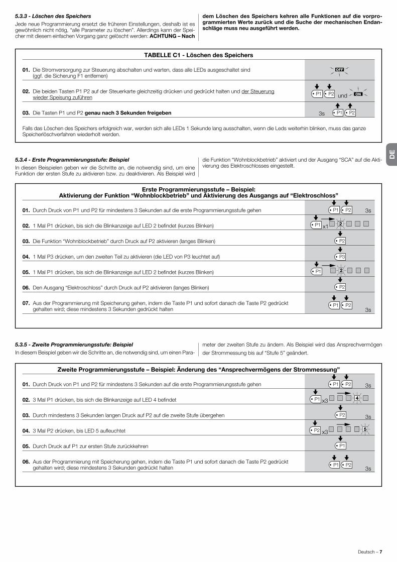
DE
Deutsch – 7
5.3.3 - Löschen des SpeichersJedeneueProgrammierungersetztdiefrüherenEinstellungen,deshalbistesgewöhnlich nicht nötig, “alle Parameter zu löschen”. Allerdings kann der Spei-chermitdiesemeinfachenVorgangganzgelöschtwerden:ACHTUNG – Nach
dem Löschen des Speichers kehren alle Funktionen auf die vorpro-grammierten Werte zurück und die Suche der mechanischen Endan-schläge muss neu ausgeführt werden.
5.3.4 - Erste Programmierungsstufe: BeispielIn diesen Beispielen geben wir die Schritte an, die notwendig sind, um eine Funktion der ersten Stufe zu aktivieren bzw. zu deaktivieren. Als Beispiel wird
dieFunktion“Wohnblockbetrieb”aktiviertundderAusgang“SCA”aufdieAkti-vierung des Elektroschlosses eingestellt.
Erste Programmierungsstufe – Beispiel:Aktivierung der Funktion “Wohnblockbetrieb” und Aktivierung des Ausgangs auf “Elektroschloss”
01. DurchDruckvonP1undP2fürmindestens3SekundenaufdieersteProgrammierungsstufegehen
02. 1MalP1drücken,bissichdieBlinkanzeigeaufLED2befindet(kurzesBlinken)
03. DieFunktion“Wohnblockbetrieb”durchDruckaufP2aktivieren(langesBlinken)
04. 1MalP3drücken,umdenzweitenTeilzuaktivieren(dieLEDvonP3leuchtetauf)
05. 1MalP1drücken,bissichdieBlinkanzeigeaufLED2befindet(kurzesBlinken)
06. DenAusgang“Elektroschloss”durchDruckaufP2aktivieren(langesBlinken)
07. AusderProgrammierungmitSpeicherunggehen,indemdieTasteP1undsofortdanachdieTasteP2gedrückt gehaltenwird;diesemindestens3Sekundengedrückthalten
Zweite Programmierungsstufe – Beispiel: Änderung des “Ansprechvermögens der Strommessung”
01. DurchDruckvonP1undP2fürmindestens3SekundenaufdieersteProgrammierungsstufegehen
02. 3MalP1drücken,bissichdieBlinkanzeigeaufLED4befindet
03. Durchmindestens3SekundenlangenDruckaufP2aufdiezweiteStufeübergehen
04. 3MalP2drücken,bisLED5aufleuchtet
05. DurchDruckaufP1zurerstenStufezurückkehren
06. AusderProgrammierungmitSpeicherunggehen,indemdieTasteP1undsofortdanachdieTasteP2gedrückt gehaltenwird;diesemindestens3Sekundengedrückthalten
5.3.5 - Zweite Programmierungsstufe: BeispielIn diesem Beispiel geben wir die Schritte an, die notwendig sind, um einen Para-
meter der zweiten Stufe zu ändern. Als Beispiel wird das Ansprechvermögen
derStrommessungbisauf“Stufe5”geändert.
P1 P2
2P1
P2
P3
P2
P1 P2
2P1
3s
3s
x1
P1 P2
3s
3s
3s
4P1
5P2
P2
P1
P1 P2
x3
x3
TABELLE C1 - Löschen des Speichers
01. Die Stromversorgung zur Steuerung abschalten und warten, dass alle LEDs ausgeschaltet sind (ggf.dieSicherungF1entfernen)
02. DiebeidenTastenP1P2aufderSteuerkartegleichzeitigdrückenundgedrückthaltenundder Steuerung wiederSpeisungzuführen
03. DieTastenP1undP2 genau nach 3 Sekunden freigeben
FallsdasLöschendesSpeicherserfolgreichwar,werdensichalleLEDs1Sekundelangausschalten,wenndieLedsweiterhinblinken,mussdasganzeSpeicherlöschverfahren wiederholt werden.
3s
P1 P2
P1 P2
und

DE
DE
8 – Deutsch
5.3.6 - Programmierungsschema
Auf der folgenden Abbildung ist das komplette Programmierungsschema der Funktionen und der jeweiligen Parameter gezeigt. Auf dieser Abbildung sind
auchdieursprünglicheingegebenenFunktionenundParameterbzw.dieFunktionen und Parameter angegeben, die nach einem vollständigen Löschen des Speichers eingestellt sind.
STOP Foto Foto1
Schr
ittbe
trieb
AUX
Normalbetrieb Led P1 Langsamblinken
Erste StufeLed P1 leuchtet fest
Zweite StufeLed P1 Schnellblinken o.p.
Typ 1o.p.
Typ 2
Nur
Öffn
ung
Nur
Sch
ließu
ng
Foto 2
alle Leuchtanzeigen aus · max. Stromaufnahme
P1+P23 Sek.lang
P13 Sek.lang
(nicht speichert)
P1+P23 Sek.lang(speichert)
Auto
mat
ische
Schl
ießu
ng
Woh
nblo
ckbe
trieb
Vorw
arne
n
Zula
uf n
ach
Foto
Verz
öger
ung
in Ö
ffnun
g OnOff
OnOff
HILFSEINGANG (*)
ENTLADEN
0 0,3 0,7
Sekunden
1,3 2
ANSPRECHVERMÖGEN STROMMESSUNG
1 2 3
Stufe
4 5
VERZÖGERUNG IN ÖFFNUNG
5 10 20
%
30 40
5 10 20
Sekunden
40 �0
PAUSEZEIT
P1P2
3 Sek.lang
P1
P1
P2
P3
P1
P2
P3
P1
P2
P3
P1
P2
P3
P1
P2
P3
P1
P2
P3
P2
P3
�ode
schl
oss
Stan
d by
� a
lles
Phot
otes
t
Stop
dur
ch re
sisti�
enW
iders
tand
Schw
ere
Tore
S�A
prop
ortio
nal
P3
P1
P2
P3
(*)T.Ö. Typ 1 TeilöffnungTyp1, BewegungdesoberenFlügels [NO-Kontakt]
T.Ö. Typ 2 TeilöffnungTyp2, Bewegung beider Antriebefür die Hälfte der Arbeitszeit [NO-Kontakt]
Nur Öffnung öffnet ➔ Stopp ➔ öffnet ➔ Stopp... [NO-Kontakt]
Nur Schließung schließt ➔ Stopp ➔ schließt ➔ Stopp... [NO-Kontakt.]
Photo 2 als Photo 2 benutzt [NC-Kontakt]

DE
Deutsch – 9
WEITERE AUSKÜNFTE Zubehör66.1 - Anschluss eines FunkempfängersAnderSteuerungbefindetsicheinVerbinderfürdasEinsteckeneiner4-kanali-genSM-Funkkarte,mitderdieSteuerungüberSender,dienachderfolgendenTabelleaufdieEingängeeinwirken,ferngesteuertwerdenkann.
Empfängerausgang Eingang der SteuerungNr.1 Schrittbetrieb
Nr.2 AUX(wiedereingestellterWert:TeilöffnungTyp1)
Nr.3 “NurÖffnung”
Nr. 4 “Nur Schließung”
6.2 - Anschluss der Pufferbatterie Mod. PS124DieSteuerungkannbeiStromausfallübereinePufferbatteriePS124gespeistwerden.ZurAusführungderInstallationundAnschlussderBatterie,wie inAbb. 10 gezeigt vorgehen.
6.3 - Anschluss des Systems SolemyoDieSteuerung istvorgerüstet,ummitdemPhotovoltaik-Speisungssystem“Solemyo”gespeistzuwerden(Photovoltaikkollektorund24V-Batterie).UmdenSpeicher“Solemyo”andieSteuerunganzuschließen,fürdiesedienormaler-weisefürdiePufferbatteriebestimmteSteckdoseverwenden(sieheAbb.6.2).
WICHTIG!- Wenn die Automatisierung durch das System “Solemyo” gespeist wird, darf sie NICHT GLEICHZEITIG auch durch das Stromnetz gespeist wer-den.- Das System “Solemyo” kann nur verwendet werden, wenn in der Steuerung die Funktion “Stand by - alles” Aktiv ist (ON) und wenn die Anschlüsse das Schema der Abb. 5a einhalten.
Keine LED ein:• PrüfenSie,obdieSteuerunggespeistist.AndenKlemmen9-10eineSpan-nungvonzirka30Vdcmessen(oder24VdcbeiBatteriespeisung).
•DiebeidenSicherungenüberprüfen;solltenichteinmaldieLEDP1einge-schaltet sein oder blinken, könnte es sich um einen schwereren Schaden handeln, deshalb muss die Steuerung ausgetauscht werden.
Die LED P1 blinkt regelmäßig, aber die LEDs EINGÄNGE L1, L2.. L5 spiegeln den Status der entsprechenden Eingänge nicht wider.• DieStromversorgungvorübergehendausschalten,umauseinermöglichen
Programmierphase auszusteigen.• DieVerbindungenandenKlemmen11..16genauüberprüfen.
Die Led P1 blinkt alle 4 Sekunden.• DieSteuerungistimZustand“Standby -alles”.
Das “automatische Suchverfahren” erfolgt nicht• Das “automatische Suchverfahren” erfolgt nur, wenn es vorher nie ausge-führtwurdeoderwennderSpeichergelöschtwurde.Umfestzustellen,obderSpeicherleerist,dieStromversorgungvorübergehendausschalten;beimEinschaltenmüssenalleLEDsca.6Sekundenlangschnellblinken.Wennsienur3Sekundenlangblinken,enthältderSpeicherbereitsgültigeWerte.Füreine neue “automatische Suche” muss der Speicher ganz gelöscht werden.
Das “automatische Suchverfahren” ist noch nie ausgeführt worden, trotzdem erfolgt das Verfahren nicht oder falsch• Um das “automatische Suchverfahren” zu aktivieren, muss die ganze Anlage
mit allen Sicherheitsvorrichtungen funktionieren.• Sicherstellen,dasskeinedermitdenEingängenverbundeneVorrichtungen
während der “automatischen Suche” ausgelöst wird.• Damitdie“automatischeSuche”korrektbeginnt,müssendieLEDsandenEingängenwieinAbb.11angegebeneingeschaltetsein.LEDP1mussein-mal pro Sekunde blinken.
Die “automatische Suche” wurde korrekt durchgeführt, aber es erfolgt keine Bewegung.• Prüfen,dassdieLEDsderSicherheitsvorrichtungen(STOPP,PHOTO,PHOTO1undeventuellPHOTO2)eingeschaltetsindunddieLEDdesaktiviertenSteuer-befehls(SCHRITTBETRIEBoderAUX)währenddesBefehlsaufleuchtet.
• Falls die Funktion “Phototest” aktiviert ist und die Photozellen nicht korrekt funktionieren,meldetdieDIAGNOSE-LEDdieStörungdurchein4-maligesBlinken.
Während der Bewegung führt das Tor eine Umkehrung aus.DieUrsachenfüreineUmkehrungsind:• EinAnsprechenderPhotozellen(PHOTO2währendderÖffnung,PHOTOoderPHOTO1währendderSchließung);indiesemFalldieVerbindungenderPhotozellenundggf.dieAnzeige-LEDsderEingängeüberprüfen.
WAS TUN, WENN…(Leitfaden zum Lösen von Problemen)7
• Ein Ansprechen der Strommessung während des Betriebs der Antriebe (also entferntvondenmechanischenEndanschlägen)wirdalsHindernisgedeu-tetundverursachteineUmkehrung.Umzuprüfen,obdieStrommessungeingegriffenhat,zählen,wieoftdieDIAGNOSE-LEDblinkt:1Blinkenzeigtan,dassdasAnsprechenderStrommessunganAntrieb1erfolgte,2MalBlinken an Antrieb 2.
WARTUNG DES PRODUKTS8Die Steuerung MC424, ein elektronisches Element, bedarf keiner besonderen Wartung.Dennochregelmäßigmindestensalle6MonatedieeinwandfreieEffi-zienz der ganzen Anlage nach den Angaben in Kapitel 3 kontrollieren.
ENTSORGUNG DES PRODUKTS
Das vorliegende Produkt ist Bestandteil der Automation und muss daher zusammen mit ihr entsorgt werden.WiedieInstallationsarbeitenmussauchdieAbrüstungamEndederLebens-dauerdiesesProduktsdurchFachpersonalausgeführtwerden.
Dieses Produkt besteht aus verschiedenen Stoffen, von denen einige recycelt werdenkönnen,anderemüssenhingegenentsorgtwerden.InformierenSiesichüberdieRecycling-oderEntsorgungssystemefürdiesesProdukt,dievondeninIhremGebietgültigenVerordnungenvorgesehensind.
Achtung! –BestimmteTeiledesProduktskönnenSchadstoffeodergefährli-cheSubstanzenenthalten,die,fallsindieUmweltgeworfen,schädlicheWir-kungen auf die Umwelt und die Gesundheit der Menschen haben könnten.
WiedurchdasSymbolseitlichangegeben,istesverboten,diesesProduktzumHaushaltsmüllzugeben.Dahergetrenntgemäß den Methoden entsorgen, die von den in Ihrem GebietgültigenVerordnungenvorgesehensind,oderdasProduktdemVerkäuferbeimKaufeinesneuen,gleichwer-tigenProduktszurückgeben.
Achtung! –dieörtlichenVerordnungenkönnenschwereStrafenimFalleinerwiderrechtlichen Entsorgung dieses Produkts vorsehen.

DE
10 – Deutsch
HINWEISE:•AlleangegebenentechnischenMerkmalebeziehensichaufeineTemperaturvon20°C(±5°C).•NiceS.p.a.behältsichdasRechtvor,jederzeitfürnotwendig betrachtete Änderungen am Produkt vorzunehmen, wobei Funktionalitäten und Einsatzzweck beibehalten werden.
Netzstromversorgung SteuerungMC424:230V~±10%50-60Hz SteuerungMC424/V1:120V~±10%50-60Hz
Max. Leistungsaufnahme 170W
Notversorgung vorgerüstetfürPufferbatterienPS124undfürSolar-KitSolemyo
Max. Stromaufnahme der Antriebe 3A(AnsprechenderStrommessung“Stufe6”)
Ausgang für die Versorgung von Nebeneinrichtungen 24V 24VdcHöchststrom200mA(Spannungvon16bis33V dc)
Ausgang Phototest 24V dcHöchststrom100mA(Spannungvon16bis33V dc)
Ausgang Blinkleuchte für24V dcBlinkleuchten,Höchstleistung25W(Spannungvon16bis33V dc)
Ausgang Kontrolllampe Tor für24V 24VdcLampen,Höchstleistung5W(Spannungvon16bis33V dc) oderElektroschloss12V~25W
Eingang Stopp fürNC-Kontakteoderkonstanten8,2KΩWiderstand+/-25%
Arbeitszeit automatisch gemessen
Pausezeit programmierbarauf5,10,20,40,80Sekunden
Entladungszeit programmierbarauf0,0,3,0,7,1,3,2Sekunden
Verzögerung Torflügel während der Öffnung programmierbarauf5,10,20,30,40%derArbeitszeit
Verzögerung Torflügel während der Schließung automatisch gemessen
Ausgang 1. Antrieb fürAntriebeWingoWG4024-WG5024
Ausgang 2. Antrieb fürAntriebeWingoWG4024-WG5024Max. Kabellänge Stromversorgung 30m SpeisungüberSolar-KitSolemyo 3m Antriebe 10m andereEingänge/Ausgänge 30m Blinkleuchte 10m SCA 30m Elektroschloss 10m Antenne 20m (unter 3 m empfohlen)
Funkempfänger KupplungTyp“SM”fürEmpfängerSMXI,SMXIS,OXI(ModusIundModusII)
Betriebstemperatur von-20bis50°C
Schutzart IP54(unbeschädigtesGehäuse)
Abmessungen (mm) 310x232xH122
Gewicht (kg) 4,1
TECHNISCHE MERKMALE DES PRODUKTS
EG-KonformitätserklärungErklärung gemäß den Richtlinien: 2004/108/EG (EMC); 2006/42/EG (MD) Anhang II, Teil B
Hinweis - Der Inhalt dieser Konformitätserklärung entspricht den Angaben im offiziellen Dokument, das am Firmensitz der Nice S.p.a. aufbewahrt wird, in dessen Fassung zum Zeitpunkt der Drucklegung dieser Anleitung . Dieser Text wurde aus redaktionellen Gründen angepasst . Eine Kopie der Originalerklärung kann bei Nice S .p .a . (TV) I angefordert werden .
Nummer:296/MC424 Revision: 3 Sprache: DE
Hersteller: Nice s.p.a.Adresse: ViaPezzaAlta13,Z.I.Rustignè,31046Oderzo(TV)ItalyFür die Zusammenstellung der technischen Dokumentation autorisierte Person: Nice s.p.a.Produkttyp: Steuerungmit2Antrieben24Vdc.Modell / Typ: MC424Zubehör: Funkempfänger SMXI, SMXIS
DerUnterzeichnerMauroSordinierklärthiermiteigenverantwortlichalsChiefExecutiveOfficer,dassdasobengenannteGerätdieVorschriftenderfolgendenRichtlinienerfüllt:•RICHTLINIE2004/108/EGDESEUROPÄISCHENPARLAMENTSUNDDESRATSvom15.Dezember2004zurAngleichungderRechtsvorschriftenderMitgliedstaatenüberdieelektromagnetischeVerträglichkeitundAufhebungderRichtlinie89/336/EWGgemäßfolgendenharmonisierendenNormen:EN61000-6-2:2005,EN61000-6-3:2007+A1:2011
Außerdem entspricht das Gerät im Sinne der Anforderungen an „unvollständige Maschinen“ folgender Richtlinie: Richtlinie2006/42/EGDESEUROPÄISCHENPARLAMENTSUNDDESRATSvom17.Mai2006überMaschinenzurÄnderungderRichtlinie95/16/EG(Überarbeitung)•DerHerstellererklärthiermit,dassdieeinschlägigetechnischeDokumentationinKonformitätzuAnhangVIIBderRichtlinie2006/42/EGverfasstwurdeundfolgendegrundlegen-deAnforderungenerfülltsind:1.1-1.1.2-1.1.3-1.2.1-1.2.6-1.5.1-1.5.2-1.5.5-1.5.6-1.5.7-1.5.8-1.5.10-1.5.11•DerHerstellerverpflichtetsich,denzuständigenStellendereinzelnenLänderbeibegründeterAnfrageunterWahrungseinerRechteamgeistigenEigentumdieentsprechendenInformationenüberdieunvollständigeMaschinezuübermitteln.•FallsdieunvollständigeMaschineineinemeuropäischenLandinBetriebgenommenwird,dessenoffizielleLandessprachenichtmitderSprachedieserErklärungübereinstimmt,istderImporteurverpflichtet,dieserErklärungdieentsprechendeÜbersetzungbeizulegen.• Es wird darauf hingewiesen, dass die unvollständige Maschine nicht in Betrieb genommen werden darf, bevor ebenfalls die Konformität der Maschine, in die sie eingebaut werden soll,zuRichtlinie2006/42/EGerklärtwurde.
Ferner entspricht das Produkt folgenden Normen:EN60335-1:2002+A1:2004+A11:2004+A12:2006+A2:2006+A13:2008+A14:2010+A15:2011,EN60335-2-103:2003+A11:2009
DasProdukterfüllt,aufdieanwendbarenTeilebegrenzt,folgendeNormen:EN13241-1:2003+A1:2011,EN12445:2002,EN12453:2002,EN12978:2003+A1:2009
Oderzo,30Juli2014 Ing.MauroSordini(ChiefExecutiveOfficer)

DE
Deutsch – 11
SMXI,SMXISsind4-Kanal-FunkempfängerfürSteuerungen,diemitSteckver-binder SM ausgestattet sind. Die kompatiblen Sender haben die Besonderheit, dassderErkennungscodefürjedenSenderandersist.DamitderEmpfängereinen bestimmten Sender erkennt, muss der Erkennungscode gespeichert werden.DieserVorgangwirdfürjedenSender,derzurSteuerungderSteuer-zentrale benutzt werden soll, einzeln wiederholt.
Anmerkungen:– Im Empfänger können bis max . 256 Sender gespeichert werden . Ein einzelner Sender kann nicht gelöscht werden, die Codenummern können nur alle gleich-zeitig gelöscht werden .- Für fortgeschrittenere Funktionen verwenden Sie bitte das spezielle Program-mierungsgerät .
BESCHREIBUNG DES PRODUKTS1DerEmpfängerhat4Ausgänge,diealleamVerbinderuntenzurVerfügungstehen;umzuwissen,welcheFunktionjederAusganghat,wirdaufdieAnwei-sungenlautKapitel6.1verwiesen.In der Speicherphase der Codenummer des Senders stehen 2 Möglichkeiten zur Auswahl:Modus I - Tabelle B1:JedeTastedesSendersaktiviertdenentsprechendenAusgangdesEmpfängers,d.h.dieTaste1aktiviertAusgang1,Taste2akti-viertAusgang2,usw.IndiesemFallgibtesnureineSpeicherphasefürjedenSender.WährenddieserPhaseistesunwichtig,welcheTastegedrücktwird,es wird nur eine einzige Speicherstelle besetzt.Modus II - Tabelle B1:JederTastedesSenderskanneinbestimmterAus-gangdesEmpfängerszugeordnetwerden,z.B.Taste1aktiviertAusgang2,Taste2aktiviertAusgang1usw.IndiesemFallmussderSendergespeichertwerden, indemmandiegewünschteTastefür jedenAusgang,deraktiviertwerdensoll,drückt.NatürlichkannjedeTastenureineneinzigenAusgangakti-vieren,währendderselbeAusgangdurchDrückenmehrererTastenaktiviertwerdenkann.FürjedeTastewirdnureineSpeicherstellebelegt.
TABELLE B1 - Speichern I (Alle Tasten werden am jeweiligen Ausgang des Empfängers gespeichert)
01. DrückenSiedenDruckknopfmindestens3Sekundenlang
02. WenndieLeuchtanzeigeaufleuchtet,lassenSiedenDruckknopflos
03. Innerhalbvon10Sekundenmindestens2SekundenlangaufeinebeliebigeTastedeszuspeicherndenSendersdrücken
Anmerkung – Wenn richtig gespeichert wurde, leuchtet die Leuchtanzeige des Empfängers dreimal auf . Wenn Sie weitere Sender speichern möchten, wiederholen Sie den Vorgang 3 innerhalb von weiteren 10 Sekunden
INSTALLIEREN EINER ANTENNE2FüreineneinwandfreienBetriebmussderEmpfängermiteinerABF-oderABF-KIT-Antenneausgestattetwerden;ohneAntenneistdieLeistungaufwenigeMeterbegrenzt.DieAntennemusssohochwiemöglichangebrachtwerden;wenn Strukturen aus Metall oder Stahlbeton vorhanden sind, installieren Sie die AntenneüberdiesenStrukturen.WenndaszurAntennegehörigeKabelzukurzist,benutzenSieeinKoaxialkabelmit50OhmImpedanz(z.B.RG58mitniedri-gemVerlust),dasKabeldarfnichtlängerals10msein.WenndieAntennenichtaufeinerebenenUnterlage (Wand)montiertwird,kanndieKlemmedesGeflechtsgeerdetwerden,umeinegrößereLeistungzugewährleisten.NatürlichmussdieErdungsachgemäßinderNäheausgeführtwerden.SolltedieMontageeinerABF-oderABFKIT-Antenneunmöglichsein,können gute Ergebnisse mit der dem Empfänger beiliegenden Leitung als Antenne erzielt werden.
ACHTUNG – In der Speicherphase wird jeder richtig erkannte Sen-der im Empfangsbereich des Funks gespeichert. Beachten Sie dies aufmerksam und stecken Sie eventuell die Antenne aus, um die Leistung des Empfängers zu reduzieren.
Die Speichervorgänge zum Speichern der Fernbedienungen sind zeitlich begrenzt: deshalb ist es wichtig, sich den ganzen Speichervorgang vor dem Speichern durchzulesen und zu verstehen. ZurDurchführungdesfolgendenVerfahrensmüssendieTasteamGehäusedes Funkempfängers (siehe A, Abb. 1b)unddiejeweiligeLed(sieheB, Abb. 1b)linksnebenderTastebenutztwerden.
1a
TABELLE B2 - Speichern Art II (Jeder Taste kann ein besonderer Ausgang des Empfängers zugeordnet werden)
01. DrückenSiedenDruckknopfaufdemEmpfängerundlassenSieihnsooftlos,wiedieZahldesgewünschten Ausgangsist(1MalfürAusgangNr.1,2MalfürAusgangNr.2)
02. Prüfen,obdieLEDsooftblinkt,wiedergewünschteAusganglautet(regelmäßigin10Sekundenwiederholt) (1MalBlinkenfürAusgangNr.1,2MalBlinkenfürAusgangNr.2)
03. DrückenSiediegewünschteTastedeszuspeicherndenSendersinnerhalbvon10Sekundenmindestens2Sekundenlang
Anmerkung – Wenn richtig gespeichert wurde, leuchtet die Leuchtanzeige des Empfängers dreimal auf . Wenn Sie weitere Sender speichern möchten, wiederholen Sie Vorgang 3 innerhalb von weiteren 10 Sekunden
smxi - smxis Funkempfänger0682
3sRX
TX
RX
2s
x3
2s
x3
RX
TX
SPEICHERN EINER FERNBEDIENUNG3

DE
12 – Deutsch
FernspeicherungEinneuerSenderkannimSpeicherdesEmpfängersauchohneDrückendesTastenfeldesgespeichertwerden,wennmaneinebereitsgespeicherteundfunktionierende Fernbedienung besitzt. Der neue Sender erhält die Eigenschaf-ten des bereits gespeicherten Senders. Deshalb wird der neue Sender auf Modus I gespeichert, wenn der alte Sender auf Modus I gespeichert ist. Dazu kanneinebeliebigeSendertastegedrücktwerden.WennderersteSenderaufModusIIgespeichertwurde,wirdauchderneueaufModusIIgespeichert;
allerdingsmussaufdemerstenSenderdieTastegedrücktwerden,diedengewünschtenAusgangaktiviertundaufdemzweitenSenderdieTaste,diegespeichertwerdensoll.VorderDurchführungdereinzelnenVorgängemüs-sen alle Anweisungen gelesen werden. Sich nun mit den beiden Fernbedie-nungen (die, in die der Code eingegeben werden muss, werden wir mit NEU bezeichnen,die,mitdembereitsgespeichertenCode,mitALT)indenAkti-onskreisderFunksteuerungen(innerhalbdermaximalenReichweite)begebenunddieinderTabelleverzeichnetenSchrittedurchführen.
TABELLE B4 - Löschen aller Sender
01. DrückenSiedenEmpfängernundhaltenSieihngedrückt
02. WartenSiebisdieLeuchtanzeigeangehtundanschließendwiederausgeht,solange,bisdiesedreimalaufgeleuchtethat
03. LassenSiedieTastegenauwährenddem3.Blinkenlos
Anmerkung – Wenn der Vorgang richtig ausgeführt wurde, leuchtet die Leuchtanzeige kurz danach fünfmal auf
Dank folgendem Ablauf können alle Codenummern des Speichers gelöscht werden.
LÖSCHEN ALLER SENDER4
TECHNISCHE MERKMALE DES PRODUKTS
Empfänger: SMXI SMXISDecodierung Rolling code 52bitFLOR Rollingcode 64bitSMILOKompatibilität der Sender FLOR,VERYVR,NICEWAY,ERGO,PLANO,NICEONE SMILO
Frequenz 433.92 MHz 433.92 MHz
Eingangsimpedanz 52KΩ 52KΩAusgänge 4(aufVerbinderSM) 4(aufVerbinderSM)
Empfindlichkeit besser als 0.5µV besser als 0.5µV
Betriebstemperatur -10°Cbis+55°C -10°Cbis+55°C
SENDER: FLO2R SMILOTasten 1,2oder4jenachVersion 2oder4
Stromversorgung 12V Batt.23A 12V Batt. 23 A
Aufnahme 10mA 25mA
Übertragungsfrequenz 433.92 MHz 433.92 MHz
Betriebstemp. -10°Cbis+55°C -10°Cbis+55°C
Abgestrahlte Leistung Geschätzt:ca.1mWe.r.p. Geschätzt:ca.1mWe.r.p.
Reichweite Geschätzt:200m(außen);35m(inGebäuden) Geschätzt:200m(außen);35m(inGebäuden)
Abmessungen / Gewicht 69x39x15,5mm/31g. Ø48mmxH14mm-14g
Codierung digital(4,5MillionenMilliardenanKombinationen) Digital(18MilliardenMilliardenanKombinationen)
HINWEISE:•AlleangegebenentechnischenMerkmalebeziehensichaufeineTemperaturvon20°C(±5°C).•NiceS.p.a.behältsichdasRechtvor,jederzeitfürnotwendigbetrachteteÄnderungenamProduktvorzunehmen,wobeiFunktionalitätenundEinsatzzweckbeibehaltenwerden.•DieReichweitederSenderund die Empfangskapazität der Empfänger kann Störungen unterworfen sein, die die Leistungen beeinträchtigen. Im Fall von Interferenzen kann Nice daher die effektiveReichweiteihrerVorrichtungennichtgarantieren.
TABELLE B3 - Fernspeicherung
01. Mindestens5Sek.aufdieTastedesNEUENSendersdrücken,dannloslassen
02. MallangsamaufdieTastedesALTENSendersdrücken
03. 1MallangsamaufdieTastedesNEUENSendersdrücken,dannloslassen
Anmerkung – Zur Speicherung weiterer Sender, alle Schritte für jeden neuen Sender wiederholen
1s
x1
TX
TX TX TX
TX
TX
1s1s
x5s
RX
RX
x3
3°
x5

PL
Polski – 1
POLSKI
Zalecenia dotyczące bezpieczeństwa• UWAGA! – Niniejsza instrukcja zawiera uwagi i zalecenia ważne dla
be z pieczeństwa osób obsługujących urządzenie.Nieprawidłowowyko-nanainstalacjamożebyćprzyczynąpoważnychobrażeń.Dlategoteżprzedrozpoczęciempracynależydokładnieprzeczytaćkażdączęśćinstrukcji.Prze-rwaćinstalowanieurządzeniawprzypadkuwątpliwościjakiegokolwiekcharak-teruizwrócićsięoewentualnewyjaśnieniadoSerwisuTechnicznegoNice.
• UWAGA! – starannie przechowywać tę instrukcję w celu ułatwienia ewentualnych operacji konserwacji i utylizacji urządzenia.
Zalecenia dotyczące instalacji•Przedrozpoczęcieminstalacjisprawdź,czyurządzeniejestodpowiedniedlaokreślonegozastosowania(patrzparagraf2.2“Ograniczeniazastosowania”orazrozdział“Parametrytechniczneurządzenia”).
JeżeliniejestonoodpowiednieNIEprzystępujdojegoinstalacji.•Podczasmontażuostrożnieobchodźsięzurządzeniem,unikajzgnieceń,uderzeń,upadkówlubzetknięciazjakimikolwiekpłynami.Nieumieszczajurządzeniawpobliżuźródełciepłainienarażajgonadziałanieotwartegoognia.Opisanewyżejsytuacjemogąbyćprzyczynąuszkodzeniaurządzenia,jegonieprawidłowegofunkcjonowanialubteżmogąpowodowaćzagroże-nia.JeżelijednakdoszłobydoktórejśzopisanychwyżejsytuacjinatychmiastprzerwijmontażizwróćsięopomocdoSerwisuTechnicznegoNice.
•Niewprowadzajmodyfikacjidożadnejczęściurządzenia.Operacjeniedo-zwolonemogąwyłączniepowodowaćjegonieprawidłowefunkcjonowanie.Producentzrzekasięwszelkiejodpowiedzialnościzaszkody,wynikającezsamowolniewykonywanychmodyfikacjiurządzenia.
•Urządzenieniejestprzeznaczonedoużytkuprzezosoby,(włączniezdzieć-mi)ozredukowanychzdolnościachfizycznych,czuciowychiumysłowychlubnieposiadającedoświadczeniawobsłudzelubznajomościurządzenia,chybażemogłyoneskorzystać,poprzezpośrednictwoosobyodpowiedzialnejzaichbezpieczeństwo,znadzorulubinstrukcjidotyczącychobsługi.
•Niepozwalajdzieciombawićsięurządzeniamisterującymiautomatyką.Prze-chowujnadajnikizdalaodzasięgudzieci.
•Dziecimusząznajdowaćsiępodnadzoremosóbdorosłych,którychobo-wiązkiemjestupewnićsię,żeniebawiąsięoneurządzeniem.
•Naliniizasilającejautomatykę,prowadzącejzsiecielektrycznejnależyprze-widziećwbudowanieurządzeniarozłączającegozasilanieigwarantującegoodległośćpomiędzystykami,umożliwiającącałkowiterozłączeniewwarun-kachIIIkategoriiprzepięcia.
•Podłączcentralędoliniizasilaniaelektrycznegowyposażonąwuziemienie.•Opakowanieurządzeniamusibyćzlikwidowanezgodniezodpowiednimiprzepisamiobowiązującyminadanymterytorium.
INSTRUKCJE I ZALECENIA DOTYCZĄCEBEZPIECZEŃSTWA
CentralaMC424przeznaczonajestdosterowaniasiłownikówelektromecha-nicznychWingona24V,wykorzystywanychdoautomatyzacjibramlubdrzwiskrzydłowych.UWAGA! – Każde inne jej zastosowanie, odmienne od opi-sanego oraz zastosowanie w warunkach środowiskowych odmiennych od podanych w tej instrukcji jest niewłaściwe i zabronione!CentralaMC424wyposażonajestwsystemweryfikującyobciążeniesilnikówdoniejpodłączonych(amperometryka);tensystemsłużydoautomatycznegoodczytywaniapozycjikrańcowych,zapisywaniaczasupracykażdegosilnikaorazdowykrywaniaewentualnychprzeszkód,któremogąwystąpićpodczasnormalnegoruchu.Tacechaułatwiajegoinstalowanie,ponieważniewymagaregulacjiczasupracyiprzesunięciafazowegoskrzydełbramy.Centralazostałazaprogramowanafabrycznienafunkcjenajczęściejużywane;możliwyjestwybórdodatkowych,specyficznychfunkcjizzastosowaniempro-stejproceduryprogramowania(patrzrozdział5).Centrala jest przystosowana do zasilania pobieranego z akumulatora awaryjnego PS124,realizującegozasilanieawaryjnewprzypadkuprzerwywdopływienapięciasieciowego,(abyuzyskaćwięcejinformacjinależyprzeczytaćrozdział6.2).Jestonarównieżprzystosowanadopodłączeniadosystemuzasilaniaenergiąsłonecz-ną-“Solemyo”,(abyuzyskaćwięcejinformacjinależyprzeczytaćrozdział6.3).
OPIS URZĄDZENIA1
Mającnaceluwyjaśnienieniektórychpojęćiaspektówdotyczącychdrzwilubbramdwuskrzydłowychprzedstawiamyponiżejtypowąinstalacjęrys. 1.Legenda rys. 1:1. SiłownikelektromechanicznyWingona24V2. SilownikelektromechanicznyWingona24V3. Lampa ostrzegawcza Lucy244. Przełącznikkluczowy5. Dwiefotokomórki“FOTO”6. Dwiefotokomórki“FOTO1”7. Dwiefotokomórki“FOTO2”8. Centralasterująca
INSTALACJA2
Spistreści INSTRUKCJE I ZALECENIA DOTYCZĄCE BEZPIECZEŃSTWA . . 1
1 – OPIS URZĄDZENIA . . . . . . . . . . . . . . . . . . . . . . . . . . . . . . . . . . . . . . 1
2 – INSTALACJA . . . . . . . . . . . . . . . . . . . . . . . . . . . . . . . . . . . . . . . . . . . 1
2.1 - KONTROLA WSTĘPNA DO WYKONANIA PODCZAS INSTALACJA . . . . . . . . . . . . . . . . . . . . . . . . . . . . . . . . . . . . . . . . . . . 2
2.2 - OGRANICZENIA ZASTOSOWANIA URZĄDZENIA . . . . . . . . . 2
2.3 - INSTALACJA . . . . . . . . . . . . . . . . . . . . . . . . . . . . . . . . . . . . . . . 2
2.4 - PODŁĄCZENIA ELEKTRYCZNE . . . . . . . . . . . . . . . . . . . . . . . 2 2.4.1 - Uwagi dotyczące połączeń . . . . . . . . . . . . . . . . . . . . . . 3 2.4.2 - Rodzaje wejścia STOP . . . . . . . . . . . . . . . . . . . . . . . . . 3 2.4.3 - Przykłady połączenia fotokomórek: z aktywną funkcją “Stand by całego urządzenia” i nieaktywną funkcją fototest . . . . . . . . . . . . . . . . . . . . . . . . . . . . . . . 3 2.4.4 - Przykłady połączenia fotokomórek: z aktywną funkcją fototest i nieaktywną funkcją “Stand by całego urządzenia” . . . . . . . . . . . . . . . . . . . . . . . . . . . . . . . . . . 3
2.5 - PIERWSZE WŁĄCZENIE I KONTROLA POŁĄCZEŃ . . . . . . . . 3
2.6 - AUTOMATYCZNE WYSZUKIWANIE POŁOŻEŃ KRAŃCOWYCH 3
3 – PRÓBA ODBIORCZA I PRZEKAZANIE DO EKSPLOATACJI . . . . . 4
3.1 - PRÓBA ODBIORCZA . . . . . . . . . . . . . . . . . . . . . . . . . . . . . . . . 4
3.2 - PRZEKAZANIE DO EKSPLOATACJI . . . . . . . . . . . . . . . . . . . . 4
4 – DIAGNOSTYKA . . . . . . . . . . . . . . . . . . . . . . . . . . . . . . . . . . . . . . . . . 4
5 – PROGRAMOWANIE . . . . . . . . . . . . . . . . . . . . . . . . . . . . . . . . . . . . . . 4
5.1 - FUNKCJE USTAWIONE FABRYCZNIE . . . . . . . . . . . . . . . . . . 4
5.2 - FUNKCJE PROGRAMOWALNE . . . . . . . . . . . . . . . . . . . . . . . . 4 5.2.1 - Programowanie bezpośrednie . . . . . . . . . . . . . . . . . . . 5 5.2.2 - Funkcje na pierwszym poziomie programowania: pierwsza część . . . . . . . . . . . . . . . . . . . . . . . . . . . . . . . 5 5.2.3 - Funkcje na pierwszym poziomie programowania: druga część . . . . . . . . . . . . . . . . . . . . . . . . . . . . . . . . . . 5 5.2.4 - Funkcje na drugim poziomieprogramowania . . . . . . . 5
5.3 - TRYB PROGRAMOWANIA . . . . . . . . . . . . . . . . . . . . . . . . . . . . 5 5.3.1 - Programowanie na pierwszym poziomie: funkcje . . . 6 5.3.2 - Programowanie na drugim poziomie: parametry . . . . 6 5.3.3 - Kasowanie pamięci . . . . . . . . . . . . . . . . . . . . . . . . . . . . 7 5.3.4 - Przykład programowania na pierwszym poziomie . . . 7 5.3.5 - Przykład programowania na drugim poziomie . . . . . . 7 5.3.6 - Schemat programowania . . . . . . . . . . . . . . . . . . . . . . . 8
6 – SZCZEGÓŁOWE INFORMACJE o akcesoriach . . . . . . . . . . . . . . . 9
6.1 - PODŁĄCZENIE ODBIORNIKA RADIOWEGO . . . . . . . . . . . . . 9
6.2 - PODŁĄCZENIE AKUMULATORA AWARYJNEGO MOD. PS124 9
6.3 - PODŁĄCZENIE SYSTEMU SOLEMYO . . . . . . . . . . . . . . . . . . 9
7 – CO ZROBIĆ JEŚLI...(przewodnik do rozwiązywania problemów) . . . 9
8 – KONSERWACJA URZĄDZENIA . . . . . . . . . . . . . . . . . . . . . . . . . . . . 9
UTYLIZACJA URZĄDZENIA . . . . . . . . . . . . . . . . . . . . . . . . . . . . . . . 9
PARAMETRY TECHNICZNE URZĄDZENIA . . . . . . . . . . . . . . . . . 10
DEKLARACJA ZGODNOŚCI CE . . . . . . . . . . . . . . . . . . . . . . . . . . . 10
ODBIORNIK RADIOWY: SMXI - SMXIS . . . . . . . . . . . . . . . . . . . . . 11
1 - OPIS URZĄDZENIA . . . . . . . . . . . . . . . . . . . . . . . . . . . . . . . . . . 11 2 - INSTALOWANIE ANTENY . . . . . . . . . . . . . . . . . . . . . . . . . . . . . 11 3 - WCZYTYWANIE PILOTA . . . . . . . . . . . . . . . . . . . . . . . . . . . . . . 11 4 - KASOWANIE WSZYSTKICH KODÓW NADAJNIKÓW . . . . . . . 12
PARAMETRY TECHNICZNE URZĄDZENIA . . . . . . . . . . . . . . . . . 12
ZDJĘCIA . . . . . . . . . . . . . . . . . . . . . . . . . . . . . . . . . . . . . . . . . . . . . I-V
Instrukcje oryginalne
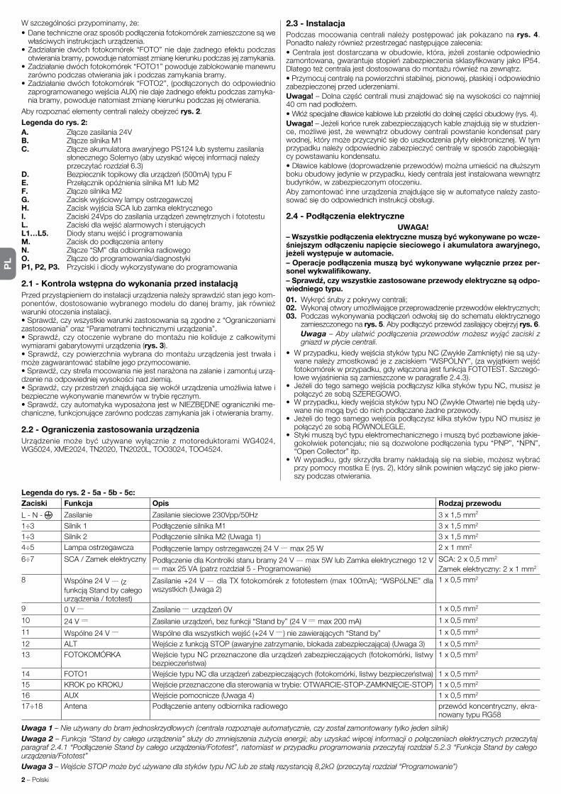
PL
2 – Polski
Wszczególnościprzypominamy,że:•Danetechniczneorazsposóbpodłączeniafotokomórekzamieszczonesąwewłaściwychinstrukcjachurządzenia.
•Zadziałaniedwóchfotokomórek“FOTO”niedajeżadnegoefektupodczasotwieraniabramy,powodujenatomiastzmianękierunkupodczasjejzamykania.
•Zadziałaniedwóchfotokomórek“FOTO1”powodujezablokowaniemanewruzarówno podczas otwierania jak i podczas zamykania bramy.
•Zadziałaniedwóchfotokomórek“FOTO2”,(podłączonychdoodpowiedniozaprogramowanegowejściaAUX)niedajeżadnegoefektupodczaszamyka-niabramy,powodujenatomiastzmianękierunkupodczasjejotwierania.
Abyrozpoznaćelementycentralinależyobejrzećrys. 2.Legenda do rys. 2:A. Złączezasilania24VB. ZłączesilnikaM1C. ZłączeakumulatoraawaryjnegoPS124lubsystemuzasilania słonecznegoSolemyo(abyuzyskaćwięcejinformacjinależy przeczytaćrozdział6.3)D. Bezpieczniktopikowydlaurządzeń(500mA)typuFE. PrzełącznikopóźnieniasilnikaM1lubM2F. ZłączesilnikaM2G. ZaciskwyjściowylampyostrzegawczejH. ZaciskwyjściaSCAlubzamkaelektrycznegoI. Zaciski24VpsdozasilaniaurządzeńzewnętrznychifototestuL. ZaciskidlawejśćalarmowychisterującychL1…L5. DiodystanuwejśćiprogramowaniaM. ZaciskdopodłączeniaantenyN. Złącze“SM”dlaodbiornikaradiowegoO. Złączedoprogramowania/diagnostykiP1, P2, P3. Przyciski i diody wykorzystywane do programowania
2.1 - Kontrola wstępna do wykonania przed instalacjąPrzedprzystąpieniemdoinstalacjiurządzenianależysprawdzićstanjegokom-ponentów,dostosowaniewybranegomodeludodanejbramy, jakrównieżwarunki otoczenia instalacji.•Sprawdź,czywszystkiewarunkizastosowaniasązgodnez“Ograniczeniamizastosowania”oraz“Parametramitechnicznymiurządzenia”.•Sprawdź,czyotoczeniewybranedomontażuniekolidujezcałkowitymiwymiaramigabarytowymiurządzenia(rys. 3).•Sprawdź,czypowierzchniawybranadomontażuurządzeniajesttrwałaimożezagwarantowaćstabilnejegoprzymocowanie.•Sprawdź,czystrefamocowanianiejestnarażonanazalanieizamontujurzą-dzenienaodpowiedniejwysokościnadziemią.•Sprawdź,czyprzestrzeńznajdującasięwokółurządzeniaumożliwiałatweibezpiecznewykonywaniemanewrówwtrybieręcznym.•Sprawdź,czyautomatykawyposażonajestwNIEZBĘDNEogranicznikime-chaniczne,funkcjonującezarównopodczaszamykaniajakiotwieraniabramy.
2.2 - Ograniczenia zastosowania urządzeniaUrządzeniemoże być używanewyłącznie zmotoreduktoramiWG4024,WG5024,XME2024,TN2020,TN2020L,TOO3024,TOO4524.
2.3 - InstalacjaPodczasmocowaniacentralinależypostępować jakpokazanonarys. 4. Ponadtonależyrównieżprzestrzegaćnastępującezalecenia:•Centralajestdostarczanawobudowie,która,jeżelizostanieodpowiedniozamontowana,gwarantujestopieńzabezpieczeniasklasyfikowanyjakoIP54.Dlategoteżcentralajestdostosowanadomontażurównieżnazewnątrz.•Przymocujcentralęnapowierzchnistabilnej,pionowej,płaskiejiodpowiedniozabezpieczonej przed uderzeniami. Uwaga! –Dolnaczęśćcentralimusiznajdowaćsięnawysokościconajmniej40cmnadpodłożem.•Włóżspecjalnedławicekablowelubprzelotkidodolnejczęściobudowy(rys.4).Uwaga! –Jeżelikońcerurekzabezpieczającychkableznajdująsięwstudzien-ce,możliwejest,żewewnątrzobudowycentralipowstaniekondensatparywodnej,którymożeprzyczynićsiędouszkodzeniapłytyelektronicznej.Wtymprzypadkunależyodpowiedniozabezpieczyćcentralęwsposóbzapobiegają-cy powstawaniu kondensatu.•Dławicekablowe(doprowadzenieprzewodów)możnaumieścićnadłuższymbokuobudowyjedyniewprzypadku,kiedycentralajestinstalowanawewnątrzbudynków, w zabezpieczonym otoczeniu.Abyzamontowaćinneurządzeniaznajdującesięwautomatycenależyzasto-sowaćsiędoodpowiednichinstrukcjiobsługi.
2.4 - Podłączenia elektryczneUWAGA!
– Wszystkie podłączenia elektryczne muszą być wykonywane po wcze-śniejszym odłączeniu napięcie sieciowego i akumulatora awaryjnego, jeżeli występuje w automacie.– Operacje podłączenia muszą być wykonywane wyłącznie przez per-sonel wykwalifikowany.– Sprawdź, czy wszystkie zastosowane przewody elektryczne są odpo-wiedniego typu.01. Wykręćśrubyzpokrywycentrali;02. Wykonajotworyumożliwiająceprzeprowadzenieprzewodówelektrycznych;03. Podczaswykonywaniapodłączeńodwołajsiędoschematuelektrycznego
za mieszczonego na rys. 5.Abypodłączyćprzewódzasilającyobejrzyjrys. 6. Uwaga – Aby ułatwić podłączenia przewodów możesz wyjąć zaciski z
gniazd w płycie centrali.• Wprzypadku,kiedywejściastykówtypuNC(ZwykleZamknięty)niesąuży-wanenależyzmostkowaćjezzaciskiem“WSPÓLNY”,(zawyjątkiemwejśćfotokomórekwprzypadku,gdywłączonajestfunkcjaFOTOTEST.Szczegó-łowewyjaśnieniasązamieszczonewparagrafie2.4.3).
• JeżelidotegosamegowejściapodłączyszkilkastykówtypuNC,musiszjepołączyćzesobąSZEREGOWO.
• Wprzypadku,kiedywejściastykówtypuNO(ZwykleOtwarte)niebędąuży-waneniemogąbyćdonichpodłączaneżadneprzewody.
• JeżelidotegosamegowejściapodłączyszkilkastykówtypuNOmusiszjepołączyćzesobąRÓWNOLEGLE.
• Stykimusząbyćtypuelektromechanicznegoimusząbyćpozbawionejakie-gokolwiekpotencjału;niesądozwolonepodłączeniatypu“PNP”,“NPN”,“OpenCollector”itp.
• Wwypadku,gdyskrzydłabramynakładająsięnasiebie,możeszwybraćprzypomocymostkaE(rys.2),którysilnikpowinienwłączyćsięjakopierw-szy podczas otwierania.
Legenda do rys. 2 - 5a - 5b - 5c:Zaciski Funkcja Opis Rodzaj przewodu
L - N - Zasilanie Zasilaniesieciowe230Vpp/50Hz 3x1,5mm2
1÷3 Silnik1 PodłączeniesilnikaM1 3x1,5mm2
1÷3 Silnik 2 PodłączeniesilnikaM2(Uwaga1) 3x1,5mm2
4÷5 Lampa ostrzegawcza Podłączenielampyostrzegawczej24V max25W 2x1mm2
6÷7 SCA/Zamekelektryczny PodłączeniedlaKontrolkistanubramy24V max5WlubZamkaelektrycznego12Vmax25VA(patrzrozdział5-Programowanie)
SCA:2x0,5mm2 Zamekelektryczny:2x1mm2
8 Wspólne24V (z funkcjąStandbycałegourządzenia/fototest)
Zasilanie+24V dlaTXfotokomórekzfototestem(max100mA);“WSPóLNE”dlawszystkich(Uwaga2)
1x0,5mm2
9 0V Zasilanie urządzeń0V 1x0,5mm2
10 24V Zasilanieurządzeń,bezfunkcji“Standby”(24V max200mA) 1x0,5mm2
11 Wspólne24V Wspólnedlawszystkichwejść(+24V )niezawierających“Standby” 1x0,5mm2
12 ALT WejściezfunkcjąSTOP(awaryjnezatrzymanie,blokadazabezpieczająca)(Uwaga3) 1x0,5mm2
13 FOTOKOMÓRKA WejścietypuNCprzeznaczonedlaurządzeńzabezpieczających(fotokomórki,listwybezpieczeństwa)
1x0,5mm2
14 FOTO1 WejścietypuNCdlaurządzeńzabezpieczających(fotokomórki,listwybezpieczeństwa) 1x0,5mm2
15 KROKpoKROKU Wejścieprzeznaczonedlasterowaniawtrybie:OTWARCIE-STOP-ZAMKNIĘCIE-STOP) 1x0,5mm2
16 AUX Wejściepomocnicze(Uwaga4) 1x0,5mm2
17÷18 Antena Podłączenieantenyodbiornikaradiowego przewód koncentryczny, ekra-nowanytypuRG58
Uwaga 1 – Nie używany do bram jednoskrzydłowych (centrala rozpoznaje automatycznie, czy został zamontowany tylko jeden silnik)Uwaga 2 – Funkcja “Stand by całego urządzenia” służy do zmniejszenia zużycia energii; aby uzyskać więcej informacji o połączeniach elektrycznych przeczytaj paragraf 2.4.1 “Podłączenie Stand by całego urządzenia/Fototest”, natomiast w przypadku programowania przeczytaj rozdział 5.2.3 “Funkcja Stand by całego urządzenia/Fototest”Uwaga 3 – Wejście STOP może być używane dla styków typu NC lub ze stałą rezystancją 8,2kΩ (przeczytaj rozdział “Programowanie”)

PL
Polski – 3
2.4.1 - Uwagi dotyczące połączeńWiększośćpołączeńjestnadzwyczajprosta,częśćznichsątobezpośredniepołą-czeniazpojedynczymurządzeniemlubstykiem.Nazamieszczonychniżejrysun-kachprzedstawionesąniektóreprzykładypołączeńurządzeńzewnętrznych:• Połączenie Stand by całego urządzenia / FototestFunkcja“Standbycałegourządzenia”jestustawianafabrycznie,jakoaktyw-na;zostanieonaautomatyczniewyłączonajedyniewprzypadkuuaktywnie-nia funkcji Fototest. Uwaga - Funkcje “Stand by całego urządzenia” i Fototest mogą być uaktywniane na przemian, ponieważ wykluczają się wzajemnie.Funkcja“Standbycałegourządzenia”umożliwiazredukowaniezużyciaenergiielektrycznej;jestmożliweuzyskaniatrzechrodzajówpołączeń:-zaktywnąfunkcją“Standbycałegourządzenia”(oszczędnośćenergii);patrz
schemat elektryczny na rys. 5a-połączeniestandard:bezfunkcji“Standbycałegourządzenia”ibezfunkcji“fototest”;patrzschematelektrycznynarys. 5b
-bezfunkcji“Standbycałegourządzenia”izfunkcją“fototest”;patrzschematelektryczny na rys. 5c
Wprzypadku,kiedyaktywnajestfunkcja“Standbycałegourządzenia”,poupłynięciu1minutyodzakończeniamanewrucentralaprzechodzidostanu“Standbycałegourządzenia”uśpienia,wyłączającwszystkiewejściaiwyjściawceluzredukowaniazużyciaenergii.Tenstanzostaniezasygnalizowanyprzezdiodę“OK”,którazaczynamigaćwolniej.UWAGA-Jeżelicentralajestzasi-lanazpanelusłonecznego(system“Solemyo”)lubzakumulatoraawaryjnego,należyuaktywnićfunkcję“Standbycałegourządzenia”,jakpokazanonasche-macie elektrycznym przedstawionym na rys. 5a.Wprzypadku,kiedyfunkcja“Standbycałegourządzenia”niejestkonieczna,możnauaktywnićfunkcję“Fototest”,któraumożliwiasprawdzenieprawidło-wegofunkcjonowaniapodłączonychfotokomóreknapoczątkumanewru.Abymócwykorzystaćtęfunkcjęnależynajpierwodpowiedniopodłączyćfotoko-mórki (patrz schemat elektryczny na rys. 5c)inastępnieuaktywnićfunkcję.Uwaga – Po uaktywnieniu funkcji fototest, wejścia, które podlegają procedurze testu są to wejścia: FOTO, FOTO1 i FOTO2. Jeżeli któreś z tych wejść nie bę d-zie używane należy je połączyć z zaciskiem nr 8.
• Podłączenie przełącznika kluczowegoPrzykład 1 (rys. 7a): Jaknależypodłączyćprzełącznikkluczowy,abywyko-naćfunkcjeKROKpoKROKUiSTOPPrzyklad 2 (rys. 7b): Jaknależypodłączyćprzełącznik,abywykonaćfunkcjeKROKpoKROKUorazjednązfunkcjiprzewidzianychprzezwejściepomocni-cze,(OTWARCIECZĘŚCIOWE,TYLKOOTWARCIE,TYLKOZAMKNIĘCIE…)Uwaga – Przed wykonaniem podłączeń elektrycznych z aktywną funkcją “Stand by całego urządzenia” należy przeczytać rozdział “Funkcja Stand by całego urządzenia/Fototest” zamieszczony w paragrafie 2.4.1.• Podłączenie Kontrolki Stanu Bramy / Zamka elektrycznego (rys. 8)Jeżeliwyjście6-7zostałozaprogramowane, jako„kontrolkastanubramy”,lampkadoniegopodłączonapodczasotwieraniabramymigapowoli,nato-miastpodczasjejzamykaniamigaszybko;świecisięświatełkiemstałympod-czas,kiedybramajestnieruchomawpozycjiotwartej(całkowicielubczęścio-wo)inieświecisiępodczas,kiedyjestonazamknięta.Jeżeliwyjściezostałozaprogramowane, jako zamek elektryczny, zostanie ono uaktywnione przez 3 sekundynapoczątkukażdegomanewruotwierania.
2.4.2 - Rodzaje wejścia STOPCentralaMC424możezostaćzaprogramowananadwarodzajewejśćSTOP:- Stop typu NCumożliwiającypołączeniezestykamitypuNC.- Stop ze stałą rezystancją.Umożliwiapodłączeniedocentraliurządzeńzawierającychwyjścieostałej rezystancji8,2KΩ(np. listwyrezystancyj-ne).Wejściemierzywartośćrezystancji iniewydajezezwolenianawyko-naniemanewruwprzypadkuodchyłekodwartościnominalnej.Posługującsiętabelą1,możnarównieżpodłączyćdowejściastopostałejrezystancjiurządzeniazestykamizwykleotwartymitypu“NO”,zwyklezamkniętymitypu“NC”orazewentualniekilkadodatkowychurządzeń,nawetróżnegotypu.
UWAGA! – Jeżeli wejście Stop o stałej rezystancji jest wykorzystywane do podłączenia urządzeń pełniących funkcje zabezpieczające, jedynie urządzenia z wyjściem o stałej rezystancji 8,2 KΩ gwarantują 3-ą kate-gorię bezpieczeństwa.
1-eurządzenietypu
NO NC 8,2 KΩ
NO Połączenierównoległe (uwaga 2) Połączenie (uwaga 1) równoległe
NC (uwaga 2) Połączenieszeregowe Połączenie (uwaga 3) szeregowe
8,2KΩ Połączenierównoległe Połączenieszeregowe (uwaga 4)
TABELA 1
2-eurządzenietypu
Uwagi do Tabeli 1:Uwaga 1 – Istnieje możliwość równoległego połączenia jednego lub kilku urzą-dzeń typu NO z rezystancją końcowa 8,2 KΩ bez żadnego ograniczenia ilościo-wego (rys. 9a). Przed wykonaniem połączeń elektrycznych z aktywną funkcją “Stand by całego urządzenia” należy przeczytać rozdział “Funkcja Stand by całego urządzenia/Fototest”, za mieszczony w paragrafie 2.4.1.Uwaga 2 – Kombinacja NO i NC są możliwe przy równoległym połaczeniu obu rodzajów styków, pod warunkiem, że styki NC zostaną dodatkowo szeregowo połączone z rezystancją 8,2 KΩ (jest więc również możliwa kombinacja 3 urzą-dzeń: NO, NC i 8,2 KΩ (fig. 9b) .Uwaga 3 – Istnieje możliwość szeregowego połączenia jednego lub kilku urząd zeń typu NO lub z rezystancją 8,2KΩ bez żadnego ograniczenia ilościowego (rys. 9c) .Uwaga 4 – Do wyjścia o stałej rezystancji 8,2 KΩ można podłączyć tylko jedno urządzenie; można ewentualnie podłączyć kilka urządzeń do tylko jednej rezy-stancji końcowej 8,2 KΩ wykorzystując “połączenie kaskadowe” (rys. 9d) .
2.5 - Pierwsze włączenie i kontrola połączeńUWAGA! – Operacje podłączenia muszą być wykonywane wyłącznie przez personel wykwalifikowany.Popodłączeniuzasilaniaelektrycznegodocentralisterującejnależysprawdzić,czywszystkiediodybędąszybkomigaćprzezkilkasekund,następnienależywykonaćnastępującekontrole:1.Sprawdź,czynazaciskach9-10jestobecnenapięcieowartościokoło
30Vps;jeżeliwartościniesązgodnenatychmiastodłącznapięcieidokład-niesprawdźpołączeniaoraznapięciezasilaniasieciowego.
2.PopoczątkowymszybkimmiganiudiodaP1sygnalizujeprawidłowefunk-cjonowaniecentralizapomocąregularnegomiganiazczęstotliwościąraznasekundę.Kiedynaktórymśzwejśćalarmowychlubsterującychnastąpizmiana,DIODA“P1”wykonapodwójneszybkiebłyśnięciesygnalizujące,żestanwejściazostałzmieniony.
3.Jeżelipołączeniasąwykonaneprawidłowo,odpowiadającawejściomtypu“NC”diodamusisięświecić,niemożenatomiastświecićsiędiodaodpo-wiadającawejściomtypu“NO”.Patrzrys. A i Tabela 2.
TABELA 2WEJŚCIE TYP WEJŚCIA STAN DIODYSTOP STOPNC L1Świeci STOPREZYSTANCJASTAŁA8,2KΩ L1ŚwieciFOTO NC L2ŚwieciFOTO1 NC L3ŚwieciP.P. NO L4ZgaszonaAUX OTWARCIECZĘŚCIOWEtypu1-NO L5Zgaszona OTWARCIECZĘŚCIOWEtypu2-NO L5Zgaszona TYLKOOTWARCIE-NO L5Zgaszona TYLKOZAMKNIĘCIE-NO L5Zgaszona FOTO2-NC L5Świeci
4. Sprawdź,czywczasiezadziałaniaurządzeńpodłączonychdowejśćodpo-wiedniediodyzgasnąlubsięzaświecą.
5.Sprawdź,czypowciśnięciuprzyciskuP2obasilnikiwykonająkrótkiruchotwieraniaorazczysilnikskrzydławierzchniegowłączysię,jakopierwszy.ZatrzymajwykonywanymanewrponowniewciskającprzyciskP2.Jeżeliktóryśzsilnikównieruszywstronęotwieraniabramynależyzamienićbie-gunowośćprzewodówzasilaniategosilnika,jeżelinatomiastjakopierwszyniewłączysięsilnikuruchamiającyskrzydłowierzchnienależyprzestawićmostek E (rys. 2).
2.6 - Automatyczne wyszukiwanie położeń krańcowychPozakończeniuweryfikacjimożnarozpocząćfazęautomatycznegowyszu-kiwaniapołożeńogranicznikówmechanicznych.Taoperacjajestniezbędna,ponieważcentralaMC424musi“zmierzyć”czastrwaniamanewrówotwieraniaizamykania.Taprocedurajestcałkowicieautomatycznaiopierasięnapomia-rzeobciążeniasilnikówpodczaswyszukiwaniaogranicznikówmechanicznychotwierania i zamykania.
A
Funkcja Typ wejścia OpisOTWARCIECZęścIOWETYPU1 NO OtwieracałkowiciegórneskrzydłoOTWARCIECZęśCIOWETYPU2 NO OtwieraobaskrzydładopołowyOTWARCIE NO WykonujetylkomanewrotwieraniaZAMYKANIE NO WykonujetylkomanewrzamykaniaFOTO2 NC FunkcjaFOTO2WYKLUCZONY -- Brak funkcji
Uwaga 4 – Wejście pomocnicze AUX jest zaprogramowane fabrycznie dla funkcji “Otwarcie częściowe typu 1”, może być również przeprogramowane na jedną z następujących funkcji:

PL
4 – Polski
Uwaga! – Jeżeli ta procedura została już wykonana, aby móc ją ponow-nie uruchomić należy najpierw skasować pamięć, (przeczytaj rozdział “Kasowanie pamięci”). Aby sprawdzić, czy pamięć zawiera już parametry położeń granicznych należy odłączyć i ponownie podłączyć zasilanie do centrali. Jeżeli wszystkie diody będą szybko migać przez około 6 sekund, oznacza to, że pamięć jest pusta; jeżeli natomiast miganie potrwa tylko 3 sekundy pamięć zawiera już parametry położeń krańcowych.Przedrozpoczęciemwyszukiwaniapołożeńkrańcowychsprawdź,czywszyst-kieurządzeniazabezpieczająceudzielająpozwolenianaruch(wejściaSTOP,FOTOiFOTO1–odpowiedniediodysięświecą).Uaktywnieniezabezpiecze-nialubpodaniejakiejśkomendysterującejpodczastrwaniaprocedurypowo-duje natychmiastowe przerwanie ruchu. Przed włączeniem szukania oba skrzydła MUSZĄ być ustawione w połowie uchylenia.Procedura – Wciśnij przycisk P2 (rys. 2), aby rozpocząć fazę wyszuki-wania, która przewiduje:- Krótkiruchobusiłownikówwkierunkuotwierania.- Zamknięcieskrzydłaspodniego,ażdoogranicznikamechanicznegozamykania.- Zamknięcie skrzydławierzchniego, ażdoogranicznikamechanicznego
zamykania.- Otwieranieskrzydławierzchniego–dopełnegootwarcia.- Poprzewidzianymopóźnieniurozpoczynasięotwieranieskrzydłaspodnie-go–dopełnegootwarcia.Jeżeliopóźnienieniejestwystarczające,należyzatrzymaćproceduręwciskającprzyciskP1(rys. 2)inastępniezmienićczasopóźnienia(patrzrozdział5).
- Wczasieotwieraniaobuskrzydełcentraladokonujepomiarudrogi(czasu)ażdoosiągnięciaprzezsiłownikiogranicznikówmechanicznychotwierania.
- Kompletnymanewrzamykania.Silniki rozpocznąpracęzprzesunięciemczasowym, którego celem jest zabezpieczenie przed zakleszczeniem obu skrzydełosiebieorazuniknięcieniebezpieczeństwazgnieceniaprzeszkodyznajdującejsiępomiędzyskrzydłami.
- Zakończenieproceduryprzycałkowiciezamkniętejbramie,zzapamiętaniemwszystkich wykonanych pomiarów.
Wszystkietefazynastępująjednapodrugiej,bez interwencjioperatora.JeżelizjakiegokolwiekpowoduproceduraniejestwykonywanaprawidłowoprzerwijjąwciskającprzyciskP1.Następniepowtórzprocedurę,ewentualniezmieńparametry,naprzykładprogiczułościamperometrycznej(przeczytajrozdział5).
Poniżejopisanesąnajważniejszeetapynastępującepodczasrealizacjiautoma-tyki,mającenaceluzagwarantowaniemaksymalnegobezpieczeństwa.Próbaodbiorczamożebyćwykonywanarównieżwceluprzeprowadzeniaokresowejkontroliurządzeń,któreskładająsięnaautomatykę.Etapypróbyodbiorczejiprzekazaniaautomatykidoeksploatacjimusząbyćwykonywaneprzezper-sonelwykwalifikowanyidoświadczony,którymusiustalićniezbędnerodzajeprób,mającenacelusprawdzenierozwiązańzastosowanychwstosunkudowystępującychniebezpieczeństworazsprawdzenieprzestrzeganiazaleceń,przewidzianychprzezobowiązująceprzepisyiustawy:wszczególnościmusząbyćspełnianewszystkiewymoginormyEN12445,któraustalametodypróbweryfikacyjnychprzeznaczonedlaautomatykidobram.Urządzeniadodatkowelubopcjonalnemuszązostaćpoddanespecyficznejpróbieodbiorczej,zarównopodwzględemfunkcjonalnościjakiprawidłowe-gowspółdziałaniazMC424;wzwiązkuztymnależyodwołaćsiędoinstrukcjiobsługitychurządzeń.
3.1 - Próba odbiorczaKolejnośćwykonywanychoperacjidotyczycentrali jużzaprogramowanej,zfunkcjamiwustawieniufabrycznym(przeczytajparagraf5.1).•Sprawdź,czyuaktywnieniewejściaKROKpoKROKUpowodujeuaktywnie-niebramywsekwencjiruchów:“Otwieranie,Stop,Zamykanie,Stop”.
•Sprawdź,czyuaktywnieniewejściaAUX(funkcjaczęściowegootwarciaTypu1)powodujeOtwieranie,Stop,Zamykanie,Stop-tylkosiłownikaskrzydławierzchniego,podczaskiedysiłownikskrzydłaspodniegopozostajenieru-chomywpozycjizamkniętej.
•Włączmanewrotwieraniaisprawdź,czy:- PozasłonięciuliniiFOTObramakontynuujeotwieranie- PozasłonięciuFOTO1manewrzostaniezatrzymanydopókiFOTO1niezosta-nieodsłonięta,inastępniezostaniewznowiony-nadalwkierunkuotwierania
- JeżeliFOTO2zostałazainstalowana,pojejzasłonięciumanewrotwieraniamusizostaćzatrzymany,poczymzostanieonwznowionywstronęzamykania
•Sprawdź,czywmomencie,kiedyskrzydładotrądoogranicznikamechanicz-negootwieraniasilnikiwyłącząsię.
•Włączmanewrzamykaniaisprawdź,czy:- PozasłonięciuFOTOmanewrzostaniezatrzymanyinastępniezostaniewz-nowionywstronęotwierania.
- PozasłonięciuFOTO1manewrzostaniezatrzymany,dopókiFOTO1niezostanieodsłoniętainastępniezostaniewznowiony-alewstronęotwierania
- PozasłonięciuFOTO2bramakontynuujewykonywaniemanewruzamykania•Sprawdź, czy urządzenia zatrzymujące, podłączonedowejściaSTOP,powodująnatychmiastowezatrzymaniekażdegowykonywanegoruchu,bezwzględunajegokierunek.
•Sprawdź,czypoziomczułościsystemuwykrywaniaprzeszkódjestodpowie-d ni dla danego zastosowania:
- Podczas wykonywania manewru, zarówno otwierania jak i zamykania, zablo-kujruchskrzydłasymulującprzeszkodęisprawdź,czykierunekwykonywa-
PRÓBA ODBIORCZA I PRZEKAZANIE DO EKSPLOATACJI3
niamanewruzostaniezmienionyprzedprzekroczeniemsiłyprzewidzianejprzezobowiązująceprzepisy
•Wzależnościodrodzajuurządzeńpodłączonychdowejśćcentralimożebyćwymagane wykonanie dodatkowych prób.
Uwaga – Jeżeli podczas wykonywania dwóch kolejnych manewrów w tym samym kierunku zostanie wykryta przeszkoda, centrala zmie-ni kierunek obu silników na czas 1 sekundy. Po wydaniu następnego polecenia skrzydła otworzą się, a pierwsze zadziałanie funkcji ampe-rometrycznej dla każdego silnika, zostanie rozpoznane, jako ogranicz-nik mechaniczny otwierania. To samo zachowanie uzyskiwane jest w przypadku ponownego podłączenia zasilania sieciowego: pierwsze polecenie (na wejście krok po kroku) spowoduje zawsze otwieranie a pierwsza przeszkoda zostanie rozpoznana zawsze, jako ogranicznik mechaniczny otwierania.
3.2 - Przekazanie do eksploatacjiPrzekazanie urządzenia do eksploatacji może nastąpić dopiero po wykonaniu wszystkich faz próby odbiorczej i uzyskaniu wyniku pozy-tywnego.1 Przygotujksiążkętechnicznąautomatu,któramusizawieraćnastępujące
dokumenty:rysunekcałościowyautomatu,schematwykonanychpołączeńelektrycznych,analizęwystępującychzagrożeńiodnośne,zastosowaneroz-wiązania,(nastroniewww.niceforyou.com znajdziesz formularzedowypeł-nienia),deklaracjezgodnościproducentadlawszystkichzastosowanychurzą-dzeńorazdeklaracjęzgodnościautomatyki,wypełnionąprzezinstalatora.
2 Zawieśnabramietabliczkę,zawierającąconajmniejnastępującedane:typautomatu,nazwęiadresproducenta(osobyodpowiedzialnejza“przekaza-niedoeksploatacji”),numerseryjny,rokprodukcjiioznakowanie“CE”.
3 Przedprzekazaniemautomatudoeksploatacjinależyodpowiedniopoinformo-waćwłaścicielaozagrożeniachiwystępującymnadalryzykuszczątkowym.
Dioda Diagnostyka (rys. 2)sygnalizujeewentualneanomalielubbłędyodczyta-neprzezcentralępodczasruchu.Seriaokreślonej ilościbłyskówwskazujerodzajproblemu isygnalizacja tapozostajeaktywnaażdorozpoczęcianastępnegoruchu.Poniżejzamieszczo-najesttabelapodsumowująca:
Ilość błysków diody P2 Typ anomalii 1 InterwencjaamperometrycznasilnikaM12 Interwencja amperometryczna silnika M23 InterwencjawejściaSTOPpodczasruchu4 Błądfototestu5 PrzeciążeniewyjściaSCAlubzamkaelektrycznego
DIAGNOSTYKA4
CentralaMC424posiadakilkafunkcjiprogramowalnych.Sąoneustawianefabryczniewkonfiguracji,którajestodpowiedniadlaprzeciętnejautomatyki.Funkcjemogąbyćzmienianewkażdejchwili,zarównoprzedjakipowyko-naniuautomatycznegowyszukiwaniapozycjikrańcowych,zzastosowaniemodpowiedniejproceduryprogramowania;patrzparagraf5.3.
5.1 - Funkcje ustawione fabrycznie• Ruch silników: szybki• Automatyczne zamykanie: aktywne• Funkcjonowanie w bloku mieszkalnym: nieaktywne•Miganiewstępnelampy: nieaktywne•Zamknijpofoto: nieaktywne•Opóźnieniepodczasotwierania: poziom2(10%)•Standbycałegourządzenia/Fototest: Standbycałegourządzenia•SCA/Zamekelektryczny: SCA•WejścieSTOP: typuNC•Ciężkiebramy: nieaktywne• SCA proporcjonalny: nieaktywne•Pauzaprzedzamknięciem: 20sekund•WejściepomocniczeAUX: otwieranieczęścioweTypu1 (tylkoskrzydłowierzchnie)
•Czułośćamperometryczna: 2poziom
5.2 - Funkcje programowalneAbydostosowaćinstalacjędopotrzebużytkownikaiuczynićjąbardziejbez-piecznąwróżnychwarunkachzastosowania,centralaMC424umożliwiaprze-programowaniekilkufunkcjilubichparametróworazzmianęfunkcjonowanianiektórychwejśćiwyjść.
PROGRAMOWANIE5

PL
Polski – 5
5.2.1 - Programowanie bezpośrednie• Ruchy Wolny/Szybki: Prędkośćruchubramymożebyćzmienianawkażdejchwili(przyniepracującychsilnikach),poprzezwciśnięcieprzyciskuP3(rys. 2),podczaskiedycentralanieznajdujesięwstanieprogramowania.Zgaszonadio-daP3wskazuje,żezostałustawionyruchwolny,diodaświecąca-ruchszybki.
5.2.2 - Funkcje na pierwszym poziomie: pierwsza część• Automatyczne zamykanie: Tafunkcjaprzewidujeautomatycznezamykaniebramypozaprogramowanymczasieprzerwy;początkowoczastenjestusta-wionyna20sekund,alemożezostaćzmienionyna5,10,20,40i80sekund.
Jeżelitafunkcjaniejestaktywnaurządzeniefunkcjonujewtrybie“półauto-matycznym”.
• Funkcja “Blok mieszkalny”: Tafunkcjajestużytecznawprzypadkuuży-waniaautomatykiprzezwieleosób,zapomocąpilotówradiowych.Jeżelitafunkcjajestaktywna,manewrotwieranianiemożebyćprzerwanyprzezinneimpulsysterujące–innychużytkowników.Jeżelifunkcjaniejestaktyw-na,kolejnepoleceniaróżnychużytkownikówpowodująsekwencjęruchów:OTWARCIE-STOP-ZAMKNIĘCIE-STOP.
• Miganie wstępne: Tafunkcjaumożliwiauaktywnienielampyostrzegawczejna3sekundyprzedrozpoczęciemmanewru.
Jeżelifunkcjaniejestaktywna,lampaostrzegawczazaczynamigaćprzyroz-poczęciuruchu.
• Zamknij po foto: Podczas automatycznego zamykania bramy funkcja ta umożliwiaskrócenieczasutrwaniaprzerwydo4sekund,pouprzednimprze-cięciuiodsłonięciuliniiFOTO.Oznaczato,żebramazamkniesiępoupływie4sekundodprzejściaużytkownika.Jeżelifunkcjaniejestaktywnazostanieodliczony zaprogramowany czas przerwy.
• Opóźnienie podczas otwierania: Tafunkcjapowodujeopóźnienieuru-chomieniasilnikaskrzydłaspodniegowstosunkudoskrzydławierzchniegopodczasotwieraniabramy;toopóźnieniejestniezbędnewceluuniknięciazablokowaniasięskrzydełbramy.Przesunięciefazowepodczaszamykaniabramy jest zawsze aktywne i jest ono obliczane automatycznie przez cen-tralę,wsposóbumożliwiającyuzyskanietegosamegoprzesunięcia,którezostałozaprogramowanepodczasotwierania.
5.2.3 - Funkcje na pierwszym poziomie programowania: druga część• Funkcja Stand by całego urządzenia/Fototest:Centralarealizujefunkcję“Standbycałegourządzenia”wustawieniufabrycznym;jeżelijestonaaktyw-na,centralawyłączawyjście“Standbycałegourządzenia”(zacisknr8)orazwszystkiewejściaipozostałewyjścia,wceluobniżeniazużyciaenergiipoupływie1minutyodzakończeniaostatniegomanewru;(patrzschematelek-tryczny na rys. 5a).Tafunkcjajestobowiązkowa,jeżelicentralajestzasilanawyłączniezpanelisłonecznychSolemyo.Jestzalecanarównieżwprzypad-ku,kiedycentralajestzasilanazsiecielektrycznejizamierzasięrozszerzyćjejmożliwościpoprzezzastosowanieakumulatoraawaryjnegoPS124.Alter-natywą“Standbycałegourządzenia”jestfunkcja“Fototest”,którasprawdzaprawidłowedziałaniefotokomóreknapoczątkukażdegomanewru.Abymócwykorzystaćtęfunkcjęnależynajpierwodpowiedniopodłączyćfotokomórki(patrz schemat elektryczny na rys. 5c) inastępnieuaktywnićtąfunkcję.
• Wyjście Kontrolka stanu bramy (SCA)/Zamek elektryczny: Jeżelitafunkcjajestaktywna,zaciski6-7mogąbyćużywanedopodłączeniazamkaelektrycznego.Jeżelifunkcjaniejestaktywnazaciski6-7mogąbyćużywanedopodłączeniakontrolkisygnalizującejstanbramy(24V).
• Wejście STOP typu NC lub o stałej rezystancji: Jeżelitafunkcja jestaktywna,wejścieSTOP jestustawionena“StałąRezystancję8,2kΩ”,wtymprzypadku,abyuzyskaćpozwolenienawykonaniemanewru,pomię-dzywspólnymawejściemmusibyćpodłączonarezystancjawartości8,2kΩ+/-25%.Jeżelifunkcjaniejestwłączona,wejścieSTOPjestskonfigurowanedowspółpracyzestykamitypuNC.
• Bramy lekkie/ciężkie: Jeżelitafunkcja jestaktywnacentralaumożliwiaautomatyzacjębramciężkich,zarządzającwspecjalnysposóbprzyspiesza-niemskrzydełprzyotwieraniuorazzwalnianiempodczaszamykania.Jeżelifunkcjaniejestaktywnacentralajestustawionanaobsługębramlekkich.
• SCA proporcjonalny: Jeżeli ta funkcja jest aktywnawyjścieSCA jestustawionenamiganieproporcjonalne:podczasotwieraniabramynatęże-niemiganiawzrastastopniowo,proporcjonalniedozbliżaniasięskrzydełdopołożeniapełnegootwarcia,iodwrotnie,podczaszamykanianatężeniemiganiazmniejszasięstopniowo,wmiaręzbliżaniasięskrzydełdopozycjipełnegozmknięcia.Jeżelitafunkcjaniejestaktywna,kontrolkamigawolnopodczas otwierania i szybko podczas zamykania.
5.2.4 - Funkcje na drugim poziomie programowania• Czas trwania przerwy: Czastrwaniaprzerwy,czyliczasupływającypomię-dzyzakończeniemmanewruotwieraniairozpoczęciemmanewruautomatycz-negozamykaniamożezostaćzaprogramowanyna5,10,20,40i80sekund.
• Wejście pomocnicze AUX: Centralaposiadawejściepomocnicze,któremożerealizowaćjednąz6funkcji:
- Otwieranie częściowe typu 1: działa jak wejście KROK po KROKU, ale powoduje ruch tylko skrzydła wierzchniego. Działa tak tylko w przypadku bra-my całkowicie zamkniętej, w przeciwnym przypadku polecenie jest rozumia-ne, jako polecenie KROK po KROKU dla obu skrzydeł.
- Otwieranie częściowe typu 2: działa jak wejście KROK po KROKU, powodując jednak otwarcie obu skrzydeł bramy do połowy skoku. Działa tak tylko w przypadku bramy całkowicie zamkniętej, w przeciwnym przypadku polecenie jest rozumiane jakoklasyczne polecenie KROK po KROKU – z peł-nym zakresem ruchu obu skrzydeł.
- Tylko Otwarcie: sekwencja ruchów: Otwieranie-Stop-Otwieranie-Stop… - Tylko Zamknięcie: sekwencja ruchów: Zamykanie-Stop-Zamykanie-Stop… - Foto 2: pełni funkcję wejścia dla linii “FOTO 2” - Wykluczony: nie steruje żadną funkcją- wejście nieaktywne.• Czas odprężenia: pozakończeniumanewruzamykaniaipocałkowitym
zamknięciusięskrzydełbramysiłownikidociskająskrzydłazzaprogramo-wanąsiłą.Bezpośredniopoichdociśnięciu,jeżelitafunkcjajestaktywna,następujekrótkiruchsilnikówwprzeciwnąstronę-wceluzmniejszenianad-miernegonacisku,wywieranegoprzezsiłownikinaobaskrzydła.
• Czułość amperometryczna: Centralawyposażonajestwsystemsłużącydopomiaruprądupobieranegoprzezobasilniki,cojestwykorzystywanedowykrywania ograniczników mechanicznych oraz ewentualnych przeszkód podczasruchubramy.Ponieważprądpobieranyzależyodzmiennychwarun-ków(ciężarbramy,różnypoziomtarcia,uderzeniawiatru,zmianynapięcia,itp..)zostałaprzewidzianamożliwośćzmianyproguczułościukładu.Przewi-dzianychjest6różnychpoziomów:stopień1jestnajbardziejczuły(najniższasiła),stopień6jestnajmniejczuły(najwyższasiła).Zwiększającwartośćstop-niaczułościamperometrycznejzwiększasięprędkośćzwalnianiapodczasfazykońcowejmanewru.
UWAGA! – Odpowiednio wyregulowana funkcja “amperometryczna” (wraz z innymi niezbędnymi zmianami) może być użyteczna dla prze-strzegania przepisów europejskich, dyrektywy EN 12453 i EN 12445, które wymagają zastosowania odpowiednich technik lub urządzeń w celu ograniczenia siły oraz stopnia niebezpieczeństwa podczas ruchu drzwi i bram automatycznych.
• Opóźnienie skrzydła: Opóźnieniedlawłączeniasilnikaskrzydłaspodniegomożezostaćzaprogramowanena5,10,20,30lub40%czasutrwaniapeł-nego manewru.
5.3 - ProgramowanieWszystkiefunkcjeopisanewparagrafie5.2“Funkcjeprogramowalne”mogąbyćwybieranepodczasfazyprogramowania,którakończysięzapamiętaniemdokonanegowyboru.Wcentraliznajdujesiępamięć,wktórejzachowywanesąwszystkie funkcje i parametry automatyki.PodczasprogramowaniawykorzystywanesąprzyciskiP1,P2iP3,natomiast5diod:L1,L2…L5wskazujewybranąfunkcję/parametr.Przewidzianesądwapoziomyprogramowania:• Na pierwszym poziomiejestmożliweuaktywnianielubwyłączaniefunkcji.Każdadioda:L1,L2…L5odpowiadajednejfunkcji.Jeżelidiodaświecisięoznaczato,żedanafunkcjajestaktywna,jeżelinatomiastdiodanieświeci–dana funkcja jest nieaktywna.
PierwszypoziomskładasięzdwóchczęściwybieranychprzyciskiemP3.Odpo-wiadającamuDIODAP3wskazuje,którazdwóchczęścizostaławybrana.
Poziom pierwszy (Dioda P1 świeci): część druga (Dioda P3 zapalona)
DiodaL1 DiodaL2 DiodaL3 DiodaL4 DiodaL5Stand by całego Zamek Stop zu Bramy ciężkie SCA urządzenia elektryczny rezystancją proporcjonalny Fototest
Poziom pierwszy (Dioda P1 świeci): część pierwsza (Dioda P3 zgaszona)
DiodaL1 DiodaL2 DiodaL3 DiodaL4 DiodaL5Zamykanie Blok Miganie Zamknij po Opóźnienieautomatyczne mieszkalny wstępne fotokomórce podczas otwierania
Poziom pierwszy (Dioda P1 świeci): część pierwsza (Dioda P3 zgaszona)
DiodaL1 DiodaL2 DiodaL3 DiodaL4 DiodaL5Zamykanie Blok Miganie Zamknij po Opóźnienieautomatyczne mieszkalny wstępne fotokomórce podczas otwierania
•Zpierwszejczęścipierwszegopoziomutrybuprogramowaniamożnaprzejśćdo drugiego poziomu,wktórymjestmożliwewybranieparametruodpowia-dającegodanejfunkcji;każdejdiodzieodpowiadainnawartośćparametru.
Poziojm pierwszy (Dioda P1 świeci się): część druga (Dioda P3 świeci się)
DiodaL1 DiodaL2 DiodaL3 DiodaL4 DiodaL5Stand by całego Zamek Stop zu Bramy ciężkie SCA urządzenia elektryczny rezystancją proporcjonalny Fototest
Drugi poziom:
Parametr: Parametr: Parametr: Parametr: Parametr:Czas trwania Wejście AUX Czas Czułość Opóźnienieprzerwy odprężenia amperometryczna skrzydłaL1:5s L1:Otwarcie L1:brak L1:1-ystopień L1:5%s częścioweTYPU1 odprężenia (większaczułość)L2:10s L2:Otwarcie L2:0,3s L2:2-istopień L2:10% częścioweTYPU2
L3:20s L3:TylkoOtwarcie L3:0,7s L3:3-istopień L3:20%
L4:40s L4:TylkoZamknięcie L4:1,3s L4:4-ystopień L4:30%
L5:80s L5:Foto2 L5:2s L5:5-ystopień L5:40% (mniejszaczułość)
WszystkieDIODY WszystkieDIODY zgaszone:wejście zgaszone: niewykorzystane 6-ystopień (amperometryczny max.siła)

PL
6 – Polski
5.3.1 - Programowanie na pierwszym poziomie: funkcjeNapierwszympoziomie jestmożliweuaktywnianie lubwyłączanieposzc-zególnychfunkcji.NatympoziomiediodaP1świecisięzawsze;świecącesiędiodyL1,L2…L5wskazująfunkcjeaktywne,natomiastnieświecącesiędiodywskazująfunkcjenieaktywne.Migającadiodawskazujefunkcjęwybranądo
programowania; jeżelimiganiejestkrótkie(czasświeceniakrótszyniżczaspauzy)funkcjatajestnieaktywna,jeżelinatomiastmiganiejestdługie(czasświeceniadłuższyniżczaspauzy)funkcjajestaktywna.AbyprzejśćzpierwszejczęściprogramowaniadodrugiejczęściiodwrotniewciśnijprzyciskP3.
TABELA A1 - Aby wejść do programowania pierwszego poziomu
01. WciśnijiprzytrzymajprzyciskiP1iP2przezconajmniej3sekundy Krótkiemiganiewszystkichdiodwskazujewejściedoprogramowania
TABELA A2 - Aby uaktywnić lub wyłączyć funkcję
01. KilkakrotniewciśnijprzyciskP1,ażdouzyskaniamiganiadiodyodpowiadającejwybranejfunkcji
02. WciśnijkrótkoprzyciskP2,abyuaktywnićlubwyłączyćdanąfunkcję
TABELA A3 - Aby przejść z pierwszej części pierwszego poziomu do drugiej części (i odwrotnie)
01. WciśnijprzyciskP3
TABELA A4 - Aby wyjść z pierwszego poziomu zatwierdzając wprowadzone zmiany
01. PrzytrzymajwciśniętynajpierwprzyciskP1izarazponimprzyciskP2przezconajmniej3sekundy
TABELA A5 - Aby wyjść z pierwszego poziomu anulując wprowadzone zmiany
01. WciśnijiprzytrzymajprzyciskP1przezconajmniej3sekundylubodczekaj1minutęlubwyłączzasilanie
5.3.2 - Programowanie na drugim poziomie: parametryNadrugimpoziomiemożnaustawićparametrodpowiadającydanejfunkcji.Dodrugiegopoziomumożnaprzejśćwyłącznieprzezpierwszypoziom.
NadrugimpoziomiediodaP1szybkomigaadiodyL1,L2…L5wskazująwybrany parametr.
TABELA B1 - Aby wejść do programowania drugiego poziomu
01. WejdźdoprogramowaniapierwszegopoziomuwciskającprzyciskiP1iP2przezconajmniej3sekundy
02. WybierzfunkcjęwciskającP1,ażdouzyskaniamiganiadiodywewłaściwymmiejscu
03. WejdźdodrugiegopoziomutrzymającwciśniętyprzyciskP2przezconajmniej3sekundy
TABELA B2 - Aby wybrać parametr
01. KilkakrotniewciśnijprzyciskP2,ażdouzyskaniamiganiadiodyodpowiadającejdanemuparametrowi
TABELA B3 - Aby wrócić do pierwszego poziomu
01. WciśnijprzyciskP1
TABELA B4 - Aby wyjść z pierwszego poziomu zatwierdzając wprowadzone zmiany
01. PrzytrzymajwciśniętynajpierwprzyciskP1izarazponimprzyciskP2przezconajmniej3sekundy
TABELA B5 - Aby wyjść z pierwszego poziomu anulując wprowadzone zmiany
01. WciśnijiprzytrzymajprzyciskP1przezconajmniej3sekundylubodczekaj1minutęlubwyłączzasilanie
P1 P2
P1
P2
P3
P1 P2
3s lub 60s
lub
P1
3 s
3 sP1 P2
P1 P2
3s lub 60s
lub
P1
P1
P2
P1
P2 3 s

PL
Polski – 7
5.3.3 - Kasowanie pamięciKażdenoweprogramowaniezastępujepoprzednieustawienia,wzwiązkuz tym zwykle nie jest konieczne “kasowanie wszystkich parametrów”. Całkowiteskasowaniepamięcijestmożliwedziękiwykonaniutejprostejope-
racji: UWAGA – Po skasowaniu pamięci wszystkie funkcje powracają do fabrycznie ustawionych wartości i jest konieczne ponowne wyszukiwa-nie pozycji krańcowych.
Przykład programowania pierwszego poziomu:uaktywnienie funkcji “Blok mieszkalny” oraz wyjścia SCA dla “zamka elektrycznego”
01. WejdźdoprogramowaniapierwszegopoziomuwciskającprzyciskiP1iP2przezconajmniej3sekundy
02. WciśnijjedenrazprzyciskP1,dopókiniezaczniemigaćdioda2(miganiejestkrótkie)
03. Uaktywnijfunkcję“Blokmieszkalny”wciskającP2(miganiediody2będzieterazdługie)
04. WciśnijjedenrazprzyciskP3,abyprzejśćdodrugiejczęścipierwszegopoziomuprogramowania (zaświecisiędiodaprzyprzyciskuP3)
05. WciśnijjedenrazprzyciskP1,dopókiniezaczniemigaćdioda2(miganiebędziekrótkie)
06. Uaktywnijwyjście“Zamekelektryczny”wciskającP2(miganiebędzieterazdługie)
07. WyjdźzproceduryprogramowaniazwczytywaniemtrzymającwciśniętynajpierwprzyciskP1izarazponim przycisk P2 przez co najmniej 3 sekundy
5.3.4 - Przykład programowania na pierwszym poziomieNaponiższychprzykładachzostanąwskazanekroki,niezbędnedlauaktywnie-nialubwyłączeniadanejfunkcjinapierwszympoziomie;jakoprzykładzostanie
uaktywnionafunkcja“Blokmieszkalny”awyjście“SCA”zostanieprzeprogra-mowanedlapodłączeniazamkaelektrycznego.
Przykład programowania drugiego poziomu: zmiana “czułości amperometrycznej”
01. WejdźdoprogramowaniapierwszegopoziomuwciskającprzyciskiP1iP2przezconajmniej3sekundy
02. WciśnijtrzyrazyprzyciskP1,dopókiniezaczniemigaćdioda4
03. PrzejdźdodrugiegopoziomuwciskającprzyciskP2przezconajmniej3sekundy
04. WciśnijtrzyrazyprzyciskP2,dopókidioda5niezaświecisię
05. WróćdopierwszegopoziomuwciskającprzyciskP1
06. WyjdźzproceduryprogramowaniazwczytywaniemtrzymającwciśniętynajpierwprzyciskP1izarazponim przycisk P2 przez co najmniej 3 sekundy
5.3.5 - Przykład programowania na drugim poziomieNaponiższymprzykładziezostanąwskazanekrokiniezbędnedladokona-
niazmianyparametrunadrugimpoziomie;jakoprzykładzostaniezmieniona
czułośćamperometryczna-na“poziom5”.
P1 P2
2P1
P2
P3
P2
P1 P2
2P1
3s
3s
x1
P1 P2
3s
3s
3s
4P1
5P2
P2
P1
P1 P2
x3
x3
TABELA C1 - Aby skasować pamięć
01. Odłączzasilanieodcentraliiodczekaj,ażwszystkieDIODYzgasną(ewentualniewyjmijbezpiecznikF1)
02. WciśnijiprzytrzymajobaprzyciskiP1P2znajdującesięwcentrali
03. PodłączzasilaniedocentraliizwolnijprzyciskiP1iP2dokładnie po upłynięciu 3 sekund
Jeżelikasowaniepamięcizostałowykonaneprawidłowo,wszystkiediodyzgasnąna1sekundę;jeżelidiodynadalmigająnależypowtórzyćcałąprocedurękasowaniapamięci.
3s
P1 P2
P1 P2
i

PL
8 – Polski
5.3.6 - Schemat programowaniaNaponiższymrysunkuprzedstawionyjestkompletnyschematprogramowa-niafunkcji iodnośnychparametrów.Natymsamymrysunkupokazanesą
równieżfunkcjeiparametryustawionefabrycznielubpocałkowitymskasowa-niupamięci.
STOP F oto Foto1
Krokpo
kroku
AUX
Normalny stan pracy
Dioda P1 błyska wolno
Poziom 1Dioda P1 świeci na stałe
Poziom 2Dioda P1 błyska szybko
typ 1furtka furtka
typ 2tylko
otwieratylko
zamykaFoto 2
Wszystkie diody zgaszone - największa siła
P1+P2przez 3 s.
P1przez 3 s.
(rezygnacja)
P1+P2 -- Najpierw P1 !przez 3 s.
(zapamietaj)
Autom.zamyk.
z.mieszk. Wstęp.świecenie
Zamknijpo
Foto
Opóźnienieotwierania Wł.
Wył.Wł.Wył.
WEJŚCIE UNIWERSALNE AUX (*)
ODPRĘŻENIE
sekund
SIŁA NACISKU SKRZYDEŁ
1 2 3
Poziom
4 5
OPÓŹNIENIE DRUGIEGO SKRZYDŁA
5 10 20
%
30 40
5 10 20
sekund
40 80
CZAS PAUZY
P1P2
przez 3 s.
P1
P1
P2
P3
P1
P2
P3
P1
P2
P3
P1
P2
P3
P1
P2
P3
P1
P2
P3
P2
P3
StandbycałegourządzeniaFototest
Elektro-zamek
Rezyst.STO P
Ciężkiebramy
P roporcionalneświatełkoP3
P1
P2
P3
0 0,3 0,7 1,3 2
(*)“furtka” 1 - Otwieranieczęściowe1-gotypu,go TYPU ruchsamegoskrzydławierzchniego [wejścietypuN.A.]
“furtka” 2 - Otwieranieczęściowe2-gotypu,go TYPU ruch obu silników przezpołowęczasupracy [wejścietypuN.A.]
Tylko otwieranie ➔ stop ➔ otwieranie ➔ stop...Otwieranie [wejścietypuN.A.]
Tylko zamykanie ➔ stop ➔ zamykanie ➔ stop... Zamknięcie [wejścietypuN.A.]
Foto 2 Wykorzystywanyjakofoto2 [wejścietypuN.C.]

PL
Polski – 9
6.1 - Podłączanie odbiornika radiowegoCentralawyposażonajestwzłączetypuSM,dlawpięcia4-kanałowegoodbior-nikaradiowego,przypomocyktóregomożliwejestzdalnesterowanieautoma-tykązapomocąnadajnikówradiowych,jakpokazanowponiższejtabeli:
Wyjście odbiornika Wejście centraliNr1 KrokpoKroku
Nr 2 AUX(fabrycznie:Otwieranieczęściowetypu1)
Nr3 “TylkoOtwieranie”
Nr4 “TylkoZamykanie”
6.2 - Podłączanie akumulatora awaryjnego mod. PS124CentralajestprzystosowanadozasilaniazakumulatoraawaryjnegoPS124wprzypadkuprzerwywzasilaniuzsieci.Abyzainstalowaćipodłączyćakumula-tornależypostępowaćjakpokazanonarys. 10.
6.3 - Podłączanie systemu SolemyoCentralajestprzystosowanadozasilaniaprzezsystemzasilaniaenergiąsło-neczną“Solemyo”(panelsłonecznyiakumulatorna24V).Abypodłączyćaku-mulatorSolemyodocentralinależywykorzystaćwniejgniazdkoprzeznaczonedlaakumulatoraawaryjnego(patrzparagraf6.2).
WAŻNE!- Podczas, kiedy automatyka jest zasilana przez system “Solemyo”, nie MOŻE ONA BYĆ jednocześnie ZASILANA z sieci elektrycznej.- System “Solemyo” może być używany wyłącznie, jeśli w centrali jest aktywna (ON) funkcja “Stand by całego urządzenia” oraz jeśli połączenia zostały wykonane zgodnie ze schematami zamieszczonymi na rys. 5a.
SZCZEGÓŁOWE INFORMACJE o akcesoriach6
Nie świeci się żadna DIODA:• Sprawdź,czycentrala jestzasilana:zmierznapięcienazaciskach9-10,powinnoonowynosićokoło30Vps(lub24Vpswprzypadkuzasilaniapobie-ranegozakumulatora).
•Sprawdźobabezpieczniki;jeżelidiodaP1nieświecisięlubniemigamożli-we,żenastąpiłopoważneuszkodzenie,wzwiązkuztymnależywymienićcentralę.
Dioda P1 miga prawidłowo ale diody wejść L1, L2...L5 nie wskazują sta-nu odpowiadających im wejść• Wyłączchwilowozasilanie,abywyjśćzfazyprogramowania.• Dokładniesprawdźpołączenianazaciskach11..16
Dioda P1 miga co 4 sekundy• Centralaznajdujesięwstanie“Standbycałegourządzenia”.
Nie włącza się procedura “Automatyczne wyszukiwanie”• Procedura“Automatycznewyszukiwanie”uaktywniasięwyłącznie,jeśliniebyłanigdywcześniejaktywna lub jeżelipamięćzostałaskasowana.Abysprawdzić,czypamięćjestpustanależychwilowowyłączyćzasilanie.PojegoponownymwłączeniuwszystkieDIODYpowinnyszybkomigaćprzezokoło6sekund.Jeżelimigająonetylkoprzez3sekundyoznaczato,żewpamięcizachowanesąjużjakieśwartości.Jeżelizamierzasięwykonaćnowe“Automatycznewyszukiwanie”należynajpierwcałkowicieskasowaćpamięć.
“Automatyczne wyszukiwanie” nie zostało nigdy wykonane, jednakże procedura nie uruchamia się lub zachowuje się w sposób nieprawidłowy• Abyuaktywnićprocedurę “Automatycznegowyszukiwania” instalacja iwszystkieurządzeniazabezpieczającemusząfunkcjonowaćprawidłowo.
• Upewnijsię,żeżadnezurządzeńzabezpieczających,podłączonychdocen-trali nie jest w stanie alarmu podczas “Automatycznego wyszukiwania”.
• Aby“Automatycznewyszukiwanie”mogłozostaćuruchomione,diodynawejściachmusząświecićsię,jakpokazanonarys. 11,diodaP1musimigaćwodstępachjednosekundowych.
“Automatyczne wyszukiwanie” zostało prawidłowo wykonane, ale ruch nie rozpoczyna się• Sprawdź,czyDIODYbezpieczeństwa(STOP,FOTO,FOTO1iewentualnieFOTO2)świecąsię,aDIODAdotyczącawejścia(polecenia),którezostanieuaktywnione(KROKpoKROKUlubAUX)zaświecisięnaczastrwaniategopolecenia–podanianawejścieimpulsusterującego.
• Jeżelizostałauaktywnionafunkcja“Fototest”afotokomórkiniefunkcjonująprawidłowo,diodaDIAGNOSTYKAsygnalizujeanomalięzapomocą4bły-sków.
Podczas ruchu bramy następuje zmiana kierunkuPrzyczyny,którepowodujązmianękierunkusąnastępujące:
CO ZROBIĆ JEŚLI…(przewodnik do rozwiązywania problemów)7
• Interwencjafotokomórek(FOTO2podczasotwierania,FOTOlubFOTO1podczaszamykania);wtymprzypadkunależysprawdzićpołączeniafotoko-mórekiewentualniesprawdzićDIODYprzyodpowiednichwejściach.
• Interwencjaamperometrycznapodczaspracysilników(awięcwpewnejodległościodogranicznikówmechanicznych),działaona,jakporozpozna-niuprzeszkodyipowodujezmianękierunku-rewers.Abysprawdzić,czynastąpiłainterwencjaamperometrycznanależypoliczyćbłyskiDIODYDia-gnostyka:1błysksygnalizujeinterwencjęamperometrycznąsilnika1,2bły-skisygnalizująinterwencjęsilnika2.
KONSERWACJA URZĄDZENIA8CentralaMC424jakoelementelektronicznyniewymagażadnejszczególnejkonserwacji.Mimotosprawdzajokresowo,conajmniejrazna6miesięcy,pra-widłowedziałaniecałejinstalacjiiskutecznośćzabezpieczeń,zgodniezzalece-niami zamieszczonymi w rozdziale 3.
UTYLIZACJA URZĄDZENIA
To urządzenie jest integralną częścią automatu, dlatego też powinno zostać zlikwidowane razem z nim.Zarównopodczaswykonywaniaoperacjiinstalacjijakrównieżpozakończe-niuokresueksploatacjiurządzenia,operacjeutylizacjimusząbyćwykonywaneprzezpersonelwykwalifikowany.
Niniejszeurządzenieskładasięzróżnychrodzajówmateriałów:niektóreznichmogąbyćponownieużywane,innenadająsiędowyrzucenia.Należyzgroma-dzićniezbędneinformacjedotycząceplacówekzajmującychsięrecyrkulacjąlubutylizacjąmateriałów,zgodniezprzepisamiobowiązującymidladanejkate-goriiurządzenianaWaszymterytorium.
Uwaga!–niektóreczęściurządzeniamogązawieraćsubstancjezanieczysz-czającelubniebezpieczne,którejeżelizostanąporzuconewotoczeniu,mogąwywieraćszkodliwywpływnaśrodowiskoizdrowieludzkie.
Jakwskazuje symbol zamieszczony obok, zabrania sięwyrzucania urządzenia razem z odpadami domowymi.Należywięcprzeprowadzić“selektywnązbiórkęodpadów”,zgodnie z metodami przewidzianymi przez przepisy obo-wiązującenaWaszymterytoriumluboddaćurządzeniedosprzedawcy podczas dokonywania zakupu nowego ekwi-walentnegourządzenia.
Uwaga!– lokalneprzepisymogąprzewidywaćwysokiekaryzanielegalnąlikwidacjęniniejszegourządzenia.

PL
10 – Polski
ZALECENIA:•Wszystkiepodaneparametrytechnicznedotyczątemperaturyotoczenia20°C(±5°C).•NiceS.p.a.zastrzegasobieprawodowprowadzaniawurządzeniuzmianwkażdejchwili,kiedyuznajezakonieczne,zachowująctesamefunkcjeiprzeznaczenie.
Zasilanie sieciowe CentralaMC424: 230V~±10%50-60Hz CentralaMC424/V1: 120V~±10%50-60Hz
Maks. moc pobierana 170W
Zasilanie awaryjne przystosowanedlaakumulatoraawaryjnegoPS124orazdlazestawusłonecznegoSolemyo
Maksymalny prąd silników 3A(poziomzadziałaniaamperometrycznego“6-ostopnia”)
Wyjście zasilające urządzenia dodatkowe 24V prądmaksymalny200mA(napięciemożezmieniaćsięod16do33V )
Wyjście fototest 24V prądmaksymalny100mA(napięciemożezmieniaćsięod16do33V )
Wyjście lampy ostrzegawczej dlalampostrzegawczych24V ,maksymalnamoc25W(napięciemożezmieniaćsięod16do33V )
Wyjście lampki stanu bramy dlażarówek24V maksymalnamoc5W(napięciemożezmieniaćsięod16do33V ) lubzamkielektryczne12V~25W
Wejście STOP dlastykówtypuNClubostałejrezystancji8,2KΩ+/-25%
Czas pracy odczytywany automatycznie
Czas trwania przerwy programowalnyna5,10,20,40,80sekund
Czas odprężenia programowalnyna0,0,3,0,7,1,3,2sekund
Opóźnienie skrzydła podczas otwierania programowalnena5,10,20,30i40%czasupełnegoruchu
Opóźnienie skrzydła podczas zamykania odczytywane automatycznie
Wyjście 1-go silnika dlasiłownikówWingoWG4024-WG5024
Wyjście 2-go silnika dlasiłownikówWingoWG4024-WG5024Maksymalna długość przewodów zasilanie 30m zasilaniezestawusłonecznegoSolemyo 3m silniki 10m innewejścia/wyjścia 30m lampaostrzegawcza 10m SCA 30m zamekelektyczny 10m antena 20m (zalecany przewód krótszy od 3m)
Odbiornik radiowy Gniazdotypu“SM”dlaodbiornikówSMXI,SMXIS,OXI(TrybIiTrybII)
Temperatura eksploatacji od-20do50°C
Stopień zabezpieczenia IP54(zzamkniętąobudową)
Wymiary (mm) 310x232xH122
Waga (kg) 4,1
PARAMETRY TECHNICZNE URZĄDZENIA
Deklaracja zgodności CEDeklaracja zgodna z Dyrektywami: 2004/108/WE (EMC); 2006/42/WE (MD) załącznik II, część B
Uwaga - treść niniejszej deklaracji zgodności odpowiada oświadczeniom znajdującym się w oficjalnym dokumencie złożonym w siedzibie firmy Nice S.p.a., a w szczególności jego ostatniej wersji dostępnej przed wydrukowaniem niniejszej instrukcji. Niniejszy tekst został dostosowany w celach wydawniczych. Kopię oryginalnej deklaracji można uzyskać w siedzibie spółki Nice S .p .a . (TV) I .
Numer:296/MC424 Aktualizacja: 3 Język: PL
Nazwa producenta: Nice s.p.a.Adres: ViaPezzaAlta13,Z.I.Rustignè,31046Oderzo(TV)ItalyOsoba upoważniona do sporządzenia dokumentacji technicznej: Nice s.p.a.Typ produktu: Centralasterującana2silniki24Vd.c.Model / Typ: MC424Akcesoria: OdbiornikradiowySMXI,SMXIS
Ja, niżej podpisany, Mauro Sordini jako Chief Executive Officer, deklaruję na własną odpowiedzialność, że wyżej wymieniony produkt jest zgodny znastępującymidyrektywami:•DyrektywaPARLAMENTUEUROPEJSKIEGOIRADY2004/108/WEzdnia15grudnia2004r.wsprawieujednoliceniaprawodawstwapaństwczłonkowskichwzakresiezgodnościelektromagnetycznej,znoszącadyrektywę89/336/EWG,zgodnieznastępującyminormamizharmonizowanymi: EN61000-6-2:2005,EN61000-6-3:2007+A1:2011
Ponadto,produktjestzgodnyznastępującądyrektywąwzakresiewymagańdotyczącychmaszynnieukończonych:DyrektywaPARLAMENTUEUROPEJSKIEGOIRADYNR2006/42/WEzdnia17maja2006r.dotyczącamaszyn,zmieniającadyrektywę95/16/WE(przekształcenie)•Oświadczasię,żestosownadokumentacjatechnicznazostałasporządzonazgodniezzałącznikiemVIIBdyrektywy2006/42/WEoraz,żespełnionezostałynastępującewyma-ganiapodstawowe:1.1-1.1.2-1.1.3-1.2.1-1.2.6-1.5.1-1.5.2-1.5.5-1.5.6-1.5.7-1.5.8-1.5.10-1.5.11•Producentzobowiązujesiędoprzekazaniawładzomkrajowym,wodpowiedzinauzasadnionezapytanie,informacjidotyczącychmaszynynieukończonej,zachowująccałkowicieswojeprawadowłasnościintelektualnej.•Jeżelimaszynanieukończonaoddanazostaniedoeksploatacjiwkrajueuropejskim,którego językurzędowy jest innyniż językniniejszejdeklaracji, importermaobowiązekdołączyćdoniniejszejdeklaracjistosownetłumaczenie.•Ostrzegamy,żemaszynynieukończonejnienależyuruchamiaćdoczasu,kiedymaszynakońcowa,doktórejmaonazostaćwłączona,nieuzyskadeklaracjizgodności(jeżeliwymagana)zwymogamidyrektywy2006/42/WE.
Ponadto,produktjestzgodnyznastępującyminormami:EN60335-1:2002+A1:2004+A11:2004+A12:2006+A2:2006+A13:2008+A14:2010+A15:2011,EN60335-2-103:2003+A11:2009
Produktjestzgodnyznastępującyminormami(wzakresiemającychzastosowanieczęści):EN13241-1:2003+A1:2011,EN12445:2002,EN12453:2002,EN12978:2003+A1:2009
Oderzo,30lipca2014 Ing.MauroSordini(ChiefExecutiveOfficer)

PL
Polski – 11
SMXI,SMXISsą4-kanałowymiodbiornikamiradiowymiprzeznaczonymidlacentralwyposażonychwgniazdoSM.Specyficznącechąkompatybilnychzniminadajnikówjestkodrozpoznawania,któryjestinnydlakażdegonadajnika.Wzwiązkuztym,abyumożliwićodbiornikowirozpoznanieokreślonegonadaj-nikanależyrozpocząćodwczytaniakodurozpoznawania.Tęoperacjęwczyty-wanianależypowtórzyćdlakażdegonadajnika,któryzamierzasięwykorzystaćdosterowaniacentralą.Uwagi:– W odbiorniku można zapamietać maksymalnie do 256 nadajników. Nie jest przewidziane kasowanie kodu pojedynczego nadajnika, mogą jedynie zostać skasowane wszystkie kody .– W przypadku funkcji bardziej zaawansowanych należy wykorzystać specjalne urządzenie do programowania.Odbiornikposiada4wyjścia.Każdeznichjestdostępnewznajdującymsięw
OPIS URZĄDZENIA1odbiornikuzłączu;abydowiedziećsię,którafunkcjajestwykonywanaprzezkażdewyjścienależyprzeczytaćrozdział6.1.Podczas fazywczytywaniakodunadajnikamożnawybrać jedną,spośródprzedstawionychniżejdwóchopcji:Tryb I - Tabela B1:Każdykolejnyprzycisknadajnikauaktywniaodpowiedniewyjściewodbiorniku,czyliprzycisk1uaktywniawyjście1,przycisk2uaktyw-niawyjście2,przycisk3–wyjście3iprzycisk4–wyjście4.Wtymprzypadkudladanegonadajnikaobowiązujetylkojednaprocedurawczytania;podczastejfazyniejestważne,któryprzycisknadajnikazostaniewciśnięty.Wczytająsięodrazuwszystkieawpamięciodbiornikazostaniezajętetylkojednomiejsce(jednakomórkapamięci).Tryb II - Tabela B2:DokażdegoprzyciskunadajnikamożezostaćprzypisaneDOWOLNE(!)wyjściewodbiorniku,naprzykładprzycisk1uaktywniawyjście2,przycisk4uaktywniawyjście1,itakdalej.Wtymprzypadkunależywczy-taćnadajnik,wciskająctenprzycisk,którymapotemuruchamiaćdanewyjścieodbiornika(czylidanąfunkcję).Oczywiściekażdyprzyciskmożeuaktywniaćtylkojednowyjście,natomiasttosamowyjściemożebyćuaktywnianeprzezkilkaprzycisków.Wtymtrybiewczytywaniakażdyprzyciskzajmujejednomiej-scewpamięciodbiornika.
TABELA B1 - Wczytywanie w trybie I (wszystkie przyciski zostaną kolejno przyporządkowane odpowiadającym im wyjściom odbiornika)
01. Wciśnijiprzytrzymajprzycisknaodbiornikuprzezconajmniejtrzysekundy
02. Kiedyzaświecisiędiodazwolnijprzycisk
03. Wciągu10sekundprzytrzymajwciśniętyprzezconajmniej2sekundydowolnyprzyciskwczytywanegonadajnika
Uwaga – jeżeli wczytywanie zostało wykonane prawidłowo, dioda na odbiorniku wykona 3 błyski, jeżeli zamierza się wczytać dodatkowe nadajniki należy powtórzyć krok 3 w ciągu następnych 10 sekund; faza wczytywania zakończy się, jeżeli w ciągu tych 10 sekund nie zostaną odebrane przez odbiornik nowe kody
INSTALOWANIE ANTENY2AbyodbiornikfunkcjonowałprawidłowonależyzamontowaćipodłączyćdoniegoantenętypuABFlubABFKIT;bezwłaściwejantenyzasięgurządzeniajestredukowanydokilkumetrów.Antenęnależyumieścićnajwyżejjaktylkojesttomożliwe,ponadewentualnymikonstrukcjamimetalowymilubwykona-nymizbetonuzbrojonego,jeśliznajdująsięonewpobliżu.Jakoprzewódante-nowynależyzastosowaćprzewódkoncentrycznyzimpedancją50Ω(np.RG58oniskichstratach),długośćprzewoduniemożeprzekraczać10m.Wprzypadku,kiedyantenazostałazainstalowanawmiejscuniepołączonymz“ziemią”(konstrukcjemurowane)wceluzwiększeniazasięgumożnapołączyćoplotprzewoduzlokalnymuziemieniemdobrejjakości.Wprzypadku,kiedyniejestmożliwezainstalowanieantenytypuABFlubABFKIT,możnauzyskaćdosyćdobrewynikiużywającwjejzastępstwiekawałkaprzewodudołączone-gofabryczniedokażdegoodbiornikaradiowego,próbującróżnejegoustawie-nia w przestrzeni.
UWAGA – Po uruchomieniu procedury wczytywania pilotów nastąpi wczytanie każdego nadajnika (działającego w tym systemie) prawidło-wo rozpoznanego w zasięgu odbioru radiowego. Należy uwz ględnić te
WCZYTYWANIE PILOTA3
właściwości, ewentualnie odłączyć antenę, aby zapobiec wczytywaniu nieautoryzowanych odbiorników.Procedurywczytywaniapilotówmuszązostaćwykonanewokreślonymczasie;przedrozpoczęciemoperacjinależywięcnajpierwprzeczytaćizrozumiećcałąprocedurę.Abywykonaćponiższąproceduręnależywykorzystaćprzyciskznajdującysięna obudowie odbiornika radiowego (odniesienie A, rys. 1a)iodpowiedniądio-dę(odniesienieB, rys. 1a)),znajdującąsiępolewejstronieprzycisku.
1a
TABELA B2 - Wczytywanie w trybie II (każdemu dowolnemu przyciskowi może zostać przypisane dowolne wyjście odbiornika)
01. Krótkonaciskajprzycisknaodbiornikutakąilośćrazy,któraodpowiadawybranejfunkcji(czyliwybranemuwyjściu odbiornika:1razdlawyjścianr1,2razydlawyjścianr2,3razydlawyjścia3,4razydlawyjścia4)
02. Sprawdź,czydiodawykonatęsamąilośćbłysków,któraodpowiadawybranemuwyjściu,błyskimusząpowtarzać sięzregularnączęstotliwościąprzez10sek.(1błyśnięciedlawyjścianr1,2błyśnięciadlawyjścianr2itd.)
03. Wciągu10sekundnaciśnijiprzytrzymajprzezconajmniej2sekundyodpowiedniprzyciskwczytywanegonadajnika
Uwaga – jeżeli wczytywanie zostało wykonane prawidłowo, dioda na odbiorniku wykona 3 błyski; w przypadku, kiedy zamierza się wczytać dodatkowe nadajniki należy powtórzyć krok 3 w ciągu następnych 10 sekund; faza wczytywania zostanie zakończona, jeżeli w ciągu tych 10 sekund nie zostaną odebrane przez odbiornik nowe kody
smxi - smxis odbiornik radiowy0682
3sRX
TX
RX
2s
x3
2s
x3
RX
TX

PL
12 – Polski
Wczytywanie “na odległość”Istniejemożliwośćwczytanianowegonadajnikadopamięciodbiornikabezkoniecznościbezpośredniegowciskaniaprzyciskutegoodbiornika.Wtymcelunależyposiadaćwczytanywcześniejifunkcjonującypilot–“stary”.“Nowy”nadajnik“przyjmie”parametry“starego”nadajnika.Wzwiązkuztym, jeżelipierwszynadajnikzostałwczytanywtrybieIrównieżnowynadajnikzostaniewczytanywtrybieI;wczasiewczytywaniabędziemożnawcisnąćdowolnyprzycisknanadajniku“starym”idowolnyna“nowym”.Jeżeli“stary”nadajnikzostałwczytanywtrybieII,“nowy”nadajnikteżzostaniewczytanywtrybieII.
Wtedyna“starym”nadajnikunależywcisnąćprzycisk,któryuaktywniadanewyjścieodbiornikaradiowego,natomiastna“nowym”nadajnikunależywci-snąćtenprzycisk,którydanewyjścieteżmauaktywniać.Przeczytajwszystkieinstrukcje,abymócnastępniewykonaćkolejneoperacjenieprzerywającich.Teraz,trzymającwrękachobapiloty-NOWY(któregokodchcemywczy-taćdoodbiornika)orazSTARY(któryjestjużwczytany),ustawsięwpobliżuodbiornikaradiowego,wzasięgudziałaniapilotówiwykonajkrokizamieszczo-ne w tabeli.
TABELA B4 - Usuwanie z pamięci kodów wszystkich nadajników
01. Wciśnijiprzytrzymajprzycisknaodbiorniku
02. Odczekaj,dopókiniezaświecisiędioda,następnieodczekajdopókiniezgaśnie,terazodczekajażwykona3błyski
03. Zwolnijprzyciskdokładniepodczas3błysku
Uwaga – jeżeli procedura została wykonana prawidłowo, po kilku chwilach dioda wykona 5 błysków
Istniejemożliwośćskasowaniawszystkichkodówznajdującychsięwpamięcizzastosowaniemnastępującejprocedury:
KASOWANIE WSZYSTKICH NADAJNIKÓW4
PARAMETRY TECHNICZNE URZĄDZENIA
Odbiorniki: SMXI SMXISDekodowanie ZkodowaniemRollingcodena52bityFLOR ZkodowaniemRollingcodena64bitySMILOKompatybilność nadajników FLOR,VERYVR,NICEWAY,ERGO,PLANO,NICEONE SMILO
Częstotliwość 433.92 MHz 433.92 MHz
Impedancja wejściowa 52KΩ 52KΩWyjścia 4 (nazłączuSM) 4(nazłączuSM)
Czułość większaod0.5µV większaod0.5µV
Temperatura pracy od-10°Cdo+55°C od-10°Cdo+55°C
Nadajniki: FLO2R SMILOPrzyciski 1,2lub4wzależnościodwersji 2 lub 4
Zasilanie 12V Batt.23A 12V Batt. 23 A
Pobór prądu 10mA 25mA
Częstotliwość transmisji 433.92 MHz 433.92 MHz
Temp. funkcjonowania od-10°Cdo+55°C od-10°Cdo+55°C
Moc promieniowania oszacowananaokoło1mWE.R.P. oszacowananaokoło1mWE.R.P.
Zasięg do200m(nazewnątrz);do35m(wewnątrzbudynków) do200m(nazewnątrz);do35m(wewnątrzbudynków)
Wymiary/Waga 69x39x15,5mm/31g. Ø48mmxH14mm-14g
Kodowanie cyfrowe(4,5milionamiliardówkombinacji) cyfrowe(18miliardówmiliardówkombinacji)
ZALECENIA:•Wszystkiepodaneparametrytechnicznedotyczątemperaturyotoczenia20°C(±5°C).•NiceS.p.a.zastrzegasobieprawodowprowadzaniazmianwurządzeniuwkażdejchwili,kiedyuznajezakonieczne,zachowująctesamefunkcjeiprzeznaczenie.•Zasięgnadajnikówizdolnośćodbioruodbiorni-kówmożeulegaćzakłóceniom,któremogązmieniaćichosiągi.WtymprzypadkufirmaNiceniemożeudzielićżadnejgwarancjinarzeczywistyzasięgwłasnychurządzeń.
TABELA B3 - Wczytywanie na odległość
01. Przytrzymajwciśniętyprzezconajmniej5sekundprzycisknaNOWYMnadajnikuinastępniezwolnij
02. WciśnijpowolitrzyrazyprzyciskSTAREGOnadajnika
03. WciśnijpowolijedenrazprzycisknaNOWYMnadajniku
Uwaga – jeżeli należy wczytać dodatkowe nadajniki powtórz wszystkie kroki dla każdego nowego nadajnika
1s
x1
TX
TX TX TX
TX
TX
1s1s
x5s
RX
RX
x3
3°
x5

NL
Nederlands – 1
NEDERLANDS
Aanbevelingen voor de veiligheid• LET OP! – Deze handleiding bevat belangrijke aanwijzingen voor de
vei ligheid van de betrokken personen. Een onjuiste installatie kan ernstig letsel veroorzaken. Alvorens met de werkzaamheden te beginnen dient u de handleiding volledig door te lezen. In geval van twijfel, het product niet instal-leren en opheldering vragen aan de klantenservice van Nice.
• LET OP! – Belangrijke aanwijzingen: bewaar deze handleiding voor eventuele toekomstige onderhoudswerkzaamheden of de verwerking als afval van het afgedankte product.
Aanbevelingen voor de installatie•Voordatumetde installatiebegint,dientutecontrolerenofditproduct
geschikt is voor het beoogde gebruik (zie paragraaf 2.2 “Gebruikslimieten” en hethoofdstuk“Technischegegevensvanhetproduct”).Alshetproductnietgeschiktis,dientuhetNIETteinstalleren.
• Behandel het product gedurende de installatie voorzichtig en voorkom samen-drukking, stoten, valpartijen of contact met vloeistoffen van welke soort dan ook. Plaats het product niet in de buurt van warmtebronnen en stel hem niet bloot aan open vuur. Een dergelijke handelswijze kan het product beschadigen en storingen of gevaarlijke situaties veroorzaken. Als dit gebeurt, de installa-tie onmiddellijk onderbreken en contact opnemen met de klantenservice van Nice.
•Voergeenwijzigingenuitoponderdelenvanhetproduct.Niet-toegestanehandelingen zullen slechts storingen in de werking veroorzaken. De fabrikant aanvaardt geen aansprakelijkheid voor schade die het gevolg is van op wil-lekeurige wijze gewijzigde inrichtingen.
• Het product is niet bestemd om gebruikt te worden door personen (inclusief kinderen)wierfysieke,zintuiglijkeofmentalevermogensbeperktzijnofdieniet over genoeg ervaring of kennis beschikken, tenzij deze personen onder toezicht staan van een persoon die voor hun veiligheid verantwoordelijk is of instructies hebben ontvangen over het gebruik van het product.
• Laat kinderen niet met de bedieningsinrichtingen van de automatisering spe-len. Houd de zenders buiten bereik van kinderen.
• Kinderen dienen in het oog te worden gehouden om er zeker van te zijn dat ze niet met het apparaat spelen.
• In het voedingsnet van de installatie dient een afkoppelingsinrichting te wor-den geïnstalleerd met een openingsafstand tussen de contacten die een vol-ledige afkoppeling toelaat in de condities die worden voorgeschreven door de overspanningscategorie III.
• De besturingseenheid moet worden aangesloten op een elektrische voe-dingsleiding die correct geaard is.
• De afvalverwerking van het verpakkingsmateriaal van het product moet vol-gens de plaatselijk geldende regels plaatsvinden.
ALGEMENE AANBEVELINGEN ENVOORZORGSMAATREGELEN
De besturingseenheid MC424 is bestemd voor het aansturen van elektrome-chanische24VaandrijvingenWingo,voordeautomatiseringvanpoortenofdeuren met draaivleugels. LET OP! – Ieder gebruik dat afwijkt van wat hier beschreven is en in andere omgevingscondities dan in deze handlei-ding zijn vermeld dient als oneigenlijk en dus als verboden te worden beschouwd!De besturingseenheid MC424 beschikt over een systeem dat de belasting vandeopdeeenheidaangeslotenmotorenverifieert(amperometrisch),metdit systeem kunnen de eindaanslagen automatisch gedetecteerd worden, de bedrijfstijdvanelkeafzonderlijkemotorinhetgeheugenopgeslagenwordeneneventueleobstakelstijdensdenormalebewegingherkendworden.Ditken-merk maakt het installeren veel eenvoudiger gezien het feit dat er geen enkele instellingvandebedrijfstijdenenvertragingvandeenevleugeltenopzichtevandeandere(faseverschil)nodigis.
Debesturingseenheidisvoorgeprogrammeerdopdenormaalvereistefuncties;eventueelkunnenerviaeeneenvoudigeproceduremeerspecifiekefunctiesgekozenworden(ziehoofdstuk5).
Hetismogelijkdebesturingseenheidbijeenstroomuitvalvanstroomtevoor-zienviadebufferbatterijenPS124(zievoormeerdetailshoofdstuk6.2);debesturingseenheid kan ook worden aangesloten op het voedingssysteem op zonne-energie“Solemyo”(zievoormeerdetailshoofdstuk6.3).
Omenkeletermenenaspectenvaneenautomatiseringsinstallatievoordeurenofpoortenmet2vleugelsteverduidelijken,verwijzenwijunaardestandaardin-stallatie die te zien is op afb. 1.
Legenda afb. 1:1.Elektromechanische24VaandrijvingWingo
Inhoudsopgave ALGEMENE AANBEVELINGEN EN VOORZORGSMAATREGELEN 1
1 – BESCHRIJVING VAN HET PRODUCT . . . . . . . . . . . . . . . . . . . . . . . 1
2 – INSTALLAZIONE . . . . . . . . . . . . . . . . . . . . . . . . . . . . . . . . . . . . . . . . 1
2.1 - CONTROLES VOORAFGAAND AAN DE INSTALLATIE . . . . . 2
2.2 - GEBRUIKSLIMIETEN VAN HET PRODUCT . . . . . . . . . . . . . . 2
2.3 - INSTALLATIE . . . . . . . . . . . . . . . . . . . . . . . . . . . . . . . . . . . . . . . 2
2.4 - ELEKTRISCHE AANSLUITINGEN . . . . . . . . . . . . . . . . . . . . . . 2 2.4.1 - Opmerkingen over de aansluitingen . . . . . . . . . . . . . . 3 2.4.2 - Typologie ingang ALT . . . . . . . . . . . . . . . . . . . . . . . . . . 3 2.4.3 - Voorbeelden van aansluitingen fotocellen met geactiveerde Alles stand by-functie en gedeactiveerde fototest-functie . . . . . . . . . . . . . . . . . . . . . . . . . . . . . . . 3 2.4.4 - Voorbeelden van aansluitingen met geactiveerde fototest-functie en gedeactiveerde Alles stand by-functie . . . . . . . . . . . . . . . . . . . . . . . . . . . . . . . . . . . . 3
2.5 - EERSTE INSCHAKELING EN CONTROLE VAN DE . . . . . . . . . . AANSLUITINGEN . . . . . . . . . . . . . . . . . . . . . . . . . . . . . . . . . . . 3
2.6 - AUTOMATISCH ZOEKEN VAN DE EINDAANSLAGEN . . . . . . 3
3 – EINDTEST EN INBEDRIJFSTELLING . . . . . . . . . . . . . . . . . . . . . . . . 4
3.1 - EINDTEST . . . . . . . . . . . . . . . . . . . . . . . . . . . . . . . . . . . . . . . . . 4
3.2 - INBEDRIJFSTELLING . . . . . . . . . . . . . . . . . . . . . . . . . . . . . . . . 4
4 – DIAGNOSTIEK . . . . . . . . . . . . . . . . . . . . . . . . . . . . . . . . . . . . . . . . . . 4
5 – PROGRAMMERING . . . . . . . . . . . . . . . . . . . . . . . . . . . . . . . . . . . . . . 4
5.1 - VOORINGESTELDE FUNCTIES . . . . . . . . . . . . . . . . . . . . . . . . 4
5.2 - PROGRAMMEERBARE FUNCTIES . . . . . . . . . . . . . . . . . . . . . 5 5.2.1 - Directe programmering . . . . . . . . . . . . . . . . . . . . . . . . 5 5.2.2 - Programmering eerste niveau: eerste deel . . . . . . . . 5 5.2.3 - Programmering eerste niveau: tweede deel . . . . . . . . 5 5.2.4 - Functies tweede niveau . . . . . . . . . . . . . . . . . . . . . . . . 5
5.3 - PROGRAMMEERMODI . . . . . . . . . . . . . . . . . . . . . . . . . . . . . . . 5 5.3.1 - Programmering eerste niveau: functies . . . . . . . . . . . 6 5.3.2 - Programmering tweede niveau: parametersv . . . . . . 6 5.3.3 - Wissen van het geheugen . . . . . . . . . . . . . . . . . . . . . . 7 5.3.4 - Voorbeeld van programmering eerste niveau . . . . . . 7 5.3.5 - Voorbeeld van programmering tweede niveau . . . . . 7 5.3.6 - Programmeerschema . . . . . . . . . . . . . . . . . . . . . . . . . . 8
6 – VERDERE DETAILS: accessoires . . . . . . . . . . . . . . . . . . . . . . . . . . . 9
6.1 - AANSLUITING VAN EEN RADIO-ONTVANGER . . . . . . . . . . . 9
6.2 - AANSLUITING VAN DE BUFFERBATTERIJ MOD. PS124 . . . 9
6.3 - AANSLUITING VAN HET SOLEMYO-SYSTEEM . . . . . . . . . . . 9
7 – WAT TE DOEN ALS... (handleiding voor het oplossen van problemen) . . . . . . . . . . . . . . 9
8 – ONDERHOUD VAN HET PRODUCT . . . . . . . . . . . . . . . . . . . . . . . . . 9
AFDANKEN VAN HET PRODUCT . . . . . . . . . . . . . . . . . . . . . . . . . . . 9
TECHNISCHE GEGEVENS VAN HET PRODUCT . . . . . . . . . . . . . 10
EG-VERKLARING VAN OVEREENSTEMMING . . . . . . . . . . . . . . . 10
RADIO-ONTVANGER: SMXI - SMXIS . . . . . . . . . . . . . . . . . . . . . . 11
1 - BESCHRIJVING VAN HET PRODUCT . . . . . . . . . . . . . . . . . . . 11 2 - INSTALLATIE ANTENNE . . . . . . . . . . . . . . . . . . . . . . . . . . . . . . 11 3 - OPSLAAN VAN EEN AFSTANDSBEDIENING . . . . . . . . . . . . . . 11 4 - WISSEN VAN ALLE ZENDERS . . . . . . . . . . . . . . . . . . . . . . . . . 12
TECHNISCHE GEGEVENS VAN HET PRODUCT . . . . . . . . . . . . . 12
AFBEELDINGEN . . . . . . . . . . . . . . . . . . . . . . . . . . . . . . . . . . . . . . I-V
Originele instructies
BESCHRIJVING VAN HET PRODUCT1
INSTALLATIE2
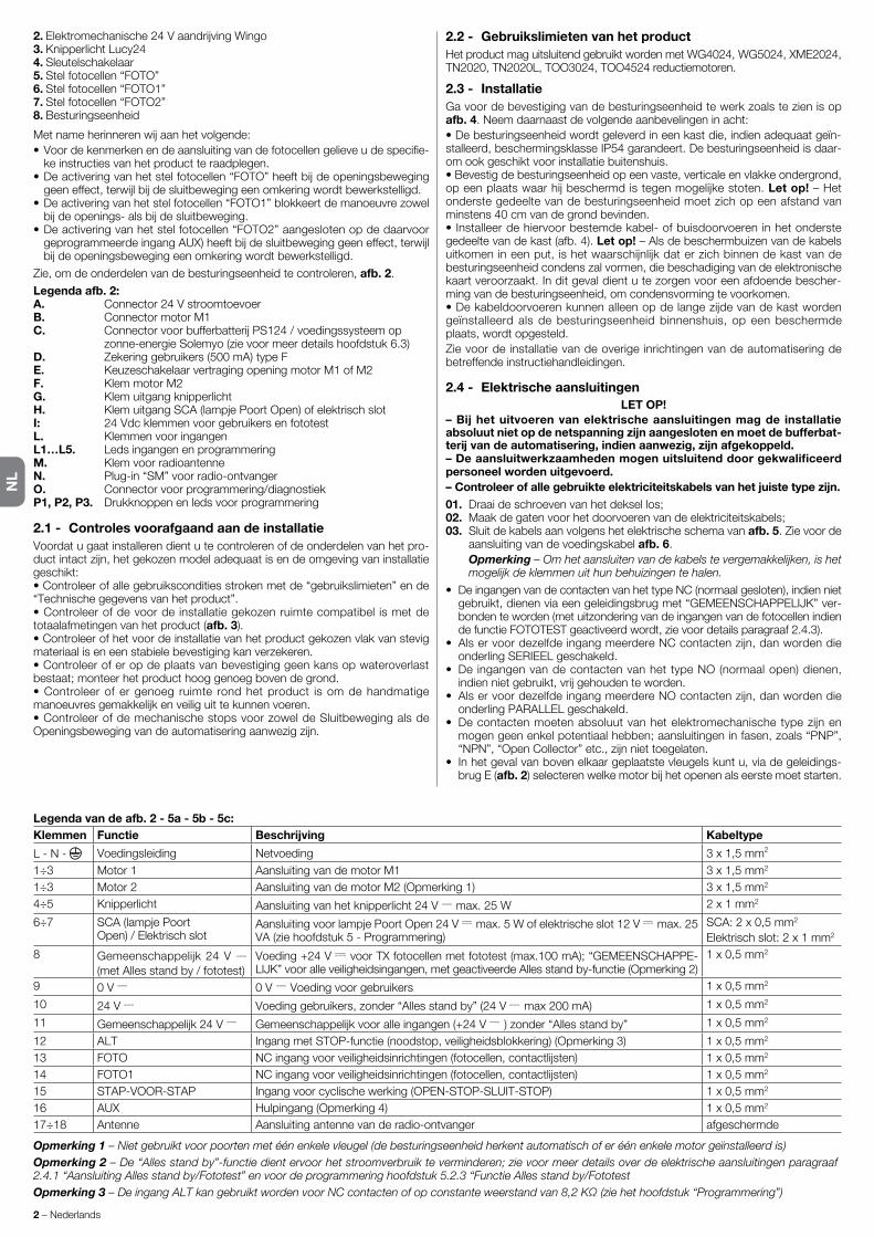
NL
2 – Nederlands
2.Elektromechanische24VaandrijvingWingo3. Knipperlicht Lucy244. Sleutelschakelaar5.Stelfotocellen“FOTO”6.Stelfotocellen“FOTO1”7.Stelfotocellen“FOTO2”8. Besturingseenheid
Metnameherinnerenwijaanhetvolgende:•Voordekenmerkenendeaansluitingvandefotocellengelieveudespecifie-
ke instructies van het product te raadplegen.•Deactiveringvanhetstelfotocellen“FOTO”heeftbijdeopeningsbeweginggeeneffect,terwijlbijdesluitbewegingeenomkeringwordtbewerkstelligd.
•Deactiveringvanhetstelfotocellen“FOTO1”blokkeertdemanoeuvrezowelbijdeopenings-alsbijdesluitbeweging.
•Deactiveringvanhetstelfotocellen“FOTO2”aangeslotenopdedaarvoorgeprogrammeerdeingangAUX)heeftbijdesluitbeweginggeeneffect,terwijlbijdeopeningsbewegingeenomkeringwordtbewerkstelligd.
Zie,omdeonderdelenvandebesturingseenheidtecontroleren,afb. 2.
Legenda afb. 2:A. Connector24VstroomtoevoerB. ConnectormotorM1C. ConnectorvoorbufferbatterijPS124/voedingssysteemop zonne-energieSolemyo(zievoormeerdetailshoofdstuk6.3)D. Zekeringgebruikers(500mA)typeFE. KeuzeschakelaarvertragingopeningmotorM1ofM2F. Klem motor M2G. Klem uitgang knipperlichtH. KlemuitgangSCA(lampjePoortOpen)ofelektrischslotI: 24VdcklemmenvoorgebruikersenfototestL. Klemmen voor ingangen L1…L5. Leds ingangen en programmeringM. Klem voor radioantenneN. Plug-in “SM” voor radio-ontvangerO. Connectorvoorprogrammering/diagnostiekP1, P2, P3. Drukknoppen en leds voor programmering
2.1 - Controles voorafgaand aan de installatieVoordatugaatinstallerendientutecontrolerenofdeonderdelenvanhetpro-ductintactzijn,hetgekozenmodeladequaatisendeomgevingvaninstallatiegeschikt:• Controleer of alle gebruikscondities stroken met de “gebruikslimieten” en de “Technischegegevensvanhetproduct”.• Controleer of de voor de installatie gekozen ruimte compatibel is met de totaalafmetingen van het product (afb. 3).• Controleer of het voor de installatie van het product gekozen vlak van stevig materiaal is en een stabiele bevestiging kan verzekeren.• Controleer of er op de plaats van bevestiging geen kans op wateroverlast bestaat;monteerhetproducthooggenoegbovendegrond.• Controleer of er genoeg ruimte rond het product is om de handmatige manoeuvresgemakkelijkenveiliguittekunnenvoeren.• Controleer of de mechanische stops voor zowel de Sluitbeweging als de Openingsbewegingvandeautomatiseringaanwezigzijn.
2.2 - Gebruikslimieten van het productHet product mag uitsluitend gebruikt worden met WG4024,WG5024,XME2024,TN2020,TN2020L,TOO3024,TOO4524 reductiemotoren.
2.3 - InstallatieGa voor de bevestiging van de besturingseenheid te werk zoals te zien is op afb. 4. Neem daarnaast de volgende aanbevelingen in acht:• De besturingseenheid wordt geleverd in een kast die, indien adequaat geïn-stalleerd,beschermingsklasseIP54garandeert.Debesturingseenheidisdaar-om ook geschikt voor installatie buitenshuis.• Bevestig de besturingseenheid op een vaste, verticale en vlakke ondergrond, opeenplaatswaarhijbeschermdistegenmogelijkestoten.Let op! – Het onderste gedeelte van de besturingseenheid moet zich op een afstand van minstens40cmvandegrondbevinden.• Installeer de hiervoor bestemde kabel- of buisdoorvoeren in het onderste gedeeltevandekast(afb.4).Let op! – Als de beschermbuizen van de kabels uitkomenineenput,ishetwaarschijnlijkdaterzichbinnendekastvandebesturingseenheid condens zal vormen, die beschadiging van de elektronische kaart veroorzaakt. In dit geval dient u te zorgen voor een afdoende bescher-ming van de besturingseenheid, om condensvorming te voorkomen.•Dekabeldoorvoerenkunnenalleenopdelangezijdevandekastwordengeïnstalleerd als de besturingseenheid binnenshuis, op een beschermde plaats, wordt opgesteld.Zievoordeinstallatievandeoverigeinrichtingenvandeautomatiseringdebetreffende instructiehandleidingen.
2.4 - Elektrische aansluitingenLET OP!
– Bij het uitvoeren van elektrische aansluitingen mag de installatie absoluut niet op de netspanning zijn aangesloten en moet de bufferbat-terij van de automatisering, indien aanwezig, zijn afgekoppeld.– De aansluitwerkzaamheden mogen uitsluitend door gekwalificeerd personeel worden uitgevoerd.– Controleer of alle gebruikte elektriciteitskabels van het juiste type zijn.01. Draaideschroevenvanhetdeksellos;02. Maakdegatenvoorhetdoorvoerenvandeelektriciteitskabels;03. Sluit de kabels aan volgens het elektrische schema van afb. 5.Zievoorde
aansluiting van de voedingskabel afb. 6. Opmerking – Om het aansluiten van de kabels te vergemakkelijken, is het
mogelijk de klemmen uit hun behuizingen te halen.
• DeingangenvandecontactenvanhettypeNC(normaalgesloten),indiennietgebruikt,dienenviaeengeleidingsbrugmet“GEMEENSCHAPPELIJK”ver-bonden te worden (met uitzondering van de ingangen van de fotocellen indien defunctieFOTOTESTgeactiveerdwordt,zievoordetailsparagraaf2.4.3).
• AlservoordezelfdeingangmeerdereNCcontactenzijn,danwordendieonderling SERIEEL geschakeld.
• De ingangenvandecontactenvanhettypeNO(normaalopen)dienen,indiennietgebruikt,vrijgehoudenteworden.
• AlservoordezelfdeingangmeerdereNOcontactenzijn,danwordendieonderling PARALLEL geschakeld.
• Decontactenmoetenabsoluutvanhetelektromechanischetypezijnenmogengeenenkelpotentiaalhebben;aansluitingeninfasen,zoals“PNP”,“NPN”,“OpenCollector”etc.,zijnniettoegelaten.
• In het geval van boven elkaar geplaatste vleugels kunt u, via de geleidings-brug E (afb. 2)selecterenwelkemotorbijhetopenenalseerstemoetstarten.
Legenda van de afb. 2 - 5a - 5b - 5c:Klemmen Functie Beschrijving Kabeltype
L - N - Voedingsleiding Netvoeding 3x1,5mm2
1÷3 Motor1 AansluitingvandemotorM1 3x1,5mm2
1÷3 Motor 2 AansluitingvandemotorM2(Opmerking1) 3x1,5mm2
4÷5 Knipperlicht Aansluitingvanhetknipperlicht24V max.25W 2x1mm2
6÷7 SCA (lampje PoortOpen)/Elektrischslot
AansluitingvoorlampjePoortOpen24V max.5Wofelektrischeslot12V max.25VA(ziehoofdstuk5-Programmering)
SCA:2x0,5mm2 Elektrischslot:2x1mm2
8 Gemeenschappelijk24V (metAllesstandby/fototest)
Voeding+24V voorTXfotocellenmetfototest(max.100mA);“GEMEENSCHAPPE-LIJK”vooralleveiligheidsingangen,metgeactiveerdeAllesstandby-functie(Opmerking2)
1x0,5mm2
9 0V 0V Voedingvoorgebruikers 1x0,5mm2
10 24V Voedinggebruikers,zonder“Allesstandby”(24V max200mA) 1x0,5mm2
11 Gemeenschappelijk24V Gemeenschappelijkvooralleingangen(+24V )zonder“Allesstandby” 1x0,5mm2
12 ALT IngangmetSTOP-functie(noodstop,veiligheidsblokkering)(Opmerking3) 1x0,5mm2
13 FOTO NCingangvoorveiligheidsinrichtingen(fotocellen,contactlijsten) 1x0,5mm2
14 FOTO1 NCingangvoorveiligheidsinrichtingen(fotocellen,contactlijsten) 1x0,5mm2
15 STAP-VOOR-STAP Ingangvoorcyclischewerking(OPEN-STOP-SLUIT-STOP) 1x0,5mm2
16 AUX Hulpingang(Opmerking4) 1x0,5mm2
17÷18 Antenne Aansluiting antenne van de radio-ontvanger afgeschermde
Opmerking 1 – Niet gebruikt voor poorten met één enkele vleugel (de besturingseenheid herkent automatisch of er één enkele motor geïnstalleerd is)Opmerking 2 – De “Alles stand by”-functie dient ervoor het stroomverbruik te verminderen; zie voor meer details over de elektrische aansluitingen paragraaf 2 .4 .1 “Aansluiting Alles stand by/Fototest” en voor de programmering hoofdstuk 5 .2 .3 “Functie Alles stand by/FototestOpmerking 3 – De ingang ALT kan gebruikt worden voor NC contacten of op constante weerstand van 8,2 KΩ (zie het hoofdstuk “Programmering”)

NL
Nederlands – 3
1e inrichting type:
NO NC 8,2 KΩ
NO Parallelschakeling (opmerking 2) Parallelschakeling (opmerking 1)
NC (opmerking 2) Serieschakeling Serieschakeling (opmerking 3)
8,2KΩ Parallelschakeling Serieschakeling (opmerking 4)
TABEL 1
2e in
richt
ing
type
:
2.4.1 - Opmerkingen over de aansluitingenHet merendeel van de aansluitingen is uiterst eenvoudig, voor een groot deel betrefthetrechtstreekseaansluitingenopéénenkelegebruikerofcontact.Oponderstaandeafbeeldingenzijnenkelevoorbeeldengegevenoverhoeuexter-ne inrichtingen dient aan te sluiten:
• Aansluiting Alles stand by / FototestDe“Allesstandby”-functiesisstandaardactief;defunctiewordtalleenauto-matisch uitgesloten wanneer de functie Fototest geactiveerd wordt. Opmer-king - De functies Stand-by en Fototest kunnen alleen om de beurt actief zijn, de ene functie sluit de andere namelijk uit.De“Allesstandby”-functiemaakthetmogelijkhetstroomverbruikteverminde-ren;erzijndriesoortenaansluitingenmogelijk:- met ““Alles stand by” actief (energiebesparing);ziehetschakelschemavan
afb. 5a-standaardaansluiting:zonder“Allesstandby”enzonder“fototest”;ziehet
schakelschema van afb. 5b-zonder“Allesstandby”enmet“fototest”;ziehetschakelschemavanafb. 5cMetgeactiveerde“Allesstandby”-functiezaldebesturingseenheid,1minuutnahetbeëindigenvaneenmanoeuvre,in“Allesstandby”schakelen;hierbijworden alle ingangen en uitgangen uitgeschakeld, om zo stroom te besparen. Dezestatuswordtgesignaleerddoordeled“OK”dielangzamergaatknippe-ren. WAARSCHUWING - Als de besturingseenheid wordt gevoed met een zonnepaneel(“Solemyo”-systeem)ofbufferbatterij,ishetnoodzakelijkde“Allesstand by”-functie te activeren zoals in het schakelschema van afb. 5a.Wanneerde“Allesstandby”-functienietnodigis,kande“Fototest”-functiegeactiveerd worden. Hiermee kunt u aan het begin van een manoeuvre contro-lerenofdeaangeslotenfotocellencorrectwerken.Omdezefunctietegebrui-ken dient u eerst de fotocellen correct aan te sluiten (zie schakelschema van afb. 5c)envervolgensdefunctieteactiveren.Opmerking – Als u de fototest activeert, zijn de aan de testprocedure onder-worpen ingangen FOTO, FOTO1 en FOTO2 . Als één van deze ingangen niet wordt gebruikt, moet deze op de klem 8 aangesloten worden .
• Aansluiting sleutelschakelaarVoorbeeld 1 (afb. 7a): DekeuzeschakelaaraansluitenomdefunctiesSTAP-VOOR-STAPenALTuittevoeren.Voorbeeld 2 (afb. 7b): DesleutelschakelaaraansluitenomdefunctiesSTAP-VOOR-STAPenéénvandevoordehulpingangvoorzienefuncties (OPENGEDEELTELIJK,ALLEENOPENEN,ALLEENSLUITEN...)uittevoeren.Opmerking – Zie voor de elektrische aansluitingen met geactiveerde “Stand By”-functie “Functie Alles stand by/Fototest” in deze paragraaf 2 .4 .1 .
• Aansluiting lampje Poort Open / Elektrische slot (afb. 8)AlsdeSCA(lampjePoortOpen)geprogrammeerdis,kandeuitganggebruiktwordenalslampjePoortOpen.Hetlampjeknippertlangzaamgedurendedeopeningsbewegingensnelbijdesluitbeweging;hetbrandtvastbijstilstaandegeopende poort en is uit wanneer de poort gesloten is. Als de uitgang gepro-grammeerdisalselektrischslot,wordthijbijiederbeginvaneenopeningsma-noeuvre 3 seconden lang geactiveerd.
2.4.2 - Typologie ingang ALTDe besturingseenheid MC424 kan geprogrammeerd worden voor twee soor-tenALT-ingangen:- Alt type NC voor aansluiting op contacten van het type NC.- Alt met constante weerstand. Hiermee kunt u inrichtingen met een uit-gangmetconstanteweerstand8,2KΩ(bijv.contactlijsten)opdebesturing-seenheid aansluiten. De ingang meet de waarde van de weerstand en trekt toestemming voor de manoeuvre in wanneer de weerstand buiten het nomi-nale bereik komt. Met de juiste aanpassingen kunt u op de Alt-ingang met constanteweerstandookinrichtingenmetnormaalgeopende(“NO”)contac-ten,normaalgesloten(“NC”)contacteneneventueelmeerdanééninrichting,ookvanverschillendtype,aansluiten,zieTabel1.
LET OP! – Als de Alt-ingang met constante weerstand gebruikt wordt om inrichtingen met veiligheidsfuncties aan te sluiten, garanderen
Opmerkingen bij Tabel 1:Opmerking 1 – Eén of meerdere NO inrichtingen kunnen zonder enige beperking van het aantal inrichtingen onderling parallel geschakeld worden met een eind-weerstand van 8,2 KΩ (afb. 9a) . Zie voor de elektrische aansluitingen met geac-tiveerde “Stand By”-functie “Functie Stand By/Fototest” in deze paragraaf 2 .4 .1 .Opmerking 2 – De combinatie NO en NC is mogelijk door de 2 contacten onderling parallel te schakelen waarbij in serie met het NC contact een weer-stand van 8,2 KΩ geschakeld moet worden ((ook de combinatie van 3 inrichtin-gen: NO, NC en 8,2 KΩ is dus mogelijk (afb. 9b) .Opmerking 3 – Eén of meer NC inrichtingen kunnen onderling in serie en met een weerstand van 8,2KΩ worden verbonden zonder enige beperking van het aantal inrichtingen (afb. 9c) .Opmerking 4 – Alleen een inrichting met een uitgang met constante weer-stand 8,2 KΩ kan aangesloten worden; eventueel moeten meerdere inrichtin-gen “in cascadeschakeling” met een enkele eind- weerstand van 8,2 KΩ aan-gesloten worden (afb. 9d) .
2.5 - Eerste inschakeling en controle van de aansluitingenLET OP! – De aansluitwerkzaamheden mogen uitsluitend door gekwali-ficeerd personeel worden uitgevoerd.Na stroom aan de besturingseenheid te hebben gegeven, dient u te controle-renofalleledsgedurendeenkelesecondensnelknipperen.Voervervolgensdevolgende controles uit:1.Controleerofopdeklemmen9-10eenspanningvanongeveer30Vdcstaat;
alsdatniethetgevalis,sluitdestroomvoorzieningdanonmiddellijkafencontroleerde aansluitingen en de spanning van de stroomvoorziening beter.
2.Naeerstsnelgeknipperdtehebben,signaleertdeledP1datdebesturing-seenheid correct functioneert door regelmatig te knipperen, met tussen-pozenvaneenseconde.Wanneerereenvariatieopdeingangenis,zaldeLED“P1”tweemaalsnelknipperenwaarmeeaangegevenwordtdatdeingang herkend is.
3.Alsdeaansluitingencorrectzijn,moetendedesbetreffendeledsvandeingangenvanhettype“NC”branden,terwijldebijdeingangenvanhettype“NO”horendeledsuitmoetenzijn.Zieafb. A en Tabel 2.
A
TABEL 2INGANG TYPE INGANG STATUS LEDALT ALTNC L1aan ALTWEERSTAND L1aan CONTANTE8,2KΩFOTO NC L2aanFOTO1 NC L3aanP.P. NO L4uitAUX OPENGEDEELTELIJKtype1-NO L5uit OPENGEDEELTELIJKtype2-NO L5uit ALLEENOPENEN-NO L5uit ALLEENSLUITEN-NO L5uit FOTO2-NC L5aan
4. Verifieerdat,wanneerudeinrichtingenactiveertdieopdeingangenaange-slotenzijn,dedesbetreffendeledsuitgaanofgaanbranden.
5.Verifieerdat,wanneeruoptoetsP2drukt,beidemotoreneenkorteope-ningsmanoeuvreuitvoerenwaarbijdemotorvandebovenstevleugelalseerstestart.Onderbreekdemanoeuvredooropnieuwop toetsP2 tedrukken.Alsdemotorbijhetopenennietstarten,dientudepolenvandemotorkabels om te draaien. Als de eerste motor die start niet de motor van de bovenste vleugel is, dient u de geleidingsbrug E (afb. 2)omtezetten.
2.6 - Automatisch zoeken van de eindaanslagenNaafloopvandecontroleskuntbeginnenmethetautomatischzoekenvande
Functie Type ingang BeschrijvingOPENGEDEELTELIJKTYPE1 NO De bovenste vleugel gaat helemaal openOPENGEDEELTELIJKTYPE2 NO De 2 vleugels gaan half openOPEN NO Alleen de openingsmanoeuvre wordt uitgevoerdSLUIT NO Alleen de sluitmanoeuvre wordt uitgevoerdFOTO2 NC FunctieFOTO2UITGESLOTEN -- Geen enkele functie
Opmerking 4 – In de fabriek is de hulpingang AUX geprogrammeerd met de functie “Open gedeeltelijk type 1”, maar deze ingang kan ook met één van de volgende functies geprogrammeerd worden:
alleen de inrichtingen met uitgang met constante weerstand 8,2 KΩ de veiligheidscategorie 3 tegen storingen.

NL
4 – Nederlands
mechanischestops;ditisnodigomdatdebesturingseenheidMC424deduurvan de openings- en sluitmanoeuvres moet “meten”. Deze procedure is geheel automatisch en baseert zich op het meten van de belasting van de motoren om demechanischestopsbijopeningensluitingtedetecteren.Let op! - Als deze procedure reeds is uitgevoerd dient u, om deze opnieuw te activeren, eerst het geheugen te wissen (zie hoofdstuk “Wissen van het geheugen”). Om te controleren of het geheugen de parameters van de ein-daanslagen bevat, eerst de stroomvoorziening van de besturingseenheid uit- en vervolgens weer inschakelen. Als alle leds ongeveer 6 seconden snel knipperen is het geheugen leeg; als ze maar 3 seconden knipperen,-bevat het geheugen de parameters van de eindaanslagen reeds.
Alvorens met het zoeken van de eindaanslagen te beginnen dient u te controle-renofalleveiligheidsinrichtingenhuntoestemmingdaarvoorgeven(ALT,FOTOenFOTO1geactiveerd).Activeringvaneenveiligheidsinrichtingofhetbinnen-komenvaneenbedieningsinstructietijdensdeprocedureheefttotgevolgdatdezeonmiddellijkonderbrokenwordt.De vleugels MOETEN ongeveer hal-verwege hun bewegingstraject staan.Procedure – Druk op de knop P2 (afb. 2) om de zoekfase te starten. Deze fase bestaat uit:- Korte openingsbeweging van beide motoren.- Sluitbeweging van de motor van de onderste vleugel tot aan de mechanische
stop van de sluitbeweging.- Sluitbeweging van de motor van de bovenste vleugel tot aan de mechani-
sche stop van de sluitbeweging.- Begin openingsbeweging van de motor van de bovenste vleugel.- Nahetvoorzienefaseverschil(vertraging),beginopeningsbewegingvande
onderste vleugel. Als de vertraging niet voldoende is, dient u het zoeken te onderbrekenmetdetoetsP1(afb. 2),envervolgensdetijdsinstellingtever-anderen(ziehoofdstuk5).
- De besturingseenheid meet de beweging die nodig is om de motoren de mechanische stops van de openingsbeweging te laten bereiken.
- Complete sluitmanoeuvre. De motoren kunnen op verschillende momenten starten,hetdoelhiervanisbijhetbereikenvandegeslotenstandeenfase-verschil(vertraging)tehandhavendievolstaatomhetgevaarvoorinterferen-tietussendevleugelstevermijden.
- Einde van de procedure met opslag in het geheugen van alle verrichte metingen.
Al deze fasen worden de een na de ander uitgevoerd, zonder dat de gebruiker iets hoeft te doen. Als de procedure om welke reden dan ook niet goed ver-loopt,dientuhemteonderbrekendooropdetoetsP1tedrukken.Vervolgensherhaaltudeprocedure,waarbijueventueelparameterswijzigt,bijvoorbeelddeactiveringsdrempelvandestroommeting(ziehoofdstuk5).
Ditzijndebelangrijkstefasenbijdeaanlegvandeautomatiseringteneindeeenzogrootmogelijkeveiligheidvandeinstallatietegaranderen.Deeindtestkanook gebruikt worden om de inrichtingen, waaruit de automatisering is opgebo-uwd,periodiektecontroleren.Defasenvandeeindtestendeinbedrijfstellingvandeautomatiseringmoetenwordenuitgevoerddoorgekwalificeerdenervarenpersoneel dat dient te bepalen welke tests in functie van de bestaande risico’s noodzakelijkzijnentecontrolerenofdewettelijkevoorschriften,normenenre-gelsenmetnameallevereistenvannormEN12445,diedetestmethodesvoordecontrolevanautomatiseringenvoorpoortenbepaalt,inachtgenomenzijn.De extra of optionele inrichtingen moeten worden onderworpen aan een speci-fiekeeindtest,zowelvoorwatbetreftdewerkingalsvoorwatbetreftdejuisteinteractiemetdeMC424;raadpleegdeinstructiehandleidingenvandeafzon-derlijkeinrichtingen.
3.1 - EindtestDe reeks van tests heeft betrekking op de besturingseenheid die geprogram-meerdismetdevooringesteldefuncties,zieparagraaf5.1:•Controleerofdeactiveringvande ingangSTAP-VOOR-STAPde reeks“Open,Stop,Sluit,Stop”activeert.
•ControleerofdeactiveringvandeingangAUX(functiegedeeltelijkopenenType1)dereeks:Open,Stop,Sluit,Stop”vanalleendemotorvandeboven-stevleugelaanstuurt,terwijldemotorvandeonderstevleugelingeslotenstandblijftstaan.
• Laat een openingsmanoeuvre van start gaan en controleer of het volgende gebeurt:
- bijhetafdekkenvanFOTOzetdepoortdeopeningsmanoeuvrevoort.- bijhetafdekkenvanFOTO1stoptdemanoeuvretotdatFOTO1weervrijis,
daarna wordt de openingsmanoeuvre voortgezet.- IndienFOTO2geïnstalleerd is,moetdemanoeuvrenadatdezeinrichting
afgedekt is, stoppen en moet de poort naar gesloten stand teruglopen.• Controleer of, wanneer de vleugel de mechanische stop van de openingsbe-
weging bereikt,de motoren worden uitgeschakeld.• Laat een sluitmanoeuvre van start gaan en controleer het volgende:- bijhetafdekkenvanFOTOstoptdemanoeuvrestoptdemanoeuvretotdatFOTO1weervrijis.
- bijhetafdekkenvanFOTO1stoptdemanoeuvretotdatFOTO1weervrijis,en wordt de manoeuvre vervolgens voortgezet in openingsrichting.
- bijhetafdekkenvanFOTO2zetdepoortdesluitmanoeuvrevoort.•ControleerofdestopinrichtingendiezijnverbondenmetdeingangALTiede-rebewegingonmiddellijkstopzetten.
• Controleer of het niveau van het obstakeldetectiesysteem geschikt is voor de toepassing:
EINDTEST EN INBEDRIJFSTELLING3
- Verhindergedurendedemanoeuvre(zowelbijhetopenenalsbijhetsluiten)de beweging van de vleugel om een obstakel te simuleren en controleer of de manoeuvre wordt omgekeerd voordat de door de normen voorgeschreven kracht wordt overschreden.
•Afhankelijkvandemetdeingangenverbondeninrichtingenkunnenernoganderecontrolesvereistzijn.
Let op – Als er gedurende 2 achtereenvolgende manoeuvres in dezelf-de richting een obstakel wordt gedetecteerd, zal de besturingseenheid een gedeeltelijke omkering van beide motoren uitvoeren die slechts 1 seconde duurt. Bij de volgende bedieningsinstructie starten de vleugels in de openingsrichting en wordt de eerste activering van de stroomme-ting voor elke motor beschouwd als mechanische stop bij de openings-beweging. De automatisering gedraagt zich op dezelfde manier als bij een hervatting van de netvoeding: de eerste instructie is altijd voor een openingsmanoeuvre en het eerste obstakel wordt altijd beschouwd als mechanische stop bij de openingsbeweging.
3.2 - InbedrijfstellingInbedrijfstelling kan alleen plaatsvinden nadat alle fasen van de eind-test met succes zijn afgesloten.1 Maak een technisch dossier van de automatisering, dat de volgende docu-
menten moet omvatten: een overzichtstekening van de automatisering, het schema van de tot stand gebrachte elektrische aansluitingen, de risicoana-lyse en de toegepaste oplossingen (zie op de site www.niceforyou.com deformulierendiemoetenwordeningevuld),deverklaringvanovereen-stemming van de fabrikant van alle gebruikte inrichtingen en de door de installateur ingevulde verklaring van overeenstemming.
2 Breng een plaatje op de poort aan met daarop tenminste de volgende ge-gevens: type automatisering, naam en adres van de fabrikant (verantwoor-delijkvoorde“inbedrijfstelling”),serienummer,bouwjaaren“CE”-keurmerk.
3 Alvorensdeautomatiseringinbedrijftestellen,dientudeeigenaarafdoen-deteinformerenoverdegevarenenrestrisico’sdienogaanwezigzijn.
De led Diagnostiek P2 (afb. 2)signaleerteventuelestoringenofongewonegedragingendiedoordebesturingseenheidtijdensdemanoeuvregeconsta-teerd worden.Het soort probleem wordt door een reeks met een bepaald aantal knipperingen aangegevenendezesignaleringblijfttotdevolgendemanoeuvreactief.Hiervolgt een overzichtstabel:
Aantal Soort storingKnipperingen led P2 1 ActiveringstroommetingM1
2 Activering stroommeting M2
3 ActiveringingangALTtijdensdemanoeuvre
4 Fout Fototest
5 OverstroomuitgangSCAofelektrischslot
DIAGNOSTIEK4
De besturingseenheid MC424 beschikt over enkele programmeerbare functies. Dezefunctieswordenvooringesteldineenstandaardconfiguratiedievoorhetgrootste deel van de automatiseringen voldoende geschikt is. Deze functies kunnenopelkgewenstmomentgewijzigdworden,zowelvooralsnadeauto-matische zoekfase van de eindaanslagen, via een speciale programmerings-procedure;zieparagraaf5.3.
5.1 - Vooringestelde functies• Beweging motoren: snel• Automatisch sluiten: actief•Woonblok: gedeactiveerd•Voorwaarschuwing: gedeactiveerd• Sluit na foto: gedeactiveerd•Vertragingbijopenen: niveau2(10%)•Allesstandby/Fototest: Allesstandby•SCA/Elektrischslot: SCA• IngangALT: typeNC•Zwarepoorten: gedeactiveerd• SCA proportioneel: gedeactiveerd•Pauzeduur: 20seconden•Hulpingang: gedeeltelijkeopeningType1(activeertalleende motorvandebovenstevleugel)
• Gevoeligheid stroommeting: Klasse 2
5.2 - Programmeerbare functiesOpdatdeinstallatiebeteraansluitopdeeisenvandegebruikerenveiligerisbijdeverschillendegebruikscondities,bestaatdemogelijkheidviadebesturing-seenheid MC424 bepaalde functies of parameters en de functie van bepaalde ingangen en uitgangen programmeren.
PROGRAMMERING5

NL
Nederlands – 5
5.2.1 - Directe programmering• Langzame/snelle beweging: Hetisopelkwillekeurigmomentmogelijkdebewegingssnelheidvandepoorttekiezen(metstilstaandemotor),hiervoorge-bruikt u de toets P3 (afb. 2)wanneerdecentralezichnietineenprogramme-erstatus bevindt. Als de led P3 uit is, betekent dit dat de langzame beweging is ingesteld, als de led brandt betekent dit dat de hoge snelheid is ingesteld.
5.2.2 - Programmering eerste niveau: eerste deel• Automatisch sluiten: metdezefunctiewordtdepoortnaafloopvandegeprogrammeerdepauzeduurautomatischgesloten,aanvankelijkisdepau-zeduuringesteldop20secondenmaarditkanin5,10,20,40of80secondengewijzigdworden.
Als de functie niet wordt geactiveerd, is het gedrag van de poort “semi-auto-matisch”.
• Functie “Woonblok”: dezefunctieisnuttigwanneererveelmensenzijndiede installatie met een afstandbediening gebruiken. Als deze functie geactive-erd is, veroorzaakt elke ontvangen bedieningsinstructie een openingsma-noeuvre die niet door verdere bedieningsimpulsen onderbroken kan wor-den. Als de functie niet geactiveerd is, veroorzaakt een bedieningsinstructie OPEN-STOP-SLUIT-STOP.
• Voorwaarschuwing: Met deze functie kan het waarschuwingslicht geacti-veerd worden voordat de manoeuvre van start gaat, het licht wordt 3 secon-den ingeschakeld.
Als de functie niet wordt geactiveerd, gaat het waarschuwingslicht knipperen als de manoeuvre van start gaat.
• Sluit na foto: in geval van automatische sluiting kunt u met deze functie de pauzeduurop4secondenterugbrengennadatdefotocelFOTOisvrijge-maakt, dat wil zeggen de poort sluit 4 seconden nadat de gebruiker er door-heen is gegaan. Als de functie niet wordt geactiveerd, heeft de pauzeduur de geprogrammeerde duur.
• Vertraging bij openen: metdezefunctieverkrijgtubijhetopeneneenver-traging in de activering van de onderste vleugel ten opzichte van de bovenste vleugel om te voorkomen dat de vleugels tegen elkaar kunnen slaan. Het faseverschilbijhetsluitenisaltijdaanwezigenwordtautomatischdoordebesturingseenheidberekendomaltijdhetzelfdegeprogrammeerdefasever-schilbijhetopenenteverkrijgen.
5.2.3 - Programmering eerste niveau: tweede deel• Functie Alles stand by / Fototest: op de besturingseenheid is de functie “Allesstandby”vooringesteld;alsdezefunctieactief iszaldebesturing-seenheid1minuutnaafloopvaneenmanoeuvredeuitgang“Allesstandby”(klem8),alleingangenendeandereuitgangenuitschakelenomhetstroom-verbruik te beperken (zie het schakelschema van afb. 5a).Dezefunctieisverplicht indien de besturingseenheid uitsluitend via Solemyo zonnepanelen wordt gevoed. De functie wordt ook aanbevolen wanneer de besturingseen-heid via het elektriciteitsnet wordt gevoed en u de werking op noodvoeding (bufferbatterijPS124)wiltverhogen.Alsalternatiefvoor“Allesstandby”kande functie “Fototest” worden geactiveerd: deze functie controleert aan het beginvaneenmanoeuvreofdeaangeslotenfotocellencorrectwerken.Omdeze functie te gebruiken, dient u de fotocellen correct aan te sluiten (zie schakelschema van afb. 5c)envervolgensdefunctieteactiveren.
• Uitgang lampje Poort Open / Elektrisch slot: als de functie wordt geactive-erd, kunnen de klemmen 6-7 gebruikt worden om het elektrische slot aan te sluiten. Als de functie niet wordt geactiveerd, kunnen de klemmen 6-7 ge bruikt wordenvooraansluitingvaneencontrolelampjevoorpoortopen(24V).
• Ingang ALT van het type NC of met Constante weerstand: als de func-tiewordtgeactiveerd,wordtdeALTingangop“Constanteweerstand8.2KΩ”ingesteld,inditgevalmoeter,omtoestemmingvoordemanoeuvretegeven,tussendegemeenschappelijkegeleiderendeingangeenweerstandvan8.2KΩ+/-25%aanwezigzijn.Alsdefunctienietisingesteld,wordtdeingangALTgeconfigureerdomtewerkenmetcontactenvanhettypeNC.
• Lichte/zware poorten: als de functie wordt geactiveerd, kan de besturingseen-heid ook zware poorten aansturen door de versnelling en de vertragingssnelheid bijhetsluitenopeenanderemanierintestellen.Alsdefunctienietwordtgeacti-veerd, is de besturingseenheid ingesteld om lichte poorten aan te sturen.
• SCA proportioneel: als deze functie wordt geactiveerd, is de uitgang SCA opproportioneelknippereningesteld,ofwelbijdeopeningsmanoeuvregaatdelampsteedssnellerknipperennaarmatedevleugelsdichterbijdeope-ningseindaanslagenkomen,daarentegenwordtbijdesluitmanoeuvrehetknipperenminderintensiefalnaargelangdevleugelsdichterbijdesluiting-seindaanslagen komen. Als de functie niet wordt geactiveerd, knippert het lichtlangzaambijhetopenenensnelbijhetsluiten.
5.2.4 - Functies tweede niveau• Pauzeduur: depauzeduur,ofteweldetijddieverstrijkttussenheteindevan
een openingsmanoeuvre en het begin van de automatische sluiting, kan op 5,10,20,40en80secondengeprogrammeerdworden.
• Hulpingang AUX: De besturingseenheid heeft een hulpingang die kan wor-dengeconfigureerdvooréénvandevolgende6functies:
- Gedeeltelijk openen type 1: deze voert dezelfde functie als de ingang STAP-VOOR-STAP uit en veroorzaakt alleen de opening van de bovenste vleugel . Deze functie werkt alleen als de poort helemaal dicht is, anders wordt ze geïnterpreteerd alsof het een bedieningsinstructie STAP-VOOR-STAP was .
- Gedeeltelijk openen type 2: deze voert dezelfde functie als de ingang STAP-VOOR-STAP uit en veroorzaakt de opening van de beide vleugels voor de helft van de tijd die voorzien is voor volledige opening. Deze functie werkt alleen als de poort helemaal dicht is, anders wordt ze geïnterpreteerd alsof het een bedieningsinstructie STAP-VOOR-STAP was .
- Alleen openen: deze ingang voert alleen de opening uit met de volgorde Open-Stop-Open-Stop
- Alleen sluiten: deze ingang voert alleen de sluiting uit met de volgorde Sluit-Stop-Sluit-Stop
- Foto 2: voert de functie van de veiligheidsinrichting “FOTO 2” uit - Uitgesloten: de ingang beheert geen enkele functie• Drukafvoertijd: naafloopvandesluitmanoeuvre,nadatdevleugelsvolle-diggeslotenzijn,blokkeertdemotordevleugelsmeteengeprogrammeerdekracht. Meteen daarna wordt, als deze functie actief is, een zeer korte omke-ring van de beweging aangestuurd die ervoor dient de overtollige druk die de motor op de vleugels uitoefent af te voeren.
• Gevoeligheid stroommeting: de besturingseenheid beschikt over een sys-teem voor het meten van de door de twee motoren opgenomen stroom dat gebruikt wordt om de mechanische eindaanslagen en eventuele obstakels tijdensdebewegingvandepoorttedetecteren.Aangeziendeopgenomenstroom afhangt van verschillende omstandigheden (gewicht poort, allerlei soortenwrijvingen,windstoten,spanningsvariaties,etc..)iservoorzienineenmogelijkheiddeactiveringsdrempelteveranderen.Erzijn6niveausvoorzien:graad1isdegevoeligste(minimumkracht),graad6isdeminstgevoelige(maximumkracht).Doordegraadvanamperometrischegevoeligheidtever-hogenwordtdesnelheidvanvertragingtijdensdesluitmanoeuvreverhoogd.
LET OP! – De functie “stroommeting” kan, wanneer deze correct is afgesteld (in combinatie met andere noodzakelijke maatregelen) nut-tig zijn voor het in acht nemen van de Europese voorschriften, EN 12453 en EN 12445, die het gebruik van technieken of inrichtingen vereisen die tot doel hebben de krachten en het gevaar van bewegen-de automatische deuren en poorten te beperken.
• Vertraging vleugel: de vertraging in het starten van de motor van de onderste vleugelkanop5,10,20,30of40%vandebedrijfsduurgeprogrammeerdworden.
5.3 - ProgrammeermodiAlleinparagraaf5.2“Programmeerbarefuncties”beschrevenfunctieskunnenviaeen programmeringsfase geselecteerd worden. Aan het eind van deze fase wor-den de gemaakte keuzes in het geheugen opgeslagen. In de besturingseenheid zit een geheugen dat de functies en de parameters van de automatisering bewaart.VooralleprogrammeringsfasenwordendetoetsenP1P2enP3gebruikt,terwijlde5ledsL1,L2…L5degeselecteerdeparameteraangeven.Erzijn2programmeringsniveaus:•Opheteerste niveau kunt u de functies activeren of deactiveren. Elke Led L1,L2….L5behoortbijeenbepaaldefunctie;alsdeledbrandt,isdiefunctiegeactiveerd, als de led uit is, is die functie niet geactiveerd.
Het eerste niveau bestaat uit 2 delen welke u kunt selecteren door op toets P3 te drukken.DebijbehorendeLEDP3geeftaanwelkvande2delengeselecteerdis.
Eerste niveau (Led P1 brandt continu): tweede deel (led P3 aan)
LedL1 LedL2 LedL3 LedL4 LedL5Alles stand by Elektrisch slot Alt door Zware SCA Fototest weerstand poorten proportioneel
Eerste niveau (Led P1 brandt continu): eerste deel (led P3 uit)
LedL1 LedL2 LedL3 LedL4 LedL5Automatisch Functie Voorwaarschu- Sluit na Vertraging bijsluiten woonblok wing foto openen
Eerste niveau (Led P1 brandt continu): eerste deel (led P3 uit)
LedL1 LedL2 LedL3 LedL4 LedL5Automatisch Functie Voorwaarschu- Sluit na Vertraging bijsluiten woonblok wing foto openen
•Vanuitheteersteniveauvanheteerstedeelkuntuovergaannaarhettweede niveauwaarudebijdiefunctiebehorendeparameterkuntselecteren;elkeled komt met een andere aan de parameter te koppelen waarde overeen.
Tweede niveau:
Parameter: Parameter: Parameter: Parameter: Parameter:Pauze- Ingang AUX Drukafvoer- Gevoeligheid Vertragingduur tijd stroommeting vleugelL1:5s L1:Open L1:geen L1:Graad1 L1:5%s gedeeltelijkTYPE1 drukafvoer (gevoeliger)L2:10s L2:Open L2:0,3s L2:Graad2 L2:10% gedeeltelijkTYPE2
L3:20s L3:Alleen openen L3:0,7s L3:Graad3 L3:20%
L4:40s L4:Alleen sluiten L4:1,3s L4:Graad4 L4:30%
L5:80s L5:Foto2 L5:2s L5:Graad5 L5:40% (mindergevoelig)
Alle LEDs uit: Alle LEDs uit: ingang Graad 6 niet gebruikt (stroommeting max)
Eerste niveau (Led P1 brandt continu): tweede deel (led P3 aan)
LedL1 LedL2 LedL3 LedL4 LedL5Alles stand by Elektrisch slot Alt door Zware SCA Fototest weerstand poorten proportioneel

NL
6 – Nederlands
5.3.1 - Programmering eerste niveau: functiesOpheteersteniveaukuntudefunctiesactiverenofdeactiveren.OpheteersteniveauisdeledP1altijdaanengevendebrandendeledsL1,L2…L5deactievefuncties aan, terwijl de niet-brandende leds aangeven dat de functies niet actief
zijn.Deknipperendeledgeeftdegeselecteerdefunctieaan;alshetlampjesnelknippert betekent dit dat de functie niet actief is, als het lampje langzaam knip-pertisdefunctieactief.Omvanheteerstedeelvandeprogrammeringnaarnaarhet tweede deel over te gaan, en omgekeerd, dient u op toets P3 te drukken.
TABEL A1 - Oproepen van programmering eerste niveau
01. HouddetoetsenP1enP2tenminstegedurende3secondeningedrukt Snel knipperen van alle leds geeft aan dat de programmeermodus geactiveerd werd
TABEL A2 - Activeren of deactiveren van een functie
01. DrukmeermaalsopP1totdatdeknipperendeledopdegewenstefunctieisgekomen
02. Druk op P2 om deze functie te activeren of te deactiveren
TABEL A3 - Overgaan van eerste deel naar tweede deel van het eerste niveau (en omgekeerd)
01. Druk op de toets P3
TABEL A4 - Verlaten van het eerste niveau met bevestiging van de wijzigingen
01. HouddetoetsP1ingedruktenonmiddellijkdaarnadetoetsP2,enhoudbeidetoetsenminstens3secondeningedrukt
TABEL A5 - Verlaten van het eerste niveau met annulering van de wijzigingen
01. Druktenminste3secondenopP1,ofwacht1minuut,ofschakeldestroomvoorzieninguit
5.3.2 - Programmering tweede niveau: parametersOphettweedeniveaukuntudeparametersmetbetrekkingtotdefunctiesselecteren. U kunt alleen via het eerste naar het tweede niveau gaan.
OphettweedeniveauknippertdeledP1snel,terwijldeandere5ledsL1,L2...L5degeselecteerdeparameteraangeven.
TABEL B1 - Oproepen van programmering tweede niveau
01. Roepdeprogrammeringeersteniveauopdoortenminste3secondenopP1enP2tedrukken
02. SelecteerdefunctiedooropdetoetsP1tedrukkentotdatdeknipperendeledophetgewenstepuntstaat
03. Ga het tweede niveau binnen door de toets P2 tenminste 3 seconden ingedrukt te houden
TABEL B2 - Kiezen van een parameter
01. Druk meermaals op P2 totdat de led op de gewenste parameter is gekomen
TABEL B3 - Teruggaan naar het eerste niveau
01. DrukopdetoetsP1
TABEL B4 - Verlaten van het eerste niveau met bevestiging van de wijzigingen
01. HouddetoetsP1ingedruktenonmiddellijkdaarnadetoetsP2,enhoudbeidetoetsenminstens3secondeningedrukt
TABEL B5 - Verlaten van het eerste niveau met annulering van de wijzigingen
01. Druktenminste3secondenopP1,ofwacht1minuut,ofschakeldestroomvoorzieninguit
P1 P2
P1
P2
P3
P1 P2
3s of 60s
of
P1
3 s
3 sP1 P2
P1 P2
3s of 60s
of
P1
P1
P2
P1
P2 3 s

NL
Nederlands – 7
5.3.3 - Wissen van het geheugenBij elke nieuwe programmering worden de voorgaande instellingen vervangen, het is dus normaal gesproken niet nodig “alle parameters te wissen”. In elke ge val kunt u het geheugen helemaal wissen door onderstaande eenvoudige
handelingen te verrichten: LET OP – Nadat het geheugen is gewist keren alle functies op de vooraf ingestelde waarden terug en dient u opnieuw de eindaanslagen te zoeken.
5.3.4 - Voorbeeld van programmering eerste niveauIn deze voorbeelden laten wij u de stappen zien die noodzakelijk zijn om een functie op het eerste niveau te activeren of te deactiveren, bijvoorbeeld active-
ringvandefunctie“Woonblok”envoorbereidingvandeuitgang“SCA”omhetelektrische slot te activeren.
Voorbeeld van programmering eerste niveau:activeer de functie “Woonblok” en activeer de uitgang voor “elektrisch slot”
01. Roepdeprogrammeringeersteniveauopdoortenminste3secondenopP1enP2tedrukken
02. Druk1maalopP1totdatdeknipperendeledopled2staat(ledknippertsnel)
03. Activeerdefunctie“Woonblok”dooropP2tedrukken(ledknippertlangzaam)
04. DrukéénmaalopP3voorhetactiverenvandeeltwee(deledvanP3gaataan)
05. Druk1maalopP1omdeknipperendeledopled2tebrengen(ledknippertsnel)
06. Activeerdeuitgang“Elektrischslot”dooropP2tedrukken(ledknippertlangzaam)
07. Sluitdeprogrammeringaf,nadegegevenstehebbenopgeslagendoordetoetsP1ingedrukttehoudenen onmiddellijk daarna de toets P2, en beide toetsen minstens 3 seconden ingedrukt te houden
Voorbeeld van programmering van het tweede niveau: wijzigen van de “gevoeligheid van de stroommeting”
01. Roepdeprogrammeringeersteniveauopdoortenminste3secondenopP1enP2tedrukken
02. Druk3maalopP1totdatdeknipperendeledopled4komt
03. Ga naar het tweede niveau door tenminste 3 seconden op P2 te drukken
04. Druk3maalopP2totdatdeled5gaatbranden
05. GaterugnaarheteersteniveaudooropP1tedrukken
06. Sluitdeprogrammeringaf,nadegegevenstehebbenopgeslagendoordetoetsP1ingedrukttehoudenen onmiddellijk daarna de toets P2, en beide toetsen minstens 3 seconden ingedrukt te houden
5.3.5 - Voorbeeld van programmering tweede niveauIn dit voorbeeld laten wij u de stappen zien die noodzakelijk zijn om een para-
meterophettweedeniveautewijzigen;alsvoorbeeldwijzigenwedegevoeli-
gheidvandestroommetingop“niveau5”.
P1 P2
2P1
P2
P3
P2
P1 P2
2P1
3s
3s
x1
P1 P2
3s
3s
3s
4P1
5P2
P2
P1
P1 P2
x3
x3
TABEL C1 - Wissen van het geheugen
01. Schakel de stroomvoorziening naar de besturingseenheid uit en wacht totdat alle LED’s uit zijn (verwijdereventueeldezekeringF1)
02. DetweetoetsenP1P2opdekaarttegelijkertijdindrukkenenvasthoudenende stroomvoorziening naar de centrale weer inschakelen
03. LaatdetoetsenP1enP2naexact 3 seconden los
Alshetwissenvanhetgeheugentoteengoedeindeisgekomen,gaanalleleds1secondeuit;aksdeled’sblijvenknipperen,dientudeheleprocedurevoor wissen van het geheugen te herhalen.
3s
P1 P2
P1 P2
en

NL
8 – Nederlands
5.3.6 - ProgrammeerschemaOponderstaandeafbeeldingvindtuhetcompleteschemavoorprogramme-ringvandefunctiesendedaarbijhorendeparameters.Opdezeafbeelding
zijnookdefunctiesenparametersaangegevendieaanvankelijkofnavolledigwissenvanhetgeheugenvooringesteld(fabrieksinstelling)zijn.
STOP Foto Foto 1
Stap voor Stap
AUX
Normale Werking Led P1 knippert langzaam
Eerste niveau Led P1 brandt continu
Tweede niveau Led P1 knippert snel a.p.
Type 1 a.p.
Type 2 Alleen
openen Alleen sluiten
Foto 2
alle Leds uit. - max. stroommeting
P1+P2 gedurende
3 sec.
P1 gedurende
3 sec. (bewaart niet)
P1+P2 gedurende
3 sec. (bewaart)
- Eerst P1!
Auto. Sluiten
Woonbl. VrW. Terug na foto
Vertr. Open. On
Off On Off
HULPINGANG (*)
DRUKAFVOER
0 0,3 0,7
seconden
1,3 2
GEVOELIGHEID STROOMMETING
1 2 3
graad
4 5
VERTRAGING IN HET OPENEN
5 10 20
�
30 40
5 10 20
seconden
40 �0
PAUZEDUUR
P1 P2
gedurende 3 sec.
P1
P1
P2
P3
P1
P2
P3
P1
P2
P3
P1
P2
P3
P1
P2
P3
P1
P2
P3
P2
P3
AllesstandbyFototest
�le�tros. STOP Wrst.
��ar e Poorten
S�A Prop. P3
P1
P2
P3
(*)a.p. TYPE 1 Gedeeltelijkeopeningtype1, alleen manoeuvre van de bovenstevleugel[NOcontact]
a.p. TYPE 2 Gedeeltelijke opening type 2, manoeuvre van beide motoren gedurendede1/2vande bedrijfstijd[NOcontact]
Alleen openen open ➔ stop ➔ open ➔ stop... [NOcontact]
Alleen sluiten sluit ➔ stop ➔ sluit ➔ stop... [NOcontact]
Foto 2 Gebruikt als foto 2 [NCcontact]

NL
Nederlands – 9
6.1 - Aansluiting van een radio-ontvangerDe besturingseenheid is voorzien van een connector voor het insteken van een radiokaartmet4kanalenmetplug-inSM,diehetmogelijkmaaktdebesturing-seenheid op afstand te bedienen via zenders die de ingangen aansturen, zoals in de volgende tabel te zien is:
Uitgang ontvanger Ingang besturingseenheidNr.1 Stap-voor-stap
Nr.2 AUX(vooringesteldewaarde:Opengedeeltelijk1)
Nr. 3 “Alleen openen”
Nr. 4 “Alleen sluiten”
6.2 - Aansluiting van de bufferbatterij mod. PS124Debesturingseenheidkanbijeenstroomuitvalgevoedwordenviadebuffer-batterijPS124.Voorhetinstallerenenaansluitenvandebatterijgaatutewerkzoals aangegeven op afb. 10.
6.3 - Aansluiting van het Solemyo-systeemDe besturingseenheid kan ook van stroom voorzien worden via het voedings-systeemopzonne-energie“Solemyo”(zonnepaneelenbatterijvan24V).Omde accumulator van Solemyo aan te sluiten op de besturingseenheid, gebruikt u op de besturingseenheid de aansluiting die normaal gebruikt wordt voor de bufferbatterij(zieparagraaf6.2).
BELANGRIJK!- Wanneer de automatisering van stroom wordt voorzien door het sys-teem “Solemyo”, mag deze NIET TEGELIJKERTIJD OOK GEVOED wor-den door het elektriciteitsnet.- Het systeem “Solemyo” kan alleen gebruikt worden indien in de besturingseenheid de functie “Alles stand by” geactiveerd is (ON) en de aansluitingen overeenstemmen met het schema van afb. 5a.
Er brandt geen enkele LED:• Controleerofdebesturingseenheidstroomkrijgt:opdeklemmen9-10moetueenspanningvanongeveer30Vdcmeten(of24Vdcmetbatterijvoeding).
•Controleerde2zekeringen,alsdeledP1nietbrandtofknippertgaathetwaarschijnlijkomeenernstigestoringendientdebesturingseenheidver-vangen te worden.
De led P1 knippert normaal maar de leds van de ingangen L1, L2...L5 komen niet met de staat van de desbetreffende ingangen overeen• Schakel de stroomvoorziening even uit om een eventuele programmerings-
fase te verlaten.• Controleernauwkeurigdeaansluitingenopdeklemmen11..16.
De led P1 knippert iedere 4 seconden• De besturingseenheid is in de status “Alles stand by”.
De procedure “Automatisch zoeken” gaat niet van start• De procedure “Automatisch zoeken” wordt alleen geactiveerd als die nooit is uitgevoerdofalshetgeheugenisgewist.Omtecontrolerenofhetgeheugenleeg is, dient u de stroomvoorziening even uit te schakelen: als u de stroom weer inschakelt dienen alle leds 6 seconden snel te knipperen. Als ze maar 3 seconden knipperen, bevat het geheugen al geldige waarden. Als u een nieuwe procedure “Automatisch zoeken” wilt uitvoeren, dient u het geheu-gen eerst compleet te wissen.
De procedure “Automatisch zoeken” is nooit uitgevoerd, maar de pro-cedure gaat niet van start of verloopt niet goed• Voorhetactiverenvandeprocedure“Automatischzoeken”dientdeinstalla-
tie met alle veiligheidsinrichtingen te werken.• Vergewisuervandatgeenenkeleopdeingangenaangesloteninrichtinginwerkingtreedttijdenshet“Automatischzoeken”.
• Omhet“Automatischzoeken”correcttelatenstarten,moetendeledsopdeingangen branden zoals aangegeven op afb. 11,enmoetdeledP1eenmaalper seconden knipperen.
De procedure”Automatisch zoeken”is correct uitgevoerd maar de manoeuvre gaat niet van start• ControleerofdeLEDsvandebeveiligingen(ALT,FOTO,FOTO1eneventu-eelFOTO2)brandenenofdeLEDsvandebedieningsinstructiediegeacti-veerdwordt(STAP-VOOR-STAPofAUX)gaatbrandenvoordeduurvandebedieningsinstructie.
• Als de functie “Fototest” actief is en de fotocellen niet correct functioneren, signaleertdeledDIAGNOSTIEKdestoringdoor4maalteknipperen.
Tijdens de manoeuvre keert de poort omDeoorzakenvooreenomkeringzijn:
WAT TE DOEN ALS...(leidraad bij het oplossen van de problemen)7
• Defotocellen(FOTO2bijopening,FOTOofFOTO1tijdenssluiting)tredeninwerking;controleerinditgevaldeaansluitingenvandefotocellenenverifieereventueel de signaleringbedlampjes van de ingangen.
• De stroommeting treedt in werking wanneer de motoren draaien (dus niet dichtbijdemechanischestops)enditwordtalseenobstakelgezienwaar-doordevleugelomkeert.OmnategaanofdestroommetinginwerkingisgekomendientutetellenhoeveelmaaldeledDiagnostiekknippert:1maalknipperengeeftaandatdestroommetingopmotor1inwerkingisgekomen,2 maal op motor 2.
ONDERHOUD VAN HET PRODUCT8VoordebesturingseenheidMC424alselektronischecomponentisgeenenkelspeciaal onderhoud vereist. Controleer echter periodiek, minstens eenmaal in de6maanden,aandehandvandeaanwijzingenuithoofdstuk3ofdegeheleinstallatie in goede staat van werking is.
AFDANKEN VAN HET PRODUCT
Dit product maakt integraal deel uit van de automatisering en moet dan ook samen met de automatisering worden afgedankt.De ontmantelingwerkzaamheden aan het eind van de levensduur van dit pro-duct moeten, net als de installatiewerkzaamheden, worden uitgevoerd door gekwalificeerdpersoneel.
Dit product is opgebouwd uit verschillende soorten materiaal: sommigen hier-van kunnen gerecycled worden, anderen moeten als afval worden verwerkt. Wininformatieinoverderecycling-ofafvalverwerkingsystemendievoordezeproductcategoriezijnvoorziendoordeinuwlandgeldendevoorschriften.
Let op!–Sommigedelenvanhetproductkunnenvervuilendeofgevaarlij-kesubstantiesbevattendie,indienzeinhetmilieuterechtkomen,schadelijkeeffecten kunnen hebben op de omgeving of op de gezondheid van personen.
Zoalsaangegevendoorhetsymboolhiernaast,ishetverbo-denditproductmethetgewonehuisvuilwegtegooien.Volgeen “gescheiden afvalverwerking” volgens de methodes die voorzienzijndoordeinuwlandgeldendevoorschriften,ofleverhetproductweerinbijdeverkoperophetmomentdatueennieuwgelijksoortigproductaanschaft.
Let op!–Deplaatselijkgeldendevoorschriftenkunnenzwaresanctiesvoor-zien in het geval u de voorschriften voor afvalverwerking van dit product niet opvolgt.
VERDERE DETAILS: accessoires6

NL
10 – Nederlands
WAARSCHUWING:•Allevermeldetechnischekenmerkenhebbenbetrekkingopeenomgevingstemperatuurvan20°C(±5°C).•NiceS.p.a.behoudtzichhetrechtvoorom,opelkmomentdatditnoodzakelijkgeachtwordt,wijzigingenaanhetproductaantebrengen,waarbijhoedanookdefunctionaliteitendegebruiksbestemmingervangelijkblijven.
Netvoeding BesturingseenheidMC424: 230V~±10%50-60Hz BesturingseenheidMC424/V1: 120V~±10%50-60Hz
Max. opgenomen vermogen 170W
Noodvoeding geschiktvoorgebruikmetbufferbatterijPS124envoorzonne-energiesetSolemyo
Maximumstroom motoren 3A(metactiveringsniveaustroommeting“graad6”)
Uitgang stroomvoorziening gebruikers 24V maximumstroom200mA(despanningkanvariërenvan16tot33V )
Uitgang fototest 24V maximumstroom100mA(despanningkanvariërenvan16tot33V )
Uitgang knipperlicht voor24V ,knipperlichten,maximumvermogen25W(despanningkanvariërenvan16tot33V )
Uitgang lampje poort voor24V lampjemaximumvermogen5W(despanningkanvariërenvan16tot33V ) ofelektrischeslotenvan12V~25W
Ingang ALT voorNCcontactenofconstanteweerstand8,2KΩ+/-25%
Bedrijfstijd automatisch gedetecteerd
Pauzeduur programmeerbaarop5,10,20,40,80seconden
Drukafvoertijd programmeerbaarop0,0,3,0,7,1,3,2seconden
Vertraging vleugel bij opening programmeerbaarop5,10,20,30en40%vandebedrijfstijd
Vertraging vleugel bij sluiting automatisch gedetecteerd
Uitgang 1e motor voormotorenWingoWG4024-WG5024
Uitgang 2e motor voormotorenWingoWG4024-WG5024Max. lengte kabels voeding 30m voeding zonne-energieset Solemyo 3 m motoren 10m overigeingangen/uitgangen 30m knipperlicht 10m SCA 30m elektrischslot 10m antenne 20m (een lengte van minder dan 3 m wordt aanbevolen)
Radio-ontvanger Plug-intype“SM”voorontvangersSMXI,SMXIS,OXI(ModusIenModusII)
Bedrijfstemperatuur van-20tot50°C
Beschermingsklasse IP54met intacte kast
Afmetingen (mm) 310x232xH122
Gewicht (kg) 4,1
TECHNISCHE GEGEVENS VAN HET PRODUCT
EG-verklaring van overeenstemmingVerklaring conform de richtlijnen: 2004/108/EG (EMC); 2006/42/EG (MR) bijlage II, deel B
Opmerking: de inhoud van deze verklaring stemt overeen met hetgeen verklaard is in het officiële document dat is neergelegd bij de vestiging van Nice S.p.A., en in het bijzonder met de laatste revisie hiervan die vóór het afdrukken van deze handleiding beschikbaar was . De onderhavige tekst werd om redactionele redenen aangepast . Een kopie van de originele verklaring kan worden aangevraagd bij Nice S .p .A . (TV) I .
Nummer:296/MC424 Revisie: 3 Taal: NL
Naam fabrikant: Nice s.p.a.Adres: ViaPezzaAlta13,Z.I.Rustignè,31046Oderzo(TV)ItalyGemachtigde voor de samenstelling van de technische documentatie: Nice s.p.a.Producttype: Besturingseenheidmet2motoren24Vd.c.Model / type: MC424Uitrustingen: Radio-ontvanger SMXI, SMXIS
OndergetekendeMauroSordiniverklaartalsChiefExecutiveOfficer,onderzijnverantwoordelijkheiddathetbovengenoemdeproductvoldoetaandevoor-schriften van de volgende richtlijnen:•RICHTLIJN2004/108/EGVANHETEUROPEESPARLEMENTENDERAADvan15december2004betreffendedeonderlingeaanpassingvandewet-gevingenvandelidstateninzakeelektromagnetischecompatibiliteitentotintrekkingvanRichtlijn89/336/EEG,opbasisvandevolgendegeharmoniseerdenormen:EN61000-6-2:2005,EN61000-6-3:2007+A1:2011Bovendien voldoet het product aan de onderstaande richtlijn volgens de voor ‘niet-voltooide machines’ geldende vereisten: Richtlijn2006/42/EGVANHETEUROPEESPARLEMENTENDERAADvan17mei2006metbetrekkingtotmachinestotwijzigingvandeRichtlijn95/16/EG(herschikking)•HierbijverklaartmendathetrelevantetechnischedossierisingevuldvolgensdeaanwijzingeninbijlageVIIBvanderichtlijn2006/42/EGendatdaarbijaandenavolgendever-plichteeisenisvoldaan:1.1-1.1.2-1.1.3-1.2.1-1.2.6-1.5.1-1.5.2-1.5.5-1.5.6-1.5.7-1.5.8-1.5.10-1.5.11.• De fabrikant verbindt zich tot de overdracht van informatie betreffende de niet-voltooide machine, op gegrond verzoek van de nationale wetgevende instanties, zonder daarbij schade te doen toekomen aan zijn eigen intellectueel eigendomsrecht. • Mocht de onvoltooide machine in gebruik worden genomen in een land waar een andere taal wordt gesproken dan in deze verklaring is gebruikt, is de importeur verplicht de vertaling van het desbetreffende document aan de documentatie toe te voegen.• Het is niet toegestaan de ‘niet-voltooide machine’ in gebruik te nemen voordat de uiteindelijke machine waarin zij zal worden ingebouwd, in overeenstemming wordt verklaard metdebepalingenvandeRichtlijn2006/42/EG,waartoepasselijk.
Bovendien voldoet het product aan de hierna volgende normen:EN60335-1:2002+A1:2004+A11:2004+A12:2006+A2:2006+A13:2008+A14:2010+A15:2011,EN60335-2-103:2003+A11:2009Het product voldoet, waar van toepassing, aan de hierna volgende normen:EN13241-1:2003+A1:2011,EN12445:2002,EN12453:2002,EN12978:2003+A1:2009
Oderzo,30juli2014 Ing.MauroSordini(ChiefExecutiveOfficer)

NL
Nederlands – 11
SMXI,SMXISzijnradio-ontvangersmet4kanalenvoorbesturingseenhedenvoor-zien van een plug-in SM. De compatibele zenders hebben de eigenschap dat de herkenningscodevoorelkezenderverschillendis.Opdatdeontvangereenbepaal-de zender kan herkennen, dient u daarom de herkenningscode in het ge heugen op te slaan. Elke zender die u voor het aansturen van de besturingseenheid wilt gebruiken,dientafzonderlijkinhetgeheugentewordenopgeslagen.
Opmerkingen:– Er kunnen maximaal 256 zenders in het geheugen van de ontvanger opgesla-gen worden. Het is niet mogelijk één aparte zender wissen, alleen totaal wissen van alle codes is mogelijk.– Voor meer gecompliceerde functies gelieve u de speciale programmering-seenheid te gebruiken .
BESCHRIJVING VAN HET PRODUCT1De ontvanger beschikt over 4 uitgangen, allemaal beschikbaar op de onderlig-gende connector, om te weten welke functie door elk van de uitgangen wordt uitgevoerdraadpleegtuhoofdstuk6.1.
Bijdeopslagfasevandezendercodekuntutussendevolgende2optieskiezen:
Modus I - Tabel B1: Iedere toets van de zender activeert de overeenkomstige uitgangvandeontvanger,datwilzeggen,toets1activeertuitgang1,toets2activeert uitgang 2 enzovoorts. In dit geval is er een enkele opslagfase voor elke zender, gedurende deze fase maakt het niet uit welke toets er wordt ingedrukt, en er wordt slechts één plaats in het geheugen bezet.
Modus II - Tabel B2: Aan iedere toets van de zender kan een bepaalde uit-gangvandeontvangerwordengekoppeld,bijvoorbeeldtoets1activeertuit-gang2,toets2activeertuitgang1enzovoorts.Inditgevalmoetdezenderinhet geheugen worden opgeslagen door voor iedere te activeren uitgang de gewenste toets in te drukken. Uiteraard kan iedere toets slechts één uitgang activeren,terwijldezelfdeuitgangdoormeerderetoetsengeactiveerdkanwor-den.Vooriederetoetswordtééngeheugenplaatsbezet.
TABEL B1 - Geheugenopslag modus I (alle toetsen worden op de betreffende uitgang van de ontvanger opgeslagen)
01. Druk op de toets op de ontvanger en houd die tenminste 3 seconden ingedrukt
02. Wanneerdeledgaatbrandenlaatudetoetslos
03. Drukbinnen10secondentenminste2secondenlangopeenwillekeurigetoetsvandeinhetgeheugentebewarenzender
Opmerking – als het opslaan goed verlopen is zal de led op de ontvanger 3 maal knipperen, als er nog andere zenders moeten worden opgeslagen, herhaalt u stap 3 binnen 10 seconden, de opslagfase wordt afgesloten als er gedurende 10 seconden geen nieuwe codes meer binnenkomen
INSTALLATIE ANTENNE2VooreengoedeontvangstvandeontvangerhebtueenantennevanhettypeABFofABFKITnodig;zonderantennewordthetbereik totenkelemetersbeperkt.Deantennemoetzohoogmogelijkgemonteerdworden;bijaanwezig-heid van structuren van metaal of gewapend beton, dient u de antenne hoger dandezestructurentemonteren.Alsdebijdeantennegeleverdekabeltekortis,gebruiktueencoaxialekabelmetimpedantie50ohm(bijv.RG58metlaagverlies),dekabelmagnietlangerdan10meterzijn.Wanneerdeantennegeïnstalleerdisopeenplaatswaargeengoedgrondvlakis(gemetseldestructuren)ishetmogelijkhetkabelomhulselmetdeaardeteverbinden om het bereik zo te vergroten. Het spreekt vanzelf dat de aardverbin-dingzichindenabijheidmoetbevindenenvangoedekwaliteitmoetzijn.IndienhetnietmogelijkisdespecifiekeantenneABFofABFKITteinstalleren,kunnenookredelijkeresultatenwordenverkregendoorhetbijdeontvangergeleverdestukdraadalsantennetegebruiken(liggendgemonteerd).
LET OP – Wanneer de procedure voor geheugenopslag geactiveerd wordt, wordt elke correct herkende zender binnen het ontvangstbereik van de radio-ontvanger in het geheugen opgeslagen. Denk hieraan en
OPSLAAN VAN EEN AFSTANDSBEDIENING3
koppel eventueel de antenne af om de ontvangst van de ontvanger te verkleinen.De procedures voor opslag van de afstandsbedieningen hebben een maxi-mumtijdwaarbinnenzeuitgevoerdmoetenworden;udientduseerstdegeheleprocedure aandachtig door te nemen alvorens te beginnen. Omdevolgendeprocedureuittevoeren,moetudeknopopdeboxvanderadio-ontvanger (referentie A, afb. 1a)endebijbehorendeled(referentieB, afb. 1a)linksvandetoetsgebruiken.
1a
TABEL B2 - Geheugenopslag modus II (aan iedere toets kan een bepaalde uitgang van de ontvanger worden gekoppeld)
01. Druk zoveel maal op de toets op de ontvanger als overeenkomt met de gewenste uitgang (1maalvooruitgang1,2maalvooruitgang2)
02. Controleerofhetaantalmaaldatdeledknippert,metregelmatigetussenpozenvan10seconden,gelijkisaanhet nummervandegewensteuitgang(1maalknipperenvooruitgangnr.1,2maalknipperenvooruitgangnr.2)
03. Drukbinnen10secondentenminste2secondenopdegewenstetoetsvandezenderdiebewaardmoetworden
Opmerking – als het opslaan goed verlopen is zal de led op de ontvanger 3 maal knipperen, als er nog andere zenders moeten worden opgeslagen, herhaalt u stap 3 binnen 10 seconden, de opslagfase wordt afgesloten als er gedurende 10 seconden geen nieuwe codes meer binnenkomen
smxi - smxis radio-ontvanger0682
3sRX
TX
RX
2s
x3
2s
x3
RX
TX

NL
12 – Nederlands
Geheugenopslag op afstandU kunt een nieuwe zender in het geheugen van de ontvanger opslaan zonder de toets te gebruiken. U dient dan over een afstandsbediening te beschikken welke al in het geheugen is opgeslagen en die goed werkt. De nieuwe zender “erft” de eigenschappen van de reeds opgeslagen zender. Dus als de eerste zender is opgeslagen in modus I, zal ook de nieuwe zender in modus I worden opgeslagen en kan op een willekeurige toets van de zenders worden gedrukt. Als de eerste zender in modus II opgeslagen is, zal ook de nieuwe zender in
modusIIbewaardwordenmaardientubijdeeerstezenderopdietoetstedrukkendiedegewensteuitgangactiveert,enbijdetweedezenderdetoetsdieuwiltopslaan.Udientalleaanwijzingeneerstgoeddoortenemenomde handelingen daarna zonder onderbrekingen uit te voeren. Nu gaat u met de twee afstandsbedieningen, waarvan we die waar de code moet worden ingevoerdNIEUWEzullennoemen,endiewelkedecodereedsinhetgeheu-genheeftOUDE,binnenhetbereikvanderadio-ontvangersstaan(binnenhetmaximalebereik)envoertudeindetabelopgevoerdestappenuit.
TABEL B4 - Wissen van alle zenders
01. Druk op de toets op de ontvanger en houd die ingedrukt
02. Wachttotdatdeledgaatbranden,wachtnutotdeleduitgaatenwachtvervolgenstothij3maalknippert
03. Laat de toets exact gedurende de 3de knippering los
Opmerking – als de procedure tot een goed einde is gekomen, zal de led na enige ogenblikken 5 maal knipperen
U kunt alle in het geheugen aanwezige codes met onderstaande procedures wissen:
WISSEN VAN ALLE ZENDERS4
TECHNISCHE GEGEVENS VAN HET PRODUCT
Ontvangers: SMXI SMXISDecodering Rolling code 52bitFLOR Rollingcode 64bitSMILOCompatibiliteit zenders FLOR,VERYVR,NICEWAY,ERGO,PLANO,NICEONE SMILO
Frequentie 433.92 MHz 433.92 MHz
Ingangsimpedantie 52KΩ 52KΩUitgangen 4 (op connector SM) 4(op connector SM)
Gevoeligheid beter dan 0.5µV beter dan 0.5µV
Bedrijfstemperatuur van-10°Ctot+55°C van-10°Ctot+55°C
Zenders: FLO2R SMILOToetsen 1,2of4afhankelijkvandeuitvoeringen 2of4
Voeding 12V batt.23A 12V batt. 23 A
Stroomopname 10mA 25mA
Zendfrequentie 433.92 MHz 433.92 MHz
Bedrijfstemperatuur van -10°Ctot+55°C van -10°Ctot+55°C
Uitgestraald vermogen geschatopcirca1mWE.R.P. Geschatopcirca1mWE.R.P.
Bereik geschatop200m(buiten);35m(ingebouwen) geschatop200m(buiten);35m(ingebouwen)
Afmetingen / Gewicht 69x39x15,5mm/31g. Ø48mmxH14mm-14g
Codering digitaal(4,5miljoenmiljardcombinaties) digitaal(18miljardmiljardcombinaties)
WAARSCHUWING:•Allevermeldetechnischekenmerkenhebbenbetrekkingopeenomgevingstemperatuurvan20°C(±5°C).•NiceS.p.a.behoudtzichhetrechtvoorom, op elk moment dat dit noodzakelijk geacht wordt, wijzigingen aan het product aan te brengen, waarbij hoe dan ook de functionaliteit en de gebruiksbestemming ervan gelijk blijven. • Het bereik van de zenders en de ontvangstcapaciteit van de ontvangers kan onderhevig zijn aan interferenties, die de prestaties ervan kunnen beïnvloeden. In dergelijke gevallen kan Nice geen enkele garantie bieden met betrekking tot het effectieve bereik van haar inrichtingen.
TABEL B3 - Geheugenopslag op afstand
01. Druktenminste5secondenopdetoetsopdeNIEUWEzender,laathemdaarnalos
02. Druk3maallangzaamopdetoetsopdeOUDEzender
03. Druk1maallangzaamopdetoetsopdeNIEUWEzender,laathemdaarnalos
Opmerking – als er nog andere zenders in het geheugen moeten worden opgeslagen dient u alle stappen voor elke nieuwe zender uit te voeren
1s
x1
TX
TX TX TX
TX
TX
1s1s
x5s
RX
RX
x3
3°
x5

I
1 2
3
4
55
7
7
8
6 6
1
M2
M1
L
N
D
C
A
FE G H I L M
4 5 6 8 9 10 11 12 13 14 15 1671 2 3
12
3B
P1
L1...L5
P2
P3
O
N
2EN - E = Electric jumper
IT - E = Ponticello elettrico
FR - E = Cavalier électrique
ES - E = Conexión eléctrico
DE - E = Brücke
PL - E = Mostek elektryczny
NL - E = Elektrische
geleidingsbrug

II
205
237
4
3 232 mm
310
mm
122 mm
TX RX
PHOTO2
8 - 13 RX = PHOTO8 - 14 RX = PHOTO18 - 16 RX = PHOTO2
5a EN - Connection with “Everything in stand by” active (energy saving)
IT - Collegamento con “Stand by tutto” attivo (risparmio energetico)
FR - Connexion avec « Stand-by total » actif (économie d’énergie)
ES - Conexión con “Stand by todo” activo (ahorro energético)
DE - Anschluss mit aktivem “Stand by - alles” (Energieeinsparung)”
PL - Połączenie z aktywną funkcją “Stand by całego urządzenia” (oszczędność energii)
NL - Aansluiting met “Alles stand by” actief (energiebesparing)

III
6
TX RX
11-13 RX = PHOTO11-14 RX = PHOTO111-16 RX = PHOTO2 (AUX)
5c EN - Connection without “Everything in stand by” with “Phototest”
IT - Collegamento senza “Stand by tutto” con “Fototest”
FR - Connexion sans “Stand by todo” et avec « phototest »
ES - Conexión sin “Stand by todo” con “Fototest”
DE - Ohne “Stand by - alles” und ohne “Phototest”
PL - Połączenie bez funkcji “Stand by całego urządzenia” i z funkcją “Fototest”
NL - Aansluiting zonder “Alles stand by” met “Fototest”
TX RX
11-13 RX = PHOTO11-14 RX = PHOTO111-16 RX = PHOTO2 (AUX)
5b EN - Standard connection: without using “Everything in stand by” or “Phototest”
IT - Collegamento standard: senza utilizzare “Stand by tutto” e senza “Fototest”
FR - Connexion standard : sans utiliser « Stand-by total » et sans « Phototest »
ES - Conexión estándar: sin utilizar “Stand by todo” y sin “Fototest”
DE - Standardanschluss: ohne Nutzung des “Stand by - alles” und ohne “Fototest”
PL - Połączenie standard: bez wykorzystywania funkcji “Stand by całego urządzenia” i bez “Fototestu”
NL - Standaard aansluiting: zonder gebruik van “Alles stand by” en zonder “Fototest”

IV
6
6
7
7
8
33V
max5W
12V~
max25VA
11
12
8,2K�NCNC
NA
NC11
12
8,2K�
NANA
11
12
8,2K�
9a
7a
ALT
NC NO C C NO NC
1511
11
12
STEP BY STEP
7b
AUX
NC NO C C NO NC
1511
11
16
STEP BY STEP
1112
1 2 n 8,2K�9d
EN - With “Everything in stand by” active connect terminal no. 8 and not no. 11
IT - Con “Stand by tutto” attiva collegare il morsetto n° 8 e non il n° 11
FR - Avec « Stand-by total » actif connecter la borne n° 8 et pas la n° 11
ES - Con “Stand by todo” activo, conecte el borne n° 8 y no el n° 11
DE - Bei aktivem “Stand by - alles”, die Klemme Nr. 8 und und nicht 11 anschließen
PL - Z aktywną funkcją “Stand by całego urządzenia” należy połączyć zacisk nr 8 a nie nr 11
NL - Met actieve “Alles stand by” sluit u klem 8 aan en niet klem 11
EN- For the ALT connection with “Everything in stand by” active, connect terminal no. 8 and not no. 11
IT - Per il collegamento ALT, con “Stand by tutto” attiva, collegare il morsetto n° 8 e non il n° 11
FR - Pour la connexion HALTE, avec « Stand-by total » actif, connecter la borne n° 8 et pas la n° 11
ES - Para la conexión ALT, con “Stand by todo” activo, conecte el borne n° 8 y no el n° 11
DE - Für den Anschluss STOPP, bei aktivem “Stand by - alles”, die Klemme Nr. 8 und nicht 11 anschließen
PL - Aby wykonać połączenie STOP z aktywną funkcją “Stand by całego urządzenia”należy połączyć zacisk nr 8 a nie nr 11
NL - Voor de aansluiting ALT, met actieve “Alles stand by”, sluit u de klem 8 aan en niet de klem 11
Sensitive edge Sensitive edge
IT - Bordo sensibileFR - Bord sensibleES - Banda sensibleDE - SchaltleistePL - Listwa optycznaNL - Contactlijst
IT - Bordo sensibileFR - Bord sensibleES - Banda sensibleDE - SchaltleistePL - Listwa optycznaNL - Contactlijst
IT - Bordo sensibileFR - Bord sensibleES - Banda sensibleDE - SchaltleistePL - Listwa optycznaNL - Contactlijst
Sensitive edge
9b 9c

V
1110
