installation and operationd operation · pdf fileinstallation and operationd operation manual...
TRANSCRIPT
INSTALLATIONd OPERATIONand OPERATION
MANUAL
4-POST 12000 LBS.43102Q, 43102QE
READ THIS INSTRUCTION MANUAL THOROUGHLY BEFORE INSTALLING, OPERATING, SERVICING OR MAINTAINING THE
LIFT. SAVE THIS MANUAL.
FEB 13 REV.- 6-2453309 EXCHANGE AVENUE, CONWAY, ARKANSAS, 72032
TEL: 501-450-1500 FAX: 501-450-1585

2 of 58
Table of Contents
1.OWNER / EMPLOYER OBLIGATIONS ................................................................................. 4
2.IMPORTANT SAFETY INSTRUCTIONS ................................................................................ 5
3.SAFETY AWARENESS ......................................................................................................... 8
4.GENERAL SPECIFICATIONS ............................................................................................... 9
5.TOOLS REQUIRED FOR INSTALLATION .......................................................................... 10
6.PACKAGED CONTENTS ..................................................................................................... 10
7.INSTALLATION INSTRUCTIONS ........................................................................................ 11
7.1 FOUNDATION ..................................................................................................... 12 7.2 GENERAL LIFT LAYOUT ................................................................................ 13 7.3 CHALK LINE LAYOUT .......................................................................................... 14 7.4 IDENTIFICATION OF MAIN LIFT COMPONENTS ......................................................... 15 7.5 ROUTING OF AIRLINES IN CROSSMEMBER................................................ 16
7.5.1 Sheave Removal ................................................................................................................... 16 7.5.2 Polytube Routing in Front Crossmember .............................................................................. 16 7.5.3 Polytube routing in Rear Crossmember ................................................................................ 17
7.6 RUNWAYS AND CROSSMEMBER INSTALLATION ................................................... 18 7.7 CABLE ROUTING ............................................................................................... 20 7.8 TOWER INSTALLATION ........................................................................................ 24 7.9 HYDRAULIC INSTALLATION ......................................................................... 25
7.9.1 Power Pack Installation ......................................................................................................... 25 7.9.2 Hydraulic Hose Installation .................................................................................................... 25
7.10 AIR INSTALLATIONS ............................................................................................ 26 7.11 ELECTRICAL CONNECTIONS ................................................................................ 27 7.12 DECK LEVELING PROCEDURE ............................................................................ 28
7.12.1 LEVELING SAFETY LADDERS ....................................................................................... 28 7.12.2 Leveling Lift on Cables ...................................................................................................... 29
7.13 ANCHOR INSTALLATION ...................................................................................... 30 7.13.1 Approach Ramp Installation .............................................................................................. 31
7.14 FINAL CHECK OF ASSEMBLED LIFT ..................................................................... 32 7.15 OPERATION TEST WITH VEHICLE ............................................................... 32 7.16 LIFT OPERATION ........................................................................................... 33
8.RECOMMENDED INSPECTION AND MAINTENANCE ...................................................... 34
LUBRICATION SPECS .............................................................................................. 34 8.1 WIRE ROPES ................................................................................................. 36
8.1.1 WIRE ROPE CONDITIONS GUIDE ...................................................................................... 36 8.1.2 WIRE ROPE REPLACEMENT CRITERIA: ........................................................................... 37 8.1.3 WIRE ROPE INSPECTION ................................................................................................... 37 8.1.4 WIRE ROPE LUBRICATION................................................................................................. 37 8.1.5 WIRE ROPE ADJUSTMENT................................................................................................. 38 8.1.6 INSPECT CABLE FLANGE ................................................................................................... 38
8.2 FASTENERS .................................................................................................. 38 8.3 SHEAVES AND PINS ...................................................................................... 38
8.3.1 VISUAL INSPECTION OF SHEAVES .................................................................................. 38 8.3.2 MEASURE SHEAVE WEAR ................................................................................................. 38 8.3.3 SHEAVE PINS ....................................................................................................................... 39

3 of 58
8.4 MECHANICAL SAFETY LATCHES (DOGS) ................................................... 39 8.5 CABLE BREAK SAFETY MECHANISM .......................................................... 39 8.6 AIR CYLINDERS, AIR LINES, VALVE AND FITTINGS ................................... 39 8.7 HYDRAULIC POWER PACK AND HOSE ....................................................... 39 8.8 HYDRAULIC CYLINDER ................................................................................ 40 8.9 RUNWAYS ...................................................................................................... 40
8.9.1 CHECK RUNWAYS .............................................................................................................. 40 8.9.2 INSPECT JACK BEAM TRACKS .......................................................................................... 40
8.10 COLUMNS ...................................................................................................... 40 8.10.1 CHECK COLUMNS .......................................................................................................... 40 8.10.2 CHECK COLUMN ANCHORS .......................................................................................... 40
8.11 APPROACH RAMPS, CHOCKS, FRONT WHEEL STOPS ............................. 41 8.12 ROLLING AIR JACKS ..................................................................................... 41 8.13 ENTIRE LIFT ................................................................................................... 41
9.MAINTENANCE SCHEDULE ............................................................................................... 42
10.LOCK OUT AND TAG OUT INSTRUCTIONS ................................................................... 43
10.1 SHUT DOWN PROCEDURE: ......................................................................... 43 10.2 ISOLATION AND VERIFICAITON PROCEDURES: ........................................ 44 10.3 RETURNING TO SERVICE: ........................................................................... 45 10.4 EMERGENCY OPERATION: .......................................................................... 45
11.PARTS LIST ....................................................................................................................... 47
11.1 LIFT ASSEMBLY - EXPLODED VIEW.................................................................. 47 11.2 LIFT ASSEMBLY - PARTS LIST ..................................................................... 47 11.3 TOWER ASSEMBLIES - EXPLODED VIEW .......................................................... 48 11.4 TOWER ASSEMBLY - PARTS LIST ................................................................ 48 11.5 DECK ASSEMBLY (LEFT SIDE) - EXPLODED VIEW ............................................. 50 11.6 DECK ASSEMBLY - PART LIST ..................................................................... 50 11.7 CROSSMEMBER ASSEMBLIES - EXPLODED VIEW .............................................. 51 11.8 CROSSMEMBER ASSEMBLY - PARTS LIST ................................................ 52 11.9 CABLE ROUTING ............................................................................................... 53 11.10 CABLE ROUTING - PARTS LIST ................................................................ 54 11.11 AIR AND HYDRAULICS - SCHEMATIC ............................................................. 55 11.12 AIR AND HYDRAULICS - PARTS LIST ............................................................ 55 11.12 POWER PACK ................................................................................................. 56 11.13 POWERPACK - PARTS LIST ...................................................................... 57
12.AVAILABLE ACCESSORIES ............................................................................................ 58

4 of 58
1. OWNER / EMPLOYER OBLIGATIONS
1. The Owner/Employer shall ensure that lift operators are qualified and that they are trained in the safe use and operation of the lift using the manufacturer’s operating instructions; ALI/SM 93-1, ALI Lifting it Right safety manual; ALI/ST-90 ALI Safety Tips card; ANSI/ALI ALOIM-2008, American National Standard for Automotive Lifts - Safety Requirements for Operation, Inspection and Maintenance, Appendix A (Operator Training Log); ALI/WL Series, ALI Uniform Warning Label Decals/Placards; and in the case of frame engaging lifts, ALI/LP-GUIDE, Vehicle Lifting Points/Quick Reference Guide for Frame Engaging Lifts.
2. The Owner/Employer shall establish procedures to periodically inspect the lift in
accordance with the lift manufacturer’s instructions or ANSI/ALI ALOIM-2008, American National Standard for Automotive Lifts - Safety Requirements for Operation, Inspection and Maintenance, Appendix B and Appendixes C through F; and the Employer shall ensure that the lift inspectors are qualified and that they are adequately trained in the inspection of the lift.
3. The Owner/Employer shall establish procedures to periodically maintain the lift in
accordance with the lift manufacturer’s instructions or ANSI/ALI ALOIM-2008, American National Standard for Automotive Lifts - Safety Requirements for Operation, Inspection and Maintenance, Appendix G (Planned Maintenance Log); and the Employer shall ensure that the lift maintenance personnel are qualified and that they are adequately trained in the maintenance of the lift.
4. The Owner/Employer shall maintain the periodic inspection and maintenance records
recommended by the lift manufacturer’s instructions or ANSI/ALI ALOIM-2008, American National Standard for Automotive Lifts - Safety Requirements for Operation, Inspection and Maintenance
5. The Owner/Employer shall display the lift manufacturer’s operating instructions; ALI/SM
93-1, ALI Lifting it Right safety manual; ALI/ST-90 ALI Safety Tips card; ANSI/ALI ALOIM-2008, American National Standard for Automotive Lifts - Safety Requirements for Operation, Inspection and Maintenance; ALI/WL Series, ALI Uniform Warning Label Decals/Placards; and in the case of frame engaging lifts, ALI/LP-GUIDE, Vehicle Lifting Points/Quick Reference Guide for Frame Engaging Lifts in a conspicuous location in the lift area convenient to the operator.
6. The Owner/Operator shall provide necessary lockout/tagout means for energy sources per
ANSI Z244.1-1982 (R1993), Safety Requirements for the Lockout/Tagout of Energy Sources, before beginning any lift repairs and maintenance.
7. The Owner/Employer shall not modify the lift in any manner without the prior written
consent of the manufacturer.

5 of 58
2. IMPORTANT SAFETY INSTRUCTIONS When using this lift, basic safety precautions should always be followed, including the following: 1. Read all instructions in this manual and on the lift thoroughly before installing, operating,
servicing or maintaining the lift. 2. Care must be taken as burns can occur from touching hot parts. 3. Do not operate equipment with a damaged cord or if the equipment has been dropped
or damaged – until it has been examined by a qualified service person. 4. Do not let a cord hang over the edge of the table, bench, or counter or come in contact with
hot manifolds or moving fan blades. 5. If an extension cord is necessary, a cord with a current rating equal to or more than that of
the equipment should be used. Cords rated for less current than the equipment may overheat. Care should be taken to arrange the cord so that it will not be tripped over or pulled.
6. Always unplug equipment from electrical outlet when not in use. Never use the cord to pull
the plug from the outlet. Grasp plug and pull to disconnect. 7. Let equipment cool completely before putting away. Loop cord loosely around equipment
when storing. 8. To reduce the risk of fire, do not operate equipment in the vicinity of open containers of
flammable liquids (gasoline). 9. Adequate ventilation should be provided when working on operating internal combustion
engines. 10. Keep hair, loose clothing, fingers, and all parts of body away from moving parts. 11. To reduce the risk of electric shock, do not use on wet surfaces or expose to rain. 12. Use only as described in this manual. Use only manufacturer’s recommended attachments. 13. ALWAYS WEAR SAFETY GLASSES. Everyday eyeglasses only have impact resistant
lenses, they are not safety glasses. 14. Inspect lift daily. Do not operate if it malfunctions or problems have been encountered. 15. Never attempt to overload the lift. The manufacturer’s rated capacity is shown on the
identification label on the power side column. Do not override the operating controls or the warranty will be void.

6 of 58
16. Before driving vehicle between the towers, position the arms to the drive-through position to ensure unobstructed clearance. Do not hit or run over arms as this could damage the lift and/or vehicle.
17. Only trained and authorized personnel should operate the lift. Do not allow customers or
bystanders to operate the lift or be in the lift area. 18. Position the lift support pads to contact the vehicle manufacturers recommended lifting points.
Raise the lift until the pads contact the vehicle. Check pads for secure contact with the vehicle. Check all arm restraints and insure they are properly engaged. Raise the lift to the desired working height.
19. Some pickup trucks may require an optional truck adapter to clear running boards or other
accessories. 20. NOTE: Always use all 4 arms to raise and support vehicle. 21. Caution! Never work under the lift unless the mechanical safety locks are engaged. 22. Note that the removal or installation of some vehicle parts may cause a critical load shift in
the center of gravity and may cause the vehicle to become unstable. Refer to the vehicle manufacturer’s service manual for recommended procedures.
23. Always keep the lift area free of obstruction and debris. Grease and oil spills should always
be cleaned up immediately. 24. Never raise vehicle with passengers inside. 25. Before lowering check area for any obstructions. 26. Before removing the vehicle from the lift area, position the arms to the drive-thru position to
prevent damage to the lift and /or vehicle. 27. Do not remove hydraulic fittings while under pressure. For additional safety instructions regarding lifting, lift types, warning labels, preparing to lift, vehicle spotting, vehicle lifting, maintaining load stability, emergency procedures, vehicle lowering, lift limitations, lift maintenance, good shop practices, installation, operator training and owner/employer responsibilities, please refer to “Lifting It Right” (ALI/SM) and “Safety Tips” (ALI/ST) and vehicle lift points for service garage lifting SAE J2184. For additional instruction on general requirements for lift operation, please refer to “Automotive Lift-Safety Requirements For Operation, Inspection and Maintenance” (ANSI/ALI ALOIM). Installation shall be performed in accordance with ANSO/ALI ALIS, Safety Requirements for Installation and Service of Automotive Lifts.

7 of 58
ATTENTION! This lift is intended for indoor installation only. It is prohibited to install this product outdoors. Operating environment temperature range should be 41 – 104 °F (5 – 40 °C). Failure to adhere will result in decertification, loss of warranty, and possible damage to the equipment.
SAVE THESE INSTRUCTIONS
Note: Some images in this manual are generic and may not resemble the lift you have purchased.

8 of 58
3. SAFETY AWARENESS AUTOMOTIVE LIFT INSTITUTE (ALI)

9 of 58
4. GENERAL SPECIFICATIONS
Maximum Capacity: 12,000 lbs 5443 kg Overall Length, 172" w/b: 261-1/2" 6388 mm Overall Length, 210" w/b: 299-1/2" 7353 mm Overall Width: 134-1/4" 3366 mm Minimum Height: 7" 178 mm Maximum Lifting Height: 71" 1803 mm Maximum Wheelbase: 172" or 210" 4369 or 5334 mmMinimum Wheelbase @ 12000 lbs: 97" 2464 mm Lifting Time: 55 sec Power Requirements: 230 Volts AC, 1Ph, 20 Amps, 60 Hz Maximum Operating Pressure @ Rated Load: 2330 psi Air Requirements: 90-120 psi Shop Air Shipping Weight: 2,300 lbs 1050 kg
Figure 1 - Plan & Elevation View

10 of 58
5. TOOLS REQUIRED FOR INSTALLATION
ROTARY HAMMER DRILL 1/2” CONCRETE DRILL BIT 4’ LEVEL HAMMER (for anchor installation) PRY BAR (for shim installation) CHALK LINE (lift location) TAPE MEASURE ELECTRICAL TAPE STEP LADDER (adjusting cables and/or safety ladder in posts) SIDE CUTTERS (for cutting shipping straps) 4 WORK STANDS (set up) STANDARD SOCKETS AND WRENCHES ALLAN KEY SET SCREWDRIVER SET FLOOR JACK OR ENGINE HOIST
6. PACKAGED CONTENTS The lift is packaged to protect it from any damage that may occur during shipping. The two deck assemblies and crossmembers are packaged together with the accessory boxes strapped to them. Main Structural Components: 1 - Left Side Deck Assembly (complete with hydraulic cylinder) 1 - Right Side Deck Assembly 2 - Crossmember Assemblies (with air cylinder release locks) Accessory Box Components Box 1 Contents: 1 - Power Post (with safety ladder) 3 - Post (with safety ladder) Box 2 Contents: 1 - Hardware Kit (with separate packaging list) 2 - Ramp pin 2 - Ramp Bracket 2 - Front Wheel Stop 4 - Sheave Cover 2 - Approach Ramp 1 - Power Unit 220v/1Ph/3hp 30ft - 4mm DIA. Polytube 1 - Hydraulic Hose Assembly (16ft. lg.) 3 - Cable Tie

11 of 58
1 - Hose Guard 4 - Crossmember Sheave 4 - Crossmember Sheave Pin 1 - Air Valve & Filter Assembly 1 - Installation & Operation Manual 1 - Lift it Right Manual “ALI” 1 - Lift it Right Safety Tips 1 - “ALI” Standards 1 - “ALI” Quick Reference Guide 4 - Glide Bearing
7. INSTALLATION INSTRUCTIONS PLEASE TAKE THE TIME TO READ THESE INSTRUCTIONS COMPLETELY. A QUICK CHECK OF THE CONTENTS OF THE ACCESSORY BOX WOULD ALSO DECREASE THE INSTALLATION TIME.
Gather the tools and materials required for the installation. Select the location best suited for your lift.
NOTE: In determining lift area check for the following:
Ease of driving a vehicle on and off the lift. Overhead obstructions, low ceiling height, overhead doors, overhead heaters etc. Floor obstructions, uneven floor in lift area, floor drains, work benches, electrical wiring in
floor, etc.
ATTENTION! This lift is intended for indoor installation only. It is prohibited to install this product outdoors. Operating environment temperature range should be 41 – 104 °F (5 – 40 °C). Failure to adhere will result in decertification, loss of warranty, and possible damage to the equipment.

12 of 58
7.1 FOUNDATION IMPORTANT: It is the user’s responsibility to provide a satisfactory installation area for the lift. Lifts should only be installed on level concrete floors with a minimum thickness of six inches (6") or 152 mm. Concrete must have a minimum strength of 4000 psi or 28 MPa and should be aged thirty (30) days prior to installation. Please consult the architect, contractor or engineer if doubt exists as to the strength and feasibility of the floor to enable proper lift installation and operation. A qualified person should be consulted to address seismic loads and other local or state requirements. It is the user’s responsibility to provide all wiring for electrical hook-up prior to installation and to insure that the electrical installation conforms to local building codes. Where required, it is the user’s responsibility to provide an electrical isolation switch located in close proximity to the lift that will enable emergency stop capability and isolate electrical power from the lift for any servicing requirements. Recommended clearance around the lift is three (3) feet. Ensure clearance conforms to local building and fire codes. Recommended overhead clearance is a minimum twelve (12) foot ceiling providing 6 feet for the maximum lift height and 6 feet for the supported vehicle. For vehicles taller than 6 feet it is recommended that the user provides additional overhead clearance or a shut off mechanism to stop the lift from raising the vehicle too high. An outline matching the dimensions shown in Figure will need to be marked on the floor. Refer to Figure for outline dimensions. Refer to General Lift Specifications for overall lift dimensions.
WARNING! Do not install the lift on asphalt or other unstable surfaces. Lift columns are supports only by anchors in the floor.
INSTALLER: Please return this booklet to the lift owner/operator after completing installation.
13 of 58
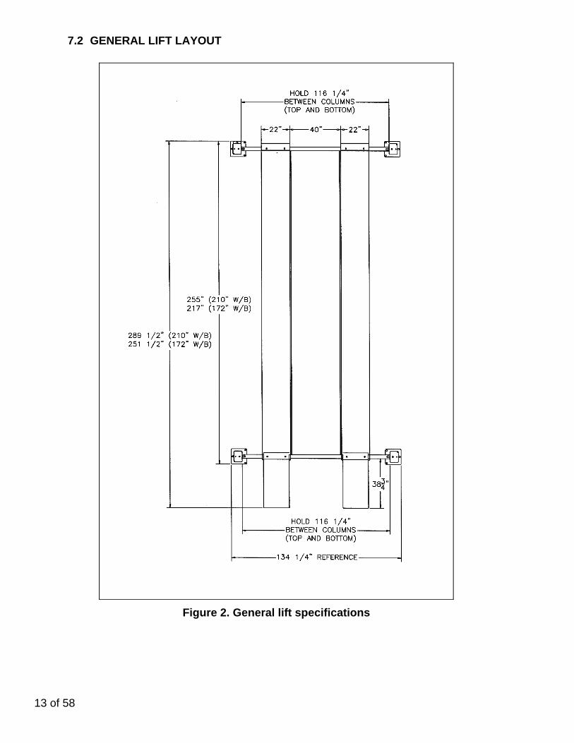
7.2 GENERAL LIFT LAYOUT
Figure 2. General lift specifications

14 of 58
7.3 CHALK LINE LAYOUT
Figure 3. Chalk line layout
WARNING! None of the anchors shall be closer than 4-3/4" to any edge of a concrete slab, expansion joint or crack in the garage floor. Review position oftowers, baseplates and anchors and relocate line "A", "B", "C" & "D" if needed.

15 of 58
1. Refer to Figure 3. Make a chalk line parallel to the doorway at least 275” (172” W/B) or 313” (210” W/B) in from the doorway. This will be the location for the front edge of the front tower baseplates, call this line "A".
2. Determine the center of the doorway and bay. Make a centerline to intersect with line "A". 3. Make two chalk lines spaced 20” to the left and right side of the centerline (40” apart). Call
these lines “B” and “C” respectively. These will be the lines that the inside edge of the runways run along.
4. Make a chalk line spaced 217" (172" W/B) or 255" (210" W/B) from line "A" towards the doorway entering the bay. This will be the location for the rear edge of the rear tower baseplates, call this line "D".
5. Make two chalk lines spaced 67-1/8" to the left and right side of the center line. Call these "E" & "F" respectively. These will be the location of the outside edges of the baseplates.
7.4 IDENTIFICATION OF MAIN LIFT COMPONENTS
Identify and unpack all major lift components (cables, columns, traverse beams, runways) and place them in the general area where they belong (front left, front right, etc).
Figure 4: Component Layout

16 of 58
7.5 ROUTING OF AIRLINES IN CROSSMEMBER
7.5.1 Sheave Removal
1. Prior to assembling the crossmembers to the runways, install the 5/32 pneumatic lines for the safety system.
2. Removing the pulleys may make the following
steps easier. To do so:
3. Remove the 5/16" bolt and lock washer securing the sheave pin.
4. Unhook the two safety spring from the auxiliary
safety.
5. Remove the Sheave Pin, Sheave and spacers.
6. Repeat to other end. Set aside components for later use.
7.5.2 Polytube Routing in Front Crossmember
1. In the accessory box, gather the 5/32 polytube and the 5/32 Tee fittings (6-2433).
2. Cut (3) pieces of 5/32 polytube in the lengths shown below: Line A - 22" Line B - 104" Line C - 8"
Figure 5: Sheave Removal
Figure 6: Front Crossmember Routing
17 of 58
3. Refer to Figure 6. Connect one end of "Line A" to the Tee fitting. On the opposite end of the tee fitting, connect "Line B". Connect "Line C" to the remaining port on the tee fitting.
4. Route this assembly through the crossmember ensuring the ends of line A & B are
routed through the pipe protector at both ends.
5. Connect the ends of the lines A& B to their respective safety cylinder. Note: You can remove excess polytube before connecting to cylinders to eliminate slack.
6. Fish "Line C" though the round access hole on crossmember.
7.5.3 Polytube routing in Rear Crossmember
1. Repeat section 7.5.1 Sheave Removal for the rear crossmember.
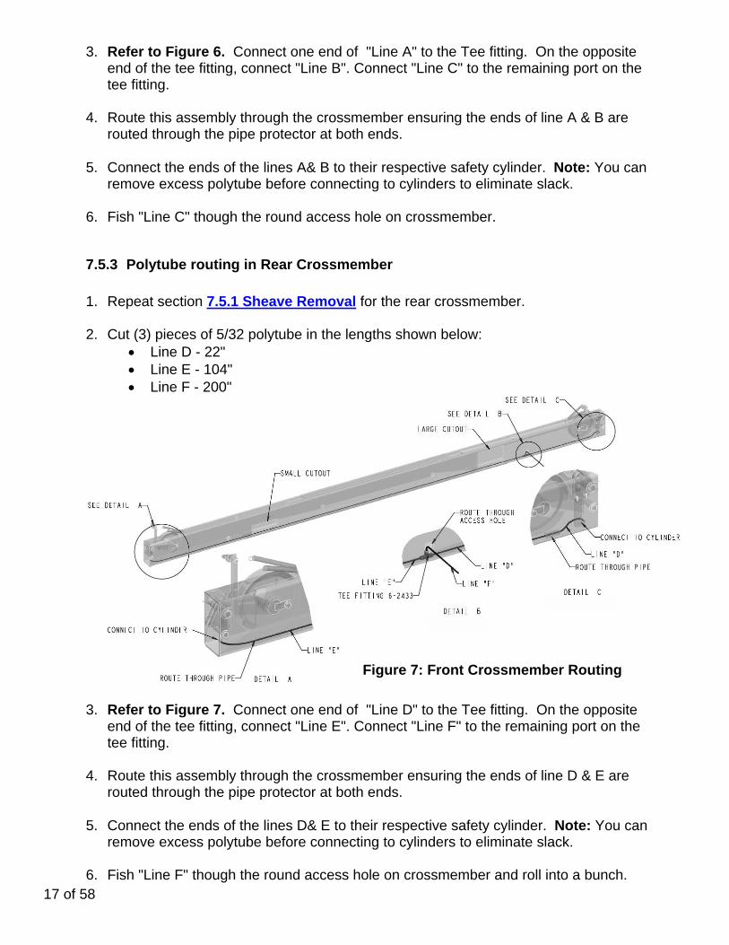
2. Cut (3) pieces of 5/32 polytube in the lengths shown below: Line D - 22" Line E - 104" Line F - 200"
3. Refer to Figure 7. Connect one end of "Line D" to the Tee fitting. On the opposite end of the tee fitting, connect "Line E". Connect "Line F" to the remaining port on the tee fitting.
4. Route this assembly through the crossmember ensuring the ends of line D & E are
routed through the pipe protector at both ends.
5. Connect the ends of the lines D& E to their respective safety cylinder. Note: You can remove excess polytube before connecting to cylinders to eliminate slack.
6. Fish "Line F" though the round access hole on crossmember and roll into a bunch.
Figure 7: Front Crossmember Routing

18 of 58
7.6 RUNWAYS AND CROSSMEMBER INSTALLATION 1. Place the left runway such that the inside surface lies along line "B".
2. Place the right runway such that the inside surface lies along line "A".
3. Support with 4x4 wood blocks under each of end runway.
4. Position both runways so the front edge is 4-1/2" from line "A". See Figure 8.
Figure 8 - Runway Positioning
5. Locate the wheelstops in the accessory box.
6. Position the front crossmember under the mounting tabs of the front runways and align holes.
Ensure that the rectangular openings in the crossmember are facing towards the runways.
7. Align the wheelstops and bolt to runways and crossmember. See Figure 9a.
Figure 9a: Front Crossmember Installation

19 of 58
8. Install the rear crossmember as above, along with the approach ramp hinge. See Figure 9b.
Figure 9b: Rear Crossmember Installation
9. Using a engine hoist (or other lifting devices), pick up the rear of the crossmember/runway
assembly and place two axle stands under crossmember.
10. Repeat for the front. Ensure assembly is sturdy. See Figure 9c. Note:
Adjust axle stands such that it allows enough room to work under the runways.
Ensure runways are leveled before working underneath. Be cautious of not pinching the polytubes perturbed from crossmembers
when assembling to runways.
Figure 9c - crossmember and runways assembly

20 of 58
7.7 CABLE ROUTING 1. Remove the cables from the accessory box and check their part numbers (located on each
stud) to determine routing.
2-1791 FRONT LEFT 172” W/B 2-1677 FRONT LEFT 210” W/B 2-1792 FRONT RIGHT 172” W/B 2-1678 FRONT RIGHT 210” W/B 2-1679 REAR LEFT, 172" & 21" W/B 2-1680 REAR RIGHT, 172" & 21" W/B
2. Remove the (6) deck sheaves (2) deck sheave pins, and (1) deck sheave spacer (2” lg) from
the accessory box. Remove the nylon thrust washers, 5/16" x 3/4 bolts, and 5/16" lock washers from the hardware kit.
3. Remove the red cap from the rear of the cylinder and extend the Hydraulic Cylinder by using
compressed air.
Figure 10: Extension of Cylinder
NOTE: Ensure that the cable flange in installed with the counterbores facing towards the hydraulic cylinder.
Figure 11 - Cable Installation at Flange

21 of 58
4. Cables should be run in the following order. When attaching the cables at the cable flange
this order should be followed in a clockwise direction to prevent cables from becoming tangled.
Rear Left Rear Right Front Left Front Right
5. If required, loosen the cable clamp.
6. Attach the Rear Left cable to the cable flange. Run the cable to the rear of the deck and over
the first pulley as shown in Figure 12. Route the remaining cable through the crossmember, exiting past the safeties. Make sure to place three Nylon washers between the first pulley and the lower pulley box plate.
7. Attach the Rear Right cable to the cylinder at the cable flange next to the previous one. Run
the cable to the rear of the deck and over the second pulley as shown in Figure 12. Route the remaining cable through the crossmember, exiting past the safeties. Make sure to place a Nylon washer between the pulleys.
8. Attach the Front Left cable to the cylinder at the cable flange next to the previous one. Run
the cable to the rear of the deck and over the third pulley as shown in Figure 12 (threaded end comes around 180 degrees into the deck). Make sure to place a Nylon washer between the pulleys.
9. Pull the Front Left cable through the deck (along the right side) making sure to keep the cable
above the deck stiffeners. At the front of the deck, run the cable over the pulley as shown in Figure 12. Route the remaining of the Front Left cable through the crossmember and past the safety lock. Make sure to place three Nylon washers between the first pulley and the lower pulley box plate.
10. Attach the Front Right cable to the cylinder at the cable flange next to the previous one. Run the cable to the rear of the deck and over the fourth pulley as shown in Figure 12 (threaded end comes around 180 degrees into the deck). Make sure to place a Nylon washer between the pulleys.
11. Pull the Front Right cable through the deck (along the left side) making sure to keep the cable
above the deck stiffeners. At the front of the deck, run the cable over the pulley as shown in Figure 12 Route the remaining of the Front Right cable through the crossmember and past the safety lock. Make sure to place a Nylon washer between the pulleys. Use the sheave spacer to fill the remaining gap.
12. Lock the sheave pins with the 5/16”-18UNC x 3/4”LG Hex HD Bolts and lockwashers (found
in the hardware kit). 13. Tighten the hose clamp on the cable flange to secure all the cables. Ensure that the two
retaining nuts are positioned as shown in Error! Reference source not found.11. Using two wrenches, lock the retaining nuts against each other.

22 of 58
Figure 12. Cable Routing (L.S. Deck)
NOTE: While running the cables through the crossmembers, be careful not to run them around the polytube lines. If this occurs, the lines could be pulled out of the air cylinders when the lift powers up, or the polytubes could be subjected to excessive wear against the cables. At this point the decks should be completely fastened to the crossmembers and the threaded portion of each cable should be routed through the crossmembers, past the lock safety. Before proceeding, check that the layout matches that shown in Figure , that the lift is square and that there is a 40” gap between the decks along their entire length. NOTE: The 40" Dimension shown in Figure 2 is critical as it is necessary to allow the jacking beams to roll freely. 14. Reinstall the Sheave, sheave Pin, spacers and hardware that was removed in Section 7.5.1.
Ensure that the cable is in the groove of the sheave.
15. Connect the two springs to the auxiliary safety.
16. Route the cable around the sheave then around the roller on the auxiliary safety. See Figure 14.
23 of 58
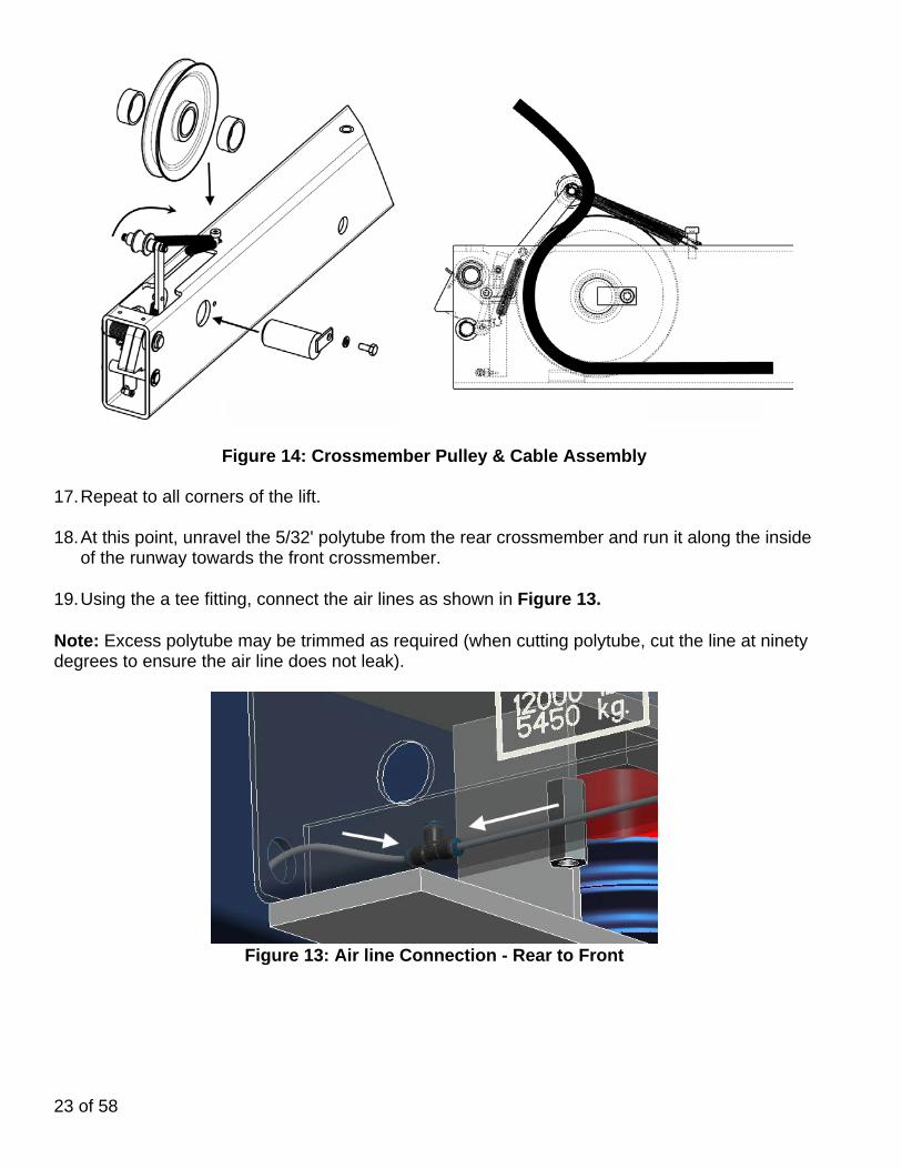
Figure 14: Crossmember Pulley & Cable Assembly 17. Repeat to all corners of the lift. 18. At this point, unravel the 5/32' polytube from the rear crossmember and run it along the inside
of the runway towards the front crossmember.
19. Using the a tee fitting, connect the air lines as shown in Figure 13. Note: Excess polytube may be trimmed as required (when cutting polytube, cut the line at ninety degrees to ensure the air line does not leak).
Figure 13: Air line Connection - Rear to Front
24 of 58
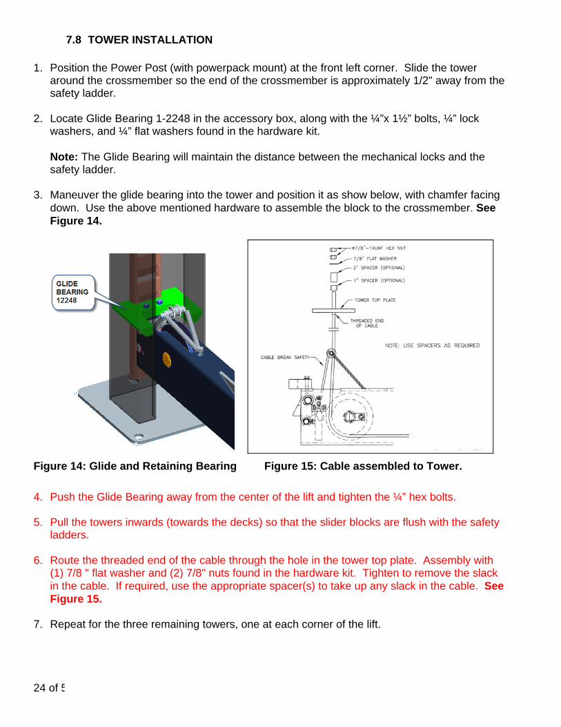
7.8 TOWER INSTALLATION 1. Position the Power Post (with powerpack mount) at the front left corner. Slide the tower
around the crossmember so the end of the crossmember is approximately 1/2" away from the safety ladder.
2. Locate Glide Bearing 1-2248 in the accessory box, along with the ¼”x 1½” bolts, ¼” lock washers, and ¼” flat washers found in the hardware kit. Note: The Glide Bearing will maintain the distance between the mechanical locks and the safety ladder.
3. Maneuver the glide bearing into the tower and position it as show below, with chamfer facing down. Use the above mentioned hardware to assemble the block to the crossmember. See Figure 14.
Figure 14: Glide and Retaining Bearing Figure 15: Cable assembled to Tower.
4. Push the Glide Bearing away from the center of the lift and tighten the ¼” hex bolts.
5. Pull the towers inwards (towards the decks) so that the slider blocks are flush with the safety
ladders.
6. Route the threaded end of the cable through the hole in the tower top plate. Assembly with (1) 7/8 " flat washer and (2) 7/8" nuts found in the hardware kit. Tighten to remove the slack in the cable. If required, use the appropriate spacer(s) to take up any slack in the cable. See Figure 15.
7. Repeat for the three remaining towers, one at each corner of the lift.

25 of 58
7.9 HYDRAULIC INSTALLATION
7.9.1 Power Pack Installation NOTE: When working with hydraulic lines, valves, and fittings, it is important to keep all components clean and free of dirt. 1. Locate the powerpack in the accessory box.
2. Install the power pack to the mounting bracket on the front face of the left front post using the
5/16"-18UNC × 1"LG. hex head bolts, flat washers, lock washers and hex nuts, found in the hardware kit.
Figure16: Power pack details
7.9.2 Hydraulic Hose Installation
1. Locate hydraulic hose assembly 6-1662 and Hose Guard 6-0714 in the accessory box.
Locate elbow fitting 6-0804 in the hardware kit. 2. Connect the end of the flexible hydraulic hose assembly to the flow control at the cylinder.
DO NOT OVER TIGHTEN. See Figure 17a.
3. Feed the hose down the channel inside of the runway toward the front, and then through the hole on the side of the runway. Figure 17b.
4. Run the hose through the hose guard and around the outside of the tower.

26 of 58
5. Connect the remaining end of the hydraulic hose assembly to the powerpack using the 90 deg elbow removed from the hardware kit. DO NOT OVER TIGHTEN. See Figure 17c.
Figure 17a,b,c - Hydraulic Hose Routing
6. Use the frame clips found in the hardware kit to hold the hydraulic line under the deck.
NOTE: Be sure to keep the hydraulic line clear of the cables under the deck.
7.10 AIR INSTALLATIONS 1. Install the air valve and filter assembly (found in
the accessory box) to the mounting bracket on the power post.
2. To do this, pull off the pushbutton and unscrew the plastic nut.
3. Slide the assembly into the mounting bracket and re-fasten the plastic nut so that the assembly is attached to the top hole. Replace the pushbutton by pressing it firmly back onto the air valve and filter assembly.
4. Connect the remaining 5/32" polytube to the fitting on the air valve.
5. Route it through the hose guard down towards the hole in the runway.
6. Under the deck, pull the polytube trough, determines how much is required, and cut.
7. Connect to the remaining port of the tee fitting supplying the safety locks. NOTE: When cutting polytube, be sure to cut the line at 90 degrees. Failure to do so may result in leaks in the air connections.
Figure 18: Air Valve & Filter Installation

27 of 58
8. Hook up an air supply to the inlet of the water trap on the Air Valve and Filter Assembly located on the front left post. Must set air regulator @ 90-100 psi if shop air is higher.
9. Check for air leaks .
10. Check the operation of the air cylinder locks by pressing the pusbutton on the Air Valve and Filter Assembly on the front left post. This should cause the safety locks to be pulled into the crossmembers, releasing the lift from the safety ladders.
NOTE: FOR THOSE UNITS EQUIPPED WITH JACKING BEAMS, THIS IS THE APPROPRIATE TIME TO INSTALL THEM. CONSULT THE JACKING BEAM INSTRUCTION MANUALS FOUND IN EACH JACKING BEAM BOX. NOTE: AN (OPTIONAL) JACK BEAM AIR KIT SHOULD BE USED TO MAKE THE NECESSARY CONNECTIONS BETWEEN THE AIR SUPPLY AND THE JACK BEAMS.
7.11 ELECTRICAL CONNECTIONS A QUALIFIED ELECTRICIAN SHOULD MAKE ALL ELECTRICAL CONNECTIONS.
Refer to Figure 19 for electrical connections. Refer to Page Electrical breaker must be sized by a qualified electrician. Refer to labeling on powerpack for electrical motor ratings.
208-230V, 1Ph, 60Hz. 208-230V, 3Ph, 60Hz.
Figure 19. Electrical diagram

28 of 58
7.12 DECK LEVELING PROCEDURE .
7.12.1 LEVELING SAFETY LADDERS 1. Raise the lift to a comfortable working height.
2. Lower the lift onto the nearest safety.
3. Using a 4ft. level, check the level of the decks 'front to rear' and 'side to side' as shown if
Figure 20.
4. Determine the highest corner of the lift.
5. The other (3) corners will need to be raised to the level of the highest corner. This is accomplished by tightening the safety ladder retaining nuts on top of the tower.
6. Loosen the nut under the tower top plate and adjust the adder as needed.
7. Continuously tighten the top nut (which lift that corner up) until that corner is leveled.
8. Repeat this procedure for all 3 corners while checking the level of the decks.
9. When satisfied, tighten all jam nuts.
Figure 20 - Lift & Deck Leveling

29 of 58
7.12.2 Leveling Lift on Cables
1. Raise the lift off the safety ladder to a comfortable working height such that the lift is suspended on the cables.
2. Using a 4ft level, check the level of the
decks 'front to rear' and 'sided to side' as shown in Figure 20.
3. Determine the highest corner of the lift.
4. The other 3 corners will need to be raised
to the level of the highest corner. This is accomplished by tightening the cable retaining nuts on top of the tower (See Figure 21).
Note: Use optional 1" and 2" spacers in case of uneven floor slope
Note: There should be two nuts retaining the cable to the top plate of the tower. The upper
nut is used as a jam nut to prevent the lower nut from loosening. Both nuts should be installed
after the adjustment is completed.
5. Repeat the preceding steps until the lift is completed level when supported by the cables. Tighten the jam nuts after the adjustment is completed.
6. Make sure that the non-threaded sleeve of each wire rope seats in the cable flange
properly. (See Section Figure 7.7, Figure 11).
7. Raise the lift and check that the ladders engage evenly.
8. Lower the lift onto a mechanical safety position. Raise the lift from this position and ensure the lift rises evenly and level from the resting position.
9. Cycle the lift several times to check proper operation of the cables, safety lock, air
locks, etc.
STOP IMMEDIATELY IF THE LIFT IS NOT OPERATING PROPERLY.
10. Make any necessary adjustments and check again for proper operation.
11. Raise the lift to its full height and check for full operating height of 70". This measurement is taken from the top of the decks to the floor. Lower the lift to the ground when complete
Figure 21: Cable Adjustment

30 of 58
7.13 ANCHOR INSTALLATION 1. Check all layout dimensions on Figure 2 and Figure 3 before continuing with anchor
installation. 2. Refer to Figure 22 while reading through these instructions.
Figure 22. Anchor installation
3. Ensure that the lift is fully supported by the cables and is at a level just above the work
stands. 4. Prior to installing anchors, assemble the nut and washer onto anchors. A minimum of six
threads must be visible below the surface of the nut. 5. Using a 1/2” concrete drill bit and rotary hammer drill, drill through the concrete floor in the
anchor holes positioned on the base of each post. (In case longer anchors are required, supplied anchors can be hammered through concrete).
6. Using a hammer, drive each anchor into floor leaving space for shimming. 7. Use a 4’ level, to level the posts, 'front to back' and 'side to side'. 8. Shim as required and hammer anchors till they make contact with Baseplate. Do not tighten
anchors.
DO NOT use more than 1/2" (13mm) of shims per column. Anchor bolts supplied allow for a maximum of 1/2" of shims. If more than 1/2" is required, DO NOT proceed with installation and contact Snap-On Equipment Technical Support for further details.
9. Check the distance from the top of the anchor to the floor. If this dimension exceeds 2½” due
to floor slope, DO NOT use the supplied anchors. Longer anchor must be used (See Figure 23).
10. Tighten all anchor bolts to a torque of 55 ft. lbs. (75 Nm), continually checking that the
column is level as you proceed. Do not exceed recommended torque spec.

31 of 58
11. Recheck and adjust the level of post(s) and cable(s) if necessary.
Figure 23 - Anchor Depth
NOTE: The 1/2” 4 ½” lg. wedge anchor bolts supplied must have a minimum embedment of 2” into concrete floor. NOTE: If anchors do not tighten to required torque, OR project more than 2-1/2" above the concrete surface due to floor slope, contact a foundation engineer to determine the best course of action. 12. Cycle the lift several times to check
proper operation of the cables, safety lock, air locks, etc.
STOP IMMEDIATELY IF THE LIFT IS NOT OPERATING PROPERLY.
13. Make any necessary adjustments and check again for proper operation.
NOTE: IF THE TOWERS ARE LEANING INTO THE LIFT, THE CROSSMEMBERS CAN BECOME WEDGED INTO THE TOWERS AS THE LIFT RAISES.
NOTE: IN CASES WHERE THE FLOOR IS EXTREMELY OUT OF LEVEL, THE
MECHANICAL SAFETIES MAY NOT ENGAGE ON THE SAME LOCK.
7.13.1 Approach Ramp Installation
1. Install the approach ramps using the ramp pins, 1/8” x 1”LG cotter pins, and approach ramps
provided. The ramps and ramp pins are located in the accessory box, the cotter pins and washers are found in the hardware kit.
2. Ensure the proper operation of the ramps.

32 of 58
7.14 FINAL CHECK OF ASSEMBLED LIFT
1. Final dimension check after anchoring 2. Check for hydraulic leaks. 3. Ensure cables are properly routed and free from obstructions. 4. Check jam nuts on cables are tightened. 5. Check that LOCTITE has been applied to all hardware where
required. 6. Check adjustment of safety release cable to ensure both
sides working properly. 7. Re-check level of towers. 8. Check torque of anchor bolts. 9. Check all fasteners, tighten if necessary. 10. Check shut off at top of stroke to ensure lift shuts off. 11. Check proper operation of arm restraints. 12. Operate lift to full stroke then lower to ground while checking
for proper functionality. 13. Check proper operation of arm restraints. 14. Ensure Customer Care Kit is complete and given to operator. 15. Operation Manual 16. ANSI / ALI Lift It Right Manual 17. ANSI / ALI Safety Tip Card 18. ANSI / ALI ALIS Safety Requirements for Installation 19. ANSI / ALI Quick Reference Guide 20. Train end user on operation of lift.
7.15 OPERATION TEST WITH VEHICLE Lower lift to ground. Drive vehicle on to lift, install wheel chocks. Raise lift to and lower onto 3-4 lock positions during full rise to ensure all locks are working correctly. Double check level of runways, front to rear and side to side while on locks. Re-adjust cables if necessary while vehicle is on. Check lowering speed and smooth decent rate. Lower lift to ground, remove wheel chocks and drive vehicle off lift. If any problems occur during the final checkout or operation of the lift please contact customer service at 1-800-268-7959
33 of 58
OPERATING INSTRUCTIONS
To avoid personal injury and/or property damage, permit only
trained personnel to operate the lift.
After reviewing these instructions, get familiar with lift controls, by running the lift through a few cycles before loading vehicle on lift. Observe and heed SAFETY and WARNING labels on the lift.
7.16 LIFT OPERATION
- Loading: Lift must be fully lowered, and no one in the service bay while the
vehicle is brought in. If the lift is equipped with rolling jacks, jacks must be fully lowered and the rear jack pushed toward center of lift, to provide under-car clearance.
- Stop vehicle before it contacts the front wheel stops. At all times, be sure the rear wheels are forward of the approach ramps/chocks and the approach ramps/chocks will clear the tires when the lift is raised. Driver must exit the vehicle before rising.
- Place triangular wheel chocks on front and rear of one of the rear tires.
- To raise the lift: Push the “RAISE” button on the power unit. Release button at desired height, ensure that all corners have passed a mechanical lock position.
- After raising the lift to the desired height, press and hold the lowering lever on the hydraulic power unit, until lift stops on safety latches. Cross-members should be stopped on safety latches in all 4 towers before any work can start on the raised vehicle. If any of the safety latches is not engaged, try to raise or lower the lift to the next higher or lower safety position, and observe again if all 4 safety latches have engaged. If the problem persists, lower and unload the vehicle, solve the lift safety problem, and only then resume vehicle service.
- Before lowering lift: be sure no one is in the lift area and that all tools, tool trays, etc. have been removed from under the lift and vehicle. If the lift is equipped with rolling jacks, jacks must be fully lowered and the rear jack pushed toward center of lift, to provide under-car clearance.
The runways, approach ramps, and cross-members are designed to rest on the floor when fully lowered. Observe pinch point warning decals.
- To lower lift: if lift has been resting on the safety latches, the lift has to be raised
high enough for all 4 safety latches to clear the openings in the safety ladder. - Actuate the latch release valve on the power unit column to disengage all four
locking latches. Hold actuator until lift is fully lowered.
34 of 58
NOTE: If actuator on air valve is released, the latches will automatically reset to the engaged position.
- Push the lowering handle on the power unit to lower the lift.
- Observe lift and vehicle to be sure lift is level while being lowered. If not, STOP the lift and try to resume lowering as explained above.
- Fully lower lift, remove the triangular wheel chocks and check to be sure area is clear before removing vehicle from lift.
- If lift is not operating properly, do not use until adjustment or repairs have been made by qualified lift service personnel.
- For Rolling Jack operating instructions, see Rolling Jack Installation, Operation and maintenance Instructions in the rolling jack shipping box.
Do not operate lift with pulley covers removed from cross-member ends. Keep hands clear of the cross-member ends when lift is being
raised or lowered.
Do not raise or lower the lift while the jack beams are loaded.
8. RECOMMENDED INSPECTION AND MAINTENANCE
LUBRICATION SPECS Where hydraulic oil is required > ISO 32 10W - non detergent hydraulic oil Where grease is required > multi-purpose lithium grease Where multipurpose lube is required > multi-purpose SAE 30 lubricating oil Where pneumatic oil is required > Snap-On air motor oil IM1PT Where cable lube is required > 2001 MONOLEC® wire rope lubricant or equivalent
If you are not completely familiar with automotive lift maintenance
procedures, STOP. Contact Snap-on Equipment Technical Support for instructions. To avoid personal injury, permit only qualified lift service personnel to perform maintenance on this equipment.
Always raise lift when cleaning floor area with solvents and/or cleaning compounds.
Always replace cable break safety springs when replacing cables. Please refer to the following table for specific inspection and maintenance frequency.

35 of 58
COMPONENT INSPECTION FREQUENCY
DAILY WEEKLY MONTHLY QUARTERLY SEMI-
ANNUALY ANNUALY
Entire Lift and surrounding area
8.13
As shown before, and ALI
Standard
Entire Lift Operation
8.13
Fasteners 8.2 Wire Ropes 8.1.3 8.1.4 8.1.5 Sheaves 8.3.1 8.3.2 Sheave Pins 8.3.3 8.3.2 Safety Dogs 8.4 8.3 Slack Cable Devices
8.5
Latch Plates (Ladders)
8.5
Air Filter, Regulator, Lubricator
8.6
Approach Ramps, Chocks, Wheel Stops
8.11
Anchor Bolts 8.10.2 Edges of Cable Flange Slots
8.1.6
Runways 8.9.1 Columns 8.10.1 Air cylinders, Lines, Fittings
8.6
Hydraulic Power Pack, Hose, Fittings
8.7 8.7
Hydraulic Cylinder
8.8
Jack Beam Rails, Oil Drain Pan
8.9.2
Anti-skid Surfaces
8.11
Rolling Air Jacks
8.12

36 of 58
8.1 WIRE ROPES
Wire ropes are critical to safe and reliable performance of your lift. Cables are expendable items and should be replaced as a set.
8.1.1 WIRE ROPE CONDITIONS GUIDE
Typical good cable
Figure 12
Rust on sheave stack and ropes Corrugated sheave groove
Cable with necking
Broken wires
Excessive wear of wires

37 of 58
8.1.2 WIRE ROPE REPLACEMENT CRITERIA:
If any cable is found to be in need of replacement, the entire cable set, pulleys and safety rollers must be replaced immediately. See 9.1.1, cable conditions guide.
In the following table, "lay" means the distance measured along a line parallel to the axis of the rope in which the strand makes one complete turn about the axis of the rope, or the wires make a complete turn about the axis of the strand.
8.1.3 WIRE ROPE INSPECTION
Inspect wire rope cables for wear or damage. Wipe cables with a rag to detect hard to see small broken or frayed cable strands. See Section 9.1.1 and ANSI/ALI ALOIM standard.
8.1.4 WIRE ROPE LUBRICATION
Lubricate wire ropes with lift in both lowered and raised position, by spraying them with wire rope lubricant (i.e. 2001 MONOLEC®) and wiping the cable down.
The wire rope must be removed from service if one or more of the following criteria are met: 1. More than six randomly distributed broken wires in one rope lay or 6d length. 2. More than three broken wires in one strand in one rope lay or 6d length. 3. Three or more broken wires at rope terminations. 4. One outer wire broken at the point of contact with the core of the rope which has
worked its way out of the rope structure and protrudes or loops out from the rope structure
5. Heavy rusting, corrosion, or pitting. A light surface corrosion on outer wires is normal.
6. Wear or scraping of one-third of the original diameter of outside individual wires
7. Excessive stretch. It is normal for new cable to require adjustment during “break-in”, after which small periodic adjustments may be required. However, if a cable that has been in service for 6 months should suddenly require frequent adjustments or has used all the cable adjustment available, all cables must be replaced immediately.
8. Deformed strands, kinking, crushing, bird caging, or any other damage in distortion of wire rope structure
9. Variations in diameter (necking) or any change from normal appearance
10.
Reductions from nominal diameter of more than 1/32" (for cables 3/8" to 1/2" dia. inclusive)
11.
End attachments cracked, deformed or worn

38 of 58
8.1.5 WIRE ROPE ADJUSTMENT
Adjust cables if lifting is uneven or lift is not level (See chapter 6.10.3). Never make adjustments with weight on lift. If running out of adjustment threads, cables need to be replaced. Do not add washers or other spacers to re-use previously used adjustment threads. Wire rope tension adjustment should be performed when installing the lift and every three months.
8.1.6 INSPECT CABLE FLANGE Make sure the edges of the counter-bores in the cable flange are not damaged or worn, indicating that cable sleeves may not be properly seated at all times.
8.2 FASTENERS Check all the attaching bolts and nuts for tightness. Note: Air cylinder bolts and nuts should allow movement of the cylinder.
8.3 SHEAVES AND PINS
Sheaves and pins are expendable items. Sheaves and pins should be replaced when worn. Use of sheaves and pins with excessive wear will lead to reduced service life of the cables.
Bushings inside sheaves work best in “dry” condition. Applying oil will diminish their performance and greases will degrade performance even further. DO NOT GREASE SHEAVE BUSHINGS OR SHAFTS.
8.3.1 VISUAL INSPECTION OF SHEAVES
Check sheaves and replace if cracks or other damage are found. Visually inspect alignment of sheaves. Misalignment of sheaves indicates excessive wear.
Remove, inspect, and, if needed replace sheave and pin.
8.3.2 MEASURE SHEAVE WEAR
Inspect sheaves in cross-members with lift in lowered position and resting on safety latches
Place safety stands under front and rear cross-members. Stop lift on mechanical safety locks. One person should hold the lowering handle on power unit down while another person pulls on cables in each column to create slack in cables.
Check for ease of rotation. If sheaves do not turn freely, the sheave and sheave pin should be removed, inspected, fixed or replaced.

39 of 58
hanism may not be as n.
Fully raise the lift, to inspect sheaves in runways. Hold lowering handle down to lower lift onto safety latches
Pull on cables in runway to create slack in cables. Check all sheaves for excessive wobble, or movement. Grasp rim of sheave and attempt
to wobble (tilt) side to side. If sheaves wobble (tilt) more than 3/16” (1.6 mm) side to side, or move in and out more than 1/32 (0.8 mm), the sheave and sheave pin (shaft) should be replaced. Replace immediately if needed.
8.3.3 SHEAVE PINS
Sheave pins are held in place by a Hex Head Bolt, washer and lock washer. Check for loose sheave pins, loose or missing fasteners to hold sheave pins in place. Remediate situation immediately.
8.4 MECHANICAL SAFETY LATCHES (DOGS)
Watch and listen to safety latch operation during lift operation, to ensure that latches move
as required, have not lost spring preload, and line up with slots in latch plates (safety ladders) in columns. Watch for broken traction springs on safety latches.
Check and adjust safety ladders if lift is not level on safety, or if safeties do not engage properly. Stop using the lift if any malfunction or damage is observed.
8.5 CABLE BREAK SAFETY MECHANISM
With lift not loaded, all four cable break levers should produce deflection of the lift cables. Inspect slack cable device as follows: Check for missing or damaged parts. Watch for broken springs. Check if the spring is
properly seated in the support tube and in the holder on the cable break safety lever. Watch cable tracking properly
on cable break safety roller. Check if the safety roller and bolt are properly attached to the cable break safety lever. Verify that the cable break safety lever is centered within the cross-member, and that it lines
up with the openings in the safety ladder. Verify using hand force or a light lever that the cable break safety lever pivots on the shaft. Lubricate with light lubricant if required.
8.6 AIR CYLINDERS, AIR LINES, VALVE AND FITTINGS
Check filter/regulator/lubricator in supply line to lift. (customer supplied, typically at compressor). Drain water trap filter bowl and adjust oil feed according to manufacturer’s instructions.
Drain water bowl on lift supplied water separator. Press valve at the bottom of the bowl to clear.
Check operation of air release valve for air leaks. Check air cylinders for visible damage. Check air lines for leaks, wear or kinks.
8.7 HYDRAULIC POWER PACK AND HOSE
Check all air and hydraulic hoses, fittings and cylinders for leaks.

40 of 58
Check level of oil in power pack reservoir when lift is in the lowered position. Add if required.
Check fluid level of lift power unit and refill if needed. If refill was needed, inspect all fittings, hoses and seals. Tighten, repair or replace as required.
Change hydraulic fluid every 2 years.
8.8 HYDRAULIC CYLINDER
Inspect the hydraulic cylinder mounting to the runway. Inspect cylinder and hydraulic hose for leaks. Repair or replace as required.
Check and tighten the hydraulic cylinder rod nuts holding the cable flange. Inspect bolts holding anti-rotation bar onto cable flange and tighten if required. (If
applicable) Inspect sliders on anti-rotation bar for excessive wear or damage. Replace if required. (If
applicable)
Failure to do so will lead to reduced service life, which could result in property damage and/or personal injury.
8.9 RUNWAYS
8.9.1 CHECK RUNWAYS
Check level of runways on the floor, on the locks and on the cables: Refer to Section 6.10. Adjust as required.
Check runways for damage or abnormal deformation. If such conditions exist, contact Snap-on Equipment Technical Support.
8.9.2 INSPECT JACK BEAM TRACKS
Inspect rolling jack / oil drain pan tracks for cleanliness, corrosion, excessive wear or damage. Clean dirty tracks. Worn or damaged tracks should be repaired immediately.
8.10 COLUMNS
8.10.1 CHECK COLUMNS
Check columns for corrosion, giving special attention to the area at the base of the column.
Check severely corroded areas by pecking with an awl or welder’s chipping hammer. If column is corroded through at any point, it must be replaced immediately. If not corroded through, remove old paint and rust scale, then coat with a high quality corrosion resistant paint. Clean and lubricate glide blocks.
8.10.2 CHECK COLUMN ANCHORS
Check column anchor bolts for tightness (if loose, re-torque to 55 ft-lb). If anchors do not tighten to required torque, or continue to loosen, contact Snap-on Equipment Technical Support.
Verify proper embedment of anchors after tightening.

41 of 58
NOTE: The 1/2” 4 ½” lg. wedge anchor bolts supplied must have a minimum embedment of 2” into the concrete floor. NOTE: If anchors do not tighten to required torque, OR project more than 2-1/2” above the concrete surface due to floor slope, contact a foundation engineer to determine the best course of action.
8.11 APPROACH RAMPS, CHOCKS, FRONT WHEEL STOPS
Inspect for excessive wear or damage. Repair or replace if required.
Inspect hinge pins. Replace if excessively worn. Lubricate if in good condition
8.12 ROLLING AIR JACKS
Lubricate roller bearings and roller guide springs. Dismantle and clean lift arms. Clean and lubricate rollers/sliders and hinge points. Clean and lubricate safety mechanism. Change hydraulic oil every two years
8.13 ENTIRE LIFT
Wire ropes, columns, runways and other lift parts should be kept free of corrosive agents, solvents, and road salts. If such agents are spilled or splashed on any lift component, immediately rinse thoroughly with water and wipe down with a clean rag. Lubricate again wire rope as shown at 8.2.4.
Check general operation of lift. Observe any structural noise, imbalance, binding, or other
malfunctions.
Failure to keep the lift free of corrosive agents and solvents will lead to reduced component service life, cable failure, etc., which could result in property damage and/or personal injury.

42 of 58
9. MAINTENANCE SCHEDULE
Maintenance and Training Performed Date By Notes

43 of 58
10. LOCK OUT AND TAG OUT INSTRUCTIONS IMPORTANT: This machine does not have integral devices that will isolate the electrical, pneumatic, stored and hydrualic energy source. Appropriate isolation or blocking devices must be used that have the provisions to be switched in the off position and locked in that position.
ALL MAINTANANCE AND SERVICE MUST BE PERFORMED BY A QUALIFIED PERSON.
ALL MAINTANANCE AND SERVICE MUST BE PERFORMED WITH THE LIFT UNLOADED. IT IS THE SHOP OWNERS RESPONSIBILITY TO ENSURE ENERGY ISOLATING DEVICES ARE:
Accessible Conveniently located to facilitate the application of lockout devices during service
and maintenance Located outside any hazardous area. At a convenient manipulating height (i.e. not overhead, on ladders or under
machinery) Adequately labeled or marked. Identification shall include machine ID, energy type
and magnitude. Capable of being locked or otherwise secured in an effective isolating position.
Effective hazardous energy control procedures will protect employees during machine and equipment servicing and maintenance where the unexpected energization, start up or release of stored energy could occur and cause injury, as well as while working on or near exposed de-energized electrical conductors and parts of electrical equipment. Hazards being guard against include being caught in, being crushed by, being struck by, being thrown from, or contacting live electrical circuits/parts. In preparation for lockout, an initial survey must be made to locate and identify all energy isolating devices to be certain which switch, valve, or other energy isolating devices apply to the machine / equipment to be locked out. More than one energy source (electrical, hydraulic, pneumatic, or others) may be involved.
10.1 SHUT DOWN PROCEDURE:
Notify all affected employees that a lockout or tagout system is going to be utilized and
the reason for. The authorized employee shall know the type and magnitude of energy that the lift utilizes and shall understand the associated hazards.
ELECTRICAL: Located at the user control panel, press the “E-STOP” button (if available) to disconnect the raise and lower functions.
44 of 58
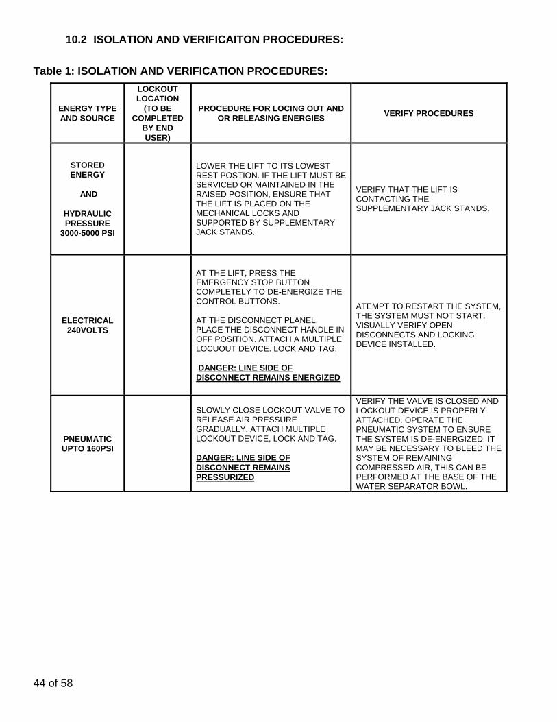
10.2 ISOLATION AND VERIFICAITON PROCEDURES:
Table 1: ISOLATION AND VERIFICATION PROCEDURES:
ENERGY TYPE AND SOURCE
LOCKOUT LOCATION
(TO BE COMPLETED
BY END USER)
PROCEDURE FOR LOCING OUT AND OR RELEASING ENERGIES
VERIFY PROCEDURES
STORED ENERGY
AND
HYDRAULIC PRESSURE
3000-5000 PSI
LOWER THE LIFT TO ITS LOWEST REST POSTION. IF THE LIFT MUST BE SERVICED OR MAINTAINED IN THE RAISED POSITION, ENSURE THAT THE LIFT IS PLACED ON THE MECHANICAL LOCKS AND SUPPORTED BY SUPPLEMENTARY JACK STANDS.
VERIFY THAT THE LIFT IS CONTACTING THE SUPPLEMENTARY JACK STANDS.
ELECTRICAL 240VOLTS
AT THE LIFT, PRESS THE EMERGENCY STOP BUTTON COMPLETELY TO DE-ENERGIZE THE CONTROL BUTTONS. AT THE DISCONNECT PLANEL, PLACE THE DISCONNECT HANDLE IN OFF POSITION. ATTACH A MULTIPLE LOCUOUT DEVICE. LOCK AND TAG. DANGER: LINE SIDE OF DISCONNECT REMAINS ENERGIZED
ATEMPT TO RESTART THE SYSTEM, THE SYSTEM MUST NOT START. VISUALLY VERIFY OPEN DISCONNECTS AND LOCKING DEVICE INSTALLED.
PNEUMATIC UPTO 160PSI
SLOWLY CLOSE LOCKOUT VALVE TO RELEASE AIR PRESSURE GRADUALLY. ATTACH MULTIPLE LOCKOUT DEVICE, LOCK AND TAG. DANGER: LINE SIDE OF DISCONNECT REMAINS PRESSURIZED
VERIFY THE VALVE IS CLOSED AND LOCKOUT DEVICE IS PROPERLY ATTACHED. OPERATE THE PNEUMATIC SYSTEM TO ENSURE THE SYSTEM IS DE-ENERGIZED. IT MAY BE NECESSARY TO BLEED THE SYSTEM OF REMAINING COMPRESSED AIR, THIS CAN BE PERFORMED AT THE BASE OF THE WATER SEPARATOR BOWL.

45 of 58
10.3 RETURNING TO SERVICE:
Check the lift and the immediate area around the lift to ensure that nonessential items,, tools and parts are removed and that the lift components are operationally intact.
Check the work area to ensure that all employees have been safely positioned or removed from the work area.
Notify all employees that the lockout/tagout is going to be removed and the lift is going to restarted.
Remove the lockout/tagouts in the reverse order as the installation.
Verify the proper operation of the equipment.
Notify affected employees that the maintenance/service is completed and the machine is ready for operation.
10.4 EMERGENCY OPERATION:
If the lift becomes inoperative in the raised position, it is best to wait until the electrical power is restored before lowering the vehicle. However, if it’s critical to safety that the lift be lowered, the following steps should be taken. NOTE: Safely performing this process requires 3 people. All personnel should stay clear of the path of the lift. All tools and other non-secured items should be removed from the surface of the runways.
1) Survey the area surrounding the lift; remove any items and personnel from area before proceeding with this procedure.
2) Perform the appropriate lockout/tag out procedure on the electrical energy. 3) Add additional chocks to the vehicle to secure it from movement in the forward and rear
direction. 4) Use a second person standing at a safe distance away from the lift to keep watch on the
area, lift, vehicle and other personnel throughout the process. This person should signal the person performing the procedure to stop if necessary.
5) Use a caution tape or similar to barrier the area around the lift to avoid personnel from accidently entering the area while this process is being performed.
6) Do not proceed with this procedure if you are unfamiliar with the lift or its function.
IF THE MECHANICAL LOCKS ARE NOT ENGAGED:
1) If there is air pressure in the pneumatic system; have another person press and hold the mechanical safety release button to disengage the mechanical locks. Confirm that all mechanical locks have been disengaged and will allow the lift to lower. If there is no air pressure in the pneumatic system; use a portable compressor to provide a temporary air supply to the system.
2) Press and hold the safety release button.
WARNING: DO NOT LOOSEN OR REMOVE HYDRAULIC CONNECTIONS OR FITTINGS UNDER PRESSURE. SERIOUS INJURY OR DEATH COULD OCCUR.

46 of 58
3) Verbally indicate to all those involved that the lift will now be lowered. 4) Slowly push the lowering lever on the powerpack to lower the lift. 5) Keep a close eye on the movement of the lift and the position of the vehicle; release
the lowering lever if any abnormal movement is detected. 6) Once the lift is fully lowered, disconnect the temporary air supply. 7) Once power is restored follow the lockout/tag out procedure to return the lift back
into service.
IF THE MECHANICAL LOCKS ARE ENGAGED: Various methods can be used to raise the lift in order to get sufficient clearance to disengage the mechanical locks. The safest method would employ temporary electrical power to the lift using a portable power generator. Any electrical connections should be done by a licensed electrician; lock out/tag out procedures should also be employed at this time. This process should only be performed by a trained professional. Contact customer service or a local service professional for further assistance.
47 of 58
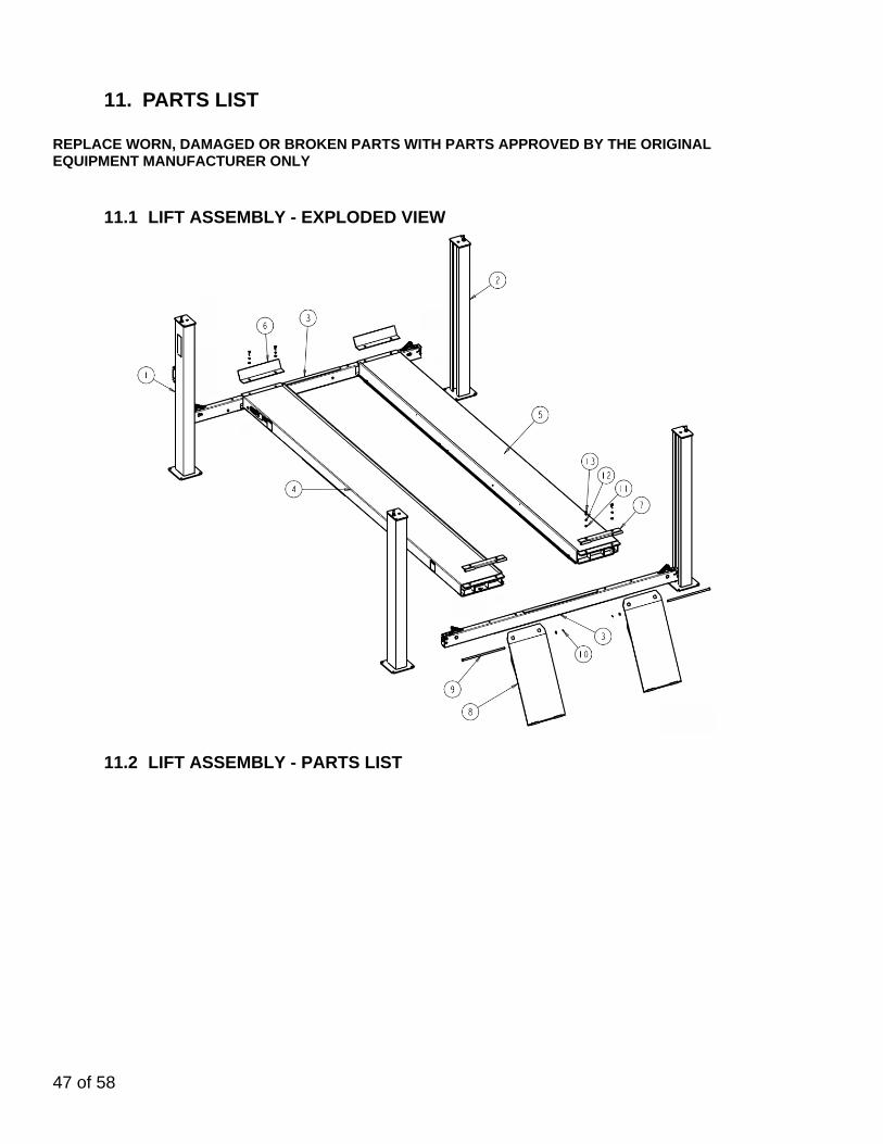
11. PARTS LIST REPLACE WORN, DAMAGED OR BROKEN PARTS WITH PARTS APPROVED BY THE ORIGINAL EQUIPMENT MANUFACTURER ONLY
11.1 LIFT ASSEMBLY - EXPLODED VIEW
11.2 LIFT ASSEMBLY - PARTS LIST
48 of 58
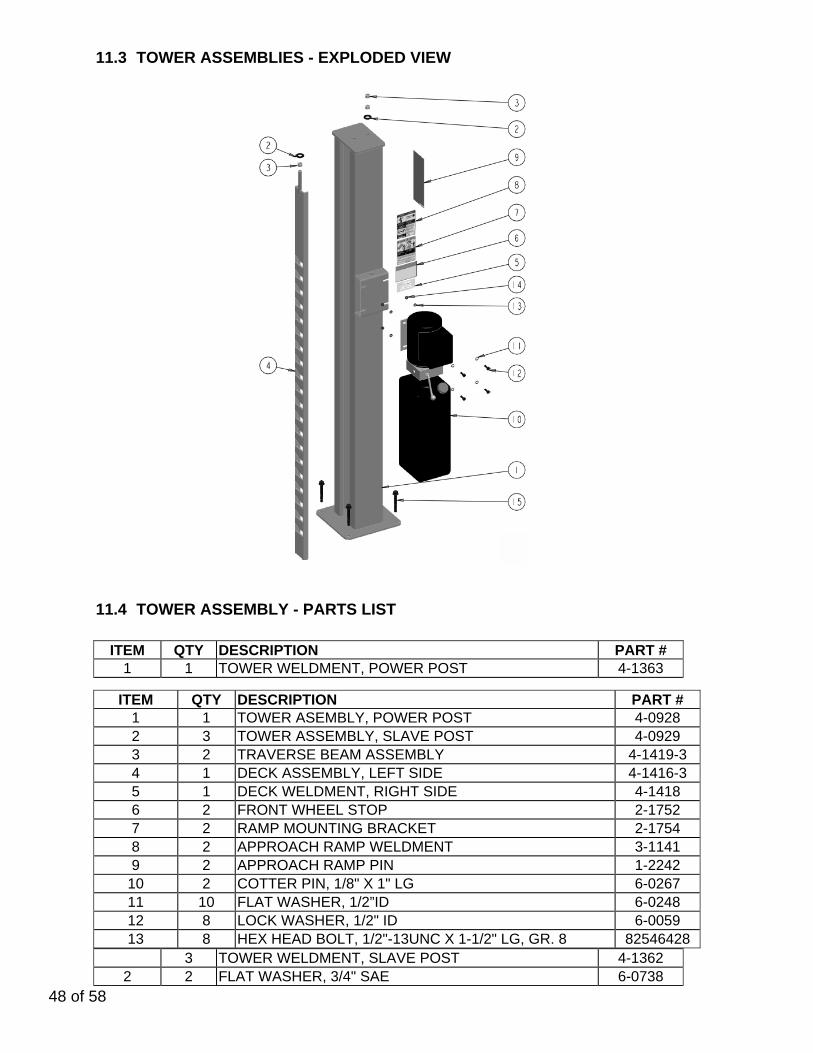
11.3 TOWER ASSEMBLIES - EXPLODED VIEW
11.4 TOWER ASSEMBLY - PARTS LIST
ITEM QTY DESCRIPTION PART # 1 1 TOWER WELDMENT, POWER POST 4-1363
3 TOWER WELDMENT, SLAVE POST 4-1362 2 2 FLAT WASHER, 3/4" SAE 6-0738
ITEM QTY DESCRIPTION PART # 1 1 TOWER ASEMBLY, POWER POST 4-0928 2 3 TOWER ASSEMBLY, SLAVE POST 4-0929 3 2 TRAVERSE BEAM ASSEMBLY 4-1419-3 4 1 DECK ASSEMBLY, LEFT SIDE 4-1416-3 5 1 DECK WELDMENT, RIGHT SIDE 4-1418 6 2 FRONT WHEEL STOP 2-1752 7 2 RAMP MOUNTING BRACKET 2-1754 8 2 APPROACH RAMP WELDMENT 3-1141 9 2 APPROACH RAMP PIN 1-2242
10 2 COTTER PIN, 1/8" X 1" LG 6-0267 11 10 FLAT WASHER, 1/2”ID 6-0248 12 8 LOCK WASHER, 1/2" ID 6-0059 13 8 HEX HEAD BOLT, 1/2"-13UNC X 1-1/2" LG, GR. 8 82546428

49 of 58
3 3 HEX NUT 5/8", GRADE 8 6-0673 4 1 SAFETY LADDER WELDMENT 3-0832 5 1 SAFETY DECAL 6-1637 6 1 WARNING DECAL, DECK LEVELING 6-4086 7 1 ALI DECAL, CAUTION WL200C 8 1 ALI DECAL, NOTICE WL200S 9 1 ALI DECAL, WARNING WL200W
10 1 POWERPACK, 220V / 1PH / 60HZ 6-1936 11 4 FLAT WASHER, 5/16" 6-0295 12 4 HEX HEAD BOLT, 5/6"-18UNC X 1" LG 6-0293 13 4 LOCK WASHER, 5/16" 6-0674 14 4 HEX NUT, 5/16"-18UNC 6-0294 15 16 WEDGE ANCHOR, 1/2" X 4-1/2" LG 6-0140
50 of 58
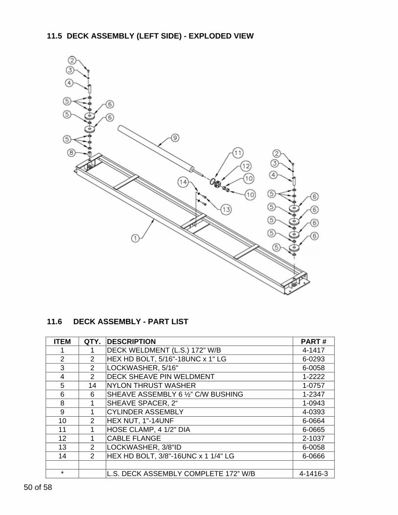
11.5 DECK ASSEMBLY (LEFT SIDE) - EXPLODED VIEW
11.6 DECK ASSEMBLY - PART LIST
ITEM QTY. DESCRIPTION PART #
1 1 DECK WELDMENT (L.S.) 172” W/B 4-1417 2 2 HEX HD BOLT, 5/16"-18UNC x 1" LG 6-0293 3 2 LOCKWASHER, 5/16" 6-0058 4 2 DECK SHEAVE PIN WELDMENT 1-2222 5 14 NYLON THRUST WASHER 1-0757 6 6 SHEAVE ASSEMBLY 6 ½” C/W BUSHING 1-2347 8 1 SHEAVE SPACER, 2“ 1-0943 9 1 CYLINDER ASSEMBLY 4-0393
10 2 HEX NUT, 1"-14UNF 6-0664 11 1 HOSE CLAMP, 4 1/2" DIA 6-0665 12 1 CABLE FLANGE 2-1037 13 2 LOCKWASHER, 3/8"ID 6-0058 14 2 HEX HD BOLT, 3/8"-16UNC x 1 1/4" LG 6-0666
* L.S. DECK ASSEMBLY COMPLETE 172” W/B 4-1416-3

51 of 58
11.7 CROSSMEMBER ASSEMBLIES - EXPLODED VIEW

52 of 58
11.8 CROSSMEMBER ASSEMBLY - PARTS LIST
ITEM QTY. DESCRIPTION PART # 1 2 REAR CROSSMEMBER 4-0869 3 8 SHEAVE SPACER 1-3758 4 4 SHEAVE ASSEMBLY C/W BUSHING 1-2347 5 4 CROSSMEMBER SHEAVE PIN WELDMENT 1-3756 6 4 LOCKWASHER, 5/16" 6-0674 7 4 HEX HD BOLT, 5/16"-18UNC x ¾” LG 6-0423 8 4 LOCK SAFETY PIN 1-2130 9 8 CIRCLIP, 3/4” 6-2422
10 8 CIRCLIP, 5/8” 6-2442 11 4 CABLE BREAK PIN 1-4075 12 8 THREADED INSERT, ½”-NC 6-2432 13 4 SHOULDER BOLT, 3/8” X ½” 6-1792 14 4 GLIDE BEARING 1-2248 15 8 FLATWASHER, ¼” 6-0060 16 8 HEX HD BOLT, ¼”-NC X 1 ½” 6-0205 17 4 TENSION SPRING 1-0768 18 4 CABLE ROLLER 1-0766 19 4 CABLE BREAK LEVER 1-2475 20 4 CABLE BREAK LOCK 1-4077 21 12 THRUST WASHER 6-0502 22 4 SAFETY LOCK 1-4078 23 4 SAFETY LINKAGE 1-2249 24 8 CIRCLIP, 3/16” 6-2431 26 4 MACHINE SCREW, #10-32 X ½” 6-2446 27 4 ROD CLEVIS & PIN 6-2435 28 8 HEX NUT, ¼” 6-0032 29 8 LOCKWASHER, ¼” 6-0056 30 4 CYLINDER MOUNTING BRACKET 1-2315 31 4 AIR CYLINDER 6-2434 32 4 ROUND HD SCREW, ¼” X 5/8” 6-0335 33 4 TORSION SPRING 1-2316 34 4 SAFETY SPRING 1-1115 35 8 SELF THREADING SCREW, #10 X 3/8” 6-0169 36 8 SPACER 1-2907

53 of 58
11.9 CABLE ROUTING

54 of 58
11.10 CABLE ROUTING - PARTS LIST
QTY DESCRIPTION PART # 1 CABLE ASSY. - FRONT LEFT 172” W/B 2-1791 CABLE ASSY. - FRONT LEFT 210” W/B 2-1677
1 CABLE ASSY. - FRONT RIGHT 172” W/B 2-1792 CABLE ASSY. - FRONT RIGHT 210” W/B 2-1678
1 CABLE ASSY. - REAR LEFT 2-1679 1 CABLE ASSY. - REAR RIGHT 2-1680 8 HEX NUT, 7/8”-14UNF GR5 6-0724 4 CABLE SPACER, 2”LG 1-0800 4 FLAT WASHER, 7/8”ID 6-0725 4 CABLE SPACER, 1”LG 1-0801
55 of 58
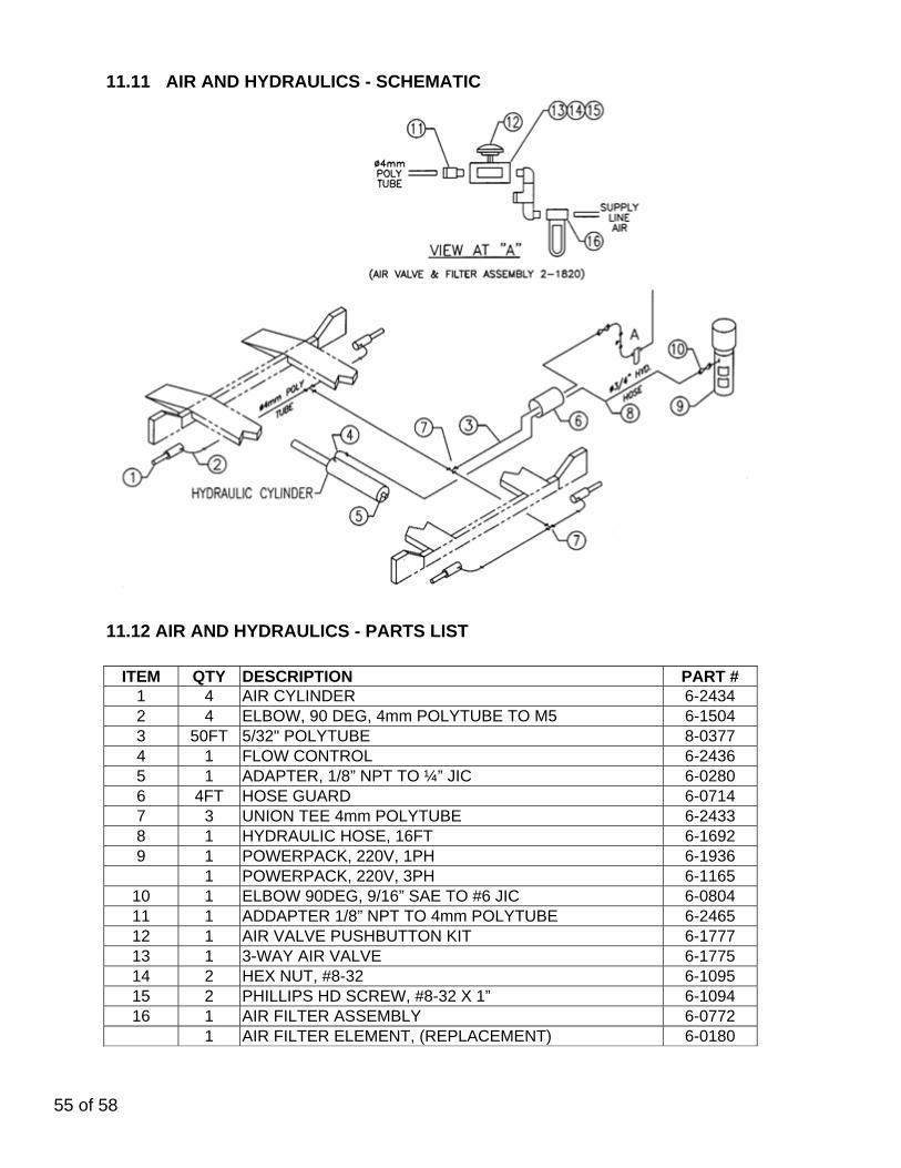
11.11 AIR AND HYDRAULICS - SCHEMATIC
11.12 AIR AND HYDRAULICS - PARTS LIST
ITEM QTY DESCRIPTION PART # 1 4 AIR CYLINDER 6-2434 2 4 ELBOW, 90 DEG, 4mm POLYTUBE TO M5 6-1504 3 50FT 5/32" POLYTUBE 8-0377 4 1 FLOW CONTROL 6-2436 5 1 ADAPTER, 1/8” NPT TO ¼” JIC 6-0280 6 4FT HOSE GUARD 6-0714 7 3 UNION TEE 4mm POLYTUBE 6-2433 8 1 HYDRAULIC HOSE, 16FT 6-1692 9 1 POWERPACK, 220V, 1PH 6-1936 1 POWERPACK, 220V, 3PH 6-1165
10 1 ELBOW 90DEG, 9/16” SAE TO #6 JIC 6-0804 11 1 ADDAPTER 1/8” NPT TO 4mm POLYTUBE 6-2465 12 1 AIR VALVE PUSHBUTTON KIT 6-1777 13 1 3-WAY AIR VALVE 6-1775 14 2 HEX NUT, #8-32 6-1095 15 2 PHILLIPS HD SCREW, #8-32 X 1” 6-1094 16 1 AIR FILTER ASSEMBLY 6-0772
1 AIR FILTER ELEMENT, (REPLACEMENT) 6-0180

56 of 58
11.12 POWER PACK

57 of 58
11.13 POWERPACK - PARTS LIST #6-1936 (AB-1400) & #63125 208-230V/1PH/60Hz #6-1165 (AD-1044) 208-230V/3PH/60Hz
ITEM QTY. DESCRIPTION PART # 1 1 VALVE CARTRIDGE CHECK 6-1087 2 1 LABEL INSTALLATION AUTOHOIST 6-2136 4 1 BREATHER CAP & BLADDER 6-1376 6 1 MOTOR AC 208-230V. 2HP/1PH/60Hz, BLK 6-2139 1 MOTOR AC 208-230V. 2HP/3PH/60Hz, BLK 6-1079 7 1 LABEL WARNING AUTOHOIST 6-2149 9 1 SPRING 0.480” x 0.063” x 0.42” COMP 6-2151 10 1 RETURN HOSE 3/8” OD x 21.5” 6-2152 11 1 COMPRESSION TUBE NUT 6-2153 12 1 COMPRESSION TUBE SLEEVE 6-2154 13 1 ENDHEAD UNIVERSAL AUTOHOIST 6-2155 14 1 PUMPASSY 3.1 CC/REV. SHORT SPLINE 6-1688 15 1 RELIEF ASSEMBLY FIXED 170 BAR 6-1317 16 1 VALVE CARTRIDGE RELEASE MANUAL 6-0880 17 1 WIRING ASSEMBLY AC 1PH FENNER 6-2156 1 WIRING ASSEMBLY AC 3PH FENNER 6-0918 18 2 BOLT 5/16”-24 x 3.00” TORX G8 6-1090 19 1 COUPLING SAE 9T-20/40 1.260” 6-0774 20 1 PLUMBING PLUG 9/16” SAE 6-2157 21 1 SEAL SHAFT 0.500” x 1.00” x 0.25” 6-2158 22 1 WASHER 0.338” x 0.625” x 0.060” STEEL 6-2159 24 1 PLUMBING PLUG 3/8” NPT 6-2161 25 1 PLUMBING MAGNET 6-2162 27 2 SCREW TAPTITE M6 x 1.0 12MM TORX 6-2164 28 1 COVER ASSY SUCTION 6-2165 29 1 PLUMBING CLAMP HOSE ADJ. INLET 6-2166 30 1 BOLT 5/16”-18 x 1.00” SHCS 6-1392 31 1 NUT ¾”-16 x 1” HEX x 0.250” STEEL 6-2167 32 1 WASHER ¾” INT. TOOTH LOCK 6-2168 33 1 BRACKET – HANDLE ASSY REL BLACK 6-0776 34 4 BOLT M6 x 1.0 35MM SOC HD 6-2169 35 4 WASHER ¼” LOCK HI-COLLAR 6-2170 37 4 BOLT #12-24 x 0.50’ HEX WSHRHD 6-1091 38 1 PLUMBING ASSY INLET 17.24 (3) 6-0786 39 1 RELIEF VALVE CAP ASSEMBLY 6-1089 40 1 TANK PLASTIC 6.7 OS 22.50” BLK 6-1399 41 1 CABLE TIE 8” LONG WHITE 6-1846 42 1 O-RING 2-348 BUNA 6-0875

58 of 58
12. AVAILABLE ACCESSORIES Hydraulic Jack Beams
Premium Air / Hydraulic Jack
Beam
Standard Air / Hydraulic Jack Beam
6000 lb, 7000 lb 6000 lb, 7000 lb Other Accessories
Drive-On Ramp Extension for Low Profile
Vehicle (set of 2)
Air Outlet Kit (Factory Installed)
Sliding Waste Collection Oil Tank 26 gal.
Drive-thru Kit (Quad Rack)
Front Turning Radius Plates
(set of 2)
Alignment Pan Cover, 4-Post
Stainless Steel Turnplates
Rollback Kit (for Stainless Steel
Turnplates)
Air / Electric Service Station for 2-Post & 4-
Post
Rear Slip Plate Refurb Kit -
Staniless Steel Base ( 24"
Decks Only - set of 2 )
NO PICTURE AVAILABLE
Roll Forward Kit (4-Post)
Tsunami Kit (in-line compressed
air dryer)
Accessories may not be available for all models. Contact supplier for availability and part numbers.