installation construction for herkules er
TRANSCRIPT
www.fugenprofile.de * Tel: 0821/4559690 * [email protected]
Installation construction for Herkules ER
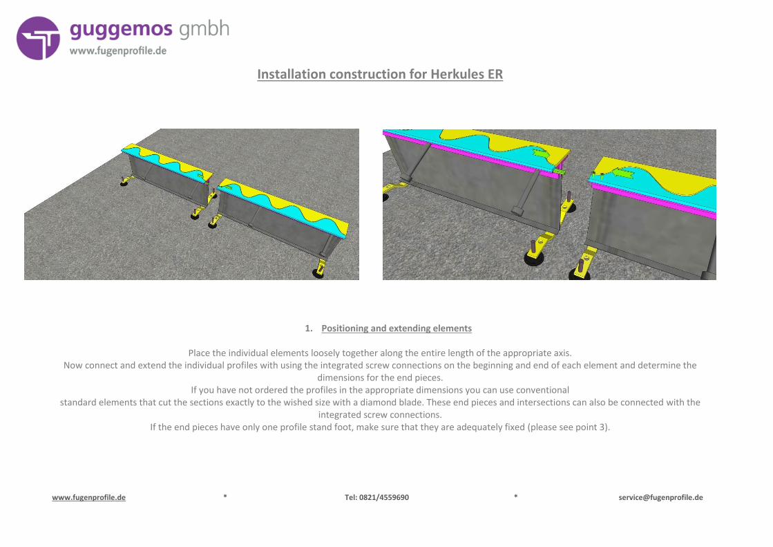
1. Positioning and extending elements
Place the individual elements loosely together along the entire length of the appropriate axis. Now connect and extend the individual profiles with using the integrated screw connections on the beginning and end of each element and determine the
dimensions for the end pieces. If you have not ordered the profiles in the appropriate dimensions you can use conventional
standard elements that cut the sections exactly to the wished size with a diamond blade. These end pieces and intersections can also be connected with the integrated screw connections.
If the end pieces have only one profile stand foot, make sure that they are adequately fixed (please see point 3).
www.fugenprofile.de * Tel: 0821/4559690 * [email protected]
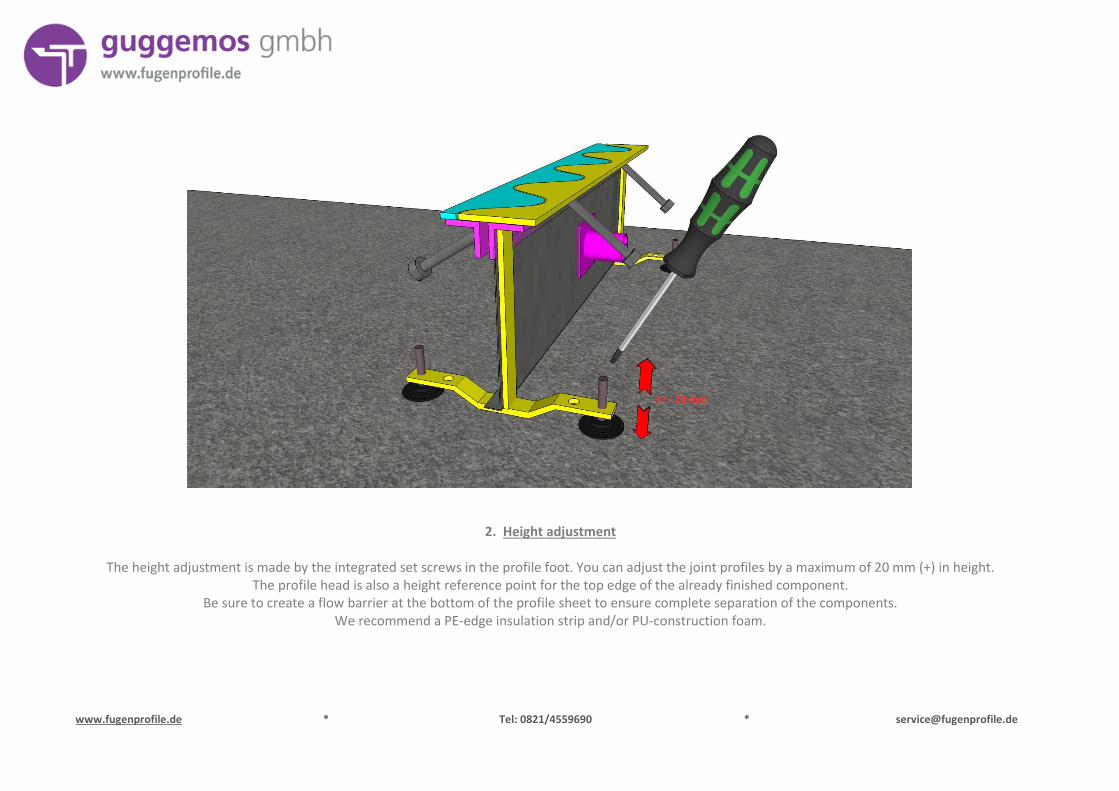
2. Height adjustment
The height adjustment is made by the integrated set screws in the profile foot. You can adjust the joint profiles by a maximum of 20 mm (+) in height. The profile head is also a height reference point for the top edge of the already finished component.
Be sure to create a flow barrier at the bottom of the profile sheet to ensure complete separation of the components. We recommend a PE-edge insulation strip and/or PU-construction foam.
www.fugenprofile.de * Tel: 0821/4559690 * [email protected]
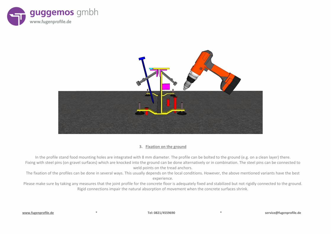
3. Fixation on the ground
In the profile stand food mounting holes are integrated with 8 mm diameter. The profile can be bolted to the ground (e.g. on a clean layer) there. Fixing with steel pins (on gravel surfaces) which are knocked into the ground can be done alternatively or in combination. The steel pins can be connected to
weld points on the tread anchors. The fixation of the profiles can be done in several ways. This usually depends on the local conditions. However, the above mentioned variants have the best
experience. Please make sure by taking any measures that the joint profile for the concrete floor is adequately fixed and stabilized but not rigidly connected to the ground.
Rigid connections impair the natural absorption of movement when the concrete surfaces shrink.
www.fugenprofile.de * Tel: 0821/4559690 * [email protected]
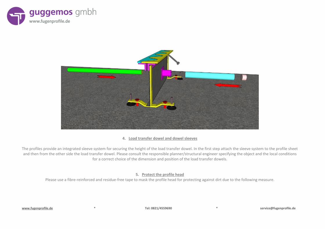
4. Load transfer dowel and dowel sleeves
The profiles provide an integrated sleeve system for securing the height of the load transfer dowel. In the first step attach the sleeve system to the profile sheet and then from the other side the load transfer dowel. Please consult the responsible planner/structural engineer specifying the object and the local conditions
for a correct choice of the dimension and position of the load transfer dowels.
5. Protect the profile head Please use a fibre-reinforced and residue-free tape to mask the profile head for protecting against dirt due to the following measure.
www.fugenprofile.de * Tel: 0821/4559690 * [email protected]
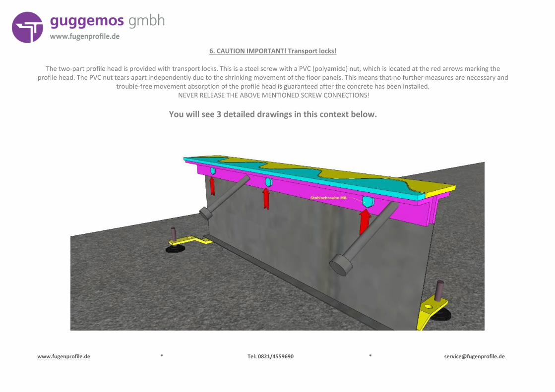
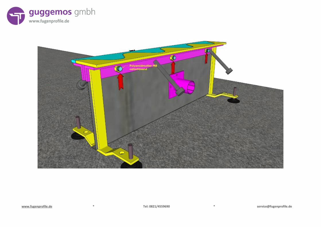
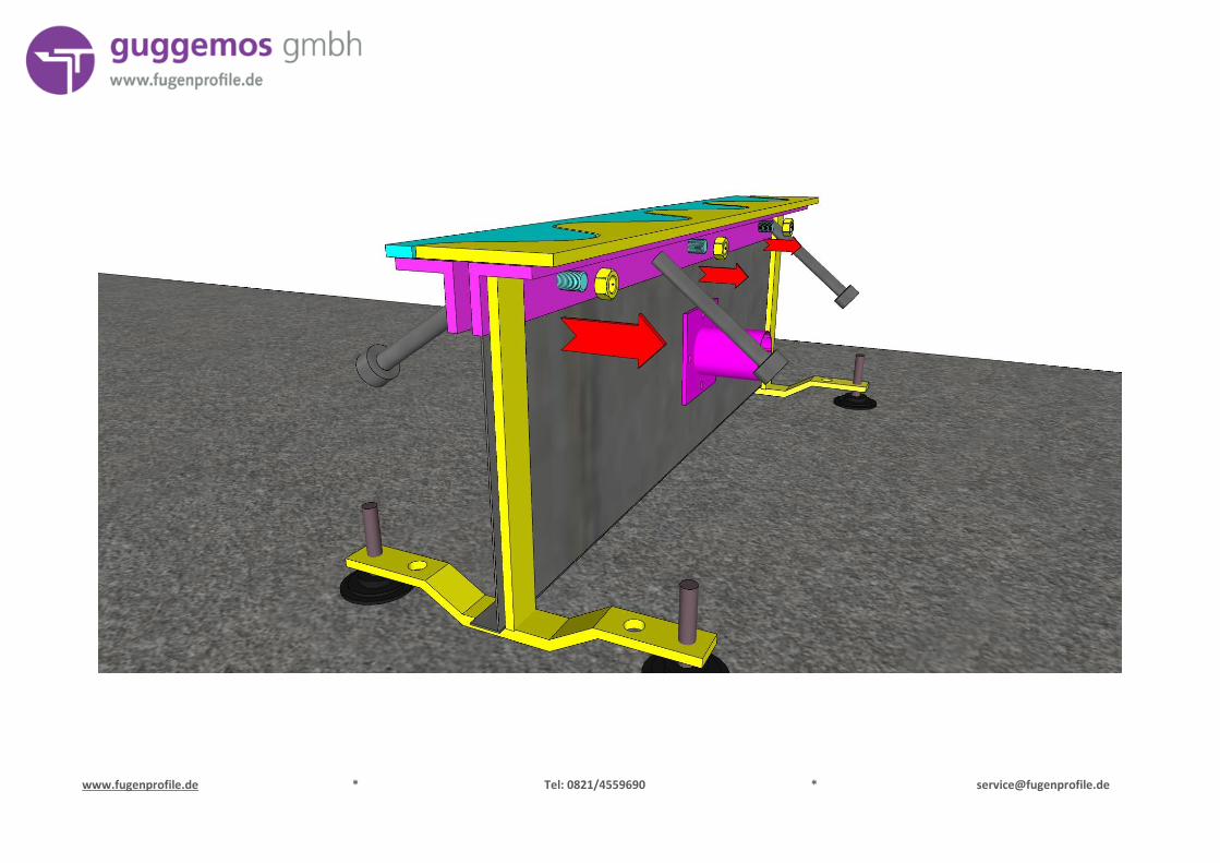
6. CAUTION IMPORTANT! Transport locks!
The two-part profile head is provided with transport locks. This is a steel screw with a PVC (polyamide) nut, which is located at the red arrows marking the profile head. The PVC nut tears apart independently due to the shrinking movement of the floor panels. This means that no further measures are necessary and
trouble-free movement absorption of the profile head is guaranteed after the concrete has been installed. NEVER RELEASE THE ABOVE MENTIONED SCREW CONNECTIONS!
You will see 3 detailed drawings in this context below.
www.fugenprofile.de * Tel: 0821/4559690 * [email protected]
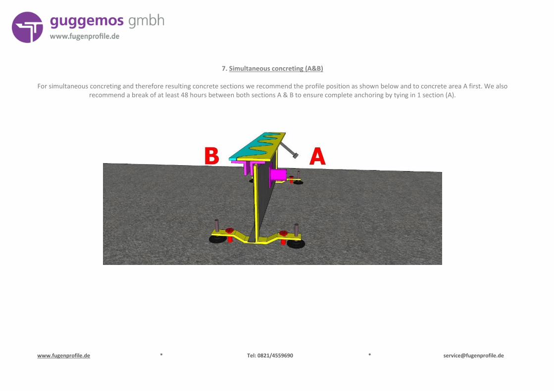
7. Simultaneous concreting (A&B)
For simultaneous concreting and therefore resulting concrete sections we recommend the profile position as shown below and to concrete area A first. We also recommend a break of at least 48 hours between both sections A & B to ensure complete anchoring by tying in 1 section (A).
www.fugenprofile.de * Tel: 0821/4559690 * [email protected]
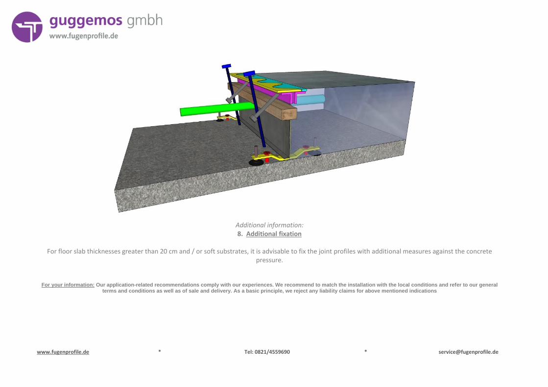
Additional information: 8. Additional fixation
For floor slab thicknesses greater than 20 cm and / or soft substrates, it is advisable to fix the joint profiles with additional measures against the concrete
pressure.
For your information: Our application-related recommendations comply with our experiences. We recommend to match the installation with the local conditions and refer to our general terms and conditions as well as of sale and delivery. As a basic principle, we reject any liability claims for above mentioned indications