installation design guidelines for coca-cola freestyle
TRANSCRIPT

These Guidelines have been prepared to help meet the needs of those designing
facilities utilizing Coca-Cola Freestyle® 7000 beverage dispensing equipment. For
more information, consult with your Coca-Cola representative.
Design Specifications:
Water Supply System:
• 1/2” dedicated copper supply line with a separate shutoff valve must be located
within 6 feet of the water booster and filtration system.
• Shutoff should end with a ½” I.D. female pipe fitting or a 3/8” O.D. male flare fitting
or a 3/8” compression fitting.
• Ambient or cold, un-softened water.
• Minimum of 40 psi at 120 GPH (gallons per hour) dispensing system for incoming
water pressure.
• If the water pressure exceeds 120 psi, use a water regulator set at 80 psi.
Water Filtration System:
• Water filtration systems will be required. The Coca-Cola Company will work with
the customer for the proper program for water filtration and filter cartridge
replacement.
• If the customer is providing water filtration, the filters must meet NSF Standard 42.
• Size the filters to meet the maximum instantaneous demand of the downstream
equipment.
• Dispensing system requires approximately 120 gallons GPH (gallons per dispenser)
(or 1.67 gallons per minute) when operating.
• System should have a filter bypass option.
Backflow Prevention:
• Dispensing systems are provided with ASEE 1022 backflow prevention devices.
• Additional cross connection backflow prevention assemblies that are required by
some municipalities are the responsibility of the outlet. These assemblies must be
installed by an authorized trade and not Coca-Cola installers.
Classified - Confidential
Installation Design Guidelines for Coca-Cola Freestyle® 7000
for Architects, Engineers, and Contractors
1 3/23/2015

Classified - Confidential
Design Specifications:
Water Boosters:
• Water Booster is not required, unless the water pressure is too low. Too low is
defined as <40 psi dynamic/flowing.
• Pre-installation Site Assessment will provide input on this decision.
• Water boosters must be installed AFTER the pre-filter (if used) but prior to the
chlorine reduction filter.
• Water Booster must not be located after the filter system. The intention is for
boosted pressure to flow through the filter, i.e., push rather than pull water
through the filter system.
• Water booster should be off the floor, out of any wash-down area, within 6' of the
½” main water supply.
• Location of the water booster atop HFCS BIB rack is highly recommended and can
be provided by The Coca-Cola Company if HFCS(sweetener) will utilize a rack.
• One standard 2.5 gallon water booster can support one (1) Freestyle 7000 dispensing
system. For outlets with two Freestyle 7000 units, or additional non-carbonated
system, i.e., tea, coffee, etc., a 4.4 gallon water booster is recommended.
• A Coca-Cola representative will assist with sizing of the water booster.
• Maximum line run for a 2.5 and 4.4 gallon water booster is 150 feet.
• The space requirement for a 2.5 and 4.4 gallon water booster is: 16.49" wide x
18.24" deep and 12.19” high. These dimensions do not include access for service.
• Wet weight of water booster is approximately 75 lbs.
Electrical:
• Dispenser: Use a separate 115 volt, 20 amp, and grounded receptacle for each
dispenser.
• Outlet must be within 4 feet of the dispenser and water booster areas.
• Never plug Freestyle unit or water booster into a GFI protected outlet or circuit.
• Water Booster: Electrical Requirements: 115V/60Hz/1 Ph. /15 amp grounded
receptacle, 1/3 HP Motor, 7 Amp.
• These electrical requirements do not include any electrical requirements for ice
makers that may be installed on top of the dispenser. Those requirements are
dependent on the ice maker that is chosen by the outlet.
• Ice makers will require their own separate electrical outlet and circuit.
Installation Design Guidelines for Coca-Cola Freestyle® 7000
for Architects, Engineers, and Contractors
2 3/23/2015

Design Specifications:
Drains:
• 3" or larger floor drain “should” be located within 3 feet of the Freestyle
dispenser.
• The preferred drain is an open floor sink with a center cone located centered
behind the rear of the dispenser.
• Do not use copper for soft-drink drains.
• Drains requirements for post-mix equipment will vary locally.
• Compliance with local code is the responsibility of outlet ownership.
• Be aware that there often can be no direct connection between the sewage system
and any drains originating from equipment in which food or utensils are placed.
Food includes ice.
• In some jurisdictions, an acceptable manner to install a drain from an ice bin is to
have the drain have a standard vertical air gap (2 times the diameter of drain pipe)
between it and the floor drain.
• See your Coca-Cola Representative for exceptions.
Classified - Confidential
Floor Drain
Gap=2’ x D(p)
3
Installation Design Guidelines for Coca-Cola Freestyle® 7000
for Architects, Engineers, and Contractors
3/23/2015

Classified - Confidential
Design Specifications:
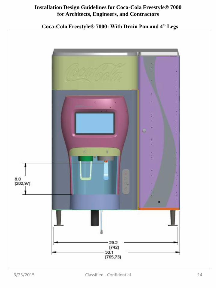
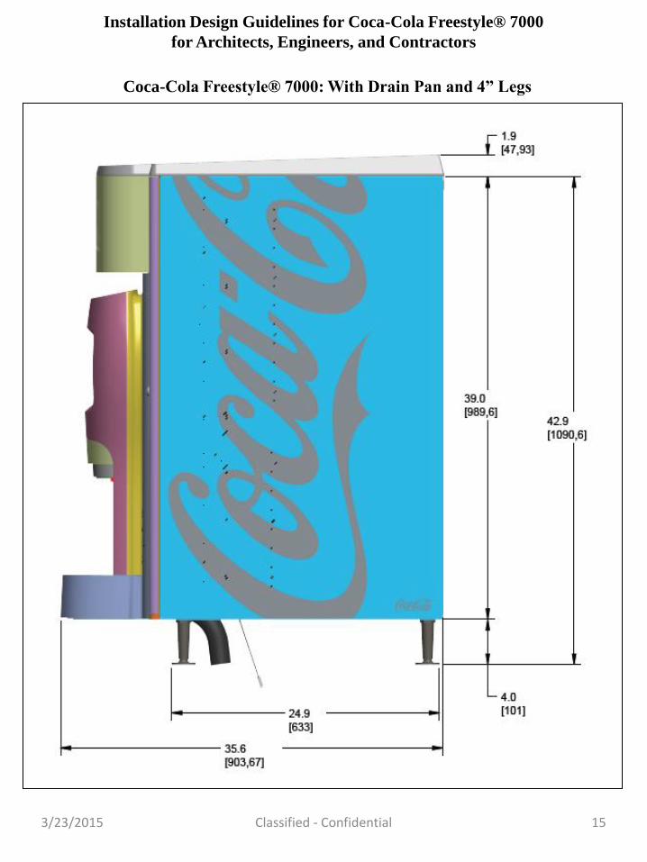
Maximum Dimensions:
• The design of the dispensing area should avoid adding heat from any external
source. There should be adequate insulation from heat lamps, ovens, broilers,
compressor exhausts, and the like.
• With 4” Legs, Drain Pan: W: 30 1/8” x D: 35 11/16” x H: 43”
• Without Legs, Without Drain Pan: W: 30 1/8” x D: 33 3/8” x H: 39”
• See pages 13-18 for additional dimensions and diagrams
Type of
Dispenser
Maximum
Width
Maximum
Depth
With
Drain Pan
Maximum
Depth
Without
Drain Pan
Height Clearance* Dispenser
Weight
7000
Dispenser 30 1/8” 35 11/16” 33 3/8”
39” w/o
legs
43” with
legs
Sides 2”
Rear 0”-4”
Dry:
375 Lbs.
Full:
625 Lbs. 4
Installation Design Guidelines for Coca-Cola Freestyle® 7000
for Architects, Engineers, and Contractors
3/23/2015

Classified - Confidential
Design Specifications:
Weight:
Counter must support 625 lbs.* to include dispenser, water, product and ice in the
dispenser.
*Includes the full fluids including product, HFCS, water, accessories, and additional
items.
An additional 150-200 lbs. should be included when adding a top-mount ice-maker
to the dispenser.
There will be 4 load bearing legs to distribute the weight of the dispenser to the
counter.
Allow clearance in front of the dispenser for approach and any queuing needs.
Insure adequate clearance for wheelchair approach.
There should be counter space or a tray rail adjacent to the dispenser for consumers
to rest a food tray if desired.
Allow space above the dispenser for loading ice manually and adequate clearance if
an icemaker is installed on top. See Ice Maker Manufacturer guidelines prior to
installation to avoid any possible delays at time of installation.
Clearances:
• Side: 2”(both sides); Rear: 0”-4”*
*See counter depth requirements with and without ice maker
Ice Bin Capacity:
• Full Bin: 200-220 lbs. Dispensable: 180-190 lbs.*
*Final bin capacity may vary depending upon placement of ice maker bin stat
control.
5
Installation Design Guidelines for Coca-Cola Freestyle® 7000
for Architects, Engineers, and Contractors
3/23/2015

Design Specifications:
Wireless Access:
• It is mandatory that all Coca-Cola Freestyle® 7000 dispensers be connected to a
cellular network for software and recipe updates and data downloads. For more
information, consult with your Coca-Cola representative.
Three options for connectivity:
• A: Wireless (Preferred): The cell signal strength of the Coca-Cola provided
Network Provider must be between -80 dBm & -95 dBm for this option to work.
• B: Wireless with external modem: When local signal strength is marginal,
between -95 dBm and 105 dBm, Coca-Cola will install an external modem (at no
cost to the operator) in an attempt to boost the local cellular signal within the
outlet. If unsuccessful with obtaining a consistent and reliable cellular connection a
Wired Solution must be installed by the customer (see diagram below).
• C: Wired: An Ethernet cable terminated into a RJ45 jack must be located within 6
feet of the dispenser. For more information, consult with your Coca-Cola
representative.
Classified - Confidential 6
Cell Tower Internet
Installation Design Guidelines for Coca-Cola Freestyle® 7000
for Architects, Engineers, and Contractors
3/23/2015

Classified - Confidential
Design Specifications:
Ice Makers:
• Size ice making equipment properly. Usage for soft-drinks may vary from 0.8
pounds per cup to 1.4 pounds per cup, depending on equipment selected and cup
set.
• Hard cubed ice is required for all dispenser units.
• If compressed “cublet” ice is used, the ice quality rating should be a minimum of
88.
• Do not use super-cooled ice (ice from a commercial freezer, i.e., bagged ice).
Super-cooled ice causes drinks to foam and may damage cold-plate and ice
dispensing systems.
• Use ice as produced from the ice maker and stored in an insulated bin.
• Contact your Coca-Cola representative with questions concerning approved ice
maker models and ice types, i.e., soft, etc.
7
Installation Design Guidelines for Coca-Cola Freestyle® 7000
for Architects, Engineers, and Contractors
3/23/2015
Classified - Confidential
Design Specifications:
Chases:
• If a conduit (tube transport or chase) is to be used to house beverage tubing the
minimum inside diameter of the conduit should 6“ with smooth interior joints.
• This conduit size will support up to 3 dispensers with a maximum run length of 150
feet. For more dispensers or longer run lengths, larger conduit sizes or multiple
conduits are recommended.
• Conduits should have sweeping elbows, not 90 ° elbows. The conduit should end at
least 3" above the floor surface to prevent any water from entering the conduit.
• Syrup and water must be protected from freezing. Do not run tubing through areas
subject to freezing, even if the tubing is insulated, i.e., unheated ceiling, etc.
• Beverage tubing must be insulated if running through areas which are above 95°F.
High temperatures are most likely in ceilings or in uninsulated exterior walls.
Insulated tubing will require larger than standard conduits.
• Stainless steel beverage tubing must be used where water (condensation) can
accumulate. This generally means all underfloor chases.
• Use only barrier plastic beverage tubing approved by Coca-Cola Fountain or
stainless steel beverage tubing.
Co2 Systems:
• There are 2 types of CO2 system – bottle tanks and bulk supply.
• Typical bulk CO2 tanks are 16 to 24 inches in diameter and require connection to fill
and vent access on an outside wall.
• Typical CO2 tanks are 7 to 10 inches in diameter. A minimum of two tanks are
required if not using bulk CO2.
• On bulk CO2 tanks ensure vaporizing and regulator capacity is sufficient (3 scfm per
dispenser).
• Watch average versus instantaneous requirements.
• If tank CO2 is to be located under the counter, 30” under-counter clearance is
required.
• CO2 tanks must be located next to a solid surface and chained in the upright
position.
• CO2 storage areas must be open and well ventilated.
• One regulator set per dispenser system is required. The regulator set should come
with the beverage system and may be mounted on the BIB rack or wall.
8
Installation Design Guidelines for Coca-Cola Freestyle® 7000
for Architects, Engineers, and Contractors
3/23/2015

Classified - Confidential
Design Specifications:
Sweetener System:
• The HFCS sweetener will be provided in 5-Gallon BIB form.
• The HFCS BIB is located outside of the dispenser on a BIB rack either underneath
counter or in the backroom.
• The ideal storage temperature for HFCS (sweetener) is between 60°F and 75°F.
• Sweetener cannot be stored in rooms exceeding 95°F or below 55°F. Note:
• Sweetener should never be placed in a walk-in cooler or freezer.
• The size of the rack is dependent on the volume of the outlet.
• The minimum footprint for a BIB product platform rack is 18" deep x either 16” or
30" wide (including clearance).
• A Coca-Cola representative will assist with sizing of the rack. Some installations
use a BIB rack that have pumps, selectors, and a CO2 regulator set assembly
mounted directly to the rack. Other options may require an under counter
installation and single wide BIB rack.
Non-Nutrative Sweetener(NNS):
• NNS – Cartridge located inside dispenser (future NNS innovation may require under
counter space).
Coca-Cola
Freestyle®
Inclined BIB
Rack 15”:
W: 15.64”
D: 16.08”
H: 77.39”
Coca-Cola
Freestyle®
Inclined BIB
Rack 28”
W: 28.43”
D: 16.08”
H: 77.39”
9
15” Wide Single BIB Rack
28” Wide Double BIB Rack
Single BIB Rack
Installation Design Guidelines for Coca-Cola Freestyle® 7000
for Architects, Engineers, and Contractors
3/23/2015
Double BIB Rack

Classified - Confidential
Design Specifications:
Counter Depth Guidelines:
• The following will serve to answer questions about counter depth requirements
when installing Coca-Cola Freestyle® 7000 with Drain Pan and 4” Legs.
• If planning to install Freestyle 7000 with a top-mount ice maker, customers should
confirm clearance requirements with their respective ice maker manufacturer and
then advise Coca-Cola on how they want to proceed.
• Minimum Recommended Counter Depths apply regardless of whether
dispensers are mounted on legs or not. Note – If dispenser is planned to be
mounted directly on the counter, customers should consider whether there is a lip
on the edge of their counter to allow for a 1” set-back. A set-back of 1” ensures
that dispensers front legs or front edge sit an acceptable distance back from the
front edge.
What is the minimum counter depth for Freestyle 7000 when installed without an
ice maker?
• 28” Minimum Counter Depth is Required
• How we get to 28”: 25” between dispenser legs
1” between Rear of Dispenser and Back Legs
1” Between Front Legs and Counter Edge
0-1” Space at Rear of Dispenser..
10
Installation Design Guidelines for Coca-Cola Freestyle® 7000
for Architects, Engineers, and Contractors
3/23/2015

Classified - Confidential
Design Specifications:
Counter Depth Guidelines:
What is the minimum counter depth for Freestyle 7000 when installed with an ice
maker?
• 28” - 32” Minimum Counter Depth is Required
• How we get to 28”- 32”: 25” between dispenser legs
1” between Rear of Dispenser and Back Legs
1” Between Front Legs and Counter Edge
1-4” Space at Rear of Dispenser.
11
Installation Design Guidelines for Coca-Cola Freestyle® 7000
for Architects, Engineers, and Contractors
3/23/2015
Counter Depth Guidelines:
• The amount of space left at rear of dispenser and back wall should be a customer
decision based upon ice maker manufacturer recommendations for appropriate air
flow behind and around ice maker. Ice makers equipped with “remote or water”
cooled condensers generally have different, i.e., reduced, clearance requirements.
• Customers should confirm “ideal and minimum” space requirements with ice maker
manufacturer prior to confirming installation with Coca-Cola.

Classified - Confidential
Coca-Cola Freestyle® 7000: With Drain Pan and 4” Legs
12
Installation Design Guidelines for Coca-Cola Freestyle® 7000
for Architects, Engineers, and Contractors
3/23/2015

Classified - Confidential 13
Coca-Cola Freestyle® 7000: With Drain Pan and 4” Legs
Installation Design Guidelines for Coca-Cola Freestyle® 7000
for Architects, Engineers, and Contractors
3/23/2015
Classified - Confidential 14
Coca-Cola Freestyle® 7000: With Drain Pan and 4” Legs
Installation Design Guidelines for Coca-Cola Freestyle® 7000
for Architects, Engineers, and Contractors
3/23/2015
Classified - Confidential 15
Coca-Cola Freestyle® 7000: With Drain Pan and 4” Legs
Installation Design Guidelines for Coca-Cola Freestyle® 7000
for Architects, Engineers, and Contractors
3/23/2015

Classified - Confidential
Coca-Cola Freestyle® 7000: With Extended Splash Plate
16
Installation Design Guidelines for Coca-Cola Freestyle® 7000
for Architects, Engineers, and Contractors
3/23/2015

Classified - Confidential
Coca-Cola Freestyle® 7000: With Extended Splash Plate
17
Installation Design Guidelines for Coca-Cola Freestyle® 7000
for Architects, Engineers, and Contractors
3/23/2015
Classified - Confidential
This manual is furnished on the condition that the user assumes all risks and liabilities
arising out of the use, non-use, misuse or reliance on this manual. The Coca-Cola
Company does not warrant suitability, favorable results, or compliance with all
applicable laws, rules and regulations, such as, for example, but not limited to the
"Americans with Disabilities Act".
The Coca-Cola Company does not warrant that use of this manual will be free from
infringement of any industrial property right of any third party. Further, The Coca-
Cola Company does not endorse or guarantee the equipment installed hereunder and
shall not be liable or responsible for any loss, claims, or damage, direct or
consequential, arising out of the use, non-use, or reliance on this manual.
©2015 The Coca-Cola Company. This manual is not to be duplicated or released, in
whole or in part, without the express written permission of The Coca-Cola Company,
which reserves the right to make changes hereto without notice to recipients of this
manual.
18
Installation Design Guidelines for Coca-Cola Freestyle® 7000
for Architects, Engineers, and Contractors
3/23/2015