installation instructions for …greenstreetaudio.com/pages/instructions.pdf200 v capacitor, use a...
TRANSCRIPT
INSTALLATION INSTRUCTIONS FOR GREENSTREET AUDIO KITS
The voltage in your amplifier can exceed 360v and is potentially lethal. Before removing the cover, read and understand the safety guidelines that follow. It is really worth the time.
Safety Guidelines These guidelines are to protect you from potentially deadly electrical shock hazards as well as the equipment from accidental damage. Note that the danger to you is not only in your body providing a conducting path, particularly through your heart. Any involuntary muscle contractions caused by a shock may cause collateral damage. There are likely to be many sharp edges and points inside from various things like stamped sheet metal shields and the cut ends of component leads on the solder side of printed wiring boards in this type of equipment. In addition, the reflex may result in contact with other electrically live parts and further unfortunate consequences. The purpose of this set of guidelines is not to frighten you but rather to make you aware of the appropriate precautions. Repair of audio equipment, TVs, monitors, microwave ovens, and other consumer and industrial equipment can be both rewarding and economical. Just be sure that it is also safe!
• Don't work alone - in the event of an emergency another person's presence may be essential. • Always keep one hand in your pocket when anywhere around a powered line-connected or high voltage
system. • Wear rubber bottom shoes or sneakers. An insulated floor is better than metal or bare concrete but this
may be outside of your control. A rubber mat should be an acceptable substitute but a carpet, not matter how thick, may not be a particularly good insulator.
• Wear eye protection - large plastic eyeglasses or safety goggles. • Don't wear any jewelry or other articles that could accidentally contact circuitry and conduct current, or get
caught in moving parts. • Set up your work area away from possible grounds that you may accidentally contact. • Have a fire extinguisher rated for electrical fires readily accessible in a location that won't get blocked
should something burst into flames. • Use a dust mask when cleaning inside electronic equipment and appliances, particularly TVs, monitors,
vacuum cleaners, and other dust collectors. • Know your equipment: TVs and monitors may use parts of the metal chassis as ground return yet the
chassis may be electrically live with respect to the earth ground of the AC line. Microwave ovens use the chassis as ground return for the high voltage. In addition, do not assume that the chassis is a suitable ground for your test equipment!
• If circuit boards need to be removed from their mountings, put insulating material between the boards and anything they may short to. Hold them in place with string or electrical tape. Prop them up with insulation sticks - plastic or wood.
• If you need to probe, solder, or otherwise touch circuits with power off, discharge (across) large power supply filter capacitors with a 2 W or greater resistor of 100 to 500 ohms/V approximate value (e.g., for a 200 V capacitor, use a 20K to 100K ohm resistor). Monitor while discharging and/or verify that there is no residual charge with a suitable voltmeter. Connect/disconnect any test leads with the equipment unpowered and unplugged. Use clip leads or solder temporary wires to reach cramped locations or difficult to access locations.

• If you must probe live, put electrical tape over all but the last 1/16" of the test probes to avoid the possibility of an accidental short, which could cause damage to various components. Clip the reference end of the meter or scope to the appropriate ground return so that you need to only probe with one hand.
• Perform as many tests as possible with power off and the equipment unplugged. For example, the semiconductors in the power supply section of a TV or monitor can be tested for short circuits with an ohmmeter.
• Use an isolation transformer if there is any chance of contacting line connected circuits. A Variac(tm) (variable autotransformer) is not an isolation transformer! However, the combination of a Variac and isolation transformer maintains the safety benefits and is a very versatile device
• The use of a GFCI (Ground Fault Circuit Interrupter) protected outlet is a good idea but may not protect you from shock from many points in a line connected TV or monitor, or the high voltage side of a microwave oven, for example. (Note however, that a GFCI may nuisance trip at power-on or at other random times due to leakage paths (like your scope probe ground) or the highly capacitive or inductive input characteristics of line powered equipment.) A GFCI is also a relatively complex active device, which may not be designed for repeated tripping You are depending on some action to be taken (and bad things happen if it doesn't!) - unlike the passive nature of an isolation transformer. A fuse or circuit breaker is too slow and insensitive to provide any protection for you or in many cases, your equipment. However, these devices may save your scope probe ground wire should you accidentally connect it to a live chassis.
• When handling static sensitive components, an anti-static wrist strap is recommended. However, it should be constructed of high resistance materials with a high resistance path between you and the chassis (greater than 100K ohms). Never use metallic conductors as you would then become an excellent path to ground for line current.
• Don't attempt repair work when you are tired. Not only will you be more careless, your primary diagnostic tool - deductive reasoning - will not be operating at full capacity.
• Finally, never assume anything without checking it out for yourself! Don't take shortcuts!
Safety Tests for Leakage Current on Repaired Equipment It is always essential to test AFTER any repairs to assure that no accessible parts of the equipment have inadvertently been shorted to a HOT wire or live point in the power supply. In addition to incorrect rewiring, this could result from a faulty part, solder splash, or kinked wire insulation. There are two sets of tests:
• DC leakage: Use a multimeter on the highest OHMS range to measure the resistance between the Hot/Neutral prongs of the wall plug (shorted together and with the power switch on where one exists) to ALL exposed metal parts of the equipment including metallic trim, knobs, connector shells and shields, VHF and UHF antenna connections, etc. This resistance must not be less than 1 M ohm.
• AC leakage: Connect a 1.5K ohm, 10 Watt resistor in parallel with a 0.15 uF, 150 V capacitor to act as a load. Attach this combination between the probes of your multimeter. With the equipment powered up, check between a known earth ground and each exposed metal part of the equipment as above. WARNING: Take care not to touch anything until you have confirmed that the leakage is acceptable - you could have a shocking experience! The potential measured for any exposed metal surface must not exceed 0.75 V. This corresponds to a maximum leakage current of 0.5 mA. Note: A true RMS reading multimeter should be used for this test, especially where the equipment uses a switchmode power supply, which may result in very non-sinusoidal leakage current.
If the equipment fails either of these tests, the fault MUST be found and corrected before putting it back in service Checking for correct hookup of the Hot, Neutral, and Ground wires to the AC plug should also be standard procedure. There's no telling how it may have been scrambled during a previous attempt at repair. Unlike color coding for logic circuits, black is NOT the standard color for ground in electric wiring!

Tools and materials:
You will need wire cutters, wire strippers, assorted screwdrivers, a soldering iron, a quality multimeter, test leads with clips, safety glasses, a few 1amp fuses, a quantity of five, 2-watt 1-ohm resistors, solder, thermal grease, and silicone adhesive. All of these are available at Radio Shack if you do not own them already. The one specialized tool you will need is an autotransformer, sometimes called a Variac. It is a variable transformer and will be used during the adjustment of the amplifier after assembly is complete. If you do not own one, they can be purchased new or used on eBay for $20.00 on up, depending on the size. The adjustments will be made with no load on the amplifier, so a small 1 amp variac will do the job.
Step 1: Removing the circuit board.
• Unplug the amplifier. • Only if you have read and understand the safety guidelines, remove the top cover. • Discharge the large blue capacitors next to the transformer as per the safety guidelines. • Remove the tubes. • Disconnect the 4 leads to the RCA input jacks on the rear panel of the amplifier.
Break the connection at the jack to prevent damage to the circuit board. It is highly recommended the jacks be replaced with high quality units at this time.
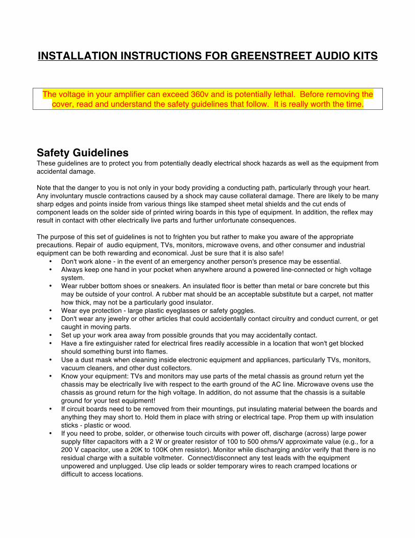
• Remove all eight MOSFETs and free the connectors from the heatsinks • Disconnect slide on spades from R, -6, and G terminals of the LED driver. Label
each for identification during reassembly. • Unscrew Q1 and Q101 from the heatsinks (see Figure-4). These will be reused.
Label the wires B, C, E before clipping them from the circuit board. • Unscrew the chassis ground wire on the rear panel. Itʼs a white wire that runs
under the circuit board and is screwed below the RCA input jacks. • Remove the wire ties that bundle the white wires attached to the large blue
capacitors next to the transformer and separate the wires to determine which wire goes where. Figure-3 shows the wires with the ties removed with labels to help sort out the wires.
• When you have identified the white wires that are soldered to the GND, -40, and +40 terminals shown in Figure-1, detach them from the screws on the bar connecting the capacitors.
• When you have identified the white wires that are soldered to the GND terminal shown in Figure-2, detach them from the screws on the bar connecting the capacitors.
• The SA-100 transformer has 10 wires from the secondary coils. The SA-12 may have 10 or 8 depending on its manufacture date. The color codes are: Red and red/black carrying 270 volts; yellow and yellow/black carrying 9 volts; and a pair of green and green/black with a green/yellow ground carrying 80 volts, one for each channel.
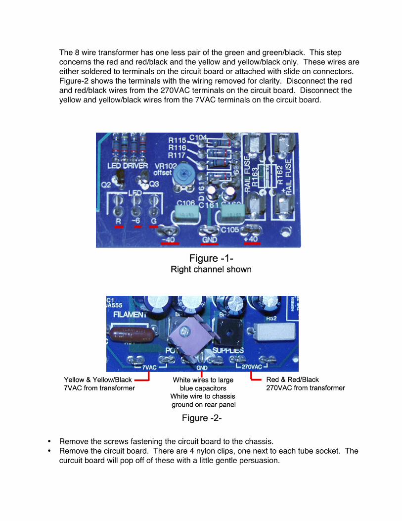
The 8 wire transformer has one less pair of the green and green/black. This step concerns the red and red/black and the yellow and yellow/black only. These wires are either soldered to terminals on the circuit board or attached with slide on connectors. Figure-2 shows the terminals with the wiring removed for clarity. Disconnect the red and red/black wires from the 270VAC terminals on the circuit board. Disconnect the yellow and yellow/black wires from the 7VAC terminals on the circuit board.
• Remove the screws fastening the circuit board to the chassis. • Remove the circuit board. There are 4 nylon clips, one next to each tube socket. The
curcuit board will pop off of these with a little gentle persuasion.
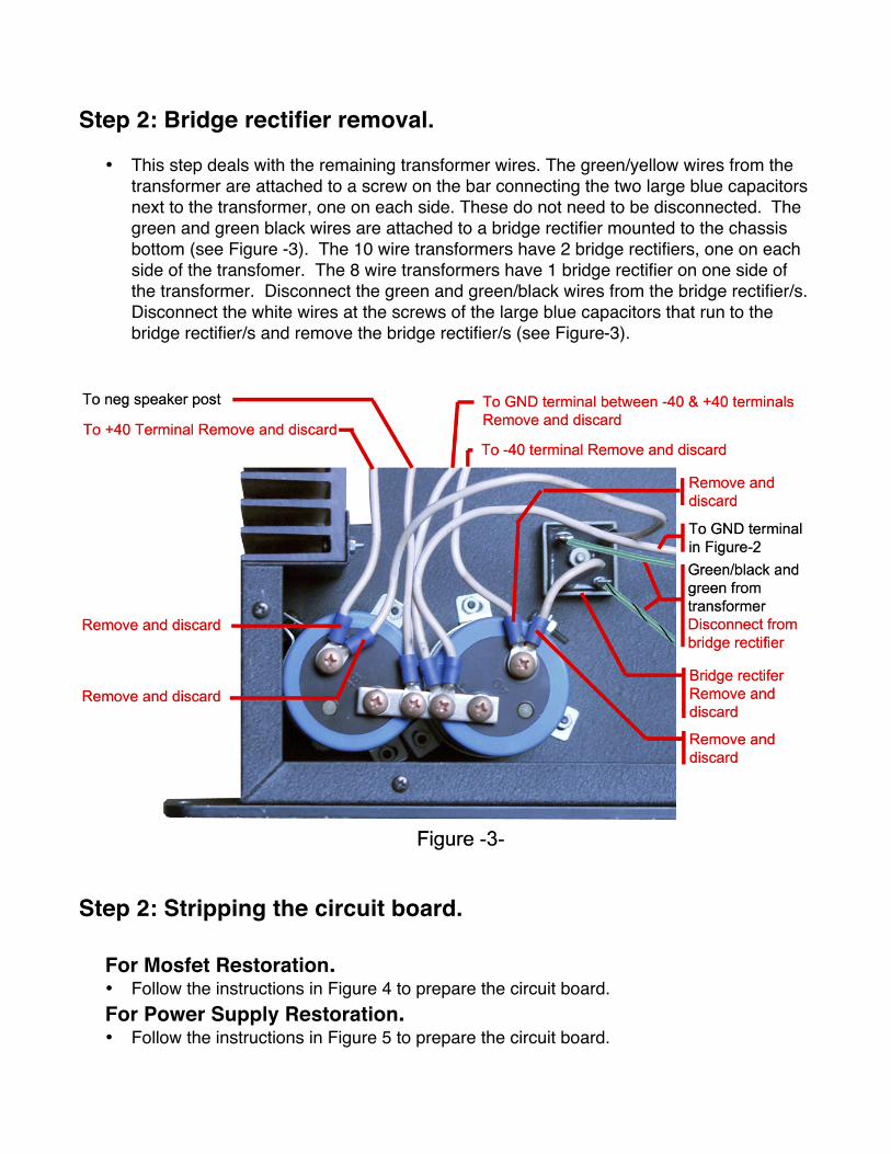
Step 2: Bridge rectifier removal.
• This step deals with the remaining transformer wires. The green/yellow wires from the transformer are attached to a screw on the bar connecting the two large blue capacitors next to the transformer, one on each side. These do not need to be disconnected. The green and green black wires are attached to a bridge rectifier mounted to the chassis bottom (see Figure -3). The 10 wire transformers have 2 bridge rectifiers, one on each side of the transfomer. The 8 wire transformers have 1 bridge rectifier on one side of the transformer. Disconnect the green and green/black wires from the bridge rectifier/s. Disconnect the white wires at the screws of the large blue capacitors that run to the bridge rectifier/s and remove the bridge rectifier/s (see Figure-3).
Step 2: Stripping the circuit board.
For Mosfet Restoration. • Follow the instructions in Figure 4 to prepare the circuit board. For Power Supply Restoration. • Follow the instructions in Figure 5 to prepare the circuit board.

Step 3: Reinstall Circuit Board. • Snap the circuit board on to the four nylon pins. • Reinstall the screws. • If you are not installing a new Power Supply Restoration board, solder the red,
red/black, yellow, and yellow/black wires from the transformer on to their respective terminals. If your amplifier has slide on connectors, clip them off and solder the wires to the terminals. If you are also installing a new Power Supply Restoration board leave these wires disconnected until step 5.
• Solder the 4 leads on to the new RCA input jacks you installed on the rear panels. Step 4: Install the MOSFET Boards:
• An anti-static wrist band should be worn during the MOSFET board installation. • Solder the wire leads from Q1 and Q101 to the C, B, and E pads on the new MOSFET
boards. These are very small wires going into very small holes. After soldering them in place, use a magnifier to examine the solder joints to be sure there are no stray strands of wire, or solder bridges between the pads.
• Place a small amount of thermal grease on the back of the MOSFET and slide a insulation pad over the protruding screw. Place a small amount of thermal grease on the insulation pad.
• Insert the 4 screws sticking out of the back of the MOSFET board through the outer most holes in the heatsink. Place washers and nuts on each screw and tighten with a #1 phillips head screwdriver.
• Apply a small amount of thermal grease to the flat ends of Q1 and Q101. Fit them through the hole in the new MOSFET board and screw them to the heatsinks.
• Figure-6 shows the pad on the Counterpoint circuit board where the lead labeled “Gate” is to be connected. Solder the Gate wire to the pad.
• Figure-6 shows the pad on the Counterpoint circuit board where the lead labeled “Relay” is to be connected. The Relay wire is longer than necessary and can be trimmed to route it neatly. Trim it to length and solder it to the pad.
• Splice and solder the wire labeled “Green” and the wire labeled “Green/Black” to the green and green/black wires from the transformer respectively. These wires are longer than necessary and can be trimmed to route them neatly. Insulate the splces with heat shrink tubing or electical tape.
• Attach the wire labeled “Speaker” to the positive binding post. • Using the existing screw, attach the wire labeled “Ground” to the bar connecting the two
large blue capacitors along with the white wire from the GND terminal in Figure-2 that was disconnected earlier. Both of these wires should be on the same screw as the green/yellow wire from the transformer.

• On each pair of connected large blue capacitors there should now be two screws without wires attached, one on each capacitor. Molded into the plastic top of each capacitor will be a + or – symbol next to the open screw terminals. Attach the wire labeled “+” on the + terminal and the wire labeled “–“ on the – terminal using the existing screw. THIS IS VERY IMPORTANT – double check your work and make sure the positve wire is connected to the positive screw and the negative wire is connected to the negative screw. If you power the amplifier with these reversed it can cause serious damage to amplifer and possibly to you as well.
• Repeat the proceedure for the other channel. Step 5: Install the Power Supply Board:
• Before mounting the board, solder the transformer wires to the pads at the bottom.
Yellow to pad Vac 7a, yellow/black to pad Vac 7b, red to pad Vac 250a, and red/black to pad 250b.
• Apply a bead of silicon adhesive to the underside the board. The bead should be of sufficient thickness to hold the board at least 3mm above the main board. The power supply board has a notch cut in the bottom edge in the center of a rectangular solder pad. Fit this notch around the remaining vertical terminal of GND shown in Figure-5 and adhere the new board to the existing. Check and make sure there is at least 3mm of space between the two boards. We recommend placing 3mm thick shims made of non-conductive material under the edges of the new board until the silicone has cured. Position the new board to assure that the pads on the orginal board, to which new leadsA,B, and C will attach, are not under the new board (see Figure-5)
• After the silicon has fully cured (24 hours), solder leads 1, 2, and 3 to the pads shown in figure 5.
• Solder the vertical GND terminal to the slotted pad in the new board. • Solder the two white wires previously removed to the remaining verical GND terminal.
Powering up and adjusting the bias: The bias network must be adjusted before the amplifier can be used. Measurements will be taken with the amplifier powered, with voltages present that can be as high as 350v. Follow the safety procedures outlined on the first page.
• The bias networks for each channel will be adjusted one at a time. If you have installed the four rail fuses (two on each board) they must be removed. Do not remove the speaker fuse
• Install a 1 amp fuse in the clip labeled5A N Fuse. • Install the tubes.

• You will need a few 2-watt 1-ohm resistors. Check each one with a multimeter and choose the resistor closest to 1ohm. This resistor will replace the fuse labeled 5A P in the circuit and will be used to measure the output stage's bias current.
• Clip a test lead to each of the 5A P Fuse clips on one of the channels MOSFET boards. Make sure the insulating boot of the test lead is covering the exposed clip. Clip the other ends of the test leads to each end of the 1ohm resistor and lay it on the table next to the amplifier where you can get to it easily and it will not come in contact with the amplifier chassis.
• Clip the probes of a multimeter to each side of the 1ohm resistor and set it to DC volts. This will measure the voltage drop across the resistor and therefore, the equivalent current (if you want to know why, look up Ohmʼs Law)
• A second multimeter will make the process easier if you own one, but it is not absolutely necessary. If you have a second one, place the probes on the positive and negative speaker terminals of the channel you are adjusting and set it to DC volts. This will measure the DC offset. If you have only one mutimeter, you will need to switch it back and forth between the 1ohm resistor and the speaker terminals as outlined in the next steps. You will need to power down the amplifier and drain capacitors at every switch.
• The moment of truth. Set the Variac at zero and plug the amplifier into the Variac output. Switch on the Variac and switch on the amplifier.
• Slowly dial up the Variac to 20%. The multimeter attached to the resistor should not rise above 10mV if it rises above 0.00 at all. If it does, turn everything off and check your wiring and solder joints, something was wired incorrectly.
• If you do not have a second multimeter, Unplug the amplifier, discharge the big blue capacitors next to the transformer as per the safety guidelines, and disconnect the meter attached to the 1ohm resistor and place the probes across the speaker posts of the channel being adjusted. Set the Variac to 0, power the amplifier, and slowly dial up the Variac to 50%. If the DC offset is more than 5 volts, it indicates a fault in the wiring and the problem must be corrected before continuing. The DC offset will bounce around quite a bit and never truly settle down to a steady measurement, so donʼt panic.
• Unplug the amplifier, discharge the big blue capacitors and return the multimeter to the 1-ohm resistor. Set the Variac to 0, power the amplifier, and slowly dial up the Variac to 80%. The red LED on the front panel will light as will the red LEDs on the MOSFET board. Wait for the amplifier to come out of mute. The LED will turn green and the relay will click and there should now be a reading on the multimeter. If the reading is under 250mV dial up the Variac to 100%. If it above 250mv, adjust it down using VR1 on the Mosfet board, then set the Variac to 100%. Use a non-conductive screwdriver for all adjustments, one slip with a metal screwdriver could fry the board.
• Check the DC offset and adjust it using VR2 on the MOSFET board to below 10mV. It will bounce around a bit, so just try to get the median reading to below 10mV.
• Set the bias current to 250mV and the DC offset to below 10mV. Let the amplifier idle for the next several hours. As it warms up, the bias current will change slightly as Q1 controls the temperature of the heatsink by modifying the bias voltage. Adjust the bias current and DC offset occasionally until the bias current remains constant.
• Turn off the amplifier, discharge the blue capacitors, and repeat for the other channel.


